Embed Size (px)
Citation preview
NXT SCARA Model-Based Design - Control of two-link planar robot arm built
with LEGO Mindstorms NXT -

Author (First Edition) Yorihisa Yamamoto
Application Engineer
Advanced Support Group 1 Engineering Department
Applied Systems First Division
CYBERNET SYSTEMS CO., LTD.
Revision History
Revision Date Description Author / Editor
1.0 Oct 29, 2008 First edition Yorihisa Yamamoto
The contents and URL described in this document can be changed with no previous notice.
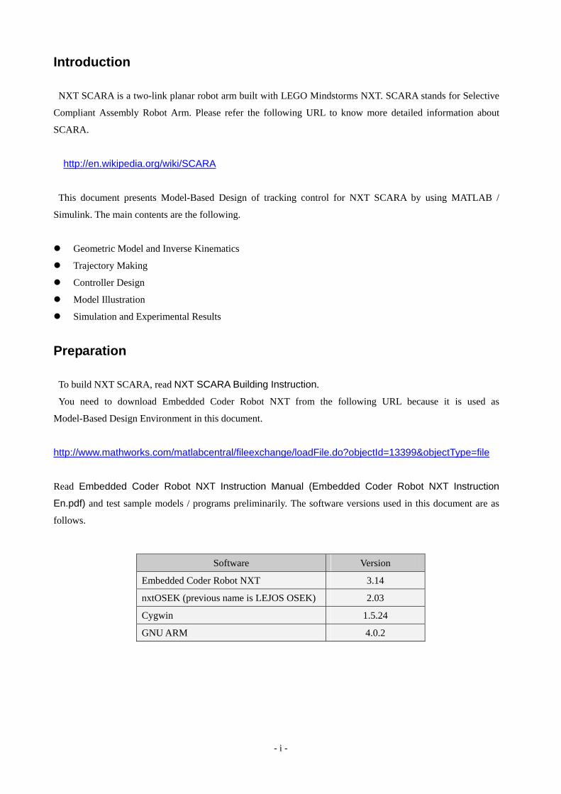
Introduction
NXT SCARA is a two-link planar robot arm built with LEGO Mindstorms NXT. SCARA stands for Selective
Compliant Assembly Robot Arm. Please refer the following URL to know more detailed information about
SCARA.
http://en.wikipedia.org/wiki/SCARA
This document presents Model-Based Design of tracking control for NXT SCARA by using MATLAB /
Simulink. The main contents are the following.
Geometric Model and Inverse Kinematics
Trajectory Making
Controller Design
Model Illustration
Simulation and Experimental Results
Preparation
To build NXT SCARA, read NXT SCARA Building Instruction.
You need to download Embedded Coder Robot NXT from the following URL because it is used as
Model-Based Design Environment in this document.
http://www.mathworks.com/matlabcentral/fileexchange/loadFile.do?objectId=13399&objectType=file
Read Embedded Coder Robot NXT Instruction Manual (Embedded Coder Robot NXT Instruction
En.pdf) and test sample models / programs preliminarily. The software versions used in this document are as
follows.
Software Version
Embedded Coder Robot NXT 3.14
nxtOSEK (previous name is LEJOS OSEK) 2.03
Cygwin 1.5.24
GNU ARM 4.0.2
- i -
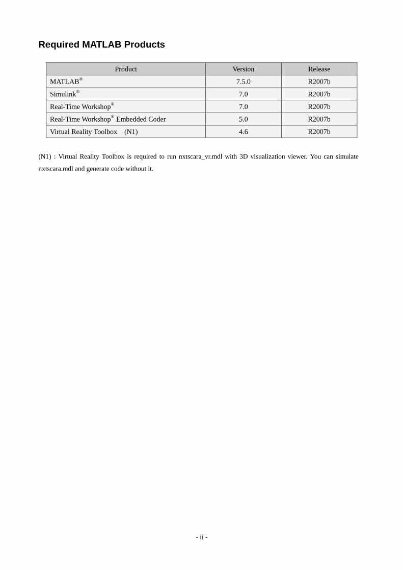
Required MATLAB Products
Product Version Release
MATLAB® 7.5.0 R2007b
Simulink® 7.0 R2007b
Real-Time Workshop® 7.0 R2007b
Real-Time Workshop® Embedded Coder 5.0 R2007b
Virtual Reality Toolbox (N1) 4.6 R2007b
(N1) : Virtual Reality Toolbox is required to run nxtscara_vr.mdl with 3D visualization viewer. You can simulate
nxtscara.mdl and generate code without it.
- ii -
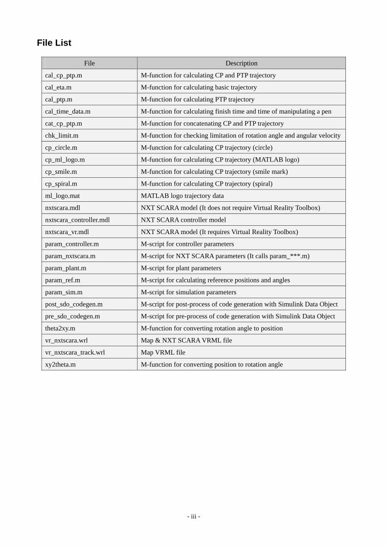
File List
File Description
cal_cp_ptp.m M-function for calculating CP and PTP trajectory
cal_eta.m M-function for calculating basic trajectory
cal_ptp.m M-function for calculating PTP trajectory
cal_time_data.m M-function for calculating finish time and time of manipulating a pen
cat_cp_ptp.m M-function for concatenating CP and PTP trajectory
chk_limit.m M-function for checking limitation of rotation angle and angular velocity
cp_circle.m M-function for calculating CP trajectory (circle)
cp_ml_logo.m M-function for calculating CP trajectory (MATLAB logo)
cp_smile.m M-function for calculating CP trajectory (smile mark)
cp_spiral.m M-function for calculating CP trajectory (spiral)
ml_logo.mat MATLAB logo trajectory data
nxtscara.mdl NXT SCARA model (It does not require Virtual Reality Toolbox)
nxtscara_controller.mdl NXT SCARA controller model
nxtscara_vr.mdl NXT SCARA model (It requires Virtual Reality Toolbox)
param_controller.m M-script for controller parameters
param_nxtscara.m M-script for NXT SCARA parameters (It calls param_***.m)
param_plant.m M-script for plant parameters
param_ref.m M-script for calculating reference positions and angles
param_sim.m M-script for simulation parameters
post_sdo_codegen.m M-script for post-process of code generation with Simulink Data Object
pre_sdo_codegen.m M-script for pre-process of code generation with Simulink Data Object
theta2xy.m M-function for converting rotation angle to position
vr_nxtscara.wrl Map & NXT SCARA VRML file
vr_nxtscara_track.wrl Map VRML file
xy2theta.m M-function for converting position to rotation angle
- iii -
Table of Contents
Introduction ............................................................................................................................................................... i Preparation................................................................................................................................................................ i Required MATLAB Products ................................................................................................................................. ii File List .................................................................................................................................................................... iii 1 Model-Based Design ...................................................................................................................................... 1
1.1 What is Model-Based Design?.............................................................................................................. 1 1.2 V-Process ................................................................................................................................................. 2 1.3 Merits of MBD .......................................................................................................................................... 3
2 NXT SCARA System ...................................................................................................................................... 4 2.1 Structure ................................................................................................................................................... 4 2.2 Sensors and Actuators ........................................................................................................................... 4 2.3 Gear Trains and Backlash ..................................................................................................................... 5 2.4 Link Angle and Link Angular Velocity Limitation ................................................................................. 6
3 NXT SCARA Modeling ................................................................................................................................... 8 3.1 Two-Link Planar Robot Arm................................................................................................................... 8 3.2 Inverse Kinematics.................................................................................................................................. 9
4 Trajectory Making.......................................................................................................................................... 11 4.1 Making Procedure of Trajectory Function ......................................................................................... 11 4.2 Basic Trajectory Calculation using 5-1-5 Polynomial ...................................................................... 11 4.3 CP Motion and PTP Motion ................................................................................................................. 13
5 NXT SCARA Controller Design................................................................................................................... 14 5.1 Control System ...................................................................................................................................... 14 5.2 Controller Design .................................................................................................................................. 15
6 NXT SCARA Model....................................................................................................................................... 16 6.1 Model Summary .................................................................................................................................... 16 6.2 Parameter Files ..................................................................................................................................... 21 6.3 Trajectory Calculation ........................................................................................................................... 22
7 Plant Model .................................................................................................................................................... 23 7.1 Model Summary .................................................................................................................................... 23 7.2 Plant ........................................................................................................................................................ 24 7.3 Engage Detect and Backlash Remove .............................................................................................. 25 7.4 Simulation Stop ..................................................................................................................................... 26
8 Controller Model ............................................................................................................................................ 27 8.1 Control Program Summary .................................................................................................................. 27 8.2 Model Summary .................................................................................................................................... 29 8.3 Initialization Task : task_init ................................................................................................................. 32 8.4 50ms Task : task_ts1 ............................................................................................................................ 32 8.5 100ms Task : task_ts2 .......................................................................................................................... 40
8.6 Tuning Parameters ............................................................................................................................... 41 9 Simulation....................................................................................................................................................... 42
9.1 How to Run Simulation......................................................................................................................... 42 9.2 Simulation Results ................................................................................................................................ 43 9.3 3D Viewer ............................................................................................................................................... 45
10 Code Generation and Implementation ................................................................................................... 46 10.1 Target Hardware and Software ........................................................................................................... 46 10.2 How to Generate Code and Download .............................................................................................. 47 10.3 Experimental Results............................................................................................................................ 48
11 Challenges for Readers ............................................................................................................................... 50 Appendix Generated Code ............................................................................................................................... 51 References............................................................................................................................................................. 57
- 1 -
1 Model-Based Design
This chapter outlines Model-Based Design briefly.
1.1 What is Model-Based Design?
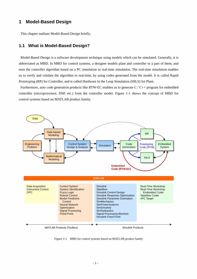
Model-Based Design is a software development technique using models which can be simulated. Generally, it is
abbreviated as MBD. In MBD for control systems, a designer models plant and controller or a part of them, and
tests the controller algorithm based on a PC simulation or real-time simulation. The real-time simulation enables
us to verify and validate the algorithm in real-time, by using codes generated from the model. It is called Rapid
Prototyping (RP) for Controller, and is called Hardware In the Loop Simulation (HILS) for Plant.
Furthermore, auto code generation products like RTW-EC enables us to generate C / C++ program for embedded
controller (microprocessor, DSP, etc.) from the controller model. Figure 1-1 shows the concept of MBD for
control systems based on MATLAB product family.
Simulink Stateflow Simulink Control Design Simulink Response OptimizationSimulink Parameter EstimationSimMechanics SimPowerSystems SimDriveline SimHydraulics Signal Processing Blockset Simulink Fixed Point
Control SystemDesign & Analysis SimulationEngineering
Problem
Mathematical Modeling
Code Generation
RP
HILS
EmbeddedSystem
Data
Data basedModeling
Prototyping Code (RTW)
Embedded Code (RTW-EC)
MATLAB
Data Acquisition Instrument Control OPC
Control System System Identification Fuzzy Logic Robust Control Model Predictive Control Neural Network Optimization Signal Processing Fixed-Point
Real-Time Workshop Real-Time Workshop Embedded Coder Stateflow Coder xPC Target
MATLAB Products (Toolbox) Simulink Products
Figure 1-1 MBD for control systems based on MATLAB product family
- 2 -
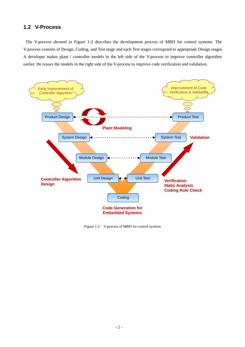
1.2 V-Process
The V-process showed in Figure 1-2 describes the development process of MBD for control systems. The
V-process consists of Design, Coding, and Test stage and each Test stages correspond to appropriate Design stages.
A developer makes plant / controller models in the left side of the V-process to improve controller algorithm
earlier. He reuses the models in the right side of the V-process to improve code verification and validation.
System Design
Module Design
Unit Design
Coding
Unit Test
Module Test
System Test
Product Test
Plant Modeling
Controller Algorithm Design
Code Generation for Embedded Systems
Verification Static Analysis Coding Rule Check
Early Improvement ofController Algorithm
Improvement of Code Verification & Validation
Product Design
Validation
Figure 1-2 V-process of MBD for control systems

- 3 -
1.3 Merits of MBD
MBD has the following merits.
Error detection about specifications in early stage of development
Hardware prototype reduction and fail-safe verification by real-time simulation
Efficient test by model verification
Effective communication by model usage
Coding time and error reduction by auto code generation
- 4 -
2 NXT SCARA System
This chapter describes the structure and the sensors / actuators of NXT SCARA.
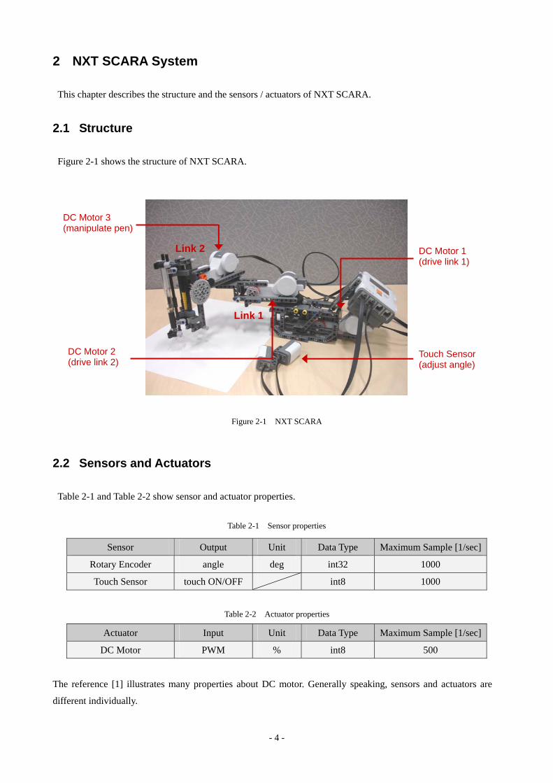
2.1 Structure
Figure 2-1 shows the structure of NXT SCARA.
DC Motor 1 (drive link 1)
Touch Sensor (adjust angle)
DC Motor 2 (drive link 2)
DC Motor 3 (manipulate pen)
Link 2
Link 1
2.2 Sensors and Actuators
Table 2-1 and Table 2-2 show sensor and actuator properties.
The reference [1] illustrates many properties about DC motor. Generally speaking, sensors and actuators are
different individually.
Sensor Output Unit Data Type Maximum Sample [1/sec]
Rotary Encoder angle deg int32 1000
Touch Sensor touch ON/OFF int8 1000
Figure 2-1 NXT SCARA
Table 2-1 Sensor properties
Table 2-2 Actuator properties
Actuator Input Unit Data Type Maximum Sample [1/sec]
DC Motor PWM % int8 500
- 5 -
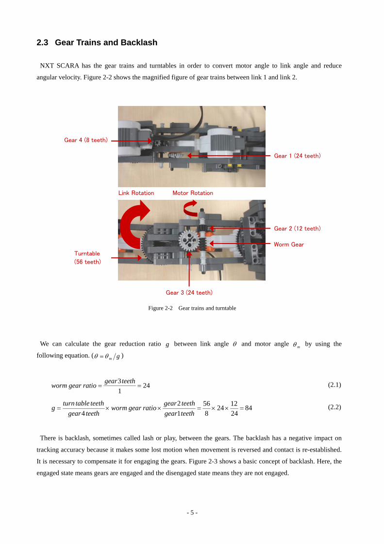
2.3 Gear Trains and Backlash
NXT SCARA has the gear trains and turntables in order to convert motor angle to link angle and reduce
angular velocity. Figure 2-2 shows the magnified figure of gear trains between link 1 and link 2.
Motor Rotation Link Rotation
Turntable
(56 teeth)
Gear 4 (8 teeth)
Gear 1 (24 teeth)
Gear 2 (12 teeth)
Gear 3 (24 teeth)
Worm Gear
Figure 2-2 Gear trains and turntable
We can calculate the gear reduction ratio g between link angle θ and motor angle mθ by using the
following equation. ( gmθθ = )
2413
==teethgear
ratiogearworm (2.1)
84241224
856
12
4=××=××=
teethgearteethgear
ratiogearwormteethgear
teethtableturng (2.2)
There is backlash, sometimes called lash or play, between the gears. The backlash has a negative impact on
tracking accuracy because it makes some lost motion when movement is reversed and contact is re-established.
It is necessary to compensate it for engaging the gears. Figure 2-3 shows a basic concept of backlash. Here, the
engaged state means gears are engaged and the disengaged state means they are not engaged.
- 6 -
Direction of Movement
Engaged State Disengaged State Engaged State
Direction ofMovement
Direction ofMovement
Figure 2-3 Backlash (The upper side is drive gear and under side is driven gear)
The whole backlash of gear trains is larger than each backlash between gears.
2.4 Link Angle and Link Angular Velocity Limitation
There are some limitations on link angle and link angular velocity due to the structure of NXT SCARA.
Maximum Link Angle
The maximum link 1 angle is about 90 [deg] and the maximum link 2 angle is about 140 [deg]. Therefore, the
movable area of the edge of the robot arm is restricted.
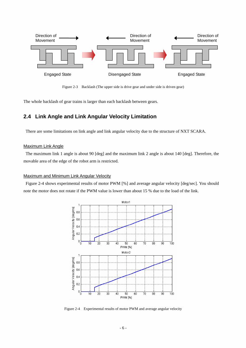
Maximum and Minimum Link Angular Velocity
Figure 2-4 shows experimental results of motor PWM [%] and average angular velocity [deg/sec]. You should
note the motor does not rotate if the PWM value is lower than about 15 % due to the load of the link.
Figure 2-4 Experimental results of motor PWM and average angular velocity
- 7 -
We get the following equation by fitting the linear part showed in Figure 2-4.
)2,1( =+×= ioffsetgainpwm iiii ω (2.3)
, ⎩⎨⎧
==
4.403107.5056
1
1
offsetgain
⎩⎨⎧
==
2.3918106.748
2
2
offsetgain
where and ipwm iω are motor PWM value [%] and average angular velocity [deg/ms] respectively. We can
derive the maximum or minimum motor angular velocity by assigning 100 or 15 to in Eq.(2.3).
Furthermore, we can calculate the maximum and minimum link angular velocity by dividing these values by the gear reduction ratio
pwm
g in Eq.(2.2).
- 8 -
3 NXT SCARA Modeling
This chapter describes a geometric model of NXT SCARA and inverse kinematics that determines each link
angles in order to achieve a desired pose / position. Please refer the reference [2] for more details.
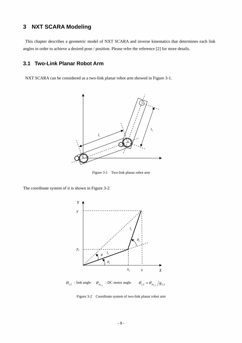
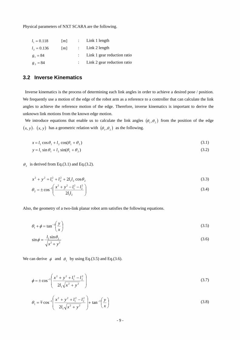
3.1 Two-Link Planar Robot Arm
NXT SCARA can be considered as a two-link planar robot arm showed in Figure 3-1.
The coordinate system of it is shown in Figure 3-2.
2,1θ : link angle : DC motor angle
2,1mθ 2,12,1 2,1gmθθ =
1l2l
Figure 3-1 Two-link planar robot arm
Figure 3-2 Coordinate system of two-link planar robot arm
Y
1l
y
2l
1θ
2θ
1yφ
1x x X
- 9 -
Physical parameters of NXT SCARA are the following.
: Link 1 length 118.01 =l ][m
: Link 2 length 136.02 =l ][m
: Link 1 gear reduction ratio 841 =g
: Link 2 gear reduction ratio 842 =g
3.2 Inverse Kinematics
Inverse kinematics is the process of determining each link angles in order to achieve a desired pose / position.
We frequently use a motion of the edge of the robot arm as a reference to a controller that can calculate the link
angles to achieve the reference motion of the edge. Therefore, inverse kinematics is important to derive the
unknown link motions from the known edge motion. We introduce equations that enable us to calculate the link angles ( )21 ,θθ from the position of the edge
. has a geometric relation with ( )yx, ( yx, ) ( )21 ,θθ as the following.
)cos(cos 21211 θθθ ++= llx (3.1)
)sin(sin 21211 θθθ ++= lly (3.2)
2θ is derived from Eq.(3.1) and Eq.(3.2).
(3.3) 22122
21
22 cos2 θllllyx ++=+
⎟⎟⎠
⎞⎜⎜⎝
⎛ −−+±= −
21
22
21
221
2 2cos
llllyxθ (3.4)
Also, the geometry of a two-link planar robot arm satisfies the following equations.
⎟⎠⎞
⎜⎝⎛=+ −
xy1
1 tanφθ (3.5)
22
22 sinsinyx
l+
=θφ (3.6)
We can derive φ and 1θ by using Eq.(3.5) and Eq.(3.6).
⎟⎟
⎠
⎞
⎜⎜
⎝
⎛
+
−++±= −
221
22
21
221
2cos
yxl
llyxφ (3.7)
⎟⎠⎞
⎜⎝⎛+⎟
⎟
⎠
⎞
⎜⎜
⎝
⎛
+
−++= −−
xy
yxl
llyx 1
221
22
21
221
1 tan2
cosmθ (3.8)
- 10 -
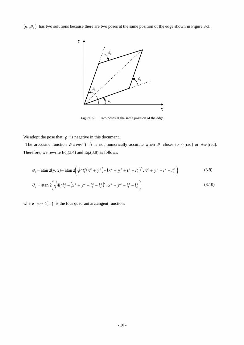
( )21 ,θθ has two solutions because there are two poses at the same position of the edge shown in Figure 3-3.
Y
We adopt the pose that φ is negative in this document.
The arccosine function is not numerically accurate when ( )L1cos −=θ θ closes to [rad] or 0 π± [rad].
Therefore, we rewrite Eq.(3.4) and Eq.(3.8) as follows.
( ) ( ) ( ) ⎟⎠⎞
⎜⎝⎛ −++−++−+−= 2
22
12222
22
122222
11 ,42atan,2atan llyxllyxyxlxyθ (3.9)
( ) ⎟⎠⎞
⎜⎝⎛ −−+−−+−= 2
22
12222
22
1222
22
12 ,42atan llyxllyxllθ (3.10)
where is the four quadrant arctangent function. ( )L2atan
1θ
2θ
2θ
1θ
X
Figure 3-3 Two poses at the same position of the edge
- 11 -
4 Trajectory Making
This chapter describes how to make reference trajectory of the edge of the robot arm.
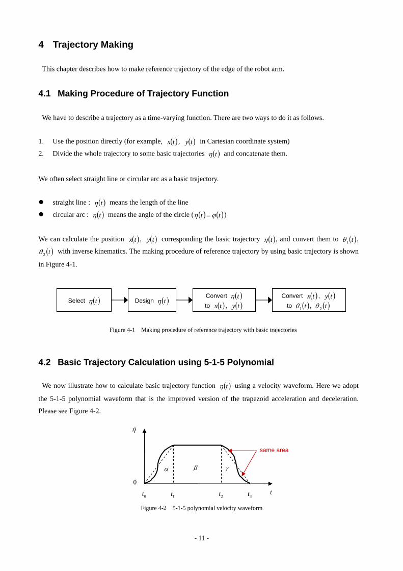
4.1 Making Procedure of Trajectory Function
We have to describe a trajectory as a time-varying function. There are two ways to do it as follows.
1. Use the position directly (for example, ( )tx , ( )ty in Cartesian coordinate system)
2. Divide the whole trajectory to some basic trajectories ( )tη and concatenate them.
We often select straight line or circular arc as a basic trajectory.
straight line : ( )tη means the length of the line
circular arc : ( )tη means the angle of the circle ( ( ) ( )tt ϕη = )
We can calculate the position , corresponding the basic trajectory ( )tx ( )ty ( )tη , and convert them to ( )t1θ ,
( )t2θ with inverse kinematics. The making procedure of reference trajectory by using basic trajectory is shown
in Figure 4-1.
Select ( )tη Design ( )tηConvert ( )tη to ( )tx , ( )ty
Convert ( )tx , ( )ty to ( )t1θ , ( )t2θ
Figure 4-1 Making procedure of reference trajectory with basic trajectories
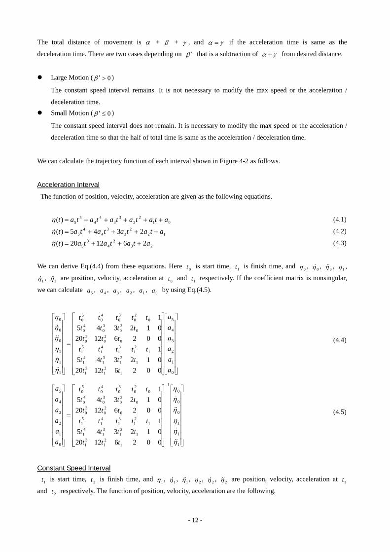
4.2 Basic Trajectory Calculation using 5-1-5 Polynomial We now illustrate how to calculate basic trajectory function ( )tη using a velocity waveform. Here we adopt
the 5-1-5 polynomial waveform that is the improved version of the trapezoid acceleration and deceleration.
Please see Figure 4-2.
η&
same area
β γα 0
t0t 1t 2t 3t
Figure 4-2 5-1-5 polynomial velocity waveform
- 12 -
The total distance of movement is α + β + γ , and γα = if the acceleration time is same as the
deceleration time. There are two cases depending on β ′ that is a subtraction of γα + from desired distance.
Large Motion ( 0>′β )
The constant speed interval remains. It is not necessary to modify the max speed or the acceleration /
deceleration time. Small Motion ( 0≤′β )
The constant speed interval does not remain. It is necessary to modify the max speed or the acceleration /
deceleration time so that the half of total time is same as the acceleration / deceleration time.
We can calculate the trajectory function of each interval shown in Figure 4-2 as follows.
Acceleration Interval
The function of position, velocity, acceleration are given as the following equations.
(4.1) 01
22
33
44
55)( atatatatatat +++++=η
(4.2) 122
33
44
5 2345)( atatatatat ++++=η&
(4.3) 232
43
5 261220)( atatatat +++=η&&
We can derive Eq.(4.4) from these equations. Here is start time, is finish time, and 0t 1t 0η , 0η& , 0η&& , 1η ,
1η& , 1η&& are position, velocity, acceleration at and respectively. If the coefficient matrix is nonsingular,
we can calculate , , , , , by using Eq.(4.5). 0t 1t
5a 4a 3a 2a 1a 0a
(4.4)
⎥⎥⎥⎥⎥⎥⎥⎥
⎦
⎤
⎢⎢⎢⎢⎢⎢⎢⎢
⎣
⎡
⎥⎥⎥⎥⎥⎥⎥⎥
⎦
⎤
⎢⎢⎢⎢⎢⎢⎢⎢
⎣
⎡
=
⎥⎥⎥⎥⎥⎥⎥⎥
⎦
⎤
⎢⎢⎢⎢⎢⎢⎢⎢
⎣
⎡
0
1
2
3
4
5
121
31
121
31
41
121
31
41
51
020
30
020
30
40
020
30
40
50
1
1
1
0
0
0
002612200123451002612200123451
aaaaaa
ttttttt
tttttttt
ttttttttt
ηηηηηη
&&
&
&&
&
(4.5)
⎥⎥⎥⎥⎥⎥⎥⎥
⎦
⎤
⎢⎢⎢⎢⎢⎢⎢⎢
⎣
⎡
⎥⎥⎥⎥⎥⎥⎥⎥
⎦
⎤
⎢⎢⎢⎢⎢⎢⎢⎢
⎣
⎡
=
⎥⎥⎥⎥⎥⎥⎥⎥
⎦
⎤
⎢⎢⎢⎢⎢⎢⎢⎢
⎣
⎡−
1
1
1
0
0
01
121
31
121
31
41
121
31
41
51
020
30
020
30
40
020
30
40
50
0
1
2
3
4
5
002612200123451002612200123451
ηηηηηη
&&
&
&&
&
ttttttt
tttttttt
ttttttttt
aaaaaa
Constant Speed Interval is start time, is finish time, and 1t 2t 1η , 1η& , 1η&& , 2η , 2η& , 2η&& are position, velocity, acceleration at
and respectively. The function of position, velocity, acceleration are the following. 1t
2t
- 13 -
(4.6) ( ) 111)( ηηη +−= ttt &
(4.7) 21)( ηηη &&& ==t
(4.8) 0)( 21 === ηηη &&&&&& t
Deceleration Interval
We can calculate it by the same way as the acceleration interval.
The basic trajectory function of NXT SCARA is calculated in cal_eta.m.
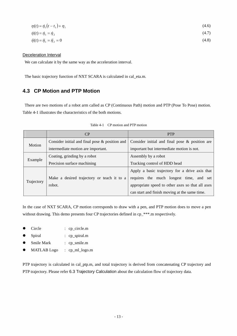
4.3 CP Motion and PTP Motion
There are two motions of a robot arm called as CP (Continuous Path) motion and PTP (Pose To Pose) motion.
Table 4-1 illustrates the characteristics of the both motions.
Table 4-1 CP motion and PTP motion
CP PTP
Motion Consider initial and final pose & position and
intermediate motion are important.
Consider initial and final pose & position are
important but intermediate motion is not.
Example Coating, grinding by a robot
Precision surface machining
Assembly by a robot
Tracking control of HDD head
Trajectory Make a desired trajectory or teach it to a
robot.
Apply a basic trajectory for a drive axis that
requires the much longest time, and set
appropriate speed to other axes so that all axes
can start and finish moving at the same time.
In the case of NXT SCARA, CP motion corresponds to draw with a pen, and PTP motion does to move a pen
without drawing. This demo presents four CP trajectories defined in cp_***.m respectively.
Circle : cp_circle.m
Spiral : cp_spiral.m
Smile Mark : cp_smile.m
MATLAB Logo : cp_ml_logo.m
PTP trajectory is calculated in cal_ptp.m, and total trajectory is derived from concatenating CP trajectory and
PTP trajectory. Please refer 6.3 Trajectory Calculation about the calculation flow of trajectory data.
- 14 -
5 NXT SCARA Controller Design
This chapter describes NXT SCARA controller design for tracking reference trajectory.
5.1 Control System
The characteristics of NXT SCARA as control system are as follows.
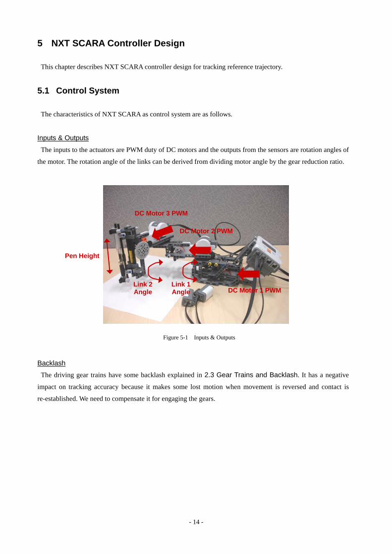
Inputs & Outputs
The inputs to the actuators are PWM duty of DC motors and the outputs from the sensors are rotation angles of
the motor. The rotation angle of the links can be derived from dividing motor angle by the gear reduction ratio.
DC Motor 1 PWM
DC Motor 2 PWM
DC Motor 3 PWM
Pen Height
Link 1 Angle
Link 2 Angle
Figure 5-1 Inputs & Outputs
Backlash
The driving gear trains have some backlash explained in 2.3 Gear Trains and Backlash. It has a negative
impact on tracking accuracy because it makes some lost motion when movement is reversed and contact is
re-established. We need to compensate it for engaging the gears.
- 15 -
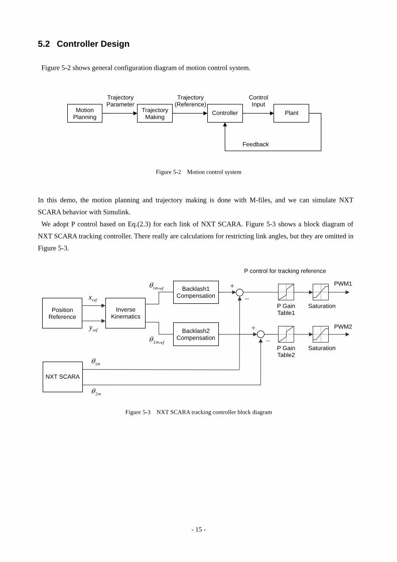
5.2 Controller Design
Figure 5-2 shows general configuration diagram of motion control system.
Motion Planning
Trajectory Making
Controller Plant
Trajectory Parameter
Trajectory (Reference)
Control Input
Feedback
Figure 5-2 Motion control system
In this demo, the motion planning and trajectory making is done with M-files, and we can simulate NXT
SCARA behavior with Simulink.
We adopt P control based on Eq.(2.3) for each link of NXT SCARA. Figure 5-3 shows a block diagram of
NXT SCARA tracking controller. There really are calculations for restricting link angles, but they are omitted in
Figure 5-3.
P control for tracking reference
P Gain Table1
+
−Saturation
refx
refy
Backlash1 Compensation
Backlash2 Compensation
Inverse Kinematics
P Gain Table2
+
−Saturation
NXT SCARA
m1θ
m2θ
refm1θ
refm2θ
PWM2
Position Reference
PWM1
Figure 5-3 NXT SCARA tracking controller block diagram
- 16 -
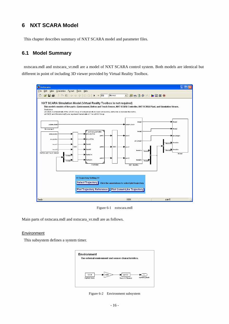
6 NXT SCARA Model
This chapter describes summary of NXT SCARA model and parameter files.
6.1 Model Summary
nxtscara.mdl and nxtscara_vr.mdl are a model of NXT SCARA control system. Both models are identical but
different in point of including 3D viewer provided by Virtual Reality Toolbox.
Main parts of nxtscara.mdl and nxtscara_vr.mdl are as follows.
Environment
This subsystem defines a system timer.
Figure 6-1 nxtscara.mdl
Figure 6-2 Environment subsystem
- 17 -
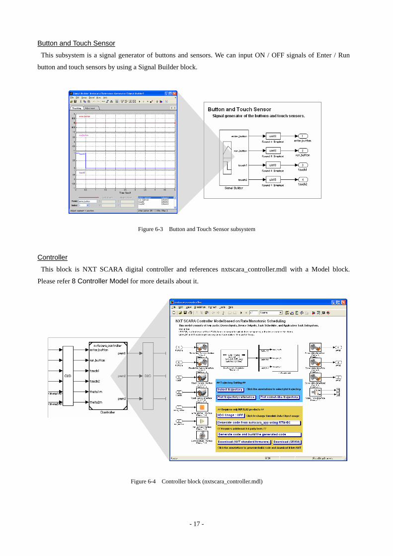
Button and Touch Sensor
This subsystem is a signal generator of buttons and sensors. We can input ON / OFF signals of Enter / Run
button and touch sensors by using a Signal Builder block.
Figure 6-3 Button and Touch Sensor subsystem
Controller
This block is NXT SCARA digital controller and references nxtscara_controller.mdl with a Model block.
Please refer 8 Controller Model for more details about it.
Figure 6-4 Controller block (nxtscara_controller.mdl)
- 18 -
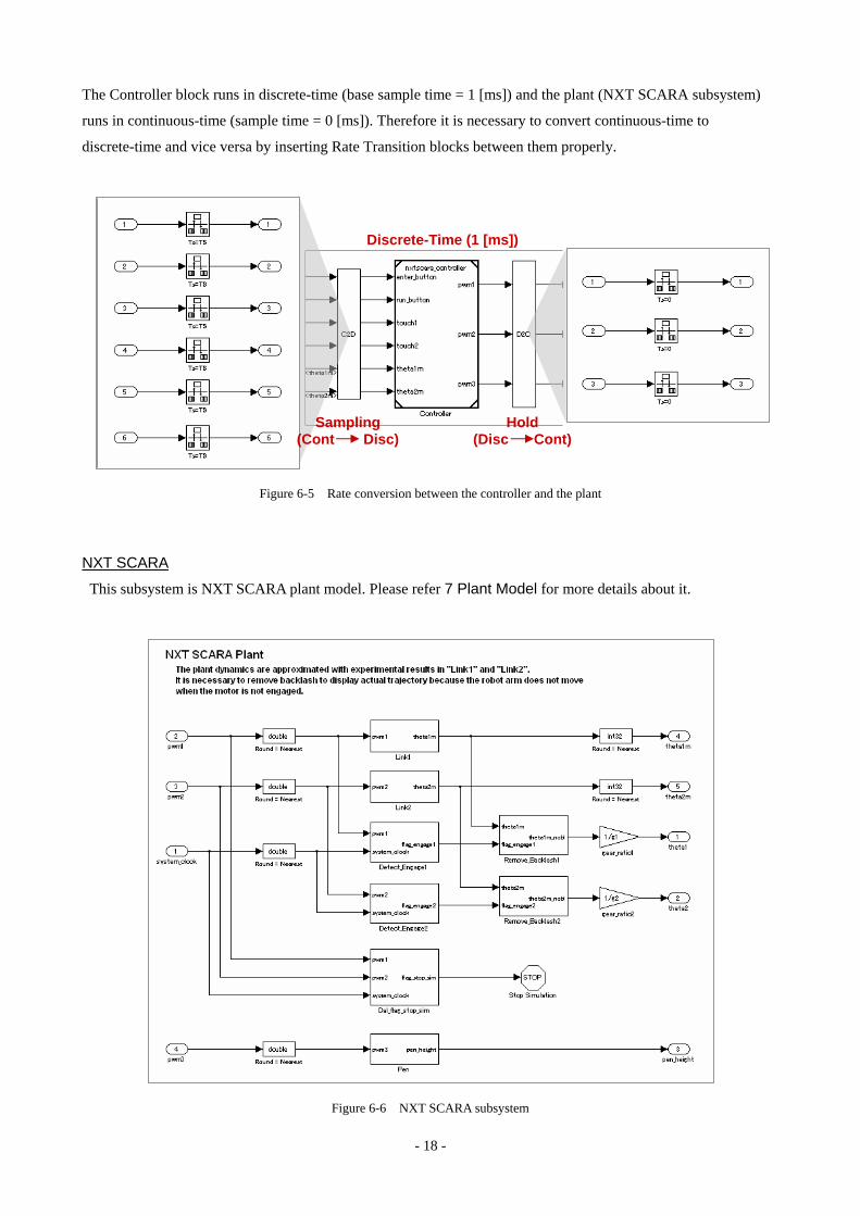
The Controller block runs in discrete-time (base sample time = 1 [ms]) and the plant (NXT SCARA subsystem)
runs in continuous-time (sample time = 0 [ms]). Therefore it is necessary to convert continuous-time to
discrete-time and vice versa by inserting Rate Transition blocks between them properly.
Discrete-Time (1 [ms])
Sampling (Cont Disc)
Hold (Disc Cont)
NXT SCARA
This subsystem is NXT SCARA plant model. Please refer 7 Plant Model for more details about it.
Figure 6-5 Rate conversion between the controller and the plant
Figure 6-6 NXT SCARA subsystem
- 19 -
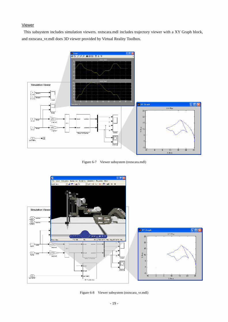
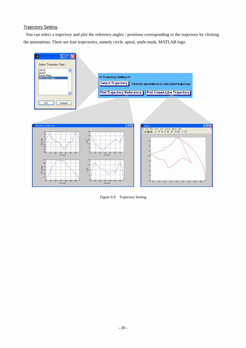
Viewer
This subsystem includes simulation viewers. nxtscara.mdl includes trajectory viewer with a XY Graph block,
and nxtscara_vr.mdl does 3D viewer provided by Virtual Reality Toolbox.
Figure 6-7 Viewer subsystem (nxtscara.mdl)
Figure 6-8 Viewer subsystem (nxtscara_vr.mdl)
- 20 -
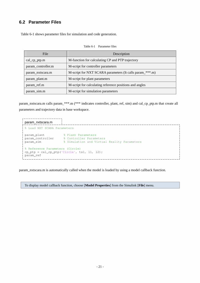
Trajectory Setting
You can select a trajectory and plot the reference angles / positions corresponding to the trajectory by clicking
the annotations. There are four trajectories, namely circle, spiral, smile mark, MATLAB logo.
Figure 6-9 Trajectory Setting
- 21 -
6.2 Parameter Files
Table 6-1 shows parameter files for simulation and code generation.
Table 6-1 Parameter files
File Description
cal_cp_ptp.m M-function for calculating CP and PTP trajectory
param_controller.m M-script for controller parameters
param_nxtscara.m M-script for NXT SCARA parameters (It calls param_***.m)
param_plant.m M-script for plant parameters
param_ref.m M-script for calculating reference positions and angles
param_sim.m M-script for simulation parameters
param_nxtscara.m calls param_***.m (*** indicates controller, plant, ref, sim) and cal_cp_ptp.m that create all
parameters and trajectory data in base workspace.
param_nxtscara.m % Load NXT SCARA Parameters param_plant % Plant Parameters param_controller % Controller Parameters param_sim % Simulation and Virtual Reality Parameters % Reference Parameters (Circle) cp_ptp = cal_cp_ptp('Circle', ts1, l1, l2); param_ref
param_nxtscara.m is automatically called when the model is loaded by using a model callback function.
To display model callback function, choose [Model Properties] from the Simulink [File] menu.
- 22 -
6.3 Trajectory Calculation
Table 6-2 shows trajectory calculation files.
Table 6-2 Trajectory calculation files
File Description
cal_cp_ptp.m M-function for calculating CP and PTP trajectory
cal_eta.m M-function for calculating basic trajectory
cal_ptp.m M-function for calculating PTP trajectory
cal_time_data.m M-function for calculating finish time and time of manipulating a pen
cat_cp_ptp.m M-function for concatenating CP and PTP trajectory
chk_limit.m M-function for checking limit of rotation angle and angular velocity
cp_circle.m M-function for calculating CP trajectory (circle)
cp_ml_logo.m M-function for calculating CP trajectory (MATLAB logo)
cp_smile.m M-function for calculating CP trajectory (smile mark)
cp_spiral.m M-function for calculating CP trajectory (spiral)
ml_logo.mat MATLAB logo data
theta2xy.m M-function for converting rotation angle to position
xy2theta.m M-function for converting position to rotation angle
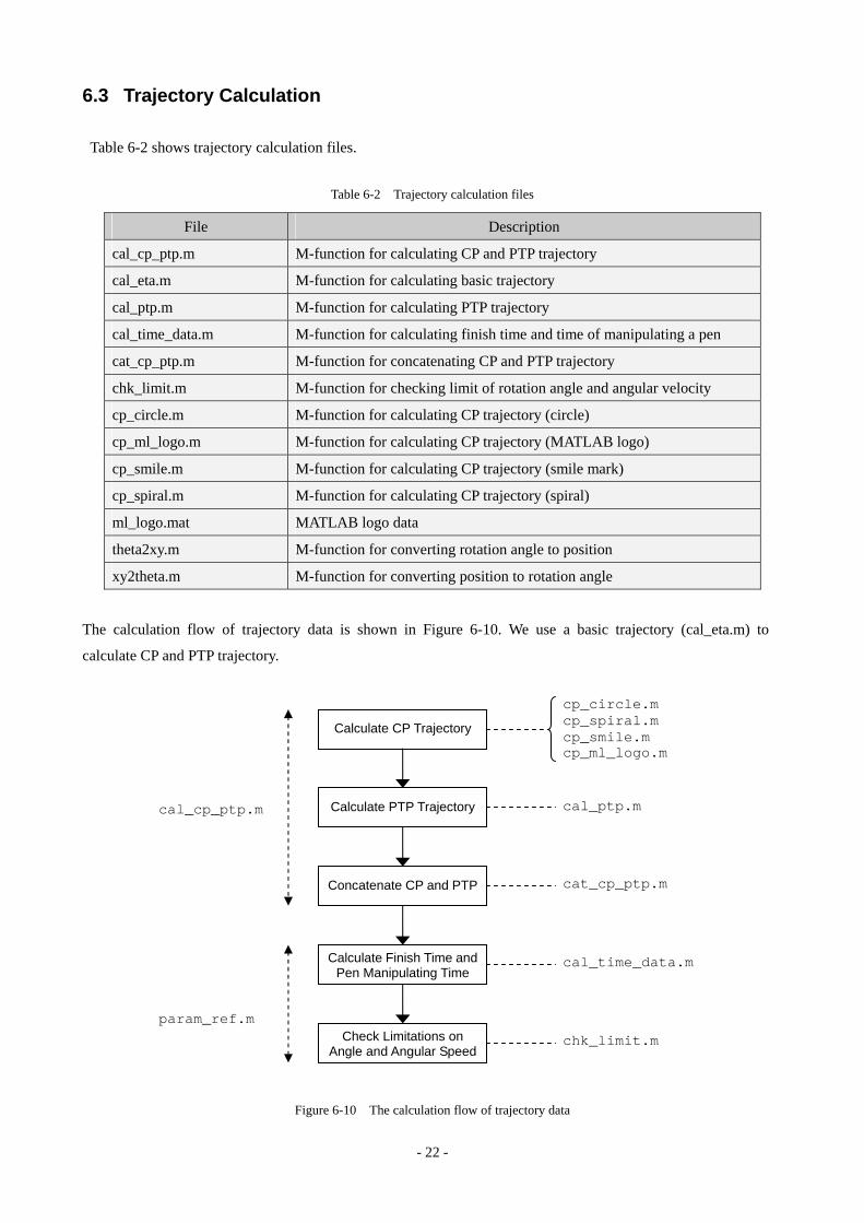
The calculation flow of trajectory data is shown in Figure 6-10. We use a basic trajectory (cal_eta.m) to
calculate CP and PTP trajectory.
cp_circle.m cp_spiral.m cp_smile.m cp_ml_logo.m
Check Limitations on Angle and Angular Speed
Calculate CP Trajectory
Calculate PTP Trajectory
Concatenate CP and PTP
Calculate Finish Time and Pen Manipulating Time
cal_cp_ptp.m cal_ptp.m
cat_cp_ptp.m
cal_time_data.m
chk_limit.m
param_ref.m
Figure 6-10 The calculation flow of trajectory data
- 23 -
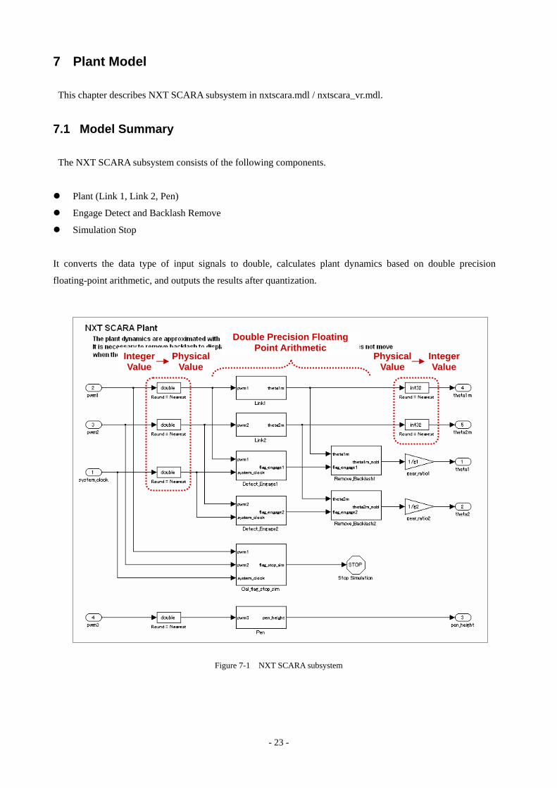
7 Plant Model
This chapter describes NXT SCARA subsystem in nxtscara.mdl / nxtscara_vr.mdl.
7.1 Model Summary
The NXT SCARA subsystem consists of the following components.
Plant (Link 1, Link 2, Pen)
Engage Detect and Backlash Remove
Simulation Stop
It converts the data type of input signals to double, calculates plant dynamics based on double precision
floating-point arithmetic, and outputs the results after quantization.
Integer Value
Physical Value
Double Precision FloatingPoint Arithmetic
Integer Value
Physical Value
Figure 7-1 NXT SCARA subsystem
- 24 -
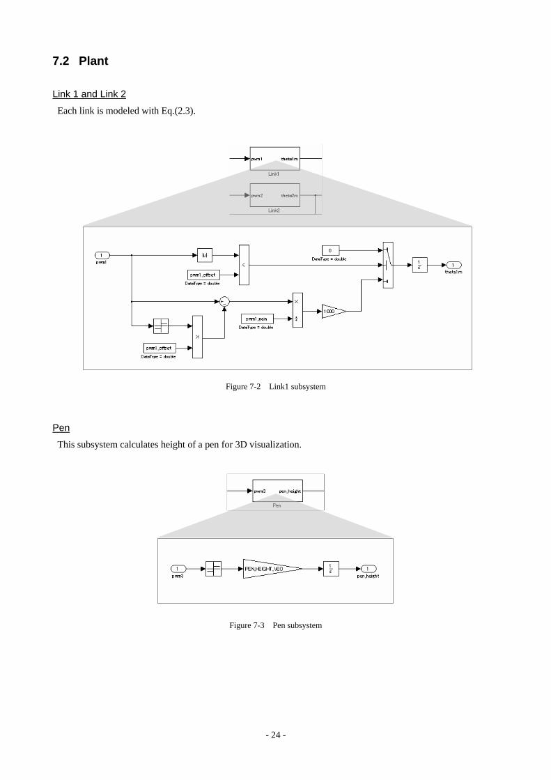
7.2 Plant
Link 1 and Link 2
Each link is modeled with Eq.(2.3).
Figure 7-2 Link1 subsystem
Pen
This subsystem calculates height of a pen for 3D visualization.
Figure 7-3 Pen subsystem
- 25 -
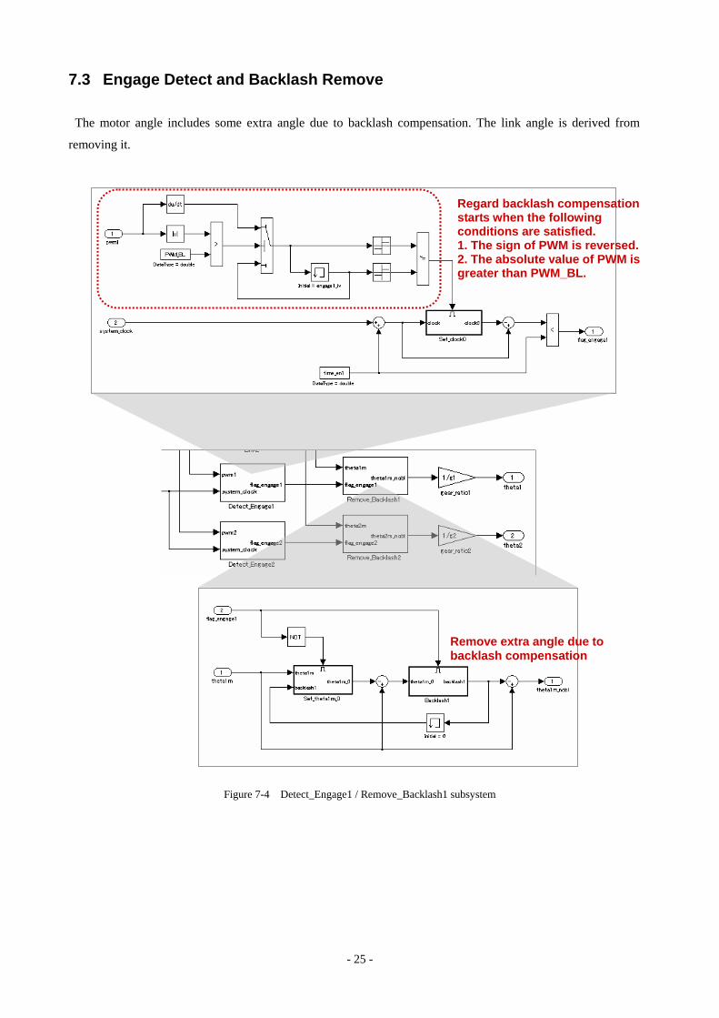
7.3 Engage Detect and Backlash Remove
The motor angle includes some extra angle due to backlash compensation. The link angle is derived from
removing it.
Remove extra angle due to backlash compensation
Regard backlash compensation starts when the following conditions are satisfied. 1. The sign of PWM is reversed.2. The absolute value of PWM is greater than PWM_BL.
Figure 7-4 Detect_Engage1 / Remove_Backlash1 subsystem
- 26 -
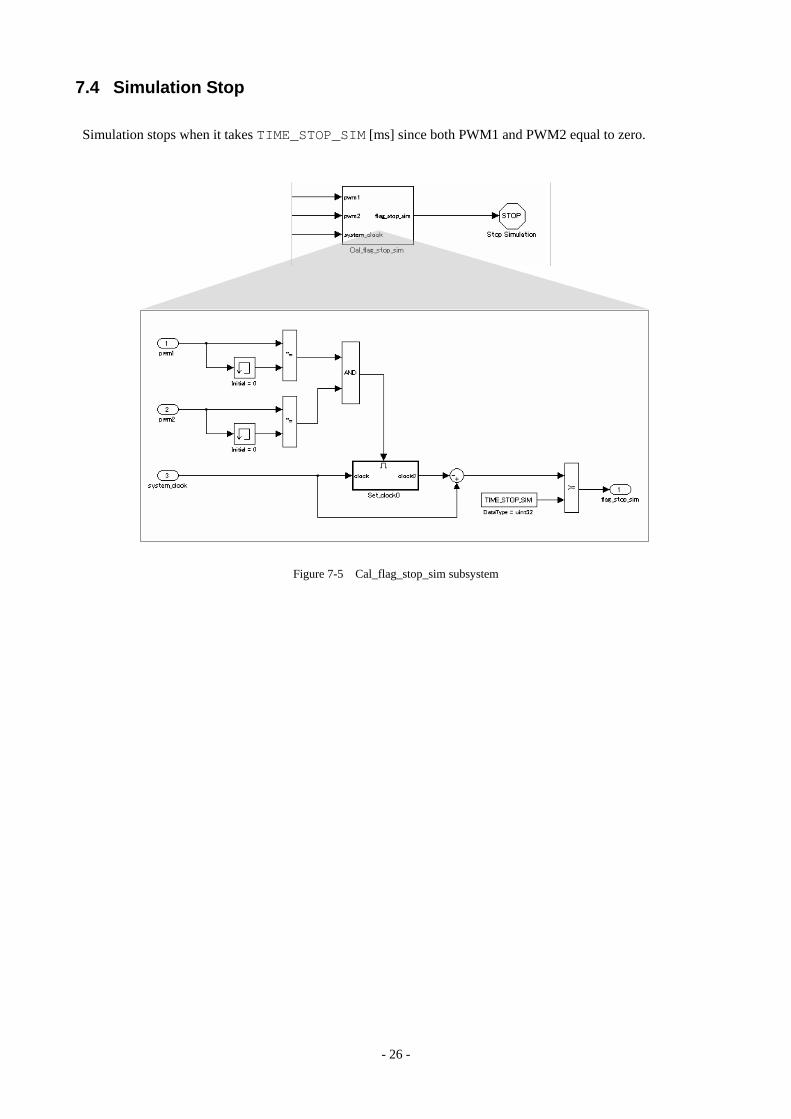
7.4 Simulation Stop
Simulation stops when it takes TIME_STOP_SIM [ms] since both PWM1 and PWM2 equal to zero.
Figure 7-5 Cal_flag_stop_sim subsystem
- 27 -
8 Controller Model
This chapter describes control program, task configuration, and model contents of nxtscara_controller.mdl.
8.1 Control Program Summary
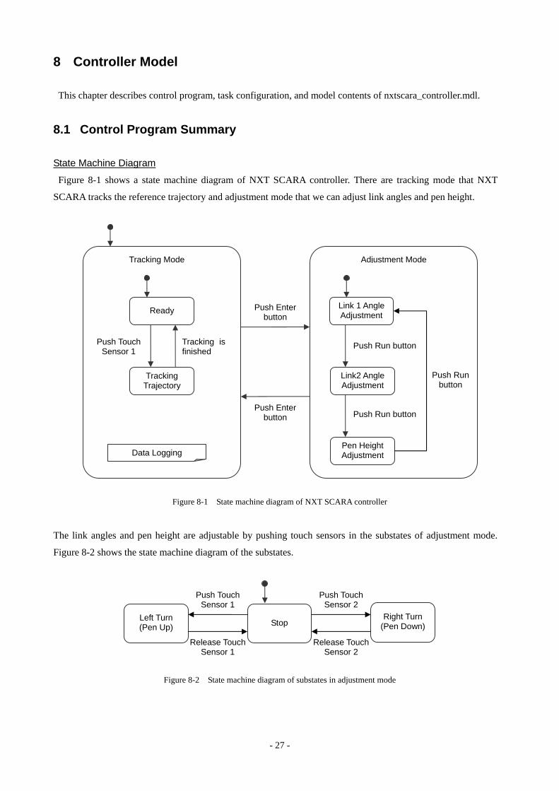
State Machine Diagram
Figure 8-1 shows a state machine diagram of NXT SCARA controller. There are tracking mode that NXT
SCARA tracks the reference trajectory and adjustment mode that we can adjust link angles and pen height.
Data Logging
Tracking Mode
Ready
Tracking Trajectory
Tracking is finished
Push Touch Sensor 1
Adjustment Mode
Link 1 AngleAdjustment
Push Run button
Link2 AngleAdjustment
Pen HeightAdjustment
Push Run button
Push Run button
Push Enter button
Push Enter button
Figure 8-1 State machine diagram of NXT SCARA controller
The link angles and pen height are adjustable by pushing touch sensors in the substates of adjustment mode.
Figure 8-2 shows the state machine diagram of the substates.
Stop Right Turn
(Pen Down)
Push Touch Sensor 2
Left Turn (Pen Up)
Push Touch Sensor 1
Release TouchSensor 1
Release TouchSensor 2
Figure 8-2 State machine diagram of substates in adjustment mode
- 28 -
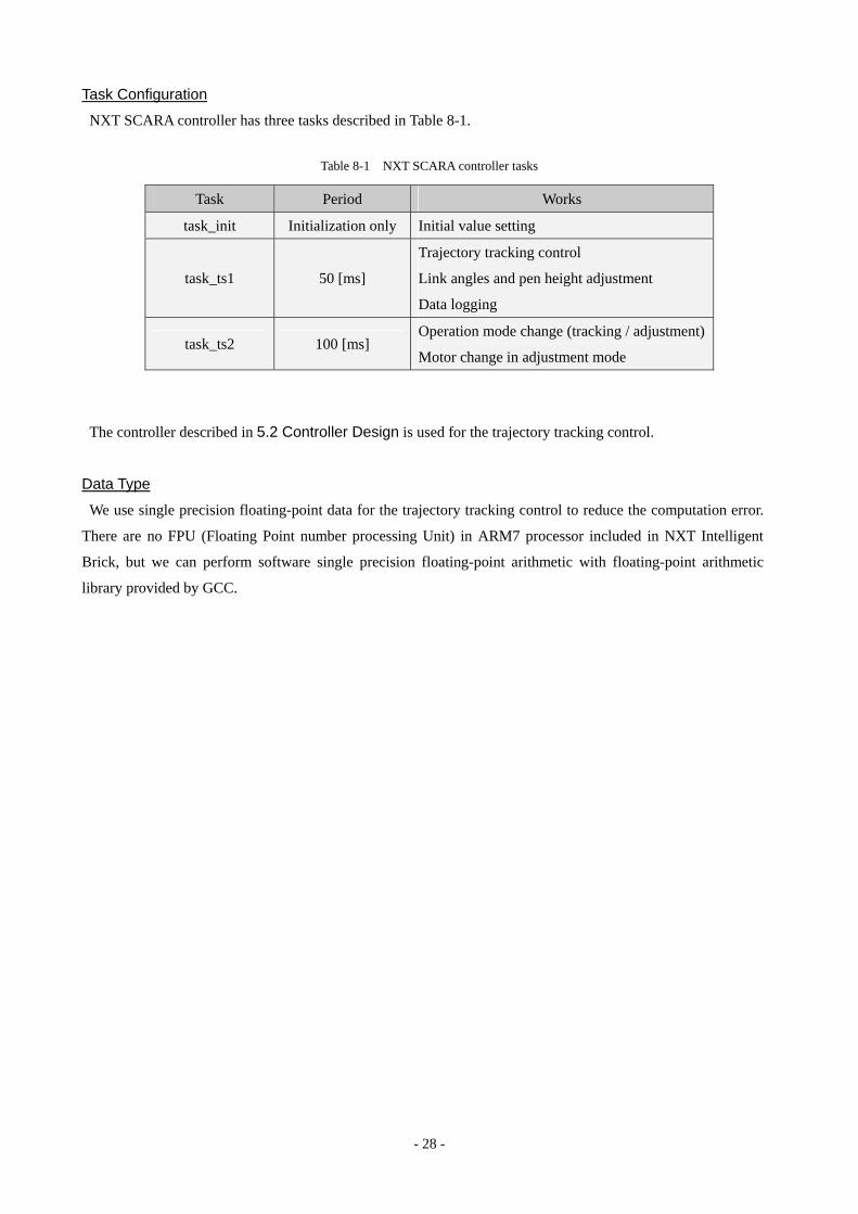
Task Configuration
NXT SCARA controller has three tasks described in Table 8-1.
Table 8-1 NXT SCARA controller tasks
Task Period Works
task_init Initialization only Initial value setting
task_ts1 50 [ms]
Trajectory tracking control
Link angles and pen height adjustment
Data logging
task_ts2 100 [ms]
Operation mode change (tracking / adjustment) Motor change in adjustment mode
The controller described in 5.2 Controller Design is used for the trajectory tracking control.
Data Type
We use single precision floating-point data for the trajectory tracking control to reduce the computation error.
There are no FPU (Floating Point number processing Unit) in ARM7 processor included in NXT Intelligent
Brick, but we can perform software single precision floating-point arithmetic with floating-point arithmetic
library provided by GCC.
- 29 -
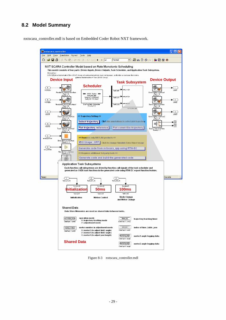
8.2 Model Summary
nxtscara_controller.mdl is based on Embedded Coder Robot NXT framework.
50ms 100ms
Device Input Device Output Scheduler
Task Subsystem
Initialization
Shared Data
Figure 8-3 nxtscara_controller.mdl
- 30 -
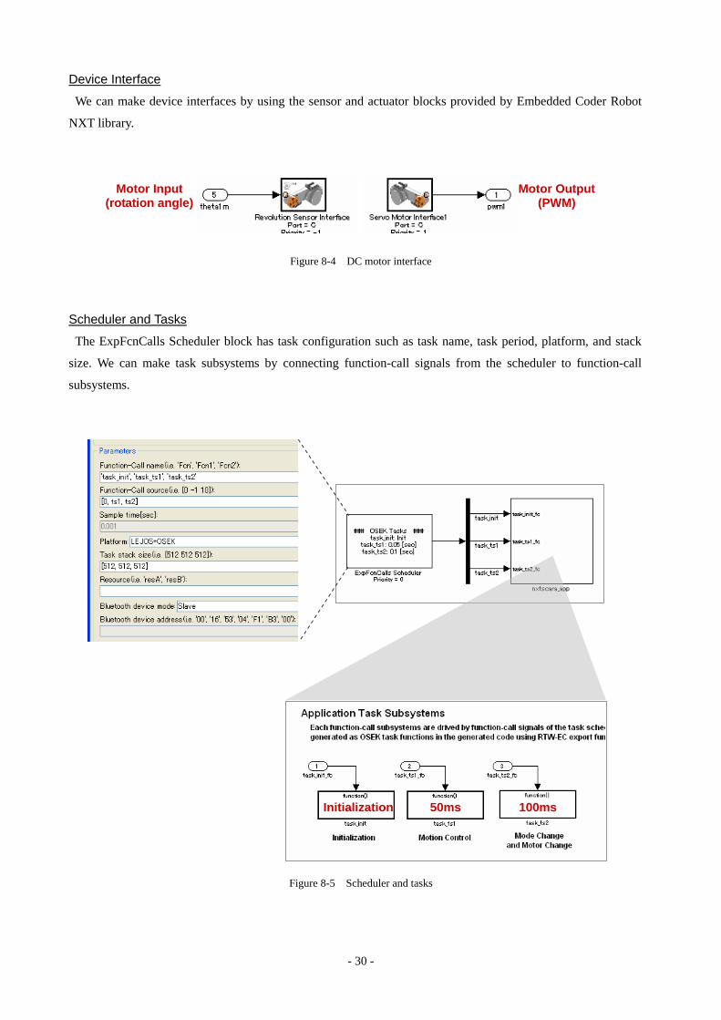
Device Interface
We can make device interfaces by using the sensor and actuator blocks provided by Embedded Coder Robot
NXT library.
Motor Input (rotation angle)
Motor Output (PWM)
Figure 8-4 DC motor interface
Scheduler and Tasks
The ExpFcnCalls Scheduler block has task configuration such as task name, task period, platform, and stack
size. We can make task subsystems by connecting function-call signals from the scheduler to function-call
subsystems.
50ms 100ms Initialization
Figure 8-5 Scheduler and tasks
- 31 -
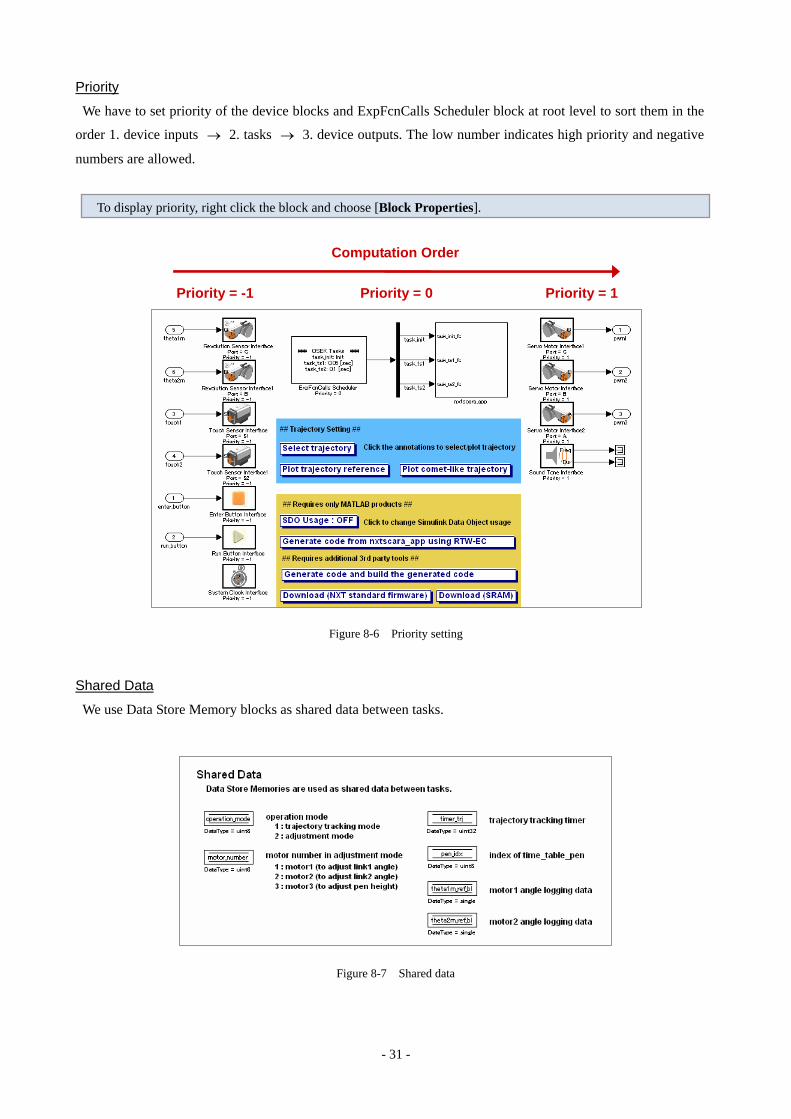
Priority
We have to set priority of the device blocks and ExpFcnCalls Scheduler block at root level to sort them in the
order 1. device inputs 2. tasks → 3. device outputs. The low number indicates high priority and negative
numbers are allowed.
→
To display priority, right click the block and choose [Block Properties].
Computation Order
Priority = -1 Priority = 0 Priority = 1
Shared Data
We use Data Store Memory blocks as shared data between tasks.
Figure 8-6 Priority setting
Figure 8-7 Shared data
- 32 -
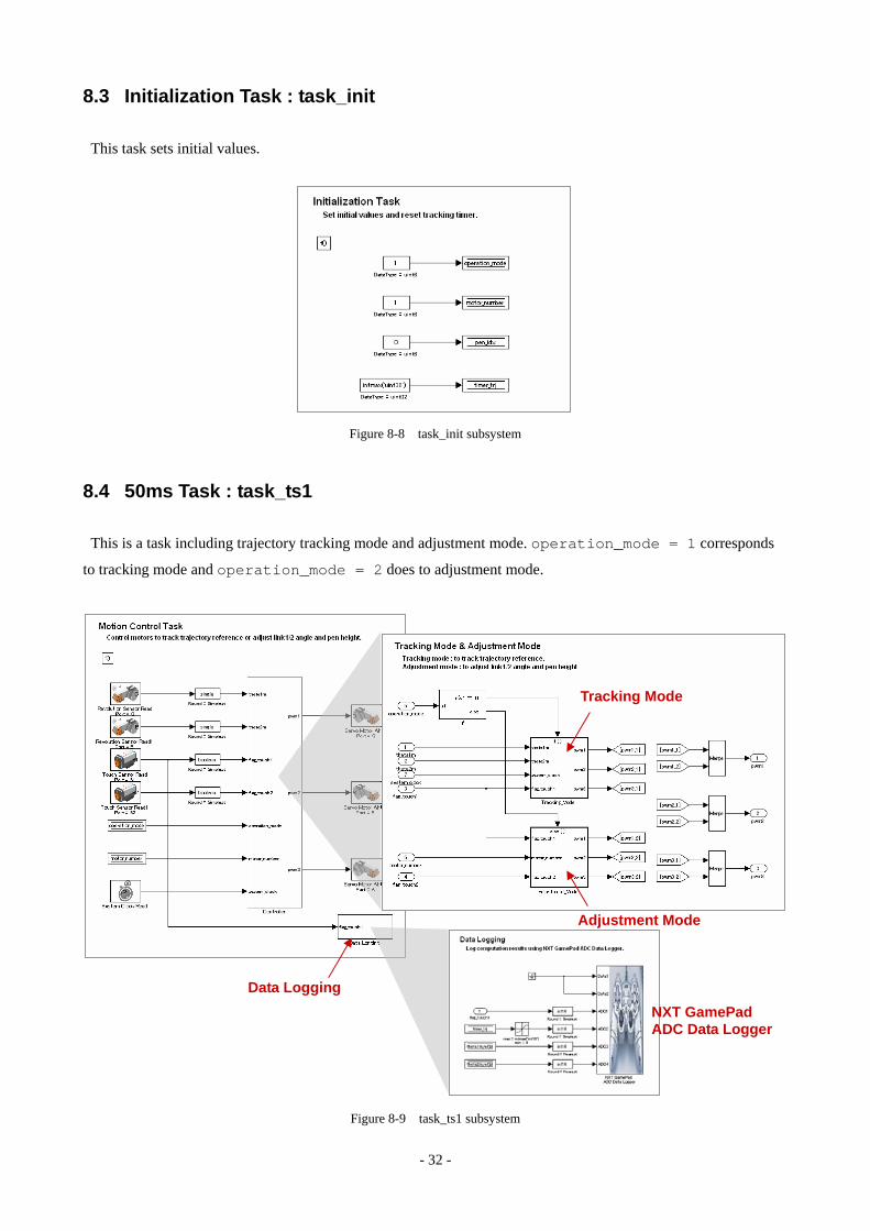
8.3 Initialization Task : task_init
This task sets initial values.
Figure 8-8 task_init subsystem
8.4 50ms Task : task_ts1
This is a task including trajectory tracking mode and adjustment mode. operation_mode = 1 corresponds
to tracking mode and operation_mode = 2 does to adjustment mode.
Tracking Mode
Adjustment Mode
Data Logging NXT GamePad ADC Data Logger
Figure 8-9 task_ts1 subsystem
- 33 -
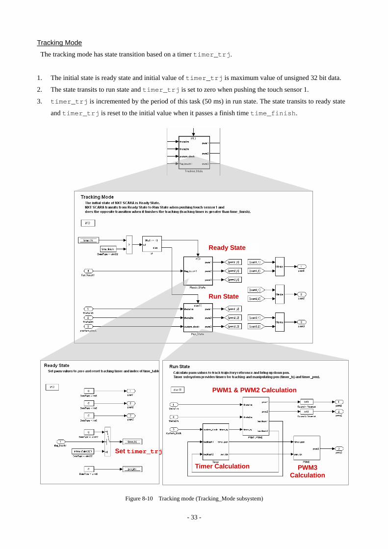
Tracking Mode
The tracking mode has state transition based on a timer timer_trj.
1. The initial state is ready state and initial value of timer_trj is maximum value of unsigned 32 bit data.
2. The state transits to run state and timer_trj is set to zero when pushing the touch sensor 1.
3. timer_trj is incremented by the period of this task (50 ms) in run state. The state transits to ready state
and timer_trj is reset to the initial value when it passes a finish time time_finish.
Ready State
Set timer_trj
PWM 計算
Run State
Timer Calculation
PWM1 & PWM2 Calculation
PWM3 Calculation
Figure 8-10 Tracking mode (Tracking_Mode subsystem)
- 34 -
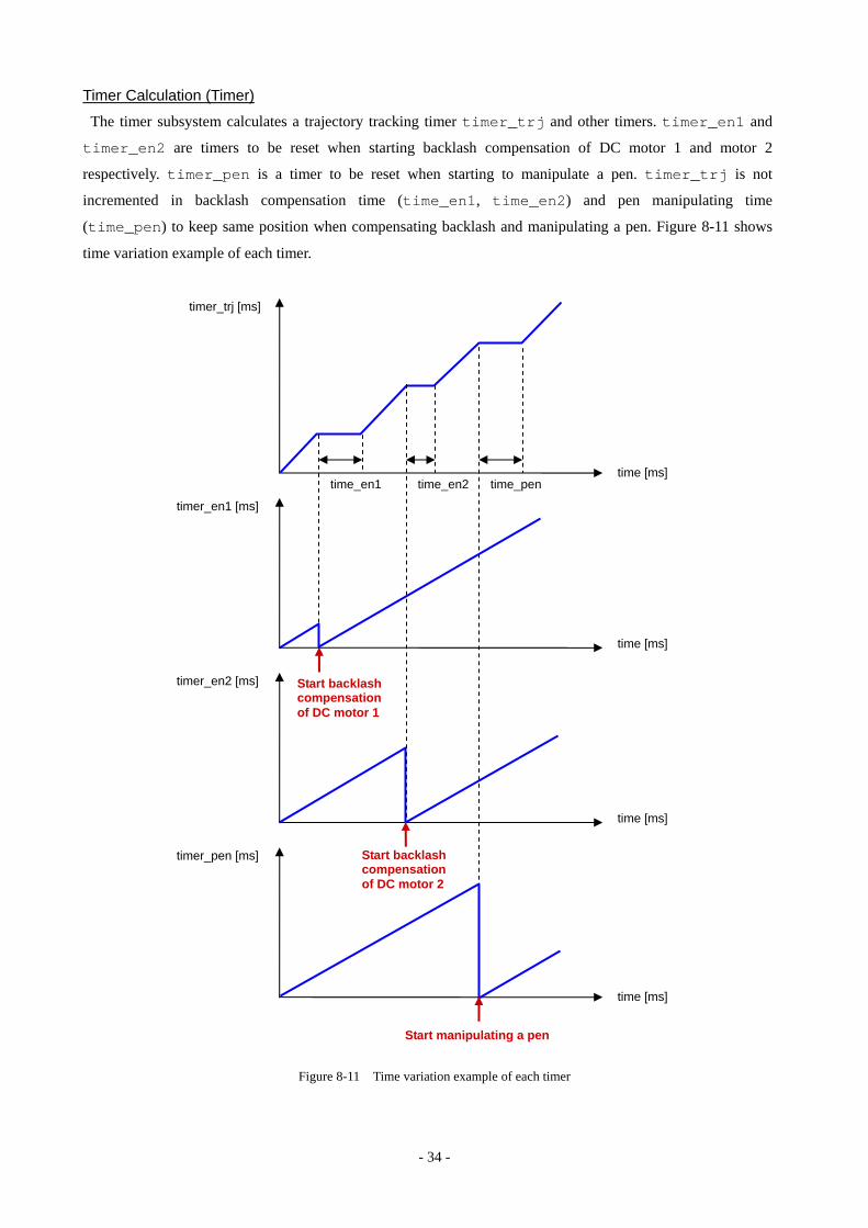
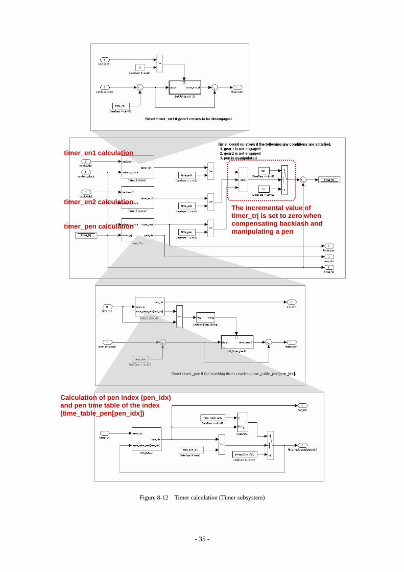
Timer Calculation (Timer)
The timer subsystem calculates a trajectory tracking timer timer_trj and other timers. timer_en1 and
timer_en2 are timers to be reset when starting backlash compensation of DC motor 1 and motor 2
respectively. timer_pen is a timer to be reset when starting to manipulate a pen. timer_trj is not
incremented in backlash compensation time (time_en1, time_en2) and pen manipulating time
(time_pen) to keep same position when compensating backlash and manipulating a pen. Figure 8-11 shows
time variation example of each timer.
time_en1 time_en2 time_pentime [ms]
timer_trj [ms]
Start backlash compensation of DC motor 1
time [ms]
time [ms]
timer_en1 [ms]
timer_en2 [ms]
timer_pen [ms]
Start backlash compensation of DC motor 2
Start manipulating a pen
time [ms]
Figure 8-11 Time variation example of each timer
- 35 -
timer_en1 calculation
timer_en2 calculation
timer_pen calculation
The incremental value of timer_trj is set to zero when compensating backlash and manipulating a pen
Calculation of pen index (pen_idx) and pen time table of the index (time_table_pen[pen_idx])
Figure 8-12 Timer calculation (Timer subsystem)
- 36 -
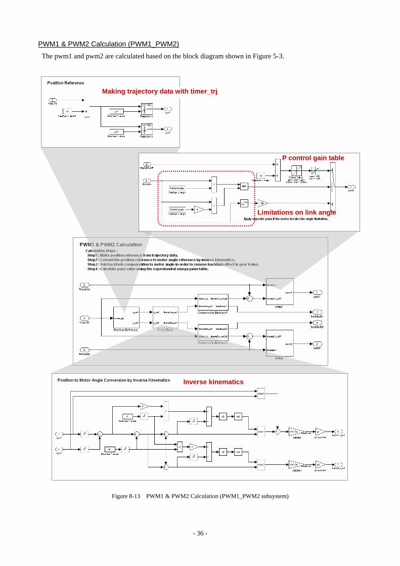
PWM1 & PWM2 Calculation (PWM1_PWM2)
The pwm1 and pwm2 are calculated based on the block diagram shown in Figure 5-3.
Inverse kinematics
Making trajectory data with timer_trj
P control gain table
Limitations on link angle
Figure 8-13 PWM1 & PWM2 Calculation (PWM1_PWM2 subsystem)
- 37 -
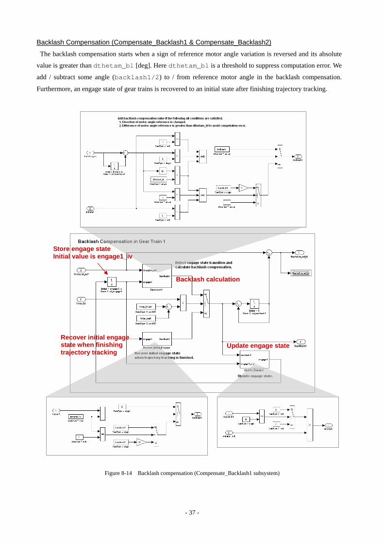
Backlash Compensation (Compensate_Backlash1 & Compensate_Backlash2)
The backlash compensation starts when a sign of reference motor angle variation is reversed and its absolute
value is greater than dthetam_bl [deg]. Here dthetam_bl is a threshold to suppress computation error. We
add / subtract some angle (backlash1/2) to / from reference motor angle in the backlash compensation.
Furthermore, an engage state of gear trains is recovered to an initial state after finishing trajectory tracking.
Backlash calculation
Recover initial engage state when finishing trajectory tracking
Update engage state
Store engage state Initial value is engage1_iv
Figure 8-14 Backlash compensation (Compensate_Backlash1 subsystem)
- 38 -
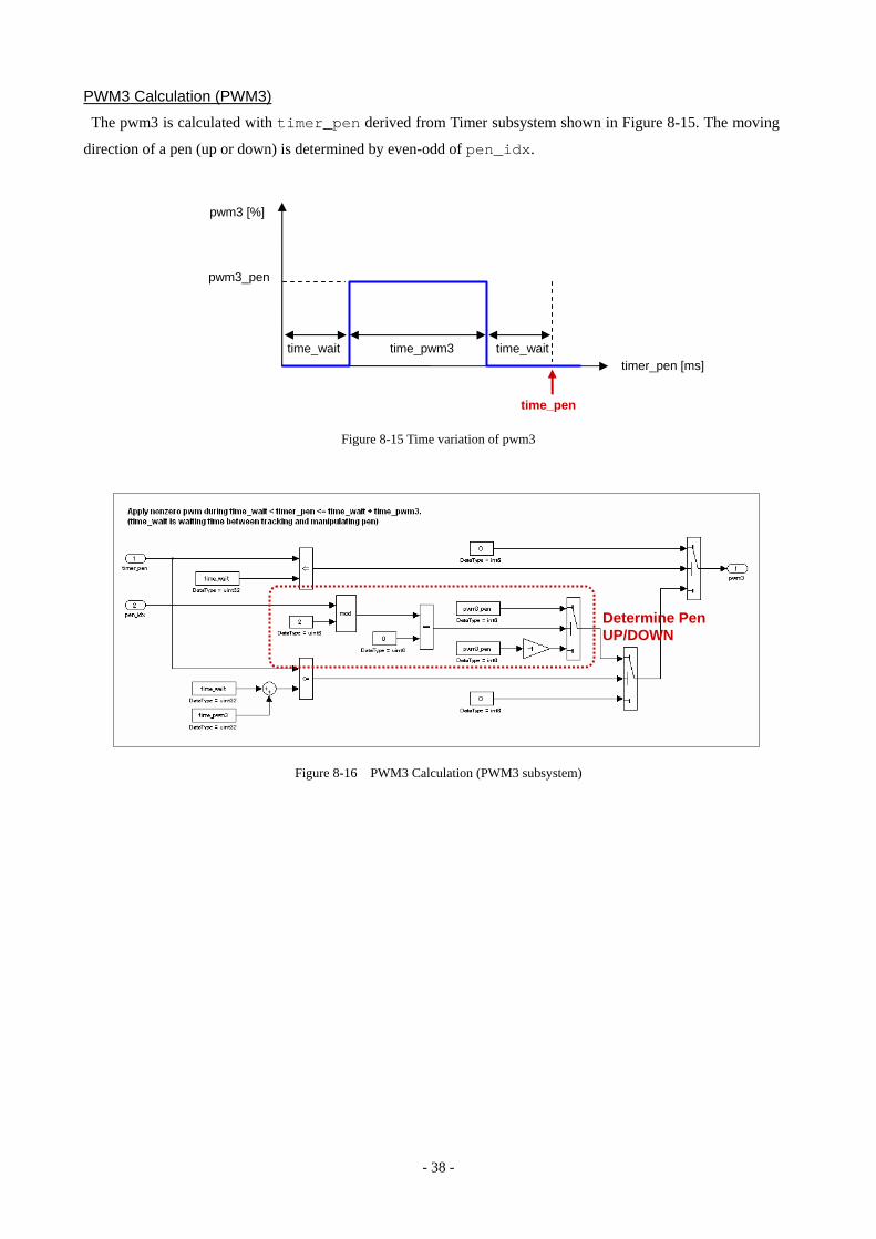
PWM3 Calculation (PWM3)
The pwm3 is calculated with timer_pen derived from Timer subsystem shown in Figure 8-15. The moving
direction of a pen (up or down) is determined by even-odd of pen_idx.
time_wait time_pwm3timer_pen [ms]
pwm3 [%]
time_wait
pwm3_pen
time_pen
Figure 8-15 Time variation of pwm3
Determine Pen UP/DOWN
Figure 8-16 PWM3 Calculation (PWM3 subsystem)
- 39 -
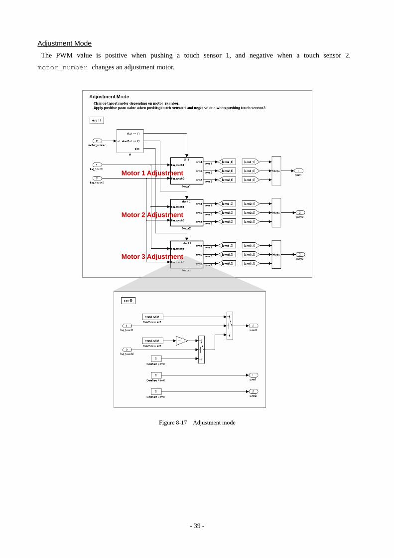
Adjustment Mode
The PWM value is positive when pushing a touch sensor 1, and negative when a touch sensor 2.
motor_number changes an adjustment motor.
Motor 1 Adjustment
Motor 2 Adjustment
Motor 3 Adjustment
Figure 8-17 Adjustment mode
- 40 -
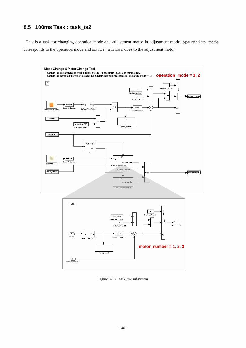
8.5 100ms Task : task_ts2
This is a task for changing operation mode and adjustment motor in adjustment mode. operation_mode
corresponds to the operation mode and motor_number does to the adjustment motor.
operation_mode = 1, 2
motor_number = 1, 2, 3
Figure 8-18 task_ts2 subsystem
- 41 -
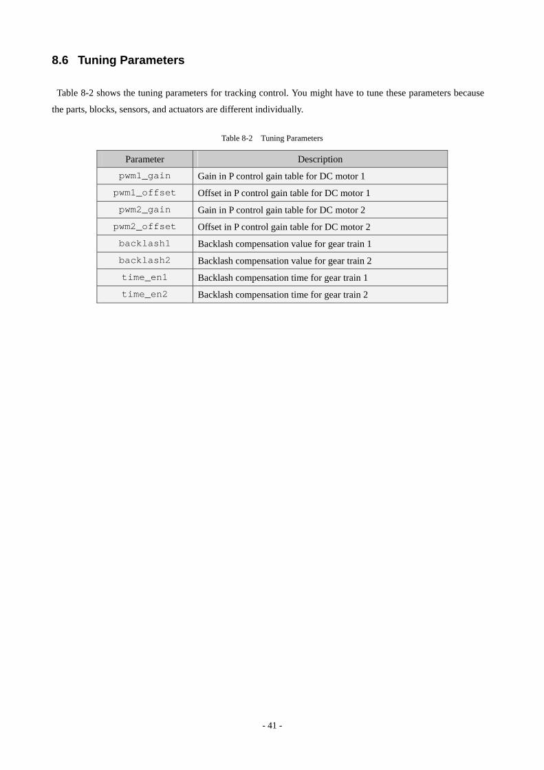
8.6 Tuning Parameters
Table 8-2 shows the tuning parameters for tracking control. You might have to tune these parameters because
the parts, blocks, sensors, and actuators are different individually.
Table 8-2 Tuning Parameters
Parameter Description
pwm1_gain Gain in P control gain table for DC motor 1
pwm1_offset Offset in P control gain table for DC motor 1
pwm2_gain Gain in P control gain table for DC motor 2
pwm2_offset Offset in P control gain table for DC motor 2
backlash1 Backlash compensation value for gear train 1
backlash2 Backlash compensation value for gear train 2
time_en1 Backlash compensation time for gear train 1
time_en2 Backlash compensation time for gear train 2
- 42 -
9 Simulation
This chapter describes simulation of NXT SCARA model, its result, and 3D viewer in nxtscara_vr.mdl.
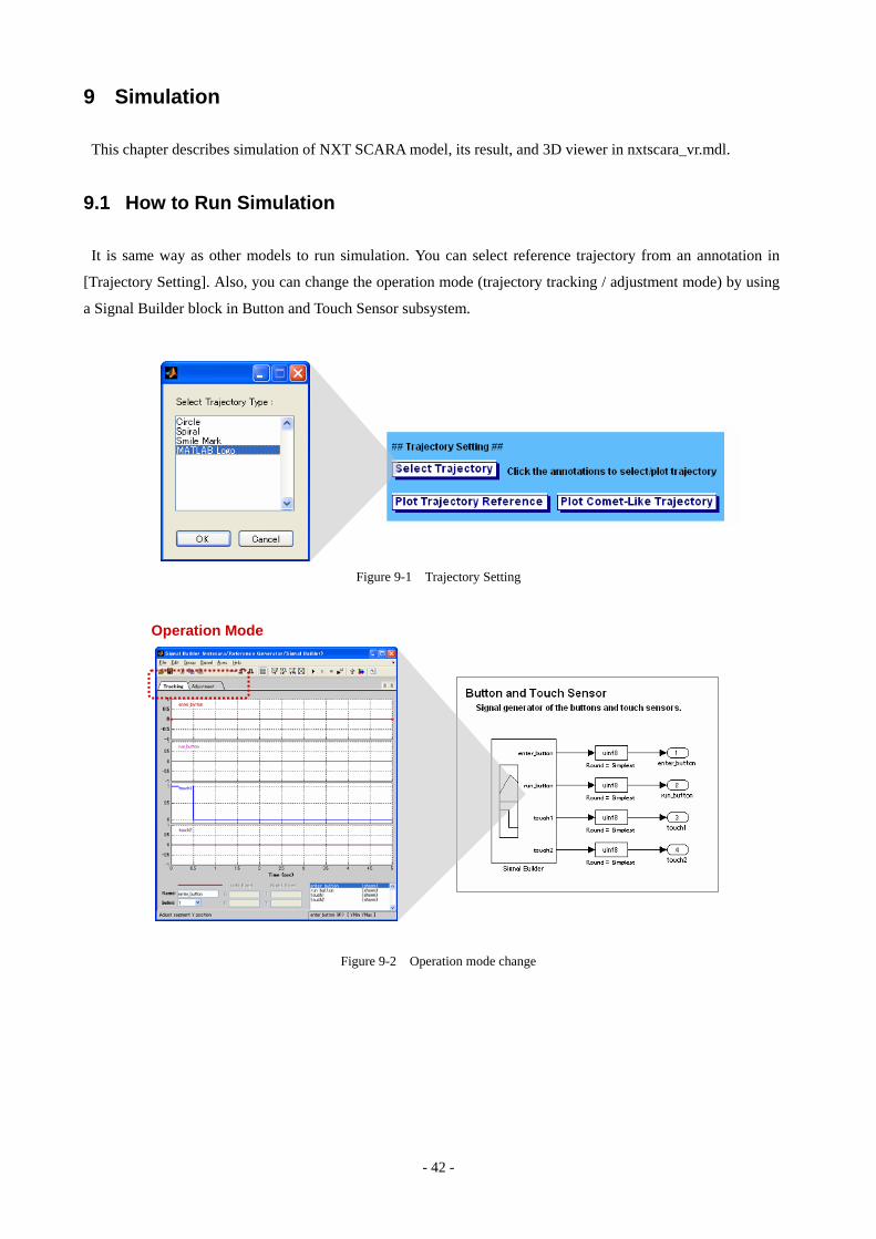
9.1 How to Run Simulation
It is same way as other models to run simulation. You can select reference trajectory from an annotation in
[Trajectory Setting]. Also, you can change the operation mode (trajectory tracking / adjustment mode) by using
a Signal Builder block in Button and Touch Sensor subsystem.
Figure 9-1 Trajectory Setting
Operation Mode
Figure 9-2 Operation mode change
- 43 -
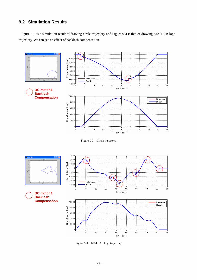
9.2 Simulation Results
Figure 9-3 is a simulation result of drawing circle trajectory and Figure 9-4 is that of drawing MATLAB logo
trajectory. We can see an effect of backlash compensation.
DC motor 1 Backlash Compensation
Figure 9-3 Circle trajectory
DC motor 1 Backlash Compensation
Figure 9-4 MATLAB logo trajectory
- 44 -
You can watch a movie of NXT SCARA simulation drawing MATLAB logo at the following URL.
http://www.youtube.com/watch?v=kanmZErt4io
Figure 9-5 Simulation movie
- 45 -
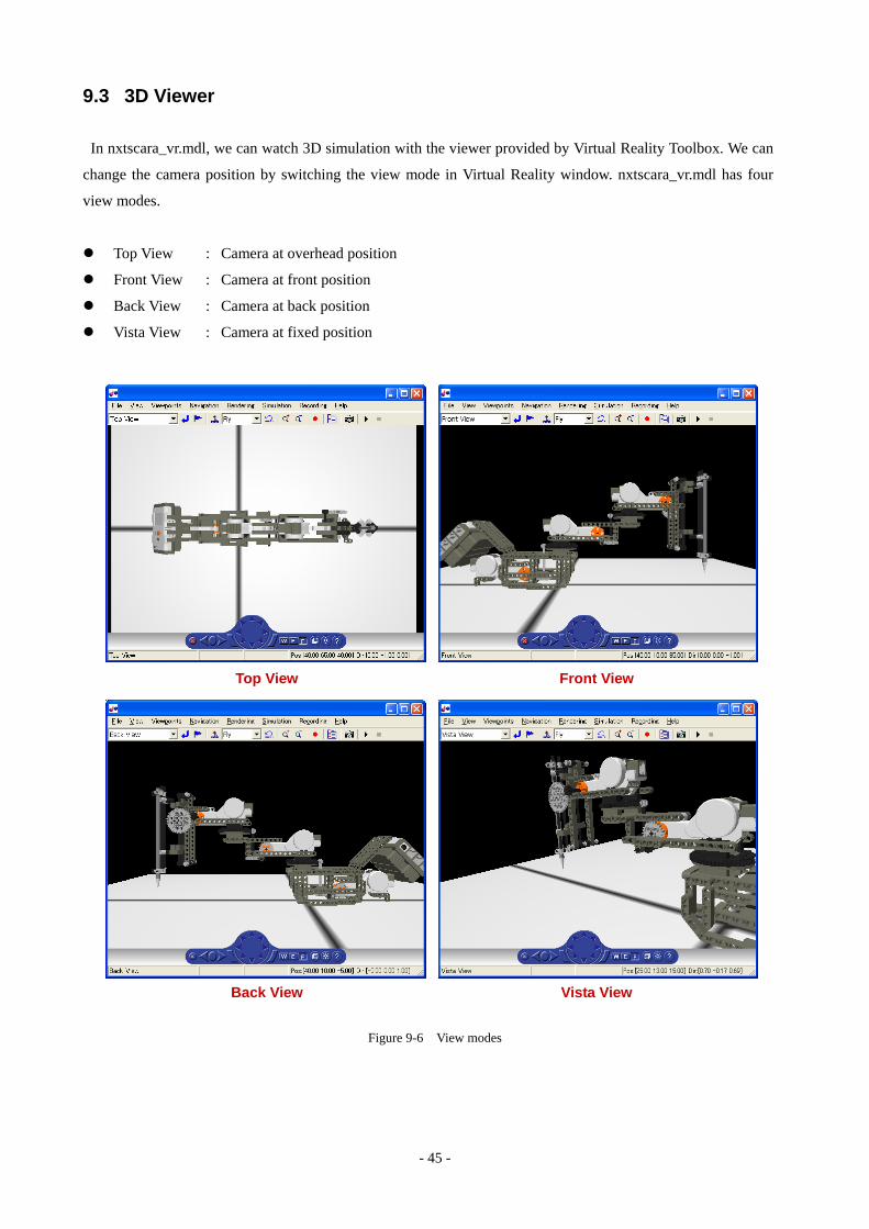
9.3 3D Viewer
In nxtscara_vr.mdl, we can watch 3D simulation with the viewer provided by Virtual Reality Toolbox. We can
change the camera position by switching the view mode in Virtual Reality window. nxtscara_vr.mdl has four
view modes.
Top View : Camera at overhead position
Front View : Camera at front position
Back View : Camera at back position
Vista View : Camera at fixed position
Top View Front View
Back View Vista View
Figure 9-6 View modes
- 46 -
10 Code Generation and Implementation
This chapter describes how to generate code from nxtscara_controller.mdl and download it into NXT
Intelligent Brick. Also the experimental results are shown.
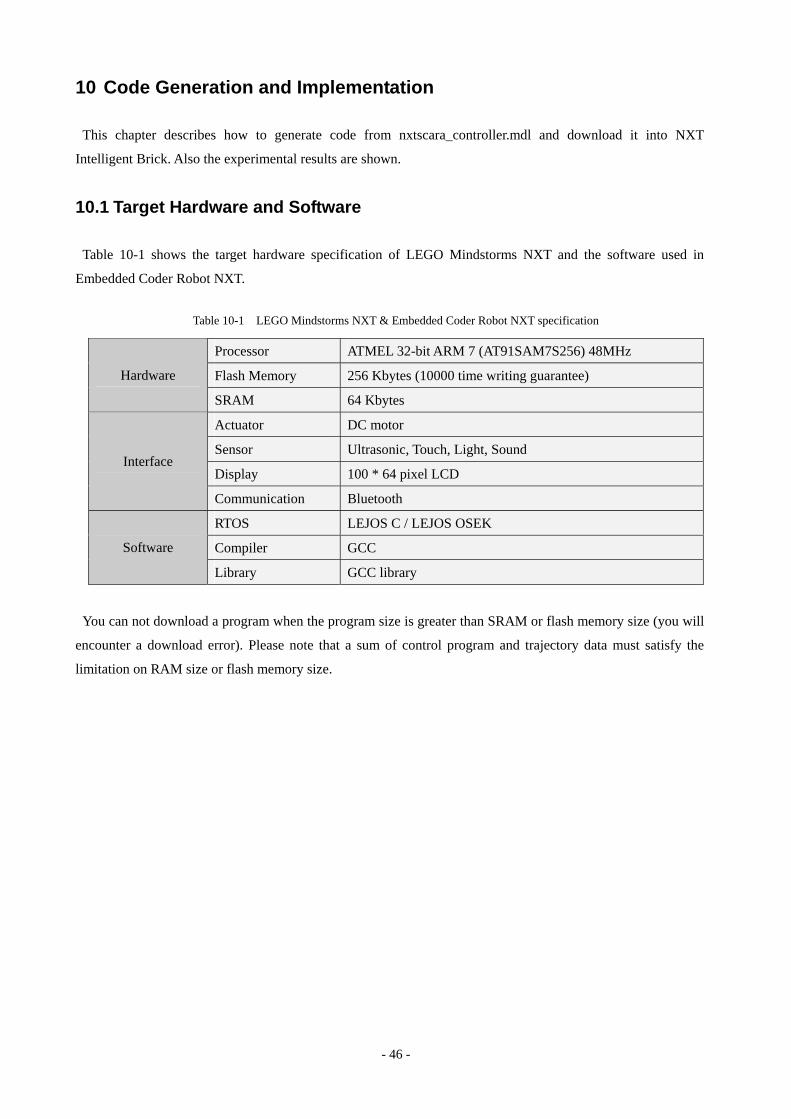
10.1 Target Hardware and Software
Table 10-1 shows the target hardware specification of LEGO Mindstorms NXT and the software used in
Embedded Coder Robot NXT.
Table 10-1 LEGO Mindstorms NXT & Embedded Coder Robot NXT specification
Processor ATMEL 32-bit ARM 7 (AT91SAM7S256) 48MHz
Flash Memory 256 Kbytes (10000 time writing guarantee) Hardware
SRAM 64 Kbytes
Actuator DC motor
Sensor Ultrasonic, Touch, Light, Sound
Display 100 * 64 pixel LCD Interface
Communication Bluetooth
RTOS LEJOS C / LEJOS OSEK
Compiler GCC Software
Library GCC library
You can not download a program when the program size is greater than SRAM or flash memory size (you will
encounter a download error). Please note that a sum of control program and trajectory data must satisfy the
limitation on RAM size or flash memory size.
- 47 -
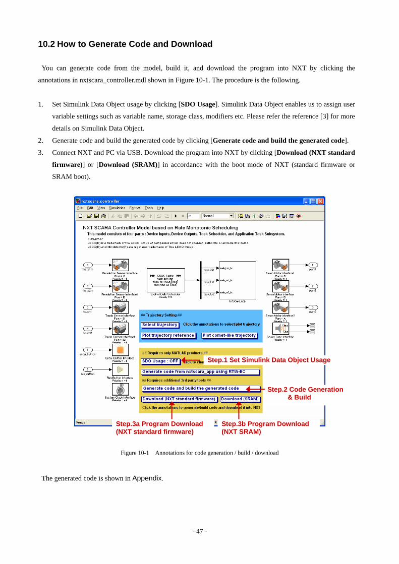
10.2 How to Generate Code and Download
You can generate code from the model, build it, and download the program into NXT by clicking the
annotations in nxtscara_controller.mdl shown in Figure 10-1. The procedure is the following.
1. Set Simulink Data Object usage by clicking [SDO Usage]. Simulink Data Object enables us to assign user
variable settings such as variable name, storage class, modifiers etc. Please refer the reference [3] for more
details on Simulink Data Object.
2. Generate code and build the generated code by clicking [Generate code and build the generated code].
3. Connect NXT and PC via USB. Download the program into NXT by clicking [Download (NXT standard
firmware)] or [Download (SRAM)] in accordance with the boot mode of NXT (standard firmware or
SRAM boot).
Step.1 Set Simulink Data Object Usage
Step.2 Code Generation & Build
Step.3a Program Download (NXT standard firmware)
Step.3b Program Download (NXT SRAM)
Figure 10-1 Annotations for code generation / build / download
The generated code is shown in Appendix.
- 48 -
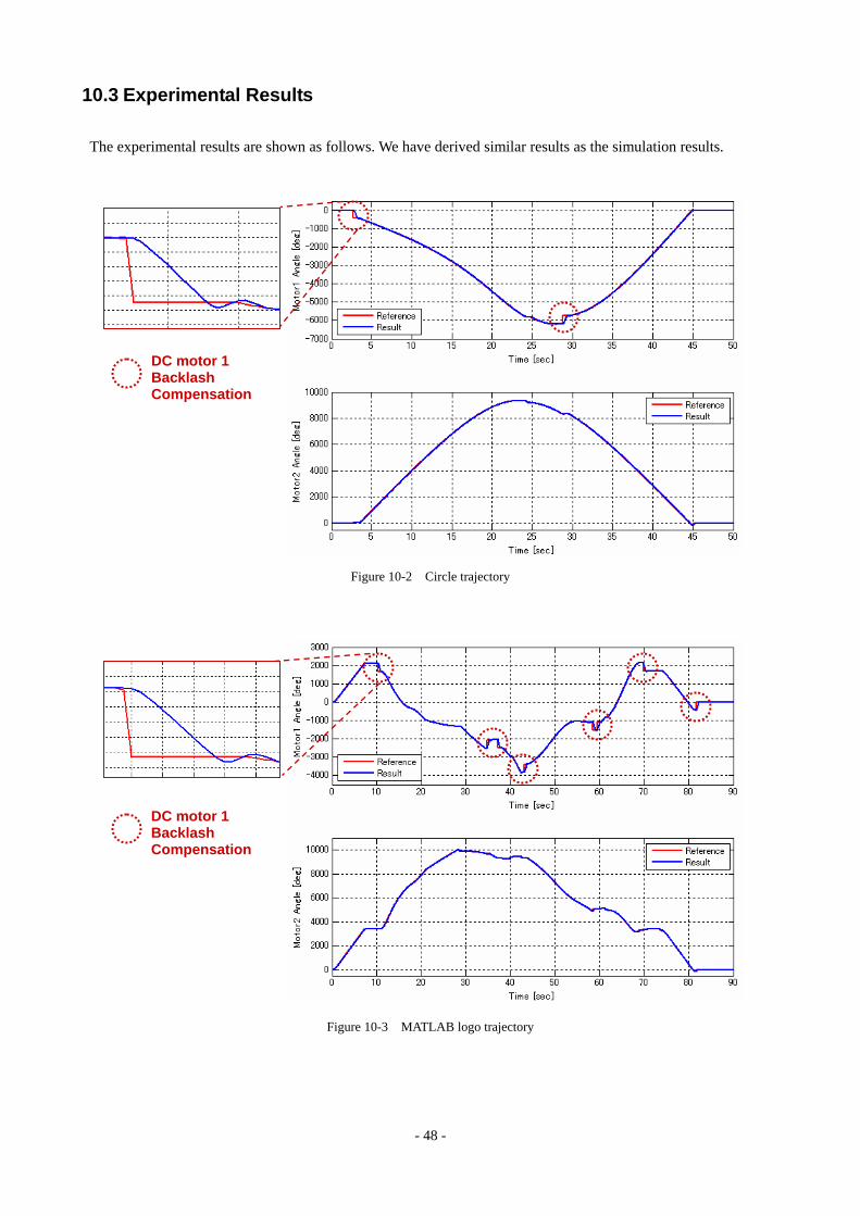
10.3 Experimental Results
The experimental results are shown as follows. We have derived similar results as the simulation results.
DC motor 1 Backlash Compensation
Figure 10-2 Circle trajectory
Figure 10-3 MATLAB logo trajectory
DC motor 1 Backlash Compensation
- 49 -
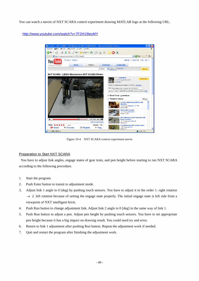
You can watch a movie of NXT SCARA control experiment drawing MATLAB logo at the following URL.
http://www.youtube.com/watch?v=7F2H19teyMY
Figure 10-4 NXT SCARA control experiment movie
Preparation to Start NXT SCARA
You have to adjust link angles, engage states of gear train, and pen height before starting to run NXT SCARA
according to the following procedure.
1. Start the program.
2. Push Enter button to transit to adjustment mode.
3. Adjust link 1 angle to 0 [deg] by pushing touch sensors. You have to adjust it in the order 1. right rotation
2. left rotation because of setting the engage state properly. The initial engage state is left side from a
viewpoint of NXT intelligent brick.
→
4. Push Run button to change adjustment link. Adjust link 2 angle to 0 [deg] in the same way of link 1.
5. Push Run button to adjust a pen. Adjust pen height by pushing touch sensors. You have to set appropriate
pen height because it has a big impact on drawing result. You could need try and error.
6. Return to link 1 adjustment after pushing Run button. Repeat the adjustment work if needed.
7. Quit and restart the program after finishing the adjustment work.

- 50 -
11 Challenges for Readers
We provide the following problems as challenges for readers. Try them if you are interested in.
Controller performance improvement (gain tuning, controller logic improvement, etc.)
Making new trajectory
Calculation and simulation of NXT SCARA motion equations
NXT SCARA hardware mechanism refinement
- 51 -
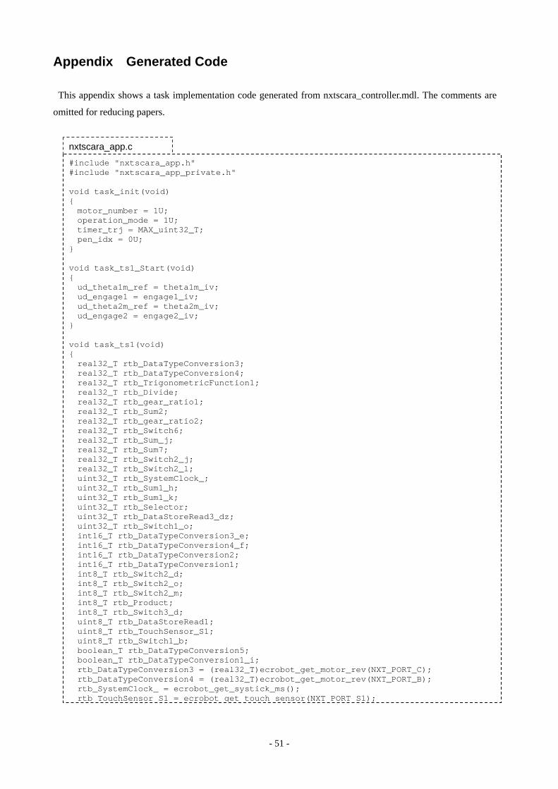
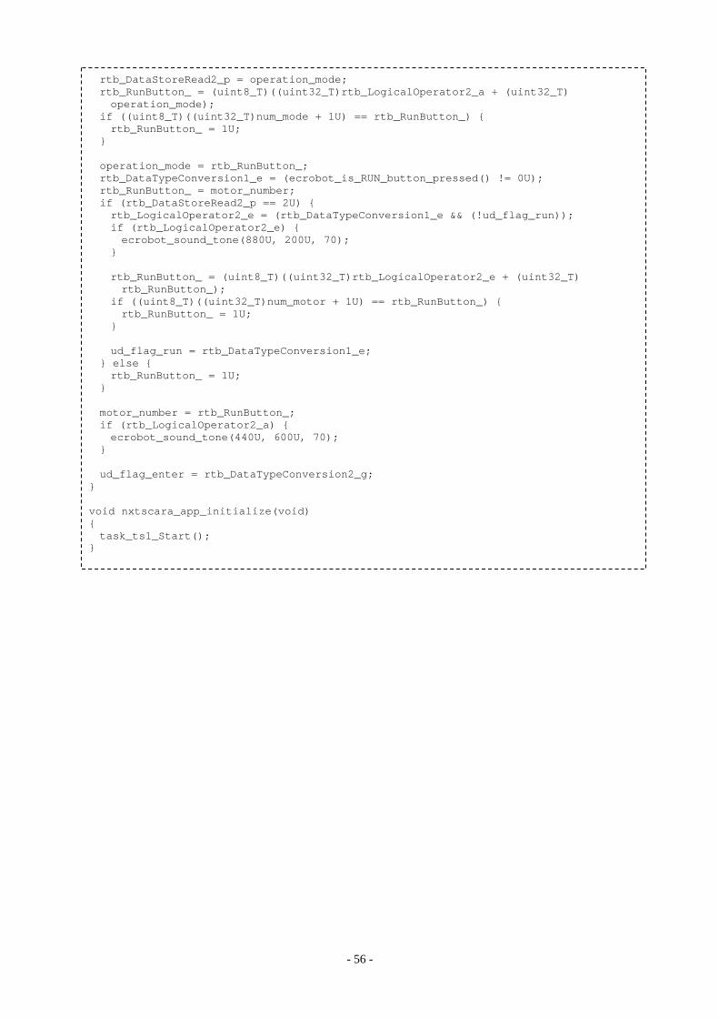
Appendix Generated Code
This appendix shows a task implementation code generated from nxtscara_controller.mdl. The comments are
omitted for reducing papers.
nxtscara_app.c #include "nxtscara_app.h" #include "nxtscara_app_private.h" void task_init(void) { motor_number = 1U; operation_mode = 1U; timer_trj = MAX_uint32_T; pen_idx = 0U; } void task_ts1_Start(void) { ud_theta1m_ref = theta1m_iv; ud_engage1 = engage1_iv; ud_theta2m_ref = theta2m_iv; ud_engage2 = engage2_iv; } void task_ts1(void) { real32_T rtb_DataTypeConversion3; real32_T rtb_DataTypeConversion4; real32_T rtb_TrigonometricFunction1; real32_T rtb_Divide; real32_T rtb_gear_ratio1; real32_T rtb_Sum2; real32_T rtb_gear_ratio2; real32_T rtb_Switch6; real32_T rtb_Sum_j; real32_T rtb_Sum7; real32_T rtb_Switch2_j; real32_T rtb_Switch2_l; uint32_T rtb_SystemClock_; uint32_T rtb_Sum1_h; uint32_T rtb_Sum1_k; uint32_T rtb_Selector; uint32_T rtb_DataStoreRead3_dz; uint32_T rtb_Switch1_o; int16_T rtb_DataTypeConversion3_e; int16_T rtb_DataTypeConversion4_f; int16_T rtb_DataTypeConversion2; int16_T rtb_DataTypeConversion1; int8_T rtb_Switch2_d; int8_T rtb_Switch2_o; int8_T rtb_Switch2_m; int8_T rtb_Product; int8_T rtb_Switch3_d; uint8_T rtb_DataStoreRead1; uint8_T rtb_TouchSensor_S1; uint8_T rtb_Switch1_b; boolean_T rtb_DataTypeConversion5; boolean_T rtb_DataTypeConversion1_i; rtb_DataTypeConversion3 = (real32_T)ecrobot_get_motor_rev(NXT_PORT_C); rtb_DataTypeConversion4 = (real32_T)ecrobot_get_motor_rev(NXT_PORT_B); rtb_SystemClock_ = ecrobot_get_systick_ms(); rtb TouchSensor S1 = ecrobot get touch sensor(NXT PORT S1);
- 52 -
rtb_DataTypeConversion5 = (ecrobot_get_touch_sensor(NXT_PORT_S1) != 0U); rtb_DataTypeConversion1_i = (ecrobot_get_touch_sensor(NXT_PORT_S2) != 0U); if (operation_mode == 1U) { if (timer_trj > time_finish) { if (rtb_DataTypeConversion5) { rtb_SystemClock_ = 0U; } else { rtb_SystemClock_ = MAX_uint32_T; } timer_trj = rtb_SystemClock_; pen_idx = 0U; rtb_Switch2_m = 0; rtb_Switch2_o = 0; rtb_Switch2_d = 0; } else { rtb_DataStoreRead3_dz = timer_trj; rtb_Switch1_o = timer_trj / 50U; { uint32_T rt_uClip = rtb_Switch1_o; rt_uClip = rt_MIN(rt_uClip,804); rtb_Sum7 = y_ref[rt_uClip]; } { uint32_T rt_uClip = rtb_Switch1_o; rt_uClip = rt_MIN(rt_uClip,804); rtb_Switch2_j = x_ref[rt_uClip]; } rtb_TrigonometricFunction1 = rt_atan232(rtb_Sum7, rtb_Switch2_j); rtb_Switch2_j = rtb_Switch2_j * rtb_Switch2_j + rtb_Sum7 * rtb_Sum7; rtb_Sum7 = 1.392399985E-002F; rtb_Divide = 4.0F * rtb_Switch2_j * rtb_Sum7; rtb_Switch2_j -= 1.849600114E-002F; rtb_Sum_j = rtb_Switch2_j + rtb_Sum7; rtb_Switch2_l = fabsf(rtb_Divide - rtb_Sum_j * rtb_Sum_j); if (rtb_Switch2_l < 0.0F) { rtb_Switch2_l = -sqrtf(-rtb_Switch2_l); } else { rtb_Switch2_l = sqrtf(rtb_Switch2_l); } rtb_gear_ratio1 = (rtb_TrigonometricFunction1 - rt_atan232(rtb_Switch2_l, rtb_Sum_j)) * 5.729578018E+001F * 84.0F; rtb_Sum2 = rtb_gear_ratio1 + ud_backlash1; theta1m_ref_bl = rtb_Sum2; if (rtb_DataStoreRead3_dz < (uint32_T)((int32_T)time_finish - (int32_T) time_wait)) { rtb_Sum_j = rtb_gear_ratio1 - ud_theta1m_ref; rtb_DataTypeConversion5 = (fabsf(rtb_Sum_j) > dthetam_bl); if ((ud_engage1 == -1) && (rtb_Sum_j > 0.0F) && rtb_DataTypeConversion5) { rtb_Sum_j = backlash1; } else { if (rtb_DataTypeConversion5 && (rtb_Sum_j < 0.0F) && (ud_engage1 == 1))
{ rtb_Sum_j = -backlash1; } else {
rtb_Sum_j = 0.0F; }
} } else { if (ud_engage1 == engage1_iv) { rtb_Sum_j = 0.0F; } else { if (engage1_iv == 1) { rtb_Sum_j = backlash1;
- 53 -
} else { rtb_Sum_j = -backlash1;
} } } if (rtb_Sum_j == 0.0F) {
rtb_Switch3_d = 1; } else {
rtb_Switch3_d = -1; } rtb_Product = (int8_T)(rtb_Switch3_d * ud_engage1); rtb_Divide = rtb_Sum7 * 1.849600114E-002F * 4.0F; rtb_Sum7 = rtb_Switch2_j - rtb_Sum7; rtb_Switch2_l = fabsf(rtb_Divide - rtb_Sum7 * rtb_Sum7);
if (rtb_Switch2_l < 0.0F) { rtb_Switch2_l = -sqrtf(-rtb_Switch2_l);
} else { rtb_Switch2_l = sqrtf(rtb_Switch2_l); } rtb_gear_ratio2 = 5.729578018E+001F * rt_atan232(rtb_Switch2_l, rtb_Sum7) *
84.0F; rtb_TrigonometricFunction1 = rtb_gear_ratio2 + ud_backlash2;
theta2m_ref_bl = rtb_TrigonometricFunction1; if (rtb_DataStoreRead3_dz < (uint32_T)((int32_T)time_finish - (int32_T) time_wait)) { rtb_Divide = rtb_gear_ratio2 - ud_theta2m_ref; rtb_DataTypeConversion5 = (fabsf(rtb_Divide) > dthetam_bl);
if ((ud_engage2 == -1) && (rtb_Divide > 0.0F) && rtb_DataTypeConversion5) {
rtb_Switch6 = backlash2; } else { if (rtb_DataTypeConversion5 && (rtb_Divide < 0.0F) && (ud_engage2 == 1)) { rtb_Switch6 = -backlash2;
} else { rtb_Switch6 = 0.0F;
} } } else { if (ud_engage2 == engage2_iv) { rtb_Switch6 = 0.0F; } else { if (engage2_iv == 1) {
rtb_Switch6 = backlash2; } else {
rtb_Switch6 = -backlash2; } } }
if (rtb_Switch6 == 0.0F) { rtb_Switch3_d = 1;
} else { rtb_Switch3_d = -1; } if ((rtb_DataTypeConversion3 < theta1m_max) && (rtb_DataTypeConversion3 >
-theta1m_max)) { rtb_Divide = (rtb_Sum2 - rtb_DataTypeConversion3) / 50.0F;
rtb_Divide = pwm1_offset * rt_FSGN(rtb_Divide) + pwm1_gain * rtb_Divide; rtb_Switch2_l = rt_SATURATE(rtb_Divide, -100.0F, 100.0F); } else { rtb_Switch2_l = -100.0F * rt_FSGN(rtb_DataTypeConversion3); } if ((rtb_DataTypeConversion4 < theta2m_max) && (rtb_DataTypeConversion4 >
- 54 -
-theta2m_max)) { rtb_Divide = (rtb_TrigonometricFunction1 - rtb_DataTypeConversion4) /
50.0F; rtb_Divide = pwm2_offset * rt_FSGN(rtb_Divide) + pwm2_gain * rtb_Divide; rtb_Switch2_j = rt_SATURATE(rtb_Divide, -100.0F, 100.0F); } else { rtb_Switch2_j = -100.0F * rt_FSGN(rtb_DataTypeConversion4);
}
rtb_Sum1_h = rtb_SystemClock_ + time_en1; if (rtb_Sum_j != 0.0F) { timer_en1_0 = rtb_Sum1_h; } rtb_Sum1_k = rtb_SystemClock_ + time_en2; if (rtb_Switch6 != 0.0F) {
timer_en2_0 = rtb_Sum1_k; }
rtb_SystemClock_ += time_pen; rtb_DataStoreRead1 = pen_idx; if (pen_idx <= 1U) { rtb_Switch1_o = time_table_pen[(int32_T)pen_idx];
} else { rtb_Switch1_o = MAX_uint32_T;
} rtb_DataTypeConversion5 = (rtb_Switch1_o == rtb_DataStoreRead3_dz); if (rtb_DataTypeConversion5 && (!ud_flag_pen)) { timer_pen_0 = rtb_SystemClock_;
}
rtb_Selector = (uint32_T)((int32_T)rtb_SystemClock_ - (int32_T)timer_pen_0); if (((uint32_T)((int32_T)rtb_Sum1_h - (int32_T)timer_en1_0) >= time_en1) && ((uint32_T)((int32_T)rtb_Sum1_k - (int32_T)timer_en2_0) >= time_en2) && (rtb_Selector >= time_pen)) { rtb_SystemClock_ = 50U;
} else { rtb_SystemClock_ = 0U;
} timer_trj = rtb_SystemClock_ + rtb_DataStoreRead3_dz; if (rtb_DataStoreRead3_dz == rtb_Switch1_o) { rtb_Switch1_b = 1U; } else { rtb_Switch1_b = 0U;
}
pen_idx = (uint8_T)((uint32_T)rtb_Switch1_b + (uint32_T)pen_idx); rtb_Switch2_m = (int8_T)floor((real_T)rtb_Switch2_l + 0.5); rtb_Switch2_o = (int8_T)floor((real_T)rtb_Switch2_j + 0.5); if (rtb_Selector <= time_wait) { rtb_Switch2_d = 0;
} else { if (rtb_Selector <= time_wait + time_pwm3) {
rtb_DataStoreRead1 %= 2U; if (rtb_DataStoreRead1 == 0U) { rtb_Switch2_d = pwm3_pen; } else { rtb_Switch2_d = (int8_T)(-pwm3_pen);
} } else {
rtb_Switch2_d = 0; } } ud_backlash1 = rtb_Sum_j + ud_backlash1; ud_theta1m_ref = rtb_gear_ratio1; ud_engage1 = rtb_Product;
- 55 -
ud_backlash2 = rtb_Switch6 + ud_backlash2; ud_theta2m_ref = rtb_gear_ratio2;
ud_engage2 = (int8_T)(rtb_Switch3_d * ud_engage2); ud_flag_pen = rtb_DataTypeConversion5; } } else { if (motor_number == 1U) {
if (rtb_DataTypeConversion5) { rtb_Switch2_m = pwm1_adjst;
} else { if (rtb_DataTypeConversion1_i) { rtb_Switch2_m = (int8_T)(-pwm1_adjst); } else { rtb_Switch2_m = 0; } }
rtb_Switch2_o = 0;
rtb_Switch2_d = 0; } else if (motor_number == 2U) { rtb_Switch2_m = 0; if (rtb_DataTypeConversion5) { rtb_Switch2_o = pwm2_adjst;
} else { if (rtb_DataTypeConversion1_i) {
rtb_Switch2_o = (int8_T)(-pwm2_adjst); } else { rtb_Switch2_o = 0; } }
rtb_Switch2_d = 0;
} else { rtb_Switch2_m = 0; rtb_Switch2_o = 0; if (rtb_DataTypeConversion5) { rtb_Switch2_d = pwm3_adjst;
} else { if (rtb_DataTypeConversion1_i) {
rtb_Switch2_d = (int8_T)(-pwm3_adjst); } else { rtb_Switch2_d = 0; } } } }
ecrobot_set_motor_mode_speed(NXT_PORT_C, 1, rtb_Switch2_m);
ecrobot_set_motor_mode_speed(NXT_PORT_B, 1, rtb_Switch2_o); ecrobot_set_motor_mode_speed(NXT_PORT_A, 1, rtb_Switch2_d); rtb_DataTypeConversion3_e = (int16_T)rtb_TouchSensor_S1; rtb_DataTypeConversion4_f = (int16_T)rt_MIN(timer_trj, 32767U); rtb_DataTypeConversion2 = (int16_T)floor((real_T)theta1m_ref_bl + 0.5);
rtb_DataTypeConversion1 = (int16_T)floor((real_T)theta2m_ref_bl + 0.5); ecrobot_bt_adc_data_logger(0, 0, rtb_DataTypeConversion3_e,
rtb_DataTypeConversion4_f, rtb_DataTypeConversion2, rtb_DataTypeConversion1); } void task_ts2(void) {
uint8_T rtb_DataStoreRead2_p; uint8_T rtb_RunButton_;
boolean_T rtb_DataTypeConversion2_g; boolean_T rtb_LogicalOperator2_a; boolean_T rtb_DataTypeConversion1_e; boolean_T rtb_LogicalOperator2_e; rtb_DataTypeConversion2_g = (ecrobot_is_ENTER_button_pressed() != 0U); rtb_LogicalOperator2_a = (rtb_DataTypeConversion2_g && (!ud_flag_enter) && (timer_trj == MAX_uint32_T));
- 56 -
rtb_DataStoreRead2_p = operation_mode; rtb_RunButton_ = (uint8_T)((uint32_T)rtb_LogicalOperator2_a + (uint32_T)
operation_mode); if ((uint8_T)((uint32_T)num_mode + 1U) == rtb_RunButton_) { rtb_RunButton_ = 1U; }
operation_mode = rtb_RunButton_; rtb_DataTypeConversion1_e = (ecrobot_is_RUN_button_pressed() != 0U);
rtb_RunButton_ = motor_number; if (rtb_DataStoreRead2_p == 2U) { rtb_LogicalOperator2_e = (rtb_DataTypeConversion1_e && (!ud_flag_run)); if (rtb_LogicalOperator2_e) { ecrobot_sound_tone(880U, 200U, 70); }
rtb_RunButton_ = (uint8_T)((uint32_T)rtb_LogicalOperator2_e + (uint32_T) rtb_RunButton_);
if ((uint8_T)((uint32_T)num_motor + 1U) == rtb_RunButton_) { rtb_RunButton_ = 1U; } ud_flag_run = rtb_DataTypeConversion1_e;
} else { rtb_RunButton_ = 1U;
} motor_number = rtb_RunButton_; if (rtb_LogicalOperator2_a) { ecrobot_sound_tone(440U, 600U, 70);
}
ud_flag_enter = rtb_DataTypeConversion2_g; } void nxtscara_app_initialize(void) {
task_ts1_Start(); }
- 57 -
References
[1] Philo’s Home Page LEGO Mindstorms NXT
http://www.philohome.com/
[2] Inverse Kinematics (Wikipedia)
http://en.wikipedia.org/wiki/Inverse_kinematics
[3] Real-Time Workshop Embedded Coder document
http://www.mathworks.com/access/helpdesk/help/toolbox/ecoder/