Embed Size (px)
Citation preview
MARCH 2006 IEEE Robotics & Automation Magazine 851070-9932/06/$20.00©2006 IEEE
P R A C T I T I O N E R ’ S C O R N E R
Object Capture witha Camera-Mobile
Robot SystemBY ROBERT J. WEBSTER III
This article describes a mobile robot/camera system thatis both simple and inexpensive enough for an under-graduate engineering student to construct. It provides
an excellent first introduction to hands-on robotics, enablingthe capture of small objects with the robot. It is scalable andcan lead the interested student further into many diverse areasof robotics research. We have carefully designed and arrangedcomponents so that the system can work with straightforwardalgorithms, off-the-shelf hardware, and minimal programming.Creating a working robot system not only introduces thebeginning roboticist to many interesting problems in roboticsbut also creates a testbed to begin exploring them.
Why Build A Mobile Robot System?Mobile robots are able to do more today than ever before,thanks to recent technical advances and cost reductions. Theyare often used in situations that are dangerous for humans,such as bomb disposal and detonation [4], rescuing disastervictims (e.g., 2001 World Trade Center) [3], decontaminat-ing highly radioactive environments (e.g., Chernobyl) [1], oreven vacuuming your rug [9]. The potential of robots toaccomplish such tasks depends on how well they can locateand interact with objects in their environments.
If one has never before attempted a robotics project,building and using a mobile robot may seem prohibitivelycomplex and difficult. However, armed with this article,the beginning roboticist can create a straightforward andinexpensive mobile robot/vision system able to locate andcapture objects near it.
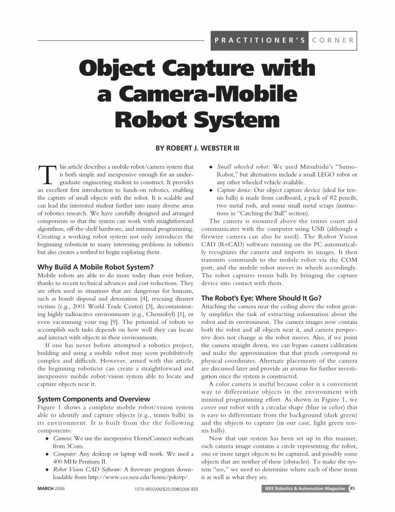
System Components and OverviewFigure 1 shows a complete mobile robot/vision systemable to identify and capture objects (e.g., tennis balls) inits environment. It is built from the the following components:
◆ Camera: We use the inexpensive HomeConnect webcamfrom 3Com.
◆ Computer: Any desktop or laptop will work. We used a400 MHz Pentium II.
◆ Robot Vision CAD Software: A freeware program down-loadable from http://www.ccs.neu.edu/home/psksvp/.
◆ Small wheeled robot: We used Mitsubishi’s “Sumo-Robot,” but alternatives include a small LEGO robot orany other wheeled vehicle available.
◆ Capture device: Our object capture device (ideal for ten-nis balls) is made from cardboard, a pack of #2 pencils,two metal rods, and some small metal scraps (instruc-tions in “Catching the Ball” section).
The camera is mounted above the tennis court andcommunicates with the computer using USB (although afirewire camera can also be used). The Robot VisionCAD (RvCAD) software running on the PC automatical-ly recognizes the camera and imports its images. It thentransmits commands to the mobile robot via the COMport, and the mobile robot moves its wheels accordingly.The robot captures tennis balls by bringing the capturedevice into contact with them.
The Robot’s Eye: Where Should It Go?Attaching the camera near the ceiling above the robot great-ly simplifies the task of extracting information about therobot and its environment. The camera images now containboth the robot and all objects near it, and camera perspec-tive does not change as the robot moves. Also, if we pointthe camera straight down, we can bypass camera calibrationand make the approximation that that pixels correspond tophysical coordinates. Alternate placements of the cameraare discussed later and provide an avenue for further investi-gation once the system is constructed.
A color camera is useful because color is a convenientway to differentiate objects in the environment withminimal programming effort. As shown in Figure 1, wecover our robot with a circular shape (blue in color) thatis easy to differentiate from the background (dark green)and the objects to capture (in our case, light green ten-nis balls).
Now that our system has been set up in this manner,each camera image contains a circle representing the robot,one or more target objects to be captured, and possibly someobjects that are neither of these (obstacles). To make the sys-tem “see,” we need to determine where each of these itemsis as well as what they are.
IEEE Robotics & Automation Magazine MARCH 200686
Making the Robot SeeMachine vision and image processing are very broad areas ofresearch, and there is an ever-growing number of creative anduseful methods for retrieving information from images. Manyof these are quite complex, but what we desire here is a verysimple way to make the mobile robot see its environment. Ourmobile robot needs to know 1) where it is located, 2) whatdirection it is facing, 3) where the tennis ball target object(s) is,and 4) the location of any obstacles present.
The RvCAD software will automatically import the videostream from the Webcam, and it provides a simple graphicalinterface where one can “wire” together blocks that performdifferent image processing functions. We first use a colorthreshold (a function built into RvCAD) to decide which pixelscontain robot, tennis ball, background, or something else (an
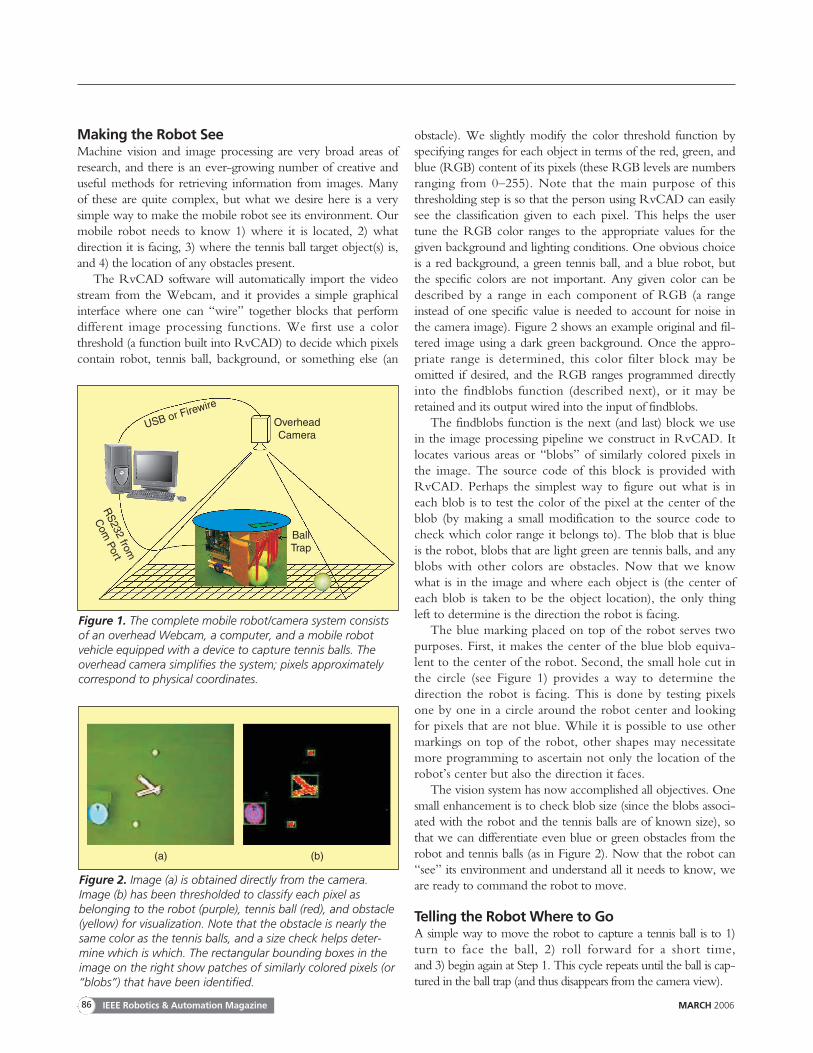
obstacle). We slightly modify the color threshold function byspecifying ranges for each object in terms of the red, green, andblue (RGB) content of its pixels (these RGB levels are numbersranging from 0–255). Note that the main purpose of thisthresholding step is so that the person using RvCAD can easilysee the classification given to each pixel. This helps the usertune the RGB color ranges to the appropriate values for thegiven background and lighting conditions. One obvious choiceis a red background, a green tennis ball, and a blue robot, butthe specific colors are not important. Any given color can bedescribed by a range in each component of RGB (a rangeinstead of one specific value is needed to account for noise inthe camera image). Figure 2 shows an example original and fil-tered image using a dark green background. Once the appro-priate range is determined, this color filter block may beomitted if desired, and the RGB ranges programmed directlyinto the findblobs function (described next), or it may beretained and its output wired into the input of findblobs.
The findblobs function is the next (and last) block we usein the image processing pipeline we construct in RvCAD. Itlocates various areas or “blobs” of similarly colored pixels inthe image. The source code of this block is provided withRvCAD. Perhaps the simplest way to figure out what is ineach blob is to test the color of the pixel at the center of theblob (by making a small modification to the source code tocheck which color range it belongs to). The blob that is blueis the robot, blobs that are light green are tennis balls, and anyblobs with other colors are obstacles. Now that we knowwhat is in the image and where each object is (the center ofeach blob is taken to be the object location), the only thingleft to determine is the direction the robot is facing.
The blue marking placed on top of the robot serves twopurposes. First, it makes the center of the blue blob equiva-lent to the center of the robot. Second, the small hole cut inthe circle (see Figure 1) provides a way to determine thedirection the robot is facing. This is done by testing pixelsone by one in a circle around the robot center and lookingfor pixels that are not blue. While it is possible to use othermarkings on top of the robot, other shapes may necessitatemore programming to ascertain not only the location of therobot’s center but also the direction it faces.
The vision system has now accomplished all objectives. Onesmall enhancement is to check blob size (since the blobs associ-ated with the robot and the tennis balls are of known size), sothat we can differentiate even blue or green obstacles from therobot and tennis balls (as in Figure 2). Now that the robot can“see” its environment and understand all it needs to know, weare ready to command the robot to move.
Telling the Robot Where to GoA simple way to move the robot to capture a tennis ball is to 1)turn to face the ball, 2) roll forward for a short time, and 3) begin again at Step 1. This cycle repeats until the ball is cap-tured in the ball trap (and thus disappears from the camera view).
Figure 1. The complete mobile robot/camera system consistsof an overhead Webcam, a computer, and a mobile robotvehicle equipped with a device to capture tennis balls. Theoverhead camera simplifies the system; pixels approximatelycorrespond to physical coordinates.
USB or Firewire
RS
232 from
Com
Port
OverheadCamera
BallTrap
Figure 2. Image (a) is obtained directly from the camera.Image (b) has been thresholded to classify each pixel asbelonging to the robot (purple), tennis ball (red), and obstacle(yellow) for visualization. Note that the obstacle is nearly thesame color as the tennis balls, and a size check helps deter-mine which is which. The rectangular bounding boxes in theimage on the right show patches of similarly colored pixels (or“blobs”) that have been identified.
(a) (b)
MARCH 2006 IEEE Robotics & Automation Magazine 87
How far and in which direction the robot should turn toface the ball can be determined by taking the cross product oftwo vectors based at the center of the robot. Vector A pointstoward the front of the robot, and vector B points toward thetennis ball. Solving the cross product formula for angle(θ = sin−1(|A × B|/|A||B|)) yields the angle the robot shouldturn. However, some ambiguity remains because the absolutevalues in the above formula mean θ will always be in the firstor fourth quadrants, even if the actual angle the robot shouldturn is greater than 90◦ in either direction. The correct anglecan be found by taking the dot product between the A and B.If the sign of the dot product is positive, the robot should turn θ degrees. If it is negative, then the robot should turn(180 − θ) degrees.
These calculations can be performed either on the PC oron the mobile robot’s microcontroller. We chose the latterbecause the Sumo-Robot has sufficient onboard processingpower. Whichever strategy is selected, information can betransmitted to the mobile robot by making a minor modifi-cation to the code in “findblobs” allowing it to write to theCOM port. If one is using an alternative to the Sumo-Robot, it may also be useful to consider using the comput-er’s parallel port to transmit data.
The mobile robot receives information from the PC andturns its wheels (one forward and one backward) so that it piv-ots about its center until it faces the tennis ball. As mentionedpreviously, it then drives forward a short distance before updat-ing its path. This closed-loop method of driving the robot tothe ball is robust in that it works even in the presence of robotwheel slippage, tennis ball motion, or multiple tennis balls (pro-vided the location of the ball closest to the robot is the oneselected as the target).
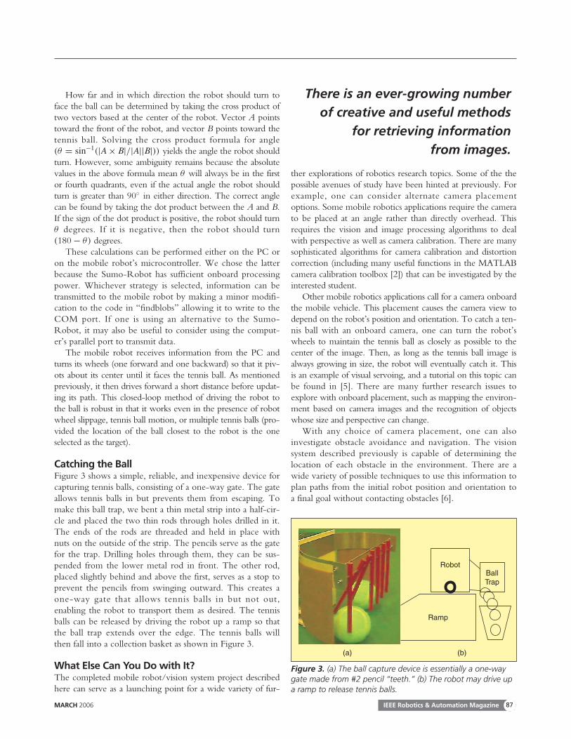
Catching the BallFigure 3 shows a simple, reliable, and inexpensive device forcapturing tennis balls, consisting of a one-way gate. The gateallows tennis balls in but prevents them from escaping. Tomake this ball trap, we bent a thin metal strip into a half-cir-cle and placed the two thin rods through holes drilled in it.The ends of the rods are threaded and held in place withnuts on the outside of the strip. The pencils serve as the gatefor the trap. Drilling holes through them, they can be sus-pended from the lower metal rod in front. The other rod,placed slightly behind and above the first, serves as a stop toprevent the pencils from swinging outward. This creates aone-way gate that allows tennis balls in but not out,enabling the robot to transport them as desired. The tennisballs can be released by driving the robot up a ramp so thatthe ball trap extends over the edge. The tennis balls willthen fall into a collection basket as shown in Figure 3.
What Else Can You Do with It?The completed mobile robot/vision system project describedhere can serve as a launching point for a wide variety of fur-
ther explorations of robotics research topics. Some of the thepossible avenues of study have been hinted at previously. Forexample, one can consider alternate camera placementoptions. Some mobile robotics applications require the camerato be placed at an angle rather than directly overhead. Thisrequires the vision and image processing algorithms to dealwith perspective as well as camera calibration. There are manysophisticated algorithms for camera calibration and distortioncorrection (including many useful functions in the MATLABcamera calibration toolbox [2]) that can be investigated by theinterested student.
Other mobile robotics applications call for a camera onboardthe mobile vehicle. This placement causes the camera view todepend on the robot’s position and orientation. To catch a ten-nis ball with an onboard camera, one can turn the robot’swheels to maintain the tennis ball as closely as possible to thecenter of the image. Then, as long as the tennis ball image isalways growing in size, the robot will eventually catch it. Thisis an example of visual servoing, and a tutorial on this topic canbe found in [5]. There are many further research issues toexplore with onboard placement, such as mapping the environ-ment based on camera images and the recognition of objectswhose size and perspective can change.
With any choice of camera placement, one can alsoinvestigate obstacle avoidance and navigation. The visionsystem described previously is capable of determining thelocation of each obstacle in the environment. There are awide variety of possible techniques to use this information toplan paths from the initial robot position and orientation toa final goal without contacting obstacles [6].
There is an ever-growing numberof creative and useful methods
for retrieving information from images.
Figure 3. (a) The ball capture device is essentially a one-waygate made from #2 pencil “teeth.” (b) The robot may drive upa ramp to release tennis balls.
BallTrap
Robot
Ramp
(a) (b)
IEEE Robotics & Automation Magazine MARCH 200688
Another broad research area that can be investigated withthis system is nonholonomic robotics. If, instead of simplycatching the tennis ball, we want the robot to approach itfrom a specific direction, a simple straight line path will nolonger be sufficient. The robot cannot slide sideways aroundthe ball as it approaches because its wheels impose a nonholo-nomic constraint that prevents sideways motion. However, itis intuitively clear that the robot can perform additionalmaneuvers (such as those needed when parallel parking anautomobile) to capture the ball from a specific desired direc-tion. A thorough treatment of nonholonomy can be found in[8], and an example directly applicable to the Sumo-Robotcan be found in [7, Ch. 2]. The unicycle example presentedthere is directly analogous to the two-wheeled Sumo-Robot.When operated as described here (so that it moves either in astraight line or pivots about its center), the Sumo-Robot hasthe same kinematic constraints as a unicycle.
The issues mentioned above are only a sampling of themany possible avenues of future research for the interested stu-dent. The challenges and interesting features of such endeavorshave the potential to inspire a student toward continued explo-ration in robotics.
ConclusionThe system described in here, known as the “Electronic BallBoy,” was developed at the University of Newcastle, Australia.Videos and additional information can be found in [10] and[11]. The system was constructed by two undergraduates withminimal experience in robotics and no prior computer visiontraining. The amount of time required was one semester, as asenior design project. As an introduction to robotics research,this project provides exposure to the fields of mobile robotics,image processing, hardware development, and system integra-tion. After the initial system is functional, it serves as a testbedfor further investigation and can be taken as far as the studentdesires. Constructing this system can be an excellent first intro-duction to hands-on robotics research.
AcknowledgmentsThis work could not have accomplished without Alan Brannon, who was involved in all phases of the Electronic Ball
Boy project. Rick Middleton and Ian Walker both contributedideas, and both Clemson University and the University of New-castle in Australia provided financial support for the project.
KeywordsMobile robotics, educational robotics, visual servoing.
References[1] J. Abouaf, “Trial by fire: Teleoperated robot targets Chernobyl,” IEEE
Comput Graph. Appl., vol. 18, no. 4, pp. 10–14, 1998.[2] J.-Y. Bouguet, “Camera calibration toolbox for Matlab,” [Online]. Avail-
able: http://www.vision. caltech.edu/bouguetj/calib_doc/index.html[3] J. Casper and R.R. Murphy, “Human-robot interactions during the robot-
assisted urban search and rescue response at the world trade center,” IEEETrans. Syst., Man, Cybern., vol. 33, no. 3, pp. 367–385, 2003.
[4] B.G. DeRoos, J.D. Price, and J.J. Reidy, “Law enforcement robot technol-ogy assessment,” Proc. SPIE, vol. 4232, 2001.
[5] S. Hutchinson, G.D. Hager, and P.I. Corke, “A tutorial on visual servocontrol,” IEEE Trans. Robot. Automat., vol. 12, no. 5, pp. 651–670, 1996.
[6] S.M. LaValle, Planning Algorithms. Cambridge Univ. Press, to be published. [7] M.T. Mason, Mechanics of Robotic Manipulation. Cambridge, MA: MIT
Press, 2001.[8] R.M. Murray, Z. Li, and S.S. Sastry, A Mathematical Introduction to Robotic
Manipulation. Ann Arbor MI: CRC Press, 1994.[9] G. Musser, “Robots that suck. Have they finally come out with a robot for
the rest of us?” Sci. Amer., vol. 288, no. 2, pp. 84–86, 2003.[10] R.J. Webster III and A.S. Brannon,” The electronic ballboy Mark III“
[Online]. Available: http://murray.newcastle.edu.au/users/students/2001/c2100098/ebb.html
[11] R.J. Webster, III and A.S. Brannon, “The electronic ball boy: A reactivevisually guided mobile robot for the tennis court,” in Proc. IEEE Int. Conf.Robot. Automat. (ICRA) 2002, pp. 2054–2059.
Robert J. Webster III is pursuing his Ph.D. in mechani-cal engineering at the Johns Hopkins University, where hereceived his M.S. in 2004. He received his B.S. in electri-cal engineering from Clemson University in 2002. He hasheld research positions in mobile and bioinspired roboticsat the University of Newcastle in Australia and at theSavanna River Site, respectively. His current dissertationresearch focuses on the design of miniature flexible medicalrobots. This includes steerable needles and active cannulasto reduce trauma and improve the accuracy of surgery.
Address for Correspondence: Robert Webster, Department ofMechanical Engineering, The Johns Hopkins University,223 Latrobe Hall, 3400 North Charles Street, Baltimore,MD 21218-2681 USA. Phone: +1 410 516 4184. Fax: +1410 516 7254. E-mail: [email protected]
Some mobile robotics applications require thecamera to be placed at an angle.