Embed Size (px)
Citation preview
Oblique detonation waves stabilized inrectangular-cross-section bent tubes
著者 Kudo Yusuke, Nagura Yuuto, Kasahara Jiro,Sasamoto Yuya, Matsuo Akiko
journal orpublication title
Proceedings of the Combustion Institute
volume 33number 2page range 2319-2326year 2011権利 (C) 2010 The Combustion Institute Published by
Elsevier Inc. NOTICE: this is the author’sversion of a work that was accepted forpublication in Proceedings of the CombustionInstitute. Changes resulting from thepublishing process, such as peer review,editing, corrections, structural formatting,and other quality control mechanisms may notbe reflected in this document. Changes mayhave been made to this work since it wassubmitted for publication. A definitiveversion was subsequently published inPUBLICATION, 33, 2, 2011, DOI:10.1016/j.proci.2010.08.008
URL http://hdl.handle.net/2241/113155doi: 10.1016/j.proci.2010.08.008
Proceedings of the Combustion Institute, Vol.33, 2011, pp.2319-2326 Y. Kudo, Y. Nagura, J. Kasahara, Y. Sasamoto, and A. Matsuo
1
Title : Oblique Detonation Waves Stabilized in Rectangular-Cross-Section Bent Tubes
Authors : YUSUKE KUDO 1 , YUUTO NAGURA 1, JIRO KASAHARA 1
YUYA SASAMOTO 2, AKIKO MATSUO 2
Affiliation 1 : Department of Engineering Mechanics and Energy, University of Tsukuba
1-1-1 Tennodai, Tsukuba 305-8573, Japan
Affiliation 2 : Department of Mechanical Engineering, Keio University
3-14-1 Hiyoshi, Kouhoku-ku, Yokohama 223-8522, Japan
Address :
JIRO KASAHARA, Department of Engineering Mechanics and Energy,
University of Tsukuba, 1-1-1 Tennodai, Tsukuba 305-8573, Japan
E-mail : [email protected]
Fax : 029-853-5267
Colloquium : DETONATIONS, EXPLOSIONS AND SUPERSONIC COMBUSTION
including pulse-detonation and scramjet engines
Total Length :
(Method : M1)
5981 words
Main text : 2243 words
Acknowledgements : 293 words
References : 404 words
Figures : 2785 words
Tables : 256 words
Proceedings of the Combustion Institute, Vol.33, 2011, pp.2319-2326 Y. Kudo, Y. Nagura, J. Kasahara, Y. Sasamoto, and A. Matsuo
2
Abstract
Oblique detonation waves, which are generated by a fundamental detonation phenomenon occurring in bent
tubes, may be applied to fuel combustion in high-efficiency engines such as a Pulse Detonation Engine (PDE) and
a Rotating Detonation Engine (RDE). The present study has experimentally demonstrated that steady-state
oblique detonation waves propagated stably through rectangular-cross-section bent tubes by visualizing these
waves using a high-speed camera and the shadowgraph method. The oblique detonation waves were stabilized
under the conditions of high initial pressure and a large curvature radius of the inside wall of the
rectangular-cross-section bent tube. The geometrical shapes of the stabilized oblique detonation waves were
calculated, and the results of the calculation were in good agreement with those of our experiment. Moreover, it
was experimentally shown that the critical condition under which steady-state oblique detonation waves can stably
propagate through the rectangular-cross-section bent tubes was the curvature radius of the inside wall of the
rectangular-cross-section bent tube equivalent to 14 to 40 times the cell width.
Keywords
Detonation Wave, Oblique Detonation Wave, Pulse Detonation Engine, Rotating Detonation Engine
Nomenclature
p0 = initial pressure
ri = curvature radius of the inside wall
VCJ = Chapman-Jouguet (CJ) detonation velocity
= analogy angle
= detonation cell size
= angle of detonation wave front
i = angle of detonation wave front on inside wall
= angular velocity of detonation wave front
i = angular velocity of detonation wave front on inside wall
1 Introduction
Oblique detonation waves, which are generated by a fundamental detonation phenomenon in bent tubes, may be
applied to fuel combustion in high-efficiency engines such as a Pulse Detonation Engine (PDE) (Kailasanath [1, 2],
Roy et al. [3], Kasahara et al. [4-6], Sato et al. [7], Endo et al. [8, 9]) and a Rotating Detonation Engine (RDE)
(Meredith et al. [10], Kindracki et al. [11], Jiang et al. [12], Yi et al. [13]). Many studies have been conducted on
oblique detonation waves, which are stably generated by flying particles projected together with a combustible
premixed gas (Kasahara et al. [14-17], Higgins [18-19], Lee [20], Kaneshige and Shepherd [21]). Oblique
detonation waves may be retained stably during propagation through rectangular-cross-section bent tubes with a
smaller inside wall area (or only by means of the linear motion of projectiles) than general planar detonation waves
generated in tubes with a constant cross section.
Based on the result of numerical analysis, Lee et al. [22] indicated the effects of curvature on the detonation
Proceedings of the Combustion Institute, Vol.33, 2011, pp.2319-2326 Y. Kudo, Y. Nagura, J. Kasahara, Y. Sasamoto, and A. Matsuo
3
wave propagation in annular channels and the critical curvature radius where the regular cell structure could be
maintained. Deflagration-to-Detonation-Transition (DDT) occurring in the U-bent tubes has been experimentally
revealed by Frolov et al. [23-24]. However, to our knowledge, no studies have reported steady-state oblique
detonation waves stably propagating through the bent tubes.
The present study experimentally demonstrated that steady-state oblique detonation waves propagated stably
through rectangular-cross-section bent tubes by visualizing the waves using a high-speed camera and the
shadowgraph method. Moreover, the shapes of the oblique detonation waves propagating through the rectangular
cross-section bent tubes and the critical curvature radiuses of the inside walls of the tubes were obtained.
The detonation diffracted from an open ended tube (Zel’dovich et al. [25], Matsui et al. [26], Mitrofanov and
Soloukhin [27], Edward et al. [28], Knystautas et al. [29], Murry and Lee [30], Meredith et al. [31], M. Arienti, J. E.
Shepherd [32]) is similar to that from bent tubes if an initial pressure of detonable mixture is sufficiently low, and
inside-wall curvature radius is sufficiently large, but such diffracted detonation wave propagation is not always
steady state. We focused on the stabilized detonation wave which could occur when the super critical condition was
satisfied (an initial pressure of detonable mixture is sufficiently high, and inside-wall curvature radius is
sufficiently small). This stabilized detonation wave is steady state in the two-dimensional polar coordinate in which
the z (polar)-axis has the same rotating frequency as the detonation waves.
2 Experiment
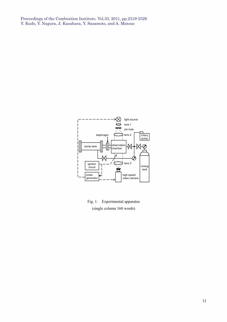
Figs. 1 and 2 show the schematic of our experimental apparatus and the observation chamber, respectively. The
observation chamber is composed of a rectangular cross-section bent tube 1, a circular cross-section straight tube 1,
and a circular cross-section straight tube 2. As shown in Fig. 2, the circular cross-section straight tube 1 has a 50
mm-length Shchelkin spiral and an igniter. The circular cross-section straight tube 2 is connected to a dump tank
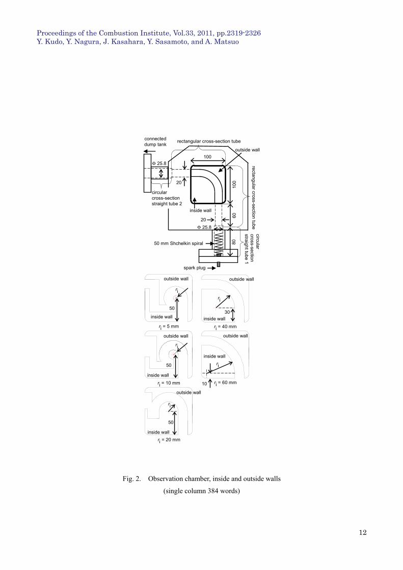
(0.037 m3) with a 12 m Mylar diaphragm between them. The inside and outside walls are fixed to the bold line
area of the inside of the observation chamber (upper part in Fig. 2) to form a rectangular-cross-section bent tube
with five kinds of curvature radiuses. In the upper part of Fig. 2, the rectangular-cross-section bent tube with an
inside wall of 40 mm in curvature radius and an outside wall of 60 mm in curvature radius, which changes by 90
degrees in its axial direction, is shown. The rectangular-cross-section bent tubes are 20 mm in width and 16 mm
in depth throughout their overall length.
The premixed gas filled in the observation chamber is ignited using a spark plug. Detonation waves are
generated in the circular cross-section straight tube 1 with a 25.8 mm inside diameter and propagated into the
rectangular-cross-section bent tube and then the circular cross-section straight tube 2. High pressure gas
generated by the detonation waves is discharged into the low-vacuum dump tank. The inside of the
rectangular-cross-section bent tube is visualized using the shadowgraph method, as shown in Fig. 1. Shimadzu
HPV-1 high-speed video camera was used.
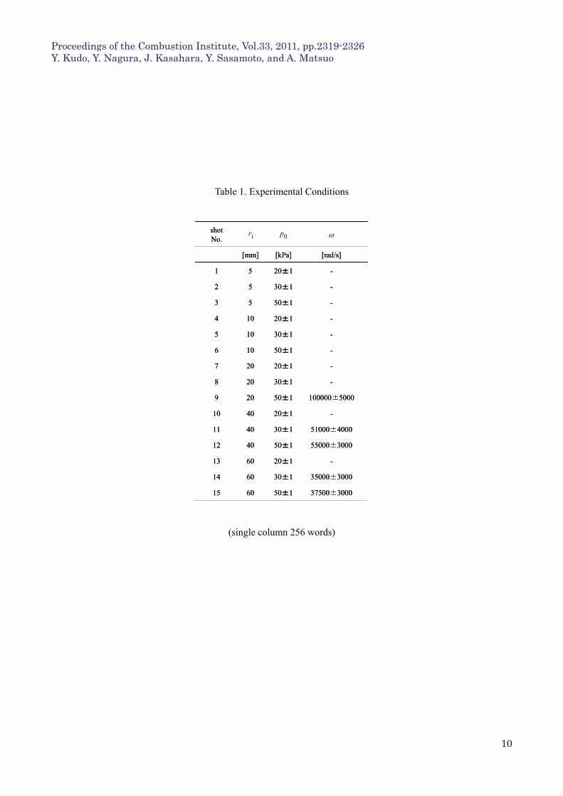
Rectangular-cross-section bent tubes with 5, 10, 20, 40, or 60 mm in curvature radius (ri ) of the inside wall were
used in our experiments, as shown in the lower part of Fig. 2. A stoichiometric ratio of ethylene-oxygen premixed
gas was filled under an initial pressure (p0) of 20, 30, or 50 kPa. Table 1 summarizes the experimental conditions.
We also carried out pressure measurements by using piezoelectric pressure sensors attached to the side channel wall
and checked whether the velocity determined by the pressure was identical to the velocity obtained from the
Proceedings of the Combustion Institute, Vol.33, 2011, pp.2319-2326 Y. Kudo, Y. Nagura, J. Kasahara, Y. Sasamoto, and A. Matsuo
4
high-speed camera. The results obtained showed that the velocity determined by the pressure was identical with
that from the camera within measurement error limits of 2 to 14%.
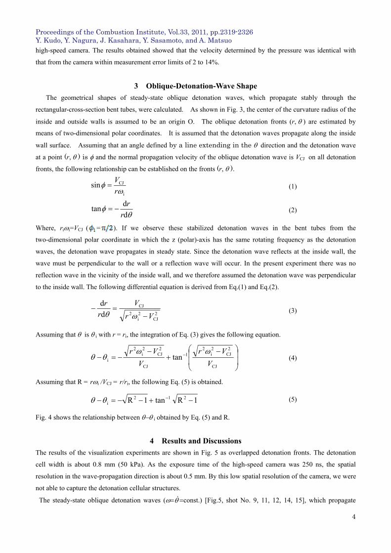
3 Oblique-Detonation-Wave Shape
The geometrical shapes of steady-state oblique detonation waves, which propagate stably through the
rectangular-cross-section bent tubes, were calculated. As shown in Fig. 3, the center of the curvature radius of the
inside and outside walls is assumed to be an origin O. The oblique detonation fronts (r,) are estimated by
means of two-dimensional polar coordinates. It is assumed that the detonation waves propagate along the inside
wall surface. Assuming that an angle defined by a line extending in the direction and the detonation wave
at a point (r,) is and the normal propagation velocity of the oblique detonation wave is VCJ on all detonation
fronts, the following relationship can be established on the fronts (r,).
i
CJsin
r
V (1)
d
dtan
r
r (2)
Where, rii=VCJ ( = ). If we observe these stabilized detonation waves in the bent tubes from the
two-dimensional polar coordinate in which the z (polar)-axis has the same rotating frequency as the detonation
waves, the detonation wave propagates in steady state. Since the detonation wave reflects at the inside wall, the
wave must be perpendicular to the wall or a reflection wave will occur. In the present experiment there was no
reflection wave in the vicinity of the inside wall, and we therefore assumed the detonation wave was perpendicular
to the inside wall. The following differential equation is derived from Eq.(1) and Eq.(2).
2CJ
2i
2
CJ
d
d
Vr
V
r
r
(3)
Assuming that is i with r = ri, the integration of Eq. (3) gives the following equation.
CJ
2CJ
2i
21
CJ
2CJ
2i
2
i tanV
Vr
V
Vr (4)
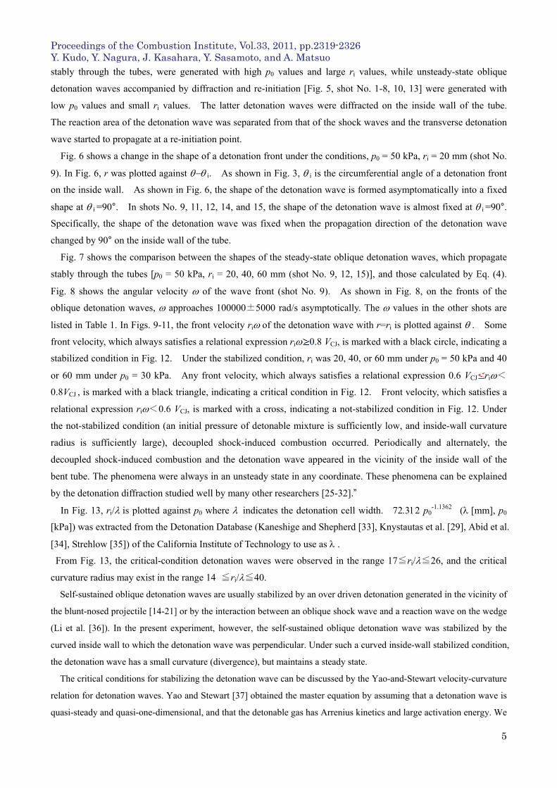
Assuming that R = ri /VCJ = r/ri, the following Eq. (5) is obtained.
1Rtan1R 212i (5)
Fig. 4 shows the relationship between i obtained by Eq. (5) and R.
4 Results and Discussions
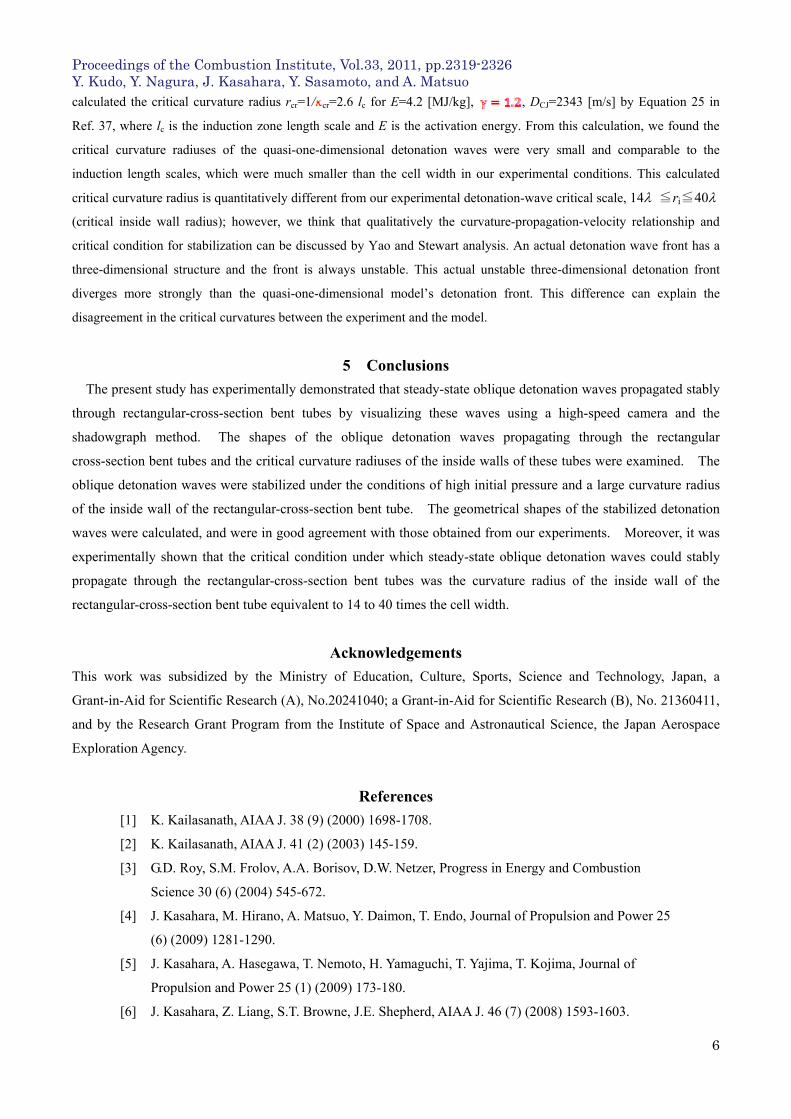
The results of the visualization experiments are shown in Fig. 5 as overlapped detonation fronts. The detonation
cell width is about 0.8 mm (50 kPa). As the exposure time of the high-speed camera was 250 ns, the spatial
resolution in the wave-propagation direction is about 0.5 mm. By this low spatial resolution of the camera, we were
not able to capture the detonation cellular structures.
The steady-state oblique detonation waves (const.) [Fig.5, shot No. 9, 11, 12, 14, 15], which propagate
Proceedings of the Combustion Institute, Vol.33, 2011, pp.2319-2326 Y. Kudo, Y. Nagura, J. Kasahara, Y. Sasamoto, and A. Matsuo
5
stably through the tubes, were generated with high p0 values and large ri values, while unsteady-state oblique
detonation waves accompanied by diffraction and re-initiation [Fig. 5, shot No. 1-8, 10, 13] were generated with
low p0 values and small ri values. The latter detonation waves were diffracted on the inside wall of the tube.
The reaction area of the detonation wave was separated from that of the shock waves and the transverse detonation
wave started to propagate at a re-initiation point.
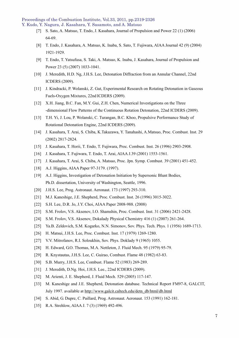
Fig. 6 shows a change in the shape of a detonation front under the conditions, p0 = 50 kPa, ri = 20 mm (shot No.
9). In Fig. 6, r was plotted against i. As shown in Fig. 3, i is the circumferential angle of a detonation front
on the inside wall. As shown in Fig. 6, the shape of the detonation wave is formed asymptomatically into a fixed
shape at i =90°. In shots No. 9, 11, 12, 14, and 15, the shape of the detonation wave is almost fixed at i =90°.
Specifically, the shape of the detonation wave was fixed when the propagation direction of the detonation wave
changed by 90° on the inside wall of the tube.
Fig. 7 shows the comparison between the shapes of the steady-state oblique detonation waves, which propagate
stably through the tubes [p0 = 50 kPa, ri = 20, 40, 60 mm (shot No. 9, 12, 15)], and those calculated by Eq. (4).
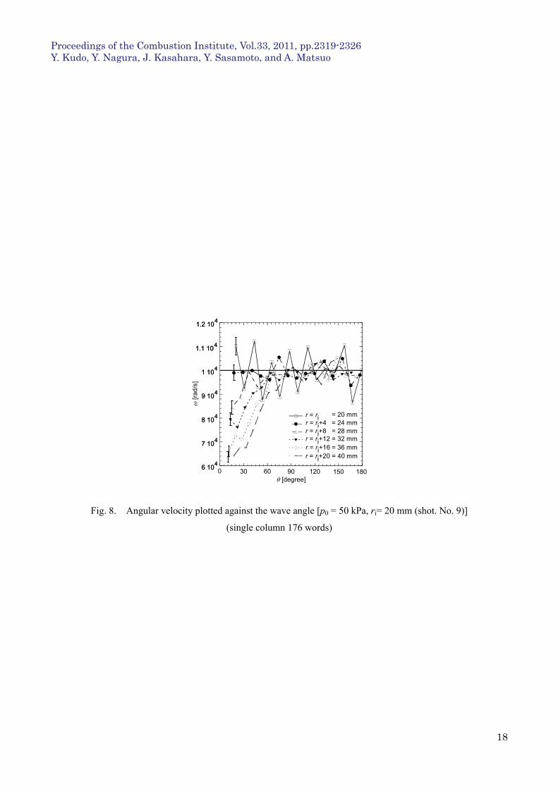
Fig. 8 shows the angular velocity of the wave front (shot No. 9). As shown in Fig. 8, on the fronts of the
oblique detonation waves, approaches 100000±5000 rad/s asymptotically. The values in the other shots are
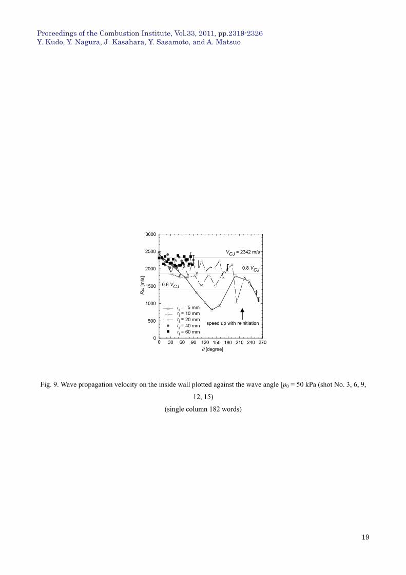
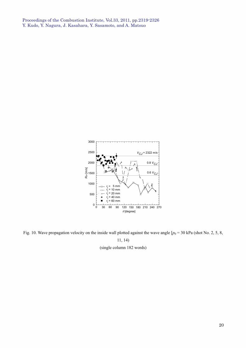
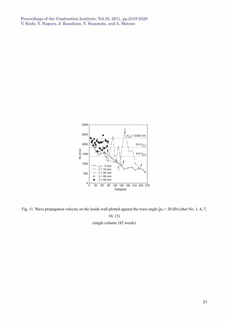
listed in Table 1. In Figs. 9-11, the front velocity riof the detonation wave with r=ri is plotted against . Some
front velocity, which always satisfies a relational expression ri 0.8 VCJ, is marked with a black circle, indicating a
stabilized condition in Fig. 12. Under the stabilized condition, ri was 20, 40, or 60 mm under p0 = 50 kPa and 40
or 60 mm under p0 = 30 kPa. Any front velocity, which always satisfies a relational expression 0.6 VCJ ri<
0.8VCJ , is marked with a black triangle, indicating a critical condition in Fig. 12. Front velocity, which satisfies a
relational expression ri<0.6 VCJ, is marked with a cross, indicating a not-stabilized condition in Fig. 12. Under
the not-stabilized condition (an initial pressure of detonable mixture is sufficiently low, and inside-wall curvature
radius is sufficiently large), decoupled shock-induced combustion occurred. Periodically and alternately, the
decoupled shock-induced combustion and the detonation wave appeared in the vicinity of the inside wall of the
bent tube. The phenomena were always in an unsteady state in any coordinate. These phenomena can be explained
by the detonation diffraction studied well by many other researchers [25-32].”
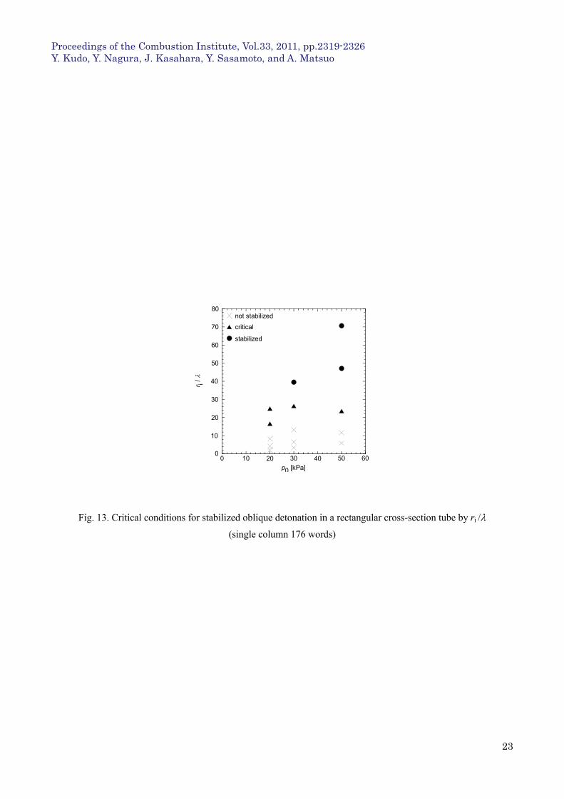
In Fig. 13, ri/is plotted against p0 where indicates the detonation cell width. p0-1.1362 ([mm], p0
[kPa]) was extracted from the Detonation Database (Kaneshige and Shepherd [33], Knystautas et al. [29], Abid et al.
[34], Strehlow [35]) of the California Institute of Technology to use as .
From Fig. 13, the critical-condition detonation waves were observed in the range 17≦ri/≦26, and the critical
curvature radius may exist in the range 14 ≦ri/≦40.
Self-sustained oblique detonation waves are usually stabilized by an over driven detonation generated in the vicinity of
the blunt-nosed projectile [14-21] or by the interaction between an oblique shock wave and a reaction wave on the wedge
(Li et al. [36]). In the present experiment, however, the self-sustained oblique detonation wave was stabilized by the
curved inside wall to which the detonation wave was perpendicular. Under such a curved inside-wall stabilized condition,
the detonation wave has a small curvature (divergence), but maintains a steady state.
The critical conditions for stabilizing the detonation wave can be discussed by the Yao-and-Stewart velocity-curvature
relation for detonation waves. Yao and Stewart [37] obtained the master equation by assuming that a detonation wave is
quasi-steady and quasi-one-dimensional, and that the detonable gas has Arrenius kinetics and large activation energy. We
Proceedings of the Combustion Institute, Vol.33, 2011, pp.2319-2326 Y. Kudo, Y. Nagura, J. Kasahara, Y. Sasamoto, and A. Matsuo
6
calculated the critical curvature radius rcr=1/ cr=2.6 lc for E=4.2 [MJ/kg], , DCJ=2343 [m/s] by Equation 25 in
Ref. 37, where lc is the induction zone length scale and E is the activation energy. From this calculation, we found the
critical curvature radiuses of the quasi-one-dimensional detonation waves were very small and comparable to the
induction length scales, which were much smaller than the cell width in our experimental conditions. This calculated
critical curvature radius is quantitatively different from our experimental detonation-wave critical scale, 14 ≦ri≦40
(critical inside wall radius); however, we think that qualitatively the curvature-propagation-velocity relationship and
critical condition for stabilization can be discussed by Yao and Stewart analysis. An actual detonation wave front has a
three-dimensional structure and the front is always unstable. This actual unstable three-dimensional detonation front
diverges more strongly than the quasi-one-dimensional model’s detonation front. This difference can explain the
disagreement in the critical curvatures between the experiment and the model.
5 Conclusions
The present study has experimentally demonstrated that steady-state oblique detonation waves propagated stably
through rectangular-cross-section bent tubes by visualizing these waves using a high-speed camera and the
shadowgraph method. The shapes of the oblique detonation waves propagating through the rectangular
cross-section bent tubes and the critical curvature radiuses of the inside walls of these tubes were examined. The
oblique detonation waves were stabilized under the conditions of high initial pressure and a large curvature radius
of the inside wall of the rectangular-cross-section bent tube. The geometrical shapes of the stabilized detonation
waves were calculated, and were in good agreement with those obtained from our experiments. Moreover, it was
experimentally shown that the critical condition under which steady-state oblique detonation waves could stably
propagate through the rectangular-cross-section bent tubes was the curvature radius of the inside wall of the
rectangular-cross-section bent tube equivalent to 14 to 40 times the cell width.
Acknowledgements
This work was subsidized by the Ministry of Education, Culture, Sports, Science and Technology, Japan, a
Grant-in-Aid for Scientific Research (A), No.20241040; a Grant-in-Aid for Scientific Research (B), No. 21360411,
and by the Research Grant Program from the Institute of Space and Astronautical Science, the Japan Aerospace
Exploration Agency.
References
[1] K. Kailasanath, AIAA J. 38 (9) (2000) 1698-1708.
[2] K. Kailasanath, AIAA J. 41 (2) (2003) 145-159.
[3] G.D. Roy, S.M. Frolov, A.A. Borisov, D.W. Netzer, Progress in Energy and Combustion
Science 30 (6) (2004) 545-672.
[4] J. Kasahara, M. Hirano, A. Matsuo, Y. Daimon, T. Endo, Journal of Propulsion and Power 25
(6) (2009) 1281-1290.
[5] J. Kasahara, A. Hasegawa, T. Nemoto, H. Yamaguchi, T. Yajima, T. Kojima, Journal of
Propulsion and Power 25 (1) (2009) 173-180.
[6] J. Kasahara, Z. Liang, S.T. Browne, J.E. Shepherd, AIAA J. 46 (7) (2008) 1593-1603.
Proceedings of the Combustion Institute, Vol.33, 2011, pp.2319-2326 Y. Kudo, Y. Nagura, J. Kasahara, Y. Sasamoto, and A. Matsuo
7
[7] S. Sato, A. Matsuo, T. Endo, J. Kasahara, Journal of Propulsion and Power 22 (1) (2006)
64-69.
[8] T. Endo, J. Kasahara, A. Matsuo, K. Inaba, S. Sato, T. Fujiwara, AIAA Journal 42 (9) (2004)
1921-1929.
[9] T. Endo, T. Yatsufusa, S. Taki, A. Matsuo, K. Inaba, J. Kasahara, Journal of Propulsion and
Power 23 (5) (2007) 1033-1041.
[10] J. Meredith, H.D. Ng, J.H.S. Lee, Detonation Diffraction from an Annular Channel, 22nd
ICDERS (2009).
[11] J. Kindracki, P. Wolanski, Z. Gut, Experimental Research on Rotating Detonation in Gaseous
Fuels-Oxygen Mixtures, 22nd ICDERS (2009).
[12] X.H. Jiang, B.C. Fan, M.Y. Gui, Z.H. Chen, Numerical Investigations on the Three
-dimensional Flow Patterns of the Continuous Rotation Detonation, 22nd ICDERS (2009).
[13] T.H. Yi, J. Lou, P. Wolanski, C. Turangan, B.C. Khoo, Propulsive Performance Study of
Rotational Detonation Engine, 22nd ICDERS (2009).
[14] J. Kasahara, T. Arai, S. Chiba, K.Takazawa, Y. Tanahashi, A.Matsuo, Proc. Combust. Inst. 29
(2002) 2817-2824.
[15] J. Kasahara, T. Horii, T. Endo, T. Fujiwara, Proc. Combust. Inst. 26 (1996) 2903-2908.
[16] J. Kasahara, T. Fujiwara, T. Endo, T. Arai, AIAA J.39 (2001) 1553-1561.
[17] J. Kasahara, T. Arai, S. Chiba, A. Matsuo, Proc. Jpn. Symp. Combust. 39 (2001) 451-452.
[18] A.J. Higgins, AIAA Paper 97-3179. (1997).
[19] A.J. Higgins, Investigation of Detonation Initiation by Supersonic Blunt Bodies,
Ph.D. dissertation, University of Washington, Seattle, 1996.
[20] J.H.S. Lee, Prog. Astronaut. Aeronaut. 173 (1997) 293-310.
[21] M.J. Kaneshige, J.E. Shepherd, Proc. Combust. Inst. 26 (1996) 3015-3022.
[22] S.H. Lee, D.R. Jo, J.Y. Choi, AIAA Paper 2008-988. (2008)
[23] S.M. Frolov, V.S. Aksenov, I.O. Shamshin, Proc. Combust. Inst. 31 (2006) 2421-2428.
[24] S.M. Frolov, V.S. Aksenov, Dokalady Physical Chemistry 416 (1) (2007) 261-264.
[25] Ya.B. Zeldovich, S.M. Kogarko, N.N. Simonov, Sov. Phys. Tech. Phys. 1 (1956) 1689-1713.
[26] H. Matsui, J.H.S. Lee, Proc. Combust. Inst. 17 (1979) 1269-1280.
[27] V.V. Mitrofanov, R.I. Soloukhin, Sov. Phys. Doklady 9 (1965) 1055.
[28] H. Edward, G.O. Thomas, M.A. Nettleton, J. Fluid Mech. 95 (1979) 95-79.
[29] R. Knystautas, J.H.S. Lee, C. Guirao, Combust. Flame 48 (1982) 63-83.
[30] S.B. Murry, J.H.S. Lee, Combust. Flame 52 (1983) 269-289.
[31] J. Meredith, D.Ng. Hoi, J.H.S. Lee., 22nd ICDERS (2009).
[32] M. Arienti, J. E. Shepherd, J. Fluid Mech. 529 (2005) 117-147.
[33] M. Kaneshige and J.E. Shepherd, Detonation database. Technical Report FM97-8, GALCIT,
July 1997. available at http://www.galcit.caltech.edu/detn_db/html/db.html
[34] S. Abid, G. Dupre, C. Paillard, Prog. Astronaut. Aeronaut. 153 (1991) 162-181.
[35] R.A. Strehlow, AIAA J. 7 (3) (1969) 492-496.

Proceedings of the Combustion Institute, Vol.33, 2011, pp.2319-2326 Y. Kudo, Y. Nagura, J. Kasahara, Y. Sasamoto, and A. Matsuo
8
[36] C. Li, K. Kailasanath, E.S. Oran, Physics Fluids 6 (1994) 1600-1611.
[37] J. Yao, D.S. Stewart, Combust. Flame 100 (1995) 519-528.
Proceedings of the Combustion Institute, Vol.33, 2011, pp.2319-2326 Y. Kudo, Y. Nagura, J. Kasahara, Y. Sasamoto, and A. Matsuo
9
Figure captions
Table 1 Experimental Conditions
Fig. 1. Experimental apparatus
Fig. 2. Observation chamber, inside and outside walls
Fig. 3. Oblique-detonation-wave shape defined by a polar coordinate
Fig. 4. Ideal shape of an oblique detonation wave in a rectangular cross-section tube
Fig. 5. Fig. 5. Experimental results of overlapped detonation fronts. Steady-state stabilized oblique
detonation waves [shot No. 9, 11, 12, 14, 15], and unsteady-state oblique detonation waves
[shot No. 1-8, 10, 13], All inter-frame time = 2s
Fig. 6. Transition from a planar detonation wave to an oblique detonation wave in a rectangular
cross-section tube [p0 = 50 kPa, ri =20 mm (shot. No. 9)]
Fig. 7. Comparison of experimental oblique detonation shape with calculated shape from Eq. (4) [shot
No. 9, 12, 15], VCJ = 2342 m/s
Fig. 8. Angular velocity plotted against wave angle [p0 = 50 kPa, ri= 20 mm (shot. No. 9)]
Fig. 9. Wave propagation velocity on the inside wall plotted against wave angle [p0 = 50 kPa (shot No.
3, 6, 9, 12, 15)
Fig. 10. Wave propagation velocity on the inside wall plotted against wave angle [p0 = 30 kPa (shot No.
2, 5, 8, 11, 14)
Fig. 11. Wave propagation velocity on the inside wall plotted against wave angle [p0 = 20 kPa (shot No.
1, 4, 7, 10, 13)
Fig. 12. Critical conditions for stabilized oblique detonation in a rectangular cross-section tube
Fig. 13. Critical conditions for stabilized oblique detonation in a rectangular cross-section tube by ri /
Proceedings of the Combustion Institute, Vol.33, 2011, pp.2319-2326 Y. Kudo, Y. Nagura, J. Kasahara, Y. Sasamoto, and A. Matsuo
10
Table 1. Experimental Conditions
37500±300050±16015
35000±300030±16014
-20±16013
55000±300050±14012
51000±400030±14011
-20±14010
100000±500050±1209
-30±1208
-20±1207
-50±1106
-30±1105
-20±1104
-50±153
-30±152
-20±151
[rad/s][kPa][mm]
shot No.
37500±300050±16015
35000±300030±16014
-20±16013
55000±300050±14012
51000±400030±14011
-20±14010
100000±500050±1209
-30±1208
-20±1207
-50±1106
-30±1105
-20±1104
-50±153
-30±152
-20±151
[rad/s][kPa][mm]
shot No.
ri p0
(single column 256 words)
Proceedings of the Combustion Institute, Vol.33, 2011, pp.2319-2326 Y. Kudo, Y. Nagura, J. Kasahara, Y. Sasamoto, and A. Matsuo
11
diaphragm rotarypump
lens 1
light source
pin hole
lens 2
observationchamber
lens 3
high speedvideo camera
pulsegenerator
dump tank
ignitioncircuit mixing
tank
Fig. 1. Experimental apparatus
(single column 160 words)
Proceedings of the Combustion Institute, Vol.33, 2011, pp.2319-2326 Y. Kudo, Y. Nagura, J. Kasahara, Y. Sasamoto, and A. Matsuo
12
rectangula
r cross-section tube
100
60
100
outside wall
rectangular cross-section tube
20
circularcross-sectionstraight tube 2
25.8
inside wall
20
25.8
connecteddump tank
spark plug
50 mm Shchelkin spiral 80
circularcross-sectionstraigh
ttu
be 1
ri = 5 mm
ri = 10 mm
ri = 20 mm
ri = 40 mm
ri = 60 mm10
50
50
outside wall
outside wall
outside wall
outside wall
inside wall
inside wall
inside wall
inside wall
inside wall
outside wall
ri
5030
ri
ri
ri
ri
Fig. 2. Observation chamber, inside and outside walls
(single column 384 words)
Proceedings of the Combustion Institute, Vol.33, 2011, pp.2319-2326 Y. Kudo, Y. Nagura, J. Kasahara, Y. Sasamoto, and A. Matsuo
13
ri+4ri ri+8 ri+12 ri+16 ri+20
straight wall
O
inside wall
outside wall
(r+dr)iri
r [mm]
-d
i
VCJVCJ
dr
rd
r
detonation wave
ri+4ri ri+8 ri+12 ri+16 ri+20
straight wall
O
inside wall
outside wall
(r+dr)iri
r [mm]
-d
i
VCJVCJ
dr
rd
r
detonation wave
Fig. 3. Oblique-detonation-wave shape defined by a polar coordinate
(single column 193 words)
Proceedings of the Combustion Institute, Vol.33, 2011, pp.2319-2326 Y. Kudo, Y. Nagura, J. Kasahara, Y. Sasamoto, and A. Matsuo
14
i [rad]
01.0
1.5
2.0
2.5
3.0
R
i [degree]
0 -60 -75 -90-45-30-15
24612 3 512
Fig. 4. Ideal shape of an oblique detonation wave in a rectangular cross-section tube
(single column 190 words (=((70+10)*2.2)+14))

Proceedings of the Combustion Institute, Vol.33, 2011, pp.2319-2326 Y. Kudo, Y. Nagura, J. Kasahara, Y. Sasamoto, and A. Matsuo
15
20 kPa
30 kPa
50 kPa
ri = 5 mm 10 mm 20 mm 40 mm 60 mm
p0 =
20 kPa
30 kPa
50 kPa
ri = 5 mm 10 mm 20 mm 40 mm 60 mm
p0 =
②
③
① ④
⑤
⑥
⑦
⑧
⑨
⑩
⑪
⑫
⑬
⑭
⑮
Fig. 5. Experimental results of over lapped detonation fronts. Steady-state stabilized oblique detonation waves
[shot No. 9, 11, 12, 14, 15], and unsteady-state oblique detonation waves [shot No. 1-8, 10, 13]; All inter-frame
time = 2s
(double column 424 words ( ((78+10)*4.4)+36) )
Proceedings of the Combustion Institute, Vol.33, 2011, pp.2319-2326 Y. Kudo, Y. Nagura, J. Kasahara, Y. Sasamoto, and A. Matsuo
16
i [degree]
0 -20 -25 -30-15-10-5
24
20
32
28
40
r[m
m]
36i = 8°
20°31°44°54°66°76°88°99°
111°122°134°145°158°168°179°
Fig. 6. Transition from a planar detonation wave to an oblique detonation wave in a rectangular cross-section tube
[p0 = 50 kPa, ri =20 mm (shot. No. 9)]
(single column 187 words)
Proceedings of the Combustion Institute, Vol.33, 2011, pp.2319-2326 Y. Kudo, Y. Nagura, J. Kasahara, Y. Sasamoto, and A. Matsuo
17
i [degree]
0 -5 -10 -15 -20 -2550
5
10
15
20
ri’= 60 mm [i = 86°]
r-r i’[
mm
]
ri = 62.9 mm [eq.(4)]ri = 42.9 mm [eq.(4)]ri = 23.6 mm [eq.(4)]
ri’= 40 mm [i = 89°]ri’= 20 mm [i = 89°]
Fig. 7. Comparison of experimental oblique detonation shape with calculated shape from Eq. (4) [shot No. 9, 12,
15], VCJ = 2342 m/s
(single column 180 words)
Proceedings of the Combustion Institute, Vol.33, 2011, pp.2319-2326 Y. Kudo, Y. Nagura, J. Kasahara, Y. Sasamoto, and A. Matsuo
18
r=20mmr=24mmr=28mmr=32mmr=36mmr=40mm
1.2 104
1.2 104
0 6030 [degree]
1 104
1 104
6 104
6 104
7 104
7 104
8 104
8 104
9 104
9 104
1.1 104
1.1 104
[r
ad/s
]
90 180150120
r = rir = ri+4r = ri+8r = ri+12r = ri+16r = ri+20
= 20 mm= 24 mm= 28 mm= 32 mm= 36 mm= 40 mm
Fig. 8. Angular velocity plotted against the wave angle [p0 = 50 kPa, ri= 20 mm (shot. No. 9)]
(single column 176 words)
Proceedings of the Combustion Institute, Vol.33, 2011, pp.2319-2326 Y. Kudo, Y. Nagura, J. Kasahara, Y. Sasamoto, and A. Matsuo
19
Rc=15mmRc=20mmRc=30mmRc=50mmRc=70mm
500
1000
1500
2000
2500
3000
90 2700 2402101801501206030
[degree]
0
R
[m/s
]
VCJ = 2342 m/s
5 mm
speed up with reinitiation
ri =ri =ri =ri =ri =
10 mm20 mm40 mm60 mm
0.8 VCJ
0.6 VCJ
Fig. 9. Wave propagation velocity on the inside wall plotted against the wave angle [p0 = 50 kPa (shot No. 3, 6, 9,
12, 15)
(single column 182 words)
Proceedings of the Combustion Institute, Vol.33, 2011, pp.2319-2326 Y. Kudo, Y. Nagura, J. Kasahara, Y. Sasamoto, and A. Matsuo
20
Rc=15mmRc=20mmRc=30mmRc=50mmRc=70mm
500
1000
1500
2000
2500
3000
90 2700 2402101801501206030
[degree]
0
R
[m/s
]
5 mmri =ri =ri =ri =ri =
10 mm20 mm40 mm60 mm
VCJ = 2322 m/s
0.8 VCJ
0.6 VCJ
Fig. 10. Wave propagation velocity on the inside wall plotted against the wave angle [p0 = 30 kPa (shot No. 2, 5, 8,
11, 14)
(single column 182 words)
Proceedings of the Combustion Institute, Vol.33, 2011, pp.2319-2326 Y. Kudo, Y. Nagura, J. Kasahara, Y. Sasamoto, and A. Matsuo
21
Rc=15mmRc=20mmRc=30mmRc=50mmRc=70mm
500
1000
1500
2000
2500
3000
90 2700 2402101801501206030
[degree]
0
R
[m/s
]
VCJ = 2302 m/s
0.8 VCJ
0.6 VCJ
5 mmri =ri =ri =ri =ri =
10 mm20 mm40 mm60 mm
Fig. 11. Wave propagation velocity on the inside wall plotted against the wave angle [p0 = 20 kPa (shot No. 1, 4, 7,
10, 13)
(single column 182 words)

Proceedings of the Combustion Institute, Vol.33, 2011, pp.2319-2326 Y. Kudo, Y. Nagura, J. Kasahara, Y. Sasamoto, and A. Matsuo
22
B
D
F
10 20 30 6000
40 50
10
40
60
30
50
70
p0 [kPa]
r i[m
m]
20
not stabilized
critical
stabilized
Fig. 12. Critical conditions for stabilized oblique detonation in a rectangular cross-section tube
(single column 173 words)
Proceedings of the Combustion Institute, Vol.33, 2011, pp.2319-2326 Y. Kudo, Y. Nagura, J. Kasahara, Y. Sasamoto, and A. Matsuo
23
B
D
F
10 20 30 6000
40 50
10
40
60
30
50
70
p0 [kPa]
r i/
20
80not stabilized
critical
stabilized
Fig. 13. Critical conditions for stabilized oblique detonation in a rectangular cross-section tube by ri /
(single column 176 words)