Embed Size (px)
Citation preview
Ocean ObservationsOcean Observations
Online textbook atOnline textbook athttp://wwwhttp://www--pord.ucsd.edu/~ltalley/sio210/pickard_emery/chapter_6.pdfpord.ucsd.edu/~ltalley/sio210/pickard_emery/chapter_6.pdf
A story told by Senya Grodsky/UMCP
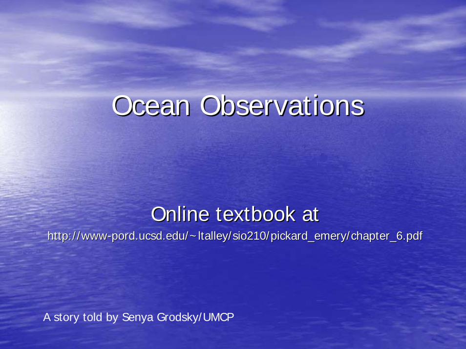
Retrospective story
“From wooden bucket to modern satellite sensors”
Why we care about data taken by obsolete methods?
All data are to be used in order to construct the longest possible records of the ocean climate.
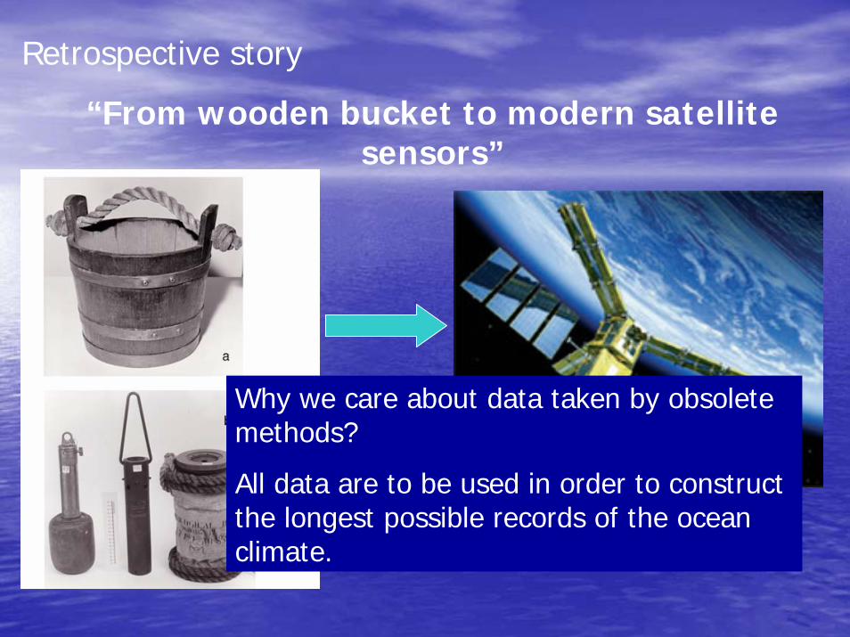
In-situ observations Remote Sensing
High precision
Vertical resolution
All ocean variables
Limited coverage
Retrieve variables from E/M fields
N/A
Only surface variables
Global coverage
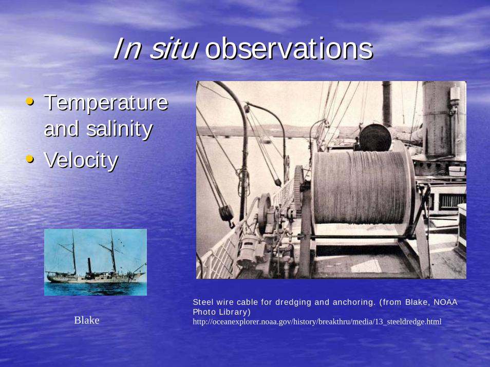
In situIn situ observations observations
•• Temperature Temperature and salinityand salinity
•• VelocityVelocity
Steel wire cable for dredging and anchoring. (from Blake, NOAA Photo Library)http://oceanexplorer.noaa.gov/history/breakthru/media/13_steeldredge.htmlBlake
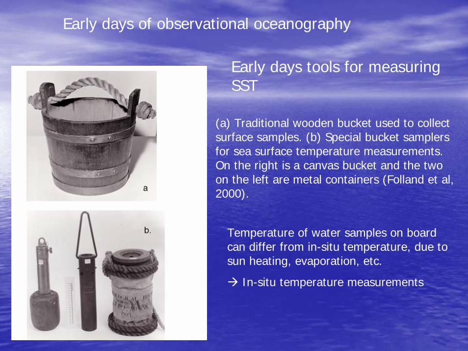
(a) Traditional wooden bucket used to collect surface samples. (b) Special bucket samplers for sea surface temperature measurements. On the right is a canvas bucket and the two on the left are metal containers (Folland et al, 2000).
Early days of observational oceanography
Early days tools for measuring SST
Temperature of water samples on board can differ from in-situ temperature, due to sun heating, evaporation, etc.
In-situ temperature measurements
Early days of in-situ water temperature vertical profiles measurements
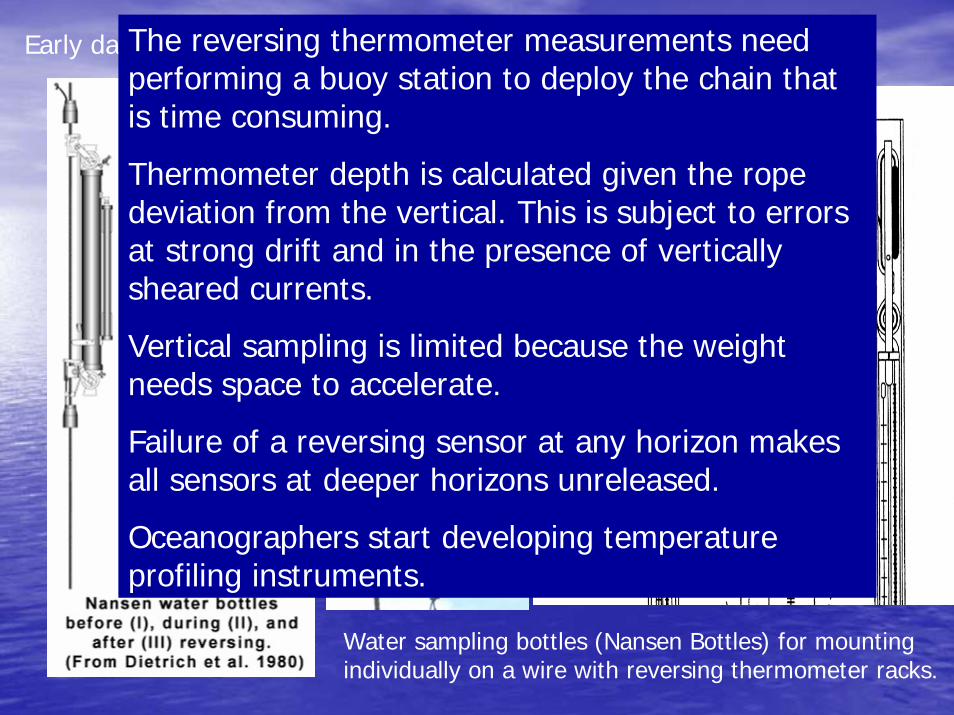
Water sampling bottles (Nansen Bottles) for mounting individually on a wire with reversing thermometer racks.
The reversing thermometer records temperature at depth and then keeps it unchanged (when is turned upside down) while the instrument is brought back to the ship.
The reversing thermometer measurements need performing a buoy station to deploy the chain that is time consuming.
Thermometer depth is calculated given the rope deviation from the vertical. This is subject to errors at strong drift and in the presence of vertically sheared currents.
Vertical sampling is limited because the weight needs space to accelerate.
Failure of a reversing sensor at any horizon makes all sensors at deeper horizons unreleased.
Oceanographers start developing temperature profiling instruments.
Temperature measurementsTemperature measurements•• MBTMBT•• XBTXBT•• CTDCTD•• PALACE floats (evolving into ARGO)PALACE floats (evolving into ARGO)•• Moored buoysMoored buoys
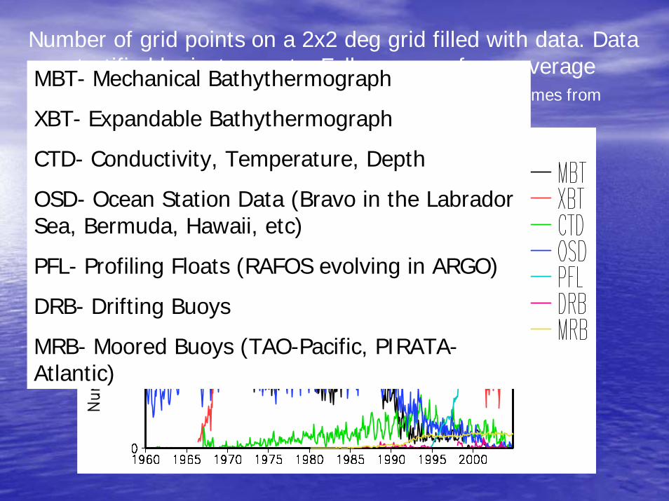
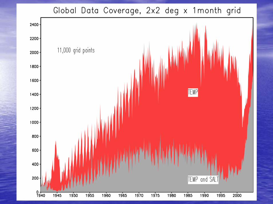
Number of grid points on a 2x2 deg grid filled with data. Data are stratified by instruments. Full ocean surface coverage corresponds to approximately 11,000 points. Data comes from NOAA/NODC Ocean Climate Lab., http://www.nodc.noaa.gov/OC5
MBT- Mechanical Bathythermograph
XBT- Expandable Bathythermograph
CTD- Conductivity, Temperature, Depth
OSD- Ocean Station Data (Bravo in the Labrador Sea, Bermuda, Hawaii, etc)
PFL- Profiling Floats (RAFOS evolving in ARGO)
DRB- Drifting Buoys
MRB- Moored Buoys (TAO-Pacific, PIRATA-Atlantic)
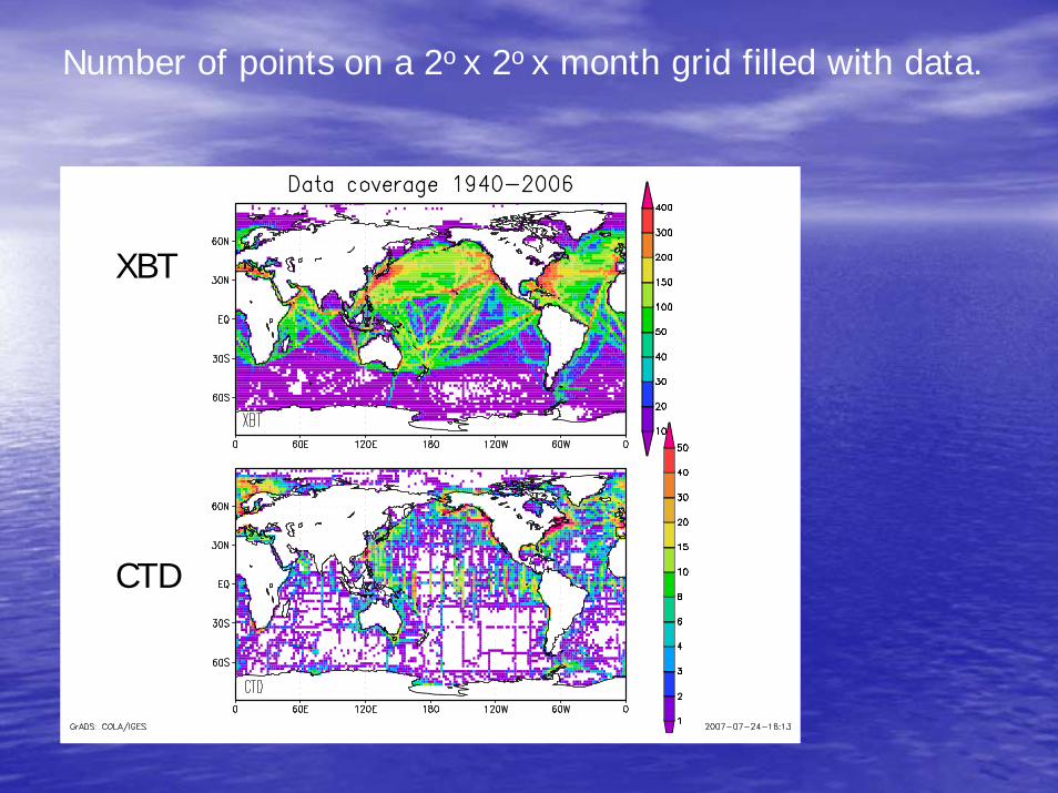
Number of points on a 2o x 2o x month grid filled with data.
XBT
CTD
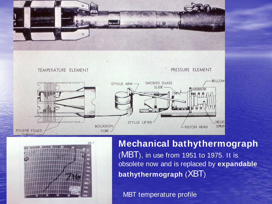
Mechanical bathythermograph(MBT), in use from 1951 to 1975. It is obsolete now and is replaced by expandable bathythermograph (XBT)
MBT temperature profile
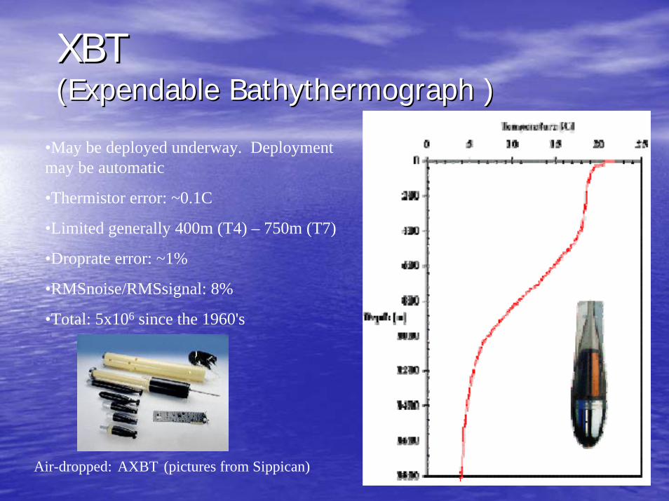
XBTXBT(Expendable Bathythermograph )(Expendable Bathythermograph )
•May be deployed underway. Deployment may be automatic
•Thermistor error: ~0.1C
•Limited generally 400m (T4) – 750m (T7)
•Droprate error: ~1%
•RMSnoise/RMSsignal: 8%
•Total: 5x10⁶ since the 1960's
Air-dropped: AXBT (pictures from Sippican)
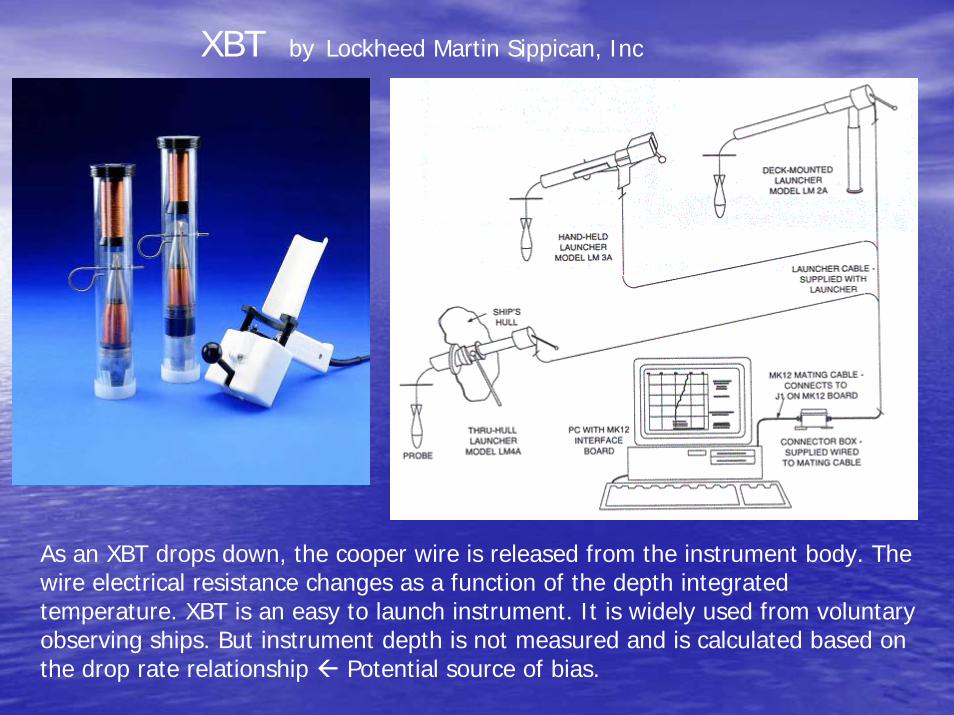
XBT by Lockheed Martin Sippican, Inc
As an XBT drops down, the cooper wire is released from the instrument body. The wire electrical resistance changes as a function of the depth integrated temperature. XBT is an easy to launch instrument. It is widely used from voluntary observing ships. But instrument depth is not measured and is calculated based on the drop rate relationship Potential source of bias.
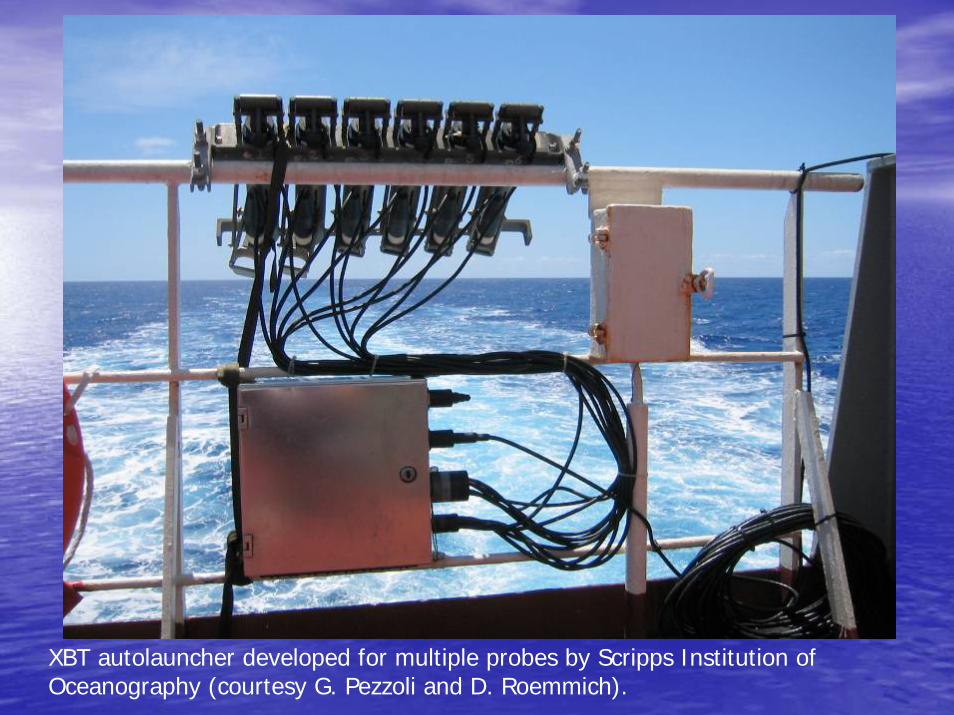
XBT autolauncher developed for multiple probes by Scripps Institution of Oceanography (courtesy G. Pezzoli and D. Roemmich).
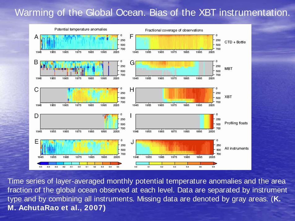
Time series of layer-averaged monthly potential temperature anomalies and the area fraction of the global ocean observed at each level. Data are separated by instrument type and by combining all instruments. Missing data are denoted by gray areas. (K. M. AchutaRao et al., 2007)
Warming of the Global Ocean. Bias of the XBT instrumentation.
Salinity measurement techniques•Titration
•Conductivity (resistivity -1)
Salinity measurements using titration is the classical (Knudsen) method of salinity measurement, in general use prior to about 1960, determined the chlorinity by titration with standard silver nitratesolution (e.g. Strickland and Parsons, 1972).
Modern Salinity measurements methods are based on the dependence of conductivity of the sea water on salinity. In order to obtain salinity measurements from CTDs and similar instruments, temperaturemust be measured simultaneously with conductivity, since conductivity depends primarily on temperature and only secondarily on salinity.
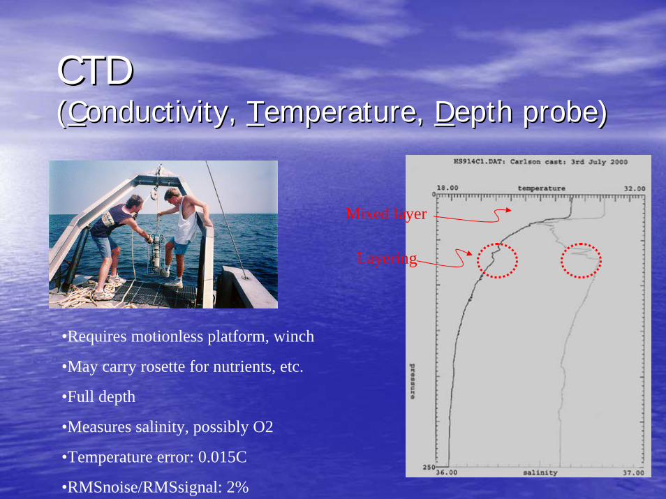
CTDCTD((CConductivity, onductivity, TTemperature, emperature, DDepth probe)epth probe)
•Requires motionless platform, winch
•May carry rosette for nutrients, etc.
•Full depth
•Measures salinity, possibly O2
•Temperature error: 0.015C
•RMSnoise/RMSsignal: 2%
Layering
Mixed layer
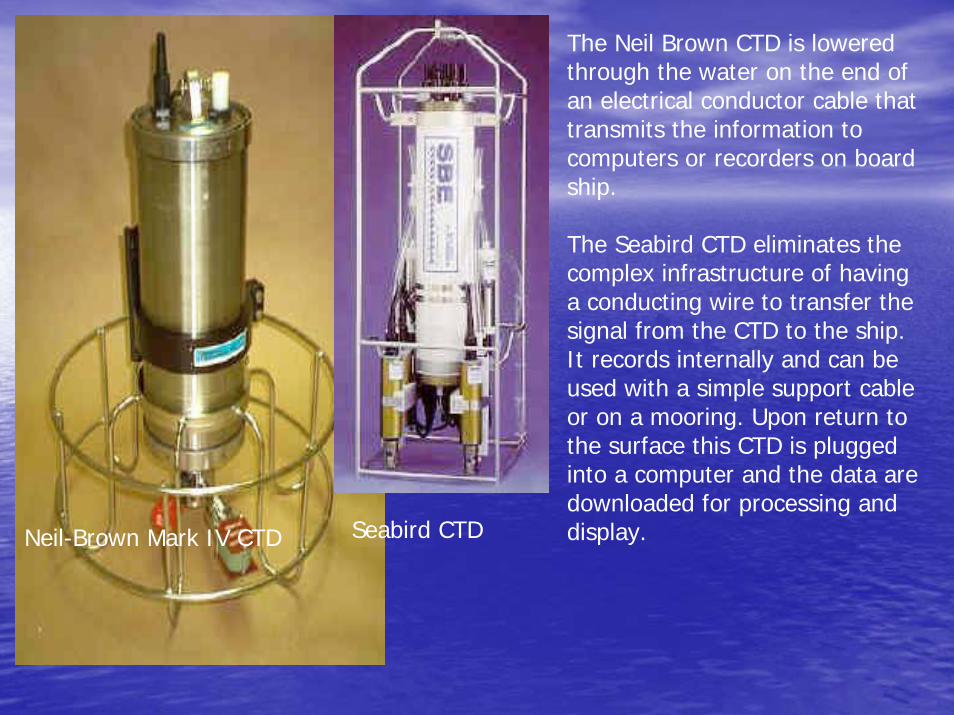
Neil-Brown Mark IV CTD Seabird CTD
The Neil Brown CTD is lowered through the water on the end of an electrical conductor cable that transmits the information to computers or recorders on board ship.
The Seabird CTD eliminates the complex infrastructure of having a conducting wire to transfer thesignal from the CTD to the ship. It records internally and can beused with a simple support cable or on a mooring. Upon return to the surface this CTD is plugged into a computer and the data aredownloaded for processing and display.
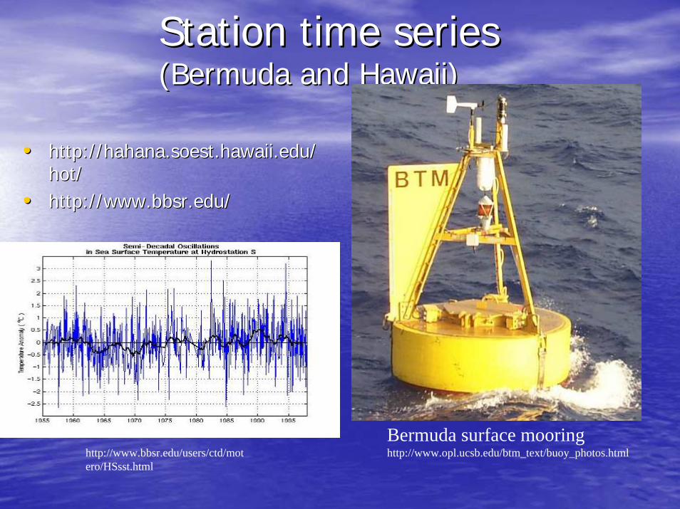
Station time seriesStation time series(Bermuda and Hawaii) (Bermuda and Hawaii)
•• http://hahana.soest.hawaii.edu/http://hahana.soest.hawaii.edu/hot/hot/
•• http://http://www.bbsr.eduwww.bbsr.edu//
Bermuda surface mooringhttp://www.opl.ucsb.edu/btm_text/buoy_photos.htmlhttp://www.bbsr.edu/users/ctd/mot
ero/HSsst.html
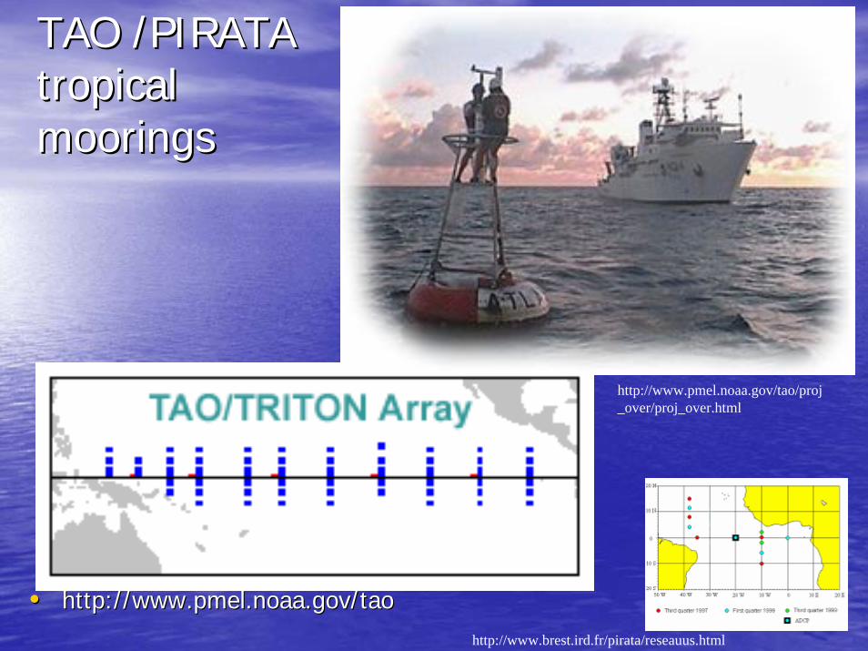
TAO /PIRATA TAO /PIRATA tropical tropical mooringsmoorings
•• http://http://www.pmel.noaa.gov/taowww.pmel.noaa.gov/tao
http://www.pmel.noaa.gov/tao/proj_over/proj_over.html
http://www.brest.ird.fr/pirata/reseauus.html
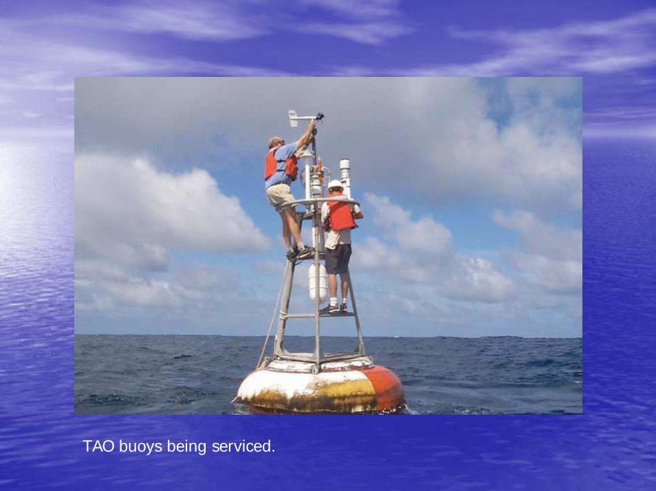
TAO buoys being serviced.
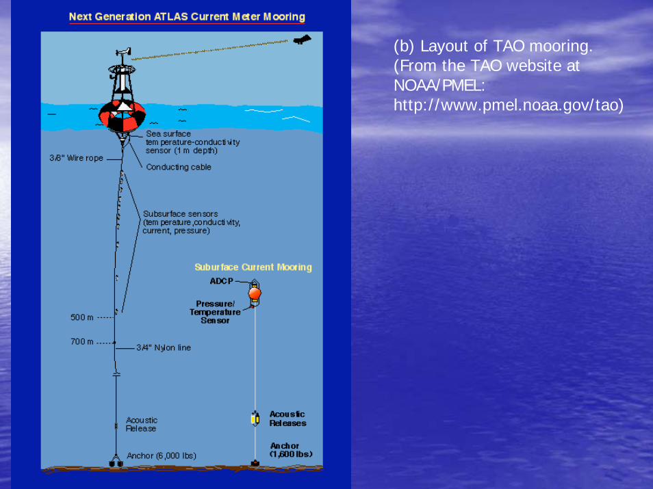
(b) Layout of TAO mooring. (From the TAO website atNOAA/PMEL: http://www.pmel.noaa.gov/tao)
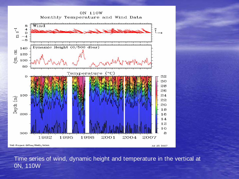
Time series of wind, dynamic height and temperature in the vertical at 0N, 110W
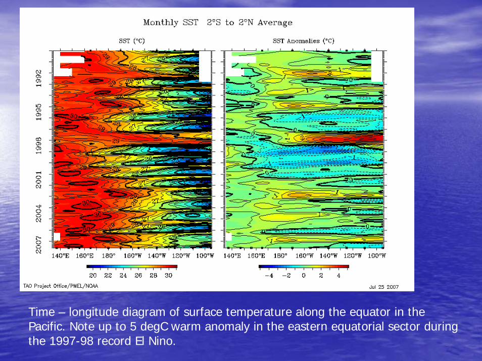
Time – longitude diagram of surface temperature along the equator in the Pacific. Note up to 5 degC warm anomaly in the eastern equatorial sector during the 1997-98 record El Nino.
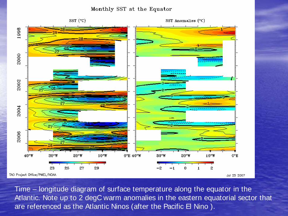
Time – longitude diagram of surface temperature along the equator in the Atlantic. Note up to 2 degC warm anomalies in the eastern equatorial sector that are referenced as the Atlantic Ninos (after the Pacific El Nino ).
Standard ocean measurements are taken on board of research (or voluntary observing) vessels or from ocean moorings.
Ship time is costly. Buoy servicing also requires ship time.
Oceanographers launch development of profiling floats.
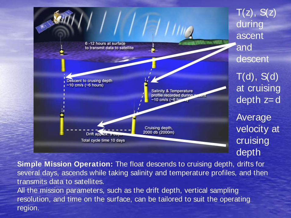
Simple Mission Operation: The float descends to cruising depth, drifts for several days, ascends while taking salinity and temperature profiles, and then transmits data to satellites. All the mission parameters, such as the drift depth, vertical sampling resolution, and time on the surface, can be tailored to suit the operating region.
T(z), S(z) during ascent and descent
T(d), S(d) at cruising depth z=d
Average velocity at cruising depth
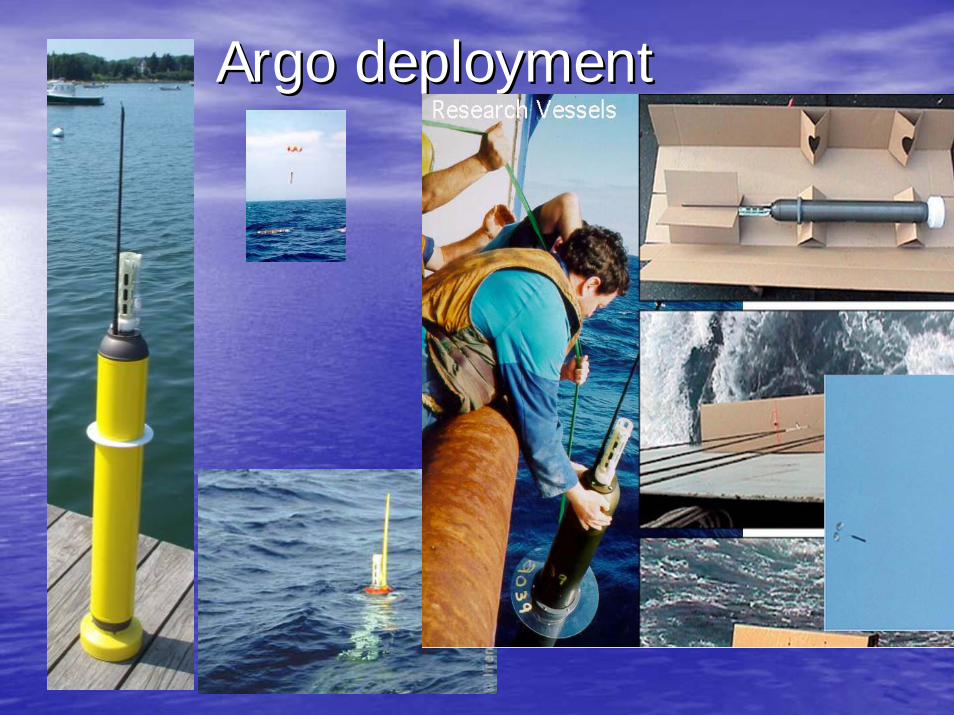
Argo deploymentArgo deployment
An Argo float being deployed from a research ship
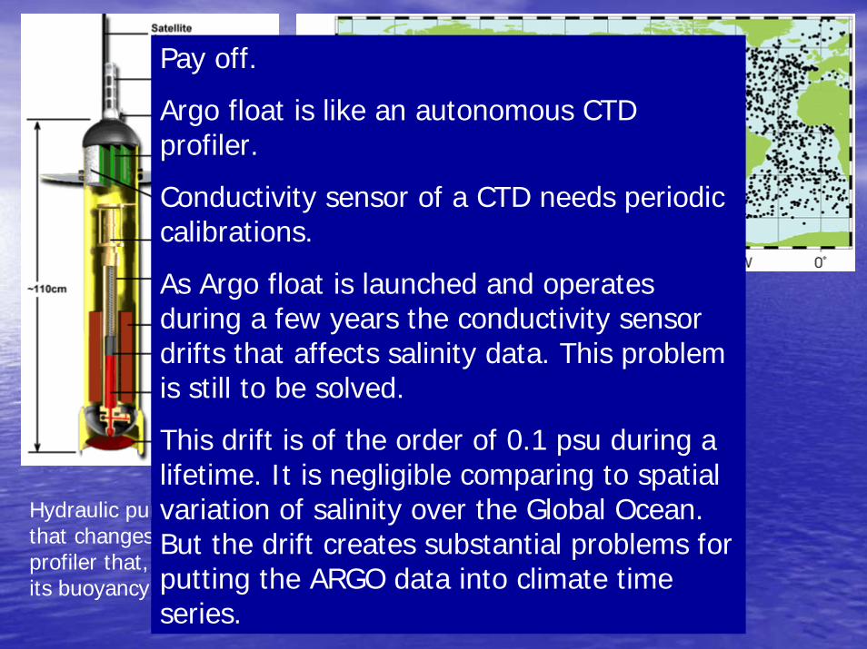
Hydraulic pump shifts bladder that changes the volume of a profiler that, in turn, affects its buoyancy, hence, depth.
Pay off.
Argo float is like an autonomous CTD profiler.
Conductivity sensor of a CTD needs periodic calibrations.
As Argo float is launched and operates during a few years the conductivity sensor drifts that affects salinity data. This problem is still to be solved.
This drift is of the order of 0.1 psu during a lifetime. It is negligible comparing to spatial variation of salinity over the Global Ocean. But the drift creates substantial problems for putting the ARGO data into climate time series.
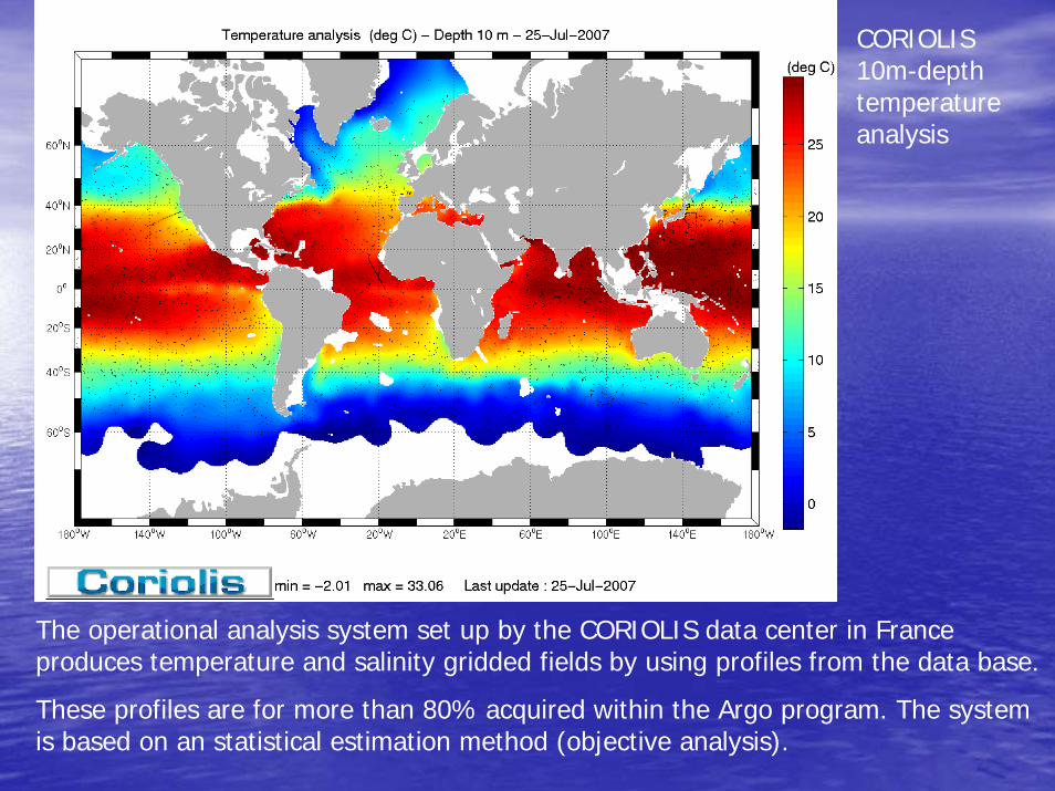
The operational analysis system set up by the CORIOLIS data center in France produces temperature and salinity gridded fields by using profiles from the data base.
These profiles are for more than 80% acquired within the Argo program. The system is based on an statistical estimation method (objective analysis).
CORIOLIS 10m-depth temperature analysis
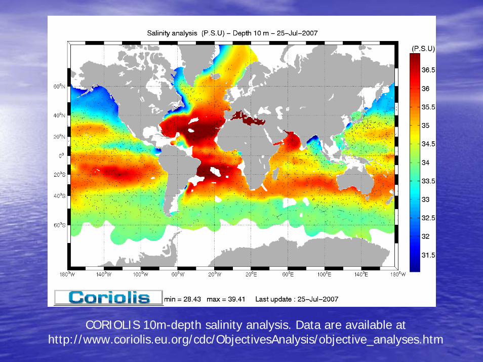
CORIOLIS 10m-depth salinity analysis. Data are available at http://www.coriolis.eu.org/cdc/ObjectivesAnalysis/objective_analyses.htm
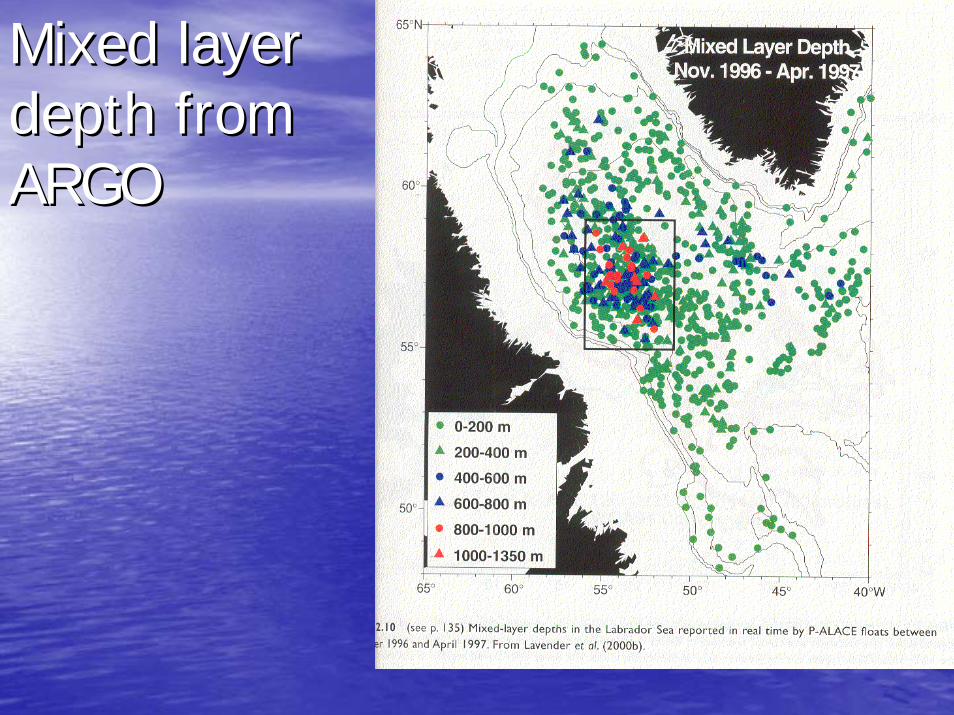
Mixed layer Mixed layer depth from depth from ARGOARGO
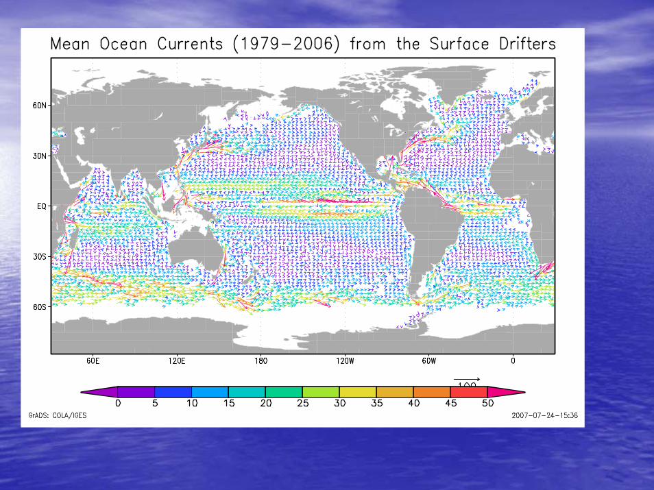
Velocity measurementsVelocity measurements
•• DroguedDrogued surface drifterssurface drifters•• ADCPsADCPs•• PropellerPropeller--type current meterstype current meters•• CODARCODAR
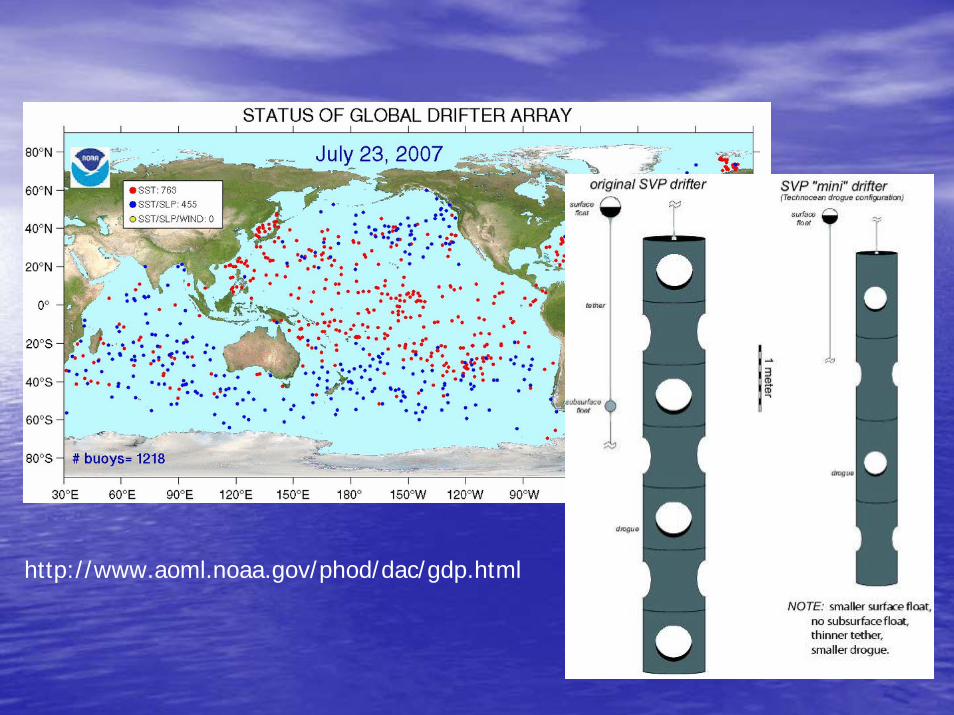
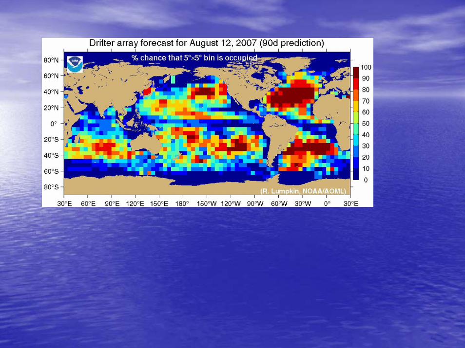
http://www.aoml.noaa.gov/phod/dac/gdp.html
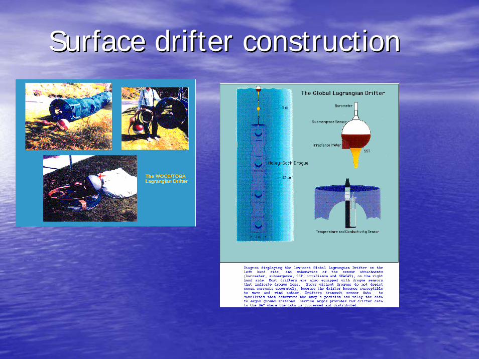
Surface drifter constructionSurface drifter construction
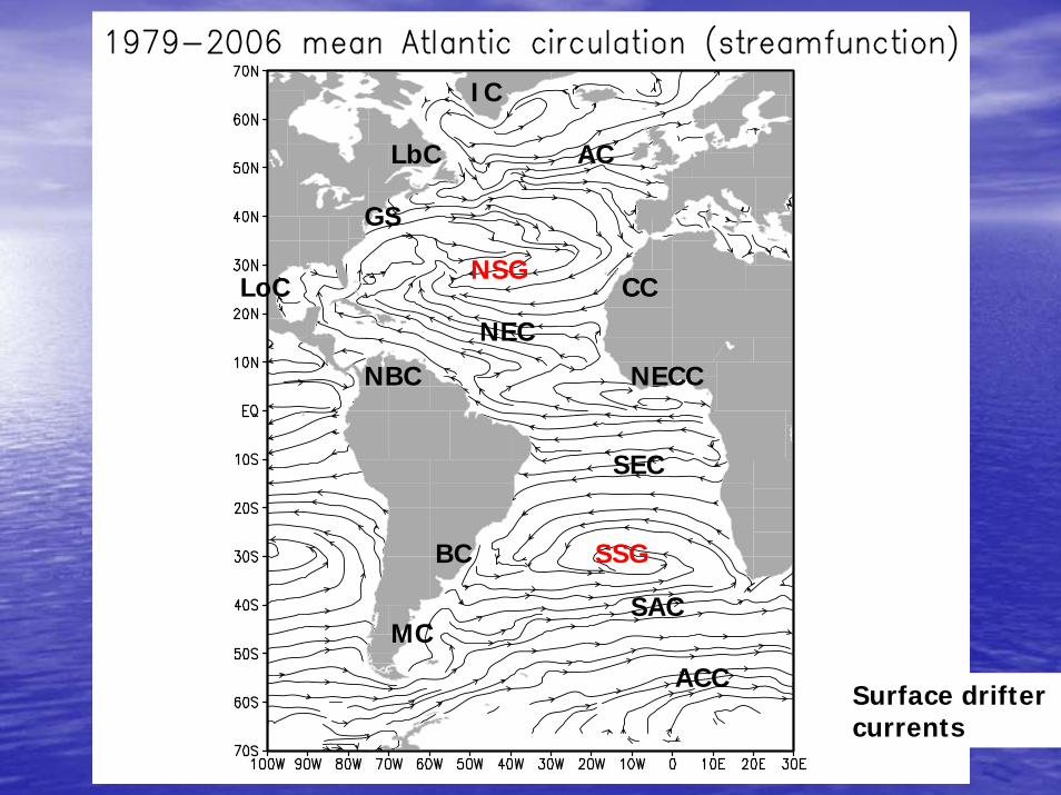
ACC
SAC
SEC
NEC
NECC
GS
AC
IC
NBC
LoC
BC
MC
CCNSG
SSG
LbC
Surface drifter currents
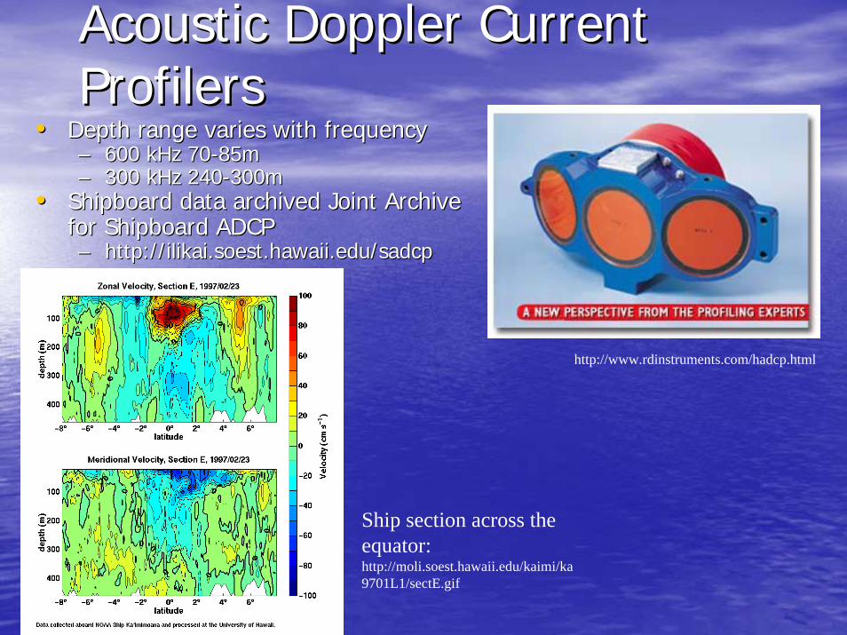
Acoustic Doppler Current Acoustic Doppler Current ProfilersProfilers
•• Depth range varies with frequencyDepth range varies with frequency–– 600 kHz 70600 kHz 70--85m 85m –– 300 kHz 240300 kHz 240--300m 300m
•• Shipboard data archived Joint Archive Shipboard data archived Joint Archive for Shipboard ADCP for Shipboard ADCP –– http://http://ilikai.soest.hawaii.edu/sadcpilikai.soest.hawaii.edu/sadcp
http://www.rdinstruments.com/hadcp.html
Ship section across the equator:http://moli.soest.hawaii.edu/kaimi/ka9701L1/sectE.gif
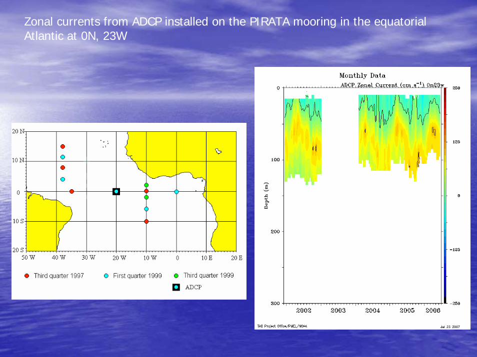
Zonal currents from ADCP installed on the PIRATA mooring in the equatorial Atlantic at 0N, 23W
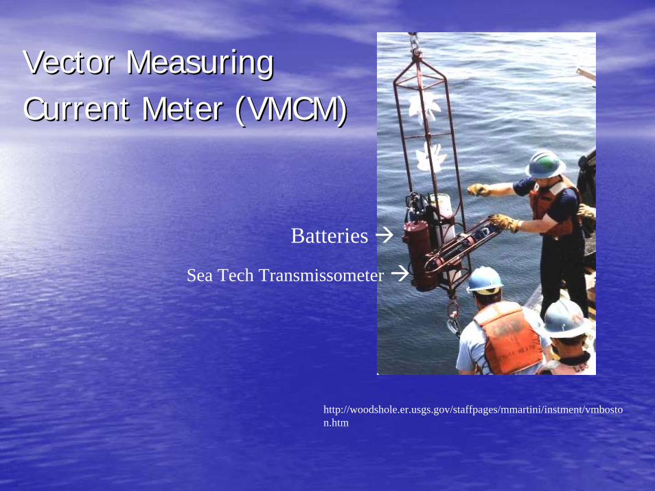
Vector Measuring Vector Measuring Current Meter (VMCM)Current Meter (VMCM)
http://woodshole.er.usgs.gov/staffpages/mmartini/instment/vmboston.htm
Sea Tech Transmissometer
Batteries
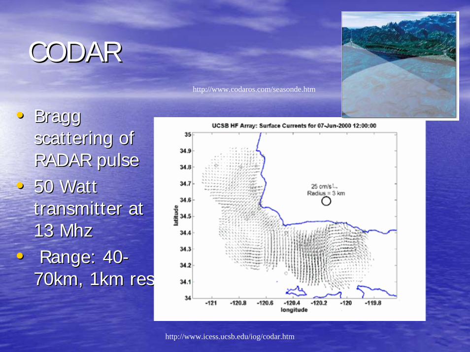
CODARCODAR
•• Bragg Bragg scattering of scattering of RADAR pulseRADAR pulse
•• 50 Watt 50 Watt transmitter at transmitter at 13 13 MhzMhz
•• Range: 40Range: 40--70km, 1km res70km, 1km res
http://www.icess.ucsb.edu/iog/codar.htm
http://www.codaros.com/seasonde.htm
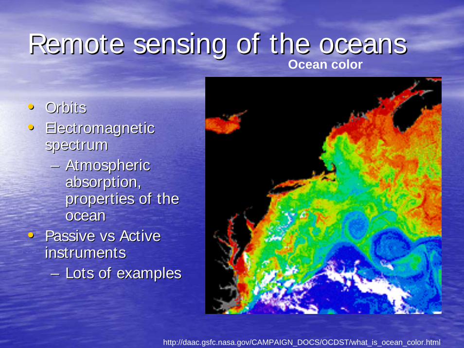
Remote sensing of the oceansRemote sensing of the oceans
•• OrbitsOrbits•• Electromagnetic Electromagnetic
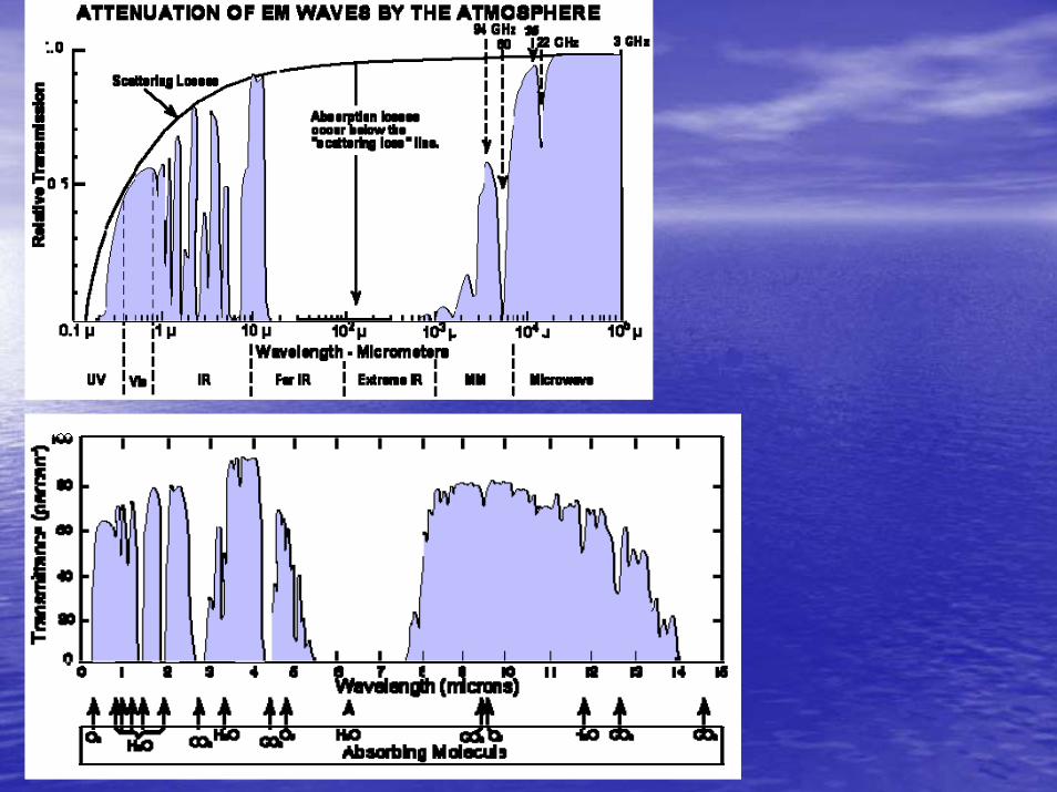
spectrumspectrum–– Atmospheric Atmospheric
absorption, absorption, properties of the properties of the oceanocean
•• Passive Passive vsvs Active Active instrumentsinstruments–– Lots of examplesLots of examples
http://daac.gsfc.nasa.gov/CAMPAIGN_DOCS/OCDST/what_is_ocean_color.html
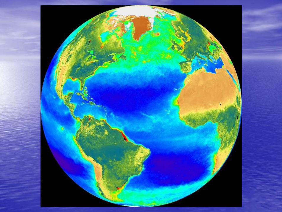
Ocean color
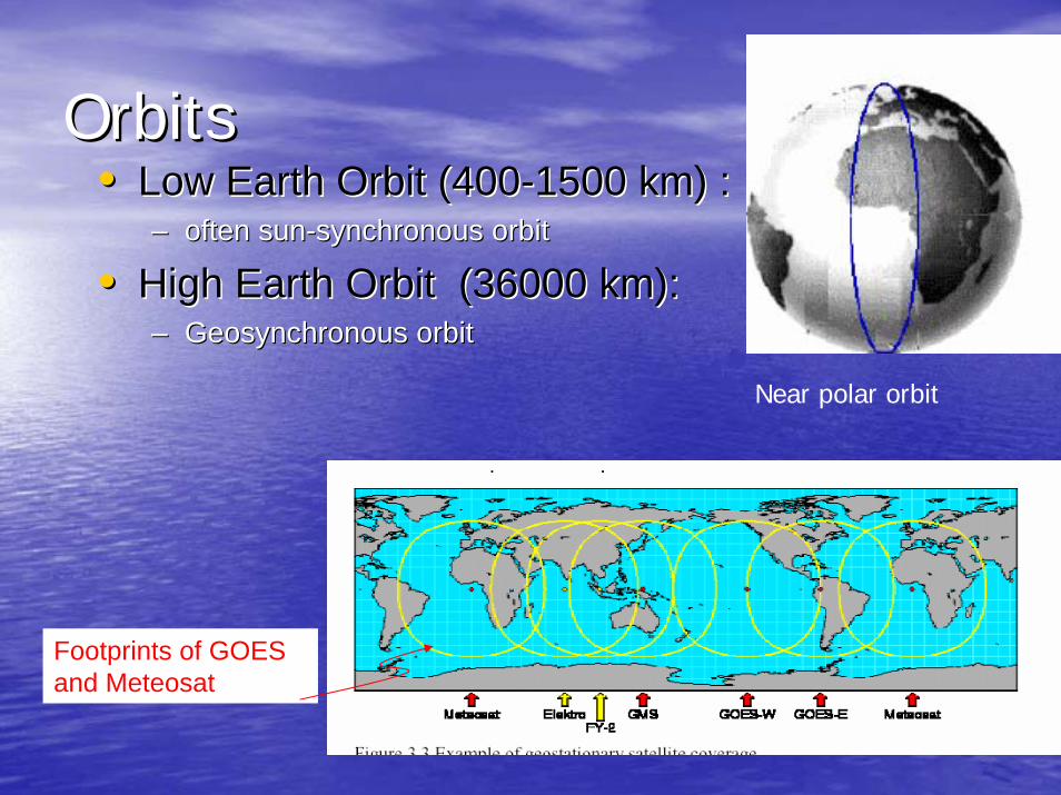
OrbitsOrbits
Footprints of GOES and Meteosat
•• Low Earth Orbit (400Low Earth Orbit (400--1500 km) :1500 km) :–– often sunoften sun--synchronous orbitsynchronous orbit
•• High Earth Orbit (36000 km)High Earth Orbit (36000 km): : –– Geosynchronous orbitGeosynchronous orbit
Near polar orbit
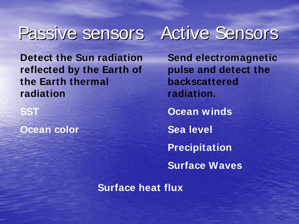
Passive sensors Active SensorsPassive sensors Active SensorsDetect the Sun radiation reflected by the Earth of the Earth thermal radiation
SST
Ocean color
Send electromagnetic pulse and detect the backscattered radiation.
Ocean winds
Sea level
Precipitation
Surface Waves
Surface heat flux
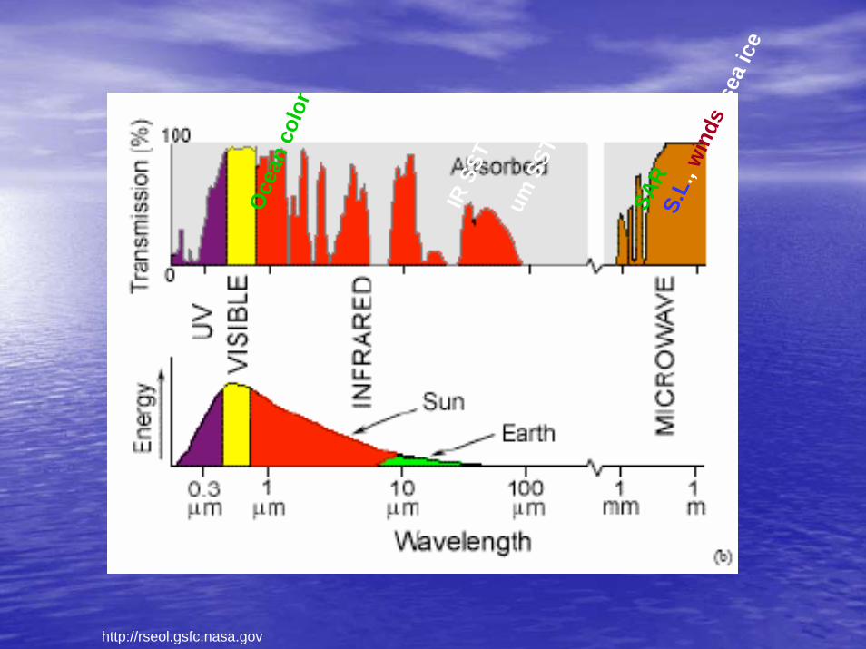
http://rseol.gsfc.nasa.gov
Oce
an c
olor
IR S
STum
SST
S.L.
, win
ds, s
ea ic
e
SAR
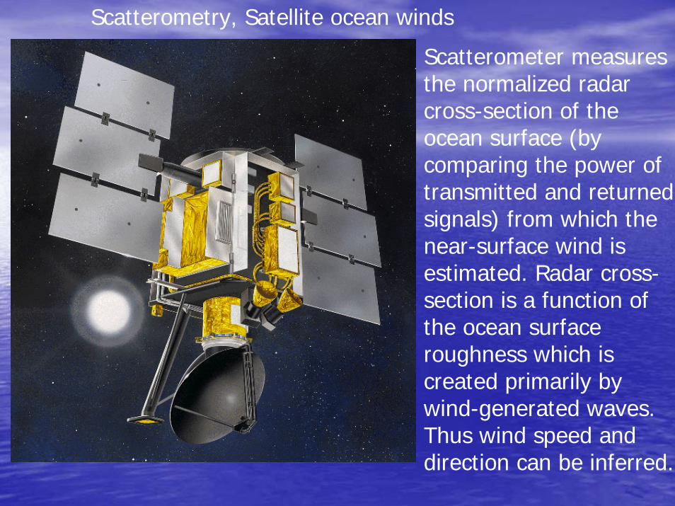
Scatterometer measures the normalized radar cross-section of the ocean surface (by comparing the power of transmitted and returned signals) from which the near-surface wind is estimated. Radar cross-section is a function of the ocean surface roughness which is created primarily by wind-generated waves. Thus wind speed and direction can be inferred.
Scatterometry, Satellite ocean winds
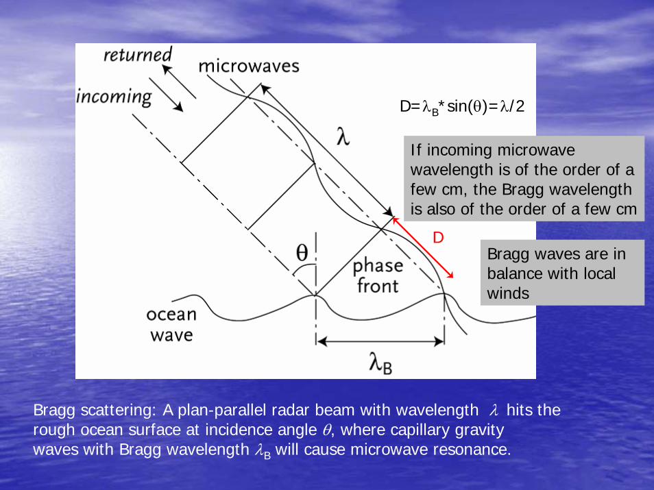
Bragg scattering: A plan-parallel radar beam with wavelength λ hits the rough ocean surface at incidence angle θ, where capillary gravitywaves with Bragg wavelength λB will cause microwave resonance.
D
D=λB*sin(θ)=λ/2
If incoming microwave wavelength is of the order of a few cm, the Bragg wavelength is also of the order of a few cm
Bragg waves are in balance with local winds
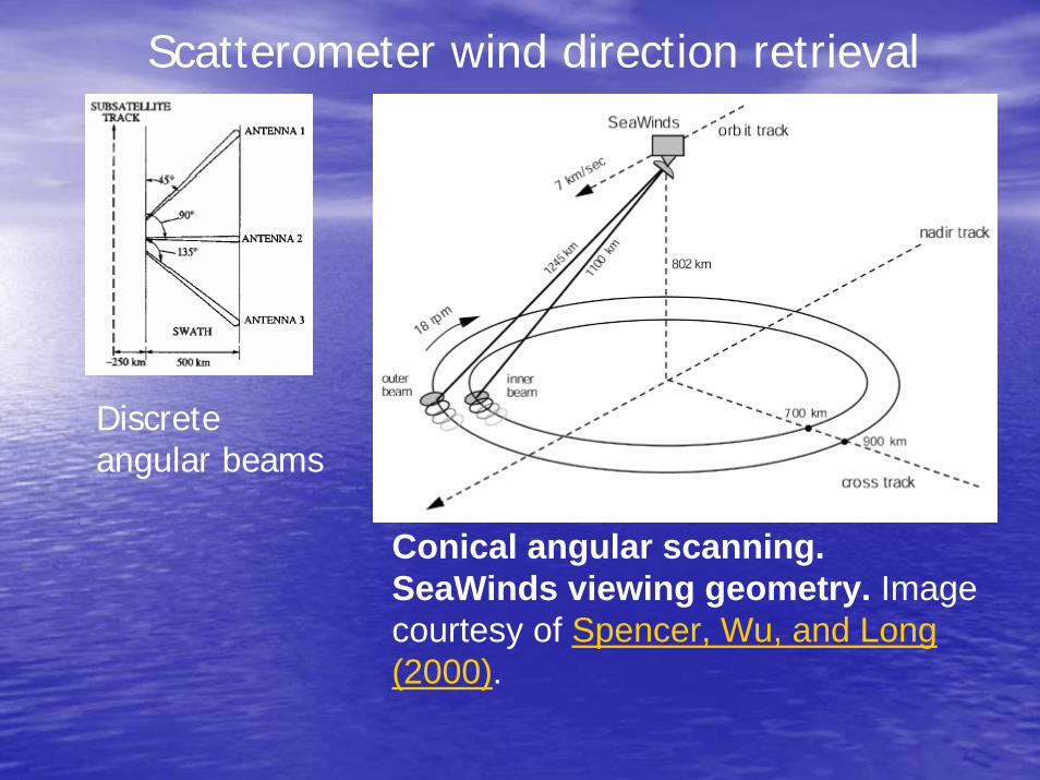
Conical angular scanning.SeaWinds viewing geometry. Image courtesy of Spencer, Wu, and Long (2000).
Discrete angular beams
Scatterometer wind direction retrieval
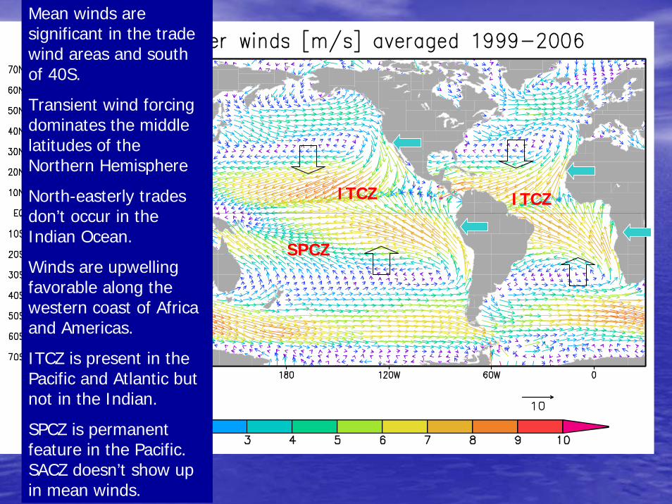
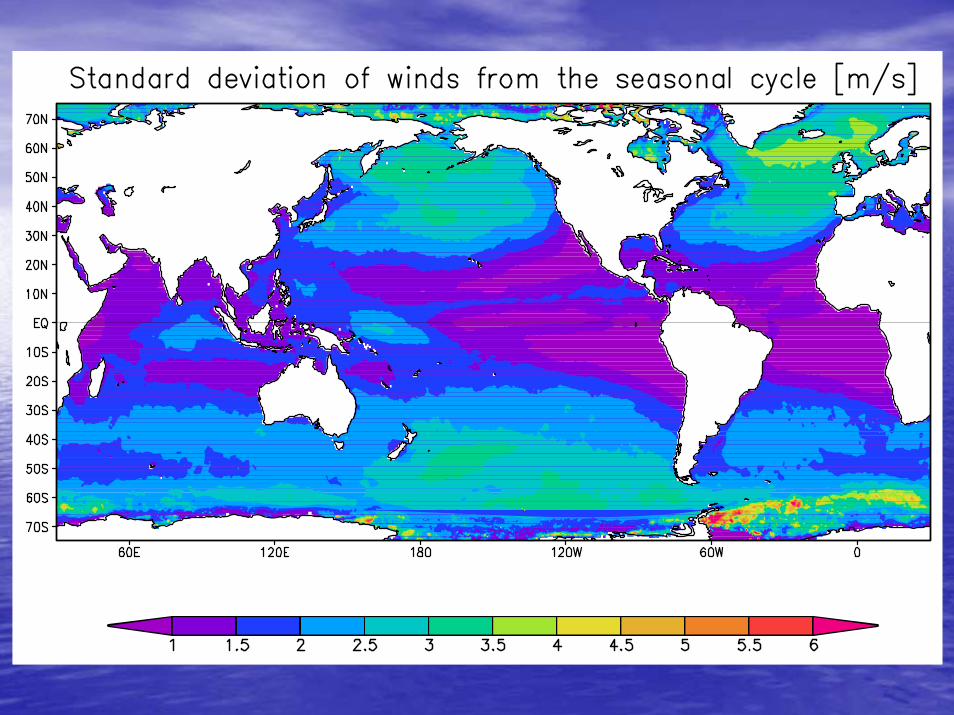
Mean winds are significant in the trade wind areas and south of 40S.
Transient wind forcing dominates the middle latitudes of the Northern Hemisphere
North-easterly trades don’t occur in the Indian Ocean.
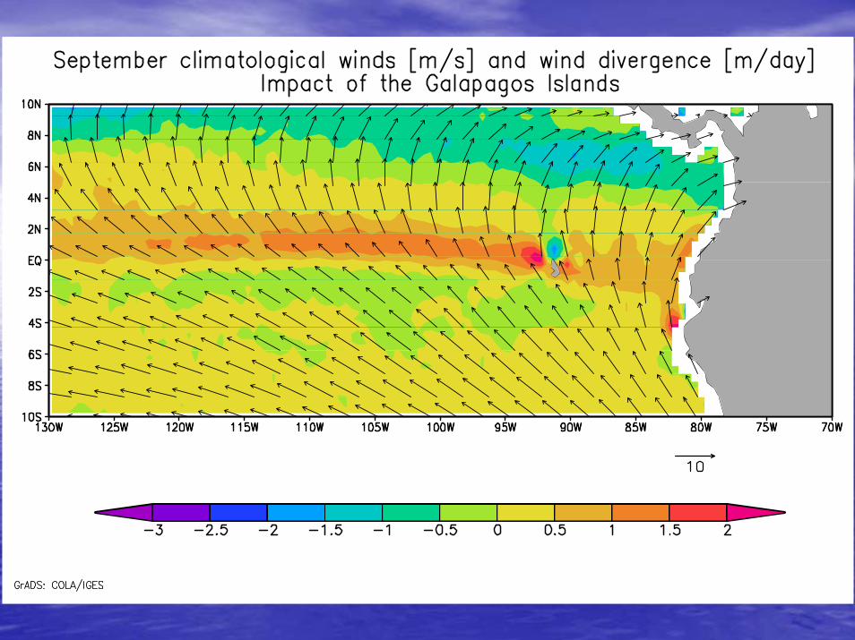
Winds are upwelling favorable along the western coast of Africa and Americas.
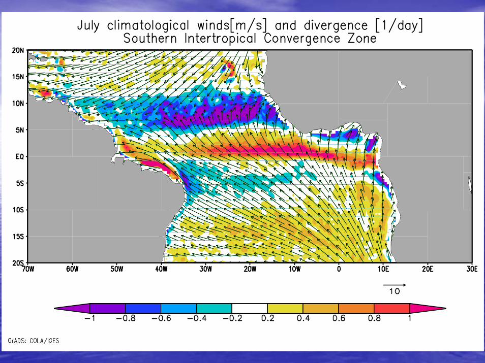
ITCZ is present in the Pacific and Atlantic but not in the Indian.
SPCZ is permanent feature in the Pacific. SACZ doesn’t show up in mean winds.
ITCZ ITCZ
SPCZ
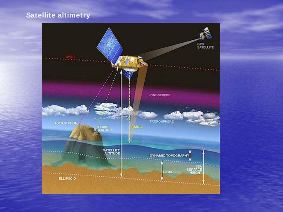
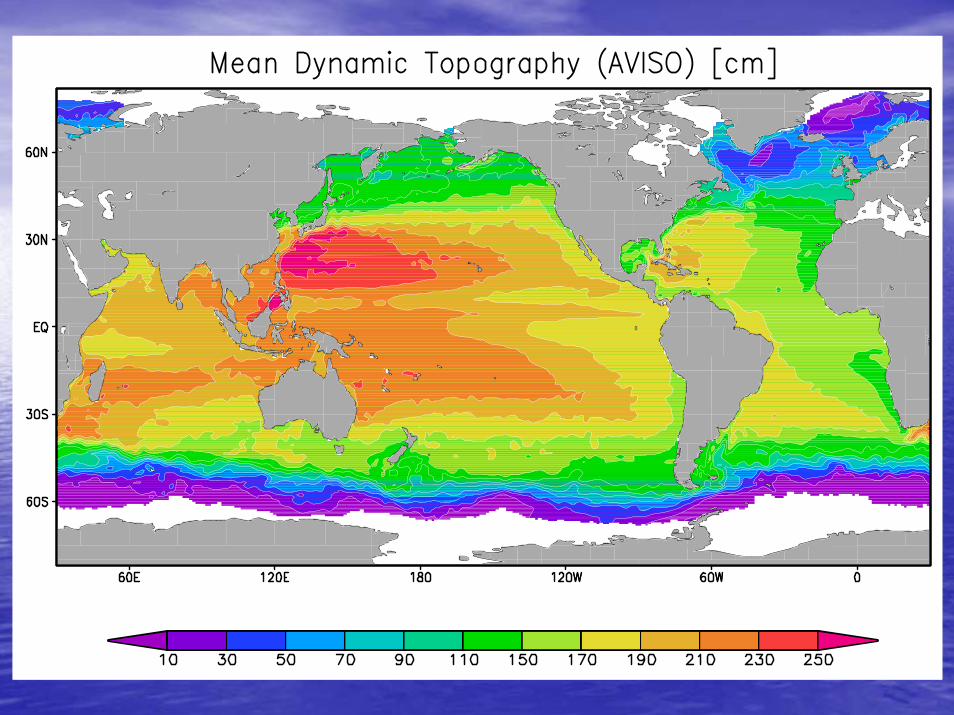
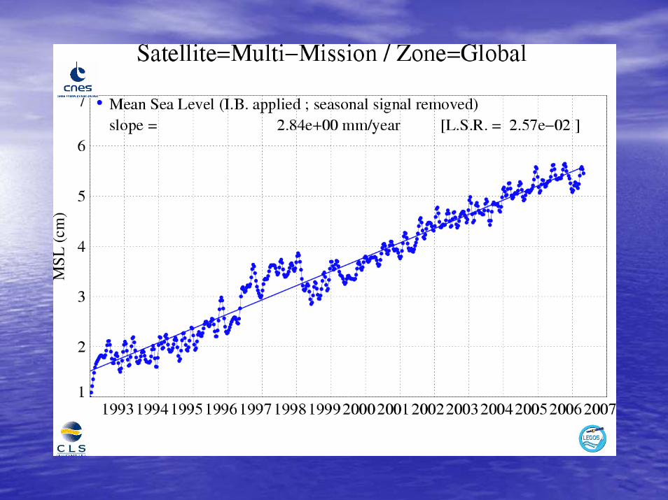
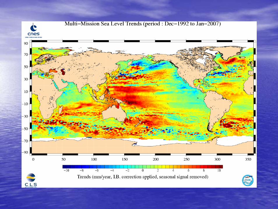
Satellite altimetry

http://www.aviso.oceanobs.com
Satellite altimetry allows to measure the Sea Surface Height (SSH) with a few centimeters precision.
Unfortunately, the satellite orbit is referenced to the earth ellipsoid, and the sea surface elevation measured is also reference to the ellipsoid. This elevation contains the marine geoid plus the sea elevation due to the oceanic circulation (ie the dynamic topography).
The marine geoid is poorly known (precision of a meter...) but is stationary (not changing over the time). In that way, what we do is to remove the Mean Sea Height (after several altimetric measurements over the same point of the ocean, a mean temporal value can be calculated, and this mean sea height would contains the marine geoid plus the permanent height of the dynamic topography). Then we obtain Sea Level Anomalies.
So we can study the VARIABLE PART of the ocean circulation!
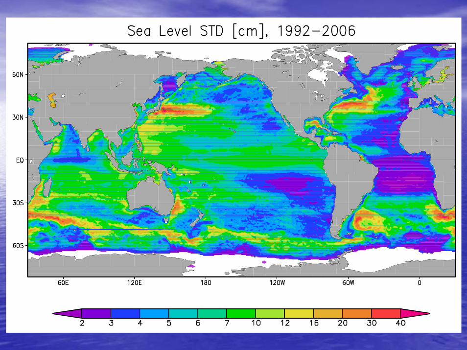
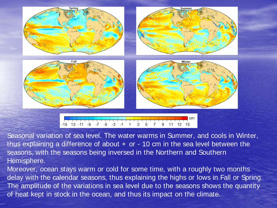
Seasonal variation of sea level. The water warms in Summer, and cools in Winter, thus explaining a difference of about + or - 10 cm in the sea level between the seasons, with the seasons being inversed in the Northern and Southern Hemisphere. Moreover, ocean stays warm or cold for some time, with a roughly two months delay with the calendar seasons, thus explaining the highs or lows in Fall or Spring. The amplitude of the variations in sea level due to the seasons shows the quantity of heat kept in stock in the ocean, and thus its impact on the climate.
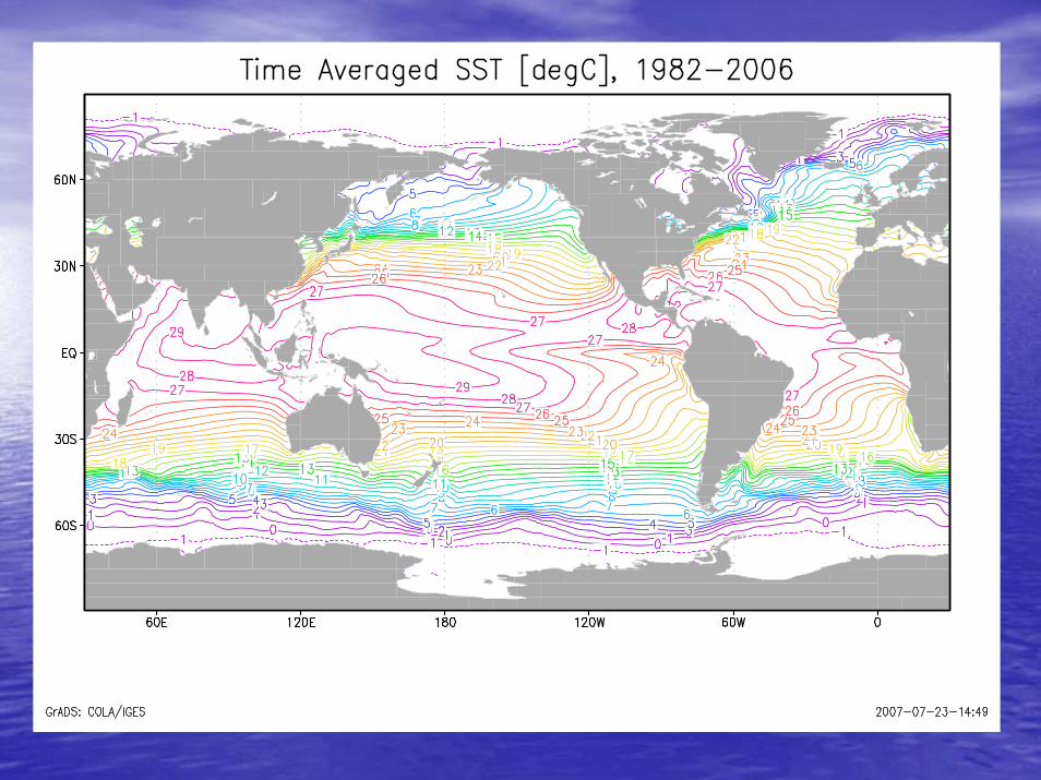
•• Objectively analyzed AVHRR (Infra Red) plus Objectively analyzed AVHRR (Infra Red) plus in situ in situ SST (SST (Reynolds and SmithReynolds and Smith), 1982), 1982--presentpresent
http://http://www.emc.ncep.noaa.gov/research/cmbwww.emc.ncep.noaa.gov/research/cmb/sst_analysis/sst_analysis//
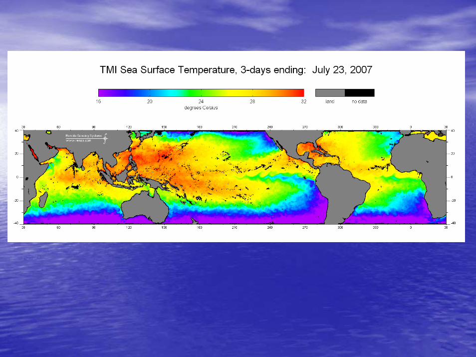
•• Microwave SST from the Tropical Rainfall measuring Microwave SST from the Tropical Rainfall measuring Mission Temperature Microwave Imager (TMI), Mission Temperature Microwave Imager (TMI), 19981998--presentpresent
http://http://www.ssmi.comwww.ssmi.com
Satellite SST datasets
SSTSST
•• Infrared (near 3.7 Infrared (near 3.7 µµm for night, near 10 m for night, near 10 µµm for day)m for day)–– Advanced Very High Resolution Radiometer (Advanced Very High Resolution Radiometer (AVHRRAVHRR) ) –– AlongAlong--Track Scanning Radiometer (Track Scanning Radiometer (ATSRATSR [ERS series]) [ERS series]) –– Geostationary Operational Environmental Satellite (Geostationary Operational Environmental Satellite (GOESGOES) )
ImagerImager–– Moderate Resolution Imaging Moderate Resolution Imaging SpectroSpectro--radiometer radiometer
((MODISMODIS) ) •• Microwave (7Microwave (7--10 GHz)10 GHz)
–– Scanning Scanning MultichannelMultichannel Microwave Radiometer (Microwave Radiometer (SMMRSMMR) ) –– TRMMTRMM Microwave Imager (Microwave Imager (TMITMI) ) –– Advanced Microwave Scanning Radiometer (Advanced Microwave Scanning Radiometer (AMSRAMSR))
John Maurer, UC Boulder http://cires.colorado.edu/~maurerj/class/SST_presentation.htm
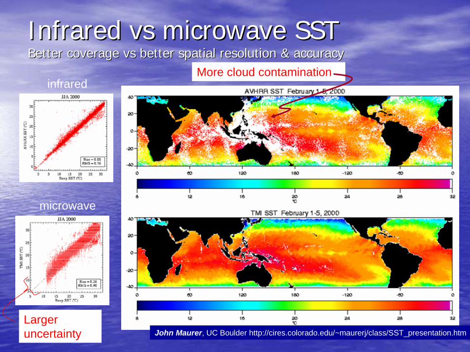
Infrared Infrared vsvs microwave SSTmicrowave SSTBetter coverage Better coverage vsvs better spatial resolution & accuracybetter spatial resolution & accuracy
John Maurer, UC Boulder http://cires.colorado.edu/~maurerj/class/SST_presentation.htm
infrared
microwave
More cloud contamination
Larger uncertainty
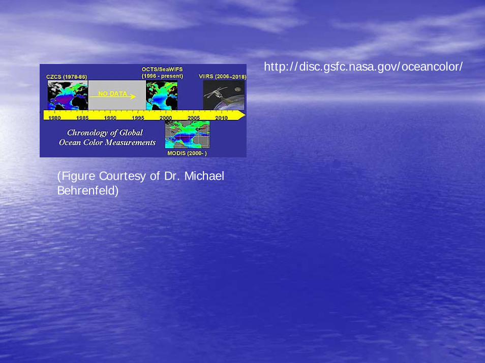
(Figure Courtesy of Dr. Michael Behrenfeld)
http://disc.gsfc.nasa.gov/oceancolor/
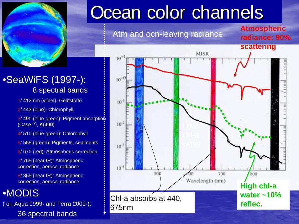
Low chl-a water
Atm and ocn-leaving radianceAtmospheric radiance: 90% scattering
High chl-a water ~10% reflec.
Chl-a absorbs at 440, 675nm
•SeaWiFS (1997-):8 spectral bands
1/ 412 nm (violet): Gelbstoffe
2/ 443 (blue): Chlorophyll
3/ 490 (blue-green): Pigment absorption (Case 2), K(490)
4/ 510 (blue-green): Chlorophyll
5/ 555 (green): Pigments, sediments
6/ 670 (red): Atmospheric correction
7/ 765 (near IR): Atmospheric correction, aerosol radiance
8/ 865 (near IR): Atmospheric correction, aerosol radiance
•MODIS ( on Aqua 1999- and Terra 2001-):
36 spectral bands
Ocean color channelsOcean color channels
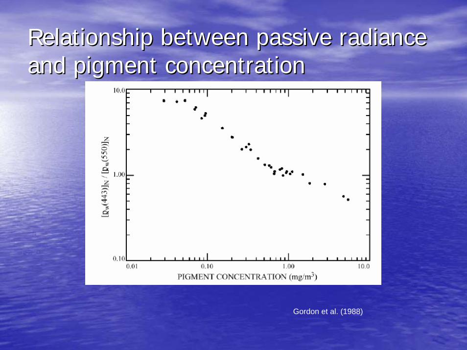
Relationship between passive radiance Relationship between passive radiance and pigment concentrationand pigment concentration
Gordon et al. (1988)
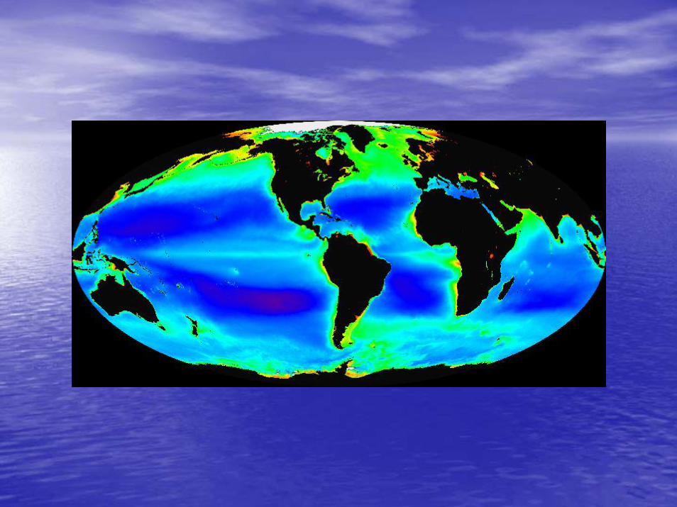
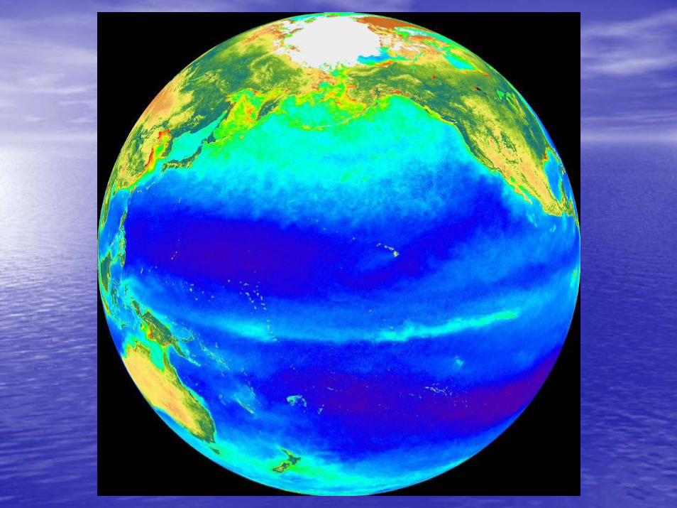
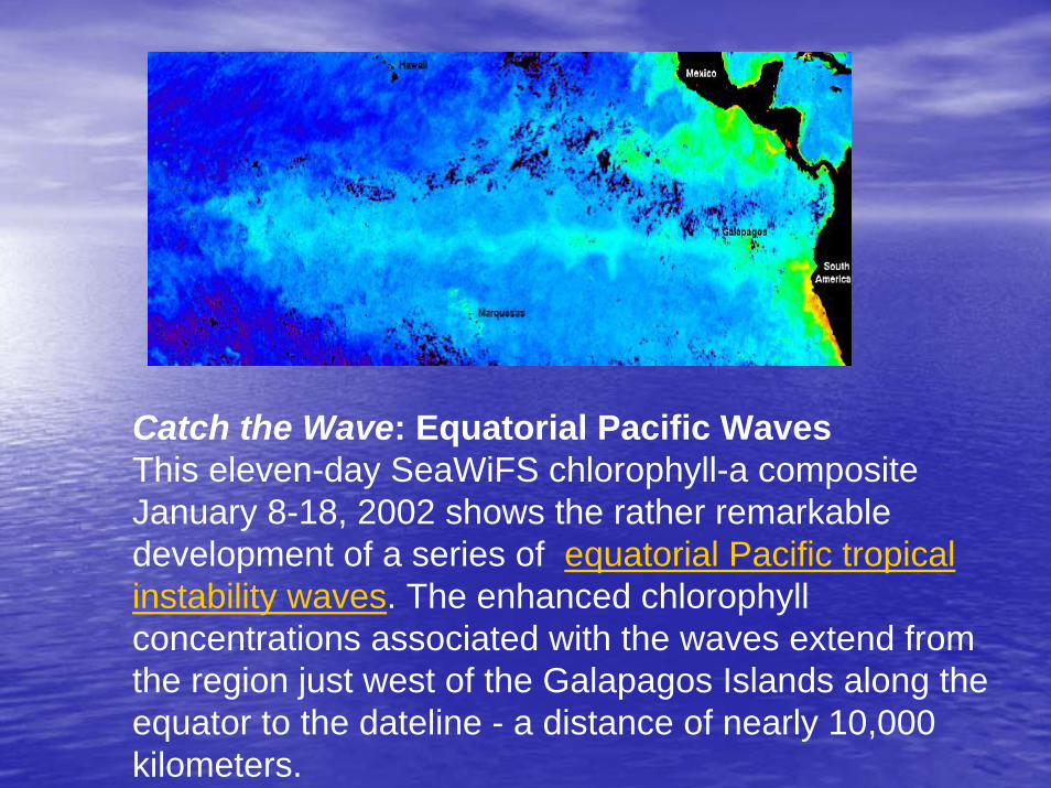
Catch the Wave: Equatorial Pacific WavesThis eleven-day SeaWiFS chlorophyll-a composite January 8-18, 2002 shows the rather remarkable development of a series of equatorial Pacific tropical instability waves. The enhanced chlorophyll concentrations associated with the waves extend from the region just west of the Galapagos Islands along the equator to the dateline - a distance of nearly 10,000 kilometers.
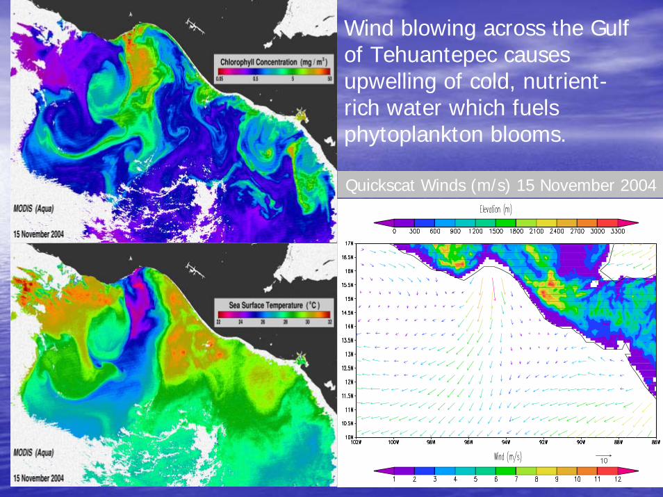
Wind blowing across the Gulf of Tehuantepec causes upwelling of cold, nutrient-rich water which fuels phytoplankton blooms.
Quickscat Winds (m/s) 15 November 2004
Where we hope to see the biggest advances Where we hope to see the biggest advances in the ocean observing system?in the ocean observing system?
Remote sensingRemote sensing
Ocean salinity from space (AQUARIUS Ocean salinity from space (AQUARIUS mission)mission)
InIn--situsitu
Progress of the ARGO float ProgramProgress of the ARGO float Program