Embed Size (px)
Citation preview
@DUKEENERGY, Scott L. BatsonVice President
Oconee Nuclear Station
Duke EnergyONOIVP 17800 Rochester Hw"
Seneca, SC 29672
o: 864.873.3274f. 864.873. 4208
April 24, 2014
U. S. Nuclear Regulatory CommissionDocument Control DeskWashington, D. C. 20555-0001
Subject: Duke Energy Carolinas, LLCOconee Nuclear Site Docket Number 50-287Core Operating Limits Report (COLR)
Attached, pursuant to Oconee Technical Specification 5.6.5.d, is an information copy of theCore Operating Limits Report for Oconee Unit 3, Cycle 27, ONEI-0400-70, Revision 35.
If you have any questions, please direct them to Judy Smith at 864-873-4309.
Sincerely,
Scott L. BatsonVice PresidentOconee Nuclear Station
Attachment
ADD
www.duke-energy.com
U.S. Nuclear Regulatory CommissionApril 24, 2014Page 2
xc w/att: Mr. Victor McCree, Regional AdministratorU.S. Nuclear Regulatory Commission, Region IIMarquis One Tower245 Peachtree Center Ave., NE, Suite 1200Atlanta, GA 30303-1257
Mr. James R. Hall(By electronic mail only)U.S. Nuclear Regulatory CommissionOne White Flint North, M/S O-8B111555 Rockville PikeRockville, MD 20852-2746
Mr. Eddy CroweSenior Resident InspectorOconee Nuclear Site
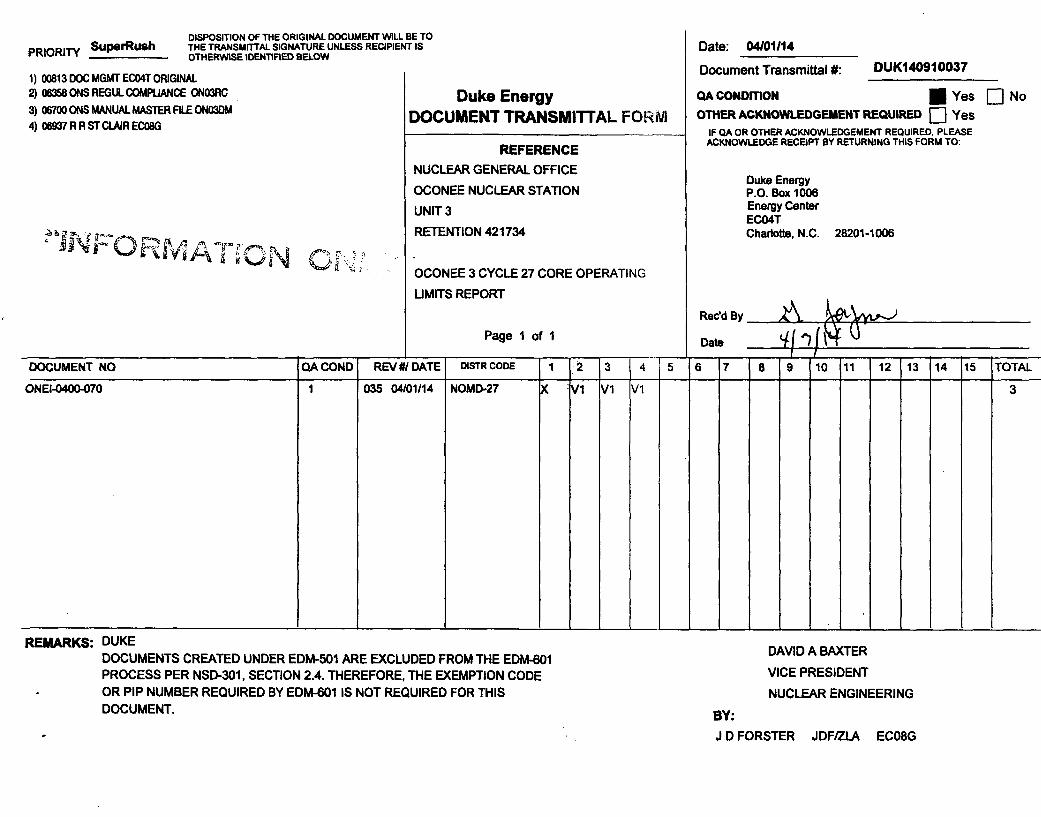
PRIORITY SuperRushDISPOSITION OF THE ORIGINAL DOCUMENT WILL BE TOTHE TRANSMITTAL SIGNATURE UNLESS RECIPIENT ISOTHERWISE IDENTIFIED BELOW
1) 00813 DOC MGMT EC04T ORIGINAL2) 06358 ONS REGUL COMPLIANCE ON03RC
3) 06700 ONS MANUAL MASTER FILE ON03DM4) 06937 R R ST CLAIR EC08G
4 b
1i ,BW ~j
Duke EnergyDOCUMENT TRANSMITTAL FORM
REFERENCE
NUCLEAR GENERAL OFFICE
OCONEE NUCLEAR STATION
UNIT 3
RETENTION 421734
OCONEE 3 CYCLE 27 CORE OPERATING
UMITS REPORT
Date: 04/01114
Document Transmittal #: DUK140910037
QA CONDmON I Yes [:] No
OTHER ACKNOWLEDGEMENT REQUIRED [] YesIF QA OR OTHER ACKNOWLEDGEMENT REQUIRED, PLEASE
ACKNOWLEDGE RECEIPT BY RETURNING THIS FORM TO:
Duke EnergyP.O. Box 1006Energy CenterEC04TCharlotte, N.C. 28201-1006
A &-,NRedd By
Page 1 of 1 Date
DOCUMENT NO QA COND REV #/ DATE DISTR CODE 1 1-2 3 4 5 6 7 8 9 (10 1i1 12 13 14 15 TOTAL-4 4
ONEI-0400-070 1 035 04/01/14 NOMD-27 vi vi vi 3
. . . . . . . . . . . .REMARKS: DUKE
DOCUMENTS CREATED UNDER EDM-501 ARE EXCLUDED FROM THE EDM-601PROCESS PER NSD-301, SECTION 2.4. THEREFORE, THE EXEMPTION CODEOR PIP NUMBER REQUIRED BY EDM-601 IS NOT REQUIRED FOR THISDOCUMENT.
DAVID A BAXTER
VICE PRESIDENT
NUCLEAR ENGINEERING
BY:
J D FORSTER JDF/ZLA EC08G
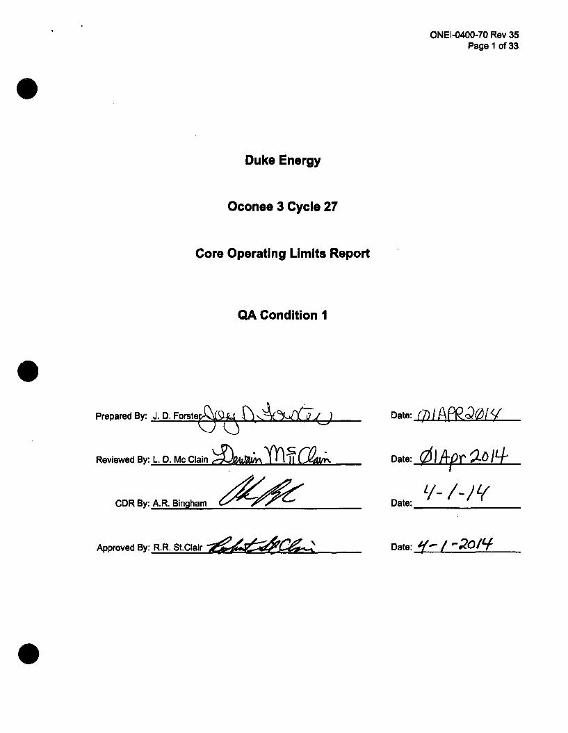
ONEI-0400-70 Rev 35Page 1 of 33
Duke Energy
Oconee 3 Cycle 27
Core Operating Limits Report
QA Condition 1
Prepared By: J. D. Forste Qp. %ykLS ~< Date: I A Q
Date: 1 o#r a• /4Reviewed By: L. D. Mc Clain Z-ftx•n ThqClLA9..... i I
CDRBy:A.R. Blngham
Approved By: R.R. St.Clair
I/- I- I LýDate:
Date: '"-! / .2oA/
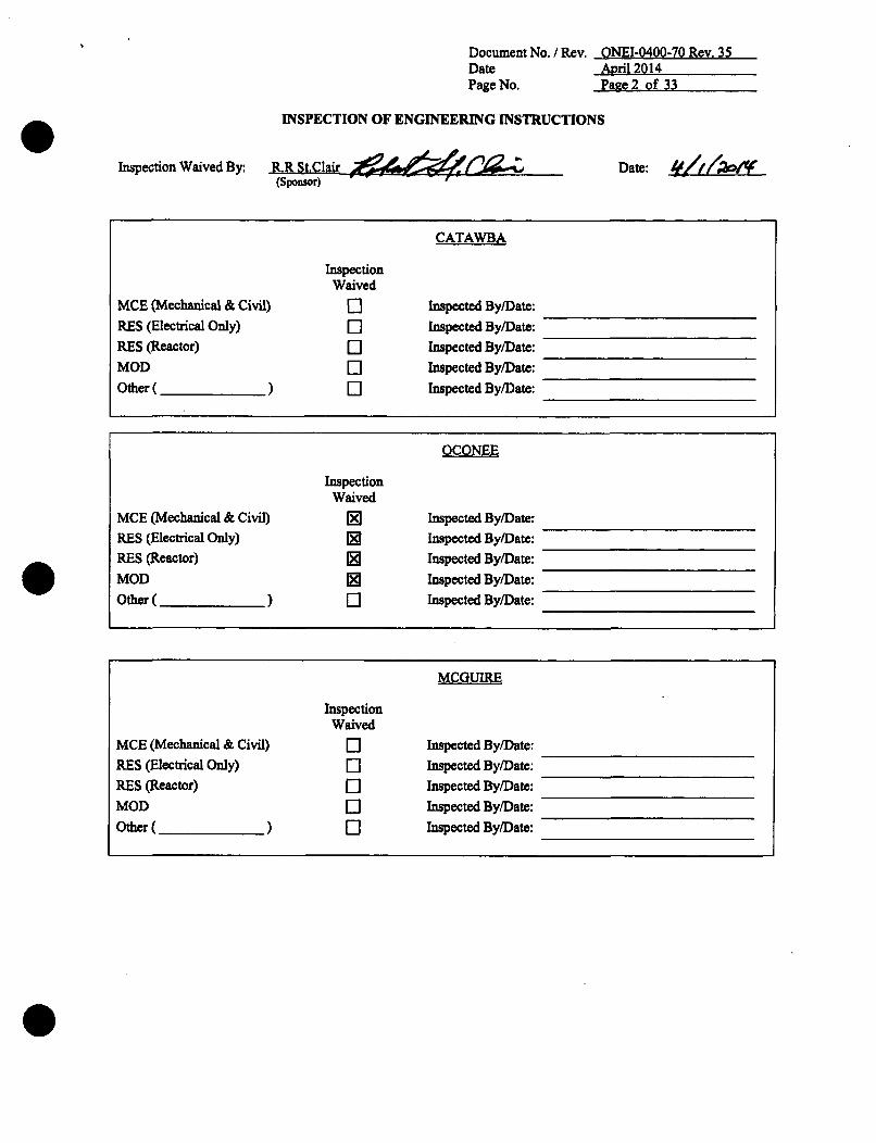
Document No. / Rev. ONEI-0400-70 Rev. 35Date April 2014Page No. Pane 2 of 33
INSPECTION OF ENGINEERING INSTRUCTIONS
R.R St.ClairInspection Waived By. Date: ,h(Sponsor) -----.--
CATAWBA
InspectionWaived
MCE (Mechanical & Civil) I] Inspected By/Date:
RES (Electrical Only) El Inspected By/Date:
RES (Reactor) Inspected By/Date:MOD [] Inspected By/Date:
Other ( ) El Inspected By/Date:
OCONEE
InspectionWaived
MCE (Mechanical & Civil) Inspected By/Date:RES (Electrical Only) Inspected By/Date:RES (Reactor) Inspected By/Date:
MOD [] Inspected By/Date:
Other ( ) El Inspected By/Date:
MCGUIRE
InspectionWaived
MCE (Mechanical & Civil) 11 Inspected By/Date:
RES (Electrical Only) El Inspected By/Date:
RES (Reactor) El Inspected By/Date:
MOD El Inspected By/Date:
Other ( ) El Inspected By/Date:
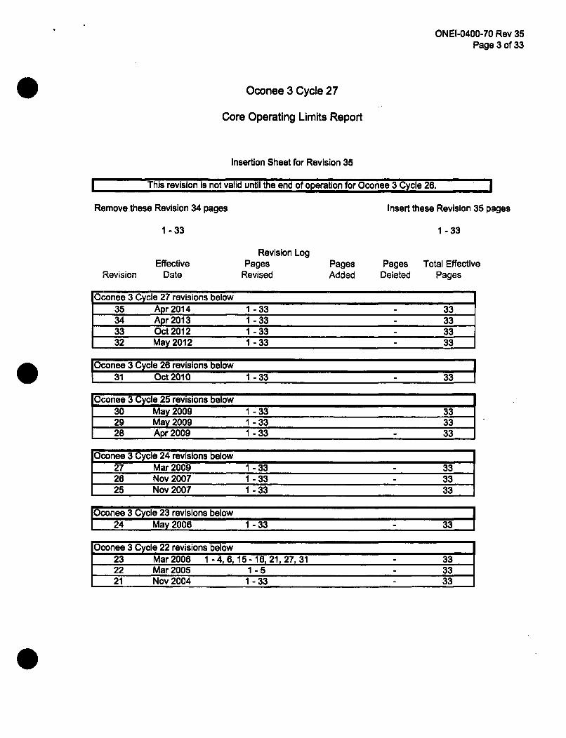
ONEI-0400-70 Rev 35Page 3 of 33
Oconee 3 Cycle 27
Core Operating Limits Report
Insertion Sheet for Revision 35
This revision Is not valid until the end of operation for Oconee 3 Cycle 26.
Remove these Revision 34 pages Insert these Revision 35 pages
1 -33 1 - 33
EffectiveDate
Revision LogPages
RevisedPagesAdded
Pages Total EffectiveDeleted PagesRevision
Oconee 3 Cycle 27 revisions below35 Apr 2014 1-33 - 3334 Apr 2013 1-33 - 3333 Oct 2012 1-33 - 3332 May 2012 1-33 - 33
I conee 3 Cycle 26 revisions below31 Oct 2010 1-33 33
Oconee 3 Cycle 25 revisions below30 May 2009 1-33 3329 May 2009 1-33 3328 Apr2009 1-33 - 33
Oconee 3 Cycle 24 revisions below '__27 Mar 2009 11-33 3326 Nov2007 1-33 - 3325 Nov 2007 1-33 33
IOconee 3 Cycle 23 revisions below24 May 2006 1-33 - 33
Oconee 3 Cycle 22 revisions below23 Mar2006 1 - 4, 6,15 -16, 21 27,31 - 3322 Mar2005 1-5 - 3321 Nov 2004 1-33 - 33
ONEI-0400-70 Rev 35Page 4 of 33
Oconee 3 Cycle 27
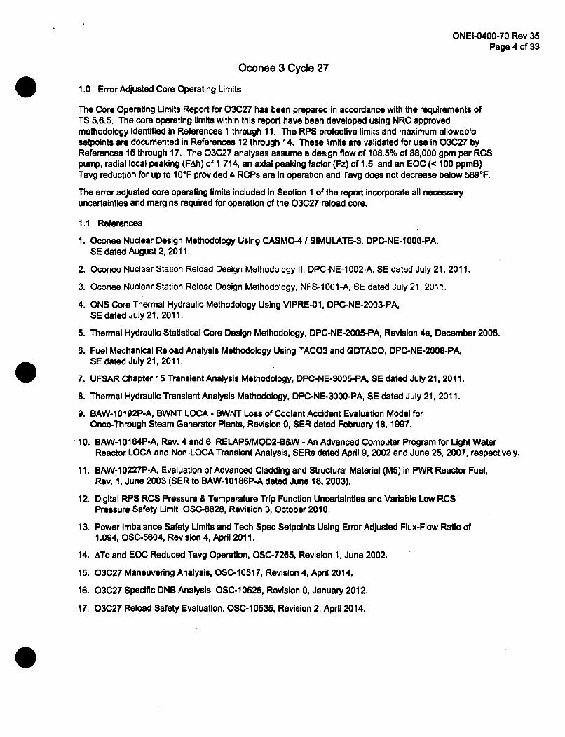
1.0 Error Adjusted Core Operating Limits
The Core Operating Limits Report for 03C27 has been prepared in accordance with the requirements ofTS 5.6.5. The core operating limits within this report have been developed using NRC approvedmethodology identified in References 1 through 11. The RPS protective limits and maximum allowablesetpoints are documented in References 12 through 14. These limits are validated for use In 03C27 byReferences 15 through 17. The 03C27 analyses assume a design flow of 108.5% of 88,000 gpm per RCSpump, radial local peaking (FAh) of 1.714, an axial peaking factor (Fz) of 1.5, and an EOC (< 100 ppmB)Tavg reduction for up to 10°F provided 4 RCPs are in operation and Tavg does not decrease below 569°F.
The error adjusted core operating limits included in Section 1 of the report incorporate all necessaryuncertainties and margins required for operation of the 03C27 reload core.
1.1 References
1. Oconee Nuclear Design Methodology Using CASMO-4 / SIMULATE-3, DPC-NE-1006-PA,SE dated August 2, 2011.
2. Oconee Nuclear Station Reload Design Methodology II, DPC-NE-1002-A, SE dated July 21, 2011.
3. Oconee Nuclear Station Reload Design Methodology, NFS-1001-A, SE dated July 21, 2011.
4. ONS Core Thermal Hydraulic Methodology Using VIPRE-01, DPC-NE-2003-PA,SE dated July 21, 2011.
5. Thermal Hydraulic Statistical Core Design Methodology, DPC-NE-2005-PA, Revision 4a, December 2008.
6. Fuel Mechanical Reload Analysis Methodology Using TACO3 and GDTACO, DPC-NE-2008-PA,SE dated July 21, 2011.
7. UFSAR Chapter 15 Transient Analysis Methodology, DPC-NE-3005-PA, SE dated July 21, 2011.
8. Thermal Hydraulic Transient Analysis Methodology, DPC-NE-3000-PA, SE dated July 21, 2011.
9. BAW-1 01 92P-A, BWNT LOCA - BWNT Loss of Coolant Accident Evaluation Model forOnce-Through Steam Generator Plants, Revision 0, SER dated February 18, 1997.
10. BAW-1 01 64P-A, Rev. 4 and 8, RELAP5/MOD2-B&W - An Advanced Computer Program for Light WaterReactor LOCA and Non-LOCA Transient Analysis, SERs dated April 9, 2002 and June 25, 2007, respectively.
11. BAW-10227P-A, Evaluation of Advanced Cladding and Structural Material (M5) in PWR Reactor Fuel,Rev. 1, June 2003 (SER to BAW-10186P-A dated June 18, 2003).
12. Digital RPS RCS Pressure & Temperature Trip Function Uncertainties and Variable Low RCSPressure Safety Limit, OSC-8828, Revision 3, October 2010.
13. Power Imbalance Safety Limits and Tech Spec Setpoints Using Error Adjusted Flux-Flow Ratio of1.094, OSC-5604, Revision 4, April 2011.
14. ATc and EOC Reduced Tavg Operation, OSC-7265, Revision 1, June 2002.
15. 03C27 Maneuvering Analysis, OSC-10517, Revision 4, April 2014.
16. 03C27 Specific DNB Analysis, OSC-10526, Revision 0, January 2012.
17. 03C27 Reload Safety Evaluation, OSC-10535, Revision 2, April 2014.
ONEI-0400-70 Rev 35Page 5 of 33
Oconee 3 Cycle 27
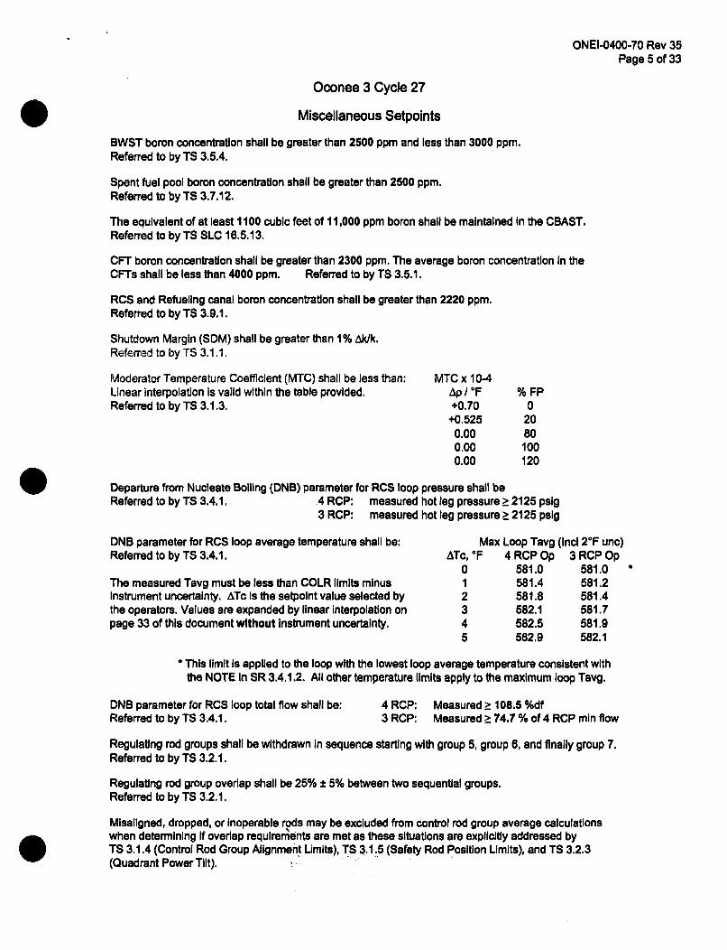
Miscellaneous Setpoints
BWST boron concentration shall be greater than 2500 ppm and less than 3000 ppm.Referred to by TS 3.5.4.
Spent fuel pool boron concentration shall be greater than 2500 ppm.Referred to by TS 3.7.12.
The equivalent of at least 1100 cubic feet of 11,000 ppm boron shall be maintained in the CBAST.Referred to by TS SLC 16.5.13,
CFT boron concentration shall be greater than 2300 ppm. The average boron concentration In theCFTs shall be less than 4000 ppm. Referred to by TS 3.5.1.
RCS and Refueling canal boron concentration shall be greater than 2220 ppm.Referred to by TS 3.9.1.
Shutdown Margin (SDM) shall be greater than 1% Ak/k.Referred to by TS 3.1.1.
Moderator Temperature Coefficient (MTC) shall be less than:Linear interpolation Is valid within the table provided.Referred to by TS 3.1.3.
MTC x 10-4Ap/ =F+0.70
+0.5250.000.000.00
% FP0
2080100120
Departure from Nucleate Boiling (DNB) parameter for RCS loop pressure shall beReferred to by TS 3.4.1. 4 RCP: measured hot leg pressure ?2125 psig
3 RCP: measured hot leg pressure > 2125 pslg
DNB parameter for RCS loop average temperature shall be:Referred to by TS 3.4.1.
The measured Tavg must be less than COLR limits minusInstrument uncertainty. ATc Is the setpoint value selected bythe operators. Values are expanded by linear interpolation onpage 33 of this document without Instrument uncertainty.
Max Loop Tavg (Incl 2°F unc)ATc, OF 4 RCP Op 3 RCP Op
0 581.0 581.01 581.4 581.22 581.8 581.43 582.1 581.74 582.5 581.95 582.9 582.1
* This limit Is applied to the loop with the lowest loop average temperature consistent withthe NOTE In SR 3.4.1.2. All other temperature limits apply to the maximum loop Tavg.
DNB parameter for RCS loop total flow shall be:Referred to by TS 3.4.1.
4 RCP: Measured > 108.5 %df3 RCP: Measured > 74.7 % of 4 RCP min flow
Regulating rod groups shall be withdrawn In sequence starting with group 5, group 6, and finally group 7.Referred to by TS 3.2.1.
Regulating rod group overlap shall be 25% ± 5% between two sequential groups.Referred to by TS 3.2.1.
Misaligned, dropped, or Inoperable rods may be excluded from control rod group average calculationswhen determining If overlap requirements are met as these situations are explicitly addressed byTS 3.1.4 (Control Rod Group Alignment Limits), TS 3.1.5 (Safety Rod Position Limits), and TS 3.2.3(Quadrant Power Tilt).
ONEI-0400-70 Rev 35Page 6 of 33
Oconee 3 Cycle 27
EFPD
0 to 595595 to EOC
Core Power Level, %FP
Full Incore
Out of Core
Backup Incore
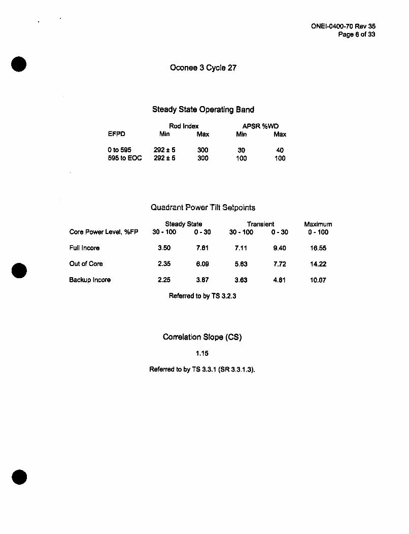
Steady State Operating Band
Rod Index APSR %WDMin Max Min Max
292 t 5 300 30 40292 15 300 100 100
Quadrant Power Tilt Setpoints
Steady State Transient30-100 0-30 30-100 0-30
3.50 7.61 7.11 9.40
2.35 6.09 5.63 7.72
2.25 3.87 3.63 4.81
Referred to by TS 3.2.3
Maximum0-100
16.55
14.22
10.07
Correlation Slope (CS)
1.15
Referred to by TS 3.3.1 (SR 3.3.1.3).

ONEI-0400-70 Rev 35Page 7 of 33
Oconee 3 Cycle 27
Variable Low RCS Pressure RPS Setpoints
Referred to by TS 3.3.1
2400 ,
P =2355 psig T 618F
2300
2200
a.-I 2100 Acceptable
Operation
o.4
SP =11.14 *Tout -4706
2000
Unacceptable1900 Operation
P = 1800 psig1800
T=584 °F
1700 I540 560 580 600 620 640
Reactor Coolant Outlet Temperature, OF
ONEI-0400-70 Rev 35Page 8 of 33
Oconee 3 Cycle 27
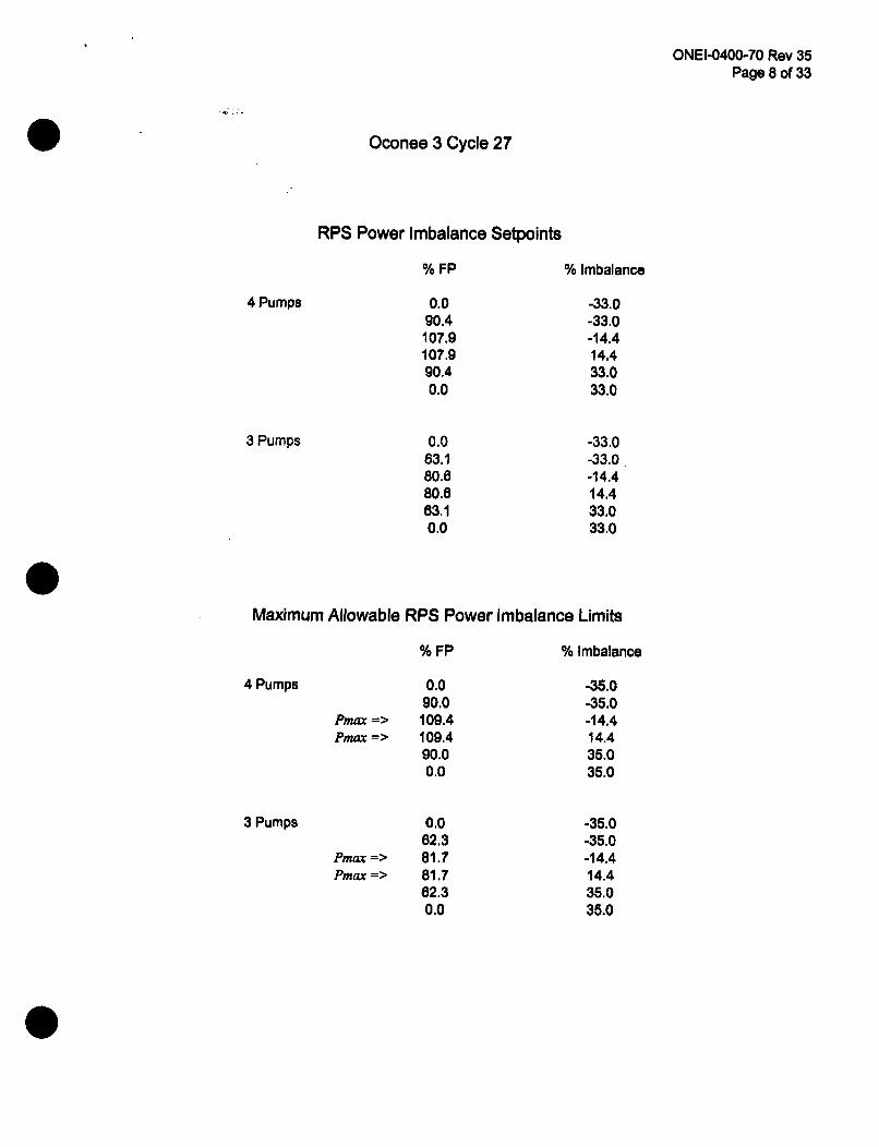
RPS Power Imbalance Setpoints
4 Pumps
% FP
0.090.4
107.9107.990.40.0
% Imbalance
-33.0-33.0-14.414.433.033.0
-33.0-33.0-14.414.433.033.0
3 Pumps 0.063.180.680.663.10.0
Maximum Allowable RPS Power Imbalance Limits
4 Pumps
3 Pumps
% FP
0.090.0
Pmax => 109.4Pmr --> 109.4
90.00.0
0.062.3
/Pmax -> 81.7Pmax => 81.7
62.30.0
% Imbalance
-35.0-35.0-14.414.435.035.0
-35.0-35.0-14.414.435.035.0

ONEI-0400-70 Rev 35Page 9 of 33
Oconee 3 Cycle 27
Operational Power Imbalance Setpoints
4 Pumps
3 Pumps
%FP
0.0
80.0
90.0
100.0
102.0
102.0
100.0
90.0
80.0
0.0
0.0
63.1
63.7
77.0
77.0
63.1
63.1
0.0
FullIncore
-28.0
-28.0
-28.0
-17.8
-15.7
15.7
17.8
28.0
28.0
28.0
-28.0
-28.0
-13.2
13.2
28.0
28.0
BackupIncore
-27.3
-27.3
-27.3
-17.8
-15.7
11.1
14.3
28.0
28.0
28.0
-27.3
-27.3
-13.2
13.2
28.0
28.0
Out ofCore
-28.0
-28.0
-28.0
-17.8
-15.7
11.7
14.9
28.0
28.0
28.0
-28.0
-28.0
-13.2
13.2
28.0
28.0
ONEI-0400-70 Rev 35Page 10 of 33
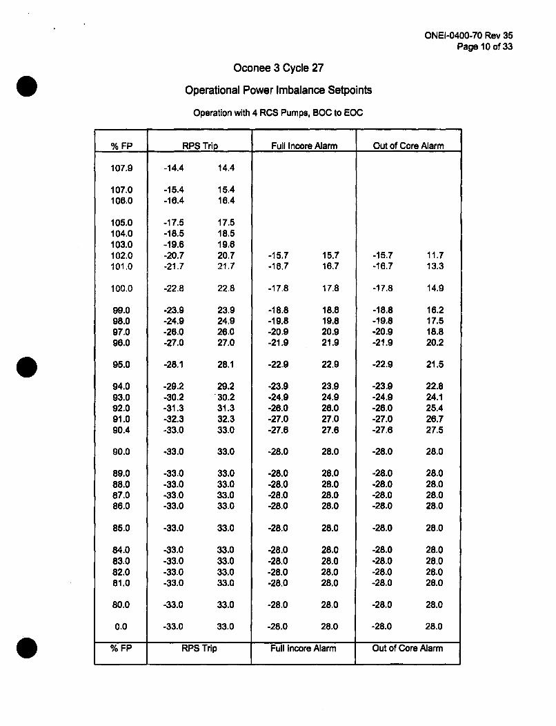
Oconee 3 Cycle 27
Operational Power Imbalance Setpoints
Operation with 4 RCS Pumps, BOC to EOC
% FP RPS Trip Full Incore Alarm Out of Core Alarm
107.9
107.0106.0
105.0104.0103.0102.0101.0
100.0
99.098.097.096.0
95.0
94.093.092.091.090.4
90.0
89.088.087.086.0
85.0
84.083.082.081.0
80.0
0.0
-14.4
-15.4-16.4
-17.5-18.5-19.6-20.7-21.7
-22.8
-23.9-24.9-26.0-27.0
-28.1
-29.2-30.2-31.3-32.3-33.0
-33.0
-33.0-33.0-33.0-33.0
-33.0
-33.0-33.0-33.0-33.0
-33.0
-33.0
14.4
15.416.4
17.518.519.620.721.7
22.8
23.924.926.027.0
28.1
29.230.231.332.333.0
33.0
33.033.033.033.0
33.0
33.033.033.033.0
33.0
33.0
-15.7-18.7
-17.8
-18.8-19.8-20.9-21.9
-22.9
-23.9-24.9-26.0-27.0-27.6
-28.0
-28.0-28.0-28.0-28.0
-28.0
-28.0-28.0-28.0-28.0
-28.0
-28.0
15.716.7
17.8
18.819.820.921.9
22.9
23.924.926.027.027.6
28.0
28.028.028.028.0
28.0
28.028.028.028.0
28.0
28.0
-15.7-16.7
-17.8
-18.8-19.8-20.9-21.9
-22.9
-23.9-24.9-26.0-27.0-27.6
-28.0
-28.0-28.0-28.0-28.0
-28.0
-28.0-28.0-28.0-28.0
-28.0
-28.0
11.713.3
14.9
16.217.518.820.2
21.5
22.824.125.426.727.5
28.0
28.028.028.028.0
28.0
28.028.028.028.0
28.0
28.0
% FP RPS Trip Full Incore Alarm I Out of Core Alarm
ONEI-0400-70 Rev 35Page 11 of 33
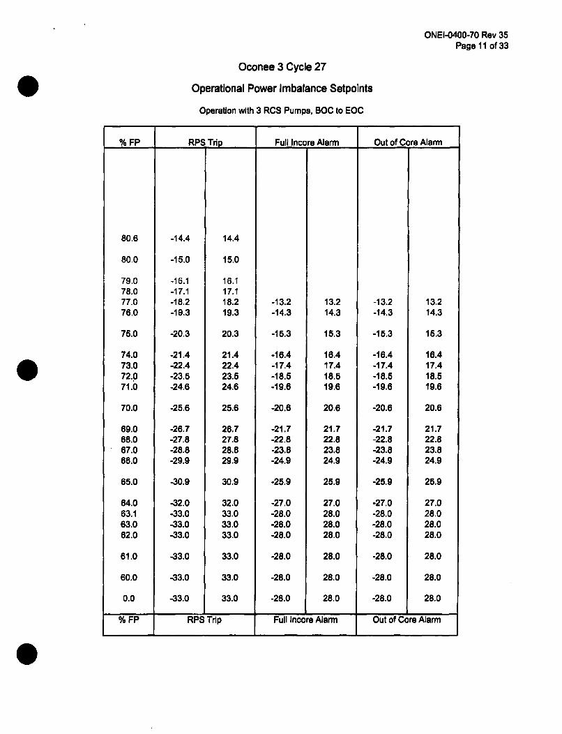
Oconee 3 Cycle 27
Operational Power Imbalance Setpoints
Operation with 3 RCS Pumps, BOC to EOC
% FP RPS Trip Full Incore Alarm Out of Core Alarm
80.6
80.0
79.078.077.076.0
75.0
74.073.072.071.0
70.0
69.068.067.066.0
65.0
64.063.163.062.0
61.0
60.0
0.0
-14.4
-15.0
-16.1-17.1-18.2-19.3
-20.3
-21.4-22.4-23.5-24.6
-25.6
-26.7-27.8-28.8-29.9
-30.9
-32.0-33.0-33.0-33.0
-33.0
-33.0
14.4
15.0
16.117.118.219.3
20.3
21.422.423.524.6
25.6
26.727.828.829.9
30.9
32.033.033.033.0
33.0
33.0
33.0
-13.2-14.3
-15.3
-16.4-17.4-18.5-19.6
-20.6
-21.7-22.8-23.8-24.9
-25.9
-27.0-28.0-28.0-28.0
-28.0
-28.0
13.214.3
15.3
16.417.418.519.6
20.6
21.722.823.824.9
25.9
27.028.028.028.0
28.0
28.0
28.0
-13.2-14.3
-15.3
-16.4-17.4-18.5-19.6
-20.6
-21.7-22.8-23.8-24.9
-25.9
-27.0-28.0-28.0-28.0
-28.0
-28.0
-28.0
13.214.3
15.3
18.417.418.519.6
20.6
21.722.823.824.9
25.9
27.028.028.028.0
28.0
28.0
28.0-33.0 -28.0
% FP RPS Trip Full Incore Alarm Out of Core Alarm
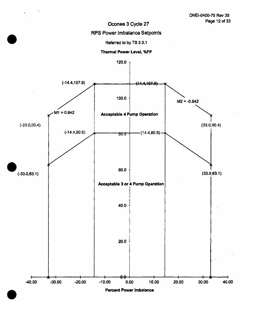
Oconee 3 Cycle 27
RPS Power Imbalance Setpoints
Referred to by TS 3.3.1
Thermal Power Level, %FP
120.0 1
(-14.4,107.9) 14A A 4IA*1"#%U
M1 = 0.942
ONEI-0400-70 Rev 35Page 12 of 33
M2 = -0.942
(33.0,90.4)
(33.0,63.1)
100.0
Acceptable 4 Pump Operation
(-33.0,90.4)
(-33.0,63.1)
(-14.4,80.'6) s m,. (14.4,80.6)--
60.0
Acceptable 3 or 4 Pump Operation
I
40.0
20.0
I-40.00 -30.00 -20.00 -10.00 0.00 10.00
Percent Power Imbalance
20.00 30.00 40.00
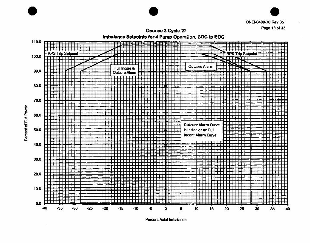
Oconee 3 Cycle 27Imbalance Setpoints for 4 Pump Operation, BOC to EOC
ONEI-0400-70 Rev 35
Page 13 of 33
. .. T . . . . . . . . .RPS Trip Setpoint • I- -H-
110.0
100.0
90.0
IRPS TriD SetDoint
Full Incore &lOutcore Alarm
I Outcore Alarm
80.0
70.0
160.0
o.
40.0
30.0
20.0
10.0
Outcore Alarm Curveis inside or on FullIncore Alarm Curve
0.0 w-40 -35 -30 -25 -20 -15 -10 -5 0 5 10 15 20 25 30 35 40
Percent Axial Imbalance

ONEI-0400-70 Rev 35
Page 14 of 33Oconee 3 Cycle 27
Imbalance Setpoints for 3 Pump Operation, BOC to EOC110
100
90
LA.
80
70
60
50
40
30
20
10
RPS Trip Setpoint ' RPS Trip Setpoint ý
Full Incore & ,Outcore Alarm -
I F
i[ i
-15 -0 -5 0 5 0 15 20 2
-40 -35 -30 -25 -20 35 40
Percent Axial Imbalance
ONEI-0400-70 Rev 35Page 15 of 33
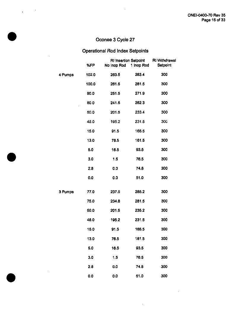
Oconee 3 Cycle 27
4 Pumps
3 Pumps
Operational Rod Index Setpoints
RI Insertion Setpolnt%FP No Inop Rod 1 Inop Rod
102.0 263.5 283.4
100.0 261.5 281.5
90.0 251.5 271.9
80.0 241.5 262.3
50.0 201.5 233.4
48.0 195.2 231.5
15.0 91.5 165.5
13.0 78.5 161.5
5.0 16.5 93.5
3.0 1.5 76.5
2.8 0.0 74.8
0.0 0.0 51.0
RI WithdrawalSetpoint
300
300
300
300
300
300
300
300
300
300
300
300
300
300
300
300
300
300
300
300
300
300
77.0
75.0
50.0
48.0
15.0
13.0
5.0
3.0
2.8
0.0
237.5
234.8
201.5
195.2
91.5
76.5
16.5
1.5
0.0
0.0
285.2
281.5
235.2
231.5
165.5
161.5
93.5
76.5
74.8
51.0
ONEI-0400-70 Rev 35Page 16 of 33
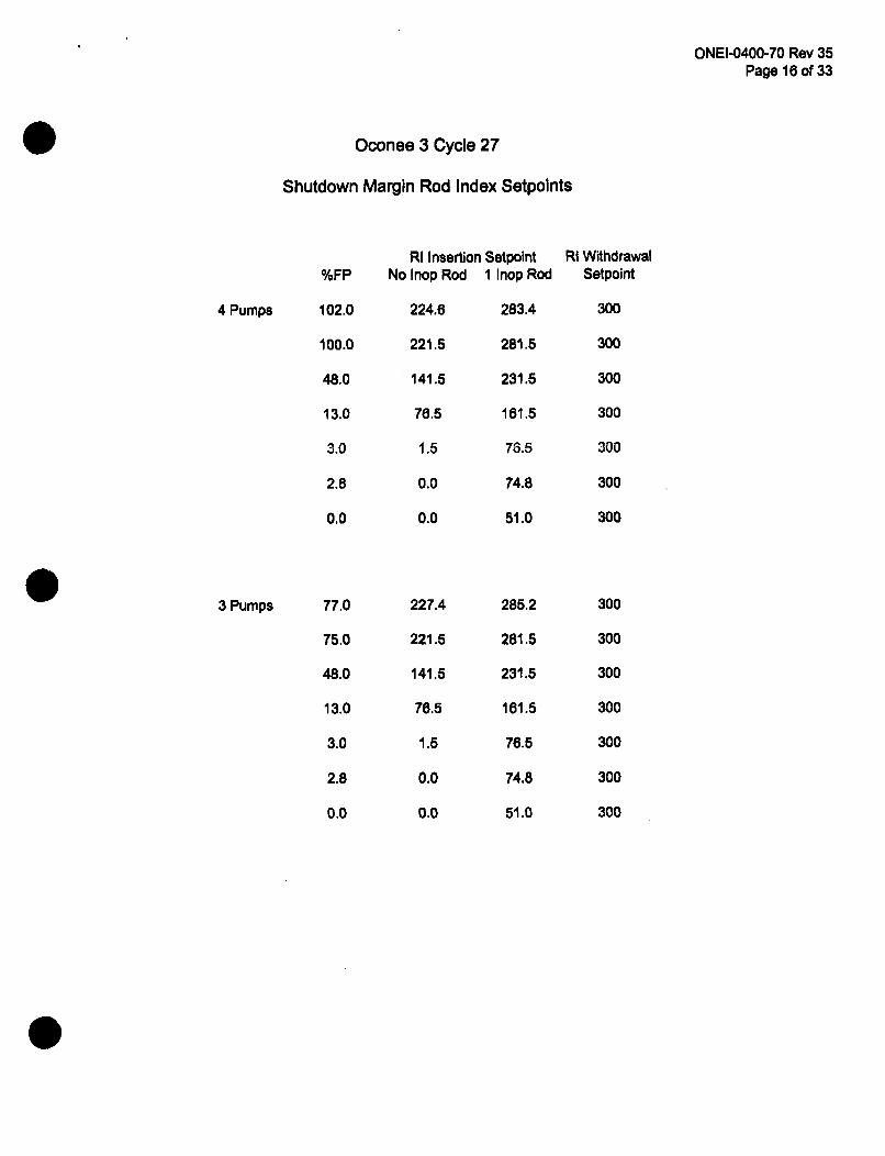
Oconee 3 Cycle 27
Shutdown Margin Rod Index Setpoints
4 Pumps
3 Pumps
%FP
102.0
100.0
48.0
13.0
3.0
2.8
0.0
77.0
75.0
48.0
13.0
3.0
2.8
0.0
RI Insertion SetpointNo Inop Rod I Inop Rod
224.6 283.4
221.5 281.5
141.5 231.5
76.5 161.5
1.5 76.5
0.0 74.8
0.0 51.0
RI WithdrawalSetpoint
300
300
300
300
300
300
300
300
300
300
300
300
300
300
227.4
221.5
141.5
76.5
1.5
0.0
0.0
285.2
281.5
231.5
161.5
76.5
74.8
51.0
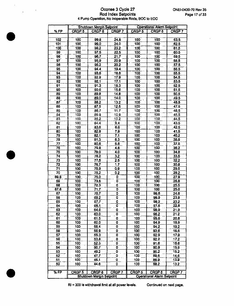
Oconee 3 Cycle 27Rod Index Setpoints
4 Pump Operation, No Inoperable Rods, BOC to EOC
ONEI-0400-70 Rev 35Page 17 of 33
Shutdown Margin Setvoint Operational Alarm Setpoint% FP CRGP 5 CRGP 6 CRGP 7 CRGP 5 CRGP 6 CRGP 7
102 100 99.8 24.8 100 100 83.5101 100 99.0 24.0 100 100 62.5100 100 98.2 23.2 100 100 61.599 100 97.5 22.5 100 100 60.598 100 96.7 21.7 100 100 59.597 100 95.9 20.9 100 100 58.596 100 95.2 20.2 100 100 57.595 100 94.4 19.4 100 100 56.594 100 93.6 18.6 100 100 55.593 100 92.9 17.9 100 100 54.592 100 92.1 17.1 100 100 53.591 100 91.3 16.3 100 100 52.590 100 90.8 15.8 100 100 51.589 100 89.8 14.8 100 100 50.588 100 89.0 14.0 100 100 49.587 100 88.2 13.2 100 100 48.586 100 87.5 12.5 100 100 47.585 100 86.7 11.7 100 100 46.584 100 85.9 10.9 100 100 45.583 100 85.2 10.2 100 100 44.582 100 84.4 9.4 100 100 43.581 100 83.6 8.6 100 100 42.580 100 82.9 7.9 100 100 41.579 100 82.1 7.1 100 100 40.278 100 81.3 6.3 100 100 38.877 100 80.6 5.6 100 100 37.578 100 79.8 4.8 100 100 36.275 100 79.0 4.0 100 100 34.874 100 78.2 3.2 100 100 33.573 100 77.5 2.5 100 100 32.272 100 76.7 1.7 100 100 30.871 100 75.9 0.9 100 100 29.570 100 75.2 0.2 100 100 28.2
69.8 100 75.0 0 100 100 27.969 100 73.8 0 100 100 26.868 100 72.3 0 100 100 25.5
67.6 100 71.7 0 100 100 25.087 100 70.7 0 100 99.6 24.686 100 69.2 0 100 98.9 23.965 100 67.7 0 100 98.2 23.264 100 66.1 0 100 97.6 22.863 100 64.6 0 100 96.9 21.962 100 63.0 0 100 96.2 21.261 100 61.5 0 100 95.6 20.660 100 60.0 0 100 94.9 19.959 100 58.4 0 100 94.2 19.258 100 56.9 0 100 93.6 18.857 100 55.3 0 100 92.9 17.956 100 53.8 0 100 92.2 17.255 100 52.3 0 100 91.6 16.654 100 50.7 0 100 90.9 15.953 100 49.2 0 100 90,2 15.252 100 47.7 0 100 89.6 14.651 100 46.1 0 100 88.9 13.950 100 44.6 0 100 88.2 13.2
%FP CRGP5 CRGP6 CRGP7 CRGP5 CRGP6 CRGP7d Shutdown Margin Setpoint Operational Alarm Setpoint
RI = 300 Is withdrawal limit at all power levels. Continued on next page.
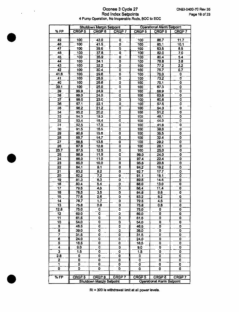
Oconee 3 Cycle 27Rod Index Setpoints
4 Pump Operation, No Inoperable Rods, BOC to EOC
ONEI-0400-70 Rev 35Page 18 of 33
Shutdown Margin Setpolnt Operational Alarm Setpoint% FP CRGP 5 CRGP 6 CRGP 7 CRGP 5 CRGP 6 CRGP 7
49 100 43.0 0 100 88.7 11.748 100 41.5 0 100 85.1 10.147 100 39.6 0 100 83.5 8.546 100 37.8 0 100 82.0 7.045 100 35.9 0 100 80.4 5.444 100 34.1 0 100 78.8 3.843 100 32.2 0 100 77.2 2.242 100 30.4 0 100 75.7 0.7
41.6 100 29.6 0 100 75.0 041 100 28.5 0 100 73.2 040 100 26.6 0 100 70.1 0
39.1 100 25.0 0 100 67.3 039 99.9 24.9 0 100 66.9 038 99.0 24.0 0 100 63.8 037 98.0 23.0 0 100 60.6 036 97.1 22.1 0 100 57.5 035 96.2 21.2 0 100 54.3 034 95.2 20.2 0 100 51.2 0
33 94.3 19.3 0 100 48.1 032 93.4 18.4 0 100 44.9 031 92.5 17.5 0 100 41.8 030 91.5 16.5 0 100 38.8 029 90.6 15.6 0 100 35.5 028 89.7 14.7 0 100 32.4 027 88.8 13.8 0 100 29.2 026 87.8 12.8 0 100 26.1 0
25.7 87.5 12.5 0 100 25.0 025 86.9 11.9 0 99.0 24.0 024 86.0 11.0 0 97.4 22.4 023 85.0 10.0 0 95.8 20.8 022 84.1 9.1 0 94.2 19.2 021 83.2 8.2 0 92.7 17.7 020 82.2 7.2 0 91.1 16.1 019 81.3 6.3 0 89.5 14.5 018 80.4 5.4 0 88.0 13.0 017 79.5 4.5 0 86.4 11.4 018 78.5 3.5 0 84.8 9.8 015 77.6 2.6 0 83.2 8.2 014 76.7 1.7 0 79.5 4.5 013 75.8 0.8 0 75.8 0.8 0
12.8 75.0 0 0 75.0 0 012 69.0 0 0 69.0 0 011 61.5 0 0 81.5 0 010 54.0 0 0 54.0 0 09 46.5 0 0 46.5 0 08 39.0 0 0 39.0 0 07 31.5 0 0 31.5 0 06 24.0 0 0 24.0 0 05 16.5 0 0 18.5 0 04 9.0 0 0 9.0 0 03 1.5 0 0 1.5 0 0
2.8 0 0 0 0 0 02 0 0 0 0 0 01- 0 0 0 0 0 00 0 0 0 0 0 0
% FP CRGP 5 CRGP6 CRGP7 CRGP5 CRGP6 CRGP7Shutdown Margin Setpolnt Operational Alarm Setpoint
RI = 300 is withdrawal limit at all power levels.
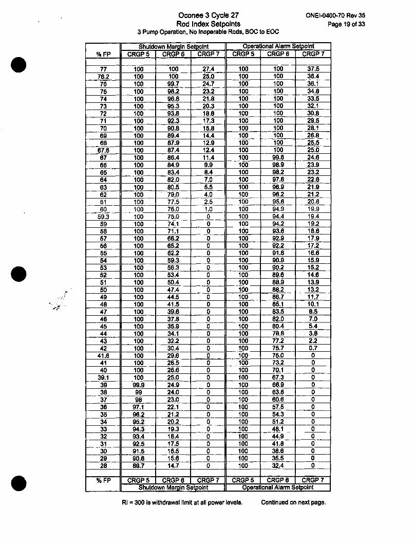
Oconee 3 Cycle 27Rod Index Setpolnts
3 Pump Operation, No Inoperable Rods, BOC to EOC
ONEI-0400-70 Rev 35Page 19 of 33
Shutdown Margin Setpolnt Operational Alarm Setpolnt% FP CRGP 5 CRGP 6 CRGP 7 CRGP 5 CRGP 6 CRGP 7
77 100 100 27.4 100 100 37.576.2 100 100 25.0 100 100 36.476 100 99.7 24.7 100 100 36.175 100 98.2 23.2 100 100 34.874 100 96.8 21.8 100 100 33.573 100 95.3 20.3 100 100 32.172 100 93.8 18.8 100 100 30.871 100 92.3 17.3 100 100 29.570 100 90.8 15.8 100 100 28.169 100 89.4 14.4 100 100 26.868 100 87.9 12.9 100 100 25.5
67.6 100 87.4 12.4 100 100 25.067 100 86.4 11.4 100 99.6 24.666 100 84.9 9.9 100 98.9 23.965 100 83.4 8.4 100 98.2 23.264 100 82.0 7.0 100 97.6 22.663 100 80.5 5.5 100 96.9 21.962 100 79.0 4.0 100 96.2 21.261 100 77.5 2.5 100 95.6 20.660 100 76.0 1.0 100 94.9 19.9
59.3 100 75.0 0 100 94.4 19.459 100 74.1 0 100 94.2 19.258 100 71.1 0 100 93.6 18.657 100 68.2 0 100 92.9 17.956 100 65.2 0 100 92.2 17.255 100 62.2 0 100 91.6 16.654 100 59.3 0 100 90.9 15.953 100 56.3 0 100 90.2 15.252 100 53A 0 100 89.6 14.651 100 50.4 0 100 88.9 13.950 100 47.4 0 100 88.2 13.249 100 44.5 0 100 86.7 11.748 100 41.5 0 100 85.1 10.147 100 39.6 0 100 83.5 8.546 100 37.8 0 100 82.0 7.045 100 35.9 0 100 80.4 5.444 100 34.1 0 100 78.8 3.843 100 32.2 0 100 77.2 2.242 100 30.4 0 100 75.7 0.7
41.6 100 29.6 0 100 75.0 041 100 28.5 0 100 73.2 040 100 26.6 0 100 70.1 0
39.1 100 25.0 0 100 67.3 039 99.9 24.9 0 100 66.9 038 99 24.0 0 100 63.8 037 98 23.0 0 100 60.6 036 97.1 22.1 0 100 57.5 035 96.2 21.2 0 100 54.3 034 95.2 20.2 0 100 51.2 033 94.3 19.3 0 100 48.1 032 93.4 18.4 0 100 44.9 031 92.5 17.5 0 100 41.8 030 91.5 16.5 0 100 38.6 029 90.6 15.6 0 100 35.5 028 89.7 14.7 0 100 32.4 0
% FP CRGP5 CRGP6 CRGP7 CRGP5 CRGP6 CRGP 7Shutdown Margin Setpoint Operational Alarm Setpoint
RI = 300 is withdrawal limit at all power levels. Continued on next page.
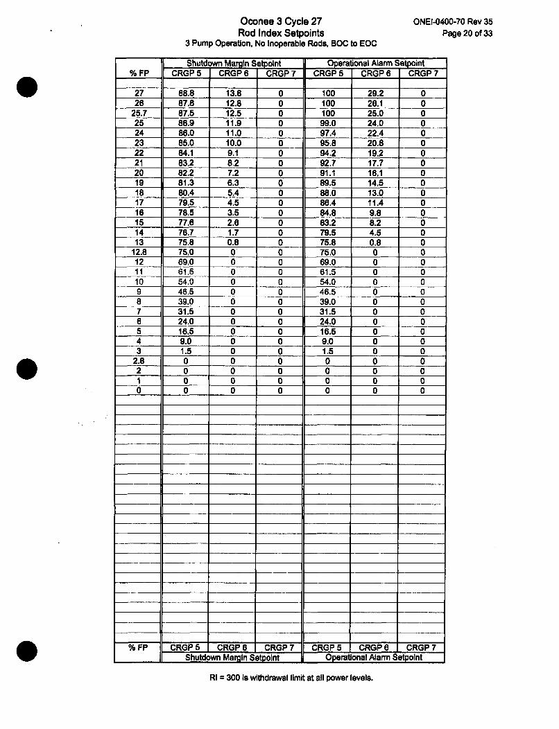
Oconee 3 Cycle 27Rod Index Setpoints
3 Pump Operation, No Inoperable Rods, BOC to EOC
ONEI-0400-70 Rev 35
Page 20 of 33
Shutdown Margin Setpolnt Operational Alarm Setpoint% FP CRGP 5 CRGP 6 CRGP 7 CRGP 5 CRGP 6 CRGP 7
27 88.8 13.8 0 100 29.2 026 87.8 12.8 0 100 26.1 0
25.7 87.5 12.5 0 100 25.0 025 86.9 11.9 0 99.0 24.0 024 86.0 11.0 0 97.4 22.4 023 85.0 10.0 0 95.8 20.8 022 84.1 9.1 0 94.2 19.2 021 83.2 8.2 0 92.7 17.7 020 82.2 7.2 0 91.1 16.1 019 81.3 6.3 0 89.5 14.5 018 80.4 5.4 0 88.0 13.0 017 79.5 4.5 0 86.4 11.4 016 78.5 3.5 0 84.8 9.8 015 77.6 2.6 0 83.2 8.2 014 76.7 1.7 0 79.5 4.5 013 75.8 0.8 0 75.8 0.8 0
12.8 75.0 0 0 75.0 0 012 69.0 0 0 69.0 0 011 61.5 0 0 61.5 0 010 54.0 0 0 54.0 0 09 46.5 0 0 46.5 0 08 39.0 0 0 39.0 0 07 31.5 0 0 31.5 0 06 24.0 0 0 24.0 0 05 16.5 0 0 16.5 0 04 9.0 0 0 9.0 0 03 1.5 0 0 1.5 0 0
2.8 0 0 0 0 0 02 0 0 0 0 0 01 0 0 0 0 0 00 0 0 0 0 0 0
% FP CRGP5 CRGP6 CRGP7 CRGP5 CRGP6 CRGP7_ _ Shutdown Margin Setpolnt Operational Alarm Setpoint
RI = 300 is withdrawal limit at all power levels.
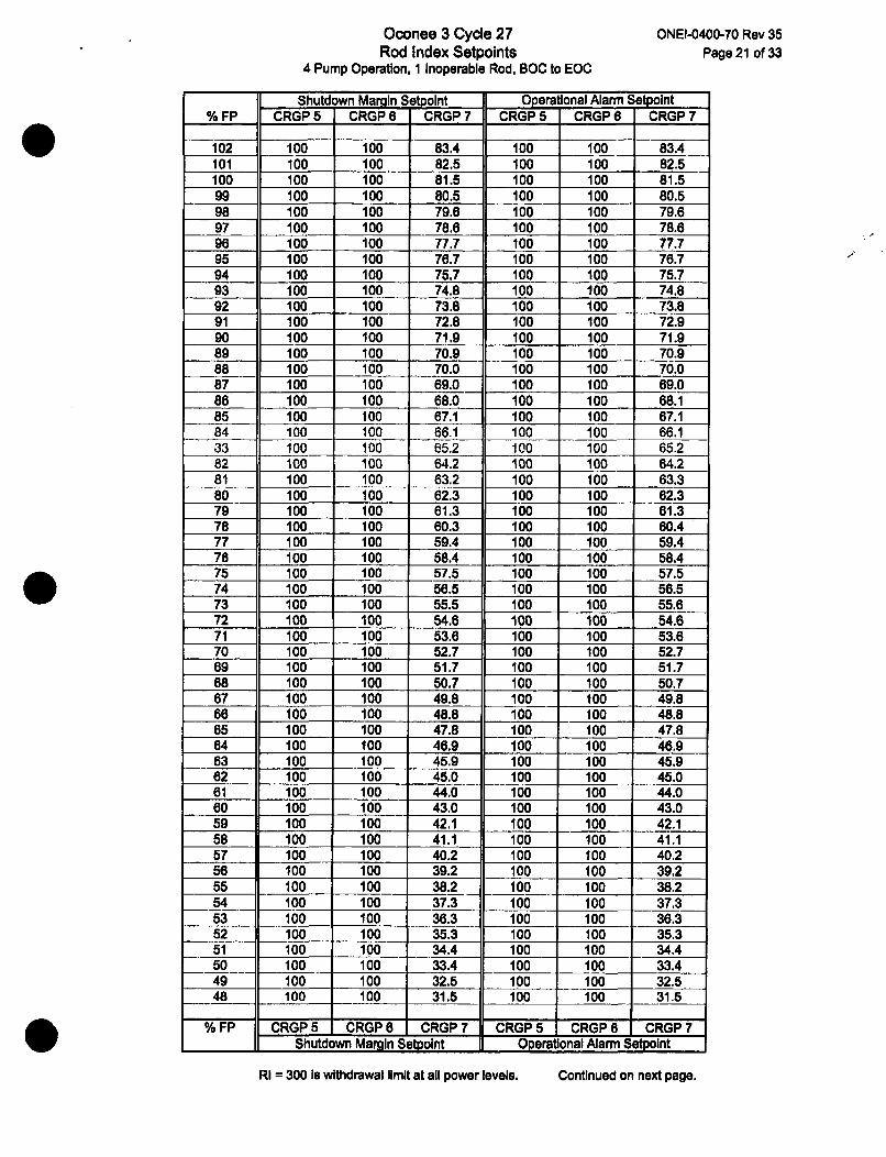
Oconee 3 Cycle 27Rod Index Setpoints
4 Pump Operation, 1 Inoperable Rod, BOC to EOC
ONEI-0400-70 Rev 35
Page 21 of 33
Shutdown Marmin Setpoint Operational Alarm Setpoint% FP CRGP 5 CRGP 6 CRGP7 CRGP 5 CRGP 6 CRGP 7
102 100 100 83.4 100 100 83.4101 100 100 82.5 100 100 82.5100 100 100 81.5 100 100 81.599 100 100 80.5 100 100 80.598 100 100 79.6 100 100 79.697 100 100 78.6 100 100 78.696 100 100 77.7 100 100 77.795 100 100 76.7 100 100 76.794 100 100 75.7 100 100 75.793 100 100 74.8 100 100 74.892 100 100 73.8 100 100 73.891 100 100 72.8 100 100 72.990 100 100 71.9 100 100 71.989 100 100 70.9 100 100 70.988 100 100 70.0 100 100 70.087 100 100 69.0 100 100 69.086 100 100 68.0 100 100 68.185 100 100 67.1 100 100 67.184 100 100 66.1 100 100 66.133 100 100 65.2 100 100 65.282 100 100 64.2 100 100 64.281 100 100 63.2 100 100 63.380 100 100 62.3 100 100 62.379 100 100 61.3 100 100 61.378 100 100 60.3 100 100 60.477 100 100 59.4 100 100 59.476 100 100 58.4 100 100 58.475 100 100 57.5 100 100 57.574 100 100 56.5 100 100 56.573 100 100 55.5 100 100 55.672 100 100 54.6 100 100 54.671 100 100 53.6 100 100 53.670 100 100 52.7 100 100 52.769 100 100 51.7 100 100 51.768 100 100 50.7 100 100 50.767 100 100 49.8 100 100 49.866 100 100 48.8 100 100 48.865 100 100 47.8 100 100 47.864 100 100 46.9 100 100 46.963 100 100 45.9 100 100 45.962 100 100 45.0 100 100 45.061 100 100 44.0 100 100 44.060 100 100 43.0 100 100 43.059 100 100 42.1 100 100 42.158 100 100 41.1 100 100 41.157 100 100 40.2 100 100 40.256 100 100 39.2 100 100 39.255 100 100 38.2 100 100 38.254 100 100 37.3 100 100 37.353 100 100 36.3 100 100 36.352 100 100 35.3 100 100 35.351 100 100 34.4 100 100 34.450 100 100 33.4 100 100 33.449 100 100 32.5 100 100 32.548 100 100 31.5 100 100 31.5
% FP CRGP 5 CRGP6 CRGP7 CRGP5 CRGP6 CRGP7Shutdown Margin Setpolnt Operational Alarm Setpoint
RI = 300 is withdrawal limit at all power levels. Continued on next page.
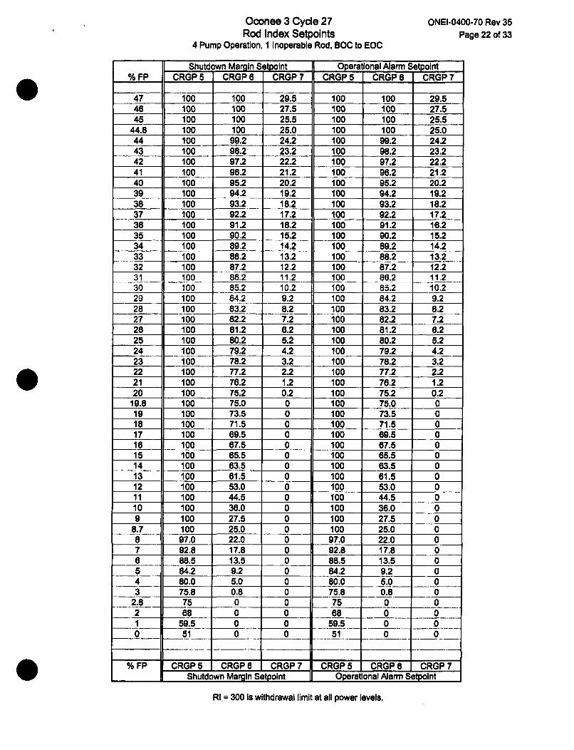
Oconee 3 Cycle 27Rod Index Setpoints
4 Pump Operation, 1 Inoperable Rod, BOC to EOC
ONEI-0400-70 Rev 35Page 22 of 33
Shutdown Margin Setpoint Operational Alarm Setpoint% FP CRGP 5 CRGP 6 CRGP 7 CRGP 5 CRGP 6 CRGP7
47 100 100 29.5 100 100 29.546 100 100 27.5 100 100 27.545 100 100 25.5 100 100 25.5
44.8 100 100 25.0 100 100 25.044 100 99.2 24.2 100 99.2 24.243 100 -- 98.2 23.2 100 98.2 23.242 100 97.2 22.2 100 97.2 22.241 100 96.2 21.2 100 96.2 21.240 100 95.2 20.2 100 95.2 20.239 100 94.2 19.2 100 94.2 19.238 100 93.2 18.2 100 93.2 18.237 100 92.2 17,2 100 92.2 17.236 100 91.2 16.2 100 91.2 16.235 100 90.2 15.2 100 90.2 15.234 100 89.2 14.2 100 89.2 14.233 100 88.2 13.2 100 88.2 13.232 100 87.2 12.2 100 87.2 12.231 100 86.2 11.2 100 86.2 11.230 100 85.2 10.2 100 85.2 10.229 100 84.2 9.2 100 84.2 9.228 100 83.2 8.2 100 83.2 8.227 100 82.2 7.2 100 82.2 7.228 100 81.2 6.2 100 81.2 6.225 100 80.2 5.2 100 80.2 5.224 100 79.2 4.2 100 79.2 4.223 100 78.2 3.2 100 78.2 3.222 100 77.2 2.2 100 77.2 2.221 100 76.2 1.2 100 76.2 1.220 100 75.2 0.2 100 75.2 0.2
19.8 100 75.0 0 100 75.0 019 100 73.5 0 100 73.5 018 100 71.5 0 100 71.5 017 100 69.5 0 100 69.5 016 100 67.5 0 100 67.5 015 100 65.5 0 100 65.5 014 100 63.5 0 100 63.5 013 100 61.5 0 100 61.5 012 100 53.0 0 100 53.0 011 100 44.5 0 100 44.5 010 100 36.0 0 100 36.0 09 100 27.5 0 100 27.5 0
8.7 100 25.0 0 100 25.0 08 97.0 22.0 0 97.0 22.0 07 92.8 17.8 0 92.8 17.8 06 88.5 13.5 0 88.5 13.5 05 84.2 9.2 0 84.2 9.2 04 80.0 5.0 0 80.0 5.0 03 75.8 0.8 0 75.8 0.8 0
2.8 75 0 0 75 0 02 68 0 0 68 0 01 59.5 0 0 59.5 0 00 51 0 0 5100 0
% FP CRGP 5 CRGP65 CRGP 7 CRGP5 CRGP6 CRGP7Shutdown Margin Setpoint Operational Alarm Setpoint
RI = 300 is withdrawal limit at all power levels.

Oconee 3 Cycle 27Rod Index Setpoints
3 Pump Operation, 1 Inoperable Rod, BOC to EOC
ONEI-0400-70 Rev 35
Page 23 of 33
Shutdown Margin Setpolnt OperatIonal Alarm Setpoint% FP CRGP5 CRGP6 CRGP7 CRGP5 CRGP6 CRGP7
77 100 100 85.2 100 100 85.278 100 100 83.4 100 100 83.475 100 100 81.5 100 100 81.574 100 100 79.6 100 100 79.673 100 100 77.8 100 100 77.872 100 100 75.9 100 100 75.971 100 100 74.1 100 100 74.170 100 100 72.2 100 100 72.269 100 100 70.4 100 100 70.468 100 100 68.5 100 100 68.567 100 100 66.7 100 100 66.765 100 100 64.8 100 100 64.865 100 100 63.0 100 100 63.064 100 100 61.1 100 100 61.163 100 100 59.3 100 100 59.362 100 100 57.4 100 100 57.461 100 100 55.6 100 100 55.660 100 100 53.7 100 100 53.759 100 100 51.9 100 100 51.958 100 100 50.0 100 100 50.057 100 100 48.2 100 100 48.256 100 100 46.3 100 100 46.355 100 100 44.5 100 100 44.554 100 100 42.6 100 100 42.653 100 100 40.8 100 100 40.852 100 100 38.9 100 100 38.951 100 100 37.1 100 100 37.150 100 100 35.2 100 100 35.249 100 100 33.4 100 100 33.448 100 100 31.5 100 100 31.547 100 100 29.5 100 100 29.546 100 100 27.5 100 100 27.545 100 100 25.5 100 100 25.5
44.8 100 100 25.0 100 100 25.044 100 99.2 24.2 100 99.2 24.243 100 98.2 23.2 100 98.2 23.242 100 97.2 22.2 100 97.2 22.241 100 96.2 21.2 100 96.2 21.240 100 95.2 20.2 100 95.2 20.239 100 94.2 19.2 100 94.2 19.238 100 93.2 18.2 100 93.2 18.237 100 92.2 17.2 100 92.2 17.236 100 91.2 16.2 100 91.2 16.235 100 90.2 15.2 100 90.2 15.234 100 89.2 14.2 100 89.2 14.233 100 88.2 13.2 100 88.2 13.232 100 87.2 12.2 100 87.2 12.231 100 86.2 11.2 100 86.2 11.230 100 85.2 10.2 100 85.2 10.229 100 84.2 9.2 100 84.2 9.228 100 83.2 8.2 100 83.2 8.227 100 82.2 7.2 100 82.2 7.226 100 81.2 6.2 100 81.2 6.225 100 80.2 5.2 100 80.2 5.224 100 79.2 4.2 100 79.2 4.2
% FP CRGP5 CRGP6 CRGP7 CRGP 5 CRGP 6 CRGP 7Shutdown Margin Setpolnt Operational Alarm Setpoint
RI = 300 is withdrawal limit at all power levels. Continued on next page.
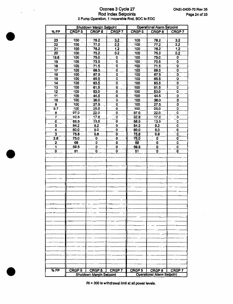
Oconee 3 Cycle 27Rod Index Setpoints
3 Pump Operation, I Inoperable Rod, BOC to EOC
ONEI-0400-70 Rev 35Page 24 of 33
Shutdown Margin Setpolnt Operational Aiarm Setpolnt% FP CRGP 5 CRGP 6 CRGP 7 CRGP 5 CRGP 6 CRGP 7
23 100 78.2 3.2 100 78.2 3.222 100 77.2 2.2 100 77.2 2.221 100 76.2 1.2 100 78.2 1.220 100 75.2 0.2 100 75.2 0.2
19.8 100 75.0 0 100 75.0 019 100 73.5 0 100 73.5 018 100 71.5 0 100 71.5 017 100 69.5 0 100 69.5 016 100 67.5 0 100 67.5 015 100 65.5 0 100 65.5 014 100 63.5 0 100 63.5 013 100 61.5 0 100 61.5 012 100 53.0 0 100 53.0 011 100 44.5 0 100 44.5 010 100 36.0 0 100 36.0 09 100 27.5 0 100 27.5 0
8.7 100 25.0 0 100 25.0 08 97.0 22,0 0 97.0 22.0 07 92.8 17.8 0 92.8 17.8 06 88.5 13.5 0 88.5 13.5 05 84.2 9.2 0 84.2 9.2 04 80.0 5.0 0 80.0 5.0 03 75.8 0.8 0 75.8 0.8 0
2.8 75.0 0 0 75.0 0 02 68 0 0 68 0 01 59.5 0 0 59.5 0 00 51 0 0 51 0 0
U I -I' -II* + I
- II 4 4-- -II 4- I
HI i -i HII +
% FP CRGP5 CRGP6 CRGPZ7 CRGP5 CRGP6 CRGP7Shutdown Margin SetpoInt Operational Alarm Setpoint
RI = 300 is withdrawal limit at all power levels.
I .5
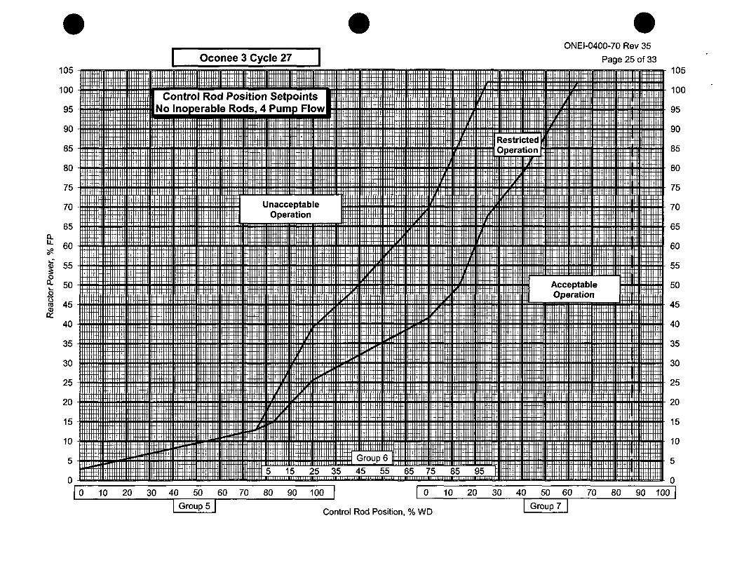
I Oconee 3 Cycle 27 IONEI-0400-70 Rev 35
Page 25 of 33105
100 Control Rod Position Setpoints95 No Inoperable Rods, 4 Pump Flov
105
100
95
90
85
0-
LL
ca~
90
85
80
75
70
65
60
55
50
45
40
35
30
25
MU
80
75
4
UnacceptableOperation
I
AcceptableOperation I
I0
70
65
60
55
50
45
40
35
30
25
2020
15
10
5
0
H 15
10
i2 Group 6 H M15 5 25 35 45 55 65 75 85 95 1
5
0w wL - I ... III- I'm ........................ ........ ..........
10 10 20 30 40 50 60 70 80 90 100 I ( 0 10 20 30 40 50 60 70 80 90 1001I Group 5 I Group 7
Control Rod Position, % WD

ONEI-0400-70 Rev 35
1Page 26 of 3310 Oconee 3 Cycle 27105
100 Control Rod Position SetpointII UNo Inoperable Rods, 3 Pump FIc
|s
)w
M
90
85
80
75
70
105
100
95
90
85
80
I
65" 60
60L-55
50n50
0ca 45a)
40
UnacceptableOperation
175
70
65
60
55
50
45
40
35
I I1135
30
25
20
15
10
5
AcceptableOperation
II I
5 15 25 35 45 55 65 75 85 95
30
25
20
15
10
5
0 +w10 10 20 30 40 50 60 70 80 90 100
I Group 5 Cont
.66611olo9.6.664" 0 .0... . Wt 0 0 0 0 0 l
0 10 20 30 40 50 60 70 80 9 0 1!00tSGroup 7
ol Rod Position, % WD
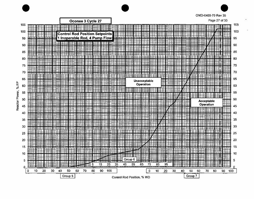
ONEI-0400-70 Rev 35
Oconee 3 Cycle 27 Page 27 of 33105 1105
CoHrrl Rod Position SetpoinItsConeral Rod, 4 Pum Fo 95
90 9
85 85
80 80
75 75
70 70
65 Unacceptable 6.6 Operation 60
60II-55 55
050Acceptable 5
o Operation 45w45 4
C+
40 40
35 35
30 30
25 25
20 20
15 15
90 "10
5 5====G5 Go 7' H H5 55 65 H5 85
80 ...... 80I0 Ill lil Ill I0 50 ll 0 10 90101 It 1 20 13011 10 l 160 m0l 80I 1 0
I I
Control Rod Position, % WD I Group 7 1
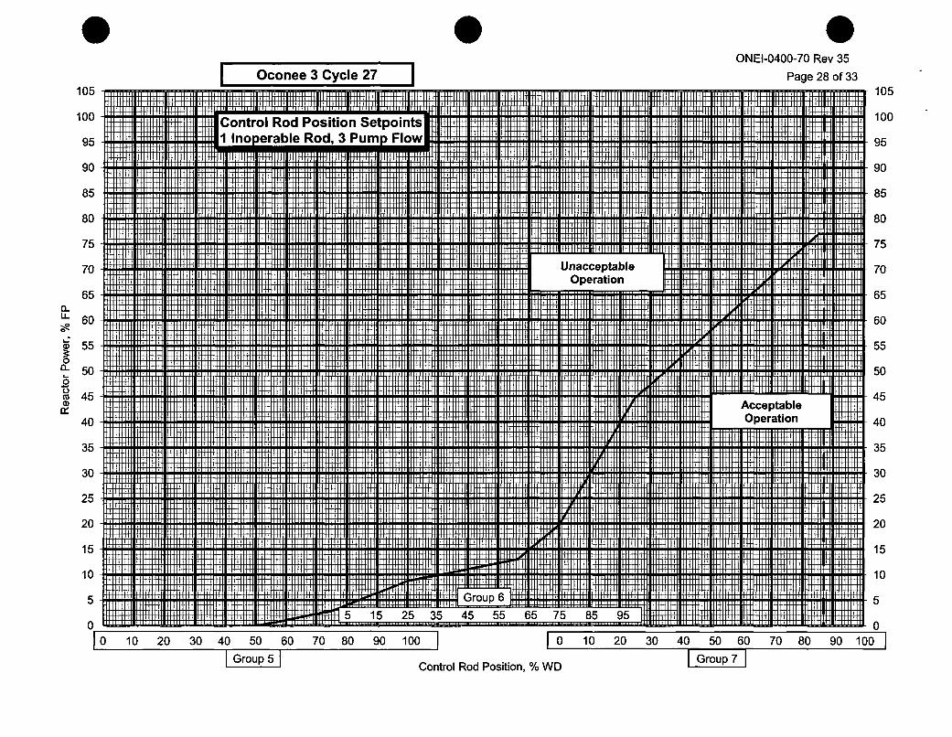
ONEI-0400-70 Rev 35
I Page 28 of 33I Oconee 3 Cycle 27105
100 Control Rod Position Setpoints
95 1 Inoperable Rod, 3 Pump Flow
90 I
i105
100
95
90;I
(LLL
L.2O.Cu-
a)
85
80
75
70
65
60
55
50
45
40
35
30
25
UnacceptableOperation
II
M
85
80
75
70
65
60
55
50
45
40
35
4 AcceptableOperation 1
+H+4 Th LIThEThIW ii
120
15
10
30
25
20
15
10
5i5
2
Gop6
H I15 25 35 45 55 65 75 85 950-I ... ........ .L .. ............ .. ............ ...... 010 10 20 30 40 50 60 70 80 90 100 I0 10 20 30 40 50 60 70 80 90 100j
I Group 5 SGroup 7Control Rod Position, % WD
ONEI-0400-70 Rev 35Page 29 of 33
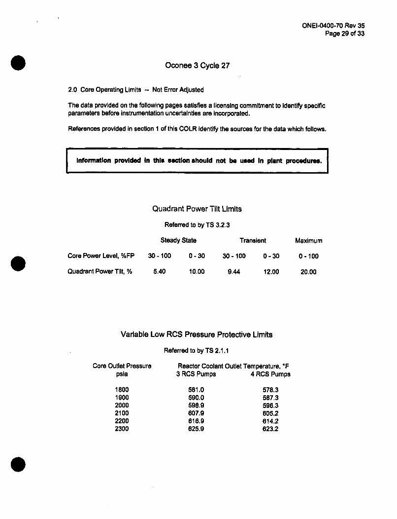
Oconee 3 Cycle 27
2.0 Core Operating Limits -- Not Error Adjusted
The data provided on the following pages satisfies a licensing commitment to Identify specificparameters before instrumentation uncertainties are Incorporated.
References provided in section 1 of this COLR Identify the sources for the data which follows.
Information provided in this section should not be used In plant procedures.
Core Power Level,
Quadrant Power Ti
Core Outip
Ii1121222
%FP 3C
lit, %
Quadrant Power Tilt Limits
Referred to by TS 3.2.3
Steady State T
)-100 0-30 30-10
5.40 10.00 9.44
ransient
) 0-30
12.00
Maximum
0-100
20.00
Variable Low RCS Pressure Protective Limits
Referred to by TS 2.1.1
et Pressure Reactor Coolant Outlet Temperature, OFsla 3 RCS Pumps 4 RCS Pumps
800 581.0 578.3900 590.0 587.3000 598.9 596.3100 607.9 605.2200 616.9 614.2300 625.9 623.2
ONEI-0400-70 Rev 35Page 30 of 33
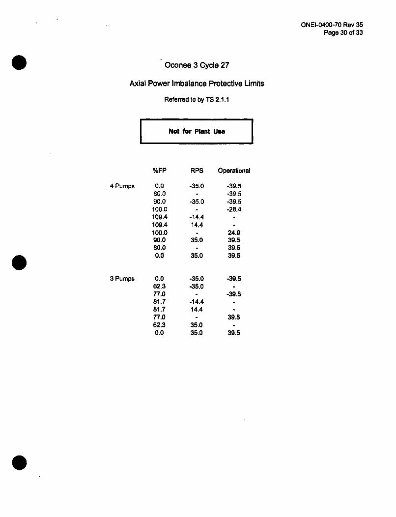
Oconee 3 Cycle 27
Axial Power Imbalance Protective Limits
Referred to by TS 2.1.1
I Not for Plant U".
4 Pumps
3 Pumps
%FP
0.080.090.0100.0109.4109.4100.090.080.00.0
0.062.377.081.781.777.062.30.0
RPS Operational
-35.0
-35.0
-14.414.4
35.0
35.0
-35.0-35.0
-14.414.4
35.035.0
-39.5-39.5-39.5-28.4
24.939.539.539.5
-39.5
-39.5
39.5
39.5
ONEI-0400-70 Rev 35Page 31 of 33
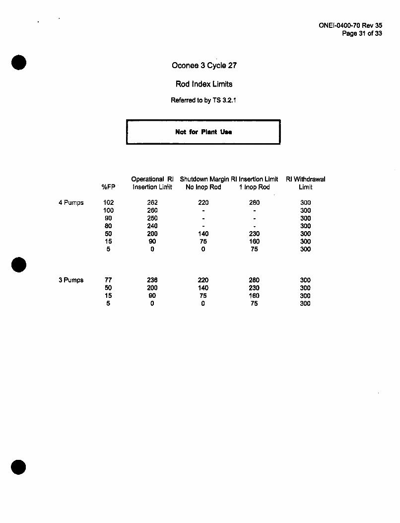
Oconee 3 Cycle 27
Rod Index Limits
Referred to by TS 3.2.1
I Not for Plant Use I
Operational RI%FP Insertion Limit
Shutdown Margin RI Insertion LimitNo Inop Rod 1 Inop Rod
4 Pumps
3 Pumps
102100908050155
7750155
262260250240200900
23e200900
220
140750
220140750
280
23016075
28023016075
RI WithdrawalLimit
300300300300300300300
300300300300
ONEI-0400-70 Rev 35Page 32 of 33
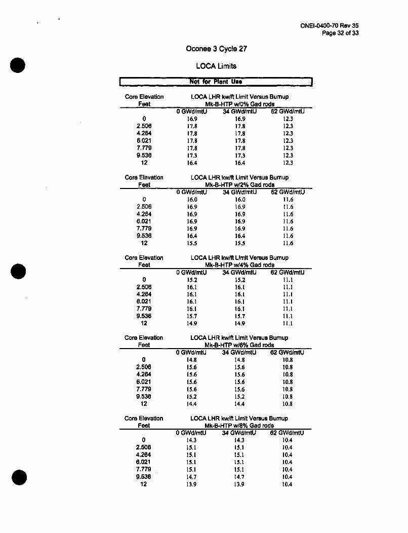
Oconee 3 Cycle 27
LOCA Limits
Not for Plant Use
Core Elevation LOCA LHR kw/ft Limit Versus BumupFeet Mk-B-HTP w10% Gad rods
0 GWd/mtU 34 GWd/mtU 62 GWdImtU0 16.9 16.9 12.3
2.506 17.8 17.8 12.34.264 17.8 17.8 12.36.021 17.8 17.8 12.37.779 17.8 17.8 12.39.538 17.3 17.3 12.3
12 16.4 16.4 12.3
Core Elevation LOCA LHR kw/ft Limit Versus BumupFeet Mk-B-HTP w12% Gad rods
02.5064.2646.0217.7799.536
12
0 GWd/mtU 34 GWd/mtU 62 GWd/mtU16.0 16.0 11.616.9 16.9 11.616.9 16.9 11.616.9 16.9 11.616.9 16.9 11.616.4 16.4 11.615.5 15.5 11.6
Core Elevation LOCA LHR kw/ft Limit Versus BumupFeet Mk-B-HTP w/4% Gad rods
0 GWd/mtU 34 GWd/mtU 62 GWd/mtU0 15.2 15.2 11.1
2.506 16.1 16.1 11.14.264 16.1 16.1 11.16.021 16.1 16.1 11.17.779 16.1 16.1 11.19.536 15.7 15.7 11.1
12 14.9 14.9 11.1
Core Elevation LOCA LHR kw/ft Limit Versus BumupFeet Mk-B-HTP w/6% Gad rods
0 GWd/mtU 34 GWd/mtU 62 GWd/mtU0 14.8 14.8 10.8
2.506 15.6 15.6 10.84.264 15.6 15.6 10.86.021 15.6 15.6 10.87.779 15.6 15.6 10.89.536 15.2 15.2 10.8
12 14.4 14.4 10.8
Core Elevation LOCA LHR kw/ft Limit Versus BumupFeet Mk-B-HTP w/8% Gad rods
02.5064.2646.0217.7799.536
12
0 GWd/mtU 34 GWd/mtU 62 GWd/mtU14.3 14.3 10.415.1 15.1 10.415.1 15.1 10.415.1 15.1 10.415.1 15.1 10.414.7 14.7 10.413.9 13.9 10.4

ONEI-0400-70 Rev 35Page 33 of 33
Oconee 3 Cycle 27
Not for Pint UseInstrument uncertainties are not Included In the values shown.
4 RCP Operation - Loop Averae Temp., OF 3 RCP Operation - Loop Average Temp., TFATcold, TF Tayj (Analytical) Tavg (Analytical)
O.O <_35_.O < 81.U0.1 <581.0 <581.00.2 <581.1 <581.00.3 <581.1 <581.10.4 <581.2 <581.10.5 <581.2 <581.10.6 <581.2 <581.10.1 <581.3 <581.20.8 <581.3 <581.20.9 <581.3 <581.21. <581.4 <581.21.1 <581.4 <581.21.2 <581.5 <581.31.3 <581.5 <581.31.4 <581.5 <581.31.5 <581.6 <581.31.6 <581.6 -<581.41.7 <581.6 <581.41.8 <581.7 <581.4
<581.7 <581.42.0 <581.8 <581.42.1 <581.8 <581.52.2 <581.8 <581.52.3 <581.9 <581.52.4 <581.9 <581.5
<582.0 <581.62.6 <582.0 <581.62.7 <582.0 <581.62.8 <582.1 <581.62.9 <582.1 <581.63.0 <582.1 <581.73.1 <582.2 <581.73.2 <582.2 <581.7
3<582.3 <581.73.4 <582.3 <581.73.5 <582.3 <581.83.6 <582.4 <581.83.7 <582.4 <581.83.8 <582.4 <581.83.9 <582.5 <581.94.0 <582.5 <581.94.0 <582.6 <581.94.2 <582.6 <581.94.2 <582.6 <581.94.4 <582.7 <582.04.5 <582.7 <582.04.6 <582.7 <582.04.7 <582.8 <592.0
4.8 <582.8 <582.14.9 <582.9 <582.15.0 <582.9 <582.1