Embed Size (px)
Citation preview

OCTOPUS 300 Instructions for Use HAAG-STREIT 1500.1802144.02110
Tradition and Innovation
HAAG-STREIT AG, Switzerland, Phone: (+41-31) 978 0111, Fax: (+41-31) 978 0282, [email protected] HAAG-STREIT DEUTSCHLAND GmbH, Germany, Phone: (+49-4103) 709 02, Fax: (+49-4103) 709 370, [email protected] HAAG-STREIT FRANCE, France, Phone (+33-4) 5009 0033, Fax (+33-4) 5009 7190, [email protected] HAAG-STREIT UK, United Kingdom, Phone (+44-1279) 414969, Fax (+44-1279) 635232, [email protected] HAAG-STREIT USA, INC., USA, Phone: (+1-513) 336 6858, Fax: (+1-513) 336 7828, [email protected]
INSTRUCTIONS FOR USE Perimeter
OCTOPUS® 300 1500.1802144.02110 11. Edition / 2014-07
Tradition and Innovation
Page 2 / 56 OCTOPUS 300 Instructions for Use 1500.1802144.02110
INTRODUCTION We thank you for choosing a HAAG-STREIT appliance. Provided you comply carefully with the regulations in these instructions for use, we can guarantee the reliable and unproblematic use of our product. PURPOSE OF USE The Octopus 300 perimeter is designed for the examination, analysis and documentation of the field of sight, especially the light difference sensitivity and other functions of the human eye. GENERAL INFORMATION
WARNING! For perimetry no contraindications are known. Therefore there is no need for related measures.
WARNING! Read the instructions for use carefully before commissioning the Octopus 300. They contain important information concerning the safety of the user and patient.
NOTE! Federal law restricts this device to sale by or on the order of a physician or licensed practitioner.

Tradition and Innovation
OCTOPUS 300 Instruction for Use 1500.1802144.02110 Page 3 / 56
CONTENTS INTRODUCTION .....................................................................................................................................................................................2
PURPOSE OF USE .................................................................................................................................................................................2
GENERAL INFORMATION .....................................................................................................................................................................2 1 SAFETY ..........................................................................................................................................................................................6
1.1 Areas of application of the device ..........................................................................................................................................6 1.1.1 Patient population ..........................................................................................................................................................6
1.2 Ambient conditions .................................................................................................................................................................6 1.3 Shipment and unpacking ........................................................................................................................................................6 1.4 Installation warnings ...............................................................................................................................................................6 1.5 Operation and environment ....................................................................................................................................................7 1.6 Disinfection .............................................................................................................................................................................7 1.7 Warranty and product liability .................................................................................................................................................8 1.8 Symbols .................................................................................................................................................................................8
2 THE INSTRUMENT ......................................................................................................................................................................10 2.1 Perimeter Octopus 300 ........................................................................................................................................................10
2.1.1 Optical Unit ..................................................................................................................................................................11 2.1.2 Headrest ......................................................................................................................................................................11 2.1.3 Trial Lens holder ..........................................................................................................................................................11 2.1.4 Housing .......................................................................................................................................................................11 2.1.5 Fuses ...........................................................................................................................................................................11 2.1.6 Operating Unit .............................................................................................................................................................11 2.1.7 Patient Response Button .............................................................................................................................................12 2.1.8 External Connections ..................................................................................................................................................12 2.1.9 Light Sources ..............................................................................................................................................................12 2.1.10 Light Intensities ...........................................................................................................................................................12 2.1.11 Stimulus .......................................................................................................................................................................12 2.1.12 Fixation Monitoring ......................................................................................................................................................12 2.1.13 Examination Data ........................................................................................................................................................12
2.2 Instrument Transportation ....................................................................................................................................................12 2.3 Installation ............................................................................................................................................................................12
2.3.1 Instrument Table .........................................................................................................................................................12 2.3.2 Octopus 300 ................................................................................................................................................................12
3 OPERATION.................................................................................................................................................................................14 3.1 Switch on the device ............................................................................................................................................................14 3.2 Switch on the device ............................................................................................................................................................14 3.3 General functions .................................................................................................................................................................14
4 CONFIGURATION, SETUP..........................................................................................................................................................16 4.1 General Basic Settings .........................................................................................................................................................16 4.2 Presetting for Preparing an Examination .............................................................................................................................17 4.3 Defining the Variants of the Standard Examination Programs .............................................................................................18 4.4 Selecting the Perimetry Method ...........................................................................................................................................19 4.5 Defining user-defined Tests .................................................................................................................................................20 4.6 Settings for External Connections ........................................................................................................................................23 4.7 Ethernet Interface Settings ...................................................................................................................................................24 4.8 Settings for Data Communications .......................................................................................................................................25 4.9 Service Functions .................................................................................................................................................................25
5 PERFORMING AN EXAMINATION .............................................................................................................................................26 5.1 Instructing the Patient ..........................................................................................................................................................26 5.2 Trial Lenses ..........................................................................................................................................................................26 5.3 Situating the Patient .............................................................................................................................................................26 5.4 Preparing an Examination (Standard Program) ...................................................................................................................27 5.5 Preparing an Examination (CT Program) .............................................................................................................................29 5.6 Patient File ...........................................................................................................................................................................29 5.7 Information ...........................................................................................................................................................................30

Tradition and Innovation
Page 4 / 56 OCTOPUS 300 Instructions for Use 1500.1802144.02110
6 MONITORING AN EXAMINATION ..............................................................................................................................................31 6.1 Fine Positioning, Focusing ...................................................................................................................................................31 6.2 Command Buttons, Examination Progress ..........................................................................................................................31 6.3 Examination Information ......................................................................................................................................................32 6.4 Parameter Changing ............................................................................................................................................................32 6.5 Continuing an interrupted Examination ................................................................................................................................33
7 ANALYSIS OF EXAMINATION RESULTS ..................................................................................................................................34 7.1 Examination File ...................................................................................................................................................................34 7.2 Displaying the Results ..........................................................................................................................................................35 7.3 Printing the Results ..............................................................................................................................................................35 7.4 Transmitting the Results ......................................................................................................................................................37
7.4.1 Preparation ..................................................................................................................................................................37 7.5 Deleting Results ...................................................................................................................................................................37 7.6 Changing Patient Data .........................................................................................................................................................38
8 AUXILIARY FUNCTIONS.............................................................................................................................................................40 8.1 Releasing Program Options .................................................................................................................................................40
8.1.1 Procedure ....................................................................................................................................................................40 8.1.2 Entering the Dongle Code ...........................................................................................................................................41
8.2 The Results of Code Mistakes .............................................................................................................................................41 8.3 Instrument Information .........................................................................................................................................................41 8.4 Touch Screen Calibration .....................................................................................................................................................41
9 SYSTEM MESSAGES / ERRORS ...............................................................................................................................................43 9.1 Messages .............................................................................................................................................................................43 9.2 Errors ...................................................................................................................................................................................43
10 SOFTWARE UPDATES ...............................................................................................................................................................46 11 TECHNICAL DATA ......................................................................................................................................................................47
11.1 OCTOPUS 300 ....................................................................................................................................................................47 11.2 Infrared Illumination ..............................................................................................................................................................47
12 CARE AND MAINTENANCE .......................................................................................................................................................48 12.1 Maintenance .........................................................................................................................................................................48 12.2 Cleaning ...............................................................................................................................................................................48
12.2.1 Applied parts ...............................................................................................................................................................48 12.2.2 Ocular ..........................................................................................................................................................................48
12.3 Light Sources .......................................................................................................................................................................48
A. APPENDIX....................................................................................................................................................................................49 A.1 Accessories /spare parts ......................................................................................................................................................49 A2. Legal regulations ..................................................................................................................................................................49 A3. Classification ........................................................................................................................................................................49 A4. Disposal ...............................................................................................................................................................................49 A5. Standards .............................................................................................................................................................................49 A5. RoHS China .........................................................................................................................................................................50
B. INFORMATION AND MANUFACTURER’S DECLARATION CONCERNING ELECTROMAGNETIC COMPATIBILITY (EMC) 51
B.1 General ................................................................................................................................................................................51 Table 1: Emission ..............................................................................................................................................................................51 Table 2: Immunity (all devices)..........................................................................................................................................................52 Table 3: Immunity (not life-support device) .......................................................................................................................................52 Table 4: Recommended separation distances (not life-support equipment) .....................................................................................53

Tradition and Innovation
OCTOPUS 300 Instruction for Use 1500.1802144.02110 Page 5 / 56
Change index Rev 11 Generally changed “FORBIDDEN!” to “DANGER!”, p2 chapter General Information, paragraph: Note!
Federal law restricts this device to sale by or on the order of a physician or licensed practitioner., p6 chapter 1.4 changed paragraph: “DANGER! Failure to comply with these instructions may result in material damage or pose a danger to patients or users.”, p8 chapter 1.7. changed completely
PhR
Rev 10 Addendum according to 3rd. Edition EN 60601-1 PGl Rev 9 Added EMC-supplement (page 49-51) EF Rev 8 Removal of CE-mark OB Rev 7 Octopus 311 is renamed to Octopus 300. Octopus 301 is discontinued MM Rev 6 Attention note to print configuration prior to perform an update (page 16)
Environment note according to CE guideline (page 50) MM
Tradition and Innovation
Page 6 / 56 OCTOPUS 300 Instructions for Use 1500.1802144.02110
1 SAFETY
DANGER! Failure to comply with these instructions may result in material damage or pose a danger to patients or users.
WARNING! These warnings must absolutely be complied with to guarantee safe operation of the device and to avoid any danger to users and to patients.
NOTE! Important information: please read carefully.
1.1 Areas of application of the device The users are ophthalmologists, optometrists, opticians, orthoptists or other trained specialists. The examination is performed in darkened examination rooms. 1.1.1 Patient population The patient is capable of sitting up straight and keeping his head still. He is physically and mentally able to cooperate well and is mentally competent of following the examination. Patients must be at least 6 years old. 1.2 Ambient conditions See chapter 11 Technical Data. 1.3 Shipment and unpacking
• Before you unpack the appliance, check whether the packaging shows traces of incorrect handling or damage. If this is the case, notify the transport company that has delivered the goods to you. Unpack the equipment together with a representative of the transport company. Make a report of any damaged parts. This report must be signed by you and by the representative of the transport company.
• Leave the device in the packaging for a few hours before unpacking it (condensation). • Check the appliance for damage after it is unpacked. Return defective appliances in the appropriate packaging. • Store packaging material carefully, so that it can be used for possible returns or when moving. 1.4 Installation warnings
DANGER! • Never use the device in potentially explosive environments where volatile solvents (alcohol, benzine, etc.) and
combustible anesthetics are employed.
WARNING! • Installation, repairs and modifications may only be performed by trained specialists. • If a third-party device is connected, this must be done in compliance with the IEC/EN 60601-1 standard.
WARNING! • A printer used with the device must be connected to the mains via isolation transformer.
NOTE! • The instrument is to be installed on the height-adjustable table and employed in a dimly lit room in a medical area. • The use of accessories other than those listed may result in higher emissions or lower interference immunity of the
Octopus 300. • The software must be installed by trained personnel.
Tradition and Innovation
OCTOPUS 300 Instruction for Use 1500.1802144.02110 Page 7 / 56
1.5 Operation and environment
WARNING! • To avoid the risk of suffering an electric shock, this device can only be connected up to the mains with a protective
earth. • The plug, cable and the protective earth of the socket must function perfectly. • Make sure that the appliance is connected only to power supplies as defined on the type plate. The appliance must
be disconnected from the mains by pulling out the plug before any maintenance and cleaning work is performed.
WARNING! • The doctor or the operator is obliged to inform the patient about the safety instructions concerning him and to
ensure that these instructions are complied with. • The examination of the patient, the use of the device and the interpretation of the results may only be conducted by
trained and experienced personnel. • All users must be appropriately trained and familiarized with the contents of the instructions for use, especially in
regard to the safety information contained therein.
WARNING! • Do not use a defective device or a device that displayed an error message. • Call service department or your distributor and wait for repair.
WARNING! • Please note that the light emission of the two IR-LEDs built into the correction lens holder is not visible for the
human eye. • Wavelength at peak emission = 880nm; spectral bandwidth at 50% of Imax = 80nm.
NOTE! • The Octopus 300 may only be operated by qualified and trained personnel. The owner is responsible for their
training. • The present appliance may be used only for the purpose described in these instructions for use.
NOTE! • Keep these instructions for use in a place where they are accessible at all times to those working with the device.
Warranty claims can only be made if the instructions in these instructions for use are complied with. • Always remove the dust cover before switching the appliance on. The device may otherwise become damaged due
to overheating. Similarly, make sure that the appliance is switched off before it is covered. • Only original spare parts and original accessories may be used for repairs. The use of accessories other than those
listed may result in higher emissions or lower interference immunity of the Octopus 300. • Turn the system off if it will not be used for an extended period of time.
1.6 Disinfection
NOTE! • For information on cleaning and disinfection, please refer to the 'Maintenance' section.
Tradition and Innovation
Page 8 / 56 OCTOPUS 300 Instructions for Use 1500.1802144.02110
1.7 Warranty and product liability
• Haag-Streit products must be used only for the purposes and in the manner described in the documents distributed with the product.
• The product must be treated as described in the 'Safety' chapter. Improper handling can damage the product. This would void all guarantee claims.
• Continued use of a product damaged by incorrect handling may lead to personal injury. In such a case, the manufacturer will not accept any liability.
• Haag-Streit does not grant any warranties, either expressed or implied, including implied warranties of merchantability or fitness for a particular use.
• Haag-Streit expressly disclaims liability for incidental or consequential damage resulting from the use of the product. • This product is covered by a limited warranty granted by your seller. • For USA only: This product is covered by a limited warranty, which may be reviewed at www.haag-streit-usa.com.
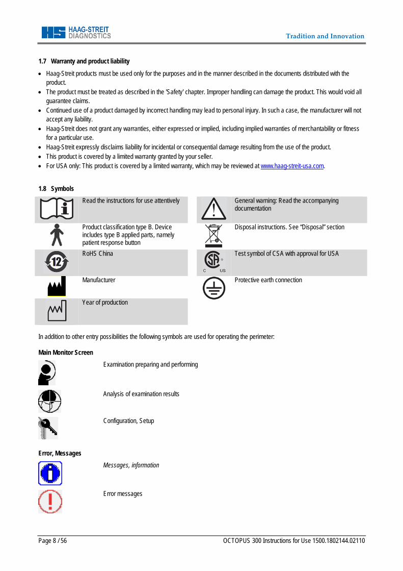
1.8 Symbols
Read the instructions for use attentively
General warning: Read the accompanying documentation
Product classification type B. Device includes type B applied parts, namely patient response button
Disposal instructions. See “Disposal” section
RoHS China
Test symbol of CSA with approval for USA
Manufacturer Protective earth connection
Year of production
In addition to other entry possibilities the following symbols are used for operating the perimeter:
Main Monitor Screen
Examination preparing and performing
Analysis of examination results
Configuration, Setup
Error, Messages
Messages, information
Error messages
Tradition and Innovation
OCTOPUS 300 Instruction for Use 1500.1802144.02110 Page 9 / 56
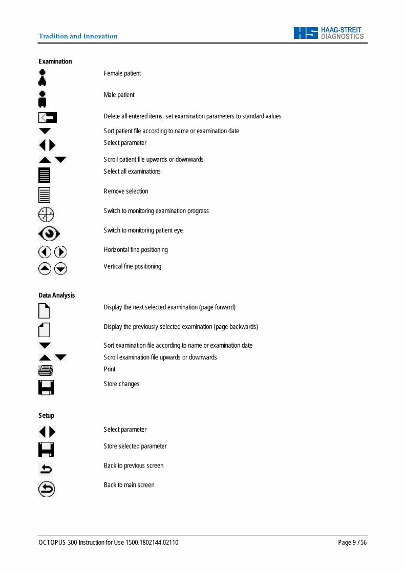
Examination
Female patient
Male patient
Delete all entered items, set examination parameters to standard values
Sort patient file according to name or examination date
Select parameter
Scroll patient file upwards or downwards
Select all examinations
Remove selection
Switch to monitoring examination progress
Switch to monitoring patient eye
Horizontal fine positioning
Vertical fine positioning
Data Analysis
Display the next selected examination (page forward)
Display the previously selected examination (page backwards)
Sort examination file according to name or examination date
Scroll examination file upwards or downwards
Store changes
Setup
Select parameter
Store selected parameter
Back to previous screen
Back to main screen
Tradition and Innovation
Page 10 / 56 OCTOPUS 300 Instructions for Use 1500.1802144.02110
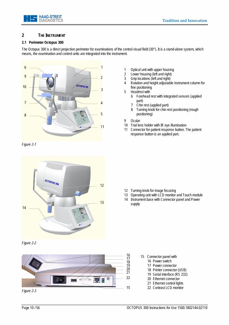
2 THE INSTRUMENT 2.1 Perimeter Octopus 300 The Octopus 300 is a direct projection perimeter for examinations of the central visual field (30°). It is a stand-alone system, which means, the examination and control units are integrated into the instrument.
Figure 2-1
1 Optical unit with upper housing 2 Lower housing (left and right) 3 Grip locations (left and right) 4 Rotation and height adjustable instrument column for
fine positioning 5 Headrest with
6 Forehead rest with integrated sensors (applied part)
7 Chin rest (applied part) 8 Turning knob for chin rest positioning (rough
positioning)
9 Ocular 10 Trial lens holder with IR eye illumination 11 Connector for patient response button. The patient
response button is an applied part.
Figure 2-2
12 Turning knob for image focusing 13 Operating unit with LCD monitor and Touch module 14 Instrument base with Connector panel and Power
supply
Figure 2-3
15 Connector panel with 16 Power switch 17 Power connector 18 Printer connector (USB) 19 Serial interface (RS 232) 20 Ethernet connector 21 Ethernet control lights 22 Contrast LCD monitor
1
4
8
3
6
7
5
2
10
9
12
14 13
11
16
19
17
21 20
18
22
15
Tradition and Innovation
OCTOPUS 300 Instruction for Use 1500.1802144.02110 Page 11 / 56
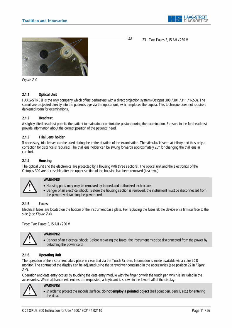
Figure 2-4
23 Two Fuses 3,15 AH / 250 V
2.1.1 Optical Unit HAAG-STREIT is the only company which offers perimeters with a direct projection system (Octopus 300 / 301 / 311 / 1-2-3). The stimuli are projected directly into the patient's eye via the optical unit, which replaces the cupola. This technique does not require a darkened room for examinations. 2.1.2 Headrest A slightly tilted headrest permits the patient to maintain a comfortable posture during the examination. Sensors in the forehead rest provide information about the correct position of the patient's head. 2.1.3 Trial Lens holder If necessary, trial lenses can be used during the entire duration of the examination. The stimulus is seen at infinity and thus only a correction for distance is required. The trial lens holder can be swung forwards approximately 25° for changing the trial lens in comfort. 2.1.4 Housing The optical unit and the electronics are protected by a housing with three sections. The optical unit and the electronics of the Octopus 300 are accessible after the upper section of the housing has been removed (4 screws).
WARNING! • Housing parts may only be removed by trained and authorized technicians. • Danger of an electrical shock! Before the housing section is removed, the instrument must be disconnected from
the power by detaching the power cord. 2.1.5 Fuses Electrical fuses are located on the bottom of the instrument base plate. For replacing the fuses tilt the device on a firm surface to the side (see Figure 2-4). Type: Two Fuses 3,15 AH / 250 V
WARNING! • Danger of an electrical shock! Before replacing the fuses, the instrument must be disconnected from the power by
detaching the power cord. 2.1.6 Operating Unit The operation of the instrument takes place in clear text via the Touch Screen. Information is made available via a color LCD monitor. The contrast of the display can be adjusted using the screwdriver contained in the accessories (see position 22 in Figure 2-4). Operation and data entry occurs by touching the data entry module with the finger or with the touch pen which is included in the accessories. When alphanumeric entries are requested, a keyboard is shown in the lower half of the display.
WARNING! • In order to protect the module surface, do not employ a pointed object (ball point pen, pencil, etc.) for entering
the data.
23
Tradition and Innovation
Page 12 / 56 OCTOPUS 300 Instructions for Use 1500.1802144.02110
2.1.7 Patient Response Button The patient response button is connected on the underside of the headrest holder (RJ11 connector). 2.1.8 External Connections Connection possibilities for a printer (USB interface) and for a PC (RS 232 and Ethernet interface) are provided on the connector panel. All connections are electrically isolated and have a dielectric strength of 4 kV according to EN 60601-1. 2.1.9 Light Sources LEDs are built in for background illumination, fixation targets and stimulus. LEDs produce no waste heat and thus no active cooling is required. 2.1.10 Light Intensities The light intensity of the stimulus and background are measured with independent photo sensors and are calibrated to their preset reference values every time the perimeter is switched on. 2.1.11 Stimulus The duration and brightness of the stimuli are controlled electronically. A mechanical shutter and optical attenuation elements are unnecessary. 2.1.12 Fixation Monitoring The eye of the patient being examined is illuminated with IR LEDs, recorded using a CCD camera and displayed on the LCD monitor. The built in automatic patient monitoring guarantees the reliability of the examination results. The fine positioning of the examined eye takes place via a motorized fine adjustment of the optical unit. 2.1.13 Examination Data The built in data storage offers room for 48 examinations. Examination results can be shown on the built in LCD monitor, issued on the printer connected to the USB interface and / or transmitted over the serial interface to a PC. 2.2 Instrument Transportation Transport the instrument over large distances in the original packing. For short distances the instrument can be lifted using the two lower housing sides (see Figure 2-1) Two ribbed grips are provided on the left and right sides which prevent from slipping sideways.
DANGER! • Do not use the forehead rest of the perimeter as a carrying handle. This plastic part is not adequate for the weight
and can be thus broken. 2.3 Installation 2.3.1 Instrument Table The instrument table is delivered in a separate package. Utilize the instructions included with the table to put the table together and take care to select the correct voltage before connecting the power cord. 2.3.2 Octopus 300 Handle the instrument using both lower housing halves to lift it out of the packing. Two ribbed grips hinder sideways slipping.
DANGER! • Do not use the forehead rest of the perimeter as a carrying handle. This plastic part is not adequate for the weight
and can be thus broken. Since the Octopus 300 works without a cupola, a fully darkened room is not required. In order, though, to make the examination conditions pleasant for the patient and for obtaining reliable results, the instrument is to be placed in the room so that no direct light falls on the instrument or the patient. The positioning between the patient and the operator or the operating panel can be so chosen that the room conditions are optimally used.
Tradition and Innovation
OCTOPUS 300 Instruction for Use 1500.1802144.02110 Page 13 / 56
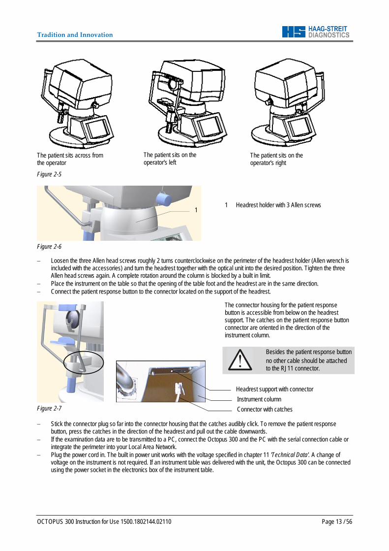
The patient sits across from the operator
Figure 2-5
The patient sits on the operator's left
The patient sits on the operator's right
Figure 2-6
1 Headrest holder with 3 Allen screws
− Loosen the three Allen head screws roughly 2 turns counterclockwise on the perimeter of the headrest holder (Allen wrench is
included with the accessories) and turn the headrest together with the optical unit into the desired position. Tighten the three Allen head screws again. A complete rotation around the column is blocked by a built in limit.
− Place the instrument on the table so that the opening of the table foot and the headrest are in the same direction. − Connect the patient response button to the connector located on the support of the headrest.
Figure 2-7
The connector housing for the patient response button is accessible from below on the headrest support. The catches on the patient response button connector are oriented in the direction of the instrument column.
Besides the patient response button no other cable should be attached to the RJ11 connector.
− Stick the connector plug so far into the connector housing that the catches audibly click. To remove the patient response
button, press the catches in the direction of the headrest and pull out the cable downwards. − If the examination data are to be transmitted to a PC, connect the Octopus 300 and the PC with the serial connection cable or
integrate the perimeter into your Local Area Network. − Plug the power cord in. The built in power unit works with the voltage specified in chapter 11 'Technical Data'. A change of
voltage on the instrument is not required. If an instrument table was delivered with the unit, the Octopus 300 can be connected using the power socket in the electronics box of the instrument table.
Headrest support with connector Instrument column Connector with catches
1
Tradition and Innovation
Page 14 / 56 OCTOPUS 300 Instructions for Use 1500.1802144.02110
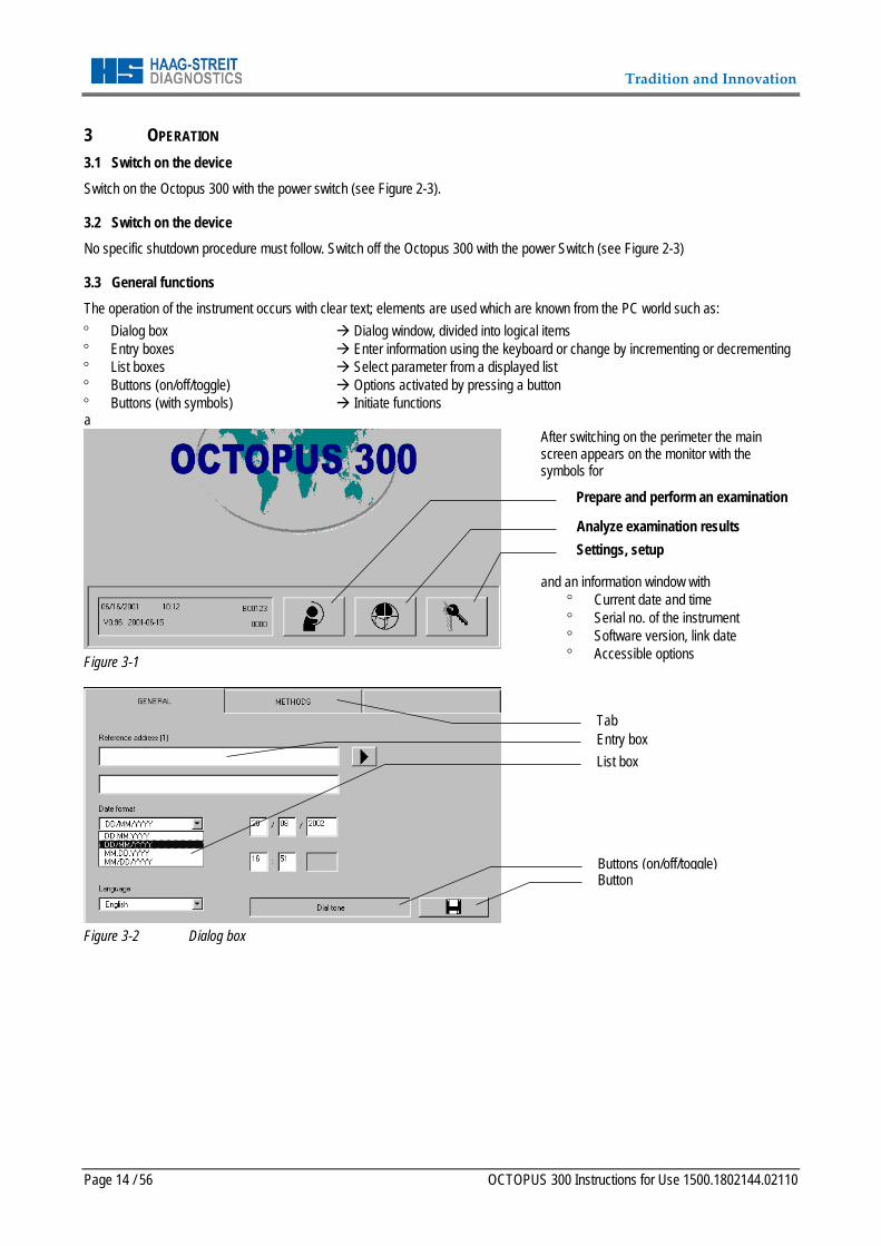
3 OPERATION 3.1 Switch on the device Switch on the Octopus 300 with the power switch (see Figure 2-3). 3.2 Switch on the device No specific shutdown procedure must follow. Switch off the Octopus 300 with the power Switch (see Figure 2-3) 3.3 General functions The operation of the instrument occurs with clear text; elements are used which are known from the PC world such as: ° Dialog box Dialog window, divided into logical items ° Entry boxes Enter information using the keyboard or change by incrementing or decrementing ° List boxes Select parameter from a displayed list ° Buttons (on/off/toggle) Options activated by pressing a button ° Buttons (with symbols) Initiate functions a
Figure 3-1
After switching on the perimeter the main screen appears on the monitor with the symbols for
and an information window with
° Current date and time ° Serial no. of the instrument ° Software version, link date ° Accessible options
Figure 3-2 Dialog box
Settings, setup Analyze examination results
Prepare and perform an examination
Tab Entry box List box
Buttons (on/off/toggle) Button
Tradition and Innovation
OCTOPUS 300 Instruction for Use 1500.1802144.02110 Page 15 / 56
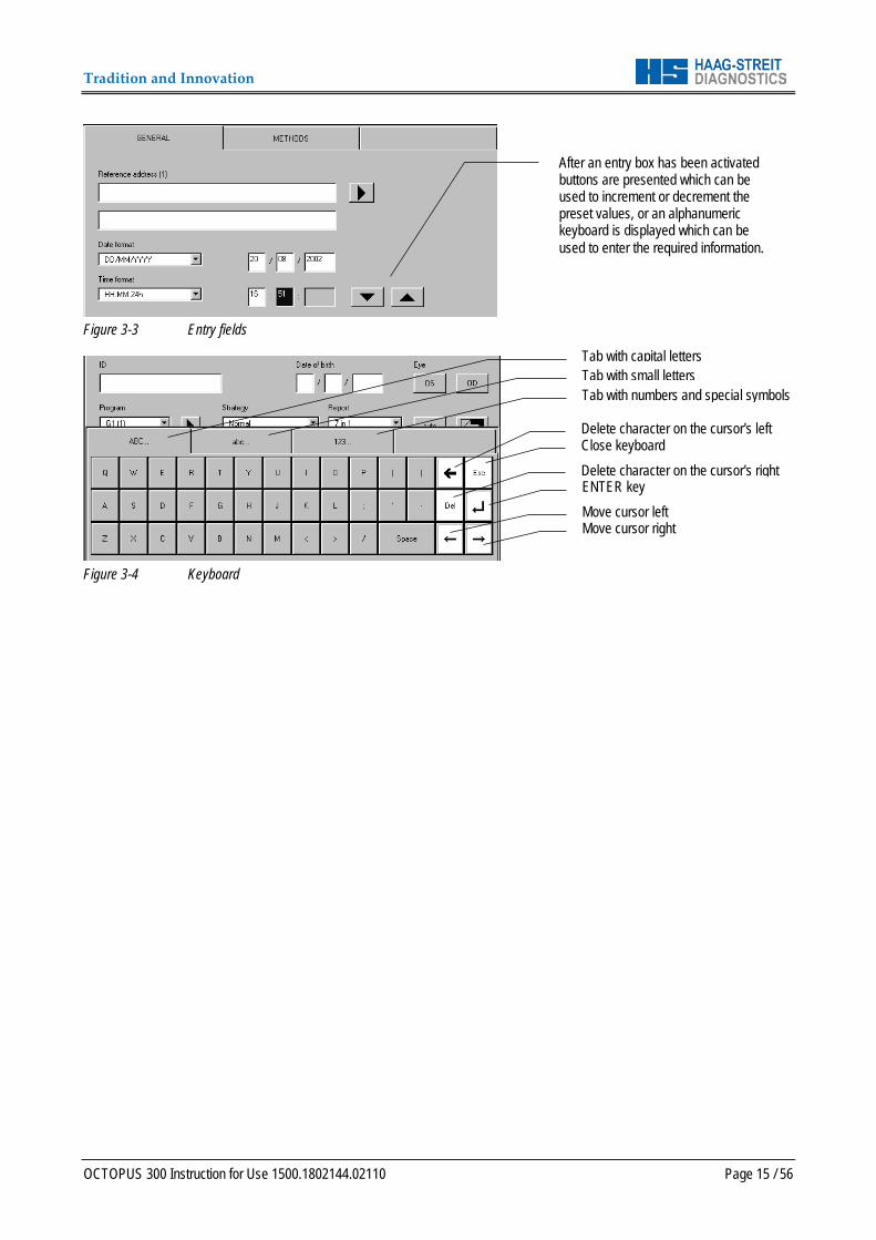
Figure 3-3 Entry fields
Figure 3-4 Keyboard
Tab with capital letters Tab with small letters Tab with numbers and special symbols
Delete character on the cursor's left Close keyboard Delete character on the cursor's right ENTER key Move cursor left Move cursor right
After an entry box has been activated buttons are presented which can be used to increment or decrement the preset values, or an alphanumeric keyboard is displayed which can be used to enter the required information.
Tradition and Innovation
Page 16 / 56 OCTOPUS 300 Instructions for Use 1500.1802144.02110
4 CONFIGURATION, SETUP In order to perform examinations with the Octopus 300 and analyze the results, only a few items have to be entered or manipulations made when configuration and setup has been correctly carried out. It will prove valuable to study the following chapter in order to work with the instrument efficiently.
Basically ° The options are selected which are shown in the window of a dialog box. ° A function is activated when the associated button is pressed. ° For alphanumeric information, a keyboard is displayed automatically or the values are changed by incrementing or
decrementing. ° Before the box is closed the selected changes must be stored.
4.1 General Basic Settings
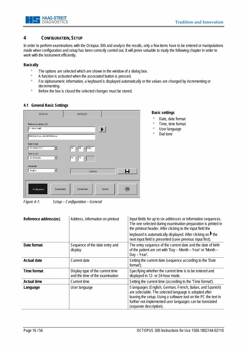
Figure 4-1: Setup – Configuration – General
Basic settings ° Date, date format ° Time, time format ° User language ° Dial tone
Reference address(es) Address, information on printout Input fields for up to six addresses or information sequences.
The one selected during examination preparation is printed in the printout header. After clicking to the input field the keyboard is automatically displayed. After clicking on the next input field is presented (save previous input first).
Date format Sequence of the date entry and display
The entry sequence of the current date and the date of birth of the patient are set with 'Day – Month – Year' or 'Month – Day – Year'.
Actual date Current date Setting the current date (sequence according to the 'Date format').
Time format Display type of the current time and the time of the examination
Specifying whether the current time is to be entered and displayed in 12- or 24-hour mode.
Actual time Current time Setting the current time (according to the 'Time format'). Language User language 5 languages (English, German, French, Italian, and Spanish)
are selectable. The selected language is adopted after leaving the setup. Using a software tool on the PC the text in further not implemented user languages can be translated (separate description).
Tradition and Innovation
OCTOPUS 300 Instruction for Use 1500.1802144.02110 Page 17 / 56
Dial tone Confirmation sound for keyed entries For activating or deactivating a sound as confirmation when a button is pressed.
Changes must be stored by pressing before leaving the dialog box. 4.2 Presetting for Preparing an Examination
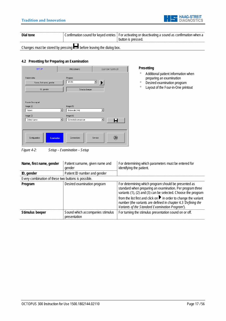
Figure 4-2: Setup – Examination – Setup
Presetting ° Additional patient information when
preparing an examination ° Desired examination program ° Layout of the Four-in-One printout
Name, first name, gender Patient surname, given name and
gender For determining which parameters must be entered for identifying the patient.
ID, gender Patient ID number and gender Every combination of these two buttons is possible. Program Desired examination program For determining which program should be presented as
standard when preparing an examination. Per program three variants (1), (2) and (3) can be selected. Choose the program from the list first and click on in order to change the variant number (the variants are defined in chapter 4.3 'Defining the Variants of the Standard Examination Program').
Stimulus beeper Sound which accompanies stimulus presentation
For turning the stimulus presentation sound on or off.
Tradition and Innovation
Page 18 / 56 OCTOPUS 300 Instructions for Use 1500.1802144.02110
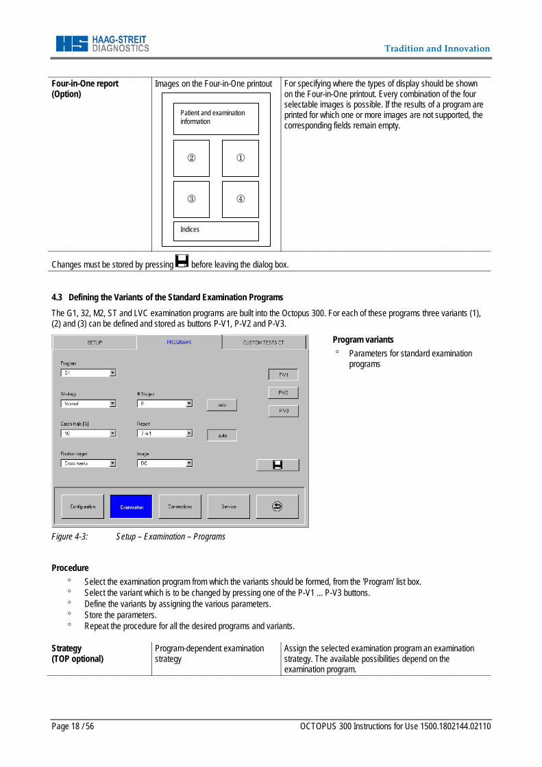
Four-in-One report (Option)
Images on the Four-in-One printout
For specifying where the types of display should be shown on the Four-in-One printout. Every combination of the four selectable images is possible. If the results of a program are printed for which one or more images are not supported, the corresponding fields remain empty.
Changes must be stored by pressing before leaving the dialog box. 4.3 Defining the Variants of the Standard Examination Programs The G1, 32, M2, ST and LVC examination programs are built into the Octopus 300. For each of these programs three variants (1), (2) and (3) can be defined and stored as buttons P-V1, P-V2 and P-V3.
Figure 4-3: Setup – Examination – Programs
Program variants ° Parameters for standard examination
programs
Procedure
° Select the examination program from which the variants should be formed, from the 'Program' list box. ° Select the variant which is to be changed by pressing one of the P-V1 ... P-V3 buttons. ° Define the variants by assigning the various parameters. ° Store the parameters. ° Repeat the procedure for all the desired programs and variants.
Strategy (TOP optional)
Program-dependent examination strategy
Assign the selected examination program an examination strategy. The available possibilities depend on the examination program.
Indices
Patient and examination information
Tradition and Innovation
OCTOPUS 300 Instruction for Use 1500.1802144.02110 Page 19 / 56
# Stages auto (# Stages)
Number of examination stages Specify the number of examination stages which should be gone through. If the 'auto' button on the side is pressed, the program will end once the stages have been gone through. If it is not pressed, the '# Stages' selection has no meaning.
Catch trials [%] Number of catch trials in [%] Set the number of catch trials as a percentage [%] which should be presented during the examination (same number of positive and negative catch trials).
Fixation target Fixation symbol Set the fixation target which is displayed for the patient during the examination. If the selected fixation target collides with a test location, another target is displayed during the corresponding stage.
Image Desired type of display Select the default display which is to be shown on the monitor. The possibilities depend on the selected examination program (see Table 9-1).
Report auto (Report)
Desired printout Select the default display which is to be printed. The possibilities depend on the selected examination program (see Table 9-1). If the 'auto' button at the side is pressed, the selected printout will be printed automatically at the end of the examination. If the button has not been pressed, the 'Report' selection has no meaning.
Store the definitions by pressing before leaving the dialog box or selecting a further variant. 4.4 Selecting the Perimetry Method
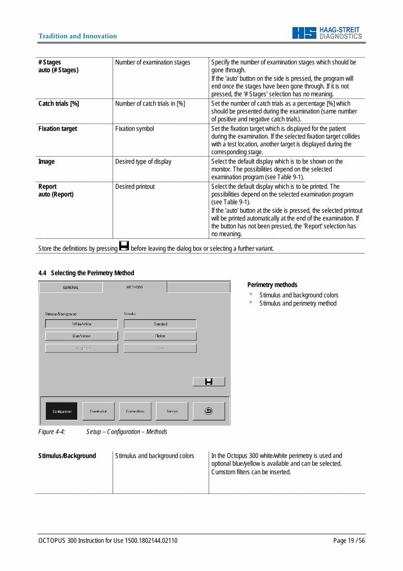
Figure 4-4: Setup – Configuration – Methods
Perimetry methods ° Stimulus and background colors ° Stimulus and perimetry method
Stimulus/Background Stimulus and background colors In the Octopus 300 white/white perimetry is used and
optional blue/yellow is available and can be selected. Cumstom filters can be inserted.
Tradition and Innovation
Page 20 / 56 OCTOPUS 300 Instructions for Use 1500.1802144.02110
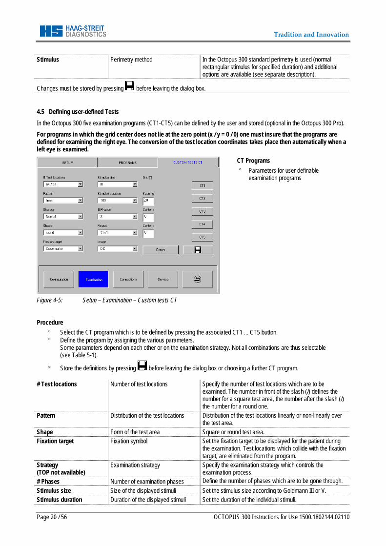
Stimulus Perimetry method In the Octopus 300 standard perimetry is used (normal rectangular stimulus for specified duration) and additional options are available (see separate description).
Changes must be stored by pressing before leaving the dialog box. 4.5 Defining user-defined Tests In the Octopus 300 five examination programs (CT1-CT5) can be defined by the user and stored (optional in the Octopus 300 Pro).
For programs in which the grid center does not lie at the zero point (x / y = 0 / 0) one must insure that the programs are defined for examining the right eye. The conversion of the test location coordinates takes place then automatically when a left eye is examined.
Figure 4-5: Setup – Examination – Custom tests CT
CT Programs ° Parameters for user definable
examination programs
Procedure
° Select the CT program which is to be defined by pressing the associated CT1 ... CT5 button. ° Define the program by assigning the various parameters.
Some parameters depend on each other or on the examination strategy. Not all combinations are thus selectable (see Table 5-1).
° Store the definitions by pressing before leaving the dialog box or choosing a further CT program.
# Test locations Number of test locations Specify the number of test locations which are to be examined. The number in front of the slash (/) defines the number for a square test area, the number after the slash (/) the number for a round one.
Pattern Distribution of the test locations Distribution of the test locations linearly or non-linearly over the test area.
Shape Form of the test area Square or round test area. Fixation target Fixation symbol Set the fixation target to be displayed for the patient during
the examination. Test locations which collide with the fixation target, are eliminated from the program.
Strategy (TOP not available)
Examination strategy Specify the examination strategy which controls the examination process.
# Phases Number of examination phases Define the number of phases which are to be gone through. Stimulus size Size of the displayed stimuli Set the stimulus size according to Goldmann III or V. Stimulus duration Duration of the displayed stimuli Set the duration of the individual stimuli.

Tradition and Innovation
OCTOPUS 300 Instruction for Use 1500.1802144.02110 Page 21 / 56
Report Desired printout Select the default image to be printed out. The possibilities depend on the selected parameters (see Table 7-2).
Image Desired display Select the default image which is to be shown on the monitor screen. The possibilities depend on the selected parameters (see Table 7-2).
Spacing Spacing of the test location grid Specify the spacing between the individual test locations. Center x x coordinate of the test area center Define the x and y coordinates of the test area center. Center y y coordinate of the test area center Center Examine center point of the test area Specify whether the center point of the test area should be
examined or not.
Changes must be stored by pressing before leaving the dialog box.
Tradition and Innovation
Page 22 / 56 OCTOPUS 300 Instructions for Use 1500.1802144.02110
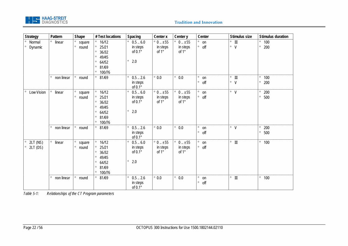
Strategy Pattern Shape # Test locations Spacing Center x Center y Center Stimulus size Stimulus duration ° Normal ° Dynamic
° linear ° square ° round
° 16/12 ° 25/21 ° 36/32 ° 49/45 ° 64/52 ° 81/69 ° 100/76
° 0.5 .. 6.0 in steps of 0.1°
° 2.0
° 0 .. ±55 in steps of 1°
° 0 .. ±55 in steps of 1°
° on ° off
° III ° V
° 100 ° 200
° non linear ° round ° 81/69 ° 0.5 .. 2.6 in steps of 0.1°
° 0.0 ° 0.0 ° on ° off
° III ° V
° 100 ° 200
° Low Vision ° linear ° square ° round
° 16/12 ° 25/21 ° 36/32 ° 49/45 ° 64/52 ° 81/69 ° 100/76
° 0.5 .. 6.0 in steps of 0.1°
° 2.0
° 0 .. ±55 in steps of 1°
° 0 .. ±55 in steps of 1°
° on ° off
° V ° 200 ° 500
° non linear ° round ° 81/69 ° 0.5 .. 2.6 in steps of 0.1°
° 0.0 ° 0.0 ° on ° off
° V ° 200 ° 500
° 2LT (NS) ° 2LT (DS)
° linear ° square ° round
° 16/12 ° 25/21 ° 36/32 ° 49/45 ° 64/52 ° 81/69 ° 100/76
° 0.5 .. 6.0 in steps of 0.1°
° 2.0
° 0 .. ±55 in steps of 1°
° 0 .. ±55 in steps of 1°
° on ° off
° III ° 100
° non linear ° round ° 81/69 ° 0.5 .. 2.6 in steps of 0.1°
° 0.0 ° 0.0 ° on ° off
° III ° 100
Table 5-1: Relationships of the CT Program parameters
Tradition and Innovation
OCTOPUS 300 Instruction for Use Page 23 / 56
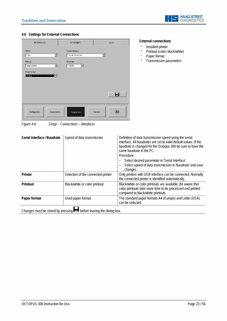
4.6 Settings for External Connections
Figure 4-6: Setup – Connections – Interfaces
External connections ° Installed printer ° Printout (color, black/white) ° Paper format ° Transmission parameters
Serial interface / Baudrate Speed of data transmission Definition of data transmission speed using the serial
interface. All baudrates are set to valid default values. If the baudrate is changed for the Octopus 300 be sure to have the same baudrate in the PC. Procedure: − Select desired parameter in 'Serial interface' − Select speed of data transmission in 'Baudrate' and save
changes. Printer Selection of the connected printer Only printers with USB interface can be connected. Normally
the connected printer is identified automatically. Printout Black/white or color printout Black/white or color printouts are available. Be aware that
color printouts take more time to be processed and printed compared to black/white printouts.
Paper format Used paper format The standard paper formats A4 (Europe) and Letter (USA) can be selected.
Changes must be stored by pressing before leaving the dialog box.
Tradition and Innovation
Page 24 / 56 OCTOPUS 300 Instruction for Use
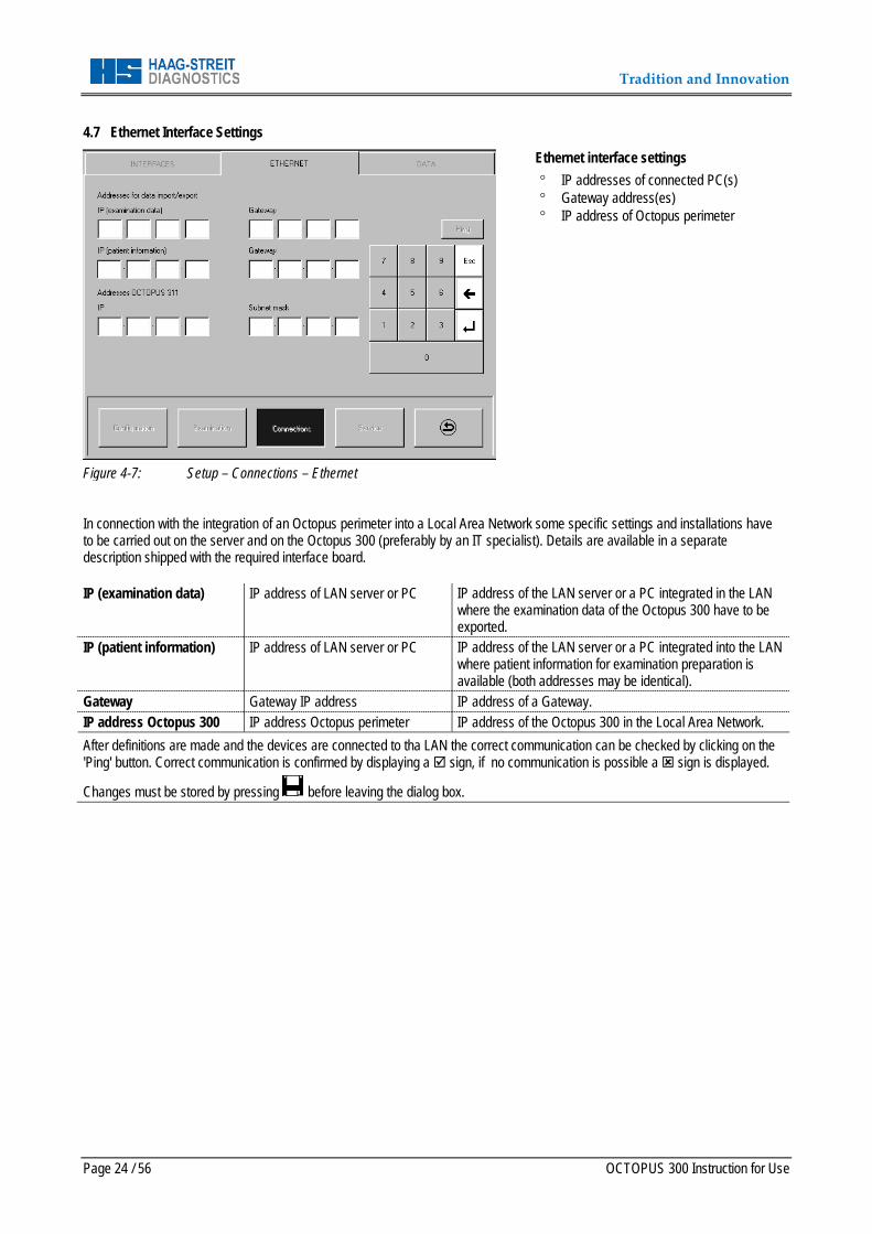
4.7 Ethernet Interface Settings
Figure 4-7: Setup – Connections – Ethernet
Ethernet interface settings ° IP addresses of connected PC(s) ° Gateway address(es) ° IP address of Octopus perimeter
In connection with the integration of an Octopus perimeter into a Local Area Network some specific settings and installations have to be carried out on the server and on the Octopus 300 (preferably by an IT specialist). Details are available in a separate description shipped with the required interface board.
IP (examination data) IP address of LAN server or PC IP address of the LAN server or a PC integrated in the LAN where the examination data of the Octopus 300 have to be exported.
IP (patient information) IP address of LAN server or PC IP address of the LAN server or a PC integrated into the LAN where patient information for examination preparation is available (both addresses may be identical).
Gateway Gateway IP address IP address of a Gateway. IP address Octopus 300 IP address Octopus perimeter IP address of the Octopus 300 in the Local Area Network. After definitions are made and the devices are connected to tha LAN the correct communication can be checked by clicking on the 'Ping' button. Correct communication is confirmed by displaying a sign, if no communication is possible a sign is displayed.
Changes must be stored by pressing before leaving the dialog box.
Tradition and Innovation
OCTOPUS 300 Instruction for Use Page 25 / 56
4.8 Settings for Data Communications
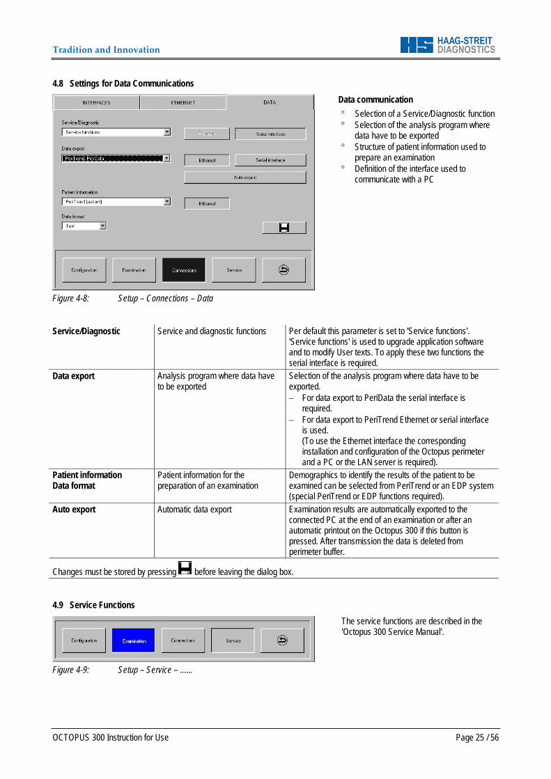
Figure 4-8: Setup – Connections – Data
Data communication ° Selection of a Service/Diagnostic function ° Selection of the analysis program where
data have to be exported ° Structure of patient information used to
prepare an examination ° Definition of the interface used to
communicate with a PC
Service/Diagnostic Service and diagnostic functions Per default this parameter is set to 'Service functions'.
'Service functions' is used to upgrade application software and to modify User texts. To apply these two functions the serial interface is required.
Data export Analysis program where data have to be exported
Selection of the analysis program where data have to be exported. − For data export to PeriData the serial interface is
required. − For data export to PeriTrend Ethernet or serial interface
is used. (To use the Ethernet interface the corresponding installation and configuration of the Octopus perimeter and a PC or the LAN server is required).
Patient information Data format
Patient information for the preparation of an examination
Demographics to identify the results of the patient to be examined can be selected from PeriTrend or an EDP system (special PeriTrend or EDP functions required).
Auto export Automatic data export Examination results are automatically exported to the connected PC at the end of an examination or after an automatic printout on the Octopus 300 if this button is pressed. After transmission the data is deleted from perimeter buffer.
Changes must be stored by pressing before leaving the dialog box. 4.9 Service Functions
Figure 4-9: Setup – Service – ......
The service functions are described in the 'Octopus 300 Service Manual'.
Tradition and Innovation
Page 26 / 56 OCTOPUS 300 Instruction for Use
5 PERFORMING AN EXAMINATION Careful examination preparation helps increasing the reliability of the results. The patient should be informed about the examination process so he or she can cooperate optimally. 5.1 Instructing the Patient Fixation During the entire examination the patient concentrates on the fixation target which is displayed in the center of the field of view. Examination Process At various locations in the field of view stimuli (flashes of light) of a certain duration and intensity are shown. The patient acknowledges that he or she perceives the stimulus by pressings quickly on the patient response button. Perception of the Stimuli It is normal that the patient is unable to see many stimuli. The number depends on the selected examination strategy and the condition of the patient's visual field. Duration of the Examination The duration of the examination depends on the selected examination program and the examination strategy and can range from roughly 3 to 15 minutes. Stopping the Examination Process By closing the eye being examined or holding the patient response button down the patient can stop the examination process. Stimulus Interval The time between two successive stimuli varies according to the instrument settings and the patient response speed of the patient. It can range from roughly 1.5 to 4 seconds. 5.2 Trial Lenses The patient sees the stimuli at infinity and thus his or her eye must be corrected for distance. The spherical lens is put on the patient's side, the cylindrical on the ocular side of the lens holder. For the correct positioning of the cylindrical correction axis the trial lens holder is fitted with marks separated by 10°. The first mark to the above right corresponds to the 0°position. The trial lenses can remain in place during the whole examination. The trial lens holder can be swung out roughly 25° towards the front for changing the trial lenses comfortably. 5.3 Situating the Patient We recommend using a chair in which the back and the seat can be adjusted. Place the chair so that the patient is in as relaxed a posture as possible. An electrically adjustable instrument table (optional) allows the height of the instrument to be fitted to the patient's physical size comfortably. Cover the eye not being examined with the occluder which is included in the accessories, give him or her the patient response button, and explain its operation. Adjust the headrest and table height so that the patient can rest his or her chin on the chin rest without having to alter their posture and so that his or her forehead touches the sensors in the forehead rest (right eye = left indentation, left eye = right indentation). The height of the chin rest should be set using the adjustment knob so that the eye of the patient lies even with the inscribed rings on the two columns.
Tradition and Innovation
OCTOPUS 300 Instruction for Use Page 27 / 56
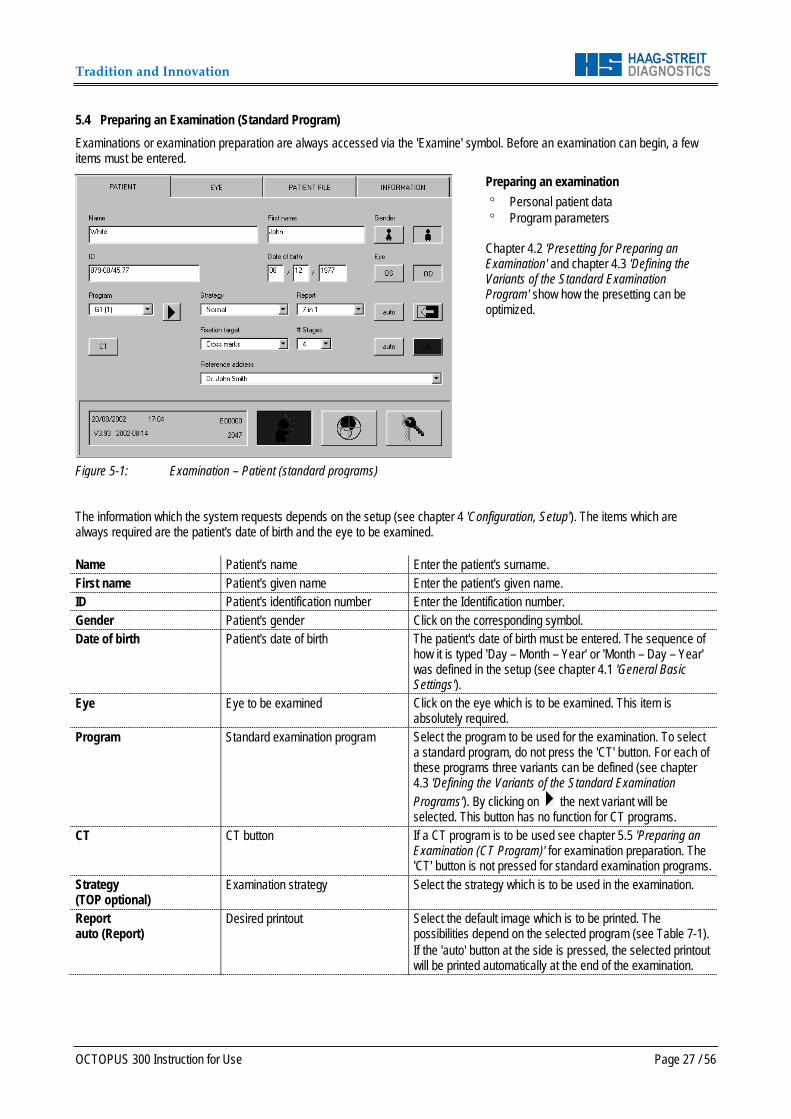
5.4 Preparing an Examination (Standard Program) Examinations or examination preparation are always accessed via the 'Examine' symbol. Before an examination can begin, a few items must be entered.
Figure 5-1: Examination – Patient (standard programs)
Preparing an examination ° Personal patient data ° Program parameters
Chapter 4.2 'Presetting for Preparing an Examination' and chapter 4.3 'Defining the Variants of the Standard Examination Program' show how the presetting can be optimized.
The information which the system requests depends on the setup (see chapter 4 'Configuration, Setup'). The items which are always required are the patient's date of birth and the eye to be examined.
Name Patient's name Enter the patient's surname. First name Patient's given name Enter the patient's given name. ID Patient's identification number Enter the Identification number. Gender Patient's gender Click on the corresponding symbol. Date of birth Patient's date of birth The patient's date of birth must be entered. The sequence of
how it is typed 'Day – Month – Year' or 'Month – Day – Year' was defined in the setup (see chapter 4.1 'General Basic Settings').
Eye Eye to be examined Click on the eye which is to be examined. This item is absolutely required.
Program Standard examination program Select the program to be used for the examination. To select a standard program, do not press the 'CT' button. For each of these programs three variants can be defined (see chapter 4.3 'Defining the Variants of the Standard Examination Programs'). By clicking on the next variant will be selected. This button has no function for CT programs.
CT CT button If a CT program is to be used see chapter 5.5 'Preparing an Examination (CT Program)' for examination preparation. The 'CT' button is not pressed for standard examination programs.
Strategy (TOP optional)
Examination strategy Select the strategy which is to be used in the examination.
Report auto (Report)
Desired printout Select the default image which is to be printed. The possibilities depend on the selected program (see Table 7-1). If the 'auto' button at the side is pressed, the selected printout will be printed automatically at the end of the examination.
Tradition and Innovation
Page 28 / 56 OCTOPUS 300 Instruction for Use
Fixation target Fixation symbol Set the fixation target which is displayed for the patient during the examination. If the selected fixation target collides with a test location, another target is displayed during the corresponding stage.
# Stages auto (# Stages)
Number of examination stages Specify the number of examination stages which should be gone through. If the 'auto' button on the side has been pressed, the program will end after the preset stages have been worked through.
Reference address Address, information on printout Select reference address to be printed in the header of a printout. After clicking on the default address is selected (address which is presented in the 'Setup' – 'Configuration' – 'General' window).
Delete entries, set standard values When an examination is being prepared, the patient data and
the program parameters from the previous examination are offered. After the 'Delete' button is pressed, the patient data is deleted and the program parameters defined in the setup are taken over.
The 'OK' button turns blue when all the required data have been entered. Press 'OK' to start the examination. Examination monitoring and examination procedure are described in chapter 6 'Monitoring an Examination'.
NOTE! The required items can be reduced to a minimum when the setup has been well matched to your needs.
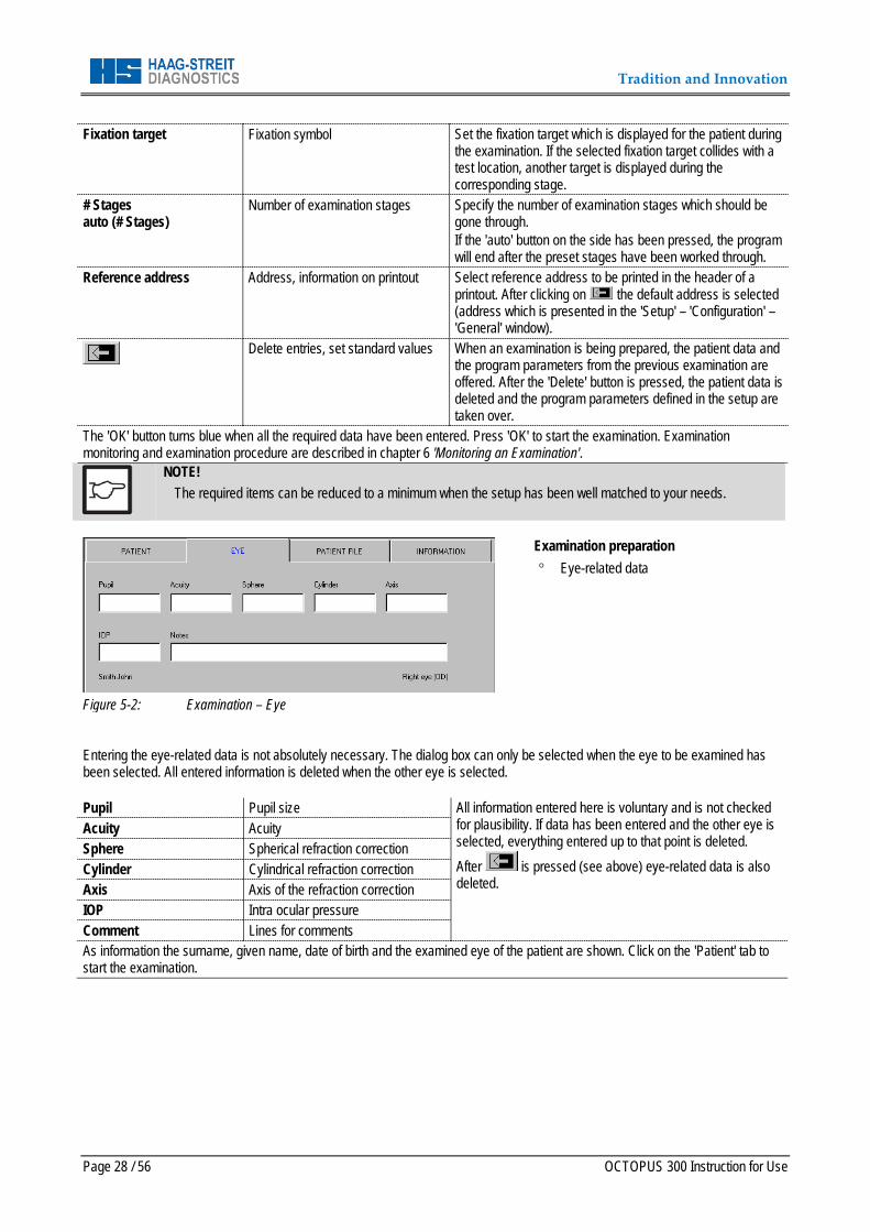
Figure 5-2: Examination – Eye
Examination preparation ° Eye-related data
Entering the eye-related data is not absolutely necessary. The dialog box can only be selected when the eye to be examined has been selected. All entered information is deleted when the other eye is selected.
Pupil Pupil size All information entered here is voluntary and is not checked for plausibility. If data has been entered and the other eye is selected, everything entered up to that point is deleted. After is pressed (see above) eye-related data is also deleted.
Acuity Acuity Sphere Spherical refraction correction Cylinder Cylindrical refraction correction Axis Axis of the refraction correction IOP Intra ocular pressure Comment Lines for comments As information the surname, given name, date of birth and the examined eye of the patient are shown. Click on the 'Patient' tab to start the examination.
Tradition and Innovation
OCTOPUS 300 Instruction for Use Page 29 / 56
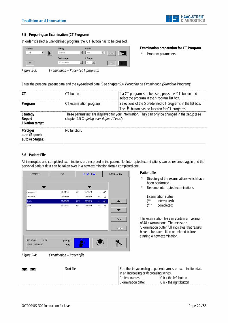
5.5 Preparing an Examination (CT Program) In order to select a user-defined program, the 'CT' button has to be pressed.
Figure 5-3: Examination – Patient (CT program)
Examination preparation for CT Program ° Program parameters
Enter the personal patient data and the eye-related data. See chapter 5.4 'Preparing an Examination (Standard Program)'.
CT CT button If a CT program is to be used, press the 'CT' button and select the program in the 'Program' list box.
Program CT examination program Select one of the 5 predefined CT programs in the list box. The button has no function for CT programs.
Strategy Report Fixation target
These parameters are displayed for your information. They can only be changed in the setup (see chapter 4.5 'Defining user-defined Tests').
# Stages auto (Report) auto (# Stages)
No function.
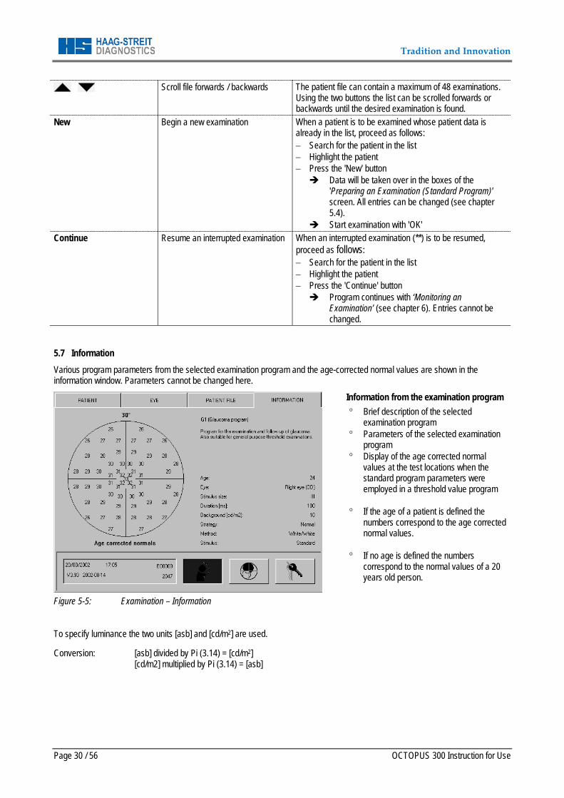
5.6 Patient File All interrupted and completed examinations are recorded in the patient file. Interrupted examinations can be resumed again and the personal patient data can be taken over in a new examination from a completed one.
Figure 5-4: Examination – Patient file
Patient file ° Directory of the examinations which have
been performed ° Resume interrupted examinations
Examination status (** interrupted) (*** completed)
The examination file can contain a maximum of 48 examinations. The message 'Examination buffer full' indicates that results have to be transmitted or deleted before starting a new examination.
Sort file Sort the list according to patient names or examination date in an increasing or decreasing series. Patient names: Click the left button Examination date: Click the right button
Tradition and Innovation
Page 30 / 56 OCTOPUS 300 Instruction for Use
Scroll file forwards / backwards The patient file can contain a maximum of 48 examinations. Using the two buttons the list can be scrolled forwards or backwards until the desired examination is found.
New Begin a new examination When a patient is to be examined whose patient data is already in the list, proceed as follows: − Search for the patient in the list − Highlight the patient − Press the 'New' button Data will be taken over in the boxes of the
'Preparing an Examination (Standard Program)' screen. All entries can be changed (see chapter 5.4).
Start examination with 'OK' Continue Resume an interrupted examination When an interrupted examination (**) is to be resumed,
proceed as follows: − Search for the patient in the list − Highlight the patient − Press the 'Continue' button Program continues with ‘Monitoring an
Examination’ (see chapter 6). Entries cannot be changed.
5.7 Information Various program parameters from the selected examination program and the age-corrected normal values are shown in the information window. Parameters cannot be changed here.
Figure 5-5: Examination – Information
Information from the examination program ° Brief description of the selected
examination program ° Parameters of the selected examination
program ° Display of the age corrected normal
values at the test locations when the standard program parameters were employed in a threshold value program
° If the age of a patient is defined the
numbers correspond to the age corrected normal values.
° If no age is defined the numbers
correspond to the normal values of a 20 years old person.
To specify luminance the two units [asb] and [cd/m2] are used.
Conversion: [asb] divided by Pi (3.14) = [cd/m2] [cd/m2] multiplied by Pi (3.14) = [asb]
Tradition and Innovation
OCTOPUS 300 Instruction for Use Page 31 / 56
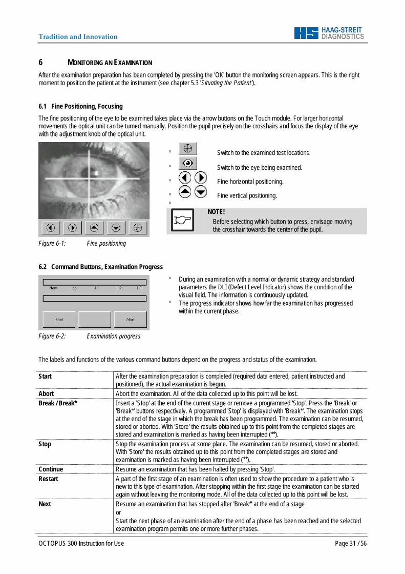
6 MONITORING AN EXAMINATION After the examination preparation has been completed by pressing the 'OK' button the monitoring screen appears. This is the right moment to position the patient at the instrument (see chapter 5.3 'Situating the Patient'). 6.1 Fine Positioning, Focusing The fine positioning of the eye to be examined takes place via the arrow buttons on the Touch module. For larger horizontal movements the optical unit can be turned manually. Position the pupil precisely on the crosshairs and focus the display of the eye with the adjustment knob of the optical unit.
Figure 6-1: Fine positioning
° Switch to the examined test locations.
° Switch to the eye being examined.
° Fine horizontal positioning.
° Fine vertical positioning. °
NOTE! Before selecting which button to press, envisage moving the crosshair towards the center of the pupil.
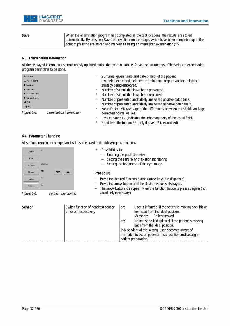
6.2 Command Buttons, Examination Progress
Figure 6-2: Examination progress
° During an examination with a normal or dynamic strategy and standard parameters the DLI (Defect Level Indicator) shows the condition of the visual field. The information is continuously updated.
° The progress indicator shows how far the examination has progressed within the current phase.
The labels and functions of the various command buttons depend on the progress and status of the examination. Start After the examination preparation is completed (required data entered, patient instructed and
positioned), the actual examination is begun. Abort Abort the examination. All of the data collected up to this point will be lost. Break / Break* Insert a 'Stop' at the end of the current stage or remove a programmed 'Stop'. Press the 'Break' or
'Break*' buttons respectively. A programmed 'Stop' is displayed with 'Break*'. The examination stops at the end of the stage in which the break has been programmed. The examination can be resumed, stored or aborted. With 'Store' the results obtained up to this point from the completed stages are stored and examination is marked as having been interrupted (**).
Stop Stop the examination process at some place. The examination can be resumed, stored or aborted. With 'Store' the results obtained up to this point from the completed stages are stored and examination is marked as having been interrupted (**).
Continue Resume an examination that has been halted by pressing 'Stop'. Restart A part of the first stage of an examination is often used to show the procedure to a patient who is
new to this type of examination. After stopping within the first stage the examination can be started again without leaving the monitoring mode. All of the data collected up to this point will be lost.
Next Resume an examination that has stopped after 'Break*' at the end of a stage or Start the next phase of an examination after the end of a phase has been reached and the selected examination program permits one or more further phases.
Tradition and Innovation
Page 32 / 56 OCTOPUS 300 Instruction for Use
Save When the examination program has completed all the test locations, the results are stored automatically. By pressing 'Save' the results from the stages which have been completed up to the point of pressing are stored and marked as being an interrupted examination (**).
6.3 Examination Information All the displayed information is continuously updated during the examination, as far as the parameters of the selected examination program permit this to be done.
Figure 6-3: Examination information
° Surname, given name and date of birth of the patient, eye being examined, selected examination program and examination strategy being employed.
° Number of stimuli that have been presented. ° Number of stimuli that have been repeated. ° Number of presented and falsely answered positive catch trials. ° Number of presented and falsely answered negative catch trials. ° Mean Defect MD (average of the differences between thresholds and age
corrected normal values). ° Loss variance LV (indicates the inhomogeneity of the visual field). ° Short term fluctuation SF (only if phase 2 is examined).
6.4 Parameter Changing All settings remain unchanged and will also be used in the following examinations.
Figure 6-4: Fixation monitoring
° Possibilities for − Entering the pupil diameter − Setting the sensitivity of fixation monitoring − Setting the brightness of the eye image
Procedure − Press the desired function button (arrow keys are displayed). − Press the arrow button until the desired value is displayed. − The arrow buttons disappear when the function button is pressed again (not
absolutely necessary). Sensor Switch function of headrest sensor
on or off respectively on: User is informed, if the patient is moving back his or
her head from the ideal position. Message: Patient moved
off: No message is displayed, if the patient is moving back from the ideal position.
Independent of this setting, user becomes aware of mismatch between patient's head position and setting in patient preparation.

Tradition and Innovation
OCTOPUS 300 Instruction for Use Page 33 / 56
Pupil (automatic) Pupil* (manual)
Pupil size of the eye being examined The pupil diameter can be entered manually or determined by the system. manual: Press the 'Pupil' button and change the
starting value by 0.5 mm with each key click. Starting value:
− 3mm (if no size has been entered during preparation)
− Size which has been entered during preparation
− Size which has been determined by the system
automatic: The pupil diameter is measured after 10 stimuli each, averaged and displayed. At the end of the examination pupil size is stored in the examination results.
Automatic pupil measurement is broken off, if pupil size is entered manually before or during the examination (displayed with Pupil*).
Interval Set the stimulus interval For setting the time between two stimulus presentations. Press the 'Interval' button and change the default value by 0.5 seconds with each key click or set interval to adaptive. fix: Fixed time between 1.5 ... 4 seconds. adaptive: The time interval is matched automatically to
the response behavior (reaction time) of the patient.
Control Sensitivity of the fixation monitoring Press the 'Control' button and change the parameter to the desired value. off: No automatic fixation monitoring. min: Only lid close detection. Deviations of the
pupil from the ideal position are not checked. med: Medium sensitivity of the fixation monitoring. max: Maximum sensitivity of the fixation
monitoring. auto: Automatic fine positioning (option) is
activated. Video Brightness of the displayed eye Press the 'Video' button and change the parameter until the
desired brightness is achieved. Fixation Brightness of the fixation target Press the 'Fixation' button and change the parameter until
the desired brightness is achieved. 6.5 Continuing an interrupted Examination Interrupted examinations can be restarted and resumed. The procedure is described in chapter 5.6 'Patient File'.
Tradition and Innovation
Page 34 / 56 OCTOPUS 300 Instruction for Use
7 ANALYSIS OF EXAMINATION RESULTS The analysis of the examination results consists of: − Displaying results on the monitor − Printing results − Transmitting results to evaluation software on a PC − Changing certain data − Deleting results
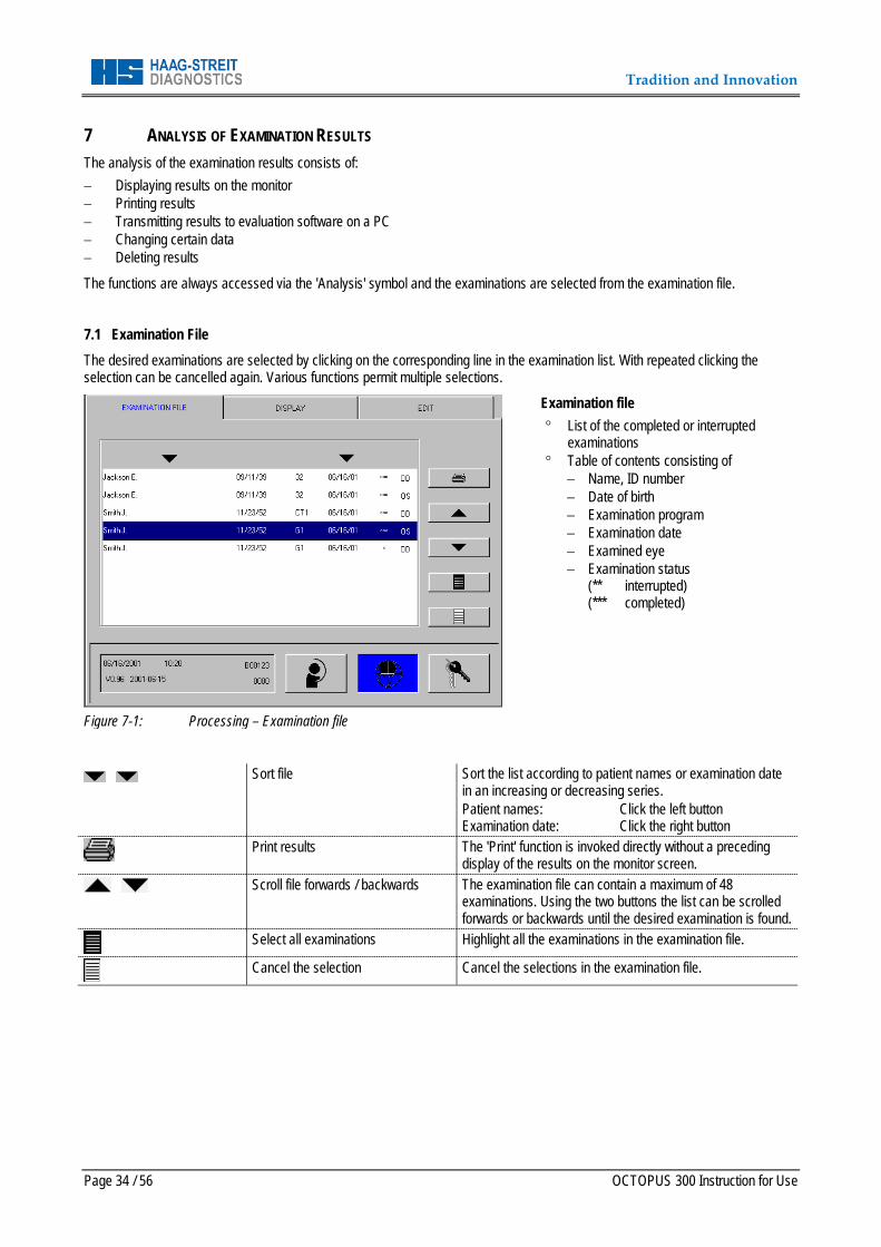
The functions are always accessed via the 'Analysis' symbol and the examinations are selected from the examination file. 7.1 Examination File The desired examinations are selected by clicking on the corresponding line in the examination list. With repeated clicking the selection can be cancelled again. Various functions permit multiple selections.
Figure 7-1: Processing – Examination file
Examination file ° List of the completed or interrupted
examinations ° Table of contents consisting of
− Name, ID number − Date of birth − Examination program − Examination date − Examined eye − Examination status
(** interrupted) (*** completed)
Sort file Sort the list according to patient names or examination date in an increasing or decreasing series. Patient names: Click the left button Examination date: Click the right button
Print results The 'Print' function is invoked directly without a preceding display of the results on the monitor screen.
Scroll file forwards / backwards The examination file can contain a maximum of 48 examinations. Using the two buttons the list can be scrolled forwards or backwards until the desired examination is found.
Select all examinations Highlight all the examinations in the examination file.
Cancel the selection Cancel the selections in the examination file.
Tradition and Innovation
OCTOPUS 300 Instruction for Use Page 35 / 56
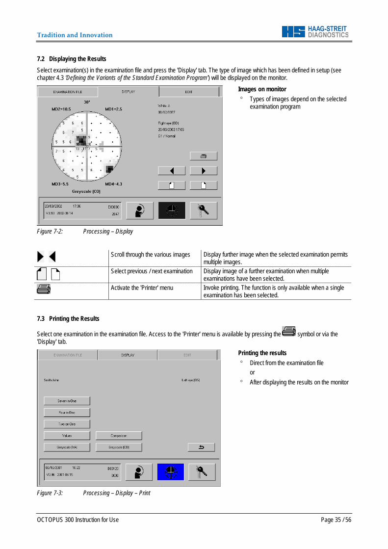
7.2 Displaying the Results Select examination(s) in the examination file and press the 'Display' tab. The type of image which has been defined in setup (see chapter 4.3 'Defining the Variants of the Standard Examination Program') will be displayed on the monitor.
Figure 7-2: Processing – Display
Images on monitor ° Types of images depend on the selected
examination program
Scroll through the various images Display further image when the selected examination permits
multiple images.
Select previous / next examination Display image of a further examination when multiple
examinations have been selected.
Activate the 'Printer' menu Invoke printing. The function is only available when a single examination has been selected.
7.3 Printing the Results
Select one examination in the examination file. Access to the 'Printer' menu is available by pressing the symbol or via the 'Display' tab.
Figure 7-3: Processing – Display – Print
Printing the results ° Direct from the examination file
or ° After displaying the results on the monitor
Tradition and Innovation
Page 36 / 56 OCTOPUS 300 Instruction for Use
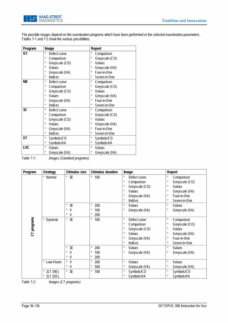
The possible images depend on the examination programs which have been performed or the selected examination parameters. Tables 7-1 and 7-2 show the various possibilities. Program Image Report G1 ° Defect curve
° Comparison ° Greyscale (CO) ° Values ° Greyscale (VA) ° Indices
° Comparison ° Greyscale (CO) ° Values ° Greyscale (VA) ° Four-in-One ° Seven-in-One
M2 ° Defect curve ° Comparison ° Greyscale (CO) ° Values ° Greyscale (VA) ° Indices
° Comparison ° Greyscale (CO) ° Values ° Greyscale (VA) ° Four-in-One ° Seven-in-One
32 ° Defect curve ° Comparison ° Greyscale (CO) ° Values ° Greyscale (VA) ° Indices
° Comparison ° Greyscale (CO) ° Values ° Greyscale (VA) ° Four-in-One ° Seven-in-One
ST ° Symbols/CO ° Symbols/VA
° Symbols/CO ° Symbols/VA
LVC ° Values ° Greyscale (VA)
° Values ° Greyscale (VA)
Table 7-1: Images (Standard programs) Program Strategy Stimulus size Stimulus duration Image Report
CT p
rogr
ams
° Normal ° III ° 100 ° Defect curve ° Comparison ° Greyscale (CO) ° Values ° Greyscale (VA) ° Indices
° Comparison ° Greyscale (CO) ° Values ° Greyscale (VA) ° Four-in-One ° Seven-in-One
° III ° V ° V
° 200 ° 100 ° 200
° Values ° Greyscale (VA)
° Values ° Greyscale (VA)
° Dynamic ° III ° 100 ° Defect curve ° Comparison ° Greyscale (CO) ° Values ° Greyscale (VA) ° Indices
° Comparison ° Greyscale (CO) ° Values ° Greyscale (VA) ° Four-in-One ° Seven-in-One
° III ° V ° V
° 200 ° 100 ° 200
° Values ° Greyscale (VA)
° Values ° Greyscale (VA)
° Low Vision ° V ° V
° 200 ° 500
° Values ° Greyscale (VA)
° Values ° Greyscale (VA)
° 2LT (NS) ° 2LT (DS)
° III ° 100 ° Symbols/CO ° Symbols/VA
° Symbols/CO ° Symbols/VA
Table 7-2: Images (CT programs)
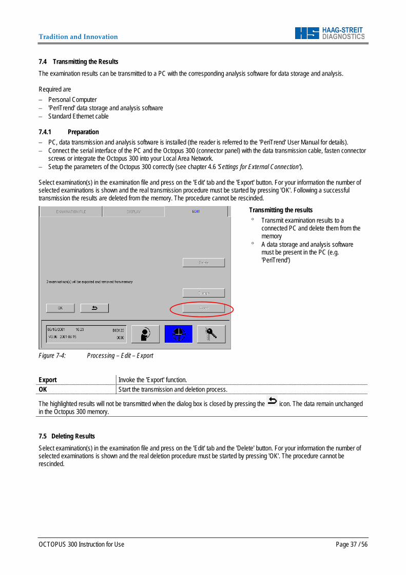
Tradition and Innovation
OCTOPUS 300 Instruction for Use Page 37 / 56
7.4 Transmitting the Results The examination results can be transmitted to a PC with the corresponding analysis software for data storage and analysis. Required are − Personal Computer − 'PeriTrend' data storage and analysis software − Standard Ethernet cable 7.4.1 Preparation − PC, data transmission and analysis software is installed (the reader is referred to the 'PeriTrend' User Manual for details). − Connect the serial interface of the PC and the Octopus 300 (connector panel) with the data transmission cable, fasten connector
screws or integrate the Octopus 300 into your Local Area Network. − Setup the parameters of the Octopus 300 correctly (see chapter 4.6 'Settings for External Connection'). Select examination(s) in the examination file and press on the 'Edit' tab and the 'Export' button. For your information the number of selected examinations is shown and the real transmission procedure must be started by pressing 'OK'. Following a successful transmission the results are deleted from the memory. The procedure cannot be rescinded.
Figure 7-4: Processing – Edit – Export
Transmitting the results ° Transmit examination results to a
connected PC and delete them from the memory
° A data storage and analysis software must be present in the PC (e.g. 'PeriTrend')
Export Invoke the 'Export' function. OK Start the transmission and deletion process.
The highlighted results will not be transmitted when the dialog box is closed by pressing the icon. The data remain unchanged in the Octopus 300 memory. 7.5 Deleting Results Select examination(s) in the examination file and press on the 'Edit' tab and the 'Delete' button. For your information the number of selected examinations is shown and the real deletion procedure must be started by pressing 'OK'. The procedure cannot be rescinded.
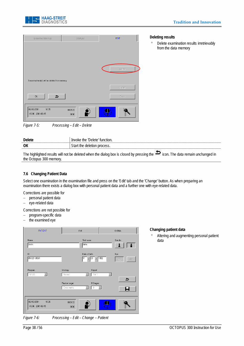
Tradition and Innovation
Page 38 / 56 OCTOPUS 300 Instruction for Use
Figure 7-5: Processing – Edit – Delete
Deleting results ° Delete examination results irretrievably
from the data memory
Delete Invoke the 'Delete' function. OK Start the deletion process.
The highlighted results will not be deleted when the dialog box is closed by pressing the icon. The data remain unchanged in the Octopus 300 memory. 7.6 Changing Patient Data Select one examination in the examination file and press on the 'Edit' tab and the 'Change' button. As when preparing an examination there exists a dialog box with personal patient data and a further one with eye-related data.
Corrections are possible for − personal patient data − eye-related data
Corrections are not possible for − program-specific data − the examined eye
Figure 7-6: Processing – Edit – Change – Patient
Changing patient data ° Altering and augmenting personal patient
data

Tradition and Innovation
OCTOPUS 300 Instruction for Use Page 39 / 56
Figure 7-7: Processing – Edit – Change – Eye
Changing eye-related data ° Altering and augmenting eye-related data
Before leaving the dialog box, changes must be stored by pressing .
Changes are not stored if the dialog box is closed by pressing in which case the former values remain unchanged.
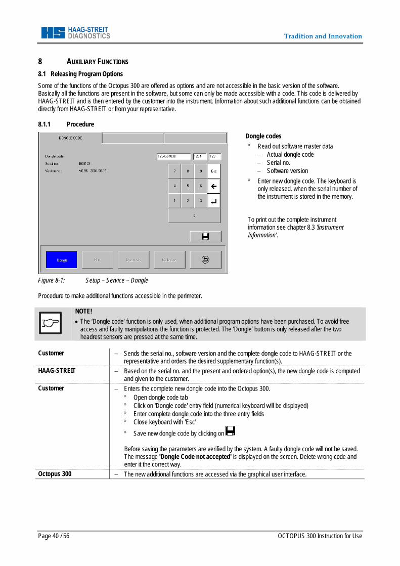
Tradition and Innovation
Page 40 / 56 OCTOPUS 300 Instruction for Use
8 AUXILIARY FUNCTIONS 8.1 Releasing Program Options Some of the functions of the Octopus 300 are offered as options and are not accessible in the basic version of the software. Basically all the functions are present in the software, but some can only be made accessible with a code. This code is delivered by HAAG-STREIT and is then entered by the customer into the instrument. Information about such additional functions can be obtained directly from HAAG-STREIT or from your representative. 8.1.1 Procedure
Figure 8-1: Setup – Service – Dongle
Dongle codes ° Read out software master data
− Actual dongle code − Serial no. − Software version
° Enter new dongle code. The keyboard is only released, when the serial number of the instrument is stored in the memory.
To print out the complete instrument information see chapter 8.3 'Instrument Information'.
Procedure to make additional functions accessible in the perimeter.
NOTE! • The ‘Dongle code‘ function is only used, when additional program options have been purchased. To avoid free
access and faulty manipulations the function is protected. The ‘Dongle‘ button is only released after the two headrest sensors are pressed at the same time.
Customer − Sends the serial no., software version and the complete dongle code to HAAG-STREIT or the
representative and orders the desired supplementary function(s). HAAG-STREIT − Based on the serial no. and the present and ordered option(s), the new dongle code is computed
and given to the customer. Customer − Enters the complete new dongle code into the Octopus 300.
° Open dongle code tab ° Click on 'Dongle code' entry field (numerical keyboard will be displayed) ° Enter complete dongle code into the three entry fields ° Close keyboard with 'Esc' ° Save new dongle code by clicking on Before saving the parameters are verified by the system. A faulty dongle code will not be saved. The message 'Dongle Code not accepted' is displayed on the screen. Delete wrong code and enter it the correct way.
Octopus 300 − The new additional functions are accessed via the graphical user interface.
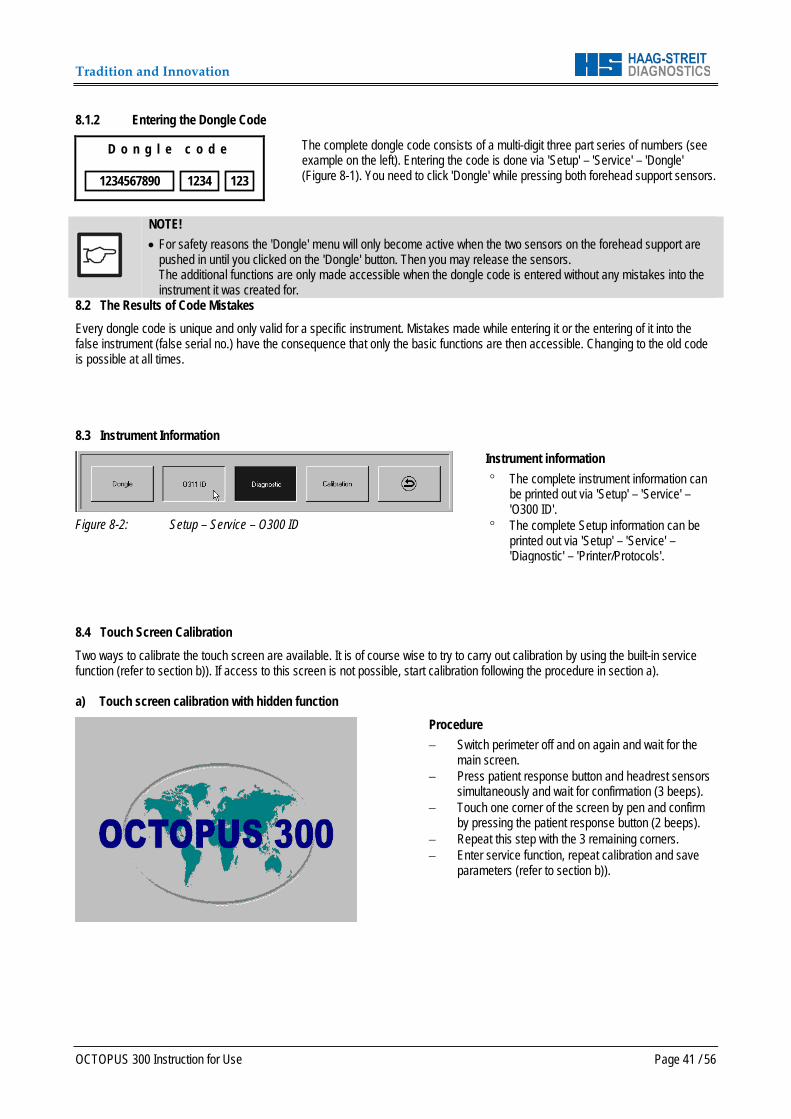
Tradition and Innovation
OCTOPUS 300 Instruction for Use Page 41 / 56
8.1.2 Entering the Dongle Code
D o n g l e c o d e
The complete dongle code consists of a multi-digit three part series of numbers (see example on the left). Entering the code is done via 'Setup' – 'Service' – 'Dongle' (Figure 8-1). You need to click 'Dongle' while pressing both forehead support sensors.
NOTE! • For safety reasons the 'Dongle' menu will only become active when the two sensors on the forehead support are
pushed in until you clicked on the 'Dongle' button. Then you may release the sensors. The additional functions are only made accessible when the dongle code is entered without any mistakes into the instrument it was created for.
8.2 The Results of Code Mistakes Every dongle code is unique and only valid for a specific instrument. Mistakes made while entering it or the entering of it into the false instrument (false serial no.) have the consequence that only the basic functions are then accessible. Changing to the old code is possible at all times. 8.3 Instrument Information
Figure 8-2: Setup – Service – O300 ID
Instrument information ° The complete instrument information can
be printed out via 'Setup' – 'Service' – 'O300 ID'.
° The complete Setup information can be printed out via 'Setup' – 'Service' – 'Diagnostic' – 'Printer/Protocols'.
8.4 Touch Screen Calibration Two ways to calibrate the touch screen are available. It is of course wise to try to carry out calibration by using the built-in service function (refer to section b)). If access to this screen is not possible, start calibration following the procedure in section a). a) Touch screen calibration with hidden function
Procedure − Switch perimeter off and on again and wait for the
main screen. − Press patient response button and headrest sensors
simultaneously and wait for confirmation (3 beeps). − Touch one corner of the screen by pen and confirm
by pressing the patient response button (2 beeps). − Repeat this step with the 3 remaining corners. − Enter service function, repeat calibration and save
parameters (refer to section b)).
1234567890 123 1234
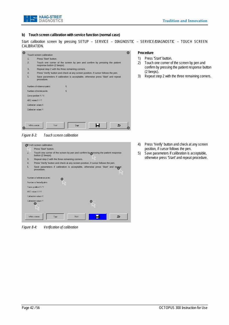
Tradition and Innovation
Page 42 / 56 OCTOPUS 300 Instruction for Use
b) Touch screen calibration with service function (normal case) Start calibration screen by pressing SETUP – SERVICE – DIAGNOSTIC – SERVICE/DIAGNOSTIC – TOUCH SCREEN CALIBRATION.
Figure 8-3: Touch screen calibration
Procedure 1) Press 'Start' button. 2) Touch one corner of the screen by pen and
confirm by pressing the patient response button (2 beeps).
3) Repeat step 2 with the three remaining corners.
Figure 8-4: Verification of calibration
4) Press 'Verify' button and check at any screen position, if cursor follows the pen.
5) Save parameters if calibration is acceptable, otherwise press 'Start' and repeat procedure.
Touch screen calibration 1. Press 'Start' button. 2. Touch one corner of the screen by pen and confirm by pressing the patient
response button (2 beeps). 3. Repeat step 2 with the three remaining corners. 4. Press 'Verify' button and check at any screen position, if cursor follows the pen. 5. Save parameters if calibration is acceptable, otherwise press 'Start' and repeat
procedure.
Touch screen calibration 1. Press 'Start' button. 2. Touch one corner of the screen by pen and confirm by pressing the patient response
button (2 beeps). 3. Repeat step 2 with the three remaining corners. 4. Press 'Verify' button and check at any screen position, if cursor follows the pen. 5. Save parameters if calibration is acceptable, otherwise press 'Start' and repeat
procedure.
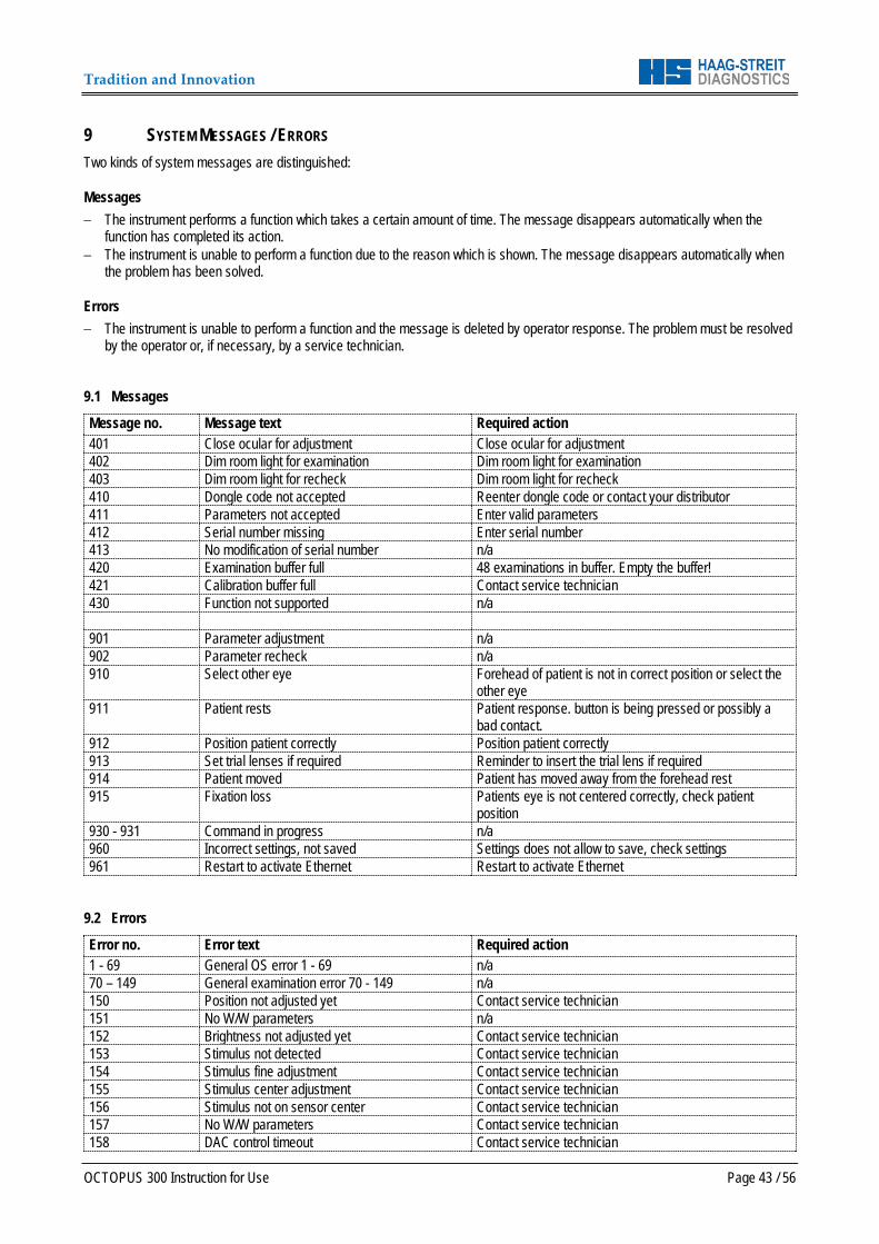
Tradition and Innovation
OCTOPUS 300 Instruction for Use Page 43 / 56
9 SYSTEM MESSAGES / ERRORS Two kinds of system messages are distinguished:
Messages − The instrument performs a function which takes a certain amount of time. The message disappears automatically when the
function has completed its action. − The instrument is unable to perform a function due to the reason which is shown. The message disappears automatically when
the problem has been solved.
Errors − The instrument is unable to perform a function and the message is deleted by operator response. The problem must be resolved
by the operator or, if necessary, by a service technician. 9.1 Messages
Message no. Message text Required action 401 Close ocular for adjustment Close ocular for adjustment 402 Dim room light for examination Dim room light for examination 403 Dim room light for recheck Dim room light for recheck 410 Dongle code not accepted Reenter dongle code or contact your distributor 411 Parameters not accepted Enter valid parameters 412 Serial number missing Enter serial number 413 No modification of serial number n/a 420 Examination buffer full 48 examinations in buffer. Empty the buffer! 421 Calibration buffer full Contact service technician 430 Function not supported n/a 901 Parameter adjustment n/a 902 Parameter recheck n/a 910 Select other eye Forehead of patient is not in correct position or select the
other eye 911 Patient rests Patient response. button is being pressed or possibly a
bad contact. 912 Position patient correctly Position patient correctly 913 Set trial lenses if required Reminder to insert the trial lens if required 914 Patient moved Patient has moved away from the forehead rest 915 Fixation loss Patients eye is not centered correctly, check patient
position 930 - 931 Command in progress n/a 960 Incorrect settings, not saved Settings does not allow to save, check settings 961 Restart to activate Ethernet Restart to activate Ethernet
9.2 Errors
Error no. Error text Required action 1 - 69 General OS error 1 - 69 n/a 70 – 149 General examination error 70 - 149 n/a 150 Position not adjusted yet Contact service technician 151 No W/W parameters n/a 152 Brightness not adjusted yet Contact service technician 153 Stimulus not detected Contact service technician 154 Stimulus fine adjustment Contact service technician 155 Stimulus center adjustment Contact service technician 156 Stimulus not on sensor center Contact service technician 157 No W/W parameters Contact service technician 158 DAC control timeout Contact service technician

Tradition and Innovation
Page 44 / 56 OCTOPUS 300 Instruction for Use
Error no. Error text Required action 159 No user parameters Contact service technician 160 Examination parameter out of range Contact service technician 162 No background light Contact service technician 163 No light on BG sensor Contact service technician 164 No light on S sensor Contact service technician 165 Stimulus intensity recheck Contact service technician 166 Background intensity recheck Contact service technician 167 Reference position lost Contact service technician 168 Wrong stimulus positions Contact service technician 170 No B/Y parameters Contact service technician 171 Stimulus intensity too low Contact service technician 172 Background intensity too low Contact service technician 173 0dB stimulus adjustment range Contact service technician 174 20dB stimulus adjustment range Contact service technician 175 Background adjustment range Contact service technician 176 0dB stimulus out of tolerance Contact service technician 177 20dB stimulus out of tolerance Contact service technician 178 Background out of tolerance Contact service technician 179 0dB stimulus adjustment timeout Contact service technician 180 Too bright for light adjustment Make room dimmer or contact service technician 181 Too bright for position recheck Make room dimmer or contact service technician 182 Stimulus projector timeout Contact service technician 183 Limit switch(es) not reached Contact service technician 184 Limit switch(es) pressed Contact service technician 185 Limit switch(es) detected Contact service technician 186 Upper limit switch not reached Contact service technician 187 Bottom limit switch not reached Contact service technician 188 Left limit switch not reached Contact service technician 189 Right limit switch not reached Contact service technician 190 Upper limit switch pressed Contact service technician 191 Bottom limit switch pressed Contact service technician 192 Left limit switch pressed Contact service technician 193 Right limit switch pressed Contact service technician 194 Upper limit switch detected Contact service technician 195 Bottom limit switch detected Contact service technician 196 Left limit switch detected Contact service technician 197 Right limit switch detected Contact service technician 198 20dB stimulus adjustment timeout Contact service technician 199 Background adjustment timeout Contact service technician 200 No response from PC Check connection to PC or contact service technician 201 PC not ready Check connection to PC or contact service technician 202 Transmission error Check connection to PC or contact service technician 203 Receiver error Check connection to PC or contact service technician 215 Ethernet setup not valid Check connection to PC or contact service technician 216 No response from server Check connection to PC or contact service technician 217 Ethernet transmission error Check connection to PC or contact service technician 218 Ethernet receiver error Check connection to PC or contact service technician 231 Battery low Battery defective, contact service technician 232 USB power failed Contact service technician 233 SIM flash checksum Contact service technician 234 Boot flash checksum Contact service technician 235 Calibration flash checksum Contact service technician 236 Memory error Contact service technician 237 Video RAM error Contact service technician 238 Battery buffer Contact service technician 239 Setup parameters lost After a reset reenter the setup parameters or contact
service technician
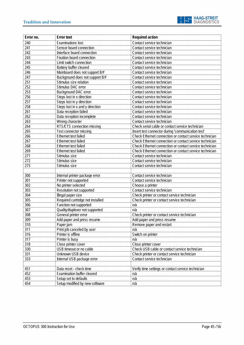
Tradition and Innovation
OCTOPUS 300 Instruction for Use Page 45 / 56
Error no. Error text Required action 240 Examinations lost Contact service technician 241 Sensor board connection Contact service technician 242 Interface board connection Contact service technician 243 Fixation board connection Contact service technician 244 Limit switch connection Contact service technician 245 Battery buffer cleared Contact service technician 246 Mainboard does not support B/Y Contact service technician 247 Background does not support B/Y Contact service technician 251 Stimulus size relation Contact service technician 252 Stimulus DAC error Contact service technician 253 Background DAC error Contact service technician 256 Steps lost in x direction Contact service technician 257 Steps lost in y direction Contact service technician 258 Steps lost in x and y direction Contact service technician 261 Data reception failed Contact service technician 262 Data reception incomplete Contact service technician 263 Wrong character Contact service technician 264 RTS/CTS connection missing Check serial cable or contact service technician 265 Test connector missing Insert test connector during ‘communication test’ 266 Ethernet test failed Check Ethernet connection or contact service technician 267 Ethernet test failed Check Ethernet connection or contact service technician 268 Ethernet test failed Check Ethernet connection or contact service technician 269 Ethernet test failed Check Ethernet connection or contact service technician 271 Stimulus size Contact service technician 272 Stimulus size Contact service technician 273 Stimulus size Contact service technician 300 Internal printer package error Contact service technician 301 Printer not supported Contact service technician 302 No printer selected Choose a printer 303 Resolution not supported Contact service technician 304 Illegal paper size Check printer or contact service technician 305 Required cartridge not installed Check printer or contact service technician 306 Function not supported n/a 307 Quality/duplexer not supported n/a 308 General printer error Check printer or contact service technician 309 Add paper and press resume Add paper and press resume 310 Paper jam Remove paper and restart 311 Print job canceled by user n/a 316 Printer is offline Switch on printer 317 Printer is busy n/a 318 Close printer cover Close printer cover 330 USB timeout or no cable Check USB cable or contact service technician 331 Unknown USB device Check printer or contact service technician 333 Internal USB package error Contact service technician 451 Data reset - check time Verify time settings or contact service technician 452 Examination buffer cleared n/a 453 Setup set to defaults n/a 454 Setup modified by new software n/a

Tradition and Innovation
Page 46 / 56 OCTOPUS 300 Instruction for Use
10 SOFTWARE UPDATES The software update for flash versions 3.05 and higher can be done using a serial cable and the software available on http://www.haag-streit.com/products/perimetry/octopusr-900/software.html . The manual explaining the update procedure can also be downloaded from the website.
NOTE! Prior to any software update you need to printout the personal settings for future reference: Therefore go to 'Setup' – 'Diagnostic' – 'Printer/Protocols' – 'Actual setup' and print the 4 page protocol.
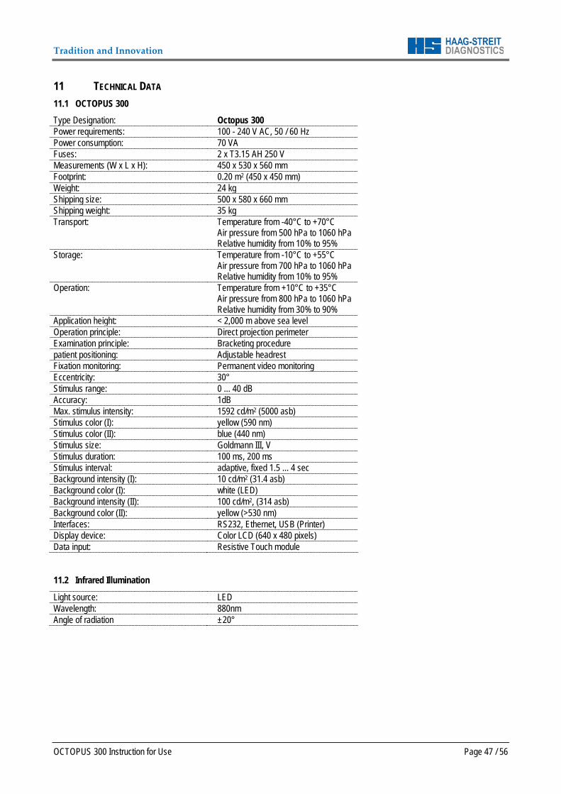
Tradition and Innovation
OCTOPUS 300 Instruction for Use Page 47 / 56
11 TECHNICAL DATA 11.1 OCTOPUS 300 Type Designation: Octopus 300 Power requirements: 100 - 240 V AC, 50 / 60 Hz Power consumption: 70 VA Fuses: 2 x T3.15 AH 250 V Measurements (W x L x H): 450 x 530 x 560 mm Footprint: 0.20 m2 (450 x 450 mm) Weight: 24 kg Shipping size: 500 x 580 x 660 mm Shipping weight: 35 kg Transport: Temperature from -40°C to +70°C
Air pressure from 500 hPa to 1060 hPa Relative humidity from 10% to 95%
Storage: Temperature from -10°C to +55°C Air pressure from 700 hPa to 1060 hPa Relative humidity from 10% to 95%
Operation: Temperature from +10°C to +35°C Air pressure from 800 hPa to 1060 hPa Relative humidity from 30% to 90%
Application height: < 2,000 m above sea level Operation principle: Direct projection perimeter Examination principle: Bracketing procedure patient positioning: Adjustable headrest Fixation monitoring: Permanent video monitoring Eccentricity: 30° Stimulus range: 0 ... 40 dB Accuracy: 1dB Max. stimulus intensity: 1592 cd/m2 (5000 asb) Stimulus color (I): yellow (590 nm) Stimulus color (II): blue (440 nm) Stimulus size: Goldmann III, V Stimulus duration: 100 ms, 200 ms Stimulus interval: adaptive, fixed 1.5 ... 4 sec Background intensity (I): 10 cd/m2 (31.4 asb) Background color (I): white (LED) Background intensity (II): 100 cd/m2, (314 asb) Background color (II): yellow (>530 nm) Interfaces: RS232, Ethernet, USB (Printer) Display device: Color LCD (640 x 480 pixels) Data input: Resistive Touch module
11.2 Infrared Illumination
Light source: LED Wavelength: 880nm Angle of radiation ±20°
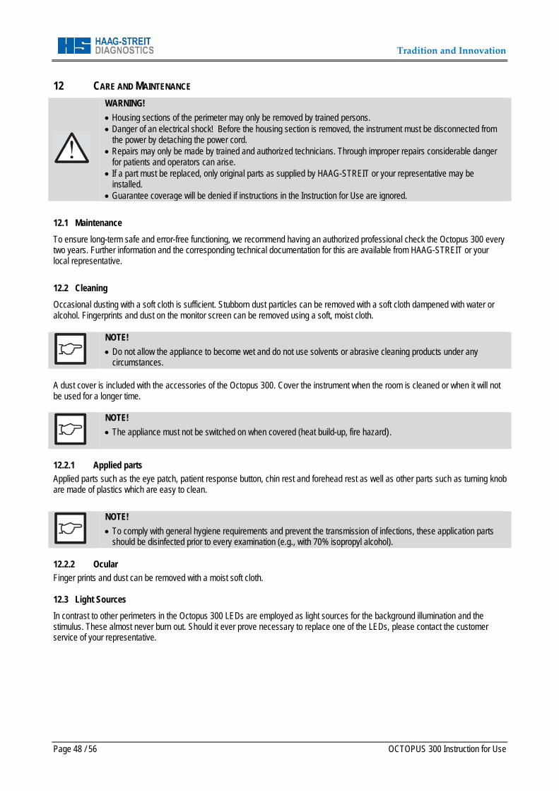
Tradition and Innovation
Page 48 / 56 OCTOPUS 300 Instruction for Use
12 CARE AND MAINTENANCE
WARNING! • Housing sections of the perimeter may only be removed by trained persons. • Danger of an electrical shock! Before the housing section is removed, the instrument must be disconnected from
the power by detaching the power cord. • Repairs may only be made by trained and authorized technicians. Through improper repairs considerable danger
for patients and operators can arise. • If a part must be replaced, only original parts as supplied by HAAG-STREIT or your representative may be
installed. • Guarantee coverage will be denied if instructions in the Instruction for Use are ignored.
12.1 Maintenance To ensure long-term safe and error-free functioning, we recommend having an authorized professional check the Octopus 300 every two years. Further information and the corresponding technical documentation for this are available from HAAG-STREIT or your local representative. 12.2 Cleaning Occasional dusting with a soft cloth is sufficient. Stubborn dust particles can be removed with a soft cloth dampened with water or alcohol. Fingerprints and dust on the monitor screen can be removed using a soft, moist cloth.
NOTE! • Do not allow the appliance to become wet and do not use solvents or abrasive cleaning products under any
circumstances. A dust cover is included with the accessories of the Octopus 300. Cover the instrument when the room is cleaned or when it will not be used for a longer time.
NOTE! • The appliance must not be switched on when covered (heat build-up, fire hazard).
12.2.1 Applied parts Applied parts such as the eye patch, patient response button, chin rest and forehead rest as well as other parts such as turning knob are made of plastics which are easy to clean.
NOTE! • To comply with general hygiene requirements and prevent the transmission of infections, these application parts
should be disinfected prior to every examination (e.g., with 70% isopropyl alcohol). 12.2.2 Ocular Finger prints and dust can be removed with a moist soft cloth. 12.3 Light Sources In contrast to other perimeters in the Octopus 300 LEDs are employed as light sources for the background illumination and the stimulus. These almost never burn out. Should it ever prove necessary to replace one of the LEDs, please contact the customer service of your representative.
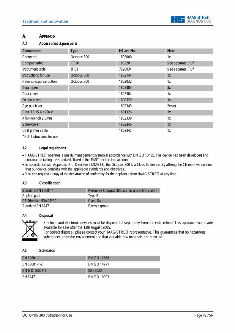
Tradition and Innovation
OCTOPUS 300 Instruction for Use Page 49 / 56
A. APPENDIX A.1 Accessories /spare parts
Component Type HS art. No. Note Perimeter Octopus 300 1805000 1x Compact table CT 01 1802281 See separate IFU* Instrument table IT 01 7220034 See separate IFU* Instructions for use Octopus 300 1802144 1x Patient response button Octopus 300 1802032 1x Touch pen 1802303 3x Dust cover 1802304 1x Ocular cover 1800339 1x Eye patch set 1802349 2x/set Fuse T3.15 A / 250 V 1801326 1x Allen wrench 2.5mm 1802338 1x Screwdriver 1802345 1x USB printer cable 1802347 1x *IFU=Instructions for use A2. Legal regulations
• HAAG-STREIT operates a quality management system in accordance with EN ISO 13485. The device has been developed and constructed taking the standards listed in the 'EMC' section into account.
• In accordance with Appendix IX of Directive 93/42/EEC, the Octopus 300 is a Class IIa device. By affixing the CE mark we confirm that our device complies with the applicable standards and directives.
• You can request a copy of the declaration of conformity for the appliance from HAAG-STREIT at any time. A3. Classification
Standard EN 60601-1: Perimeter Octopus 300 acc. to protection class I Applied part: Type B CE Directive 93/42/EEC Class IIa Standard EN 62471 Exempt group A4. Disposal
Electrical and electronic devices must be disposed of separately from domestic refuse! This appliance was made available for sale after the 13th August 2005. For correct disposal, please contact your HAAG-STREIT representative. This guarantees that no hazardous substances enter the environment and that valuable raw materials are recycled.
A5. Standards
EN 60601-1 EN ISO 12866 EN 60601-1-2 EN ISO 14971 EN ISO 15004-1 ISO 9022 EN 62471 EN ISO 10993

Tradition and Innovation
Page 50 / 56 OCTOPUS 300 Instruction for Use
A5. RoHS China Environment friendly use period (EFUP). The following formula applies for products that can be repaired:
𝐸𝐸 =𝑇𝑇𝑇ℎ𝑛𝑛𝑇𝑛𝑛 𝑠𝑇𝑠𝑠𝑛𝑇𝑇 𝑛𝑛𝑙𝑇 × 125%
(𝐷𝑛𝑛𝑛𝐷 𝑢𝑠𝑇) × 365
125% = Factor for products which can be repaired. Daily use = service use, from field tests Average data: 21,900 patient/year, 10 minutes/patient.
𝐷𝑛𝑛𝑛𝐷 𝑢𝑠𝑇 =21900 × 8.5
60 × 365= 8.5 ℎ𝑜𝑢𝑠𝑠 𝑝𝑇𝑠 𝑑𝑛𝐷
Technical service life ~ 30,000 hours.
𝐸𝐸𝐸𝐸 =30000 × 125%
8.5 × 365= 12.1 𝐷𝑇𝑛𝑠𝑠
Consequently, the environment friendly use period is approx. 12 years.
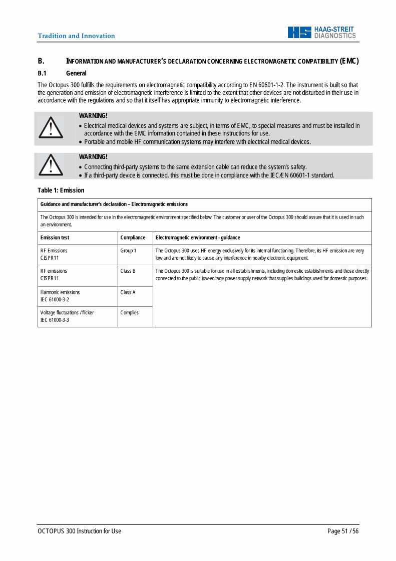
Tradition and Innovation
OCTOPUS 300 Instruction for Use Page 51 / 56
B. INFORMATION AND MANUFACTURER’S DECLARATION CONCERNING ELECTROMAGNETIC COMPATIBILITY (EMC) B.1 General The Octopus 300 fulfills the requirements on electromagnetic compatibility according to EN 60601-1-2. The instrument is built so that the generation and emission of electromagnetic interference is limited to the extent that other devices are not disturbed in their use in accordance with the regulations and so that it itself has appropriate immunity to electromagnetic interference.
WARNING! • Electrical medical devices and systems are subject, in terms of EMC, to special measures and must be installed in
accordance with the EMC information contained in these instructions for use. • Portable and mobile HF communication systems may interfere with electrical medical devices.
WARNING! • Connecting third-party systems to the same extension cable can reduce the system's safety. • If a third-party device is connected, this must be done in compliance with the IEC/EN 60601-1 standard.
Table 1: Emission
Guidance and manufacturer's declaration – Electromagnetic emissions
The Octopus 300 is intended for use in the electromagnetic environment specified below. The customer or user of the Octopus 300 should assure that it is used in such an environment.
Emission test Compliance Electromagnetic environment - guidance
RF Emissions CISPR11
Group 1 The Octopus 300 uses HF energy exclusively for its internal functioning. Therefore, its HF emission are very low and are not likely to cause any interference in nearby electronic equipment.
RF emissions CISPR11
Class B The Octopus 300 is suitable for use in all establishments, including domestic establishments and those directly connected to the public low-voltage power supply network that supplies buildings used for domestic purposes.
Harmonic emissions IEC 61000-3-2
Class A
Voltage fluctuations / flicker IEC 61000-3-3
Complies
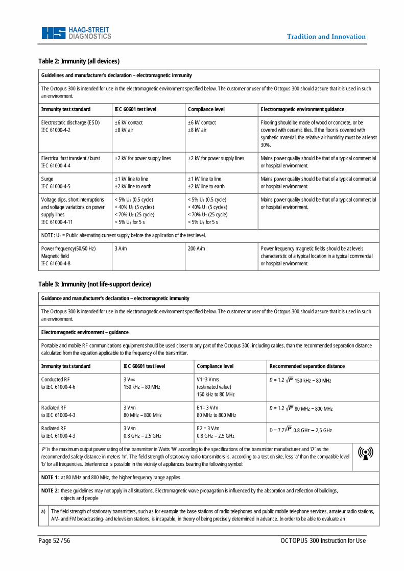
Tradition and Innovation
Page 52 / 56 OCTOPUS 300 Instruction for Use
Table 2: Immunity (all devices)
Guidelines and manufacturer's declaration – electromagnetic immunity
The Octopus 300 is intended for use in the electromagnetic environment specified below. The customer or user of the Octopus 300 should assure that it is used in such an environment.
Immunity test standard IEC 60601 test level Compliance level Electromagnetic environment guidance
Electrostatic discharge (ESD) IEC 61000-4-2
±6 kV contact ±8 kV air
±6 kV contact ±8 kV air
Flooring should be made of wood or concrete, or be covered with ceramic tiles. If the floor is covered with synthetic material, the relative air humidity must be at least 30%.
Electrical fast transient / burst IEC 61000-4-4
±2 kV for power supply lines ±2 kV for power supply lines Mains power quality should be that of a typical commercial or hospital environment.
Surge IEC 61000-4-5
±1 kV line to line ±2 kV line to earth
±1 kV line to line ±2 kV line to earth
Mains power quality should be that of a typical commercial or hospital environment.
Voltage dips, short interruptions and voltage variations on power supply lines IEC 61000-4-11
< 5% UT (0.5 cycle) < 40% UT (5 cycles) < 70% UT (25 cycle) < 5% UT for 5 s
< 5% UT (0.5 cycle) < 40% UT (5 cycles) < 70% UT (25 cycle) < 5% UT for 5 s
Mains power quality should be that of a typical commercial or hospital environment.
NOTE: UT = Public alternating current supply before the application of the test level.
Power frequency(50/60 Hz) Magnetic field IEC 61000-4-8
3 A/m 200 A/m Power frequency magnetic fields should be at levels characteristic of a typical location in a typical commercial or hospital environment.
Table 3: Immunity (not life-support device)
Guidance and manufacturer's declaration – electromagnetic immunity
The Octopus 300 is intended for use in the electromagnetic environment specified below. The customer or user of the Octopus 300 should assure that it is used in such an environment.
Electromagnetic environment – guidance
Portable and mobile RF communications equipment should be used closer to any part of the Octopus 300, including cables, than the recommended separation distance calculated from the equation applicable to the frequency of the transmitter.
Immunity test standard IEC 60601 test level Compliance level Recommended separation distance
Conducted RF to IEC 61000-4-6
3 Vrms 150 kHz – 80 MHz
V1=3 Vrms (estimated value) 150 kHz to 80 MHz
D = 1.2 150 kHz – 80 MHz
Radiated RF to IEC 61000-4-3
3 V/m 80 MHz – 800 MHz
E1= 3 V/m 80 MHz to 800 MHz
D = 1.2 80 MHz – 800 MHz
Radiated RF to IEC 61000-4-3
3 V/m 0.8 GHz – 2,5 GHz
E2 = 3 V/m 0.8 GHz – 2.5 GHz
D = 7.7 0.8 GHz – 2,5 GHz
'P' is the maximum output power rating of the transmitter in Watts 'W' according to the specifications of the transmitter manufacturer and ’D’ as the recommended safety distance in meters 'm'. The field strength of stationary radio transmitters is, according to a test on site, less 'a' than the compatible level 'b' for all frequencies. Interference is possible in the vicinity of appliances bearing the following symbol:
NOTE 1: at 80 MHz and 800 MHz, the higher frequency range applies.
NOTE 2: these guidelines may not apply in all situations. Electromagnetic wave propagation is influenced by the absorption and reflection of buildings, objects and people
a)
The field strength of stationary transmitters, such as for example the base stations of radio telephones and public mobile telephone services, amateur radio stations, AM- and FM broadcasting- and television stations, is incapable, in theory of being precisely determined in advance. In order to be able to evaluate an

Tradition and Innovation
OCTOPUS 300 Instruction for Use Page 53 / 56
b) c)
electromagnetic environment after the installation of high frequency stationary transmitters, an examination of the location is to be recommended. When the measured field strength at the location of an Octopus 300 exceeds the above compatibility level, then the normal operating conditions of the Octopus 300 at that particular location will have to be more closely examined. If unusual power emission characteristics are observed, then it may be necessary to take additional measures, e.g. the reorientation or relocation or conversion of the Octopus 300. The field strength is lower than 3 V/m throughout a frequency band from 150 kHz – 80 MHz Possible shorter distances outside ISM bands are not considered to have a better applicability.
Table 4: Recommended separation distances (not life-support equipment)
Recommended separation distances between portable and mobile. RF communications equipment and the Octopus 300
The Octopus 300 is intended for use in the electromagnetic environment in which radiated RF disturbances are controlled. The customer or the user of the Octopus 300 can help prevent electromagnetic interference by maintaining a minimum distance between portable and mobile RF communications equipment (transmitters) and the Octopus 300 as recommended as below, according to the maximum output power of the communications equipment.
Rated maximum output power of transmitter [W]
Separation distance according to frequency of transmitter [m]
150 kHz – 80 MHz D = 1.2
80 MHz – 800 MHz D = 1.2
800 MHz – 2.5 MHz D = 7.7
0.01 0.12 0.12 0.77
0.1 0.38 0.38 2.5
1 1.2 1.2 7.7
10 3.8 3.8 25
100 12 12 77
For transmitters rated at a maximum output power not listed above, the recommended separation distance D in meters [m] can be estimated using the equation applicable to the transmitter, where P is the maximum output power rating of the transmitter in watts [W] according to the transmitter manufacturer.
NOTE 1: At 80 MHz and 800 MHz, the separation distance for the higher frequency range applies.
NOTE 2: These guidelines may not be valid for all situations. Electromagnetic propagation is affected by absorption and reflection from structures, objects and people.
NOTE 3: An addition factor of 10/3 is used in calculating the recommended separation distance to decrease the likelihood that mobile/portable communications equipment could cause interference if it is inadvertently brought into patient areas.

Tradition and Innovation
Page 54 / 56 OCTOPUS 300 Instruction for Use
Notes

Tradition and Innovation
OCTOPUS 300 Instruction for Use Page 55 / 56
Notes

Tradition and Innovation
Page 56 / 56 OCTOPUS 300 Instruction for Use
Should you have any further questions, please contact your HAAG-STREIT representative at: