Embed Size (px)
Citation preview
1
OECD Nuclear Energy Agency
Nuclear Science Committee
Working Party of the Physics of Plutonium Fuels and Innovative Fuel Cycles
OECD/NEA AND U.S. NRC PWR MOX/UO2 CORE TRANSIENT BENCHMARK
Tomasz Kozlowski and Thomas J. Downar Purdue University
West Lafayette, Indiana U.S.A.
Final Specifications, Revision 2 December 2003
2
INTRODUCTION Computational benchmarks based on well defined problems with a complete set of input and a unique solution are often used as a means of verifying the reliability of numerical solutions. The problems usually employ some simplifications in order to make the analysis manageable and to enable the consistent comparison of several different models, yet complex enough to make the problem applicable to actual core designs. The present benchmark is designed to provide the framework to assess the ability of modern reactor kinetic codes to predict the transient response of a core partially loaded with MOX fuel. This benchmark employs many of the characteristics of the NEACRP L-335 PWR benchmark proposed by Finnemann in 1991 [Finnemann, 1991] which was designed to assess the ability of spatial kinetics codes to model rod ejection transients. The current problem adds the complexity of modeling a rod eject in a core fueled partially with weapons grade MOX. The core chosen for the simulation is based on four-loop Westinghouse PWR power plant similar to the reactor chosen for Plutonium disposition in the U.S. The rod ejection may occur in a PWR as a consequence of the rupture of the drive mechanism casing located on the reactor pressure vessel. This event is of particular concern for MOX fueled cores since the delayed neutron fraction in MOX fuel is significantly smaller than UO2 cores. The rod ejection transient can result in significant, localized perturbations of the neutronic and thermo-hydraulic core parameters which can be difficult for reactor core simulators to predict accurately, particularly in a heterogeneous MOX fueled core. The problem geometry simulated here is a full PWR core in order to allow the realistic simulation of a single rod ejection. The problem is designed primarily to assess core simulators, therefore, few group constants are specified at the level of homogenized assembly and homogenized pin cells. However, some participants may wish to utilize their own cross section generation codes or to model explicitly the heterogeneous pins in their core simulators. Therefore, the benchmark also specifies material compositions and pin geometries in order to reach the widest range of participants and to be applicable to continuing code developments in which heterogeneous full core transport transients are becoming possible. This work has been performed under the auspices of OECD/NEA Working Party on the Physics of Plutonium Fuels and Innovative Fuel Cycles (WPPR). It is sponsored by U.S. NRC and OECD/NEA.

3
1) Problem Statement. The objective of this problem is to evaluate core simulators through the following sequence of calculations: a) multiplication factor, rod worth, assembly and pin power at fixed T/H conditions b) critical boron concentration, assembly and pin power at HFP and HZP c) ejection of control rod transient from HZP conditions HFP conditions correspond to the core power of 100.0 % rated power (3565 MW), inlet coolant temperature of 560 K, inlet pressure of 15.5 MPa. HZP conditions correspond to the core power of 10-4 % rated power, inlet coolant temperature of 560 K, inlet pressure of 15.5 MPa. Appendix A contains submittal checklists with detailed conditions for all calculations. The rod is assumed to be fully ejected in 0.1 seconds after which no reactor scram is considered. The control rod ejection is to be performed from HZP, All Control Banks In, All Shutdown Banks Out, critical boron concentration with the highest worth rod at such condition. During the entire calculation the boron concentration and the position of the other control rods are assumed to be constant. The transient is to be calculated for 1.0 sec. 2) Core Configuration (1/4 core).
1 2 3 4 5 6 7 8U 4.2% U 4.2% U 4.2% U 4.5% U 4.5% M 4.3% U 4.5% U 4.2%
A (CR-D) (CR-A) (CR-SD) (CR-C)35.0 0.15 22.5 0.15 37.5 17.5 0.15 32.5
U 4.2% U 4.2% U 4.5% M 4.0% U 4.2% U 4.2% M 4.0% U 4.5%B (CR-SB)
0.15 17.5 32.5 22.5 0.15 32.5 0.15 17.5U 4.2% U 4.5% U 4.2% U 4.2% U 4.2% M 4.3% U 4.5% M 4.3%
C (CR-A) (CR-C) (CR-B)22.5 32.5 22.5 0.15 22.5 17.5 0.15 35.0
U 4.5% M 4.0% U 4.2% M 4.0% U 4.2% U 4.5% M 4.3% U 4.5%D (CR-SC)
0.15 22.5 0.15 37.5 0.15 20.0 0.15 20.0U 4.5% U 4.2% U 4.2% U 4.2% U 4.2% U 4.5% U 4.2%
E (CR-SD) (CR-D) (CR-SA)37.5 0.15 22.5 0.15 37.5 0.15 17.5
M 4.3% U 4.2% M 4.3% U 4.5% U 4.5% M 4.3% U 4.5% CR-A Control Rod Bank AF (CR-SB) (CR-SC) CR-B Control Rod Bank B
17.5 32.5 17.5 20.0 0.15 0.15 32.5 CR-C Control Rod Bank CU 4.5% M 4.0% U 4.5% M 4.3% U 4.2% U 4.5% Assembly Type CR-D Control Rod Bank D
G (CR-C) (CR-B) (CR-SA) CR Position CR-SA Shutdown Rod Bank A0.15 0.15 0.15 0.15 17.5 32.5 Burnup [GWd/t] CR-SB Shutdown Rod Bank B
U 4.2% U 4.5% M 4.3% U 4.5% Fresh CR-SC Shutdown Rod Bank CH Once Burn CR-SD Shutdown Rod Bank D
32.5 17.5 35.0 20.0 Twice Burn O Ejected Rod
Figure 1 Core Configuration.
4
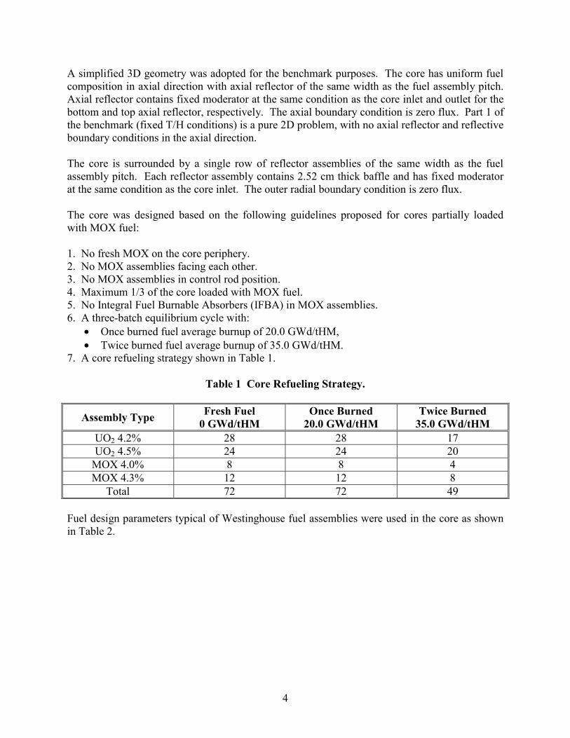
A simplified 3D geometry was adopted for the benchmark purposes. The core has uniform fuel composition in axial direction with axial reflector of the same width as the fuel assembly pitch. Axial reflector contains fixed moderator at the same condition as the core inlet and outlet for the bottom and top axial reflector, respectively. The axial boundary condition is zero flux. Part 1 of the benchmark (fixed T/H conditions) is a pure 2D problem, with no axial reflector and reflective boundary conditions in the axial direction. The core is surrounded by a single row of reflector assemblies of the same width as the fuel assembly pitch. Each reflector assembly contains 2.52 cm thick baffle and has fixed moderator at the same condition as the core inlet. The outer radial boundary condition is zero flux. The core was designed based on the following guidelines proposed for cores partially loaded with MOX fuel: 1. No fresh MOX on the core periphery. 2. No MOX assemblies facing each other. 3. No MOX assemblies in control rod position. 4. Maximum 1/3 of the core loaded with MOX fuel. 5. No Integral Fuel Burnable Absorbers (IFBA) in MOX assemblies. 6. A three-batch equilibrium cycle with:
• Once burned fuel average burnup of 20.0 GWd/tHM, • Twice burned fuel average burnup of 35.0 GWd/tHM.
7. A core refueling strategy shown in Table 1.
Table 1 Core Refueling Strategy.
Assembly Type Fresh Fuel 0 GWd/tHM
Once Burned 20.0 GWd/tHM
Twice Burned 35.0 GWd/tHM
UO2 4.2% 28 28 17 UO2 4.5% 24 24 20
MOX 4.0% 8 8 4 MOX 4.3% 12 12 8
Total 72 72 49 Fuel design parameters typical of Westinghouse fuel assemblies were used in the core as shown in Table 2.
5
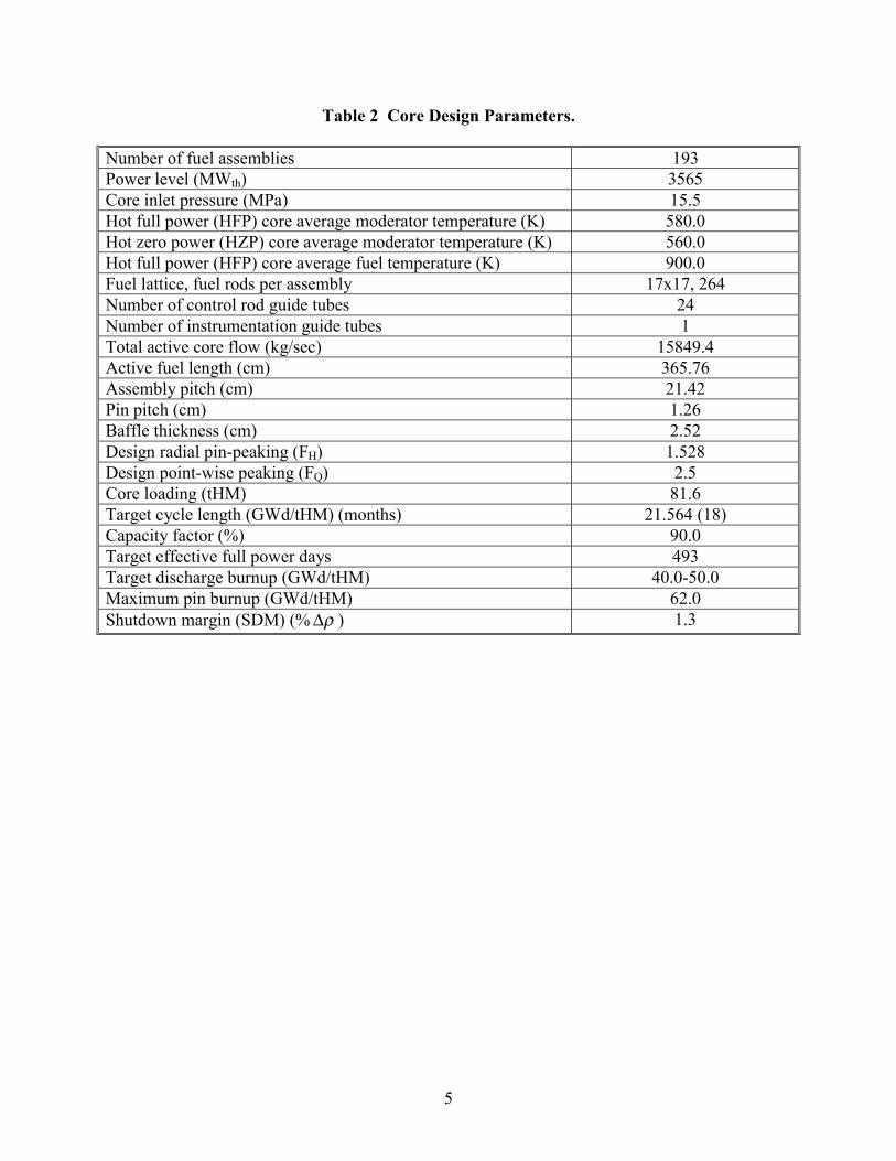
Table 2 Core Design Parameters. Number of fuel assemblies 193 Power level (MWth) 3565 Core inlet pressure (MPa) 15.5 Hot full power (HFP) core average moderator temperature (K) 580.0 Hot zero power (HZP) core average moderator temperature (K) 560.0 Hot full power (HFP) core average fuel temperature (K) 900.0 Fuel lattice, fuel rods per assembly 17x17, 264 Number of control rod guide tubes 24 Number of instrumentation guide tubes 1 Total active core flow (kg/sec) 15849.4 Active fuel length (cm) 365.76 Assembly pitch (cm) 21.42 Pin pitch (cm) 1.26 Baffle thickness (cm) 2.52 Design radial pin-peaking (FH) 1.528 Design point-wise peaking (FQ) 2.5 Core loading (tHM) 81.6 Target cycle length (GWd/tHM) (months) 21.564 (18) Capacity factor (%) 90.0 Target effective full power days 493 Target discharge burnup (GWd/tHM) 40.0-50.0 Maximum pin burnup (GWd/tHM) 62.0 Shutdown margin (SDM) (% ρ∆ ) 1.3
6
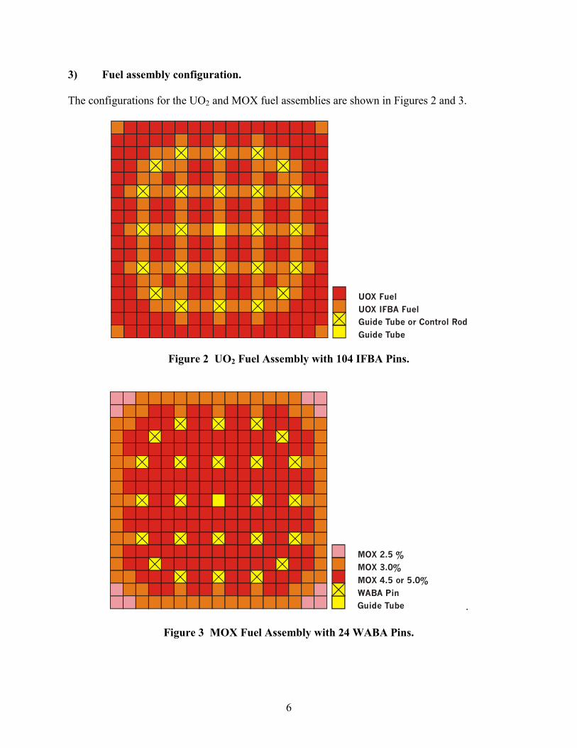
3) Fuel assembly configuration. The configurations for the UO2 and MOX fuel assemblies are shown in Figures 2 and 3.
UOX Fuel
UOX IFBA FuelGuide Tube or Control Rod
Guide Tube
Figure 2 UO2 Fuel Assembly with 104 IFBA Pins.
MOX 4.5 or 5.0%
MOX 3.0%
MOX 2.5 %
Guide TubeWABA Pin
.
Figure 3 MOX Fuel Assembly with 24 WABA Pins.

7
4) Material Compositions. The material compositions for each of the fuel pin types are specified in Tables 3, 4, and 5.
Table 3 Heavy Metal Composition in Fuel.
Assembly Type
Density [g/cm3] HM Material
UO2 4.2% 10.24 U-235: 4.2 wt%, U-238: 95.8 wt% UO2 4.5% 10.24 U-235: 4.5 wt%, U-238: 95.5 wt%
Corner zone: 2.5 wt% Pu-fissile Peripheral zone:
3.0 wt% Pu-fissile MOX 4.0% 10.41
Central zone: 4.5 wt% Pu-fissile
Corner zone: 2.5 wt% Pu-fissile Peripheral zone:
3.0 wt% Pu-fissile MOX 4.3% 10.41
Central zone: 5.0 wt% Pu-fissile
Uranium vector: 234/235/236/238 =
0.002/0.2/0.001/99.797 wt%
Plutonium vector: 239/240/241/242 =
93.6/5.9/0.4/0.1 wt%
Table 4 Other Burnable Materials.
Absorber material
Density [g/cm3] Material
Control Rod 1.84 B4C IFBA 1.69 ZrB2
WABA 3.5635 Al2O3-B4C, 10.0 wt% B4C
Table 5 Other Nonburnable Materials.
Other material
Density [g/cm3] Material
Clad 6.504 Zircaloy-2: Zr/Sn/Fe/Cr/N = 98.23/1.50/0.12/0.10/0.05 at% Gap 0.001 O-16
Baffle 7.82 SS-304: Fe/Cr/Ni/Mn = 70.351/19.152/8.483/2.014 at% Coolant 0.75206 Water at 560K and 15.5 MPa Coolant 0.71187 Water at 580K and 15.5 MPa Coolant 0.66114 Water at 600K and 15.5 MPa
All boron contains B-10/B-11 = 19.9/80.1 at%. The same type of Zircaloy-2 material is used as cladding for fuel pin, guide tube, control rod and WABA.
8
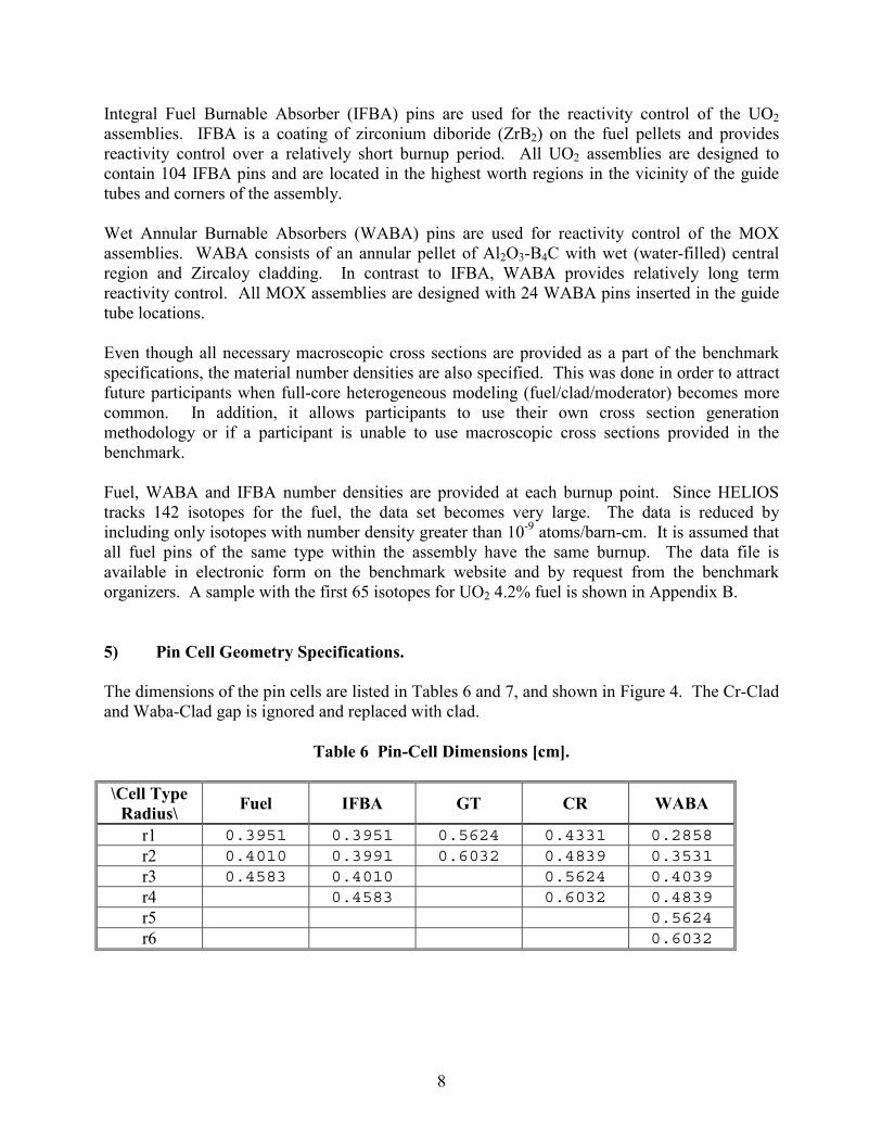
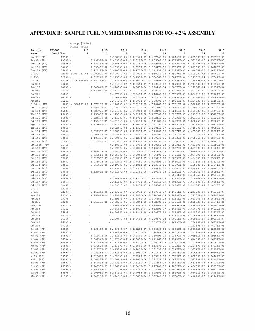
Integral Fuel Burnable Absorber (IFBA) pins are used for the reactivity control of the UO2 assemblies. IFBA is a coating of zirconium diboride (ZrB2) on the fuel pellets and provides reactivity control over a relatively short burnup period. All UO2 assemblies are designed to contain 104 IFBA pins and are located in the highest worth regions in the vicinity of the guide tubes and corners of the assembly. Wet Annular Burnable Absorbers (WABA) pins are used for reactivity control of the MOX assemblies. WABA consists of an annular pellet of Al2O3-B4C with wet (water-filled) central region and Zircaloy cladding. In contrast to IFBA, WABA provides relatively long term reactivity control. All MOX assemblies are designed with 24 WABA pins inserted in the guide tube locations. Even though all necessary macroscopic cross sections are provided as a part of the benchmark specifications, the material number densities are also specified. This was done in order to attract future participants when full-core heterogeneous modeling (fuel/clad/moderator) becomes more common. In addition, it allows participants to use their own cross section generation methodology or if a participant is unable to use macroscopic cross sections provided in the benchmark. Fuel, WABA and IFBA number densities are provided at each burnup point. Since HELIOS tracks 142 isotopes for the fuel, the data set becomes very large. The data is reduced by including only isotopes with number density greater than 10-9 atoms/barn-cm. It is assumed that all fuel pins of the same type within the assembly have the same burnup. The data file is available in electronic form on the benchmark website and by request from the benchmark organizers. A sample with the first 65 isotopes for UO2 4.2% fuel is shown in Appendix B. 5) Pin Cell Geometry Specifications. The dimensions of the pin cells are listed in Tables 6 and 7, and shown in Figure 4. The Cr-Clad and Waba-Clad gap is ignored and replaced with clad.
Table 6 Pin-Cell Dimensions [cm]. \Cell Type
Radius\ Fuel IFBA GT CR WABA
r1 0.3951 0.3951 0.5624 0.4331 0.2858 r2 0.4010 0.3991 0.6032 0.4839 0.3531 r3 0.4583 0.4010 0.5624 0.4039 r4 0.4583 0.6032 0.4839 r5 0.5624 r6 0.6032
9
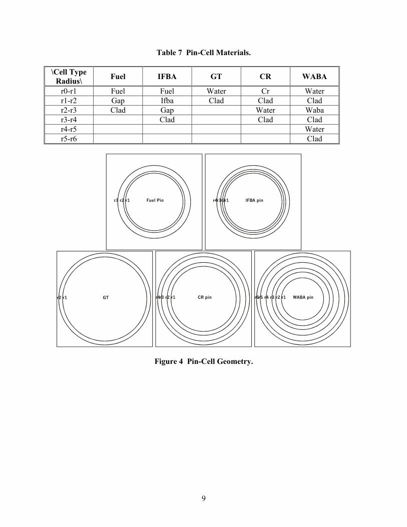
Table 7 Pin-Cell Materials. \Cell Type
Radius\ Fuel IFBA GT CR WABA
r0-r1 Fuel Fuel Water Cr Water r1-r2 Gap Ifba Clad Clad Clad r2-r3 Clad Gap Water Waba r3-r4 Clad Clad Clad r4-r5 Water r5-r6 Clad
Fuel Pinr1r2r3
IFBA pinr1r2r3r4
GTr1r2
CR pinr1r2r3r4
WABA pinr1r2r3r4r6r5
Figure 4 Pin-Cell Geometry.
10
6) Cross Section Modeling Information. The benchmark is intended as an assembly heterogeneous benchmark (cell-homogeneous or cell heterogeneous i.e. fuel/clad/moderator). However, it is assumed that not all participants have the same capabilities in their core simulators and that some participants might want to use different levels of homogenization detail. Therefore, the following XS homogenization levels and group structures are made available in the benchmark specifications:
• 2G assembly homogenized XS with discontinuity factors and pin power form functions • 4G assembly homogenized XS with discontinuity factors and pin power form functions • 8G pin-cell homogenized XS
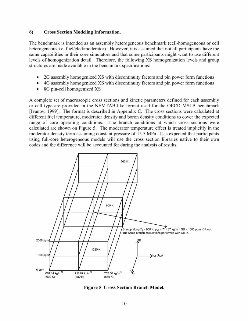
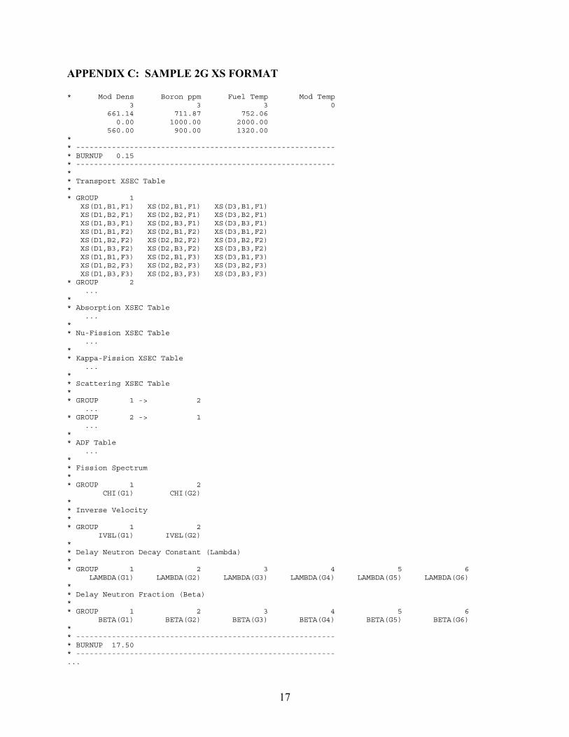
A complete set of macroscopic cross sections and kinetic parameters defined for each assembly or cell type are provided in the NEMTAB-like format used for the OECD MSLB benchmark [Ivanov, 1999]. The format is described in Appendix C. The cross sections were calculated at different fuel temperature, moderator density and boron density conditions to cover the expected range of core operating conditions. The branch conditions at which cross sections were calculated are shown on Figure 5. The moderator temperature effect is treated implicitly in the moderator density term assuming constant pressure of 15.5 MPa. It is expected that participants using full-core heterogeneous models will use the cross section libraries native to their own codes and the difference will be accounted for during the analysis of results.
Figure 5 Cross Section Branch Model.
11
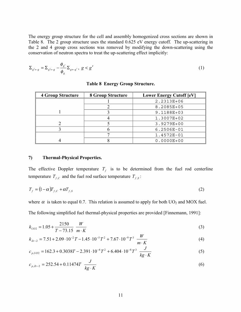
The energy group structure for the cell and assembly homogenized cross sections are shown in Table 8. The 2 group structure uses the standard 0.625 eV energy cutoff. The up-scattering in the 2 and 4 group cross sections was removed by modifying the down-scattering using the conservation of neutron spectra to treat the up-scattering effect implicitly:
ggg
ggggg ′←
′←′←′ Σ−Σ=Σ
φφ
, gg ′< (1)
Table 8 Energy Group Structure.
4 Group Structure 8 Group Structure Lower Energy Cutoff [eV]
1 2.2313E+06 2 8.2085E+05
1 3 9.1188E+03 4 1.3007E+02
2 5 3.9279E+00 3 6 6.2506E-01
7 1.4572E-01 4 8 0.0000E+00
7) Thermal-Physical Properties. The effective Doppler temperature fT is to be determined from the fuel rod centerline temperature CfT , and the fuel rod surface temperature SfT , :
( ) SfCff TTT ,,1 αα +−= (2) where α is taken to equal 0.7. This relation is assumed to apply for both UO2 and MOX fuel. The following simplified fuel thermal-physical properties are provided [Finnemann, 1991]:
15.73215005.12 −
+=T
kUO Km
W⋅
(3)
392522 1067.71045.11009.251.7 TTTkZr
−−−− ⋅+⋅−⋅+=
KmW⋅
(4)
38242, 10404.610391.23038.03.162 TTTc UOp
−− ⋅+⋅−+= KkgJ⋅
(5)
Tc Zrp 11474.054.2522, +=− KkgJ⋅
(6)
12
Since MOX fuel thermal conductivity is about 10% smaller than the UO2 fuel, for the purposes of the benchmark the MOX fuel thermal conductivity is calculated as:
29.0 UOMOX kk = (7) The heat transfer coefficient for the gap between fuel and cladding is assumed to be constant:
410=gaph Km
W⋅2 (8)
Expansion effects of fuel and cladding are not considered in this benchmark and are treated implicitly by providing fuel dimensions and densities at HFP conditions. The heat transfer coefficient between cladding and moderator should be calculated using code specific correlations. Because this is a very fast transient from hot zero power conditions, any variation in the manner of calculating these parameters should not be important for this benchmark. It is expected that the T/H feedback would be performed in a manner consistent with the neutronics model (e.g. pin-wise or assembly-wise) and any differences among participants will be accounted for in the analysis of results. 8) Benchmark Submittal. The submittal should be made on the Excel submittal templates that are part of the benchmark. If Excel is not available, other format will be provided by request. The submittal should be sent to both [email protected] and [email protected] by June 1, 2004. No paper copy is necessary. A benchmark website has been established at: https://engineering.purdue.edu/PARCS/MOX_Benchmark The website will make available the specifications, material number densities, cross section libraries, Excel submittal templates, answers to questions and any updates made since release of the benchmark. Organizers contact information:
Tomasz Kozlowski Purdue University
1290 Nuclear Engineering Building West Lafayette, IN 47907
U.S.A. [email protected] Tel. +1-765-494-7828 Fax. +1-765-494-9570
Prof. Thomas J. Downar Purdue University
1290 Nuclear Engineering Building West Lafayette, IN 47907
U.S.A. [email protected] Tel. +1-765-494-5752 Fax. +1-765-494-9570
Please notify benchmark organizers via email your intent to participate in the benchmark.
13
REFERENCES 1. A. A. Alsaed, M. L. Adams, “Disposition of Weapons-Grade Plutonium in Westinghouse Reactors,” ANRCP-1998-1, March 1998, http://www.pu.org/. 2. G. Alonso-Vargas, M. L. Adams, “Studies of Flexible MOX/LEU Fuel Cycles,” ORNL/SUB/99-19XSY062V-1, ANRCP-1999-9, March 1999, http://www.pu.org/. 3. N. Z. Cho, “Benchmark Problem 1A,” KAIST/NurapT, June 2000, http://nurapt.kaist.ac.kr/benchmark/. 4. H. Finnemann, A. Galati, “NEACRP 3-D LWR Core Transient Benchmark,” NEACRP-L-335, October 1991, http://www.nea.fr/html/science/docs/1991/. 5. J. C. Lefebvre, J. Mondot, J. P. West, “Benchmark Calculations of Power Distribution within Assemblies,” NEACRP L-336, October 1991, http://www.nea.fr/html/science/docs/1991/. 6. K. N. Ivanov, T. M. Beam, A. J. Baratta, “PWR Main Steam Line Break (MSLB) Benchmark, Volume I: Final Specifications,” NEA/NSC/DOC(99)8, April 1999, http://www.nea.fr/html/science/docs/1999/.
14
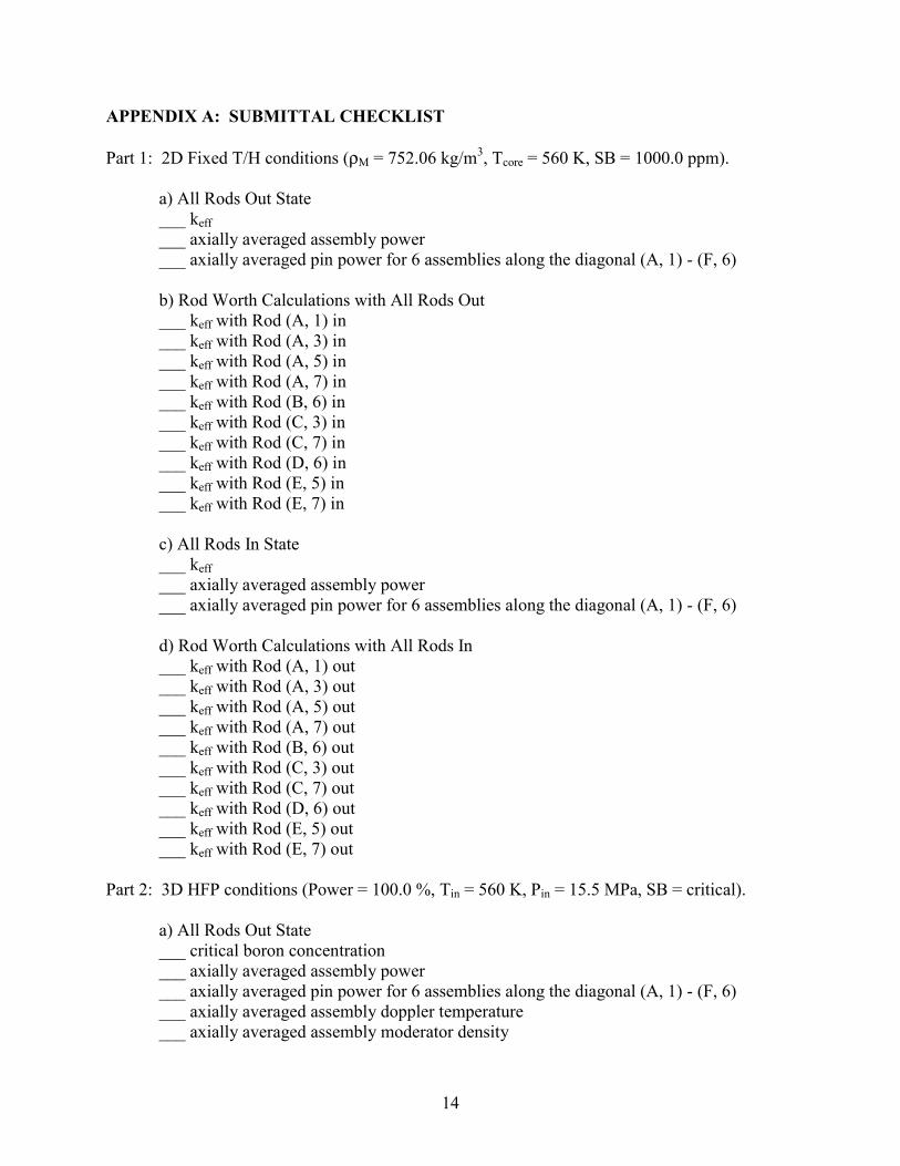
APPENDIX A: SUBMITTAL CHECKLIST Part 1: 2D Fixed T/H conditions (ρM = 752.06 kg/m3, Tcore = 560 K, SB = 1000.0 ppm). a) All Rods Out State ___ keff ___ axially averaged assembly power ___ axially averaged pin power for 6 assemblies along the diagonal (A, 1) - (F, 6) b) Rod Worth Calculations with All Rods Out ___ keff with Rod (A, 1) in ___ keff with Rod (A, 3) in ___ keff with Rod (A, 5) in ___ keff with Rod (A, 7) in ___ keff with Rod (B, 6) in ___ keff with Rod (C, 3) in ___ keff with Rod (C, 7) in ___ keff with Rod (D, 6) in ___ keff with Rod (E, 5) in ___ keff with Rod (E, 7) in c) All Rods In State ___ keff ___ axially averaged assembly power ___ axially averaged pin power for 6 assemblies along the diagonal (A, 1) - (F, 6) d) Rod Worth Calculations with All Rods In ___ keff with Rod (A, 1) out ___ keff with Rod (A, 3) out ___ keff with Rod (A, 5) out ___ keff with Rod (A, 7) out ___ keff with Rod (B, 6) out ___ keff with Rod (C, 3) out ___ keff with Rod (C, 7) out ___ keff with Rod (D, 6) out ___ keff with Rod (E, 5) out ___ keff with Rod (E, 7) out Part 2: 3D HFP conditions (Power = 100.0 %, Tin = 560 K, Pin = 15.5 MPa, SB = critical). a) All Rods Out State ___ critical boron concentration ___ axially averaged assembly power ___ axially averaged pin power for 6 assemblies along the diagonal (A, 1) - (F, 6) ___ axially averaged assembly doppler temperature ___ axially averaged assembly moderator density
15
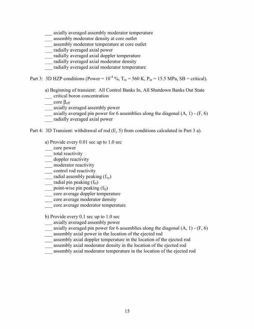
___ axially averaged assembly moderator temperature ___ assembly moderator density at core outlet ___ assembly moderator temperature at core outlet ___ radially averaged axial power ___ radially averaged axial doppler temperature ___ radially averaged axial moderator density ___ radially averaged axial moderator temperature Part 3: 3D HZP conditions (Power = 10-4 %, Tin = 560 K, Pin = 15.5 MPa, SB = critical). a) Beginning of transient: All Control Banks In, All Shutdown Banks Out State ___ critical boron concentration ___ core βeff ___ axially averaged assembly power ___ axially averaged pin power for 6 assemblies along the diagonal (A, 1) - (F, 6) ___ radially averaged axial power Part 4: 3D Transient: withdrawal of rod (E, 5) from conditions calculated in Part 3 a). a) Provide every 0.01 sec up to 1.0 sec ___ core power ___ total reactivity ___ doppler reactivity ___ moderator reactivity ___ control rod reactivity ___ radial assembly peaking (fxy) ___ radial pin peaking (fH) ___ point-wise pin peaking (fQ) ___ core average doppler temperature ___ core average moderator density ___ core average moderator temperature b) Provide every 0.1 sec up to 1.0 sec ___ axially averaged assembly power ___ axially averaged pin power for 6 assemblies along the diagonal (A, 1) - (F, 6) ___ assembly axial power in the location of the ejected rod ___ assembly axial doppler temperature in the location of the ejected rod ___ assembly axial moderator density in the location of the ejected rod ___ assembly axial moderator temperature in the location of the ejected rod
16
APPENDIX B: SAMPLE FUEL NUMBER DENSITIES FOR UO2 4.2% ASSEMBLY
Burnup [GWd/t]Burnup Point
Isotope HELIOS 0.0 0.15 17.5 20.0 22.5 32.5 35.0 37.5
Name Identifier 1 2 17 18 19 23 24 25
Mo-95 (FP) 42595 - - 1.76830E-05 2.10532E-05 2.43736E-05 3.70448E-05 4.00530E-05 4.29970E-05Tc-99 (FP) 43599 - 8.19239E-08 2.40933E-05 2.73519E-05 3.05554E-05 4.27999E-05 4.57139E-05 4.85671E-05
Pd-108 (FP) 46608 - 3.58133E-09 2.01585E-06 2.51039E-06 3.04915E-06 5.62129E-06 6.36298E-06 7.14199E-06Xe-131 (FP) 54631 - 1.63840E-08 1.06985E-05 1.20328E-05 1.33047E-05 1.77608E-05 1.87169E-05 1.96103E-05Cs-133 (FP) 55633 - 5.42128E-08 2.61076E-05 2.96475E-05 3.31193E-05 4.62932E-05 4.94008E-05 5.24312E-05U-235 92235 9.71492E-04 9.67328E-04 5.80775E-04 5.36589E-04 4.94761E-04 3.49384E-04 3.18203E-04 2.88980E-04
U-236 92236 - 7.92924E-07 7.11583E-05 7.86753E-05 8.56486E-05 1.08470E-04 1.12982E-04 1.17044E-04U-238 92238 2.18794E-02 2.18773E-02 2.16336E-02 2.15964E-02 2.15585E-02 2.13988E-02 2.13569E-02 2.13140E-02Pu-238 94238 - - 5.08451E-07 7.13536E-07 9.62084E-07 2.42733E-06 2.91468E-06 3.44917E-06Pu-239 94239 - 7.54884E-07 1.07858E-04 1.14067E-04 1.19049E-04 1.30075E-04 1.31236E-04 1.31952E-04
Pu-240 94240 - 1.43304E-09 2.21196E-05 2.60945E-05 3.00003E-05 4.43591E-05 4.75380E-05 5.05287E-05Pu-241 94241 - - 1.09779E-05 1.37246E-05 1.64876E-05 2.67336E-05 2.89421E-05 3.09761E-05Pu-242 94242 - - 1.26448E-06 1.86575E-06 2.60137E-06 6.85451E-06 8.22176E-06 9.69682E-06Am-241 95241 - - 1.76423E-07 2.49678E-07 3.33089E-07 7.19747E-07 8.17423E-07 9.11165E-07
O-16 in UO2 8001 4.57018E-02 4.57018E-02 4.57018E-02 4.57018E-02 4.57018E-02 4.57018E-02 4.57018E-02 4.57018E-02Ru-101 (FP) 44601 - 1.88143E-07 2.19801E-05 2.51017E-05 2.82139E-05 4.05465E-05 4.35951E-05 4.66278E-05Rh-103 (FP) 45603 - 4.02572E-09 1.19458E-05 1.37890E-05 1.55849E-05 2.22112E-05 2.37128E-05 2.51478E-05Rh-105 (FP) 45605 - 1.75909E-08 4.57383E-08 4.84212E-08 5.09780E-08 6.02870E-08 6.24351E-08 6.45223E-08
Pd-105 (FP) 46605 - 2.02417E-08 7.71152E-06 9.18176E-06 1.07211E-05 1.74893E-05 1.93171E-05 2.11929E-05Pd-107 (FP) 46607 - 8.43945E-09 3.32193E-06 4.08714E-06 4.91198E-06 8.76228E-06 9.85276E-06 1.09907E-05Ag-109 (FP) 47609 - 2.12441E-09 1.21185E-06 1.49268E-06 1.79259E-06 3.14995E-06 3.52120E-06 3.90237E-06In-115 (FP) 49615 - - 9.92244E-08 1.11432E-07 1.23041E-07 1.63316E-07 1.71839E-07 1.79758E-07
Xe-134 (FP) 54634 - 2.82190E-07 3.25852E-05 3.71928E-05 4.17910E-05 6.00974E-05 6.46538E-05 6.92024E-05Nd-143 (FP) 60643 - 9.00163E-09 1.97780E-05 2.21845E-05 2.44529E-05 3.21512E-05 3.37326E-05 3.51775E-05Nd-145 (FP) 60645 - 1.40715E-07 1.48964E-05 1.68123E-05 1.86793E-05 2.56639E-05 2.72896E-05 2.88670E-05Pm-147 (FP) 61647 - 9.51027E-09 5.80911E-06 6.27491E-06 6.67053E-06 7.69046E-06 7.83361E-06 7.94163E-06
Pm-148m (FP) 61748 - - 4.84864E-08 5.24076E-08 5.56855E-08 6.35934E-08 6.45369E-08 6.51599E-08Sm-147 (FP) 62647 - - 1.00999E-06 1.25728E-06 1.51371E-06 2.55676E-06 2.80709E-06 3.04864E-06Sm-149 (FP) 62649 - 1.46942E-08 1.07522E-07 1.08046E-07 1.08134E-07 1.05255E-07 1.03964E-07 1.02526E-07Sm-150 (FP) 62650 - 2.73051E-09 5.08532E-06 5.89284E-06 6.70640E-06 9.97015E-06 1.07769E-05 1.15757E-05
Sm-151 (FP) 62651 - 9.61655E-09 4.32940E-07 4.51705E-07 4.69311E-07 5.30339E-07 5.43485E-07 5.55867E-07Sm-152 (FP) 62652 - 1.03882E-08 2.39241E-06 2.71748E-06 3.02869E-06 4.14660E-06 4.39754E-06 4.63829E-06Eu-153 (FP) 63653 - 2.96560E-09 1.51938E-06 1.85186E-06 2.20324E-06 3.73578E-06 4.13668E-06 4.53971E-06Eu-154 (FP) 63654 - - 2.17340E-07 2.85195E-07 3.61079E-07 7.25940E-07 8.27219E-07 9.30400E-07
Eu-155 (FP) 63655 - 1.32483E-09 4.96168E-08 6.03234E-08 7.23063E-08 1.31119E-07 1.47925E-07 1.65291E-07Gd-155 (FP) 64655 - - - - - 1.20544E-09 1.35055E-09 1.49818E-09Gd-156 (FP) 64656 - - 4.79685E-07 6.23822E-07 7.95778E-07 1.83527E-06 2.20096E-06 2.61565E-06Gd-157 (FP) 64657 - - 2.01182E-09 2.21770E-09 2.43171E-09 3.40132E-09 3.67750E-09 3.96851E-09
Gd-158 (FP) 64658 - - 1.58331E-07 1.96743E-07 2.39588E-07 4.62939E-07 5.34135E-07 6.12592E-07U-234 92234 - - - - - - - -U-237 92237 - 8.46214E-09 1.43301E-07 1.56299E-07 1.68754E-07 2.14061E-07 2.24390E-07 2.34336E-07Np-237 93237 - 1.85389E-09 3.69536E-06 4.49683E-06 5.33400E-06 8.88982E-06 9.79707E-06 1.06995E-05
Np-238 93238 - - 9.14987E-09 1.13638E-08 1.37685E-08 2.51144E-08 2.83325E-08 3.16794E-08Np-239 93239 - 1.06838E-06 1.62883E-06 1.65984E-06 1.69260E-06 1.83717E-06 1.87603E-06 1.91571E-06Am-242m 95342 - - 2.66668E-09 3.97286E-09 5.51556E-09 1.30393E-08 1.49824E-08 1.68500E-08Am-243 95243 - - 1.08442E-07 1.85480E-07 2.94289E-07 1.14358E-06 1.47677E-06 1.86212E-06
Cm-242 96242 - - 2.60826E-08 4.18494E-08 6.23897E-08 1.91794E-07 2.34309E-07 2.79774E-07Cm-243 96243 - - - - - 3.13637E-09 4.14652E-09 5.32356E-09Cm-244 96244 - - 1.20043E-08 2.40266E-08 4.39017E-08 2.70011E-07 3.83945E-07 5.30227E-07Cm-245 96245 - - - - 1.35307E-09 1.16135E-08 1.75815E-08 2.56871E-08
Cm-246 96246 - - - - - - 1.19368E-09 1.94276E-09Br-81 (FP) 35581 - 7.19542E-09 8.03959E-07 9.12825E-07 1.02009E-06 1.43280E-06 1.53182E-06 1.62918E-06Kr-82 (FP) 36582 - - 8.44430E-09 1.09770E-08 1.38494E-08 2.88013E-08 3.34192E-08 3.83934E-08Kr-83 (FP) 36583 - 1.91147E-08 1.85164E-06 2.06244E-06 2.26079E-06 2.93190E-06 3.06961E-06 3.19551E-06
Kr-84 (FP) 36584 - 3.58234E-08 3.93700E-06 4.47587E-06 5.01116E-06 7.12403E-06 7.64665E-06 8.16751E-06Kr-85 (FP) 36585 - 9.91486E-09 9.86750E-07 1.10570E-06 1.22003E-06 1.63430E-06 1.72780E-06 1.81750E-06Kr-86 (FP) 36586 - 6.93053E-08 7.13350E-06 8.03551E-06 8.91357E-06 1.22023E-05 1.29717E-05 1.37211E-05Sr-89 (FP) 38589 - 1.61277E-07 2.41539E-06 2.34747E-06 2.28103E-06 2.03479E-06 1.97747E-06 1.92157E-06
Sr-90 (FP) 38590 - 2.02118E-07 2.03192E-05 2.28109E-05 2.52173E-05 3.40448E-05 3.60634E-05 3.80106E-05Y-89 (FP) 39589 - 4.51067E-09 1.45298E-05 1.67222E-05 1.88521E-05 2.67821E-05 2.86255E-05 3.04162E-05Y-91 (FP) 39591 - 2.00633E-07 3.55081E-06 3.46700E-06 3.38252E-06 3.06275E-06 2.98793E-06 2.91497E-06Zr-91 (FP) 40591 - 4.84189E-09 1.77237E-05 2.05119E-05 2.32316E-05 3.34443E-05 3.58388E-05 3.81729E-05
Zr-93 (FP) 40593 - 2.24830E-07 2.39695E-05 2.71046E-05 3.01778E-05 4.18822E-05 4.46669E-05 4.73970E-05Zr-95 (FP) 40595 - 2.25745E-07 4.80109E-06 4.75775E-06 4.70800E-06 4.50053E-06 4.45032E-06 4.40110E-06Zr-96 (FP) 40596 - 2.27071E-07 2.51684E-05 2.85976E-05 3.19918E-05 4.52378E-05 4.84704E-05 5.16727E-05Nb-95 (FP) 41595 - 4.84915E-09 2.62471E-06 2.61063E-06 2.58774E-06 2.47646E-06 2.44870E-06 2.42142E-06
17
APPENDIX C: SAMPLE 2G XS FORMAT * Mod Dens Boron ppm Fuel Temp Mod Temp 3 3 3 0 661.14 711.87 752.06 0.00 1000.00 2000.00 560.00 900.00 1320.00 * * ---------------------------------------------------------- * BURNUP 0.15 * ---------------------------------------------------------- * * Transport XSEC Table * * GROUP 1 XS(D1,B1,F1) XS(D2,B1,F1) XS(D3,B1,F1) XS(D1,B2,F1) XS(D2,B2,F1) XS(D3,B2,F1) XS(D1,B3,F1) XS(D2,B3,F1) XS(D3,B3,F1) XS(D1,B1,F2) XS(D2,B1,F2) XS(D3,B1,F2) XS(D1,B2,F2) XS(D2,B2,F2) XS(D3,B2,F2) XS(D1,B3,F2) XS(D2,B3,F2) XS(D3,B3,F2) XS(D1,B1,F3) XS(D2,B1,F3) XS(D3,B1,F3) XS(D1,B2,F3) XS(D2,B2,F3) XS(D3,B2,F3) XS(D1,B3,F3) XS(D2,B3,F3) XS(D3,B3,F3) * GROUP 2 ... * * Absorption XSEC Table ... * * Nu-Fission XSEC Table ... * * Kappa-Fission XSEC Table ... * * Scattering XSEC Table * * GROUP 1 -> 2 ... * GROUP 2 -> 1 ... * * ADF Table ... * * Fission Spectrum * * GROUP 1 2 CHI(G1) CHI(G2) * * Inverse Velocity * * GROUP 1 2 IVEL(G1) IVEL(G2) * * Delay Neutron Decay Constant (Lambda) * * GROUP 1 2 3 4 5 6 LAMBDA(G1) LAMBDA(G2) LAMBDA(G3) LAMBDA(G4) LAMBDA(G5) LAMBDA(G6) * * Delay Neutron Fraction (Beta) * * GROUP 1 2 3 4 5 6 BETA(G1) BETA(G2) BETA(G3) BETA(G4) BETA(G5) BETA(G6) * * ---------------------------------------------------------- * BURNUP 17.50 * ---------------------------------------------------------- ...

18
APPENDIX D: DETAILS TO BE PROVIDED ABOUT THE CALCULATION SCHEME 1. Name and address of participant(s). 2. Establishment(s). 3. Name of code system(s) and computational method, angular and spatial approximation used. 4. Bibliographical references for the code. 5. Cross section library used. If own library was used, please describe homogenization method, number of groups and data reduction method. 6. Other assumptions and comments useful for interpreting correctly the results. Provide short description of the T/H solution.