Embed Size (px)
Citation preview
1
O li D t C tOversampling Data ConvertersTuesday, March 15th, 9:15 – 11:40
Snorre Aunet ([email protected])
Nanoelectronics group
Department of Informatics
University of Oslo
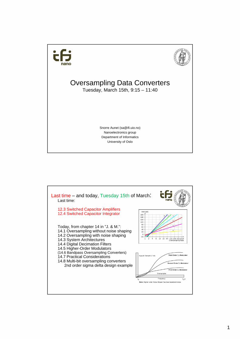
Last time – and today, Tuesday 15th of March:Last time:
12.3 Switched Capacitor Amplifiers12.4 Switched Capacitor Integrator
Today, from chapter 14 in ”J. & M.”:14.1 Oversampling without noise shaping14.2 Oversampling with noise shaping14.3 System Architectures14.4 Digital Decimation Filters14.5 Higher-Order Modulators(14.6 Bandpass Oversampling Converters)14.7 Practical Considerations14.8 Multi-bit oversampling converters
2nd order sigma delta design example
2
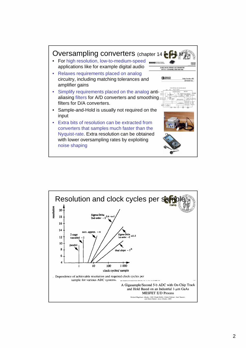
Oversampling converters (chapter 14 in ”J & M”)• For high resolution, low-to-medium-speed
applications like for example digital audio
• Relaxes requirements placed on analog circuitry, including matching tolerances and amplifier gains
• Simplify requirements placed on the analog anti-aliasing filters for A/D converters and smoothing filters for D/A converters.
• Sample-and-Hold is usually not required on the input
• Extra bits of resolution can be extracted from converters that samples much faster than the Nyquist-rate. Extra resolution can be obtained with lower oversampling rates by exploiting noise shaping
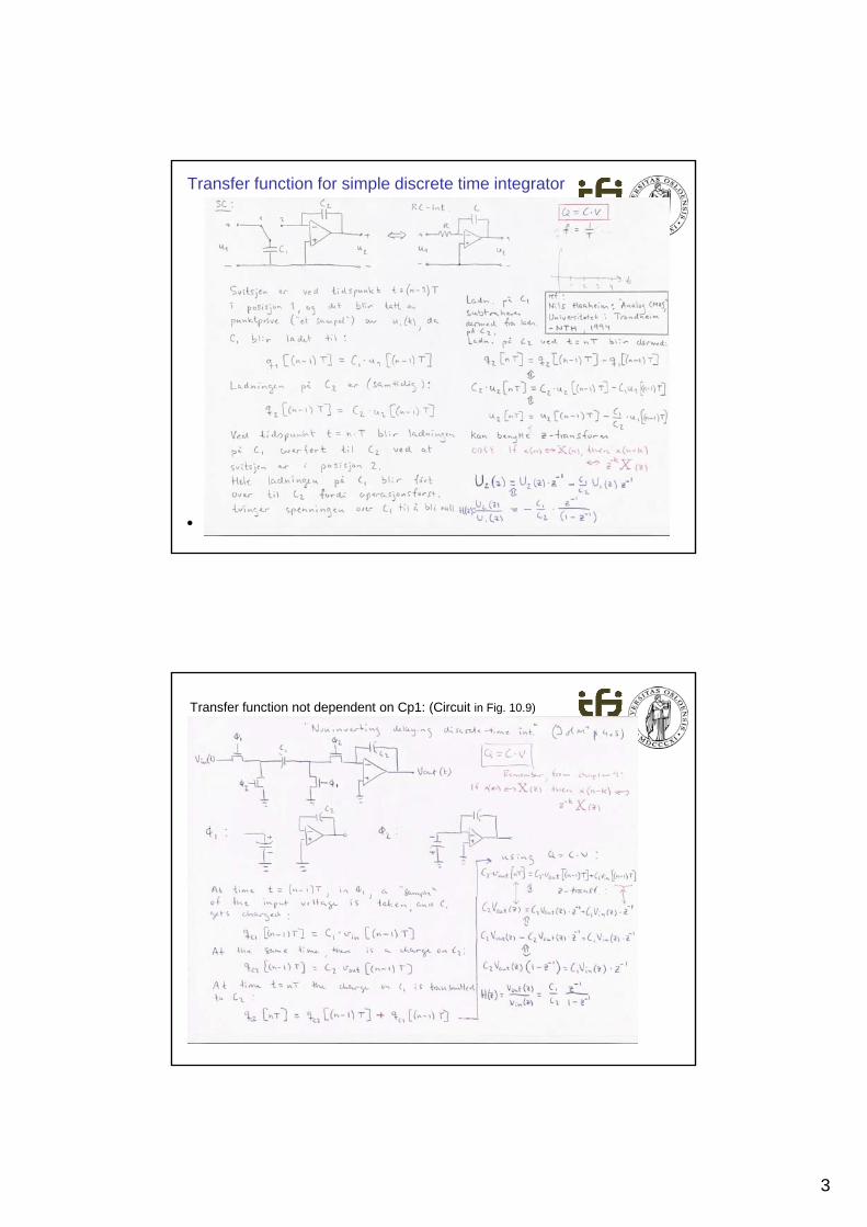
Resolution and clock cycles per sample
3
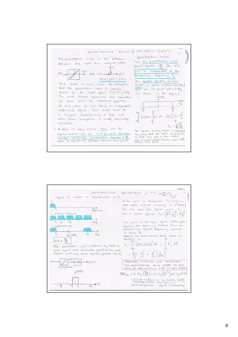
Transfer function for simple discrete time integrator
•
Transfer function not dependent on Cp1: (Circuit in Fig. 10.9)
4
5
15. mars 2011
9
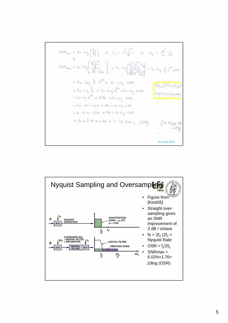
Nyquist Sampling and Oversampling
• Figure from [Kest05]
• Straight over-sampling givesan SNR improvement of3 dB / octave
• fs > 2f0 (2f0 = Nyquist Rate
• OSR = f /2f• OSR = fs/2f0• SNRmax =
6.02N+1.76+
10log (OSR)
6
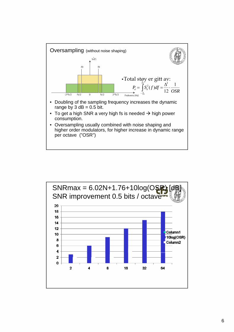
Oversampling (without noise shaping)
Se(f )2
-f0 f0
•Total støy er gitt av:
• Doubling of the sampling frequency increases the dynamic range by 3 dB = 0.5 bit.
• To get a high SNR a very high fs is needed high power
OSRdffSP
f
f
ee
1
12)(
22
0
0
-fs/2-2*fs/2 fs/2 2*fs/20 Frekvens (Hz)
•Total støy er gitt av:
To get a high SNR a very high fs is needed high power consumption.
• Oversampling usually combined with noise shaping and higher order modulators, for higher increase in dynamic range per octave (”OSR”)
SNRmax = 6.02N+1.76+10log(OSR) [dB] SNR improvement 0.5 bits / octave
7
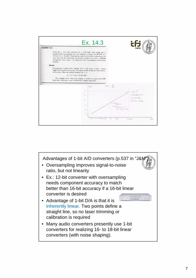
Ex. 14.3
Advantages of 1-bit A/D converters (p.537 in ”J&M”)
• Oversampling improves signal-to-noiseratio, but not linearity
• Ex.: 12-bit converter with oversampling needs component acc rac to matchneeds component accuracy to match better than 16-bit accuracy if a 16-bit linear converter is desired
• Advantage of 1-bit D/A is that it is inherently linear. Two points define a straight line so no laser trimming orstraight line, so no laser trimming or calibration is required
• Many audio converters presently use 1-bit converters for realizing 16- to 18-bit linear converters (with noise shaping).
8
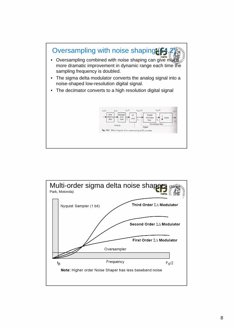
Oversampling with noise shaping (14.2)• Oversampling combined with noise shaping can give much
more dramatic improvement in dynamic range each time the sampling frequency is doubled.
• The sigma delta modulator converts the analog signal into a• The sigma delta modulator converts the analog signal into a noise-shaped low-resolution digital signal.
• The decimator converts to a high resolution digital signal
Multi-order sigma delta noise shapers (Sangil
Park, Motorola)
9
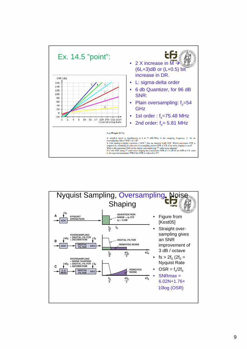
Ex. 14.5 ”point”:• 2 X increase in M
(6L+3)dB or (L+0.5) bit increase in DR.
• L: sigma-delta orderL: sigma delta order
• 6 db Quantizer, for 96 dB SNR:
• Plain oversampling: fs=54 GHz
• 1st order : fs=75.48 MHz
• 2nd order: fs= 5.81 MHz
• Exam problem (INF4420) below
15. mars 2011
17
Nyquist Sampling, Oversampling, Noise Shaping
• Figure from [Kest05]
• Straight over• Straight over-sampling givesan SNR improvement of3 dB / octave
• fs > 2f0 (2f0 = Nyquist Rate
• OSR = fs/2f0• SNRmax =
6.02N+1.76+
10log (OSR)
10
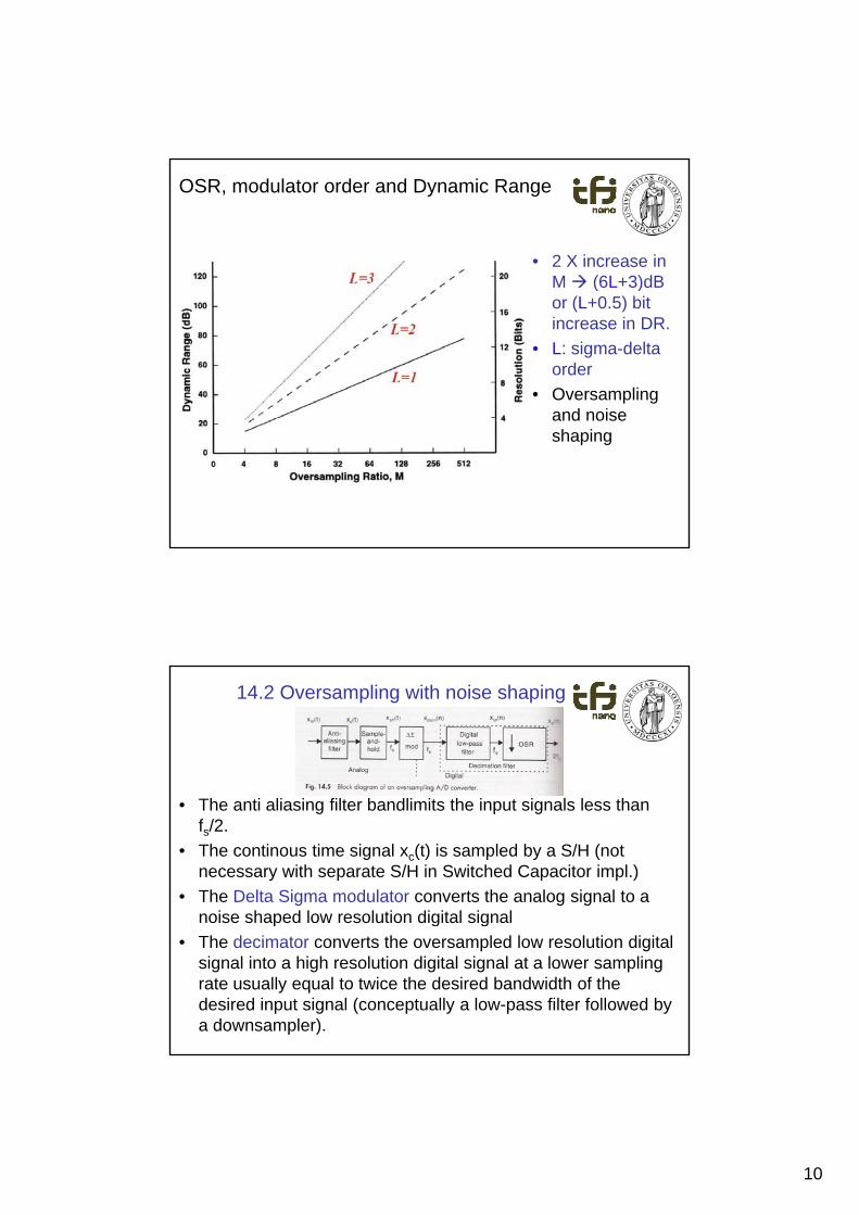
OSR, modulator order and Dynamic Range
• 2 X increase in M (6L+3)dB ( )or (L+0.5) bit increase in DR.
• L: sigma-deltaorder
• Oversampling and noiseand noiseshaping
14.2 Oversampling with noise shaping
• The anti aliasing filter bandlimits the input signals less than fs/2.
• The continous time signal xc(t) is sampled by a S/H (not necessary with separate S/H in Switched Capacitor impl.)
• The Delta Sigma modulator converts the analog signal to a noise shaped low resolution digital signalp g g
• The decimator converts the oversampled low resolution digital signal into a high resolution digital signal at a lower sampling rate usually equal to twice the desired bandwidth of the desired input signal (conceptually a low-pass filter followed by a downsampler).
11
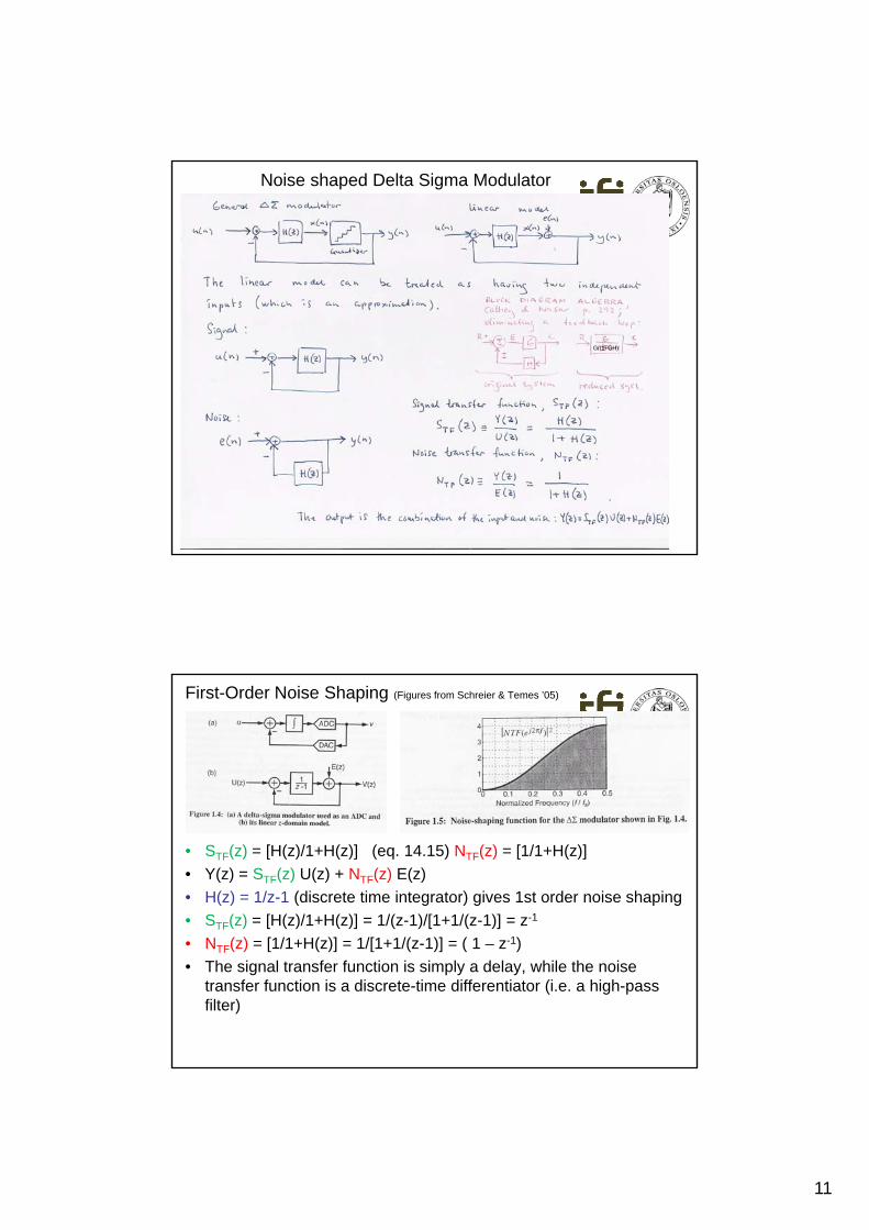
Noise shaped Delta Sigma Modulator
G/(1 GH)
±
First-Order Noise Shaping (Figures from Schreier & Temes ’05)
• STF(z) = [H(z)/1+H(z)] (eq. 14.15) NTF(z) = [1/1+H(z)]
• Y(z) = STF(z) U(z) + NTF(z) E(z)
• H(z) = 1/z-1 (discrete time integrator) gives 1st order noise shaping
• STF(z) = [H(z)/1+H(z)] = 1/(z-1)/[1+1/(z-1)] = z-1
1• NTF(z) = [1/1+H(z)] = 1/[1+1/(z-1)] = ( 1 – z-1)
• The signal transfer function is simply a delay, while the noise transfer function is a discrete-time differentiator (i.e. a high-pass filter)
12
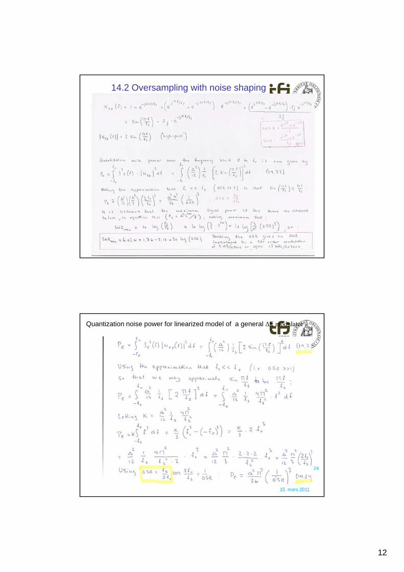
14.2 Oversampling with noise shaping
Quantization noise power for linearized model of a general ΔΣ modulator
15. mars 2011
24
13
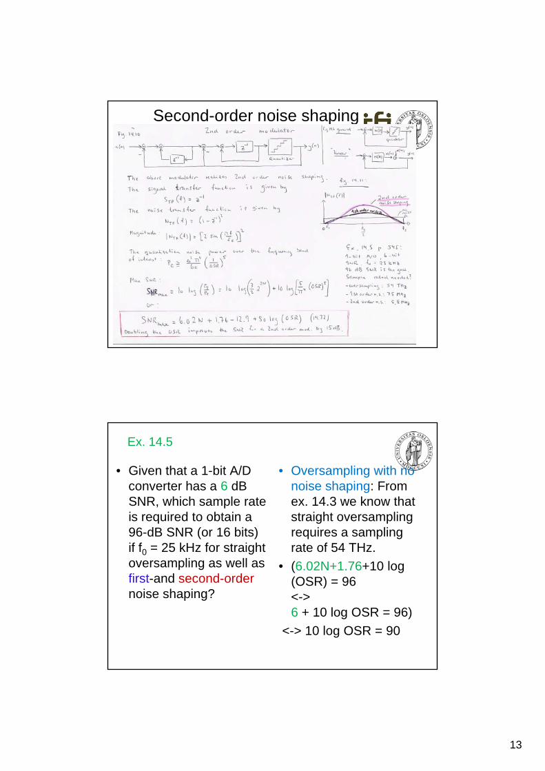
Second-order noise shaping
Ex. 14.5
• Given that a 1-bit A/D converter has a 6 dB SNR, which sample rate
• Oversampling with no noise shaping: From ex. 14.3 we know thatSNR, which sample rate
is required to obtain a 96-dB SNR (or 16 bits) if f0 = 25 kHz for straight oversampling as well as first-and second-order
ex. 14.3 we know that straight oversampling requires a sampling rate of 54 THz.
• (6.02N+1.76+10 log (OSR) = 96
noise shaping?( )<-> 6 + 10 log OSR = 96)
<-> 10 log OSR = 90
14
Ex. 14.5
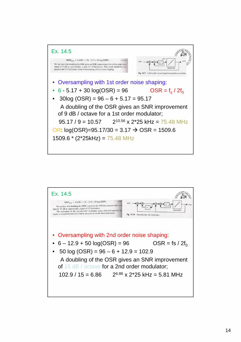
Oversampling with 1st order noise shaping:• Oversampling with 1st order noise shaping:
• 6 - 5.17 + 30 log(OSR) = 96 OSR = fs / 2f0• 30log (OSR) = 96 – 6 + 5.17 = 95.17
A doubling of the OSR gives an SNR improvementof 9 dB / octave for a 1st order modulator;
95.17 / 9 = 10.57 210.56 x 2*25 kHz = 75.48 MHz
OR: log(OSR)=95.17/30 = 3.17 OSR = 1509.6
1509.6 * (2*25kHz) = 75.48 MHz
Ex. 14.5
• Oversampling with 2nd order noise shaping:
• 6 – 12.9 + 50 log(OSR) = 96 OSR = fs / 2f0• 50 log (OSR) = 96 – 6 + 12.9 = 102.9
A doubling of the OSR gives an SNR improvementA doubling of the OSR gives an SNR improvementof 15 dB / octave for a 2nd order modulator;
102.9 / 15 = 6.86 26.86 x 2*25 kHz = 5.81 MHz
15
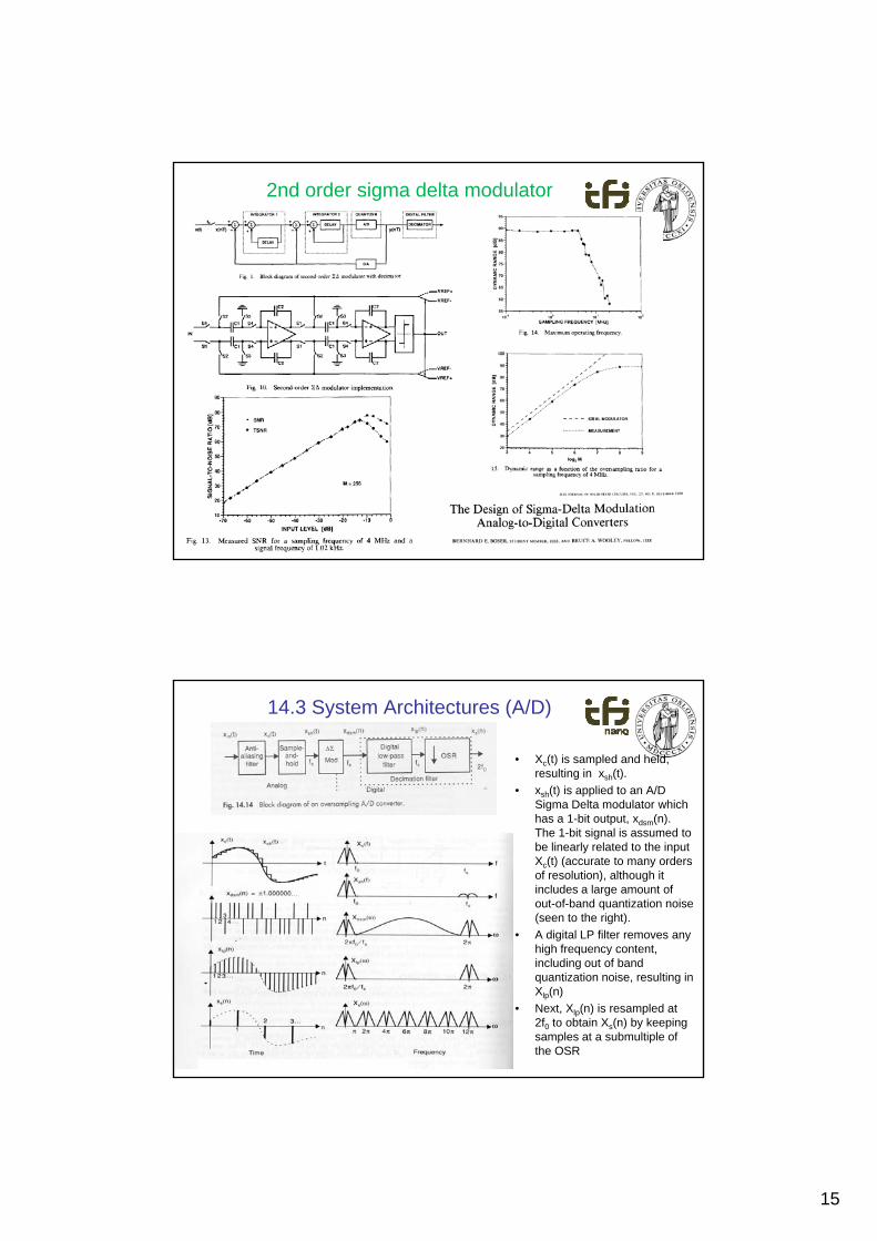
2nd order sigma delta modulator
14.3 System Architectures (A/D)
• Xc(t) is sampled and held, resulting in xsh(t).
• xsh(t) is applied to an A/D Sigma Delta modulator whichhas a 1-bit output, xdsm(n). The 1-bit signal is assumed to be linearly related to the input Xc(t) (accurate to many ordersof resolution), although it includes a large amount ofout-of-band quantization noise(seen to the right).
• A digital LP filter removes anyhi h f t thigh frequency content, including out of band quantization noise, resulting in Xlp(n)
• Next, Xlp(n) is resampled at 2f0 to obtain Xs(n) by keepingsamples at a submultiple ofthe OSR
16
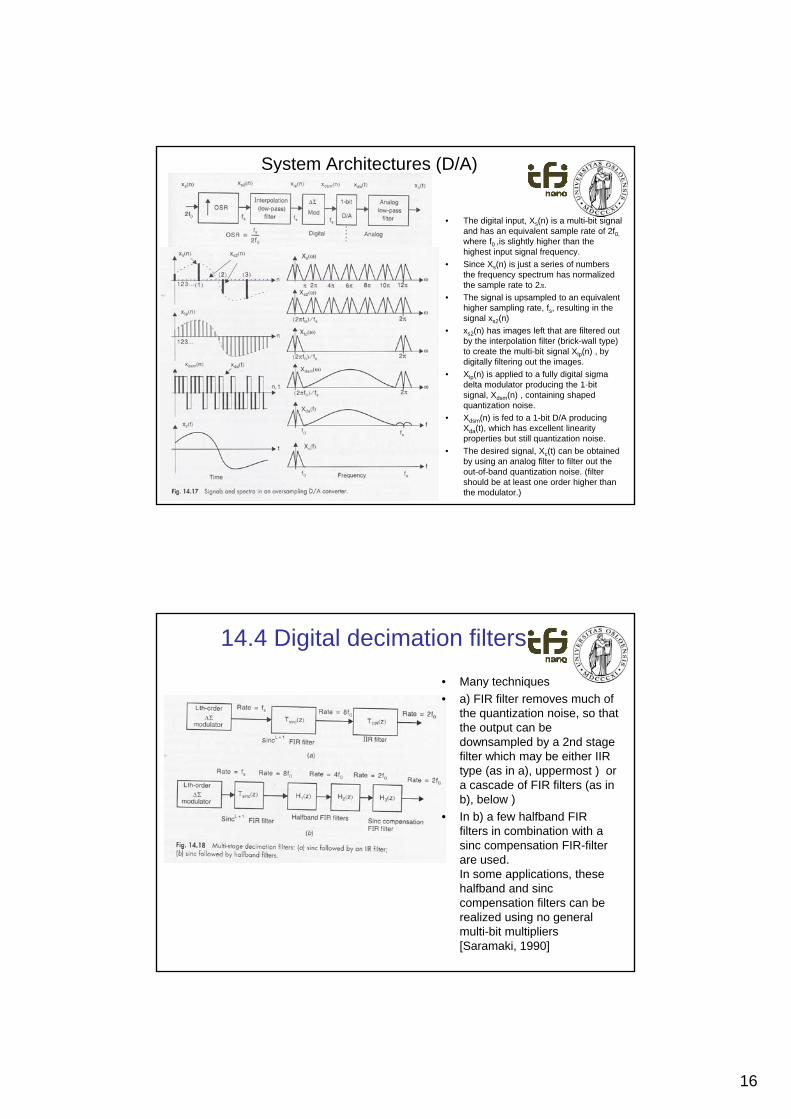
System Architectures (D/A)
• The digital input, Xs(n) is a multi-bit signal and has an equivalent sample rate of 2f0,
where f0 ,is slightly higher than thehighest input signal frequency.
• Since X (n) is just a series of numbersSince Xs(n) is just a series of numbersthe frequency spectrum has normalizedthe sample rate to 2л.
• The signal is upsampled to an equivalenthigher sampling rate, fs, resulting in thesignal xs2(n)
• xs2(n) has images left that are filtered outby the interpolation filter (brick-wall type) to create the multi-bit signal Xlp(n) , by digitally filtering out the images.
• Xlp(n) is applied to a fully digital sigma delta modulator producing the 1-bitdelta modulator producing the 1 bit signal, Xdsm(n) , containing shapedquantization noise.
• Xdsm(n) is fed to a 1-bit D/A producingXda(t), which has excellent linearityproperties but still quantization noise.
• The desired signal, Xc(t) can be obtainedby using an analog filter to filter out theout-of-band quantization noise. (filter should be at least one order higher thanthe modulator.)
14.4 Digital decimation filters
• Many techniques
• a) FIR filter removes much ofthe quantization noise, so thatthe output can be pdownsampled by a 2nd stage filter which may be either IIR type (as in a), uppermost ) or a cascade of FIR filters (as in b), below )
• In b) a few halfband FIR filters in combination with a sinc compensation FIR-filterare used. In some applications, thesehalfband and sinccompensation filters can be realized using no general multi-bit multipliers[Saramaki, 1990]
17
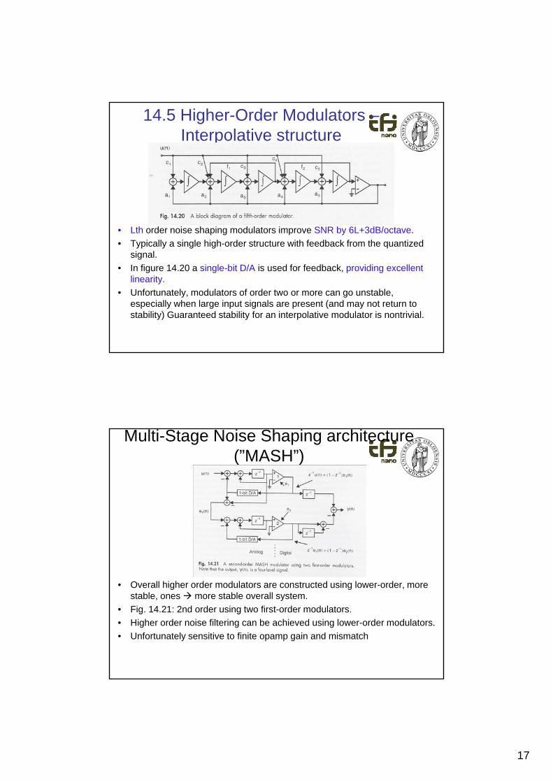
14.5 Higher-Order Modulators –Interpolative structure
• Lth order noise shaping modulators improve SNR by 6L+3dB/octave.
• Typically a single high-order structure with feedback from the quantized signal.
• In figure 14 20 a single-bit D/A is used for feedback providing excellentIn figure 14.20 a single bit D/A is used for feedback, providing excellent linearity.
• Unfortunately, modulators of order two or more can go unstable, especially when large input signals are present (and may not return to stability) Guaranteed stability for an interpolative modulator is nontrivial.
Multi-Stage Noise Shaping architecture (”MASH”)
• Overall higher order modulators are constructed using lower-order, more stable ones more stable overall systemstable, ones more stable overall system.
• Fig. 14.21: 2nd order using two first-order modulators.
• Higher order noise filtering can be achieved using lower-order modulators.
• Unfortunately sensitive to finite opamp gain and mismatch
18
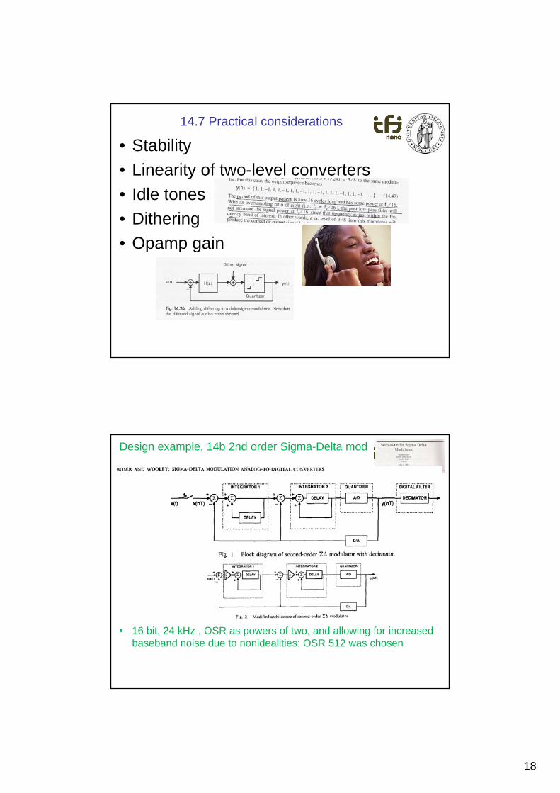
14.7 Practical considerations
• Stability
• Linearity of two-level converters
Idl t• Idle tones
• Dithering
• Opamp gain
Design example, 14b 2nd order Sigma-Delta mod
• 16 bit, 24 kHz , OSR as powers of two, and allowing for increased baseband noise due to nonidealities: OSR 512 was chosen
19
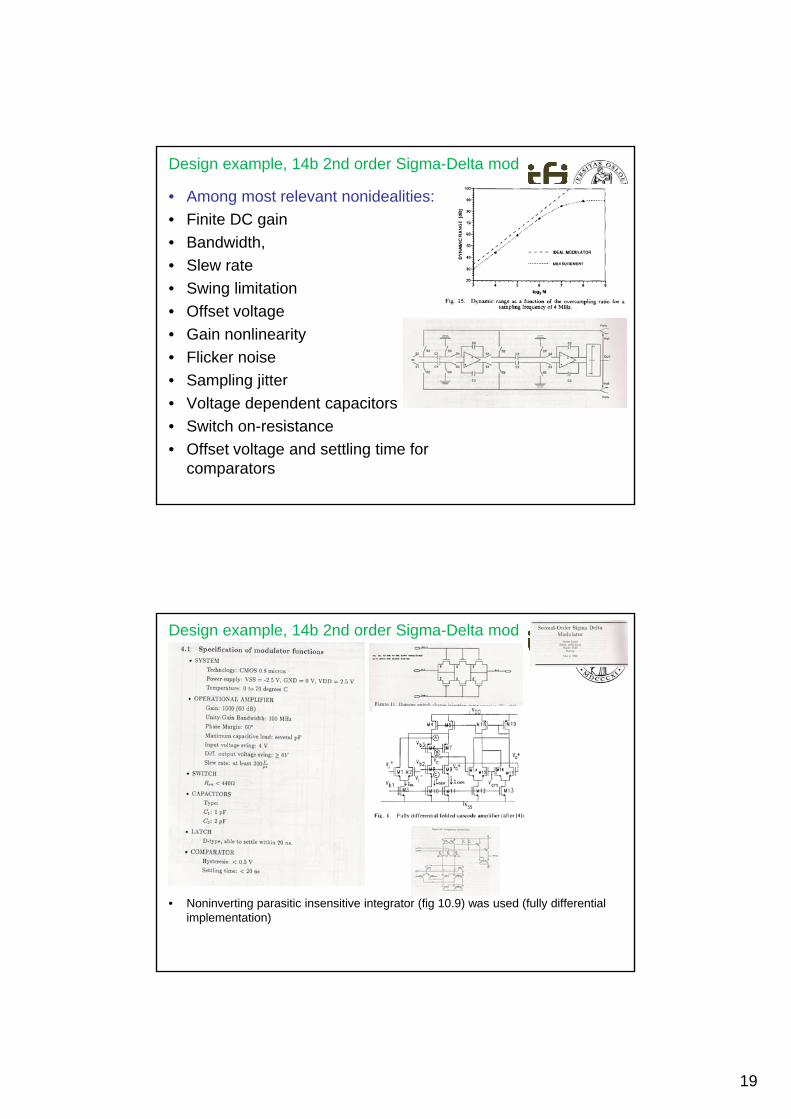
Design example, 14b 2nd order Sigma-Delta mod
• Among most relevant nonidealities:
• Finite DC gain
• Bandwidth,
• Slew rate• Slew rate
• Swing limitation
• Offset voltage
• Gain nonlinearity
• Flicker noise
• Sampling jitterSa p g j e
• Voltage dependent capacitors
• Switch on-resistance
• Offset voltage and settling time for comparators
Design example, 14b 2nd order Sigma-Delta mod
• Noninverting parasitic insensitive integrator (fig 10.9) was used (fully differential implementation)
20
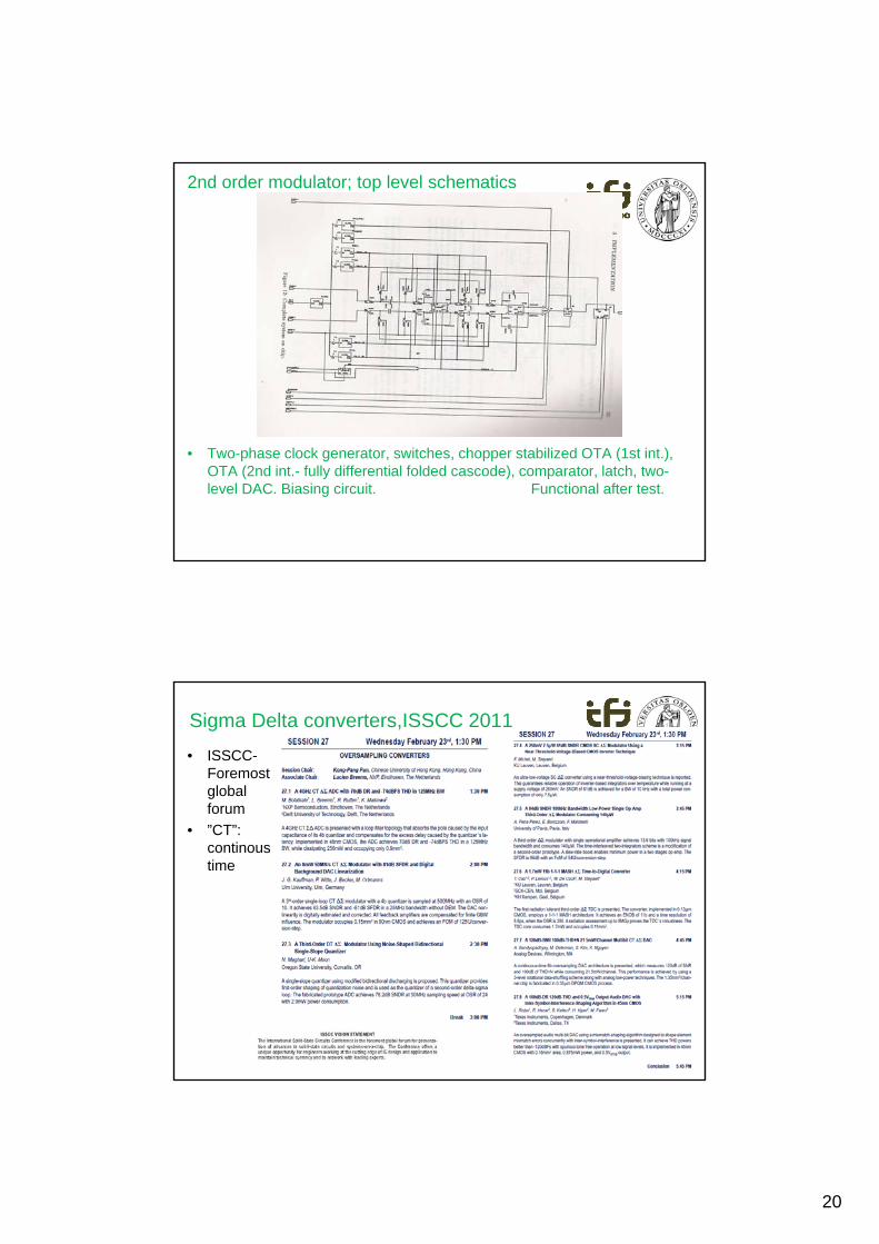
2nd order modulator; top level schematics
• Two-phase clock generator, switches, chopper stabilized OTA (1st int.), OTA (2nd int.- fully differential folded cascode), comparator, latch, two-level DAC. Biasing circuit. Functional after test.
Sigma Delta converters,ISSCC 2011
• ISSCC-Foremost global forum
• ”CT”: continoustime

21
litterature• David A. Johns, Ken Martin: ”Analog Integrated Circuit Design”, Wiley, ISBN 0-471-14448-7.
• Stanley P. Lipshitz, John Vanderkooy: Why 1-bit Sigma Delta Conversion is Unsuitable for High QualityApplications , Journal of the audio engineering society, 2001.
• Y. Chiu, B. Nicolic, P. R. Gray: Scaling of Analog-to-Digital Converters into Ultra-Deep-SubmicronCMOS, Proceedings of Custom Integrated Circuits Conference, 2005., g g ,
• Richard Hagelauer, Frank Oehler, Gunther Rohmer, Josef Sauerer, Dieter Seitzer: A GigaSample/Second 5-b ADC with On-Chip Track-And-Hold Based on an Industrial 1 um GaAsMESFET E/D Process, IEEE Journal of Solid-State Circuits (”JSSC”), October 1992.
• Walt Kester: Which ADC Architecture is right for your application?, Analog Dialogue, Analog Devices, 2005.
• Richard Lyons, Randy Yates: ”Reducing ADC Quantization Noise”, MicroWaves & RF, 2005
• Sangil Park: ”Principles of sigma-delta modulators for analog to digital converters”, Motorola
• B. E. Boser, B. A. Wooley: ”The design of sigma delta modulation analog to digital converters, IEEE JSSC, 1988.
J h P B tl P i i l f M t S t 2 d d B tl 1989• John P. Bentley: Principles of Measurement Systems, 2nd ed., Bentley, 1989.
Next week, 22/3-11:
• Ch. 13; Nonlinearity and Mismatch plus beginning of
chapter 14; Oscillators (?)• Messages are given on the INF4420 homepage.
• [email protected] , 22852703 / 90013264
22
15. mars 2011
43