Embed Size (px)
DESCRIPTION
AISC paper
Citation preview
Shear Strength of Stud Connectors in Lightweightand Normal-Weight Concrete
JORGEN G. OLLGAARD, ROGER G. SLUTTER AND JOHN W. FISHER
STEEL-CONCRETE composite construction using normal-weight concrete has been used since early in the 1920's.Substantial use of composite construction began mainly forbridge structures in the 1950's as a result of the work done byViest.16-18 Its primary growth in building construction duringthe last decade was a result of the simplified designprovisions introduced into the 1961 AISC Specification. Thedevelopment of these provisions were based on studiesreported by Slutter and Driscoll.5,11
The type of shear connectors has changed substantiallyduring the past 20 years. Bridge construction made extensiveuse of spiral connectors in the early 50's. These werereplaced by the flexible channel and stud connectors. Today,headed studs are used extensively for both bridge andbuilding construction. The first studies on stud shearconnectors were undertaken by Viest, who tested full scalepushout specimens with various sizes and spacings of thestuds.16 Later studies on bent and headed studs were initiatedat Lehigh University by Thurlimann.15 A series of beam andpushout tests were reported by Slutter and Driscoll, whodeveloped a functional relationship between the shearconnector strength and the concrete compressive strength.5,11
The mathematical model was comparable to the usefulcapacity proposed earlier by Viest.17
Since 1961, several investigations of composite beamsusing lightweight concretes have been made. Studies at theUniversity of Colorado3,14 and at Lehigh University6,12,13
evaluated the strength of stud connectors in a number ofdifferent types of lightweight aggregate concretes usingpushout specimens. Investigators
Jorgen G. Ollgaard is Design Engineer, Hellerup, Denmark;formerly, Research Assistant, Fritz Engineering Laboratory,Lehigh University, Bethlehem, Pa.
Roger G. Slutter is Assoc. Professor of Civil Engineering, FritzEngineering Laboratory, Lehigh University, Bethlehem, Pa.
John W. Fisher is Professor of Civil Engineering, Fritz EngineeringLaboratory, Lehigh University, Bethlehem, Pa.
at University of Missouri1,2,4 examined various sizes of studshear connectors, the effect of haunches, and the behavior ofbeams. These studies showed that the strength of a shearconnector embedded in lightweight concrete was 5 to 40%lower than the strength of connectors embedded in normal-weight concrete. Considerable variation was apparent in thepushout data because of variation in specimen geometry, slabreinforcement, and experimental techniques. Also, the tensilestrength of the stud connectors varied (from 62 to 82 ksi) andin many instances was unknown. Because of these variationsand the limited data, it was not possible to provide rationaldesign recommendations.
The purpose of this investigation was to determine thestrength and behavior of connectors embedded in bothnormal-weight and lightweight concretes so that designrecommendations could be made. A series of pushoutspecimens were constructed and tested to assist with theevaluation. The tests with normal-weight concrete provideddirectly comparable data under the same controlledconditions. The ultimate loads found from tests of pushoutspecimens provide a lower bound to the strength ofconnectors in beams.5
A companion study on the behavior of composite beamswith lightweight concrete slabs was undertaken at theUniversity of Missouri.8
TEST SPECIMENS, PROGRAM,AND PROCEDURES
The test program was developed after the controlled variableswere selected. The variables considered included the basicmaterial characteristics as determined by standard controltests (i.e., concrete compressive strength f′c, split tensilestrength f′sp, modulus of elasticity Ec, and density w), the studdiameter, type of aggregate, and number of connectors perslab. The stud connector tensile strength, slab reinforcement,and geometry were considered in the experiment design asone-level factors.
55
APRIL/1971
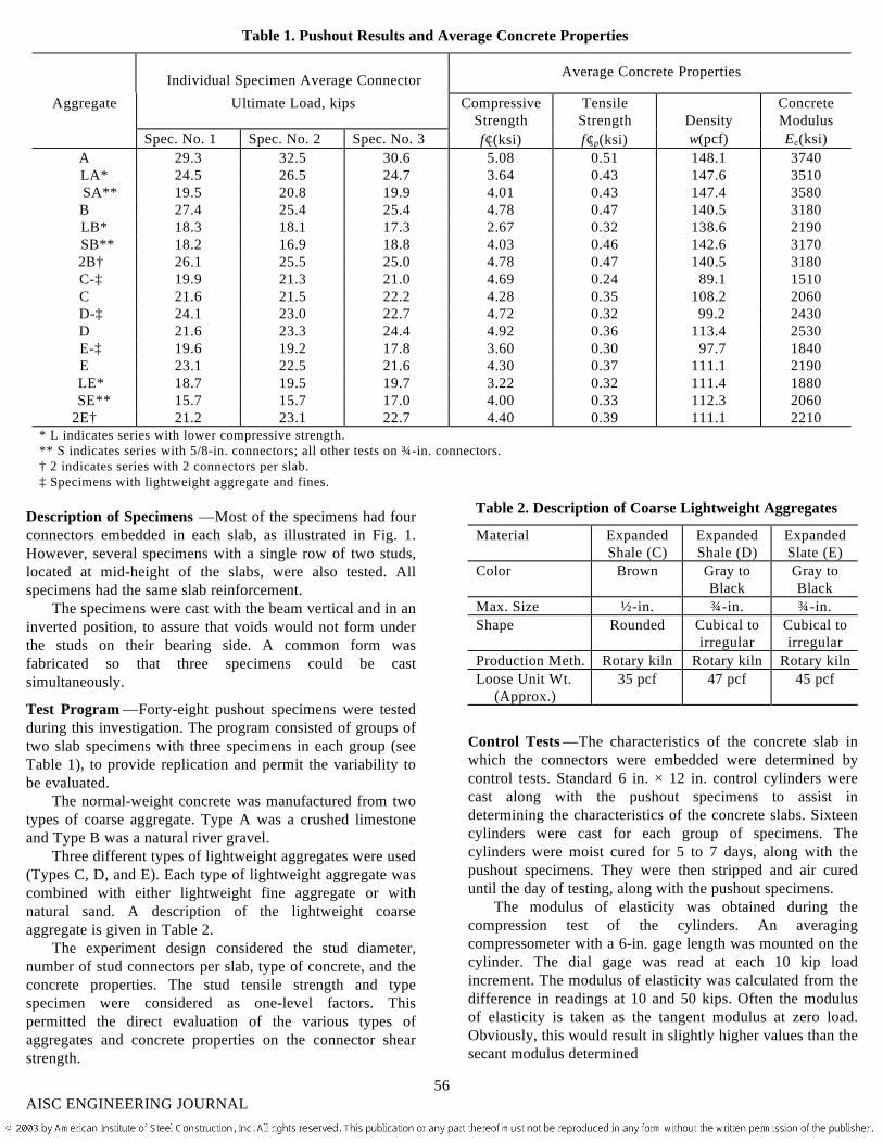
Table 1. Pushout Results and Average Concrete Properties
Individual Specimen Average Connector Average Concrete Properties
Aggregate Ultimate Load, kips CompressiveStrength
TensileStrength Density
ConcreteModulus
Spec. No. 1 Spec. No. 2 Spec. No. 3 f′c(ksi) f′sp(ksi) w(pcf) Ec(ksi)A 29.3 32.5 30.6 5.08 0.51 148.1 3740LA* 24.5 26.5 24.7 3.64 0.43 147.6 3510SA** 19.5 20.8 19.9 4.01 0.43 147.4 3580B 27.4 25.4 25.4 4.78 0.47 140.5 3180LB* 18.3 18.1 17.3 2.67 0.32 138.6 2190SB** 18.2 16.9 18.8 4.03 0.46 142.6 31702B† 26.1 25.5 25.0 4.78 0.47 140.5 3180C-‡ 19.9 21.3 21.0 4.69 0.24 89.1 1510C 21.6 21.5 22.2 4.28 0.35 108.2 2060D-‡ 24.1 23.0 22.7 4.72 0.32 99.2 2430D 21.6 23.3 24.4 4.92 0.36 113.4 2530E-‡ 19.6 19.2 17.8 3.60 0.30 97.7 1840E 23.1 22.5 21.6 4.30 0.37 111.1 2190LE* 18.7 19.5 19.7 3.22 0.32 111.4 1880SE** 15.7 15.7 17.0 4.00 0.33 112.3 2060
2E† 21.2 23.1 22.7 4.40 0.39 111.1 2210* L indicates series with lower compressive strength.** S indicates series with 5/8-in. connectors; all other tests on ¾-in. connectors.† 2 indicates series with 2 connectors per slab.‡ Specimens with lightweight aggregate and fines.
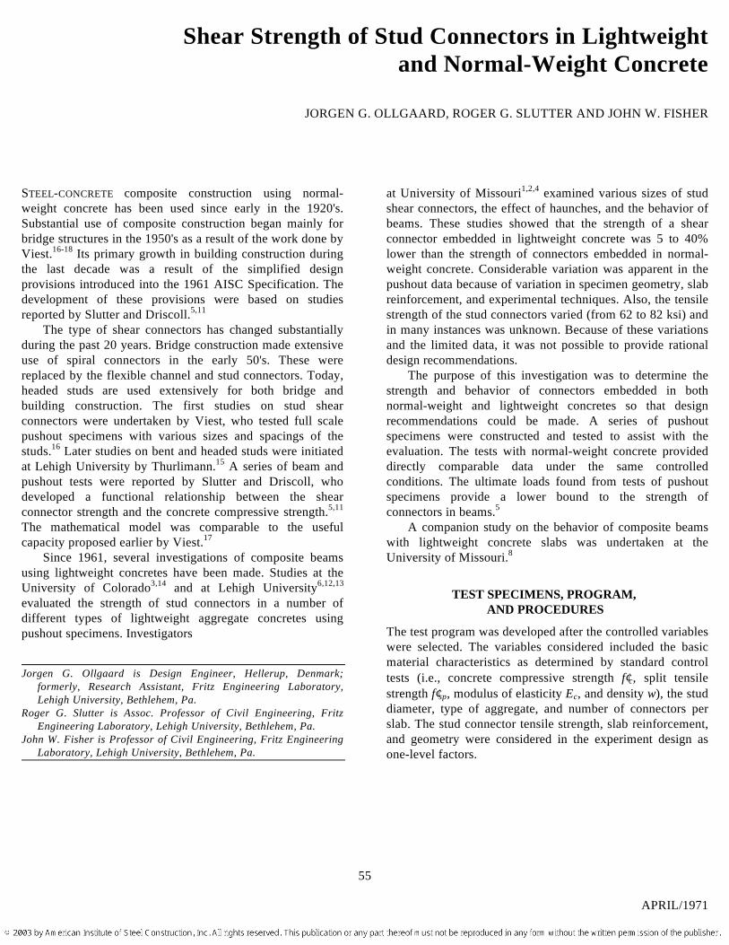
Description of Specimens —Most of the specimens had fourconnectors embedded in each slab, as illustrated in Fig. 1.However, several specimens with a single row of two studs,located at mid-height of the slabs, were also tested. Allspecimens had the same slab reinforcement.
The specimens were cast with the beam vertical and in aninverted position, to assure that voids would not form underthe studs on their bearing side. A common form wasfabricated so that three specimens could be castsimultaneously.
Test Program —Forty-eight pushout specimens were testedduring this investigation. The program consisted of groups oftwo slab specimens with three specimens in each group (seeTable 1), to provide replication and permit the variability tobe evaluated.
The normal-weight concrete was manufactured from twotypes of coarse aggregate. Type A was a crushed limestoneand Type B was a natural river gravel.
Three different types of lightweight aggregates were used(Types C, D, and E). Each type of lightweight aggregate wascombined with either lightweight fine aggregate or withnatural sand. A description of the lightweight coarseaggregate is given in Table 2.
The experiment design considered the stud diameter,number of stud connectors per slab, type of concrete, and theconcrete properties. The stud tensile strength and typespecimen were considered as one-level factors. Thispermitted the direct evaluation of the various types ofaggregates and concrete properties on the connector shearstrength.
Table 2. Description of Coarse Lightweight Aggregates
Material ExpandedShale (C)
ExpandedShale (D)
ExpandedSlate (E)
Color Brown Gray toBlack
Gray toBlack
Max. Size ½-in. ¾-in. ¾-in.Shape Rounded Cubical to
irregularCubical toirregular
Production Meth. Rotary kiln Rotary kiln Rotary kilnLoose Unit Wt.
(Approx.)35 pcf 47 pcf 45 pcf
Control Tests —The characteristics of the concrete slab inwhich the connectors were embedded were determined bycontrol tests. Standard 6 in. × 12 in. control cylinders werecast along with the pushout specimens to assist indetermining the characteristics of the concrete slabs. Sixteencylinders were cast for each group of specimens. Thecylinders were moist cured for 5 to 7 days, along with thepushout specimens. They were then stripped and air cureduntil the day of testing, along with the pushout specimens.
The modulus of elasticity was obtained during thecompression test of the cylinders. An averagingcompressometer with a 6-in. gage length was mounted on thecylinder. The dial gage was read at each 10 kip loadincrement. The modulus of elasticity was calculated from thedifference in readings at 10 and 50 kips. Often the modulusof elasticity is taken as the tangent modulus at zero load.Obviously, this would result in slightly higher values than thesecant modulus determined
56AISC ENGINEERING JOURNAL
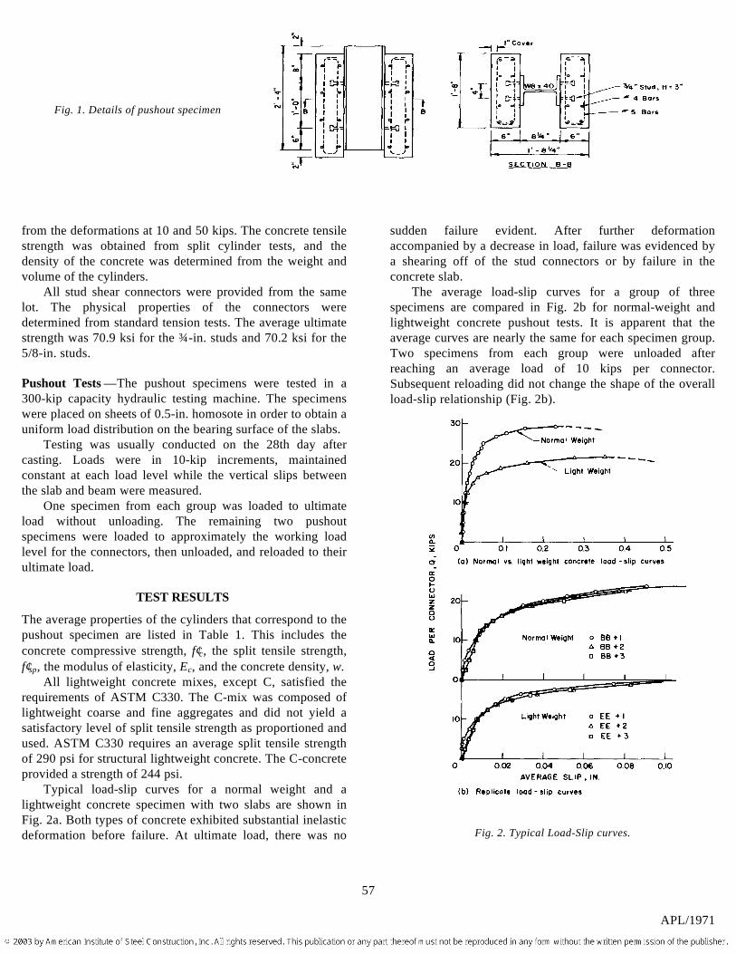
Fig. 1. Details of pushout specimen
from the deformations at 10 and 50 kips. The concrete tensilestrength was obtained from split cylinder tests, and thedensity of the concrete was determined from the weight andvolume of the cylinders.
All stud shear connectors were provided from the samelot. The physical properties of the connectors weredetermined from standard tension tests. The average ultimatestrength was 70.9 ksi for the ¾-in. studs and 70.2 ksi for the5/8-in. studs.
Pushout Tests —The pushout specimens were tested in a300-kip capacity hydraulic testing machine. The specimenswere placed on sheets of 0.5-in. homosote in order to obtain auniform load distribution on the bearing surface of the slabs.
Testing was usually conducted on the 28th day aftercasting. Loads were in 10-kip increments, maintainedconstant at each load level while the vertical slips betweenthe slab and beam were measured.
One specimen from each group was loaded to ultimateload without unloading. The remaining two pushoutspecimens were loaded to approximately the working loadlevel for the connectors, then unloaded, and reloaded to theirultimate load.
TEST RESULTS
The average properties of the cylinders that correspond to thepushout specimen are listed in Table 1. This includes theconcrete compressive strength, f′c, the split tensile strength,f′sp, the modulus of elasticity, Ec, and the concrete density, w.
All lightweight concrete mixes, except C, satisfied therequirements of ASTM C330. The C-mix was composed oflightweight coarse and fine aggregates and did not yield asatisfactory level of split tensile strength as proportioned andused. ASTM C330 requires an average split tensile strengthof 290 psi for structural lightweight concrete. The C-concreteprovided a strength of 244 psi.
Typical load-slip curves for a normal weight and alightweight concrete specimen with two slabs are shown inFig. 2a. Both types of concrete exhibited substantial inelasticdeformation before failure. At ultimate load, there was no
sudden failure evident. After further deformationaccompanied by a decrease in load, failure was evidenced bya shearing off of the stud connectors or by failure in theconcrete slab.
The average load-slip curves for a group of threespecimens are compared in Fig. 2b for normal-weight andlightweight concrete pushout tests. It is apparent that theaverage curves are nearly the same for each specimen group.Two specimens from each group were unloaded afterreaching an average load of 10 kips per connector.Subsequent reloading did not change the shape of the overallload-slip relationship (Fig. 2b).
Fig. 2. Typical Load-Slip curves.
57
APL/1971
The ultimate load per shear connector for each pushoutspecimen is listed in Table 1. The ultimate loads did not varymuch between the replicate specimens of a test group. Veryseldom did the standard deviation exceed 1 kip. It is apparentthat the connector strengths were decreased significantly(from 15 to 25%) when the connectors were embedded inlightweight concrete. The sanded lightweight concretesprovided slightly higher shear strengths than did the alllightweight concrete mixes.
In this study the tensile strengths of all the 5/8-in. and ¾-in. connectors were the same (approximately 70.7 ksi).Hence, the results of the tests on different diameterconnectors provided direct information on the influence ofconnector diameter. Stud connectors of both sizes wereembedded in the two normal-weight concretes and onelightweight concrete. The results show that the connectorshear strength is nearly proportional to the cross-sectionalarea of the stud.
Failure Modes —Most specimens were subjected toadditional loading and deformation after the ultimate loadwas reached. Often, slab cracks were visible just afterultimate load was reached. The loading was normallycontinued until one or both slabs separated from the steelbeam. This occurred at large slips. There were basically twoseparation modes observed. In one, the studs were shearedoff the steel beam and remained embedded in the slab afterunloading occurred. In the other, the concrete failed in theregion of the shear connectors. In many tests both types offailures were observed in the same specimen.
Specimen A2, which had normal-weight concrete slabs,
(a) Studs sheared off.
exhibited the typical stud shear failure. Figure 3a shows thefour studs that were embedded in one slab which sheared off.The other slab was still connected to the steel beam. Thephotograph also indicates that the studs did not shear off atthe same slip levels since the gaps between the studs and theslab are not the same size indicating that different amounts ofplastic deformation occurred.
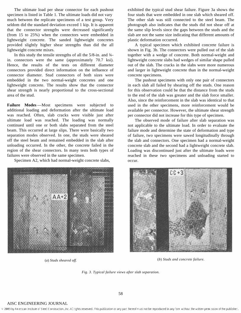
A typical specimen which exhibited concrete failure isshown in Fig. 3b. The connectors were pulled out of the slabtogether with a wedge of concrete. Both normal-weight andlightweight concrete slabs had wedges of similar shape pulledout of the slab. The cracks in the slabs were more numerousand larger in lightweight concrete than in the normal-weightconcrete specimens.
The pushout specimens with only one pair of connectorsin each slab all failed by shearing off the studs. One reasonfor this observation could be that the distance from the studsto the end of the slab was greater and the slab force smaller.Also, since the reinforcement in the slab was identical to thatused in the other specimens, more reinforcement would beavailable per connector. However, the ultimate shear strengthper connector did not increase for this type of specimen.
The observed mode of failure after slab separation wasnot applicable to the ultimate load. In order to evaluate thefailure mode and determine the state of deformation and typeof failure, two specimens were sawed longitudinally throughthe slab and connectors. One specimen had a normal-weightconcrete slab and the second had a lightweight concrete slab.Loading was discontinued just after the ultimate loads werereached in these two specimens and unloading started tooccur.
(b) Studs and concrete failure.
Fig. 3. Typical failure views after slab separation.
58
AISC ENGINEERING JOURNAL
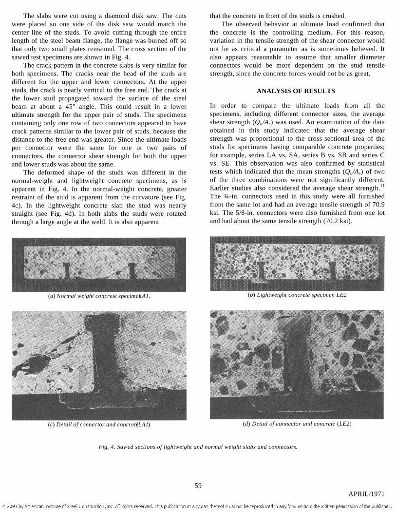
The slabs were cut using a diamond disk saw. The cutswere placed so one side of the disk saw would match thecenter line of the studs. To avoid cutting through the entirelength of the steel beam flange, the flange was burned off sothat only two small plates remained. The cross section of thesawed test specimens are shown in Fig. 4.
The crack pattern in the concrete slabs is very similar forboth specimens. The cracks near the head of the studs aredifferent for the upper and lower connectors. At the upperstuds, the crack is nearly vertical to the free end. The crack atthe lower stud propagated toward the surface of the steelbeam at about a 45° angle. This could result in a lowerultimate strength for the upper pair of studs. The specimenscontaining only one row of two connectors appeared to havecrack patterns similar to the lower pair of studs, because thedistance to the free end was greater. Since the ultimate loadsper connector were the same for one or two pairs ofconnectors, the connector shear strength for both the upperand lower studs was about the same.
The deformed shape of the studs was different in thenormal-weight and lightweight concrete specimens, as isapparent in Fig. 4. In the normal-weight concrete, greaterrestraint of the stud is apparent from the curvature (see Fig.4c). In the lightweight concrete slab the stud was nearlystraight (see Fig. 4d). In both slabs the studs were rotatedthrough a large angle at the weld. It is also apparent
(a) Normal weight concrete specimen LA1.
(c) Detail of connector and concrete (LA1)
that the concrete in front of the studs is crushed.The observed behavior at ultimate load confirmed that
the concrete is the controlling medium. For this reason,variation in the tensile strength of the shear connector wouldnot be as critical a parameter as is sometimes believed. Italso appears reasonable to assume that smaller diameterconnectors would be more dependent on the stud tensilestrength, since the concrete forces would not be as great.
ANALYSIS OF RESULTS
In order to compare the ultimate loads from all thespecimens, including different connector sizes, the averageshear strength (Qu/As) was used. An examination of the dataobtained in this study indicated that the average shearstrength was proportional to the cross-sectional area of thestuds for specimens having comparable concrete properties;for example, series LA vs. SA, series B vs. SB and series Cvs. SE. This observation was also confirmed by statisticaltests which indicated that the mean strengths (Qu/As) of twoof the three combinations were not significantly different.Earlier studies also considered the average shear strength.11
The ¾-in. connectors used in this study were all furnishedfrom the same lot and had an average tensile strength of 70.9ksi. The 5/8-in. connectors were also furnished from one lotand had about the same tensile strength (70.2 ksi).
(b) Lightweight concrete specimen LE2
(d) Detail of connector and concrete (LE2)
Fig. 4. Sawed sections of lightweight and normal weight slabs and connectors.
59APRIL/1971
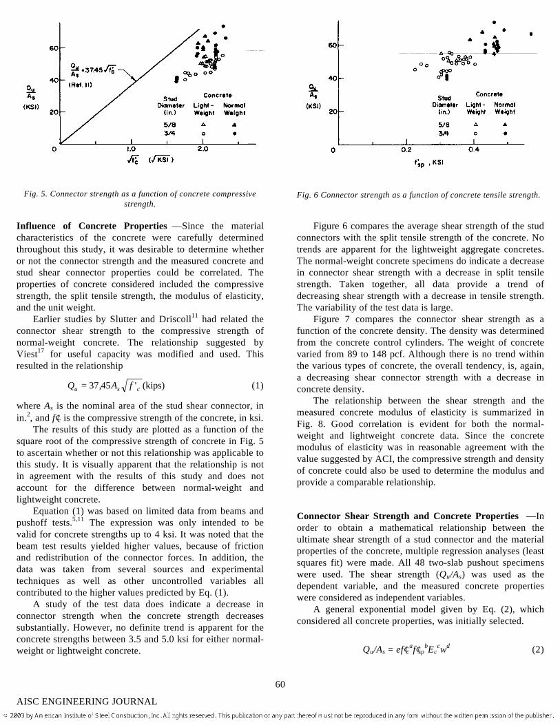
Fig. 5. Connector strength as a function of concrete compressivestrength.
Influence of Concrete Properties —Since the materialcharacteristics of the concrete were carefully determinedthroughout this study, it was desirable to determine whetheror not the connector strength and the measured concrete andstud shear connector properties could be correlated. Theproperties of concrete considered included the compressivestrength, the split tensile strength, the modulus of elasticity,and the unit weight.
Earlier studies by Slutter and Driscoll11 had related theconnector shear strength to the compressive strength ofnormal-weight concrete. The relationship suggested byViest17 for useful capacity was modified and used. Thisresulted in the relationship
Q A fu s c= 37 45, ' (kips) (1)
where As is the nominal area of the stud shear connector, inin.2, and f′c is the compressive strength of the concrete, in ksi.
The results of this study are plotted as a function of thesquare root of the compressive strength of concrete in Fig. 5to ascertain whether or not this relationship was applicable tothis study. It is visually apparent that the relationship is notin agreement with the results of this study and does notaccount for the difference between normal-weight andlightweight concrete.
Equation (1) was based on limited data from beams andpushoff tests.5,11 The expression was only intended to bevalid for concrete strengths up to 4 ksi. It was noted that thebeam test results yielded higher values, because of frictionand redistribution of the connector forces. In addition, thedata was taken from several sources and experimentaltechniques as well as other uncontrolled variables allcontributed to the higher values predicted by Eq. (1).
A study of the test data does indicate a decrease inconnector strength when the concrete strength decreasessubstantially. However, no definite trend is apparent for theconcrete strengths between 3.5 and 5.0 ksi for either normal-weight or lightweight concrete.
Fig. 6 Connector strength as a function of concrete tensile strength.
Figure 6 compares the average shear strength of the studconnectors with the split tensile strength of the concrete. Notrends are apparent for the lightweight aggregate concretes.The normal-weight concrete specimens do indicate a decreasein connector shear strength with a decrease in split tensilestrength. Taken together, all data provide a trend ofdecreasing shear strength with a decrease in tensile strength.The variability of the test data is large.
Figure 7 compares the connector shear strength as afunction of the concrete density. The density was determinedfrom the concrete control cylinders. The weight of concretevaried from 89 to 148 pcf. Although there is no trend withinthe various types of concrete, the overall tendency, is, again,a decreasing shear connector strength with a decrease inconcrete density.
The relationship between the shear strength and themeasured concrete modulus of elasticity is summarized inFig. 8. Good correlation is evident for both the normal-weight and lightweight concrete data. Since the concretemodulus of elasticity was in reasonable agreement with thevalue suggested by ACI, the compressive strength and densityof concrete could also be used to determine the modulus andprovide a comparable relationship.
Connector Shear Strength and Concrete Properties —Inorder to obtain a mathematical relationship between theultimate shear strength of a stud connector and the materialproperties of the concrete, multiple regression analyses (leastsquares fit) were made. All 48 two-slab pushout specimenswere used. The shear strength (Qu/As) was used as thedependent variable, and the measured concrete propertieswere considered as independent variables.
A general exponential model given by Eq. (2), whichconsidered all concrete properties, was initially selected.
Qu/As = ef′caf′spbEc
cwd (2)
60
AISC ENGINEERING JOURNAL
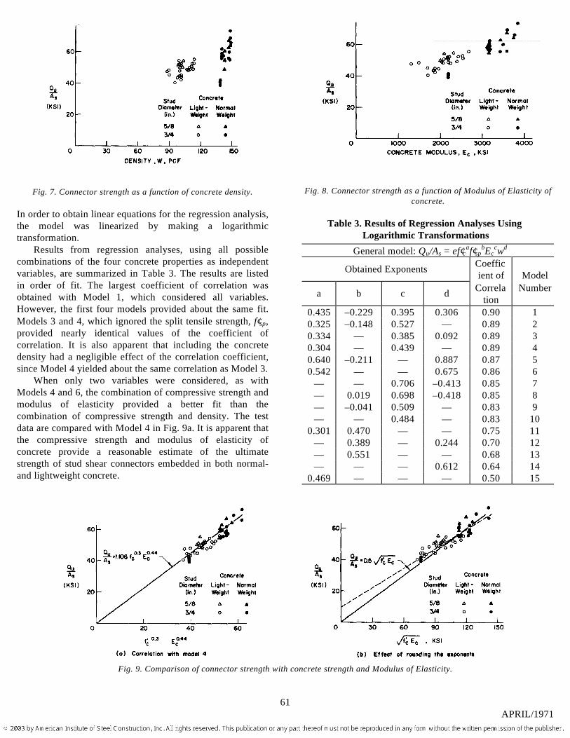
Fig. 7. Connector strength as a function of concrete density.
In order to obtain linear equations for the regression analysis,the model was linearized by making a logarithmictransformation.
Results from regression analyses, using all possiblecombinations of the four concrete properties as independentvariables, are summarized in Table 3. The results are listedin order of fit. The largest coefficient of correlation wasobtained with Model 1, which considered all variables.However, the first four models provided about the same fit.Models 3 and 4, which ignored the split tensile strength, f′sp,provided nearly identical values of the coefficient ofcorrelation. It is also apparent that including the concretedensity had a negligible effect of the correlation coefficient,since Model 4 yielded about the same correlation as Model 3.
When only two variables were considered, as withModels 4 and 6, the combination of compressive strength andmodulus of elasticity provided a better fit than thecombination of compressive strength and density. The testdata are compared with Model 4 in Fig. 9a. It is apparent thatthe compressive strength and modulus of elasticity ofconcrete provide a reasonable estimate of the ultimatestrength of stud shear connectors embedded in both normal-and lightweight concrete.
Fig. 8. Connector strength as a function of Modulus of Elasticity ofconcrete.
Table 3. Results of Regression Analyses UsingLogarithmic Transformations
General model: Qu/As = ef′caf′spbEc
cwd
Obtained Exponents Coefficient of Model
a b c d Correlation
Number
0.435 –0.229 0.395 0.306 0.90 10.325 –0.148 0.527 — 0.89 20.334 — 0.385 0.092 0.89 30.304 — 0.439 — 0.89 40.640 –0.211 — 0.887 0.87 50.542 — — 0.675 0.86 6
— — 0.706 –0.413 0.85 7— 0.019 0.698 –0.418 0.85 8— –0.041 0.509 — 0.83 9— — 0.484 — 0.83 10
0.301 0.470 — — 0.75 11— 0.389 — 0.244 0.70 12— 0.551 — — 0.68 13— — — 0.612 0.64 14
0.469 — — — 0.50 15
Fig. 9. Comparison of connector strength with concrete strength and Modulus of Elasticity.
61APRIL/1971
Effect of Rounding Off Exponents —Since it is desirable touse more convenient exponents, analyses were made todetermine the effect of rounding the exponents obtained forModels 4 and 6. Several sets of exponents were examined foreach model. Rounding the exponents decreased thecoefficient of correlation by less than 1.7%. Hence, theexponents can be rounded off without significantly affectingthe overall fit to the test data.
The test data are compared with the modified Model 4 inFig. 9b. The dashed line is the least squares fit to the testdata when both exponents were rounded to 0.5. The solid linewas determined by forcing the model to conform to theorigin. It is apparent that the fit to the data is not appreciablyaffected when the intercept is ignored.
As noted earlier, the modulus of elasticity for theconcrete can be determined from the concrete compressivestrength and density by use of the ACI formula. Hence Model6, which includes concrete compressive strength and density,can be transformed into Model 4, which considerscompressive strength and the modulus of elasticity ofconcrete. For design purposes, Eq. (3) provides a reasonableestimate for both Models 4 and 6
Q A f Eu s c c= 05. ' (3)
This relationship provides a good estimate of the ultimatestrength of shear connectors embedded in both normal-weightand lightweight concrete slabs. Equation (3) expresses theshear connector strength as a function of the stud connectorarea and concrete properties. The influence of the type ofaggregate is reflected in the modulus of elasticity.
Comparison with Earlier Studies —Test data are availablefrom a number of investigations that were made prior to thisstudy. Driscoll and Slutter5 observed that the height-to-diameter ratio (H/d) for studs embedded in normal-weightconcrete should be equal to or larger than 4 if the fullcapacity of the connector is to be developed. Specimenswhich did not satisfy this requirement were not considered.
Only specimens which had one or two connectors per rowwere considered, since increasing the number of connectorshas been shown to influence the shear strength per stud whenthe slab width and reinforcement are not changed.16
A number of haunched specimens were tested at theUniversity of Missouri.2 Shear strength per connector for thistype of specimen was lower than other solid slab specimens.They are not included in the comparison.
Investigators at the University of Sydney10 examinedsmall scale lightweight concrete specimens with 3/8-in. studs.Most of the concrete slabs were not reinforced. The shearstrength (Qu/As) for the specimens without reinforcementwere in the range of data from other investigations
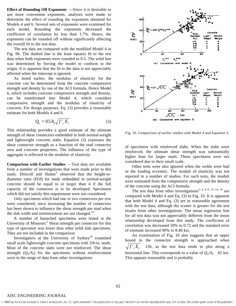
Fig. 10. Comparison of earlier studies with Model 4 and Equation 3.
of specimens with reinforced slabs. When the slabs werereinforced, the ultimate shear strength was substantiallyhigher than for larger studs. These specimens were notconsidered due to their small scale.
Other tests were also ignored when the welds were bador the loading eccentric. The moduli of elasticity was notreported in a number of studies. For such tests, the moduliwere estimated from the compressive strength and the densityof the concrete using the ACI formula.
The test data from other investigations2, 4, 6–9, 12–14, 16 arecompared with Model 4 and Eq. (3) in Fig. 10. It is apparentthat both Model 4 and Eq. (3) are in reasonable agreementwith the test data, although the scatter is greater for the testresults from other investigations. The mean regression linefor all test data was not appreciably different from the meanrelationship developed from this study. The coefficient ofcorrelation was decreased 18% to 0.72 and the standard errorof estimate increased 90% to 8.46 ksi.
An examination of Fig. 10 also suggests that an upperbound to the connector strength is approached when
f Ec c' ≅ 130, as the test data tends to plot along ahorizontal line. This corresponds to a value of Qu/As ≅ 65 ksi.This appears reasonable and is probably
62
AISC ENGINEERING JOURNAL
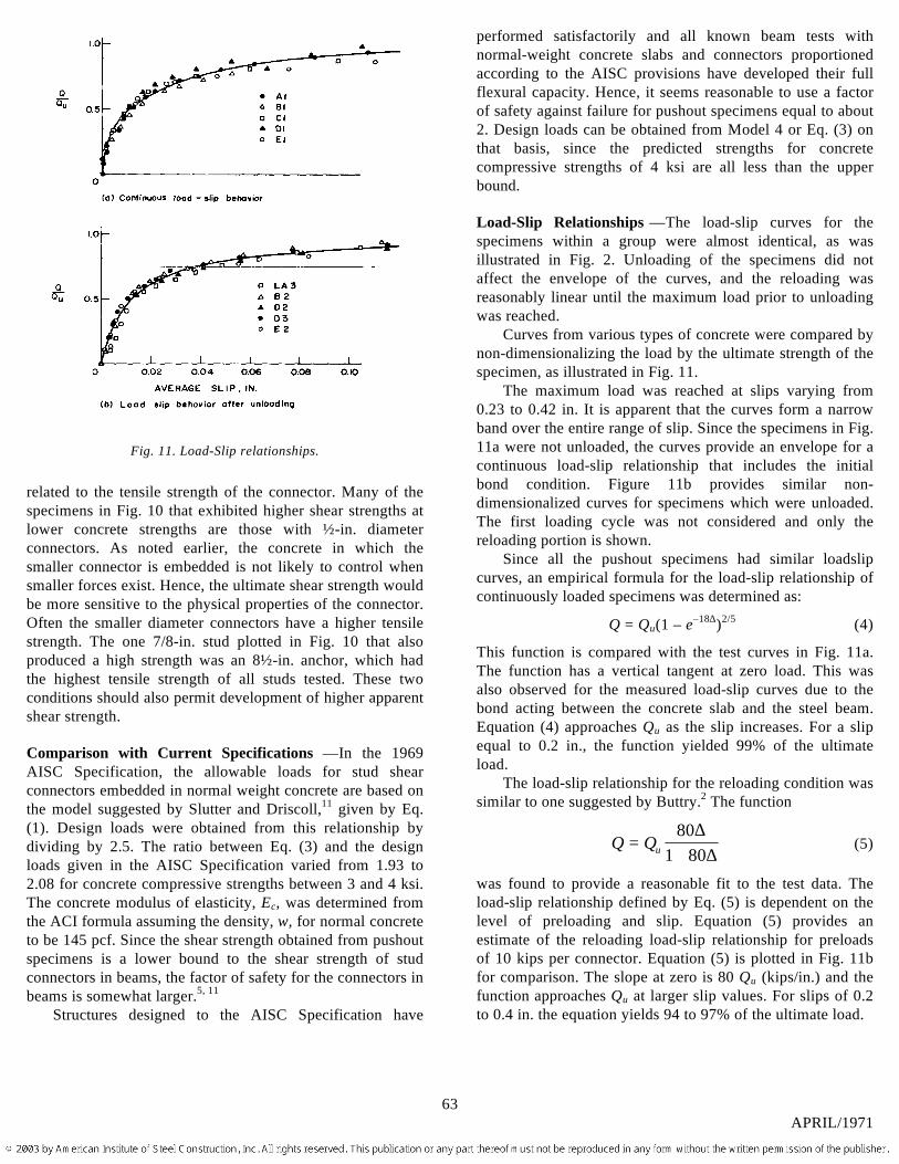
Fig. 11. Load-Slip relationships.
related to the tensile strength of the connector. Many of thespecimens in Fig. 10 that exhibited higher shear strengths atlower concrete strengths are those with ½-in. diameterconnectors. As noted earlier, the concrete in which thesmaller connector is embedded is not likely to control whensmaller forces exist. Hence, the ultimate shear strength wouldbe more sensitive to the physical properties of the connector.Often the smaller diameter connectors have a higher tensilestrength. The one 7/8-in. stud plotted in Fig. 10 that alsoproduced a high strength was an 8½-in. anchor, which hadthe highest tensile strength of all studs tested. These twoconditions should also permit development of higher apparentshear strength.
Comparison with Current Specifications —In the 1969AISC Specification, the allowable loads for stud shearconnectors embedded in normal weight concrete are based onthe model suggested by Slutter and Driscoll,11 given by Eq.(1). Design loads were obtained from this relationship bydividing by 2.5. The ratio between Eq. (3) and the designloads given in the AISC Specification varied from 1.93 to2.08 for concrete compressive strengths between 3 and 4 ksi.The concrete modulus of elasticity, Ec, was determined fromthe ACI formula assuming the density, w, for normal concreteto be 145 pcf. Since the shear strength obtained from pushoutspecimens is a lower bound to the shear strength of studconnectors in beams, the factor of safety for the connectors inbeams is somewhat larger.5, 11
Structures designed to the AISC Specification have
performed satisfactorily and all known beam tests withnormal-weight concrete slabs and connectors proportionedaccording to the AISC provisions have developed their fullflexural capacity. Hence, it seems reasonable to use a factorof safety against failure for pushout specimens equal to about2. Design loads can be obtained from Model 4 or Eq. (3) onthat basis, since the predicted strengths for concretecompressive strengths of 4 ksi are all less than the upperbound.
Load-Slip Relationships —The load-slip curves for thespecimens within a group were almost identical, as wasillustrated in Fig. 2. Unloading of the specimens did notaffect the envelope of the curves, and the reloading wasreasonably linear until the maximum load prior to unloadingwas reached.
Curves from various types of concrete were compared bynon-dimensionalizing the load by the ultimate strength of thespecimen, as illustrated in Fig. 11.
The maximum load was reached at slips varying from0.23 to 0.42 in. It is apparent that the curves form a narrowband over the entire range of slip. Since the specimens in Fig.11a were not unloaded, the curves provide an envelope for acontinuous load-slip relationship that includes the initialbond condition. Figure 11b provides similar non-dimensionalized curves for specimens which were unloaded.The first loading cycle was not considered and only thereloading portion is shown.
Since all the pushout specimens had similar loadslipcurves, an empirical formula for the load-slip relationship ofcontinuously loaded specimens was determined as:
Q = Qu(1 – e–18∆)2/5 (4)
This function is compared with the test curves in Fig. 11a.The function has a vertical tangent at zero load. This wasalso observed for the measured load-slip curves due to thebond acting between the concrete slab and the steel beam.Equation (4) approaches Qu as the slip increases. For a slipequal to 0.2 in., the function yielded 99% of the ultimateload.
The load-slip relationship for the reloading condition wassimilar to one suggested by Buttry.2 The function
Q Qu=+80
1 80∆
∆(5)
was found to provide a reasonable fit to the test data. Theload-slip relationship defined by Eq. (5) is dependent on thelevel of preloading and slip. Equation (5) provides anestimate of the reloading load-slip relationship for preloadsof 10 kips per connector. Equation (5) is plotted in Fig. 11bfor comparison. The slope at zero is 80 Qu (kips/in.) and thefunction approaches Qu at larger slip values. For slips of 0.2to 0.4 in. the equation yields 94 to 97% of the ultimate load.
63APRIL/1971
SUMMARY AND CONCLUSIONS
This study summarizes the results of tests on 48 two-slabpushout specimens. The main purpose of the investigationwas to evaluate the capacity and behavior of stud shearconnectors embedded in lightweight concrete. Two differenttypes of normal-weight aggregates and three types oflightweight aggregate were examined. The lightweightconcretes were made with both lightweight coarse aggregatewith natural sand and with lightweight fines.
The following conclusions were drawn from this study:1. The shear strength of stud connectors embedded in
normal-weight and lightweight concrete was primarilyinfluenced by the compressive strength and the modulus ofelasticity of the concrete. The following empirical functiondescribed the test results:
Qu = 1.106Asf′c0.3Ec0.44
while the following simplified equation is satisfactory fordesign purposes:
Q A f Eu s c c= 12 '
where f′c is the concrete compressive strength (ksi), Ec themodulus of elasticity (ksi), and As the cross-sectional area ofthe stud shear connector (in.2).
2. Other concrete properties including the concretetensile strength and density did not significantly improve thefit to the test data.
3. Pushout specimens with either one or two rows ofstuds per slab exhibited the same average strength per stud.
4. The shear strength was approximately proportional tothe cross-sectional area of the studs.
5. The load-slip relationship for continuous loading canbe expressed as:
Q = Qu(1 – e–18∆)2/5
where Q is the load and ∆ is the slip in inches.
ACKNOWLEDGMENTS
The investigation reported herein was conducted at FritzEngineering Laboratory, Lehigh University. This work is partof a cooperative study with the University of Missouri atColumbia. The Committees of Structural Shape and SteelPlate Producers of the American Iron and Steel Institute andthe Expanded Shale, Clay and Slate Institute jointlysponsored the research.
The program was performed under the guidance of anAdvisory Committee under the chairmanship of I. M. Viest.Messrs. J. W. Baldwin, Jr., J. Chinn, F. G. Erskine, J. W.Fisher, T. A. Holm, I. M. Hooper, H. S. Lew, J. B.McGarraugh, R. C. Singleton, and R. G. Slutter served on theCommittee. The authors wish to acknowledge their guidanceand advice.
REFERENCES
1. Baldwin, J. W., Henry, J. R. and Sweeney, C. M. Study ofComposite Bridge Stringers Phase II, University of Missouri,May, 1965.
2. Buttry, K. E. Behavior of Stud Shear Connectors in Lightweightand Normal-Weight Concrete M.S. Thesis, University ofMissouri, August, 1965, Unpublished.
3. Chinn, J. The Use of Nelson Studs with Idealite Lightweight-Aggregate Concrete in Composite Construction Part 1,Engineering Experiment Station, University of Colorado,Boulder, Colorado, April, 1961 (Summarized in AISCEngineering Journal, Vol. 2, No. 4, October, 1965).
4. Dallam, L. N. and Pauw, A. Study of Composite BridgeStringers Phase I, University of Missouri, August, 1963,Unpublished.
5. Driscoll, G. G. and Slutter, R. G. Research on CompositeDesign at Lehigh University Proceedings, National EngineeringConference, AISC, May, 1961.
6. Fisher, J. W., Kim, S. W. and Slutter, R. G. Tests of LightweightComposite Beams and Pushout Specimens with Cellular SteelDeck Lehigh University, Fritz Engineering Laboratory ReportNo. 200.67.438.1, July, 1967, Unpublished.
7. Goble, G. G. Influence of Stud Yield Strength of CompositeSpecimens Case Institute of Technology, Cleveland, 1965,Unpublished Report.
8. McGarraugh, J. B. and Baldwin, J. W. Lightweight Concrete-on-Steel Composite Beams (to be published).
9. Poletto, R. J., Corrado, J. A. and Slutter, R. G. Flexure andPushout Tests of Composite Steel-Lightweight ConcreteSpecimens with Metal Decking Lehigh University, FritzEngineering, Laboratory Report No. 200.69.81.1, February,1970, Unpublished.
10. Roderic, J. W., Hawkins, N. M. and Lim, L. C. The Behavior ofComposite Steel and Lightweight Concrete Beams TheInstitution of Engineers, Australia, Symposium on ConcreteStructures, Sydney, 1967.
11. Slutter, R. G. and Driscoll, G. C. Flexural Strength of Steel-Concrete Composite Beams Journal of the Structural Division,ASCE, Vol. 91, No. ST2, April 1965.
12. Slutter, R. G. Pushout Tests of Welded Stud Shear Connectorsin Lightweight Concrete Lehigh University, Fritz EngineeringLaboratory Report No. 200.63.409.1, June, 1963, Unpublished.
13. Slutter, R. G. Pushout Tests of Stud Shear Connectors inLightweight Concrete Lehigh University, Fritz EngineeringLaboratory, Reports No. 200.65.360.1 and 200.66.360.1, 1966,Unpublished.
14. Steele, D. H. and Chinn, J. Tests of Pushout Specimens forComposite Construction with Lightweight Concrete Part I,Department of Civil Engineering, Engineering Research Center,University of Colorado, 1967.
15. Thurlimann, B. Fatigue and Static Strength of Stud ShearConnectors Journal of the American Concrete Institute, Vol. 30,June, 1959.
16. Viest, I. M. Test of Stud Shear Connectors Parts I, II, III andIV, Engrg. Test Data, Nelson Stud Welding, Lorain, Ohio, 1956.
15. Viest, I. M. Investigation of Stud Shear Connectors forComposite Concrete and Steel T-Beams Journal of theAmerican Concrete Institute, Vol. 27, April, 1956.
18. Viest, I. M. Review of Research on Composite Steel-ConcreteBeams Journal of the Structural Division, ASCE, Vol. 86, No.ST6, June 1960.
64
AISC ENGINEERING JOURNAL