Embed Size (px)
Citation preview
3/2
RELI
EF V
ALV
E(O
PTIO
NA
L)
L
R
OFF
ON
ACTU
ATO
R CO
NN
ECTI
ON
d
D
Hh
B
A
b
93
82
14
14
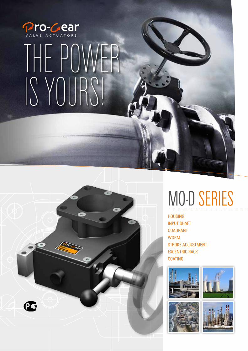
the poweris yours!
11/2
010
MO-D serieshousing
input shaft
quadrant
worm
stroke adjustment
excentric rack
coating
MO-D series
perfOrMance specificatiOns
--> 6 Models--> Up to 5.000 Nm. Torque range--> - 5° to 95° stroke--> IP68 sealing--> -25 °C to +110 °C (-13 °F to +230 °F) temperature range
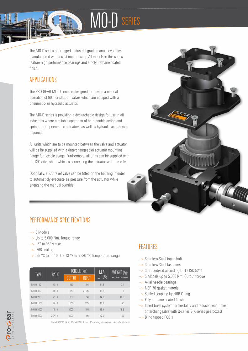
The MO-D series are rugged, industrial grade manual overrides, manufactured with a cast iron housing. All models in this series feature high performance bearings and a polyurethane coated finish.
applicatiOns
The PRO-GEAR MO-D series is designed to provide a manual operation of 90° for shut-off valves which are equiped with a pneumatic- or hydraulic actuator.
The MO-D series is providing a declutchable design for use in all industries where a reliable operation of both double acting and spring return pneumatic actuators, as well as hydraulic actuators is required.
All units which are to be mounted between the valve and actuator will be be supplied with a (interchangeable) actuator mounting flange for flexible usage. Furthermore, all units can be supplied with the ISO drive shaft which is connecting the actuator with the valve.
Optionally, a 3/2 relief valve can be fitted on the housing in order to automaticly evacuate air pressure from the actuator while engaging the manual override.
type ratiOtOrQue (Nm) M.a.
± 10%weiGht (Kg)excl. insert & adaptorOutput input
MO-D 150 40 : 1 150 12.6 11.9 3.1
MO-D 350 44 : 1 350 31.25 11.2 6
MO-D 700 52 : 1 700 50 14.0 16.3
MO-D 1600 42 : 1 1600 125 12.8 25
MO-D 3000 72 : 1 3000 155 19.4 49.5
MO-D 5000 267 : 1 5000 95 52.6 56
1Nm=0,737562 lbf.ft. 1Nm=8,8507 lbf.ins. [Converting International Units to British Units]
features
--> Stainless Steel inputshaft--> Stainless Steel fasteners--> Standardised according DIN / ISO 5211--> 5 Models up to 5.000 Nm. Output torque--> Axial needle bearings--> NBR 70 gasket material--> Sealed coupling by NBR O-ring--> Polyurethane coated finish--> Insert bush system for flexibility and reduced lead times
(interchangeable with Q-series & X-series gearboxes)--> Blind tapped PCD’s
the po
wer i
s you
rs!
3/2 RELIEF VALVE(OPTIONAL)
L
R
OFF
ON
ACTUATOR CONNECTION
dD
Hh
B
A
b
11 5 76 8 9 3 82 1412
13 14
7
3/2 RELIEF VALVE(OPTIONAL)
L
R
OFF
ON
ACTUATOR CONNECTION
d
D
Hh
B
A
b
11 5 76 8 9 3 82 1412
13 14
7
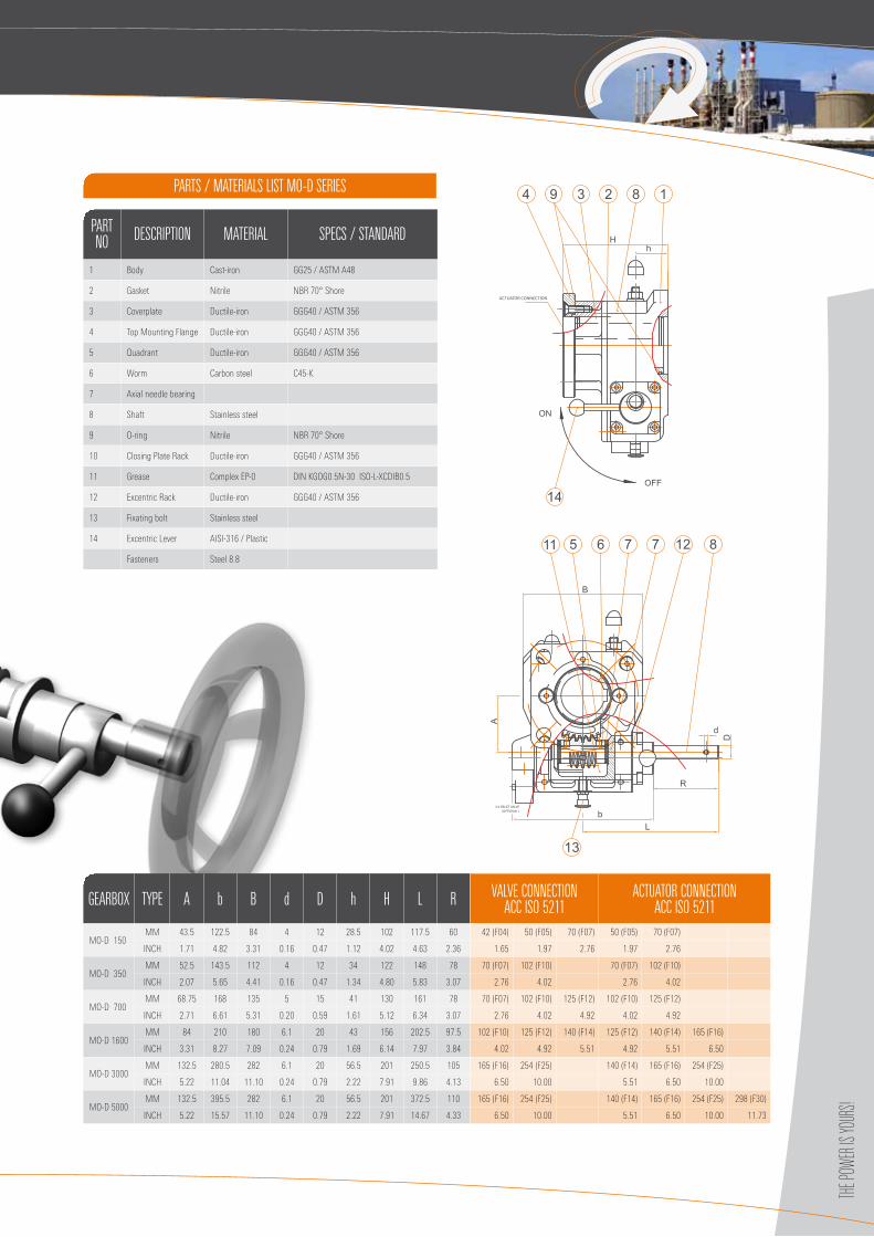
GearbOx type a b b d D h h l r ValVe cOnnectiOn acc isO 5211
actuatOr cOnnectiOn acc isO 5211
MO-D 150MM 43.5 122.5 84 4 12 28.5 102 117.5 60 42 (F04) 50 (F05) 70 (F07) 50 (F05) 70 (F07)
INCH 1.71 4.82 3.31 0.16 0.47 1.12 4.02 4.63 2.36 1.65 1.97 2.76 1.97 2.76
MO-D 350MM 52.5 143.5 112 4 12 34 122 148 78 70 (F07) 102 (F10) 70 (F07) 102 (F10)
INCH 2.07 5.65 4.41 0.16 0.47 1.34 4.80 5.83 3.07 2.76 4.02 2.76 4.02
MO-D 700MM 68.75 168 135 5 15 41 130 161 78 70 (F07) 102 (F10) 125 (F12) 102 (F10) 125 (F12)
INCH 2.71 6.61 5.31 0.20 0.59 1.61 5.12 6.34 3.07 2.76 4.02 4.92 4.02 4.92
MO-D 1600MM 84 210 180 6.1 20 43 156 202.5 97.5 102 (F10) 125 (F12) 140 (F14) 125 (F12) 140 (F14) 165 (F16)
INCH 3.31 8.27 7.09 0.24 0.79 1.69 6.14 7.97 3.84 4.02 4.92 5.51 4.92 5.51 6.50
MO-D 3000MM 132.5 280.5 282 6.1 20 56.5 201 250.5 105 165 (F16) 254 (F25) 140 (F14) 165 (F16) 254 (F25)
INCH 5.22 11.04 11.10 0.24 0.79 2.22 7.91 9.86 4.13 6.50 10.00 5.51 6.50 10.00
MO-D 5000MM 132.5 395.5 282 6.1 20 56.5 201 372.5 110 165 (F16) 254 (F25) 140 (F14) 165 (F16) 254 (F25) 298 (F30)
INCH 5.22 15.57 11.10 0.24 0.79 2.22 7.91 14.67 4.33 6.50 10.00 5.51 6.50 10.00 11.73
parts / Materials list MO-D series
partnO DescriptiOn Material specs / stanDarD
1 Body Cast-iron GG25 / ASTM A48
2 Gasket Nitrile NBR 70° Shore
3 Coverplate Ductile-iron GGG40 / ASTM 356
4 Top Mounting Flange Ductile-iron GGG40 / ASTM 356
5 Quadrant Ductile-iron GGG40 / ASTM 356
6 Worm Carbon steel C45-K
7 Axial needle bearing
8 Shaft Stainless steel
9 O-ring Nitrile NBR 70° Shore
10 Closing Plate Rack Ductile-iron GGG40 / ASTM 356
11 Grease Complex EP-0 DIN KGOG0.5N-30 ISO-L-XCDIB0.5
12 Excentric Rack Ductile-iron GGG40 / ASTM 356
13 Fixating bolt Stainless steel
14 Excentric Lever AISI-316 / Plastic
Fasteners Steel 8.8
MO-D series
11/2
010
Kopenhagener Straße 21D-48455 Bad Bentheim - GildehausTel +49 (0)5924 255 840 - Fax +49 (0)5924 255 841E-mail [email protected] - www.pro-gear.de
the pOwer is yOurs!
Pro-Gear GmbH is a young, highly flexible team, who are carrying out every element of design, assembly and quality control with the utmost care.
The unique combination of the products, together with the know how and assembling facilities are creating for clients a relationship, unique in the valve actuator industries. GOST certificated
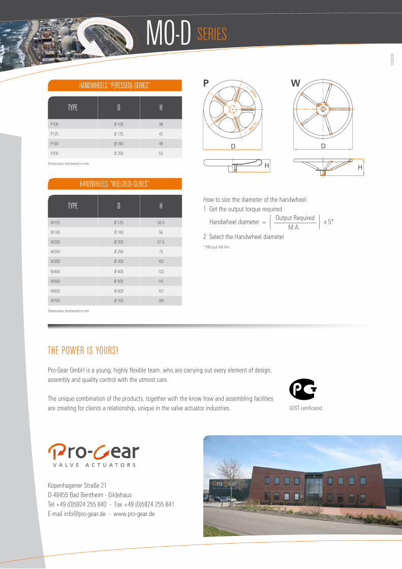
hanDwheels “p(resseD)-series”
hanDwheels “w(elDeD)-series”
type D h
P100 Ø 100 38
P125 Ø 125 42
P160 Ø 160 48
P200 Ø 200 53
Dimensions mentioned in mm.
type D h
W125 Ø 125 50.5
W160 Ø 160 56
W200 Ø 200 67.5
W250 Ø 250 73
W300 Ø 300 102
W400 Ø 400 122
W500 Ø 500 141
W600 Ø 600 157
W700 Ø 700 180
Dimensions mentioned in mm.
H
D
OPEN
CLOSE
H
D
How to size the diameter of the handwheel: 1 Get the output torque required
Handwheel diameter = Output Required
x 5* ( M.A. )2 Select the Handwheel diameter* RIM pull 400 Nm
P W