Embed Size (px)
Citation preview
i
On Combustion in the CNG-Diesel Dual Fuel Engine
FREDRIK KÖNIGSSON
Doctoral thesis Department of Machine Design Royal Institute of Technology SE-100 44 Stockholm
TRITA MMK 2014:08 ISSN 1400-1179
ISRN/KTH/MMK/R-14/08-SE ISBN 978-91-7595-243-7

ii
TRITA MMK 2014:08
ISSN 1400-1179
ISRN/KTH/MMK/R-14/08-SE
ISBN 978-91-7595-243-7
On Combustion in the CNG-Diesel Dual Fuel Engine
Fredrik Königsson
Doctoral thesis
Academic thesis which, with the approval of Kungliga Tekniska Högskolan, will be presented for public review in fulfillment of
the requirements for a Doctorate of Engineering in Machine Design. The public review is held at Kungliga Tekniska
Högskolan, Brinellvägen 8, Kollegiesalen, 26th of September at 14:00.

iii
“Messen ist Wissen”
- Werner von Siemens, 1816-1892

iv
v
Abstract Currently there is a large interest in alternative transport fuels. There are two underlying reasons for
this interest: the desire to decrease the environmental impact of transports and the need to
compensate for the declining availability of petroleum. In the light of both these factors, the CNG-
diesel dual fuel engine is an attractive concept. The primary fuel of the dual fuel engine is methane,
which can be derived both from renewables and from fossil sources. Methane from organic waste,
commonly referred to as biomethane, can provide a reduction in greenhouse gases unmatched by
any other fuel. Furthermore, fossil methane, natural gas, is one of the most abundant fossil fuels.
The dual fuel engine is, from a combustion point of view, a hybrid of the diesel and the Otto-engine
and it shares characteristics with both.
From a market standpoint, the dual fuel technology is highly desirable; however, from a technical
point of view it has proven difficult to realize. The aim of this project was to identify limitations to
engine operation, investigate these challenges, and, as much as possible, suggest remedies.
Investigations have been made into emissions formation, nozzle-hole coking, impact of varying in-
cylinder air motion, behavior and root causes of pre-ignitions, and the potential of advanced
injection strategies and unconventional combustion modes. The findings from each of these
investigations have been summarized, and recommendations for the development of a Euro 6
compliant dual fuel engine have been formulated. Two key challenges must be researched further
for this development to succeed: an aftertreatment system which allows for low exhaust
temperatures must be available, and the root cause of pre-ignitions must be found and eliminated.

vi
vii
Sammanfattning För nuvarande finns ett stort intresse för alternativa bränslen. Detta intresse drivs primärt av två
krafter: önskemålet att minska miljöpåverkan från transporter samt behovet att kompensera för den
minskande tillgängligheten på petroleum. I ljuset av båda dessa faktorer framstår CNG-diesel-dual-
fuel-motorn, metan-diesel-motorn, som ett attraktivt koncept. Det huvudsakliga bränslet i dual-fuel-
motorn är metan, ett bränsle som kan framställas både från förnybara och från fossila källor. Metan
från organiskt avfall, biogas, erbjuder en reduktion av växthusgaser som inget annat bränsle kan
matcha och fossil metan, naturgas, är ett av de mest rikligt förekommande fossila bränslena. Dual-
fuel-motorn är ur förbränningssynpunkt en hybrid mellan Otto- och dieselmotorn och den delar
egenskaper med båda dessa.
Ur ett marknadsperspektiv är dual-fuel-motorn mycket attraktiv, dock så har den, ur ett tekniskt
perspektiv, visat sig svår att realisera. Målet med detta projekt var att identifiera gränser för motorns
driftområde, undersöka dessa gränser och, i möjligaste mån, föreslå metoder för att avhjälpa dessa.
Underökningar har utförts inom emissionsbildning, insprutarbeläggningar, varierande luftrörelser i
cylindern, beteende och bakomliggande orsak till pre-ignition samt inom potentialen hos
avancerade insprutningsstrategier och okonventionella förbränningstyper. Lärdomarna från dessa
undersökningar har sammanställts och rekommendationer gällande utveckling av en dual-fuel-
motor som uppfyller emissionsnormen Euro 6 har formulerats. Två avgörande utmaningar återstår
för att en sådan utveckling skall nå framgång: ett efterbehandlingssystem som fungerar trots låga
avgastemperaturer måste finnas tillgängligt och den bakomliggande orsaken till pre-ignition måste
utrönas samt åtgärdas.

viii
ix
Preface The material presented in this thesis was generated as part of an AVL-project to develop
understanding of CNG-diesel dual fuel combustion. Partner in the project was Scania CV. The work
was performed at the group of Internal Combustion Engines at the Royal Institute of Technology,
Stockholm, Sweden. Partial funding was provided by the Swedish Energy Agency. The thesis
consists of an overview of dual fuel combustion and the challenges and opportunities associated
with it. The overview is mainly based on experimental results from the project but also on available
literature.
The following people have contributed to the project and are gratefully acknowledged: Hans-Erik
Ångström, Per Risberg, Andreas Cronhjort, Jonas Holmborn, Ernst Winklhofer, Per Stålhammar,
Stefan Olsson, Henrik Dembinski, Johannes Andersen, Daniel Danielsson, Jack Ivarsson, Bengt
Aronsson and last but not least PhD students, project workers and administrative staff at the Internal
Combustion Engine department.
Stockholm, August 2014
Fredrik Königsson
x
Contents
Abstract................................................................................................................................................ v
Sammanfattning ................................................................................................................................. vii
Preface ................................................................................................................................................ ix
Outline & Readers guide ..................................................................................................................... 1
List of publications .............................................................................................................................. 2
1 Introduction ................................................................................................................................. 3
1.1 The internal combustion engine .......................................................................................... 3
1.2 Fuels .................................................................................................................................... 3
2 Emissions from combustion engines ........................................................................................... 7
2.1 Local emissions ................................................................................................................... 7
2.2 Global emissions.................................................................................................................. 9
3 Overview of methane engines ................................................................................................... 10
3.1 Methane monofuel engines ................................................................................................ 10
3.2 Methane dual fuel engines ................................................................................................. 10
4 The dual fuel engine .................................................................................................................. 11
4.1 Introduction to DDF combustion ....................................................................................... 11
4.2 Literature on the dual fuel engine ...................................................................................... 12
4.3 Objectives and challenges ................................................................................................. 18
5 Experimental setup .................................................................................................................... 20
5.1 Engine ................................................................................................................................ 20
5.2 Control system ................................................................................................................... 21
5.3 Fuel .................................................................................................................................... 22
5.4 Lubrication oil ................................................................................................................... 22
5.5 Instrumented diesel injector ............................................................................................... 23
5.6 Instrumented glow plug ..................................................................................................... 23
5.7 Variable valve train ........................................................................................................... 24
5.8 Heat transfer instrumentation ............................................................................................ 25
5.9 Piston modifications .......................................................................................................... 26
5.10 Data acquisition ................................................................................................................. 27
6 Results ....................................................................................................................................... 30
6.1 NOx & HC emissions ......................................................................................................... 30
6.2 Throttling and incomplete combustion .............................................................................. 39
6.3 Coking & nozzle tip temperature ....................................................................................... 60
6.4 Knock & pre-ignitions ....................................................................................................... 68
7 Discussion .................................................................................................................................. 80
7.1 Hardware ........................................................................................................................... 80
7.2 Software and calibration .................................................................................................... 83
7.3 Summary of discussion ...................................................................................................... 83
8 Summary & Conclusions ........................................................................................................... 85
9 References ................................................................................................................................. 87
10 Definitions/Abbreviations ......................................................................................................... 94
11 Summary of publications/Contributions .................................................................................... 96
1
Outline & Readers guide The thesis summarizes the experiences from the dual fuel project and can be read independently of
the appended papers. The papers provide additional information about certain topics which are
outlined in the summary of publications. There are also references in the thesis text when additional
information is available from the papers. The thesis is organized into the following chapters:
Chapter 1: Introduction
The first section summarizes the history of the internal combustion engine. The section about fuels
does the same for automotive fuels and discusses the driving forces behind the diversification of the
fuel market that is currently taking place. Finally methane is put into perspective from an
environmental and a supply point of view.
Chapter 2: Emissions from combustion engines
Most of the development work performed within combustion engines is driven by emissions
legislation. This chapter provides an overview of the legislated emissions and the main mechanisms
for their formation in combustion engines. Also included is a brief discussion of the two main
global emissions which contribute to the greenhouse effect, CO2 and methane.
Chapter 3: Overview of methane engines
Chapter 3 presents the main pathways currently available for propulsion when developing a
methane road vehicle and introduces the diesel dual fuel engine.
Chapter 4: The dual fuel engine
This chapter provides an overview of the combustion process in the diesel dual fuel engine and
outlines the main challenges. Also included are a literature survey and an overview of the effects of
the different control parameters available.
Chapter 5: Experimental setup
Details of the equipment used to record the data are found in this chapter.
Chapter 6: Results
The results chapter constitutes the main part of the thesis and is divided into sections based on the
main challenges of dual fuel operation.
Chapter 7: Discussion
The discussion attempts to tie the results from the project together into recommendations for the
design of a competitive dual fuel engine.
Chapter 8: Summary & Conclusions
A summary of the main findings and suggestions for future work.
2
List of publications
Paper I: Combustion Modes in a Diesel-CNG Dual Fuel Engine. Fredrik Königsson, Per
Stålhammar and Hans-Erik Ångström.
SAE Technical Paper 2011-01-1962, presented at the 2011 JSAE Powertrains, Fuels & Lubes
Conference in Kyoto, Japan
Paper II: Characterization and Potential of Dual Fuel Combustion in a Modern Diesel
Engine. Fredrik Königsson, Per Stålhammar and Hans-Erik Ångström.
SAE Technical Paper 2011-01-2223, presented at the 2011 SAE Commercial Vehicle Engineering
Congress in Chicago, USA
Paper III: Controlling the Injector Tip Temperature in a Diesel Dual Fuel Engine. Fredrik
Königsson, Per Stålhammar and Hans-Erik Ångström.
SAE Technical Paper 2012-01-0826, presented at the 2012 SAE World Congress in Detroit, USA
Paper IV: The Influence of Crevices on Hydrocarbon Emissions from a Diesel-Methane Dual
Fuel Engine. Fredrik Königsson, Johannes Kuyper, Per Stålhammar and Hans-Erik
Ångström.
Published in SAE International Journal of Engines 6(2):2013, SAE Technical Paper 2013-01-0848,
presented at the 2013 SAE World Congress in Detroit, USA
Paper V: The Influence of In-Cylinder Flows on Emissions and Heat Transfer from Methane-
Diesel Dual Fuel. Fredrik Königsson, Henrik Dembinski and Hans-Erik Ångström.
Published in SAE International Journal of Engines 6(4):2013, SAE Technical Paper 2013-01-2509,
presented at the 2013 SAE Powertrains, Fuels & Lubes conference in Seoul, S. Korea
Paper VI: Nozzle Coking in CNG-Diesel Dual Fuel Engines. Fredrik Königsson, Per Risberg,
Hans-Erik Ångström.
SAE Technical Paper 2014-01-2700, presented at the 2014 SAE Powertrains, Fuels & Lubes
conference in Birmingham, Great Britain.
3
1 Introduction
1.1 The internal combustion engine
For the past 300 years, man has wrestled with the task of converting chemical energy stored in
various fuels into mechanical work. The first solution to this problem that saw widespread use was
the steam engine during the first decades of the 18th century. Originally used to evacuate water
from the coal mines of England, the steam engine went on to become the power plant of choice and
a driving factor during the industrial revolution. The steam engine is an external combustion engine,
where the combustion takes place outside the cylinder or the turbine, and a different medium, water
vapor, is used to transfer the work. This stands in contrast to the internal combustion engine, where
the fuel-air mixture in its unburned and burned state is also the working fluid which transfers work
to the piston. In 1860 the first practical internal combustion engines became available. Burning a
mixture of coal-gas and air without compression and attaining an efficiency of 5%, these early
engines were manufactured in relatively small numbers. It was not until 1876, when Nicolaus A.
Otto ran his first four-stroke engine, that the internal combustion engine received the breakthrough
it needed to become the predominant power source that it is today [1].
Recognizing that the greater the expansion of the post combustion gases, the greater the work
transferred; attempts were made to increase the expansion ratio. Continuing on the theoretical work
of Alphonse Beau de Rochas, James Atkinson constructed an engine where the expansion stroke
was longer than the compression stroke. His engine, however, was plagued by mechanical problems
and this course of action was more or less abandoned. Since then, for most practical purposes, the
expansion and compression ratios have been linked, and the desire to increase the expansion ratio
translates into the need to increase the compression ratio.
The fuels available at the time did not permit compression ratios larger than four before the onset of
knock. While improvements were made to fuels, carburetors and ignition systems to help address
this problem, Rudolf Diesel proposed a different approach [1]. In his patent from 1890 Diesel
outlined a new type of combustion engine, where the fuel was not added until after the compression,
and the temperature of the hot compressed air was sufficient to ignite the fuel. Diesel improved on
the concept by further increasing the compression ratio and, due to his success in patenting his
ideas, he is generally considered the inventor of the engine that bears his name. This new concept,
the diesel engine, would permit much greater expansion ratios and thus greater efficiency. For the
past hundred years, wars, economic interests and lately emissions legislation, have driven the
development of both the Otto and the diesel engine into their current respective forms. Advances
have been made in many fields: from the materials used, the aftertreatment system and the engine
geometry, to complex injection strategies, unconventional combustion modes and the software used
for engine control.
1.2 Fuels
In the early days of internal combustion engines, the fuels used were various: coal gas, coal powder,
cleaning agents, lamp oil, kerosene and different petroleum distillates. As the demand from
manufacturers of Otto- and diesel engines for high octane and high cetane fuels, respectively,
coincided with the supply of cheap petroleum from USA and the Middle East, the choice of
4
automotive fuels for most of the 20th century was in all essence reduced to two: gasoline and diesel
fuel from petroleum feedstock.
The year of writing is 2014 and a combination of environmental concerns and high oil price is
driving the return to a diversified fuel market. The environmental concerns consist of the fear that
burning fossil fuels, and thus reintroducing carbon into the atmosphere which has been stored in our
planets crust during millennia, can cause a change in the climate.
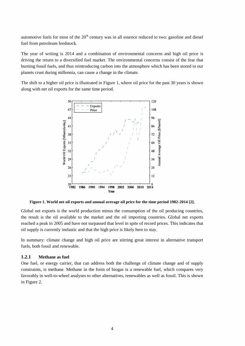
The shift to a higher oil price is illustrated in Figure 1, where oil price for the past 30 years is shown
along with net oil exports for the same time period.
Figure 1. World net oil exports and annual average oil price for the time period 1982-2014 [2].
Global net exports is the world production minus the consumption of the oil producing countries,
the result is the oil available to the market and the oil importing countries. Global net exports
reached a peak in 2005 and have not surpassed that level in spite of record prices. This indicates that
oil supply is currently inelastic and that the high price is likely here to stay.
In summary: climate change and high oil price are stirring great interest in alternative transport
fuels, both fossil and renewable.
1.2.1 Methane as fuel
One fuel, or energy carrier, that can address both the challenge of climate change and of supply
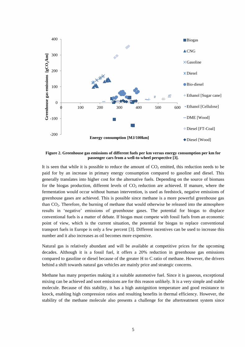
constraints, is methane. Methane in the form of biogas is a renewable fuel, which compares very
favorably in well-to-wheel analyses to other alternatives, renewables as well as fossil. This is shown
in Figure 2.
5
Figure 2. Greenhouse gas emissions of different fuels per km versus energy consumption per km for
passenger cars from a well-to-wheel perspective [3].
It is seen that while it is possible to reduce the amount of CO2 emitted, this reduction needs to be
paid for by an increase in primary energy consumption compared to gasoline and diesel. This
generally translates into higher cost for the alternative fuels. Depending on the source of biomass
for the biogas production, different levels of CO2 reduction are achieved. If manure, where the
fermentation would occur without human intervention, is used as feedstock, negative emissions of
greenhouse gases are achieved. This is possible since methane is a more powerful greenhouse gas
than CO2. Therefore, the burning of methane that would otherwise be released into the atmosphere
results in „negative‟ emissions of greenhouse gases. The potential for biogas to displace
conventional fuels is a matter of debate. If biogas must compete with fossil fuels from an economic
point of view, which is the current situation, the potential for biogas to replace conventional
transport fuels in Europe is only a few percent [3]. Different incentives can be used to increase this
number and it also increases as oil becomes more expensive.
Natural gas is relatively abundant and will be available at competitive prices for the upcoming
decades. Although it is a fossil fuel, it offers a 20% reduction in greenhouse gas emissions
compared to gasoline or diesel because of the greater H to C ratio of methane. However, the drivers
behind a shift towards natural gas vehicles are mainly price and strategic concerns.
Methane has many properties making it a suitable automotive fuel. Since it is gaseous, exceptional
mixing can be achieved and soot emissions are for this reason unlikely. It is a very simple and stable
molecule. Because of this stability, it has a high autoignition temperature and good resistance to
knock, enabling high compression ratios and resulting benefits in thermal efficiency. However, the
stability of the methane molecule also presents a challenge for the aftertreatment system since
-200
-100
0
100
200
300
400
0 100 200 300 400 500 600
Gre
enh
ou
se g
as
emis
sio
ns
[g
CO
2/k
m]
Energy consumption [MJ/100km]
Biogas
CNG
Gasoline
Diesel
Bio-diesel
Ethanol [Sugar cane]
Ethanol [Cellulose]
DME [Wood]
Diesel [FT-Coal]
Diesel [Wood]
6
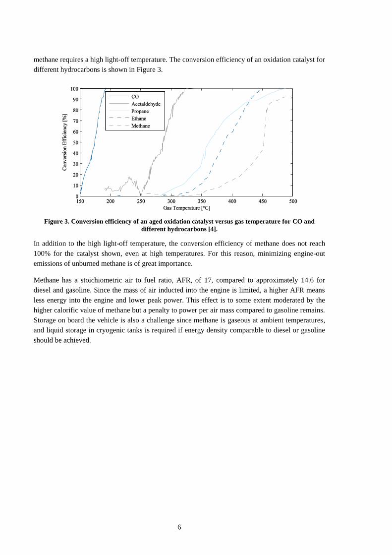
methane requires a high light-off temperature. The conversion efficiency of an oxidation catalyst for
different hydrocarbons is shown in Figure 3.
Figure 3. Conversion efficiency of an aged oxidation catalyst versus gas temperature for CO and
different hydrocarbons [4].
In addition to the high light-off temperature, the conversion efficiency of methane does not reach
100% for the catalyst shown, even at high temperatures. For this reason, minimizing engine-out
emissions of unburned methane is of great importance.
Methane has a stoichiometric air to fuel ratio, AFR, of 17, compared to approximately 14.6 for
diesel and gasoline. Since the mass of air inducted into the engine is limited, a higher AFR means
less energy into the engine and lower peak power. This effect is to some extent moderated by the
higher calorific value of methane but a penalty to power per air mass compared to gasoline remains.
Storage on board the vehicle is also a challenge since methane is gaseous at ambient temperatures,
and liquid storage in cryogenic tanks is required if energy density comparable to diesel or gasoline
should be achieved.
7
2 Emissions from combustion engines
The emissions from engines, both spark ignited, SI, and compression ignited, CI, can be divided
into two subcategories: local emissions, which negatively affect the environment close to the
emitter and global emissions, which affect the entire planet equally. Currently legislation and
certification of vehicles take only local emissions into account, and therefore these receive the most
attention from engine developers. Global emissions, the main one being CO2, are generally
analogous to poor fuel economy and are therefore minimized in order to have a competitive
product. The task when developing an engine is therefore to minimize engine fuel consumption,
development cost and production costs with the hard constraint that the legislated emission limits
need to be fulfilled. An overview of the main local- and global emissions follows.
2.1 Local emissions
2.1.1 Unburned hydrocarbons
Emissions of unburned hydrocarbons, HC, consist of fuel, partly reacted fuel and lubrication oil
which escaped combustion for various reasons. Emitted into the atmosphere, HC can cause
photochemical smog and diseases. In the SI engine where a premixed charge is compressed and
subsequently ignited, there are three main sources of HC emissions: crevice losses, adsorption and
quenching.
The largest contribution can be attributed to crevice losses; parts of the premixed charge are forced
into narrow regions, such as the piston ring pack and head gasket crevice. Conditions in these
narrow, cold, regions are unfavorable for flame propagation. As the expansion progresses and the
pressure in the cylinder drops, the unburned mixture from the crevices return to the combustion
chamber and are expelled with the exhaust gases.
Adsorption works in a similar way; at high pressure, fuel hydrocarbons are adsorbed into the oil
film on the cylinder walls and into the deposits in the combustion chamber. As the expansion
progresses and the pressure drops, the adsorption reverses, and the HC is returned to the combustion
chamber.
Finally, there is quenching; close to the cylinder wall, a boundary layer exists, with lower
temperature compared to the rest of the charge. The flame therefore quenches before it reaches the
wall, and some HC in the boundary layer may escape combustion. The extent to which quenching
affects the emissions at stoichiometric operation is considered to be small, since some of the HC
will diffuse into the hot mixture and oxidize.
Lean operation will aggravate each of these mechanisms since it leads to lower temperatures. As
dilution increases, the quench layer close to the cylinder wall will increase in thickness.
Additionally, since the temperature in the bulk gas is lowered, the fuel which diffuses into the bulk
gas from the quench layer finds it increasingly difficult to oxidize. If the mixture is sufficiently
diluted, the point is reached where partial quenching occurs, meaning that the flame is extinguished
before it has traversed the entirety of the combustion chamber. For the SI engine, the HC emissions
are handled by an oxidation catalyst and depending on the fuel used, the demands on the catalyst
differ. Since CI engines are direct injected, they are therefore not affected by any of the
8
aforementioned mechanisms. Instead, HC emissions from the CI engine are largely derived from
diesel fuel remaining in the injector sac. These contributions are small, and HC emissions are not
considered a problem for CI engines. Hydrocarbon emissions from the dual fuel engine are treated
further in section 6.1.2.
2.1.2 Carbon monoxide
Carbon monoxide, CO, is formed as an intermediate step in combustion of hydrocarbons. Failure of
CO to oxidize into CO2 can be caused by unavailability of oxygen or insufficiently high
temperatures. CO is toxic to humans and can cause symptoms ranging from light headaches to
death. In a stoichiometric engine, CO emissions will be substantial due to less than perfect mixing
and local oxygen deficits. At lean conditions, CO emissions can occur, both in the CI and the SI
engine, because of low temperatures. CO emissions are effectively handled by an oxidation catalyst
and are therefore not as problematic as emissions of HC or NOx.
2.1.3 Nitrogen oxides
Mono-nitrogen oxides, NO and NO2, commonly referred to as NOx, are formed through various
mechanisms, where atmospheric nitrogen, or nitrogen from the fuel, is fused with oxygen with the
aid of high temperatures. NOx emissions can cause respiratory diseases. At ground level NOx
contributes to the formation of ozone while, paradoxically, it destroys the ozone at high altitudes
damaging the ozone layer.
The most influential NOx producing mechanism in combustion engines is believed to be thermal
NOx. This route was proposed by Zel‟dovich in 1948 and has since been appended to. The extended
Zel‟dovich mechanism consists of three reversible reactions:
1. O• + N2 ←k1→ NO + N•
2. N• + O2 ←k2→ NO + O•
3. N• + OH ←k3→ NO + H•
The name thermal NOx refers to the high activation energy of the first, rate-limiting reaction which
makes this mechanism highly temperature dependent. The rate constants in the mechanism have
been revised recently and substantially increased. According to current theory, thermal NOx is
responsible for 90-95% of the NOx emissions from combustion engines [5].
Prompt NOx, or Fenimore NOx, is a mechanism where atmospheric N2 reacts with CH radicals. Due
to the need for these radicals, prompt NOx is dependent on locally fuel rich areas and decreases
quickly at lean mixtures. At lean conditions and high pressures, the first reaction of the Zel‟dovich
mechanism can be stabilized through collision with a third party so that N2O is formed instead of
NO; the N2O is then oxidized to 2 NO molecules. Both Fenimore NOx and the N2O route are
characterized by large uncertainties. Finally, there is the possibility for nitrogen bound in the fuel to
form NO, however, engine fuels contain very little N2, and this contribution is therefore considered
irrelevant.
Due to the strong temperature dependence of the Zel‟dovich mechanism, NOx formation in engines
is dependent on the conditions in the hottest parts of the combustion chamber. In the SI engine, this
corresponds to the volume around the spark plug, which burns first and is further compressed by the
9
burning of the remainder of the charge. In CI engines, most of the NOx forms in the edge of the fuel
plume where conditions are close to stoichiometry.
2.2 Global emissions
2.2.1 Carbon dioxide
Carbon dioxide, CO2, is the inevitable byproduct of hydrocarbon combustion. It is an inert gas, not
harmful to plants or animals. It is, however, a greenhouse gas. Burning fossil fuels, stored beneath
the ground during past millennia, increases the concentration of CO2 in the atmosphere. As the
concentration of CO2 increases, more of the sun‟s heat is retained, potentially warming the planet
and changing the climate.
2.2.2 Methane
Methane, CH4, while a hydrocarbon by definition, it is also inert, and does not contribute to smog
production or respiratory diseases. However, methane is a very potent greenhouse gas, and if not
carefully addressed, methane slip from engines can nullify any environmental benefits of switching
from gasoline or diesel.
10
3 Overview of methane engines
3.1 Methane monofuel engines
Methane is mainly used in SI engines. In light duty applications, these engines are usually bi-fuel
engines; they must be able to operate on gasoline fuel as well. This limits the compression ratio, and
effectively limits the efficiency of the engine as well. For medium and heavy duty applications, SI
gas engines are typically mono-fuel, meaning that they can be optimized for methane operation,
providing better efficiency. These engines still suffer from the known Achilles heel of the Otto
engines, pumping losses and poor part load efficiency. The pumping losses can be addressed to
some extent, by running the engine lean and by adding EGR. Lean operation of an SI engine is the
source of many complications since the three way catalyst can no longer be used to reduce NOx and
a lot of strain is put on the ignition system.
Examples of mono fuel CI engines operating on methane exist. These are currently not widespread
due to the high autoignition temperature and corresponding demand for compression ratio and
ignition aids.
3.2 Methane dual fuel engines
One solution to using methane in a CI engine is to introduce a pilot-fuel with higher cetane
number ,which initiates combustion and ignites the methane, thus giving rise to the methane-diesel
dual fuel, DDF, engine. Work is currently carried out, both in the field of direct injected DDF, as
well as port injected DDF.
Direct injected DDF involves a special DI injector, which handles both the diesel and the methane
fuel. A small pilot amount of diesel fuel is injected ahead of the main injection to raise the
temperature and allow for ignition of the methane [6]. The methane is then injected and burns in a
diffusion flame, similar to diesel combustion. This concept enables unthrottled operation with little
methane slip, but particles and NOx present a problem. The system is also complex and expensive,
and it is not possible to run the vehicle on diesel only, so fuel flexibility is lost.
In port injected DDF, the methane is injected into the intake manifold and is premixed with the air
during induction and compression. A small diesel pilot is used to initiate combustion. The work
presented in this thesis focuses solely on port injected DDF, and henceforth this is what is referred
to when the acronym DDF is used. Port injected DDF has the potential to maintain diesel capability
in case methane is unavailable. This is an important factor when bringing the technology to market.
11
4 The dual fuel engine
In this chapter, the port injected DDF engine is described in further detail. An introduction to DDF
combustion is given, followed by an overview of the main challenges involved in dual fuel
operation. These challenges comprise the objectives of the thesis.
4.1 Introduction to DDF combustion
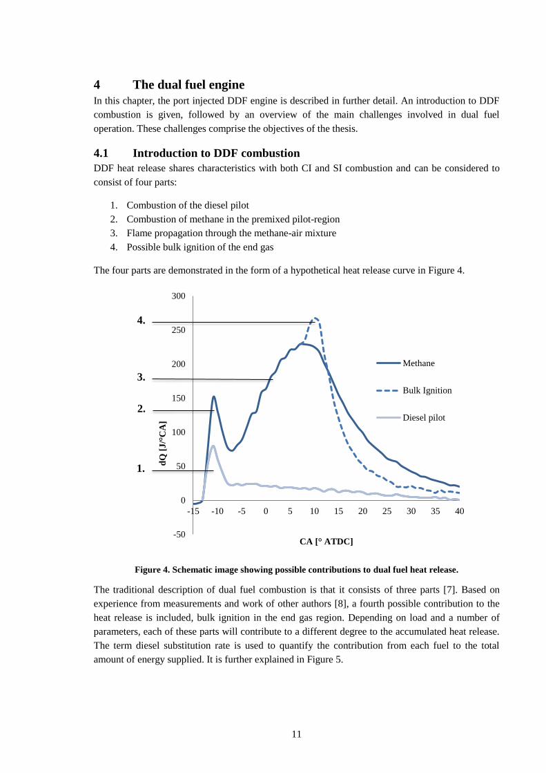
DDF heat release shares characteristics with both CI and SI combustion and can be considered to
consist of four parts:
1. Combustion of the diesel pilot
2. Combustion of methane in the premixed pilot-region
3. Flame propagation through the methane-air mixture
4. Possible bulk ignition of the end gas
The four parts are demonstrated in the form of a hypothetical heat release curve in Figure 4.
Figure 4. Schematic image showing possible contributions to dual fuel heat release.
The traditional description of dual fuel combustion is that it consists of three parts [7]. Based on
experience from measurements and work of other authors [8], a fourth possible contribution to the
heat release is included, bulk ignition in the end gas region. Depending on load and a number of
parameters, each of these parts will contribute to a different degree to the accumulated heat release.
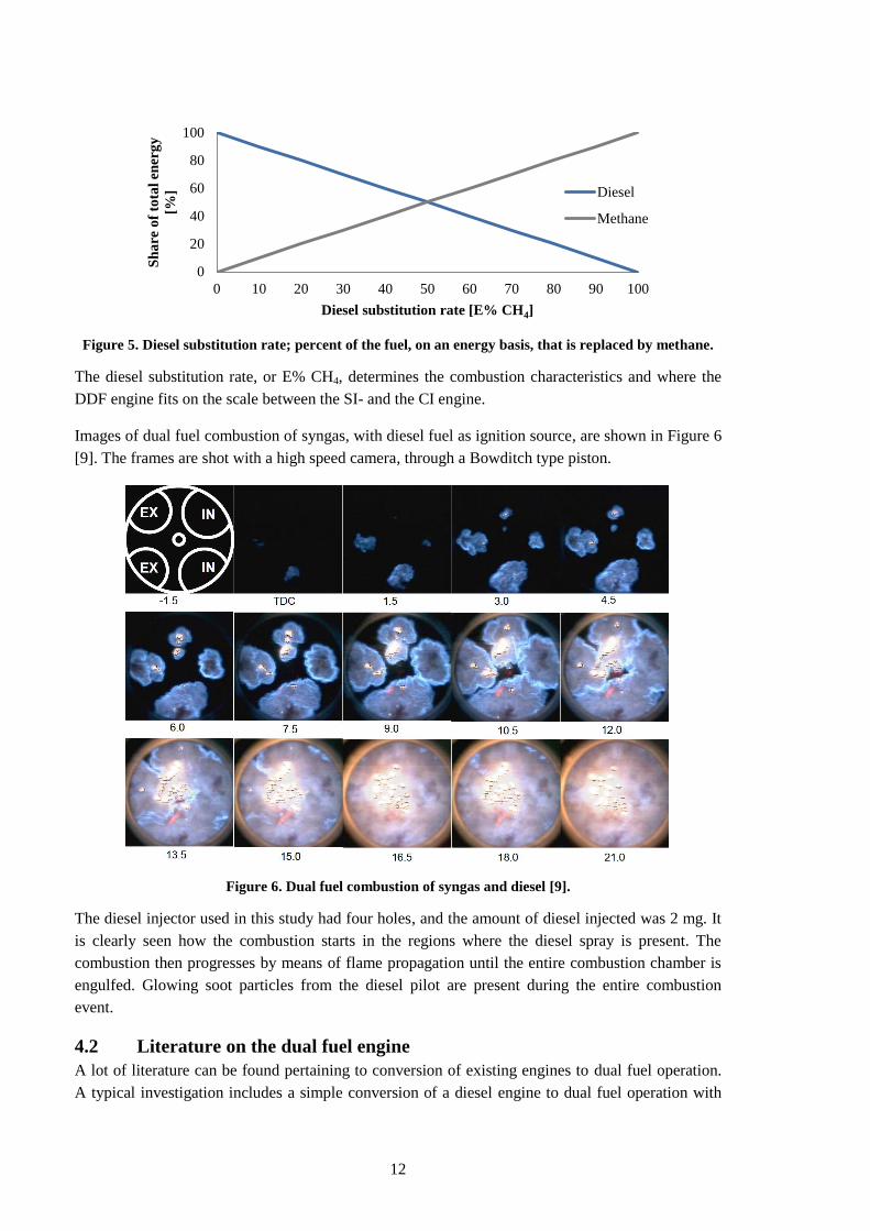
The term diesel substitution rate is used to quantify the contribution from each fuel to the total
amount of energy supplied. It is further explained in Figure 5.
-50
0
50
100
150
200
250
300
-15 -10 -5 0 5 10 15 20 25 30 35 40
dQ
[J
/°C
A]
CA [° ATDC]
Methane
Bulk Ignition
Diesel pilot
1.
2.
3.
4.
12
Figure 5. Diesel substitution rate; percent of the fuel, on an energy basis, that is replaced by methane.
The diesel substitution rate, or E% CH4, determines the combustion characteristics and where the
DDF engine fits on the scale between the SI- and the CI engine.
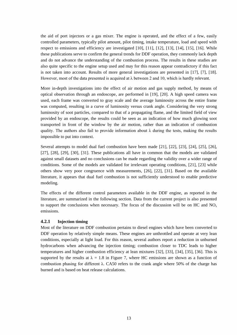
Images of dual fuel combustion of syngas, with diesel fuel as ignition source, are shown in Figure 6
[9]. The frames are shot with a high speed camera, through a Bowditch type piston.
Figure 6. Dual fuel combustion of syngas and diesel [9].
The diesel injector used in this study had four holes, and the amount of diesel injected was 2 mg. It
is clearly seen how the combustion starts in the regions where the diesel spray is present. The
combustion then progresses by means of flame propagation until the entire combustion chamber is
engulfed. Glowing soot particles from the diesel pilot are present during the entire combustion
event.
4.2 Literature on the dual fuel engine
A lot of literature can be found pertaining to conversion of existing engines to dual fuel operation.
A typical investigation includes a simple conversion of a diesel engine to dual fuel operation with
0
20
40
60
80
100
0 10 20 30 40 50 60 70 80 90 100
Sh
are
of
tota
l en
erg
y
[%]
Diesel substitution rate [E% CH4]
Diesel
Methane
13
the aid of port injectors or a gas mixer. The engine is operated, and the effect of a few, easily
controlled parameters, typically pilot amount, pilot timing, intake temperature, load and speed with
respect to emissions and efficiency are investigated [10], [11], [12], [13], [14], [15], [16]. While
these publications serve to confirm the general trends for DDF operation, they commonly lack depth
and do not advance the understanding of the combustion process. The results in these studies are
also quite specific to the engine setup used and may for this reason appear contradictory if this fact
is not taken into account. Results of more general investigations are presented in [17], [7], [18].
However, most of the data presented is acquired at λ between 2 and 10, which is hardly relevant.
More in-depth investigations into the effect of air motion and gas supply method, by means of
optical observation through an endoscope, are performed in [19], [20]. A high speed camera was
used, each frame was converted to gray scale and the average luminosity across the entire frame
was computed, resulting in a curve of luminosity versus crank angle. Considering the very strong
luminosity of soot particles, compared to that of a propagating flame, and the limited field of view
provided by an endoscope, the results could be seen as an indication of how much glowing soot
transported in front of the window by the air motion, rather than an indication of combustion
quality. The authors also fail to provide information about λ during the tests, making the results
impossible to put into context.
Several attempts to model dual fuel combustion have been made [21], [22], [23], [24], [25], [26],
[27], [28], [29], [30], [31]. These publications all have in common that the models are validated
against small datasets and no conclusions can be made regarding the validity over a wider range of
conditions. Some of the models are validated for irrelevant operating conditions, [21], [23] while
others show very poor congruence with measurements, [26], [22], [31]. Based on the available
literature, it appears that dual fuel combustion is not sufficiently understood to enable predictive
modeling.
The effects of the different control parameters available in the DDF engine, as reported in the
literature, are summarized in the following section. Data from the current project is also presented
to support the conclusions when necessary. The focus of the discussion will be on HC and NOx
emissions.
4.2.1 Injection timing
Most of the literature on DDF combustion pertains to diesel engines which have been converted to
DDF operation by relatively simple means. These engines are unthrottled and operate at very lean
conditions, especially at light load. For this reason, several authors report a reduction in unburned
hydrocarbons when advancing the injection timing; combustion closer to TDC leads to higher
temperatures and higher combustion efficiency at lean mixtures [32], [33], [34], [35], [36]. This is
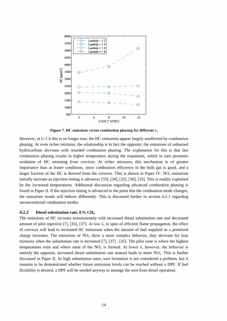
supported by the results at λ = 1.8 in Figure 7, where HC emissions are shown as a function of
combustion phasing for different λ. CA50 refers to the crank angle where 50% of the charge has
burned and is based on heat release calculations.
14
Figure 7. HC emissions versus combustion phasing for different λ.
However, at λ=1.6 this is no longer true; the HC emissions appear largely unaffected by combustion
phasing. At even richer mixtures, the relationship is in fact the opposite; the emissions of unburned
hydrocarbons decrease with retarded combustion phasing. The explanation for this is that late
combustion phasing results in higher temperature during the expansion, which in turn promotes
oxidation of HC returning from crevices. At richer mixtures, this mechanism is of greater
importance than at leaner conditions, since combustion efficiency in the bulk gas is good, and a
larger fraction of the HC is derived from the crevices. This is shown in Paper IV. NOx emissions
initially increase as injection timing is advances [33], [34], [32], [36], [35]. This is readily explained
by the increased temperatures. Additional discussion regarding advanced combustion phasing is
found in Paper II. If the injection timing is advanced to the point that the combustion mode changes,
the emissions trends will behave differently. This is discussed further in section 6.2.1 regarding
unconventional combustion modes.
4.2.2 Diesel substitution rate, E% CH4
The emissions of HC increase monotonously with increased diesel substitution rate and decreased
amount of pilot injection [7], [35], [37]. At low λ, in spite of efficient flame propagation, the effect
of crevices will lead to increased HC emissions when the amount of fuel supplied as a premixed
charge increases. The emissions of NOx show a more complex behavior, they decrease for lean
mixtures when the substitution rate is increased [7], [37] , [35]. The pilot zone is where the highest
temperatures exist and where most of the NOx is formed. At lower λ, however, the behavior is
entirely the opposite, increased diesel substitution rate instead leads to more NOx. This is further
discussed in Paper II. At high substitution rates, soot formation is not considered a problem, but it
remains to be demonstrated whether future emissions levels can be reached without a DPF. If fuel
flexibility is desired, a DPF will be needed anyway to manage the soot from diesel operation.
15
4.2.3 Inlet temperature
Increased inlet temperature enhances the flame propagation and reduces the emissions of HC and
CO [7]. Predictably, it also leads to higher emissions of NOx. High inlet temperature increases the
likelihood of knock and pre-ignition at high load, and it is therefore something which can be utilized
primarily at light load to reduce the amount of throttling needed. Results from test runs with raised
intake temperature and further discussion is located in Paper II.
4.2.4 EGR
EGR dilutes the mixture and lowers the compression- and combustion temperature. From the
dilution, the O2 concentration is reduced. The reduction in temperature and O2 concentration affects
combustion efficiency negatively. For this reason, CO and HC emissions increase. It also lowers the
combustion temperature, which drastically reduces the formation of NOx and reduces the risk of
pre-ignitions [32], [38], [39]. The strong suppressing effect of EGR on pre-ignitions has been shown
in this project, and cooled EGR may be a tool needed to reach desired power density. Hot EGR
combines the NOx-reducing effect with the improved flame propagation from high inlet
temperature, allowing a simultaneous reduction of HC, CO and NOx [33]. The use of EGR to reach
stoichiometric conditions, while minimizing throttling loss, is also a strong possibility in the DDF
engine, thus enabling a very cost efficient aftertreatment system through the use of a three-way-
catalyst [38]. The EGR tolerance is very large compared to an SI engine due to the powerful
ignition source. EGR as a tool to reach stoichiometry is discussed further in Paper II.
4.2.5 Diesel common rail pressure
The diesel common rail pressure has a small effect on combustion, with the notable exception that
reduced common rail pressure helps facilitate reliable pilot injection at operating points with
substantial throttling. Results from this project show that, reducing the injection pressure decreases
the dispersion of the diesel pilot and enables further throttling, with maintained diesel ignition. This
is illustrated in Figure 8.
16
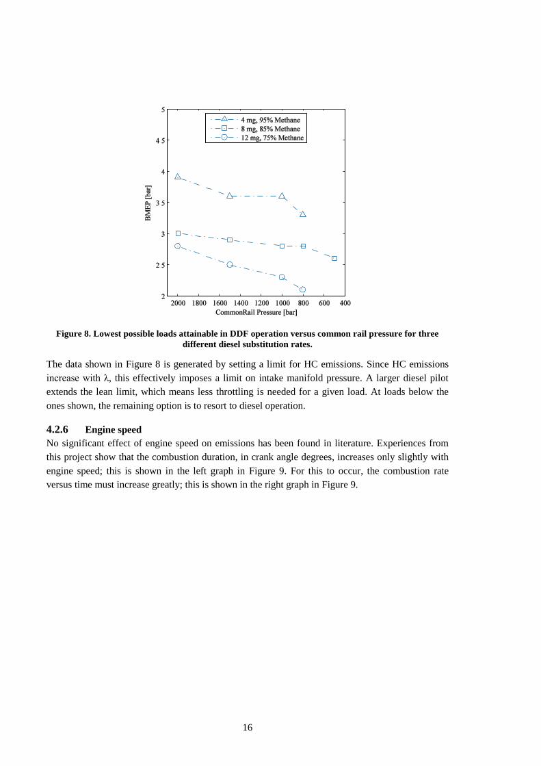
Figure 8. Lowest possible loads attainable in DDF operation versus common rail pressure for three
different diesel substitution rates.
The data shown in Figure 8 is generated by setting a limit for HC emissions. Since HC emissions
increase with λ, this effectively imposes a limit on intake manifold pressure. A larger diesel pilot
extends the lean limit, which means less throttling is needed for a given load. At loads below the
ones shown, the remaining option is to resort to diesel operation.
4.2.6 Engine speed
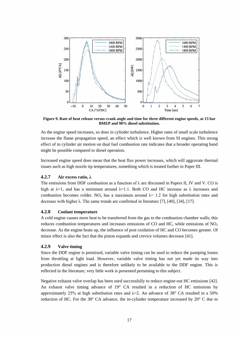
No significant effect of engine speed on emissions has been found in literature. Experiences from
this project show that the combustion duration, in crank angle degrees, increases only slightly with
engine speed; this is shown in the left graph in Figure 9. For this to occur, the combustion rate
versus time must increase greatly; this is shown in the right graph in Figure 9.
17
Figure 9. Rate of heat release versus crank angle and time for three different engine speeds, at 13 bar
BMEP and 98% diesel substitution.
As the engine speed increases, so does in cylinder turbulence. Higher rates of small scale turbulence
increase the flame propagation speed, an effect which is well known from SI engines. This strong
effect of in cylinder air motion on dual fuel combustion rate indicates that a broader operating band
might be possible compared to diesel operation.
Increased engine speed does mean that the heat flux power increases, which will aggravate thermal
issues such as high nozzle tip temperatures, something which is treated further in Paper III.
4.2.7 Air excess ratio, λ
The emissions from DDF combustion as a function of λ are discussed in Papers II, IV and V. CO is
high at λ=1, and has a minimum around λ=1.1. Both CO and HC increase as λ increases and
combustion becomes colder. NOx has a maximum around λ= 1.2 for high substitution rates and
decrease with higher λ. The same trends are confirmed in literature [7], [40], [34], [17].
4.2.8 Coolant temperature
A cold engine causes more heat to be transferred from the gas to the combustion chamber walls; this
reduces combustion temperatures and increases emissions of CO and HC, while emissions of NOx
decrease. As the engine heats up, the influence of post oxidation of HC and CO becomes greater. Of
minor effect is also the fact that the piston expands and crevice volumes decrease [41].
4.2.9 Valve timing
Since the DDF engine is premixed, variable valve timing can be used to reduce the pumping losses
from throttling at light load. However, variable valve timing has not yet made its way into
production diesel engines and is therefore unlikely to be available to the DDF engine. This is
reflected in the literature; very little work is presented pertaining to this subject.
Negative exhaust valve overlap has been used successfully to reduce engine-out HC emissions [42].
An exhaust valve timing advance of 19° CA resulted in a reduction of HC emissions by
approximately 25% at high substitution rates and λ=2. An advance of 38° CA resulted in a 50%
reduction of HC. For the 38° CA advance, the in-cylinder temperature increased by 20° C due to
18
increased amount of residual gases. The increase in temperature can be expected to improve
combustion efficiency and probably accounts for some of the 50% reduction. However, since the
19° CA advance had the same in-cylinder temperature at IVC, the reduction in HC could be from
trapping HC emerging from crevices late during the expansion and during the blowdown. Negative
valve overlap with fixed cams would likely severely limit maximum load due to knock and is for
this reason unlikely to be utilized in production.
The possibility to reduce the effective compression ratio at high load through Miller timing, and
thus mitigate knock and pre-ignition, is a promising application for a variable valve train in the
DDF engine.
4.2.10 Summary of influence of control parameters
A rule of thumb is that parameter changes which increase combustion temperature decrease HC and
CO emissions but increase the emissions of NOx. Hot EGR is the exception to the rule since it has
the potential to simultaneously reduce HC, CO and NOx.
4.3 Objectives and challenges
Dual fuel combustion is not a mature technology when compared to CI and SI combustion. Because
of this, it is expected that not all challenges and limitations have been encountered and documented,
much less fully understood. This project is preceded by student projects. Based on information from
those projects, the principal challenges which hinder the introduction of this engine type are
hydrocarbon emissions and knock. The main focus of the project is therefore to investigate these
two challenges and propose solutions, but also to identify, investigate and attempt to overcome
limits to dual fuel operation which are not yet known. For this reason, a screening of the engine
operating range, where the most influential control parameters are varied, was carried out during the
initial phase of the project. The results from this screening are presented in Paper I and Paper II.
In Paper I, operating conditions were carried over from a production diesel engine, and different
injection strategies for the diesel injection during DDF operation were evaluated. It was found that
injection strategies were not sufficient to enable the conversion to dual fuel operation with
acceptable emissions. Further investigations were carried out under the assumption that a throttle
was available and that λ-control, similar to SI engines, would be required. Several control
parameters were evaluated, mainly with regards to their influence on the lean limit for operation.
The findings from this investigation were published in Paper II. Based on these screenings and on
available literature, the main challenges of CNG-diesel dual fuel operation are:
HC emissions:
▫ At light load, unthrottled operation at high λ will result in poor flame propagation and
incomplete combustion. Different injection strategies for the diesel fuel are known to
affect lean performance. However, how these compare to baseline diesel and standard
DDF operation with regards to emissions, efficiency and stability is not fully
investigated. Additionally, the potential of in-cylinder air motion to improve the
tolerance for lean operation is largely unknown. These topics were investigated, and the
results are presented in Papers I and V.
19
▫ Methane slip from crevices needs to be managed regardless of load. The contribution to
total HC emissions from crevices, during lean operation and using methane as fuel, is
not known. Furthermore, the effect, on the relative importance of different HC-sources,
from varying engine operating conditions, is also unknown. A thorough investigation of
methane slip from crevices is presented in Paper IV.
Thermal issues
▫ At high load, overheating of the diesel injector tip is an issue which may lead to nozzle
hole coking and problems with durability. Currently no work is fund which addresses
these issues. The temperatures which occur are unknown, as is the effect that these
temperatures have on rate of nozzle hole coking. These related issues were investigated
in Papers III and VI.
Pre-ignitions & knock
▫ From the first screenings it was found that pre-ignitions impose stricter limits to engine
operation than knock. The root cause for pre-ignitions at high compression ratios using
methane fuel is unknown. Investigations focused on pre-ignition and knock have been
performed since and are presented in this thesis but have not yet been published in other
forums.
In addition to the Papers; the current state of each of these phenomena and the contribution from
this project to their understanding will be explored in further detail in chapter 6, Results.
20
5 Experimental setup
This section details the experimental setup used. If no other information is given, all data shown in
this publication is recorded using this equipment.
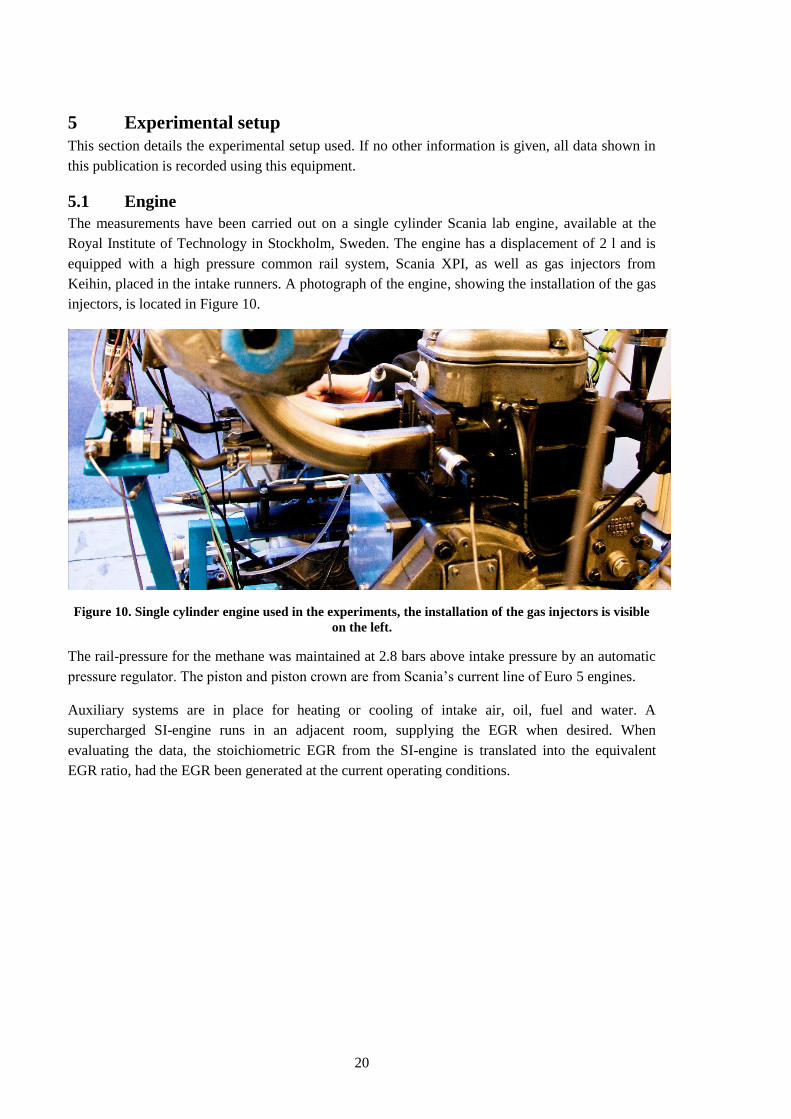
5.1 Engine
The measurements have been carried out on a single cylinder Scania lab engine, available at the
Royal Institute of Technology in Stockholm, Sweden. The engine has a displacement of 2 l and is
equipped with a high pressure common rail system, Scania XPI, as well as gas injectors from
Keihin, placed in the intake runners. A photograph of the engine, showing the installation of the gas
injectors, is located in Figure 10.
Figure 10. Single cylinder engine used in the experiments, the installation of the gas injectors is visible
on the left.
The rail-pressure for the methane was maintained at 2.8 bars above intake pressure by an automatic
pressure regulator. The piston and piston crown are from Scania‟s current line of Euro 5 engines.
Auxiliary systems are in place for heating or cooling of intake air, oil, fuel and water. A
supercharged SI-engine runs in an adjacent room, supplying the EGR when desired. When
evaluating the data, the stoichiometric EGR from the SI-engine is translated into the equivalent
EGR ratio, had the EGR been generated at the current operating conditions.
21
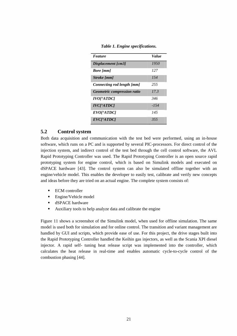
Table 1. Engine specifications.
Feature Value
Displacement [cm3] 1950
Bore [mm] 127
Stroke [mm] 154
Connecting rod length [mm] 255
Geometric compression ratio 17.3
IVO[°ATDC] 346
IVC[°ATDC] -154
EVO[°ATDC] 145
EVC[°ATDC] 355
5.2 Control system
Both data acquisition and communication with the test bed were performed, using an in-house
software, which runs on a PC and is supported by several PIC-processors. For direct control of the
injection system, and indirect control of the test bed through the cell control software, the AVL
Rapid Prototyping Controller was used. The Rapid Prototyping Controller is an open source rapid
prototyping system for engine control, which is based on Simulink models and executed on
dSPACE hardware [43]. The control system can also be simulated offline together with an
engine/vehicle model. This enables the developer to easily test, calibrate and verify new concepts
and ideas before they are tried on an actual engine. The complete system consists of:
ECM controller
Engine/Vehicle model
dSPACE hardware
Auxiliary tools to help analyze data and calibrate the engine
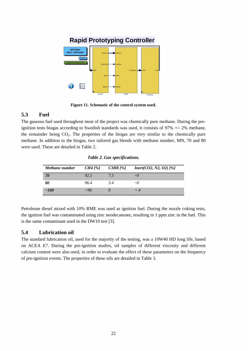
Figure 11 shows a screenshot of the Simulink model, when used for offline simulation. The same
model is used both for simulation and for online control. The transition and variant management are
handled by GUI and scripts, which provide ease of use. For this project, the drive stages built into
the Rapid Prototyping Controller handled the Keihin gas injectors, as well as the Scania XPI diesel
injector. A rapid self- tuning heat release script was implemented into the controller, which
calculates the heat release in real-time and enables automatic cycle-to-cycle control of the
combustion phasing [44].
22
Figure 11. Schematic of the control system used.
5.3 Fuel
The gaseous fuel used throughout most of the project was chemically pure methane. During the pre-
ignition tests biogas according to Swedish standards was used, it consists of 97% +/- 2% methane,
the remainder being CO2. The properties of the biogas are very similar to the chemically pure
methane. In addition to the biogas, two tailored gas blends with methane number, MN, 70 and 80
were used. These are detailed in Table 2.
Table 2. Gas specifications.
Methane number CH4 [%] C3H8 [%] Inert(CO2, N2, O2) [%]
70 92.5 7.5 ~0
80 96.4 3.4 ~0
~100 >96 0 < 4
Petroleum diesel mixed with 10% RME was used as ignition fuel. During the nozzle coking tests,
the ignition fuel was contaminated using zinc neodecanoate, resulting in 1 ppm zinc in the fuel. This
is the same contaminant used in the DW10 test [3].
5.4 Lubrication oil
The standard lubrication oil, used for the majority of the testing, was a 10W40 HD long life, based
on ACEA E7. During the pre-ignition studies, oil samples of different viscosity and different
calcium content were also used, in order to evaluate the effect of these parameters on the frequency
of pre-ignition events. The properties of these oils are detailed in Table 3.
RAPTORRapid Prototyping Controller
Check for broken links
Scope
SETTINGS:
Base_Calibration
RTI Data
ECM SIG
Outputs
SNS
Sensors
CombTrig
10ms
2p5ms
Inputs
Sensors
LowRes
10ms
2p5ms
Actuators
ECM
23
Table 3. Oil formulations.
Oil no. Ca Zn Ash [%]
1 Scania 10W40 4300 1300 1.9
2 E4 10W40 4870 1360 1.9
3 E6 5W30 2330 790 0.99
4 NA 15W40 0 - 0
5 E4 5W30 4920 1340 1.9
6 E6 10W40 2350 820 0.98
7 E4 10W40 Repeat 4870 1360 1.9
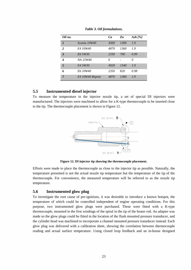
5.5 Instrumented diesel injector
To measure the temperature in the injector nozzle tip, a set of special DI injectors were
manufactured. The injectors were machined to allow for a K-type thermocouple to be inserted close
to the tip. The thermocouple placement is shown in Figure 12.
Figure 12. DI injector tip showing the thermocouple placement.
Efforts were made to place the thermocouple as close to the injector tip as possible. Naturally, the
temperature presented is not the actual nozzle tip temperature but the temperature of the tip of the
thermocouple. For convenience, the measured temperature will be referred to as the nozzle tip
temperature.
5.6 Instrumented glow plug
To investigate the root cause of pre-ignitions, it was desirable to introduce a known hotspot, the
temperature of which could be controlled independent of engine operating conditions. For this
purpose, two instrumented glow plugs were purchased. These were fitted with a K-type
thermocouple, mounted in the first windings of the spiral in the tip of the heater rod. An adapter was
made so the glow plugs could be fitted in the location of the flush mounted pressure transducer, and
the cylinder head was machined to incorporate a channel mounted pressure transducer instead. Each
glow plug was delivered with a calibration sheet, showing the correlation between thermocouple
reading and actual surface temperature. Using closed loop feedback and an in-house designed
24
driver, the surface temperature of the glow plug could then be controlled in the interval 500°C-
1060°C.
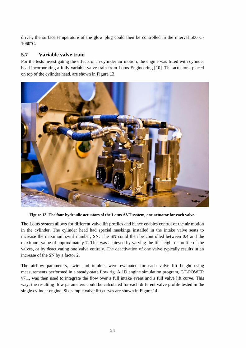
5.7 Variable valve train
For the tests investigating the effects of in-cylinder air motion, the engine was fitted with cylinder
head incorporating a fully variable valve train from Lotus Engineering [10]. The actuators, placed
on top of the cylinder head, are shown in Figure 13.
Figure 13. The four hydraulic actuators of the Lotus AVT system, one actuator for each valve.
The Lotus system allows for different valve lift profiles and hence enables control of the air motion
in the cylinder. The cylinder head had special maskings installed in the intake valve seats to
increase the maximum swirl number, SN. The SN could then be controlled between 0.4 and the
maximum value of approximately 7. This was achieved by varying the lift height or profile of the
valves, or by deactivating one valve entirely. The deactivation of one valve typically results in an
increase of the SN by a factor 2.
The airflow parameters, swirl and tumble, were evaluated for each valve lift height using
measurements performed in a steady-state flow rig. A 1D engine simulation program, GT-POWER
v7.1, was then used to integrate the flow over a full intake event and a full valve lift curve. This
way, the resulting flow parameters could be calculated for each different valve profile tested in the
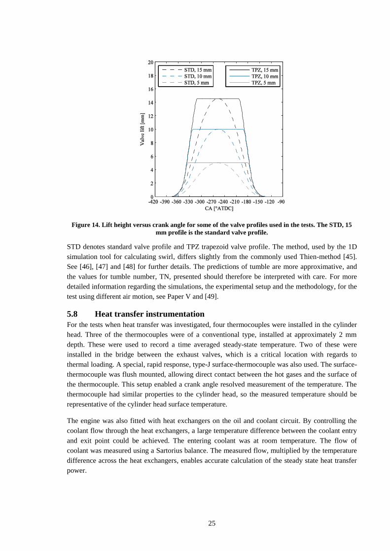
single cylinder engine. Six sample valve lift curves are shown in Figure 14.
25
Figure 14. Lift height versus crank angle for some of the valve profiles used in the tests. The STD, 15
mm profile is the standard valve profile.
STD denotes standard valve profile and TPZ trapezoid valve profile. The method, used by the 1D
simulation tool for calculating swirl, differs slightly from the commonly used Thien-method [45].
See [46], [47] and [48] for further details. The predictions of tumble are more approximative, and
the values for tumble number, TN, presented should therefore be interpreted with care. For more
detailed information regarding the simulations, the experimental setup and the methodology, for the
test using different air motion, see Paper V and [49].
5.8 Heat transfer instrumentation
For the tests when heat transfer was investigated, four thermocouples were installed in the cylinder
head. Three of the thermocouples were of a conventional type, installed at approximately 2 mm
depth. These were used to record a time averaged steady-state temperature. Two of these were
installed in the bridge between the exhaust valves, which is a critical location with regards to
thermal loading. A special, rapid response, type-J surface-thermocouple was also used. The surface-
thermocouple was flush mounted, allowing direct contact between the hot gases and the surface of
the thermocouple. This setup enabled a crank angle resolved measurement of the temperature. The
thermocouple had similar properties to the cylinder head, so the measured temperature should be
representative of the cylinder head surface temperature.
The engine was also fitted with heat exchangers on the oil and coolant circuit. By controlling the
coolant flow through the heat exchangers, a large temperature difference between the coolant entry
and exit point could be achieved. The entering coolant was at room temperature. The flow of
coolant was measured using a Sartorius balance. The measured flow, multiplied by the temperature
difference across the heat exchangers, enables accurate calculation of the steady state heat transfer
power.
26
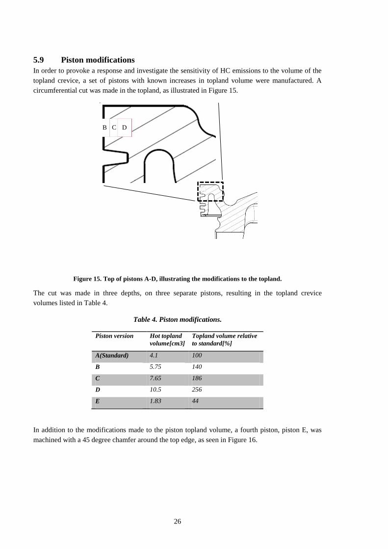
5.9 Piston modifications
In order to provoke a response and investigate the sensitivity of HC emissions to the volume of the
topland crevice, a set of pistons with known increases in topland volume were manufactured. A
circumferential cut was made in the topland, as illustrated in Figure 15.
Figure 15. Top of pistons A-D, illustrating the modifications to the topland.
The cut was made in three depths, on three separate pistons, resulting in the topland crevice
volumes listed in Table 4.
Table 4. Piston modifications.
Piston version Hot topland
volume[cm3] Topland volume relative
to standard[%]
A(Standard) 4.1 100
B 5.75 140
C 7.65 186
D 10.5 256
E 1.83 44
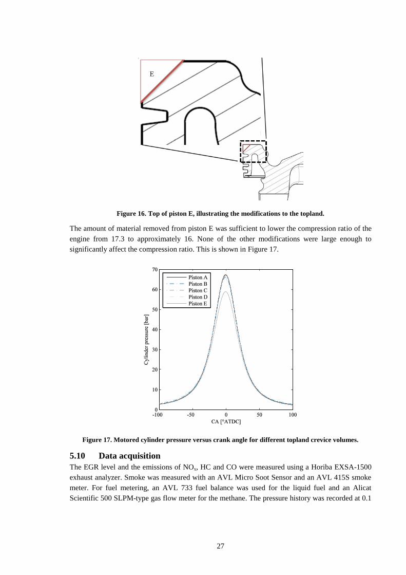
In addition to the modifications made to the piston topland volume, a fourth piston, piston E, was
machined with a 45 degree chamfer around the top edge, as seen in Figure 16.
B C D
27
Figure 16. Top of piston E, illustrating the modifications to the topland.
The amount of material removed from piston E was sufficient to lower the compression ratio of the
engine from 17.3 to approximately 16. None of the other modifications were large enough to
significantly affect the compression ratio. This is shown in Figure 17.
Figure 17. Motored cylinder pressure versus crank angle for different topland crevice volumes.
5.10 Data acquisition
The EGR level and the emissions of NOx, HC and CO were measured using a Horiba EXSA-1500
exhaust analyzer. Smoke was measured with an AVL Micro Soot Sensor and an AVL 415S smoke
meter. For fuel metering, an AVL 733 fuel balance was used for the liquid fuel and an Alicat
Scientific 500 SLPM-type gas flow meter for the methane. The pressure history was recorded at 0.1
28
CA increments, using AVL QC32D and AVL GH12D pressure transducers and a Kistler 5011
charge amplifier.
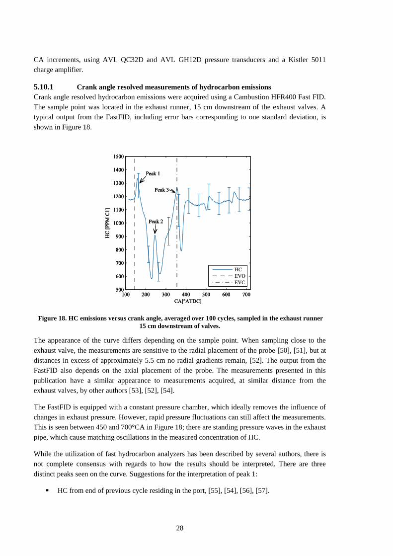
5.10.1 Crank angle resolved measurements of hydrocarbon emissions
Crank angle resolved hydrocarbon emissions were acquired using a Cambustion HFR400 Fast FID.
The sample point was located in the exhaust runner, 15 cm downstream of the exhaust valves. A
typical output from the FastFID, including error bars corresponding to one standard deviation, is
shown in Figure 18.
Figure 18. HC emissions versus crank angle, averaged over 100 cycles, sampled in the exhaust runner
15 cm downstream of valves.
The appearance of the curve differs depending on the sample point. When sampling close to the
exhaust valve, the measurements are sensitive to the radial placement of the probe [50], [51], but at
distances in excess of approximately 5.5 cm no radial gradients remain, [52]. The output from the
FastFID also depends on the axial placement of the probe. The measurements presented in this
publication have a similar appearance to measurements acquired, at similar distance from the
exhaust valves, by other authors [53], [52], [54].
The FastFID is equipped with a constant pressure chamber, which ideally removes the influence of
changes in exhaust pressure. However, rapid pressure fluctuations can still affect the measurements.
This is seen between 450 and 700°CA in Figure 18; there are standing pressure waves in the exhaust
pipe, which cause matching oscillations in the measured concentration of HC.
While the utilization of fast hydrocarbon analyzers has been described by several authors, there is
not complete consensus with regards to how the results should be interpreted. There are three
distinct peaks seen on the curve. Suggestions for the interpretation of peak 1:
HC from end of previous cycle residing in the port, [55], [54], [56], [57].
29
HC from quench layers and crevices close to exhaust valve, [55], [53], [52], [58], [54], [59],
[60], [61].
Considering the pressure sensitivity of the FastFID, a plausible third explanation for the first peak
can be postulated: a combination of HC from the previous cycle, intensified by the pressure increase
from the blowdown pulse.
The second peak is more controversial; some authors claim that it is influenced by changes to the
ring pack [55]. According to this reasoning, the second peak would be a result of turbulent release
of HC trapped in second land. However, measurements carried out during the work presented in
Paper IV, where the ring gap of the second piston ring was increased, show no influence on the
second peak, making this theory unlikely.
Others authors postulate that the reverse flow, which can occur immediately following the
blowdown pulse, causes some of the HC from peak 1 to be measured twice [53], [52], [61]. This
theory has further support as [56] show a correlation between the height of the second peak and the
level of HC present in the port before EVO.
Regarding the third peak, there seems to be a general agreement that it is the result of HC from
piston crevices. These hydrocarbons have been deposited along the liner, by the downward motion
of the piston during the expansion stroke, and are subsequently collected again in a vortex at the
edge of the piston during the exhaust stroke [41] [55]. This is also supported by the tests with
increased second ring ring-gap, which have been previously mentioned. Increasing the ring-gap,
causing HC in second land to flow into the crank case to a greater extent, instead of back into the
combustion chamber, caused the third peak to decrease in magnitude.
Based on the above reasoning, the general conclusion regarding crank angle resolved HC
measurements is that HC expelled late during the exhaust stroke can be attributed to piston crevices,
and HC expelled during the early part of the exhaust stroke to other sources.
30
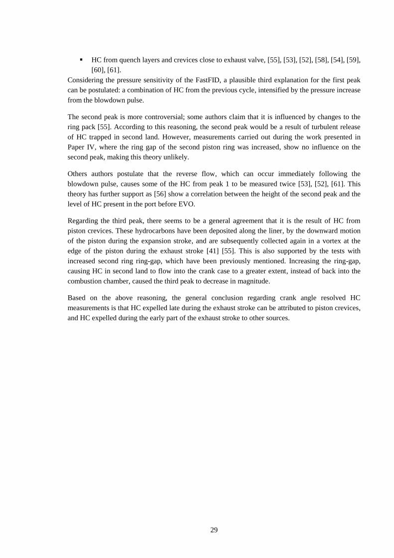
6 Results
The results chapter is organized according to Figure 19, where the challenges of dual fuel operation,
based on the screenings presented in Papers I and II, are shown. Each challenge is addressed in a
separate section.
Figure 19. Challenges of dual fuel operation.
6.1 NOx & HC emissions
This section concerns NOx and HC emissions, which constitute an issue regardless of engine load.
The challenge is greatest at light load, where temperatures in the combustion chamber and of the
exhaust gases are lower. This increases the levels of HC, and also makes aftertreatment of both NOx
and HC more difficult. At high load, even though the levels of HC are lower, they are still
problematic, considering the challenge of oxidizing methane in a catalyst. In recent years, with the
arrival of EPA10 and Euro 6 emissions standards, lean NOx aftertreatment has received a lot of
attention, and great advances have been made. Considering the extensive experience available for
aftertreatment, NOx emissions are regarded to constitute less of an issue than HC and will be treated
in much less depth.
6.1.1 NOx emissions
In Paper II, it is shown that the way NOx is formed during DDF combustion varies with the E%
CH4. At high rates of methane utilization, the mechanism is similar to that which occurs in SI
engines. However, at low rates of methane utilization and large diesel injections, NOx is formed the
0
20
40
60
80
100
120
600 800 1000 1200 1400 1600 1800 2000
To
rqu
e [%
of
ma
x]
Speed [RPM]
Full Load
Nozzle tip
temperature & coking
Knock &
pre-ignitions
Throttling & Incomplete combustion
Diesel operation
NOx & HC emissions
31
same way as in diesel engines. NOx formation is dependent on high temperature and availability of
oxygen. For this reason, in SI engines, a maximum occurs slightly lean of stoichiometry, around λ ≈
1.1 [1]. NOx is mainly formed in regions of the combustion chamber where the highest temperatures
occur for the longest time. In the SI engine, this corresponds to the volume close to the spark plug,
which burns first and is heated further as it is compressed by combustion of the remainder of the
charge [1]. In the DDF engine, this would correspond to the pilot region in the piston bowl. As the
pilot amount is increased, several mechanisms can be expected to affect the NOx formation. The
larger injection will cause increased mixing between the pilot zone and the bulk gas; this may
decrease local temperatures. Also, as the diesel amount is increased, the local availability of oxygen
in the pilot zone can be expected to decrease, thus reducing the amount of NOx formed. A large
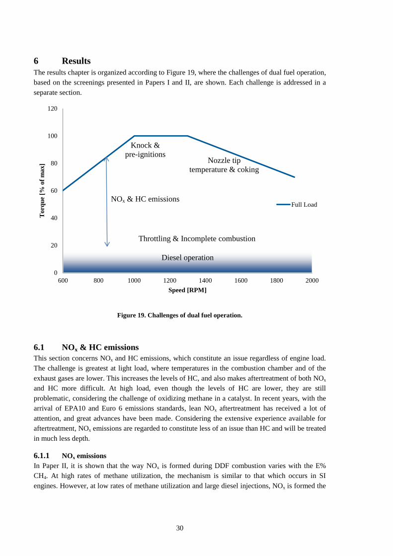
reduction in NOx, as the pilot amount increases, is visible in Figure 20.
Figure 20. NOx and HC emissions versus λ for three different diesel substitution rates.
At high E% CH4, as λ increases, the temperature drops and NOx emissions decrease quickly. NOx
emissions for the 70% CH4 case remain relatively flat as λ changes. The reason for this is that NOx
formation during diesel combustion occurs in regions close to stoichiometry, in the edge of the
flame plume, this mechanism is therefore less sensitive to variations in global λ. It is seen that the
crossover occurs at approximately λ = 1.6. Below this λ, the SI mechanism dominates the NOx
production, while above this λ the diesel mechanism is most influential. If low λ operation is
necessary, for instance during transients, then the diesel amount should be increased slightly to
avoid the peak in NOx production at λ = 1.2. For an extended discussion on NOx formation during
dual fuel combustion, refer to Paper II.
6.1.2 HC emissions
HC emissions are problematic throughout the engine operating range. This is also seen in Figure 20,
where the HC emissions are shown as a function of λ and E% CH4. Also included in the figure, is a
hypothetical limit of 4 g/kWh for engine-out HC emissions. This limit is based on a legislated limit
32
of 0.5 g/kWh for tailpipe emissions, and a conversion efficiency of 90% for a commercial oxidation
catalyst [62]. In order to stay below the limit of 4 g/kWh, the option is to either run at relatively low
λ, or to reduce the diesel substitution rate; neither of which is desirable from an economic point of
view. For this reason, an investigation into the root causes of these emissions was carried out. The
objective was to determine the main sources, their relative importance and how said importance
changes with operating conditions. The full investigation is found in Paper IV. From literature it is
known that combustion chamber crevices, mainly the topland volume, contribute significantly to the
HC emissions. How large this contribution is, has been investigated for stoichiometric SI engines
[41], [63], [64]. However, for lean operation with methane fuel, no studies were found. The effect
of parameter variations has also received insufficient attention.
In order to provoke a response and investigate the sensitivity of HC emissions to the volume of the
topland crevice, a set of pistons with known increases in topland volume were manufactured. The
piston modifications are detailed in chapter 5, Experimental setup.
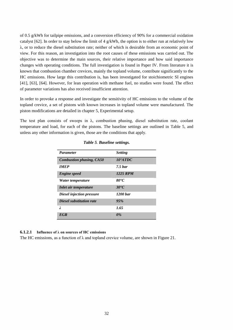
The test plan consists of sweeps in λ, combustion phasing, diesel substitution rate, coolant
temperature and load, for each of the pistons. The baseline settings are outlined in Table 5, and
unless any other information is given, those are the conditions that apply.
Table 5. Baseline settings.
Parameter Setting
Combustion phasing, CA50 10°ATDC
IMEP 7.5 bar
Engine speed 1225 RPM
Water temperature 80°C
Inlet air temperature 30°C
Diesel injection pressure 1200 bar
Diesel substitution rate 95%
λ 1.65
EGR 0%
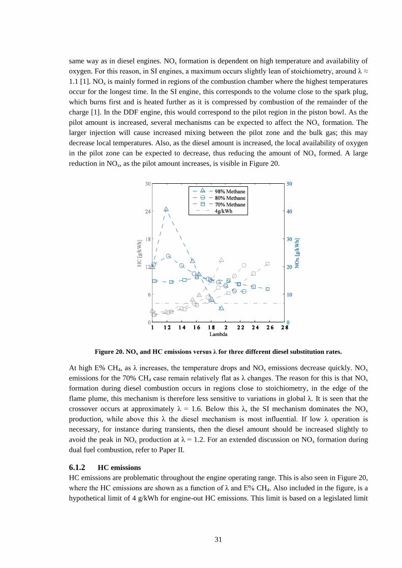
6.1.2.1 Influence of λ on sources of HC emissions
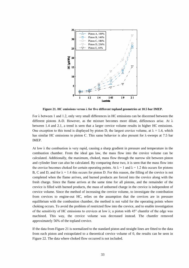
The HC emissions, as a function of λ and topland crevice volume, are shown in Figure 21.
33
Figure 21. HC emissions versus λ for five different topland geometries at 10.5 bar IMEP.
For λ between 1 and 1.2, only very small differences in HC emissions can be discerned between the
different pistons A-D. However, as the mixture becomes more dilute, differences arise. At λ
between 1.4 and 2.1, a trend is seen that a larger crevice volume results in higher HC emissions.
One exception to this trend is displayed by piston D, the largest crevice volume, at λ = 1.4, which
has similar HC emissions to piston C. This same behavior is also present for λ-sweeps at 7.5 bar
IMEP.
At low λ the combustion is very rapid, causing a sharp gradient in pressure and temperature in the
combustion chamber. From the ideal gas law, the mass flow into the crevice volume can be
calculated. Additionally, the maximum, choked, mass flow through the narrow slit between piston
and cylinder liner can also be calculated. By comparing these two, it is seen that the mass flow into
the crevice becomes choked for certain operating points. At λ = 1 and λ = 1.2 this occurs for pistons
B, C and D, and for λ = 1.4 this occurs for piston D. For this reason, the filling of the crevice is not
completed when the flame arrives, and burned products are forced into the crevice along with the
fresh charge. Since the flame arrives at the same time for all pistons, and the remainder of the
crevice is filled with burned products, the mass of unburned charge in the crevice is independent of
crevice volume. Since the method of increasing the crevice volume, to investigate the contribution
from crevices to engine-out HC, relies on the assumption that the crevices are in pressure
equilibrium with the combustion chamber, the method is not valid for the operating points where
choking occurs. To avoid the problem of restricted flow into the crevice, and to enable investigation
of the sensitivity of HC emissions to crevices at low λ; a piston with 45° chamfer of the edge was
machined. This way, the crevice volume was decreased instead. The chamfer removed
approximately 56% of the topland crevice.
If the data from Figure 21 is normalized to the standard piston and straight lines are fitted to the data
from each piston and extrapolated to a theoretical crevice volume of 0, the results can be seen in
Figure 22. The data where choked flow occurred is not included.
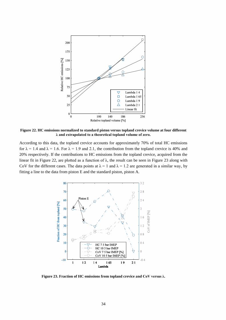
34
Figure 22. HC emissions normalized to standard piston versus topland crevice volume at four different
λ and extrapolated to a theoretical topland volume of zero.
According to this data, the topland crevice accounts for approximately 70% of total HC emissions
for λ = 1.4 and λ = 1.6. For λ = 1.9 and 2.1, the contribution from the topland crevice is 40% and
20% respectively. If the contributions to HC emissions from the topland crevice, acquired from the
linear fit in Figure 22, are plotted as a function of λ, the result can be seen in Figure 23 along with
CoV for the different cases. The data points at λ = 1 and λ = 1.2 are generated in a similar way, by
fitting a line to the data from piston E and the standard piston, piston A.
Figure 23. Fraction of HC emissions from topland crevice and CoV versus λ.
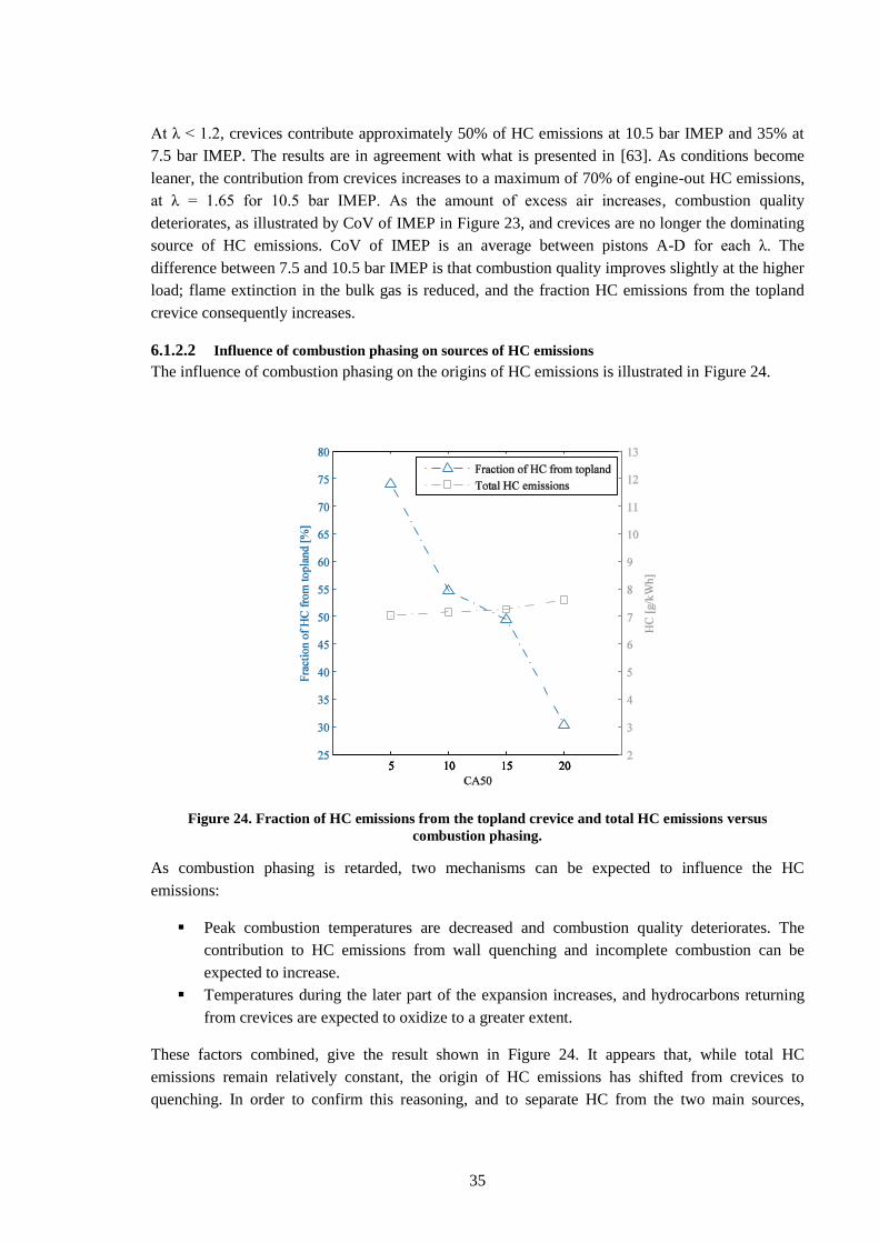
35
At λ < 1.2, crevices contribute approximately 50% of HC emissions at 10.5 bar IMEP and 35% at
7.5 bar IMEP. The results are in agreement with what is presented in [63]. As conditions become
leaner, the contribution from crevices increases to a maximum of 70% of engine-out HC emissions,
at λ = 1.65 for 10.5 bar IMEP. As the amount of excess air increases, combustion quality
deteriorates, as illustrated by CoV of IMEP in Figure 23, and crevices are no longer the dominating
source of HC emissions. CoV of IMEP is an average between pistons A-D for each λ. The
difference between 7.5 and 10.5 bar IMEP is that combustion quality improves slightly at the higher
load; flame extinction in the bulk gas is reduced, and the fraction HC emissions from the topland
crevice consequently increases.
6.1.2.2 Influence of combustion phasing on sources of HC emissions
The influence of combustion phasing on the origins of HC emissions is illustrated in Figure 24.
Figure 24. Fraction of HC emissions from the topland crevice and total HC emissions versus
combustion phasing.
As combustion phasing is retarded, two mechanisms can be expected to influence the HC
emissions:
Peak combustion temperatures are decreased and combustion quality deteriorates. The
contribution to HC emissions from wall quenching and incomplete combustion can be
expected to increase.
Temperatures during the later part of the expansion increases, and hydrocarbons returning
from crevices are expected to oxidize to a greater extent.
These factors combined, give the result shown in Figure 24. It appears that, while total HC
emissions remain relatively constant, the origin of HC emissions has shifted from crevices to
quenching. In order to confirm this reasoning, and to separate HC from the two main sources,
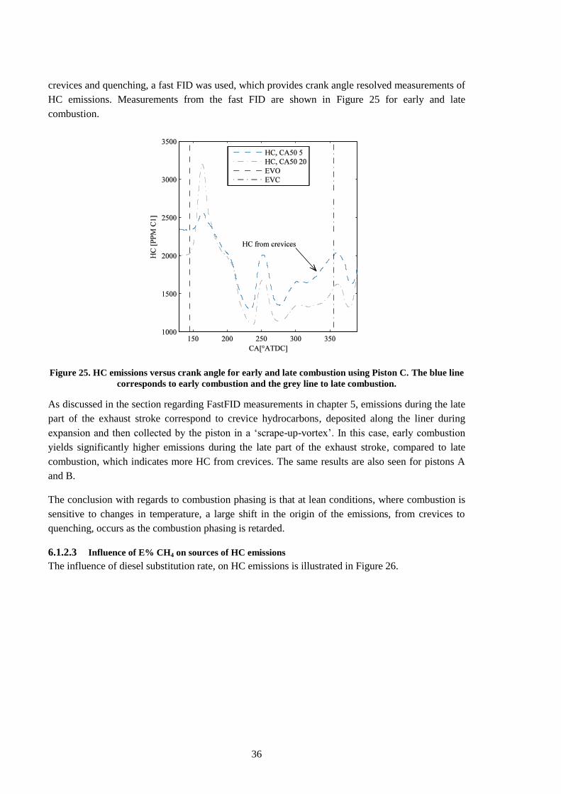
36
crevices and quenching, a fast FID was used, which provides crank angle resolved measurements of
HC emissions. Measurements from the fast FID are shown in Figure 25 for early and late
combustion.
Figure 25. HC emissions versus crank angle for early and late combustion using Piston C. The blue line
corresponds to early combustion and the grey line to late combustion.
As discussed in the section regarding FastFID measurements in chapter 5, emissions during the late
part of the exhaust stroke correspond to crevice hydrocarbons, deposited along the liner during
expansion and then collected by the piston in a „scrape-up-vortex‟. In this case, early combustion
yields significantly higher emissions during the late part of the exhaust stroke, compared to late
combustion, which indicates more HC from crevices. The same results are also seen for pistons A
and B.
The conclusion with regards to combustion phasing is that at lean conditions, where combustion is
sensitive to changes in temperature, a large shift in the origin of the emissions, from crevices to
quenching, occurs as the combustion phasing is retarded.
6.1.2.3 Influence of E% CH4 on sources of HC emissions
The influence of diesel substitution rate, on HC emissions is illustrated in Figure 26.
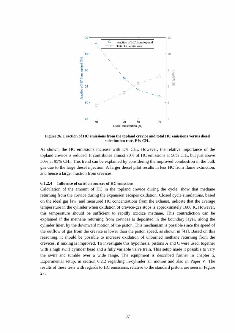
37
Figure 26. Fraction of HC emissions from the topland crevice and total HC emissions versus diesel
substitution rate, E% CH4.
As shown, the HC emissions increase with E% CH4. However, the relative importance of the
topland crevice is reduced. It contributes almost 70% of HC emissions at 50% CH4, but just above
50% at 95% CH4. This trend can be explained by considering the improved combustion in the bulk
gas due to the large diesel injection. A larger diesel pilot results in less HC from flame extinction,
and hence a larger fraction from crevices.
6.1.2.4 Influence of swirl on sources of HC emissions
Calculation of the amount of HC in the topland crevice during the cycle, show that methane
returning from the crevice during the expansion escapes oxidation. Closed cycle simulations, based
on the ideal gas law, and measured HC concentrations from the exhaust, indicate that the average
temperature in the cylinder when oxidation of crevice-gas stops is approximately 1600 K. However,
this temperature should be sufficient to rapidly oxidize methane. This contradiction can be
explained if the methane returning from crevices is deposited in the boundary layer, along the
cylinder liner, by the downward motion of the piston. This mechanism is possible since the speed of
the outflow of gas from the crevice is lower than the piston speed, as shown in [41]. Based on this
reasoning, it should be possible to increase oxidation of unburned methane returning from the
crevices, if mixing is improved. To investigate this hypothesis, pistons A and C were used, together
with a high swirl cylinder head and a fully variable valve train. This setup made it possible to vary
the swirl and tumble over a wide range. The equipment is described further in chapter 5,
Experimental setup, in section 6.2.2 regarding in-cylinder air motion and also in Paper V. The
results of these tests with regards to HC emissions, relative to the standard piston, are seen in Figure
27.
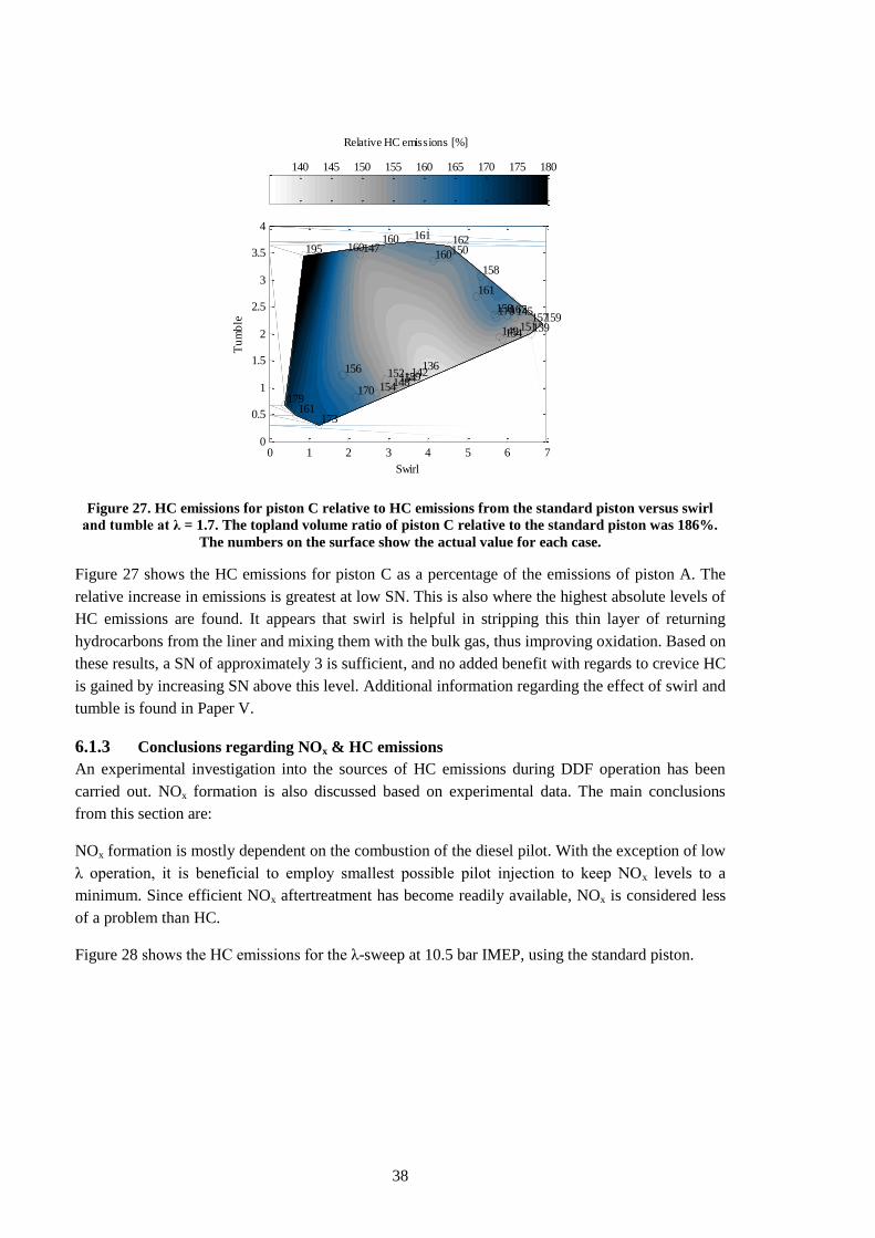
38
Figure 27. HC emissions for piston C relative to HC emissions from the standard piston versus swirl
and tumble at λ = 1.7. The topland volume ratio of piston C relative to the standard piston was 186%.
The numbers on the surface show the actual value for each case.
Figure 27 shows the HC emissions for piston C as a percentage of the emissions of piston A. The
relative increase in emissions is greatest at low SN. This is also where the highest absolute levels of
HC emissions are found. It appears that swirl is helpful in stripping this thin layer of returning
hydrocarbons from the liner and mixing them with the bulk gas, thus improving oxidation. Based on
these results, a SN of approximately 3 is sufficient, and no added benefit with regards to crevice HC
is gained by increasing SN above this level. Additional information regarding the effect of swirl and
tumble is found in Paper V.
6.1.3 Conclusions regarding NOx & HC emissions
An experimental investigation into the sources of HC emissions during DDF operation has been
carried out. NOx formation is also discussed based on experimental data. The main conclusions
from this section are:
NOx formation is mostly dependent on the combustion of the diesel pilot. With the exception of low
λ operation, it is beneficial to employ smallest possible pilot injection to keep NOx levels to a
minimum. Since efficient NOx aftertreatment has become readily available, NOx is considered less
of a problem than HC.
Figure 28 shows the HC emissions for the λ-sweep at 10.5 bar IMEP, using the standard piston.
159148154170
173
179
167158
161
150
161160
145170
160
160195
136142
154152156
161
151149
158
162147
157159139
154
Swirl
Tu
mb
le
0 1 2 3 4 5 6 70
0.5
1
1.5
2
2.5
3
3.5
4
Relative HC emissions [%]
140 145 150 155 160 165 170 175 180
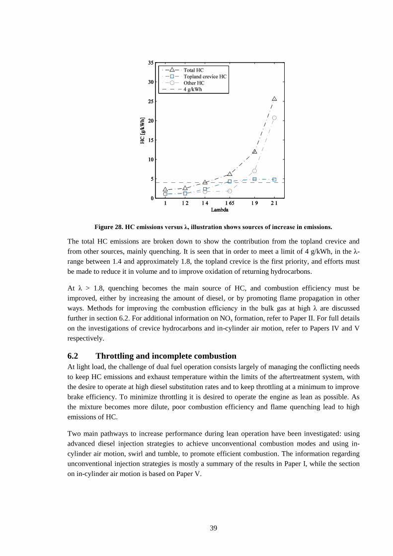
39
Figure 28. HC emissions versus λ, illustration shows sources of increase in emissions.
The total HC emissions are broken down to show the contribution from the topland crevice and
from other sources, mainly quenching. It is seen that in order to meet a limit of 4 g/kWh, in the λ-
range between 1.4 and approximately 1.8, the topland crevice is the first priority, and efforts must
be made to reduce it in volume and to improve oxidation of returning hydrocarbons.
At λ > 1.8, quenching becomes the main source of HC, and combustion efficiency must be
improved, either by increasing the amount of diesel, or by promoting flame propagation in other
ways. Methods for improving the combustion efficiency in the bulk gas at high λ are discussed
further in section 6.2. For additional information on NOx formation, refer to Paper II. For full details
on the investigations of crevice hydrocarbons and in-cylinder air motion, refer to Papers IV and V
respectively.
6.2 Throttling and incomplete combustion
At light load, the challenge of dual fuel operation consists largely of managing the conflicting needs
to keep HC emissions and exhaust temperature within the limits of the aftertreatment system, with
the desire to operate at high diesel substitution rates and to keep throttling at a minimum to improve
brake efficiency. To minimize throttling it is desired to operate the engine as lean as possible. As
the mixture becomes more dilute, poor combustion efficiency and flame quenching lead to high
emissions of HC.
Two main pathways to increase performance during lean operation have been investigated: using
advanced diesel injection strategies to achieve unconventional combustion modes and using in-
cylinder air motion, swirl and tumble, to promote efficient combustion. The information regarding
unconventional injection strategies is mostly a summary of the results in Paper I, while the section
on in-cylinder air motion is based on Paper V.
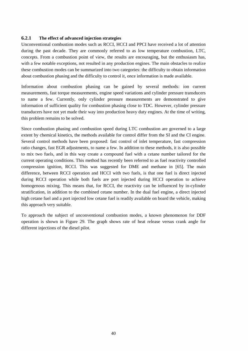
40
6.2.1 The effect of advanced injection strategies
Unconventional combustion modes such as RCCI, HCCI and PPCI have received a lot of attention
during the past decade. They are commonly referred to as low temperature combustion, LTC,
concepts. From a combustion point of view, the results are encouraging, but the enthusiasm has,
with a few notable exceptions, not resulted in any production engines. The main obstacles to realize
these combustion modes can be summarized into two categories: the difficulty to obtain information
about combustion phasing and the difficulty to control it, once information is made available.
Information about combustion phasing can be gained by several methods: ion current
measurements, fast torque measurements, engine speed variations and cylinder pressure transducers
to name a few. Currently, only cylinder pressure measurements are demonstrated to give
information of sufficient quality for combustion phasing close to TDC. However, cylinder pressure
transducers have not yet made their way into production heavy duty engines. At the time of writing,
this problem remains to be solved.
Since combustion phasing and combustion speed during LTC combustion are governed to a large
extent by chemical kinetics, the methods available for control differ from the SI and the CI engine.
Several control methods have been proposed: fast control of inlet temperature, fast compression
ratio changes, fast EGR adjustments, to name a few. In addition to these methods, it is also possible
to mix two fuels, and in this way create a compound fuel with a cetane number tailored for the
current operating conditions. This method has recently been referred to as fuel reactivity controlled
compression ignition, RCCI. This was suggested for DME and methane in [65]. The main
difference, between RCCI operation and HCCI with two fuels, is that one fuel is direct injected
during RCCI operation while both fuels are port injected during HCCI operation to achieve
homogenous mixing. This means that, for RCCI, the reactivity can be influenced by in-cylinder
stratification, in addition to the combined cetane number. In the dual fuel engine, a direct injected
high cetane fuel and a port injected low cetane fuel is readily available on board the vehicle, making
this approach very suitable.
To approach the subject of unconventional combustion modes, a known phenomenon for DDF
operation is shown in Figure 29. The graph shows rate of heat release versus crank angle for
different injections of the diesel pilot.
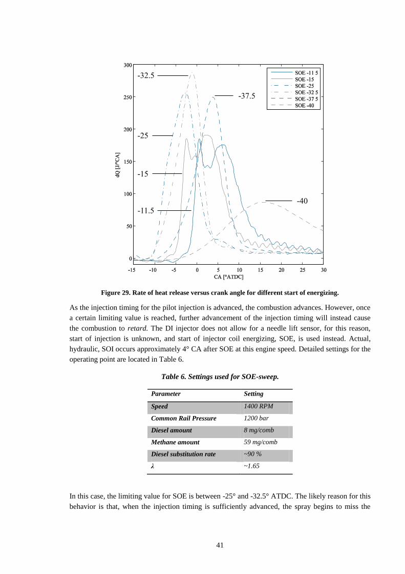
41
Figure 29. Rate of heat release versus crank angle for different start of energizing.
As the injection timing for the pilot injection is advanced, the combustion advances. However, once
a certain limiting value is reached, further advancement of the injection timing will instead cause
the combustion to retard. The DI injector does not allow for a needle lift sensor, for this reason,
start of injection is unknown, and start of injector coil energizing, SOE, is used instead. Actual,
hydraulic, SOI occurs approximately 4° CA after SOE at this engine speed. Detailed settings for the
operating point are located in Table 6.
Table 6. Settings used for SOE-sweep.
Parameter Setting
Speed 1400 RPM
Common Rail Pressure 1200 bar
Diesel amount 8 mg/comb
Methane amount 59 mg/comb
Diesel substitution rate ~90 %
λ ~1.65
In this case, the limiting value for SOE is between -25° and -32.5° ATDC. The likely reason for this
behavior is that, when the injection timing is sufficiently advanced, the spray begins to miss the
-25
-37.5
-11.5
-15
-40
-32.5
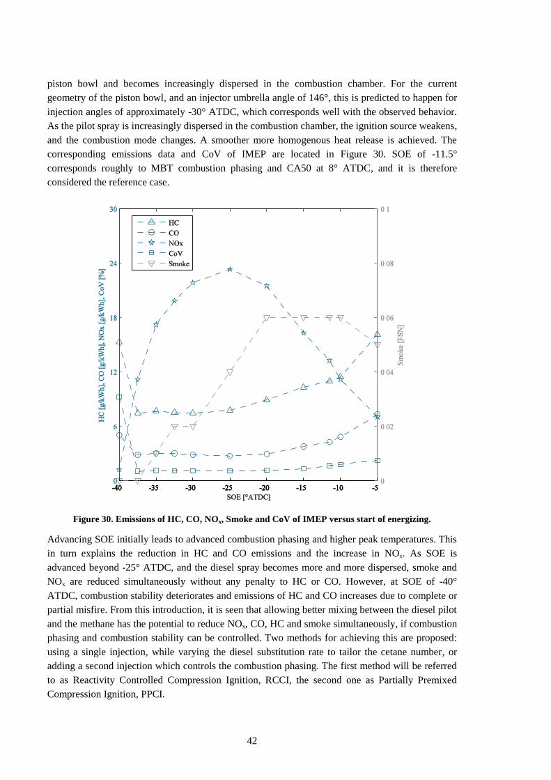
42
piston bowl and becomes increasingly dispersed in the combustion chamber. For the current
geometry of the piston bowl, and an injector umbrella angle of 146°, this is predicted to happen for
injection angles of approximately -30° ATDC, which corresponds well with the observed behavior.
As the pilot spray is increasingly dispersed in the combustion chamber, the ignition source weakens,
and the combustion mode changes. A smoother more homogenous heat release is achieved. The
corresponding emissions data and CoV of IMEP are located in Figure 30. SOE of -11.5°
corresponds roughly to MBT combustion phasing and CA50 at 8° ATDC, and it is therefore
considered the reference case.
Figure 30. Emissions of HC, CO, NOx, Smoke and CoV of IMEP versus start of energizing.
Advancing SOE initially leads to advanced combustion phasing and higher peak temperatures. This
in turn explains the reduction in HC and CO emissions and the increase in NOx. As SOE is
advanced beyond -25° ATDC, and the diesel spray becomes more and more dispersed, smoke and
NOx are reduced simultaneously without any penalty to HC or CO. However, at SOE of -40°
ATDC, combustion stability deteriorates and emissions of HC and CO increases due to complete or
partial misfire. From this introduction, it is seen that allowing better mixing between the diesel pilot
and the methane has the potential to reduce NOx, CO, HC and smoke simultaneously, if combustion
phasing and combustion stability can be controlled. Two methods for achieving this are proposed:
using a single injection, while varying the diesel substitution rate to tailor the cetane number, or
adding a second injection which controls the combustion phasing. The first method will be referred
to as Reactivity Controlled Compression Ignition, RCCI, the second one as Partially Premixed
Compression Ignition, PPCI.
43
6.2.1.1 RCCI/HCCI
As the injection timing in Figure 30 is advanced to -40° ATDC, near zero emissions of NOx and
smoke are achieved, but HC and CO emissions deteriorate along with combustion stability. This can
be addressed by increasing the size of the diesel injection and advancing it even further, to allow
longer time for mixing. This results in RCCI combustion with low HC and CO emissions,
satisfactory combustion stability and near zero emissions of NOx and smoke.
In RCCI combustion, the combustion timing and speed are governed mainly by chemical kinetics
and to some extent by in-cylinder stratification of the direct injected fuel. Combustion is therefore
very sensitive to the small changes in local temperature, which occur stochastically in combustion
engines. There is also a strong possibility of positive feedback; if combustion occurs early one
cycle, more heat is transferred to the combustion chamber walls, thus heating valves and piston
crown. Because of this, the gases during the next cycle are exposed to higher temperatures, and the
probability increases that combustion will advance even further. This situation can quickly escalate
and, within fractions of a second, lead to intolerable peak firing pressures and rates of pressure rise.
This behavior is aggravated as the load increases, and it is highly unlikely that RCCI combustion
can be controlled without closed loop cylinder pressure feedback.
In the DDF engine, RCCI combustion phasing is controlled by varying the ratio between the high
cetane fuel, diesel, and the low cetane fuel, methane. More diesel for a given load advances the
combustion phasing and more methane delays combustion. Rate of heat release for 4 cycles of
RCCI combustion using methane-diesel dual fuelling is shown in Figure 31.
Figure 31. Rate of heat release versus crank angle for RCCI combustion, 6.5 bar BMEP, 1400 RPM
and 70% methane.
At around -20° ATDC some cool flame activity can be observed. Depending on pressure and
temperature of the operating point, the main heat release may be preceded by cool flame oxidation
of parts of the diesel fuel. During this phase, radicals and CO are formed which accelerate the main
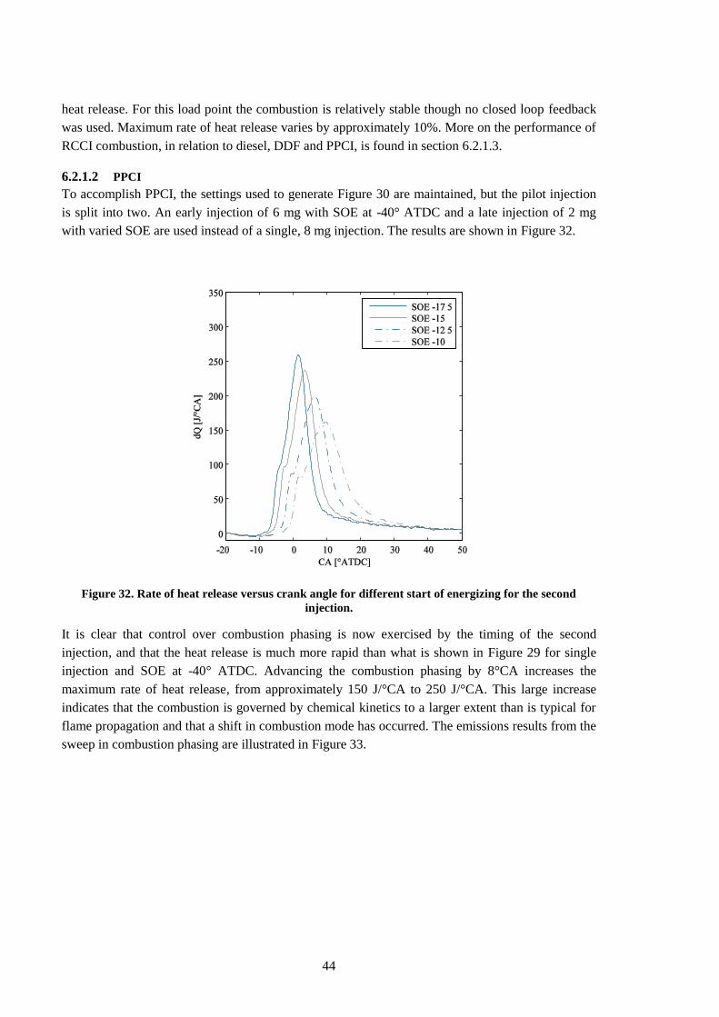
44
heat release. For this load point the combustion is relatively stable though no closed loop feedback
was used. Maximum rate of heat release varies by approximately 10%. More on the performance of
RCCI combustion, in relation to diesel, DDF and PPCI, is found in section 6.2.1.3.
6.2.1.2 PPCI
To accomplish PPCI, the settings used to generate Figure 30 are maintained, but the pilot injection
is split into two. An early injection of 6 mg with SOE at -40° ATDC and a late injection of 2 mg
with varied SOE are used instead of a single, 8 mg injection. The results are shown in Figure 32.
Figure 32. Rate of heat release versus crank angle for different start of energizing for the second
injection.
It is clear that control over combustion phasing is now exercised by the timing of the second
injection, and that the heat release is much more rapid than what is shown in Figure 29 for single
injection and SOE at -40° ATDC. Advancing the combustion phasing by 8°CA increases the
maximum rate of heat release, from approximately 150 J/°CA to 250 J/°CA. This large increase
indicates that the combustion is governed by chemical kinetics to a larger extent than is typical for
flame propagation and that a shift in combustion mode has occurred. The emissions results from the
sweep in combustion phasing are illustrated in Figure 33.
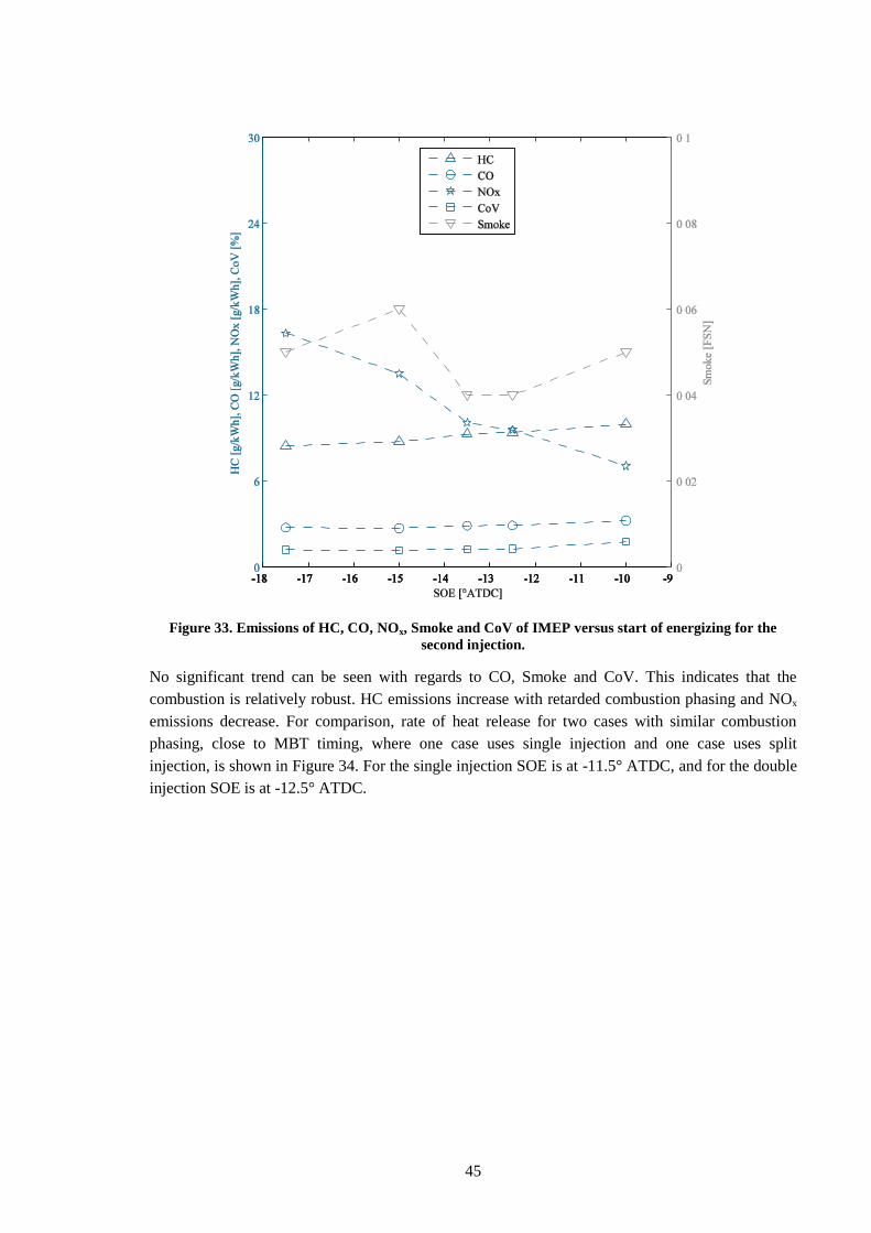
45
Figure 33. Emissions of HC, CO, NOx, Smoke and CoV of IMEP versus start of energizing for the
second injection.
No significant trend can be seen with regards to CO, Smoke and CoV. This indicates that the
combustion is relatively robust. HC emissions increase with retarded combustion phasing and NOx
emissions decrease. For comparison, rate of heat release for two cases with similar combustion
phasing, close to MBT timing, where one case uses single injection and one case uses split
injection, is shown in Figure 34. For the single injection SOE is at -11.5° ATDC, and for the double
injection SOE is at -12.5° ATDC.
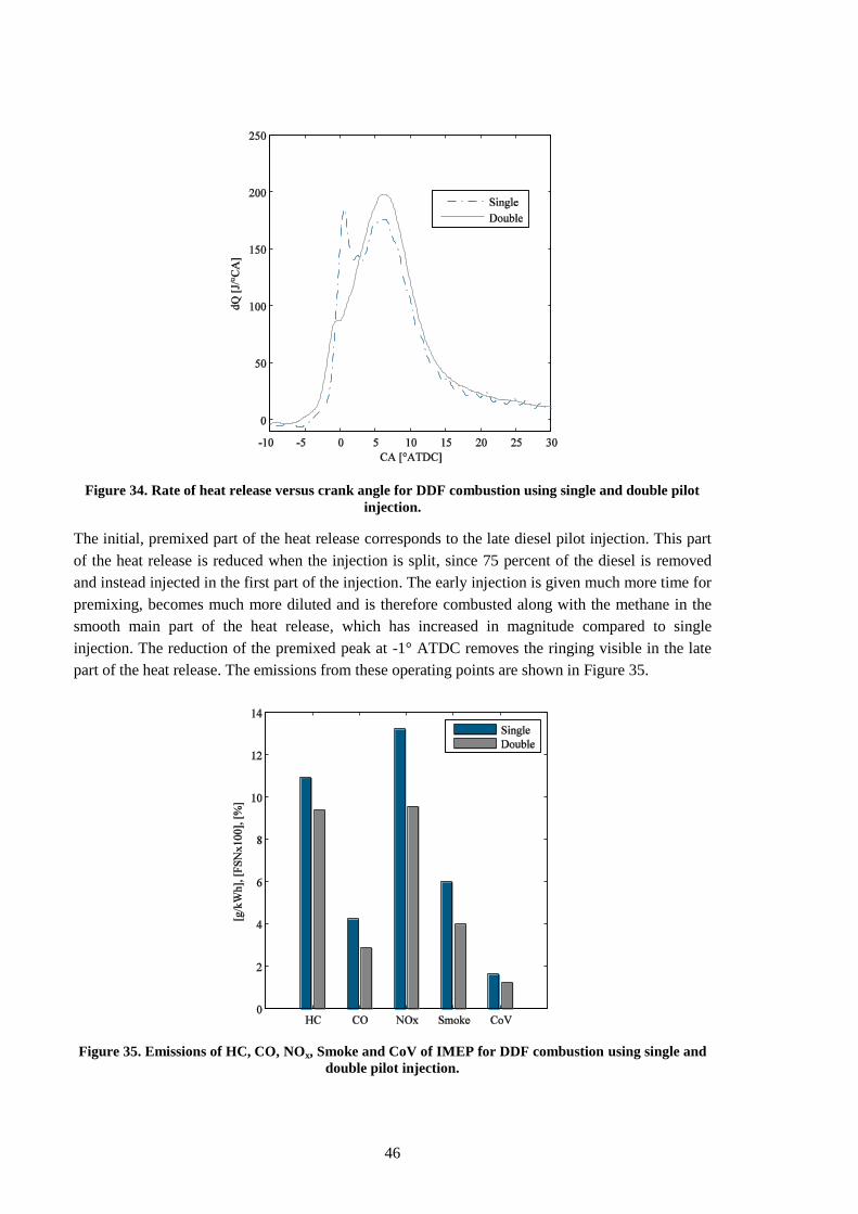
46
Figure 34. Rate of heat release versus crank angle for DDF combustion using single and double pilot
injection.
The initial, premixed part of the heat release corresponds to the late diesel pilot injection. This part
of the heat release is reduced when the injection is split, since 75 percent of the diesel is removed
and instead injected in the first part of the injection. The early injection is given much more time for
premixing, becomes much more diluted and is therefore combusted along with the methane in the
smooth main part of the heat release, which has increased in magnitude compared to single
injection. The reduction of the premixed peak at -1° ATDC removes the ringing visible in the late
part of the heat release. The emissions from these operating points are shown in Figure 35.
Figure 35. Emissions of HC, CO, NOx, Smoke and CoV of IMEP for DDF combustion using single and
double pilot injection.
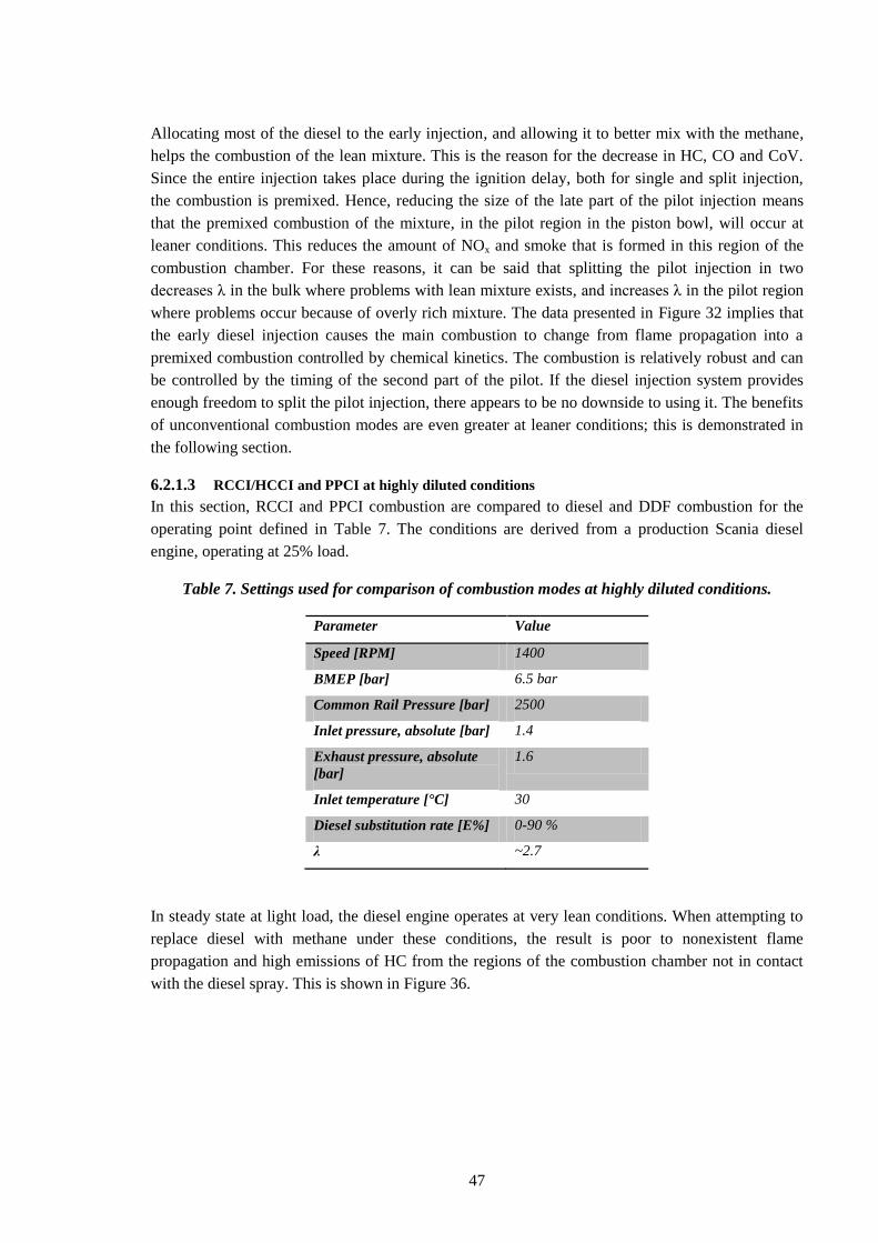
47
Allocating most of the diesel to the early injection, and allowing it to better mix with the methane,
helps the combustion of the lean mixture. This is the reason for the decrease in HC, CO and CoV.
Since the entire injection takes place during the ignition delay, both for single and split injection,
the combustion is premixed. Hence, reducing the size of the late part of the pilot injection means
that the premixed combustion of the mixture, in the pilot region in the piston bowl, will occur at
leaner conditions. This reduces the amount of NOx and smoke that is formed in this region of the
combustion chamber. For these reasons, it can be said that splitting the pilot injection in two
decreases λ in the bulk where problems with lean mixture exists, and increases λ in the pilot region
where problems occur because of overly rich mixture. The data presented in Figure 32 implies that
the early diesel injection causes the main combustion to change from flame propagation into a
premixed combustion controlled by chemical kinetics. The combustion is relatively robust and can
be controlled by the timing of the second part of the pilot. If the diesel injection system provides
enough freedom to split the pilot injection, there appears to be no downside to using it. The benefits
of unconventional combustion modes are even greater at leaner conditions; this is demonstrated in
the following section.
6.2.1.3 RCCI/HCCI and PPCI at highly diluted conditions
In this section, RCCI and PPCI combustion are compared to diesel and DDF combustion for the
operating point defined in Table 7. The conditions are derived from a production Scania diesel
engine, operating at 25% load.
Table 7. Settings used for comparison of combustion modes at highly diluted conditions.
Parameter Value
Speed [RPM] 1400
BMEP [bar] 6.5 bar
Common Rail Pressure [bar] 2500
Inlet pressure, absolute [bar] 1.4
Exhaust pressure, absolute
[bar]
1.6
Inlet temperature [°C] 30
Diesel substitution rate [E%] 0-90 %
λ ~2.7
In steady state at light load, the diesel engine operates at very lean conditions. When attempting to
replace diesel with methane under these conditions, the result is poor to nonexistent flame
propagation and high emissions of HC from the regions of the combustion chamber not in contact
with the diesel spray. This is shown in Figure 36.
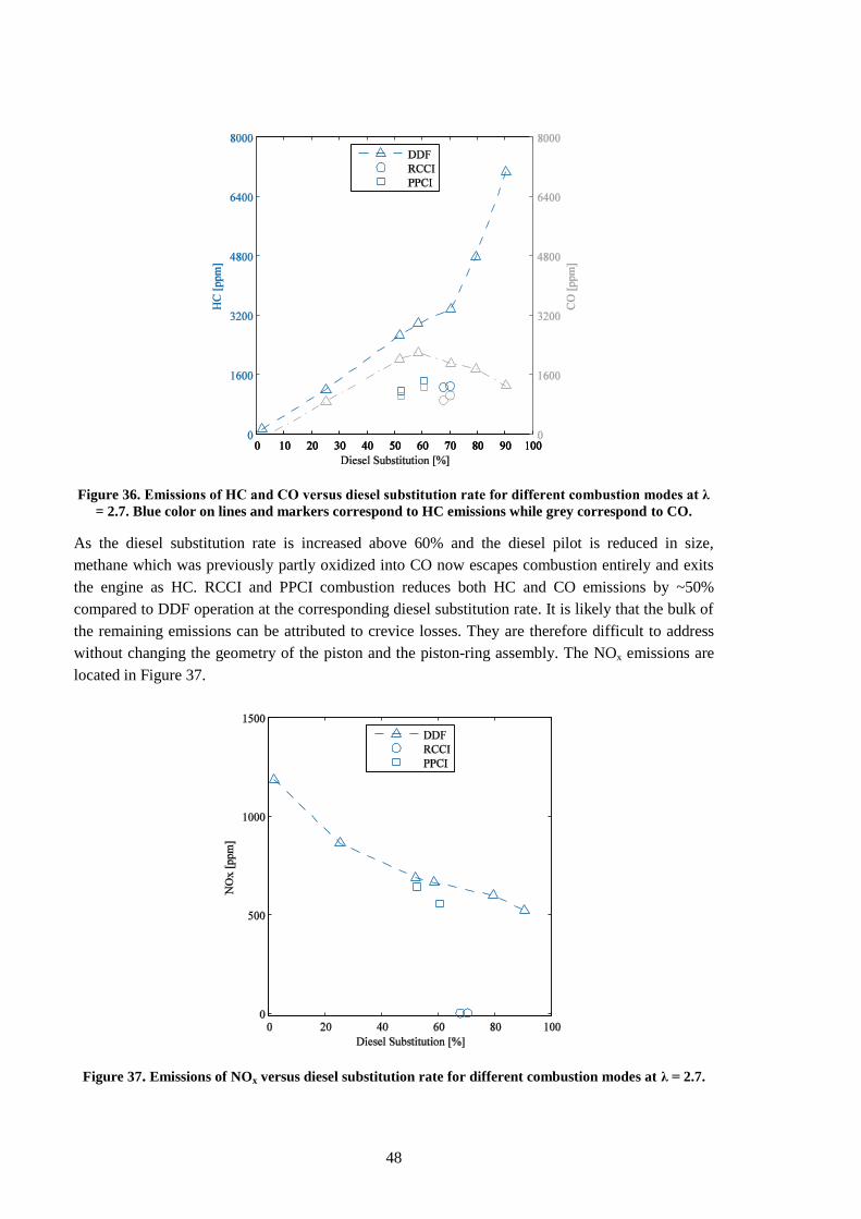
48
Figure 36. Emissions of HC and CO versus diesel substitution rate for different combustion modes at λ
= 2.7. Blue color on lines and markers correspond to HC emissions while grey correspond to CO.
As the diesel substitution rate is increased above 60% and the diesel pilot is reduced in size,
methane which was previously partly oxidized into CO now escapes combustion entirely and exits
the engine as HC. RCCI and PPCI combustion reduces both HC and CO emissions by ~50%
compared to DDF operation at the corresponding diesel substitution rate. It is likely that the bulk of
the remaining emissions can be attributed to crevice losses. They are therefore difficult to address
without changing the geometry of the piston and the piston-ring assembly. The NOx emissions are
located in Figure 37.
Figure 37. Emissions of NOx versus diesel substitution rate for different combustion modes at λ = 2.7.
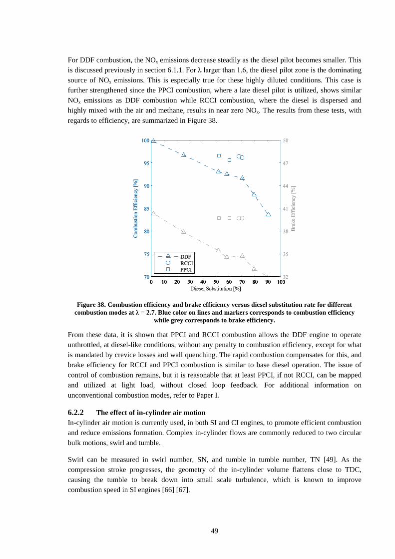
49
For DDF combustion, the NOx emissions decrease steadily as the diesel pilot becomes smaller. This
is discussed previously in section 6.1.1. For λ larger than 1.6, the diesel pilot zone is the dominating
source of NOx emissions. This is especially true for these highly diluted conditions. This case is
further strengthened since the PPCI combustion, where a late diesel pilot is utilized, shows similar
NOx emissions as DDF combustion while RCCI combustion, where the diesel is dispersed and
highly mixed with the air and methane, results in near zero NOx. The results from these tests, with
regards to efficiency, are summarized in Figure 38.
Figure 38. Combustion efficiency and brake efficiency versus diesel substitution rate for different
combustion modes at λ = 2.7. Blue color on lines and markers corresponds to combustion efficiency
while grey corresponds to brake efficiency.
From these data, it is shown that PPCI and RCCI combustion allows the DDF engine to operate
unthrottled, at diesel-like conditions, without any penalty to combustion efficiency, except for what
is mandated by crevice losses and wall quenching. The rapid combustion compensates for this, and
brake efficiency for RCCI and PPCI combustion is similar to base diesel operation. The issue of
control of combustion remains, but it is reasonable that at least PPCI, if not RCCI, can be mapped
and utilized at light load, without closed loop feedback. For additional information on
unconventional combustion modes, refer to Paper I.
6.2.2 The effect of in-cylinder air motion
In-cylinder air motion is currently used, in both SI and CI engines, to promote efficient combustion
and reduce emissions formation. Complex in-cylinder flows are commonly reduced to two circular
bulk motions, swirl and tumble.
Swirl can be measured in swirl number, SN, and tumble in tumble number, TN [49]. As the
compression stroke progresses, the geometry of the in-cylinder volume flattens close to TDC,
causing the tumble to break down into small scale turbulence, which is known to improve
combustion speed in SI engines [66] [67].
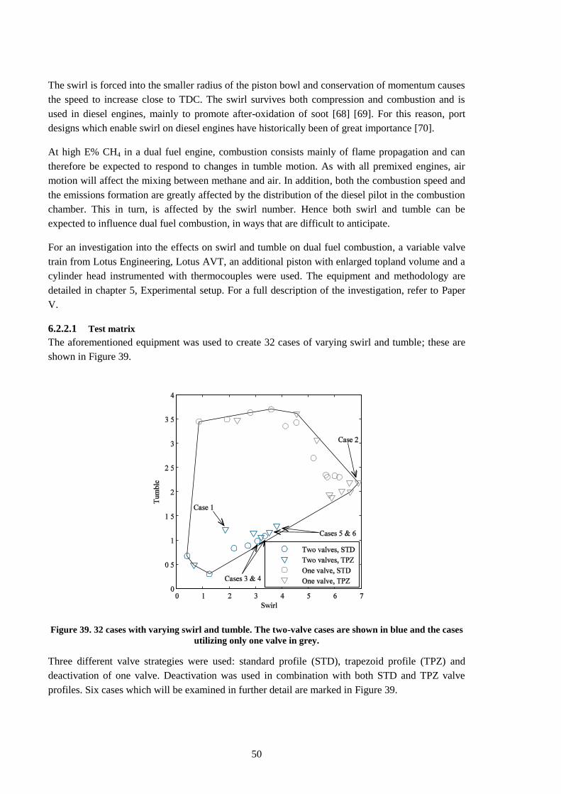
50
The swirl is forced into the smaller radius of the piston bowl and conservation of momentum causes
the speed to increase close to TDC. The swirl survives both compression and combustion and is
used in diesel engines, mainly to promote after-oxidation of soot [68] [69]. For this reason, port
designs which enable swirl on diesel engines have historically been of great importance [70].
At high E% CH4 in a dual fuel engine, combustion consists mainly of flame propagation and can
therefore be expected to respond to changes in tumble motion. As with all premixed engines, air
motion will affect the mixing between methane and air. In addition, both the combustion speed and
the emissions formation are greatly affected by the distribution of the diesel pilot in the combustion
chamber. This in turn, is affected by the swirl number. Hence both swirl and tumble can be
expected to influence dual fuel combustion, in ways that are difficult to anticipate.
For an investigation into the effects on swirl and tumble on dual fuel combustion, a variable valve
train from Lotus Engineering, Lotus AVT, an additional piston with enlarged topland volume and a
cylinder head instrumented with thermocouples were used. The equipment and methodology are
detailed in chapter 5, Experimental setup. For a full description of the investigation, refer to Paper
V.
6.2.2.1 Test matrix
The aforementioned equipment was used to create 32 cases of varying swirl and tumble; these are
shown in Figure 39.
Figure 39. 32 cases with varying swirl and tumble. The two-valve cases are shown in blue and the cases
utilizing only one valve in grey.
Three different valve strategies were used: standard profile (STD), trapezoid profile (TPZ) and
deactivation of one valve. Deactivation was used in combination with both STD and TPZ valve
profiles. Six cases which will be examined in further detail are marked in Figure 39.
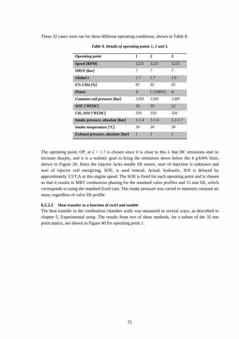
51
These 32 cases were run for three different operating conditions, shown in Table 8.
Table 8. Details of operating points 1, 2 and 3.
Operating point 1 2 3
Speed [RPM] 1225 1225 1225
IMEP [bar] 7 7 7
Global λ 1.7 1.7 1.9
E% CH4 [%] 95 95 95
Piston A C (186%) A
Common rail pressure [bar] 1200 1200 1200
SOE [°BTDC] 10 10 12
CH4 SOI [°BTDC] 350 350 350
Intake pressure, absolute [bar] 1-1.4 1-1.4 1.2-1.7
Intake temperature [°C] 30 30 30
Exhaust pressure, absolute [bar] 1 1 1
The operating point, OP, at λ = 1.7 is chosen since it is close to this λ that HC emissions start to
increase sharply, and it is a realistic goal to bring the emissions down below the 4 g/kWh limit,
shown in Figure 20. Since the injector lacks needle lift sensor, start of injection is unknown and
start of injector coil energizing, SOE, is used instead. Actual, hydraulic, SOI is delayed by
approximately 3.5°CA at this engine speed. The SOE is fixed for each operating point and is chosen
so that it results in MBT combustion phasing for the standard valve profiles and 15 mm lift, which
corresponds to using the standard fixed cam. The intake pressure was varied to maintain constant air
mass, regardless of valve lift profile.
6.2.2.2 Heat transfer as a function of swirl and tumble
The heat transfer to the combustion chamber walls was measured in several ways, as described in
chapter 5, Experimental setup. The results from two of these methods, for a subset of the 32 test
point matrix, are shown in Figure 40 for operating point 1.
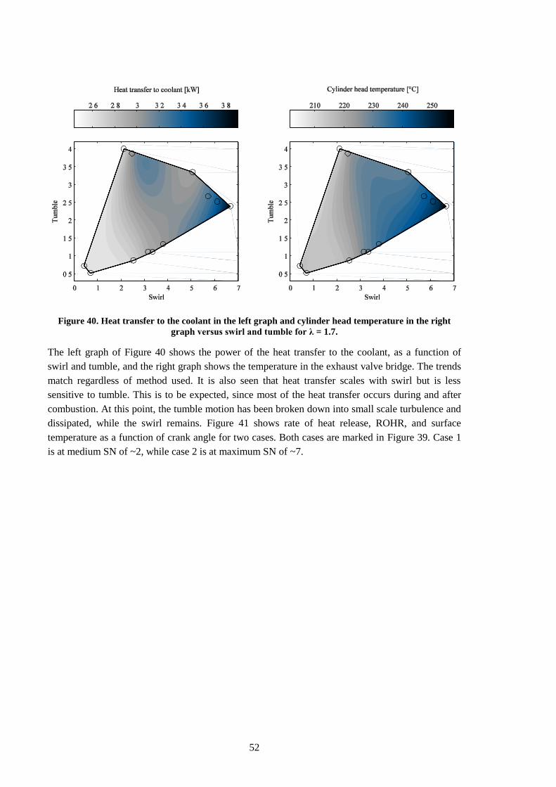
52
Figure 40. Heat transfer to the coolant in the left graph and cylinder head temperature in the right
graph versus swirl and tumble for λ = 1.7.
The left graph of Figure 40 shows the power of the heat transfer to the coolant, as a function of
swirl and tumble, and the right graph shows the temperature in the exhaust valve bridge. The trends
match regardless of method used. It is also seen that heat transfer scales with swirl but is less
sensitive to tumble. This is to be expected, since most of the heat transfer occurs during and after
combustion. At this point, the tumble motion has been broken down into small scale turbulence and
dissipated, while the swirl remains. Figure 41 shows rate of heat release, ROHR, and surface
temperature as a function of crank angle for two cases. Both cases are marked in Figure 39. Case 1
is at medium SN of ~2, while case 2 is at maximum SN of ~7.
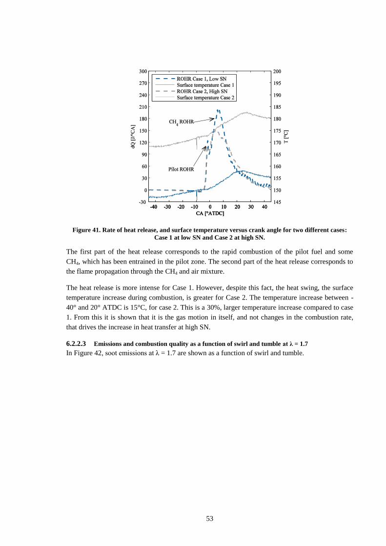
53
Figure 41. Rate of heat release, and surface temperature versus crank angle for two different cases:
Case 1 at low SN and Case 2 at high SN.
The first part of the heat release corresponds to the rapid combustion of the pilot fuel and some
CH4, which has been entrained in the pilot zone. The second part of the heat release corresponds to
the flame propagation through the CH4 and air mixture.
The heat release is more intense for Case 1. However, despite this fact, the heat swing, the surface
temperature increase during combustion, is greater for Case 2. The temperature increase between -
40° and 20° ATDC is 15°C, for case 2. This is a 30%, larger temperature increase compared to case
1. From this it is shown that it is the gas motion in itself, and not changes in the combustion rate,
that drives the increase in heat transfer at high SN.
6.2.2.3 Emissions and combustion quality as a function of swirl and tumble at λ = 1.7
In Figure 42, soot emissions at λ = 1.7 are shown as a function of swirl and tumble.
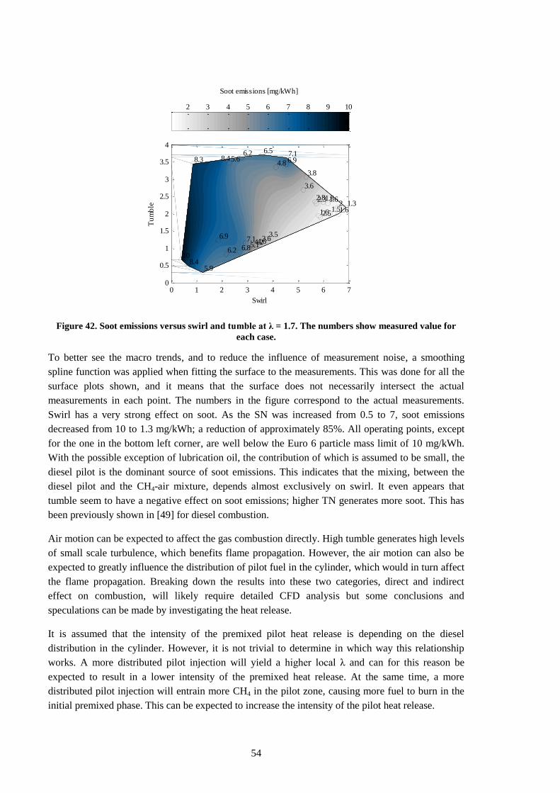
54
Figure 42. Soot emissions versus swirl and tumble at λ = 1.7. The numbers show measured value for
each case.
To better see the macro trends, and to reduce the influence of measurement noise, a smoothing
spline function was applied when fitting the surface to the measurements. This was done for all the
surface plots shown, and it means that the surface does not necessarily intersect the actual
measurements in each point. The numbers in the figure correspond to the actual measurements.
Swirl has a very strong effect on soot. As the SN was increased from 0.5 to 7, soot emissions
decreased from 10 to 1.3 mg/kWh; a reduction of approximately 85%. All operating points, except
for the one in the bottom left corner, are well below the Euro 6 particle mass limit of 10 mg/kWh.
With the possible exception of lubrication oil, the contribution of which is assumed to be small, the
diesel pilot is the dominant source of soot emissions. This indicates that the mixing, between the
diesel pilot and the CH4-air mixture, depends almost exclusively on swirl. It even appears that
tumble seem to have a negative effect on soot emissions; higher TN generates more soot. This has
been previously shown in [49] for diesel combustion.
Air motion can be expected to affect the gas combustion directly. High tumble generates high levels
of small scale turbulence, which benefits flame propagation. However, the air motion can also be
expected to greatly influence the distribution of pilot fuel in the cylinder, which would in turn affect
the flame propagation. Breaking down the results into these two categories, direct and indirect
effect on combustion, will likely require detailed CFD analysis but some conclusions and
speculations can be made by investigating the heat release.
It is assumed that the intensity of the premixed pilot heat release is depending on the diesel
distribution in the cylinder. However, it is not trivial to determine in which way this relationship
works. A more distributed pilot injection will yield a higher local λ and can for this reason be
expected to result in a lower intensity of the premixed heat release. At the same time, a more
distributed pilot injection will entrain more CH4 in the pilot zone, causing more fuel to burn in the
initial premixed phase. This can be expected to increase the intensity of the pilot heat release.
4.6
2.8
8.410
4.8
5.1
3.8
5.6
6.9
2.5
2
7.1
6.5
5.9
1.8
4.2
1.3
3.6
1.6 1.5
2.3
6.26.98.4
6.2
3.6
6.8
3.5
8.3
1.6
1.6
7.1
Swirl
Tu
mb
le
0 1 2 3 4 5 6 70
0.5
1
1.5
2
2.5
3
3.5
4
Soot emissions [mg/kWh]
2 3 4 5 6 7 8 9 10
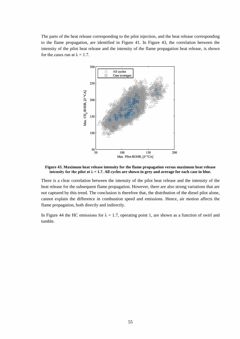
55
The parts of the heat release corresponding to the pilot injection, and the heat release corresponding
to the flame propagation, are identified in Figure 41. In Figure 43, the correlation between the
intensity of the pilot heat release and the intensity of the flame propagation heat release, is shown
for the cases run at λ = 1.7.
Figure 43. Maximum heat release intensity for the flame propagation versus maximum heat release
intensity for the pilot at λ = 1.7. All cycles are shown in grey and average for each case in blue.
There is a clear correlation between the intensity of the pilot heat release and the intensity of the
heat release for the subsequent flame propagation. However, there are also strong variations that are
not captured by this trend. The conclusion is therefore that, the distribution of the diesel pilot alone,
cannot explain the difference in combustion speed and emissions. Hence, air motion affects the
flame propagation, both directly and indirectly.
In Figure 44 the HC emissions for λ = 1.7, operating point 1, are shown as a function of swirl and
tumble.
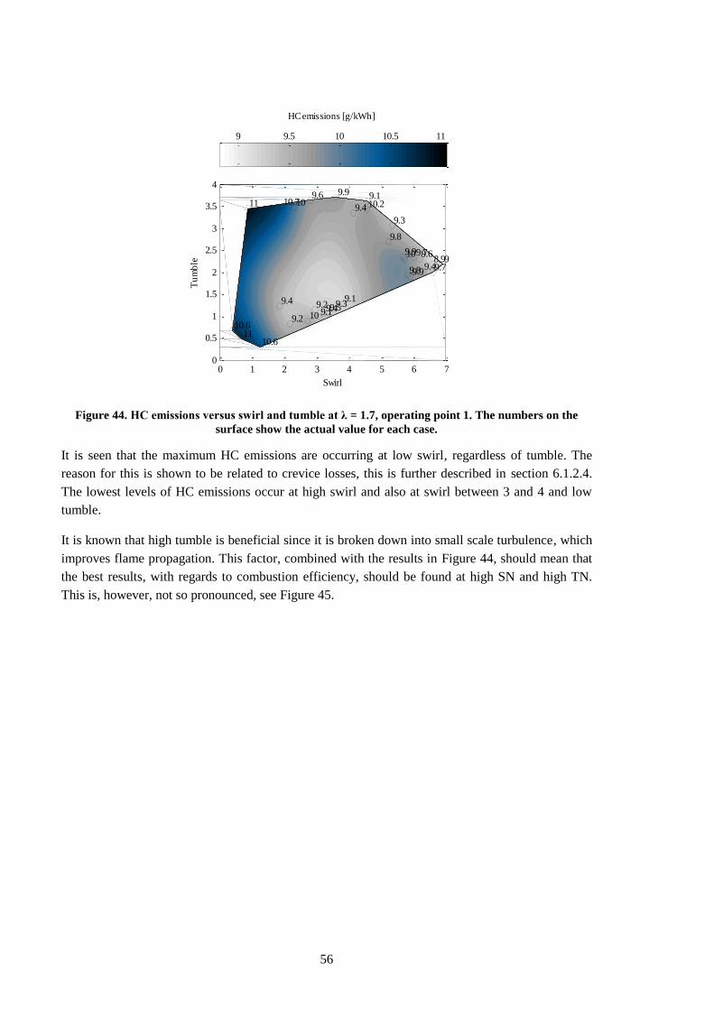
56
Figure 44. HC emissions versus swirl and tumble at λ = 1.7, operating point 1. The numbers on the
surface show the actual value for each case.
It is seen that the maximum HC emissions are occurring at low swirl, regardless of tumble. The
reason for this is shown to be related to crevice losses, this is further described in section 6.1.2.4.
The lowest levels of HC emissions occur at high swirl and also at swirl between 3 and 4 and low
tumble.
It is known that high tumble is beneficial since it is broken down into small scale turbulence, which
improves flame propagation. This factor, combined with the results in Figure 44, should mean that
the best results, with regards to combustion efficiency, should be found at high SN and high TN.
This is, however, not so pronounced, see Figure 45.
9.5
9.9
1110.6
9.4
9.1
9.3
10
9.4
9.9
8.9
9.2
9.9
10.6
9.7
9.4
9
9.8
9.8 9.4
10
9.610.210.7
9.2
9.3
10
9.1
11
9.7
9.6
9.1
Swirl
Tu
mb
le
0 1 2 3 4 5 6 70
0.5
1
1.5
2
2.5
3
3.5
4
HC emissions [g/kWh]
9 9.5 10 10.5 11
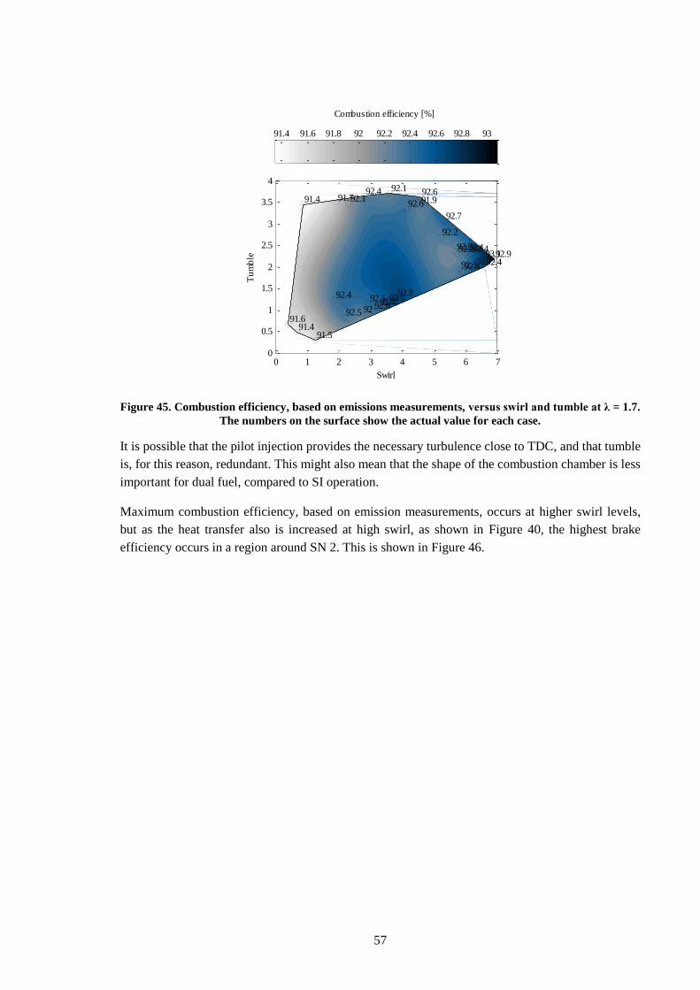
57
Figure 45. Combustion efficiency, based on emissions measurements, versus swirl and tumble at λ = 1.7.
The numbers on the surface show the actual value for each case.
It is possible that the pilot injection provides the necessary turbulence close to TDC, and that tumble
is, for this reason, redundant. This might also mean that the shape of the combustion chamber is less
important for dual fuel, compared to SI operation.
Maximum combustion efficiency, based on emission measurements, occurs at higher swirl levels,
but as the heat transfer also is increased at high swirl, as shown in Figure 40, the highest brake
efficiency occurs in a region around SN 2. This is shown in Figure 46.
92.2
92.2
91.491.6
92.6
92.6
92.7
92.1
92.4
92.4
93.1
92.5
92.1
91.5
92.4
92.4
92.9
92.2
92.392.7
92.2
92.491.991.7
92.5
92.5
92
92.9
91.4
92.4
92.4
92.6
Swirl
Tu
mb
le
0 1 2 3 4 5 6 70
0.5
1
1.5
2
2.5
3
3.5
4
Combustion efficiency [%]
91.4 91.6 91.8 92 92.2 92.4 92.6 92.8 93
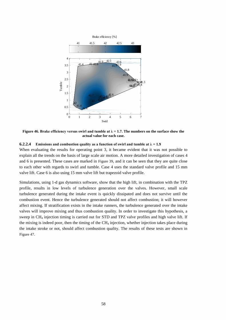
58
Figure 46. Brake efficiency versus swirl and tumble at λ = 1.7. The numbers on the surface show the
actual value for each case.
6.2.2.4 Emissions and combustion quality as a function of swirl and tumble at λ = 1.9
When evaluating the results for operating point 3, it became evident that it was not possible to
explain all the trends on the basis of large scale air motion. A more detailed investigation of cases 4
and 6 is presented. These cases are marked in Figure 39, and it can be seen that they are quite close
to each other with regards to swirl and tumble. Case 4 uses the standard valve profile and 15 mm
valve lift. Case 6 is also using 15 mm valve lift but trapezoid valve profile.
Simulations, using 1-d gas dynamics software, show that the high lift, in combination with the TPZ
profile, results in low levels of turbulence generation over the valves. However, small scale
turbulence generated during the intake event is quickly dissipated and does not survive until the
combustion event. Hence the turbulence generated should not affect combustion; it will however
affect mixing. If stratification exists in the intake runners, the turbulence generated over the intake
valves will improve mixing and thus combustion quality. In order to investigate this hypothesis, a
sweep in CH4 injection timing is carried out for STD and TPZ valve profiles and high valve lift. If
the mixing is indeed poor, then the timing of the CH4 injection, whether injection takes place during
the intake stroke or not, should affect combustion quality. The results of these tests are shown in
Figure 47.
43.1
41.6
41.442
41.7
43
41.8
41.6
42.7
40.8
40.8
43.2
42.1
42.4
41.7
42.8
41.3
41.9
41.241
41.1
41.941.941
43.2
42.5
42.3
41.6
41.4
41.4
41.7
42.6
Swirl
Tu
mb
le
0 1 2 3 4 5 6 70
0.5
1
1.5
2
2.5
3
3.5
4
Brake efficiency [%]
41 41.5 42 42.5 43
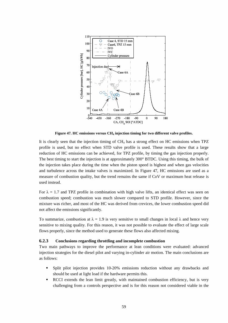
59
Figure 47. HC emissions versus CH4 injection timing for two different valve profiles.
It is clearly seen that the injection timing of CH4 has a strong effect on HC emissions when TPZ
profile is used, but no effect when STD valve profile is used. These results show that a large
reduction of HC emissions can be achieved, for TPZ profile, by timing the gas injection properly.
The best timing to start the injection is at approximately 300° BTDC. Using this timing, the bulk of
the injection takes place during the time when the piston speed is highest and when gas velocities
and turbulence across the intake valves is maximized. In Figure 47, HC emissions are used as a
measure of combustion quality, but the trend remains the same if CoV or maximum heat release is
used instead.
For λ = 1.7 and TPZ profile in combination with high valve lifts, an identical effect was seen on
combustion speed; combustion was much slower compared to STD profile. However, since the
mixture was richer, and most of the HC was derived from crevices, the lower combustion speed did
not affect the emissions significantly.
To summarize, combustion at λ = 1.9 is very sensitive to small changes in local λ and hence very
sensitive to mixing quality. For this reason, it was not possible to evaluate the effect of large scale
flows properly, since the method used to generate these flows also affected mixing.
6.2.3 Conclusions regarding throttling and incomplete combustion
Two main pathways to improve the performance at lean conditions were evaluated: advanced
injection strategies for the diesel pilot and varying in-cylinder air motion. The main conclusions are
as follows:
Split pilot injection provides 10-20% emissions reduction without any drawbacks and
should be used at light load if the hardware permits this.
RCCI extends the lean limit greatly, with maintained combustion efficiency, but is very
challenging from a controls perspective and is for this reason not considered viable in the
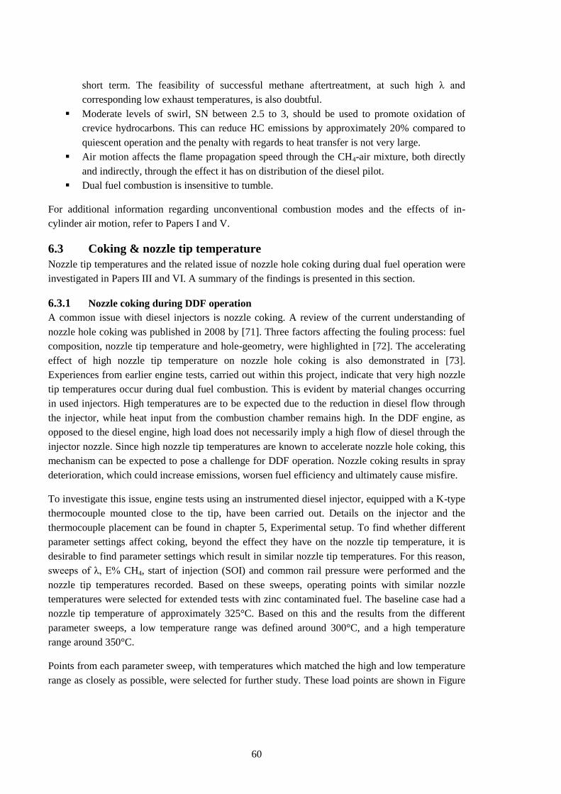
60
short term. The feasibility of successful methane aftertreatment, at such high λ and
corresponding low exhaust temperatures, is also doubtful.
Moderate levels of swirl, SN between 2.5 to 3, should be used to promote oxidation of
crevice hydrocarbons. This can reduce HC emissions by approximately 20% compared to
quiescent operation and the penalty with regards to heat transfer is not very large.
Air motion affects the flame propagation speed through the CH4-air mixture, both directly
and indirectly, through the effect it has on distribution of the diesel pilot.
Dual fuel combustion is insensitive to tumble.
For additional information regarding unconventional combustion modes and the effects of in-
cylinder air motion, refer to Papers I and V.
6.3 Coking & nozzle tip temperature
Nozzle tip temperatures and the related issue of nozzle hole coking during dual fuel operation were
investigated in Papers III and VI. A summary of the findings is presented in this section.
6.3.1 Nozzle coking during DDF operation
A common issue with diesel injectors is nozzle coking. A review of the current understanding of
nozzle hole coking was published in 2008 by [71]. Three factors affecting the fouling process: fuel
composition, nozzle tip temperature and hole-geometry, were highlighted in [72]. The accelerating
effect of high nozzle tip temperature on nozzle hole coking is also demonstrated in [73].
Experiences from earlier engine tests, carried out within this project, indicate that very high nozzle
tip temperatures occur during dual fuel combustion. This is evident by material changes occurring
in used injectors. High temperatures are to be expected due to the reduction in diesel flow through
the injector, while heat input from the combustion chamber remains high. In the DDF engine, as
opposed to the diesel engine, high load does not necessarily imply a high flow of diesel through the
injector nozzle. Since high nozzle tip temperatures are known to accelerate nozzle hole coking, this
mechanism can be expected to pose a challenge for DDF operation. Nozzle coking results in spray
deterioration, which could increase emissions, worsen fuel efficiency and ultimately cause misfire.
To investigate this issue, engine tests using an instrumented diesel injector, equipped with a K-type
thermocouple mounted close to the tip, have been carried out. Details on the injector and the
thermocouple placement can be found in chapter 5, Experimental setup. To find whether different
parameter settings affect coking, beyond the effect they have on the nozzle tip temperature, it is
desirable to find parameter settings which result in similar nozzle tip temperatures. For this reason,
sweeps of λ, E% CH4, start of injection (SOI) and common rail pressure were performed and the
nozzle tip temperatures recorded. Based on these sweeps, operating points with similar nozzle
temperatures were selected for extended tests with zinc contaminated fuel. The baseline case had a
nozzle tip temperature of approximately 325°C. Based on this and the results from the different
parameter sweeps, a low temperature range was defined around 300°C, and a high temperature
range around 350°C.
Points from each parameter sweep, with temperatures which matched the high and low temperature
range as closely as possible, were selected for further study. These load points are shown in Figure
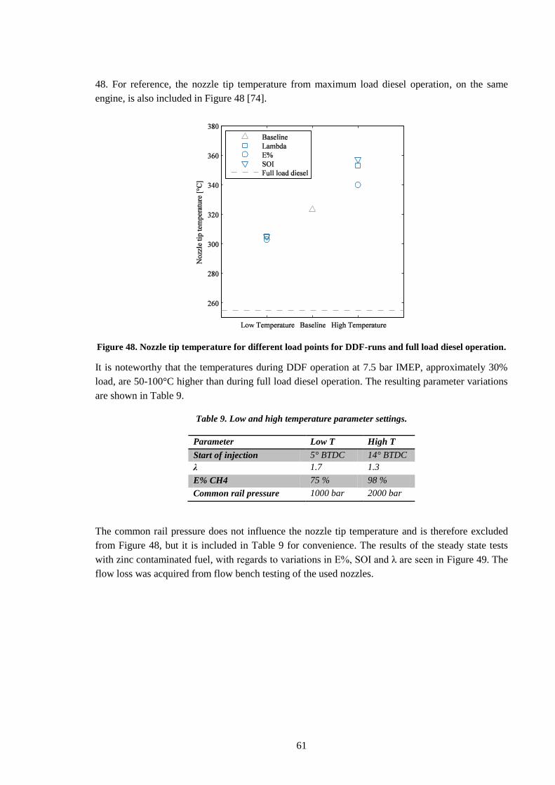
61
48. For reference, the nozzle tip temperature from maximum load diesel operation, on the same
engine, is also included in Figure 48 [74].
Figure 48. Nozzle tip temperature for different load points for DDF-runs and full load diesel operation.
It is noteworthy that the temperatures during DDF operation at 7.5 bar IMEP, approximately 30%
load, are 50-100°C higher than during full load diesel operation. The resulting parameter variations
are shown in Table 9.
Table 9. Low and high temperature parameter settings.
Parameter Low T High T
Start of injection 5° BTDC 14° BTDC
λ 1.7 1.3
E% CH4 75 % 98 %
Common rail pressure 1000 bar 2000 bar
The common rail pressure does not influence the nozzle tip temperature and is therefore excluded
from Figure 48, but it is included in Table 9 for convenience. The results of the steady state tests
with zinc contaminated fuel, with regards to variations in E%, SOI and λ are seen in Figure 49. The
flow loss was acquired from flow bench testing of the used nozzles.
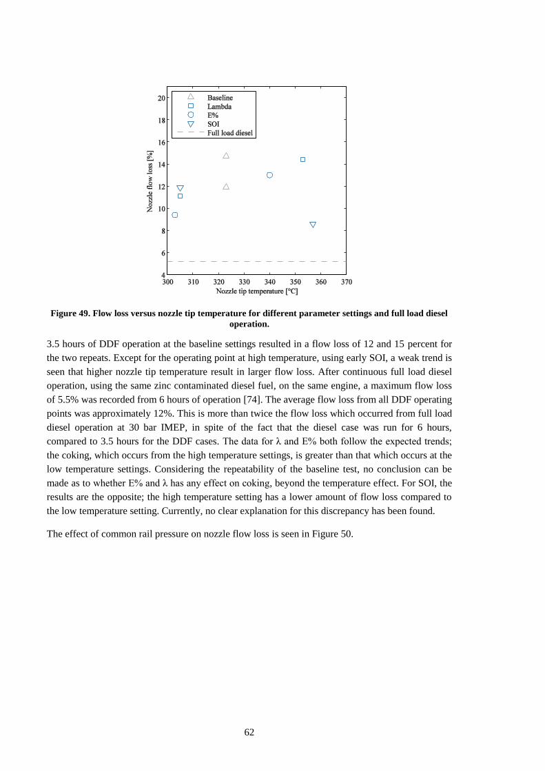
62
Figure 49. Flow loss versus nozzle tip temperature for different parameter settings and full load diesel
operation.
3.5 hours of DDF operation at the baseline settings resulted in a flow loss of 12 and 15 percent for
the two repeats. Except for the operating point at high temperature, using early SOI, a weak trend is
seen that higher nozzle tip temperature result in larger flow loss. After continuous full load diesel
operation, using the same zinc contaminated diesel fuel, on the same engine, a maximum flow loss
of 5.5% was recorded from 6 hours of operation [74]. The average flow loss from all DDF operating
points was approximately 12%. This is more than twice the flow loss which occurred from full load
diesel operation at 30 bar IMEP, in spite of the fact that the diesel case was run for 6 hours,
compared to 3.5 hours for the DDF cases. The data for λ and E% both follow the expected trends;
the coking, which occurs from the high temperature settings, is greater than that which occurs at the
low temperature settings. Considering the repeatability of the baseline test, no conclusion can be
made as to whether E% and λ has any effect on coking, beyond the temperature effect. For SOI, the
results are the opposite; the high temperature setting has a lower amount of flow loss compared to
the low temperature setting. Currently, no clear explanation for this discrepancy has been found.
The effect of common rail pressure on nozzle flow loss is seen in Figure 50.
63
Figure 50. Flow loss due to coking versus common rail pressure.
As previously mentioned, the nozzle tip temperature was the same across all common rail pressures,
and it should therefore not be a factor in explaining the flow loss. It appears that injection pressure
is the parameter that has the largest potential to influence nozzle hole coking. A difference in flow
loss by a factor of two is seen as the injection pressure is increased from 1000 bar to 2000 bar. This
trend has previously been shown for diesel combustion in [75]. The explanation suggested in that
publication is that a higher injection pressure results in increased cavitation and shear stress in the
nozzle holes, which in turn results in improved removal of the nozzle hole deposits. Since the
injected amount was kept constant, the injection duration has increased as the injection pressure is
reduced. This means that the contact time between the fuel and the inside of the nozzle holes has
increased, and it is possible that this can cause an increase in the coking rate.
Comparing SEM imaging from DDF operation at 1000 bar injection pressure, Figure 51, with
imaging from high load diesel operation with a similar injection pressure of 1250 bar, Figure 52,
some differences can be seen.
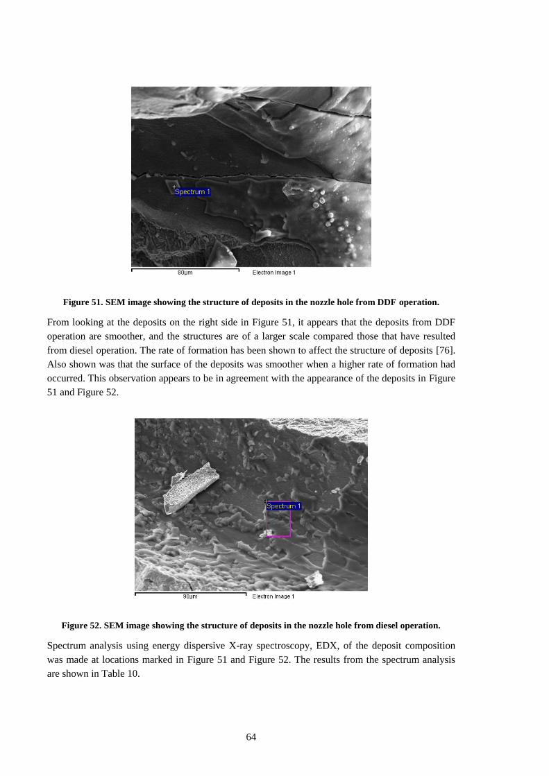
64
Figure 51. SEM image showing the structure of deposits in the nozzle hole from DDF operation.
From looking at the deposits on the right side in Figure 51, it appears that the deposits from DDF
operation are smoother, and the structures are of a larger scale compared those that have resulted
from diesel operation. The rate of formation has been shown to affect the structure of deposits [76].
Also shown was that the surface of the deposits was smoother when a higher rate of formation had
occurred. This observation appears to be in agreement with the appearance of the deposits in Figure
51 and Figure 52.
Figure 52. SEM image showing the structure of deposits in the nozzle hole from diesel operation.
Spectrum analysis using energy dispersive X-ray spectroscopy, EDX, of the deposit composition
was made at locations marked in Figure 51 and Figure 52. The results from the spectrum analysis
are shown in Table 10.
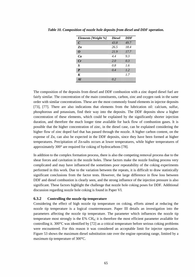
65
Table 10. Composition of nozzle hole deposits from diesel and DDF operation.
Elements [Weight %] Diesel DDF
C
43.8 49.7
Zn 26.5 18.4
O 21.9 17.7
Ca 4.4 9.3
Cr 2.0 0.3
S 0.8 1.6
P 0.4 1.2
K 1.7
Al 0.2
The composition of the deposits from diesel and DDF combustion with a zinc doped diesel fuel are
fairly similar. The concentration of the main constituents, carbon, zinc and oxygen rank in the same
order with similar concentrations. These are the most commonly found elements in injector deposits
[73], [77]. There are also indications that elements from the lubrication oil: calcium, sulfur,
phosphorous and potassium, find their way into the deposits. The DDF deposits show a higher
concentration of these elements, which could be explained by the significantly shorter injection
duration, and therefore the much longer time available for back flow of combustion gases. It is
possible that the higher concentration of zinc, in the diesel case, can be explained considering the
higher flow of zinc doped fuel that has passed through the nozzle. A higher carbon content, on the
expense of Zn, can also be expected in the DDF deposits, since they have been formed at higher
temperatures. Precipitation of Zn-salts occurs at lower temperatures, while higher temperatures of
approximately 300° are required for coking of hydrocarbons [78].
In addition to the complex formation process, there is also the competing removal process due to the
shear forces and cavitation in the nozzle holes. These factors make the nozzle fouling process very
complicated and may have influenced the sometimes poor repeatability of the coking experiments
performed in this work. Due to the variation between the repeats, it is difficult to draw statistically
significant conclusions from the factor tests. However, the large difference in flow loss between
DDF and diesel combustion is clearly seen, and the strong influence of the injection pressure is also
significant. These factors highlight the challenge that nozzle hole coking poses for DDF. Additional
discussion regarding nozzle hole coking is found in Paper VI.
6.3.2 Controlling the nozzle tip temperature
Considering the effect of high nozzle tip temperature on coking, efforts aimed at reducing the
nozzle tip temperature is a logical countermeasure. Paper III details an investigation into the
parameters affecting the nozzle tip temperature. The parameter which influences the nozzle tip
temperature most strongly is the E% CH4; it is therefore the most efficient parameter available for
controlling it. 300°C was identified by [72] as a critical temperature before serious coking problems
were encountered. For this reason it was considered an acceptable limit for injector operation.
Figure 53 shows the maximum diesel substitution rate over the engine operating range, limited by a
maximum tip temperature of 300°C.
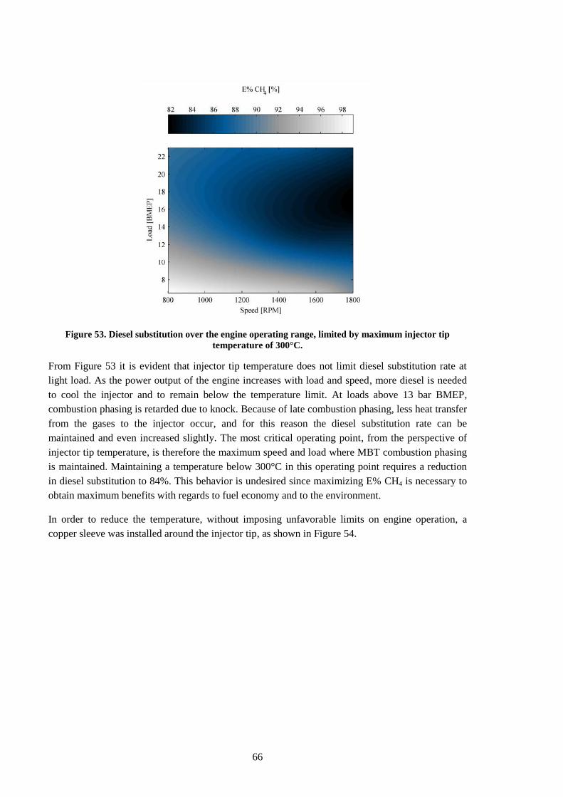
66
Figure 53. Diesel substitution over the engine operating range, limited by maximum injector tip
temperature of 300°C.
From Figure 53 it is evident that injector tip temperature does not limit diesel substitution rate at
light load. As the power output of the engine increases with load and speed, more diesel is needed
to cool the injector and to remain below the temperature limit. At loads above 13 bar BMEP,
combustion phasing is retarded due to knock. Because of late combustion phasing, less heat transfer
from the gases to the injector occur, and for this reason the diesel substitution rate can be
maintained and even increased slightly. The most critical operating point, from the perspective of
injector tip temperature, is therefore the maximum speed and load where MBT combustion phasing
is maintained. Maintaining a temperature below 300°C in this operating point requires a reduction
in diesel substitution to 84%. This behavior is undesired since maximizing E% CH4 is necessary to
obtain maximum benefits with regards to fuel economy and to the environment.
In order to reduce the temperature, without imposing unfavorable limits on engine operation, a
copper sleeve was installed around the injector tip, as shown in Figure 54.
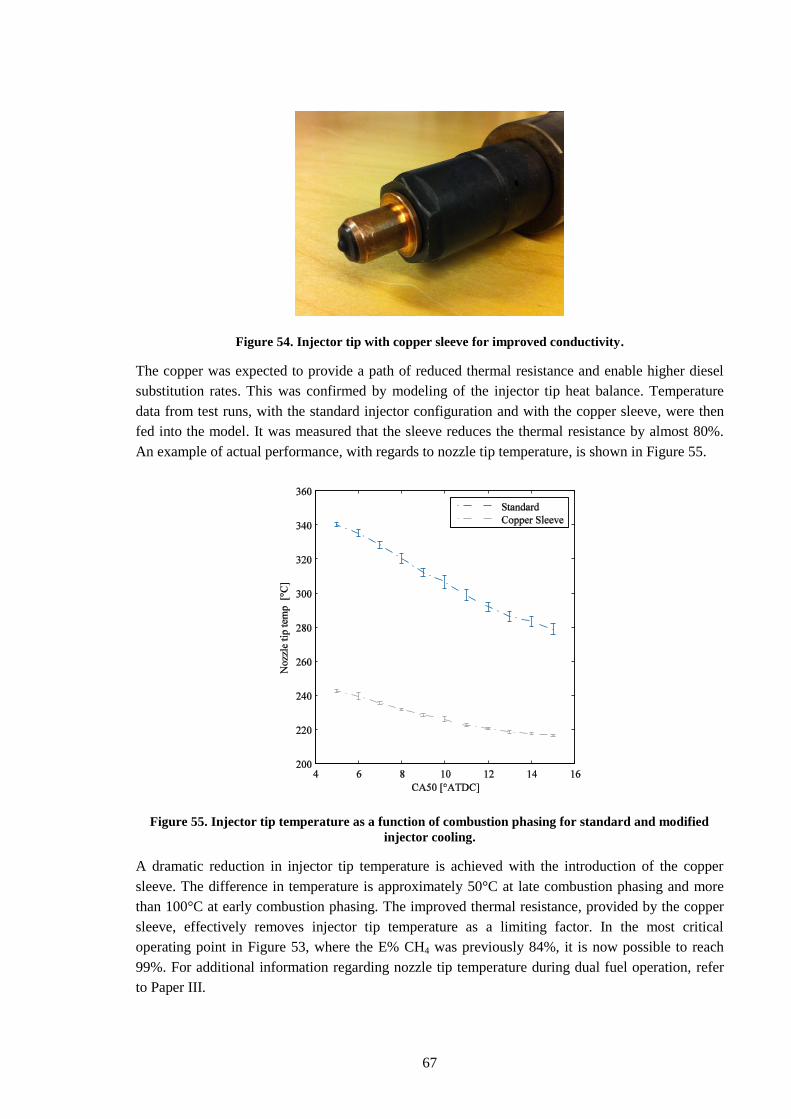
67
Figure 54. Injector tip with copper sleeve for improved conductivity.
The copper was expected to provide a path of reduced thermal resistance and enable higher diesel
substitution rates. This was confirmed by modeling of the injector tip heat balance. Temperature
data from test runs, with the standard injector configuration and with the copper sleeve, were then
fed into the model. It was measured that the sleeve reduces the thermal resistance by almost 80%.
An example of actual performance, with regards to nozzle tip temperature, is shown in Figure 55.
Figure 55. Injector tip temperature as a function of combustion phasing for standard and modified
injector cooling.
A dramatic reduction in injector tip temperature is achieved with the introduction of the copper
sleeve. The difference in temperature is approximately 50°C at late combustion phasing and more
than 100°C at early combustion phasing. The improved thermal resistance, provided by the copper
sleeve, effectively removes injector tip temperature as a limiting factor. In the most critical
operating point in Figure 53, where the E% CH4 was previously 84%, it is now possible to reach
99%. For additional information regarding nozzle tip temperature during dual fuel operation, refer
to Paper III.
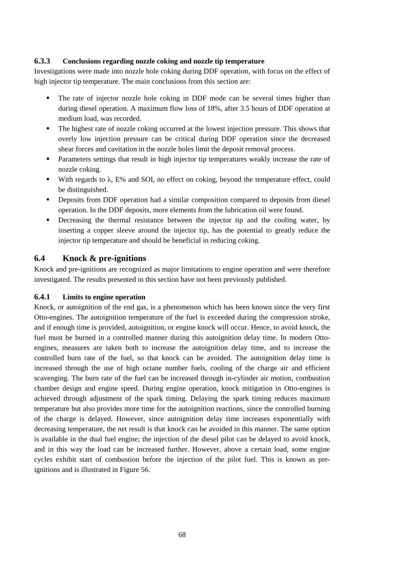
68
6.3.3 Conclusions regarding nozzle coking and nozzle tip temperature
Investigations were made into nozzle hole coking during DDF operation, with focus on the effect of
high injector tip temperature. The main conclusions from this section are:
The rate of injector nozzle hole coking in DDF mode can be several times higher than
during diesel operation. A maximum flow loss of 18%, after 3.5 hours of DDF operation at
medium load, was recorded.
The highest rate of nozzle coking occurred at the lowest injection pressure. This shows that
overly low injection pressure can be critical during DDF operation since the decreased
shear forces and cavitation in the nozzle holes limit the deposit removal process.
Parameters settings that result in high injector tip temperatures weakly increase the rate of
nozzle coking.
With regards to λ, E% and SOI, no effect on coking, beyond the temperature effect, could
be distinguished.
Deposits from DDF operation had a similar composition compared to deposits from diesel
operation. In the DDF deposits, more elements from the lubrication oil were found.
Decreasing the thermal resistance between the injector tip and the cooling water, by
inserting a copper sleeve around the injector tip, has the potential to greatly reduce the
injector tip temperature and should be beneficial in reducing coking.
6.4 Knock & pre-ignitions
Knock and pre-ignitions are recognized as major limitations to engine operation and were therefore
investigated. The results presented in this section have not been previously published.
6.4.1 Limits to engine operation
Knock, or autoignition of the end gas, is a phenomenon which has been known since the very first
Otto-engines. The autoignition temperature of the fuel is exceeded during the compression stroke,
and if enough time is provided, autoignition, or engine knock will occur. Hence, to avoid knock, the
fuel must be burned in a controlled manner during this autoignition delay time. In modern Otto-
engines, measures are taken both to increase the autoignition delay time, and to increase the
controlled burn rate of the fuel, so that knock can be avoided. The autoignition delay time is
increased through the use of high octane number fuels, cooling of the charge air and efficient
scavenging. The burn rate of the fuel can be increased through in-cylinder air motion, combustion
chamber design and engine speed. During engine operation, knock mitigation in Otto-engines is
achieved through adjustment of the spark timing. Delaying the spark timing reduces maximum
temperature but also provides more time for the autoignition reactions, since the controlled burning
of the charge is delayed. However, since autoignition delay time increases exponentially with
decreasing temperature, the net result is that knock can be avoided in this manner. The same option
is available in the dual fuel engine; the injection of the diesel pilot can be delayed to avoid knock,
and in this way the load can be increased further. However, above a certain load, some engine
cycles exhibit start of combustion before the injection of the pilot fuel. This is known as pre-
ignitions and is illustrated in Figure 56.
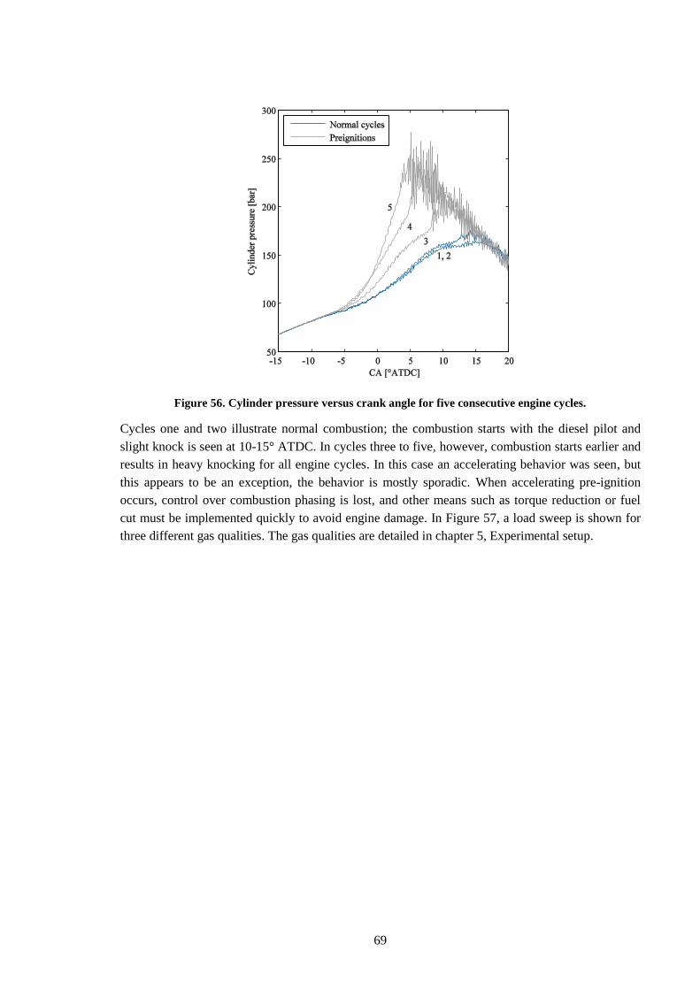
69
Figure 56. Cylinder pressure versus crank angle for five consecutive engine cycles.
Cycles one and two illustrate normal combustion; the combustion starts with the diesel pilot and
slight knock is seen at 10-15° ATDC. In cycles three to five, however, combustion starts earlier and
results in heavy knocking for all engine cycles. In this case an accelerating behavior was seen, but
this appears to be an exception, the behavior is mostly sporadic. When accelerating pre-ignition
occurs, control over combustion phasing is lost, and other means such as torque reduction or fuel
cut must be implemented quickly to avoid engine damage. In Figure 57, a load sweep is shown for
three different gas qualities. The gas qualities are detailed in chapter 5, Experimental setup.
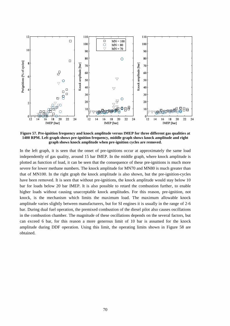
70
Figure 57. Pre-ignition frequency and knock amplitude versus IMEP for three different gas qualities at
1400 RPM. Left graph shows pre-ignition frequency, middle graph shows knock amplitude and right
graph shows knock amplitude when pre-ignition cycles are removed.
In the left graph, it is seen that the onset of pre-ignitions occur at approximately the same load
independently of gas quality, around 15 bar IMEP. In the middle graph, where knock amplitude is
plotted as function of load, it can be seen that the consequence of these pre-ignitions is much more
severe for lower methane numbers. The knock amplitude for MN70 and MN80 is much greater than
that of MN100. In the right graph the knock amplitude is also shown, but the pre-ignition-cycles
have been removed. It is seen that without pre-ignitions, the knock amplitude would stay below 10
bar for loads below 20 bar IMEP. It is also possible to retard the combustion further, to enable
higher loads without causing unacceptable knock amplitudes. For this reason, pre-ignition, not
knock, is the mechanism which limits the maximum load. The maximum allowable knock
amplitude varies slightly between manufacturers, but for SI engines it is usually in the range of 2-6
bar. During dual fuel operation, the premixed combustion of the diesel pilot also causes oscillations
in the combustion chamber. The magnitude of these oscillations depends on the several factors, but
can exceed 6 bar, for this reason a more generous limit of 10 bar is assumed for the knock
amplitude during DDF operation. Using this limit, the operating limits shown in Figure 58 are
obtained.
71
Figure 58. Load target and limits versus engine speed for three different gas qualities.
The target level is based on pure diesel operation from a Scania production diesel engine. For
maximum market acceptance it is highly desirable to reach the same torque levels as the
corresponding diesel engines. While higher gas qualities are definitely desirable, it is likely that the
vehicle needs to function with methane numbers as low as 70. Using MN70 fuel, due to pre-
ignitions, the load is limited to approximately 65% of the target level. It is clear that the issue of
pre-ignitions is something which needs to be overcome, if development of attractive dual fuel
engines is to be possible.
6.4.2 Phenomenology
A simple model for autoignition is the well-known Livengood-Wu-integral [79]:
∫
( )
( 1 )
Where the ignition delay, τ, is given as:
( 2 )
When the integral reaches unity autoignition occurs. If the zone of autoignition is large enough, a
propagating flame can origin from the autoignition zone, this would constitute a pre-ignition. In this
expression, A, B and n are parameters related to the chemistry of the mixture while pressure, p, and
temperature, T, are related to engine operation. Different occurrences during engine operation,
which influence these parameters and allow the integral to reach unity before the desired start of
combustion, can therefore cause pre-ignitions. The following root causes are documented in
literature:
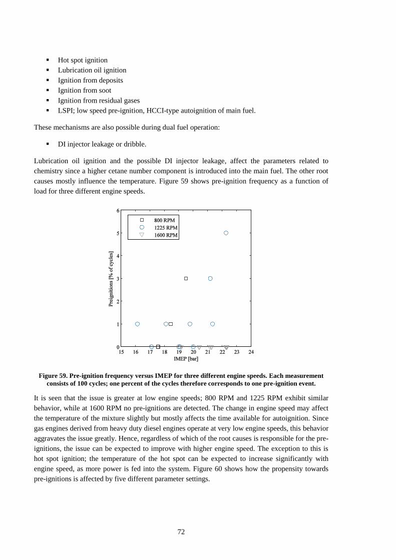
72
Hot spot ignition
Lubrication oil ignition
Ignition from deposits
Ignition from soot
Ignition from residual gases
LSPI; low speed pre-ignition, HCCI-type autoignition of main fuel.
These mechanisms are also possible during dual fuel operation:
DI injector leakage or dribble.
Lubrication oil ignition and the possible DI injector leakage, affect the parameters related to
chemistry since a higher cetane number component is introduced into the main fuel. The other root
causes mostly influence the temperature. Figure 59 shows pre-ignition frequency as a function of
load for three different engine speeds.
Figure 59. Pre-ignition frequency versus IMEP for three different engine speeds. Each measurement
consists of 100 cycles; one percent of the cycles therefore corresponds to one pre-ignition event.
It is seen that the issue is greater at low engine speeds; 800 RPM and 1225 RPM exhibit similar
behavior, while at 1600 RPM no pre-ignitions are detected. The change in engine speed may affect
the temperature of the mixture slightly but mostly affects the time available for autoignition. Since
gas engines derived from heavy duty diesel engines operate at very low engine speeds, this behavior
aggravates the issue greatly. Hence, regardless of which of the root causes is responsible for the pre-
ignitions, the issue can be expected to improve with higher engine speed. The exception to this is
hot spot ignition; the temperature of the hot spot can be expected to increase significantly with
engine speed, as more power is fed into the system. Figure 60 shows how the propensity towards
pre-ignitions is affected by five different parameter settings.
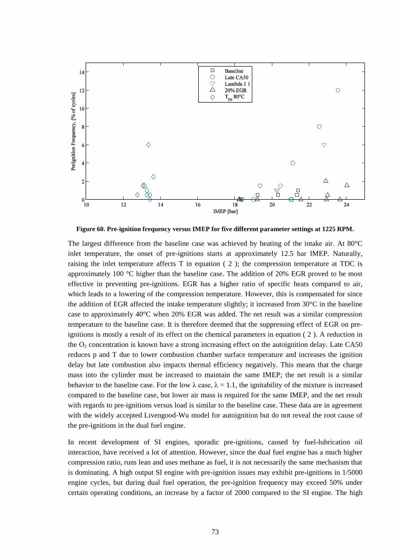
73
Figure 60. Pre-ignition frequency versus IMEP for five different parameter settings at 1225 RPM.
The largest difference from the baseline case was achieved by heating of the intake air. At 80°C
inlet temperature, the onset of pre-ignitions starts at approximately 12.5 bar IMEP. Naturally,
raising the inlet temperature affects T in equation ( 2 ); the compression temperature at TDC is
approximately 100 °C higher than the baseline case. The addition of 20% EGR proved to be most
effective in preventing pre-ignitions. EGR has a higher ratio of specific heats compared to air,
which leads to a lowering of the compression temperature. However, this is compensated for since
the addition of EGR affected the intake temperature slightly; it increased from 30°C in the baseline
case to approximately 40°C when 20% EGR was added. The net result was a similar compression
temperature to the baseline case. It is therefore deemed that the suppressing effect of EGR on pre-
ignitions is mostly a result of its effect on the chemical parameters in equation ( 2 ). A reduction in
the O2 concentration is known have a strong increasing effect on the autoignition delay. Late CA50
reduces p and T due to lower combustion chamber surface temperature and increases the ignition
delay but late combustion also impacts thermal efficiency negatively. This means that the charge
mass into the cylinder must be increased to maintain the same IMEP; the net result is a similar
behavior to the baseline case. For the low λ case, λ = 1.1, the ignitability of the mixture is increased
compared to the baseline case, but lower air mass is required for the same IMEP, and the net result
with regards to pre-ignitions versus load is similar to the baseline case. These data are in agreement
with the widely accepted Livengood-Wu model for autoignition but do not reveal the root cause of
the pre-ignitions in the dual fuel engine.
In recent development of SI engines, sporadic pre-ignitions, caused by fuel-lubrication oil
interaction, have received a lot of attention. However, since the dual fuel engine has a much higher
compression ratio, runs lean and uses methane as fuel, it is not necessarily the same mechanism that
is dominating. A high output SI engine with pre-ignition issues may exhibit pre-ignitions in 1/5000
engine cycles, but during dual fuel operation, the pre-ignition frequency may exceed 50% under
certain operating conditions, an increase by a factor of 2000 compared to the SI engine. The high
74
frequency of pre-ignitions during dual fuel operation, and the fact that an accelerating behavior is
sometimes seen, could indicate that more traditional pre-ignition from hot spots is occurring.
6.4.3 Hot spot ignition
Since the DDF engine lacks spark plug, it is not clear which component would be responsible for
the hot spot ignition. The critical spark plug temperature before onset of pre-ignition versus
compression ratio, for a naturally aspirated SI engine at full load, was investigated in [56]. The
critical temperature was in the range of 970-1070°C and decreased by approximately 50°C per unit
of increasing compression ratio. Other authors report critical temperatures in the range of 800-
900°C [80]. It is unlikely that any component in the lean burning DDF engine reaches temperatures
in this range. However, since the critical temperature is a function of pressure and the DDF engine
has a much higher compression ratio than the gasoline engine, it is probable that lower component
temperatures are needed to trigger pre-ignitions. Since a spark plug was lacking, and the
temperature of the nozzle tip is well documented in chapter 6.3 and significantly below this
temperature range, it was considered that the hottest surface in contact with the gas most likely
belonged to the exhaust valves, and that excessive exhaust valve temperature might be the root
cause for the pre-ignitions. Simulations of full load diesel operation indicate that exhaust valve
temperature approaches 750° in the most demanding operating point. This temperature is also below
the critical temperature range mentioned above but since the effect of pressure on hot spot ignition
is not documented for the relevant pressure range [80], ignition from the exhaust valves could not
be ruled out and was considered a possible root cause. In order to test this hypothesis, the standard
valves were replaced with sodium cooled exhaust valves, and a load sweep was performed.
Empirically, sodium cooled valves will run approximately 100° cooler than the corresponding
standard valves, and the tendency towards pre-ignitions should be significantly reduced. The results
from this load sweep are seen in Figure 61.
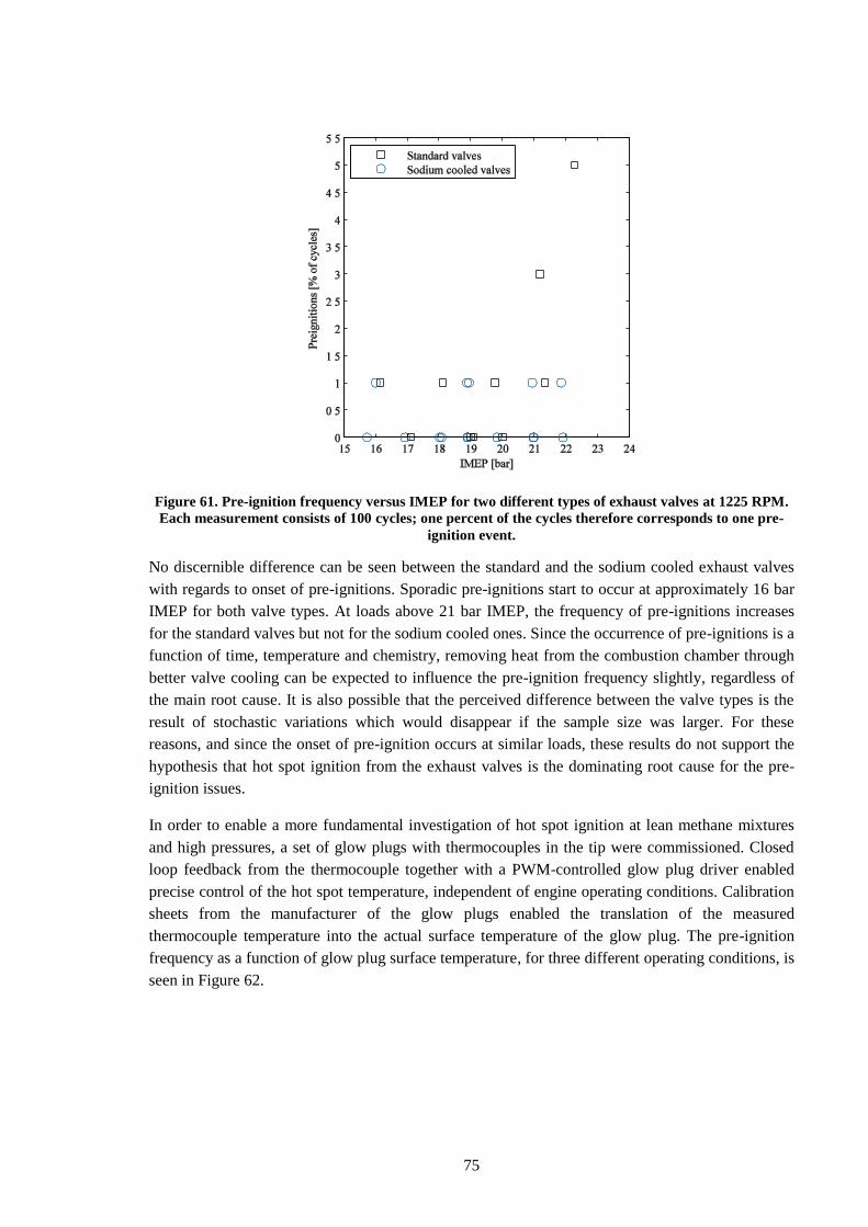
75
Figure 61. Pre-ignition frequency versus IMEP for two different types of exhaust valves at 1225 RPM.
Each measurement consists of 100 cycles; one percent of the cycles therefore corresponds to one pre-
ignition event.
No discernible difference can be seen between the standard and the sodium cooled exhaust valves
with regards to onset of pre-ignitions. Sporadic pre-ignitions start to occur at approximately 16 bar
IMEP for both valve types. At loads above 21 bar IMEP, the frequency of pre-ignitions increases
for the standard valves but not for the sodium cooled ones. Since the occurrence of pre-ignitions is a
function of time, temperature and chemistry, removing heat from the combustion chamber through
better valve cooling can be expected to influence the pre-ignition frequency slightly, regardless of
the main root cause. It is also possible that the perceived difference between the valve types is the
result of stochastic variations which would disappear if the sample size was larger. For these
reasons, and since the onset of pre-ignition occurs at similar loads, these results do not support the
hypothesis that hot spot ignition from the exhaust valves is the dominating root cause for the pre-
ignition issues.
In order to enable a more fundamental investigation of hot spot ignition at lean methane mixtures
and high pressures, a set of glow plugs with thermocouples in the tip were commissioned. Closed
loop feedback from the thermocouple together with a PWM-controlled glow plug driver enabled
precise control of the hot spot temperature, independent of engine operating conditions. Calibration
sheets from the manufacturer of the glow plugs enabled the translation of the measured
thermocouple temperature into the actual surface temperature of the glow plug. The pre-ignition
frequency as a function of glow plug surface temperature, for three different operating conditions, is
seen in Figure 62.
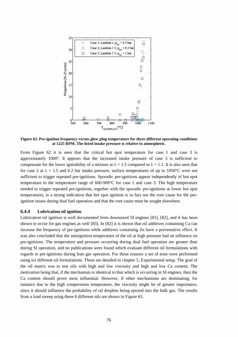
76
Figure 62. Pre-ignition frequency versus glow plug temperature for three different operating conditions
at 1225 RPM. The listed intake pressure is relative to atmospheric.
From Figure 62 it is seen that the critical hot spot temperature for case 1 and case 3 is
approximately 1000°. It appears that the increased intake pressure of case 3 is sufficient to
compensate for the lower ignitability of a mixture at λ = 1.5 compared to λ = 1.1. It is also seen that
for case 2 at λ = 1.5 and 0.2 bar intake pressure, surface temperatures of up to 1050°C were not
sufficient to trigger repeated pre-ignitions. Sporadic pre-ignitions appear independently of hot spot
temperature in the temperature range of 600-900°C for case 1 and case 3. The high temperature
needed to trigger repeated pre-ignitions, together with the sporadic pre-ignitions at lower hot spot
temperatures, is a strong indication that hot spot ignition is in fact not the root cause for the pre-
ignition issues during dual fuel operation and that the root cause must be sought elsewhere.
6.4.4 Lubrication oil ignition
Lubrication oil ignition is well documented from downsized SI engines [81], [82], and it has been
shown to occur for gas engines as well [83]. In [82] it is shown that oil additives containing Ca can
increase the frequency of pre-ignitions while additives containing Zn have a preventative effect. It
was also concluded that the autoignition temperature of the oil at high pressure had an influence on
pre-ignitions. The temperature and pressure occurring during dual fuel operation are greater than
during SI operation, and no publications were found which evaluate different oil formulations with
regards to pre-ignitions during lean gas operation. For these reasons a set of tests were performed
using six different oil formulations. These are detailed in chapter 5, Experimental setup. The goal of
the oil matrix was to test oils with high and low viscosity and high and low Ca content. The
motivation being that, if the mechanism is identical to that which is occurring in SI engines, then the
Ca content should prove most influential. However, if other mechanisms are dominating, for
instance due to the high compression temperature, the viscosity might be of greater importance,
since it should influence the probability of oil droplets being ejected into the bulk gas. The results
from a load sweep using these 6 different oils are shown in Figure 63.
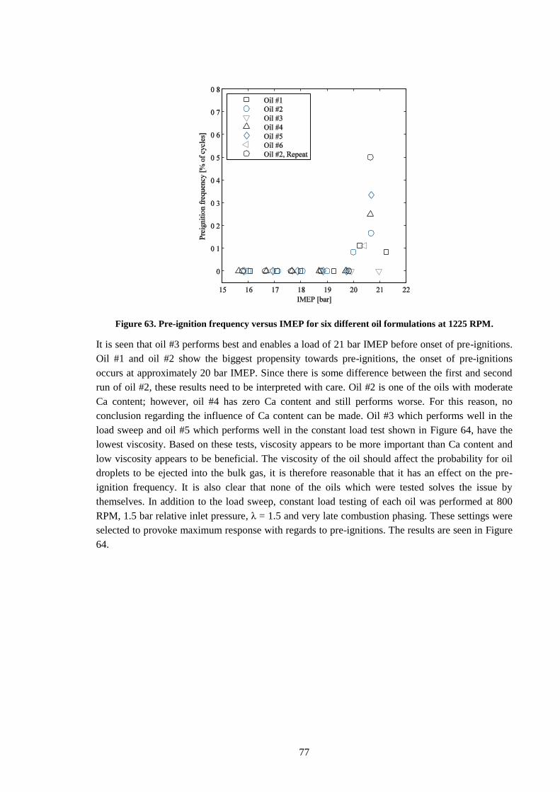
77
Figure 63. Pre-ignition frequency versus IMEP for six different oil formulations at 1225 RPM.
It is seen that oil #3 performs best and enables a load of 21 bar IMEP before onset of pre-ignitions.
Oil #1 and oil #2 show the biggest propensity towards pre-ignitions, the onset of pre-ignitions
occurs at approximately 20 bar IMEP. Since there is some difference between the first and second
run of oil #2, these results need to be interpreted with care. Oil #2 is one of the oils with moderate
Ca content; however, oil #4 has zero Ca content and still performs worse. For this reason, no
conclusion regarding the influence of Ca content can be made. Oil #3 which performs well in the
load sweep and oil #5 which performs well in the constant load test shown in Figure 64, have the
lowest viscosity. Based on these tests, viscosity appears to be more important than Ca content and
low viscosity appears to be beneficial. The viscosity of the oil should affect the probability for oil
droplets to be ejected into the bulk gas, it is therefore reasonable that it has an effect on the pre-
ignition frequency. It is also clear that none of the oils which were tested solves the issue by
themselves. In addition to the load sweep, constant load testing of each oil was performed at 800
RPM, 1.5 bar relative inlet pressure, λ = 1.5 and very late combustion phasing. These settings were
selected to provoke maximum response with regards to pre-ignitions. The results are seen in Figure
64.
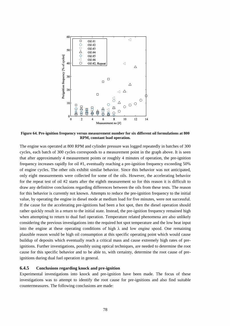
78
Figure 64. Pre-ignition frequency versus measurement number for six different oil formulations at 800
RPM, constant load operation.
The engine was operated at 800 RPM and cylinder pressure was logged repeatedly in batches of 300
cycles, each batch of 300 cycles corresponds to a measurement point in the graph above. It is seen
that after approximately 4 measurement points or roughly 4 minutes of operation, the pre-ignition
frequency increases rapidly for oil #1, eventually reaching a pre-ignition frequency exceeding 50%
of engine cycles. The other oils exhibit similar behavior. Since this behavior was not anticipated,
only eight measurements were collected for some of the oils. However, the accelerating behavior
for the repeat test of oil #2 starts after the eighth measurement so for this reason it is difficult to
draw any definitive conclusions regarding differences between the oils from these tests. The reason
for this behavior is currently not known. Attempts to reduce the pre-ignition frequency to the initial
value, by operating the engine in diesel mode at medium load for five minutes, were not successful.
If the cause for the accelerating pre-ignitions had been a hot spot, then the diesel operation should
rather quickly result in a return to the initial state. Instead, the pre-ignition frequency remained high
when attempting to return to dual fuel operation. Temperature related phenomena are also unlikely
considering the previous investigations into the required hot spot temperature and the low heat input
into the engine at these operating conditions of high λ and low engine speed. One remaining
plausible reason would be high oil consumption at this specific operating point which would cause
buildup of deposits which eventually reach a critical mass and cause extremely high rates of pre-
ignitions. Further investigations, possibly using optical techniques, are needed to determine the root
cause for this specific behavior and to be able to, with certainty, determine the root cause of pre-
ignitions during dual fuel operation in general.
6.4.5 Conclusions regarding knock and pre-ignition
Experimental investigations into knock and pre-ignition have been made. The focus of these
investigations was to attempt to identify the root cause for pre-ignitions and also find suitable
countermeasures. The following conclusions are made:
79
Pre-ignitions, rather than knock, limit the load. This holds for fuels with methane number in
the range of 70-100. The behavior is most severe at low engine speeds in combination with
retarded combustion phasing.
EGR is the most effective countermeasure to pre-ignition.
The temperature required for hot spot ignition was found to be approximately 1000°. This
result, in combination with the lack of influence on the onset of pre-ignitions as the exhaust
valves were replaced with sodium cooled valves, makes hot spot ignition an unlikely root
cause for the pre-ignition issues.
Influence of lubrication oil quality on pre-ignition frequency is seen. However, none of the
tested oils had sufficient resistance towards pre-ignitions to solve the issue by itself. Further
work is required. Oil originated ignition is currently the most probable root cause but other
phenomena, such as DI injector dribble, cannot be ruled out.
Accelerating pre-ignition frequency occurs during constant load operation at 800 RPM, the
cause for this behavior is currently not known with certainty but a buildup of deposits is
likely.
80
7 Discussion
The discussion will attempt to tie the results from the project together into suggestions for the
design of a competitive dual fuel engine.
7.1 Hardware
These are the recommendations regarding the hardware configuration based on the results of the
project and on available literature.
7.1.1 Aftertreatment
The methane aftertreatment is what sets the boundary conditions for engine operations with regards
to HC emissions and exhaust temperature. For this reason it needs to be discussed first. The biggest
challenge regarding aftertreatment is the high exhaust temperature required by the methane
oxidation catalyst. Light-off temperature has historically been around 450°C. Development is
ongoing, however, and current prototype catalysts feature light-off temperature as low as 300°C for
a new catalyst and 350°C for an aged one. Another 50°C need to be added to the light-off
temperature to reach maximum conversion. This would mean that, for an aged, modern catalyst,
400°C is the lowest tolerable exhaust temperature at the catalyst inlet.
As HC and CO are converted in the catalyst in an exothermic reaction, heat is produced. Different
methods have been proposed to keep the heat from these reactions in the catalyst to enable
operation at exhaust temperatures below the light-off temperature. If the flow direction of exhaust
through the catalyst is cycled, the heat will remain in the catalyst to a much greater extent, resulting
in high conversion efficiency at exhaust temperatures as low as 262°C [84]. These results are from
the year 2000, so it is likely that the catalyst used in the study required at least 450°C for efficient
methane conversion. This indicates that the cycling of the exhaust flow direction enables exhaust
temperatures approximately 200° below what would otherwise be acceptable. Similarly, the catalyst
can be arranged as a heat exchanger, where the flow is reversed inside the catalyst and the hot
products will heat the incoming gases. No data is found regarding the performance of the latter
configuration, but it can be assumed that it should be similar to the cycling-flow catalyst. If a heat
exchanger configuration is applied to a state-of-the art catalyst with a minimum of 400° operating
temperature, this translates into a lowest exhaust gas temperature of 200° at the catalyst inlet. If a
150° temperature drop across the turbocharger is assumed, this would mean a minimum allowable
exhaust temperature of 350° in the exhaust manifold, 400° after the addition of a 50° safety margin.
This translates into a λ of approximately 1.6 at light load at a compression ratio of 17.3. Assuming a
conservative conversion efficiency of 90% over a cycle and a legislated limit of 0.5 g/kWh for HC,
then the maximum allowable engine-out HC emissions are 5 g/kWh. Based on this reasoning and
with some additional safety margin, the target for engine-out HC emissions is set to 4 g/kWh. At
25% load, λ = 1.6 and high E% CH4, engine-out HC emissions are approximately 6 g/kWh using the
current engine configuration. Hence, changes to the engine which lower the engine-out HC
emissions by approximately a third of the present level are needed.
The DPF and the NOx aftertreatment are carried over from the base diesel engine. Soot levels during
DDF combustion are generally much lower than during diesel operation, but it is unlikely that the
Euro 6 emissions level can be met without a DPF, especially with regards to particle number.
Regardless of performance in DDF mode, the DPF is needed for diesel operation if fuel flexibility
81
should be maintained. The NOx levels are of the same order of magnitude as during diesel operation
and should therefore be manageable by the SCR system.
7.1.2 Fuel system
The diesel injection system should be of the common rail type to enable maximum degrees of
freedom. Multiple injections are a key tool to increase the combustion efficiency at light load.
Capability for late injections to increase the exhaust temperature and enable quick light-off of the
oxidation catalyst is another important application for a common rail system. The diesel injector
could be fitted with a copper sleeve around the tip to lower the nozzle tip temperature and reduce
the risk of rapid nozzle hole coking. The copper sleeve allowed for operation at high E% CH4 with
tolerable nozzle tip temperatures.
The port injectors for the CH4 should be fitted with extensions to the nozzles extending into the port
and enabling injection as close as possible to the back of the intake valves. The nozzles should be
large enough so that the injection duration during full load operation does not exceed the opening
duration of the intake valve. This configuration enables the entire injection to take place during the
intake event, creating best possible mixing between the CH4 and the air. The second benefit of this
arrangement is that very little CH4 resides in the intake runners between cycles, which means that
large cycle-to-cycle changes in CH4 amount are possible with good control of in-cylinder λ. Firstly,
this enables rapid reduction in E% CH4 as countermeasure when pre-ignition is detected. Compared
to torque reduction, this has the benefit that engine output remains unaffected. If it is done correctly,
the driver will not notice any reduction in performance. Injection on open intake valve also enables
better λ-control during transients. This is important for reducing HC emissions; a state-of-the-art
oxidation catalyst has close to 100% conversion efficiency for CH4 in steady state. Over a transient
cycle, however, conversion efficiency for the same catalyst drops to just above 90%. A probable
cause for this reduction in efficiency is surges in HC concentration resulting from poor λ-control
during transients. Such surges are also likely to accelerate the ageing process of the catalyst since
they can cause excessive local temperatures. For these reasons, precise cycle-to-cycle control of λ is
crucial.
7.1.3 Compression ratio
The compression ratio in the dual fuel engine is a trade-off between two conflicting needs. It needs
to be high enough to enable reliable autoignition of the high cetane number fuel, the diesel. It also
needs to be low enough to enable high load operation without the occurrence of autoignition, knock,
of the low cetane number fuel, the methane. Some guidance to this trade-off can be found by
examining marine, purpose-built, dual fuel engines. These have a compression ratio of
approximately 14. However, the large-bore marine engines use a small injector to inject the pilot
fuel, and hence have a much longer path of flame propagation through the methane. This factor, in
combination with the low engine speed, means that they are more susceptible to knock than
transient truck engines. Marine engines are also not cold-started frequently, so the ignitability of the
pilot fuel is of lesser concern. These two factors combined, mean that the optimal compression ratio
for a transient heavy duty engine is likely to be greater than 14. The base diesel engine used in this
study has a compression ratio of 17.3 and achieves cold starts without any starting aids such as glow
plugs or intake air heating. This is therefore seen as the upper limit to the range of compression
ratios. The optimal compression ratio for a heavy duty dual fuel engine is therefore found in the
82
range of 14-17. A reasonable best guess would be a compression ratio of 16, but since this
parameter has not been specifically investigated in this project, a more precise recommendation
cannot be given. A variable valve train which enables online variation of the effective compression
ratio would appear ideal for the dual fuel application.
7.1.4 Piston & rings
If fuel flexibility is to be maintained, meaning that diesel operation should still be possible,
modifying the shape of the combustion chamber would be costly since the diesel calibration would
have to be repeated. From the tests with varying air motion it appears that dual fuel combustion is
relatively insensitive to tumble. It is plausible that the turbulence generated by the diesel injection in
combination with the large ignition source means that sufficient energy is available regardless of
tumble. This in turn would imply that the design of the combustion chamber with regards to
turbulence generation is of little importance. The shape of the piston bowl is therefore left intact. A
redesign of the piston ring land is important, however. This redesign should serve two goals,
reducing oil consumption and minimizing the topland volume.
Designing the ring-pack is a trade-off between wear, oil consumption and friction. Since pre-
ignitions currently impose unacceptable limits to engine operation and the likely root cause is
lubrication oil related ignition, minimizing oil consumption would have to take priority over wear
and friction. The goal could be to reduce the pre-ignition frequency to a tenth of the current levels
through reduced lubrication oil consumption.
Since the main source of HC emissions is the piston topland volume, a redesign of the piston ring
land would aim to reduce this volume as far as possible; the target being a minimum of 50 percent
reduction. One way of reducing the topland volume is to move the top compression ring upwards,
thus reducing the topland height. The position of the top compression ring is limited by
temperature; if the temperature is too high, coking of the lubrication oil will occur which cannot be
allowed. However, if the maximum torque in diesel mode is reduced there would be less heat input
into the inside of the piston bowl and the maximum piston temperatures would be lower. This, in
turn would enable the top ring to be moved upwards. A 50% reduction in topland volume would
translate into a reduction in HC emissions of approximately 25%, or 1.5 g/kWh at light load and λ =
1.6.
7.1.5 Lubrication oil
The lubrication oil is specified in the usual manner with the additional demand that it should also
resist pre-ignitions to the greatest extent possible. Based on available literature, this translates into
low Ca-content, high Zn-content and a base oil with high resistance against autoignition. From the
results in this project, low viscosity also appears beneficial.
7.1.6 Air path
A throttle must be added in case this is lacking from the base diesel engine to enable λ control at
light load.
The port design of the cylinder head should create a swirl number of approximately 3. The reason
for this relatively high swirl is that it helps mix hydrocarbons returning from crevices and for this
reason it has a reducing effect on the hydrocarbon emissions. It is assumed that choosing the
83
appropriate swirl can lower the HC emissions by 10% compared to the current configuration. This
would translate into a reduction of approximately 0.5 g/kWh at light load and λ = 1.6.
Variable intake valve timing would be extremely valuable. This would enable variation of the
effective compression ratio through Miller-timing and late closing of the intake valves. At light
load, a high compression ratio leads to lower ignition delay of the diesel pilot which in turn enables
lower loads before having to resort to diesel operation. Higher compression ratio also helps
combustion efficiency in the lean CH4-air mixture. At high load a reduced compression ratio helps
greatly to reduce the issues with pre-ignition and knock. Variable valve timing is not yet
implemented in heavy duty diesel engines and therefore the cost of adding it as part of the
conversion to dual fuel operation would be substantial. For this reason, it is considered optional.
7.2 Software and calibration
One of the main tasks during calibration will be to provide sufficient thermal management so that
the oxidation catalyst can work at high conversion efficiency without excessive ageing. This is
mainly a matter of controlling λ with high precision. In addition to λ-control, adjusting the
combustion phasing or adding post injections of diesel are other tools for thermal management. At
the lowest loads and idling where the throttling required would cause misfire of the diesel pilot,
pure diesel operation is utilized.
An injection strategy using multiple injections should be used at light load. Splitting the pilot
injection into two, with most of the fuel allocated to the first injection, improves combustion
efficiency and reduces the amount of HC emissions by approximately 10%. At 25% load and λ =
1.6 this means a reduction in engine-out HC by 0.5 g/kWh.
In order to minimize the rate of nozzle hole coking in dual fuel mode, the common rail pressure
should be kept as high as possible. It is also possible that intermittent operation using 100% diesel
and high injection pressure can be used to clean the nozzles from deposits through cavitation. This
effect is so far hypothetical since it has not been investigated but it is likely that this would occur to
some extent.
The control system must be able to detect pre-ignitions. The simplest way to achieve this would be
through the use of a knock sensor. The knock sensor would only detect pre-ignition cycles which
lead to knock but this can be considered sufficient. If sudden, single knocking cycles are detected, a
rapid switch to a lower E% CH4 should be made to avoid repeated pre-ignitions. The switch is made
while maintaining constant air mass and load. If the gas injection system is designed as suggested in
section 7.1.2; such a change can be made from one cycle to the next without being noticeable by the
driver. The E% can then gradually be increased again until pre-ignition occurs again or until the
target E% level is reached.
7.3 Summary of discussion
If these recommendations are implemented, the resulting engine reaches Euro 6 emissions standards
while maintaining an average diesel substitution rate in excess of 90% over a drive cycle. Indicated
efficiency is approximately 42% at 25% load and up to 46% at medium to high load. It may be
necessary to limit full load torque in diesel mode in order to reduce the topland volume. The engine-
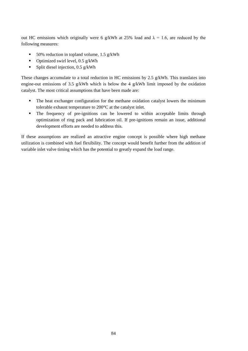
84
out HC emissions which originally were 6 g/kWh at 25% load and λ = 1.6, are reduced by the
following measures:
50% reduction in topland volume, 1.5 g/kWh
Optimized swirl level, 0.5 g/kWh
Split diesel injection, 0.5 g/kWh
These changes accumulate to a total reduction in HC emissions by 2.5 g/kWh. This translates into
engine-out emissions of 3.5 g/kWh which is below the 4 g/kWh limit imposed by the oxidation
catalyst. The most critical assumptions that have been made are:
The heat exchanger configuration for the methane oxidation catalyst lowers the minimum
tolerable exhaust temperature to 200°C at the catalyst inlet.
The frequency of pre-ignitions can be lowered to within acceptable limits through
optimization of ring pack and lubrication oil. If pre-ignitions remain an issue, additional
development efforts are needed to address this.
If these assumptions are realized an attractive engine concept is possible where high methane
utilization is combined with fuel flexibility. The concept would benefit further from the addition of
variable inlet valve timing which has the potential to greatly expand the load range.
85
8 Summary & Conclusions
This thesis summarizes a four year project executed by AVL, KTH and Scania and supported
financially by the Swedish Energy Agency. The main findings and conclusions are organized based
on the three topics that constitute the principal challenges: HC emissions, thermal issues and pre-
ignitions:
HC emissions:
▫ The topland crevice is the largest contributor to the HC emissions, and efforts must be
taken to reduce this volume in order to meet current emissions legislation. The topland
crevice contributes between 50-70% of HC emissions at operating conditions relevant
to lean burn gas engines. Swirl can be used to improve oxidation of HC returning from
crevices, and the optimal swirl number for this purpose was found to be approximately
3. This can reduce HC emissions by approximately 20% compared to quiescent
operation. At λ > 1.8, quenching becomes the main source of HC emissions.
▫ Split pilot injection provides 10-20% emissions reduction without any drawbacks and
should be used at light load if the hardware permits.
▫ RCCI extends the lean limit greatly with maintained combustion efficiency, but is very
challenging from a controls perspective, and is for this reason not considered viable in
the short term. The feasibility of successful methane aftertreatment at the high λ and
corresponding low exhaust temperatures associated with this combustion mode is also
doubtful.
▫ Air motion affects the flame propagation speed through the CH4-air mixture both
directly and indirectly through the effect it has on distribution of the diesel pilot. The
effect is seen as a function of swirl; dual fuel combustion is insensitive to tumble.
Thermal issues:
▫ The rate of injector nozzle hole coking in DDF mode can be several times higher than
during diesel operation. A maximum flow loss of 18% after 3.5 hours of DF operation
at medium load was recorded. The highest rate of nozzle coking occurred at the lowest
injection pressure. This shows that too low injection pressure can be critical in DDF
operation since the decreased shear forces and cavitation in the nozzle holes limit the
deposit removal process. Decreasing the thermal resistance between the injector tip and
the cooling water by inserting a copper sleeve around the injector tip has the potential
to greatly reduce the injector tip temperature and is assumed to be beneficial in
reducing coking.
Pre-ignitions:
▫ Pre-ignitions, rather than knock, limit the load. This holds for fuels with methane
number in the range of 70-100. EGR is the most effective countermeasure to pre-
ignitions.
▫ The temperature required for hot spot ignition is shown to be approximately 1000°C.
This result in combination with the lack of influence seen as the exhaust valves were

86
replaced with sodium cooled valves, makes hot spot ignition an unlikely root cause for
the pre-ignition issues.
▫ Influence of lubrication oil quality on pre-ignition frequency is seen. However, this
effect is insufficient to solve the issue by itself. Further work is required. Oil ignition is
currently the most probable root cause, but other phenomena such as DI injector
dribble cannot be ruled out.
The results from the project are, in chapter 0, summarized into recommendations for the
development of a Euro 6 compliant dual fuel engine. Two key challenges must be addressed for
this development to succeed: an aftertreatment system which allows for low exhaust
temperatures must be available, and the root cause of pre-ignitions should be determined and
suitable countermeasures found.
87
9 References
1. John B. Heywood, Internal Combustion Engine Fundamentals. New York: McGraw-Hill Book
Company, 1988.
2. EIA. (2014, April) U.S. Energy Information Administration, International Energy Statistics.
[Online]. http://www.eia.gov/countries/data.cfm
3. R. Edwards, J-F Larivé, V. Mahieu, and P. Rouveirolles, "Well-to-Wheels analysis of future
automotive fuels and powertrains in the European context," 2007.
4. Kemira, "Presentation Material", 2008.
5. Christian Schwarz and Gunther P. Merker, Combustion Engines Development. Berlin:
Springer-Verlag Berlin, Heidelberg GmbH & Co., 2010.
6. B. S. Brown, C. A. Laforet, S. N. Rogak, and S. R. Munsch, "Comparison of injectors for
compression ignition of natural gas with entrained diesel", International Journal of Engine
Research, vol. 12, 2011.
7. G. A. Karim, Z. Liu, and W. Jones, "Exhaust Emissions from Dual Fuel Engines at Light
Load", SAE 932822, 1993.
8. U. Azimov, E. Tomita, N. Kawahara, and Y. Harada, "Premixed mixture ignition in the end-
gas region (PREMIER) combustion in a natural gas dual-fuel engine: operating range and
exhaust emissions", International Journal of Engine Research, vol. 12, no. 5, 2011.
9. E. Tomita, N. Fukatani, N. Kawahara, K. Maruyama, and T. Komoda, "Combustion
Characteristics and Performance of Supercharged Pyrolysis Gas Engine with Micro-Pilot
Ignition", Vienna, CIMAC 178, 2007.
10. Zdzislaw Stelmasiak, "The Impact of Gas-Air Composition on Combustion Parameters of Dual
Fuel Engines Fed CNG", SAE 2001-01-2235, 2002.
11. Nafis Ahmad-I, M. K. Gajendra Babu, and A. Ramesh, "Experimental Investigations of
Different Parameters Affecting the Performance of a CNG-Diesel Dual Fuel Engine", SAE
2005-01-3767, 2005.
12. Mohamed Y.E. Selim, "Effect of engine parameters and gaseous fuel type on the cyclic
variability of dual fuel engines", Fuel, vol. 84, 2004.
13. Jie Shen, Jun Qin, and Mingfa Yao, "Turbocharged diesel/CNG Dual-Fuel Engines with
Intercooler: Combustion, Emissions and Performance", SAE 2003-01-3082, 2003.
14. V. Balasubramanian, K. Sridhara, and V. Ganesan, "Performance Evaluation of a Small
Agricultural Engine Operated on Dual Fuel (Diesel + Natural Gas) System", SAE 951777,
88
1995.
15. Phan Minh Duc and Kanit Wattanavichien, "Study on biogas premixed charge diesel dual
fuelled engine", Energy Conversion & Management, vol. 48, 2007.
16. Seung Hyun Yoon and Chang Sik Lee, "Experimental investigation on the combustion and
exhaust emission characteristics of biogas-diesel dual-fuel combustion in a CI engine", Fuel
Processing Technology, vol. 92, 2011.
17. G. A. Karim, "Combustion in Gas Fueled Compression: Ignition Engines of the Dual Fuel
Type", ASME, Journal of Engineering for Gas Turbines and Power, vol. 125, 2003.
18. Ghazi A. Karim, "A Review of the Combustion Process in the Dual Fuel Engine - the Gas
Diesel Engine", Prog. Energy Combust. Sci., vol. 6, 1980.
19. Antonio Paolo Carlucci, Domenico Laforgia, Roberto Saracino, and Giuseppe Toto, "Study
of Combustion Development in Methane-Diesel Dual Fuel Engines, Based on the Analysis of
In-Cylinder Luminance", SAE 2010-01-1297, 2010.
20. Antonio P. Carlucci, Domenico Laforgia, Roberto Saracino, and Giuseppe Toto,
"Combustion and emissions control in a diesel-methane dual fuel engines: The effects of
methane supply method combined with variable in-cylinder bulk motion", Energy Conversion
and Management, vol. 52, 2011.
21. Z. Liu and G. A. Karim, "A Predictive Model for the Combustion Process in Dual Fuel
Engines", SAE 952435, 1995.
22. Nafis Ahmad-I, M. K. Gajendra Babu, and A. Ramesh, "Investigations on Combustion and
Performance Characteristics of a Turbocharged Natural Gas and Pilot Ignition Dual Fuel
Engine", SAE 2005-01-3775, 2005.
23. D. T. Hountalas and R. G. Papagiannakis, "Development of a Simulation Model for Direct
Injection Dual Fuel Diesel-Natural Gas Engines", SAE 2000-01-0286, 2000.
24. D. T. Hountalas and R. G. Papagiannakis, "Theoretical and Experimental Investigation of a
Direct Injection Dual Fuel Diesel-Natural Gas Engine", SAE 2002-01-0868, 2002.
25. R. G. Papagiannakis, D. T. Hountalas, and P. N. Kotsiopoulos, "Experimental and
Theoretical Analysis of the Combustion and Pollutants Formation Mechanisms in Dual Fuel DI
Diesel Engines", SAE 2005-01-1726, 2005.
26. Jin Kusaka, Norifumi Mizushima, Yasuhiro Daisho, and Takeshi Saito, "A Numerical
Study on Combustion and Exhaust Gas Emissions of a Dual Fuel Natural Gas Engine Using a
Multi-Dimensional Model Combined with Detailed Kinetics", SAE 2003-01-1939, 2003.
89
27. Jin Kusaka, Ko-ichiro Tsuzuki, Yasuhiro Daisho, and Takeshi Saito, "A Numerical Study
on Combustion and Exhaust Gas Emissions Characteristics of a Dual Fuel Natural Gas Engine
Using a Multi-Dimensional Model Combined With Detailed Kinetics", SAE 2002-01-1750,
2002.
28. Youtong Zhang, Song-Charng Kong, and Rolf D. Reitz, "Modeling and Simulation of a Dual
Fuel (Diesel/Natural Gas) Engine With Multidimensional CFD", SAE 2003-01-0755, 2003.
29. Satbir Singh, Song-Charng Kong, Rolf D. Reitz, Sundar R. Krishnan, and K. Clark
Midkiff, "Modeling and Experiments of Dual-Fuel Engine Combustion and Emissions", SAE
2004-01-0092, 2004.
30. Zhentao Liu and Shaomei Fei, "Emissions Prediction of CNG/Diesel Dual Fuel Engine Based
on RBF Neural Network", SAE 2004-01-0646, 2004.
31. M. H. Saidi, K. Isazadeh Far, and V. Pirouzpanah, "Analysis of Combustion Process in Dual
Fuel Diesel Engines: Knock Phenomenon Approach", SAE 2005-01-1132, 2005.
32. Eiji Tomita, Nobuyuki Kawahara, Zhenyu Piao, and Ryoichi Yamaguchi, "Effects of EGR
and Early Injection of Diesel Fuel on Combustion Characteristics and Exhaust Emissions in a
Methane Dual Fuel Engine", SAE 2002-01-2723, 2002.
33. Y. Qi, S. R. Krishnan, H. Yang, and H. C. Midkiff, "Effect of hot exhaust gas recirculation
on the performance and emissions of an advanced injection low pilot-injected natural gas
engine", Int. J. Engine Res., vol. 8, 2006.
34. Masahiro Shioji, Takuji Ishiyama, Makoto Ikegami, Shinichi Mitani, and Hiroaki Shibata,
"Performance and Exhaust Emissions in a Natural-Gas Fueled Dual-Fuel Engine", JSME
International Journal, vol. 44, no. 4, 2001.
35. B. B. Sahoo, N. Sahoo, and U. K. Saha, "Effect of engine parameters and type of gaseous fuel
on the performance of dual-fuel gas diesel engines-A critical review", Renewable and
Sustainable Energy Reviews, vol. 13, 2009.
36. G. H. Abd Alla, H. A. Soliman, O. A. Badr, and M. F. Abd Rabbo, "Effect of injection
timing on the performance of a dual fuel engine", Energy Conversion and Management, vol. 43,
2002.
37. Z. Lin and W. Su, "A Study On The Determination of the Amount of Pilot Injection and Rich
and Lean Boundaries of the Pre-Mixed CNG/Air Mixture For a CNG/Diesel Dual-Fuel Engine",
SAE 2003-01-0765, 2003.
38. Inge Saanum, Marie Bysveen, Per Tunestål, and Bengt Johansson, "Lean Burn Versus
Stoichiometric Operation with EGR and 3-Way Catalyst of an Engine Fueled with Natural Gas
90
and Hydrogen Enriched Natural Gas", SAE 2007-01-0015, 2007.
39. Manfred Amann, Terrence Alger, and Darius Mehta, "The Effect of EGR on Low-Speed
Pre-Ignition in Boosted SI Engines", SAE 2011-01-0339, 2011.
40. R. G. Papagiannakis, C. D. Rakopoulos, D. T. Hountalas, and D. C. Rakoupolos, "Emission
characteristics of high speed, dual fuel, compression ignition engine operating in wide range of
natural gas/diesel fuel proportions", Fuel, vol. 89, 2010.
41. Kyoungdoug Min, Wai K. Cheng, and John B. Heywood, "The Effects of Crevices on the
Engine-Out Hydrocarbon Emissions in SI Engines", SAE 940306, 1994.
42. Thananchai Tepimonrat, Kittisak Kamsinla, Ekathai Wirojsakunchai, Tanet
Aroonsrisopon, and Krisada Wannatong, "Use of Exhaust Valve Timing Advance for High
Natural Gas Utilization in Low-Load Diesel Dual Fuel Operation", SAE 2011-01-1767, 2011.
43. R. Backman, "Open Source Rapid Prototyping Environment", SAE 2011-01-0711, 2011.
44. Tunestål, "Self-tuning gross heat release computation for internal combustion engines.",
Control Engineering Practice, vol. 17, 2009.
45. Thien G., "Entwicklungsarbeiten an Ventilkanälen von Viertakt-Dieselmotoren", ÖIZ, vol. 9,
1965.
46. Morel, T.; Rackmil, I.; Keribar, R.; Jennings, M. J., "Model for Heat Transfer and
Combustion in Spark Ignited Engines and Its Comparison with Experiments", SAE 880198,
1988.
47. Uzkan, Teoman; Borgnakke, Claus; Morel, Thomas, "Characterization of Flow Produced by
High-Swirl Inlet Port", SAE 830266, 1983.
48. Morel, Thomas; Keribar, Rifat, "A Model for Predicting Spatially and Time Resolved
Convective Heat Transfer in Bowl-in-Piston Combustion Chambers", SAE 850204, 1985.
49. Henrik W. R. Dembinski and Hans-Erik Ångström, "An Experimental Study of the
Influence of Variable In-Cylinder Flow, Caused by Active Valve Train, on Combustion and
Emissions in a Diesel Engine at Low Lambda Operation", SAE 2011-01-1830, 2011.
50. Kyoungdoug Min, The Effects of Crevices on the Engine-out Hydrocarbon Emissions in Spark
Ignition Engines. USA: Massachusetts Institute of Technology, 1994.
51. Harry C. Watson and Jeremy Lawrence, "Instantaneous Multi-Point Versus Single-Point
Measurement of Exhaust Port Hydrocarbons of Ultra Lean Mixture", SAE 2000-01-0241, 2000.
52. David Kayes and Simone Hochgreb, "Time, Space and Species Resolved Measurements of
Engine-Out Hydrocarbon Emissions from Spark-Ignited Engines", Taylor & Francis,
91
Combustion Science and Technology, vol. 127, no. 1-6, pp. 333-362, Apr 1997.
53. I C Finlay, D J Boam, J F Bingham, and T A Clark, "Fast Response FID Measurement of
Unburned Hydrocarbons in the Exhaust Port of a Firing Gasoline Engine", SAE 902165, 1990.
54. David Kayes and Simone Hochgreb, "Development of a Time and Space Resolved Sampling
Probe Diagnostic for Engine Exhaust Hydrocarbons", SAE 961002, 1996.
55. Neil D. Thompson and James S. Wallace, "Effect of Engine Operating Variables and Piston
and Ring Parameters on Crevice Hydrocarbon Emissions", SAE 940480, 1994.
56. T K Jensen, J Schramm, K Narusawa, and S Hori, "Analysis of UHC Emission from a
Natural Gas SI Engine Using Fast Response FID and a Heat Release Model", SAE 2001-01-
3533, 2001.
57. Craig D Marriott, SongCharng Kong, and Rolf D Reitz, "Investigation of Hydrocarbon
Emissions from a Direct Injection-Gasoline Premixed Charge Compression Ignited Engine",
SAE 2002-01-0419, 2002.
58. Rodney J Tabaczynski, John B Heywood, and James C Keck, "Time-Resolved
Measurements of Hydrocarbon Mass Flowrate in the Exhaust of a Spark-Ignition Engine", SAE
720112, 1972.
59. Giorgio Tondelli, Massimo Carriero, and Arcangelo Pedicillo, "Combustion Chamber
Deposits: Fuel and Lubricant Effects on Exhaust Hydrocarbon Emissions Measured by Fast FID
Analyzer", SAE 2000-01-2024, 2000.
60. V M Salazar and J B Ghandhi, "Liquid Fuel Effects on the Unburned Hydrocarbon Emissions
of a Small Engine", SAE 2006-32-0033, 2006.
61. L de Francqueville, B Thirouard, and J Cherel, "Investigating Unburned Hydrocarbon(UHC)
Emissions in a GDI Engine(Homogenous and Stratified Modes) Using Formaldehyde LIF and
Fast-FID MEasurements in the Exhaust Port", SAE 2007-01-4029, 2007.
62. Alexander Guliaeff, Klaus Wanninger, Frank Klose, Gerd Maletz, and Arno Tissler,
"Development of a Sulfur Tolerant PGM Based Zeolite Catalyst for Methane Oxidation and
Low Temperature Hydrocarbon Trapping", SAE 2013-01-0531, 2013.
63. A. C. Alkidas, R. J. Drews, and W. F. Miller, "Effects of Piston Crevice Geometry on the
Steady-State Engine-Out Hydrocarbon Emissions of a S.I. Engine", SAE 952537, 1995.
64. Masayuki Tamura, Teruhiro Sakurai, and Hideo Tai, "A Study of Crevice Flow in a Gas
Engine using Laser-induced Fluorescence", SAE 2001-01-0913, 2001.
65. Mitsuro Konno and Zhili Chen, "Ignition Mechanisms of HCCI Combustion Process Fueled
92
with Methane/DME Composite Fuel", SAE 2005-01-0182, 2005.
66. Jennifer Wheeler et al., "Increasing EGR Tolerance Using High Tumble in a Modern GTDI
Engine for Improved Low-Speed Performance", SAE 2013-01-1123, 2013.
67. Amer Ahmad Amer and Thirumala N. Reddy, "Multidimensional Optimization of In-
Cylinder Tumble Motion for the New Chrysler Hemi", SAE 2002-01-1732, 2002.
68. Michael J. Bergin et al., "Fuel Injection and Mean Swirl Effects on Combustion and Soot
Formation in Heavy Duty Diesel Engines", SAE 2007-01-0912, 2007.
69. Henrik Dembinski and Hans-Erik Angstrom, "Swirl and Injection Pressure Impact on After-
Oxidation in Diesel Combustion, Examined with Simultaneous Combustion Image Velocimetry
and Two Colour Optical Method", SAE 2013-01-0913, 2013.
70. Antila, Eero; Imperato, Matteo; Kaario, Ossi; Larmi, Martti, "Effect on Intake Channel
Design to Cylinder Charge and Initial Swirl", SAE 2010-01-0624, 2010.
71. A. Birgel et al., "Deposit Formation in the Holes of Diesel Injector Nozzles: A Critical
Review", SAE 2008-01-2383, 2008.
72. B. Argueyrolles et al., "Influence of Injector Nozzle Design and Cavitation on Coking
Phenomenon", SAE 2007-01-1896, 2007.
73. O. Kazuhiro, K. Nakai, R. Ueda, N. Kakehashi, K. Sunami M. Ikemoto, "Injection Nozzle
Coking Mechanism in Common-rail Diesel Engine", SAE 2011-01-1818, 2011.
74. P. Risberg et al., "Development of a Heavy Duty Nozzle Coking Test", SAE 2013-01-2674,
2013.
75. A. Birgel et al., "Investigation on Deposit Formation in the Holes of Diesel Injector Nozzles",
SAE 2011-01-1924, 2011.
76. J. Tang et al., "Coking Phenomena in Nozzle Orifices of DI-Diesel Engines", SAE 2009-01-
0837, 2009.
77. R. H. Barbour, D. Arters, J. Dietz, M. Macduff, and R. Quigley, "Diesel Detergent Additive
Responses in Modern, High-speed, Direct-Injection, Light-Duty Engines", SAE 2007-01-2001,
2007.
78. A. J. Velaers, S. de Goede, C. Woolard, and R. Burnham, "Injector Fouling Performance and
Solubility of GTL Diesel Dosed with Zinc", SAE 2013-01-1697, 2013.
79. J. C. Livengood and P. C. Wu, "Correlation of autoignition phenomena in internal combustion
engines and rapid compression machines", Symposium (International) on Combustion, vol. 5,
93
no. 1, pp. 347 - 356, 1955.
80. Gautam T. Kalghatgi and Derek Bradley, "Pre-ignition and 'super-knock' in turbo-charged
spark-ignition engines", SAGE, International Journal of Engine Research, vol. 13, no. 4, pp.
399-414, February 2012.
81. Akram Zahdeh et al., "Fundamental Approach to Investigate Pre-Ignition in Boosted SI
Engines", SAE 2011-01-0340, 2011.
82. K. Takeuchi, K. Fujimoto, S. Hirano, and M. Yamashita, "Investigation of Engine Oil Effect
on Abnormal Combustion in Turbocharged Direct Injection - Spark Ignition Engines", SAE Int.
J. Fuels Lubr, vol. 5, no. 3, 2012.
83. Shinji Yasueda, "The investigation of the unstable combustion caused by the autoignition of
lubricating oil in premixed gas engine"in Dessauer Gasmotoren-Konferenz, Dessau-Roßlau,
2013.
84. B. Liu, M. D. Checkel, R.E. Hayes, M. Zheng, and E. Mirosh, "Experimental and Modelling
Study of Variable Cycle Time for a Reversing Flow Catalytic Converter for Natural Gas/Diesel
Dual Fuel Engines", SAE 2000-01-0213, 2000.
94
10 Definitions/Abbreviations
1D One-dimensional
AFR Air to fuel ratio
AFRdiesel Stoichiometric air to fuel ratio for diesel
AFRmethane Stoichiometric air to fuel ratio for methane
ATDC After combustion top dead center
AVT Active valve train
BMEP Brake mean effective pressure
BSCO Brake specific emissions of carbon monoxide
BSHC Brake specific hydrocarbon emissions
BSNOX Brake specific emissions of nitrogen oxides
BTDC Before combustion top dead center
CA Crank angle with reference to combustion TDC
CA50 Crank angle of 50% heat release
CFD Computational fluid dynamics
CI Compression ignited
CNG Compressed natural gas
CO Carbon monoxide
CO2 Carbon dioxide
CoV Coefficient of variation of IMEP
DDF Diesel dual fuel
DI Direct injection
DME Dimethyl ether
DPF Diesel particulate filter
ECM Engine control module
EDX Energy dispersive X-ray spectroscopy
EGR Exhaust gas recirculation
EPA Environmental protection agency
EVC Exhaust valve closing
EVO Exhaust valve opening
FID Flame ionization detector
FT Fischer-Tropsch
GHG Greenhouse gas
GUI Graphical user interface
HC Hydrocarbon
HCCI Homogenous charge compression ignition
HD Heavy duty
IMEP Indicated mean effective pressure
IVC Intake valve closing
IVO Intake valve opening
LSPI Low speed pre-ignition
MBT Combustion phasing of maximum brake torque
MN Methane number
NG Natural gas
NOx Oxides of nitrogen; nitric oxide and nitrogen dioxide
OP Operating point
PPCI Partially premixed compression ignition
95
ppm Parts per million
PWM Pulse width modulation
RCCI Fuel reactivity controlled compression ignition
RME Rapeseed-oil methyl ester
ROHR Rate of heat release
RPM Revolutions per minute
SACI Spark assisted compression ignition
SCR Selective catalytic reduction
SEM Scanning electron microscope
SI Spark ignited
SN Swirl number
SOC Start of combustion
SOE Start of energizing of injector coil
STD Standard
TDC Top dead center
TN Tumble number
TPZ Trapezoid
WTW Well to wheel
λ Air excess ratio
96
11 Summary of publications/Contributions
Six papers are appended. Unless noted otherwise, the writing of the publications along with all
measurements, simulations and evaluation of data were performed by the author of this thesis,
Fredrik Königsson, and reviewed by Professor Hans-Erik Ångström. Per Stålhammar contributed to
the planning of the investigations in the cases where he is listed. All conference papers have been
presented by Fredrik Königsson.
Paper I: Combustion Modes in a Diesel-CNG Dual Fuel Engine. Fredrik Königsson, Per
Stålhammar and Hans-Erik Ångström.
SAE Technical Paper 2011-01-1962, presented at the 2011 JSAE Powertrains, Fuels & Lubes
Conference in Kyoto, Japan
This paper characterizes the unconventional combustion modes available in the port injected Diesel
Dual Fuel, DDF, engine; PPCI and HCCI/RCCI. They are compared to diesel and conventional
DDF operation with respect to emissions and efficiency. Very little work was previously presented
on the topic of diesel-methane HCCI/RCCI. To the author‟s knowledge, the application of a late
pilot injection to trigger the combustion, in combination with an early diesel injection which
conditions the bulk gas and enables PPCI combustion, is new. The comparison between PPCI,
RCCI, DDF combustion and diesel operation is novel.
Paper II: Characterization and Potential of Dual Fuel Combustion in a Modern Diesel
Engine. Fredrik Königsson, Per Stålhammar and Hans-Erik Ångström.
SAE Technical Paper 2011-01-2223, presented at the 2011 SAE Commercial Vehicle Engineering
Congress in Chicago, USA
The objective of this paper was to characterize and investigate the potential for DDF combustion,
utilizing all degrees of freedom available in a modern diesel engine. The paper discusses the effects
of different parameters: combustion phasing, inlet temperature, EGR and diesel substitution rate.
The main contribution from this paper is the presentation of the parameter variations in a clear and
consistent way which has previously been lacking. The paper‟s focus on the effect of each
parameter on the tolerance for lean operation is new.
Paper III: Controlling the Injector Tip Temperature in a Diesel Dual Fuel Engine. Fredrik
Königsson, Per Stålhammar and Hans-Erik Ångström.
SAE Technical Paper 2012-01-0826, presented at the 2012 SAE World Congress in Detroit, USA
This paper investigated the factors causing high injector tip temperatures in a DDF engine and the
underlying mechanisms which transfer heat to and from the injector tip. Parameter sweeps of each
influential parameter were carried out and evaluated. In addition to this, a simple and useful model
was constructed based on the heat balance of the injector tip. No previous work addresses the issue
of nozzle tip temperatures in DDF engines. The entire content of the paper is therefore new.
Paper IV: The Influence of Crevices on Hydrocarbon Emissions from a Diesel-Methane Dual
Fuel Engine. Fredrik Königsson, Johannes Kuyper, Per Stålhammar and Hans-Erik
Ångström.
SAE Technical Paper 2013-01-0848, presented at the 2013 SAE World Congress in Detroit, USA
97
This paper investigates how the sources of hydrocarbon emissions vary as engine operating
conditions change. Five pistons with known increases to the topland volume were manufactured.
For each of these pistons, parameter sweeps were carried out. Extrapolation of the data to a
hypothetical topland volume of zero enabled the breakdown of hydrocarbon emissions into two
parts; one part which originates from the topland crevice and one part which originates from other
sources. The measurements presented in this publication were carried out by a Master‟s student,
Johannes Kuyper, under the supervision of the present author, Fredrik Königsson, who also
performed the evaluation of the data and the writing of the publication. Previous work exists which
investigates the sources of HC emissions for SI engines, mainly for gasoline fuel and stoichiometric
operation. The breakdown of HC emissions into different categories for the combination of lean
operation and CNG has not been previously shown. Additionally, the effect of parameter settings on
the contributions to total HC emissions from quenching and crevices is new.
Paper V: The Influence of In-Cylinder Flows on Emissions and Heat Transfer from Methane-
Diesel Dual Fuel. Fredrik Königsson, Henrik Dembinski and Hans-Erik Ångström.
SAE Technical Paper 2013-01-2509, presented at the 2013 SAE Powertrains, Fuels & Lubes
conference in Seoul, S. Korea
A fully variable valve train was used in combination with a high-swirl cylinder head to create
different in-cylinder air flows. The effect of these air flows, swirl and tumble, on dual fuel
combustion at high λ was investigated with regards to combustion, emissions and heat transfer. The
measurements in the steady-state flow rig were carried out at Scania CV under the supervision of
the co-author of the publication, Henrik Dembinski who also contributed with the GT-power
simulations and supported the experimental work. Some of the measurements during this
investigation were carried out by a Master‟s student, Hans-Christian Nilsson-Vinnars under the
supervision of the present author. Most of the measurements presented in the publication and in this
thesis were carried out by the present author, Fredrik Königsson, along with the evaluation of the
data and the writing of the publication. The combination of a fully variable valve train with DDF
combustion has not been subject to prior investigations. The behavior of DDF combustion over a
comprehensive swirl-tumble-range has, for this reason, not been previously documented. The new
findings include the observation that swirl increases the oxidation of HC returning from crevices
and that DDF combustion is insensitive to tumble.
Paper VI: Nozzle Coking in CNG-Diesel Dual Fuel Engines. Fredrik Königsson, Per Risberg,
Hans-Erik Ångström.
SAE Technical Paper 2014-01-2700, presented at the 2014 SAE Powertrains, Fuels & Lubes
conference in Birmingham, Great Britain.
The paper investigates injector nozzle coking during dual fuel operation as a function of different
parameter settings and at different nozzle tip temperatures. Diesel fuel contaminated by zinc
neodecanoate was used during the tests and nozzle flow rate was measured in a steady state test
bench before and after the engine tests were performed. The single cylinder measurements were
performed by two Master‟s students, Martin Thyrestam and Marcus Svensson, under the
supervision of Per Risberg. The publication was written in collaboration with Per Risberg who
contributed to an equal degree as the present author, Fredrik Königsson, to the evaluation of the
data and the writing of the paper. Since no prior publications have been found which addresses the

98
topic of injector nozzle coking during dual fuel operation, the entire content of the publication is
new.


![Detailed Kinetic Mechanism of CNG Combustion in …nisms of methane in IC engine and predicted the com-bustion temperature and pressure in the combustion chamber of the IC engine [27]](https://img.pdfslide.net/doc/110x75/5ea9f03f39dfe221a1737d63/detailed-kinetic-mechanism-of-cng-combustion-in-nisms-of-methane-in-ic-engine-and.jpg)