Embed Size (px)
Citation preview
baL
Dl
2
3
On-line monitoring of one-step laser fabrication ofmicro-optical components
J. Enrique Julia and Juan Carlos Soriano
The use of an on-line monitoring method based on photoelasticity techniques for the fabrication ofmicro-optical components by means of controlled laser heating is described. From this description it ispossible to show in real time the mechanical stresses that form the microelement. A new parameter,stressed area, is introduced that quantifies the stresses of a microelement during its fabrication, facili-tating a deeper understanding of the physical phenomena involved in the process as well as being a usefultest of quality. It also permits the stress produced in the manufacturing process and the opticalproperties of the final microelement to be correlated. The results for several microlenses monitored withthis technique are presented. © 2001 Optical Society of America
OCIS codes: 350.3950, 220.4840, 220.4000.
1. Introduction
Nowadays there are several methods for the produc-tion of micro-optical components ~MOCs! that areased on conventional techniques.1 Some of themre based on lithographic methods similar to theithographie Galvanik Abformung process.2 Others
use appropriate geometrical changes to combine alithographic process with a heat source.3–5 Non-lithographic techniques consist of engraving the ma-terial directly with a laser.6,7 All these methodsallow us to obtain high-quality microelements.8,9
Moreover, micro-optics is an active field, and newfabrication methods are continually arising.10,11
Unfortunately, currently used methods have somedisadvantages, such as high cost, length of time con-sumed by the process, air pollution abatement re-quirements, and the fact that the microelementobtained is not always transparent in the visiblerange. In the last-named case, postprocessing isnecessary. The most popular postprocessing tech-nique is the making of a metallic mold by electroform-ing; in this case the MOCs are produced by plasticinjection.
An alternative technique that partially solves
J. E. Julia and J. C. Soriano [email protected]! are with theepartamento de Optica, Universidad de Valencia, Doctor Mo-
iner, 50, 46100-Burjassot, Valencia, Spain.Received 17 July 2000; revised manuscript received 6 March
001.0003-6935y01y193220-05$15.00y0© 2001 Optical Society of America
220 APPLIED OPTICS y Vol. 40, No. 19 y 1 July 2001
these problems is the one-step fabrication process.It is based on local heating by a laser, either by directfocusing over an optical glass12–14 or by formation ofthe image of a small diaphragm over a polymer.15
During the formation process, the temperature of theirradiated zone increases until it reaches the meltingpoint of the material. In the center of the irradiatedzone, the surface tension acts on the melted materialand deforms the surface spherically, as the temper-ature is high enough that viscosity can be neglected.Besides, in the external zone the temperature is notso high as in the center, estimated as three timeslesser than the melting point, so the viscosity, whichis relevant in this case, imparts an aspheric shape tothe surface of the external zone.13 If the irradiationtime ~t! is long enough, the action of gravity forms adiverging microlens or micromirror.
From the point of view of stress formation, elastic,relaxation, and residual stresses are present in theformation of MOCs. Elastic stress is produced bythe thermal field applied by the laser, and relaxationstress is due to both viscous flow and cooling. Theresidual stress is a result of the other kinds of stress,and the shorter the cooling stage, the greater theresidual stress. As a result, the surface profile ischanged after laser irradiation.12
The advantages of the new technique are that theMOCs obtained are directly applicable in the visiblerange, the cost of equipment and materials is low,and the fabrication process is fast and nonpolluting.Furthermore, with this technique it is possible todesign the geometry, size, and other properties of anarray of MOCs in a simple way. Its main drawbacks
ltrf
i
do
rMpTMb
opptn
IfiTlITbriap
1tBh
may be that, because it is in a preliminary stage ofdevelopment, the quality of the microelements ob-tained to date has not been so high as with earliermethods and that the range of diameter and focallength is limited.13 This technique is not appliedonly to the fabrication of MOCs; another applicationis in the production of hard disks in the electronicsindustry.16
Monitoring systems are widely used in fabricationprocesses to mach the characteristics of the productwhen it is at a particular step of manufacture withthe expected characteristics. Three main types ofmonitoring are considered: in-line, on-line, and out-line. For the studies reported in the references inthis paper, out-line monitoring by means of geomet-rical or interferometric methods was used. We havefound no reports of in-line ~i.e., self-controlled! or on-ine ~controlled! monitoring systems. The techniquehat we present here is for useful obtaining geomet-ical parameters of lenses related to their optical per-ormance.
In this paper we report our development of a mon-toring method17 to improve the quality of laser
MOCs and control their optical properties. It isbased on examination of the mechanical stresses thatappear during the MOC formation. The manufac-ture of laser MOCs can be analyzed in terms of theoccurrence and development of stresses.12 Based onthese analyses, understanding the physical mecha-nisms of manufacturing will be easier. In the sameway, it will be possible to study the effects of theprocessing parameters irradiance and t ~irradiationtime! in the creation of a MOC. To this end weintroduce a new parameter, the stressed area ~SA!,
efined below, which is directly connected with theptical properties of the MOC.This monitoring method may pave the way to a
eal-time quality test with which the dynamics ofOC formation can be compared with a previous
attern of a MOC with well-known optical properties.his fact is important in the production of arrays ofOCs because it is possible to verify the resemblance
etween discrete elements.In Section 2 we show the basic requirements of the
n-line monitoring method. In Section 3 the stressattern obtained as well as the definition of the SAarameter are described and the connection of SA tohe optical properties of the MOC are explained. Fi-ally, in Section 5 we state some conclusions.
2. Monitoring System
Our monitoring method is based on photoelasticitytechniques. With these techniques it is possible, ina simple way, to show the birefrigence induced in asample.18 Therefore it is possible to display the me-chanical stresses produced by the thermal field dur-ing the fabrication of a MOC. The inducedbirefrigence observed can give us information aboutthe optical properties of the MOC because the geom-etry obtained is related to the mechanical stressesthat are produced by heating. This is possible be-
cause the change produced in the refractive index is,in general, small enough to be neglected.12
The advantages of using a photoelasticity tech-nique rather than an interferometric one are the pos-sibility of producing a low-cost on-line monitoringsystem, because a laser source is not required, andthe simplicity of the experimental setup.
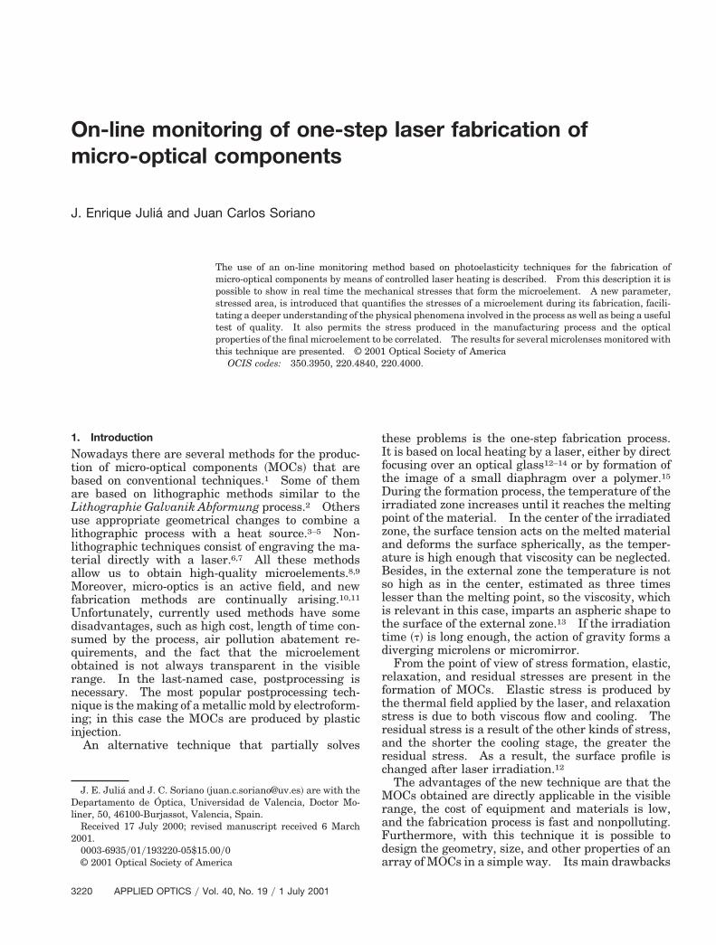
The main characteristics of the on-line monitoringmethod are depicted in Fig. 1. The setup includes awhite-light source with two crossed linear polarizers.The entire process is captured by an 8-bit monochro-matic CCD camera with a 0.8–4.03 zoom objective.n this way it is possible to obtain the optical magni-cation necessary for observing MOC fabrication.he captured scene is MPEG-converted to permit se-
ection of the most interesting shots for later studies.t is possible to obtain 25 JPEG imagesys in this way.he glass sample produces two separate images, sidey each side, but their intensity is quite low. A mir-or is placed under the glass sample to create a thirdmage with higher intensity. The two spurious im-ges created by the sample are neglected in the ex-eriments.
3. Results
This monitoring method was applied to fabrication ofmicrolenses direct focusing of a CO2 laser source ex-cited by a radio frequency. Irradiation time t was–15 s, depending on the properties of the bulk ma-erial. The MOCs were made from Borofloat andK7 glass formed over glass for microscope slides andad an estimated irradiance range of 6.0 3 103–2.5 3
104 Wycm2. The f-number range of the MOCs was1–6.
The focal length of a MOC was measured by directfocusing of a collimated laser beam. The diametersof MOCs were measured with an optical microscopewith directional front lighting as well as by this mon-itoring method, as we explain below.
A. Stress Pattern
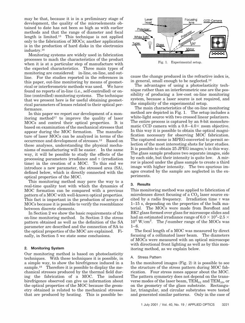
In the monitored images ~Fig. 2! it is possible to seethe structure of the stress pattern during MOC fab-rication. Four stress zones appear about the MOC.The pattern symmetry does not depend on the trans-verse modes of the laser beam, TEM01 and TEM10, oron the geometry of the glass substrate. Rectangu-lar, triangular, and circular substrates were testedand generated similar patterns. Only in the case of
Fig. 1. Experimental setup.
1 July 2001 y Vol. 40, No. 19 y APPLIED OPTICS 3221
2c
ii
3
the triangular sample was one of the orthogonal darkbands, the closest to the hypotenuse of the glass,oriented to this side of the material. Also, the fourstress lobes have nearly the same area, a fact thatillustrates the radial symmetry of the MOCs obtainedand could be a useful test for astigmatism in a MOC.So all the residual stress is located in only four places,and there is no residual stress inside the MOC. Thereasons for this are beyond the scope of this experi-ment. Nevertheless, there has been some study ofbirefrigence patterns that are due to thermal stress-es.19,20
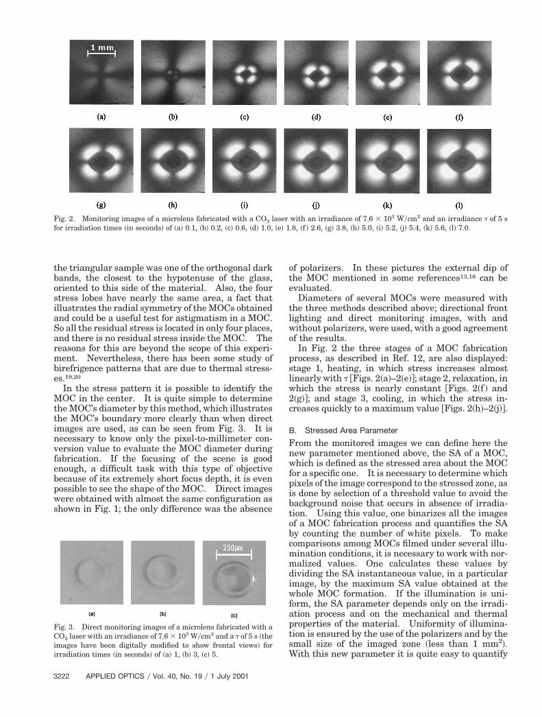
In the stress pattern it is possible to identify theMOC in the center. It is quite simple to determinethe MOC’s diameter by this method, which illustratesthe MOC’s boundary more clearly than when directimages are used, as can be seen from Fig. 3. It isnecessary to know only the pixel-to-millimeter con-version value to evaluate the MOC diameter duringfabrication. If the focusing of the scene is goodenough, a difficult task with this type of objectivebecause of its extremely short focus depth, it is evenpossible to see the shape of the MOC. Direct imageswere obtained with almost the same configuration asshown in Fig. 1; the only difference was the absence
Fig. 2. Monitoring images of a microlens fabricated with a CO2 lfor irradiation times ~in seconds! of ~a! 0.1, ~b! 0.2, ~c! 0.6, ~d! 1.0,
Fig. 3. Direct monitoring images of a microlens fabricated with aCO2 laser with an irradiance of 7.6 3 103 Wycm2 and a t of 5 s ~themages have been digitally modified to show frontal views! forrradiation times ~in seconds! of ~a! 1, ~b! 3, ~c! 5.
222 APPLIED OPTICS y Vol. 40, No. 19 y 1 July 2001
of polarizers. In these pictures the external dip ofthe MOC mentioned in some references13,16 can beevaluated.
Diameters of several MOCs were measured withthe three methods described above; directional frontlighting and direct monitoring images, with andwithout polarizers, were used, with a good agreementof the results.
In Fig. 2 the three stages of a MOC fabricationprocess, as described in Ref. 12, are also displayed:stage 1, heating, in which stress increases almostlinearly with t @Figs. 2~a!–2~e!#; stage 2, relaxation, inwhich the stress is nearly constant @Figs. 2~f ! and~g!#; and stage 3, cooling, in which the stress in-reases quickly to a maximum value @Figs. 2~h!–2~j!#.
B. Stressed Area Parameter
From the monitored images we can define here thenew parameter mentioned above, the SA of a MOC,which is defined as the stressed area about the MOCfor a specific one. It is necessary to determine whichpixels of the image correspond to the stressed zone, asis done by selection of a threshold value to avoid thebackground noise that occurs in absence of irradia-tion. Using this value, one binarizes all the imagesof a MOC fabrication process and quantifies the SAby counting the number of white pixels. To makecomparisons among MOCs filmed under several illu-mination conditions, it is necessary to work with nor-malized values. One calculates these values bydividing the SA instantaneous value, in a particularimage, by the maximum SA value obtained at thewhole MOC formation. If the illumination is uni-form, the SA parameter depends only on the irradi-ation process and on the mechanical and thermalproperties of the material. Uniformity of illumina-tion is ensured by the use of the polarizers and by thesmall size of the imaged zone ~less than 1 mm2!.With this new parameter it is quite easy to quantify
with an irradiance of 7.6 3 103 Wycm2 and an irradiance t of 5 s.8, ~f ! 2.6, ~g! 3.8, ~h! 5.0, ~i! 5.2, ~j! 5.4, ~k! 5.6, ~l! 7.0.
aser~e! 1
urpcfbftNt
wimtDi
s
tdFsk
a property, in this case the stress, to study the fab-rication process.
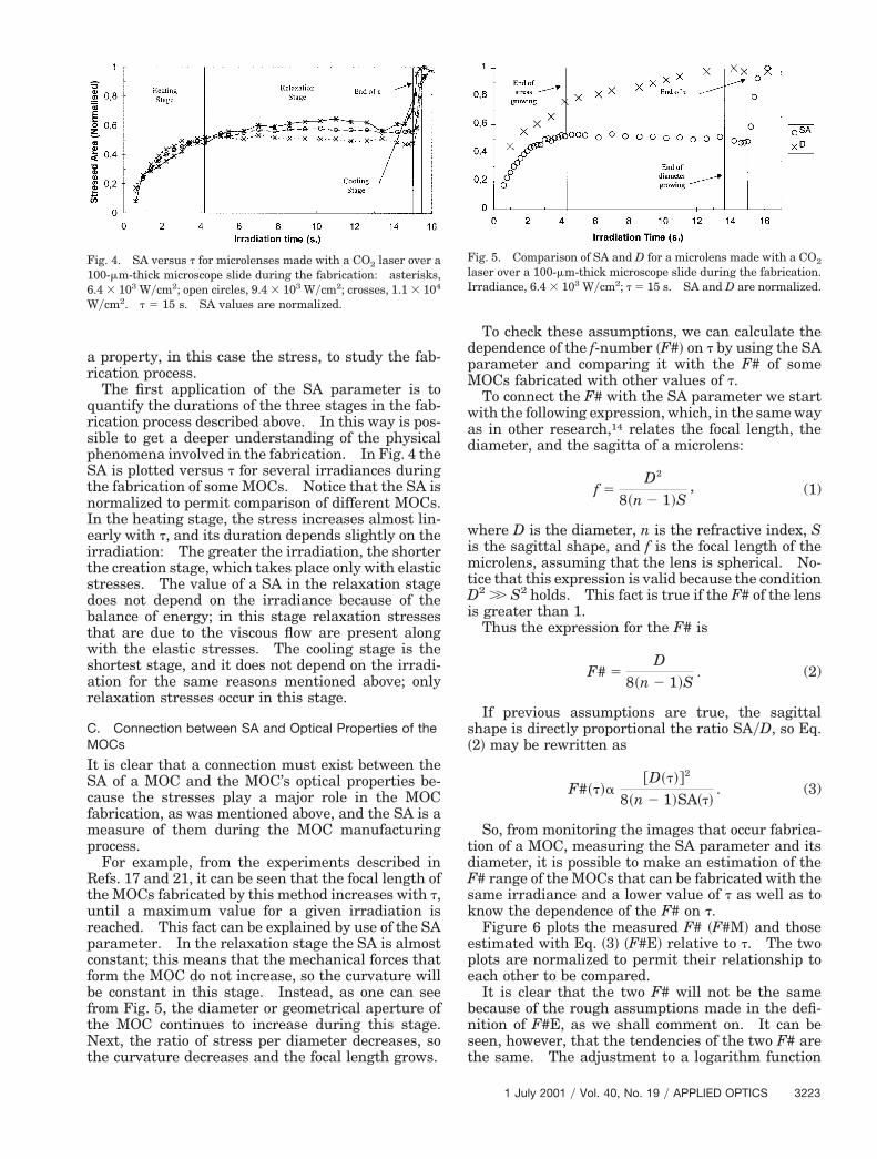
The first application of the SA parameter is toquantify the durations of the three stages in the fab-rication process described above. In this way is pos-sible to get a deeper understanding of the physicalphenomena involved in the fabrication. In Fig. 4 theSA is plotted versus t for several irradiances duringthe fabrication of some MOCs. Notice that the SA isnormalized to permit comparison of different MOCs.In the heating stage, the stress increases almost lin-early with t, and its duration depends slightly on theirradiation: The greater the irradiation, the shorterthe creation stage, which takes place only with elasticstresses. The value of a SA in the relaxation stagedoes not depend on the irradiance because of thebalance of energy; in this stage relaxation stressesthat are due to the viscous flow are present alongwith the elastic stresses. The cooling stage is theshortest stage, and it does not depend on the irradi-ation for the same reasons mentioned above; onlyrelaxation stresses occur in this stage.
C. Connection between SA and Optical Properties of theMOCs
It is clear that a connection must exist between theSA of a MOC and the MOC’s optical properties be-cause the stresses play a major role in the MOCfabrication, as was mentioned above, and the SA is ameasure of them during the MOC manufacturingprocess.
For example, from the experiments described inRefs. 17 and 21, it can be seen that the focal length ofthe MOCs fabricated by this method increases with t,
ntil a maximum value for a given irradiation iseached. This fact can be explained by use of the SAarameter. In the relaxation stage the SA is almostonstant; this means that the mechanical forces thatorm the MOC do not increase, so the curvature wille constant in this stage. Instead, as one can seerom Fig. 5, the diameter or geometrical aperture ofhe MOC continues to increase during this stage.ext, the ratio of stress per diameter decreases, so
he curvature decreases and the focal length grows.
Fig. 4. SA versus t for microlenses made with a CO2 laser over a100-mm-thick microscope slide during the fabrication: asterisks,6.4 3 103 Wycm2; open circles, 9.4 3 103 Wycm2; crosses, 1.1 3 104
Wycm2. t 5 15 s. SA values are normalized.
To check these assumptions, we can calculate thedependence of the f-number ~F#! on t by using the SAparameter and comparing it with the F# of someMOCs fabricated with other values of t.
To connect the F# with the SA parameter we startwith the following expression, which, in the same wayas in other research,14 relates the focal length, thediameter, and the sagitta of a microlens:
f 5D2
8~n 2 1!S, (1)
here D is the diameter, n is the refractive index, Ss the sagittal shape, and f is the focal length of the
icrolens, assuming that the lens is spherical. No-ice that this expression is valid because the condition2 .. S2 holds. This fact is true if the F# of the lens
s greater than 1.Thus the expression for the F# is
F# 5D
8~n 2 1!S. (2)
If previous assumptions are true, the sagittalhape is directly proportional the ratio SAyD, so Eq.
~2! may be rewritten as
F#~t!a@D~t!#2
8~n 2 1!SA~t!. (3)
So, from monitoring the images that occur fabrica-ion of a MOC, measuring the SA parameter and itsiameter, it is possible to make an estimation of the# range of the MOCs that can be fabricated with theame irradiance and a lower value of t as well as tonow the dependence of the F# on t.Figure 6 plots the measured F# ~F#M! and those
estimated with Eq. ~3! ~F#E! relative to t. The twoplots are normalized to permit their relationship toeach other to be compared.
It is clear that the two F# will not be the samebecause of the rough assumptions made in the defi-nition of F#E, as we shall comment on. It can beseen, however, that the tendencies of the two F# arethe same. The adjustment to a logarithm function
Fig. 5. Comparison of SA and D for a microlens made with a CO2
laser over a 100-mm-thick microscope slide during the fabrication.Irradiance, 6.4 3 103 Wycm2; t 5 15 s. SA and D are normalized.
1 July 2001 y Vol. 40, No. 19 y APPLIED OPTICS 3223

relief microlenses fabricated by x-ray lithography and melt-
C
3
gives us a clearer sense of the resemblance of theirtendencies.
The values of F#E are always lower than those ofF#M, as can be explained by the fact we consideredthe shape of the MOC in the cooling stage to be con-stant. Obviously, such is not true because, althoughthis stage is short, there will be some mechanicalrelaxation in the MOC such that the sagittal shape isoverestimated and as a consequence the F#E is un-derestimated. Other assumptions that may notprove true include the spherical shape of the MOC ~inreality it is aspheric in the outer zone! and the beliefthat the external dip is related to the changes in F#E.
So it seems possible from the evolution of the SAand D with t ~we notice that both parameters aregiven by this monitoring method! to choose the properparameters with which to fabricate a MOC with acertain F#. By monitoring a unique MOC with alarge t and measuring its focal length, it is possible toknow the range of F# possible with that irradianceand glass.
4. Conclusions
We have shown that it is possible to monitor thefabrication of micro-optical components by means ofcontrolled laser heating by use of photoelasticity in asimple way. With this method, it is possible to get adeeper understanding of the physical phenomena in-volved in, and perhaps a first step in a quality testsystem for, this fabrication process.
Defining a new parameter, stressed area, we couldestimate the range of F# that can be achieved withcertain parameters. It is also possible to select asuitable t with which to obtain the desired MOC.
All the experiments were performed at the Insti-tuto Tecnologico de Optica, Valencia, Spain ~AIDO!.J. E. Julia acknowledges support from the AIDO dur-ing the carrying out of the experiments.
References1. H. P. Herzig, ed., Micro-Optics: Elements, Systems and Ap-
plications ~Taylor & Francis, London, 1997!.2. J. Gottert, M. Fischer, and A. Muller, “High-aperture surface
Fig. 6. Comparison of F#M and F#E for microlenses made with aO2 laser over a 100-mm-thick microscope slide and an irradiance
of 9.4 3 103 Wycm2. The two curves are normalized.
224 APPLIED OPTICS y Vol. 40, No. 19 y 1 July 2001
ing,” in Proceedings of Conference on Microlens Arrays ~Euro-pean Optical Society, Teddington, UK, 1995!, pp. 21–25.
3. Z. D. Popovic, R. A. Sprague, and G. A. N. Connell, “Techniquefor monolithic fabrication of microlens arrays,” Appl. Opt. 27,1281–1284 ~1988!.
4. N. F. Borrelli and D. L. Morse, “Microlens arrays produced bya photolytic technique,” Appl. Opt. 27, 476–479 ~1988!.
5. D. Daly, R. F. Stevens, M. C. Hutley, and N. Davies, “Themanufacture of microlenses by melting photoresist,” in Micro-lens Arrays, M. C. Hutley, ed., Vol. 30 of IOP Short MeetingsSeries ~Institute of Physics, Bristol, UK, 1991!, pp. 23–34.
6. S. Lazare, J. Lopez, J. Turlet, M. Kufner, S. Kufner, and P.Chavel, “Microlenses fabricated by ultraviolet excimer laserirradiation of poly~methyl methacrylate! followed by styrenediffusion,” Appl. Opt. 35, 4471–4475 ~1996!.
7. X. Wang, J. R. Leger, and R. H. Rediker, “Rapid fabrication ofdiffractive optical elements by use of image-based excimer la-ser ablation,” Appl. Opt. 36, 4660–4665 ~1997!.
8. M. C. Hutley, ed., Microlens Arrays, Vol. 30 of IOP ShortMeetings Series ~Institute of Physics, Bristol, UK, 1991!.
9. S. Haselbeck, H. Schreiber, J. Schwiderand, and N. Streibl,“Microlenses fabricated by melting photoresist on a base lay-er,” Opt. Eng. 32, 1322–1324 ~1993!.
10. B. P. Keyworth, D. J. Corazza, J. N. McMullin, and L. Mabbott,“Single-step fabrication of refractive microlens arrays,” Appl.Opt. 36, 2198–2202 ~1997!.
11. S. Calixto and Z. Malacara, “Micromirror fabrication usingdye-doped plastic,” Opt. Eng. 37, 2320–2323 ~1998!.
12. V. P. Veiko and Y. B. Yakovlev, “Physical fundamentals oflaser forming of micro-optical components,” Opt. Eng. 33,3567–3571 ~1994!.
13. M. Wakaki, Y. Komachi, and G. Kanai, “Microlenses and mi-crolens arrays formed on a glass plate by use of a CO2 laser,”Appl. Opt. 37, 627–631 ~1998!.
14. G. Beadie and N. M. Lawandy, “Single-step laser fabrication ofrefractive microlenses in semiconductor-doped glasses,” Opt.Lett. 20, 2153–2155 ~1995!.
15. S. Calixto and G. Paez Padilla, “Micromirrors and microlensesfabricated on polymer materials by means of infrared radia-tion,” Appl. Opt. 35, 6126–6130 ~1996!.
16. A. C. Tam, I. K. Pour, and P. Baumgart, “New laser texturingprocess of magnetic disks for stiction reduction,” in Laser Pro-cessing of Materials and Industrial Applications, S.-S. Dengand S. C. Wang, eds., Proc. SPIE 2888, 97–107 ~1996!.
17. J. E. Julia and R. Estrela, “On-line monitoring of the manu-facture process of optical microelements by laser heating,” inOptical Diagnostics of Materials and Devices for Opto-, Micro-,and Quantum Electronics IV, Proc. SPIE ~in press!.
18. J. W. Dally and W. F. Riley, Experimental Stress Analysis~McGraw-Hill, Kogakusha, Tokyo, 1978!.
19. F. Dahmani, A. W. Schnid, J. C. Lambropoulos, and S. Burns,“Dependence of birrefrigence and residual stress near laser-induced cracks in fused silica on laser fluence and on laser-pulse number,” Appl. Opt. 37, 7772–7784 ~1998!.
20. A. R. Boyain y Goitia, A. N. Starodumov, D. Monzon-Hernandez, V. N. Filippov, and P. Gavrilovic, “Birrefrigencemeasurement in double-clad fiber lasers with large cross sec-tion,” Appl. Opt. 39, 2259–2263 ~2000!.
21. V. P. Veiko, A. K. Kromin, and E. B. Yakovlev, “Laser fabri-cation of MOC based on soft laser heating of glass and glass-like materials,” in Miniature and Micro-Optics andMicromechanics, N. C. Gallagher and C. S. Roychoudhuri, eds.,Proc. SPIE 1992, 159–167 ~1993!.


![Lecture 2 - optical fiber fabrication [Autosaved]](https://img.pdfslide.net/doc/110x75/54730038b4af9f03128b45fa/lecture-2-optical-fiber-fabrication-autosaved.jpg)