Embed Size (px)
Citation preview
© LEP International Co, Ltd.
One Control | Crocodile Tail Loop
Thank you for your purchase of the Crocodile Tail Loop by One Control.
The crocodile Tail Loop is the flagship switcher from One Control. Create up to 70 presets with the easy push button auto saving system. The OC10 has 7 programs per bank and you can choose up to 10 programs for each program. The OC10 also is equipped midi and can send program changes or to be used as a midi through to be used in combination with other midi devices. Link two OC10 together with a simple LAN cable to access multiple pedals off stage. The OC10 also has the amazing BJF buffer from One Control included and also can be bypassed by using the not buffered input. The OC10 can also be a simple switcher but accessing the direct mode. Perfect for band practices or experimenting with pedals before you’ve decided how to set your programs. The Crocodile Tail Loop truly is one of the most innovative pedal switchers on the market.
To get the full potential of the unit and to avoid misuse, please read this user guide carefully.
PGM1/L1 — PGM7/L7 These switches instantly recall the presets stored in the corresponding program (1 - 7) when pressed in PGM mode. They directly turn loops 1 - 7 on or off when pressed in DIRECT mode.BANK UP/L8 In PGM mode, this switch increases the bank, there are 10 banks available (1,2,3,4,5,6,7,8,9,0), in DIRECT mode, this switch turns on/off loop 8.
1
2
1
5 2345678 91011
12 13
BANK DN/L9 In PGM mode, this switch decreases the bank, in DIRECT mode, this switch turns on/off loop 9.
LINK CONFIG LINK config feature is active only in PGM mode, push the tact switch to config the mode, - SYNC mode, M/S LEDs are both off - DOWNLOAD MASTER mode, M/S red LED is on. - DOWNLOAD SLAVE mode, M/S green led is on.Check LINK section for more detail.
34
5 MIDI ON/OFF MIDI config feature is active only in PGM mode, push the tact switch to config the mode, - If TX is on, OC10 will transmit program change through MIDI OUT jack. - If RX is on, OC10 will listen to the program change command through MIDI IN jack. Check MIDI section for more detail.
56 Program Buttons IN PGM mode these buttons turn on / off LOOP1 to LOOP10 separately, the signal sends to the loop which is turned on ( LED on). in DIRECT mode the buttons are disabled.
7 LED Display In PGM mode, the LED shows the bank number, it shows “ ” in DIRECT MODE.
8 TUNER/L10 In PGM mode, this switch shuts off the OUT-1 and OUT-2 and switches the input to TUNER jack, press it again will get back to normal operation. In DIRECT mode the switch turns on/off loop 10.
Page 1
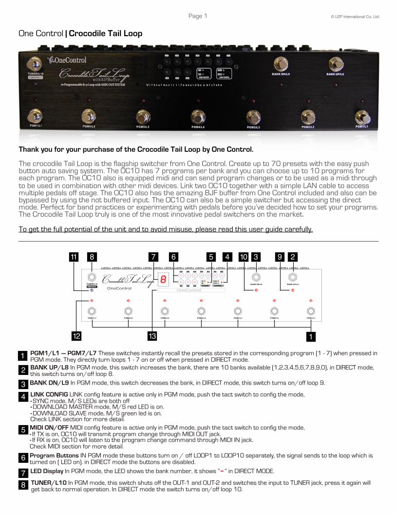
STATUS LED In PGM mode it turns on when its corresponding program is recalled. In DIRECT mode it will turn on when its corresponding loop is engaged.
9 STATUS LED The LED only be active in DIRECT MODE, it turns on when loop 8 is engaged.
10 STATUS LED The LED only be active in DIRECT MODE, it turns on when loop 9 is engaged.
11 STATUS LED The LED shows TUNER ON/OFF status in PGM mode, in DIRECT mode it will turn on when loop 10 is engaged.
12
13 GUARD BAR The guard bar protects the buttons and display panel, it is remove-able.
15 12 817 1411 13
1 5 6 92 83 74 1016
MIDI OUT/THRU The toggle switch setups the MIDI JACK for “OUTPUT” or “THRU” function.1LINK Connect the link cable here.29V IN Connect to an external 9V DC power source 5.5x2.1mm center negative.3BUF IN Signal input via this jack is fed to a buffer circuit prior to being sent to the loops.4
5 BUF OUT The input signal received at the BUF-IN jack is directly output via the BUF OUT jack prior to being send to loops.
6 TUNER When OUT are muted, the input signal via buffered or non-buffered reaches this jack.
7 INPUT The toggle switch setups the MIDI JACK for “OUTPUT” or “THRU” function.
8 OUT1 and OUT2 Output jacks for series loops (LOOP1- 7), the input signal via buffered or non-buffered Input jacks reaches the two jacks via the 7 series loops, OUT-1 and OUT-2 jacks are Internally connected in parallel.
IN8 - IN9 - IN10 Input of separate LOOP8–10. prior to sending to loops.
SEND 1–7 Send jacks of LOOP1–7, connect to input jack of guitar pedals.
S8 - S9 - S10 SEND jack of separate LOOP8, LOOP9,LOOP10, the jacks should be connected to the input of guitar pedals. These jacks also function as latching N.C (Normally Closed) switch which works as foot-switch to control amplifier channel. The sleeve and tip of the jack are “closed”/“open” when the loop is “off/on”.
910 RETURN 1–7 Return jacks of LOOP1–7, connect to output jack of guitar pedals.
1112
R8 - R9 - R10 Return jack of separate LOOP8, LOOP9,LOOP10, the jacks should be connected to the output of guitar pedals.
13
14 OUT8 - OUT9 - OUT10 Output jack of separate LOOP8, LOOP9, LOOP10, the jacks also function as latching N.O (Normally Open) switches which work as foot-switch to control amplifier channel. The sleeve and tip of the jack are “open”/“closed” when the loop is off/on.MIDI IN Receives MIDI data from an external MIDI device, the MIDI IN is not available in when it is set as DOWNLOAD SLAVE device. Check detail in MIDI and LINK sections.
15
16 MIDI OUT/THRU Transmits MIDI data to an external MIDI device.
17 GROUND STUB Connect the stub to earth to ground the frame.
Page 2
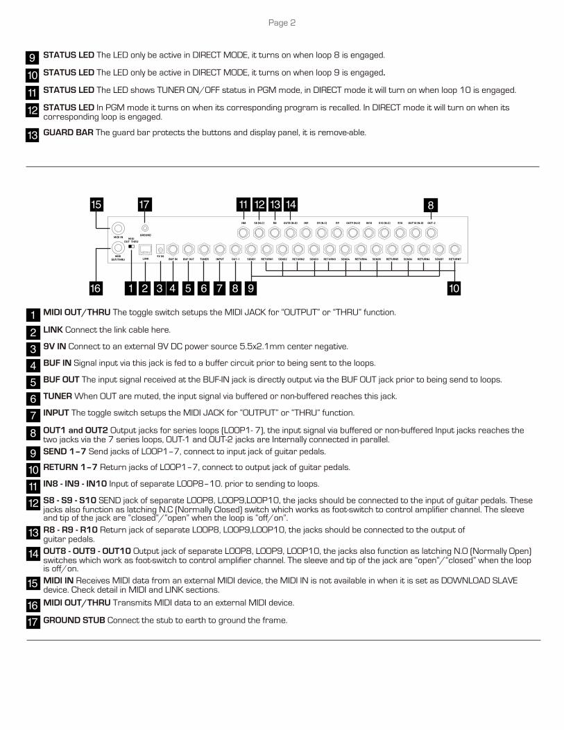
Signal Path
Guitar signal feeds into OC10 input (NBUF IN or BUF IN), enters series LOOP1~LOOP7 when MUTE switch is off, then outputs from OUT-1 and OUT-2. when TUNER switch is pushed, the signal outputs to TUNER jack. Be noted the BUF OUT jack doesn’t output when the guitar plug into NBUF IN jack.
Recall ProgramsPress preset switches to recall presets, the corresponding LED lights up when a preset is active. Recall / bypass operation will not change the MUTE status.
Bank UP/DOWNOc10 have 10 banks from 1 to 10(”0"), each bank store 7 programs. Press BANK UP or BANK DOWN switches to change the bank, the numerical bank display blinks when the bank is about to be changed. Press any PGM switch to recall new bank programs.
Programming the loopsPress the program buttons to turn on/off corresponding loops, the loop status LED will be on/off accordingly, the memory automatically stores the status of all loops.
TUNERPress TUNER/L10 switch the guitar signal to TUNER jack and mute the output (OUT-1 and OUT-2) at the same time. Press the switch again will switch back the guitar signal to loops.TUNER function works individually, recalling programs do not affect TUNER function.
PGM/ DIRECT MODEOc10 is able to work in DIRECT mode, holding the TUNER/L10 switch for 3 seconds will turn on DIRECT mode, the numerical display shows “-”. In DIRECT mode each stomp switch (L1 ~ L10) turns on/off the loop1~loop10 separately. holding the TUNER/L10 switch for 3 seconds will turn off DIRECT mode and back to PGM mode. Note: in DIRECT mode the MIDI and LINK function are not available.
Configurate MIDIA program allows to enable/disable the MIDI functions. Press MIDI ON/OFF button to turn on/off the transmit (TX) and receive(RX) of MIDI, TX/RX led’s show the on/off status. The TX/RX status is stored into a PGM automatically. When the TX is on, a PGM recall will transmit a “MIDI program change” command via MIDI OUT jack on MIDI channel 0. The program change number is from 0 to 69, the number of Bank 1/PGM 1 is 0, the number of BANK 10/PGM7 is 69. When the RX is on, a “MIDI program change” on MIDI channel 0, from an external MIDI device will recall the corresponding PGM of Oc10. if program change number is 0, it recalls BANK 1/PGM1 on Oc10.
LINK FUNCTIONOc10 allows to link to another Oc10 and work together. There’re 2 link modes, SYNC and DOWNLOAD mode. In SYNC mode, a PGM recall will cause the same PGM recall on another unit, for example, recall BANK 1/ PGM7 on Oc10 A, the BANK1/PGM7 on Oc10 B will be recalled simultaneously, if press PGM7 of BANK 2 on Oc10 B, the BANK2/PGM7 on Oc10 A will be recalled at the same time.In DOWNLOAD mode, the MASTER Oc10 downloads the data to the SLAVE Oc10. The SLAVE Oc10 duplicates the MASTER Oc10.Push the LINK CONFIG button changes the LINK mode. The mode is SYNC when M/S led is off. The mode is DOWNLOAD MASTER when M/S led is red. The mode is DOWNLOAD SLAVE when M/S led is green.The blue LINK led lights on when two Oc10 are connected with LINK cable. Note: The MIDI IN is not available when Oc10 is set as DOWNLOAD SLAVE device
Page 3
SpecificationsPOWER SUPPLY: DC9V CURRENT DRAIN: max. 450mAINPUT IMPEDANCE: 500K OhmOUTPUT IMPEDANCE: 10K OhmMAX. BUFFERED INPUT: 9VMAX NON_BUFFERED OUTPUT: 30VDIMENSIONS: 462x110x64 mm — 18.2x4.35x2.5 InchWEIGHT: 1800g — 4 lb.
WarrantyRepairs or exchanges under warranty are subject to these warranty guidelines: This product is covered under our warranty for the period of 1 year from date of purchase, as filled out on the warranty card. In the case the product needs to be shipped, the cost of shipping will be paid by the buyer.The Following are not covered by this warranty:Fire, earthquake, natural disasters such as flooding, material breakage, or war. Warranty is void if there is any trace of repair or modification that is not performed or authorized by LEP International.
One Control by LEP International Co, LTD.9-16 Suehiro HanamakiIwate 025-0079, JapanPhone: 0198-23-6600 Fax: [email protected]
Page 4