Embed Size (px)
Citation preview
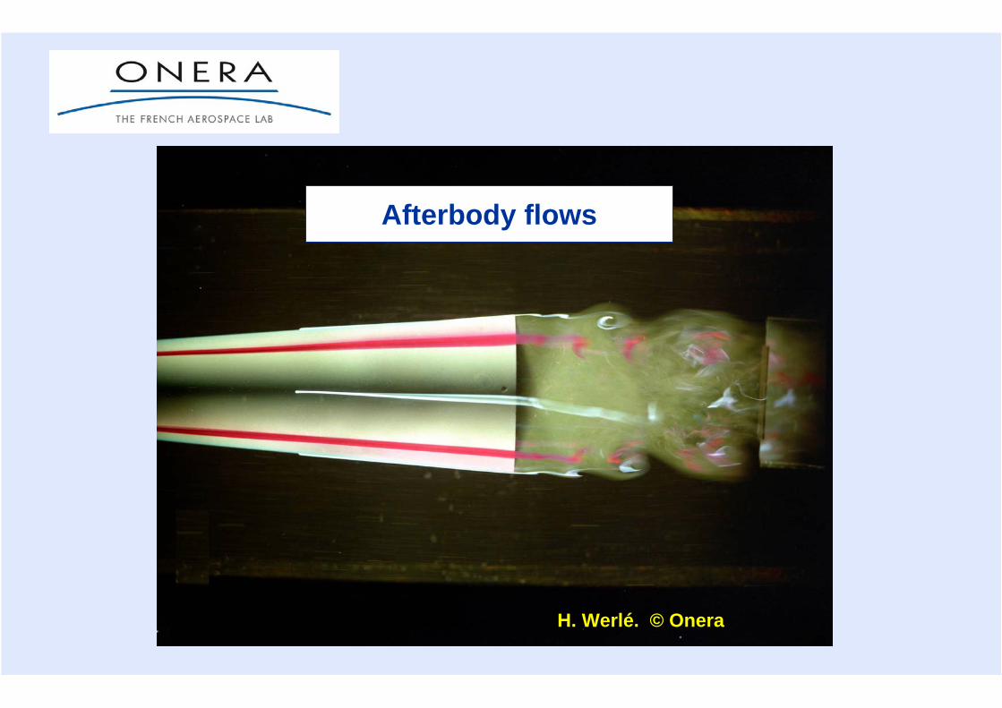
Afterbody flows
H. Werlé. © Onera

Afterbody flows
1. Non-propelled afterbody
2. Propelled afterbody without base
3. Propelled afterbody with base
4. Rectangular section afterbody
5. Two-nozzle afterbody
6. Flow past an automobile
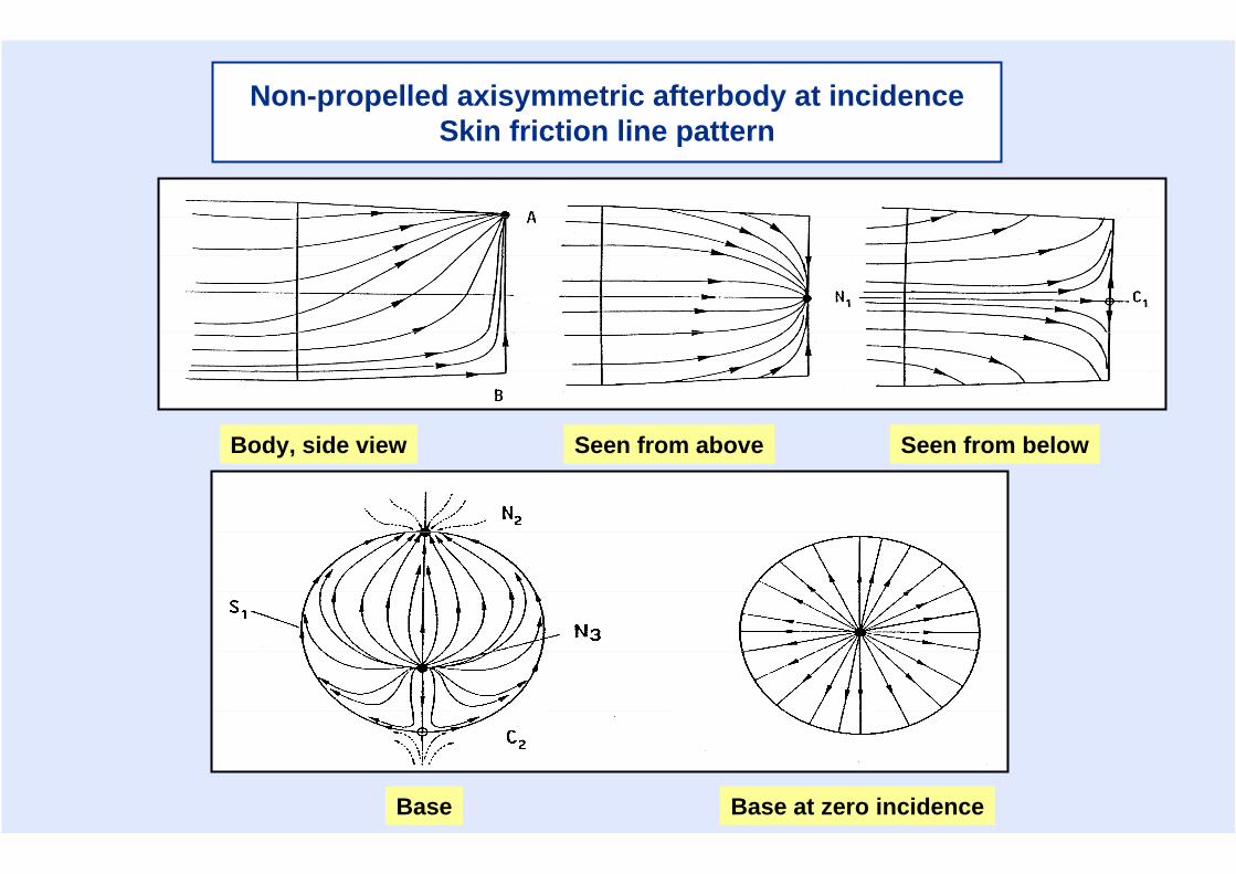
Non-propelled axisymmetric afterbody at incidenceSkin friction line pattern
Body, side view Seen from above Seen from below
Base at zero incidenceBase
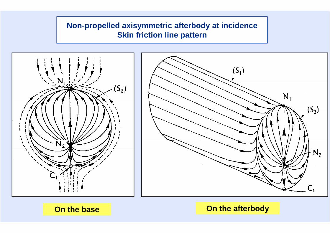
On the base On the afterbody
Non-propelled axisymmetric afterbody at incidenceSkin friction line pattern
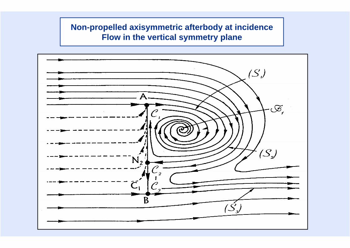
Non-propelled axisymmetric afterbody at incidenceFlow in the vertical symmetry plane
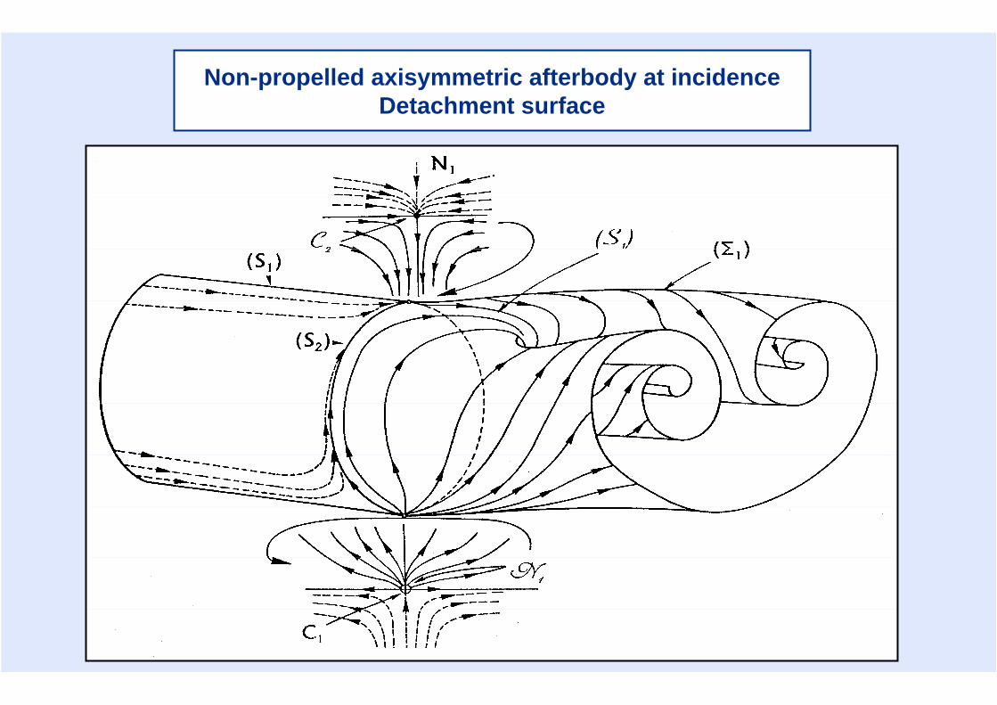
Non-propelled axisymmetric afterbody at incidenceDetachment surface
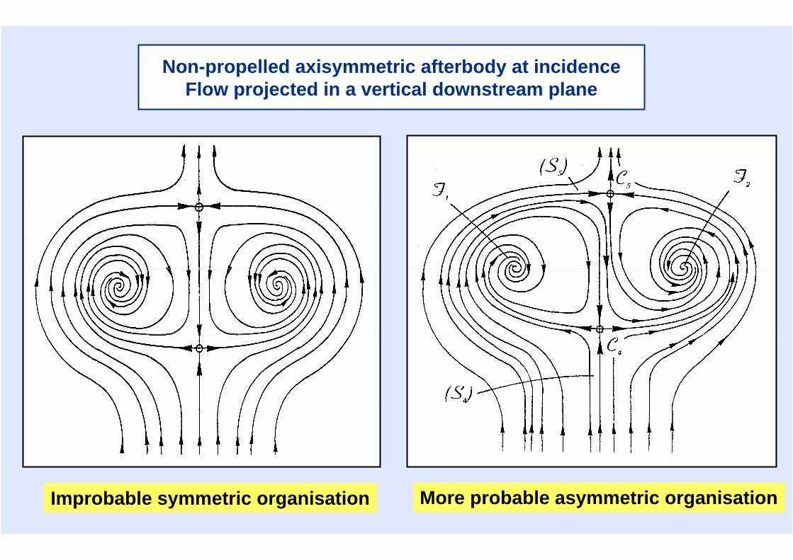
Improbable symmetric organisation More probable asymmetric organisation
Non-propelled axisymmetric afterbody at incidenceFlow projected in a vertical downstream plane
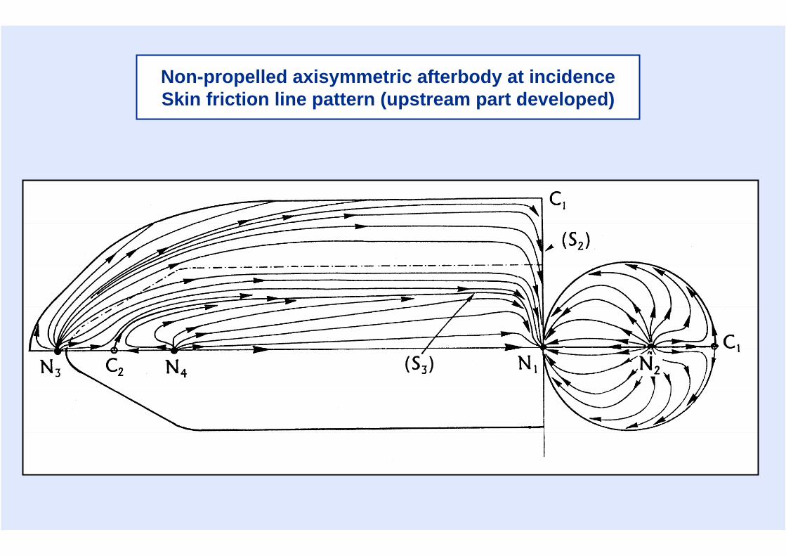
Non-propelled axisymmetric afterbody at incidence Skin friction line pattern (upstream part developed)
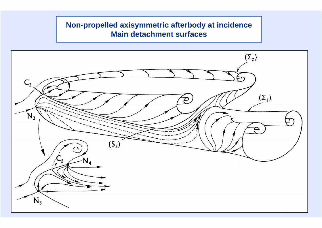
Non-propelled axisymmetric afterbody at incidenceMain detachment surfaces
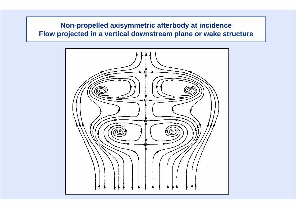
Non-propelled axisymmetric afterbody at incidenceFlow projected in a vertical downstream plane or wake structure

Propelled afterbody without base at incidence Skin friction line pattern and separation surface
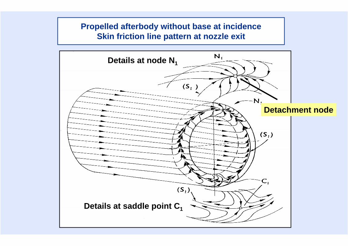
Details at node N1
Details at saddle point C1
Detachment node
Propelled afterbody without base at incidence Skin friction line pattern at nozzle exit
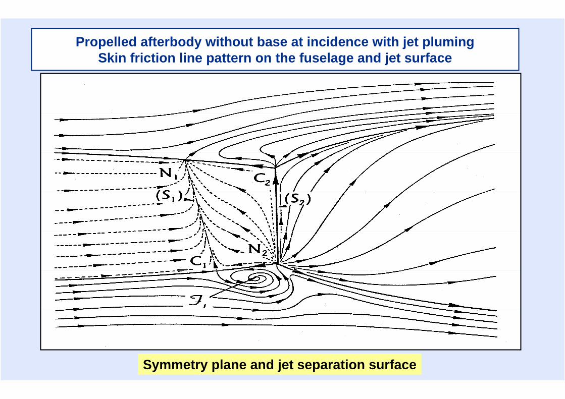
Propelled afterbody without base at incidence with jet plumingSkin friction line pattern on the fuselage and jet surface
Symmetry plane and jet separation surface

Propelled afterbody without base and jet plumingMain detachment surfaces
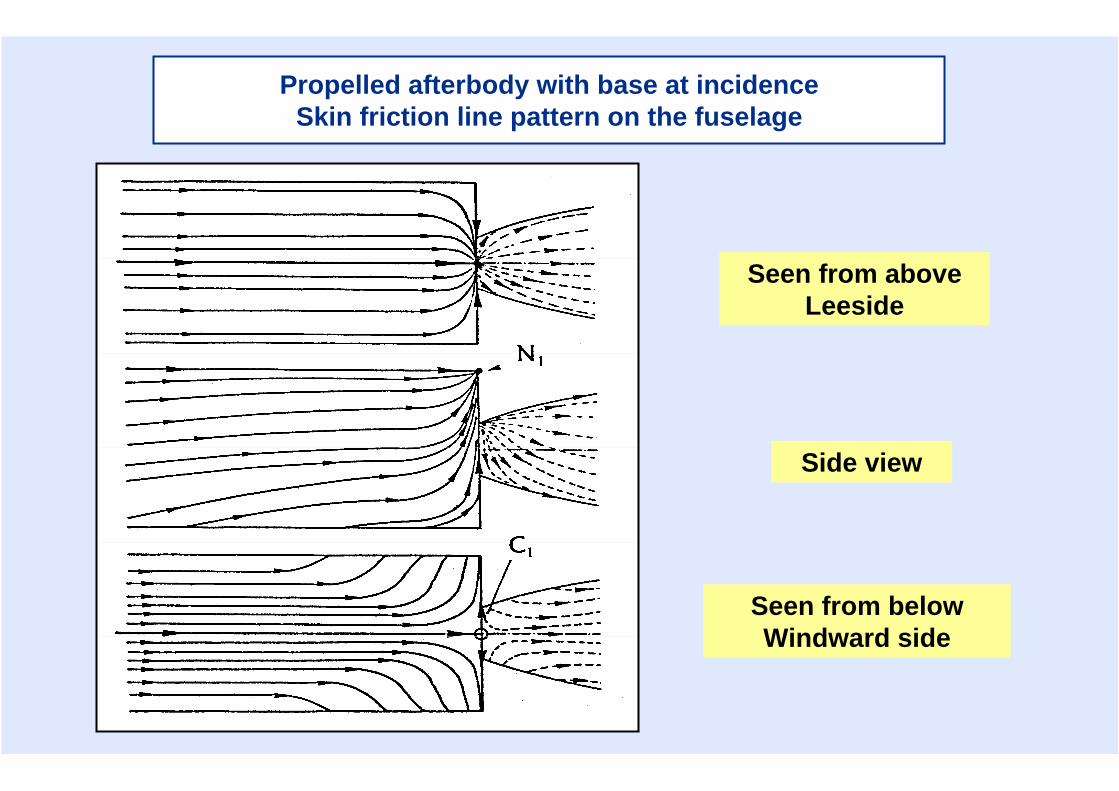
Propelled afterbody with base at incidenceSkin friction line pattern on the fuselage
Seen from aboveLeeside
Side view
Seen from belowWindward side
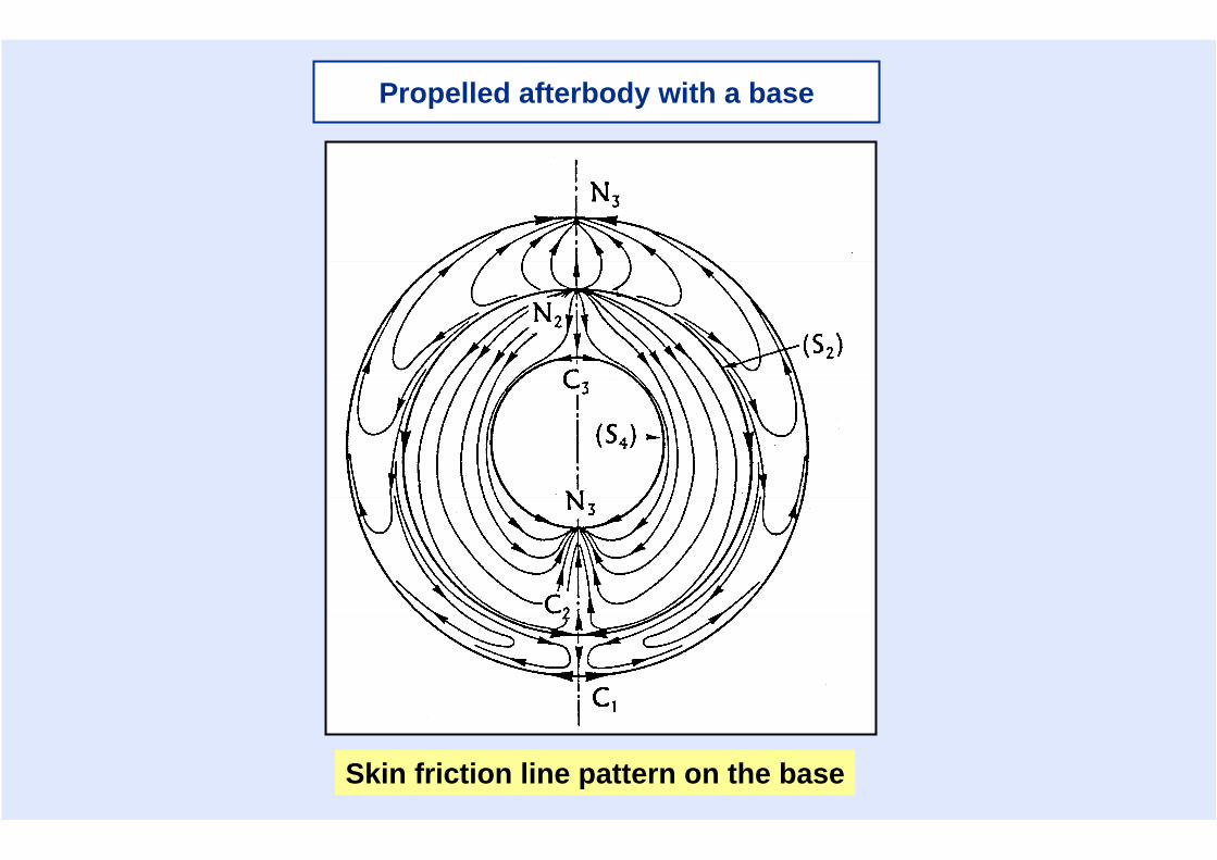
Propelled afterbody with a base
Skin friction line pattern on the base
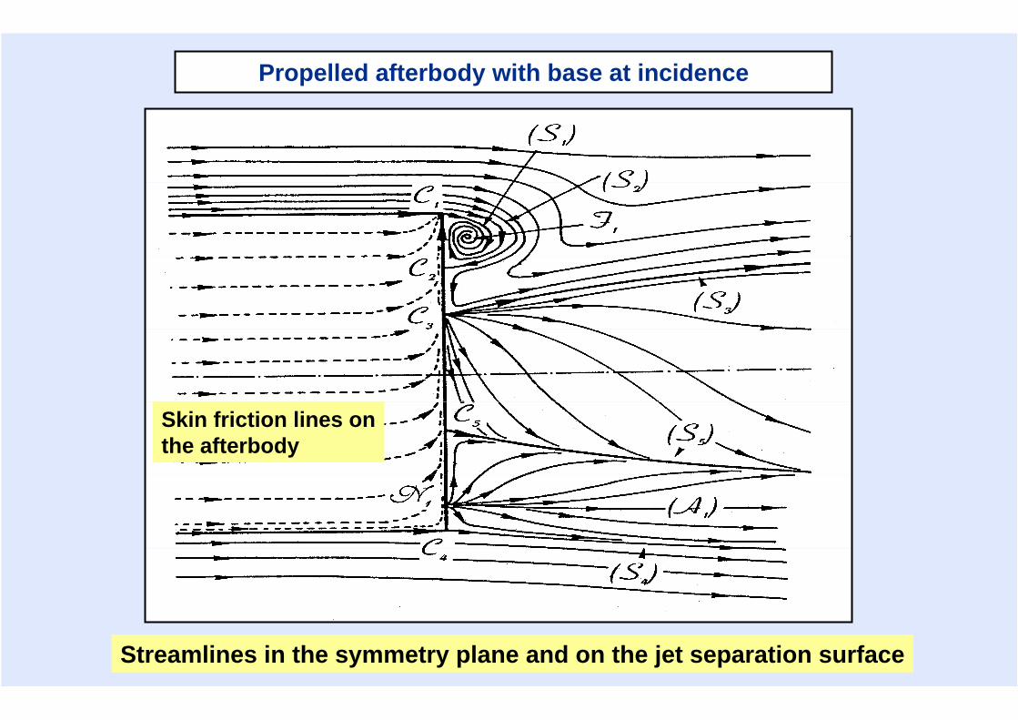
Propelled afterbody with base at incidence
Streamlines in the symmetry plane and on the jet separation surface
Skin friction lines onthe afterbody
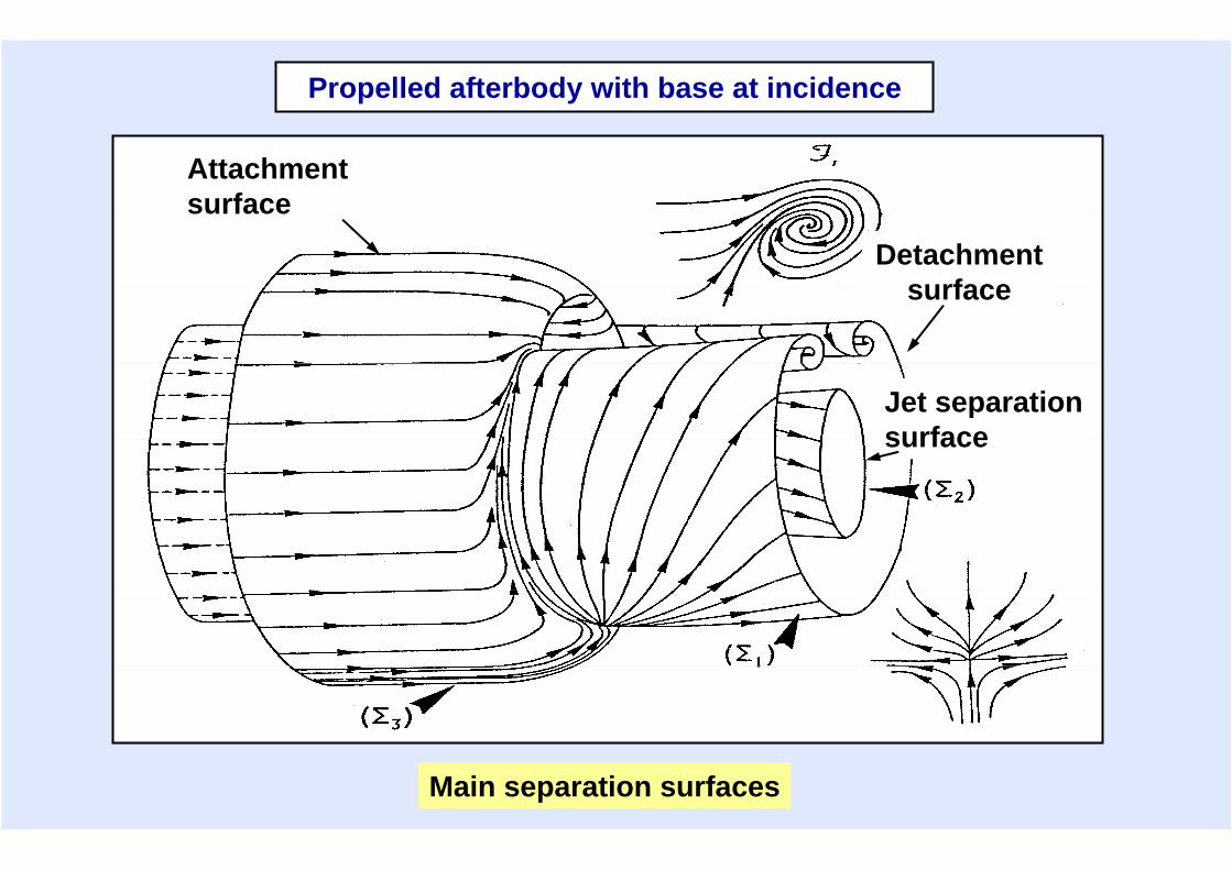
Detachment surface
Attachment surface
Jet separationsurface
Main separation surfaces
Propelled afterbody with base at incidence
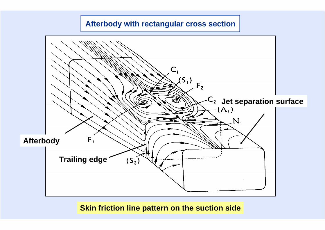
Afterbody with rectangular cross section
Jet separation surface
Afterbody
Trailing edge
Skin friction line pattern on the suction side
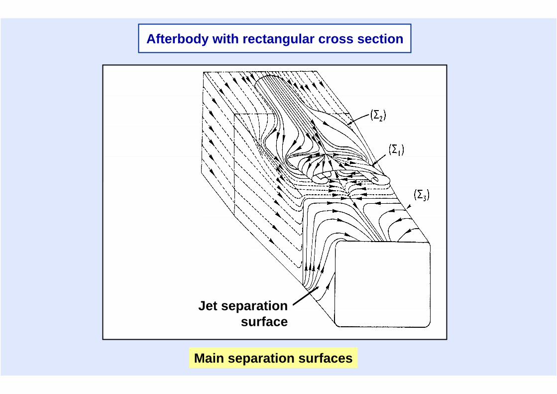
Main separation surfaces
Jet separation surface
Afterbody with rectangular cross section
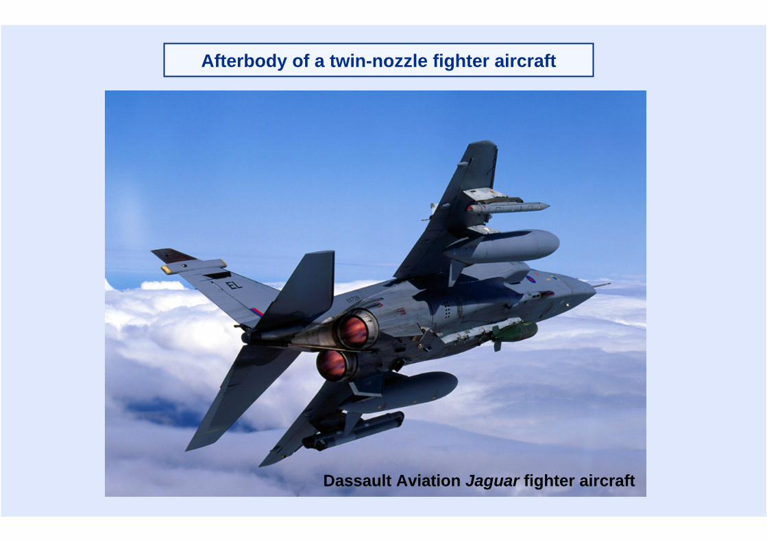
Afterbody of a twin-nozzle fighter aircraft
Dassault Aviation Jaguar fighter aircraft
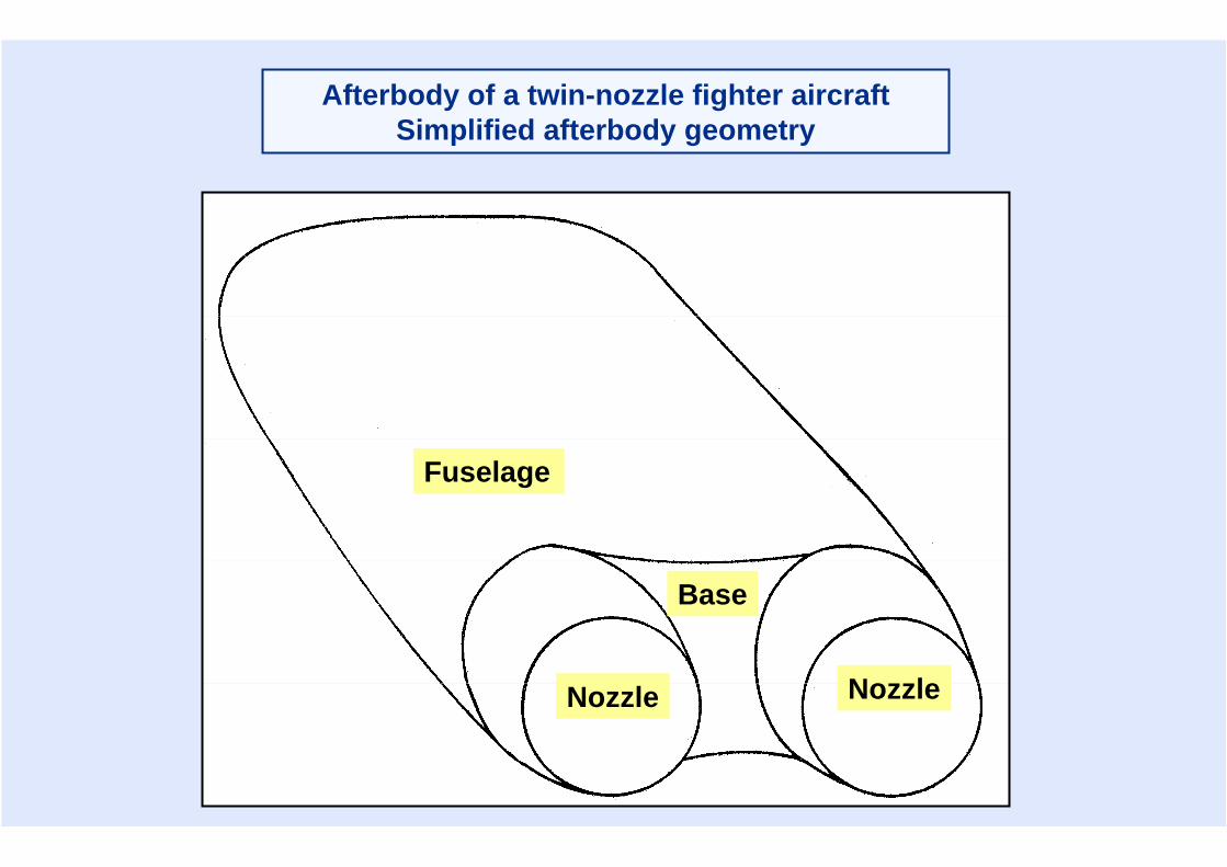
Fuselage
Base
Nozzle
Afterbody of a twin-nozzle fighter aircraftSimplified afterbody geometry
Nozzle
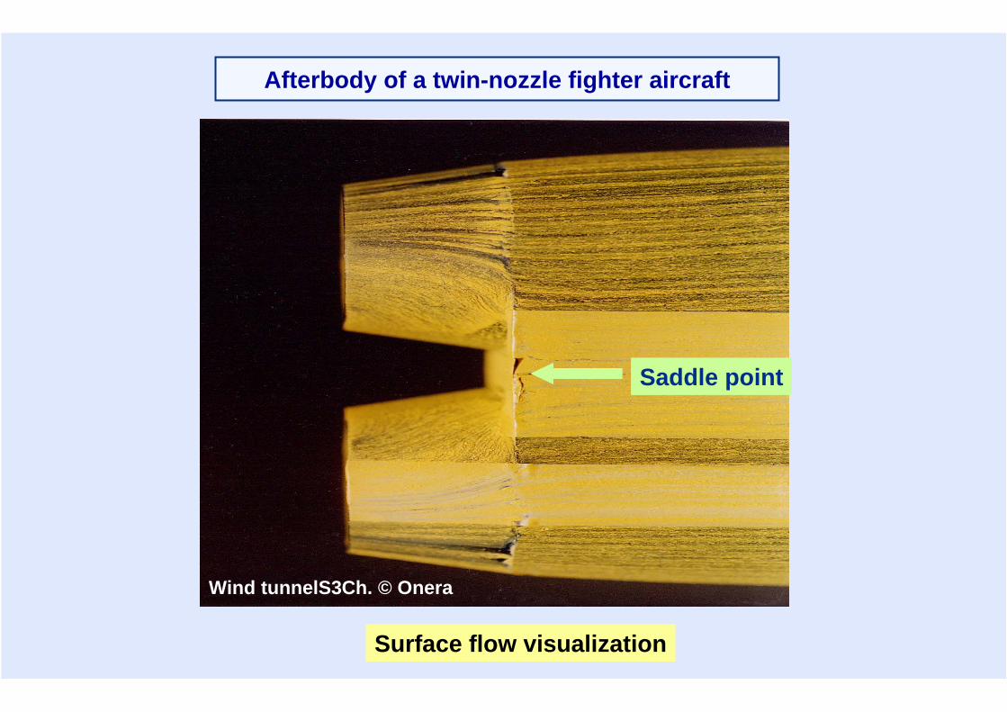
Saddle point
Wind tunnelS3Ch. © Onera
Surface flow visualization
Afterbody of a twin-nozzle fighter aircraft

Skin friction line pattern
Afterbody of a twin-nozzle fighter aircraft
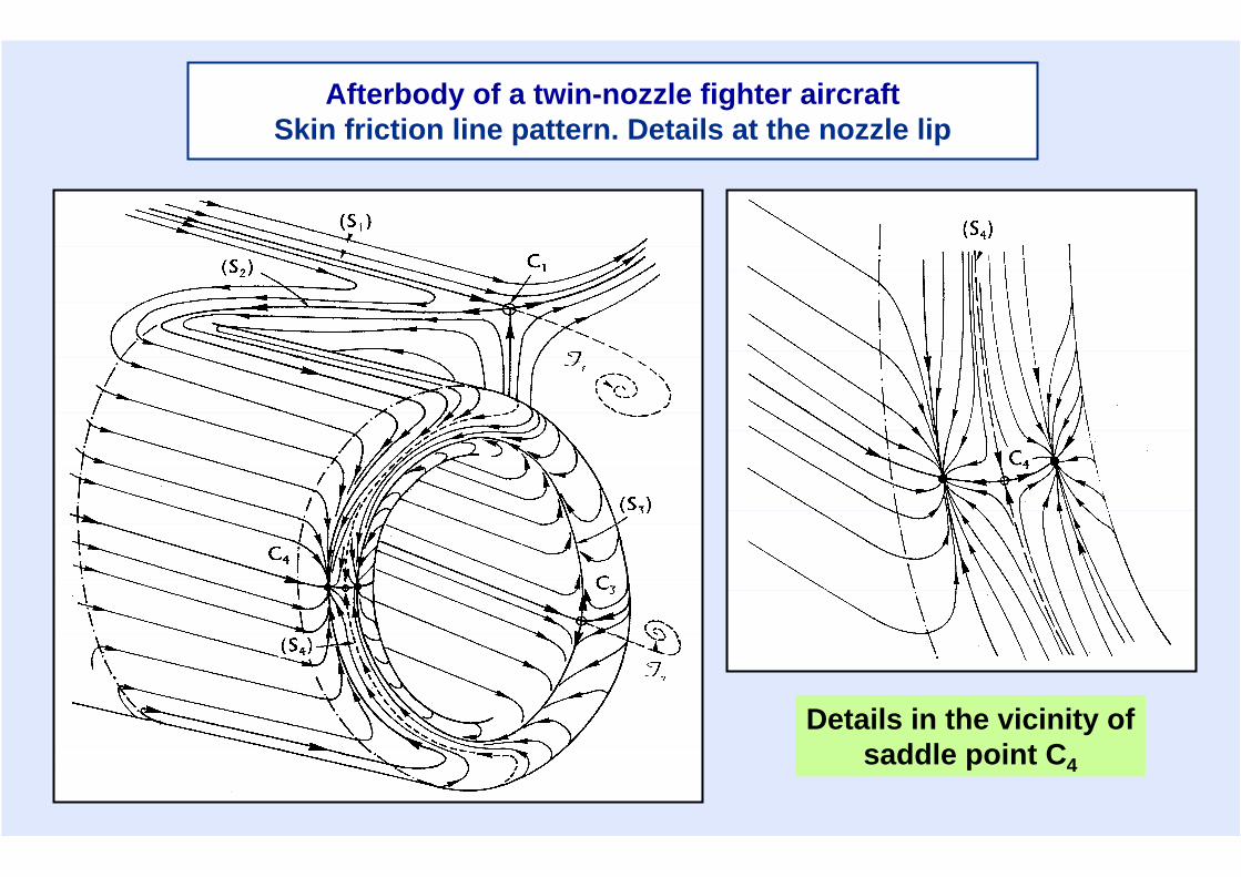
Afterbody of a twin-nozzle fighter aircraftSkin friction line pattern. Details at the nozzle lip
Details in the vicinity ofsaddle point C4

Wind tunnel S3Ch. © Onera
Schlieren visualisation of the jets
Afterbody of a twin-nozzle fighter aircraft
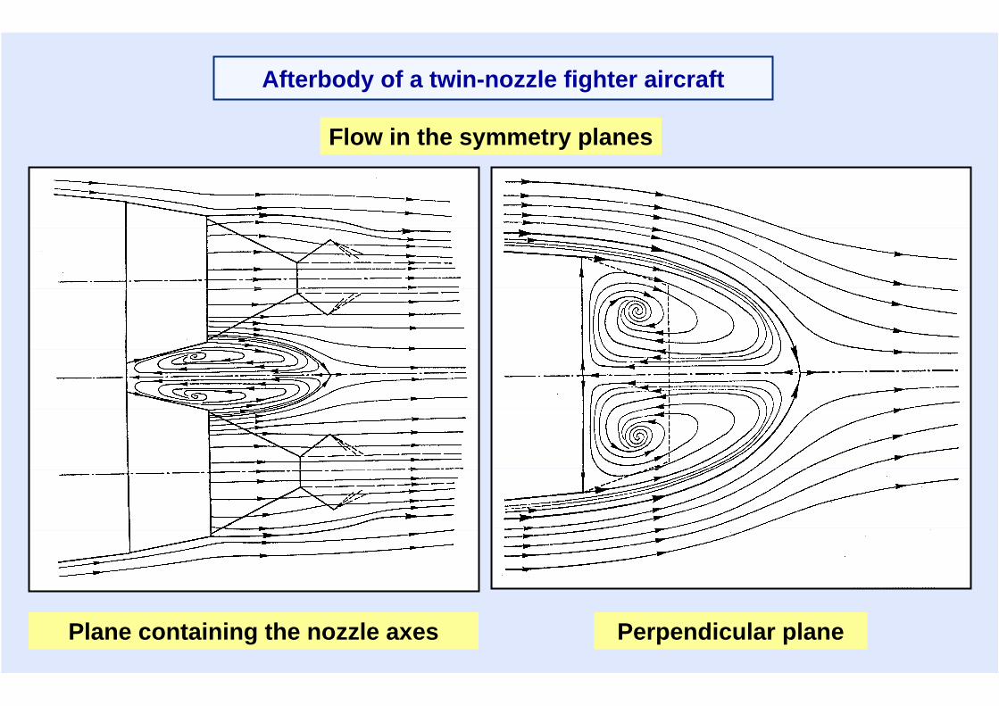
Plane containing the nozzle axes Perpendicular plane
Flow in the symmetry planes
Afterbody of a twin-nozzle fighter aircraft
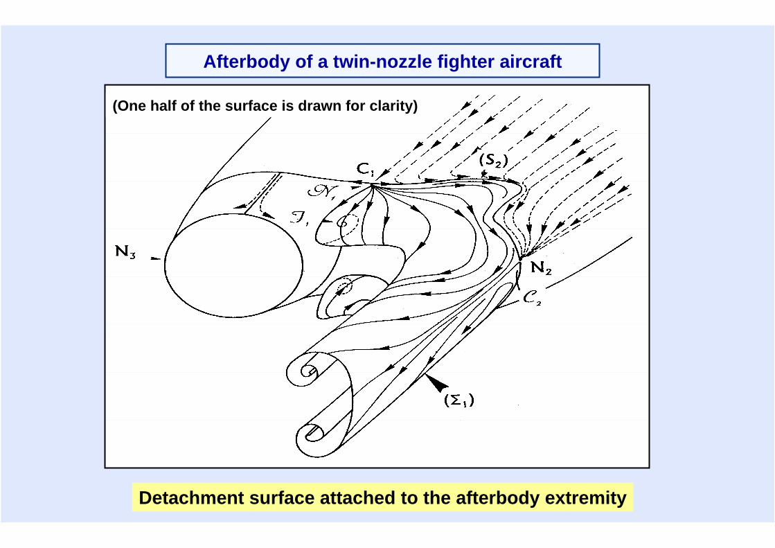
Detachment surface attached to the afterbody extremity
Afterbody of a twin-nozzle fighter aircraft
(One half of the surface is drawn for clarity)
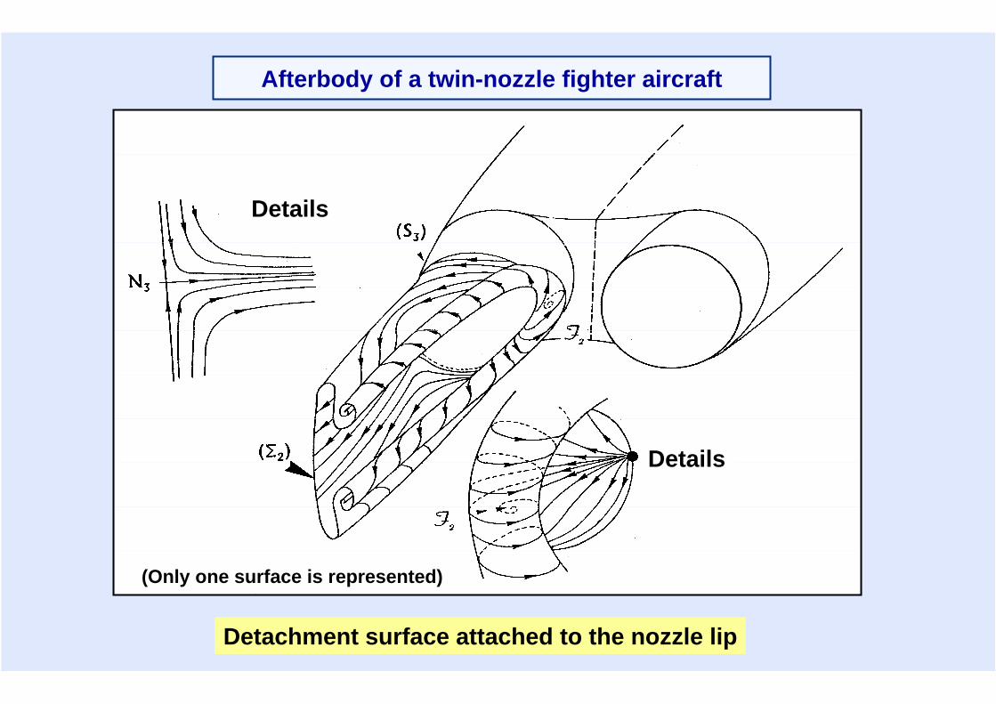
(Only one surface is represented)
Details
Details
Detachment surface attached to the nozzle lip
Afterbody of a twin-nozzle fighter aircraft
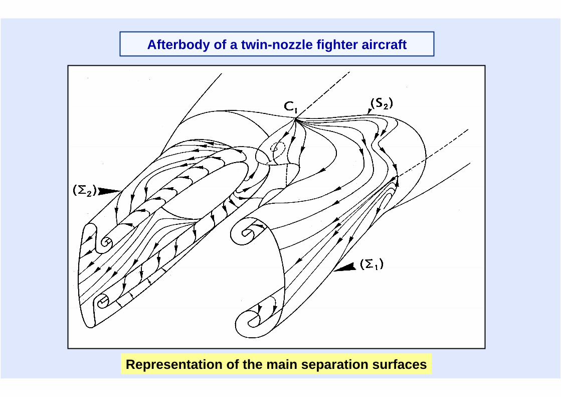
Representation of the main separation surfaces
Afterbody of a twin-nozzle fighter aircraft
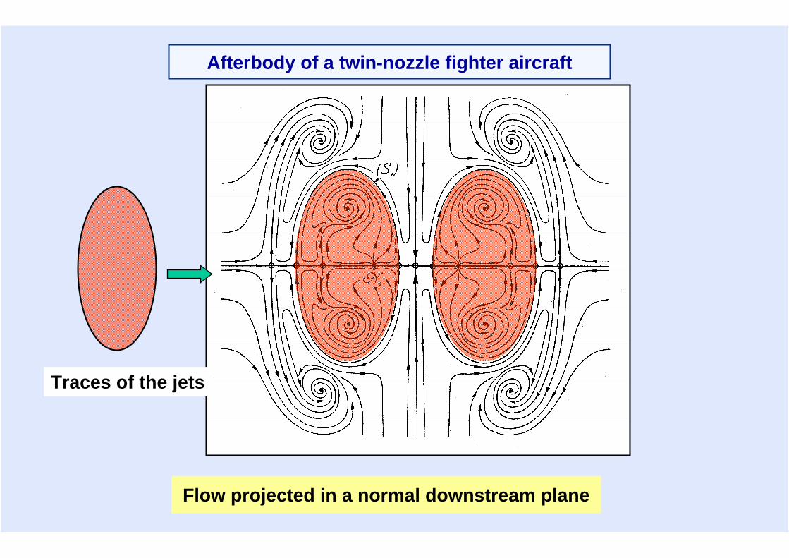
Flow projected in a normal downstream plane
Traces of the jets
Afterbody of a twin-nozzle fighter aircraft
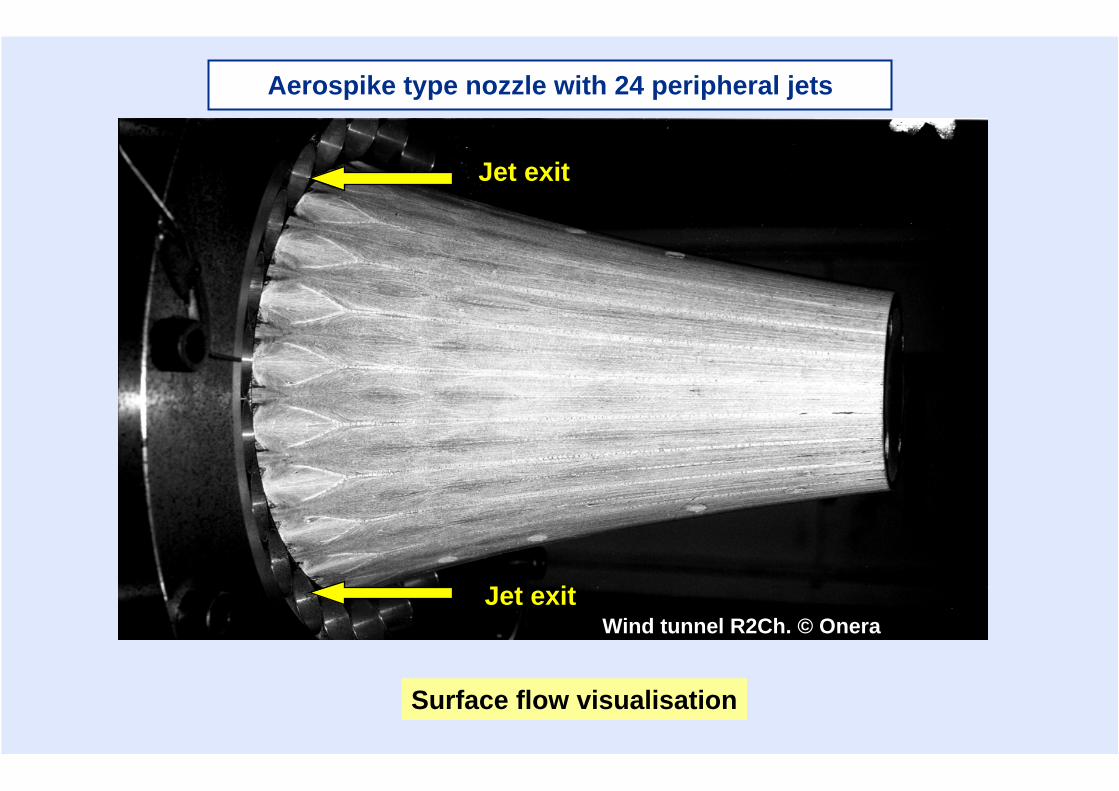
Aerospike type nozzle with 24 peripheral jets
Jet exit
Jet exitWind tunnel R2Ch. © Onera
Surface flow visualisation
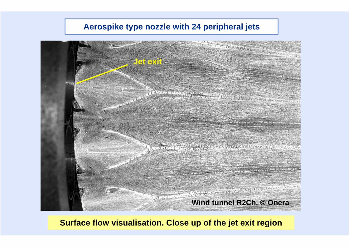
Surface flow visualisation. Close up of the jet exit region
Jet exit
Wind tunnel R2Ch. © Onera
Aerospike type nozzle with 24 peripheral jets
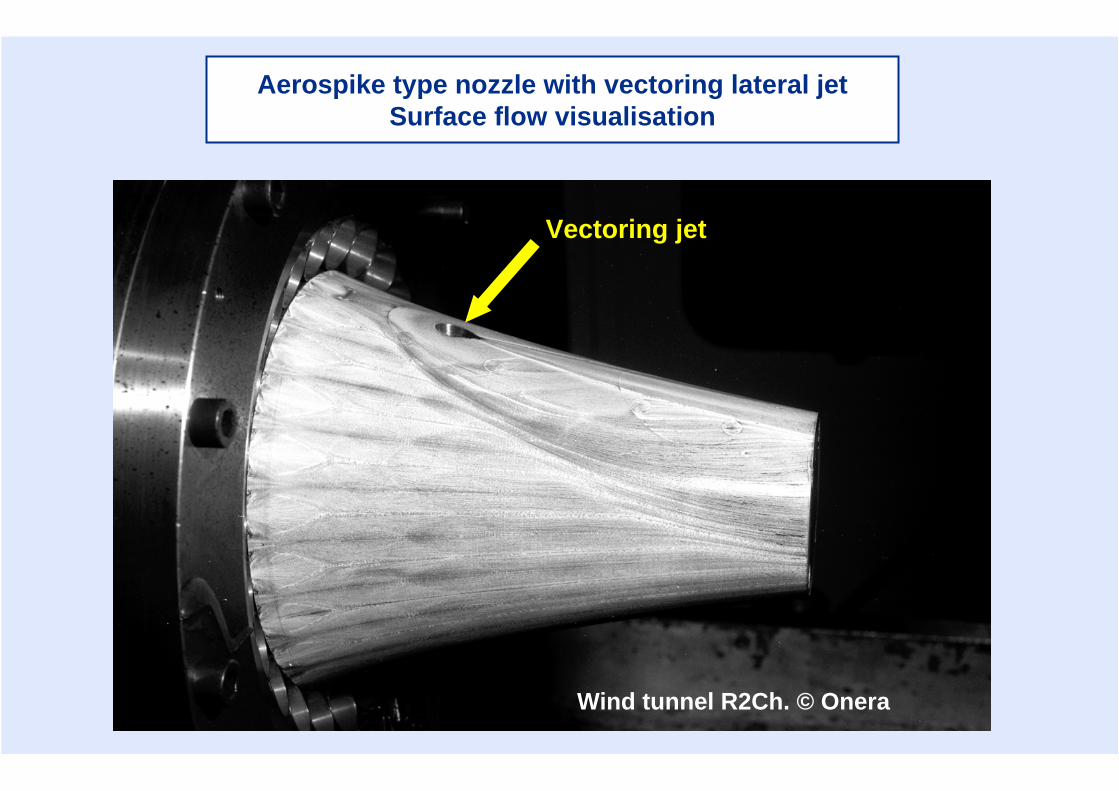
Aerospike type nozzle with vectoring lateral jetSurface flow visualisation
Vectoring jet
Wind tunnel R2Ch. © Onera
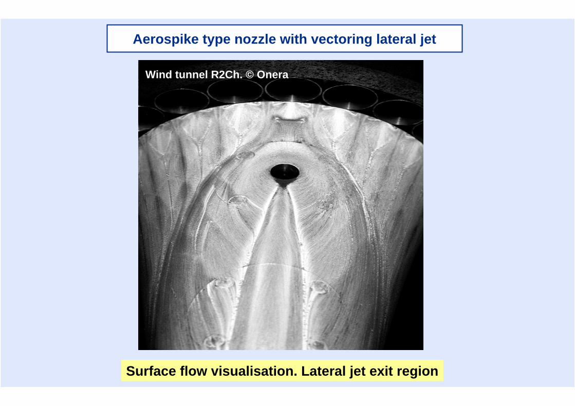
Wind tunnel R2Ch. © Onera
Surface flow visualisation. Lateral jet exit region
Aerospike type nozzle with vectoring lateral jet
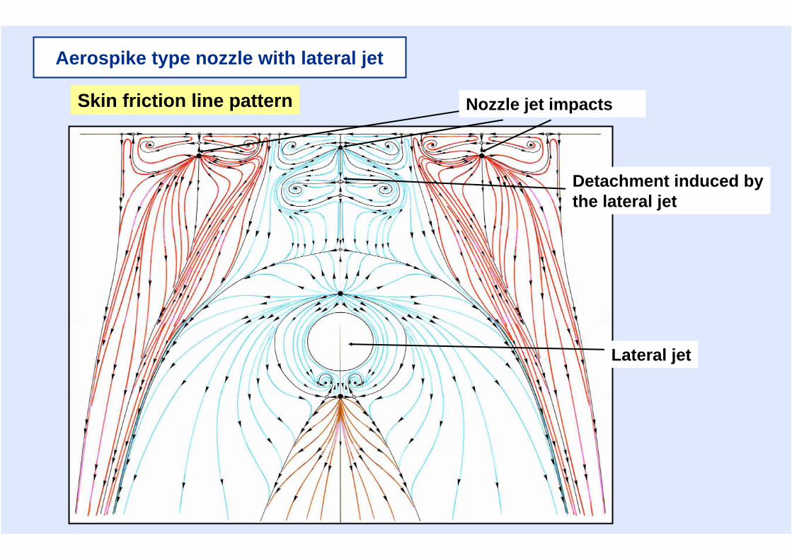
Aerospike type nozzle with lateral jet
Lateral jet
Detachment induced bythe lateral jet
Nozzle jet impactsSkin friction line pattern
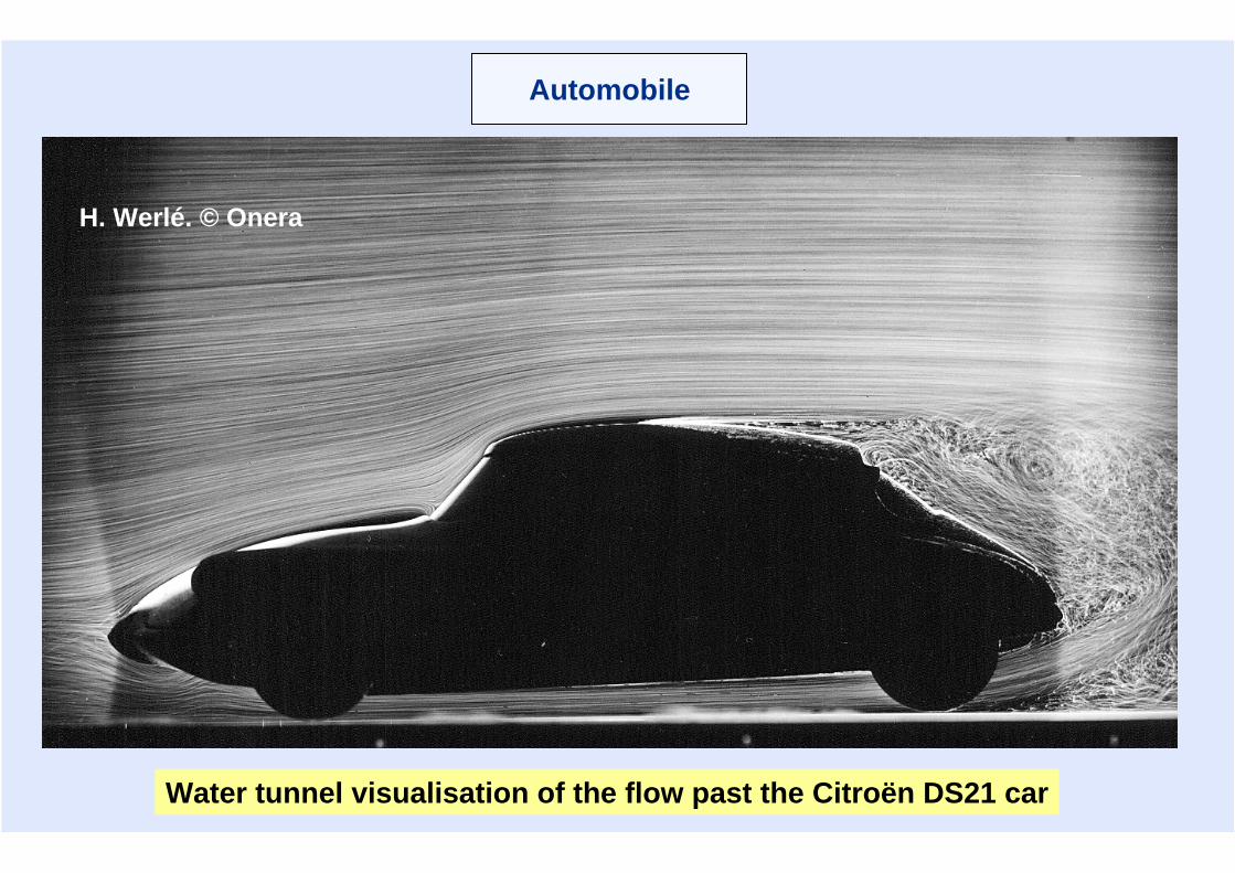
Automobile
H. Werlé. © Onera
Water tunnel visualisation of the flow past the Citroën DS21 car
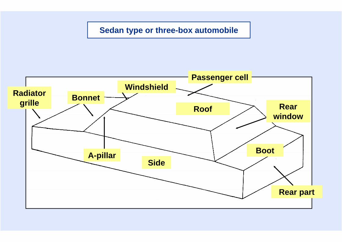
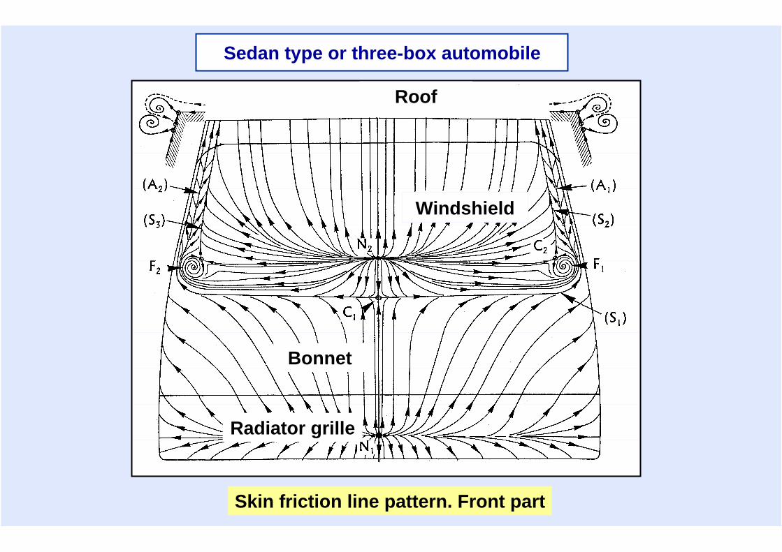
Sedan type or three-box automobile
Passenger cellWindshield
RoofBonnet
SideBoot
Rear part
Rear window
A-pillar
Radiatorgrille
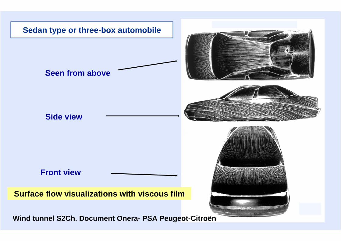
Surface flow visualizations with viscous film
Seen from above
Side view
Front view
Wind tunnel S2Ch. Document Onera- PSA Peugeot-Citroën
Sedan type or three-box automobile
Roof
Windshield
Bonnet
Radiator grille
Skin friction line pattern. Front part
Sedan type or three-box automobile
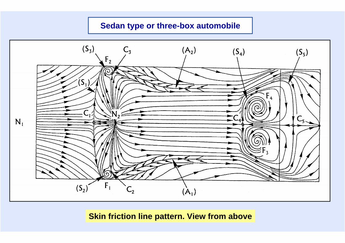
Skin friction line pattern. View from above
Sedan type or three-box automobile
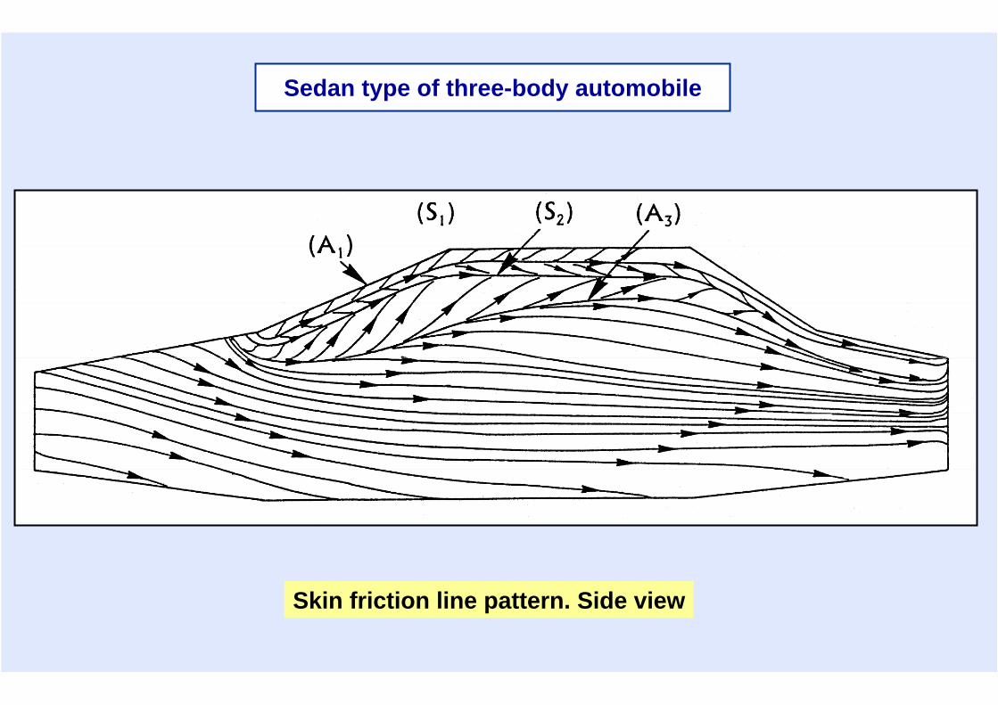
Skin friction line pattern. Side view
Sedan type of three-body automobile
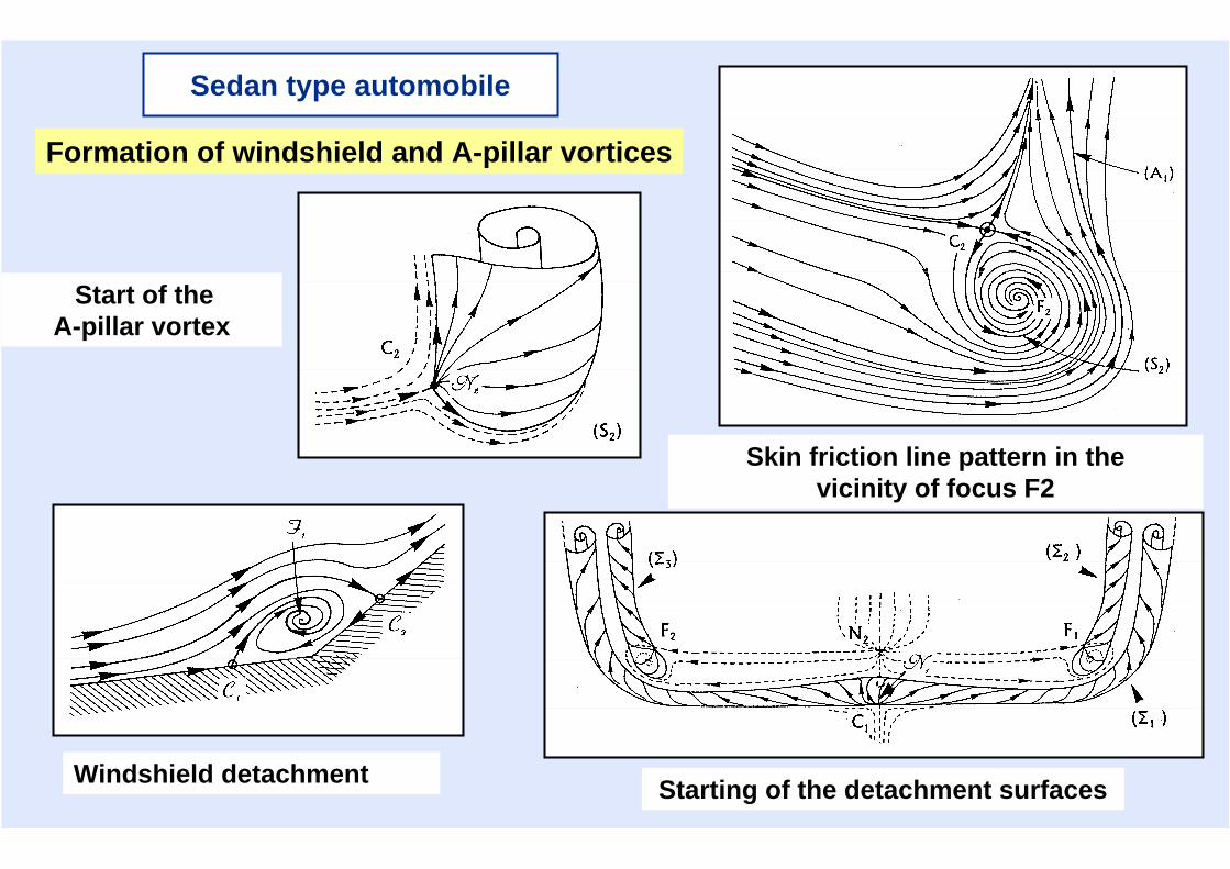
Sedan type automobile
Skin friction line pattern in thevicinity of focus F2
Start of theA-pillar vortex
Windshield detachment Starting of the detachment surfaces
Formation of windshield and A-pillar vortices
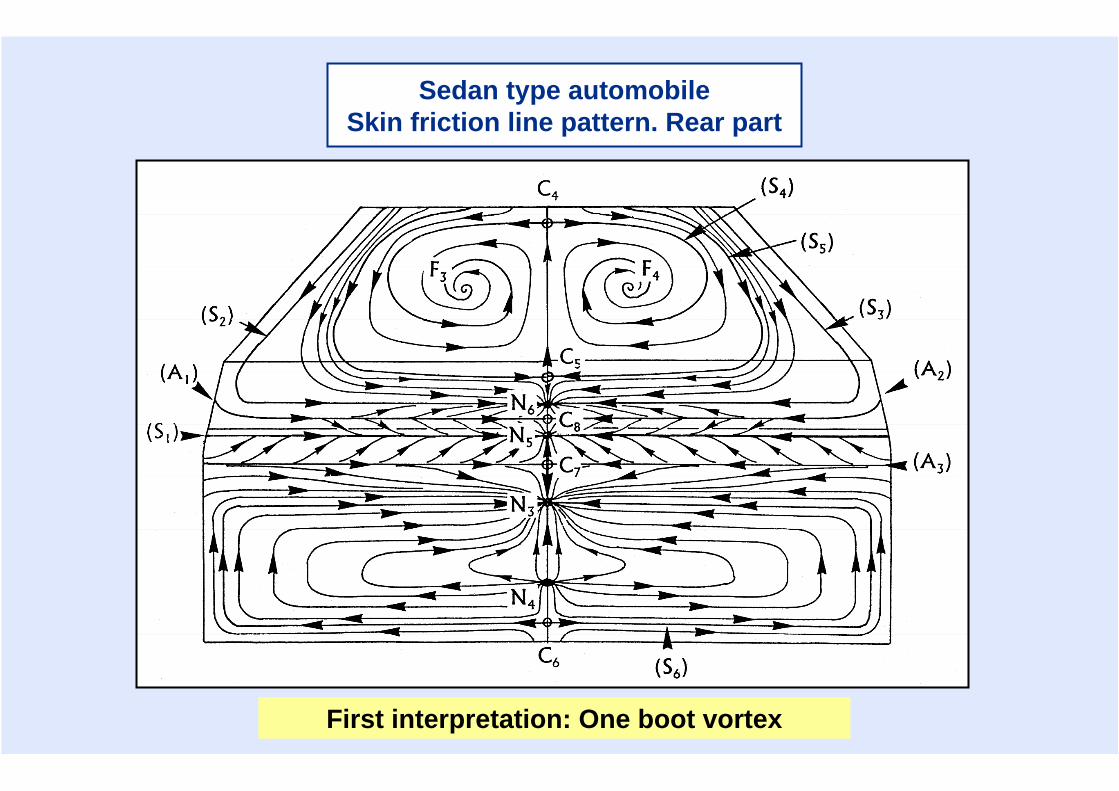
Sedan type automobileSkin friction line pattern. Rear part
First interpretation: One boot vortex
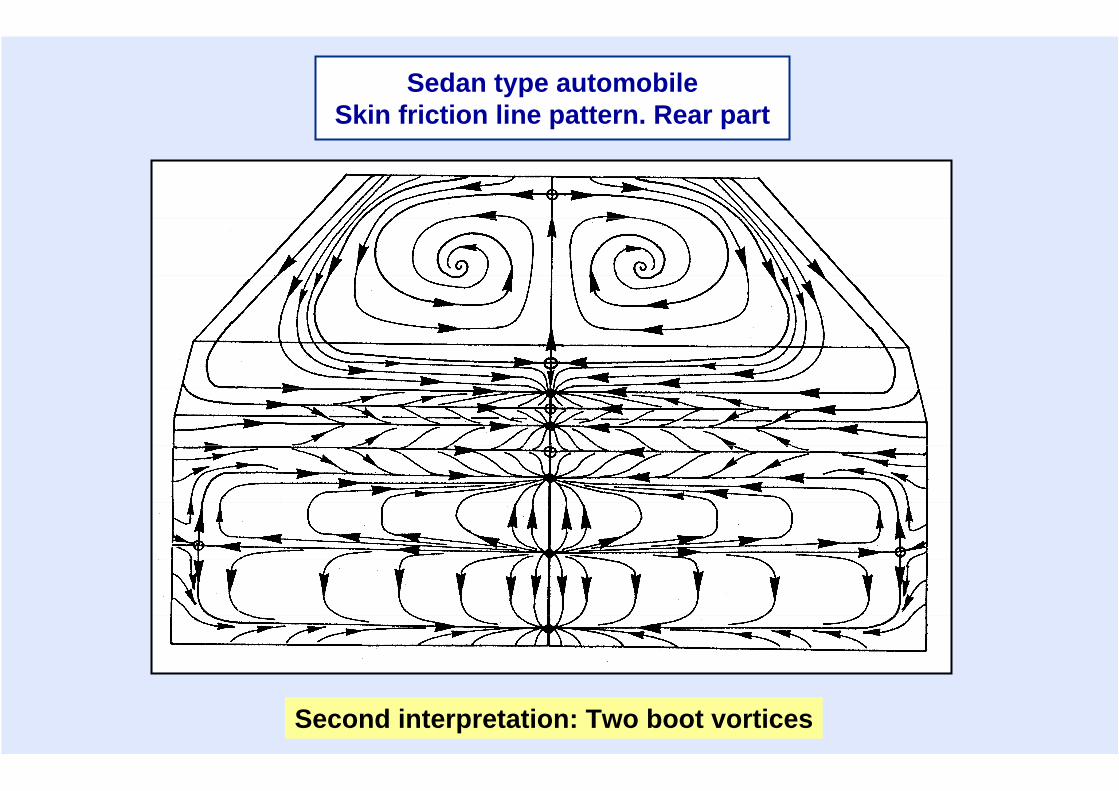
Second interpretation: Two boot vortices
Sedan type automobileSkin friction line pattern. Rear part
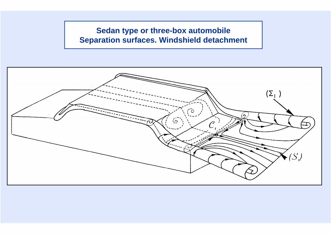
Sedan type or three-box automobileSeparation surfaces. Windshield detachment
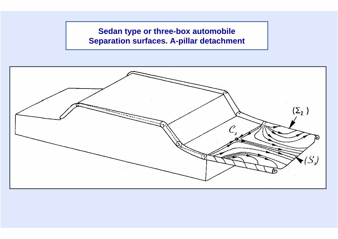
Sedan type or three-box automobileSeparation surfaces. A-pillar detachment
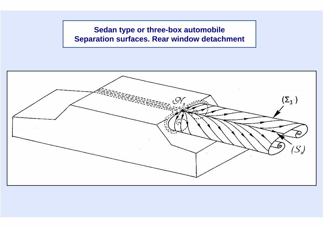
Sedan type or three-box automobileSeparation surfaces. Rear window detachment
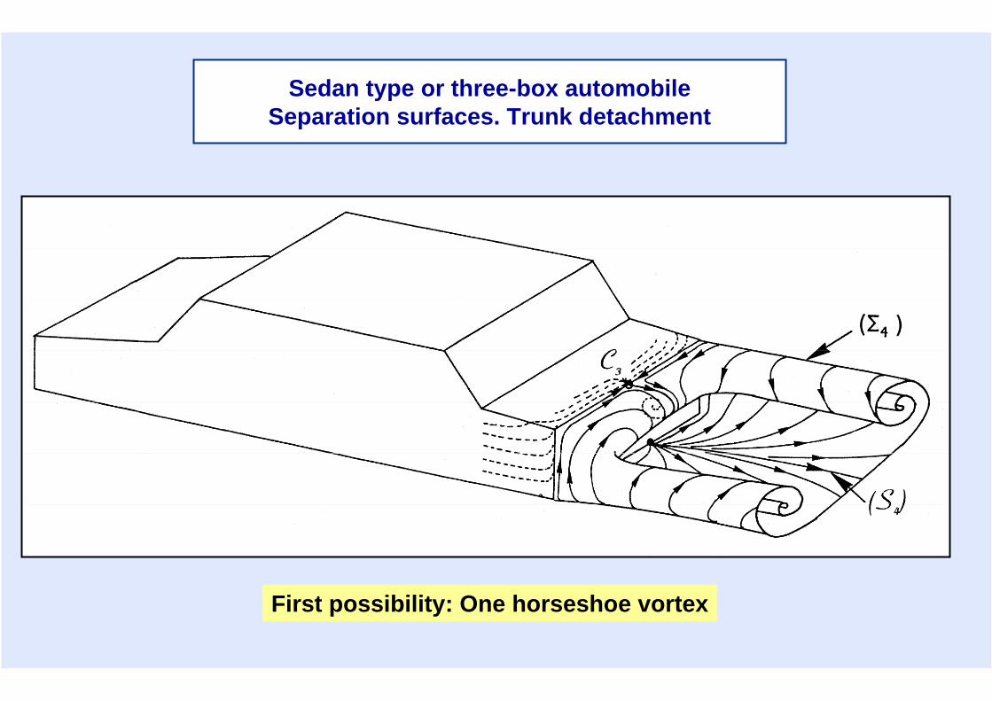
First possibility: One horseshoe vortex
Sedan type or three-box automobileSeparation surfaces. Trunk detachment
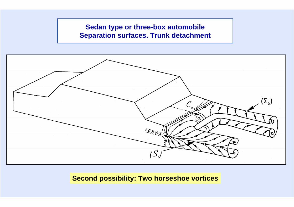
Second possibility: Two horseshoe vortices
Sedan type or three-box automobileSeparation surfaces. Trunk detachment
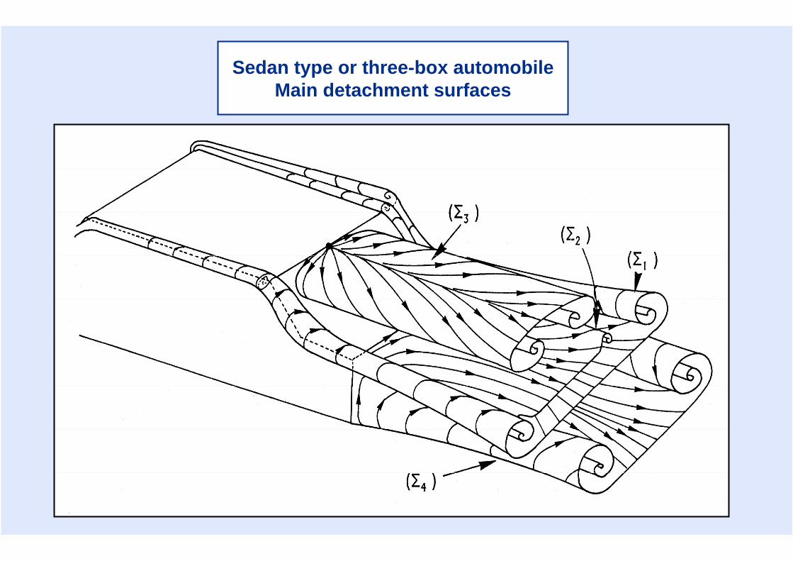
Sedan type or three-box automobileMain detachment surfaces
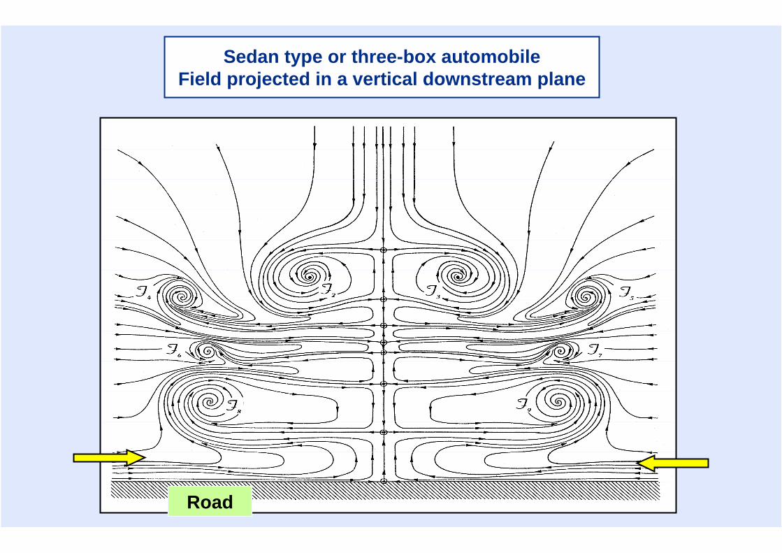
Sedan type or three-box automobileField projected in a vertical downstream plane
Road