Embed Size (px)
Citation preview
Part 2: Software Defined Radios
April 2002 COTS Journal [ 13 ]
T he Joint Tactical Radio System(JTRS), a program to develop afamily of software defined radios to
meet the tactical needs of the ArmedServices, incorporates several phases. InJanuary 2002, Part 1 of this articledescribed in detail the prototyping andvalidation activities undertaken in Step2A (COTS Journal, January 2002, page40). Now, let’s focus on Step 2B activities.
The JTRS Step 2B agreements provid-ed for additional, third-party validation ofthe program’s Software CommunicationsArchitecture (SCA) and additional studiesof high interest to the tactical radio com-munity. In total, seven Step 2B agreementswere awarded to Assurance TechnologyCorporation (ATC), Boeing, GeneralDynamics Decision Systems (formerlyMotorola), Harris, Rockwell Collins,Thales (formerly Racal) and Vanu.
Assurance TechnologyCorporation
The intent of the AssuranceTechnology Corporation 2B agreement isto validate the SCA by developing a wave-
form independent of the hardware. ATC isimplementing a Single Channel Groundand Airborne Radio System (SINCGARS)Enhanced System Improvement Program(ESIP) waveform, including an INC(Internet Controller) that is used in theArmy networking structure as a router.Their version of SINCGARS ESIP, whichwill be SCA v2.0-compliant, will be license-free to the government and uses the modesof MIL-STD-188-220. They are also devel-oping a JTRS test suite that includes thecapability to inject external stimuli and ameasurement capability to validate func-tional performance. ATC successfullydemonstrated the basic single channel,plain text mode in May 2001. This effort ison track for completion in August 2002.
ATC’s development work has takenplace in a Windows environment becauseof the feeling that this platform had amore mature set of development andtesting tools. Their operating environ-ment includes the LynxOS Real-TimeOperating System, the ACE ORB (TAO)and Objective Interface Systems’ (OIS)ORBexpress ORB for Ada 95. They origi-nally began using Adabroker, an opensource CORBA ORB for Ada 95, but ithad memory leak issues. They also use
tools by Epilogue, Rational Rose, andNuThena (Foresight).
Their JTRS “test bed” is a 1 GHz IntelPentium with 256 Mbytes of memoryusing a PCI bus, a Trimble Force 22 GPScard and a modem card. The I/O inter-face uses Ethernet to the INC as well as tothe modem. The GPS card interfaces tothe processor using RS232 and sends its 1PPS to the modem using RS422. An addi-tional part of this effort is to port thewaveform to the Raytheon-developedValidation Development Model (VDM).
Boeing The Step 2B agreement with Boeing
was to develop a Core Framework middle-ware, independent of the Step 2A compa-nies, which provided a government limit-ed-purpose community license. Boeinghad a strategy to maximize the use ofCOTS hardware in its development and touse standard signal processing libraries toenhance modem software portability. Theoperating environment used by Boeingconsisted of ORBexpress RT by OIS,VxWorks by WindRiver and PowerPCmodules in a CompactPCI chassis.
Validation of their SCA v2.0-com-pliant Core Framework implementation
Softer SideOn The
Dawn Szelc, Lead EngineerThe MITRE Corporation
Prototyping and Validation Using COTSfor Military Software Defined RadioSystems, Part 2
The Joint Tactical Radio System’s Joint Program Office has the mission to developa family of software defined radios to meet the tactical needs of the Armed Services.Part 1 looked at the results of Step 2A contracts to develop and validate an archi-tecture. Now, Part 2 examines the results of Step 2B, which provided additionalvalidation of the architecture as well as prototypes of certain high-risk elements.
For
Re
pri
nt
Ord
ers
Cal
l (9
49
)22
6-2
00
0 /
©2
00
2 T
he
RTC
Gro
up
was done on a Boeing-developed test bedwith a test waveform. They analyzed sys-tem integration issues and delivered bothan airborne platform integration studyand plug-and-play study to the JPO.These were used by the DOD’s JointService Working Group to support pro-gram execution. The Core Framework
source code and documentation wasdelivered to the JPO in December 2001.
General Dynamics DecisionSystems
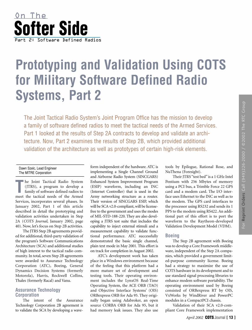
A 2B agreement was awarded toGeneral Dynamics to evaluate the impactof the SCA on their Digital ModularRadio (DMR), a software radio developedfor a Navy contract (Figure 1). The DMRis intended to be an interim solution tosolve near-term Navy requirements. Itssoftware architecture is similar to the SCAin that it uses Common Object RequestBroker Architecture (CORBA) as themessage-passing technology and anobject-oriented middleware.
DMR is not SCA-compliant since itsdevelopment began before the release ofthe SCA. Step 2B activities included proto-typing SCA v1.0-complaint DMR subsys-tem software modifications and infrastruc-ture upgrades. The platform–supportedwaveforms were analyzed to determinewhat modifications would be required tomake them SCA-compliant. Waveformcoverage included non-secure AM/FMline-of-sight (LOS). General Dynamicsalso participated in the ConfigurationControl Board that reviews proposals toupdate the SCA. General Dynamics is justcompleting work on an extension to pro-vide a feasibility study to assess the conver-
sion of DMR to SCA v2.0+ complianceand a Compliance Test RequirementsDocument that proposes a test process forJTRS set and waveform SCA compliance.
Harris The original 2B agreement with
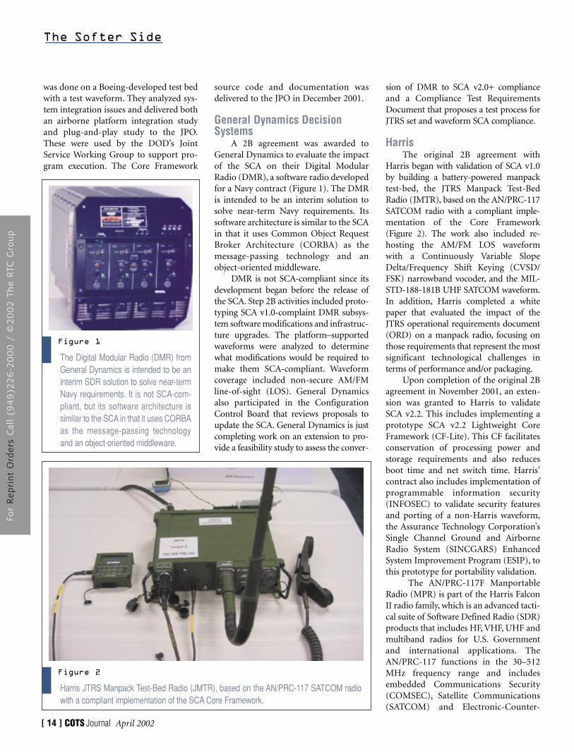
Harris began with validation of SCA v1.0by building a battery-powered manpacktest-bed, the JTRS Manpack Test-BedRadio (JMTR), based on the AN/PRC-117SATCOM radio with a compliant imple-mentation of the Core Framework (Figure 2). The work also included re-hosting the AM/FM LOS waveform with a Continuously Variable SlopeDelta/Frequency Shift Keying (CVSD/FSK) narrowband vocoder, and the MIL-STD-188-181B UHF SATCOM waveform.In addition, Harris completed a whitepaper that evaluated the impact of theJTRS operational requirements document(ORD) on a manpack radio, focusing onthose requirements that represent the mostsignificant technological challenges interms of performance and/or packaging.
Upon completion of the original 2Bagreement in November 2001, an exten-sion was granted to Harris to validateSCA v2.2. This includes implementing aprototype SCA v2.2 Lightweight CoreFramework (CF-Lite). This CF facilitatesconservation of processing power andstorage requirements and also reducesboot time and net switch time. Harris’contract also includes implementation ofprogrammable information security(INFOSEC) to validate security featuresand porting of a non-Harris waveform,the Assurance Technology Corporation’sSingle Channel Ground and AirborneRadio System (SINCGARS) EnhancedSystem Improvement Program (ESIP), tothis prototype for portability validation.
The AN/PRC-117F ManportableRadio (MPR) is part of the Harris FalconII radio family, which is an advanced tacti-cal suite of Software Defined Radio (SDR)products that includes HF, VHF, UHF andmultiband radios for U.S. Governmentand international applications. TheAN/PRC-117 functions in the 30–512MHz frequency range and includesembedded Communications Security(COMSEC), Satellite Communications(SATCOM) and Electronic-Counter-
The Softer Side
[ 14 ] COTS Journal April 2002
The Digital Modular Radio (DMR) fromGeneral Dynamics is intended to be aninterim SDR solution to solve near-termNavy requirements. It is not SCA-com-pliant, but its software architecture issimilar to the SCA in that it uses CORBAas the message-passing technologyand an object-oriented middleware.
Figure 1
Harris JTRS Manpack Test-Bed Radio (JMTR), based on the AN/PRC-117 SATCOM radiowith a compliant implementation of the SCA Core Framework.
Figure 2
For
Re
pri
nt
Ord
ers
Cal
l (9
49
)22
6-2
00
0 /
©2
00
2 T
he
RTC
Gro
up
Counter-Measure (ECCM) capabilities. Itsupports multi-mode operations for bothLOS and UHF Tactical Satellite missions.
The principal hardware modules inthe JMTR are a black-side processor con-taining an MPC860 PowerPC controlprocessor, a TMS320C548 DSP, a controlFPGA and a digital IF up- and down-con-verter. A red-side module contains aTMS320C548 DSP as well as an FPGA. ASATCOM communications module alsocontains a TMS320C548 DSP and anFPGA. On the RF side, the JMTR includesa Multiband Receiver/Exciter/Synthesizermodule, a VHF Power Amplifier and aUHF Power Amplifier.
The operating environment used byHarris consists of ORBexpress by ObjectiveInterface Systems (OIS) and the VxWorksreal-time operating system (RTOS) fromWind River. It also includes the DomainManager Run-Time Environment (DMRE)from Exigent International, now part ofHarris, for the Domain Management por-tion of the Core Framework.
The black-side processor executesthe Core Framework, the waveformapplication software and the Human-Machine Interface (HMI) and includes aDSP that performs the modem process-ing. The red-side processor provides thevocoder functionality. A third DSP pro-vides additional capability for modem
processing for stressing waveforms. Bothwaveforms, the LOS with CVSD andUHF SATCOM, were demonstratedusing the JMTR and are interoperablewith the existing AN/PRC-117.
For the extension, the hardwareupgrades include an increase in processingpower, the addition of a red-side general-purpose processor and removal of a cus-tom ASIC for front-end processing. Thefront-end processing will be done in a DSPand an FPGA. The RF hardware will beused as is and the INFOSEC will be a pro-grammable Harris Sierra II chip designedas a daughter-board. Harris is currentlyevaluating VxWorks, HardHat Linux,LynxOS, and QNX for the RTOS. For theORB implementation they are looking atORBexpress from OIS as well as ACE/TAOfrom Washington University, St Louis.This effort extends until October 2003.
Rockwell Collins The Rockwell Collins’ 2B agreement
was to prototype portions of the Link-16waveform as a risk reduction activity. Thiseffort was intended to validate that an SCAv1.0 software radio can support the Link-16 waveform, reducing the risks of thefuture Link-16 implementation. Rockwellvalidated critical aspects of the waveformsuch as timing and latency requirementsusing OPNET and reviewed processor
loading. Other activities included modelingand waveform simulation in both a stand-alone and a multi-waveform environmentand the development of a hardware proto-type radio capable of supporting Link-16and other waveforms. A Simultaneity TestTool was developed to provide a multi-waveform environment for this effort.
The modeling and simulation resultsshowed that bus bandwidth requirementsand system latencies were acceptable withreserve capacity available in both cases.Both PCI and VME bus modeling weredone as well as a bridge bus between the red and black processing sides.Additionally, Rockwell looked at the la-tency of the CORBA ORB transport overVMEbus. Although the actual delay wasunknown, they incrementally increased thevalue until a waveform failure was de-tected. In this way, an upper limit on trans-port delay due to the ORB was identified.
Rockwell delivered APIs for Link-16in Interface Definition Language (IDL) tothe JTRS Joint Program Office (JPO) aswell as a cost analysis for “Link-16, LessonsLearned about the SCA”, a report on secu-rity impact to the SCA from implementingLink-16 and spectrum issues associatedwith Link-16. This effort was completed inSeptember 2001, but an extension to theagreement continued the analysis for SCAv2.0 through March 2002.
Thales As a current provider of handheld
military radios, Thales (formerly Racal)proposed a 2B handheld prototype basedon their current Multiband Inter/IntraTeam Radio (MBITR). This was devel-oped for the U.S. Special OperationsForces and operates at 30-512 MHz usingAM/FM voice and data. It also includesan embedded cryptographic function.
Thales proposed validating the SCAby modifying the processor architecture inthe MBITR to include the SCA CoreFramework. They used adapters to providean interface between their current security,modem and host command interface(HCI) classes and the Core FrameworkServices. They also used adapters for theircurrent implementation of the AM/FMwaveform application. The operating envi-ronment consists of VxWorks 5.4 fromWindRiver, ORBexpress 2.3.1 from OIS,
The Softer Side
[ 16 ] COTS Journal April 2002
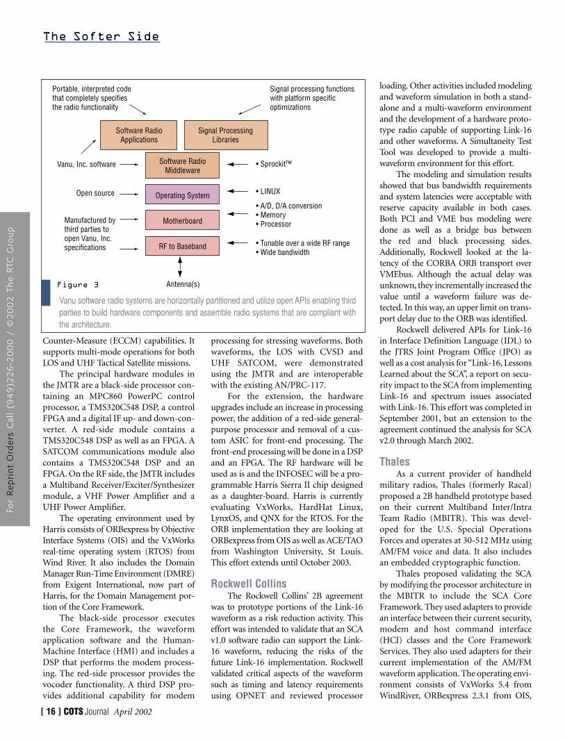
Vanu software radio systems are horizontally partitioned and utilize open APIs enabling thirdparties to build hardware components and assemble radio systems that are compliant withthe architecture.
Figure 3
Portable, interpreted codethat completely specifiesthe radio functionality
Manufactured bythird parties toopen Vanu, Inc.specifications
• Sprockit™
• LINUX
• A/D, D/A conversion• Memory• Processor
• Tunable over a wide RF range• Wide bandwidth
Signal processing functionswith platform specificoptimizations
Antenna(s)
Software RadioApplications
Signal ProcessingLibraries
Software RadioMiddleware
Operating System
Motherboard
RF to Baseband
Vanu, Inc. software
Open source
For
Re
pri
nt
Ord
ers
Cal
l (9
49
)22
6-2
00
0 /
©2
00
2 T
he
RTC
Gro
up
and the Core Framework developed byRaytheon in Step 2A.
The baseline MBITR handheld usedthree main processors, a black and a redDSP (both ADSP-2189s), and a HitachiH8/300H processor used for control func-tions. The Hitachi processor and the redDSP were replaced with a 32-bit general-purpose processor, the StrongARM SA-1110. The StrongARM is optimized forportable and embedded applications andhas enough processing power for both func-tions. The black DSP approach was retainedfor implementing most of the waveformfunctionality in software even though this isnot easily portable to other platforms.
Later this agreement was modified toinclude a new TI DSP, the TMS320C55x,in place of the current DSP. This new DSPhas significantly lower power consump-tion and improved heat dissipation. Also,it provides a standard set of coding con-ventions and applications programminginterfaces (APIs) for use by algorithm cre-ators. This allows a developer to “wrap”the algorithm for system-ready use.
Thales has an additional extension tothis agreement to upgrade the CoreFramework to SCA v2.2. Additionally,they are required to implement a stressingwaveform that will be a variation ofSINCGARS and possibly to replace theexisting embedded crypto with a pro-grammable embedded crypto that is fullycompliant with the Security Supplementof the SCA. This extension takes the cur-rent agreement through February of 2003.
VanuThe Vanu activity for Step 2B in-
cluded evaluations of SCA v1.0 and v2.0,examination of variants of the SCA forthe handheld domain, design and build-ing of a prototype handheld radio andevaluation of the prototype radio’s per-formance. Vanu has completed a numberof documents evaluating the SCA duringits evolution, including: “PreliminaryEvaluation of SCA 1.0 with respect to theHandheld Radio Domain”, “CurrentEvaluation of JTRS SCA v1.1 and “JTRSSRD v1.1” and “Evaluation of JTRS SCA2.0”. Vanu also did a study for JTRS of theuse of CORBA as the middleware mes-sage-passing technique versus standardmessage-passing techniques and the
benchmarking of five different legacywaveforms on three different processorsgenerally used in handheld radios. Theyalso did a comparative evaluation ofnumerous software radio architectures.
Vanu designed and built a prototypehandheld radio (Figure 3). It utilizes aniPAQ PDA from Compaq for the userinterface with the software radio plug-ging in to the PDA’s expansion port. Theradio frequency (RF) front end consistsof antenna(s) and a RF-to-baseband con-version section that will be purchased asCOTS equipment. Additionally, there is amotherboard that contains the A/D andD/A conversion sections as well as anIntel StrongARM SA-1110 processor withmemory and I/O. Linux was utilized asthe operating system. Vanu used theirSprockit runtime toolkit for the softwareradio middleware layer, enabling applica-tions to be constructed from a library ofsignal processing modules and handlingall of the I/O between modules.
The waveforms benchmarked werethe voice and control channels forAdvanced Mobile Phone Service (AMPS)cellular radio, the Mobitex physical layer,Code Division Multiple Access (CDMA)IS-95 spreading and de-spreading, a fre-quency hopping system, the InternetController (INC) associated with SINC-GARS and, finally, legacy AM and FMradio systems. This effort continuedthrough the end of December 2001.
There have been many successfuldevelopments for the JTRS program inboth Steps 2A and 2B. At this point, theSoftware Communications Architectureis fairly mature and will continue toevolve with the program. Numerous pro-totype efforts have validated this archi-tecture and proven the possibility of suc-cessful waveform and hardware unitdevelopment. Extensions of Step 2B workcontinue through October 2003.
The MITRE CorporationMcLean, VA.(703) 883-6000.[www.mitre.org].
Assurance Technology CorporationCarlisle, MA.(978) 369-8848.[www.assurtech.com].
BoeingSeattle WA.(206) 655-1131.[www.boeing.com].
General Dynamics Decision Systems(formerly Motorola)Scottsdale, AZ.(877) 449-0600.[www.gd-decisionsystems.com].
Harris (formerly Exigent International)Melbourne, FL.(321) 727-9100.[www.govcomm.harris.com].
HarrisRochester, NY.(716) 244-5830.[www.harris.com].
Joint Tactical Radio System (JTRS)[www.jtrs.saalt.army.mil].
Objective Interface Systems (OIS)Herndon, VA.(703) 295-6500.[www.ois.com].
RaytheonFort Wayne, IN.(219) 429-7714.[www.raytheon.com].
Rockwell Collins Government SystemsCedar Rapids, IA.(319) 295-1000.[www.collins.rockwell.com].
Thales Communications (formerly RacalCommunications)Clarksburg, MD.(240) 864-7000.[www.racalcomm.com].
VanuCambridge, MA.(617) 864-1711.[www.vanu.com].
Wind River SystemsAlameda, CA.(510) 748-4100.[www.windriver.com].
The Softer Side
April 2002 COTS Journal [ 17 ]
For
Re
pri
nt
Ord
ers
Cal
l (9
49
)22
6-2
00
0 /
©2
00
2 T
he
RTC
Gro
up
Part 2: Software Defined Radios
April 2002 COTS Journal [ 19 ]
T here have been significant advancesin Software Radio over the past fewyears. Improvements in high-speed,
high-bit-count analog-to-digital convert-ers (ADCs) and digital-to-analog converters (DACs) have fueled theseadvances. Increases in the processingcapacities of PC processors have enabledsignificant amounts of base band processing to be handled by general-purpose PC processors. However, gener-ating reproducible and well-behaved testsignals for communication systems isoften an expensive and cumbersomeproposition.
Commercially available test equip-ment may not offer the flexibilityrequired to customize a test. However, itcan be demonstrated that a Code
Division Multiple Access (CDMA) 1.2288Mchip/s transmitter can be implementedin a PC by using COTS digital-to-analogcards, the processing power of the PC andthe MATLAB programming language.Using a 1 GHz Pentium, the unoptimizedprocessing time is estimated to be 40 msper CDMA frame. This includes thePseudo Random number (PN) sequencegeneration time and is thus a conserva-tive estimate. It is also believed that fur-ther optimization of the code will lead toreduced processing time. The commercialDAC used in the test can handle updaterates over 65 MHz.
The ModelThe CDMA2000 standard for 3G
wireless systems specifies various types ofradio configurations (RCs) to suit differ-ent users and operators’ requirements.Nine different RCs have been defined inthe standard (Physical Layer Standard forCDMA2000 Spread Spectrum System.3GPP2 C.S0002, Version 3.0, June 15,
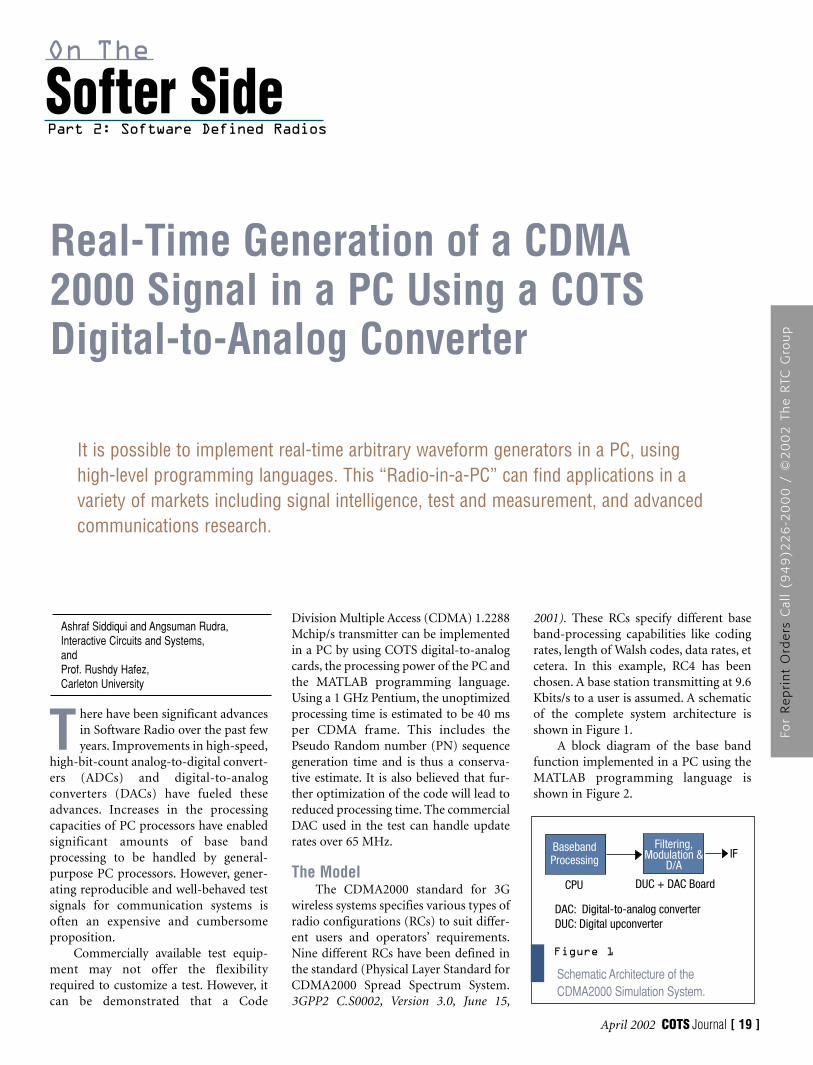
2001). These RCs specify different baseband-processing capabilities like codingrates, length of Walsh codes, data rates, etcetera. In this example, RC4 has beenchosen. A base station transmitting at 9.6Kbits/s to a user is assumed. A schematicof the complete system architecture isshown in Figure 1.
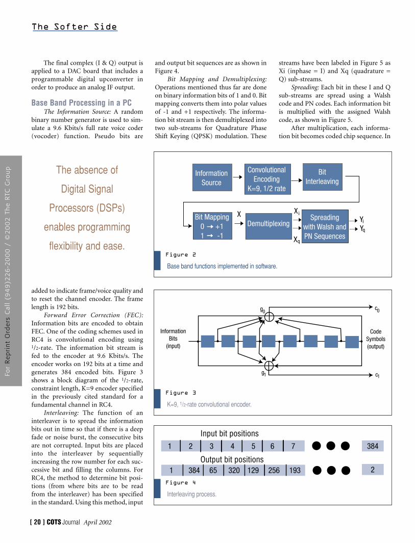
A block diagram of the base bandfunction implemented in a PC using theMATLAB programming language isshown in Figure 2.
Softer SideOn The
Ashraf Siddiqui and Angsuman Rudra,Interactive Circuits and Systems, andProf. Rushdy Hafez,Carleton University
Real-Time Generation of a CDMA2000 Signal in a PC Using a COTSDigital-to-Analog Converter
It is possible to implement real-time arbitrary waveform generators in a PC, usinghigh-level programming languages. This “Radio-in-a-PC” can find applications in avariety of markets including signal intelligence, test and measurement, and advancedcommunications research.
Schematic Architecture of theCDMA2000 Simulation System.
Figure 1
BasebandProcessing
Filtering,Modulation &
D/A
CPU DUC + DAC Board
DAC: Digital-to-analog converterDUC: Digital upconverter
IF
For
Re
pri
nt
Ord
ers
Cal
l (9
49
)22
6-2
00
0 /
©2
00
2 T
he
RTC
Gro
up
and output bit sequences are as shown inFigure 4.
Bit Mapping and Demultiplexing:Operations mentioned thus far are doneon binary information bits of 1 and 0. Bitmapping converts them into polar valuesof -1 and +1 respectively. The informa-tion bit stream is then demultiplexed intotwo sub-streams for Quadrature PhaseShift Keying (QPSK) modulation. These
The final complex (I & Q) output isapplied to a DAC board that includes aprogrammable digital upconverter inorder to produce an analog IF output.
Base Band Processing in a PCThe Information Source: A random
binary number generator is used to sim-ulate a 9.6 Kbits/s full rate voice coder(vocoder) function. Pseudo bits are
added to indicate frame/voice quality andto reset the channel encoder. The framelength is 192 bits.
Forward Error Correction (FEC):Information bits are encoded to obtainFEC. One of the coding schemes used inRC4 is convolutional encoding using 1/2-rate. The information bit stream isfed to the encoder at 9.6 Kbits/s. Theencoder works on 192 bits at a time andgenerates 384 encoded bits. Figure 3shows a block diagram of the 1/2-rate,constraint length, K=9 encoder specifiedin the previously cited standard for afundamental channel in RC4.
Interleaving: The function of aninterleaver is to spread the informationbits out in time so that if there is a deepfade or noise burst, the consecutive bitsare not corrupted. Input bits are placedinto the interleaver by sequentiallyincreasing the row number for each suc-cessive bit and filling the columns. ForRC4, the method to determine bit posi-tions (from where bits are to be readfrom the interleaver) has been specifiedin the standard. Using this method, input
streams have been labeled in Figure 5 asXi (inphase = I) and Xq (quadrature =Q) sub-streams.
Spreading: Each bit in these I and Qsub-streams are spread using a Walshcode and PN codes. Each information bitis multiplied with the assigned Walshcode, as shown in Figure 5.
After multiplication, each informa-tion bit becomes coded chip sequence. In
The Softer Side
[ 20 ] COTS Journal April 2002
K=9, 1/2-rate convolutional encoder.
Figure 3
InformationBits
(input)
CodeSymbols(output)
cg
g0
1
c0
1
Interleaving process.
Figure 4
1 2 3 4 5 6 7
1 384 65 320 129 256 193
384
2
Input bit positions
Output bit positions
The absence of
Digital Signal
Processors (DSPs)
enables programming
flexibility and ease.
Base band functions implemented in software.
Figure 2
InformationSource
ConvolutionalEncoding
K=9, 1/2 rate
BitInterleaving
Bit Mapping0 +1 1 -1
DemultiplexingSpreading
with Walsh andPN Sequences
X X
X
YY
i
q
i
q
For
Re
pri
nt
Ord
ers
Cal
l (9
49
)22
6-2
00
0 /
©2
00
2 T
he
RTC
Gro
up
the previously cited reference, a Walshcode with a length of 128 chips is usedfor RC4. So, each information bit isspread in 128 chips. The resultant I andQ sequences are further multiplied withPN sequences using a complex multipli-er and called I and Q PN sequences.These are used to identify the base sta-tions in the system. These PN sequencesare periodic and generated using shiftregisters. The Walsh code spreading leadsto an increased chip rate, while the PNspreading does not lead to an increase inchip rate.
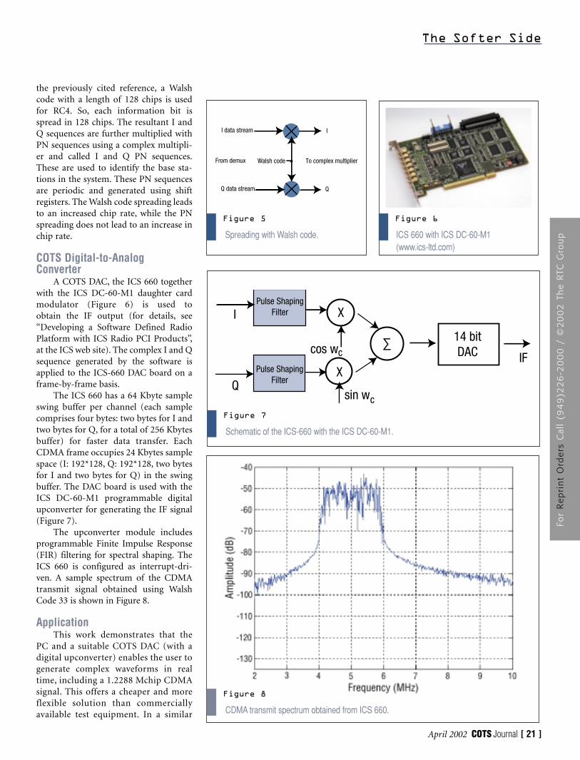
COTS Digital-to-AnalogConverter
A COTS DAC, the ICS 660 togetherwith the ICS DC-60-M1 daughter cardmodulator (Figure 6) is used to obtain the IF output (for details, see“Developing a Software Defined RadioPlatform with ICS Radio PCI Products”,at the ICS web site). The complex I and Qsequence generated by the software isapplied to the ICS-660 DAC board on aframe-by-frame basis.
The ICS 660 has a 64 Kbyte sampleswing buffer per channel (each samplecomprises four bytes: two bytes for I andtwo bytes for Q, for a total of 256 Kbytesbuffer) for faster data transfer. EachCDMA frame occupies 24 Kbytes samplespace (I: 192*128, Q: 192*128, two bytesfor I and two bytes for Q) in the swingbuffer. The DAC board is used with theICS DC-60-M1 programmable digitalupconverter for generating the IF signal(Figure 7).
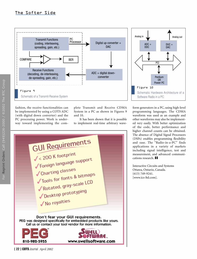
The upconverter module includesprogrammable Finite Impulse Response(FIR) filtering for spectral shaping. TheICS 660 is configured as interrupt-dri-ven. A sample spectrum of the CDMAtransmit signal obtained using WalshCode 33 is shown in Figure 8.
ApplicationThis work demonstrates that the
PC and a suitable COTS DAC (with adigital upconverter) enables the user togenerate complex waveforms in realtime, including a 1.2288 Mchip CDMAsignal. This offers a cheaper and moreflexible solution than commerciallyavailable test equipment. In a similar
The Softer Side
April 2002 COTS Journal [ 21 ]
ICS 660 with ICS DC-60-M1(www.ics-ltd.com)
Figure 6
Spreading with Walsh code.
Figure 5
I data stream
Walsh code
Q data stream
I
Q
To complex multiplierFrom demux
Schematic of the ICS-660 with the ICS DC-60-M1.
Figure 7
I
Q
X
X
∑ 14 bitDAC IF
sin wc
cos wc
Pulse ShapingFilter
Pulse ShapingFilter
CDMA transmit spectrum obtained from ICS 660.
Figure 8
For
Re
pri
nt
Ord
ers
Cal
l (9
49
)22
6-2
00
0 /
©2
00
2 T
he
RTC
Gro
up
The Softer Side
[ 22 ] COTS Journal April 2002
fashion, the receive functionalities canbe implemented by using a COTS ADC(with digital down converter) and thePC processing power. Work is under-way toward implementing the com-
plete Transmit and Receive CDMASystem in a PC as shown in Figures 9and 10.
It has been shown that it is possibleto implement real-time arbitrary wave-
form generators in a PC, using high-levelprogramming languages. The CDMAwaveform was used as an example andother waveforms may also be implement-ed very easily. With better optimizationof the code, better performance andhigher channel counts can be obtained.The absence of Digital Signal Processors(DSPs) enables programming flexibilityand ease. The “Radio-in-a-PC” findsapplications in a variety of marketsincluding signal intelligence, test andmeasurement, and advanced communi-cations research.
Interactive Circuits and SystemsOttawa, Ontario, Canada.(613) 749-9241.[www.ics-ltd.com].
Schematic of a Transmit-Receive System
Figure 9
Transmit Functions(coding, interleaving,spreading, gain, etc.)
Receive Functions(decoding, de-interleaving,de-spreading, gain, etc.)
Digital up converter +DAC
ADC + digital down-converter
BERCOMPARE
PCProcessor
Schematic Hardware Architecture of aSoftware Radio in a PC
Figure 10
PCI
ADC +DDC
DUC +DAC
PentiumOR
Power PC
Analog outAnalog in
For
Re
pri
nt
Ord
ers
Cal
l (9
49
)22
6-2
00
0 /
©2
00
2 T
he
RTC
Gro
up
Part 2: Software Defined Radios
Current software defined radio(SDR) programs and research forthe Department of Defense (DoD)
are focused on delivering an early set ofcapabilities to the field. SDR offers apromise of virtually unlimited flexibilityin providing the glue that connects oldand new generations of radio systems.With the lure of more than 180,000 sys-tems as the prize, almost everyone in thevendor community is rushing to be therefirst. What bothers some system archi-tects is that vendors may be overlookinga serious bottleneck to the next step.
The bottleneck raises its ugly headwhen one sees increasing levels of co-siteand co-channel interference as these newradios proliferate. Computer and soft-ware architectures, which work well forindividual systems, may fail when con-fronted by a system with multiple radiossimultaneously operating in networks.This is especially true when multipleradios operate on small platforms such asaircraft and combat vehicles. Techniquessuch as adaptive beam forming andwaveform-specific interference cancella-tion demand a quantum jump in soft-ware-reconfigurable processing power.The “hooks” for the jump must be inplace from the start.
Behind the Promise LiesComplexity
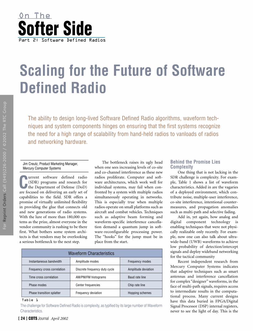
One thing that is not lacking in theSDR challenge is complexity. For exam-ple, Table 1 shows a list of waveformcharacteristics. Added in are the vagariesof a deployed environment, which con-tribute noise, multiple-user interference,co-site interference, intentional counter-measures, and propagation anomaliessuch as multi-path and selective fading.
Add in, yet again, how analog anddigital component technology isenabling techniques that were not physi-cally realizable only recently. For exam-ple, now one can also talk about ultra-wide-band (UWB) waveforms to achievelow probability of detection/interceptsignals and deploy wideband networkingfor the tactical community
Recent independent research fromMercury Computer Systems indicatesthat adaptive techniques such as smartantennas and interference cancellationfor complex “designer” waveforms, in theface of multi-path signals, requires accessto intermediate results in the computa-tional process. Many current designshave this data buried in FPGA/DigitalSignal Processor (DSP) internal registers,never to see the light of day. This is the
Softer SideOn The
[ 24 ] COTS Journal April 2002
Jim Creutz, Product Marketing Manager, Mercury Computer Systems
Scaling for the Future of SoftwareDefined Radio
The ability to design long-lived Software Defined Radio algorithms, waveform tech-niques and system components hinges on ensuring that the first systems recognizethe need for a high range of scalability from hand-held radios to vanloads of radiosand networking hardware.
The challenge for Software Defined Radio is complexity, as typified by its large number of WaveformCharacteristics.
Table 1
Waveform Characteristics
Instantaneous bandwidth
Frequency cross correlation
Time cross correlation
Phase modes
Phase transition splatter
Amplitude modes
Discrete frequency duty cycle
AM/PM/FM histograms
Center frequencies
Frequency deviation
Frequency modes
Amplitude deviation
Baud rate line
Chip rate line
Hopping schemes
For
Re
pri
nt
Ord
ers
Cal
l (9
49
)22
6-2
00
0 /
©2
00
2 T
he
RTC
Gro
up
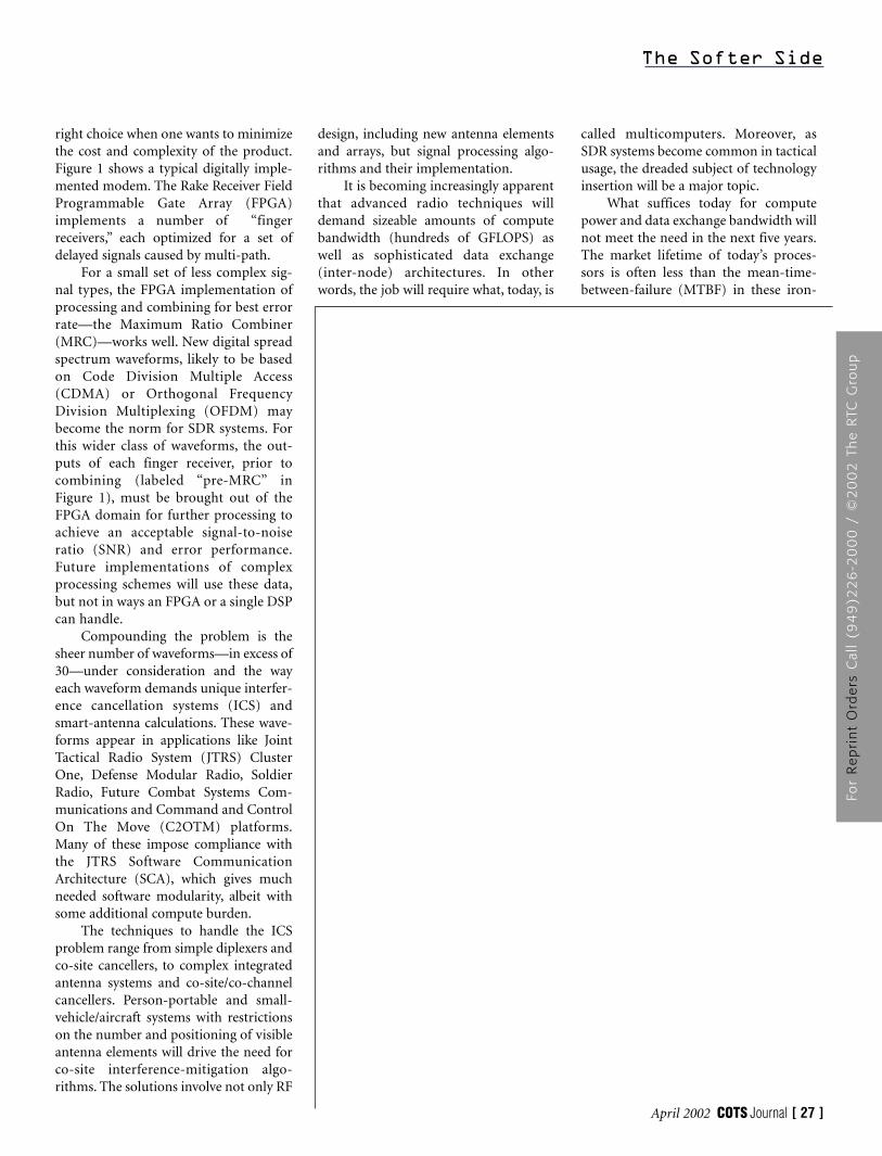
right choice when one wants to minimizethe cost and complexity of the product.Figure 1 shows a typical digitally imple-mented modem. The Rake Receiver FieldProgrammable Gate Array (FPGA)implements a number of “fingerreceivers,” each optimized for a set ofdelayed signals caused by multi-path.
For a small set of less complex sig-nal types, the FPGA implementation ofprocessing and combining for best errorrate—the Maximum Ratio Combiner(MRC)—works well. New digital spreadspectrum waveforms, likely to be basedon Code Division Multiple Access(CDMA) or Orthogonal FrequencyDivision Multiplexing (OFDM) maybecome the norm for SDR systems. Forthis wider class of waveforms, the out-puts of each finger receiver, prior tocombining (labeled “pre-MRC” inFigure 1), must be brought out of theFPGA domain for further processing toachieve an acceptable signal-to-noiseratio (SNR) and error performance.Future implementations of complexprocessing schemes will use these data,but not in ways an FPGA or a single DSPcan handle.
Compounding the problem is thesheer number of waveforms—in excess of30—under consideration and the wayeach waveform demands unique interfer-ence cancellation systems (ICS) andsmart-antenna calculations. These wave-forms appear in applications like JointTactical Radio System (JTRS) ClusterOne, Defense Modular Radio, SoldierRadio, Future Combat Systems Com-munications and Command and ControlOn The Move (C2OTM) platforms.Many of these impose compliance withthe JTRS Software CommunicationArchitecture (SCA), which gives muchneeded software modularity, albeit withsome additional compute burden.
The techniques to handle the ICSproblem range from simple diplexers andco-site cancellers, to complex integratedantenna systems and co-site/co-channelcancellers. Person-portable and small-vehicle/aircraft systems with restrictionson the number and positioning of visibleantenna elements will drive the need forco-site interference-mitigation algo-rithms. The solutions involve not only RF
design, including new antenna elementsand arrays, but signal processing algo-rithms and their implementation.
It is becoming increasingly apparentthat advanced radio techniques willdemand sizeable amounts of computebandwidth (hundreds of GFLOPS) aswell as sophisticated data exchange(inter-node) architectures. In otherwords, the job will require what, today, is
called multicomputers. Moreover, asSDR systems become common in tacticalusage, the dreaded subject of technologyinsertion will be a major topic.
What suffices today for computepower and data exchange bandwidth willnot meet the need in the next five years.The market lifetime of today’s proces-sors is often less than the mean-time-between-failure (MTBF) in these iron-
The Softer Side
April 2002 COTS Journal [ 27 ]
For
Re
pri
nt
Ord
ers
Cal
l (9
49
)22
6-2
00
0 /
©2
00
2 T
he
RTC
Gro
up
clad, battle-ready systems. System own-ers want to know that industry gavethem configurations with strong tech-nology insertion scenarios, with the abil-ity to survive and capitalize on commer-cial processor changes. All of theserequirements demand approaches withthe best flexibility available, now and inthe future.
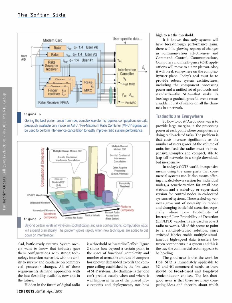
Hidden in the future of digital radio
is a threshold or “waterline” effect. Figure2 shows how beyond a certain point inthe space of functional complexity andnumber of users, the amount of computehorsepower demanded exceeds the com-pute ceiling established by the first waveof SDR systems. The challenge is that onecan’t predict exactly when and where itwill happen in terms of the phased pro-curements and deployments, nor how
high to set the threshold.It is known that early systems will
have breakthrough performance gains,there will be glowing reports of changesin communication effectiveness andCommand, Control, Communications,Computers and Intelli-gence (C4I) appli-cations will move to a new plateau. Also,it will break somewhere on the complex-ity/user plane. Today’s goal must be toprovide robust system architectures,including the component processingpower and a unified set of protocols andstandards—the SCA—that make itsbreakage a gradual, graceful event versusa sudden burst of silence on all the chan-nels in a network.
Tradeoffs are EverywhereSo how to do it? An obvious way is to
provide large margins in the processingpower at each point where computers aredoing radio-related tasks. The problem isthat costs increase significantly as thenumber of users grows. At the volume ofunits involved, the radios must be inex-pensive. Complex and compact, able toleap tall networks in a single download,but inexpensive.
In today’s COTS world, inexpensivemeans using the same parts that com-mercial systems use. It also means offer-ing a scaled-down version for individualnodes, a generic version for small basestations and a scaled-up or super-sizedversion for control nodes in co-locatedsystems-of-systems. These scaled-up ver-sions grow out of necessity in mobileand changing battlefield scenarios, espe-cially where Low Probability ofIntercept/ Low Probability of Detection(LPI/LPD) waveforms are used in covertradio networks. All of this seems to pointto a switched-fabric solution, sinceswitched fabrics enable multiple simul-taneous high-speed data transfers be-tween components in a system and this isthe way the commercial sector appears tobe heading.
The good news is that the work forDoD SDR is immediately applicable to3G and 4G commercial needs, so thereshould be broad-based and long-livedsemiconductor choices. The less-than-good news is that there are many com-peting ideas and theories about which
The Softer Side
[ 28 ] COTS Journal April 2002
Beyond certain levels of waveform sophistication and user configurations, computation loadswill expand dramatically. The problem grows rapidly when new techniques are added to cutdown on interference.
Getting the best performance from new, complex waveforms requires computations on datapreviously available only inside an ASIC. “Pre-Maximum Ratio Combiner (MRC)” signals canbe used to perform interference cancellation to vastly improve radio system performance.
Figure 1
Figure 2
For
Re
pri
nt
Ord
ers
Cal
l (9
49
)22
6-2
00
0 /
©2
00
2 T
he
RTC
Gro
up
will survive. There are parallel standards(such as RACEway 32-bit/circuitswitched and RapidIO 8-bit/16-bit/pack-et switched) as well as serial standards,many of which leverage the LVDS physi-cal layer (Gbit Ethernet/ATM/Fibre-Channel, Infiniband, Serial RapidIO).
Then there is a deep field of proces-sor technologies contending for variousshares of the commercial market: generalpurpose processors (GPPs) like thePowerPC; digital signal processors(DSPs) like StarCore and TI C6x; embed-dable VHDL processor cores like ARM,MIPS and PPC 603e; embeddable bridgesand crossbars, reconfigurable systems-on-a-chip, et cetera. To add further com-plexity, not all of these choices conformto the emerging SCA standards. It is goodto have choices, sometimes, but this maybe too much!
From the point of view of SDR, thecritical dimension appears to be scalabil-ity in terms of being able to build smallchip-count portable devices, smallboard-count mobile and fixed base-sta-tion devices and large box-count com-mand and control systems. The process-ing paradigm at each node is less an issuethan the node’s ability to be an endpointon a dynamic and fluid processing fabric.
Flexibility for the FutureIn terms of multicomputer struc-
tures for SDR, fabric technology seemsto be the answer for the next few gener-ations of powerful, deployable and scal-able systems. The ability to design SDRalgorithms, waveform techniques andeven system components that enjoylong and successful lives in the fieldhinges on ensuring that the first systemsare built around the need for a highrange of scalability.
Flexible, scalable designs aid com-pliance to software-radio-architecturespecifications such as the SCA or to thenew software radio standards being pro-posed by the Object Management Group(OMG) and other standards organiza-tions. The first step in designing for scal-ability is to provide the right “hooks” forfunctional scalability in the future, espe-cially when designing “bare-bones,” best-value software radios. Hooks include theinterconnect techniques and the ability
to stay true to the architecture at thechip-, board- and box-level. Simply put,one needs to select an approach thatscales down to a hand-held radio and upto a vanload of radios and networkinghardware.
Mercury Computer Systems, Inc.Chelmsford, MA.(978) 256-1300.[www.mc.com].
The Softer Side
April 2002 COTS Journal [ 29 ]
For
Re
pri
nt
Ord
ers
Cal
l (9
49
)22
6-2
00
0 /
©2
00
2 T
he
RTC
Gro
up
Part 2: Software Defined Radios
April 2002 COTS Journal [ 31 ]
S ince the early days of backpack AMradios, military planners havesought more efficient methods for
wireless battlefield communications. Thisrelentless trend has resulted in today’s real-ity of hundreds of different signals acrossthe electromagnetic spectrum, varyingfrom simple narrowband modulations tohighly complex secure wideband schemes.A large percentage of these signals are usedfor communications; however, applica-tions such as range and direction finding,navigation, remote imaging and controlalso share the spectrum.
Traditional methods for dealing withall these signals are breaking down.Today, individual pieces of equipmentare used for each signal type. A MILSTARsatellite radio is different from that of aUHF tactical radio, which is differentagain from an IFF (identification, friend
or foe) transponder or a GPS receiver.This fragmentation results in the require-ment for multiple pieces of equipmentconsuming large amounts of space,weight and power, greatly limiting theareas in which they can be applied.
This issue is significant in a tacticalsituation where the need may exist towork with perhaps a half-dozen signaltypes. But it becomes almost overwhelm-ing on a strategic scale, because in a con-flict situation the problem instantly mul-tiplies in scope. Friendly signals fromone’s own and allied forces must bereceived, transmitted and secured frominterference. This is a relatively pre-dictable task. However, hostile signalsmust be located, identified, intercepted,decoded, range and direction found,and blurred or jammed as required.Moreover, these signals may span therange from simple VHF communicationsto gigahertz frequency-agile radar pulses.For an army to gain information superi-ority on the modern battlefield, everyone of these signals must be processed
and responded to in real time.This becomes an impossible prob-
lem using traditional techniques. Anentire AWACS loaded with racks ofequipment would still be unable to coverall of the signals that may conceivably beused, as the number of signals of interestmay range from several hundred to overone thousand. Clearly what is needed is atotally new way of dealing with these sig-nals. It was for this reason that the JointTactical Radio System (JTRS) programwas introduced. This program defines astandardized way of utilizing SoftwareDefined Radio (SDR) architectures sothese problems can efficiently beaddressed. In so doing it has also becomea driving force for the adoption of SDRin military wireless applications.
SDR PrimerThe basic premise behind SDR is to
use digital signal processing techniques inplace of today’s predominantly analog sig-nal processing. By replacing the hardwiredanalog circuits with reprogrammable soft-
Softer SideOn The
Frank Van Hooft, System Engineering ManagerandMohammad Darwish, Senior Technical Lead;Spectrum Signal Processing
A Reconfigurable Software DigitalRadio Architecture for ElectronicSignal Interception, Identification,Communication and Jamming
Software programmable radios, such as those planned for use in JTRS, are bestimplemented by a balanced architecture using CPUs, FPGAs and a high-speedinterconnect such as RapidIO.
For
Re
pri
nt
Ord
ers
Cal
l (9
49
)22
6-2
00
0 /
©2
00
2 T
he
RTC
Gro
up
ware, a “digital radio” is able to change itspersonality on-the-fly, switching from onemodulation method to another in thetime a processor takes to branch to a newinstruction. A single piece of equipmentbecomes capable of handling a multitudeof different signal types (waveforms), pro-viding a drastic reduction in the space,weight and power requirements for thesystem. Additionally, by building uponMoore’s Law in the semiconductor space,rapid improvements in performance andsize can be reliably predicted for futuregenerations of equipment.
An SDR radio’s rapid reconfigurabil-ity offers other advantages. Ultra-fast hopwaveforms can be widely utilized.Cryptographic keys can be updated inreal time, from today’s 4-hour updaterate to several-minute or even faster ratesin the future. Radios can even be updatedremotely, while deployed, as circum-stances demand without having to beremoved from service and shipped to amaintenance facility.
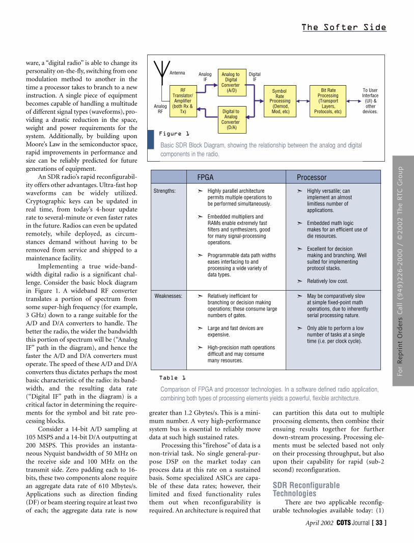
Implementing a true wide-band-width digital radio is a significant chal-lenge. Consider the basic block diagramin Figure 1. A wideband RF convertertranslates a portion of spectrum fromsome super-high frequency (for example,3 GHz) down to a range suitable for theA/D and D/A converters to handle. Thebetter the radio, the wider the bandwidththis portion of spectrum will be (“AnalogIF” path in the diagram), and hence thefaster the A/D and D/A converters mustoperate. The speed of these A/D and D/Aconverters thus dictates perhaps the mostbasic characteristic of the radio: its band-width, and the resulting data rate(“Digital IF” path in the diagram) is acritical factor in determining the require-ments for the symbol and bit rate pro-cessing blocks.
Consider a 14-bit A/D sampling at105 MSPS and a 14-bit D/A outputting at200 MSPS. This provides an instanta-neous Nyquist bandwidth of 50 MHz onthe receive side and 100 MHz on thetransmit side. Zero padding each to 16-bits, these two components alone requirean aggregate data rate of 610 Mbytes/s.Applications such as direction finding(DF) or beam steering require at least twoof each; the aggregate data rate is now
greater than 1.2 Gbytes/s. This is a mini-mum number. A very high-performancesystem bus is essential to reliably movedata at such high sustained rates.
Processing this “firehose” of data is anon-trivial task. No single general-pur-pose DSP on the market today canprocess data at this rate on a sustainedbasis. Some specialized ASICs are capa-ble of these data rates; however, theirlimited and fixed functionality rulesthem out when reconfigurability isrequired. An architecture is required that
can partition this data out to multipleprocessing elements, then combine theirensuing results together for furtherdown-stream processing. Processing ele-ments must be selected based not onlyon their processing throughput, but alsoupon their capability for rapid (sub-2second) reconfiguration.
SDR ReconfigurableTechnologies
There are two applicable reconfig-urable technologies available today: (1)
The Softer Side
April 2002 COTS Journal [ 33 ]
Basic SDR Block Diagram, showing the relationship between the analog and digitalcomponents in the radio.
Figure 1
Bit RateProcessing(Transport
Layers,Protocols, etc)
Analog toDigital
Converter(A/D)
Digital toAnalog
Converter(D/A)
RFTranslator/Amplifier
(both Rx &Tx)
Antenna
To UserInterface
(UI) &other
devices.Analog
RF
AnalogIF
DigitalIF
SymbolRate
Processing(Demod,Mod, etc)
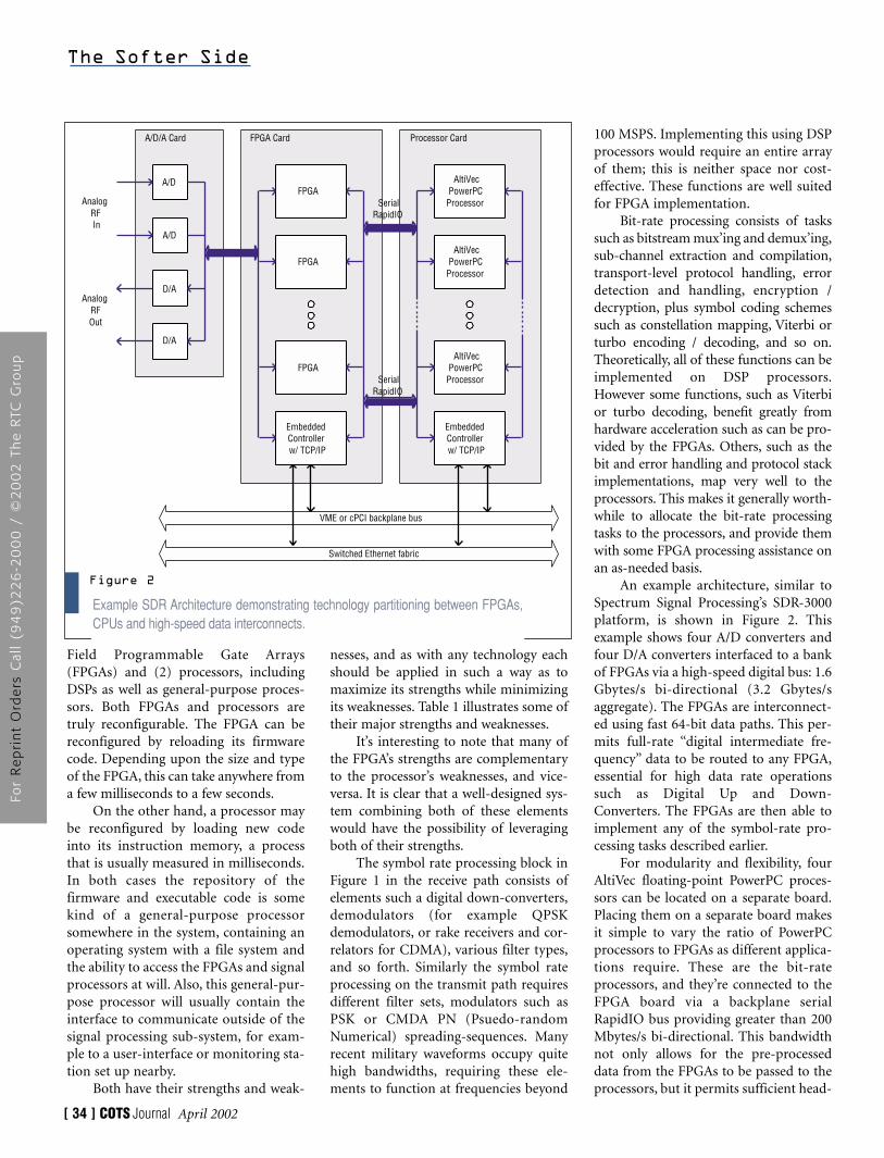
Comparison of FPGA and processor technologies. In a software defined radio application,combining both types of processing elements yields a powerful, flexible architecture.
Table 1
Highly parallel architecturepermits multiple operations tobe performed simultaneously.
Embedded multipliers andRAMs enable extremely fastfilters and synthesizers, goodfor many signal-processingoperations.
Programmable data path widthseases interfacing to andprocessing a wide variety ofdata types.
Strengths: ➣
➣
➣
Highly versatile; canimplement an almostlimitless number ofapplications.
Embedded math logicmakes for an efficient use ofdie resources.
Excellent for decisionmaking and branching. Wellsuited for implementing protocol stacks.
Relatively low cost.
➣
➣
➣
➣
Relatively inefficient forbranching or decision makingoperations; these consume largenumbers of gates.
Large and fast devices areexpensive.
High-precision math operationsdifficult and may consume many resources.
Weaknesses: ➣
➣
➣
May be comparatively slowat simple fixed-point mathoperations, due to inherentlyserial processing nature.
Only able to perform a lownumber of tasks at a singletime (i.e. per clock cycle).
➣
➣
FPGA Processor
For
Re
pri
nt
Ord
ers
Cal
l (9
49
)22
6-2
00
0 /
©2
00
2 T
he
RTC
Gro
up
Field Programmable Gate Arrays(FPGAs) and (2) processors, includingDSPs as well as general-purpose proces-sors. Both FPGAs and processors aretruly reconfigurable. The FPGA can bereconfigured by reloading its firmwarecode. Depending upon the size and typeof the FPGA, this can take anywhere froma few milliseconds to a few seconds.
On the other hand, a processor maybe reconfigured by loading new codeinto its instruction memory, a processthat is usually measured in milliseconds.In both cases the repository of thefirmware and executable code is somekind of a general-purpose processorsomewhere in the system, containing anoperating system with a file system andthe ability to access the FPGAs and signalprocessors at will. Also, this general-pur-pose processor will usually contain theinterface to communicate outside of thesignal processing sub-system, for exam-ple to a user-interface or monitoring sta-tion set up nearby.
Both have their strengths and weak-
nesses, and as with any technology eachshould be applied in such a way as tomaximize its strengths while minimizingits weaknesses. Table 1 illustrates some oftheir major strengths and weaknesses.
It’s interesting to note that many ofthe FPGA’s strengths are complementaryto the processor’s weaknesses, and vice-versa. It is clear that a well-designed sys-tem combining both of these elementswould have the possibility of leveragingboth of their strengths.
The symbol rate processing block inFigure 1 in the receive path consists ofelements such a digital down-converters,demodulators (for example QPSKdemodulators, or rake receivers and cor-relators for CDMA), various filter types,and so forth. Similarly the symbol rateprocessing on the transmit path requiresdifferent filter sets, modulators such asPSK or CMDA PN (Psuedo-randomNumerical) spreading-sequences. Manyrecent military waveforms occupy quitehigh bandwidths, requiring these ele-ments to function at frequencies beyond
100 MSPS. Implementing this using DSPprocessors would require an entire arrayof them; this is neither space nor cost-effective. These functions are well suitedfor FPGA implementation.
Bit-rate processing consists of taskssuch as bitstream mux’ing and demux’ing,sub-channel extraction and compilation,transport-level protocol handling, errordetection and handling, encryption /decryption, plus symbol coding schemessuch as constellation mapping, Viterbi orturbo encoding / decoding, and so on.Theoretically, all of these functions can beimplemented on DSP processors.However some functions, such as Viterbior turbo decoding, benefit greatly fromhardware acceleration such as can be pro-vided by the FPGAs. Others, such as thebit and error handling and protocol stackimplementations, map very well to theprocessors. This makes it generally worth-while to allocate the bit-rate processingtasks to the processors, and provide themwith some FPGA processing assistance onan as-needed basis.
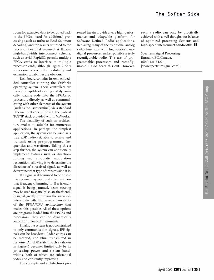
An example architecture, similar toSpectrum Signal Processing’s SDR-3000platform, is shown in Figure 2. Thisexample shows four A/D converters andfour D/A converters interfaced to a bankof FPGAs via a high-speed digital bus: 1.6Gbytes/s bi-directional (3.2 Gbytes/saggregate). The FPGAs are interconnect-ed using fast 64-bit data paths. This per-mits full-rate “digital intermediate fre-quency” data to be routed to any FPGA,essential for high data rate operationssuch as Digital Up and Down-Converters. The FPGAs are then able toimplement any of the symbol-rate pro-cessing tasks described earlier.
For modularity and flexibility, fourAltiVec floating-point PowerPC proces-sors can be located on a separate board.Placing them on a separate board makesit simple to vary the ratio of PowerPCprocessors to FPGAs as different applica-tions require. These are the bit-rateprocessors, and they’re connected to theFPGA board via a backplane serialRapidIO bus providing greater than 200Mbytes/s bi-directional. This bandwidthnot only allows for the pre-processeddata from the FPGAs to be passed to theprocessors, but it permits sufficient head-
The Softer Side
[ 34 ] COTS Journal April 2002
Example SDR Architecture demonstrating technology partitioning between FPGAs,CPUs and high-speed data interconnects.
Figure 2
AltiVecPowerPC
Processor
AnalogRFIn
A/D/A Card
AltiVecPowerPC
Processor
AltiVecPowerPC
Processor
FPGA
FPGA
FPGA
EmbeddedControllerw/ TCP/IP
EmbeddedControllerw/ TCP/IP
A/D
A/D
D/A
D/A
D/A
A/D
FPGA Card Processor Card
AnalogRFOut
VME or cPCI backplane bus
Switched Ethernet fabric
SerialRapidIO
SerialRapidIO
For
Re
pri
nt
Ord
ers
Cal
l (9
49
)22
6-2
00
0 /
©2
00
2 T
he
RTC
Gro
up
room for extracted data to be routed backto the FPGA board for additional pro-cessing (such as turbo or Reed Solomondecoding) and the results returned to theprocessor board, if required. A flexiblehigh-bandwidth interconnect scheme,such as serial RapidIO, permits multipleFPGA cards to interface to multipleprocessor cards, although Figure 2 onlyshows one of each, the modularity andexpansion capabilities are obvious.
Each board contains its own embed-ded controller running the VxWorksoperating system. These controllers aretherefore capable of storing and dynami-cally loading code into the FPGAs orprocessors directly, as well as communi-cating with other elements of the system(such as the user terminal) via a standardEthernet network utilizing the robustTCP/IP stack provided within VxWorks.
The flexibility of such an architec-ture makes it suitable for numerousapplications. In perhaps the simplestapplication, the system can be used as atrue SDR radio set, able to receive andtransmit using pre-programmed fre-quencies and waveforms. Taking this astep further, the system can additionallyimplement features such as direction-finding and automatic modulationrecognition, allowing it to determine thedirection of a received signal, as well asdetermine what type of transmission it is.
If a signal is determined to be hostilethe system may optionally transmit onthat frequency, jamming it. If a friendlysignal is being jammed, beam steeringmay be used to spatially isolate the friend-ly signal, greatly improving the signal-of-interest strength. It’s the reconfigurabilityof the FPGA/CPU architecture thatmakes this possible. All of these optionsare programs loaded into the FPGAs andprocessors; they can be dynamicallyloaded or unloaded in moments.
Finally, the system is not constrainedto only communication signals. IFF sig-nals can be broadcast. Radar chirps canbe received, and blurs transmitted inresponse. An SDR system such as shownin Figure 2 becomes limited only by itsprocessing power and system band-widths, both of which are substantialtoday and constantly improving.
The concepts and architectures pre-
sented herein provide a very high-perfor-mance and adaptable platform forSoftware Defined Radio applications.Replacing many of the traditional analogradio functions with high-performancedigital processors makes possible a trulyreconfigurable radio. The use of pro-grammable processors and reconfig-urable FPGAs bears this out. However,
such a radio can only be practicallyachieved with a well thought-out balanceof optimized processing elements andhigh-speed interconnect bandwidths.
Spectrum Signal Processing Burnaby, BC, Canada.(604) 421-5422.[www.spectrumsignal.com].
The Softer Side
April 2002 COTS Journal [ 35 ]
For
Re
pri
nt
Ord
ers
Cal
l (9
49
)22
6-2
00
0 /
©2
00
2 T
he
RTC
Gro
up