Embed Size (px)
Citation preview
HAL Id: tel-00752100https://tel.archives-ouvertes.fr/tel-00752100
Submitted on 14 Nov 2012
HAL is a multi-disciplinary open accessarchive for the deposit and dissemination of sci-entific research documents, whether they are pub-lished or not. The documents may come fromteaching and research institutions in France orabroad, or from public or private research centers.
L’archive ouverte pluridisciplinaire HAL, estdestinée au dépôt et à la diffusion de documentsscientifiques de niveau recherche, publiés ou non,émanant des établissements d’enseignement et derecherche français ou étrangers, des laboratoirespublics ou privés.
Ontology centric design process : Sharing aconceptualization
Ofaina Taofifenua
To cite this version:Ofaina Taofifenua. Ontology centric design process : Sharing a conceptualization. Other [cs.OH].Conservatoire national des arts et metiers - CNAM, 2012. English. <NNT : 2012CNAM0818>. <tel-00752100>
CONSERVATOIRE NATIONAL DESARTS ET MÉTIERS
École Doctorale EDITE
Laboratoire CEDRIC
THÈSE DE DOCTORAT
présentée par : Ofaina TAOFIFENUA
soutenue le : 10 Juillet 2012
pour obtenir le grade de : Docteur du Conservatoire National des Arts et Métiers
Discipline / Spécialité : Informatique
ONTOLOGY CENTRIC DESIGN PROCESS
Sharing a Conceptualization
THÈSE dirigée par
Mme LÉVY Nicole CNAM, CEDRIC
RAPPORTEURS
M. AIT-AMEUR Yamine ENSEEIHT, IRITM. KAANICHE Mohamed LAAS-CNRS
EXAMINATEURS
Mme DUBOIS Catherine ENSIIE, CEDRICM. BELMONTE Fabien ALSTOMM. BOULANGER Jean-Louis CERTIFERM. GAUDRÉ Thierry RENAULT

"New knowledge is the most valuable commodity on earth. The more truth we have towork with, the richer we become."
Kurt Vonnegut, Breakfast of Champions
Acknowledgements
The work at the origin of this thesis have been realized jointly at Renault's DELTA
("Direction de l'Électronique et des Technologies Avancées") in the system and software
department within the team SAEE ("Sytème et Architecture Électrique Électronique) and
at CNAM's SITI (École Sciences industrielles & technologies de l'information) in team CPR
("systèmes sûrs: Conception et Programmation Raisonnées") of the CEDRIC ("Centre
d'Étude et De Recherche en Informatique et Communications") laboratory. So I take this
opportunity to thank Pr Bastard and Pr Himbert respective directors of DELTA and SITI.
I give my thanks to my department head and successive team managers at Renault, Bruno
Font, Olivier Guetta, Hugo Chalé, Philippe Quéré and Christophe Dang. Similarly I give
my thanks to CEDRIC's director Pr Crucianu. I also want to thank CPR's team manager
Pr Dubois. To all these people, a big thank you for welcoming me in your organization.
I would also like to express my deepest thanks to Nicole Lévy who kindly agreed
to supervise this PhD thesis, Thierry Gaudré my Renault's supervisor and Jean-Louis
Boulanger who kindly agreed to share his expertise in this work. Without their availability,
patience, support, guidance, words of encouragement, provided throughout these three
years, this thesis could probably not have been possible. I will never thank them enough
for the trust they put in my person by taking me as a PhD candidate. Please �nd here the
testimony of my gratitude and kind regards.
I would like to thank Mohamed Kaâniche and Yamine Ait-Ameur who accepted the
burden of rapporteur. They also agreed to be part of my jury. I give my thanks to
Catherine Dubois and Fabien Belmonte in addition to my rapporteurs and supervisors for
making me the honor to examine my work. Their presence in the jury is my pleasure.
3
The sta� of the department, by their kindness and friendliness which they have demon-
strated during my presence, have made my stay very pleasant among them. I want to
thank the department's team of engineers: Atef, Boubker, Cosmin, Emmanuel, François,
Frédéric, Hoang, Hugo, Joris, Ludovic, Patrick, Pascal (the two of them) Paul-Éric, Paulo,
Philippe, Régis, Rémy, Saidou, Sann, Sophie, Sylvain, Thierry, Xavier and Youssef. They
were able to make warm and fruitful these past few years among them by their human
qualities and skills. I have fond memories of the many discussions, professional and non-
professional, which have enriched me personally. In particular, I would like to address
my acknowledgment to Hugo and Thierry who took great interest in this work and gave
much support both in time and expertise. I also thank the department's administrative
sta�, Catherine, Christine and the two Dominique, for their e�ectiveness and all services
provided.
I would like to address my acknowledgments to the sta� of the LISV ("Laboratoire
d'Ingénierie des Systémes de Versailles") who welcomed me in their laboratory. I want
to express my gratitude to Pr Amar who provided unconditional support. I don't forget
my comrades who shared and shares similar experience that helped to put in perspective
my personal one. A big thank you to Hassan, Rima, Sébastien, Mona, Maya, Mata and
Sylvain. I also give my thanks to LISV administrative sta�, Catherine and Dominique for
they availability and all services provided.
I think it is appropriate to give my acknowledgments to all my teachers and professors
encountered during my academic. Thank you for giving me the desire to continue in studies.
In particular, I want to address my thanks to Alain Gri�ault, David Powell and Jérémie
Giochet who introduced me to dependability which is the domain I deeply connected with.
A big thank you to all my friends who supported me for so many years: Albane, Céline,
Enzo, Fa Yuan, Frédérique, Jonathan, Julianna, Landry, Moana, Raimana (the two of
them), Rémy, Sara and Vincent. Thank you for putting up with my person during di�cult
times and trying to make me relax. I don't forget my friends outside of metropolitan France:
Brandon, Carole, Diego, Heimanarii, Heimata, Jake, Julianna, Maui, Moana, Namoiata,
Nicolas, Raihei, Teiki, Titaina, Vétéa, Yannick and Yvonnick. Thank you for making me
live in your mind, you live in mine too.
4

My deepest gratitude goes to my wonderful family which is my personal blessing. Thank
you all for your unconditional support and love. A special mention goes to my loving mother
and her husband. Thank you for believing in me in di�cult times and giving me all the
means to continue my studies. I address my thanks to my brother and sister for giving me
additional hardships. I do not love you less. Finally, my thoughts goes to my late father
to whom this thesis is dedicated.
5

6
Abstract
For the last several years, car manufacturers have had to face an always-increasing list of
stakes and challenges. In the strongly competitive worldwide market of today, a car man-
ufacturer has to o�er to its customers relevant, innovative, reliable, environment friendly
and safe services of the highest quality. All this must be done at very competitive costs
while complying with more and more stringent regulations and tighter deadlines. This
work addresses these challenges and aims at improving the design process for automotive
safety critical mechatronics systems. In addition, the introduction of systems engineering
at Renault and the emergence of international standard ISO 26262 (published in November
2011) that addresses functional safety in the automotive are central considerations.
At Renault, systems engineering introduction leans towards model-based systems engi-
neering where di�erent models with respective viewpoints about one system are developed
during the design phase. The �rst implementations of the design process were mainly
document-centric and depended largely on testing and simulation. Although these �rst
attempts yielded quite satisfactory results, the creation of the di�erent objects of the pro-
cess was somewhat troublesome and relatively time-consuming. The reason for this is that
the objects were modeled by means of transformations of ad-hoc data and information
contained in the di�erent documents that were transmitted from one process step to the
other. The main di�culty in implementing the process consisted in the lack of semantic
consistency among the di�erent modeled objects.
Functional safety studies are carried out following a second process in parallel to the
precedent design process. These two processes are interfaced to develop safe systems.
These two processes manipulate some concepts that are similar, however with a di�erent
conceptualization. These di�erent conceptualizations are translated in loss of knowledge
7
at the processes interfaces which imped communication between the two domains as they
can be incompatible and can potentially result in undetectable inconsistencies.
This need for a better formalization is further stressed by the fact that car manufac-
turers rely heavily on third parties that also have their own conceptualizations. Better
formalization of processes and of the process objects would certainly contribute to avoid
confusion and misinterpretations in the development of systems.
All this led us to the conclusion that the use of formal and informal models can commit
to a common semantic model, i.e., a system and safety ontology, that enables to ensure
the consistency of the whole design process and compliance with ISO 26262. The improved
design process is called ontology centric design process. The concepts in this work have been
applied on a regenerative hybrid braking system integrated into a full electrical vehicle. It
demonstrated that the realized ontology enables to record the information produced during
design and that using ontologies e�ectively enables to detect semantic inconsistencies which
improves design information quality, promotes reuse and ensures ISO 26262 compliance.
8

Résumé
Les constructeurs automobiles doivent faire face à une liste toujours croissante d'enjeux
et dé�s. Dans le marché mondial fortement concurrentiel actuel, un constructeur doit o�rir
à ses clients des services de la plus haute qualité. Ces derniers doivent être pertinents, no-
vateurs, �ables, respectueux de l'environnement et sûrs. Tout ceci doit se faire à des coûts
très compétitifs tout en respectant des réglementations de plus en plus strictes et des délais
de plus en plus courts. Les travaux présentés dans ce mémoire de thèse répondent à ces at-
tentes et visent à améliorer le processus de conception des systèmes mécatroniques critiques
automobile. En particulier, nous avons cherché à évaluer la contribution des techniques
formelles, en continuité ou en rupture, sur le processus de développement des systèmes
mécatroniques, qui doit être conforme à l'ISO 26262, d'un constructeur automobile tel que
Renault. Nous cherchons notamment à répondre aux questions de recherche suivantes :
Q1 Comment les connaissances du domaine (automobile) peuvent être formalisées ?
Q2 Comment les connaissances d'experts sur le processus de développement peuvent être
formalisées ?
Q3 Comment le respect de la norme ISO 26262 peut être véri�é ?
Chapitre 1. L'objectif du premier chapitre est de présenter les domaines contextuels
ainsi que les bases théoriques sur lesquelles se fonde notre travail. Dans un premier temps,
nous présentons le processus de développement produit, par la discipline qui s'est dévelop-
pée autour de l'élément central appelé système : l'ingénierie des systèmes. Cette discipline
s'attache à dé�nir des processus (activités), supportés par des méthodes (techniques), elles
mêmes supportées par des outils. La représentation usuelle du processus de développe-
10
ment système est le cycle en V. Cette représentation dé�nit trois phases générales. La
branche descendante du V correspond à la conception, la base adresse la réalisation et la
branche ascendante représente l'intégration du système. Dans nos travaux nous ne consid-
érons que la conception. Cette phase peut être résumée à l'ingénierie des exigences (où des
exigences sont dé�nies et décrivent le système en devenir) et à la conception des architec-
tures (fonctionnelle et physique) systèmes. Une autre spécialité s'est également développée
pour prendre en compte les systèmes dits critiques (à enjeux de sécurité, économiques et
environnementaux) : la sûreté de fonctionnement. Quand les conséquences d'un mauvais
fonctionnement sont catastrophiques pour l'utilisateur, on parle de sécurité-innocuité et
de sécurité fonctionnelle. Les activités de la sécurité fonctionnelle se représentent dans un
deuxième cycle en V exécuté en parallèle du processus de développement usuel a�n de dé-
montrer l'absence de risques inacceptables. Pour �nir, les principales méthodes utilisées en
ingénierie des systèmes sont présentées avec un bref focus sur MOF, le standard de l'OMG,
qui permet de représenter et manipuler des métas-modèles. En se basant sur MOF, il est
possible d'uni�er toutes les étapes du développement mais il reste cependant un problème
d'intégration (sémantique des outils).
Le chapitre poursuit sur les ontologies et met l'accent sur les ontologies formelles qui
nous intéressent. Ces dernières permettent de formaliser un domaine en dé�nissant les
éléments suivants ainsi que des propriétés sur ces éléments : individus, classes, propriétés
et attributs. Ces dé�nitions sont l'objet d'axiomes qui dé�nissent des assertions sur un
domaine particulier qui peuvent également contenir la théorie dérivée des formules axioma-
tiques génératives. De plus, les ontologies contiennent également des axiomes qui rendent
les hypothèses d'un domaine explicites pour les humains et les systèmes informatiques.
Cette structure mathématique permet le raisonnement mathématique spéci�que en fonc-
tion de la logique et de la fonction d'interprétation utilisées. La fonction d'interprétation
associe les valeurs habituelles vrai ou faux aux assertions du domaine quand l'hypothèse
du monde fermé est prise, i.e., ce qui n'est pas connu pour être vrai est faux. Une autre
hypothèse peut cependant être prise rajoutant un individu au domaine d'interprétation
: l'hypothèse du monde ouvert, i.e., ce qui n'est pas connu pour être vrai est inconnu.
Ces bases mathématiques font que les ontologies formelles ont une propriété de cohérence
11
mathématique, i.e., présence ou non de contradiction. Au �nal, les ontologies formelles
sont l'artefact idéal pour conceptualiser une compréhension commune de disciplines mul-
tiples a�n de dé�nir le terrain d'entente sur lequel di�érents acteurs peuvent s'entendre et
répondre au problème d'intégration ou de cohérence sémantique identi�é plus loin. Nous
�nissons sur les ontologies en présentant les technologies du web sémantique que nous avons
choisi d'utiliser dans nos travaux. OWL, le langage ontologique du web, permet de dé�nir
des classes (concepts), des propriétés (propriétés et attributs) et des instances (individus).
SWRL, le langage de règles du web sémantique, ajoute la capacité de dé�nir des règles pour
des ontologies en OWL. Et SQWRL, le langage de requêtes du web sémantique, permet
d'extraire des informations des ontologies en OWL.
Le chapitre 1 conclut en présentant les travaux connexes, notamment les travaux sur
l'intégration sémantique (d'outils) dont nous reprenons les idées pour les amener plus loin
vers la cohérence sémantique du processus de conception système.
Chapitre 2. Ce chapitre présente les contributions apportées. Nous commençons par
les ontologies de domaine sur l'ingénierie des systèmes puis sur la sécurité fonctionnelle.
Bien que nous ayons choisi d'utiliser les technologies du web sémantique, les ontologies sont
présentées en utilisant la logique du premier ordre a�n de faciliter la lecture (en particulier,
le lecteur peut prendre l'hypothèse plus courante du monde fermé).
En ingénierie des systèmes nous avons pris en compte les activités les plus générales
d'analyse du besoin, d'ingénierie des exigences et de conception d'architectures. Le vocab-
ulaire utilisé lors de ces activités a été formalisé (dé�ni, structuré et contraint) en OWL en
s'inspirant des dé�nitions de l'INCOSE (l'organisation de référence dédiée à l'avancement
de l'ingénierie des systèmes, de l'AFIS (la branche française de l'INCOSE) et du vocabu-
laire utilisé à Renault. La formalisation est relativement simple pour l'analyse des besoins.
Le point à retenir est que les besoins doivent êtres pris en compte par des exigences ce
qui est formalisé avec une propriété reliant les besoins aux exigences. Pour l'ingénierie des
exigences, nous avons fait les choix importants qui suivent. Les exigences considérées corre-
spondent à la conception. Elles sont structurées en graphe acyclique orienté (une hiérarchie
permettant à un élément d'avoir plusieurs parents). Les exigences sur le processus ne sont
12
par exemple pas prises en compte. Les exigences sont naturellement typées fonctionnelle et
non fonctionnelle. Les exigences sont précisément dé�nies avec les fonctionnelles donnant
lieux à des fonctions, les non fonctionnelles au niveau système sont allouées au système et les
non fonctionnelles au niveau d'abstraction inférieur sont allouées aux fonctions ou aux com-
posants. Pour la conception des architectures nous décrivons l'organisation des fonctions
et des composants. Les fonctions sont également structurées en graphe acyclique orienté
et les composants sont organisés en hiérarchie sans qu'un composant puisse avoir plusieurs
parents. L'architecture fonctionnelle décrit l'organisation des fonctions à travers les �ux
consommés et produits. Puis les fonctions sont allouées aux composants qui sont également
organisés à travers les �ux consommés et produits par les fonctions qu'ils réalisent décrivant
l'architecture physique du système. La prise en compte des exigences fonctionnelles est
donc précisément dé�nie avec leur matérialisation en fonction dans l'architecture fonction-
nelle puis la prise en compte de ces fonctions par des composants (nous avons également
donné une sémantique précise à la déclinaison des exigences fonctionnelles en fonctions et
à l'allocation des fonctions aux composants). Concernant les exigences non fonctionnelles,
nous avons donné des éléments de réponse pour leur formalisation (en vue de leurs prises
en compte). Les types d'exigences non fonctionnelles sont nombreux et pour chaque type il
faut dé�nir les éléments permettant de les concrétiser dans l'architecture fonctionnelle et /
ou physique. Par exemple, une exigence non fonctionnelle de poids allouée au système est
décomposée en exigences non fonctionnelles de poids allouées aux di�érents composants
du système. Elles peuvent être concrétisées par un attribut entier des composants et du
système avec une sémantique à choisir ce qui par exemple permettrait, une fois cet attribut
renseigné pour les composants, de calculer le poids du système automatiquement et ainsi
de véri�er que toutes les exigences de poids soient bien satisfaites.
En sécurité fonctionnelle, nous avons considéré le processus actuel de Renault et les
parties de la norme ISO 26262 au niveau système. De manière générale, la sécurité fonction-
nelle est prise en compte à travers un processus de gestion du risque contenant les activités
d'analyse du risque et d'évaluation du risque qui sont considérées dans ces travaux. Nous
avons donc formalisé tout le vocabulaire utilisé en s'inspirant des standards ISO/IEC guide
51, IEC 61508 et ISO 26262 ainsi que du vocabulaire Renault. Nous avons choisi de démar-
13
rer l'analyse du risque en partant des exigences fonctionnelles. Les notions d'exigences, de
fonctions et de composants présentes en ingénierie des systèmes sont également présentes
en sécurité fonctionnelle et reformalisées (quoique partiellement, l'idée étant de réutiliser
les dé�nitions faites dans l'ontologie d'ingénierie des systèmes). En analyse du risque, les
exigences fonctionnelles sont analysées de manière plus systématique à travers l'utilisation
d'un modèle de défaillances à appliquer pour chaque exigence a�n de déterminer des événe-
ments redoutés. A Renault, ces derniers sont soit des événements redoutés système ou des
événements redoutés clients. Les événements redoutés clients sont particulièrement intéres-
sants car la sécurité-innocuité est une propriété observable au niveau client ou véhicule,
or la notion de système correspond culturellement à un sous-système du véhicule à Re-
nault. Ils permettent donc de traiter la sécurité fonctionnelle au niveau d'abstraction
nécessaire. L'analyse du risque se poursuit en analysant ces événements redoutés a�n de
quanti�er qualitativement leur probabilité d'occurrence (E), leur contrôlabilité (C) et la
sévérité de leur conséquence (S). L'évaluation du risque se fait automatiquement en suiv-
ant la norme ISO 26262 qui fait correspondre un ASIL (un niveau d'intégrité) pour chaque
triplet (E,C,S). Ces activités doivent ensuite donner lieu à un concept de sécurité (ensem-
ble d'exigences de sécurité). Pour ce faire, l'ASIL le plus contraignant évalué pour un
événement redouté est assigné à cet événement et un objectif de sécurité (type d'exigence)
est systématiquement dé�ni comme la négation de chaque événement redouté client avec
son ASIL. L'ASIL est également dé�ni comme un attribut du système, des exigences, des
fonctions et des composants. Pour �nir, la décomposition des ASIL dé�nie dans la norme
ISO 26262 est également formalisée dans l'ontologie ce qui permet de réduire l'ASIL des
exigences. Le reste de la norme est soumise à interprétation en fonction des spéci�cités de
l'entreprise ce qui est fait dans la formalisation globale du domaine d'étude (l'ingénierie
des systèmes et la sécurité fonctionnelle).
La formalisation globale du domaine se fait en intégrant les deux ontologies ingénierie
des systèmes et sécurité fonctionnelle. En particulier nous avons vu que des concepts sim-
ilaires pouvaient être conceptualisés di�éremment dans chaque ontologie. L'intégration
doit donc permettre de s'assurer que ces deux conceptualisations ne sont pas incompati-
bles. Pour se faire, les deux ontologies sont importées dans une seule ontologie système et
14
sécurité et nous dé�nissons les concepts des deux ontologies par rapport aux autres (par
exemple, les classes équivalentes sont dé�nis comme telles, ou certaines classes sont des
sous classes de classes appartenant à l'autre ontologie, etc.). En particulier, nous avons
clari�é les notions d'objectif de sécurité comme des exigences de parties prenantes, les
exigences fonctionnelles de sécurité comme des exigences fonctionnelles système et les exi-
gences techniques de sécurité comme des exigences non fonctionnelles sur les éléments du
système. La véri�cation automatique de la cohérence de l'ontologie globale nous permet
de véri�er que les deux précédentes ontologies ne contenaient pas de concepts incompati-
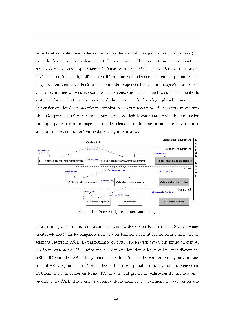
bles. Ces précisions formelles nous ont permis de dé�nir comment l'ASIL de l'évaluation
du risque pouvait être propagé sur tous les éléments de la conception en se basant sur la
traçabilité descendante présentée dans la �gure suivante.
Figure 1: Traceability for functional safety
Cette propagation se fait semi-automatiquement, des objectifs de sécurité (et des événe-
ments redoutés) vers les exigences puis vers les fonctions et �nit sur les composants en ren-
seignant l'attribut ASIL. La particularité de cette propagation est qu'elle prend en compte
la décomposition des ASIL faite sur les exigences fonctionnelles ce qui permet d'avoir des
ASIL di�érents de l'ASIL du système sur les fonctions et des composants ayant des fonc-
tions d'ASIL également di�érents. De ce fait il est possible très tôt dans la conception
d'obtenir des contraintes en terme d'ASIL qui vont guider la réalisation des architectures
précédant les ASIL plus concrets obtenus ultérieurement et également de détecter les dif-
15
férences entre ces ASIL et ceux obtenus par propagation come dé�ni dans l'ontologie. Les
synergies possibles entre plusieurs domaines peuvent donc être concrétisées par l'intégration
de domaines comme le révèle cette application de propagation d'ASIL et justi�e en partie
l'e�ort à fournir pour plus de formalisation.
Les implémentations précédentes du processus de conception système ont révélé des
di�cultés concernant la production des di�érents objets du processus basée sur des trans-
formations implicites des informations contenues dans les documents transmis à chaque
étape qui se ramène à un manque de cohérence sémantique entre ces objets. Notre réponse
à l'amélioration du processus de conception tente donc de résoudre ce problème et se con-
crétise à travers les ontologies précédentes. Nous proposons une nouvelle approche de
conception basée sur une ontologie. Cette solution place l'ontologie système et sécurité
au centre du processus de conception. L'ontologie est considérée comme LE modèle de
référence global du système auquel tous les documents et modèles de conception doivent
être conformes a�n d'assurer la cohérence de l'ensemble du processus de conception. Pour se
faire, nous nous replaçons dans le cadre de MOF a�n de dé�nir des correspondances (map-
pings) entre l'ontologie et chaque méta-modèle des documents (méta-modèle implicite) et
modèles du processus de conception. Ces correspondances permettent d'enrichir l'ontologie
au niveau instance, de réutiliser les connaissances (instances) contenues dans l'ontologie
dans les modèles (et documents), de véri�er la cohérence (syntaxique ET sémantique) d'un
modèle (ou document) en véri�ant que l'ontologie est cohérente une fois que les informa-
tions du modèle ont été enregistrées dans l'ontologie, de véri�er que deux modèles (ou
documents) sont cohérents en véri�ant que l'ontologie est cohérente après que les informa-
tions des modèles ont été enregistrées dans l'ontologie et par extension de véri�er que tous
les modèles sont cohérents et donc que l'ensemble du processus est cohérent. Un point
important concerne la nature hétérogène des modèles du processus de conception due à la
collaboration de divers acteurs ayant des conceptualisations di�érentes, notamment quand
des acteurs externes à Renault sont impliqués. Des transformations (ou interprétations)
sont faites implicitement ce qui peut mener à des incohérences. Nous identi�ons ces trans-
formations comme des transformations dans MOF a�n de montrer que les correspondances
dé�nies entre deux méta-modèles permettent de véri�er automatiquement la cohérence de
16

la transformation à travers la cohérence de l'ontologie.
Le chapitre poursuit sur la présentation du processus de conception basé sur une ontolo-
gie. Nous prévoyons que notre approche améliore le processus actuel de plusieurs façons.
Premièrement, l'écriture des exigences et l'établissement de leur traçabilité se fait avec
l'interprétation sémantique dé�nie dans l'ontologie ce qui devrait réduire la distance entre
le monde informel du discours et le monde plus formel des modèles. Deuxièmement, rendre
les connaissances implicites explicites permet de commencer les activités au plus tôt, tout
en laissant aux ingénieurs la capacité de faire des choix justi�és, et facilite l'identi�cation
des possibilités d'automatisation en exploitant les principes de la conception à base de
modèles. De manière plus générale, aller vers plus de formalisation (au niveau sémantique)
et le partage d'une conceptualisation formalisée facilite la réutilisation. Troisièmement,
se conformer à l'ontologie permet de travailler au niveau interdisciplinaire, la justi�cation
étant que le système est bien le point commun de di�érentes professions. Par exemple
l'analyse de la cohérence multi-modèles permet de véri�er que c'est bien le même système
qui est en train d'être développé. Dernièrement, les concepts formalisés de l'ISO 26262
participent à la démonstration de la conformité au standard. Dans ce processus de con-
ception, nous représentons les rôles d'ingénieur système (pour l'ingénierie des systèmes) et
d'ingénieur sécurité fonctionnelle. Les particularités de l'approche sont d'une part une plus
grande collaboration entre les ingénieurs système et sécurité fonctionnelle et d'autre part
l'ajout d'un ingénieur ontologique garant de la cohérence de la conception. L'ingénieur
sécurité fonctionnelle exprime des exigences (objectifs de sécurité) considérées comme des
exigences de parties prenantes vers l'ingénieur système. L'ingénieur sécurité fonctionnelle
est également responsable de la déclinaison de ces objectifs de sécurité en exigences de
sécurité fonctionnelles puis techniques. Les objectifs de sécurité sont pris en compte de
la même manière que les autres exigences de parties prenantes par le processus de con-
ception (dont la responsabilité incombe à l'ingénieur système), cependant, a�n d'assurer
leur prise en compte e�cace et éviter les itérations, il convient que l'ingénieur sécurité
fonctionnelle fasse part de son expertise à l'ingénieur système de manière plus active de
façon collaborative plutôt qu'en parallèle. L'ingénieur ontologique s'interface quant à lui à
toutes les étapes du processus pour récupérer les informations produites et les rentrer dans
17
l'ontologie. Ceci permet de véri�er la cohérence de ces informations (même par rapport
aux informations des autres domaines), d'e�ectuer d'autres analyses possibles seulement
due à l'intégration de plusieurs domaines (par exemple la propagation des ASIL) et ainsi
de véri�er s'il est normal qu'une incohérence ait été détectée.
Chapitre 3. L'objectif du chapitre 3 est de valider l'approche proposée en l'appliquant
sur un cas d'étude. Dans l'automobile, le freinage et la direction ont été les dernières
fonctionnalités véhicule à rester purement mécaniques en raison de fortes réglementations
visant à réduire les accidents de la route, et ce malgré l'avènement de la mécatronique
qui répond aux attentes d'innovations en intégrant des métiers qui étaient historiquement
traités séparément. Nous avons sélectionné un système de freinage régénératif hybride
intégré dans un véhicule complètement électrique. Ce système est bien entendu un système
mécatronique critique, systèmes visés par nos travaux. Le chapitre revient premièrement
sur l'historique des projets de freinage électrique à Renault. Posant les bases du freinage
électrique, ces projets ont en particulier révélé que le développement de systèmes critiques
nécessite le positionnement du constructeur automobile en développeur de système (au sens
véhicule) plutôt qu'en intégrateur de solutions commerciales (sous-systèmes du véhicule).
Puis est présenté le système de freinage régénératif hybride dont les principales spéci�cités
sont un freinage régénératif exploitant le moteur électrique a�n de régénérer de l'énergie
électrique durant les phases de décélération et le choix architectural d'équiper les roues
avants de freins électromécaniques et les roues arrières de freins à tambour. La solution
est élégante. D'une part, la réglementation est clairement respectée avec trois types de
freinage qui sont aussi précisément représentés que dans un système de freinage classique
(le freinage d'urgence et le freinage résiduel sont pris en compte par les freins à tambour,
et le freinage de service est assuré par les freins électriques, les freins à tambours et le
freinage électrique). D'autre part, le freinage fourni par les freins à tambour simpli�e
l'analyse du système (il n'est par exemple plus nécessaire de simuler la résistance de la
pédale de freinage, résistance fournie par le circuit hydraulique des freins à tambour).
Le chapitre 3 poursuit sur l'application de notre approche. Toutes les étapes de concep-
tion sont présentées et nous observons les résultats qui suivent. Premièrement, l'intégration
18
de l'ingénierie des systèmes et de la sécurité fonctionnelle (dans l'ontologie) donne une déf-
inition précise unique de notions similaires préalablement incompatibles. Les informations
contenues dans l'ontologie ne sont pas sujettes à des interprétations implicites, donnent
une description du système conforme à l'ontologie, sont de meilleures qualités et de ce
fait sont potentiellement plus à même à être réutilisées. Deuxièmement, tous les concepts
au niveau système de la norme ISO 26262 (concernant la conception) ont été dé�nis et
intégrés avec les concepts de Renault. Cette intégration fournit les bases du processus de
conception basé sur une ontologie, ce dernier étant un processus applicable à Renault (qui
tient en compte des spéci�cités de l'entreprise) conforme à l'ISO 26262. Pour �nir, le pro-
cessus de conception basé sur une ontologie répond aux problèmes de cohérence résultant
principalement de la perte d'information aux interfaces des processus (de branches paral-
lèles de développement), cette cohérence pouvant maintenant être véri�ée par un ingénieur
ontologique.
Nous tirons les conclusions suivantes du chapitre 3. Le processus de conception basé
sur une ontologie et cette ontologie centrale au processus sont adaptés aux spéci�cités de
Renault et de la norme ISO 26262. Les informations (disponibles) produites par le projet
freinage régénératif hybride ont été enregistrées sans di�culté quand elles étaient précises,
les di�cultés révélant un manque d'information ou des di�érences de conceptualisation.
L'application du processus de conception démontre concrètement son alignement quand
exécuté et est un exemple de capitalisation de projet encore plus favorable à la réutili-
sation que des documents et modèles (intégrés seulement implicitement). Au �nal, cette
application permet de valider notre approche. Cette dernière améliore le processus de
développement de Renault en apportant la rigueur nécessaire au développement de sys-
tèmes critiques et dé�nit tous les principes permettant d'améliorer la qualité et la cohérence
des modèles à travers une ontologie.
Nos travaux ont investigué les questions de recherches énoncées plus haut et ont apporté
les réponses suivantes. Les ontologies permettent de formaliser une conceptualisation d'un
domaine de la façon la plus précise et répondent naturellement aux questions Q1 et Q2
traitant de la formalisation de connaissance. La véri�cation de la propriété de cohérence
dé�nie dans les langages formels est une analyse automatique centrale à ces travaux. Ayant
19
formalisé la norme ISO 26262 dans une ontologie formelle, la question Q3 (véri�er le respect
de la norme ISO 26262) trouve une réponse automatique en véri�ant la cohérence de
l'ontologie. Au �nal, les techniques formelles (basées sur des langages formels) permettent
d'améliorer le processus de conception des systèmes mécatroniques critiques. Cette thèse a
permit d'enrichir la ré�exion à Renault comme le montre les travaux futurs envisagés (tels
que la formalisation des exigences non fonctionnelles, l'intégrations d'autres domaines ou
encore le développement d'outils permettant la synchronisation du processus de conception)
ainsi que les nombreux travaux connexes (apport d'une sémantique formelle aux futurs
pro�ls SysML et UML Renault développés dans le cadre du projet ingénierie des systèmes
et ingénierie logicielle à base de modèles) qui peuvent tous être intégrés en utilisant les
bases théoriques établies par nos travaux.
20
Contents
Introduction 29
1 State of the Art 35
1.1 Introduction . . . . . . . . . . . . . . . . . . . . . . . . . . . . . . . . . . . . 36
1.2 The Product Development Process . . . . . . . . . . . . . . . . . . . . . . . 36
1.2.1 Systems Engineering for Mechatronics Systems . . . . . . . . . . . . 37
1.2.2 Dependability . . . . . . . . . . . . . . . . . . . . . . . . . . . . . . . 45
1.2.3 Main Design Approaches . . . . . . . . . . . . . . . . . . . . . . . . . 59
1.2.4 Conclusion . . . . . . . . . . . . . . . . . . . . . . . . . . . . . . . . 66
1.3 Formalization of a Conceptualization . . . . . . . . . . . . . . . . . . . . . . 66
1.3.1 The Ontology Paradigm . . . . . . . . . . . . . . . . . . . . . . . . . 66
1.3.2 Evolution of the World Wide Web towards the Semantic Web . . . . 70
1.3.3 Conclusion . . . . . . . . . . . . . . . . . . . . . . . . . . . . . . . . 75
1.4 Chapter Conclusion . . . . . . . . . . . . . . . . . . . . . . . . . . . . . . . . 75
2 Contribution 78
2.1 Introduction . . . . . . . . . . . . . . . . . . . . . . . . . . . . . . . . . . . . 80
2.2 Domains Formalization . . . . . . . . . . . . . . . . . . . . . . . . . . . . . . 81
2.2.1 Systems Engineering Ontology . . . . . . . . . . . . . . . . . . . . . 83
2.2.2 Functional Safety Ontology . . . . . . . . . . . . . . . . . . . . . . . 133
21
CONTENTS
2.2.3 Conclusion . . . . . . . . . . . . . . . . . . . . . . . . . . . . . . . . 154
2.3 Global Domain Formalization . . . . . . . . . . . . . . . . . . . . . . . . . . 155
2.3.1 Systems Engineering and Functional Safety Domains Integration . . 156
2.3.2 Ontology Based ASIL Propagation . . . . . . . . . . . . . . . . . . . 164
2.3.3 Conclusion . . . . . . . . . . . . . . . . . . . . . . . . . . . . . . . . 175
2.4 Ontology Centric Design Approach for Safety Critical Automotive Mecha-
tronics Systems . . . . . . . . . . . . . . . . . . . . . . . . . . . . . . . . . . 176
2.4.1 Place of the Ontology in the Design Process . . . . . . . . . . . . . . 177
2.4.2 Ontology Centric Design Process . . . . . . . . . . . . . . . . . . . . 186
2.4.3 Conclusion . . . . . . . . . . . . . . . . . . . . . . . . . . . . . . . . 196
2.5 Chapter Conclusion . . . . . . . . . . . . . . . . . . . . . . . . . . . . . . . . 196
3 Case Study: the Regenerative Combi-Brake System 199
3.1 Introduction . . . . . . . . . . . . . . . . . . . . . . . . . . . . . . . . . . . . 200
3.2 Presentation of the Case Study . . . . . . . . . . . . . . . . . . . . . . . . . 200
3.2.1 Antecedent Projects History . . . . . . . . . . . . . . . . . . . . . . . 200
3.2.2 A Regenerative Combi-Brake System . . . . . . . . . . . . . . . . . . 207
3.2.3 Conclusion . . . . . . . . . . . . . . . . . . . . . . . . . . . . . . . . 218
3.3 Application of the Approach . . . . . . . . . . . . . . . . . . . . . . . . . . . 218
3.3.1 Protégé Presentation . . . . . . . . . . . . . . . . . . . . . . . . . . . 219
3.3.2 Need Analysis and Stakeholders Requirements De�nition . . . . . . . 223
3.3.3 System Requirements De�nition . . . . . . . . . . . . . . . . . . . . 227
3.3.4 Functional Architecture De�nition . . . . . . . . . . . . . . . . . . . 235
3.3.5 Physical Architecture De�nition . . . . . . . . . . . . . . . . . . . . . 240
3.3.6 Conclusion . . . . . . . . . . . . . . . . . . . . . . . . . . . . . . . . 244
3.4 Chapter Conclusion . . . . . . . . . . . . . . . . . . . . . . . . . . . . . . . . 245
22
CONTENTS
Conclusions and Future Work 247
Bibliographie 254
Annexes 264
A First Order Logic Axiomatization 264
B Axioms for ASIL propagation 267
23
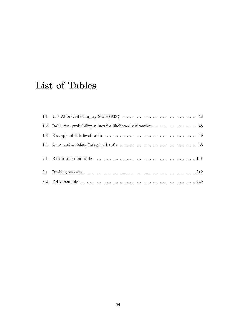
List of Tables
1.1 The Abbreviated Injury Scale (AIS) . . . . . . . . . . . . . . . . . . . . . . 48
1.2 Indicative probability values for likelihood estimation . . . . . . . . . . . . . 48
1.3 Example of risk level table . . . . . . . . . . . . . . . . . . . . . . . . . . . . 49
1.4 Automotive Safety Integrity Levels . . . . . . . . . . . . . . . . . . . . . . . 58
2.1 Risk estimation table . . . . . . . . . . . . . . . . . . . . . . . . . . . . . . . 141
3.1 Braking services . . . . . . . . . . . . . . . . . . . . . . . . . . . . . . . . . . 212
3.2 PHA example . . . . . . . . . . . . . . . . . . . . . . . . . . . . . . . . . . . 229
24
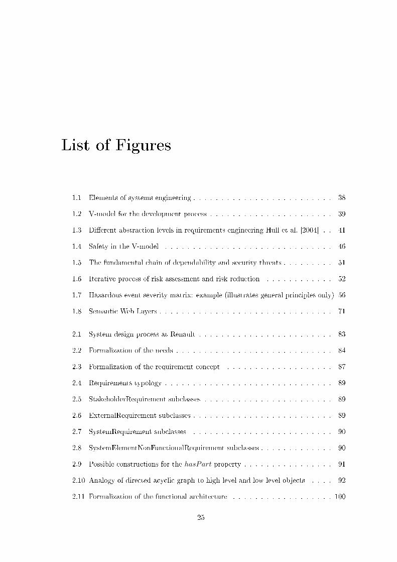
List of Figures
1.1 Elements of systems engineering . . . . . . . . . . . . . . . . . . . . . . . . . 38
1.2 V-model for the development process . . . . . . . . . . . . . . . . . . . . . . 39
1.3 Di�erent abstraction levels in requirements engineering Hull et al. [2004] . . 41
1.4 Safety in the V-model . . . . . . . . . . . . . . . . . . . . . . . . . . . . . . 46
1.5 The fundamental chain of dependability and security threats . . . . . . . . . 51
1.6 Iterative process of risk assessment and risk reduction . . . . . . . . . . . . 52
1.7 Hazardous event severity matrix: example (illustrates general principles only) 56
1.8 Semantic Web Layers . . . . . . . . . . . . . . . . . . . . . . . . . . . . . . . 71
2.1 System design process at Renault . . . . . . . . . . . . . . . . . . . . . . . . 83
2.2 Formalization of the needs . . . . . . . . . . . . . . . . . . . . . . . . . . . . 84
2.3 Formalization of the requirement concept . . . . . . . . . . . . . . . . . . . 87
2.4 Requirements typology . . . . . . . . . . . . . . . . . . . . . . . . . . . . . . 89
2.5 StakeholderRequirement subclasses . . . . . . . . . . . . . . . . . . . . . . . 89
2.6 ExternalRequirement subclasses . . . . . . . . . . . . . . . . . . . . . . . . . 89
2.7 SystemRequirement subclasses . . . . . . . . . . . . . . . . . . . . . . . . . 90
2.8 SystemElementNonFunctionalRequirement subclasses . . . . . . . . . . . . . 90
2.9 Possible constructions for the hasPart property . . . . . . . . . . . . . . . . 91
2.10 Analogy of directed acyclic graph to high level and low level objects . . . . 92
2.11 Formalization of the functional architecture . . . . . . . . . . . . . . . . . . 100
25
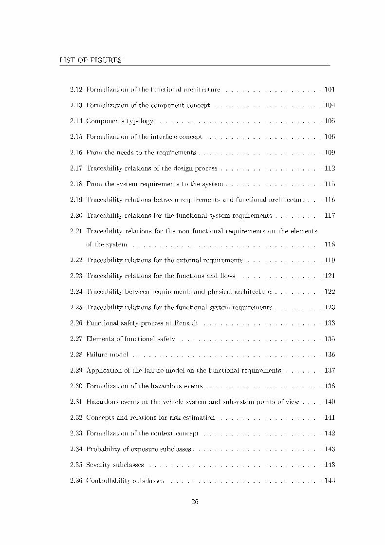
LIST OF FIGURES
2.12 Formalization of the functional architecture . . . . . . . . . . . . . . . . . . 101
2.13 Formalization of the component concept . . . . . . . . . . . . . . . . . . . . 104
2.14 Components typology . . . . . . . . . . . . . . . . . . . . . . . . . . . . . . 105
2.15 Formalization of the interface concept . . . . . . . . . . . . . . . . . . . . . 106
2.16 From the needs to the requirements . . . . . . . . . . . . . . . . . . . . . . . 109
2.17 Traceability relations of the design process . . . . . . . . . . . . . . . . . . . 112
2.18 From the system requirements to the system . . . . . . . . . . . . . . . . . . 115
2.19 Traceability relations between requirements and functional architecture . . . 116
2.20 Traceability relations for the functional system requirements . . . . . . . . . 117
2.21 Traceability relations for the non functional requirements on the elements
of the system . . . . . . . . . . . . . . . . . . . . . . . . . . . . . . . . . . . 118
2.22 Traceability relations for the external requirements . . . . . . . . . . . . . . 119
2.23 Traceability relations for the functions and �ows . . . . . . . . . . . . . . . 121
2.24 Traceability between requirements and physical architecture. . . . . . . . . . 122
2.25 Traceability relations for the functional system requirements . . . . . . . . . 123
2.26 Functional safety process at Renault . . . . . . . . . . . . . . . . . . . . . . 133
2.27 Elements of functional safety . . . . . . . . . . . . . . . . . . . . . . . . . . 135
2.28 Failure model . . . . . . . . . . . . . . . . . . . . . . . . . . . . . . . . . . . 136
2.29 Application of the failure model on the functional requirements . . . . . . . 137
2.30 Formalization of the hazardous events . . . . . . . . . . . . . . . . . . . . . 138
2.31 Hazardous events at the vehicle system and subsystem points of view . . . . 140
2.32 Concepts and relations for risk estimation . . . . . . . . . . . . . . . . . . . 141
2.33 Formalization of the context concept . . . . . . . . . . . . . . . . . . . . . . 142
2.34 Probability of exposure subclasses . . . . . . . . . . . . . . . . . . . . . . . . 143
2.35 Severity subclasses . . . . . . . . . . . . . . . . . . . . . . . . . . . . . . . . 143
2.36 Controllability subclasses . . . . . . . . . . . . . . . . . . . . . . . . . . . . 143
26
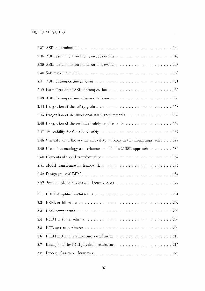
LIST OF FIGURES
2.37 ASIL determination . . . . . . . . . . . . . . . . . . . . . . . . . . . . . . . 144
2.38 ASIL assignment on the hazardous events . . . . . . . . . . . . . . . . . . . 146
2.39 ASIL assignment on the hazardous events . . . . . . . . . . . . . . . . . . . 148
2.40 Safety requirements . . . . . . . . . . . . . . . . . . . . . . . . . . . . . . . . 150
2.41 ASIL decomposition schemes . . . . . . . . . . . . . . . . . . . . . . . . . . 151
2.42 Formalization of ASIL decomposition . . . . . . . . . . . . . . . . . . . . . . 152
2.43 ASIL decomposition scheme subclasses . . . . . . . . . . . . . . . . . . . . . 153
2.44 Integration of the safety goals . . . . . . . . . . . . . . . . . . . . . . . . . . 158
2.45 Integration of the functional safety requirements . . . . . . . . . . . . . . . 159
2.46 Integration of the technical safety requirements . . . . . . . . . . . . . . . . 159
2.47 Traceability for functional safety . . . . . . . . . . . . . . . . . . . . . . . . 167
2.48 Central role of the system and safety ontology in the design approach . . . . 179
2.49 Uses of an ontology as a reference model of a MBSE approach . . . . . . . . 180
2.50 Elements of model transformation . . . . . . . . . . . . . . . . . . . . . . . . 182
2.51 Model transformation framework . . . . . . . . . . . . . . . . . . . . . . . . 184
2.52 Design process' BPM . . . . . . . . . . . . . . . . . . . . . . . . . . . . . . . 187
2.53 Spiral model of the system design process . . . . . . . . . . . . . . . . . . . 189
3.1 FREL simpli�ed architecture . . . . . . . . . . . . . . . . . . . . . . . . . . 201
3.2 FREL architecture . . . . . . . . . . . . . . . . . . . . . . . . . . . . . . . . 202
3.3 BbW components . . . . . . . . . . . . . . . . . . . . . . . . . . . . . . . . . 205
3.4 RCB functional schema . . . . . . . . . . . . . . . . . . . . . . . . . . . . . 208
3.5 RCB system perimeter . . . . . . . . . . . . . . . . . . . . . . . . . . . . . . 209
3.6 RCB functional architecture speci�cation . . . . . . . . . . . . . . . . . . . 213
3.7 Example of the RCB physical architecture . . . . . . . . . . . . . . . . . . . 215
3.8 Protégé class tab � logic view . . . . . . . . . . . . . . . . . . . . . . . . . . 220
27
LIST OF FIGURES
3.9 Protégé class tab � properties view . . . . . . . . . . . . . . . . . . . . . . . 221
3.10 Protégé properties tab . . . . . . . . . . . . . . . . . . . . . . . . . . . . . . 221
3.11 Protégé SWRL tab . . . . . . . . . . . . . . . . . . . . . . . . . . . . . . . . 222
3.12 Protégé individuals tab . . . . . . . . . . . . . . . . . . . . . . . . . . . . . . 223
3.13 RCB individual in Protégé . . . . . . . . . . . . . . . . . . . . . . . . . . . . 225
3.14 Stakeholders requirements view in ArKItect . . . . . . . . . . . . . . . . . . 226
3.15 Individuals asserted types in Protégé . . . . . . . . . . . . . . . . . . . . . . 226
3.16 Hazardous events relative to deceleration � Protégé individuals view . . . . 229
3.17 SWRL rules execution in Protégé . . . . . . . . . . . . . . . . . . . . . . . . 230
3.18 Inconsistent ontology in Protégé . . . . . . . . . . . . . . . . . . . . . . . . . 231
3.19 ASIL decomposition example � Protégé individuals visualization . . . . . . 235
3.20 RCB functional architecture view in ArKItect . . . . . . . . . . . . . . . . . 236
3.21 RCB functions listing in ArKItect . . . . . . . . . . . . . . . . . . . . . . . . 237
3.22 Flow view in ArKItect . . . . . . . . . . . . . . . . . . . . . . . . . . . . . . 237
3.23 ASIL propagation on the functional architecture example � Protégé individ-
uals visualization . . . . . . . . . . . . . . . . . . . . . . . . . . . . . . . . . 238
3.24 RCB physical architecture view in ArKItect . . . . . . . . . . . . . . . . . . 241
3.25 RCB components listing in ArKItect . . . . . . . . . . . . . . . . . . . . . . 242
3.26 Component internal view in ArKItect . . . . . . . . . . . . . . . . . . . . . . 242
3.27 ASIL propagation on the physical architecture example � Protégé individuals
visualization . . . . . . . . . . . . . . . . . . . . . . . . . . . . . . . . . . . . 243
28
General Introduction
Industrial context
For the last several years, car manufacturers have had to face an always-increasing
list of stakes and challenges. In the strongly competitive worldwide market of today, a
car manufacturer has to o�er to its customers relevant, innovative, reliable, environment-
friendly and safe services of the highest quality. All this must be done at very competitive
costs while complying with more and more stringent regulations and tighter deadlines
[Chalé Góngora et al. 2009].
We have witnessed a change in attitudes vis-à-vis the automobile product. The auto-
motive industry is intended for mass production to the contrary of other transportation
industries. The customers are numerous and di�erent by nature and they have hetero-
geneous needs. Customer needs drive the development process and serve ultimately to
validate the �nal product. Over the years, customers needs have evolved and new needs
are continuously identi�ed. As for now, a vehicle is not anymore only limited to its func-
tional role of transportation but has to propose non-functional services as well (e.g., driving
pleasure). In order to succeed (i.e., to bring in revenue), the �nal product has to either
have unanimous adoption or be highly customizable thus answering the heterogeneous
customers needs. Unanimous adoption is impossible to obtain considering contradicting
requirements (e.g., the color of a vehicle) and customization is therefore adopted with
optional services resulting in the corresponding product alternatives explosion. A status
quo can be phrased: car manufacturer survival lies on adaptability. The product has to
correspond to the ever changing customers needs. As such, car manufacturers strive for
innovations [Bishop 2008] that are optionally integrable and that will answer customers
29
GENERAL INTRODUCTION
needs or, going further, that will answer the innovation demanding market, creating new
needs that competitors will also have to address. These goals can be envisioned in the
Renault brand signature unveiled during the 2009 Frankfurt auto show: Drive the change.
The advent of mechatronics has dramatically changed the automotive landscape. Com-
pared to traditional mechanical systems, mechatronics systems tightly integrate multiple
engineering �elds i.e., mainly but not limited to, mechanical, electronic and computer sci-
ence. Mechatronics makes possible new solutions and opens possibilities for new, as yet
unknown products [Tudorache 2006], tackling innovation issues. In the automotive in-
dustry, the mechatronics paradigm adoption comes from the quick electronic revolution in
miniaturization and cost reduction. These enabled rapid growth of electronic allotment in
a vehicle, that adds up on average to more than 40% of the vehicle total price in 2010.
Electronics tour de force is termed as the increase of possible services which come without
increasing material cost, thus answering customers search of high-tech features at relatively
low cost. Software illustrates the best this state of a�airs as one only has to develop another
piece of software to o�er a new functionality. This addresses the bene�t / cost ratio issue
of new developments as new solutions are created from new de�nitions of heterogeneous,
i.e., cross-domain, components interactions. 90% of automotive innovations come from
electronics out of which 80% is actually implemented in software, thus demonstrating the
key role of mechatronics in the current automobile product. For instance, the Anti Block-
ing System (ABS) unblocks a wheel blocked during braking preserving the driver with
steering capability. Electronic Stability Program (ESP) interprets and computes driver
intended trajectory that is compared to vehicle trajectory; in case of deviation the ESP
takes action on the wheels rotation speed in order to follow computed trajectory. With
power steering one can steer the wheels e�ortlessly while at full stop. More recent and
one example that illustrates completely the bene�ts of mechatronics systems, the Renault
Active Drive System (ADS) exploits the previous mechatronics systems (i.e., ABS, ESP
and power steering) sensors and introduce only one Electronic Controller Unit (ECU), ac-
tuators on the rear wheels and control laws. This system allocates the steering function to
the four wheels improving greatly steering capability and vehicle �at turns at high speed
by the compensation of the centrifugal force for exceptional driving pleasure; that would
30
GENERAL INTRODUCTION
not have been possible otherwise. Extensive use of mechatronics and software solutions
is therefore the current trend in automotive industry and often the only solution to meet
the concurrent challenges of competitive costs, time to market and overall quality. This
trend, however, increases system complexity and consequently increases the risks due to
systematic (software process) and random (hardware) failures. These risks are of even
more serious consequences when we deal with safety-critical systems.
The emergence of the international standard IS ISO 26262 automotive standard (pub-
lished in November 2011) which deals with the functional safety of embedded Electric/Elec-
tronic systems (E/E systems) within road vehicles, brings along new requirements and con-
straints with which the systems as well as the processes allowing their development have
to comply. Although ISO 26262 is concerned with E/E systems, it provides a framework
within which safety-related systems based on other technologies can be considered. This
standard is undoubtedly acting as a catalyst for the research of new processes, methods
and tools to cope with these new requirements as it will establish a state of the art of the
requisites to guarantee functional safety. Even though ISO 26262 is not (yet) mandatory,
in case of an incident or accident, a product manufacturer is responsible before the law
to prove that its product is not the origin of the accident. This let us foretell automotive
dependability culture evolution towards this standard.
The growing complexity of automotive mechatronics systems comes mainly from the
integration of more and more elements that are heterogeneous in nature (e.g., software,
mechanical, electric, electronic) but have to work altogether in order to perform function-
alities that would not be possible without the close cooperation of di�erent �elds that
were historically treated separately. This is perfectly illustrated with the severance from
conventional automobiles to electric vehicles where electric components skyrocket while
mechanical and hydraulic systems may still be present. The consequence of the growing
complexity of automotive systems is that facing the always-increasing list of stakes and
challenges has become very complicated, thus, time-consuming and expensive given the
time scales of typical vehicle systems development cycles.
31
GENERAL INTRODUCTION
Motivation
From this context we draw the conclusion that new development processes supported
by adequate methods and tools and new methods for analyzing systems are necessary.
One of the current challenges at Renault consists in preparing its engineering divisions
so that they are capable of developing mechatronic safety-critical systems according to ISO
26262 standard. This standard de�nes a system life cycle and the activities that must be
performed in the di�erent phases of this life cycle along with the support processes that
are necessary for these activities. It also de�nes a speci�c method for automotive hazard
analysis that identi�es hazards and classi�es them using ASIL, that stands for Automotive
Safety Integrity Levels. The result of this analysis is the de�nition of the ASIL of the
hazards of the system called Safety Goals. Safety goals are allocated from the system
level to its components according to the rules de�ned by the standard. This leads to the
de�nition of speci�c safety requirements on the system, on its components and on the
associated development processes, depending on the ASIL quotation. The satisfaction of
these requirements allows asserting the absence of unacceptable residual risks.
Therefore, the standard raises some problems concerning the demonstration of func-
tional safety and, more generally, concerning the development processes which are currently
under-formalized. Indeed, one of the strengths of ISO 26262 is that each requirement in
the standard is associated to an ASIL. So, the compliance of the system, of its compo-
nents (whatever their nature), and of their development processes to the standard can be
obtained and veri�ed in a systematic way. This suggests that better formalization can be
bene�cial to ensure consistency with respect to the standard.
Research Question
In this chapter, we presented the automotive industrial context and identi�ed the pecu-
liar features of automobile systems. The conclusion is the necessity to adapt and improve
their development process. We identi�ed two areas for improvement: one, better con-
trol over the complexity of automobile mechatronics systems and, two, improvement, in
terms of power and sophistication, of the methods of analysis for automobile mechatronics
32
GENERAL INTRODUCTION
systems.
The areas of research revolves around the following fundamental question:
How can formal techniques contribute, in the continuity or in severance, to
the development process of safety-critical mechatronics systems, that have to be
compliant to ISO 26262, for a customer-oriented automobile manufacturer such
as Renault ?
In this work, we focus on formalization techniques as the whole development process
will bene�t greatly by using these techniques. By formalization techniques we are to
understand the formalization of knowledge, i.e., domain knowledge and expert knowledge,
and the more sophisticated manipulation of this structured information. These two aspects
are the subject of more targeted questions:
Q1 How can domain knowledge (i.e., automobile domain knowledge) be formalized ?
Q2 How can expert knowledge about the development process be formalized ?
Q3 How can conformance to standard ISO 26262 be veri�ed ?
Organization of the Thesis
In this work, we chose to focus on the design part of the development process where
the system fundamental elements are manipulated. In addition, the automotive industry is
confronted to the recently published international standard ISO 26262 on functional safety
which adds other activities to the design process. In the end, this work contributes to the
improvement of the design process for automotive safety critical mechatronics systems in
three ways:
1. By integrating formalization techniques for desired enrichments that are di�cult or
even impossible with currently used techniques
2. By integrating safety concepts in the current systems engineering metamodel
33
GENERAL INTRODUCTION
3. By making a highly formalized attempt in the conformance to ISO 26262 standard
Our proposal is a design process approach similar to Model Driven Engineering. The
novelty is the addition of a central ontology that formalizes a shared conceptualization
of systems engineering and functional safety. Using ontologies enables to tackle semantic
problems intrinsic to usual approaches. The ontology is used as the reference model for the
whole design process. It enables to guarantee the design process consistency not only at the
syntactic level but also at the semantic level for any environment. It is a general theoretical
approach that is applicable in any company and that has been tested at Renault.
As such, the thesis is articulated in the following manner: Chapter 1 presents the state
of the art. It goes through systems engineering and functional safety domains; Renault
design process and attempts for improvement; the main approaches used to formalize
the conceptualization in systems engineering; and ontologies as the most precise way to
formalize a conceptualization. Chapter 2 regroups our contributions: the formalization of
a conceptualization for systems engineering and functional safety, the central place of this
formalization in the design process of safety critical mechatronics systems, and a proposal
for a more precise design process named Ontology Centric Design Approach for Safety
Critical Automotive Mechatronics Systems. Chapter 3 introduces the case study of a
Regenerative Combi-Brake (RCB) system on which the design process is applied. Finally,
we give a conclusion to the thesis with a recapitulation on the contents and the future
works that are both undergoing and envisioned in re�ection to this work.
34
Chapter 1
State of the Art
Sommaire
1.1 Introduction . . . . . . . . . . . . . . . . . . . . . . . . . . . . . . 36
1.2 The Product Development Process . . . . . . . . . . . . . . . . . 36
1.2.1 Systems Engineering for Mechatronics Systems . . . . . . . . . . 37
1.2.1.1 Elements of Systems Engineering . . . . . . . . . . . . . 37
1.2.1.2 Model-Based Development . . . . . . . . . . . . . . . . 43
1.2.1.3 Conclusion . . . . . . . . . . . . . . . . . . . . . . . . . 44
1.2.2 Dependability . . . . . . . . . . . . . . . . . . . . . . . . . . . . . 45
1.2.2.1 V-model and Safety Activities . . . . . . . . . . . . . . 46
1.2.2.2 ISO/IEC Guide 51 . . . . . . . . . . . . . . . . . . . . . 47
1.2.2.3 Standards and Norms . . . . . . . . . . . . . . . . . . . 53
1.2.2.4 Conclusion . . . . . . . . . . . . . . . . . . . . . . . . . 59
1.2.3 Main Design Approaches . . . . . . . . . . . . . . . . . . . . . . 59
1.2.3.1 Simulation Based Development Process . . . . . . . . . 60
1.2.3.2 UML/SysML Based Approach . . . . . . . . . . . . . . 61
1.2.3.3 Conclusion . . . . . . . . . . . . . . . . . . . . . . . . . 65
1.2.4 Conclusion . . . . . . . . . . . . . . . . . . . . . . . . . . . . . . 66
1.3 Formalization of a Conceptualization . . . . . . . . . . . . . . . . 66
1.3.1 The Ontology Paradigm . . . . . . . . . . . . . . . . . . . . . . . 66
1.3.1.1 Basic Elements of Ontologies . . . . . . . . . . . . . . . 67
1.3.1.2 What is an Ontology . . . . . . . . . . . . . . . . . . . 68
1.3.2 Evolution of the World Wide Web towards the Semantic Web . . 70
1.3.2.1 OWL . . . . . . . . . . . . . . . . . . . . . . . . . . . . 71
1.3.2.2 SWRL . . . . . . . . . . . . . . . . . . . . . . . . . . . 73
1.3.2.3 SQWRL . . . . . . . . . . . . . . . . . . . . . . . . . . 74
1.3.3 Conclusion . . . . . . . . . . . . . . . . . . . . . . . . . . . . . . 75
1.4 Chapter Conclusion . . . . . . . . . . . . . . . . . . . . . . . . . . 75
35
1.1. INTRODUCTION
1.1 Introduction
This chapter presents the state of the art relative to our �nal objective: the improve-
ment of the design process of safety critical mechatronics systems at Renault. It is organized
in four sections. Section 1.2 presents the product development process. We present the
general domain of systems engineering that addresses the development of any system and
the dependability domain which specializes on safety critical systems. The main develop-
ment approaches are brought into the perspective with the conclusion that they are based
on particular conceptualizations. Section 1.3 presents the ontology paradigm. The funda-
mentals are explained and then we focus on the semantic web that is a growing �eld of
activity. Finally, section 1.4 concludes the state of the art on our relatively new approach to
implement semantic web technologies in the design process of safety critical mechatronics
systems at Renault.
1.2 The Product Development Process
Over the years, the automobile product has turned more complex. The general intro-
duction of this work presents the current context of the automobile product and shows
that complexi�cation is not only a trend but will amplify [Green et al. 2001]. To face this
growing complexity adequate processes, methods and tools need to be de�ned.
It is the domain of the science of systems engineering to develop a framework for orga-
nizing and conducting complex programs. Systems engineering is the solution for Renault
to position itself as a system developer. Systems engineering puts great emphasis on risk
management. The International Council On Systems Engineering (INCOSE) identi�es
two main branches of risk management: the Project Risk Management (PRM) and the
Environmental Risk Management (ERM) [INC 2011]. When dealing with safety critical
systems we are interested in the ERM branch that incorporates safety.
Section 1.2.1 presents the general systems engineering point of view that addresses the
development of any system. The development phase of the product development process
is the main point of focus. Section 1.2.2 presents the dependability domain. It is part of
systems engineering and it corresponds to additional processes, methods and tools that
36
1.2. THE PRODUCT DEVELOPMENT PROCESS
speci�cally deals with systems that are safety critical. Section 1.2.3 brie�y present the
main development approaches.
1.2.1 Systems Engineering for Mechatronics Systems
"ISO/IEC 15288 establishes a common framework for describing the life cycle of sys-
tems created by humans" [ISO 2002a]. This international standard on systems engineering
de�nes six di�erent phases that every system goes through. It starts with the conceptual-
ization of a need for the system and progresses through development, realization, utilization
and retirement of the system.
As we said, we only focus on the development phase of the life cycle. We begin by
presenting the di�erent elements of systems engineering that we manipulate. The following
de�nitions come from ISO/IEC 15288 [ISO 2002a], the INCOSE [INC 2011] and its french
chapter the "Association Française d'Ingénierie Système" (AFIS) .
1.2.1.1 Elements of Systems Engineering
The central element of systems engineering is the system.
System: An integrated set of elements that accomplish a de�ned objective. These
elements include products (hardware, software, �rmware), processes, people,
information, techniques, facilities, services, and other support elements.
More precisely, this integrated set of elements are in interaction and are organized to
accomplish a de�ned objective that would be impossible without one of these elements. A
system is easily understood in the light of the idiom "the whole is greater than the sum of
its parts". In practice, systems are products or services. The discipline developed around
the central element, i.e., the system, is systems engineering.
Systems engineering: An interdisciplinary approach and means to enable the
realization of successful systems.
To the approach, we add the collaborative characteristic that is very important (see section
1.3). The discipline can deal with many kinds of systems and in particular with the
37
1.2. THE PRODUCT DEVELOPMENT PROCESS
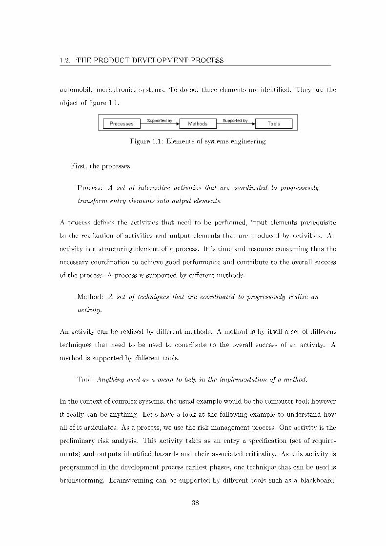
automobile mechatronics systems. To do so, three elements are identi�ed. They are the
object of �gure 1.1.
Figure 1.1: Elements of systems engineering
First, the processes.
Process: A set of interactive activities that are coordinated to progressively
transform entry elements into output elements.
A process de�nes the activities that need to be performed, input elements prerequisite
to the realization of activities and output elements that are produced by activities. An
activity is a structuring element of a process. It is time and resource consuming thus the
necessary coordination to achieve good performance and contribute to the overall success
of the process. A process is supported by di�erent methods.
Method: A set of techniques that are coordinated to progressively realize an
activity.
An activity can be realized by di�erent methods. A method is by itself a set of di�erent
techniques that need to be used to contribute to the overall success of an activity. A
method is supported by di�erent tools.
Tool: Anything used as a mean to help in the implementation of a method.
In the context of complex systems, the usual example would be the computer tool; however
it really can be anything. Let's have a look at the following example to understand how
all of it articulates. As a process, we use the risk management process. One activity is the
preliminary risk analysis. This activity takes as an entry a speci�cation (set of require-
ments) and outputs identi�ed hazards and their associated criticality. As this activity is
programmed in the development process earliest phases, one technique that can be used is
brainstorming. Brainstorming can be supported by di�erent tools such as a blackboard,
38
1.2. THE PRODUCT DEVELOPMENT PROCESS
post-it, computer spreadsheets, etc. In order to perform systems engineering, processes,
methods and tools need to be de�ned.
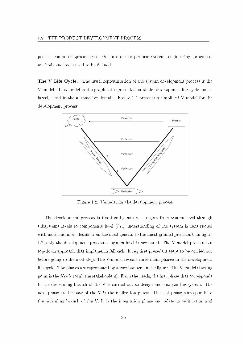
The V Life Cycle. The usual representation of the system development process is the
V-model. This model is the graphical representation of the development life cycle and is
largely used in the automotive domain. Figure 1.2 presents a simpli�ed V-model for the
development process.
Figure 1.2: V-model for the development process
The development process is iterative by nature. It goes from system level through
subsystems levels to components level (i.e., understanding of the system is constructed
with more and more details from the most general to the �nest grained precision). In �gure
1.2, only the development process at system level is presented. The V-model process is a
top-down approach that implements fallback. It requires precedent steps to be carried out
before going to the next step. The V-model reveals three main phases in the development
life cycle. The phases are represented by arrow banners in the �gure. The V-model starting
point is the Needs (of all the stakeholders). From the needs, the �rst phase that corresponds
to the descending branch of the V is carried out to design and analyze the system. The
next phase at the base of the V is the realization phase. The last phase corresponds to
the ascending branch of the V. It is the integration phase and relate to veri�cation and
39
1.2. THE PRODUCT DEVELOPMENT PROCESS
validation aspects. When carried out, it results a product that is also the ending point of
the V-model. The arrows that go from the system integration phase towards the system
design phase correspond to one important aspect of veri�cation and validation: if something
is not right in the ascending branch then something at the same level in the descending
branch is not right therefore a fallback to the descending branch is undergone.
To reduce these errors and the cost of these errors, the science of requirements engi-
neering can enforce necessary completion of a step before advancing to the next step and
identify an error at an earlier time than the integration phase.
Requirements Engineering. The most important element of the science of require-
ments engineering is the requirement.
Requirement: Characteristics that identify the accomplishment levels needed to
achieve speci�c objectives for a given set of conditions. Contractually binding
technical requirements are stated in approved speci�cations.
Actually it is the most important element in the development process. In �gure 1.2, the
process starting point are the needs of the system's stakeholders. Those needs are often not
clearly de�ned, they can be constrained by factors outside the control of the stakeholders,
or they may be in�uenced by other goals which themselves change in the course of time.
Requirements engineering is the process that initially transforms stakeholders needs into a
form that is suitable (mostly, better structured natural language) for both the development
and the communication between developers and stakeholders: the requirements. The pro-
cess continues throughout the V-model in a top-down manner, the requirements becoming
more and more accurate and corresponding to speci�c system descriptions.
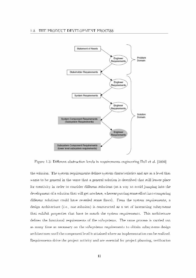
Fig 1.3 describes requirements engineering on di�erent levels.
Good practice in requirements engineering calls for the distinction between the problem
domain and the solution domain. In the problem domain, the stakeholders needs are
elaborated. In the solution domain, it is the system that will be the solution to the problem
that is elaborated. Figure 1.3 illustrates the development process and is read top-down.
Once a sound set of stakeholders requirements has been agreed upon it is time to think of
40
1.2. THE PRODUCT DEVELOPMENT PROCESS
Figure 1.3: Di�erent abstraction levels in requirements engineering Hull et al. [2004]
the solution. The system requirements de�nes system characteristics and are at a level that
wants to be general in the sense that a general solution is described that still leaves place
for creativity in order to consider di�erent solutions (as a way to avoid jumping into the
development of a solution that will get nowhere, whereas putting some e�ort into comparing
di�erent solutions could have revealed some �aws). From the system requirements, a
design architecture (i.e., one solution) is constructed as a set of interacting subsystems
that exhibit properties that have to match the system requirements. This architecture
de�nes the functional requirements of the subsystems. The same process is carried out
as many time as necessary on the subsystems requirements to obtain subsystems design
architectures until the component level is attained where an implementation can be realized.
Requirements drive the project activity and are essential for project planning, veri�cation
41
1.2. THE PRODUCT DEVELOPMENT PROCESS
(checking that the system implements the speci�cation), risk management (risks raised
against requirements can be tracked, their impact assessed and the e�ects of mitigation
and fallback understood) and change management. As a basis of every project, it is not
surprising that project failure mainly comes from the requirements that can be incomplete,
poorly expressed, poorly organized or changing too rapidly [Hull et al. 2004; Stevens et al.
1998].
In systems engineering, the support process traceability is essential as it enables to
formalize an understanding of how objectives are met.
Traceability: The ability to trace (identify and measure) all the stages that led
to a particular point in a process that consists of a chain of interrelated events.
Establishing traceability on the requirements enables to formalize a certain understand-
ing on how a system all �t together. This contributes for instance to assess the impact
of change. For example, when changing one component of a system one can retrieve all
the requirements that concern the component by tracing back and look at the impacted
elements by tracing down from the requirements. In the development process, traceabil-
ity helps in understanding the system; in the distance, it is one way to capitalize some
knowledge about the system for evolution, maintenance or reuse. We develop on this last
property as it is essential. The only realistic development approach, for both economical
reason and given the complex nature of mechatronics systems, is one based on already ex-
isting implementations by reusing elements (e.g., components, architectures, o�-the-shelf
components, etc.) of existing systems. Incremental modi�cations can then be performed
to reach the �nal solution for the new system. Reuse should therefore be favored in the
whole development process (i.e., processes, methods and tools should favor and facilitate
reuse).
Architectures Design. The other main elements that do not appear on the previous
�gures correspond to subprocesses of the design phase. In the design phase, requirements
are made more and more precise. Speci�c artifacts that correspond to some requirements
at di�erent levels of abstraction are produced. These artifacts are in the solution domain
42

1.2. THE PRODUCT DEVELOPMENT PROCESS
of �gure 1.3. Two abstraction levels are considered. First, at functional level, the system's
functional (or logical) architecture is designed. It is a solution of the system which is
independent from implementation choices. This solution describes system's functions and
how these functions interact with one another.
Function: A task, action, or activity that must be accomplished to achieve a
desired outcome.
Second, at component level, the system's physical architecture is designed to be one par-
ticular solution for the functional architecture. It describes how functional architecture's
functions can be implemented into physical components and component's interfaces that
enable components interaction.
Component: A modular part of a system that encapsulates its contents and
whose manifestation is replaceable within its environment. A component de�nes
its behavior in terms of provided and required interfaces. As such, a component
serves as a type, whose conformance is de�ned by these provided and required
interfaces (encompassing both their static as well as dynamic semantics).
The general notion of �ow is introduced as the mean to represent functions and components
interconnection.
Flow: Non-broken circulation of information, energy or material.
We do not give more detail on architectures design however it can be noted that these
architectures are mainly de�ned using block diagram notation that uses blocks to represent
functions or components and arrows to represent �ows. Naturally, traceability is established
between requirements and their corresponding architectural elements.
1.2.1.2 Model-Based Development
Mechatronics is an engineering science, in which the functionality of a technical system
is realized by a tight interaction of mechanical, electronic and computer science engineering
�elds.
43
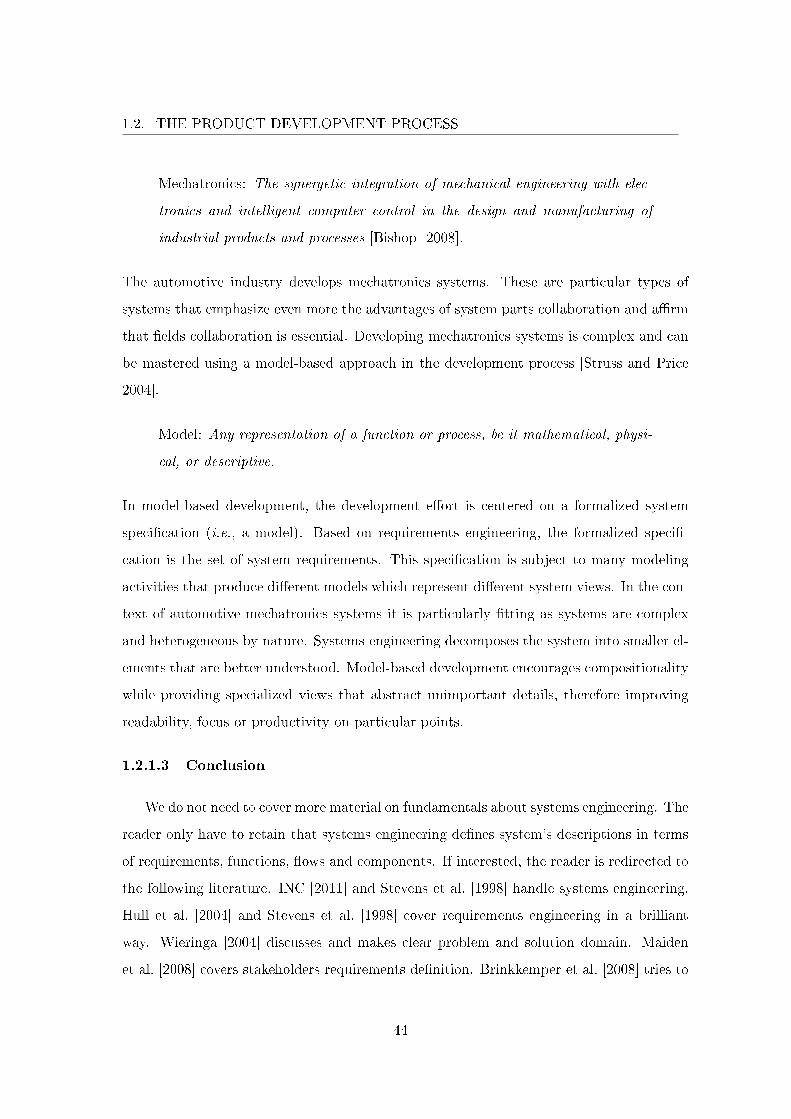
1.2. THE PRODUCT DEVELOPMENT PROCESS
Mechatronics: The synergetic integration of mechanical engineering with elec-
tronics and intelligent computer control in the design and manufacturing of
industrial products and processes [Bishop 2008].
The automotive industry develops mechatronics systems. These are particular types of
systems that emphasize even more the advantages of system parts collaboration and a�rm
that �elds collaboration is essential. Developing mechatronics systems is complex and can
be mastered using a model-based approach in the development process [Struss and Price
2004].
Model: Any representation of a function or process, be it mathematical, physi-
cal, or descriptive.
In model-based development, the development e�ort is centered on a formalized system
speci�cation (i.e., a model). Based on requirements engineering, the formalized speci�-
cation is the set of system requirements. This speci�cation is subject to many modeling
activities that produce di�erent models which represent di�erent system views. In the con-
text of automotive mechatronics systems it is particularly �tting as systems are complex
and heterogeneous by nature. Systems engineering decomposes the system into smaller el-
ements that are better understood. Model-based development encourages compositionality
while providing specialized views that abstract unimportant details, therefore improving
readability, focus or productivity on particular points.
1.2.1.3 Conclusion
We do not need to cover more material on fundamentals about systems engineering. The
reader only have to retain that systems engineering de�nes system's descriptions in terms
of requirements, functions, �ows and components. If interested, the reader is redirected to
the following literature. INC [2011] and Stevens et al. [1998] handle systems engineering.
Hull et al. [2004] and Stevens et al. [1998] cover requirements engineering in a brilliant
way. Wieringa [2004] discusses and makes clear problem and solution domain. Maiden
et al. [2008] covers stakeholders requirements de�nition. Brinkkemper et al. [2008] tries to
44
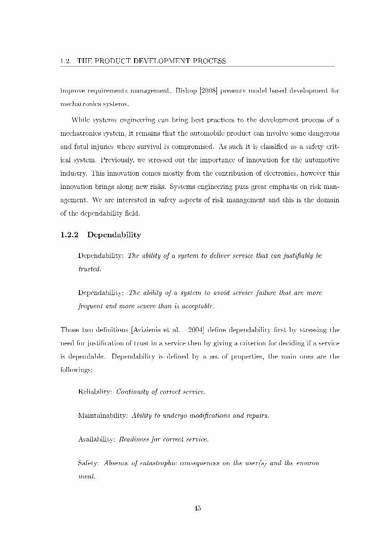
1.2. THE PRODUCT DEVELOPMENT PROCESS
improve requirements management. Bishop [2008] presents model-based development for
mechatronics systems.
While systems engineering can bring best practices to the development process of a
mechatronics system, it remains that the automobile product can involve some dangerous
and fatal injuries where survival is compromised. As such it is classi�ed as a safety crit-
ical system. Previously, we stressed out the importance of innovation for the automotive
industry. This innovation comes mostly from the contribution of electronics, however this
innovation brings along new risks. Systems engineering puts great emphasis on risk man-
agement. We are interested in safety aspects of risk management and this is the domain
of the dependability �eld.
1.2.2 Dependability
Dependability: The ability of a system to deliver service that can justi�ably be
trusted.
Dependability: The ability of a system to avoid service failure that are more
frequent and more severe than is acceptable.
Those two de�nitions [Avizienis et al. 2004] de�ne dependability �rst by stressing the
need for justi�cation of trust in a service then by giving a criterion for deciding if a service
is dependable. Dependability is de�ned by a set of properties, the main ones are the
followings:
Reliability: Continuity of correct service.
Maintainability: Ability to undergo modi�cations and repairs.
Availability: Readiness for correct service.
Safety: Absence of catastrophic consequences on the user(s) and the environ-
ment.
45
1.2. THE PRODUCT DEVELOPMENT PROCESS
The interested reader can consult [Avizienis et al. 2004] for the de�nitions relative to
dependability domain. We are interested in safety aspects in the development process the
objective being the proof of a safe system.
1.2.2.1 V-model and Safety Activities
As can be seen in �gure 1.4, dependability studies are carried out in a second V cycle
that is executed in parallel to the development process.
Figure 1.4: Safety in the V-model
This layout results from usual organization that commits dependability studies to a
team that is independent of the design team. The safety team has to demonstrate that the
system is dependable. Most often, the time lapse between design studies and dependability
studies is very, not to say too much, important. For instance, if a problem appears in the
dependability studies that are systematically based on design activities, the development
team needs to go back on the impaired activities. We advocate that important improvement
of the development process lies in a better coordination or combination of both design and
dependability teams. This is shown in �gure 1.4 as we placed the dependability V-model
in parallel to the development process but somewhat earlier by placing it higher. In fact,
dependability studies should be performed earlier than the design phase of the development
process [Boulanger 2006].
Now that we understand the place of dependability studies in the development process,
we de�ne some fundamental elements of the safety �eld.
46
1.2. THE PRODUCT DEVELOPMENT PROCESS
1.2.2.2 ISO/IEC Guide 51
The international standard ISO/IEC Guide 51 [ISO 1999] covers safety aspects for
their inclusion in standards. We will present the notions of undesired consequences and
come back on their causes. Then we will present risk management as a way to improve
safety.
Fundamentals. From the notion of harm, it is possible to de�ne risk, safety and all
associated concepts such as hazards and hazardous events.
The ultimate unwanted outcome when using a vehicle is harm. This concept is shared
in many domains (e.g., nuclear, transportation, and medical technology), and is applicable
to every application domain of automobile. Harm is de�ned as:
Harm: Physical injury or damage to the health of people, or damage to property
or the environment.
Three attributes of harm are usually de�ned: nature of the harm, its severity and its
probability of occurrence. In the case of an automobile in physical interaction with humans,
the �rst potential harm generally considered is damage to the health of people due to vehicle
crashes, but many other potential harms exist (electrocution, stressful conditions for users,
etc.).
Severity is used to denote the degree of harm and is usually expressed as a qualitative
level. Many severity indexes can be used (coming from other domains). These indexes
express severity levels in terms of impact forces, kinetic energy, acceleration, speed, etc.
table 1.1 is used in automotive applications and gives a generic severity scale [AAAM
1998].
A more controversial concept is the notion of probability of occurrence or likelihood of
harm. Indeed, this metric was historically used for hardware systems where it is possible to
evaluate failure rates (and then, the probability of occurrence of the failure and its outcome)
based on test-bed results. Due to the growth of software, this quantitative evaluation is
not yet possible for today's systems. It is also noted that some standards (e.g. in the
47

1.2. THE PRODUCT DEVELOPMENT PROCESS
AIS Severity Type of injury0 None None1 Minor Super�cial injury2 Moderate Recoverable3 Serious Possibly recoverable4 Severe Not fully recoverable without care5 Critical Not fully recoverable with care6 Fatal Not survivable
Table 1.1: The Abbreviated Injury Scale (AIS)
domain of medical devices) state that "...a good qualitative description is preferable to a
quantitative inaccuracy" [ISO 2000]. Nevertheless, levels can sometimes be associated to
di�erent quantitative evaluation in order to give indications to designers. This choice is
strongly related to the considered application, and no generic values exist. An example of
levels is given in table 1.2. The levels graduate from high risk, intermediate risk, low risk
and negligible risk.
Likelihood Indicative probability (per year)Frequent > 1
Probable 1− 10−1
Occasional 10−1 − 10−2
Rare 10−2 − 10−6
Impossible > 10−6
Table 1.2: Indicative probability values for likelihood estimation
Risk of harm is de�ned as:
Risk: Combination of the probability of occurrence of harm and the severity of
that harm.
This de�nition is sometime extended with other metrics such as likelihood of exposure of
the user to the system, but most studies de�ne a risk level for each pair of qualitative
levels (likelihood, severity). Table 1.3 is an example of possible risk values with a classic
graduation.
The main objective of such a de�nition of risk levels is to identify risks deemed to be
tolerable:
48
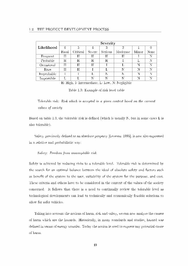
1.2. THE PRODUCT DEVELOPMENT PROCESS
LikelihoodSeverity
6 5 4 3 2 1 0Fatal Critical Severe Serious Moderate Minor None
Frequent H H H H H I NProbable H H H H I L NOccasional H H H I L N N
Rare H H I L N N NImprobable I I L N N N NImpossible L L N N N N N
H: High, I: Intermediate, L: Low, N: Negligible
Table 1.3: Example of risk level table
Tolerable risk: Risk which is accepted in a given context based on the current
values of society.
Based on table 1.3, the tolerable risk is de�ned (which is usually N, but in some cases L is
also tolerable).
Safety, previously de�ned as an absolute property [Leveson 1995], is now also expressed
in a relative and probabilistic way:
Safety: Freedom from unacceptable risk.
Safety is achieved by reducing risks to a tolerable level. Tolerable risk is determined by
the search for an optimal balance between the ideal of absolute safety and factors such
as bene�t of the system to the user, suitability of the system for the purpose, and cost.
These criteria and others have to be considered in the context of the values of the society
concerned. It follows that there is a need to continually review the tolerable level as
technological developments can lead to technically and economically feasible solutions to
allow for safer vehicles.
Taking into account the notions of harm, risk and safety, we can now analyze the causes
of harm which are the hazards. Historically, in many standards and studies, hazard was
de�ned in terms of energy transfer. Today the notion is used to express any potential cause
of harm.
49
1.2. THE PRODUCT DEVELOPMENT PROCESS
Hazard: Potential source of harm.
A hazard can be a failure, a human error, a variable lighting condition (which is an adverse
situation for a driver), etc. Often a hazard can indicate the origin or nature of harm when
it gives information about the source (e.g., electric shock hazard, crushing hazard, driver
focus hazard, etc.). In many cases, an accident is the combination of the presence of a
hazard and a situation where humans are exposed to this hazard. This concept is de�ned
by the term hazardous situation:
Hazardous situation: Circumstance in which people, property or the environ-
ment are exposed to one or more hazards.
The term situation integrates the notion of scenario, i.e., the description of environment
conditions, system state, and actions performed during the scenario. A hazardous situation
does not necessarily lead to an accident. Hence the concepts of harmful event and incident:
Harmful event: Occurrence in which a hazardous situation results in harm.
Incident: Event that does not lead to harm, but which has the potential to create
harm in other circumstances.
From those two de�nitions the notion of event appears. From a system point of view that
is broader than the safety one, the notion of feared event that includes but does not limit
to harm is introduced:
Feared Event: Event that must not occur or that must occur with low probability.
In order for these events to not occur, or to hardly occur, one has to understand how they
can occur. Dependability of a complex system can be undermined by three types of events:
failures, errors and faults [Avizienis et al. 2004]. Elements of a system are subject to
failures that can bring to a hazardous situation.
Failure: ... event that occurs when the delivered service deviates from correct
service.
50
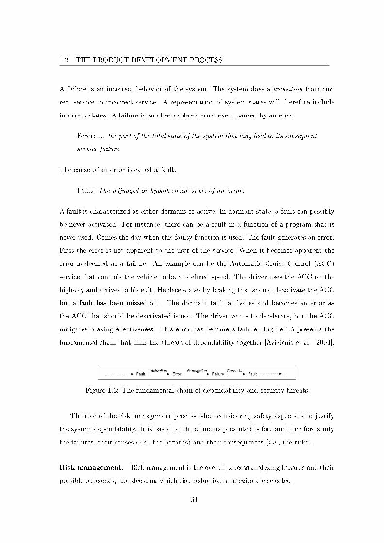
1.2. THE PRODUCT DEVELOPMENT PROCESS
A failure is an incorrect behavior of the system. The system does a transition from cor-
rect service to incorrect service. A representation of system states will therefore include
incorrect states. A failure is an observable external event caused by an error.
Error: ... the part of the total state of the system that may lead to its subsequent
service failure.
The cause of an error is called a fault.
Fault: The adjudged or hypothesized cause of an error.
A fault is characterized as either dormant or active. In dormant state, a fault can possibly
be never activated. For instance, there can be a fault in a function of a program that is
never used. Comes the day when this faulty function is used. The fault generates an error.
First the error is not apparent to the user of the service. When it becomes apparent the
error is deemed as a failure. An example can be the Automatic Cruise Control (ACC)
service that controls the vehicle to be at de�ned speed. The driver uses the ACC on the
highway and arrives to his exit. He decelerates by braking that should deactivate the ACC
but a fault has been missed out. The dormant fault activates and becomes an error as
the ACC that should be deactivated is not. The driver wants to decelerate, but the ACC
mitigates braking e�ectiveness. This error has become a failure. Figure 1.5 presents the
fundamental chain that links the threats of dependability together [Avizienis et al. 2004].
Figure 1.5: The fundamental chain of dependability and security threats
The role of the risk management process when considering safety aspects is to justify
the system dependability. It is based on the elements presented before and therefore study
the failures, their causes (i.e., the hazards) and their consequences (i.e., the risks).
Risk management. Risk management is the overall process analyzing hazards and their
possible outcomes, and deciding which risk reduction strategies are selected.
51
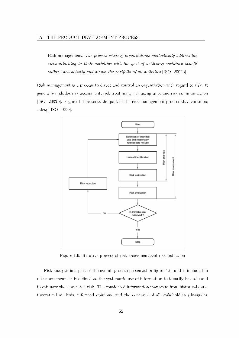
1.2. THE PRODUCT DEVELOPMENT PROCESS
Risk management: The process whereby organizations methodically address the
risks attaching to their activities with the goal of achieving sustained bene�t
within each activity and across the portfolio of all activities [ISO 2002b].
Risk management is a process to direct and control an organization with regard to risk. It
generally includes risk assessment, risk treatment, risk acceptance and risk communication
[ISO 2002b]. Figure 1.6 presents the part of the risk management process that considers
safety [ISO 1999].
Figure 1.6: Iterative process of risk assessment and risk reduction
Risk analysis is a part of the overall process presented in �gure 1.6, and is included in
risk assessment. It is de�ned as the systematic use of information to identify hazards and
to estimate the associated risk. The considered information may stem from historical data,
theoretical analysis, informed opinions, and the concerns of all stakeholders (designers,
52
1.2. THE PRODUCT DEVELOPMENT PROCESS
end users, regulatory authority, etc.). During risk analysis, various methods can be used to
handle functional and technological issues, for example: HAZOP-like techniques (HAZard
OPerability), Failure Modes, E�ects, and Criticality Analysis (FMECA), and Fault Tree
Analysis (FTA). These are the three main techniques, and have been widely used in many
domains. They are also recommended in many standards on dependability. During the risk
reduction step, actions are taken to reduce the probability and/or the negative consequences
associated to a risk. The means to attain dependability can be grouped in four major
categories:
• "Fault prevention" means to prevent the occurrence or introduction of faults.
• "Fault tolerance" means to avoid service failures in the presence of faults.
• "Fault removal" means to reduce the number and severity of faults.
• "Fault forecasting" means to estimate the present number, the future incidence, and
the likely consequences of faults.
The establishment of dependability therefore requires the selection of suitable means
that can justify this dependability. Once all identi�ed risks on the project are controlled,
the system can be stated dependable.
1.2.2.3 Standards and Norms
Renault is confronted to three di�erent types of standards. First, the regulations.
Regulations are constraints that have to be respected for a vehicle to be commercialized
in a country. It is essential for a constructor to consider this type of standard. The
next two types of standards are characterized by the external / internal criterion. A
constructor is interested in external standards as they establish a state of the art on a
speci�c subject. Keeping an eye out for new, more e�cient technologies, processes, methods
or tools that will bene�t the industry is not only essential but common sense. An external
standard can be normative but we class it under regulation type. Non normative standards
are categorized under external standards. Finally, an internal standard a�ects all the
actors inside the industry and even the partners, be they associates, suppliers or others.
53

1.2. THE PRODUCT DEVELOPMENT PROCESS
Those internal standards implement regulations and external standards while at the same
time making abstraction of inconsequential elements. Often, they are used for quality
department that evaluates application of good practice. Those evaluations are part of the
veri�cation activities. We do not distinguish between standards and norms; the two terms
are used indi�erently throughout this report.
Even though consideration of an external standard is by no mean mandatory, when
dealing with safety critical systems, if a catastrophic consequence (on a user of the system
or the environment) that comes from any system element happens, this catastrophic event
justi�es by itself the need to take into account any standard that deals with the domain
considered. The consequence is so enormous that if it can be avoided then it has to. In
this section we present only the external standards that are in relation to the automotive
industry.
IEC 61508. IEC 61508 is an international generic standard for the functional safety of
programmable electrical, electronic and programmable electronic (E/E/PE) safety-related
systems [IEC 2000]. System safety is achieved by reducing risks to a tolerable level.
Tolerable risk is determined by the search for an optimal balance between the ideal of
absolute safety and of factors such as: bene�t of the system to the user, suitability of
the system for the purpose, and cost. These criteria and others have to be considered
in the context of the values of the society concerned. It follows that there is a need to
continually review the tolerable level as technological developments can lead to technically
and economically feasible solutions to allow for safer systems.
The standard de�nes a safety function as a function to be implemented by any techno-
logical means which is a risk reduction strategy. The standard IEC 61508 was originally
developed for machine systems, where safety of equipment under control (like a machine
with a sharp blade) is guaranteed by independent safety systems such as fences or inter-
locking devices. Such independent systems are called safety-related systems in the IEC
61508 standard. In the case of a vehicle it is also possible to apply these concepts because
the vehicle itself can be considered as the equipment under control. In that case, safety
related systems can be assigned Safety Integrity Levels (SIL) using the standard. Safety
54
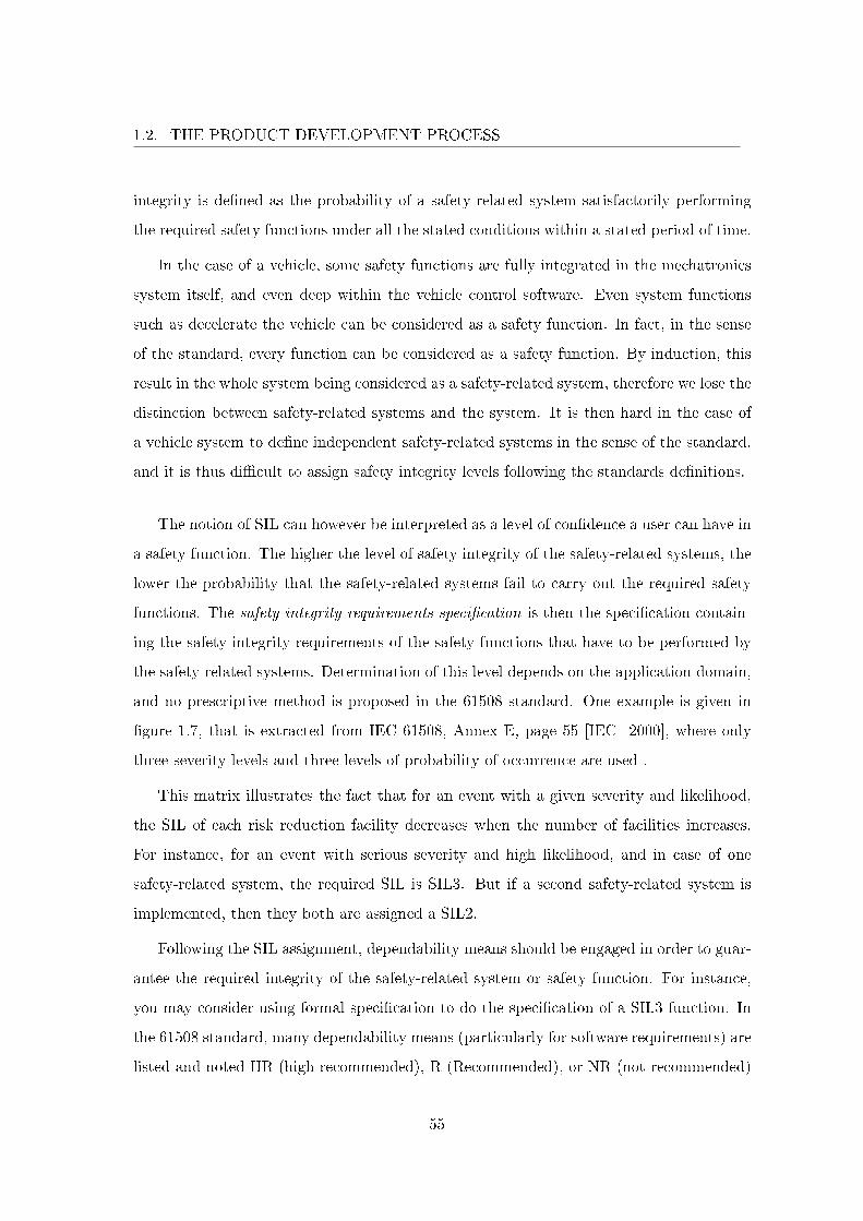
1.2. THE PRODUCT DEVELOPMENT PROCESS
integrity is de�ned as the probability of a safety-related system satisfactorily performing
the required safety functions under all the stated conditions within a stated period of time.
In the case of a vehicle, some safety functions are fully integrated in the mechatronics
system itself, and even deep within the vehicle control software. Even system functions
such as decelerate the vehicle can be considered as a safety function. In fact, in the sense
of the standard, every function can be considered as a safety function. By induction, this
result in the whole system being considered as a safety-related system, therefore we lose the
distinction between safety-related systems and the system. It is then hard in the case of
a vehicle system to de�ne independent safety-related systems in the sense of the standard,
and it is thus di�cult to assign safety integrity levels following the standards de�nitions.
The notion of SIL can however be interpreted as a level of con�dence a user can have in
a safety function. The higher the level of safety integrity of the safety-related systems, the
lower the probability that the safety-related systems fail to carry out the required safety
functions. The safety integrity requirements speci�cation is then the speci�cation contain-
ing the safety integrity requirements of the safety functions that have to be performed by
the safety-related systems. Determination of this level depends on the application domain,
and no prescriptive method is proposed in the 61508 standard. One example is given in
�gure 1.7, that is extracted from IEC 61508, Annex E, page 55 [IEC 2000], where only
three severity levels and three levels of probability of occurrence are used .
This matrix illustrates the fact that for an event with a given severity and likelihood,
the SIL of each risk reduction facility decreases when the number of facilities increases.
For instance, for an event with serious severity and high likelihood, and in case of one
safety-related system, the required SIL is SIL3. But if a second safety-related system is
implemented, then they both are assigned a SIL2.
Following the SIL assignment, dependability means should be engaged in order to guar-
antee the required integrity of the safety-related system or safety function. For instance,
you may consider using formal speci�cation to do the speci�cation of a SIL3 function. In
the 61508 standard, many dependability means (particularly for software requirements) are
listed and noted HR (high recommended), R (Recommended), or NR (not recommended)
55
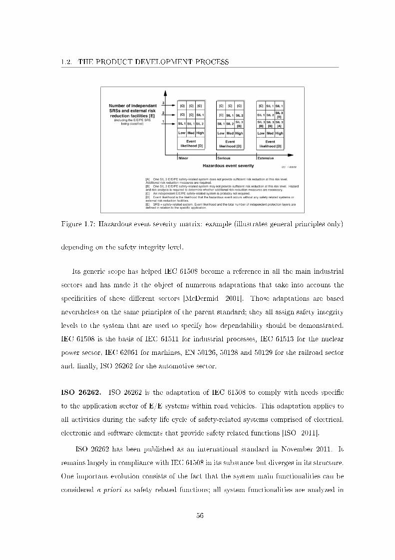
1.2. THE PRODUCT DEVELOPMENT PROCESS
Figure 1.7: Hazardous event severity matrix: example (illustrates general principles only)
depending on the safety integrity level.
Its generic scope has helped IEC 61508 become a reference in all the main industrial
sectors and has made it the object of numerous adaptations that take into account the
speci�cities of these di�erent sectors [McDermid 2001]. Those adaptations are based
nevertheless on the same principles of the parent standard; they all assign safety integrity
levels to the system that are used to specify how dependability should be demonstrated.
IEC 61508 is the basis of IEC 61511 for industrial processes, IEC 61513 for the nuclear
power sector, IEC 62061 for machines, EN 50126, 50128 and 50129 for the railroad sector
and, �nally, ISO 26262 for the automotive sector.
ISO 26262. ISO 26262 is the adaptation of IEC 61508 to comply with needs speci�c
to the application sector of E/E systems within road vehicles. This adaptation applies to
all activities during the safety life cycle of safety-related systems comprised of electrical,
electronic and software elements that provide safety related functions [ISO 2011].
ISO 26262 has been published as an international standard in November 2011. It
remains largely in compliance with IEC 61508 in its substance but diverges in its structure.
One important evolution consists of the fact that the system main functionalities can be
considered a priori as safety related functions; all system functionalities are analyzed in
56
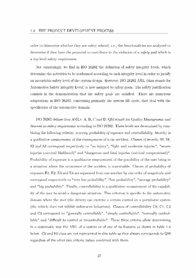
1.2. THE PRODUCT DEVELOPMENT PROCESS
order to determine whether they are safety related, i.e., the functionalities are analyzed to
determine if they have the potential to contribute to the violation of a safety goal which is
a top level safety requirement.
Not surprisingly, we �nd in ISO 26262 the de�nition of safety integrity levels, which
determine the activities to be performed according to each integrity level in order to justify
an acceptable safety level of the system design. However, ISO 26262 ASIL (that stands for
Automotive Safety Integrity Level) is now assigned to safety goals. The safety justi�cation
consists in the demonstration that the safety goals are satis�ed. There are numerous
adaptations in ISO 26262, concerning primarily the system life cycle, that deal with the
speci�cities of the automotive domain.
ISO 26262 de�nes four ASILs: A, B, C and D. QM stands for Quality Management and
denotes no safety requirement according to ISO 26262. These levels are determined by com-
bining the following criteria: severity, probability of exposure and controllability. Severity is
a qualitative measurement of the consequences of a car accident. Classes of severity S0, S1,
S2 and S3 correspond respectively to "no injury", "light and moderate injuries", "severe
injuries (survival likelihood)" and "dangerous and fatal injuries (survival compromised)".
Probability of exposure is a qualitative measurement of the possibility of the user being in
a situation where the occurrence of the accident is conceivable. Classes of probability of
exposure E1, E2, E3 and E4 are separated from one another by one order of magnitude and
correspond respectively to "very low probability", "low probability", "average probability"
and "big probability". Finally, controllability is a qualitative measurement of the capabil-
ity of the user to avoid a dangerous situation. This criterion is speci�c to the automotive
domain where the user (the driver) can exercise a certain control on a permissive system
(the vehicle does not inhibit unforeseen behaviors). Classes of controllability C0, C1, C2
and C3 correspond to "generally controllable", "simply controllable", "normally control-
lable" and "di�cult to control or uncontrollable". These three criteria allow determining
in a systematic way the ASIL of a system or of one of its features as shown in table 1.4
below. C0 and E0 class are not represented in this table as they always corresponds to QM
regardless of the other two criteria values combined with them.
57
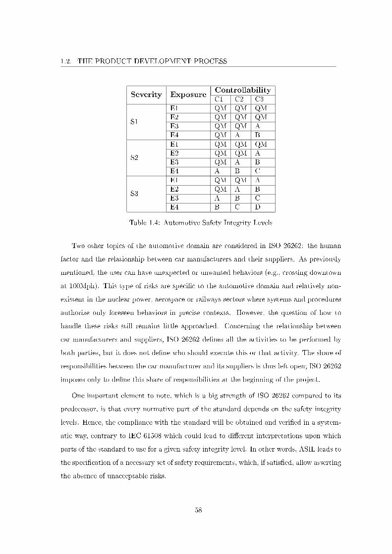
1.2. THE PRODUCT DEVELOPMENT PROCESS
Severity ExposureControllabilityC1 C2 C3
S1
E1 QM QM QME2 QM QM QME3 QM QM AE4 QM A B
S2
E1 QM QM QME2 QM QM AE3 QM A BE4 A B C
S3
E1 QM QM AE2 QM A BE3 A B CE4 B C D
Table 1.4: Automotive Safety Integrity Levels
Two other topics of the automotive domain are considered in ISO 26262: the human
factor and the relationship between car manufacturers and their suppliers. As previously
mentioned, the user can have unexpected or unwanted behaviors (e.g., crossing downtown
at 100Mph). This type of risks are speci�c to the automotive domain and relatively non-
existent in the nuclear power, aerospace or railways sectors where systems and procedures
authorize only foreseen behaviors in precise contexts. However, the question of how to
handle these risks still remains little approached. Concerning the relationship between
car manufacturers and suppliers, ISO 26262 de�nes all the activities to be performed by
both parties, but it does not de�ne who should execute this or that activity. The share of
responsibilities between the car manufacturer and its suppliers is thus left open; ISO 26262
imposes only to de�ne this share of responsibilities at the beginning of the project.
One important element to note, which is a big strength of ISO 26262 compared to its
predecessor, is that every normative part of the standard depends on the safety integrity
levels. Hence, the compliance with the standard will be obtained and veri�ed in a system-
atic way, contrary to IEC 61508 which could lead to di�erent interpretations upon which
parts of the standard to use for a given safety integrity level. In other words, ASIL leads to
the speci�cation of a necessary set of safety requirements, which, if satis�ed, allow asserting
the absence of unacceptable risks.
58
1.2. THE PRODUCT DEVELOPMENT PROCESS
1.2.2.4 Conclusion
Functional safety has been presented as part of the product development process to
address critical systems. The interested reader can refer to Avizienis et al. [2004] that
is the reference on dependability. ISO [1999] and ISO [2002b] are guidelines to include
risk management and safety aspects in standards. Among other, they de�ne a vocabulary
for safety. INC [2011] presents the risk management process in the systems engineering
development process. Leveson [1995] presents system safety, i.e., safety for systems en-
gineering. Herrmann [1999], McDermid [2001] discuss standards on safety prior to ISO
26262. International standards IEC [2000] and ISO [2011] on functional safety for E/E/PE
systems which concern the automobile industry. The emergence of ISO 26262 international
standard in the automotive industry can be perceived either as a source of concern and
apprehension, or as an opportunity to improve current systems engineering processes and
working methods. Either way, this standard is undoubtedly acting as a catalyst for the
research of new processes, methods and tools to cope with these new requirements. The
new processes, methods and tools that address functional safety mainly innovate on safety
studies that correspond to risk analysis step in the overall risk management process. In
this thesis, we are literally only interested in the design activity. Therefore, the di�erent
analyses that bring information that results in informed design decisions are not supported
and not presented. Similarly, design approaches that address functional safety are not
relevant and the next section presents a state of the art on the di�erent design approaches
which mostly are inconsiderate of functional safety but nonetheless adapted for the design
of any system.
1.2.3 Main Design Approaches
As a general de�nition, a design approach (or method or methodology) refers to a cod-
i�ed conceptualization which helps to systematically create a set of interrelated artifacts
that ultimately lead to the sought after system. We will return in section 1.3 on the notion
of conceptualization (for interrelated artifacts) which is the fundamental issue that con-
cerns all existing approaches that we address in this work. For now this section identi�es
and brie�y describes the main design approaches for systems engineering (that includes
59
1.2. THE PRODUCT DEVELOPMENT PROCESS
functional safety design). Section 1.2.3.1 presents the main development process of mecha-
tronics systems in the automotive industry. Section 1.2.3.2 brie�y presents approaches
based on the standards de facto UML and its adaptation to systems engineering, SysML.
Finally, section 1.2.3.3 gives the conclusion on the design approaches and the automotive
industry context.
1.2.3.1 Simulation Based Development Process
The V-model (see �gure 1.2) is currently the standard de facto used in the automotive
industry for the development of mechatronics systems. It has been adapted to detect
design issues before the system integration phase and to automate some activities tackling
issues such as short development time constraints and cost of error (detected too late). In
this approach, models are introduced to answer the requirements beginning at architecture
design phase. At this point, the remaining of the development process is model based. The
architecture models are executable (the most widely used simulation tool for mechatronics
systems that include software is Matlab/Simulink). Design veri�cation is based on testing
and is �rst done on architecture models before the realization phase of the V in a simulated
environment (Model In the Loop or MIL). Some tests are generated automatically from
models and the same tests are reused for di�erent abstraction levels of the integration
phase. Software code, executed on particular hardware platforms, can also be generated
automatically. It is veri�ed in a simulated environment (Software In the Loop or SIL)
so that implementation on hardware and integration are initiated on solid basis. Finally,
the simulated hardware is replaced with its physical realization and tested in simulation
(Hardware In the Loop or HIL).
In this approach requirements management and traceability are done with additional
tool support. These activities can be somewhat imprecise. These issues are considered
in our approach and resolved at the semantic level (i.e., we give meaning to tracing a
requirement to a design element).
60
1.2. THE PRODUCT DEVELOPMENT PROCESS
1.2.3.2 UML/SysML Based Approach
UML (Uni�ed Modeling Language) [UML 2007], often wrongly considered as an ap-
proach, is a graphical notation considered as a semi-formal language which is the basis of
many approaches. As UML is mostly better suited with software engineering, the general
purpose language SysML (Systems Modeling Language) [Sys 2007] has been standardized
to address systems engineering. It is speci�ed as a pro�le (i.e., a dialect) of UML and
de�nes in particular requirements as a conceptual class of the language. SysML based ap-
proaches are of the same kinds as UML based ones. We identify three kinds of approaches.
As the two standards position themselves as general purpose language, they should be
viewed as the common frame of development best practices. Therefore they should be
adapted depending on the domain. The �rst kind of approaches ignores this adaptation.
SysML is left aside for these kind of approaches as it is by nature an adaptation to systems
engineering. For instance, it is adapted for requirements engineering which is speci�cally
addressed by our approach. Second kind of approaches uses extensibility mechanisms to
better suit the speci�cities of a domain but leaves syntax and semantic informal. The last
kind of approaches rise at a higher abstraction level to de�ne their own language with its
semantic that remains however informal.
Uni�ed Process. Uni�ed Process or UP [Booch et al. 2005] approaches (e.g., Rational
Uni�ed Process or RUP) are often used in very large software projects. Characteristics of
UP are iterative, incremental, architecture centric, use case driven and risk focused (any
risk type including risk of harm). Concerning design, UP addresses three activities with
respective models. The de�nition of the needs activity corresponds to the elaboration of
requirements. Functional requirements are modeled with UML use case diagrams. Non
functional requirements are not considered. Then, analysis of needs activity produces spec-
i�cations assumed to provide a correct understanding of the needs. Here, the needs refer
to use cases which are speci�ed using UML sequence and interaction overview diagrams.
Finally, design activity gives a thorough understanding on components (read architectural
elements) interaction and their internal behavior with UML class, activity and state ma-
chine diagrams for instance.
61
1.2. THE PRODUCT DEVELOPMENT PROCESS
As mentioned, even though UP approaches should be viewed as the common frame of
development best practices and should be adapted depending on the domain, it is often
viewed as a universal process and used as is. Here UP is presented as an example for
approaches that are imprecise in the sense that important conceptual elements are not
considered as such (for example, to the notion of need, one has to understand requirements
or use cases). With UML, the requirements are not considered as a conceptual class and
therefore requirements traceability is not supported.
OOSEM. OOSEM (Object-Oriented Systems Engineering Method) [Lykins et al. 2000]
is promoted by the systems engineering community and is a reference for systems devel-
opment. OOSEM is a modeling method based on UML. It implements UML extensibility
mechanisms that di�erentiate with the previous kind of UML based approaches. UML
extensibility mechanisms are used so that the modeling language can be made more pre-
cise, however, with no additional syntax nor semantic. OOSEM uses stereotyping (i.e.,
an extensibility mechanism) of UML modeling elements to represent systems engineering
concepts such as the system or logical components for instance. It has four core design
activities: analyze needs, de�ne system requirements, de�ne logical architecture and syn-
thetize candidate allocated architectures. Analyze needs results in use cases, scenario
descriptions, static system model with external interacting systems. UML use case, se-
quence and class diagrams are used. The systems requirements are represented with a
UML class diagram that represents the system as a black box with its inputs, outputs
and external collaborators. Another class diagram is used to represent the hierarchy of
logical components as an aggregation hierarchy of stereotyped classes. Finally, any means
of UML can be used to represent the allocation or realization components to the logical
ones. Even though OOSEM promotes requirements traceability, this is not supported by
the formalism it uses, therefore it is supported externally by means of a Requirements and
Veri�cation Traceability database (RVT).
Here, we presented OOSEM as it was practiced before the introduction of SysML to
illustrate extensibility mechanisms that enable to consider the logical components as a con-
ceptual class for instance. SysML does so by default, however, the point is that by means
62
1.2. THE PRODUCT DEVELOPMENT PROCESS
of extensibility mechanisms, other concepts can be made more precise in UML/SysML. For
instance, mechatronics systems basic components are sensors, calculators and actuators,
and it can be advantageous to de�ne speci�c classes for these types of components. Exten-
sibility mechanisms enable to adapt to the speci�cities of a particular domain however they
are not su�cient to de�ne a language with its syntax and semantic. The syntax and seman-
tic are de�ned in a general manner for UML/SysML elements (of the notation). De�ning a
speci�c UML stereotyped class for sensors, one can want to use UML aggregation between
sensors class only. The relation only makes sense in this case but as it is de�ned in a
general manner, it is still possible to aggregate other classes into a sensor. The ability to
de�ne new languages with syntax and semantic is presented in the next paragraph. As a
�nal word on OOSEM, it is actually a general approach which principles can be applied to
any development process.
Model Driven Architecture. Model Driven Development (MDD) approaches intro-
duces a higher level of abstraction by de�ning meta-models as �rst class entities. The idea
behind MDD is to create di�erent models of a system at di�erent levels of abstraction and
using transformations to produce the system implementation. A model-driven approach
requires languages for the speci�cation of models, the de�nition of transformations, and
the description of meta-models. Concerning UML/SysML, the Object Management Group
(OMG) proposes Model Driven Architecture (MDA) which uses UML for object oriented
modeling, XMLMetadata Interchange (XMI) for tools interoperability with documents and
models represented in eXtensible Markup Language (XML), Meta-Object Facility (MOF)
to de�ne new modeling languages, Object Constraint Language (OCL) to establish rules
about any MOF meta-model and Query, Views and Transformations (QVT) for transfor-
mation between models de�ned with a MOF meta-model [Anneke et al. 2003]. MDA
suggests building Computational Independent Models (CIM), Platform Independent Mod-
els (PIM), and Platform Speci�c Models (PSM) corresponding respectively to a business,
a design, and an implementation viewpoint. The applicability of MDA to systems engi-
neering is currently investigated [INC 2009]. CIMs correspond to need analysis with UML
use case, sequence and activity diagrams representing system goals and stakeholders re-
63
1.2. THE PRODUCT DEVELOPMENT PROCESS
quirements. These models are (partially) transformed into system PIMs that address the
derivation of stakeholders requirements into system requirements and the system architec-
ture. Subsystems PIMs can also be developed. Finally, PSMs address speci�c capabilities.
Compared with the previous UML based approaches, the ability to de�ne new languages
and the constraints of such languages enables to completely support any design approach
inside the MDA framework i.e., documents and models need to have a representation in
XML.
EDONA Method. EDONA ("Environnements de Développement Ouverts aux Normes
de l'Automobile") [EDO] is an open platform that supports the development process of
embedded software in the automotive industry including ISO 26262 safety critical soft-
ware. Having identi�ed abstraction capability issues to represent systems in which software
is embedded, EDONA proposes a method articulated around, a requirement traceability
management tool to ensure their consideration, EAST-ADL2 language for systems model-
ing [ATT 2008] and AUTOSAR [AUT] for software modeling. The method has �rst been
de�ned by the MeMVaTEx ("Méthode de Modélisation pour la Validation et la Traçabil-
ité des Exigences") project [MEM]. MeMVaTEx approach [Albinet et al. 2007] includes
SysML requirement diagram. The requirements represented with stereotyped classes are
de�ned in the earliest phases of the design process and traced all along the development
using concepts of re�nement, composition, veri�cation and satisfaction de�ned in SysML
meta-model. The system's architectures are de�ned using EAST-ADL pro�le (of UML /
SysML) so that EAST-ADL requirements can e�ectively trace to any EAST-ADL element.
The same approach is used in EDONA [Albinet et al. 2010] with EAST-ADL2 replac-
ing its former version for architectures description. In practice, other languages can be
used by development teams (e.g., internal and OEM-suppliers teams) both for requirement
management (and traceability) and architecture description. The approach addresses this
issue with the de�nition of requirement traceability and analysis along the whole develop-
ment life cycle. A requirement traceability management tool such as MKS INTEGRITY or
TELELOGIC DOORS is used to extract and analyze the relations between requirements
expressed in most industrial tools. It enables to manage requirement at the appropriate
64
1.2. THE PRODUCT DEVELOPMENT PROCESS
granularity throughout the whole development life cycle.
This approach comes close to the approach presented in this thesis however it deals
primarily with tools (or languages) interoperability and we address the more general (se-
mantic) integration issue.
1.2.3.3 Conclusion
Some very general design approaches used and de�ned for the automotive industry have
been presented. It is inconsequential to go further on the subject as we actually address an
issue at a fundamental level that concerns any approach. Nonetheless, the interested reader
can refer to Webers et al. [2008] who de�ne a support process for requirements engineering
in the automotive industry. Requirements engineering was treated with particular attention
in our approach as the basis for design. Bishop [2008] and Gao et al. [2007] respectively
present and discuss model-based development with speci�c automotive industry need for
simulation in perspective. Finally, in [Chalé Góngora et al. 2009, 2010] we presented a
model-based approach used at Renault that considers safety aspects relative to ISO 26262.
In particular, we identi�ed the need for a common data model between systems engineering
and functional safety as a basis for automotive safety critical systems design.
The general methods presented in this section, except for EDONA / MeMVaTex, treat
the requirements as a non conceptual element. It is implied that additional tool support
are used for requirements management and traceability. In fact, it reveals that the product
development process in the automotive industry is heterogeneous in the sense that di�er-
ent tools (with di�erent languages) are used. While UML / SysML with OCL have the
potential and ambition to place themselves as the general purpose language that represents
a unique formalism for systems engineering, we have seen that in the automotive industry
other formalisms such as Matlab/Simulink ones (e.g., block diagrams) are actually used
and need to be connected. This poses a problem of interoperability between tools. In
particular, requirements management and traceability activity illustrates this problem of
interoperability but the issue is even more general: given we have interoperability, do we
inter-operate in an integrated way ?
65
1.3. FORMALIZATION OF A CONCEPTUALIZATION
1.2.4 Conclusion
In this section the product development process has been presented with the focus on
the design process that includes functional safety. Some development methods have been
presented and we concluded on the needs for a common data model for systems engineering
and functional safety and the problem of (tool's semantic) integration.
The next section presents the ontology paradigm as the underlying discipline to for-
malize a conceptualization.
1.3 Formalization of a Conceptualization
Formalization of knowledge addresses the problematic of harnessing and reusing knowl-
edge, a key point for all domains. In the engineering domain, decision making is funda-
mental as engineers are confronted with multiple choices and only one solution will be
subject to complete development. In order to choose the best solution, the engineers need
the relevant necessary knowledge required to perform informed decision making. Currently,
content created in the development process is ultimately archived and forgotten, knowledge
is lost whereas archived. There is evident need to make use of this archived knowledge con-
sidering probable occurrence of confrontation with an already solved problem. To confront
this issue, the formalization activity consists in better structuring knowledge, enabling
computer treatment for more performing information retrieval that has to bring relevant
information to the surface. This can be implemented in an elegant fashion using the on-
tology paradigm.
1.3.1 The Ontology Paradigm
In computer science, the term ontology is used to denote a paradigm (i.e., a coherent
model to represent knowledge about a world). The following de�nition of ontology is given
in [Gruber 1993]. It is a well accepted de�nition that will be used throughout this thesis.
Ontology: An ontology is a formal, explicit speci�cation of a shared conceptu-
alization.
66

1.3. FORMALIZATION OF A CONCEPTUALIZATION
The de�nition is explained as follows: formal means that the ontology is machine readable;
explicit means that concepts and how they are constrained is explicitly de�ned; shared
indicates that the ontology captures consensual knowledge; conceptualization refers to an
abstract, simpli�ed model of concepts in the world. Ontologies are used in many domains
(e.g., systems engineering, arti�cial intelligence, etc.) as a representation of knowledge
about a world. More precisely, an ontology captures, structures and de�nes a set of concepts
of a domain along with the relationships between those concepts. Finally, an ontology is a
formal description, i.e., a description that has the correct form, shape or structure which
entails clearness and preciseness.
Formalization (structuring) of domain knowledge enables to reason on a certain level
about properties of a domain. What we retain is that an ontology can be used to de�ne a
domain and reason on some level about properties of that domain.
1.3.1.1 Basic Elements of Ontologies
Even though ontologies are used in many di�erent domains and implement di�erent
languages, most implement at least the following basic elements:
Individual: An object (physical or logical) of a world, it is an instance of a
class.
Class: A concept of the world.
Attribute: A property that individuals or classes can have.
Relation: A link that can exist between two classes or two objects.
An individual is the most basic object of a world. An object can be either physical
or logical. A class is a concept of the world that encompasses objects. Somehow classes
describe a division of the world where objects can be categorized or typed. Attributes
describe properties, characteristics, parameters that objects can have. These properties are
intrinsic, and relations that describe the links between two classes or two objects enable
an object to share properties with others.
67

1.3. FORMALIZATION OF A CONCEPTUALIZATION
1.3.1.2 What is an Ontology
An ontology situates at the level of representable knowledge. This is the universe
of discourse for the human knowledge. In a speci�c domain, knowledge that should be
represented appears in the domain of discourse. That is why the ontology's concepts
should be close to objects in the discourse of the domain of interest. This is also true for
individuals and relationships. Good practice identi�es classes and individuals as nouns and
relationships as verbs in sentences that describe the domain.
A knowledge base can be de�ned as an ontology that is populated with individuals. A
distinction between an ontology and a knowledge base is subtle as the borderline separating
the two is not clearly drawn. In this thesis we propose to not distinguish between the two
and we de�ne them as an attempt to formalize the universe of discourse. We will use
the term ontology as knowledge base refers by analogy to database. Knowledge bases and
databases do share some similarities (e.g., information retrieval) and they are important
but it is the other aspects shared by ontologies and knowledge bases that need to be
highlighted (e.g., deductive reasoning).
The semantic aspect of ontologies is quite speci�c, often forgotten and is of the greatest
importance. An ontology is a semantic network that contains a set of concepts that describe
a domain. Those concepts are linked together by usual taxonomy relations and additional
semantic relations. An ontology compared to a database uses a more explicit representation
for relationships. Ontologies therefore support knowledge sharing and reuse.
Formal Ontologies. In this work we are interested in a particular type of ontologies:
formal ontologies. The term formal that is used refers to the mathematical meaning. A
formal ontology is de�ned by axioms in a formal language. We use the following de�nition:
Axiom: A postulate for which the truth value is unquestioned and taken for
granted.
Formal language: A language which symbols and formulas stand in precisely
syntactic and semantic relations to one another.
68
1.3. FORMALIZATION OF A CONCEPTUALIZATION
The de�nition of an axiom di�ers from the one relative to formal logic where only axiomatic
statements are considered. The axioms we use de�ne assertions about a domain which can
also include the theory derived from traditional axiomatic (generative) statements. This
mathematical structure enables to perform mathematical reasoning. Two important prop-
erties of the deductive system in use are soundness and completeness. Soundness ensures
that any sentence derived from the set of axioms is correct, i.e., all provable sentences are
true. Completeness vis-a-vis soundness is the converse of the latter and states that all true
sentences are provable. Assertions are used to formulate knowledge. For instance, one can
assert that an Electro-Mechanical Brake (EMB) is a braking actuator. Assertions' truth
values are also taken for granted. Reasoning on axioms and assertions, a deductive system
can infer or prove truth values for the domain sentences. For instance, if we assert, that an
EMB delivers a maximum of max braking force, that a braking system is composed of four
EMB, and that the braking force delivered by the braking system is equal to the sum of
the braking forces that can be delivered by its brakes, then the braking system delivering
a maximum braking force of 4 ∗max can be either inferred or proven to be true.
Open-World Versus Closed-World Assumption. Two assumptions can be taken
when reasoning in a formal logic: Closed-World Assumption (CWA) and Open-World As-
sumption (OWA):
Closed-world assumption: What is not known to be true is false.
Open-world assumption: What is not known to be true is unknown.
These two assumptions are di�erent by nature and enable a di�erent understanding of
a domain. We give credit to both assumptions as their usefulness are demonstrated for
di�erent intentions that do not necessarily overlap and therefore can be combined while
mutually reinforcing each other uses. However, whatever the assumption taken, it should
be made explicit as it dramatically changes the understanding of an ontology. We can only
stress this remark as we actually observed that it was not necessarily the case. Finally, we
advocate using the open-world assumption when describing a domain as it revealed really
pleasant in use.
69

1.3. FORMALIZATION OF A CONCEPTUALIZATION
Let us give an example of the usefulness of the mathematical background of formal
ontologies. For instance, checking the consistency of an ontology is a desirable capability
when de�ning and using an ontology. It ensures that the ontology structure is correct
thanks to the mathematical foundation. A person responsible to develop an ontology can
be confronted to an element in the universe of discourse which is not yet represented in the
ontology. When this person will try to describe the element in the ontology, consistency
checking will ensure that the new element description is not in con�ict with the rest of the
ontology. Consistent ontologies are particularly �tting for engineers who need to completely
master their system. One inconsistency and failure is not far.
When confronted to mechatronics systems that are heterogeneous in nature, a formal
ontology has a central role to play. As actors in the development of mechatronics systems
are interdisciplinary, agreement has to be made in order for all those actors to e�ectively
contribute in the same direction. Even though interdisciplinary, those actors do share
some common grounds. Indeed, they develop the same system. They can be working
on di�erent aspects, however it is evident that these aspects overlap. An ontology is the
perfect artifact to conceptualize a shared understanding of all those disciplines in order to
de�ne the common grounds on which di�erent actors can agree about.
1.3.2 Evolution of the World Wide Web towards the Semantic Web
In this thesis, we chose to use the semantic web for domain description. The Semantic
Web project is a shared research plan that aims "to provide explicit semantic meaning
to data and knowledge on the World Wide Web" [Berners-Lee et al. 2001]. The idea is
that by providing semantic to Web information will enable useful and automated informa-
tion processing. In our case, we simply wanted to use an ontology language with Open
World Assumption (OWA) that re�ects the progressive completeness nature of system's
development. Ontology Web Language (OWL) provided by the semantic web is the ac-
tual standard de facto for both knowledge representation and (OWA). Figure 1.8 presents
di�erent layers that compose the semantic web.
In general, the semantic web adds information on resources identi�ed with an Unique
Resource Identi�er (URI). At metadata level, Resource Description Framework (RDF) is
70
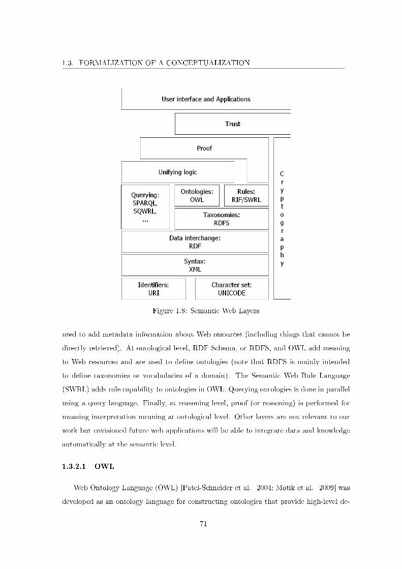
1.3. FORMALIZATION OF A CONCEPTUALIZATION
Figure 1.8: Semantic Web Layers
used to add metadata information about Web resources (including things that cannot be
directly retrieved). At ontological level, RDF Schema, or RDFS, and OWL add meaning
to Web resources and are used to de�ne ontologies (note that RDFS is mainly intended
to de�ne taxonomies or vocabularies of a domain). The Semantic Web Rule Language
(SWRL) adds rule capability to ontologies in OWL. Querying ontologies is done in parallel
using a query language. Finally, at reasoning level, proof (or reasoning) is performed for
meaning interpretation meaning at ontological level. Other layers are not relevant to our
work but envisioned future web applications will be able to integrate data and knowledge
automatically at the semantic level.
1.3.2.1 OWL
Web Ontology Language (OWL) [Patel-Schneider et al. 2004; Motik et al. 2009] was
developed as an ontology language for constructing ontologies that provide high-level de-
71
1.3. FORMALIZATION OF A CONCEPTUALIZATION
scriptions of Web content. As any ontology language, OWL enables to de�ne individuals,
classes, attributes and relations. Classes are organized into hierarchies and are related to
one another with properties (i.e., relations). OWL provides mechanisms for reasoning at
both class and individual levels and a powerful constraint language that enables to give
a precise interpretation for the concepts in an ontology. Compared to XML, RDF and
RDFS, OWL is more expressive and has greater machine interpretability [Stuckenschmidt
and Harmelen 2005]. OWL adds more vocabulary for describing classes, instances and
properties. Among others, relations between classes (e.g., disjointness), properties cardi-
nality (e.g., exactly one), instances equality, richer typing of properties, properties charac-
teristics (e.g., transitivity), and enumerated classes. In the end OWL is used to explicitly
represent the meaning of terms in vocabularies and the relationships between those terms.
For example, with RDFS we can de�ne classes like Actuator and Command with a prop-
erty sendsCommand that has Command as its domain and Actuator as its range. With
OWL, we can additionally de�ne that Actuator and Command are disjoint classes, that
receivesCommand is the inverse property of sendsCommand, and that Actuator is de�ned
precisely as the individuals of Actuator that have at least one value with the property
receivesCommand.
In terms of reasoning capabilities, our interest mainly lies in the veri�cation of con-
sistency under the OWA assumption. One characteristic of the World Wide Web is that
information is incomplete. Assuming we de�ned an individual of Actuator, "EMB" for
instance (EMB stands for Electro-Mechanical Brake), checking consistency will not result
in CWA contradiction: the EMB is an actuator and it should receive a command which
is not the case. But rather, OWA answer will be EMB is an actuator, it should receive
a command which is unknown (not de�ned) at the moment. Understanding information
with OWA seemed more precise and was retained as a characteristic of an ontology lan-
guage to use. Reasoning with OWL is therefore oriented towards deducing knew knowledge
from the de�nitions of the ontology. However, OWL provides limited deductive reasoning
capabilities and relatively recent work has concentrated on adding rules to it.
72
1.3. FORMALIZATION OF A CONCEPTUALIZATION
1.3.2.2 SWRL
The Semantic Web Rule Language (SWRL) [Horrocks et al. 2004] complements OWL
for the de�nition of an ontology. Similarly with many rule languages, SWRL rules are
written as couples (antecedent,consequent). The antecedent is referred to as the rule body
and the consequent is referred to as the head. The head and body consist of a conjunction
of one or more atoms. SWRL rules reason about OWL individuals, primarily in terms of
OWL classes and properties. It provides deductive reasoning capabilities that can infer
new knowledge from an OWL ontology. For example, with OWL we de�ne the property
interpretsCommand and three individuals "Brake request", "Acceleration Request" and
"EMB" (all distinct). The �rst two individuals belong to Command and the last one
belongs to Actuator. Also "EMB" can only interpret "Brake request" and we set receives-
Command between the EMB and the two commands. With SWRL we can capture that
an actuator tries to interpret a command when it receives one. The rule in SWRL would
be: Actuator(?x)∧receivesCommand(?x, ?y)→ interprets_Command(?x, ?y). The rule
body is the conjunction on the left of the arrow and the head is the conjunction on the
right. Executing the rule will try to match any individuals in the body (thus the ?) and
set the property interpretsCommand for matching individuals. This interesting property
already demonstrates two important aspects of rules. In terms of reasoning capabilities,
SWRL does enable to deduce additional knowledge from an OWL ontology. However,
unlike axioms, the truth value of the head should be questioned. As we de�ned that the
EMB receives all the commands, the rule wants to conclude that it also interprets these
commands. But we de�ned that the only command the EMB can interpret is the brake
request. Therefore, inconsistent knowledge can be deduced from rules which should be
treated with precaution. SWRL also provides numerous built-ins (that are user-de�ned
methods) that can be extended. Implemented built-ins enable more expressiveness and
address XML data-types. For instance, integer comparison operators are de�ned and enable
to retrieve all the actuators with a weight greater than 5 kg as a general example. In the
end, OWL and SWRL can be used in combination in the semantic web to de�ne an ontology.
73
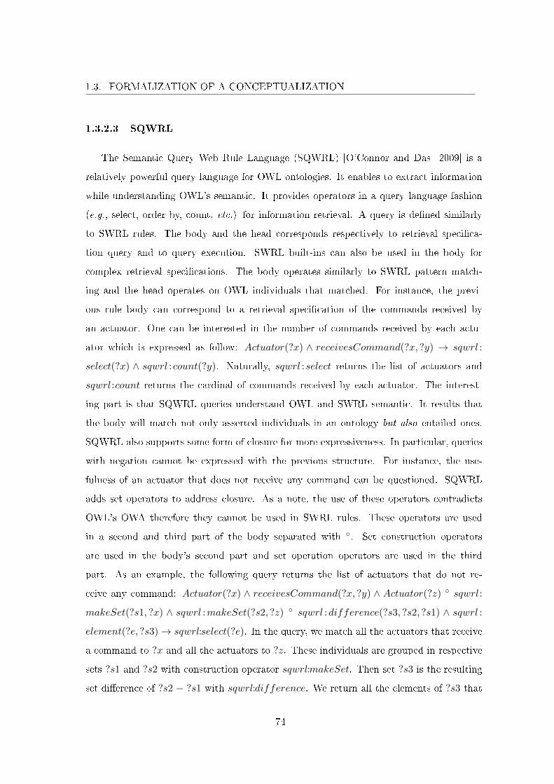
1.3. FORMALIZATION OF A CONCEPTUALIZATION
1.3.2.3 SQWRL
The Semantic Query Web Rule Language (SQWRL) [O'Connor and Das 2009] is a
relatively powerful query language for OWL ontologies. It enables to extract information
while understanding OWL's semantic. It provides operators in a query language fashion
(e.g., select, order by, count, etc.) for information retrieval. A query is de�ned similarly
to SWRL rules. The body and the head corresponds respectively to retrieval speci�ca-
tion query and to query execution. SWRL built-ins can also be used in the body for
complex retrieval speci�cations. The body operates similarly to SWRL pattern match-
ing and the head operates on OWL individuals that matched. For instance, the previ-
ous rule body can correspond to a retrieval speci�cation of the commands received by
an actuator. One can be interested in the number of commands received by each actu-
ator which is expressed as follow: Actuator(?x) ∧ receivesCommand(?x, ?y) → sqwrl :
select(?x) ∧ sqwrl :count(?y). Naturally, sqwrl :select returns the list of actuators and
sqwrl :count returns the cardinal of commands received by each actuator. The interest-
ing part is that SQWRL queries understand OWL and SWRL semantic. It results that
the body will match not only asserted individuals in an ontology but also entailed ones.
SQWRL also supports some form of closure for more expressiveness. In particular, queries
with negation cannot be expressed with the previous structure. For instance, the use-
fulness of an actuator that does not receive any command can be questioned. SQWRL
adds set operators to address closure. As a note, the use of these operators contradicts
OWL's OWA therefore they cannot be used in SWRL rules. These operators are used
in a second and third part of the body separated with ◦. Set construction operators
are used in the body's second part and set operation operators are used in the third
part. As an example, the following query returns the list of actuators that do not re-
ceive any command: Actuator(?x) ∧ receivesCommand(?x, ?y) ∧ Actuator(?z) ◦ sqwrl:
makeSet(?s1, ?x) ∧ sqwrl :makeSet(?s2, ?z) ◦ sqwrl :difference(?s3, ?s2, ?s1) ∧ sqwrl :
element(?e, ?s3)→ sqwrl:select(?e). In the query, we match all the actuators that receive
a command to ?x and all the actuators to ?z. These individuals are grouped in respective
sets ?s1 and ?s2 with construction operator sqwrl:makeSet. Then set ?s3 is the resulting
set di�erence of ?s2 − ?s1 with sqwrl:difference. We return all the elements of ?s3 that
74
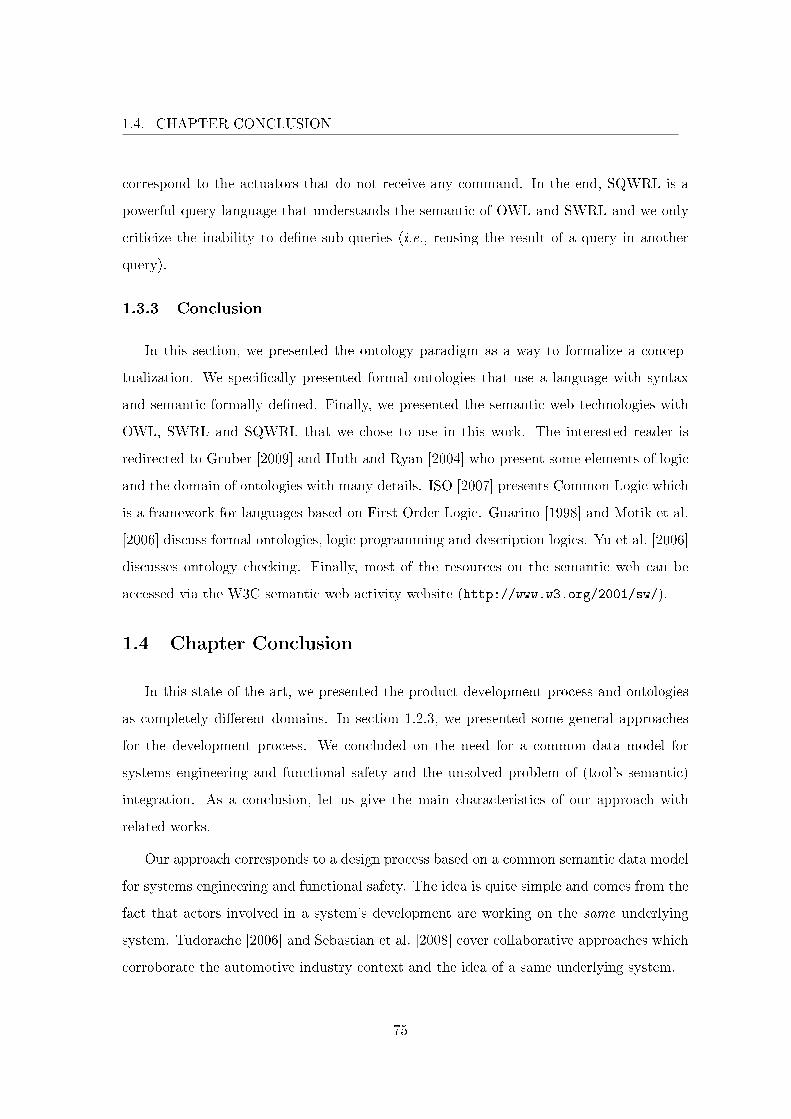
1.4. CHAPTER CONCLUSION
correspond to the actuators that do not receive any command. In the end, SQWRL is a
powerful query language that understands the semantic of OWL and SWRL and we only
criticize the inability to de�ne sub-queries (i.e., reusing the result of a query in another
query).
1.3.3 Conclusion
In this section, we presented the ontology paradigm as a way to formalize a concep-
tualization. We speci�cally presented formal ontologies that use a language with syntax
and semantic formally de�ned. Finally, we presented the semantic web technologies with
OWL, SWRL and SQWRL that we chose to use in this work. The interested reader is
redirected to Gruber [2009] and Huth and Ryan [2004] who present some elements of logic
and the domain of ontologies with many details. ISO [2007] presents Common Logic which
is a framework for languages based on First Order Logic. Guarino [1998] and Motik et al.
[2006] discuss formal ontologies, logic programming and description logics. Yu et al. [2006]
discusses ontology checking. Finally, most of the resources on the semantic web can be
accessed via the W3C semantic web activity website (http://www.w3.org/2001/sw/).
1.4 Chapter Conclusion
In this state of the art, we presented the product development process and ontologies
as completely di�erent domains. In section 1.2.3, we presented some general approaches
for the development process. We concluded on the need for a common data model for
systems engineering and functional safety and the unsolved problem of (tool's semantic)
integration. As a conclusion, let us give the main characteristics of our approach with
related works.
Our approach corresponds to a design process based on a common semantic data model
for systems engineering and functional safety. The idea is quite simple and comes from the
fact that actors involved in a system's development are working on the same underlying
system. Tudorache [2006] and Sebastian et al. [2008] cover collaborative approaches which
corroborate the automotive industry context and the idea of a same underlying system.
75
1.4. CHAPTER CONCLUSION
In our approach, the reference data model is realized with a formal ontology. Compared
to other approaches, the data model's semantic is formally de�ned. Burr et al. [2005],
Suwanmanee et al. [2005] and Driouche et al. [2007] discuss data integration in the design
process. Data integration enables the exchange of information between applications and
thus interoperability. It is shown that the real interoperability problem is to address
semantic interoperability between heterogeneous tool's conceptualizations. For example,
when two di�erent tools communicate, their communication is based on the assumption
that they understand one another, i.e., similar concepts have the same meaning in each
tool. The use of a formal ontology (and its formal semantics) simply transforms this
assumption into a property. Previous integration solutions mostly address only syntactic
integration which is actually still the case. For instance, in the case of Model Driven
Engineering, Harmelen and Fensel [1995]; Evans et al. [1998]; Brucker et al. [2006]; Micskei
and Waeselynck [2010] demonstrate that UML /SysML, even with OCL, have no formal
semantics. It results that using MDE technologies such as the popular Eclipse platform with
EMOF (Eclipse Meta Object Facility), can make the tools inter-operate. But these tools
are not integrated at the semantic level. This may lead to error prone misunderstandings.
Ontologies and the semantic web technologies have been actively used to deal with the
semantic interoperability problem [Sure et al. 2002; Bussler 2003; Stuckenschmidt and
Harmelen 2005; Suwanmanee et al. 2005; Driouche et al. 2007]. In our approach, we
build upon these ideas and go further by exploiting the semantic web during the design
process, in order to ensure its consistency.
In this thesis, we do not propose a fundamentally new approach. As explained, related
works have already identi�ed the problem of semantic integration. We pursue the idea that,
by analogy to Model Driven Engineering, it is possible to solve semantic integration in the
design process by doing "Ontology Driven Engineering". It is relatively new and to our
knowledge has only been partially presented by Gasevic et al. [2009]. We use the semantic
web technologies to propose a design approach based on a common underlying ontology
that enables to verify information consistency all along the design process. The next
chapter presents our contributions: the production of a systems engineering and functional
safety ontology that formalizes and integrates the domains presented in sections 1.2.1 and
76

1.4. CHAPTER CONCLUSION
1.2.2; the ontology centric design approach which is compliant to ISO 26262 standard and
enables to guarantee information consistency at the semantic level.
77
Chapter 2
Contribution
Sommaire
2.1 Introduction . . . . . . . . . . . . . . . . . . . . . . . . . . . . . . 80
2.2 Domains Formalization . . . . . . . . . . . . . . . . . . . . . . . . 81
2.2.1 Systems Engineering Ontology . . . . . . . . . . . . . . . . . . . 83
2.2.1.1 On Needs . . . . . . . . . . . . . . . . . . . . . . . . . . 84
2.2.1.2 On Requirements . . . . . . . . . . . . . . . . . . . . . 86
2.2.1.3 On Functional Architecture . . . . . . . . . . . . . . . . 99
2.2.1.4 On Physical Architecture . . . . . . . . . . . . . . . . . 103
2.2.1.5 On Traceability . . . . . . . . . . . . . . . . . . . . . . 108
2.2.1.6 On Non Functional Requirements . . . . . . . . . . . . 126
2.2.1.7 Conclusion . . . . . . . . . . . . . . . . . . . . . . . . . 132
2.2.2 Functional Safety Ontology . . . . . . . . . . . . . . . . . . . . . 133
2.2.2.1 Risk Analysis . . . . . . . . . . . . . . . . . . . . . . . . 134
2.2.2.2 Risk Evaluation and Safety Concept . . . . . . . . . . . 143
2.2.2.3 Conclusion . . . . . . . . . . . . . . . . . . . . . . . . . 153
2.2.3 Conclusion . . . . . . . . . . . . . . . . . . . . . . . . . . . . . . 154
2.3 Global Domain Formalization . . . . . . . . . . . . . . . . . . . . 155
2.3.1 Systems Engineering and Functional Safety Domains Integration 156
2.3.1.1 Conceptual Integration . . . . . . . . . . . . . . . . . . 156
2.3.1.2 On Individuals Integration . . . . . . . . . . . . . . . . 161
2.3.1.3 Conclusion . . . . . . . . . . . . . . . . . . . . . . . . . 164
2.3.2 Ontology Based ASIL Propagation . . . . . . . . . . . . . . . . . 164
2.3.2.1 Systems Elements Traceability Establishment. . . . . . 165
2.3.2.2 ASIL Propagation. . . . . . . . . . . . . . . . . . . . . . 168
2.3.2.3 Conclusion . . . . . . . . . . . . . . . . . . . . . . . . . 175
2.3.3 Conclusion . . . . . . . . . . . . . . . . . . . . . . . . . . . . . . 175
2.4 Ontology Centric Design Approach for Safety Critical Auto-
motive Mechatronics Systems . . . . . . . . . . . . . . . . . . . . 176
2.4.1 Place of the Ontology in the Design Process . . . . . . . . . . . . 177
78
2.4.1.1 Use of the Reference Model . . . . . . . . . . . . . . . . 178
2.4.1.2 On Model Transformation . . . . . . . . . . . . . . . . . 181
2.4.1.3 Conclusion . . . . . . . . . . . . . . . . . . . . . . . . . 185
2.4.2 Ontology Centric Design Process . . . . . . . . . . . . . . . . . . 186
2.4.2.1 Understanding Design Process Knowledge . . . . . . . . 188
2.4.2.2 Need Analysis and Stakeholders Requirements De�nition 189
2.4.2.3 System Level Requirements De�nition . . . . . . . . . . 191
2.4.2.4 Functional and Physical Architecture De�nition . . . . 194
2.4.2.5 Conclusion . . . . . . . . . . . . . . . . . . . . . . . . . 195
2.4.3 Conclusion . . . . . . . . . . . . . . . . . . . . . . . . . . . . . . 196
2.5 Chapter Conclusion . . . . . . . . . . . . . . . . . . . . . . . . . . 196
79
2.1. INTRODUCTION
2.1 Introduction
Problems of the Current Design Process
The model-based design approaches outlined in section 1.2.3 call for di�erent design
objects that have to be described as clearly as possible (e.g., requirements, system archi-
tectures, safety goals, system use-cases, Feared Customer and System Events, fault trees,
etc.). The �rst implementations of the process at Renault were mainly document-centric
and depended largely on testing and simulation [Chalé Góngora et al. 2009]. Although
these �rst attempts gave quite satisfactory results in building safe system architectures,
the creation of the di�erent objects of the process was somewhat troublesome and rela-
tively time-consuming. The reason for this is that the objects were modeled by means of
transformations of ad-hoc data and information contained in the di�erent documents that
were transmitted from one process step to the other.
The main di�culty in implementing the process consisted thus in the lack of semantic
consistency among the di�erent modeled objects. This need for a better formalization is
further stressed by the fact that car manufacturers rely heavily on third parties to develop
vehicle systems. A better formalization of processes and process objects would certainly
contribute to avoid confusion and misinterpretations in the development of systems. All
this led us to the conclusion that the use of formal and informal (but consistent) models can
commit to a common semantic model, i.e., a system and safety ontology, which purpose
is to better understand all the aspects of safety-critical system design.
Content of the Chapter
This chapter presents the contributions. Based on identi�ed issues of the current design
process at Renault, we propose an approach that addresses those problems that can be
generalized and applied by any company. In particular for Renault, the domains of systems
engineering and of functional safety are the main point of focus. As such, the chapter is
structured in order to cover two signi�cant contributions of the thesis. The �rst is the
realization of a domain ontology for Renault systems and safety engineers. The second is
the improvement of the design process with the domain ontology as a basis.
80
2.2. DOMAINS FORMALIZATION
Section 2.2 presents the formalization of the conceptualization of systems engineering
and functional safety domains. Section 2.3 is the integration of the systems engineering
and functional safety ontology into a domain ontology that supports the design process for
systems and safety engineers. The domain ontology de�nes the sharing of a conceptualiza-
tion that promotes synergies. Section 2.4 presents our approach: Ontology Based Design
Process. Finally, section 2.5 gives some conclusions.
2.2 Domains Formalization
Formalization of knowledge addresses the problematic of harnessing and reusing knowl-
edge, a key point for all domains. In the engineering domain, decision making is funda-
mental as engineers are confronted with multiple choices and only one solution will be
subject to complete development. In order to choose the best solution, the engineers need
the relevant necessary knowledge required to perform informed decision making. Currently,
content created in the development process is ultimately archived and forgotten, knowledge
is lost whereas archived. There is evident need to make use of this produced and archived
knowledge considering the probable occurrence of confrontation with an already solved
problem. There is two important points to verify in order to address this issue. First, some
quality of knowledge needs to be assessed. For that aspect we want to verify the consis-
tency of knowledge. Second, for easy reuse of knowledge, conceptualization of knowledge
needs to be shared as reusing something that is not understood can be detrimental. The
formalization activity consists in better structuring knowledge, enabling computer treat-
ment for more performing information retrieval that has to bring relevant information to
the surface. This can be implemented in an elegant fashion using the ontology paradigm.
This work focuses on two speci�c engineering �elds of Renault Research and Advanced
Engineering. The �rst domain is systems engineering. With systems being more and more
complex at Renault, the need for system engineers and system thinking is becoming press-
ing matter. Systems engineering is a relatively new domain at Renault and deployment is
in progress. Similarly, the second domain, functional safety, is subject to change required
for conformity with ISO 26262 international standard. Sections 2.2.1 and 2.2.2 respec-
81
2.2. DOMAINS FORMALIZATION
tively present the formalization of systems engineering and functional safety domains with
ontologies that tackles previous issues in knowledge quality.
Even though the formalization (via ontologies) has been done using OWL and SWRL
(see section 1.3), in this chapter, the formalization is presented using First Order Logic
(FOL). The reader is assumed to be familiar with FOL. Using it enables to reason under
usual closed world assumption, to express negative facts and to use logical disjunction (⊕)
which makes reading more natural. All these languages are formal in the sense that their
syntaxes and semantics are de�ned formally which enables veri�cations such as consistency.
The formalization of systems engineering and functional safety is done following the par-
tial axiomatization given in appendix A. Informally, the axiomatization de�nes instance,
class and property. Instances are expressed with constant symbols. Variables are used only
to refer to sets of instances. For example, the instance constant can be substituted to the
variable x. A class formalizes a concept as a set of instances. A class is expressed with a
unary predicate whose term is a concatenation of words with their �rst letter capitalized
(e.g., the class Requirement). Requirement(x) denotes the set of instances that can be
substituted to x that are in the set Requirement. A property formalizes a role from one
instance to another. A property is expressed by a binary predicate whose term is a concate-
nation of terms. The �rst word is a verb in lowercase conjugated at the third singular person
and the following words have their �rst letter capitalized. That corresponds to the relation
name . It is followed by an underscore and another term and can be followed by another
underscore and term, e.g., hasPart_DomCoDom and hasConstituant_Dom_CoDom.
In the case of only one underscore, the term after the underscore refers to the domain and
the co-domain of an internal relation expressing a class attribute. Otherwise, the term after
the �rst underscore refers to the relation domain relation and the term after the second
underscore refers to the relation co-domain expressing a role from a domain instance to
a co-domain one. For example, hasPart_DomCoDom(x, y) denotes the set of couples of
instances that are a substitution of x and y with x, y ∈ DomCodom. It expresses a whole
to part relation, so the user should understand the substitution of x being the whole and
the substitution of y being the part. The terms class and concept, property and relation,
instance and individual, and, range and co-domain, are used indi�erently pairwise. All the
82
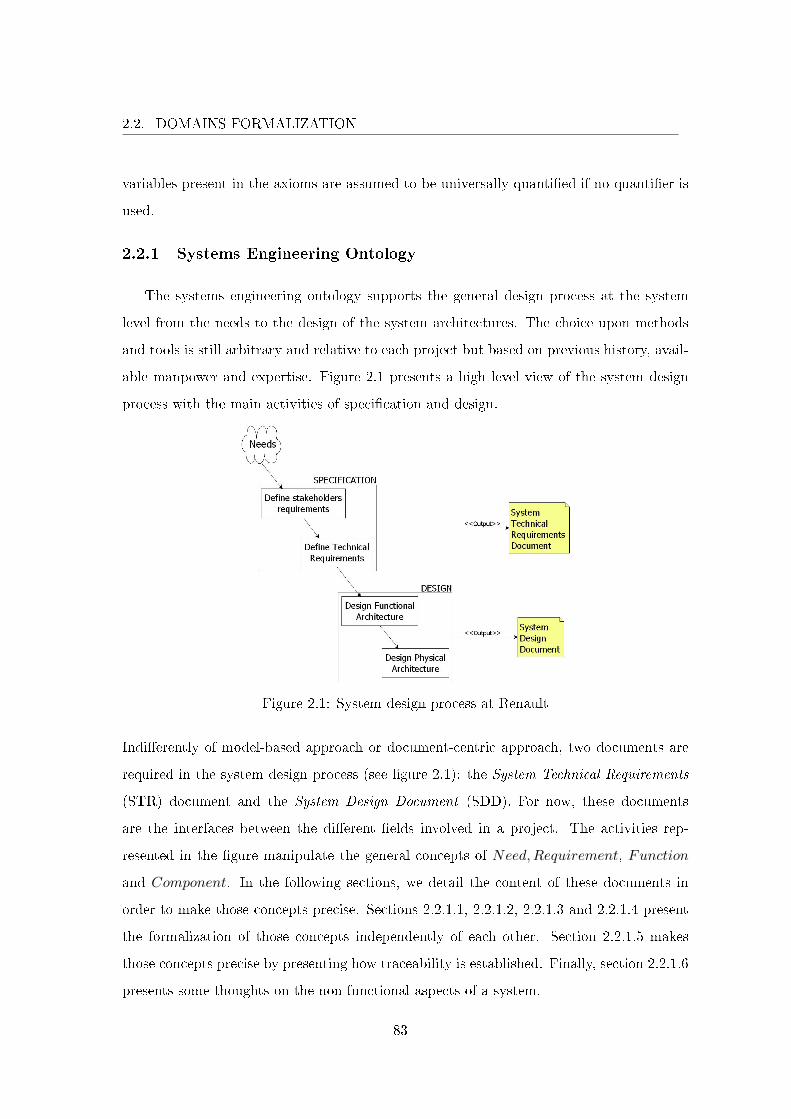
2.2. DOMAINS FORMALIZATION
variables present in the axioms are assumed to be universally quanti�ed if no quanti�er is
used.
2.2.1 Systems Engineering Ontology
The systems engineering ontology supports the general design process at the system
level from the needs to the design of the system architectures. The choice upon methods
and tools is still arbitrary and relative to each project but based on previous history, avail-
able manpower and expertise. Figure 2.1 presents a high level view of the system design
process with the main activities of speci�cation and design.
Figure 2.1: System design process at Renault
Indi�erently of model-based approach or document-centric approach, two documents are
required in the system design process (see �gure 2.1): the System Technical Requirements
(STR) document and the System Design Document (SDD). For now, these documents
are the interfaces between the di�erent �elds involved in a project. The activities rep-
resented in the �gure manipulate the general concepts of Need,Requirement, Function
and Component. In the following sections, we detail the content of these documents in
order to make those concepts precise. Sections 2.2.1.1, 2.2.1.2, 2.2.1.3 and 2.2.1.4 present
the formalization of those concepts independently of each other. Section 2.2.1.5 makes
those concepts precise by presenting how traceability is established. Finally, section 2.2.1.6
presents some thoughts on the non functional aspects of a system.
83
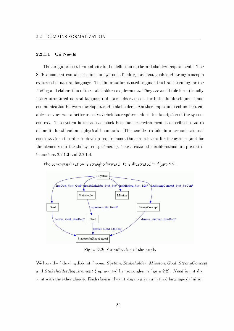
2.2. DOMAINS FORMALIZATION
2.2.1.1 On Needs
The design process �rst activity is the de�nition of the stakeholders requirements. The
STR document contains sections on system's �nality, missions, goals and strong concepts
expressed in natural language. This information is used to guide the brainstorming for the
�nding and elaboration of the stakeholders requirements. They are a suitable form (usually
better structured natural language) of stakeholders needs, for both the development and
communication between developers and stakeholders. Another important section that en-
ables to construct a better set of stakeholders requirements is the description of the system
context. The system is taken as a black box and its environment is described so as to
de�ne its functional and physical boundaries. This enables to take into account external
considerations in order to develop requirements that are relevant for the system (and for
the elements outside the system perimeter). These external considerations are presented
in sections 2.2.1.3 and 2.2.1.4.
The conceptualization is straight-forward. It is illustrated in �gure 2.2.
Figure 2.2: Formalization of the needs
We have the following disjoint classes: System, Stakeholder,Mission, Goal, StrongConcept,
and StakeholderRequirement (represented by rectangles in �gure 2.2). Need is not dis-
joint with the other classes. Each class in the ontology is given a natural language de�nition
84
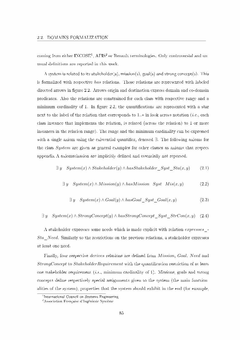
2.2. DOMAINS FORMALIZATION
coming from either INCOSE1, AFIS2 or Renault terminologies. Only controversial and un-
usual de�nitions are reported in this work.
A system is related to its stakeholder(s), mission(s), goal(s) and strong concept(s). This
is formalized with respective has relations. Those relations are represented with labeled
directed arrows in �gure 2.2. Arrows origin and destination express domain and co-domain
predicates. Also the relations are constrained for each class with respective range and a
minimum cardinality of 1. In �gure 2.2, the quanti�cations are represented with a star
next to the label of the relation that corresponds to 1..∗ in look across notation (i.e., each
class instance that implements the relation, is related (across the relation) to 1 or more
instances in the relation range). The range and the minimum cardinality can be expressed
with a single axiom using the existential quanti�er, denoted ∃. The following axioms for
the class System are given as general examples for other classes as axioms that respect
appendix A axiomatization are implicitly de�ned and essentially not reported.
∃ y System(x) ∧ Stakeholder(y) ∧ hasStakeholder_Syst_Sta(x, y) (2.1)
∃ y System(x) ∧Mission(y) ∧ hasMission_Syst_Mis(x, y) (2.2)
∃ y System(x) ∧Goal(y) ∧ hasGoal_Syst_Goal(x, y) (2.3)
∃ y System(x) ∧ StrongConcept(y) ∧ hasStrongConcept_Syst_StrCon(x, y) (2.4)
A stakeholder expresses some needs which is made explicit with relation expresses_-
Sta_Need. Similarly to the restrictions on the previous relations, a stakeholder expresses
at least one need.
Finally, four respective derives relations are de�ned from Mission, Goal, Need and
StrongConcept to StakeholderRequirement with the quanti�cation restriction of at least
one stakeholder requirement (i.e., minimum cardinality of 1). Missions, goals and strong
concepts de�ne respectively special assignments given to the system (the main function-
alities of the system), properties that the system should exhibit in the end (for example,
1International Council on Systems Engineering2Association Française d'Ingénierie Système
85
2.2. DOMAINS FORMALIZATION
a usual goal of a new braking system is for its price to be at most the same as an earlier
braking system) and unavoidable concepts that constrain the solutions for the system in an
unavoidable manner (such as using or not using speci�c technologies. For instance using
electro-mechanical brake actuators on the front wheels of the vehicle is a strong concept
for the braking system used in the case study). Each of the classes, Need, Mission, Goal
and StrongConcept, account for the domain of need. They have to be taken into account
by the system development which is done by making them more accurate as stakeholders
requirements using respective derives properties.
Even though those classes can be better structured with other relations, we did not go
further on the formalization of the needs (yet some precisions are given in section 3.3.2)
as our interest was on the integration of functional safety to systems engineering which we
start at the abstraction level of requirements.
2.2.1.2 On Requirements
Stakeholders needs are the entry point into the somewhat more formal world of require-
ments. The requirement concept is �rst de�ned as a general concept with coverage greater
than what is contained in the STR document. Then, based on this general de�nition, the
concept is made precise.
The Concept of Requirement As a general de�nition, a requirement is a statement
that expresses a need and/or a constraint. As stated in section 1.2.1.1, requirements are
still an active subject of research. They delimit the frontier between the informal and the
more formal worlds in the development process. The di�culty is relative to the high degree
of ambiguity of the informal world. No attempt is given to formalize the statement that
constitutes the requirement. The presented conceptualization makes precise a typology of
requirements and their relations with other concepts. From the universe of discourse, we
only retain that a requirement can:
• be decomposed into other requirements;
• derive other types of requirements;
86

2.2. DOMAINS FORMALIZATION
• relate to other requirements to detail a peculiar aspect of the former requirement;
• relate to functions or �ows that implement the requirement;
• be allocated to a system, a function, a component or a �ow.
Figure 2.3 illustrates the requirement concept formalization at the most general level of
abstraction. As it can be seen in the �gure, the concepts Requirement, Function, Flow
Figure 2.3: Formalization of the requirement concept
and Component are de�ned along with the previous concepts of System, Stakeholder,
Need and StalkeholderRequirement. The rest of the formalization de�nes the relations
of requirements with other concepts through properties hasPart_Req for the decomposi-
tion of a requirement in a whole to part manner, derives_Req to relate di�erent kinds of
requirements, characterizes_Req and isCharacterizedBy_Req for the precision of a re-
quirement by another and the converse, deduces_Req_Func and deduces_Req_Flow to
relate a requirement to a function or a �ow identi�able in the requirement statement, and
four respective isAllocatedTo properties for the allocation of a requirement to a system,
a function, a component or a �ow. There is no cardinality constraints on the properties
(the stars in �gure 2.3 next to the relations names correspond to 0..∗, i.e., a class instance
at the origin of an arrow is related to 0 or more class instances at the arrow destination).
This is done intentionally for staying at the highest degree of abstraction by expressing the
possible relations that a requirement is involved with. Making the requirement concept
precise is actually removing this "possible" aspect of requirements descriptions.
87
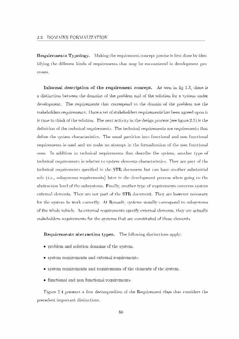
2.2. DOMAINS FORMALIZATION
Requirements Typology. Making the requirement concept precise is �rst done by iden-
tifying the di�erent kinds of requirements that may be encountered in development pro-
cesses.
Informal description of the requirement concept. As seen in �g 1.3, there is
a distinction between the domains of the problem and of the solution for a system under
development. The requirements that correspond to the domain of the problem are the
stakeholders requirements. Once a set of stakeholders requirements has been agreed upon it
is time to think of the solution. The next activity in the design process (see �gure 2.1) is the
de�nition of the technical requirements. The technical requirements are requirements that
de�ne the system characteristics. The usual partition into functional and non functional
requirements is used and we make no attempt in the formalization of the non functional
ones. In addition to technical requirements that describe the system, another type of
technical requirements is relative to system elements characteristics. They are part of the
technical requirements speci�ed in the STR document but can have another substantial
role (i.e., subsystems requirements) later in the development process when going to the
abstraction level of the subsystems. Finally, another type of requirements concerns system
external elements. They are not part of the STR document. They are however necessary
for the system to work correctly. At Renault, systems usually correspond to subsystems
of the whole vehicle. As external requirements specify external elements, they are actually
stakeholders requirements for the systems that are constituted of these elements.
Requirements abstraction types. The following distinctions apply:
• problem and solution domains of the system.
• system requirements and external requirements.
• system requirements and requirements of the elements of the system.
• functional and non functional requirements.
Figure 2.4 presents a �rst decomposition of the Requirement class that considers the
precedent important distinctions.
88
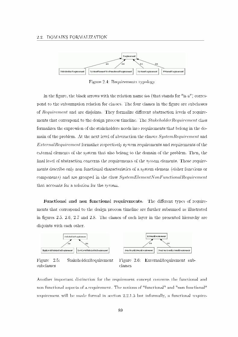
2.2. DOMAINS FORMALIZATION
Figure 2.4: Requirements typology
In the �gure, the black arrows with the relation name isa (that stands for "is a") corres-
pond to the subsumption relation for classes. The four classes in the �gure are subclasses
of Requirement and are disjoints. They formalize di�erent abstraction levels of require-
ments that correspond to the design process timeline. The StakeholderRequirement class
formalizes the expression of the stakeholders needs into requirements that belong in the do-
main of the problem. At the next level of abstraction the classes SystemRequirement and
ExternalRequirement formalize respectively system requirements and requirements of the
external elements of the system that also belong to the domain of the problem. Then, the
�nal level of abstraction concerns the requirements of the system elements. Those require-
ments describe only non functional characteristics of a system element (either functions or
components) and are grouped in the class SystemElementNonFunctionalRequirement
that accounts for a solution for the system.
Functional and non functional requirements. The di�erent types of require-
ments that correspond to the design process timeline are further subsumed as illustrated
in �gures 2.5, 2.6, 2.7 and 2.8. The classes of each layer in the presented hierarchy are
disjoints with each other.
Figure 2.5: StakeholderRequirementsubclasses
Figure 2.6: ExternalRequirement sub-classes
Another important distinction for the requirement concept concerns the functional and
non functional aspects of a requirement. The notions of "functional" and "non functional"
requirement will be made formal in section 2.2.1.5 but informally, a functional require-
89
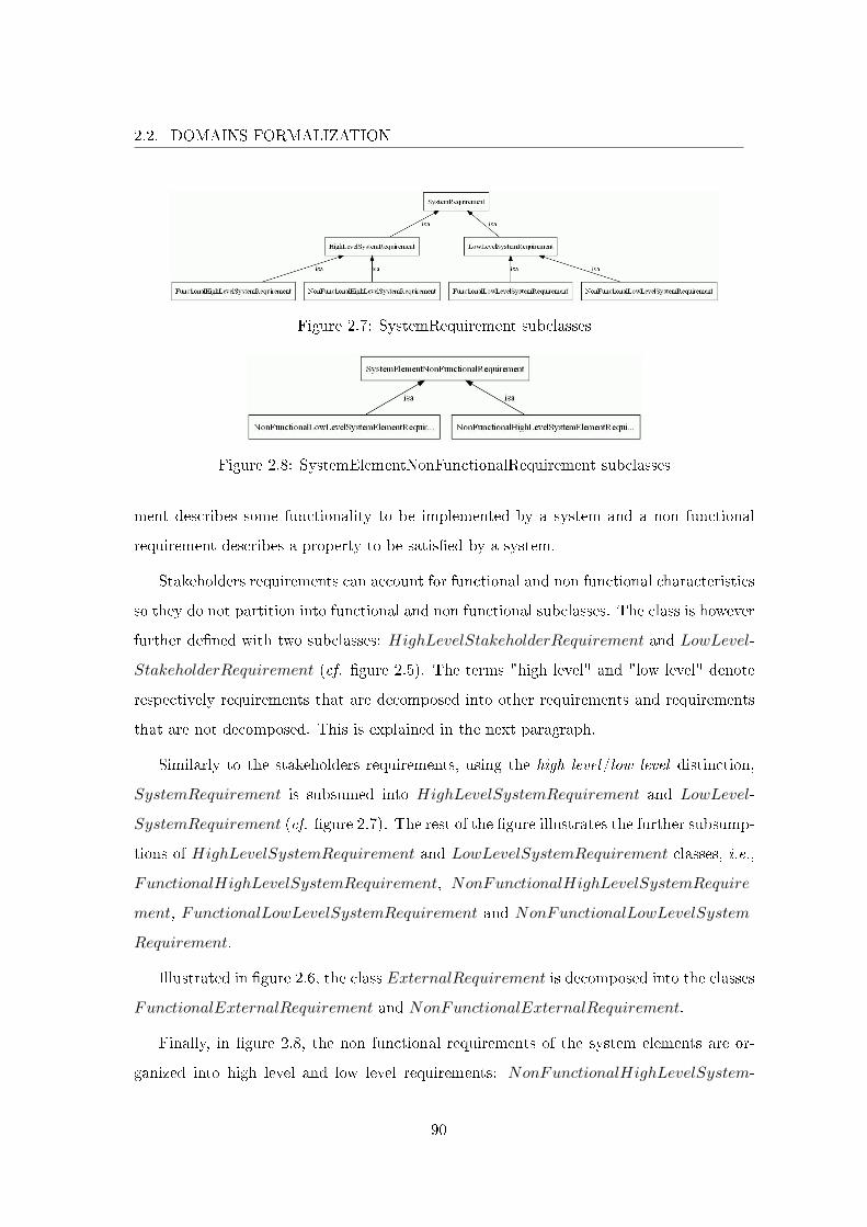
2.2. DOMAINS FORMALIZATION
Figure 2.7: SystemRequirement subclasses
Figure 2.8: SystemElementNonFunctionalRequirement subclasses
ment describes some functionality to be implemented by a system and a non functional
requirement describes a property to be satis�ed by a system.
Stakeholders requirements can account for functional and non functional characteristics
so they do not partition into functional and non functional subclasses. The class is however
further de�ned with two subclasses: HighLevelStakeholderRequirement and LowLevel-
StakeholderRequirement (cf. �gure 2.5). The terms "high level" and "low level" denote
respectively requirements that are decomposed into other requirements and requirements
that are not decomposed. This is explained in the next paragraph.
Similarly to the stakeholders requirements, using the high level/low level distinction,
SystemRequirement is subsumed into HighLevelSystemRequirement and LowLevel-
SystemRequirement (cf. �gure 2.7). The rest of the �gure illustrates the further subsump-
tions of HighLevelSystemRequirement and LowLevelSystemRequirement classes, i.e.,
FunctionalHighLevelSystemRequirement, NonFunctionalHighLevelSystemRequire-
ment, FunctionalLowLevelSystemRequirement and NonFunctionalLowLevelSystem-
Requirement.
Illustrated in �gure 2.6, the class ExternalRequirement is decomposed into the classes
FunctionalExternalRequirement and NonFunctionalExternalRequirement.
Finally, in �gure 2.8, the non functional requirements of the system elements are or-
ganized into high level and low level requirements: NonFunctionalHighLevelSystem-
90

2.2. DOMAINS FORMALIZATION
ElementRequirement and NonFunctionalLowLevelSystemElementRequirement.
We do not go further on the di�erent kinds of requirements. There is indeed a con-
sequent number of di�erent non functional requirements. Formalizing a relevant subset
of the di�erent types of non functional requirements that relates to critical mechatronic
systems for the automotive domain has been quickly set aside. It has nonetheless been
examined. Although it has not been formalized, it is set up partially in a formal manner
in the ontology with explicit intentions that are presented in section 2.2.1.6.
Requirements Decomposition. The requirements are usually structured in a hierar-
chical manner, i.e., a requirement can be decomposed into sub-requirements. As a sub-
requirement has no conceptual addition to the Requirement class, it is not de�ned as a
class. The Requirement class is simply structured in relation to itself by de�ning the
hasPart_Req property with the Requirement as domain and range. This property is
intended to express the invers relational quality of parthood as to follow the top-down
development. Using hasPart_Req(x, y) states that "x is a super-requirement of y" and
"y is a sub-requirement of x". There is no cardinality constraints on the hasPart_Req
property (stars in �gure 2.3 next to relations names correspond to 0..∗) therefore the rela-
tion of decomposition of a requirement describes both the possible sub-requirements and
super-requirements of a requirement. In other words, a requirement can be in relation with
0, 1 or more sub-requirements and 0, 1 or more super-requirements. This is illustrated in
�gure 2.9 with squares representing requirements instances and the arrows representing
the hasPart property.
Figure 2.9: Possible constructions for the hasPart property
Complying with the axiomatization given in appendix A, the hasPart property is inherited
91
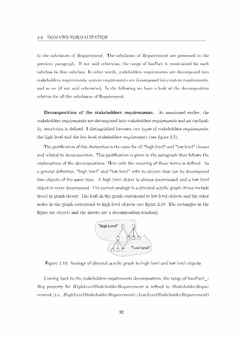
2.2. DOMAINS FORMALIZATION
to the subclasses of Requirement. The subclasses of Requirement are presented in the
previous paragraph. If not said otherwise, the range of hasPart is constrained for each
subclass to that subclass. In other words, stakeholders requirements are decomposed into
stakeholders requirements, system requirements are decomposed into system requirements,
and so on (if not said otherwise). In the following we have a look at the decomposition
relation for all the subclasses of Requirement.
Decomposition of the stakeholders requirements. As mentioned earlier, the
stakeholders requirements are decomposed into stakeholders requirements and no cardinal-
ity restriction is de�ned. I distinguished between two types of stakeholders requirements:
the high level and the low level stakeholders requirements (see �gure 2.5).
The justi�cation of this distinction is the same for all "high level" and "low level" classes
and related to decomposition. This justi�cation is given in the paragraph that follows the
explanations of the decompositions. Here only the meaning of those terms is de�ned. As
a general de�nition, "high level" and "low level" refer to objects that can be decomposed
into objects of the same type. A high level object is always decomposed and a low level
object is never decomposed. The correct analogy is a directed acyclic graph (those include
trees) in graph theory. The leafs in the graph correspond to low level objects and the other
nodes in the graph correspond to high level objects (see �gure 2.10. The rectangles in the
�gure are objects and the arrows are a decomposition relation).
Figure 2.10: Analogy of directed acyclic graph to high level and low level objects
Coming back to the stakeholders requirements decomposition, the range of hasPart_-
Req property for HighLevelStakeholderRequirement is re�ned to StakeholderRequi-
rement (i.e., HighLevelStakeholderRequirement∪LowLevelStakeholderRequirement)
92
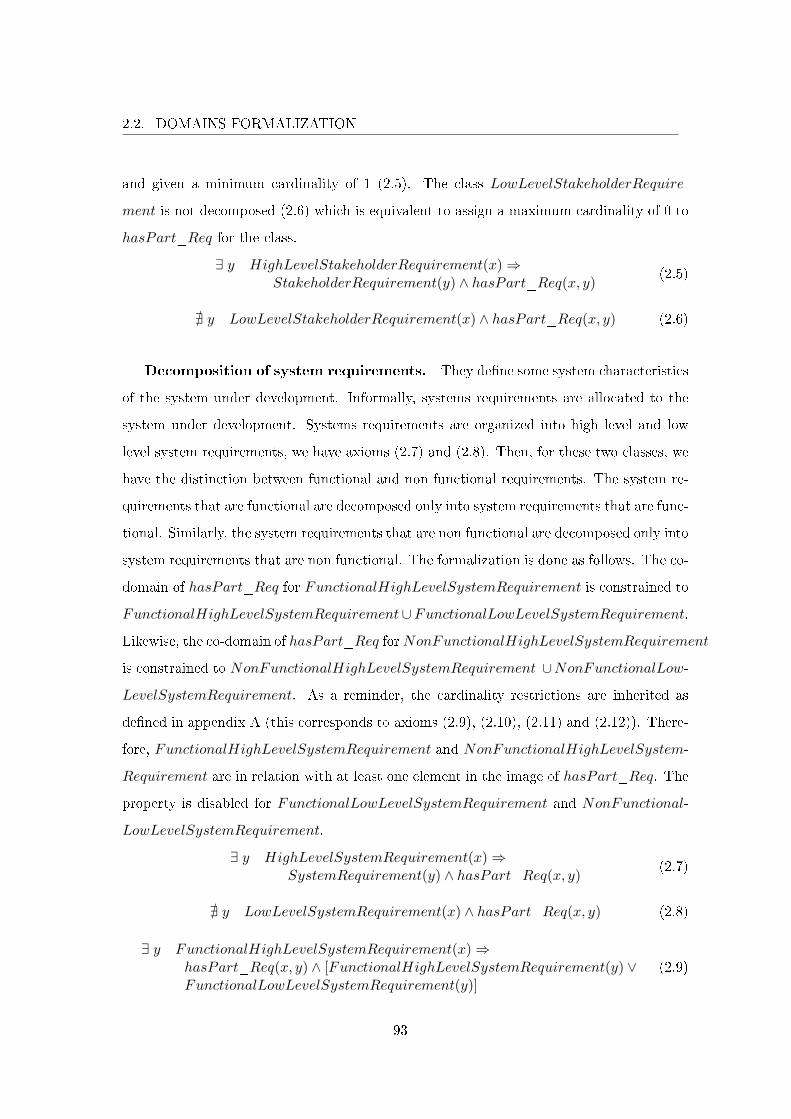
2.2. DOMAINS FORMALIZATION
and given a minimum cardinality of 1 (2.5). The class LowLevelStakeholderRequire-
ment is not decomposed (2.6) which is equivalent to assign a maximum cardinality of 0 to
hasPart_Req for the class.
∃ y HighLevelStakeholderRequirement(x)⇒StakeholderRequirement(y) ∧ hasPart_Req(x, y)
(2.5)
@ y LowLevelStakeholderRequirement(x) ∧ hasPart_Req(x, y) (2.6)
Decomposition of system requirements. They de�ne some system characteristics
of the system under development. Informally, systems requirements are allocated to the
system under development. Systems requirements are organized into high level and low
level system requirements, we have axioms (2.7) and (2.8). Then, for these two classes, we
have the distinction between functional and non functional requirements. The system re-
quirements that are functional are decomposed only into system requirements that are func-
tional. Similarly, the system requirements that are non functional are decomposed only into
system requirements that are non functional. The formalization is done as follows. The co-
domain of hasPart_Req for FunctionalHighLevelSystemRequirement is constrained to
FunctionalHighLevelSystemRequirement∪FunctionalLowLevelSystemRequirement.
Likewise, the co-domain of hasPart_Req forNonFunctionalHighLevelSystemRequirement
is constrained to NonFunctionalHighLevelSystemRequirement ∪NonFunctionalLow-
LevelSystemRequirement. As a reminder, the cardinality restrictions are inherited as
de�ned in appendix A (this corresponds to axioms (2.9), (2.10), (2.11) and (2.12)). There-
fore, FunctionalHighLevelSystemRequirement and NonFunctionalHighLevelSystem-
Requirement are in relation with at least one element in the image of hasPart_Req. The
property is disabled for FunctionalLowLevelSystemRequirement and NonFunctional-
LowLevelSystemRequirement.
∃ y HighLevelSystemRequirement(x)⇒SystemRequirement(y) ∧ hasPart_Req(x, y)
(2.7)
@ y LowLevelSystemRequirement(x) ∧ hasPart_Req(x, y) (2.8)
∃ y FunctionalHighLevelSystemRequirement(x)⇒hasPart_Req(x, y) ∧ [FunctionalHighLevelSystemRequirement(y) ∨FunctionalLowLevelSystemRequirement(y)]
(2.9)
93
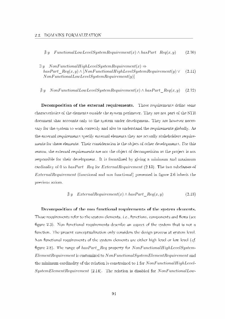
2.2. DOMAINS FORMALIZATION
@ y FunctionalLowLevelSystemRequirement(x) ∧ hasPart_Req(x, y) (2.10)
∃ y NonFunctionalHighLevelSystemRequirement(x)⇒hasPart_Req(x, y) ∧ [NonFunctionalHighLevelSystemRequirement(y) ∨NonFunctionalLowLevelSystemRequirement(y)]
(2.11)
@ y NonFunctionalLowLevelSystemRequirement(x) ∧ hasPart_Req(x, y) (2.12)
Decomposition of the external requirements. Those requirements de�ne some
characteristics of the elements outside the system perimeter. They are not part of the STR
document that accounts only to the system under development. They are however neces-
sary for the system to work correctly and also to understand the requirements globally. As
the external requirements specify external elements they are actually stakeholders require-
ments for these elements. Their consideration is the object of other developments. For this
reason, the external requirements are not the object of decomposition as the project is not
responsible for their development. It is formalized by giving a minimum and maximum
cardinality of 0 to hasPart_Req for ExternalRequirement (2.13). The two subclasses of
ExternalRequirement (functional and non functional) presented in �gure 2.6 inherit the
previous axiom.
@ y ExternalRequirement(x) ∧ hasPart_Req(x, y) (2.13)
Decomposition of the non functional requirements of the system elements.
Those requirements refer to the system elements, i.e., functions, components and �ows (see
�gure 2.3). Non functional requirements describe an aspect of the system that is not a
function. The present conceptualization only considers the design process at system level.
Non functional requirements of the system elements are either high level or low level (cf.
�gure 2.8). The range of hasPart_Req property for NonFunctionalHighLevelSystem-
ElementRequirement is customized toNonFunctionalSystemElementRequirement and
the minimum cardinality of the relation is constrained to 1 for NonFunctionalHighLevel-
SystemElementRequirement (2.14). The relation is disabled for NonFunctionalLow-
94
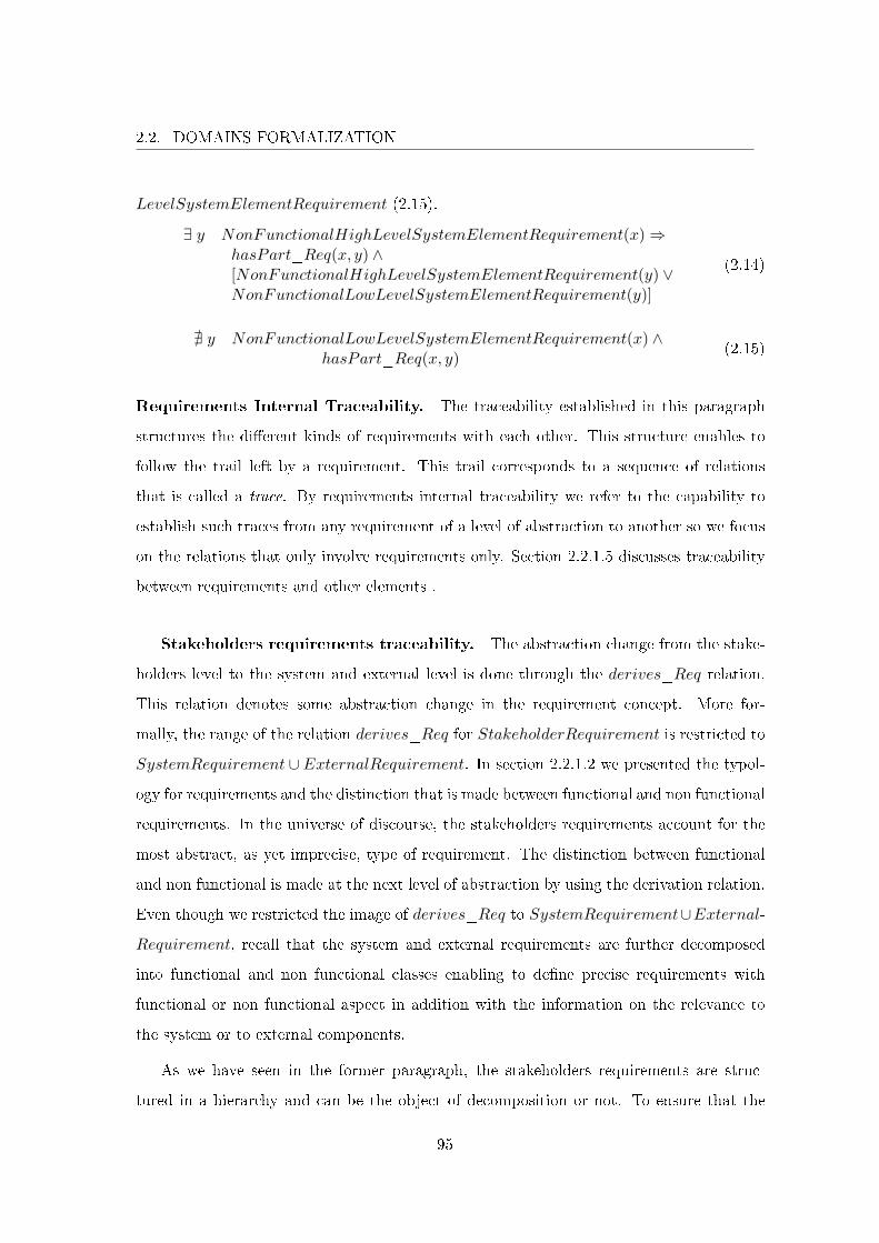
2.2. DOMAINS FORMALIZATION
LevelSystemElementRequirement (2.15).
∃ y NonFunctionalHighLevelSystemElementRequirement(x)⇒hasPart_Req(x, y) ∧[NonFunctionalHighLevelSystemElementRequirement(y) ∨NonFunctionalLowLevelSystemElementRequirement(y)]
(2.14)
@ y NonFunctionalLowLevelSystemElementRequirement(x) ∧hasPart_Req(x, y)
(2.15)
Requirements Internal Traceability. The traceability established in this paragraph
structures the di�erent kinds of requirements with each other. This structure enables to
follow the trail left by a requirement. This trail corresponds to a sequence of relations
that is called a trace. By requirements internal traceability we refer to the capability to
establish such traces from any requirement of a level of abstraction to another so we focus
on the relations that only involve requirements only. Section 2.2.1.5 discusses traceability
between requirements and other elements .
Stakeholders requirements traceability. The abstraction change from the stake-
holders level to the system and external level is done through the derives_Req relation.
This relation denotes some abstraction change in the requirement concept. More for-
mally, the range of the relation derives_Req for StakeholderRequirement is restricted to
SystemRequirement ∪ ExternalRequirement. In section 2.2.1.2 we presented the typol-
ogy for requirements and the distinction that is made between functional and non functional
requirements. In the universe of discourse, the stakeholders requirements account for the
most abstract, as yet imprecise, type of requirement. The distinction between functional
and non functional is made at the next level of abstraction by using the derivation relation.
Even though we restricted the image of derives_Req to SystemRequirement∪External-
Requirement, recall that the system and external requirements are further decomposed
into functional and non functional classes enabling to de�ne precise requirements with
functional or non functional aspect in addition with the information on the relevance to
the system or to external components.
As we have seen in the former paragraph, the stakeholders requirements are struc-
tured in a hierarchy and can be the object of decomposition or not. To ensure that the
95
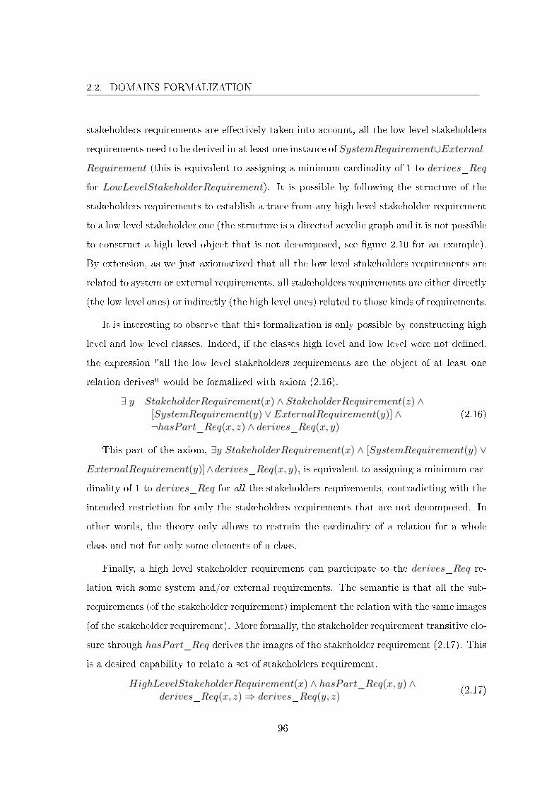
2.2. DOMAINS FORMALIZATION
stakeholders requirements are e�ectively taken into account, all the low level stakeholders
requirements need to be derived in at least one instance of SystemRequirement∪External-
Requirement (this is equivalent to assigning a minimum cardinality of 1 to derives_Req
for LowLevelStakeholderRequirement). It is possible by following the structure of the
stakeholders requirements to establish a trace from any high level stakeholder requirement
to a low level stakeholder one (the structure is a directed acyclic graph and it is not possible
to construct a high level object that is not decomposed, see �gure 2.10 for an example).
By extension, as we just axiomatized that all the low level stakeholders requirements are
related to system or external requirements, all stakeholders requirements are either directly
(the low level ones) or indirectly (the high level ones) related to those kinds of requirements.
It is interesting to observe that this formalization is only possible by constructing high
level and low level classes. Indeed, if the classes high level and low level were not de�ned,
the expression "all the low level stakeholders requirements are the object of at least one
relation derives" would be formalized with axiom (2.16).
∃ y StakeholderRequirement(x) ∧ StakeholderRequirement(z) ∧[SystemRequirement(y) ∨ ExternalRequirement(y)] ∧¬hasPart_Req(x, z) ∧ derives_Req(x, y)
(2.16)
This part of the axiom, ∃y StakeholderRequirement(x) ∧ [SystemRequirement(y) ∨
ExternalRequirement(y)]∧derives_Req(x, y), is equivalent to assigning a minimum car-
dinality of 1 to derives_Req for all the stakeholders requirements, contradicting with the
intended restriction for only the stakeholders requirements that are not decomposed. In
other words, the theory only allows to restrain the cardinality of a relation for a whole
class and not for only some elements of a class.
Finally, a high level stakeholder requirement can participate to the derives_Req re-
lation with some system and/or external requirements. The semantic is that all the sub-
requirements (of the stakeholder requirement) implement the relation with the same images
(of the stakeholder requirement). More formally, the stakeholder requirement transitive clo-
sure through hasPart_Req derives the images of the stakeholder requirement (2.17). This
is a desired capability to relate a set of stakeholders requirement.
HighLevelStakeholderRequirement(x) ∧ hasPart_Req(x, y) ∧derives_Req(x, z)⇒ derives_Req(y, z)
(2.17)
96
2.2. DOMAINS FORMALIZATION
Functional system requirements traceability. Functional system requirements
(i.e., FunctionalHighLevelSystemRequirement and FunctionalLowLevelSystemRequi-
rement) are detailed through the decomposition relation (with requirements whose state-
ments are more precise and more atomic) and by other requirements that account for non
functional characteristics that supplement the functional statement of the functional re-
quirement. For instance, the requirement "The braking system shall decelerate the vehicle"
is functional. The requirement "The braking system shall decelerate the vehicle and shall
allow a deceleration ≥ 5.8m.s− 2" amounts for an additional non functional characteristic
to the decelerate function. It is non functional.
A functional system requirement can also be related to some external requirements. A rela-
tion with functional or non functional external requirements exhibit some stakes (functional
or non functional) for the proper functioning of the system that are emergent properties
at a greater level of abstraction than the system under development. For example, if the
system commands another system, the system is responsible for sending commands to the
other system that is responsible for receiving and handling the commands. If the other
system does not receive or handle the command, the functionality (at the level of abstrac-
tion that comprises both the system and the external system) is lost. Similarly, if the other
system handles the command too slowly, the functioning property is also lost.
The abstraction change from functional system requirements to non functional sys-
tem requirements is formalized with the property isCharacterizedBy_Req. The co-
domain of isCharacterizedBy_Req is restricted to NonFunctionalHighLevelSystem-
Requirement∪NonFunctionalLowLevelSystemRequirement for FunctionalHighLevel-
SystemRequirement and FunctionalLowLevelSystemRequirement. A minimum cardi-
nality of 1 is given to isCharacterizedBy_Req for FunctionalLowLevelSystemRequi-
rement. By construction, all the functional system requirements are related directly or
indirectly (through the decomposition relation) to at least one non functional system re-
quirement, ensuring that non functional aspects of a functional requirement are taken into
account in the design. Axiom (2.18) is the capability to characterize a set of functional
97
2.2. DOMAINS FORMALIZATION
system requirements.
FunctionalHighLevelSystemRequirement(x) ∧ hasPart_Req(x, y) ∧isCharacterizedBy_Req(x, z)⇒ isCharacterizedBy_Req(y, z)
(2.18)
Relation derives_Req is used once again between functional system requirements and
functional external requirements. The range of the relation is constrained to Functional-
HighLevelSystemRequirement ∪ FunctionalLowLevelSystemRequirement.
Finally, the relation derivesNonFuncExtReq_FuncSystReq_NonFuncExtReq is added
with FunctionalHighLevelSystemRequirement∪FunctionalLowLevelSystemRequirement
as domain and NonFunctionalExternalRequirement as co-domain. It enables to express
some non functional stakes on the external elements of the system from the functional
system requirements if needed. Therefore the relation cardinality is not constrained.
Functional external requirements traceability. First, remember that the exter-
nal requirements can be related directly with the stakeholders requirements (and now they
can be related to functional system requirements). Therefore, it exists some functional ex-
ternal requirements that are not the object of the derives_Req relation for the functional
system requirements. It is important however to ensure that all the functional external re-
quirements are related to some functional system requirement (this will be explained in sec-
tion 2.3.2). This is realized by de�ning the relation isDerivedFrom_FuncExtReq_Func-
SystReq with FunctionalExternalRequirement as domain and FunctionalHighLevel-
SystemRequirement∪FunctionalLowLevelSystemRequirement as co-domain. Functional-
ExternalRequirement implements the relation and the image of isDerivedFrom_FuncExtReq_-
FuncSystReq is de�ned for the class to FunctionalHighLevelSystemRequirement ∪
FunctionalLowLevelSystemRequirement and given a minimum cardinality of 1. As the
external requirements are not decomposed those axioms are su�cient to ensure that all the
functional external requirements are related to at least one functional system requirement.
Non functional system requirements traceability. The derives_Req property
is used one last time to relate non functional system requirements to non functional require-
ments of the system elements. The relation range is customized to NonFunctionalHigh-
LevelSystemElementRequirement∪NonFunctionalLowLevelSystemElementRequirement
98
2.2. DOMAINS FORMALIZATION
forNonFunctionalHighLevelSystemRequirement andNonFunctionalLowLevelSystem-
Requirement. The relation is given a minimum cardinality of 1 for NonFunctionalLow-
LevelSystemRequirement to ensure that all the non functional system requirements are
related directly or indirectly (through hasPart_Req) to at least one non functional re-
quirement of a system element. It is once again given the possibility to relate a set of
non functional system requirements to a non functional requirement of a system element
through derives_Req as de�ned by axiom (2.19).
NonFunctionalHighLevelSystemRequirement(x) ∧ hasPart_Req(x, y) ∧isCharacterizedBy_Req(x, z)⇒ isCharacterizedBy_Req(y, z)
(2.19)
2.2.1.3 On Functional Architecture
In the previous STR document, the system has been considered as a black box to iden-
tify the necessary interactions with the environment. The level of detail vary from lists of
external functions and elements to system context diagrams. As mentioned, this de�nition
of the system context accounts for the system interactions with its environment. The en-
vironment has been described but not detailed. In this section, we detail the de�nition of
the system functional architecture, see �gure 2.1. We are interested only in the functional
aspect of the environment and in the whitening of the functional aspect of the previous
black box system that has to interact with the environment.
As an introduction, the SDD contains a duplicate of the description of the system
missions and context. Then the system architecture is presented. The functional architec-
ture describes the functions or transformations that the system must perform. The �ows
(i.e., information, energy or material �ows) that are relevant to the functions are speci�ed
as well. The system internal behavior is also described and corresponds to the logical
execution of the system functions.
We used the most common representation for functional architectures as a basis for
the formalization. The functional architecture description is usually done with a kind
of block diagram. The notation makes use of two basic elements, blocks and arrows.
Blocks represent respective functions and arrows represent respective �ows. An Arrow
origin designates the function that produces the �ow. Similarly, an arrow destination
99
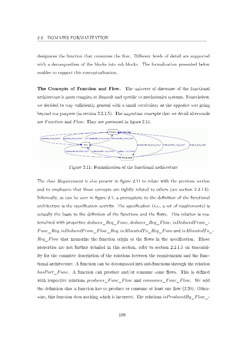
2.2. DOMAINS FORMALIZATION
designates the function that consumes the �ow. Di�erent levels of detail are supported
with a decomposition of the blocks into sub-blocks. The formalization presented below
enables to support this conceptualization.
The Concepts of Function and Flow. The universe of discourse of the functional
architecture is more complex at Renault and speci�c to mechatonics systems. Nonetheless,
we decided to stay su�ciently general with a small vocabulary as the opposite was going
beyond our purpose (in section 2.2.1.5). The important concepts that we detail afterwards
are Function and Flow. They are presented in �gure 2.11.
Figure 2.11: Formalization of the functional architecture
The class Requirement is also present in �gure 2.11 to relate with the previous section
and to emphasize that those concepts are tightly related to others (see section 2.2.1.5).
Informally, as can be seen in �gure 2.1, a prerequisite to the de�nition of the functional
architecture is the speci�cation activity. The speci�cation (i.e., a set of requirements) is
actually the basis to the de�nition of the functions and the �ows. This relation is ma-
terialized with properties deduces_Req_Func, deduces_Req_Flow, isDeducedFrom_-
Func_Req, isDeducedFrom_Flow_Req, isAllocatedTo_Req_Func and isAllocatedTo_-
Req_Flow that memorize the function origin or the �ows in the speci�cation. Those
properties are not further detailed in this section, refer to section 2.2.1.5 on traceabil-
ity for the complete description of the relations between the requirements and the func-
tional architecture. A function can be decomposed into sub-functions through the relation
hasPart_Func. A function can produce and/or consume some �ows. This is de�ned
with respective relations produces_Func_Flow and consumes_Func_Flow. We add
the de�nition that a function has to produce or consume at least one �ow (2.20). Other-
wise, this function does nothing which is incorrect. The relations isProducedBy_Flow_-
100
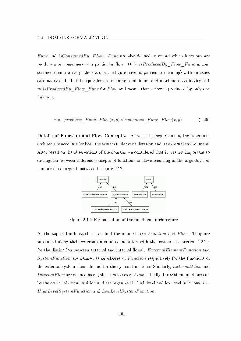
2.2. DOMAINS FORMALIZATION
Func and isConsumedBy_FLow_Func are also de�ned to record which functions are
producers or consumers of a particular �ow. Only isProducedBy_Flow_Func is con-
strained quantitatively (the stars in the �gure have no particular meaning) with an exact
cardinality of 1. This is equivalent to de�ning a minimum and maximum cardinality of 1
to isProducedBy_Flow_Func for Flow and means that a �ow is produced by only one
function.
∃ y produces_Func_Flow(x, y) ∨ consumes_Func_Flow(x, y) (2.20)
Details of Function and Flow Concepts. As with the requirements, the functional
architecture accounts for both the system under consideration and its external environment.
Also, based on the observations of the domain, we considered that it was not important to
distinguish between di�erent concepts of functions or �ows resulting in the arguably low
number of concepts illustrated in �gure 2.12.
Figure 2.12: Formalization of the functional architecture
At the top of the hierarchies, we �nd the main classes Function and Flow. They are
subsumed along their external/internal connotation with the system (see section 2.2.1.4
for the distinction between external and internal �ows). ExternalElementFunction and
SystemFunction are de�ned as subclasses of Function respectively for the functions of
the external system elements and for the system functions. Similarly, ExternalF low and
InternalF low are de�ned as disjoint subclasses of Flow. Finally, the system functions can
be the object of decomposition and are organized in high level and low level functions, i.e.,
HighLevelSystemFunction and LowLevelSystemFunction.
101
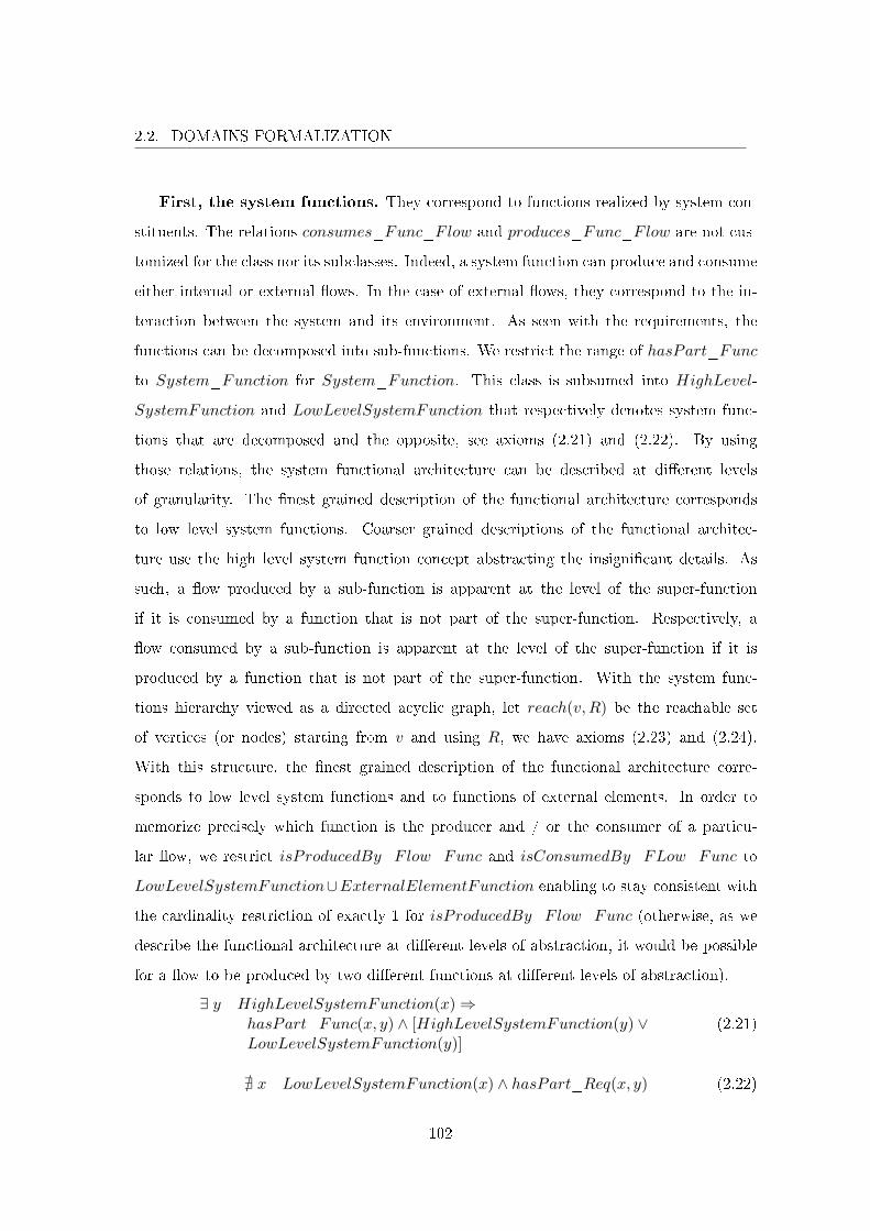
2.2. DOMAINS FORMALIZATION
First, the system functions. They correspond to functions realized by system con-
stituents. The relations consumes_Func_Flow and produces_Func_Flow are not cus-
tomized for the class nor its subclasses. Indeed, a system function can produce and consume
either internal or external �ows. In the case of external �ows, they correspond to the in-
teraction between the system and its environment. As seen with the requirements, the
functions can be decomposed into sub-functions. We restrict the range of hasPart_Func
to System_Function for System_Function. This class is subsumed into HighLevel-
SystemFunction and LowLevelSystemFunction that respectively denotes system func-
tions that are decomposed and the opposite, see axioms (2.21) and (2.22). By using
those relations, the system functional architecture can be described at di�erent levels
of granularity. The �nest grained description of the functional architecture corresponds
to low level system functions. Coarser grained descriptions of the functional architec-
ture use the high level system function concept abstracting the insigni�cant details. As
such, a �ow produced by a sub-function is apparent at the level of the super-function
if it is consumed by a function that is not part of the super-function. Respectively, a
�ow consumed by a sub-function is apparent at the level of the super-function if it is
produced by a function that is not part of the super-function. With the system func-
tions hierarchy viewed as a directed acyclic graph, let reach(v,R) be the reachable set
of vertices (or nodes) starting from v and using R, we have axioms (2.23) and (2.24).
With this structure, the �nest grained description of the functional architecture corre-
sponds to low level system functions and to functions of external elements. In order to
memorize precisely which function is the producer and / or the consumer of a particu-
lar �ow, we restrict isProducedBy_Flow_Func and isConsumedBy_FLow_Func to
LowLevelSystemFunction∪ExternalElementFunction enabling to stay consistent with
the cardinality restriction of exactly 1 for isProducedBy_Flow_Func (otherwise, as we
describe the functional architecture at di�erent levels of abstraction, it would be possible
for a �ow to be produced by two di�erent functions at di�erent levels of abstraction).
∃ y HighLevelSystemFunction(x)⇒hasPart_Func(x, y) ∧ [HighLevelSystemFunction(y) ∨LowLevelSystemFunction(y)]
(2.21)
@ x LowLevelSystemFunction(x) ∧ hasPart_Req(x, y) (2.22)
102
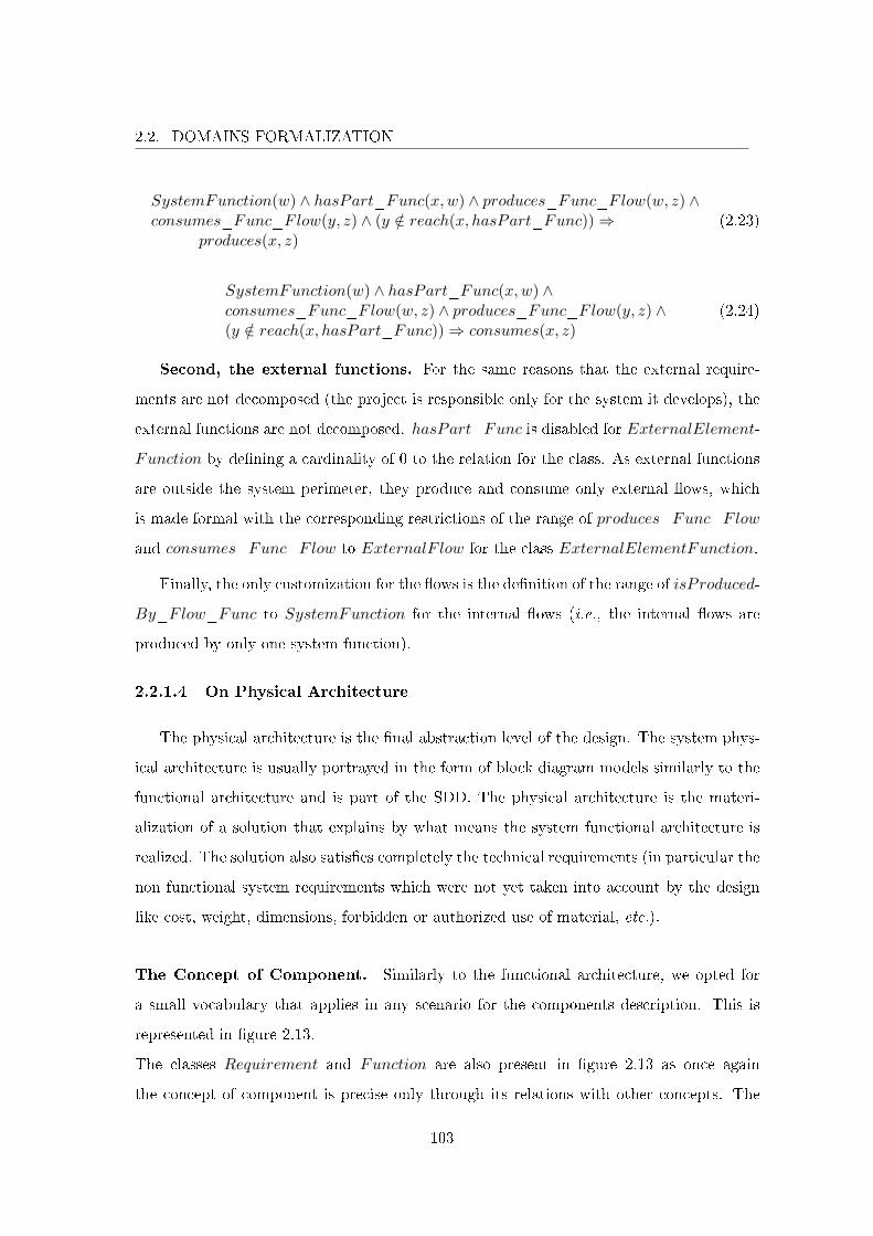
2.2. DOMAINS FORMALIZATION
SystemFunction(w) ∧ hasPart_Func(x,w) ∧ produces_Func_Flow(w, z) ∧consumes_Func_Flow(y, z) ∧ (y /∈ reach(x, hasPart_Func))⇒
produces(x, z)(2.23)
SystemFunction(w) ∧ hasPart_Func(x,w) ∧consumes_Func_Flow(w, z) ∧ produces_Func_Flow(y, z) ∧(y /∈ reach(x, hasPart_Func))⇒ consumes(x, z)
(2.24)
Second, the external functions. For the same reasons that the external require-
ments are not decomposed (the project is responsible only for the system it develops), the
external functions are not decomposed. hasPart_Func is disabled for ExternalElement-
Function by de�ning a cardinality of 0 to the relation for the class. As external functions
are outside the system perimeter, they produce and consume only external �ows, which
is made formal with the corresponding restrictions of the range of produces_Func_Flow
and consumes_Func_Flow to ExternalF low for the class ExternalElementFunction.
Finally, the only customization for the �ows is the de�nition of the range of isProduced-
By_Flow_Func to SystemFunction for the internal �ows (i.e., the internal �ows are
produced by only one system function).
2.2.1.4 On Physical Architecture
The physical architecture is the �nal abstraction level of the design. The system phys-
ical architecture is usually portrayed in the form of block diagram models similarly to the
functional architecture and is part of the SDD. The physical architecture is the materi-
alization of a solution that explains by what means the system functional architecture is
realized. The solution also satis�es completely the technical requirements (in particular the
non functional system requirements which were not yet taken into account by the design
like cost, weight, dimensions, forbidden or authorized use of material, etc.).
The Concept of Component. Similarly to the functional architecture, we opted for
a small vocabulary that applies in any scenario for the components description. This is
represented in �gure 2.13.
The classes Requirement and Function are also present in �gure 2.13 as once again
the concept of component is precise only through its relations with other concepts. The
103
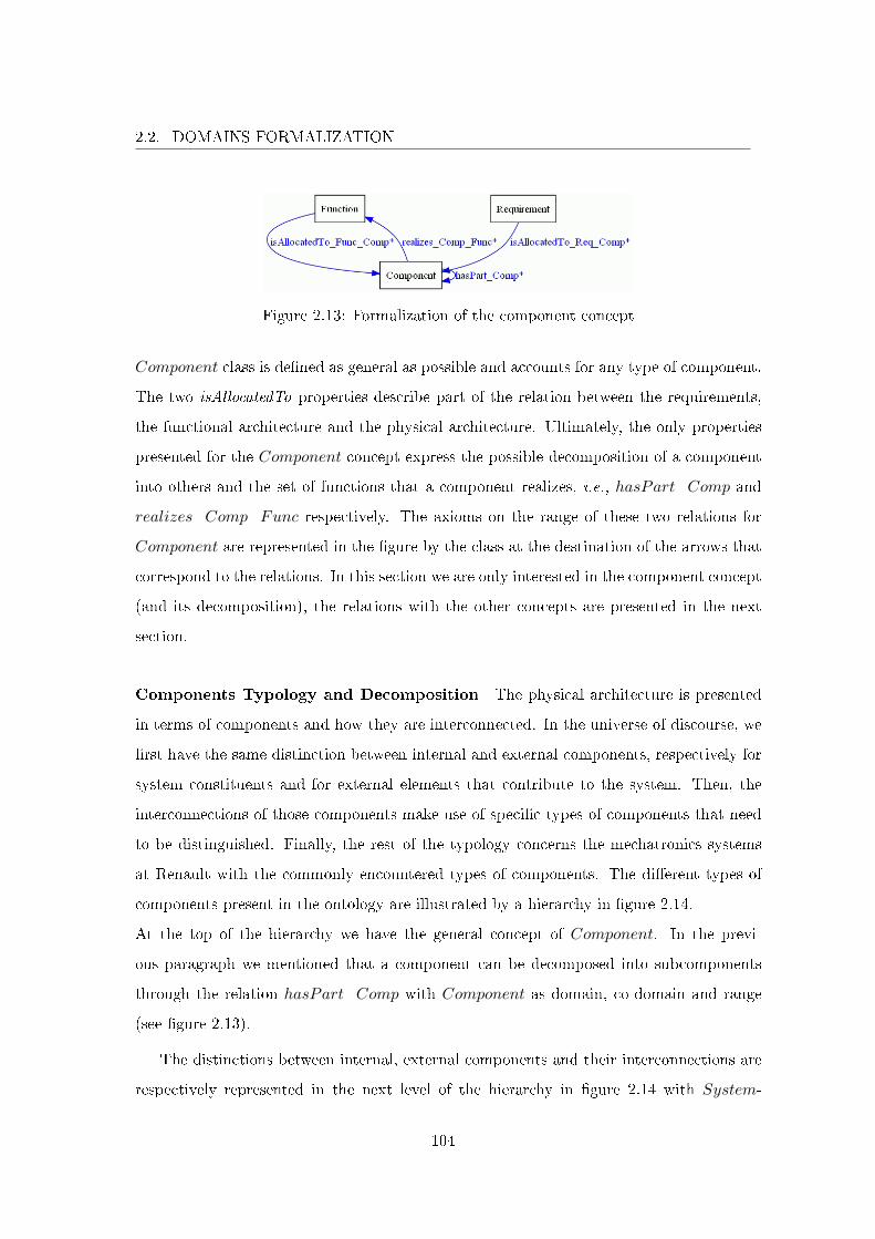
2.2. DOMAINS FORMALIZATION
Figure 2.13: Formalization of the component concept
Component class is de�ned as general as possible and accounts for any type of component.
The two isAllocatedTo properties describe part of the relation between the requirements,
the functional architecture and the physical architecture. Ultimately, the only properties
presented for the Component concept express the possible decomposition of a component
into others and the set of functions that a component realizes, i.e., hasPart_Comp and
realizes_Comp_Func respectively. The axioms on the range of these two relations for
Component are represented in the �gure by the class at the destination of the arrows that
correspond to the relations. In this section we are only interested in the component concept
(and its decomposition), the relations with the other concepts are presented in the next
section.
Components Typology and Decomposition The physical architecture is presented
in terms of components and how they are interconnected. In the universe of discourse, we
�rst have the same distinction between internal and external components, respectively for
system constituents and for external elements that contribute to the system. Then, the
interconnections of those components make use of speci�c types of components that need
to be distinguished. Finally, the rest of the typology concerns the mechatronics systems
at Renault with the commonly encountered types of components. The di�erent types of
components present in the ontology are illustrated by a hierarchy in �gure 2.14.
At the top of the hierarchy we have the general concept of Component. In the previ-
ous paragraph we mentioned that a component can be decomposed into subcomponents
through the relation hasPart_Comp with Component as domain, co-domain and range
(see �gure 2.13).
The distinctions between internal, external components and their interconnections are
respectively represented in the next level of the hierarchy in �gure 2.14 with System-
104
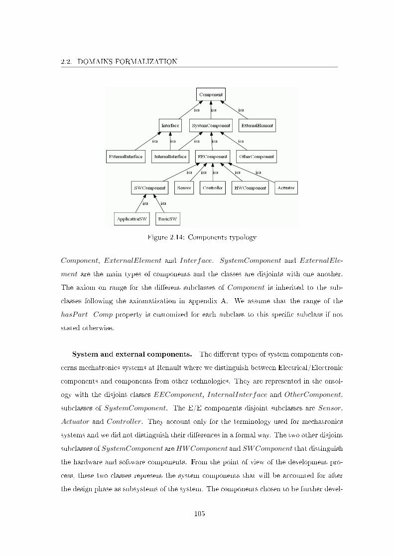
2.2. DOMAINS FORMALIZATION
Figure 2.14: Components typology
Component, ExternalElement and Interface. SystemComponent and ExternalEle-
ment are the main types of components and the classes are disjoints with one another.
The axiom on range for the di�erent subclasses of Component is inherited to the sub-
classes following the axiomatization in appendix A. We assume that the range of the
hasPart_Comp property is customized for each subclass to this speci�c subclass if not
stated otherwise.
System and external components. The di�erent types of system components con-
cerns mechatronics systems at Renault where we distinguish between Electrical/Electronic
components and components from other technologies. They are represented in the ontol-
ogy with the disjoint classes EEComponent, InternalInterface and OtherComponent,
subclasses of SystemComponent. The E/E components disjoint subclasses are Sensor,
Actuator and Controller. They account only for the terminology used for mechatronics
systems and we did not distinguish their di�erences in a formal way. The two other disjoint
subclasses of SystemComponent areHWComponent and SWComponent that distinguish
the hardware and software components. From the point of view of the development pro-
cess, these two classes represent the system components that will be accounted for after
the design phase as subsystems of the system. The components chosen to be further devel-
105
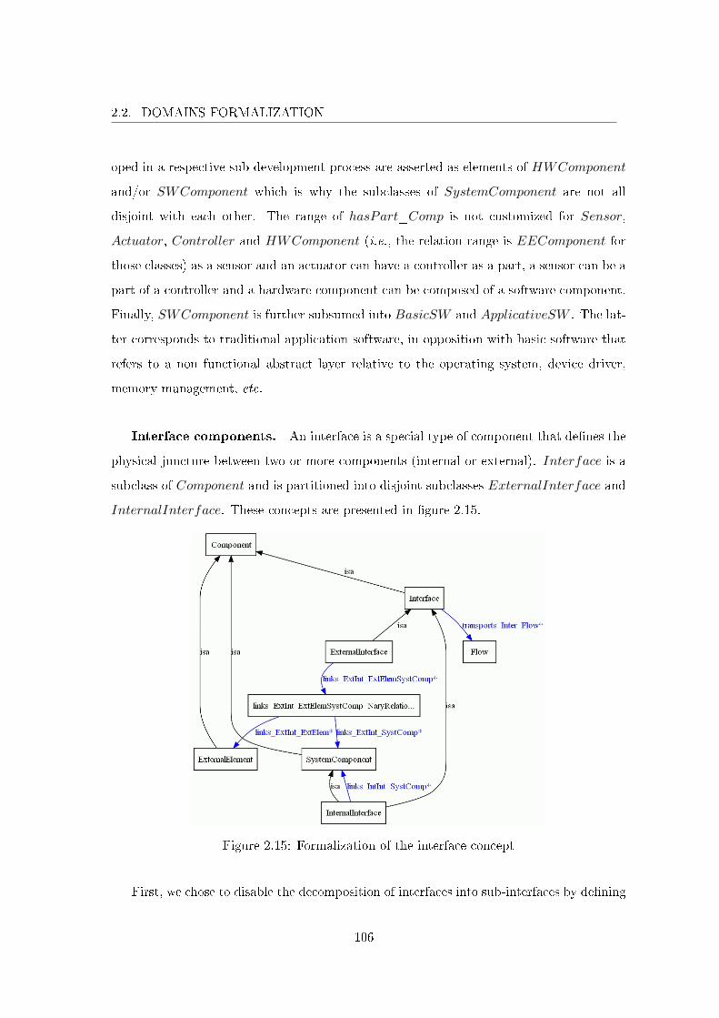
2.2. DOMAINS FORMALIZATION
oped in a respective sub-development process are asserted as elements of HWComponent
and/or SWComponent which is why the subclasses of SystemComponent are not all
disjoint with each other. The range of hasPart_Comp is not customized for Sensor,
Actuator, Controller and HWComponent (i.e., the relation range is EEComponent for
those classes) as a sensor and an actuator can have a controller as a part, a sensor can be a
part of a controller and a hardware component can be composed of a software component.
Finally, SWComponent is further subsumed into BasicSW and ApplicativeSW . The lat-
ter corresponds to traditional application software, in opposition with basic software that
refers to a non functional abstract layer relative to the operating system, device driver,
memory management, etc.
Interface components. An interface is a special type of component that de�nes the
physical juncture between two or more components (internal or external). Interface is a
subclass of Component and is partitioned into disjoint subclasses ExternalInterface and
InternalInterface. These concepts are presented in �gure 2.15.
Figure 2.15: Formalization of the interface concept
First, we chose to disable the decomposition of interfaces into sub-interfaces by de�ning
106
2.2. DOMAINS FORMALIZATION
the cardinality of hasPart_Comp to 0 for the class Interface.
Second, the external/internal distinction does not refer to the system as usual. The
connotation refers to the physical juncture between components and corresponds to inter-
faces that link system components only (internal interfaces) or components which at least
one is an external element (external interfaces). Therefore, an internal interface is a system
component and an external interface can be a system component or an external element
of the system depending on whether its development is the responsibility of the project or
not. Formally, InternalInterface is asserted as a subclass of SystemComponent disjoint
with ExternalElement (see �gure 2.14).
The interface considered as the physical juncture between components is formalized with
respective links properties in �gure 2.15. An internal interface is related to system compo-
nents through link_IntInt_SystComp with InternalInterface and SystemComponent
as domain and co-domain. The relation is constrained with a minimum cardinality of 2.
The relation range is customized to system components that are not interfaces.
For the external interfaces, we introduce an intermediate class links_ExtInt_ExtElem-
SystComp_NaryRelation in order to model the 3-ary relation between ExternalInter-
face, ExternalElement and SystemComponent. As the class models a relation its name
starts with a lowercase letter. The property links_ExtInt_ExtElemSystComp relates
External_Interface with the 3-ary relation as can be seen in �gure 2.15. The property is
given an exact cardinality of 1 (this is equivalent to de�ne a minimum and maximum
cardinality of 1) as an external interface that does not links components is incorrect.
Then properties links_ExtInt_ExtElem and links_ExtInt_SystComp enable to as-
sert which components are linked through external interfaces. The domain of those rela-
tions is links_ExtInt_ExtElemSystComp_NaryRelation. Their range is respectively
constrained to external elements and systems components that are not interfaces (i.e.,
ExternalElement \ Interface and SystemComponent \ Interface). The two correct
cases accounted are either, the external interface links only one external element, which
implies that it also links a system component, or the external interface links two external
elements. Formally, the relation links_ExtInt_ExtElem is only given a minimum cardi-
nality of 1 as the axiomatization in appendix A does not allow to express that the external
107
2.2. DOMAINS FORMALIZATION
interfaces link at least two components with one being an external element.
Finally, an interface is de�ned by the �ows it transports which is formalized with the
property transports_Inter_Flow with Interface and Flow as domain and co-domain.
The relation is given a minimum cardinality of 1 for the class Interface. It is not further
customized for external interfaces as they can transport any type of �ows. For Internal-
Interface, the property range is constrained to InternalF low (that forms with External-
Flow a partition of the class Flow).
2.2.1.5 On Traceability
The main concepts of systems engineering have been presented in the previous sec-
tions. The remaining of the SDD document presents the allocation of the functions on the
constituents and the allocation of the �ows on the interfaces that transport them based
on the functional and physical architectures. Lastly, a traceability table explains how
requirements, functions and constituents are related.
Allowing the veri�cation that all the requirements are taken into account by the design
is one objective of traceability. Recall the de�nition of traceability from section 1.2.1.1.
Traceability: The ability to trace (identify and measure) all the stages that led
to a particular point in a process that consists of a chain of interrelated events.
In this work, traceability is implemented by using the di�erent semantic relations that
have been presented and the ones that relate the main concepts of systems engineering
(presented in this section). As mentioned, a trace corresponds to a sequence of relations.
By traceability we refer to the capability to de�ne such traces which is inherently made
possible by de�ning an ontology. In addition to this implicit capability, the ontology
de�nes a hierarchical structure for the elements of design (i.e., requirements, functions
and components) and has been designed such that traceability is established from the
requirements, through the functions, to the components along with the informal property
that any non leaf element of a hierarchy is taken into account by the next level of abstraction
if and only if all the leaf elements of the hierarchy are related to the next abstraction level.
The cardinality constraints are used to de�ne the existence of an element in relation to
108
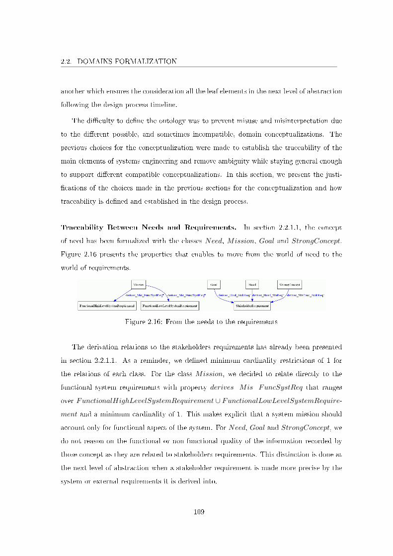
2.2. DOMAINS FORMALIZATION
another which ensures the consideration all the leaf elements in the next level of abstraction
following the design process timeline.
The di�culty to de�ne the ontology was to prevent misuse and misinterpretation due
to the di�erent possible, and sometimes incompatible, domain conceptualizations. The
previous choices for the conceptualization were made to establish the traceability of the
main elements of systems engineering and remove ambiguity while staying general enough
to support di�erent compatible conceptualizations. In this section, we present the justi-
�cations of the choices made in the previous sections for the conceptualization and how
traceability is de�ned and established in the design process.
Traceability Between Needs and Requirements. In section 2.2.1.1, the concept
of need has been formalized with the classes Need, Mission, Goal and StrongConcept.
Figure 2.16 presents the properties that enables to move from the world of need to the
world of requirements.
Figure 2.16: From the needs to the requirements
The derivation relations to the stakeholders requirements has already been presented
in section 2.2.1.1. As a reminder, we de�ned minimum cardinality restrictions of 1 for
the relations of each class. For the class Mission, we decided to relate directly to the
functional system requirements with property derives_Mis_FuncSystReq that ranges
over FunctionalHighLevelSystemRequirement ∪ FunctionalLowLevelSystemRequire-
ment and a minimum cardinality of 1. This makes explicit that a system mission should
account only for functional aspect of the system. For Need, Goal and StrongConcept, we
do not reason on the functional or non functional quality of the information recorded by
those concept as they are related to stakeholders requirements. This distinction is done at
the next level of abstraction when a stakeholder requirement is made more precise by the
system or external requirements it is derived into.
109
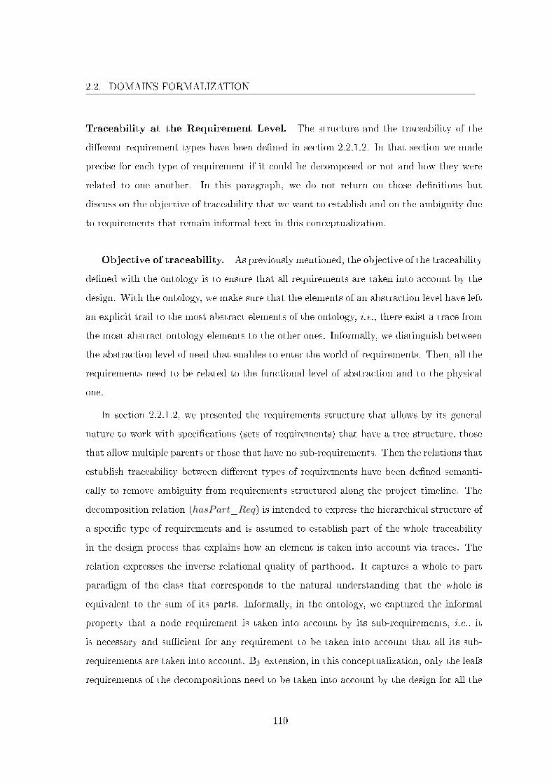
2.2. DOMAINS FORMALIZATION
Traceability at the Requirement Level. The structure and the traceability of the
di�erent requirement types have been de�ned in section 2.2.1.2. In that section we made
precise for each type of requirement if it could be decomposed or not and how they were
related to one another. In this paragraph, we do not return on those de�nitions but
discuss on the objective of traceability that we want to establish and on the ambiguity due
to requirements that remain informal text in this conceptualization.
Objective of traceability. As previously mentioned, the objective of the traceability
de�ned with the ontology is to ensure that all requirements are taken into account by the
design. With the ontology, we make sure that the elements of an abstraction level have left
an explicit trail to the most abstract elements of the ontology, i.e., there exist a trace from
the most abstract ontology elements to the other ones. Informally, we distinguish between
the abstraction level of need that enables to enter the world of requirements. Then, all the
requirements need to be related to the functional level of abstraction and to the physical
one.
In section 2.2.1.2, we presented the requirements structure that allows by its general
nature to work with speci�cations (sets of requirements) that have a tree structure, those
that allow multiple parents or those that have no sub-requirements. Then the relations that
establish traceability between di�erent types of requirements have been de�ned semanti-
cally to remove ambiguity from requirements structured along the project timeline. The
decomposition relation (hasPart_Req) is intended to express the hierarchical structure of
a speci�c type of requirements and is assumed to establish part of the whole traceability
in the design process that explains how an element is taken into account via traces. The
relation expresses the inverse relational quality of parthood. It captures a whole to part
paradigm of the class that corresponds to the natural understanding that the whole is
equivalent to the sum of its parts. Informally, in the ontology, we captured the informal
property that a node requirement is taken into account by its sub-requirements, i.e., it
is necessary and su�cient for any requirement to be taken into account that all its sub-
requirements are taken into account. By extension, in this conceptualization, only the leafs
requirements of the decompositions need to be taken into account by the design for all the
110
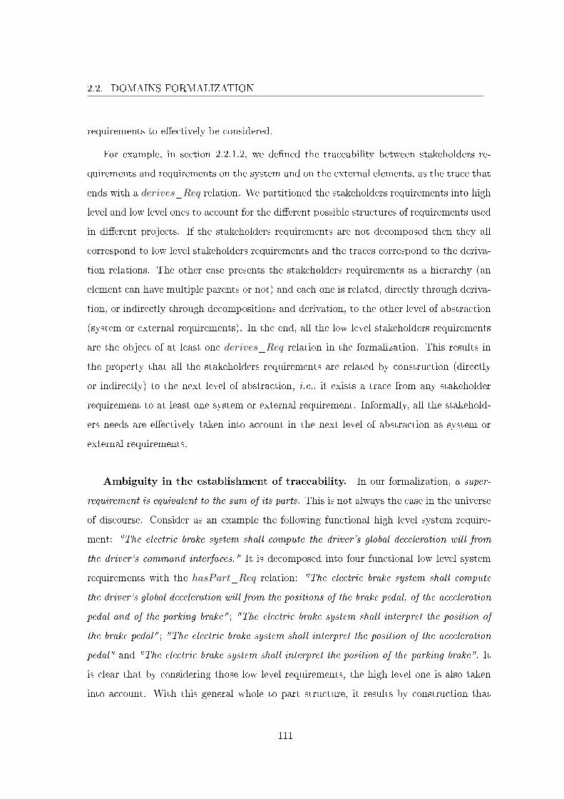
2.2. DOMAINS FORMALIZATION
requirements to e�ectively be considered.
For example, in section 2.2.1.2, we de�ned the traceability between stakeholders re-
quirements and requirements on the system and on the external elements, as the trace that
ends with a derives_Req relation. We partitioned the stakeholders requirements into high
level and low level ones to account for the di�erent possible structures of requirements used
in di�erent projects. If the stakeholders requirements are not decomposed then they all
correspond to low level stakeholders requirements and the traces correspond to the deriva-
tion relations. The other case presents the stakeholders requirements as a hierarchy (an
element can have multiple parents or not) and each one is related, directly through deriva-
tion, or indirectly through decompositions and derivation, to the other level of abstraction
(system or external requirements). In the end, all the low level stakeholders requirements
are the object of at least one derives_Req relation in the formalization. This results in
the property that all the stakeholders requirements are related by construction (directly
or indirectly) to the next level of abstraction, i.e., it exists a trace from any stakeholder
requirement to at least one system or external requirement. Informally, all the stakehold-
ers needs are e�ectively taken into account in the next level of abstraction as system or
external requirements.
Ambiguity in the establishment of traceability. In our formalization, a super-
requirement is equivalent to the sum of its parts. This is not always the case in the universe
of discourse. Consider as an example the following functional high level system require-
ment: "The electric brake system shall compute the driver's global deceleration will from
the driver's command interfaces." It is decomposed into four functional low level system
requirements with the hasPart_Req relation: "The electric brake system shall compute
the driver's global deceleration will from the positions of the brake pedal, of the acceleration
pedal and of the parking brake" ; "The electric brake system shall interpret the position of
the brake pedal" ; "The electric brake system shall interpret the position of the acceleration
pedal" and "The electric brake system shall interpret the position of the parking brake". It
is clear that by considering those low level requirements, the high level one is also taken
into account. With this general whole to part structure, it results by construction that
111
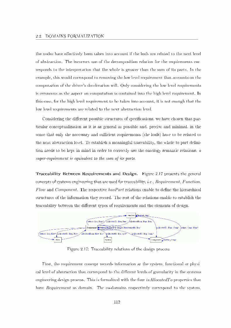
2.2. DOMAINS FORMALIZATION
the nodes have e�ectively been taken into account if the leafs are related to the next level
of abstraction. The incorrect use of the decomposition relation for the requirements cor-
responds to the interpretation that the whole is greater than the sum of its parts. In the
example, this would correspond to removing the low level requirement that accounts on the
computation of the driver's deceleration will. Only considering the low level requirements
is erroneous as the aspect on computation is contained into the high level requirement. In
this case, for the high level requirement to be taken into account, it is not enough that the
low level requirements are related to the next abstraction level.
Considering the di�erent possible structures of speci�cations, we have chosen that par-
ticular conceptualization as it is as general as possible and, precise and minimal, in the
sense that only the necessary and su�cient requirements (the leafs) have to be related to
the next abstraction level. To establish a meaningful traceability, the whole to part de�ni-
tion needs to be kept in mind in order to correctly use the ontology semantic relations: a
super-requirement is equivalent to the sum of its parts.
Traceability Between Requirements and Design. Figure 2.17 presents the general
concepts of systems engineering that are used for traceability, i.e., Requirement, Function,
Flow and Component. The respective hasPart relations enable to de�ne the hierarchical
structures of the information they record. The rest of the relations enable to establish the
traceability between the di�erent types of requirements and the elements of design.
Figure 2.17: Traceability relations of the design process
First, the requirement concept records information at the system, functional or physi-
cal level of abstraction that correspond to the di�erent levels of granularity in the systems
engineering design process. This is formalized with the four isAllocatedTo properties that
have Requirement as domain. The co-domains respectively correspond to the system,
112
2.2. DOMAINS FORMALIZATION
functional and physical level, i.e., System, Function and Flow, Component. Those prop-
erties capture a partition of the requirements at these di�erent levels of detail therefore all
the requirements (except the stakeholders requirements) are allocated either to the system
or some functions or some �ows or some components (2.25). Moreover, those properties
(except isAllocatedTo_Req_Syst) contribute to the establishment of traceability between
requirements and design (they directly capture how an element of design is an answer to
the consideration of a requirement).
¬StakeholderRequirement(x) ∧(isAllocatedTo_Req_Syst(x, syst)⊕ isAllocatedTo_Req_Func(x, func)⊕isAllocatedTo_Req_Flow(x, flow)⊕ isAllocatedTo_Req_Comp(x, comp))
(2.25)
Second, the properties derives_Req and isCharacterizedBy_Req have been presented
in section 2.2.1.2 and are used to establish the traceability between the di�erent types of
requirements illustrated in �gures 2.4, 2.5, 2.6, 2.7 and 2.8. Informally, the di�erent types
of requirements are used respectively to record information corresponding to the system or
to external system elements at system, functional or physical level of detail.
Third, some requirements can be involved by properties deduces_Req_Func and /
or deduces_Req_Flow. They semantically record the abstraction change from the re-
quirement to the system functional architecture. In terms of traceability those properties
capture how the requirements are realized by a solution for the system at functional level,
in other words, how requirements are taken into account by functions and �ows. Properties
isDeducedFrom_Func_Req and isDeducedFrom_Flow_Req express that a function or
a �ow come from a requirement and they are used to establish backwards traceability (i.e.,
all the relevant functions and �ows can be related to a requirement).
Finally, the abstraction change from the functional to the physical level is formal-
ized with isAllocatedTo_Func_Comp. In terms of traceability, the previous relation
deduces_Req_Func captures how the requirements are realized by a solution for the sys-
tem at the functional level. The property isAllocatedTo_Func_Comp captures how the
the solution at the functional level is realized by a solution at the physical level. By tran-
sitivity, those two relations capture how the requirements are taken into account by the
components (as they realize the functions that themselves take into account those require-
ments). The property realizes_Comp_Func expresses for a component the functions it
113
2.2. DOMAINS FORMALIZATION
realizes. This property has a minimum cardinality of 1 for Component, as a component
that does not realize any function is useless.
The design process develops a solution for the system under development. This solution
is described with the ontology main concepts that correspond to design process activities,
see �gure 2.1. The speci�cation activity produces textual requirements. In the design
process, these requirements are of utmost importance and need to be of high quality, i.e.,
precise as de�ned by the ontology. As our objective is to ascertain that all requirements
have e�ectively been considered by the development process, the traces we want to establish
shall record changes from system level of abstraction, to functional and physical ones. We
have the usual trail from requirement, to function, to component and also traces that
record the consideration of non functional requirements. The �rst kind of trace actually
starts with the functional requirements and explains how they are taken into account by
the functional architecture, and then how the functions of the functional architecture are
taken into account by system components. The non functional aspect of the system is
more problematic. The consideration of non functional system requirements by the design
is not as straightforward as the functional counterpart because there is not yet a precise
conceptualization of the di�erent types of non functional requirements and how they are
taken into account by the design. Nevertheless, the main idea for the non functional
requirements consideration is that they are expressed at the system level of abstraction
and they should trace to the adequate level of abstraction (functional or physical).
Another kind of traces concerns backwards traceability where we ensure that elements
of design e�ectively trace back to requirements. This is important to describe as downwards
and backwards traceability do not de�ne a bijection in the ontology. In this paragraph,
we presented traceability at the level of detail presented in �gure 2.17. The remaining of
this section presents traceability at the system, functional and physical level by explaining
all the relevant relations in �gure 2.17. Note that section 2.2.1.6 gives more detail on non
functional requirements.
Traceability at the System Level. System requirements (see �gure 2.7) correspond to
requirements at system level. They express the stakeholders needs. These needs are either
114

2.2. DOMAINS FORMALIZATION
stakeholders requirements or system missions. They are related to system requirements
through derives_Req (section 2.2.1.2) or derives_Mis_FuncSystReq (previously in this
section). In section 2.2.1.2, we explained that the stakeholders requirements were the most
abstract type of requirements. As such, they can record information at any level of de-
tail (system, functional or physical level) and the allocation relations have been disabled
to consider this imprecision of the concept (isAllocatedTo_Req_Syst, isAllocatedTo_-
Req_Func, isAllocatedTo_Req_Flow and isAllocatedTo_Req_Comp have a cardinal-
ity of 0 for StakeholderRequirement). The traceability at the system level corresponds
simply to system requirements that de�ne some characteristics of the system under devel-
opment. Figure 2.18 only presents relations that are used to establish a trace from the
system requirements to the system.
Figure 2.18: From the system requirements to the system
In this conceptualization, all system requirements are related to the system under de-
velopment. This is formalized by giving an exact cardinality of 1 (minimum and maximum
cardinality of 1) to the isAllocatedTo_Req_Syst property for the SystemRequirement
class (2.26). The other relations of allocation (isAllocatedTo_Req_Func, isAllocated-
To_Req_Flow and isAllocatedTo_Req_Comp) are disabled for the class (the relations
are constrained with a cardinality of 0 for SystemRequirement). Note that this is con-
sistent with axiom (2.25). An informal rule to show that a requirement is at system level
is that system requirements statements start with: "The ___ system shall ...". The ca-
pability to allocate a set of system requirements to the system was also requested and
corresponds to axiom (2.27).
∃! y SystemRequirement(x)⇒ isAllocatedTo_Req_Syst(x, y) (2.26)
SystemRequirement(x) ∧ hasPart_Req(x, y) ∧isAllocatedTo_Req_Syst(x, z)⇒ isAllocatedTo_Req_Syst(y, z)
(2.27)
115
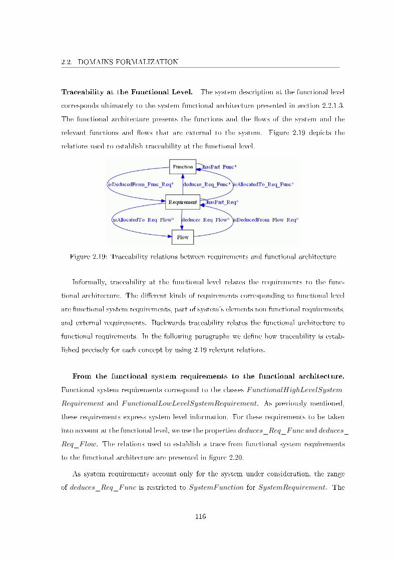
2.2. DOMAINS FORMALIZATION
Traceability at the Functional Level. The system description at the functional level
corresponds ultimately to the system functional architecture presented in section 2.2.1.3.
The functional architecture presents the functions and the �ows of the system and the
relevant functions and �ows that are external to the system. Figure 2.19 depicts the
relations used to establish traceability at the functional level.
Figure 2.19: Traceability relations between requirements and functional architecture
Informally, traceability at the functional level relates the requirements to the func-
tional architecture. The di�erent kinds of requirements corresponding to functional level
are functional system requirements, part of system's elements non functional requirements,
and external requirements. Backwards traceability relates the functional architecture to
functional requirements. In the following paragraphs we de�ne how traceability is estab-
lished precisely for each concept by using 2.19 relevant relations.
From the functional system requirements to the functional architecture.
Functional system requirements correspond to the classes FunctionalHighLevelSystem-
Requirement and FunctionalLowLevelSystemRequirement. As previously mentioned,
these requirements express system level information. For these requirements to be taken
into account at the functional level, we use the properties deduces_Req_Func and deduces_-
Req_Flow. The relations used to establish a trace from functional system requirements
to the functional architecture are presented in �gure 2.20.
As system requirements account only for the system under consideration, the range
of deduces_Req_Func is restricted to SystemFunction for SystemRequirement. The
116
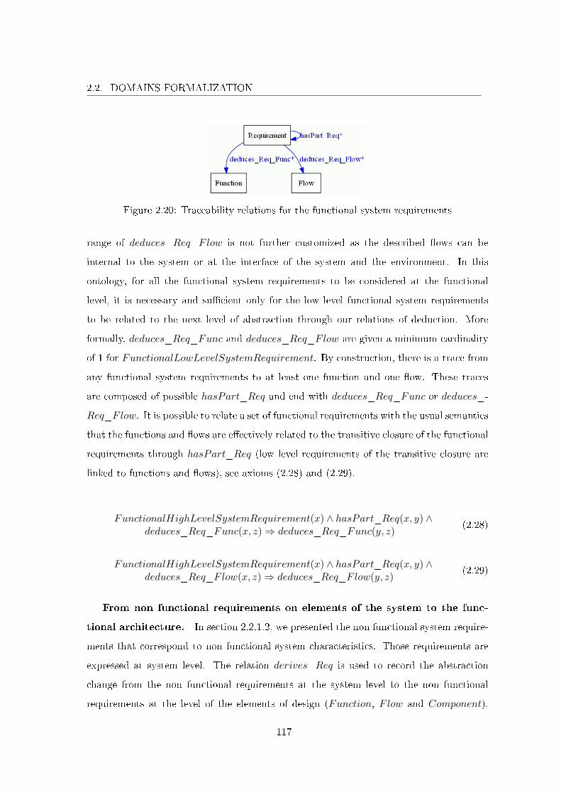
2.2. DOMAINS FORMALIZATION
Figure 2.20: Traceability relations for the functional system requirements
range of deduces_Req_Flow is not further customized as the described �ows can be
internal to the system or at the interface of the system and the environment. In this
ontology, for all the functional system requirements to be considered at the functional
level, it is necessary and su�cient only for the low level functional system requirements
to be related to the next level of abstraction through our relations of deduction. More
formally, deduces_Req_Func and deduces_Req_Flow are given a minimum cardinality
of 1 for FunctionalLowLevelSystemRequirement. By construction, there is a trace from
any functional system requirements to at least one function and one �ow. These traces
are composed of possible hasPart_Req and end with deduces_Req_Func or deduces_-
Req_Flow. It is possible to relate a set of functional requirements with the usual semantics
that the functions and �ows are e�ectively related to the transitive closure of the functional
requirements through hasPart_Req (low level requirements of the transitive closure are
linked to functions and �ows), see axioms (2.28) and (2.29).
FunctionalHighLevelSystemRequirement(x) ∧ hasPart_Req(x, y) ∧deduces_Req_Func(x, z)⇒ deduces_Req_Func(y, z)
(2.28)
FunctionalHighLevelSystemRequirement(x) ∧ hasPart_Req(x, y) ∧deduces_Req_Flow(x, z)⇒ deduces_Req_Flow(y, z)
(2.29)
From non functional requirements on elements of the system to the func-
tional architecture. In section 2.2.1.2, we presented the non functional system require-
ments that correspond to non functional system characteristics. Those requirements are
expressed at system level. The relation derives_Req is used to record the abstraction
change from the non functional requirements at the system level to the non functional
requirements at the level of the elements of design (Function, Flow and Component).
117
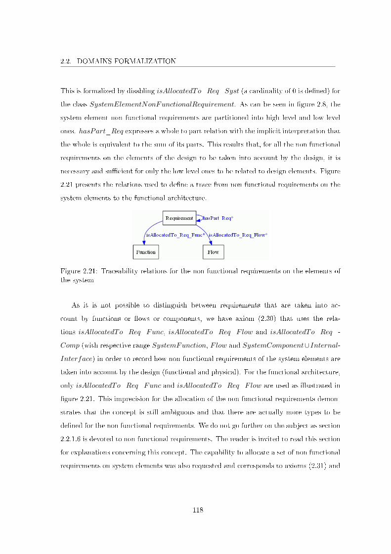
2.2. DOMAINS FORMALIZATION
This is formalized by disabling isAllocatedTo_Req_Syst (a cardinality of 0 is de�ned) for
the class SystemElementNonFunctionalRequirement. As can be seen in �gure 2.8, the
system element non functional requirements are partitioned into high level and low level
ones. hasPart_Req expresses a whole to part relation with the implicit interpretation that
the whole is equivalent to the sum of its parts. This results that, for all the non functional
requirements on the elements of the design to be taken into account by the design, it is
necessary and su�cient for only the low level ones to be related to design elements. Figure
2.21 presents the relations used to de�ne a trace from non functional requirements on the
system elements to the functional architecture.
Figure 2.21: Traceability relations for the non functional requirements on the elements ofthe system
As it is not possible to distinguish between requirements that are taken into ac-
count by functions or �ows or components, we have axiom (2.30) that uses the rela-
tions isAllocatedTo_Req_Func, isAllocatedTo_Req_Flow and isAllocatedTo_Req_-
Comp (with respective range SystemFunction, Flow and SystemComponent∪Internal-
Interface) in order to record how non functional requirements of the system elements are
taken into account by the design (functional and physical). For the functional architecture,
only isAllocatedTo_Req_Func and isAllocatedTo_Req_Flow are used as illustrated in
�gure 2.21. This imprecision for the allocation of the non functional requirements demon-
strates that the concept is still ambiguous and that there are actually more types to be
de�ned for the non functional requirements. We do not go further on the subject as section
2.2.1.6 is devoted to non functional requirements. The reader is invited to read this section
for explanations concerning this concept. The capability to allocate a set of non functional
requirements on system elements was also requested and corresponds to axioms (2.31) and
118
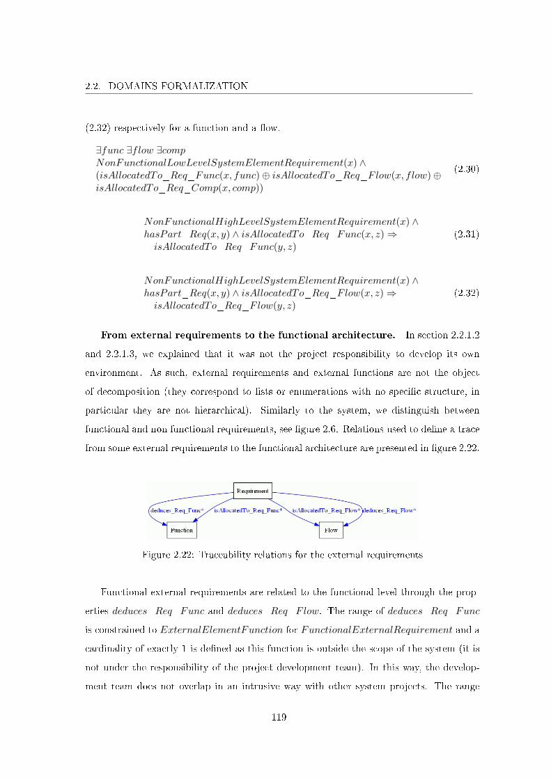
2.2. DOMAINS FORMALIZATION
(2.32) respectively for a function and a �ow.
∃func ∃flow ∃compNonFunctionalLowLevelSystemElementRequirement(x) ∧(isAllocatedTo_Req_Func(x, func)⊕ isAllocatedTo_Req_Flow(x, flow)⊕isAllocatedTo_Req_Comp(x, comp))
(2.30)
NonFunctionalHighLevelSystemElementRequirement(x) ∧hasPart_Req(x, y) ∧ isAllocatedTo_Req_Func(x, z)⇒isAllocatedTo_Req_Func(y, z)
(2.31)
NonFunctionalHighLevelSystemElementRequirement(x) ∧hasPart_Req(x, y) ∧ isAllocatedTo_Req_Flow(x, z)⇒isAllocatedTo_Req_Flow(y, z)
(2.32)
From external requirements to the functional architecture. In section 2.2.1.2
and 2.2.1.3, we explained that it was not the project responsibility to develop its own
environment. As such, external requirements and external functions are not the object
of decomposition (they correspond to lists or enumerations with no speci�c structure, in
particular they are not hierarchical). Similarly to the system, we distinguish between
functional and non functional requirements, see �gure 2.6. Relations used to de�ne a trace
from some external requirements to the functional architecture are presented in �gure 2.22.
Figure 2.22: Traceability relations for the external requirements
Functional external requirements are related to the functional level through the prop-
erties deduces_Req_Func and deduces_Req_Flow. The range of deduces_Req_Func
is constrained to ExternalElementFunction for FunctionalExternalRequirement and a
cardinality of exactly 1 is de�ned as this function is outside the scope of the system (it is
not under the responsibility of the project development team). In this way, the develop-
ment team does not overlap in an intrusive way with other system projects. The range
119

2.2. DOMAINS FORMALIZATION
of deduces_Req_Flow is constrained to ExternalF low as �ows produced or consumed
by external functions are outside the scope of the system. A minimum cardinality of 1 is
de�ned to constrain the relation for FunctionalExternalRequirement. For the non func-
tional external requirements, it is not possible to distinguish between requirements that
are taken into account by functions or �ows or components. isAllocatedTo_Req_Func
and isAllocatedTo_Req_Flow are the relations used to relate non functional external
requirements and the functional architecture as shown in �gure 2.22. The ambiguity for
the concept is not solved but we de�ne axiom (2.33) that explains the allocation of a non
functional external requirements to either functions or �ows or components. The ranges of
isAllocatedTo_Req_Func, isAllocatedTo_Req_Flow and isAllocatedTo_Req_Comp
are respectively constrained to ExternalElementFunction, ExternalF low and External-
Element ∪ ExternalInterface.
∃func ∃flow ∃comp NonFunctionalExternalRequirement(x) ∧isAllocatedTo_Req_Func(x, func)⊕ isAllocatedTo_Req_Flow(x, flow)⊕isAllocatedTo_Req_Comp(x, comp))
(2.33)
From the functional architecture to requirements. As previously mentioned,
downwards and backwards traceability do not de�ne a bijection. As such, we cannot use
the same relations to ensure that the functional architecture is e�ectively related to the
requirements.
For now, with downwards traceability, we ensured that the stakeholders needs were
expressed as requirements on the system and on the system external elements. Then,
the functional part of these requirements can trace to the functional architecture directly.
Using cardinality constraints and requirements structure, we ensured that all the relevant
functional requirements (low level functional system requirements and functional external
requirements) were taken into account by the functional architecture (functions and �ows).
The converse is not true as it is still possible to have some functions and / or some �ows
de�ned in the functional architecture that are not related to any functional requirements.
To ensure that this is not possible, we use the relations isDeducedFrom_Func_Req and
isDeducedFrom_Flow_Req presented in �gure 2.23.
As the �ows are not the object of decomposition, we de�ne isDeducedFrom_Flow_-
120
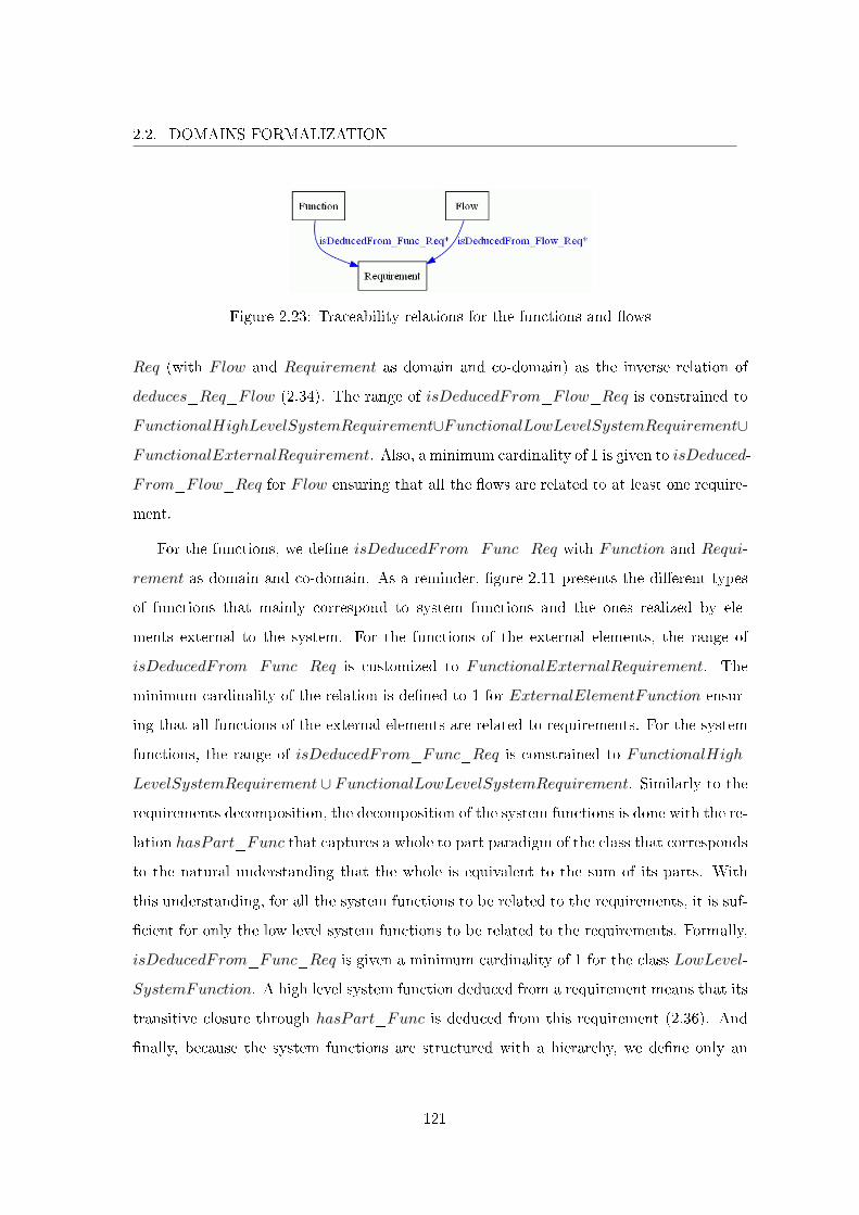
2.2. DOMAINS FORMALIZATION
Figure 2.23: Traceability relations for the functions and �ows
Req (with Flow and Requirement as domain and co-domain) as the inverse relation of
deduces_Req_Flow (2.34). The range of isDeducedFrom_Flow_Req is constrained to
FunctionalHighLevelSystemRequirement∪FunctionalLowLevelSystemRequirement∪
FunctionalExternalRequirement. Also, a minimum cardinality of 1 is given to isDeduced-
From_Flow_Req for Flow ensuring that all the �ows are related to at least one require-
ment.
For the functions, we de�ne isDeducedFrom_Func_Req with Function and Requi-
rement as domain and co-domain. As a reminder, �gure 2.11 presents the di�erent types
of functions that mainly correspond to system functions and the ones realized by ele-
ments external to the system. For the functions of the external elements, the range of
isDeducedFrom_Func_Req is customized to FunctionalExternalRequirement. The
minimum cardinality of the relation is de�ned to 1 for ExternalElementFunction ensur-
ing that all functions of the external elements are related to requirements. For the system
functions, the range of isDeducedFrom_Func_Req is constrained to FunctionalHigh-
LevelSystemRequirement ∪ FunctionalLowLevelSystemRequirement. Similarly to the
requirements decomposition, the decomposition of the system functions is done with the re-
lation hasPart_Func that captures a whole to part paradigm of the class that corresponds
to the natural understanding that the whole is equivalent to the sum of its parts. With
this understanding, for all the system functions to be related to the requirements, it is suf-
�cient for only the low level system functions to be related to the requirements. Formally,
isDeducedFrom_Func_Req is given a minimum cardinality of 1 for the class LowLevel-
SystemFunction. A high level system function deduced from a requirement means that its
transitive closure through hasPart_Func is deduced from this requirement (2.36). And
�nally, because the system functions are structured with a hierarchy, we de�ne only an
121
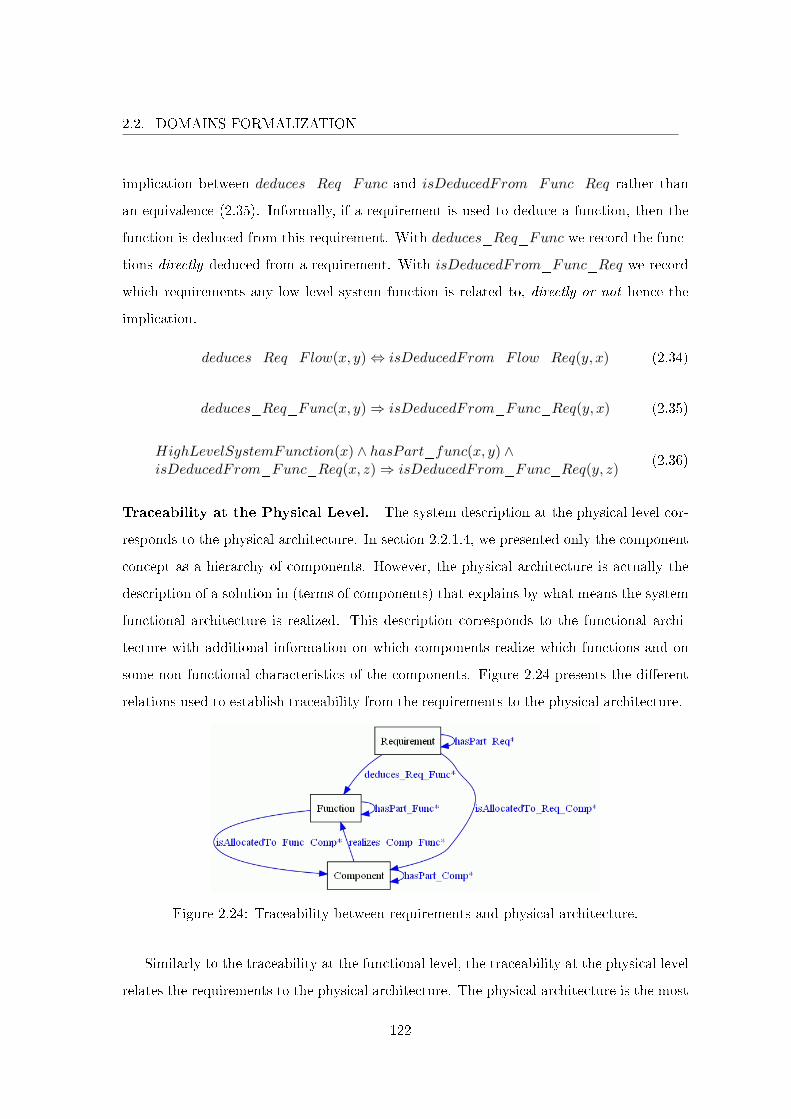
2.2. DOMAINS FORMALIZATION
implication between deduces_Req_Func and isDeducedFrom_Func_Req rather than
an equivalence (2.35). Informally, if a requirement is used to deduce a function, then the
function is deduced from this requirement. With deduces_Req_Func we record the func-
tions directly deduced from a requirement. With isDeducedFrom_Func_Req we record
which requirements any low level system function is related to, directly or not hence the
implication.
deduces_Req_Flow(x, y)⇔ isDeducedFrom_Flow_Req(y, x) (2.34)
deduces_Req_Func(x, y)⇒ isDeducedFrom_Func_Req(y, x) (2.35)
HighLevelSystemFunction(x) ∧ hasPart_func(x, y) ∧isDeducedFrom_Func_Req(x, z)⇒ isDeducedFrom_Func_Req(y, z)
(2.36)
Traceability at the Physical Level. The system description at the physical level cor-
responds to the physical architecture. In section 2.2.1.4, we presented only the component
concept as a hierarchy of components. However, the physical architecture is actually the
description of a solution in (terms of components) that explains by what means the system
functional architecture is realized. This description corresponds to the functional archi-
tecture with additional information on which components realize which functions and on
some non functional characteristics of the components. Figure 2.24 presents the di�erent
relations used to establish traceability from the requirements to the physical architecture.
Figure 2.24: Traceability between requirements and physical architecture.
Similarly to the traceability at the functional level, the traceability at the physical level
relates the requirements to the physical architecture. The physical architecture is the most
122
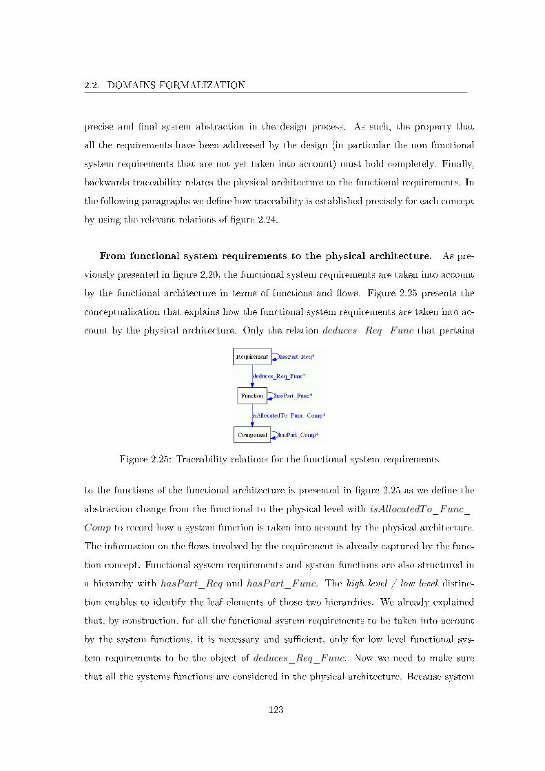
2.2. DOMAINS FORMALIZATION
precise and �nal system abstraction in the design process. As such, the property that
all the requirements have been addressed by the design (in particular the non functional
system requirements that are not yet taken into account) must hold completely. Finally,
backwards traceability relates the physical architecture to the functional requirements. In
the following paragraphs we de�ne how traceability is established precisely for each concept
by using the relevant relations of �gure 2.24.
From functional system requirements to the physical architecture. As pre-
viously presented in �gure 2.20, the functional system requirements are taken into account
by the functional architecture in terms of functions and �ows. Figure 2.25 presents the
conceptualization that explains how the functional system requirements are taken into ac-
count by the physical architecture. Only the relation deduces_Req_Func that pertains
Figure 2.25: Traceability relations for the functional system requirements
to the functions of the functional architecture is presented in �gure 2.25 as we de�ne the
abstraction change from the functional to the physical level with isAllocatedTo_Func_-
Comp to record how a system function is taken into account by the physical architecture.
The information on the �ows involved by the requirement is already captured by the func-
tion concept. Functional system requirements and system functions are also structured in
a hierarchy with hasPart_Req and hasPart_Func. The high level / low level distinc-
tion enables to identify the leaf elements of those two hierarchies. We already explained
that, by construction, for all the functional system requirements to be taken into account
by the system functions, it is necessary and su�cient, only for low level functional sys-
tem requirements to be the object of deduces_Req_Func. Now we need to make sure
that all the systems functions are considered in the physical architecture. Because system
123
2.2. DOMAINS FORMALIZATION
functions are inside the system perimeter, they need to be taken into account by system
components (including interfaces). The range of isAllocatedTo_Func_Comp is therefore
restricted to SystemComponent ∪ Interface for the class SystemFunction. Similarly to
hasPart_Req, hasPart_Func captures a whole to part paradigm that corresponds to the
whole being equivalent to the sum of its parts. Given this interpretation, for all the system
functions to be taken into account by the physical architecture, it is necessary and su�-
cient that all low level system functions are related to components. Allocating the same
function on more than one component is incorrect. This actually corresponds to an error
in the universe of discourse as such functions actually correspond to two di�erent functions
that happens to be similar. Formally, an exact cardinality of 1 is given to isAllocated-
To_Func_Comp for LowLevelSystemFunction. As usual the capability to allocate a
set of functions was desired with the usual semantic that it is e�ectively the transitive
closure of the high level system function through hasPart_Func (in particular the low
level system functions that belong to this transitive closure) that is allocated to the con-
cerned component (axiom 2.37). Finally, the traces that are de�ned using hasPart_Req,
deduces_Req_Func, hasPart_Func and isAllocatedTo_Func_Comp ensures that all
the functional system requirements have actually been taken into account by the physical
architecture.
HighLevelSystemFunction(x) ∧ hasPart_Func(x, y) ∧isAllocatedTo_Func_Comp(x, z)⇒ isAllocatedTo_Func_Comp(y, z)
(2.37)
From non functional requirements on system elements to the physical ar-
chitecture. As a reminder, part of the non functional requirements on the elements of
design corresponds to the system description at functional level (see �gure 2.21). As al-
ready mentioned, it is not possible to distinguish between the requirements that are taken
into account by functions or �ows or components however the non functional requirement
should be precise enough to be related exclusively to functions or �ows or components
(2.30). To record how a non functional requirement is taken into account by the physical
architecture, we use isAllocatedTo_Req_Comp (see �gure 2.24. Section 2.2.1.6 addresses
the non functional requirements so we do not elaborate on the subject. As usual, the capa-
bility to allocate a set of non functional requirements (at the physical level) to a component
124
2.2. DOMAINS FORMALIZATION
is provided (2.38).
NonFunctionalHighLevelSystemElementRequirement(x) ∧hasPart_Req(x, y) ∧ isAllocatedTo_Req_Comp(x, z)⇒isAllocatedTo_Req_Comp(y, z)
(2.38)
From external requirements to the physical architecture. As the develop-
ment of the environment is not the responsibility of the project, decomposition of external
elements is not done in the ontology. Similarly to system requirements, external require-
ments are partitioned between functional and non functional ones (see �gure 2.6) and
their traceability is established using the same relations presented before. The functional
external requirements are traced to the physical architecture indirectly through the func-
tional architecture with relations deduces_Req_Func and isAllocatedTo_Func_Comp
(see �gure 2.25). Their range is respectively customized to ExternalElementFunction
and ExternalElement ∪ExternalInterface recording how a functional external require-
ment is related to an external function which is taken into account by the physical ar-
chitecture. An external function that is not allocated to an external element is incorrect
so isAllocatedTo_Func_Comp is given an exact cardinality of 1. Concerning the non
functional external requirements, they are related to the physical architecture with is-
AllocatedTo_Req_Comp which ranges over ExternalElement∪ExternalInterface. As
previously de�ned, the non functional external requirements are allocated to either func-
tions or �ows or components (2.33).
From the physical architecture to requirements. With downwards traceability,
we ensured that it was possible to follow the trail left by any requirement for its consider-
ation by the functional and / or physical architectures. Conversely, we have to make sure
that all the components of the physical architecture are e�ectively related to some require-
ments. We use property realizes_Comp_Func to record for a component the functions
it realizes. This property has a minimum cardinality of 1 for Component as a component
that does not realize any function is incorrect in our conceptualization. A component real-
izes the functions that are allocated to it (2.39) and a component that is decomposed into
subcomponents realizes the functions of its subcomponents (2.40). Finally, we customized
the range of realizes_Comp_Func for SystemComponent and ExternalElement respec-
125
2.2. DOMAINS FORMALIZATION
tively to SystemFunction and ExternalElementFunction.
Function(x) ∧ isAllocatedTo_Func_Comp(x, y)⇒realizes_Comp_Func(y, x)
(2.39)
Component(x) ∧hasPart_Comp(x, y) ∧ realizes_Comp_Func(y, z)⇒realizes_Comp_Func(x, z)
(2.40)
2.2.1.6 On Non Functional Requirements
In section 2.2.1.5 we presented how the requirements were interrelated with the elements
of design. The consideration of functional requirements is straightforward. They result
into identi�ed elements of design (i.e., functions, �ows and components, see �gure 2.25)
with adequate semantic. Informally, they describe some functional characteristics that
correspond to some functions and �ows. These functions and �ows are designed into a
functional architecture by describing for each function the �ow it consumes and produces.
Then this functional architecture is realized by de�ning the components that implement
those functions. As we were mainly interested in the functional aspect of the system, we
did not make any attempt to be as explicit with non functional requirements. The main
encountered di�culties concern, on the one hand, the number of di�erent types of non
functional requirements and, on the other hand, the intentional limited expressive power
given by axiomatization in appendix A. We therefore opted to formalize the non functional
requirements in a general manner by recording how they were taken into account by the
elements of design with respective allocation properties on the system, functions, �ows
and components (see �gure 2.17 and axiom (2.25)). This section explains how the non
functional requirements concept are intended to be manipulated in the ontology and we
give some leads for their further formalization.
Formalization of Non Functional Requirements. In the following, we describe the
formalization of system non functional requirements. Those descriptions are similar for
the non functional requirements that are relevant to the environment. As a �rst attempt
to capture the di�erent types of non functional requirements, we de�ned hasType_Req
as an attribute of a requirement. The relation ranges over an enumerated set that de�nes
126
2.2. DOMAINS FORMALIZATION
the type of the non functional requirement that we call constraint. We listed Temporal
performance, Cost and Weight. For each class of requirement (see �gures 2.6, 2.7 and 2.8)
we give a minimum cardinality of 0 or 1 to hasType_Req depending on the requirement
being functional or not. As we have seen in section 2.2.1.5, a non functional requirement is
�rst allocated to the system and then needs to be addressed by the architecture (functional
or physical).
Temporal performance constraint. The notion of temporal performance con-
straint expresses how much time is needed to perform a task. It is associated to the
functional aspect of the system therefore a requirement with information on temporal
performance is related to exactly one functional system requirement through characte-
rizes_Req (see �gure 2.3). Given the axiomatization in appendix A, it is not possible
to customize the relation just for the non functional requirements with temporal perfor-
mance type so we have axiom (2.41). In order for all the systems requirements to be
related to temporal aspects, it is necessary and su�cient for all the low level ones to be
related to a temporal constraint. We de�ne characterizes_Req as the inverse property of
isCharacterizedBy_Req (2.42) and constrain the former relation with a cardinality of 1
for the functional low level system requirements. This enables to describe at system level
temporal constraints corresponding to functional requirements. For example, we have the
following non functional requirement that characterizes a similar functional requirement
that does not describe the temporal performance aspect: "The electric brake system shall
compute the driver's global deceleration will from the driver's command interfaces in less
than 0.02 seconds." This temporal performance needs to be taken into account at design
level. The non functional requirement at system level is expressed at the architectural
level by using derives_Req: "Computing the driver's global deceleration request shall be
performed in less than or equal to 0.02 seconds." In this particular case, the non functional
requirement on the system elements corresponds to the functions that are deduced from
the functional requirement. In this example we have only one function with the following
label: "Compute driver's global deceleration request". The correspondence is made explicit
by allocating the requirement to the function with isAllocatedTo_Req_Func. In the end,
127

2.2. DOMAINS FORMALIZATION
a non functional requirement on system elements, that is derived from a non functional
system requirement which itself characterizes a functional requirement, is allocated to the
functions deduced from the functional requirement (2.43).
∃! y Requirement(x) ∧ hasType_Req(x, ”Temporalperformance”)⇒characterizes_Req(x, y)
(2.41)
Requirement(x) ∧ characterizes_Req(x, y)⇔ isCharacterizedBy_Req(y, x) (2.42)
hasType_Req(x, ”Temporalperformance”) ∧ characterizes_Req(x, y) ∧derives_Req(x, z) ∧ deduces_Func(y, f)⇒ isAllocatedTo_Req_Func(z, f)
(2.43)
In order to formalize the concept of temporal performance in terms of semantic rela-
tions, we chose to de�ne an attribute for System and Function with properties hasExe-
cutionT ime_Syst and hasExecutionT ime_Func that ranges over positive integers (all
the execution times of the system and functions shall be expressed with the same unit,
seconds in the example). The intention is similar to the consideration of functional re-
quirements by the system and functions deduced from requirements. The development
of the de�ned functions implicitly answers the requirements. In this conceptualization,
a temporal performance constraint (a non functional requirement with type attribute as-
serted to temporal performance) is taken into account by the development of the system
functions that respects the execution time attribute. By following the de�nitions given
in 2.2.1.5, for all the temporal performance constraints at system level to be taken into
account by the design, it is necessary and su�cient for all the low level ones to derive at
least one temporal performance constraint at architectural level. The range customization
of the derivation relations for only temporal performance constraints at system level into
temporal performance constraints at architectural level is not possible with the axiomati-
zation given in appendix A, so we assert axiom (2.44). In the end, for all the temporal
performance requirements at architectural level to be taken into account by the design, it
is necessary and su�cient for all the low level ones to be allocated to at least one function.
Finally, the system and all the functions need to be associated to an execution time so
hasExecutionT ime_Syst and hasExecutionT ime_Func are customized with an exact
cardinality of 1.
Requirement(x) ∧ hasType_Req(x, ”Temporalperformance”) ∧derives_Req(x, y)⇒ hasType_Req(y, ”Temporalperformance”)
(2.44)
128
2.2. DOMAINS FORMALIZATION
For now, we did not attach any semantic with the structure of the functions and their
execution times so the concept of temporal performance is still informal in this sense
(it results that the de�nition of the functions execution time remains entirely manual).
The positive aspect is that the concept is de�ned in a general manner allowing to use
the desired interpretation, with some caution. For instance, one can implicitly associate
the interpretation that the execution time of a super function is equal to the sum of the
execution times of its direct sub-functions, and that the execution time of the system is
equal to the sum of the execution times of the top level functions. However, in the universe
of discourse, there is many more licit interpretations that are not always compatible, but
are possible given the general nature of the ontology. We have for example functions that
are executed in parallel that can be described as the decomposition of a super-function.
The execution times of the sub-functions do not add up in the super function.
Weight and cost constraints. In the ontology, the notions of weight and cost
correspond to the physical architecture. Weight is intricately related to the notion of mass
that is attached to materials and, intuitively, it is related to the physical components. In
the universe of discourse, it is possible to talk about the cost of a function however we chose
to let the functional architecture as an abstract object that needs to be materialized by
components that have a price. As previously mentioned in section 2.2.1.5, a non functional
requirement is �rst expressed at the system level. Then it needs to be addressed at the
functional or physical level. This abstraction change is done by using derives_Req from
non functional system requirements to non functional requirements on system elements.
Informally, non functional requirements with weight and cost types at system level are
intended to respectively derive only weight and cost constraints on the elements of design
(2.45) and (2.46). These constraints are �nally taken into account by the components of
the physical architecture by using isAllocatedTo_Req_Comp. Four attributes are de�ned
to formalize the concepts of weight and cost with hasWeight_Syst and hasPrice_Syst
for the system, and hasWeight_Comp and hasPrice_Comp for the components. The
relations co-domain are positive integers (all the weights and costs shall be expressed with
the same unit). Those four attributes enable to formalize the informal constraints expressed
129
2.2. DOMAINS FORMALIZATION
by non functional requirements with information on weight and cost. Constraints must be
taken into account when developing the components that have to respect weight and cost
attributes. Given the typology of components presented in section 2.14, hasWeight_Comp
and hasPrice_Comp are customized with a cardinality of 0 for the external elements and
interfaces. For all the other classes, hasPrice_Comp is given an exact cardinality of
1. The interfaces in the ontology are physical interfaces so hasWeight_Comp is given an
exact cardinality of 1 for InternalInterface and also for the other technology components.
Then we have the hardware and software components. The former has some weight while
the latter has not so the cardinality of hasWeight_Comp is respectively 1 or 0. Property
hasWeight_Syst is not further constrained as a system can be constituted of only software
components with no weight and hasPrice_Syst is customized with a cardinality of 1.
Requirement(x) ∧ hasType_Req(x, ”Weight”) ∧derives_Req(x, y)⇒ hasType_Req(y, ”Weight”)
(2.45)
Requirement(x) ∧ hasType_Req(x, ”Cost”) ∧derives_Req(x, y)⇒ hasType_Req(y, ”Cost”)
(2.46)
Similarly to the temporal performance constraints, we did not attach any semantic to
the cost concept as costs of two similar software components do not add up into system
cost. For the weight, the intuitive interpretation is given that the weight of a component
is equal to the sum of the weight of its sub-components (2.47) and the system weight
is equal to the sum of the weight of top level components (2.47). The property has-
Constituent_Syst_Comp is used to record the system constituents (it excludes external
elements) and sum is a function that returns the sum of a set of integers. As a note,
in the universe of discourse, the sub-components of a component can correspond to the
whole transitive closure through hasPart_Comp. This is equivalent to de�ne the relation
as transitive (i.e., hasPart_Comp(x, y)∧hasPart_Comp(y, z)⇒ hasPart_Comp(x, z))
which would result in counting several times the same quantity. This is one of the reasons
why the decomposition relations are not transitive in the ontology.
letZ = {z | hasPart_Comp(x, y) ∧ hasWeight_Comp(y, z)}a = sum(Z)
in Component(x) ∧ hasPart_Comp(x, y) ∧hasWeight_Comp(y, z)⇒ hasWeight_Comp(x, a)
(2.47)
130
2.2. DOMAINS FORMALIZATION
letZ = {z | hasConstituent_Syst_Comp(x, y) ∧¬hasPart_Comp(nonexist, y) ∧ hasWeight_Comp(y, z)}
a = sum(Z)in System(x) ∧ Component(y) ∧ hasConstituent_Syst_Comp(x, y) ∧
¬hasPart_Comp(nonexist, y) ∧ hasWeight_Comp(y, z)⇒hasWeight_Syst(x, a)
(2.48)
Generalization for the Consideration of Non Functional Requirements. In a
general manner, for a requirement to be taken into account by the design, it needs to
be allocated to the correct elements of the design process (i.e., system, functions, �ows
or components). If this is su�cient for the functional requirements, the non functional
requirements address additional characteristics of the elements of design that need to be
formalized. The previous paragraphs served as examples for the consideration of non
functional requirements with three di�erent types of non functional requirements. Those
three types of non functional requirements provide additional information on the elements
of the design process such as system and components prices. This additional information
needs to be formalized in order to be recorded. For the types of non functional requirements
presented, the concept formalization has been done by de�ning attributes on the elements
of the design process. Ultimately, once the design phase of the development process is
completed, it is possible to realize a product based on the design. The resulting product
needs to exhibit all the characteristics (functional and non functional) de�ned in the design
phase, hence the importance for the design to be as precise and as explicit as possible.
Moreover, the formalization (from the universe of discourse to a conceptualization) of the
non functional aspects of the system and the architecture provides the necessary basis onto
which system veri�cation and validation can be de�ned. This provides some elements of
answer concerning characteristics for requirements to be veri�able while reducing the gap
between the informal world of requirements and models.
Finally, the ontology enables to record all the non functional requirements and makes
precise how those tightly related to the elements of design are addressed. Some other
types of non functional requirements can be recorded into the ontology but have not been
formalized as a concept. Consider for example process requirements that are systems re-
quirements. They do not need to be taken into account by the design as they are related
131
2.2. DOMAINS FORMALIZATION
to other concepts such as processes, activities, manpower and roles, etc. There is two
alternatives to formalize all the di�erent types of requirements. We chose to use a type
attribute to represent some di�erent types of non functional requirements which is more
natural at Renault. However, the axiomatization given in appendix A does not allow com-
plex axioms to be formulated. It therefore requires the assertion of those formulas outside
the framework given by the axiomatization ((2.44) for instance). Another alternative would
be to restrict ourselves to the axiomatization framework which results in the introduction
of a class for each type of non functional requirement. Both approaches are equally valid
because we used FOL to describe the ontology. In practice, it depends on the expressive-
ness and semantic of the implementation language(s) (for instance, axiom (2.41) cannot be
written in OWL and SWRL and needs to be veri�ed manually with SQWRL).
2.2.1.7 Conclusion
In this section, part of systems engineering domain has been formalized with the focus
on the system during the design process and its functional aspect. The general concepts of
Need, Requirement, Function and Component have been presented in detail with their
semantic relations that enable traceability between design process elements. This formal-
ization enables to record quality information produced by the design process as structured
knowledge which facilitates understanding information and therefore its re-usability. At
Renault, systems engineering de�nition and deployment is currently undergoing. The devel-
opment of a system depends on di�erent engineering �elds with conceptualizations relevant
to their domain. In this picture, systems engineering should be viewed as the orchestrator
of the di�erent other engineering �elds that contributes to the system development. The
formalization of systems engineering is therefore fundamental as it contains the di�erent
system descriptions which are studied from the point of view of other engineering �elds. In
order to illustrate the centrality of systems engineering, we formalized another engineering
�eld into a di�erent ontology. This is the object of section 2.2.2 that presents functional
safety domain for safety critical systems.
132
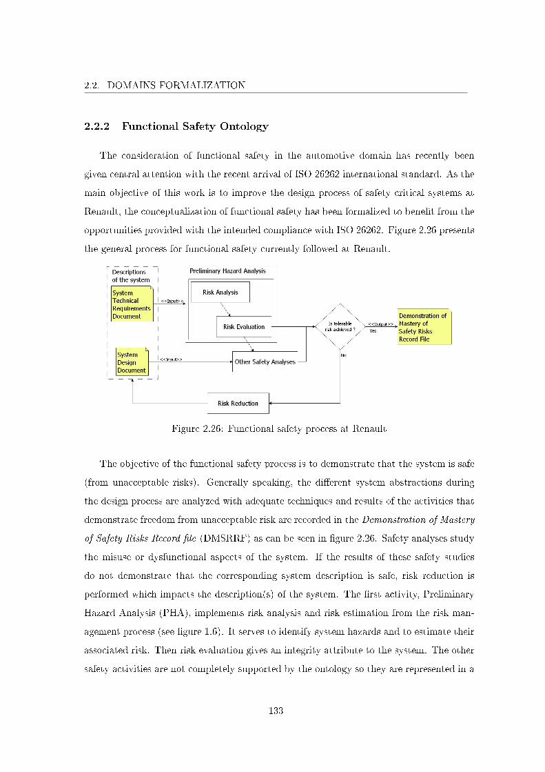
2.2. DOMAINS FORMALIZATION
2.2.2 Functional Safety Ontology
The consideration of functional safety in the automotive domain has recently been
given central attention with the recent arrival of ISO 26262 international standard. As the
main objective of this work is to improve the design process of safety critical systems at
Renault, the conceptualization of functional safety has been formalized to bene�t from the
opportunities provided with the intended compliance with ISO 26262. Figure 2.26 presents
the general process for functional safety currently followed at Renault.
Figure 2.26: Functional safety process at Renault
The objective of the functional safety process is to demonstrate that the system is safe
(from unacceptable risks). Generally speaking, the di�erent system abstractions during
the design process are analyzed with adequate techniques and results of the activities that
demonstrate freedom from unacceptable risk are recorded in the Demonstration of Mastery
of Safety Risks Record �le (DMSRRF) as can be seen in �gure 2.26. Safety analyses study
the misuse or dysfunctional aspects of the system. If the results of these safety studies
do not demonstrate that the corresponding system description is safe, risk reduction is
performed which impacts the description(s) of the system. The �rst activity, Preliminary
Hazard Analysis (PHA), implements risk analysis and risk estimation from the risk man-
agement process (see �gure 1.6). It serves to identify system hazards and to estimate their
associated risk. Then risk evaluation gives an integrity attribute to the system. The other
safety activities are not completely supported by the ontology so they are represented in a
133
2.2. DOMAINS FORMALIZATION
general manner in the �gure. These safety activities implement the overall process of risk
management at �ner grained levels of abstraction. Those activities must bring evidence
that the root causes of potential failures do not impact on the system integrity attribute
demonstrating that the system is safe. Positive results are recorded into the DMSRRF and
negative ones lead to redesign with the risk reduction step. The functional safety ontology
presented in this section has been designed to promote a more systematic execution of this
process with the focus on the fundamental concepts of functional safety domain and the
PHA. Section 2.2.2.1 presents risk analysis with the di�erent system descriptions, their
respective failure models, the identi�cation of hazardous events, the estimation of corre-
sponding risks, and the related fundamental notions of functional safety. Section 2.2.2.2
presents risk evaluation and is devoted to the notion of integrity. Finally, section 2.2.2.3
gives the conclusion to the formalization of functional safety.
2.2.2.1 Risk Analysis
In the overall process of risk management (see �gure 1.6), risk analysis starts with the
de�nition of intended use and reasonably foreseeable misuse of the system. The system
hazards are identi�ed based on this de�nition. Then the system's risk is estimated. This
general process can be applied at di�erent levels of detail. The formalization presented
below captures a conceptualization of this general process and enables to support the
functional safety studies performed during system design process.
System's Descriptions. Functional safety, as its name implies, is interested in the study
of the functional aspects of a system with respect to safety in order to handle functional and
technological issues. These issues are relative to di�erent system's descriptions which are
the responsibility of systems engineering. As such, the STR and the SDD are prerequisites
to functional safety examination as can be seen in �gure 1.6. The ontology therefore
contains similar classes presented in section 2.2.1. Figure 2.27 presents the elements that
correspond to di�erent system descriptions considered by functional safety .
The class Requirement records the system requirements. A safety attribute is de�ned
for the class with property safety_Req that ranges over booleans true and false. It has two
134
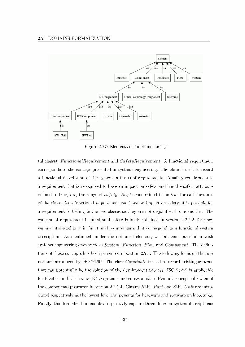
2.2. DOMAINS FORMALIZATION
Figure 2.27: Elements of functional safety
subclasses, FunctionalRequirement and SafetyRequirement. A functional requirement
corresponds to the concept presented in systems engineering. The class is used to record
a functional description of the system in terms of requirements. A safety requirement is
a requirement that is recognized to have an impact on safety and has the safety attribute
de�ned to true, i.e., the range of safety_Req is constrained to be true for each instance
of the class. As a functional requirement can have an impact on safety, it is possible for
a requirement to belong to the two classes so they are not disjoint with one another. The
concept of requirement in functional safety is further de�ned in section 2.2.2.2, for now,
we are interested only in functional requirements that correspond to a functional system
description. As mentioned, under the notion of element, we �nd concepts similar with
systems engineering ones such as System, Function, Flow and Component. The de�ni-
tions of those concepts has been presented in section 2.2.1. The following focus on the new
notions introduced by ISO 26262. The class Candidate is used to record existing systems
that can potentially be the solution of the development process. ISO 26262 is applicable
for Electric and Electronic (E/E) systems and corresponds to Renault conceptualization of
the components presented in section 2.2.1.4. Classes HW_Part and SW_Unit are intro-
duced respectively as the lowest level components for hardware and software architectures.
Finally, this formalization enables to partially capture three di�erent system descriptions:
135
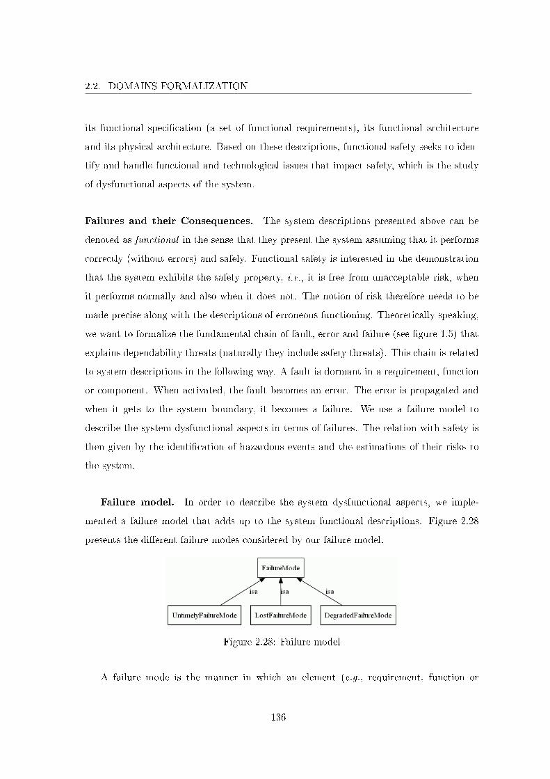
2.2. DOMAINS FORMALIZATION
its functional speci�cation (a set of functional requirements), its functional architecture
and its physical architecture. Based on these descriptions, functional safety seeks to iden-
tify and handle functional and technological issues that impact safety, which is the study
of dysfunctional aspects of the system.
Failures and their Consequences. The system descriptions presented above can be
denoted as functional in the sense that they present the system assuming that it performs
correctly (without errors) and safely. Functional safety is interested in the demonstration
that the system exhibits the safety property, i.e., it is free from unacceptable risk, when
it performs normally and also when it does not. The notion of risk therefore needs to be
made precise along with the descriptions of erroneous functioning. Theoretically speaking,
we want to formalize the fundamental chain of fault, error and failure (see �gure 1.5) that
explains dependability threats (naturally they include safety threats). This chain is related
to system descriptions in the following way. A fault is dormant in a requirement, function
or component. When activated, the fault becomes an error. The error is propagated and
when it gets to the system boundary, it becomes a failure. We use a failure model to
describe the system dysfunctional aspects in terms of failures. The relation with safety is
then given by the identi�cation of hazardous events and the estimations of their risks to
the system.
Failure model. In order to describe the system dysfunctional aspects, we imple-
mented a failure model that adds up to the system functional descriptions. Figure 2.28
presents the di�erent failure modes considered by our failure model.
Figure 2.28: Failure model
A failure mode is the manner in which an element (e.g., requirement, function or
136
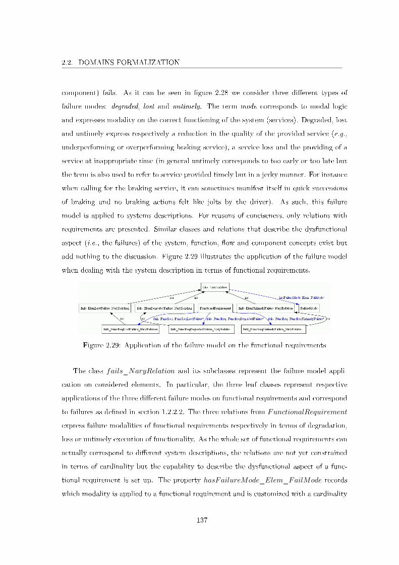
2.2. DOMAINS FORMALIZATION
component) fails. As it can be seen in �gure 2.28 we consider three di�erent types of
failure modes: degraded, lost and untimely. The term mode corresponds to modal logic
and expresses modality on the correct functioning of the system (services). Degraded, lost
and untimely express respectively a reduction in the quality of the provided service (e.g.,
underperforming or overperforming braking service), a service loss and the providing of a
service at inappropriate time (in general untimely corresponds to too early or too late but
the term is also used to refer to service provided timely but in a jerky manner. For instance
when calling for the braking service, it can sometimes manifest itself in quick successions
of braking and no braking actions felt like jolts by the driver). As such, this failure
model is applied to systems descriptions. For reasons of conciseness, only relations with
requirements are presented. Similar classes and relations that describe the dysfunctional
aspect (i.e., the failures) of the system, function, �ow and component concepts exist but
add nothing to the discussion. Figure 2.29 illustrates the application of the failure model
when dealing with the system description in terms of functional requirements.
Figure 2.29: Application of the failure model on the functional requirements
The class fails_NaryRelation and its subclasses represent the failure model appli-
cation on considered elements. In particular, the three leaf classes represent respective
applications of the three di�erent failure modes on functional requirements and correspond
to failures as de�ned in section 1.2.2.2. The three relations from FunctionalRequirement
express failure modalities of functional requirements respectively in terms of degradation,
loss or untimely execution of functionality. As the whole set of functional requirements can
actually correspond to di�erent system descriptions, the relations are not yet constrained
in terms of cardinality but the capability to describe the dysfunctional aspect of a func-
tional requirement is set up. The property hasFailureMode_Elem_FailMode records
which modality is applied to a functional requirement and is customized with a cardinality
137
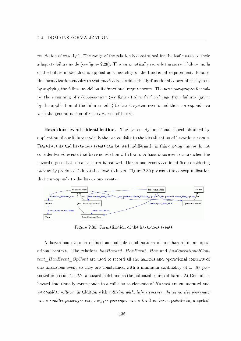
2.2. DOMAINS FORMALIZATION
restriction of exactly 1. The range of the relation is constrained for the leaf classes to their
adequate failure mode (see �gure 2.28). This automatically records the correct failure mode
of the failure model that is applied as a modality of the functional requirement. Finally,
this formalization enables to systematically consider the dysfunctional aspect of the system
by applying the failure model on its functional requirements. The next paragraphs formal-
ize the remaining of risk assessment (see �gure 1.6) with the change from failures (given
by the application of the failure model) to feared system events and their correspondence
with the general notion of risk (i.e., risk of harm).
Hazardous events identi�cation. The system dysfunctional aspect obtained by
application of our failure model is the prerequisite to the identi�cation of hazardous events.
Feared events and hazardous events can be used indi�erently in this ontology as we do not
consider feared events that have no relation with harm. A hazardous event occurs when the
hazard's potential to cause harm is realized. Hazardous events are identi�ed considering
previously produced failures that lead to harm. Figure 2.30 presents the conceptualization
that corresponds to the hazardous events.
Figure 2.30: Formalization of the hazardous events
A hazardous event is de�ned as multiple combinations of one hazard in an oper-
ational context. The relations hasHazard_HazEvent_Haz and hasOperationalCon-
text_HazEvent_OpCont are used to record all the hazards and operational contexts of
one hazardous event so they are constrained with a minimum cardinality of 1. As pre-
sented in section 1.2.2.2, a hazard is de�ned as the potential source of harm. At Renault, a
hazard traditionally corresponds to a collision so elements of Hazard are enumerated and
we consider rollover in addition with collision with, infrastructure, the same size passenger
car, a smaller passenger car, a bigger passenger car, a truck or bus, a pedestrian, a cyclist,
138
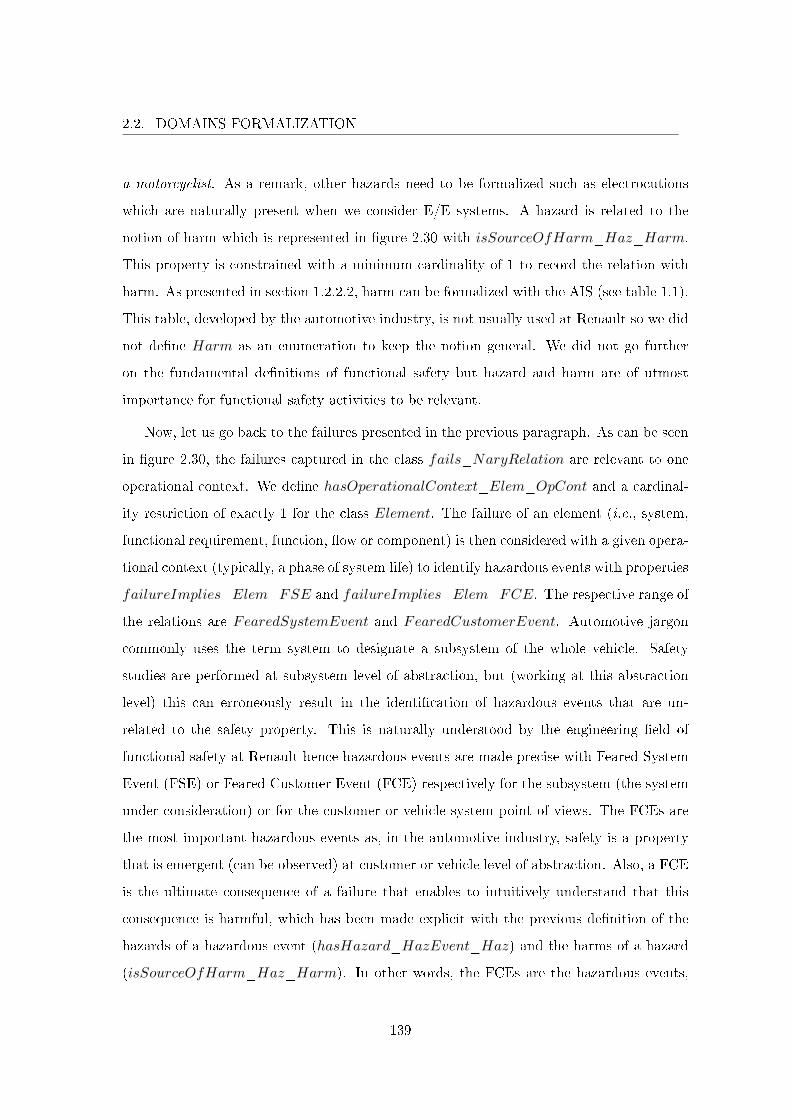
2.2. DOMAINS FORMALIZATION
a motorcyclist. As a remark, other hazards need to be formalized such as electrocutions
which are naturally present when we consider E/E systems. A hazard is related to the
notion of harm which is represented in �gure 2.30 with isSourceOfHarm_Haz_Harm.
This property is constrained with a minimum cardinality of 1 to record the relation with
harm. As presented in section 1.2.2.2, harm can be formalized with the AIS (see table 1.1).
This table, developed by the automotive industry, is not usually used at Renault so we did
not de�ne Harm as an enumeration to keep the notion general. We did not go further
on the fundamental de�nitions of functional safety but hazard and harm are of utmost
importance for functional safety activities to be relevant.
Now, let us go back to the failures presented in the previous paragraph. As can be seen
in �gure 2.30, the failures captured in the class fails_NaryRelation are relevant to one
operational context. We de�ne hasOperationalContext_Elem_OpCont and a cardinal-
ity restriction of exactly 1 for the class Element. The failure of an element (i.e., system,
functional requirement, function, �ow or component) is then considered with a given opera-
tional context (typically, a phase of system life) to identify hazardous events with properties
failureImplies_Elem_FSE and failureImplies_Elem_FCE. The respective range of
the relations are FearedSystemEvent and FearedCustomerEvent. Automotive jargon
commonly uses the term system to designate a subsystem of the whole vehicle. Safety
studies are performed at subsystem level of abstraction, but (working at this abstraction
level) this can erroneously result in the identi�cation of hazardous events that are un-
related to the safety property. This is naturally understood by the engineering �eld of
functional safety at Renault hence hazardous events are made precise with Feared System
Event (FSE) or Feared Customer Event (FCE) respectively for the subsystem (the system
under consideration) or for the customer or vehicle system point of views. The FCEs are
the most important hazardous events as, in the automotive industry, safety is a property
that is emergent (can be observed) at customer or vehicle level of abstraction. Also, a FCE
is the ultimate consequence of a failure that enables to intuitively understand that this
consequence is harmful, which has been made explicit with the previous de�nition of the
hazards of a hazardous event (hasHazard_HazEvent_Haz) and the harms of a hazard
(isSourceOfHarm_Haz_Harm). In other words, the FCEs are the hazardous events,
139
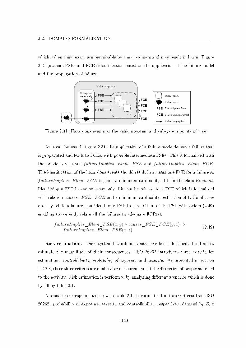
2.2. DOMAINS FORMALIZATION
which, when they occur, are perceivable by the customers and may result in harm. Figure
2.31 presents FSEs and FCEs identi�cation based on the application of the failure model
and the propagation of failures.
Figure 2.31: Hazardous events at the vehicle system and subsystem points of view
As it can be seen in �gure 2.31, the application of a failure mode de�nes a failure that
is propagated and leads to FCEs, with possible intermediate FSEs. This is formalized with
the previous relations failureImplies_Elem_FSE and failureImplies_Elem_FCE.
The identi�cation of the hazardous events should result in at least one FCE for a failure so
failureImplies_Elem_FCE is given a minimum cardinality of 1 for the class Element.
Identifying a FSE has some sense only if it can be related to a FCE which is formalized
with relation causes_FSE_FCE and a minimum cardinality restriction of 1. Finally, we
directly relate a failure that identi�es a FSE to the FCE(s) of the FSE with axiom (2.49)
enabling to correctly relate all the failures to adequate FCE(s).
failureImplies_Elem_FSE(x, y) ∧ causes_FSE_FCE(y, z)⇒failureImplies_Elem_FSE(x, z)
(2.49)
Risk estimation. Once system hazardous events have been identi�ed, it is time to
estimate the magnitude of their consequences. ISO 26262 introduces three criteria for
estimation: controllability, probability of exposure and severity. As presented in section
1.2.2.3, these three criteria are qualitative measurements at the discretion of people assigned
to the activity. Risk estimation is performed by analyzing di�erent scenarios which is done
by �lling table 2.1.
A scenario corresponds to a row in table 2.1. It estimates the three criteria from ISO
26262: probability of exposure, severity and controllability, respectively denoted by E, S
140
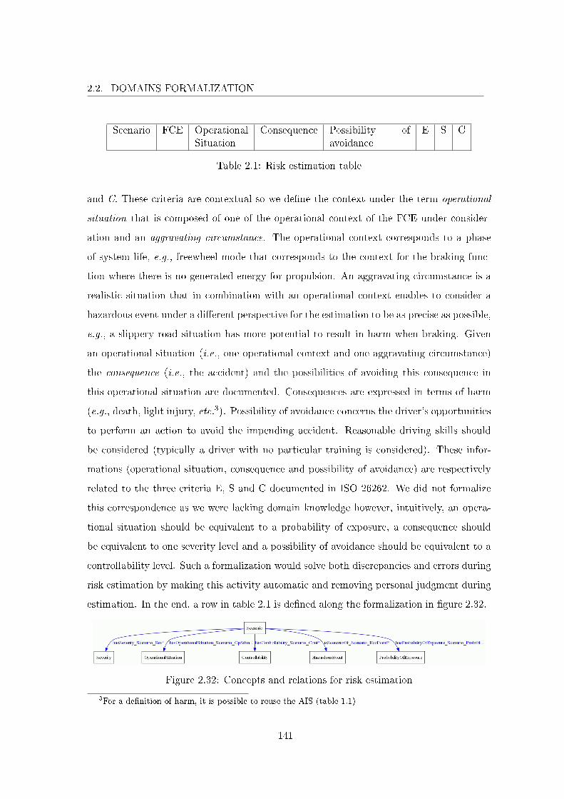
2.2. DOMAINS FORMALIZATION
Scenario FCE OperationalSituation
Consequence Possibility ofavoidance
E S C
Table 2.1: Risk estimation table
and C. These criteria are contextual so we de�ne the context under the term operational
situation that is composed of one of the operational context of the FCE under consider-
ation and an aggravating circumstance. The operational context corresponds to a phase
of system life, e.g., freewheel mode that corresponds to the context for the braking func-
tion where there is no generated energy for propulsion. An aggravating circumstance is a
realistic situation that in combination with an operational context enables to consider a
hazardous event under a di�erent perspective for the estimation to be as precise as possible,
e.g., a slippery road situation has more potential to result in harm when braking. Given
an operational situation (i.e., one operational context and one aggravating circumstance)
the consequence (i.e., the accident) and the possibilities of avoiding this consequence in
this operational situation are documented. Consequences are expressed in terms of harm
(e.g., death, light injury, etc.3). Possibility of avoidance concerns the driver's opportunities
to perform an action to avoid the impending accident. Reasonable driving skills should
be considered (typically a driver with no particular training is considered). These infor-
mations (operational situation, consequence and possibility of avoidance) are respectively
related to the three criteria E, S and C documented in ISO 26262. We did not formalize
this correspondence as we were lacking domain knowledge however, intuitively, an opera-
tional situation should be equivalent to a probability of exposure, a consequence should
be equivalent to one severity level and a possibility of avoidance should be equivalent to a
controllability level. Such a formalization would solve both discrepancies and errors during
risk estimation by making this activity automatic and removing personal judgment during
estimation. In the end, a row in table 2.1 is de�ned along the formalization in �gure 2.32.
Figure 2.32: Concepts and relations for risk estimation
3For a de�nition of harm, it is possible to reuse the AIS (table 1.1)
141
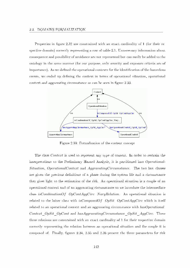
2.2. DOMAINS FORMALIZATION
Properties in �gure 2.32 are constrained with an exact cardinality of 1 (for their re-
spective domain) correctly representing a row of table 2.1. Unnecessary information about
consequence and possibility of avoidance are not represented but can easily be added to the
ontology in the same manner (for our purpose, only severity and exposure criteria are of
importance). As we de�ned the operational contexts for the identi�cation of the hazardous
events, we ended up de�ning the context in terms of operational situation, operational
context and aggravating circumstance as can be seen in �gure 2.33.
Figure 2.33: Formalization of the context concept
The class Context is used to represent any type of context. In order to restrain the
interpretations to the Preliminary Hazard Analysis, it is partitioned into Operational-
Situation, OperationalContext and AggravatingCircumstance. The two last classes
are given the previous de�nitions of a phase during the system life and a circumstance
that gives light to the estimation of the risk. An operational situation is a couple of an
operational context and of an aggravating circumstance so we introduce the intermediate
class isCombinationOf_OpContAggCirc_NaryRelation. An operational situation is
related to the latter class with isComposedOf_OpSit_OpContAggCirc which is itself
related to an operational context and an aggravating circumstance with hasOperational-
Context_OpSit_OpCont and hasAggravatingCircumstance_OpSit_AggCirc. These
three relations are constrained with an exact cardinality of 1 for their respective domain
correctly representing the relation between an operational situation and the couple it is
composed of. Finally, �gures 2.34, 2.35 and 2.36 present the three parameters for risk
142
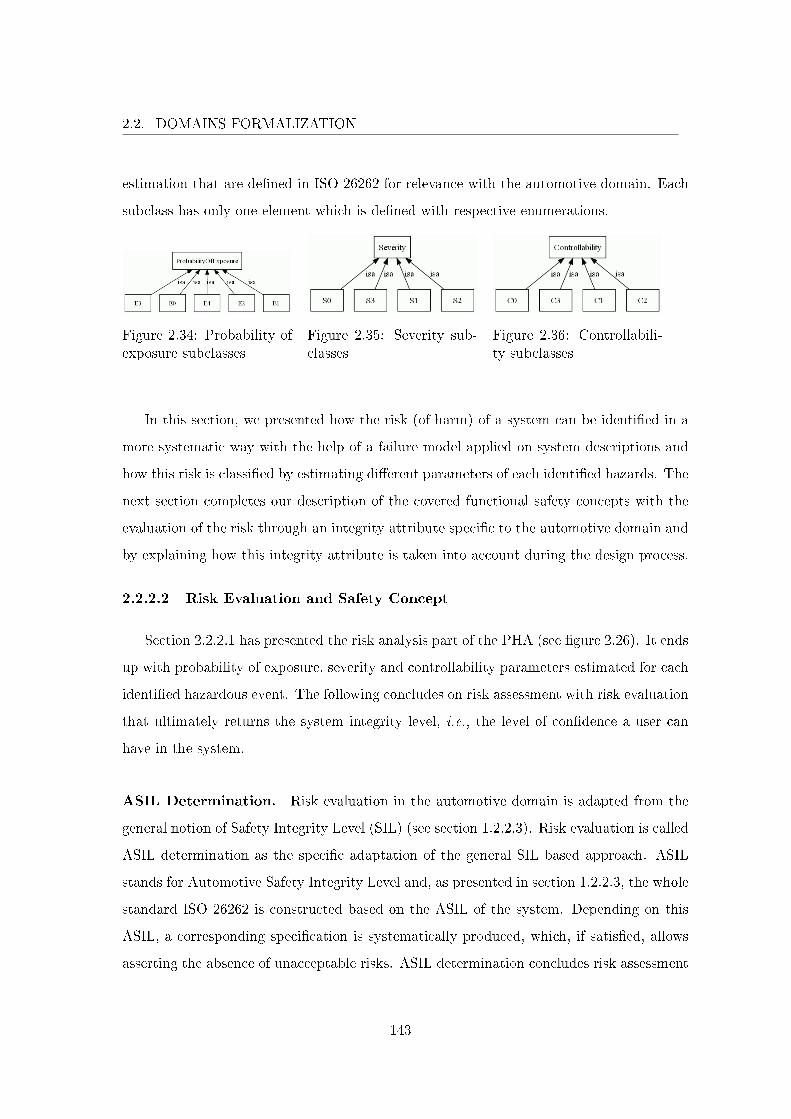
2.2. DOMAINS FORMALIZATION
estimation that are de�ned in ISO 26262 for relevance with the automotive domain. Each
subclass has only one element which is de�ned with respective enumerations.
Figure 2.34: Probability ofexposure subclasses
Figure 2.35: Severity sub-classes
Figure 2.36: Controllabili-ty subclasses
In this section, we presented how the risk (of harm) of a system can be identi�ed in a
more systematic way with the help of a failure model applied on system descriptions and
how this risk is classi�ed by estimating di�erent parameters of each identi�ed hazards. The
next section completes our description of the covered functional safety concepts with the
evaluation of the risk through an integrity attribute speci�c to the automotive domain and
by explaining how this integrity attribute is taken into account during the design process.
2.2.2.2 Risk Evaluation and Safety Concept
Section 2.2.2.1 has presented the risk analysis part of the PHA (see �gure 2.26). It ends
up with probability of exposure, severity and controllability parameters estimated for each
identi�ed hazardous event. The following concludes on risk assessment with risk evaluation
that ultimately returns the system integrity level, i.e., the level of con�dence a user can
have in the system.
ASIL Determination. Risk evaluation in the automotive domain is adapted from the
general notion of Safety Integrity Level (SIL) (see section 1.2.2.3). Risk evaluation is called
ASIL determination as the speci�c adaptation of the general SIL based approach. ASIL
stands for Automotive Safety Integrity Level and, as presented in section 1.2.2.3, the whole
standard ISO 26262 is constructed based on the ASIL of the system. Depending on this
ASIL, a corresponding speci�cation is systematically produced, which, if satis�ed, allows
asserting the absence of unacceptable risks. ASIL determination concludes risk assessment
143

2.2. DOMAINS FORMALIZATION
by completing table 2.1 with an ASIL column �lled by following table 1.4 de�ned in ISO
26262 in chapter 1 reinstated here for reading convenience.
Severity ExposureControllabilityC1 C2 C3
S1
E1 QM QM QME2 QM QM QME3 QM QM AE4 QM A B
S2
E1 QM QM QME2 QM QM AE3 QM A BE4 A B C
S3
E1 QM QM AE2 QM A BE3 A B CE4 B C D
Table 1.4: Automotive Safety Integrity Levels
The class ASIL and its subclasses are de�ned as illustrated in �gure 2.37.
Figure 2.37: ASIL determination
Figure 2.37 presents the concept of ASIL as a scenario attribute. The subclasses of
ASIL de�ne the four di�erent levels de�ned by the standard. They range from A to D
with D being the most restrictive. An ASIL is evaluated for a scenario with property has-
ASILV alue_Scenario_ASIL. This evaluation is systematic and based upon estimated
probability of exposure, severity and controllability criteria during risk estimation as de-
�ned by table 1.4. Each line in the table establishes a direct correspondence between a
triple of the previous parameters for risk estimation and an ASIL. Each line is de�ned with
144
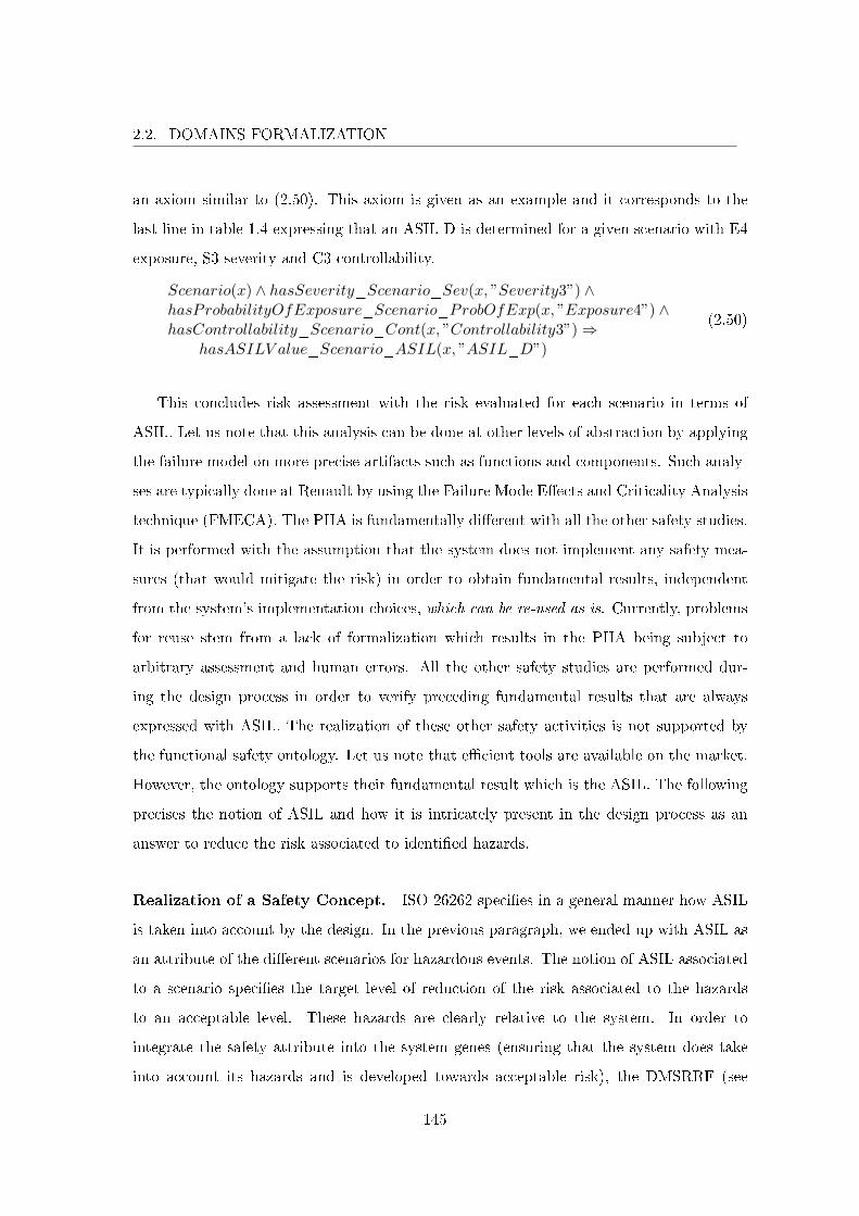
2.2. DOMAINS FORMALIZATION
an axiom similar to (2.50). This axiom is given as an example and it corresponds to the
last line in table 1.4 expressing that an ASIL D is determined for a given scenario with E4
exposure, S3 severity and C3 controllability.
Scenario(x) ∧ hasSeverity_Scenario_Sev(x, ”Severity3”) ∧hasProbabilityOfExposure_Scenario_ProbOfExp(x, ”Exposure4”) ∧hasControllability_Scenario_Cont(x, ”Controllability3”)⇒
hasASILV alue_Scenario_ASIL(x, ”ASIL_D”)
(2.50)
This concludes risk assessment with the risk evaluated for each scenario in terms of
ASIL. Let us note that this analysis can be done at other levels of abstraction by applying
the failure model on more precise artifacts such as functions and components. Such analy-
ses are typically done at Renault by using the Failure Mode E�ects and Criticality Analysis
technique (FMECA). The PHA is fundamentally di�erent with all the other safety studies.
It is performed with the assumption that the system does not implement any safety mea-
sures (that would mitigate the risk) in order to obtain fundamental results, independent
from the system's implementation choices, which can be re-used as is. Currently, problems
for reuse stem from a lack of formalization which results in the PHA being subject to
arbitrary assessment and human errors. All the other safety studies are performed dur-
ing the design process in order to verify preceding fundamental results that are always
expressed with ASIL. The realization of these other safety activities is not supported by
the functional safety ontology. Let us note that e�cient tools are available on the market.
However, the ontology supports their fundamental result which is the ASIL. The following
precises the notion of ASIL and how it is intricately present in the design process as an
answer to reduce the risk associated to identi�ed hazards.
Realization of a Safety Concept. ISO 26262 speci�es in a general manner how ASIL
is taken into account by the design. In the previous paragraph, we ended up with ASIL as
an attribute of the di�erent scenarios for hazardous events. The notion of ASIL associated
to a scenario speci�es the target level of reduction of the risk associated to the hazards
to an acceptable level. These hazards are clearly relative to the system. In order to
integrate the safety attribute into the system genes (ensuring that the system does take
into account its hazards and is developed towards acceptable risk), the DMSRRF (see
145
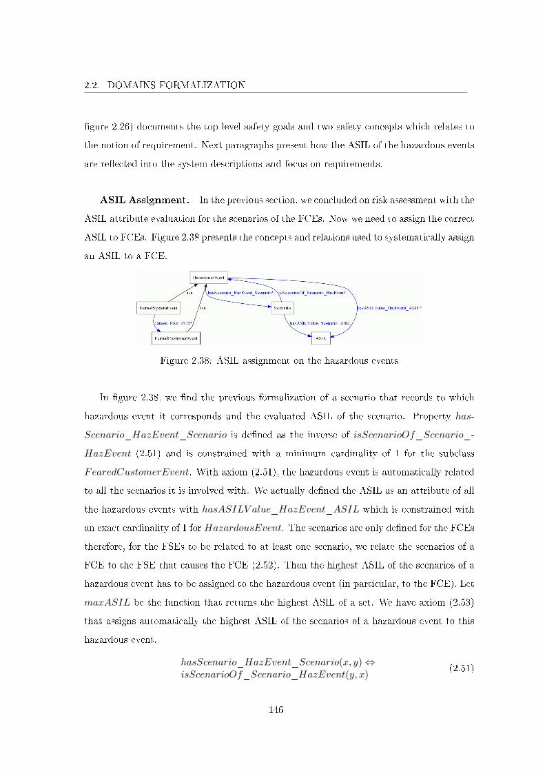
2.2. DOMAINS FORMALIZATION
�gure 2.26) documents the top level safety goals and two safety concepts which relates to
the notion of requirement. Next paragraphs present how the ASIL of the hazardous events
are re�ected into the system descriptions and focus on requirements.
ASIL Assignment. In the previous section, we concluded on risk assessment with the
ASIL attribute evaluation for the scenarios of the FCEs. Now we need to assign the correct
ASIL to FCEs. Figure 2.38 presents the concepts and relations used to systematically assign
an ASIL to a FCE.
Figure 2.38: ASIL assignment on the hazardous events
In �gure 2.38, we �nd the previous formalization of a scenario that records to which
hazardous event it corresponds and the evaluated ASIL of the scenario. Property has-
Scenario_HazEvent_Scenario is de�ned as the inverse of isScenarioOf_Scenario_-
HazEvent (2.51) and is constrained with a minimum cardinality of 1 for the subclass
FearedCustomerEvent. With axiom (2.51), the hazardous event is automatically related
to all the scenarios it is involved with. We actually de�ned the ASIL as an attribute of all
the hazardous events with hasASILV alue_HazEvent_ASIL which is constrained with
an exact cardinality of 1 for HazardousEvent. The scenarios are only de�ned for the FCEs
therefore, for the FSEs to be related to at least one scenario, we relate the scenarios of a
FCE to the FSE that causes the FCE (2.52). Then the highest ASIL of the scenarios of a
hazardous event has to be assigned to the hazardous event (in particular, to the FCE). Let
maxASIL be the function that returns the highest ASIL of a set. We have axiom (2.53)
that assigns automatically the highest ASIL of the scenarios of a hazardous event to this
hazardous event.
hasScenario_HazEvent_Scenario(x, y)⇔isScenarioOf_Scenario_HazEvent(y, x)
(2.51)
146
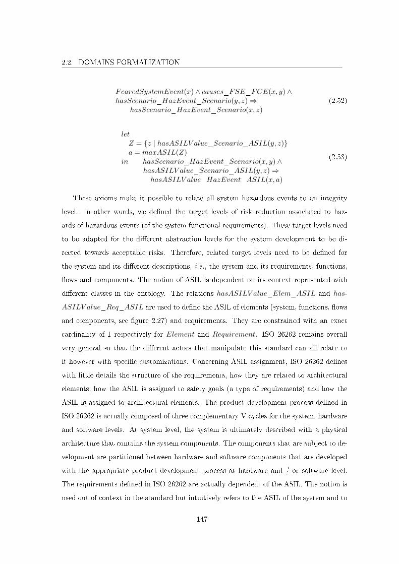
2.2. DOMAINS FORMALIZATION
FearedSystemEvent(x) ∧ causes_FSE_FCE(x, y) ∧hasScenario_HazEvent_Scenario(y, z)⇒
hasScenario_HazEvent_Scenario(x, z)(2.52)
letZ = {z | hasASILV alue_Scenario_ASIL(y, z)}a = maxASIL(Z)
in hasScenario_HazEvent_Scenario(x, y) ∧hasASILV alue_Scenario_ASIL(y, z)⇒hasASILV alue_HazEvent_ASIL(x, a)
(2.53)
These axioms make it possible to relate all system hazardous events to an integrity
level. In other words, we de�ned the target levels of risk reduction associated to haz-
ards of hazardous events (of the system functional requirements). These target levels need
to be adapted for the di�erent abstraction levels for the system development to be di-
rected towards acceptable risks. Therefore, related target levels need to be de�ned for
the system and its di�erent descriptions, i.e., the system and its requirements, functions,
�ows and components. The notion of ASIL is dependent on its context represented with
di�erent classes in the ontology. The relations hasASILV alue_Elem_ASIL and has-
ASILV alue_Req_ASIL are used to de�ne the ASIL of elements (system, functions, �ows
and components, see �gure 2.27) and requirements. They are constrained with an exact
cardinality of 1 respectively for Element and Requirement. ISO 26262 remains overall
very general so that the di�erent actors that manipulate this standard can all relate to
it however with speci�c customizations. Concerning ASIL assignment, ISO 26262 de�nes
with little details the structure of the requirements, how they are related to architectural
elements, how the ASIL is assigned to safety goals (a type of requirements) and how the
ASIL is assigned to architectural elements. The product development process de�ned in
ISO 26262 is actually composed of three complementary V cycles for the system, hardware
and software levels. At system level, the system is ultimately described with a physical
architecture that contains the system components. The components that are subject to de-
velopment are partitioned between hardware and software components that are developed
with the appropriate product development process at hardware and / or software level.
The requirements de�ned in ISO 26262 are actually dependent of the ASIL. The notion is
used out of context in the standard but intuitively refers to the ASIL of the system and to
147
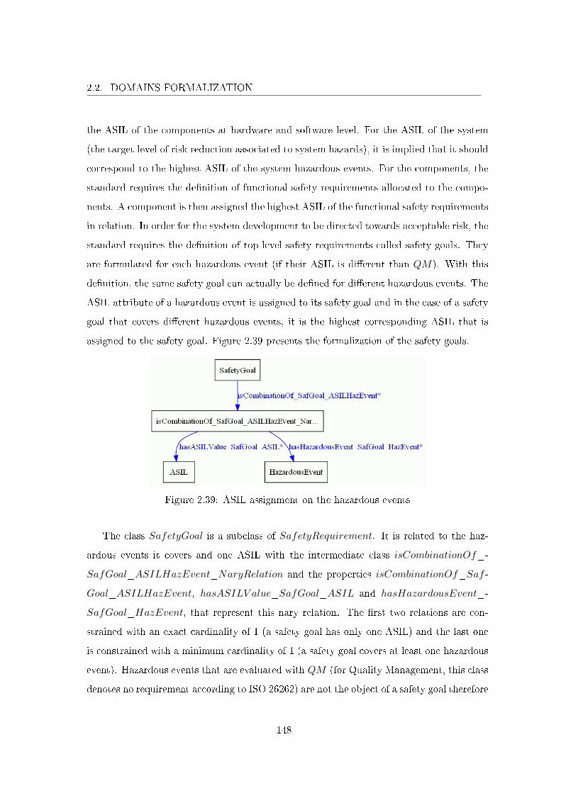
2.2. DOMAINS FORMALIZATION
the ASIL of the components at hardware and software level. For the ASIL of the system
(the target level of risk reduction associated to system hazards), it is implied that it should
correspond to the highest ASIL of the system hazardous events. For the components, the
standard requires the de�nition of functional safety requirements allocated to the compo-
nents. A component is then assigned the highest ASIL of the functional safety requirements
in relation. In order for the system development to be directed towards acceptable risk, the
standard requires the de�nition of top level safety requirements called safety goals. They
are formulated for each hazardous event (if their ASIL is di�erent than QM). With this
de�nition, the same safety goal can actually be de�ned for di�erent hazardous events. The
ASIL attribute of a hazardous event is assigned to its safety goal and in the case of a safety
goal that covers di�erent hazardous events, it is the highest corresponding ASIL that is
assigned to the safety goal. Figure 2.39 presents the formalization of the safety goals.
Figure 2.39: ASIL assignment on the hazardous events
The class SafetyGoal is a subclass of SafetyRequirement. It is related to the haz-
ardous events it covers and one ASIL with the intermediate class isCombinationOf_-
SafGoal_ASILHazEvent_NaryRelation and the properties isCombinationOf_Saf -
Goal_ASILHazEvent, hasASILV alue_SafGoal_ASIL and hasHazardousEvent_-
SafGoal_HazEvent, that represent this nary relation. The �rst two relations are con-
strained with an exact cardinality of 1 (a safety goal has only one ASIL) and the last one
is constrained with a minimum cardinality of 1 (a safety goal covers at least one hazardous
event). Hazardous events that are evaluated with QM (for Quality Management, this class
denotes no requirement according to ISO 26262) are not the object of a safety goal therefore
148
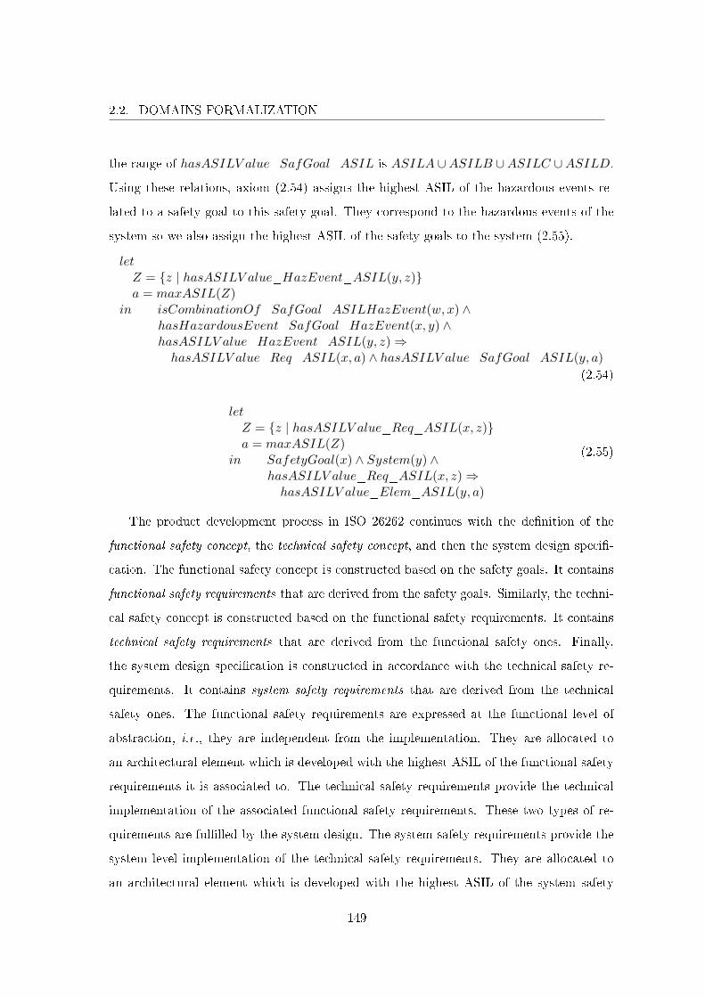
2.2. DOMAINS FORMALIZATION
the range of hasASILV alue_SafGoal_ASIL is ASILA ∪ASILB ∪ASILC ∪ASILD.
Using these relations, axiom (2.54) assigns the highest ASIL of the hazardous events re-
lated to a safety goal to this safety goal. They correspond to the hazardous events of the
system so we also assign the highest ASIL of the safety goals to the system (2.55).
letZ = {z | hasASILV alue_HazEvent_ASIL(y, z)}a = maxASIL(Z)
in isCombinationOf_SafGoal_ASILHazEvent(w, x) ∧hasHazardousEvent_SafGoal_HazEvent(x, y) ∧hasASILV alue_HazEvent_ASIL(y, z)⇒hasASILV alue_Req_ASIL(x, a) ∧ hasASILV alue_SafGoal_ASIL(y, a)
(2.54)
letZ = {z | hasASILV alue_Req_ASIL(x, z)}a = maxASIL(Z)
in SafetyGoal(x) ∧ System(y) ∧hasASILV alue_Req_ASIL(x, z)⇒hasASILV alue_Elem_ASIL(y, a)
(2.55)
The product development process in ISO 26262 continues with the de�nition of the
functional safety concept, the technical safety concept, and then the system design speci�-
cation. The functional safety concept is constructed based on the safety goals. It contains
functional safety requirements that are derived from the safety goals. Similarly, the techni-
cal safety concept is constructed based on the functional safety requirements. It contains
technical safety requirements that are derived from the functional safety ones. Finally,
the system design speci�cation is constructed in accordance with the technical safety re-
quirements. It contains system safety requirements that are derived from the technical
safety ones. The functional safety requirements are expressed at the functional level of
abstraction, i.e., they are independent from the implementation. They are allocated to
an architectural element which is developed with the highest ASIL of the functional safety
requirements it is associated to. The technical safety requirements provide the technical
implementation of the associated functional safety requirements. These two types of re-
quirements are ful�lled by the system design. The system safety requirements provide the
system level implementation of the technical safety requirements. They are allocated to
an architectural element which is developed with the highest ASIL of the system safety
149
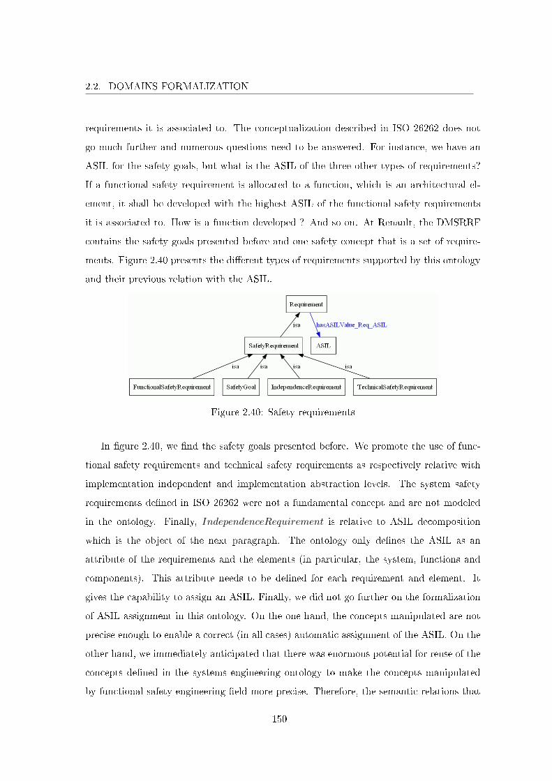
2.2. DOMAINS FORMALIZATION
requirements it is associated to. The conceptualization described in ISO 26262 does not
go much further and numerous questions need to be answered. For instance, we have an
ASIL for the safety goals, but what is the ASIL of the three other types of requirements?
If a functional safety requirement is allocated to a function, which is an architectural el-
ement, it shall be developed with the highest ASIL of the functional safety requirements
it is associated to. How is a function developed ? And so on. At Renault, the DMSRRF
contains the safety goals presented before and one safety concept that is a set of require-
ments. Figure 2.40 presents the di�erent types of requirements supported by this ontology
and their previous relation with the ASIL.
Figure 2.40: Safety requirements
In �gure 2.40, we �nd the safety goals presented before. We promote the use of func-
tional safety requirements and technical safety requirements as respectively relative with
implementation independent and implementation abstraction levels. The system safety
requirements de�ned in ISO 26262 were not a fundamental concept and are not modeled
in the ontology. Finally, IndependenceRequirement is relative to ASIL decomposition
which is the object of the next paragraph. The ontology only de�nes the ASIL as an
attribute of the requirements and the elements (in particular, the system, functions and
components). This attribute needs to be de�ned for each requirement and element. It
gives the capability to assign an ASIL. Finally, we did not go further on the formalization
of ASIL assignment in this ontology. On the one hand, the concepts manipulated are not
precise enough to enable a correct (in all cases) automatic assignment of the ASIL. On the
other hand, we immediately anticipated that there was enormous potential for reuse of the
concepts de�ned in the systems engineering ontology to make the concepts manipulated
by functional safety engineering �eld more precise. Therefore, the semantic relations that
150
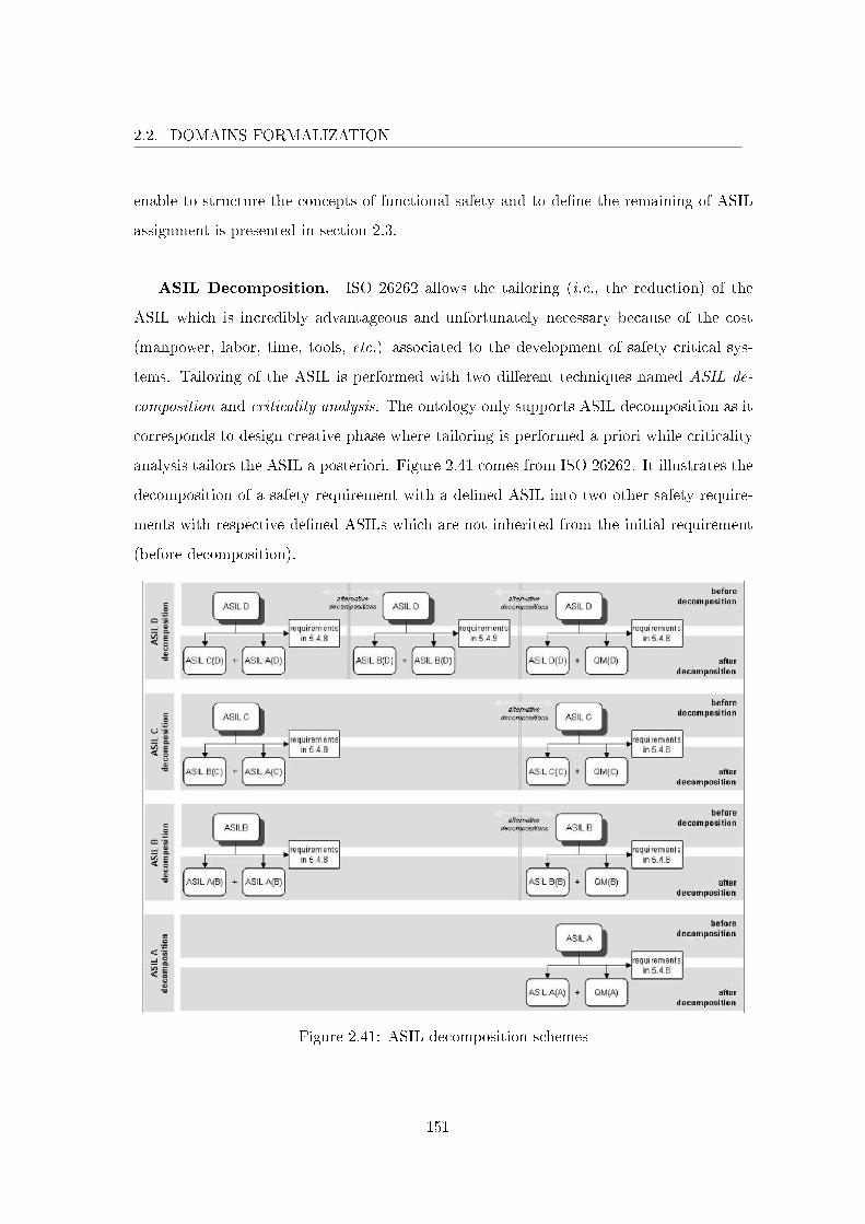
2.2. DOMAINS FORMALIZATION
enable to structure the concepts of functional safety and to de�ne the remaining of ASIL
assignment is presented in section 2.3.
ASIL Decomposition. ISO 26262 allows the tailoring (i.e., the reduction) of the
ASIL which is incredibly advantageous and unfortunately necessary because of the cost
(manpower, labor, time, tools, etc.) associated to the development of safety critical sys-
tems. Tailoring of the ASIL is performed with two di�erent techniques named ASIL de-
composition and criticality analysis. The ontology only supports ASIL decomposition as it
corresponds to design creative phase where tailoring is performed a priori while criticality
analysis tailors the ASIL a posteriori. Figure 2.41 comes from ISO 26262. It illustrates the
decomposition of a safety requirement with a de�ned ASIL into two other safety require-
ments with respective de�ned ASILs which are not inherited from the initial requirement
(before decomposition).
Figure 2.41: ASIL decomposition schemes
151
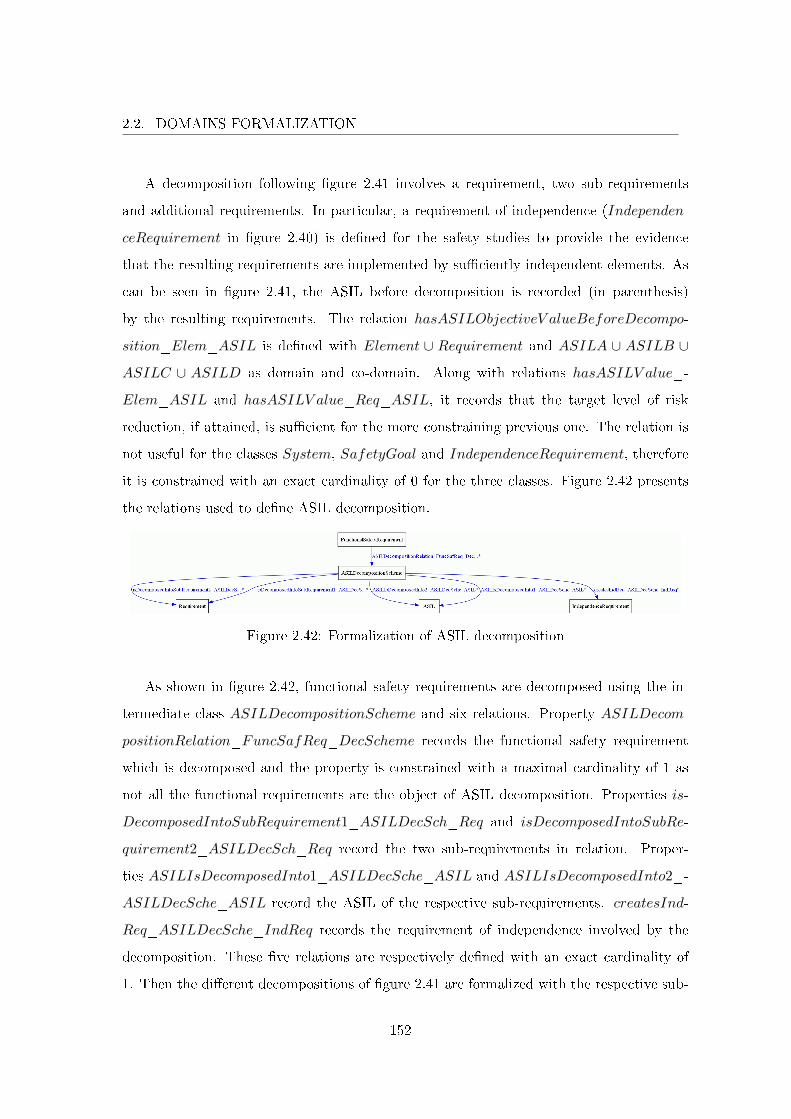
2.2. DOMAINS FORMALIZATION
A decomposition following �gure 2.41 involves a requirement, two sub-requirements
and additional requirements. In particular, a requirement of independence (Independen-
ceRequirement in �gure 2.40) is de�ned for the safety studies to provide the evidence
that the resulting requirements are implemented by su�ciently independent elements. As
can be seen in �gure 2.41, the ASIL before decomposition is recorded (in parenthesis)
by the resulting requirements. The relation hasASILObjectiveV alueBeforeDecompo-
sition_Elem_ASIL is de�ned with Element ∪ Requirement and ASILA ∪ ASILB ∪
ASILC ∪ ASILD as domain and co-domain. Along with relations hasASILV alue_-
Elem_ASIL and hasASILV alue_Req_ASIL, it records that the target level of risk
reduction, if attained, is su�cient for the more constraining previous one. The relation is
not useful for the classes System, SafetyGoal and IndependenceRequirement, therefore
it is constrained with an exact cardinality of 0 for the three classes. Figure 2.42 presents
the relations used to de�ne ASIL decomposition.
Figure 2.42: Formalization of ASIL decomposition
As shown in �gure 2.42, functional safety requirements are decomposed using the in-
termediate class ASILDecompositionScheme and six relations. Property ASILDecom-
positionRelation_FuncSafReq_DecScheme records the functional safety requirement
which is decomposed and the property is constrained with a maximal cardinality of 1 as
not all the functional requirements are the object of ASIL decomposition. Properties is-
DecomposedIntoSubRequirement1_ASILDecSch_Req and isDecomposedIntoSubRe-
quirement2_ASILDecSch_Req record the two sub-requirements in relation. Proper-
ties ASILIsDecomposedInto1_ASILDecSche_ASIL and ASILIsDecomposedInto2_-
ASILDecSche_ASIL record the ASIL of the respective sub-requirements. createsInd-
Req_ASILDecSche_IndReq records the requirement of independence involved by the
decomposition. These �ve relations are respectively de�ned with an exact cardinality of
1. Then the di�erent decompositions of �gure 2.41 are formalized with the respective sub-
152
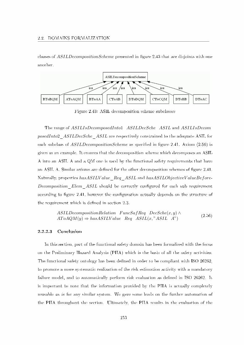
2.2. DOMAINS FORMALIZATION
classes of ASILDecompositionScheme presented in �gure 2.43 that are disjoints with one
another.
Figure 2.43: ASIL decomposition scheme subclasses
The range of ASILIsDecomposedInto1_ASILDecSche_ASIL and ASILIsDecom-
posedInto2_ASILDecSche_ASIL are respectively constrained to the adequate ASIL for
each subclass of ASILDecompositionScheme as speci�ed in �gure 2.41. Axiom (2.56) is
given as an example. It ensures that the decomposition scheme which decomposes an ASIL
A into an ASIL A and a QM one is used by the functional safety requirements that have
an ASIL A. Similar axioms are de�ned for the other decomposition schemes of �gure 2.41.
Naturally, properties hasASILV alue_Req_ASIL and hasASILObjectiveV alueBefore-
Decomposition_Elem_ASIL should be correctly con�gured for each sub requirement
according to �gure 2.41, however the con�guration actually depends on the structure of
the requirement which is de�ned in section 2.3.
ASILDecompositionRelation_FuncSafReq_DecSche(x, y) ∧AToAQM(y)⇒ hasASILV alue_Req_ASIL(x, ”ASIL_A”)
(2.56)
2.2.2.3 Conclusion
In this section, part of the functional safety domain has been formalized with the focus
on the Preliminary Hazard Analysis (PHA) which is the basis of all the safety activities.
The functional safety ontology has been de�ned in order to be compliant with ISO 26262,
to promote a more systematic realization of the risk estimation activity with a mandatory
failure model, and to automatically perform risk evaluation as de�ned in ISO 26262. It
is important to note that the information provided by the PHA is actually completely
reusable as is for any similar system. We gave some leads on the further automation of
the PHA throughout the section. Ultimately, the PHA results in the evaluation of the
153

2.2. DOMAINS FORMALIZATION
ASIL relative to each system hazard. We ended setting the ontology up to support the
assignment of the ASIL on the system, its requirements, its functions and its components.
For reasons of unresolved ambiguities that correspond to licit incompatible interpretations,
the assignment of the ASIL remains manual. One objective of the realization of a domain
ontology is obviously to remove as much as possible these problems of ambiguity. This
removal has been actually purposely deferred to section 2.3 that takes advantage of the two
domain ontologies of systems engineering and functional safety to improve the preciseness
of their concepts which mutually reinforce one another.
2.2.3 Conclusion
Sections 2.2.1 and 2.2.2 present the respective formalizations of the systems engineer-
ing and functional safety domains into ontologies. These formal ontologies de�ne in a
formal way the concepts manipulated by the two engineering �elds and how those concepts
are related to one another. The formal syntax and semantics of the language enables to
automatically de�ne consistency as the property that the asserted axioms are non contra-
dictory. Computer treatment enables to verify the ontologies consistency answering either
if the ontology is consistent or not. In case of inconsistency, the contradiction(s) are pre-
sented. The information that aims to be recorded in our ontologies bene�ts implicitly from
this consistent structure. Abiding with the structure is equivalent for the information to
have correct structure (i.e., the ontology at conceptual and information level is consistent),
ensuring quality. These ontologies are the carrier of structured knowledge. As the semantic
aspect of formal ontologies ensures that the structure of the concepts is understood in a
unique manner, the two ontologies bring together the understanding of the domains at
the conceptual level with the information that needs to be understood at this conceptual
level. In the case that the information is susceptible for reuse, it will be done with correct
understanding. For instance, reusing a component comes with all the functions it realizes.
In the end, these two ontologies correspond to two sides of the development process of
one single system. We concluded on systems engineering as the orchestrator of the other
engineering �elds that contribute to the development. Systems engineering contains the
di�erent system descriptions. The other engineering �elds study the system based on these
154
2.3. GLOBAL DOMAIN FORMALIZATION
descriptions. In particular, functional safety is responsible for assigning an ASIL to all the
elements of systems engineering and demonstrating the absence of unacceptable residual
risks. Also, the results provided by functional safety engineers guide the design of the
system. As such, communication between these two engineering �elds is of the utmost
importance. Section 2.3 presents the integration of these two domains into a domain
ontology for systems and functional safety engineers that enables precise communication
based on this shared conceptualization.
2.3 Global Domain Formalization
SE deployment and the increased concern to comply with ISO 26262 standard have
acted as a catalyst for developing synergies. Renault engineers from di�erent �elds, aca-
demics and other companies sta� have been drawn together to work on these subjects.
At the most basic level, the need to share meaning on terms arises as barriers such as
dissimilar vocabularies, representations or languages can imped those synergies. This can
be answered by de�ning an ontology. It is a formal, explicit speci�cation of a shared con-
ceptualization [Studer et al. 1998] pertaining to a domain. Our ontology is constituted
by a speci�c vocabulary of terms used in the domain with an explicit speci�cation of their
meaning, i.e., de�nition of the concepts of the domain and their relationships. It de�nes
a structure of the domain and constrains the possible interpretations of terms. Informally,
an ontology enables a precise and non ambiguous communication as everybody shares the
same language. This section addresses the integration of the two domain ontologies pre-
sented in section 2.2.1 and 2.2.2 into a domain ontology that supports the design process
for both systems and functional safety engineers. The intent is to involve the functional
safety engineers in the design process as soon and as much as possible. Actually, other
engineering �elds also impact system design but we support the value that nothing is more
important than safety. Section 2.3.1 presents the concepts integration concepts and focuses
mainly on the requirements which remained ambiguous. Section 2.3.2 concludes on ASIL
assignment. Finally, section 2.3.3 gives the conclusion on the formalization of systems en-
gineering and functional safety. The interested reader may also consult the ontology at the
following address: http://cedric.cnam.fr/~taofif_o/.
155
2.3. GLOBAL DOMAIN FORMALIZATION
2.3.1 Systems Engineering and Functional Safety Domains Integration
The conceptualization of systems engineering and functional safety has been formal-
ized in sections 2.2.1 and 2.2.2. These two domain ontologies enable system engineers and
functional safety engineers to communicate using a de�ned structured vocabulary of terms.
These engineers are involved in the design process of safety critical mechatronics systems
with processes that correspond to each respective �eld presented in �gures 2.1 and 2.26. In
particular, these two engineering �elds manipulate some concepts that are similar, however
with a di�erent focus and conceptualization. These di�erent conceptualizations are trans-
lated in loss of knowledge at the processes interfaces which impeds communication between
the two domains. The systems engineering and functional safety ontology presented in this
section provides the two domains with a common semantic model where concepts ambigu-
ities are resolved enabling correct communication. Section 2.3.1.1 presents the integration
of the systems engineering and functional safety ontologies into a single domain ontology
for systems and functional safety engineers. Section 2.3.1.2 addresses integration at the
information level of detail.
2.3.1.1 Conceptual Integration
OWL is equipped with an importation mechanism that enables to manipulate di�erent
ontologies into the same universe of discourse. The systems engineering and functional
safety ontologies are imported into a single ontology named systems engineering and func-
tional safety ontology. Their importation results in the attribution of di�erent unique
namespaces that precede each identi�ers. Here, p1: and p2: correspond respectively to the
namespaces of systems engineering and functional safety. For instance, p1:Requirement
corresponds to the class in the systems engineering ontology while p2:Requirement is used
for the class in the functional safety ontology. In the resulting ontology, it is now possible
to use any term from the previous ontologies inside the same universe of discourse. The
remaining work is the formalization of a conceptualization which is simply to de�ne more
axioms (i.e., classes, properties and constraints). One di�culty when de�ning an ontol-
ogy lies in the fact that the formalized conceptualization comes from a consensus between
di�erent actors that agree upon, and therefore share, the ontology. When integrating two
156
2.3. GLOBAL DOMAIN FORMALIZATION
ontologies, the di�culty is at the next level. A consensus involves more people and therefore
is more di�cult to attain. Also, the de�ned conceptualizations can be incompatible which
forces to rework those ontologies to enable their integration. In the end the ontologies of
systems engineering and functional safety that have been presented correspond to the �nal
domains conceptualization where incompatibilities have been removed. The integration of
these two ontologies addresses the resolution of concepts ambiguities that remain.
The concepts that are at the interface of systems engineering and functional safety
correspond to system descriptions (architectures). The di�cult part corresponds to the
requirements which is left to the end. The system, functions, �ows and components are
similar / equivalent concepts in the two ontologies. To express this equivalence between
two classes we use set equivalence (symbolized by ≡). The sets A and B are equivalent
(A ≡ B) means that A ⊆ B and A ⊇ B. In terms of classes, classes A and B are equivalent
(A ≡ B) means that A is a subclass of B and B is a subclass of A. Then, according to the
axiomatization given in appendix A, the properties and constraints de�ned for a class are
semantically de�ned for the equivalent class, and the subclasses of a class that is equivalent
to another class semantically inherit all the properties of the two equivalent classes. For
the concepts of system, function, �ow and component we have the following equivalences:
p1 : System ≡ p2 : Systemp1 : Function ≡ p2 : Functionp1 : Flow ≡ p2 : Flowp1 : Component ≡ p2 : Componentp1 : Interface ≡ p2 : Interfacep1 : EEComponent ≡ p2 : EEComponentp1 : Actuator ≡ p2 : Actuatorp1 : Controller ≡ p2 : Controllerp1 : Sensor ≡ p2 : Sensorp1 : HWComponent ≡ p2 : HWComponentp1 : SWComponent ≡ p2 : SWComponentp1 : OtherComponent ≡ p2 : OtherTechnologyComponent
In order to bene�t from the de�nitions provided by the two ontologies for systems
engineering and functional safety, we anticipated the reuse of relations that should have
their similar counterpart in the other ontology, which is why those counterparts are not
de�ned. The integration of the preceding concepts pose no particular di�culty as we did
not detect any incompatibility. The properties and constraints are de�ned correctly for
157
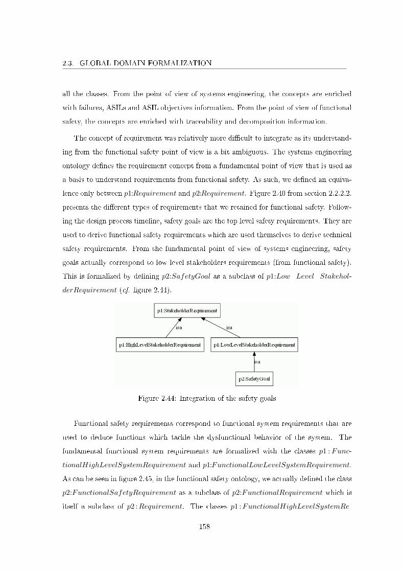
2.3. GLOBAL DOMAIN FORMALIZATION
all the classes. From the point of view of systems engineering, the concepts are enriched
with failures, ASILs and ASIL objectives information. From the point of view of functional
safety, the concepts are enriched with traceability and decomposition information.
The concept of requirement was relatively more di�cult to integrate as its understand-
ing from the functional safety point of view is a bit ambiguous. The systems engineering
ontology de�nes the requirement concept from a fundamental point of view that is used as
a basis to understand requirements from functional safety. As such, we de�ned an equiva-
lence only between p1:Requirement and p2:Requirement. Figure 2.40 from section 2.2.2.2,
presents the di�erent types of requirements that we retained for functional safety. Follow-
ing the design process timeline, safety goals are the top level safety requirements. They are
used to derive functional safety requirements which are used themselves to derive technical
safety requirements. From the fundamental point of view of systems engineering, safety
goals actually correspond to low level stakeholders requirements (from functional safety).
This is formalized by de�ning p2:SafetyGoal as a subclass of p1:Low_Level_Stakehol-
derRequirement (cf. �gure 2.44).
Figure 2.44: Integration of the safety goals
Functional safety requirements correspond to functional system requirements that are
used to deduce functions which tackle the dysfunctional behavior of the system. The
fundamental functional system requirements are formalized with the classes p1 : Func-
tionalHighLevelSystemRequirement and p1:FunctionalLowLevelSystemRequirement.
As can be seen in �gure 2.45, in the functional safety ontology, we actually de�ned the class
p2:FunctionalSafetyRequirement as a subclass of p2:FunctionalRequirement which is
itself a subclass of p2 :Requirement. The classes p1 :FunctionalHighLevelSystemRe-
158
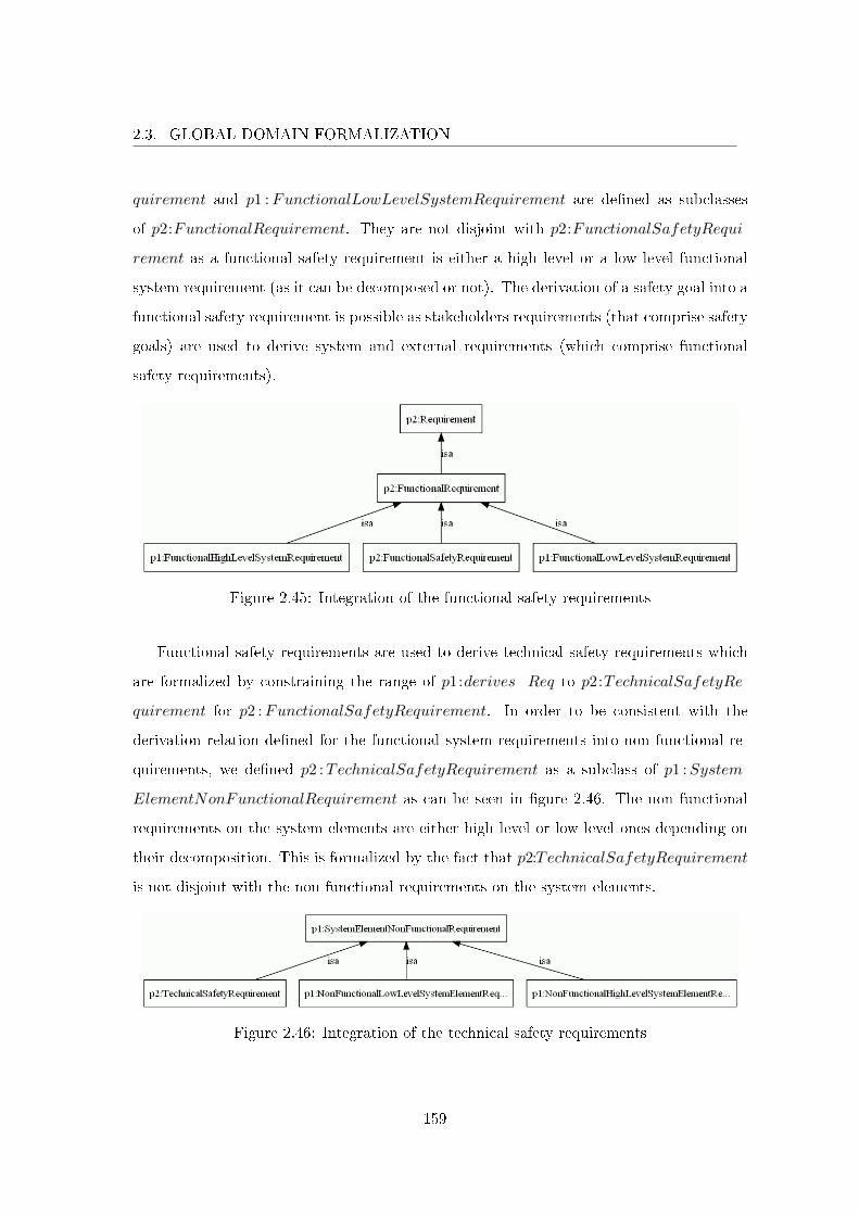
2.3. GLOBAL DOMAIN FORMALIZATION
quirement and p1 :FunctionalLowLevelSystemRequirement are de�ned as subclasses
of p2:FunctionalRequirement. They are not disjoint with p2:FunctionalSafetyRequi-
rement as a functional safety requirement is either a high level or a low level functional
system requirement (as it can be decomposed or not). The derivation of a safety goal into a
functional safety requirement is possible as stakeholders requirements (that comprise safety
goals) are used to derive system and external requirements (which comprise functional
safety requirements).
Figure 2.45: Integration of the functional safety requirements
Functional safety requirements are used to derive technical safety requirements which
are formalized by constraining the range of p1:derives_Req to p2:TechnicalSafetyRe-
quirement for p2 :FunctionalSafetyRequirement. In order to be consistent with the
derivation relation de�ned for the functional system requirements into non functional re-
quirements, we de�ned p2 :TechnicalSafetyRequirement as a subclass of p1 :System-
ElementNonFunctionalRequirement as can be seen in �gure 2.46. The non functional
requirements on the system elements are either high level or low level ones depending on
their decomposition. This is formalized by the fact that p2:TechnicalSafetyRequirement
is not disjoint with the non functional requirements on the system elements.
Figure 2.46: Integration of the technical safety requirements
159
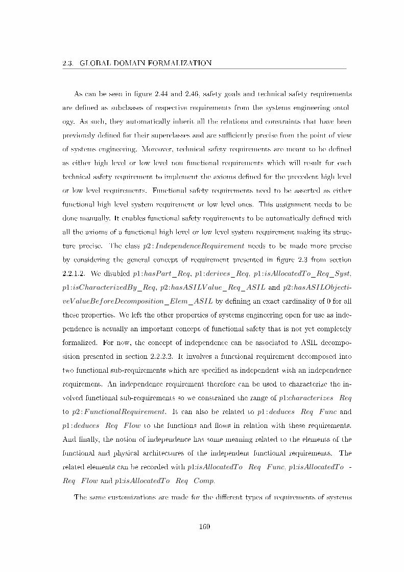
2.3. GLOBAL DOMAIN FORMALIZATION
As can be seen in �gure 2.44 and 2.46, safety goals and technical safety requirements
are de�ned as subclasses of respective requirements from the systems engineering ontol-
ogy. As such, they automatically inherit all the relations and constraints that have been
previously de�ned for their superclasses and are su�ciently precise from the point of view
of systems engineering. Moreover, technical safety requirements are meant to be de�ned
as either high level or low level non functional requirements which will result for each
technical safety requirement to implement the axioms de�ned for the precedent high level
or low level requirements. Functional safety requirements need to be asserted as either
functional high level system requirement or low level ones. This assignment needs to be
done manually. It enables functional safety requirements to be automatically de�ned with
all the axioms of a functional high level or low level system requirement making its struc-
ture precise. The class p2 : IndependenceRequirement needs to be made more precise
by considering the general concept of requirement presented in �gure 2.3 from section
2.2.1.2. We disabled p1:hasPart_Req, p1:derives_Req, p1:isAllocatedTo_Req_Syst,
p1:isCharacterizedBy_Req, p2:hasASILV alue_Req_ASIL and p2:hasASILObjecti-
veV alueBeforeDecomposition_Elem_ASIL by de�ning an exact cardinality of 0 for all
these properties. We left the other properties of systems engineering open for use as inde-
pendence is actually an important concept of functional safety that is not yet completely
formalized. For now, the concept of independence can be associated to ASIL decompo-
sition presented in section 2.2.2.2. It involves a functional requirement decomposed into
two functional sub-requirements which are speci�ed as independent with an independence
requirement. An independence requirement therefore can be used to characterize the in-
volved functional sub-requirements so we constrained the range of p1:characterizes_Req
to p2 :FunctionalRequirement. It can also be related to p1 :deduces_Req_Func and
p1 :deduces_Req_Flow to the functions and �ows in relation with these requirements.
And �nally, the notion of independence has some meaning related to the elements of the
functional and physical architectures of the independent functional requirements. The
related elements can be recorded with p1:isAllocatedTo_Req_Func, p1:isAllocatedTo_-
Req_Flow and p1:isAllocatedTo_Req_Comp.
The same customizations are made for the di�erent types of requirements of systems
160
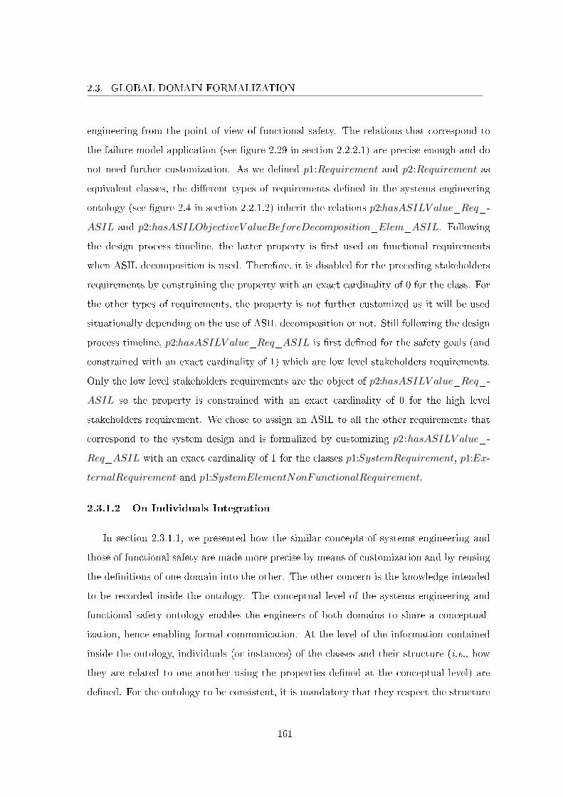
2.3. GLOBAL DOMAIN FORMALIZATION
engineering from the point of view of functional safety. The relations that correspond to
the failure model application (see �gure 2.29 in section 2.2.2.1) are precise enough and do
not need further customization. As we de�ned p1:Requirement and p2:Requirement as
equivalent classes, the di�erent types of requirements de�ned in the systems engineering
ontology (see �gure 2.4 in section 2.2.1.2) inherit the relations p2:hasASILV alue_Req_-
ASIL and p2:hasASILObjectiveV alueBeforeDecomposition_Elem_ASIL. Following
the design process timeline, the latter property is �rst used on functional requirements
when ASIL decomposition is used. Therefore, it is disabled for the preceding stakeholders
requirements by constraining the property with an exact cardinality of 0 for the class. For
the other types of requirements, the property is not further customized as it will be used
situationally depending on the use of ASIL decomposition or not. Still following the design
process timeline, p2:hasASILV alue_Req_ASIL is �rst de�ned for the safety goals (and
constrained with an exact cardinality of 1) which are low level stakeholders requirements.
Only the low level stakeholders requirements are the object of p2:hasASILV alue_Req_-
ASIL so the property is constrained with an exact cardinality of 0 for the high level
stakeholders requirement. We chose to assign an ASIL to all the other requirements that
correspond to the system design and is formalized by customizing p2:hasASILV alue_-
Req_ASIL with an exact cardinality of 1 for the classes p1:SystemRequirement, p1:Ex-
ternalRequirement and p1:SystemElementNonFunctionalRequirement.
2.3.1.2 On Individuals Integration
In section 2.3.1.1, we presented how the similar concepts of systems engineering and
those of functional safety are made more precise by means of customization and by reusing
the de�nitions of one domain into the other. The other concern is the knowledge intended
to be recorded inside the ontology. The conceptual level of the systems engineering and
functional safety ontology enables the engineers of both domains to share a conceptual-
ization, hence enabling formal communication. At the level of the information contained
inside the ontology, individuals (or instances) of the classes and their structure (i.e., how
they are related to one another using the properties de�ned at the conceptual level) are
de�ned. For the ontology to be consistent, it is mandatory that they respect the structure
161
2.3. GLOBAL DOMAIN FORMALIZATION
de�ned at the conceptual level. This section discusses the expressiveness at the individuals
level of granularity and the integration of individuals with the focus on the satisfaction of
cardinality constraints.
Integrity Constraints. For readability reasons and for readers non familiar with Open
World Assumption (OWA), we presented the ontology using First Order Logic (FOL) and
Closed World Assumption (CWA). As a reminder, CWA means that what is not known
to be true is consequently false. In the ontology the integrity constraints are expressed
with minimum and maximum cardinality axioms (an exact cardinality is equivalent to
asserting a minimum and a maximum cardinality axiom with the same value). Because
the integrity constraints are de�ned as axioms in the ontology, verifying the ontology
consistency (including the individuals) automatically veri�es that the integrity constraints
are respected. It is clear that checking the ontology consistency will not result in a positive
answer until all the individuals have been asserted and structured using the semantic
relations of the domain ontology. This is not realistic as all possible individuals de�ne
a large set available only at completion. This is one of the reasons why we chose to
implement the ontology using OWL that uses OWA so that ontology consistency can be
checked early. In the following, we explain how the integrity constraints are checked in the
ontology implemented in OWL and SWRL. Under OWA, what is not known to be true
is not asserted to be true and therefore left unknown. When de�ning an individual that
needs to be in relation with at least one other individual (axiom of the domain ontology
that de�nes a minimum cardinality of 1), checking the ontology consistency under OWA
will not result in a contradiction of this axiom. OWA acknowledges incompleteness of the
information. It is understood that the individual is related to another, this individual
is simply not yet de�ned and / or put in relation with the former one. The integrity
constraints are nonetheless used in order to bring missing information to the surface such
as the list of low level functional requirements that are not related to at least one function
for instance. It is possible to implement this using a query language that has a CWA �avor:
we use SQWRL on top of OWL and SWRL. Finally, SQWRL queries are used to check
integrity constraints and if they return no result the integrity constraints are satis�ed.
162
2.3. GLOBAL DOMAIN FORMALIZATION
Unique Name Assumption. Our ontologies have actually been implemented using
OWL and SWRL which do not assume the Unique Name Assumption (UNA). It means
that individuals with di�erent names can refer to the same underlying individual or not:
they can be distinct. Even though it is possible to semantically infer that two individuals
are actually the same, the concepts de�ned in the ontology do not allow to exploit such
reasoning. UNA is commonly used at Renault by all the engineers so the intuitive way
to use the ontology in order to de�ne individuals is to assert that they are all distinct.
However, even though the systems and functional safety engineers perform their activities
following the top-down design process, it is actually possible for di�erent names to be
used to refer to the same underlying individual. On the one hand, as the activities are
performed as much as possible in parallel to reduce development time, they su�er from
iteration as prerequisite information necessary for their realization can change. For in-
stance, the de�nition of the system architectures are �rst based on the requirements from
systems engineering that do not address the dysfunctional behavior of the system. Based
on these requirements, the functional safety engineers study the dysfunctional behavior of
the system and use mental representations or models of the system architectures to produce
safety requirements. These architectures are actually provided by system engineers but if
they are not yet de�ned, safety engineers can make some assumptions on the architectures
to continue their activities. At one point these architectures will have to match. As the
two engineering �elds are working on similar information, they can use di�erent but more
meaningful names for their respective domain that need to be integrated for validation. On
the other hand, the implementation of the design process at Renault still mainly remains
document-centric and su�ers from human errors. Communication at the interfaces of sys-
tems engineering and functional safety processes is done by exchanging documents (e.g.,
the System Stakeholder Requirement document is a prerequisite to the Preliminary Hazard
Analysis, see �gure 2.26). The information contained inside the documents is transformed
manually into specialized domains models to produce or complete documents which su�ers
from human errors as the same underlying information can be named di�erently. Not using
UNA represents this problem. It allows for the di�erent domains to use the name of their
choice to refer to an object. The information can be validated if the same individuals and
163
2.3. GLOBAL DOMAIN FORMALIZATION
the distinct ones are asserted. As previously mentioned, using UNA is done by asserting
that all the individuals are distinct. For the information to be validated, one has to check
that no di�erent names are used for the same underlying individual. We chose to allow
engineers to use the name of their choice to refer to the same underlying individual. More-
over, tools that manipulate the information contained inside the ontology can take the
opposite assumption (by asserting all the individuals, that are not asserted nor inferred
to be the same, to be distinct). In particular, this is done when checking the integrity
constraints.
2.3.1.3 Conclusion
In this section, we presented the systems engineering and functional safety ontology.
This domain ontology captures a non ambiguous conceptualization shared by the systems
and functional safety engineers that enables quality communication. From systems engi-
neering, the ontology contains the di�erent system descriptions (in terms of requirements,
functions, �ows and components) and how they are related to one another. From func-
tional safety, the same descriptions are manipulated with additional ASIL information that
comes from the supported PHA activity. As of now, the concepts of the ontology are inte-
grated ,i.e., they are precise because they were disambiguated. Section 2.3.2 is an attempt
to involve the safety engineers as soon as possible during the design process. It presents
how safety aspects of the system are de�ned as soon as possible in a more systematic
manner and how we eased their progressive association with �ner and �ner grained system
descriptions based upon the ontology.
2.3.2 Ontology Based ASIL Propagation
In section 2.2.2.2 we presented how functional safety is based upon the notion of ASIL
that we represented as an attribute of the system descriptions. ISO 26262 can be viewed
as the state of the art for the practice of functional safety in the automotive domain. It
remains very general in order to reach all the actors in the entire �eld. The implementation
of the standard is speci�c to an individual actor according to its characteristics. This
section presents how the general design process of ISO 26262 at system level is understood
164
2.3. GLOBAL DOMAIN FORMALIZATION
at Renault. In particular, ASIL assignment activity is made precise and we de�ne a semi-
automated analysis called ASIL propagation that assigns the correct ASIL to the concepts
of the system which is possible only due to the semantic commitment with the systems
engineering and functional safety ontology. Section 2.3.2.1 focuses on the introduction of
safety aspects into the functional "genes" of the design and returns on traceability to remind
about the di�erent system descriptions that will inherit these genes. Section 2.3.2.2 de�nes
the semi-automatic propagation of the ASIL throughout the di�erent system descriptions.
Section 2.3.2.3 gives the conclusion.
2.3.2.1 Systems Elements Traceability Establishment.
We presented the traceability during the design process from the requirements to the
system architectures in section 2.2.1.5. Traceability records how the requirements are ma-
terialized into architectural elements of the system. As we address the development of
critical systems, we advocate a top-down approach for the design process as it enables to
consider safety which is an emergent property of the system that is impossible to observe
at a �ner grained level of detail. The intent is to introduce the safety aspects into the func-
tional "genes" of the design in order for the system to be developed towards acceptable
risk. In ISO 26262, this is done by de�ning safety goals as top level safety requirements.
Then, these safety goals are made more precise into other safety requirements materialized
into architectural system elements. At Renault, the objective is to involve safety engineers
as early as possible so we use the functional requirements that are directly related to a
system mission to start the safety activities. Axiom (2.57) expresses that each of these
functional requirements are respectively the object of at least one degraded, lost and un-
timely failures which represent the systematic application of the failure model presented
in section 2.2.2.1. The continuation of the PHA ends up with the ASIL being assigned to
the safety goals.
∃ x ∃ y ∃ z p1:derives_Mis_FuncSystReq(m, r)⇒p2:fails_FuncReq_FuncReqDegradedFailure(r, x) ∧p2:fails_FuncReq_FuncReqLostFailure(r, y) ∧p2:fails_FuncReq_FuncReqUntimelyFailure(r, z)
(2.57)
In ISO 26262, the safety goals are used to derive functional safety requirements that
165
2.3. GLOBAL DOMAIN FORMALIZATION
are themselves used to derive technical safety requirements. Naturally, our intention is to
respect this structure and propagate the ASIL from the safety goals to the functional safety
requirements and then to the technical safety requirements. The structure recorded by the
system and safety ontology enables to record traceability information that explains more
precisely how the safety goals (which are low level stakeholders requirements) are consid-
ered. One feature of our ontology is that the safety engineers have been solicited as early
as possible in the design process. The classi�cations of the safety goals as stakeholders re-
quirements, the functional safety requirements as functional system requirements, and the
technical safety requirements as non functional requirements on the system elements, high-
light and promote their most important contribution in the system design. For instance,
the safety requirements do not relate with the usual notion of a non functional requirement.
We partitioned the requirements between functional and non functional requirements and
de�ned that a functional requirement is used to deduce at least one function. It is under
this interpretation that the safety goals are considered. As any other stakeholder require-
ment, they are taken into account by the functional system and external requirements (see
section 2.2.1.2). In other words, the derivation of a safety goal into a functional safety
requirement makes more sense from the point of view of systems engineering. Funda-
mentally, these requirements are functional system requirements which are considered by
functions and components that respectively belong or are external to the system (see sec-
tion 2.2.1.5). The safety engineers perform their safety studies which result in additional
elements of systems engineering to ensure the safety property for the system. Ensuring
their participation in the activities of systems engineering will improve the system design
(without safety aspects) by bene�ting from their expert knowledge (for instance, they can
point out when a design is of poor quality because they know it will be hard to secure).
The safety goals actually come from the analysis of the functional system requirements
that are related to a system mission. The design of the safety goals corresponds to the de-
sign of those functional requirements into functions and the components that realize these
functions. The consideration of non functional requirements is naturally still mandatory
for the design but can be treated in parallel. They are inconsequential with respect to func-
tional safety. Functional safety analyses address both the functional system descriptions
166
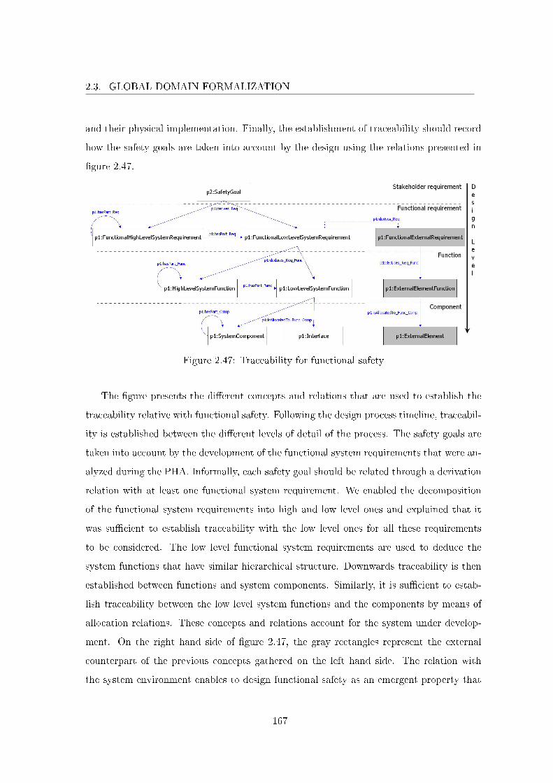
2.3. GLOBAL DOMAIN FORMALIZATION
and their physical implementation. Finally, the establishment of traceability should record
how the safety goals are taken into account by the design using the relations presented in
�gure 2.47.
Figure 2.47: Traceability for functional safety
The �gure presents the di�erent concepts and relations that are used to establish the
traceability relative with functional safety. Following the design process timeline, traceabil-
ity is established between the di�erent levels of detail of the process. The safety goals are
taken into account by the development of the functional system requirements that were an-
alyzed during the PHA. Informally, each safety goal should be related through a derivation
relation with at least one functional system requirement. We enabled the decomposition
of the functional system requirements into high and low level ones and explained that it
was su�cient to establish traceability with the low level ones for all these requirements
to be considered. The low level functional system requirements are used to deduce the
system functions that have similar hierarchical structure. Downwards traceability is then
established between functions and system components. Similarly, it is su�cient to estab-
lish traceability between the low level system functions and the components by means of
allocation relations. These concepts and relations account for the system under develop-
ment. On the right hand side of �gure 2.47, the gray rectangles represent the external
counterpart of the previous concepts gathered on the left hand side. The relation with
the system environment enables to design functional safety as an emergent property that
167
2.3. GLOBAL DOMAIN FORMALIZATION
can be observed at the adequate level of detail. The functional requirements, functions
and components that are external to the system have the same structure with the only
di�erence that we disabled their decomposition. The only point of detail concerns the
functional external requirements. They can be related directly with the safety goals (as
stakeholders requirements) but we really want to record the relation with the functional
system requirements to explain that these external elements are indirectly involved in the
functional safety of the system under development.
Finally, in addition to the informal semantics that the structure of the information
needs to capture, we have to verify that traceability has been established in a consistent
manner. The axioms on cardinality used in the ontology re�ect the notion of integrity
constraints that need to be ful�lled to conclude on the completeness of the information
recorded inside the ontology. If the ontology (including the individuals) is consistent then
all the integrity constraints are satis�ed (and reciprocally). Clearly, this veri�cation is
possible only at the end of the design process when all the information has been given and
all individuals introduced. Each cardinality constraint can and should however be veri�ed
independently following the design process timeline when necessary information is available
by using a query language.
2.3.2.2 ASIL Propagation.
As mentioned in section 2.2.2.2, ISO 26262 is vague concerning ASIL assignment. It
only speci�es how the ASIL is assigned to the safety goals and how the ASIL is assigned
to architectural system elements from the ASIL of the functional safety requirements in
relation. We already presented the assignment of the ASIL to the safety goals. For the
architectural elements, the rule is that the maximum ASIL of the functional safety require-
ments in relation with an architectural element is assigned to it. We retain this general
idea that the assignment of the ASIL should be conservative of the maximum ASIL of the
elements in relation.
Traceability records how functional safety is taken into account by the design process
from the safety goals to the elements of systems engineering. If traceability is correctly
established as presented in the previous section, it becomes possible to semi-automatically
168
2.3. GLOBAL DOMAIN FORMALIZATION
assign an ASIL to the elements of systems engineering by propagating the ASIL from the
safety goals. This is done using traceability relations. We called this a priori analysis ASIL
propagation. The analysis is semi-automatic because ASIL can be reduced a posteriori
using criticality analysis. Making this analysis automatic would result in the ASIL prop-
agated (assigned) a priori to contradict the ASIL obtained with criticality analysis. For
example, suppose that we only have one safety goal with an ASIL D in the ontology. Using
ASIL propagation based on the traceability closure of the information, all the elements of
systems engineering would be assigned the same ASIL D. However, if criticality analysis
concludes that the ASIL of a speci�c architectural element can be tailored, for instance
to ASIL C, then this element would have two di�erent assigned ASIL, which contradicts
the cardinality constraints of exactly one ASIL for an element. Let us note that the auto-
matic propagation will propose highest ASIL required. The fact that some elements will
be assigned two di�erent ASIL will point out the necessity to check precisely its e�ective
value. In the following, ASIL propagation is presented with di�erent axioms and, as a
result of the state of a�air with ASIL tailoring, some of them must be considered with
particular attention which is stressed when needed. ASIL propagation is performed using
the traceability relations presented in �gure 2.47, from the most abstract level of detail to
the most concrete.
The ASIL of the safety goals can be propagated to the functional system requirements
related by p1:derives_Req. As di�erent safety goals can be related to the same require-
ment, the maximum ASIL of these safety goals has to be assigned to the functional system
requirement. Let maxASIL be the function that returns the highest ASIL of a set. Axiom
(2.58) can automatically assign the highest ASIL of the safety goals of a functional system
requirement to this functional system requirement. However, the safety goals can also come
from other interacting systems which functional safety can be impeded depending on the
correct functioning of our system. This is problematic and it results that this axiom is
actually not used for the automatic propagation. It is nonetheless saved as it represents
169
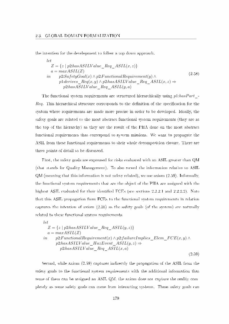
2.3. GLOBAL DOMAIN FORMALIZATION
the intention for the development to follow a top-down approach.
letZ = {z | p2:hasASILV alue_Req_ASIL(x, z)}a = maxASIL(Z)
in p2:SafetyGoal(x) ∧ p2:FunctionalRequirement(y) ∧p1:derives_Req(x, y) ∧ p2:hasASILV alue_Req_ASIL(x, z)⇒p2:hasASILV alue_Req_ASIL(y, a)
(2.58)
The functional system requirements are structured hierarchically using p1:hasPart_-
Req. This hierarchical structure corresponds to the de�nition of the speci�cation for the
system where requirements are made more precise in order to be developed. Ideally, the
safety goals are related to the most abstract functional system requirements (they are at
the top of the hierarchy) as they are the result of the PHA done on the most abstract
functional requirements that correspond to system missions. We want to propagate the
ASIL from these functional requirements to their whole decomposition closure. There are
three points of detail to be discussed.
First, the safety goals are expressed for risks evaluated with an ASIL greater than QM
(that stands for Quality Management). To also record the information relative to ASIL
QM (meaning that this information is not safety related), we use axiom (2.59). Informally,
the functional system requirements that are the object of the PHA are assigned with the
highest ASIL evaluated for their identi�ed FCEs (see sections 2.2.2.1 and 2.2.2.2). Note
that this ASIL propagation from FCEs to the functional system requirements in relation
captures the intention of axiom (2.58) as the safety goals (of the system) are naturally
related to these functional system requirements.
letZ = {z | p2:hasASILV alue_Req_ASIL(y, z)}a = maxASIL(Z)
in p2:FunctionalRequirement(x) ∧ p2:failureImplies_Elem_FCE(x, y) ∧p2:hasASILV alue_HazEvent_ASIL(y, z)⇒p2:hasASILV alue_Req_ASIL(x, a)
(2.59)
Second, while axiom (2.59) captures indirectly the propagation of the ASIL from the
safety goals to the functional system requirements with the additional information that
some of them can be assigned an ASIL QM, the axiom does not capture the reality com-
pletely as some safety goals can come from interacting systems. These safety goals can
170
2.3. GLOBAL DOMAIN FORMALIZATION
actually be related to more precise requirements than the functional system requirements
at the top of the hierarchy which has to be considered for the propagation. For instance,
assume that we are developing a brake system. The most abstract requirement that cor-
responds to the system mission of deceleration is "The braking system shall decelerate the
vehicle". Using the relation of decomposition, this requirement is made more precise and
the deceleration is actually possible by capturing information about the vehicle speed: "The
braking system shall capture the longitudinal speed of the vehicle". Naturally, deceleration
is safety critical and the requirement should be assigned an ASIL D that is propagated
throughout its decomposition closure. For the purpose of the example, we assign an ASIL
C to the two requirements. The information on the longitudinal speed is also needed by
the steering system. At Renault, a safety goal actually corresponds to the direct negation
of a feared customer event with an ASIL. This enables to address functional safety at the
customer level where the safety property is observable. The dysfunctional studies for the
steering system resulted in the de�nition of the safety goal "No loss of steering, ASIL D"
and the assignment of this same integrity level to the external functional requirement "The
braking system shall send the longitudinal speed of the vehicle". For the braking system,
this requirement is a safety goal (and a stakeholder requirement) that relates with a func-
tional system requirement part of the decomposition of the capture of the longitudinal
speed. In this case, propagating the ASIL of the functional requirements will result in the
assignment of two di�erent ASILs to some requirements. Naturally, the most stringent has
to be assigned.
Third, ASIL decomposition can be applied toany high level functional system require-
ment, see section 2.2.2.2. If a requirement is the object of ASIL decomposition, information
on objective ASIL (i.e., the ASIL preceding ASIL decomposition) must also be recorded
and propagated.
For space reasons, further axioms that are used for ASIL propagation are given in
appendix B. ASIL propagation in the hierarchy of functional system requirements addresses
the previous issues and is performed with the axioms gathered in appendix B. Note that
the safety goals of the system are intended to be related to all the top level requirements
in the hierarchy of the functional system requirements. This was not enforced but can be
171
2.3. GLOBAL DOMAIN FORMALIZATION
easily checked.
Axiom (B.1) expresses that a functional system requirement is assigned the highest
ASIL among the ASILs of its direct super-requirements that are not the object of ASIL
decomposition, its related safety goals, and of the relevant part of ASIL decomposition
the requirement (as a sub-requirement) is the object of. Then, if a requirement is the
object of ASIL decomposition, its sub-requirements that have their ASIL tailored and
their hierarchical closure are assigned an objective ASIL (i.e., the ASIL of the super-
requirement).
Axiom (B.2) states that a functional system sub-requirement is assigned the highest
ASIL as an objective ASIL among the ASIL of the super-requirement that is the object
of ASIL decomposition. This also concerns the sub-requirement and the objective ASIL of
its direct super-requirements.
Following �gure 2.47, we now study ASIL propagation from the functional system
requirements to the system functions. The propagation of the ASIL from the safety goal
throughout the hierarchy of functional system requirements is correctly done, i.e., the
highest ASIL has been assigned and all the low level functional system requirements have
an ASIL attribute instantiated. In addition, information about objective ASIL has also
been propagated if it applies. As we explained, in order to take into account all the high
level functional system requirements, it is su�cient that only the low level ones are related
to the functions. This still applies to safety aspects so the propagation is de�ned from the
low level functional system requirements throughout the hierarchy of system functions.
Axiom (B.3) expresses that a system function that has no ASIL assigned, is assigned
the highest ASIL among the ASILs of both its direct super-functions and its related low
level functional system requirements.
Axiom (B.4) assigns objective ASIL to system function in the same way.
As previously discussed, the system functions (as architectural elements) can be subject
to ASIL tailoring as a result of criticality analysis. If axiom (B.3) is used to e�ectively
assign the ASIL to the system functions, ASIL tailoring will possibly assign a di�erent
ASIL to some of them and result in a contradiction. Moreover, part of the propagation
172
2.3. GLOBAL DOMAIN FORMALIZATION
could also be too restrictive as an ASIL that is too high is assigned to the sub-functions of
the function that have seen its ASIL tailored by criticality analysis. In order to ensure that
we do not assign two di�erent ASIL to the same function, the consequences of axiom (B.3)
(i.e., the assignment of the ASIL to the functions) are treated only as entailed conclusions
that must not be added to the ontology until criticality analysis has ended for the functional
architecture.
Let us note that it is possible that not all the system functions are assigned with an
ASIL (even as entailed conclusions) as the structure enables to relate the functional system
requirements to sub-functions. Traceability (more precisely, the cardinality constraints and
the use of axiom (B.3)) ensures that all the low level system functions have an ASIL which
is enough to present ASIL propagation. We nevertheless de�ned that all the functions
should have an ASIL so the capability to backward-propagate the ASIL from the low level
functions to the top of the hierarchy exists but is not presented.
Similarly, now that all the low level system functions have an ASIL assigned (this is
su�cient for the consideration of all the system functions), it is propagated to the system
components.
Axiom (B.5) expresses that a system component that is not already assigned with an
ASIL is assigned the highest ASIL among the ASILs of its direct super-components and
its related low level system functions.
Axiom (B.6) assigns objective ASIL to system components in the same way.
Criticality analysis can also be used on the components for the tailoring of their ASIL,
the consequences of axiom (B.5) are treated only as entailed conclusions until criticality
analysis has ended for the physical architecture. Similarly, functional system requirements
can be related to sub-functions, low level system functions can be allocated to system
sub-components resulting in the possible existence of a component with no ASIL assigned
to it. It is important that all the components have an assigned ASIL. The components
partitioning into hardware and software re�ects the selection of which components will be
subject to further development (at hardware and software level) with speci�c requirements
of ISO 26262 de�ned by the ASIL of the component. As with axiom (B.5), all low level
173
2.3. GLOBAL DOMAIN FORMALIZATION
components are assigned to an ASIL, we can fully (i.e., completely) backward-propagate
the ASIL of the components for all the components to have an ASIL.
Axiom (B.7) (respectively axiom (B.8)) states that a system component that is not
already assigned with an ASIL (respectively objective ASIL) is assigned the highest ASIL
(respectively objective ASIL) among the ASILs (respectively objective ASILs) of its direct
sub-components. The consequences of these axioms can be produced but are also treated as
information that is not added to the ontology as they can be subject to criticality analysis.
Finally, we address the propagation of the ASIL to the elements that are part of the
system environment. As can be seen in �gure 2.47, the functional external requirements
are derived from the functional system requirements. This traceability between these two
types of requirements should be inspected with care. It is possible and it makes sense to
derive a functional external requirement from an abstract functional system requirement.
However it is possible, because of ASIL decomposition, that we assign an ASIL that is too
high to an external requirement. Therefore the traceability has to be established with the
functional system requirement that is the less abstract.
Axiom (B.9) propagates the correct ASIL to all the functional external requirement
(the highest ASIL of the functional system requirements in relation with one functional
external requirement is assigned to this requirement).
Axiom (B.10) does the same for the objective ASIL of the functional external require-
ments.
Axiom (B.11) propagates the ASIL from the external requirements to the external
functions
Axiom (B.12) is the similar counterpart of axiom (B.11) for the objective ASIL.
Applying axioms (B.13) and (B.14) will respectively result in propagating the ASIL and
objective ASIL at component level from the external functions to the external components
(external system elements).
174
2.3. GLOBAL DOMAIN FORMALIZATION
2.3.2.3 Conclusion
This section covers the interpretation of ISO 26262 speci�cally for Renault. In this
approach, the safety studies start as early as possible. Safety aspects represented by the
ASIL are integrated in the most abstract system elements that will be made precise along
the design process timeline. Based on the system and safety ontology, ASIL assignment
is presented as the semi-automatic propagation of the ASIL from these most abstract
elements to the most concrete ones at system level. If the general idea for ASIL assignment
is relatively shared by all the actors of functional safety, it is still done manually in practice
as a result of document-centric approaches. Here, ASIL propagation is de�ned precisely
for ASIL assignment to be done correctly.
2.3.3 Conclusion
In this section, we presented the domain ontology for both systems and functional
safety engineers. It is de�ned by integrating the two ontologies from section 2.2. This
made apparent the ambiguities of the universe of discourse that had to be solved when
these two domains are confronted with one another. The result is a systems engineering
and functional safety ontology. It de�nes formally the concepts and relations of the two
domains enabling precise communication between the systems and safety engineers. Specif-
ically, the now shared conceptualization solves loss of knowledge at the processes interface.
Moreover, it is an asset for the synergy of all the engineers and encourage for their tighter
collaboration. As an example of these synergies, ASIL propagation has been presented. It
exploits traceability to support the correct top-down propagation of the safety aspects (i.e.,
the ASIL) to the elements of systems engineering. The same conclusions can be formulated
for any domain ontology. The two domains integration, however, increases the scope of
these conclusions. This exceeds the reach of this section, but, �nally, consistency is now a
property shared by the two domains.
The systems engineering and functional safety ontology is one of the concrete contri-
bution of this work. As an answer to a need for better formalization, it is the most precise
solution. The ontology is realized with the help of Protégé 3.4.44 which is an editor of
4protege.stanford.edu
175
2.4. ONTOLOGY CENTRIC DESIGN APPROACH FOR SAFETY CRITICALAUTOMOTIVE MECHATRONICS SYSTEMS
OWL ontologies. This version of Protégé includes in particular a plug-in for SWRL and
an interface with the rule engine Jess5 to execute SWRL rules. As of now, the ontology
consists in 140 classes, 103 properties and 391 constraints. The generated documentation is
available at the following address: http://cedric.cnam.fr/~taofif_o/. In section 2.4,
we present the extent of having our domain ontology to improve the design process at
Renault.
2.4 Ontology Centric Design Approach for Safety Critical
Automotive Mechatronics Systems
The development of automotive mechatronic systems requires the participation of dif-
ferent professional �elds (e.g., vehicle architecture, mechanics, electronics, software, etc.),
each having its own language, its own jargon. Knowledge and information are often im-
plicit to one speci�c professional �eld. They are known to experts or specialists of the
profession, but are not always well capitalized and, therefore, they are unknown to the
other �elds or, even worse, lost if those experts or specialists change of position. It is the
role of system engineers to e�ectively take into account all those system stakeholders (i.e.,
the professional �elds concerned with the system) and orchestrate their contributions in
the big picture as to develop a correct system solution. We underline in particular the
heterogeneous nature of the automotive industry where many tools (and languages) can be
used by Renault and its suppliers. For example, used or considered tools include (but are
not limited to) Reqtify for requirements management and traceability, UML / SysML Pa-
pyrus or Enterprise architect for model development, ArKItect for the whole development
process including safety activities, Matlab/Simulink for the analysis of functional behav-
ior, Statemate for the analysis of physical behavior, Aralia for the development of fault
trees, and so on... System engineers must overcome a consistency problem to integrate this
heterogeneous environment.
From a syntactic point of view, the consequences are not too severe. Syntax consistency
problems arise when two di�erent terms are used to denominate one same thing. As a usual
example, we often work with documents and models that have terms in English and French
5protege.cim3.net/cgi-bin/wiki.pl?SWRLTab/
176
2.4. ONTOLOGY CENTRIC DESIGN APPROACH FOR SAFETY CRITICALAUTOMOTIVE MECHATRONICS SYSTEMS
languages. Consequently, we might say that working with two models with di�erent names
just takes more time. As the meaning is not altered, we can somehow understand how it
all comes down together. It is just a matter of realizing "he calls this thing that way" and
living with that. From the semantic point of view, however, the problem takes a completely
di�erent dimension. The problem can be resumed to the utilization of one same term by
two di�erent professional �elds to designate respectively two di�erent concepts. This can
lead to situations that are so contradictory that we might end up trying to solve a problem
with no solution. Ultimately, when the actors of di�erent professional �elds exchange
some information or knowledge; some are lost either by communication omission or by
misinterpretation of this information [Burr et al. 2005]. The other possible consistency
problem is less fundamental but equally important and consists in inter-domain consistency.
As the development is executed in parallel by di�erent �elds, each of them relies only on
the information relevant for their studies. The information manipulated by the di�erent
�elds (used or produced information) can intersect and the di�culty is to guarantee that
all the �elds are working with consistent information ensuring consistency of the design
process [Papadopoulos et al. 2001].
Section 2.4.1 presents the systems engineering and functional safety ontology as the
reference model placed at the heart of the system design process. The ontology enables
to guarantee the design process consistency. These ideas were the subject of a precedent
communication that can be found in [Chalé Góngora et al. 2011]. Section 2.4.2 presents
our design approach for safety critical automotive mechatronics systems at Renault which
is more precise than the current general one. Finally, section 2.4.3 gives the conclusion.
2.4.1 Place of the Ontology in the Design Process
Renault is currently transitioning to a Model-Based System Engineering (MBSE) pro-
cess for the development of its vehicle systems. The use of formal and informal (but
consistent) models to create a common semantic model is expected to facilitate systems
engineering activities and to avoid the encountered drawbacks of previous document-centric
implementations of the process, which were lacking semantic consistency among the dif-
ferent modeled objects [Chalé Góngora et al. 2009, 2010]. The objective of MBSE is to
177
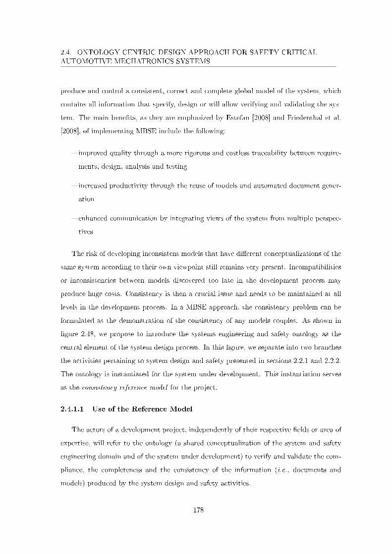
2.4. ONTOLOGY CENTRIC DESIGN APPROACH FOR SAFETY CRITICALAUTOMOTIVE MECHATRONICS SYSTEMS
produce and control a consistent, correct and complete global model of the system, which
contains all information that specify, design or will allow verifying and validating the sys-
tem. The main bene�ts, as they are emphasized by Estefan [2008] and Friedenthal et al.
[2008], of implementing MBSE include the following:
� improved quality through a more rigorous and costless traceability between require-
ments, design, analysis and testing
� increased productivity through the reuse of models and automated document gener-
ation
� enhanced communication by integrating views of the system from multiple perspec-
tives
The risk of developing inconsistent models that have di�erent conceptualizations of the
same system according to their own viewpoint still remains very present. Incompatibilities
or inconsistencies between models discovered too late in the development process may
produce huge costs. Consistency is then a crucial issue and needs to be maintained at all
levels in the development process. In a MBSE approach, the consistency problem can be
formulated as the demonstration of the consistency of any models couples. As shown in
�gure 2.48, we propose to introduce the systems engineering and safety ontology as the
central element of the system design process. In this �gure, we separate into two branches
the activities pertaining to system design and safety presented in sections 2.2.1 and 2.2.2.
The ontology is instantiated for the system under development. This instantiation serves
as the consistency reference model for the project.
2.4.1.1 Use of the Reference Model
The actors of a development project, independently of their respective �elds or area of
expertise, will refer to the ontology (a shared conceptualization of the system and safety
engineering domain and of the system under development) to verify and validate the com-
pliance, the completeness and the consistency of the information (i.e., documents and
models) produced by the system design and safety activities.
178
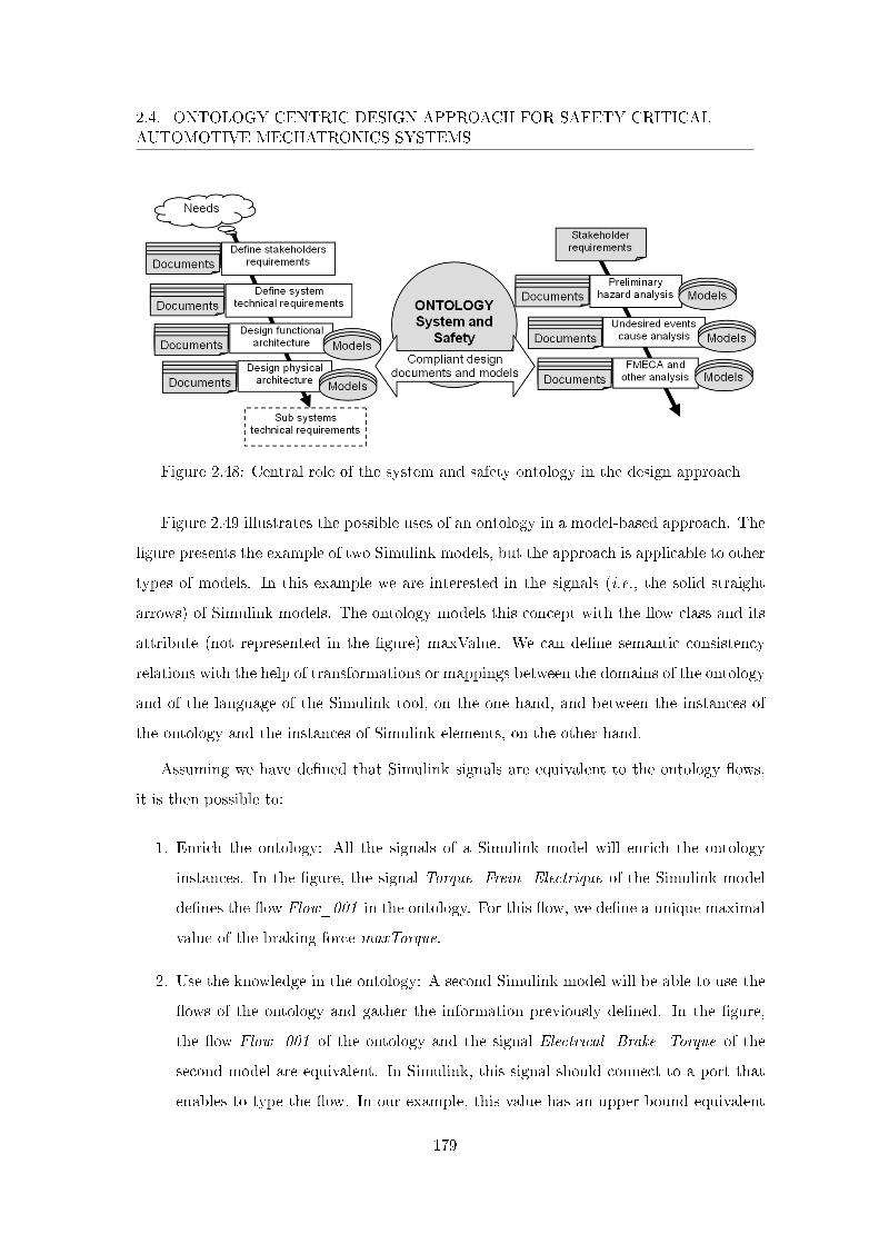
2.4. ONTOLOGY CENTRIC DESIGN APPROACH FOR SAFETY CRITICALAUTOMOTIVE MECHATRONICS SYSTEMS
Figure 2.48: Central role of the system and safety ontology in the design approach
Figure 2.49 illustrates the possible uses of an ontology in a model-based approach. The
�gure presents the example of two Simulink models, but the approach is applicable to other
types of models. In this example we are interested in the signals (i.e., the solid straight
arrows) of Simulink models. The ontology models this concept with the �ow class and its
attribute (not represented in the �gure) maxValue. We can de�ne semantic consistency
relations with the help of transformations or mappings between the domains of the ontology
and of the language of the Simulink tool, on the one hand, and between the instances of
the ontology and the instances of Simulink elements, on the other hand.
Assuming we have de�ned that Simulink signals are equivalent to the ontology �ows,
it is then possible to:
1. Enrich the ontology: All the signals of a Simulink model will enrich the ontology
instances. In the �gure, the signal Torque_Frein_Electrique of the Simulink model
de�nes the �ow Flow_001 in the ontology. For this �ow, we de�ne a unique maximal
value of the braking force maxTorque.
2. Use the knowledge in the ontology: A second Simulink model will be able to use the
�ows of the ontology and gather the information previously de�ned. In the �gure,
the �ow Flow_001 of the ontology and the signal Electrical_Brake_Torque of the
second model are equivalent. In Simulink, this signal should connect to a port that
enables to type the �ow. In our example, this value has an upper bound equivalent
179
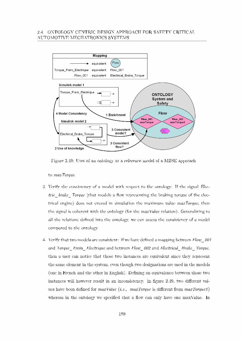
2.4. ONTOLOGY CENTRIC DESIGN APPROACH FOR SAFETY CRITICALAUTOMOTIVE MECHATRONICS SYSTEMS
Figure 2.49: Uses of an ontology as a reference model of a MBSE approach
to maxTorque.
3. Verify the consistency of a model with respect to the ontology: If the signal Elec-
tric_brake_Torque (that models a �ow representing the braking torque of the elec-
trical engine) does not exceed in simulation the maximum value maxTorque, then
the signal is coherent with the ontology (for the maxValue relation). Generalizing to
all the relations de�ned into the ontology, we can assess the consistency of a model
compared to the ontology.
4. Verify that two models are consistent: If we have de�ned a mapping between Flow_001
and Torque_Frein_Electrique and between Flow_002 and Electrical_Brake_Torque,
then a user can notice that those two instances are equivalent since they represent
the same element in the system, even though two designations are used in the models
(one in French and the other in English). De�ning an equivalence between those two
instances will however result in an inconsistency. In �gure 2.49, two di�erent val-
ues have been de�ned for maxValue (i.e., maxTorque is di�erent from maxTorque2 )
whereas in the ontology we speci�ed that a �ow can only have one maxValue. In
180
2.4. ONTOLOGY CENTRIC DESIGN APPROACH FOR SAFETY CRITICALAUTOMOTIVE MECHATRONICS SYSTEMS
the opposite case (i.e., maxTorque is equal to maxTorque2 ) and generalizing, the
two models are consistent and, once again, they describe the same system and we
have some evidences that a solution for the system exists. Generalizing even more,
it becomes possible to verify some form of consistency of the whole system design
through an ontology.
In a general manner, the project actors create information in documents and models.
The ontology will enable them to verify the consistency, the completeness and the confor-
mity of the produced information. Once veri�ed, the new information can be imported
into the ontology [Kergosien et al. 2010]. The ontology can also be viewed as a knowledge
base. Queries can then be developed to bring relevant information to the surface such as
the list of requirements related to one speci�c function for example. Reference information
can be exploited to produce new views (system views) and generate new information [Sure
et al. 2002]. In our ontology, we generate information about a priori ASIL for instance.
The ontology is therefore the reference (model) that, on the one hand, contains the ref-
erence information that describes the system under development and, on the other hand,
connects the information it contains with the information present in the documents and
models produced during the course of the system development project.
Another key element in MBSE is the transformation of models which allows the de�-
nition and implementation of operations on models. Using model transformation enables
the automated or computer assisted development of a system from its corresponding mod-
els. Similarly to its role to ensure semantic consistency of models, the ontology can ensure
semantic integrity when using model transformation. This is the object of the next section.
2.4.1.2 On Model Transformation
Model transformation is an essential part of the MDA framework (see section 1.2.3.2).
In this framework, models are based on meta-models that comply with the Meta-Object
Facility (MOF) standard of the OMG that uses the layered concepts of instance, model,
meta-model and meta-meta-model. Model transformation is the automatic generation of
a target model (the result of the transformation) from a source model (the input of the
181
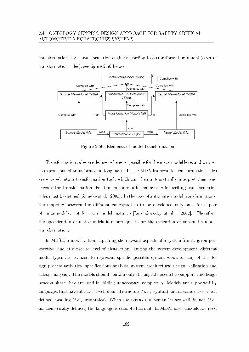
2.4. ONTOLOGY CENTRIC DESIGN APPROACH FOR SAFETY CRITICALAUTOMOTIVE MECHATRONICS SYSTEMS
transformation) by a transformation engine according to a transformation model (a set of
transformation rules), see �gure 2.50 below.
Figure 2.50: Elements of model transformation
Transformation rules are de�ned whenever possible for the meta-model level and written
as expressions of transformation languages. In the MDA framework, transformation rules
are entered into a transformation tool, which can then automatically interpret them and
execute the transformation. For that purpose, a formal syntax for writing transformation
rules must be de�ned [Anneke et al. 2003]. In the case of automatic model transformations,
the mapping between the di�erent concepts has to be developed only once for a pair
of meta-models, not for each model instance [Levendovszky et al. 2002]. Therefore,
the speci�cation of meta-models is a prerequisite for the execution of automatic model
transformation.
In MBSE, a model allows capturing the relevant aspects of a system from a given per-
spective, and at a precise level of abstraction. During the system development, di�erent
model types are realized to represent speci�c possible system views for any of the de-
sign process activities (speci�cations analysis, system architectural design, validation and
safety analysis). The models should contain only the aspects needed to support the design
process phase they are used in, hiding unnecessary complexity. Models are supported by
languages that have at least a well de�ned structure (i.e., syntax) and in some cases a well
de�ned meaning (i.e., semantics). When the syntax and semantics are well de�ned (i.e.,
mathematically de�ned) the language is connoted formal. In MDA, meta-models are used
182
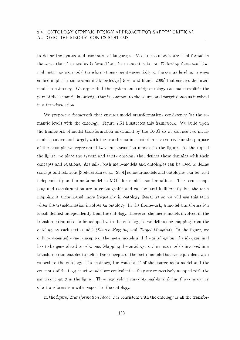
2.4. ONTOLOGY CENTRIC DESIGN APPROACH FOR SAFETY CRITICALAUTOMOTIVE MECHATRONICS SYSTEMS
to de�ne the syntax and semantics of languages. Most meta-models are semi formal in
the sense that their syntax is formal but their semantics is not. Following those semi for-
mal meta-models, model transformations operate essentially at the syntax level but always
embed implicitly some semantic knowledge [Roser and Bauer 2005] that ensures the inter-
model consistency. We argue that the system and safety ontology can make explicit the
part of the semantic knowledge that is common to the source and target domains involved
in a transformation.
We propose a framework that ensures model transformations consistency (at the se-
mantic level) with the ontology. Figure 2.51 illustrates this framework. We build upon
the framework of model transformation as de�ned by the OMG so we can see two meta-
models, source and target, with the transformation model in the center. For the purpose
of the example we represented two transformation models in the �gure. At the top of
the �gure, we place the system and safety ontology that de�nes those domains with their
concepts and relations. Actually, both meta-models and ontologies can be used to de�ne
concept and relations [Söderström et al. 2001] so meta-models and ontologies can be used
independently as the meta-model in MOF for model transformations. The terms map-
ping and transformation are interchangeable and can be used indi�erently but the term
mapping is encountered more frequently in ontology literature so we will use this term
when the transformation involves an ontology. In the framework, a model transformation
is still de�ned independently from the ontology. However, the meta-models involved in the
transformation need to be mapped with the ontology, so we de�ne one mapping from the
ontology to each meta-model (Source Mapping and Target Mapping). In the �gure, we
only represented some concepts of the meta-models and the ontology but the idea can and
has to be generalized to relations. Mapping the ontology to the meta-models involved in a
transformation enables to de�ne the concepts of the meta-models that are equivalent with
respect to the ontology. For instance, the concept C of the source meta-model and the
concept i of the target meta-model are equivalent as they are respectively mapped with the
same concept 3 in the �gure. Those equivalent concepts enable to de�ne the consistency
of a transformation with respect to the ontology.
In the �gure, Transformation Model 1 is consistent with the ontology as all the transfor-
183
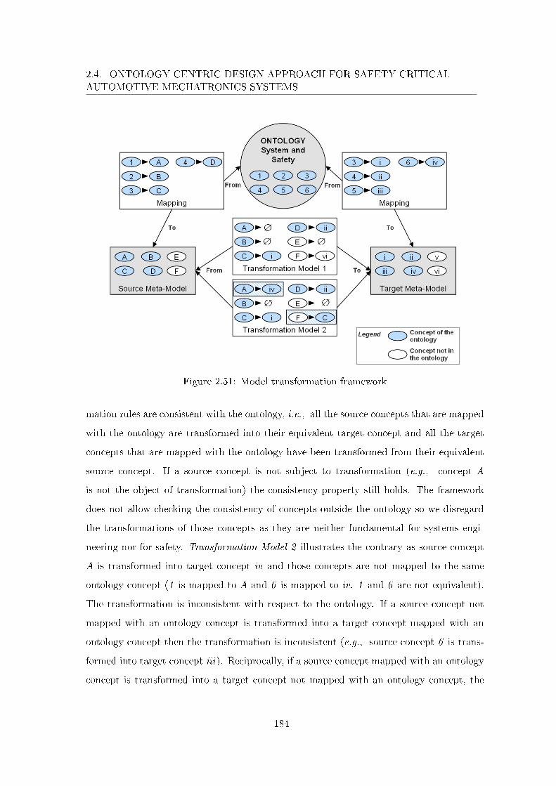
2.4. ONTOLOGY CENTRIC DESIGN APPROACH FOR SAFETY CRITICALAUTOMOTIVE MECHATRONICS SYSTEMS
Figure 2.51: Model transformation framework
mation rules are consistent with the ontology, i.e., all the source concepts that are mapped
with the ontology are transformed into their equivalent target concept and all the target
concepts that are mapped with the ontology have been transformed from their equivalent
source concept. If a source concept is not subject to transformation (e.g., concept A
is not the object of transformation) the consistency property still holds. The framework
does not allow checking the consistency of concepts outside the ontology so we disregard
the transformations of those concepts as they are neither fundamental for systems engi-
neering nor for safety. Transformation Model 2 illustrates the contrary as source concept
A is transformed into target concept iv and those concepts are not mapped to the same
ontology concept (1 is mapped to A and 6 is mapped to iv. 1 and 6 are not equivalent).
The transformation is inconsistent with respect to the ontology. If a source concept not
mapped with an ontology concept is transformed into a target concept mapped with an
ontology concept then the transformation is inconsistent (e.g., source concept 6 is trans-
formed into target concept iii). Reciprocally, if a source concept mapped with an ontology
concept is transformed into a target concept not mapped with an ontology concept, the
184

2.4. ONTOLOGY CENTRIC DESIGN APPROACH FOR SAFETY CRITICALAUTOMOTIVE MECHATRONICS SYSTEMS
transformation is inconsistent.
This framework enables to guarantee tools interoperability at the semantic level. The
ontology presented in the previous section explains how system and safety engineering have
to be understood. Within the framework, we can verify that the SE design tools implement
correctly the ontology at the semantic level (i.e., the meta-model implemented by the tool
is consistent with the ontology). Moreover, the framework shows how those tools can
inter-operate seamlessly via model transformations that are consistent with the ontology.
Finally, this framework enables to evaluate if the language used and the transformations
proposed by a tool correctly implement the ontology and, therefore, if this tool can be used
to support the system design process at Renault.
2.4.1.3 Conclusion
In this section, we presented the numerous advantages of an ontology based devel-
opment. In a heterogeneous environment where di�erent domains have to communicate,
ontologies can solve the problem of semantic integration. This is naturally very constraining
as mappings have to be de�ned between the ontology and each meta-model used in speci�c
tools. This issue is however inherently related to tool interoperability that is criticized with
"the ambient paradigm of distribution ("tools that hardly work together except hopefully
one day")" [Albinet et al. 2010]. Tools are actually developed, independently (di�erent
tools), and for di�erent manufacturers. Making them work together remains manufacturer
speci�c. The ontology can help answering if a tool actually corresponds to Renault needs
(it is consistent with the ontology), through mapping de�nitions, and therefore if it can
be integrated in a development process for Renault. Finally, not only ontologies enable
to ensure seamlessness during the design process, it does so at the semantic level. The
next section presents our recommendations to improve the quality of the complex design
activity. It is a general proposition that could be used at Renault which is used as a speci�c
example.
185
2.4. ONTOLOGY CENTRIC DESIGN APPROACH FOR SAFETY CRITICALAUTOMOTIVE MECHATRONICS SYSTEMS
2.4.2 Ontology Centric Design Process
In order to improve Renault design process and facilitate its transition from document-
centric to model-based systems engineering, we chose to introduce an ontology that can
guarantee the whole design process consistency at the semantic level. We expect this on-
tology to improve the design process in a number of ways. First, the activity of writing
requirements and establishing their traceability is done with the semantic interpretation
de�ned in the ontology and can somewhat bridge the gap between the informal world of
discourse and the more formal worlds of models. Secondly, making usually implicit knowl-
edge explicit further enables the front loading of activities, while engineers remain capable
to make informed decisions, and help to identify areas susceptible to automatic or semi-
automatic procedures used in Model-Based Design. In addition and more generally, going
towards more formalization (at the semantic level) and sharing the formalized conceptu-
alization is an enabler for reuse. Thirdly, committing to the ontology makes it possible
to work at inter-disciplinary level, the foundation coming from the fact that the system
is indeed the common rally point to di�erent professions. For instance, analysis such as
multi-model consistency and coherence gives con�dence that it is the same system that
is being built. Finally, incorporated concepts from ISO 26262 help to demonstrate the
compliance with this standard.
With respect to the amount of work that will be required for these improvements to
come to life, it seems particularly �tting and it is our recommendation to introduce a
new actor, an ontology engineer, whose role will consist in ensuring a seamless consistent
development. Considering the chaotic nature of current systems engineering practice (for
instance tools such as Powerpoint, Visio, Matlab/Simulink, Enterpise Architect, Parpyrus
and so on can be used to de�ne the system architecture), the actual challenge for the
transition to model-based systems engineering is to evaluate formalisms adequacy to Re-
nault needs in anticipation of a future domain speci�c language for Renault. As such, the
general design process remains unchanged and we introduce the ontology engineer role in
parallel to systems and functional safety engineer roles as can be seen in �gure 2.52 that
uses Business Process Modeling Notation (BPMN).
186
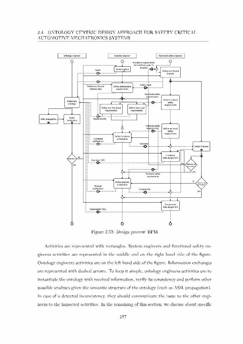
2.4. ONTOLOGY CENTRIC DESIGN APPROACH FOR SAFETY CRITICALAUTOMOTIVE MECHATRONICS SYSTEMS
Figure 2.52: Design process' BPM
Activities are represented with rectangles. System engineers and functional safety en-
gineers activities are represented in the middle and on the right hand side of the �gure.
Ontology engineers activities are on the left hand side of the �gure. Information exchanges
are represented with dashed arrows. To keep it simple, ontology engineers activities are to
instantiate the ontology with received information, verify its consistency and perform other
possible analyses given the semantic structure of the ontology (such as ASIL propagation).
In case of a detected inconsistency, they should communicate the issue to the other engi-
neers to the impacted activities. In the remaining of this section, we discuss about speci�c
187
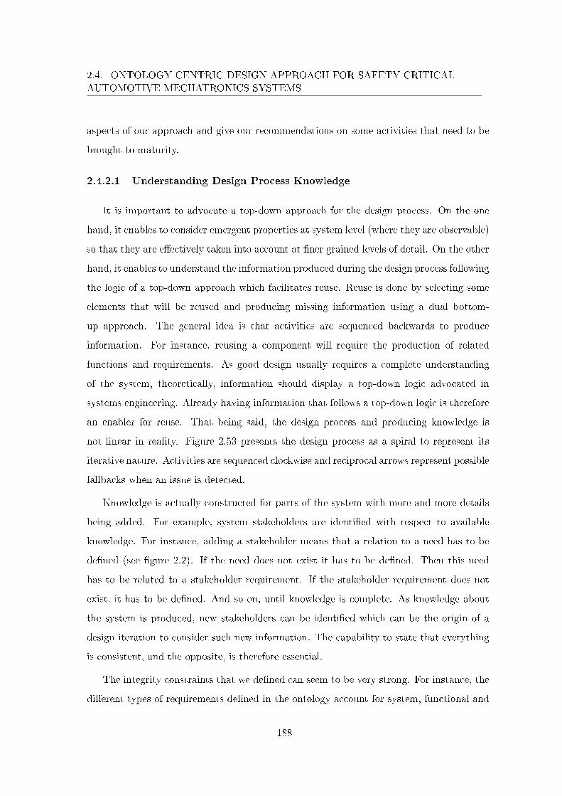
2.4. ONTOLOGY CENTRIC DESIGN APPROACH FOR SAFETY CRITICALAUTOMOTIVE MECHATRONICS SYSTEMS
aspects of our approach and give our recommendations on some activities that need to be
brought to maturity.
2.4.2.1 Understanding Design Process Knowledge
It is important to advocate a top-down approach for the design process. On the one
hand, it enables to consider emergent properties at system level (where they are observable)
so that they are e�ectively taken into account at �ner grained levels of detail. On the other
hand, it enables to understand the information produced during the design process following
the logic of a top-down approach which facilitates reuse. Reuse is done by selecting some
elements that will be reused and producing missing information using a dual bottom-
up approach. The general idea is that activities are sequenced backwards to produce
information. For instance, reusing a component will require the production of related
functions and requirements. As good design usually requires a complete understanding
of the system, theoretically, information should display a top-down logic advocated in
systems engineering. Already having information that follows a top-down logic is therefore
an enabler for reuse. That being said, the design process and producing knowledge is
not linear in reality. Figure 2.53 presents the design process as a spiral to represent its
iterative nature. Activities are sequenced clockwise and reciprocal arrows represent possible
fallbacks when an issue is detected.
Knowledge is actually constructed for parts of the system with more and more details
being added. For example, system stakeholders are identi�ed with respect to available
knowledge. For instance, adding a stakeholder means that a relation to a need has to be
de�ned (see �gure 2.2). If the need does not exist it has to be de�ned. Then this need
has to be related to a stakeholder requirement. If the stakeholder requirement does not
exist, it has to be de�ned. And so on, until knowledge is complete. As knowledge about
the system is produced, new stakeholders can be identi�ed which can be the origin of a
design iteration to consider such new information. The capability to state that everything
is consistent, and the opposite, is therefore essential.
The integrity constraints that we de�ned can seem to be very strong. For instance, the
di�erent types of requirements de�ned in the ontology account for system, functional and
188
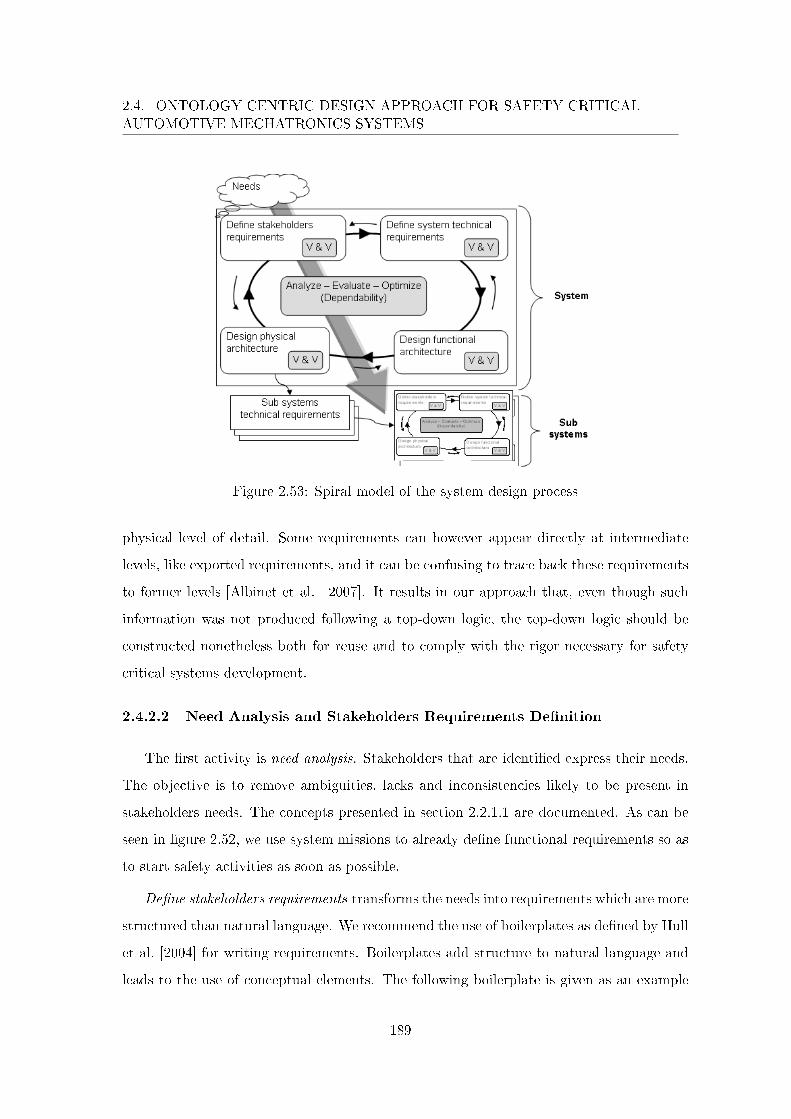
2.4. ONTOLOGY CENTRIC DESIGN APPROACH FOR SAFETY CRITICALAUTOMOTIVE MECHATRONICS SYSTEMS
Figure 2.53: Spiral model of the system design process
physical level of detail. Some requirements can however appear directly at intermediate
levels, like exported requirements, and it can be confusing to trace back these requirements
to former levels [Albinet et al. 2007]. It results in our approach that, even though such
information was not produced following a top-down logic, the top-down logic should be
constructed nonetheless both for reuse and to comply with the rigor necessary for safety
critical systems development.
2.4.2.2 Need Analysis and Stakeholders Requirements De�nition
The �rst activity is need analysis. Stakeholders that are identi�ed express their needs.
The objective is to remove ambiguities, lacks and inconsistencies likely to be present in
stakeholders needs. The concepts presented in section 2.2.1.1 are documented. As can be
seen in �gure 2.52, we use system missions to already de�ne functional requirements so as
to start safety activities as soon as possible.
De�ne stakeholders requirements transforms the needs into requirements which are more
structured than natural language. We recommend the use of boilerplates as de�ned by Hull
et al. [2004] for writing requirements. Boilerplates add structure to natural language and
leads to the use of conceptual elements. The following boilerplate is given as an example
189
2.4. ONTOLOGY CENTRIC DESIGN APPROACH FOR SAFETY CRITICALAUTOMOTIVE MECHATRONICS SYSTEMS
for stakeholders requirements:
The <stakeholder type> (shall or may) be able to <capability>
where stakeholder type is a stakeholder, verbs shall or may represent di�erent priorities
of requirements (high when using shall and low when using may) and capability represents
the functionality to be developed.
One particular type of stakeholders requirements are safety goals. Functional safety
engineers should be solicited by system engineers whenever risk of harm can be foreseen
in advance or even when they are not certain that it is the case. Usual safety critical
systems in the automotive are braking and steering. However the scope begins to enlarge
as new systems or even systems of systems are being developed at Renault such as electric
vehicles and automatic vehicle �eets. As explained in section 2.2.2.2, safety goals result
from the PHA. They are composed of a Feared Customer Event and an ASIL. In terms of
requirements, a safety goal actually corresponds to the direct negation of a feared customer
event with an ASIL so we propose the following boilerplate:
The <stakeholder type> shall not be subject to a <FCE>, ASIL <ASIL
level>
where stakeholder type is a stakeholder, FCE is the feared customer event in question
and ASIL level corresponds to A, B, C or D as de�ned in ISO 26262.
In general, ontology engineers receive all informations produced (here needs and stake-
holders requirements) and perform instantiate ontology in parallel (see �gure 2.52). The
di�culty comes from the heterogeneous and numerous formalisms used that are speci�c
to each project. For now, Renault general system design process is de�ned but it is in-
stantiated depending on the project. One project manager can choose to use speci�c tools
or use suppliers that can come with their respective tools. Other project managers can
make di�erent choices. In order to instantiate the ontology, mappings have to be de�ned.
For need analysis general purpose modeling languages such as SysML can be used but still
informal formalisms are more commonly used. For instance, techniques such as APTE6
method's "bête à cornes"7 can be used where some stakeholders are identi�ed and system
6http://www.methode-apte.com/7http://www.methode-apte.com/bete_a_cornes.htm
190
2.4. ONTOLOGY CENTRIC DESIGN APPROACH FOR SAFETY CRITICALAUTOMOTIVE MECHATRONICS SYSTEMS
goals de�ned. In both cases, these formalisms can present a delta with the ontology and
some level of interpretation is applied to de�ne a mapping. Implementing a mapping re-
mains arbitrary as complete coverage of the diversity of languages is unlikely. It is actually
the same for any activity. The rule in model-based design is to use a modeling language
but the actual transition will not be made until modeling languages and tools to be used
are clearly de�ned revealing necessary mappings implementation.
Assuming the ontology engineers have instantiated the ontology, the next activity is
verify consistency. This can be easily performed using a reasoner that understands the
ontology language. But more speci�c veri�cations can be made. As an example we de�ned
ASIL propagation in section 2.3.2 which is a useful analysis concerning functional safety as
we will see further in the discussion. Other relevant veri�cations are left to the engineer's
insight.
2.4.2.3 System Level Requirements De�nition
In �gure 2.52, we represented requirements de�nition in general focusing on functional
and non functional requirements. Naturally, requirements structure de�ned in section
2.2.1.2 is applicable. In the remainder, we focus on the consideration of functional safety
in the design process as illustrated in �gure 2.47 so non functional requirements de�nition
is not brought into the discussion.
Preliminary Hazard Analysis. In order for safety aspects to be included into the
functional "genes" of design, preliminary hazard analysis is performed as soon as missions
have been transformed into functional requirements. We have three recommendations for
this activity. First, the application of a failure model as presented in section 2.2.2.1 to
make the analysis more systematic. Second, PHA being completely reusable as is if done
at vehicle level, we cannot stress enough the reuse of PHA's lines from previous similar
projects. Finally, PHA output being safety goals, they should be written by applying the
speci�c boilerplate as presented in previous section 2.4.2.2.
Safety goals come with an assigned ASIL determined by following table 1.4 speci�ed in
ISO 26262. ASIL determination is formalized in the ontology (see section 2.2.2.2) there-
191
2.4. ONTOLOGY CENTRIC DESIGN APPROACH FOR SAFETY CRITICALAUTOMOTIVE MECHATRONICS SYSTEMS
fore, once PHA data are instantiated in the ontology, ontology engineers can verify both
that ASIL determination and safety goal's ASIL assignment have been done correctly.
In addition, they propagate the ASIL from hazardous events to their original functional
requirements.
Functional Requirements De�nition. Integrating systems engineering and functional
safety helped identify an important synergy between the two kinds of engineers. Now that
safety aspects are incorporated into stakeholders requirements, the system can actually be
developed towards acceptable risk following a top-down approach. Even though it should
be system engineers role to de�ne the system functional requirements, they can bene�t
greatly from functional safety engineers expertise to develop functional requirements that
intuitively correspond to additional functions that exist only to ensure safety. The goal is to
reduce design iterations by making systems and functional safety engineers work together
in a more collaborative manner rather than strictly in parallel. Systems engineer position
does not yet exist at Renault and systems engineering activities are actually partially per-
formed by di�erent actors depending on the project. For instance, the project manager can
be in charge of writing requirements while the electric and electronic architect (a position at
Renault) is responsible of functional and physical architecture production. Actually, many
design iterations exist for system architecture de�nition and related requirements. System
architecture are �rst produced without considering safety, and then secured architectures
are developed to take safety into account. Corresponding requirements are naturally also
de�ned iteratively. Safety engineers activities are performed in parallel and consist in, Pre-
liminary Hazard Analysis, de�nition of safety requirements, ASIL assignment and other
safety analyses. Usual communication between system engineers and safety engineers are
represented in �gure 2.52 with dashed arrows between the two roles. Using a common on-
tology can indirectly play the role of collaboration as consistency between design documents
and models can be ensured. Two scenarios are conceivable. First, project actors assigned
the role of system engineers and functional safety engineers (they are distinct for safety
critical systems according to ISO 26262) can also play the role of ontology engineers. They
add the information they are responsible for to the ontology, verify its consistency and use
192
2.4. ONTOLOGY CENTRIC DESIGN APPROACH FOR SAFETY CRITICALAUTOMOTIVE MECHATRONICS SYSTEMS
it as a knowledge base. Second, ontology engineering can be viewed as a new professional
�eld in the company and dedicated actors are assigned to the role of ontology engineers.
They receive information from systems and safety engineers, instantiate the ontology with
this information, verify its consistency, use it as a database and communicate points of
concerns when inconsistencies are detected. Using an ontology ensures that systems and
safety engineers are working on the same system in a more synchronized way. This can lead
to the front loading of safe architectures de�nition with their requirements and to design
iterations reduction as systems and safety engineers are working on information veri�ed to
be consistent.
Coming back to functional requirements de�nition, we recommend the use of the fol-
lowing boilerplate at system level:
The <system> shall <function>
where system is the system in development and function is a system function displaying
the functional nature of the requirement.
As presented in section 2.2.2.2, the main point of involving safety engineers in func-
tional requirements de�nition is to perform ASIL decomposition on functional require-
ments. Safety engineers have a better understanding when and how a function (a func-
tionality, not necessarily a system function) captured by the functional requirement can be
decomposed into functional requirements (which correspond to a safety mechanism, redun-
dancy for instance). This decomposition (or tailoring) is done a priori, independently of
any architecture, and further safety studies will be performed later in the process to verify
that tolerable risk is achieved (in function of the ASIL). Performing ASIL decomposition is
an asset of ISO 26262 as it follows systems engineering principle to think about the prob-
lem before thinking about the solution. To impose oneself with independence constraints
early in the design process can result in elegant and more performing solutions in terms of
architectures.
For ontology engineers, on reception of functional requirements, they instantiate the
ontology and verify ontology consistency. In particular, they have to make sure that
semantic relations usage (decomposition, derive etc.) upon natural discourse makes sense.
193
2.4. ONTOLOGY CENTRIC DESIGN APPROACH FOR SAFETY CRITICALAUTOMOTIVE MECHATRONICS SYSTEMS
They can verify the structure of the functional requirements and perform ASIL propagation
from top level functional requirements to low level ones (see section 2.3.2.2).
2.4.2.4 Functional and Physical Architecture De�nition
In de�ne functional architecture and de�ne physical architecture activities, functional
requirements are materialized into functions that are allocated to the components responsi-
ble for their execution. As explained in the previous section, we propose more synchroniza-
tion for systems and safety engineers through an ontology. Systems engineer are responsible
for system architectures de�nition. Functional safety engineers are responsible for these
architectures to be reasonably safe, i.e., they have to prove that both the architectures
development and the architectures respect evaluated risk for the system. Let us note that
risk evaluation was historically performed on system architectures devoid of safety-related
functions and safety mechanisms in order to obtain a correct appraisal of system's risk.
Even though the habit is still followed by safety practitioners, the approach proposed in
this work front loads risk evaluation on functional requirements that correspond to system
missions. It seems even more �tting for the analysis pertinence as it is more probable
that safety-related functions and safety mechanisms are not considered. As can be seen
in �gure 2.52, system architectures are de�ned by systems engineer that take into account
safety aspects provided by safety engineers in the form of functional and technical safety
requirements.
The hardships concerning requirements management and traceability, identi�ed by Al-
binet et al. [2010] for instance, is still relevant. Making sure that project actors justify their
work in relation to system requirements gives more con�dence that the project does not
deviate. Stemming from project tools heterogeneity, the capability to manage and trace
requirements from a textual document to di�erent modeling objects in di�erent tools is a
necessity. Tools such as Telelogic DOORS8 or Geensoft Reqtify9 are used for requirements
management. Naturally, for manufacturer speci�c needs, they have to be customized. The
ontology is a highly formalized attempt to express how traceability should be established
and understood.8http://www-01.ibm.com/software/awdtools/doors/productline/9http://www.3ds.com/products/catia/portfolio/geensoft/geensoft-product-lines/reqtify/
194
2.4. ONTOLOGY CENTRIC DESIGN APPROACH FOR SAFETY CRITICALAUTOMOTIVE MECHATRONICS SYSTEMS
Safety engineers role is to assign an ASIL on functions and components from the safety
goals. Precautions must be taken if a function or component failure can lead to the violation
of a safety goal. They are de�ned in ISO 26262 with respect to assigned ASIL. The
ontology formalizes how ASILs are assigned (see sections 2.2.2.2 and 2.3.2) which remained
ambiguous previously. In general, the ontology is an incredible asset for understanding a
domain. If creating an ontology requires for the formalized conceptualization to be shared,
new people (both internal or external to any company) that have to familiarize with the
domain will be able to do so with a more precise artifact than natural language (i.e., oral
communication or documents) or informal models.
Concerning ontology engineers, they perform ASIL propagation from the functional
requirements to the architectures exploiting the structure of instances as de�ned in section
2.3.2. As can be seen in �gure 2.52, they also receive functions ASIL assigned by safety
engineers. While we consider that functional safety engineers at Renault perform ASIL
assignment correctly (i.e., they do share our conceptualization), using suppliers is also a
possibility. In addition, be it engineers from Renault or suppliers, both are likely to make
human errors as ASIL assignment remains a manual activity. So, after performing ASIL
propagation and verifying the ontology consistency, ontology engineers point out to safety
engineers that one or more assignments may be erroneous if an inconsistency is found.
For instance, instantiating a function with an ASIL D as done by the safety engineer,
an inconsistency will be found if a di�erent ASIL is de�ned for the function by ASIL
propagation.
2.4.2.5 Conclusion
In order to improve the design process of safety critical systems at Renault to answer
ISO 26262 requirements, we �rst went through appropriating and capturing the domains
of systems and functional safety engineering. This enabled to identify favorable areas for
improvement. In this section we gave recommendations and discussed our take on a de-
sign process adapted to the context at Renault. The process presented in this section
is more systematic, improves requirements writing, reduces design iterations by means of
tight collaboration between systems and safety engineers, promotes and facilitates infor-
195
2.5. CHAPTER CONCLUSION
mation reuse and complies with ISO 26262. A new role has also been introduced to answer
the heterogeneous nature of a project. Ontology engineers guarantee the design process
consistency, mostly when some activities are ordered from suppliers. In tight interaction
with systems and safety engineers, they ensure that the enterprise needs are e�ectively
considered.
2.4.3 Conclusion
The general design process presented in this section addresses di�erent issues that
stem from the transition to model-based systems engineering at Renault and international
standard ISO 26262. De�ning a process is equivalent to de�ning activities, supporting
techniques and supporting tools (see �gure 1.1). The challenge identi�ed at Renault,
that is most probably also present in other companies, is to evaluate the adequacy of the
actual state of systems engineering practice to the company needs in anticipation of a
future speci�c seamless process (with adequate tools). Ontology engineers, responsible to
de�ne ontologies that formalize needs and mappings between the ontology and di�erent
formalisms is our answer to this challenge. Based on ontology consistency, any delta
with the conceptualization is detected by ontology engineers and brought to the surface.
Ultimately, independently from any speci�c languages and tools, the approach presented
in this section ensures semantic data integration.
2.5 Chapter Conclusion
In this chapter, we presented our contributions. The observation that semantic con-
sistency was lacking among modeled objects in implementations of Renault design process
led us to formalize in a very precise way systems engineering domain. While system en-
gineers and ontology engineers professions do not yet exist at Renault, the company has
started its transition towards model-based systems engineering and formalization helped
to clarify ambiguous understandings of the domain. Safety critical systems were central
considerations at the origin of this work with the arrival of standard ISO 26262 on func-
tional safety. It has now been published in November 2011. To consider ISO 26262, we also
decided to formalize functional safety as to de�ne Renault interpretation of the standard.
196

2.5. CHAPTER CONCLUSION
Finally, conceptual information manipulated in the design process of safety critical auto-
motive mechatronics systems have been formalized by integrating systems engineering and
functional safety. The formalization was done by means of formal ontologies. The result
is the object of section 2.2 were we present partially two ontologies realized for systems
engineering and functional safety, while section 2.3 presents the integration of these two
domain ontology that is used as an ontology for Renault systems and safety engineers when
they develop a safety critical system. Based on the integrated ontology, section 2.4 returns
on the design process semantic consistency problem and shows that ontologies formal se-
mantics actually addresses and solves the problem of semantic integration. We present an
approach where the systems engineering and functional safety ontology is central to the
design process. The ontology (with the project instances) is considered as the consistency
reference model of a project to ensure semantic consistency. This approach is consistent
and in accordance with systems engineering and ISO 26262. Then, we presented a process
that implements this approach by introducing a new role of ontology engineer. We believe
it has become essential as the development process is a really complex activity, not yet
fully understood, that impacts directly on the competitive advantage of an enterprise, and
that increases in complexity with systems becoming larger and new rules, standards and
regulations emerging continuously. An ontology engineer may guarantee the consistency
of heterogeneous languages / formalisms used during the design process by bringing these
di�erent languages within the ontology formalism.
The approach presented in this chapter aims to enhance the design process while leaving
it unaltered. Although very promising, it is relatively di�cult to completely validate the
approach. First, the formalization quality needs to be estimated. The real challenge for the
domains formalization to be relevant is not trivial. The de�ned conceptualizations have to
be both general and precise enough. On the general aspect, the conceptualizations would
be adequate if they can be used to describe the diversity of developed systems. On the
precise aspect, the conceptualizations should enable to record necessary and su�cient level
of detail. These actually correspond to expert knowledge and the quality of the conceptu-
alizations can only be validated against real projects. Second, while the approach strives
to leave the design process unaltered, we have been confronted to ambiguities and incom-
197
2.5. CHAPTER CONCLUSION
patibilities between the di�erent conceptualizations (of systems engineering and functional
safety). These are resolved when the two conceptualizations are integrated. The next
chapter presents a case study where the approach is used on an already existing system.
It demonstrates that the information produced during the design process can e�ectively
commit to the proposed formalization and the applicability of the approach. Nonetheless,
it remains that the design process used for the case study was executed without compliance
to the ontology resulting mostly in missing information. Therefore, the next chapter does
not validate the approach but contributes to validation by giving some elements of answer
concerning applicability. The validation would require more executions of the approach on
new systems while complying to the (integrated) ontology.
198
Chapter 3
Case Study: the Regenerative
Combi-Brake System
Sommaire
3.1 Introduction . . . . . . . . . . . . . . . . . . . . . . . . . . . . . . 200
3.2 Presentation of the Case Study . . . . . . . . . . . . . . . . . . . 200
3.2.1 Antecedent Projects History . . . . . . . . . . . . . . . . . . . . . 200
3.2.1.1 FREL . . . . . . . . . . . . . . . . . . . . . . . . . . . . 200
3.2.1.2 X by Wire. . . . . . . . . . . . . . . . . . . . . . . . . . 204
3.2.2 A Regenerative Combi-Brake System . . . . . . . . . . . . . . . . 207
3.2.2.1 Towards an Electric Vehicle . . . . . . . . . . . . . . . . 207
3.2.2.2 Regenerative Combi-Brake . . . . . . . . . . . . . . . . 208
3.2.3 Conclusion . . . . . . . . . . . . . . . . . . . . . . . . . . . . . . 218
3.3 Application of the Approach . . . . . . . . . . . . . . . . . . . . . 218
3.3.1 Protégé Presentation . . . . . . . . . . . . . . . . . . . . . . . . . 219
3.3.2 Need Analysis and Stakeholders Requirements De�nition . . . . 223
3.3.3 System Requirements De�nition . . . . . . . . . . . . . . . . . . 227
3.3.3.1 Preliminary Hazard Analysis . . . . . . . . . . . . . . . 228
3.3.3.2 Functional System Requirements De�nition . . . . . . . 232
3.3.4 Functional Architecture De�nition . . . . . . . . . . . . . . . . . 235
3.3.5 Physical Architecture De�nition . . . . . . . . . . . . . . . . . . 240
3.3.6 Conclusion . . . . . . . . . . . . . . . . . . . . . . . . . . . . . . 244
3.4 Chapter Conclusion . . . . . . . . . . . . . . . . . . . . . . . . . . 245
199
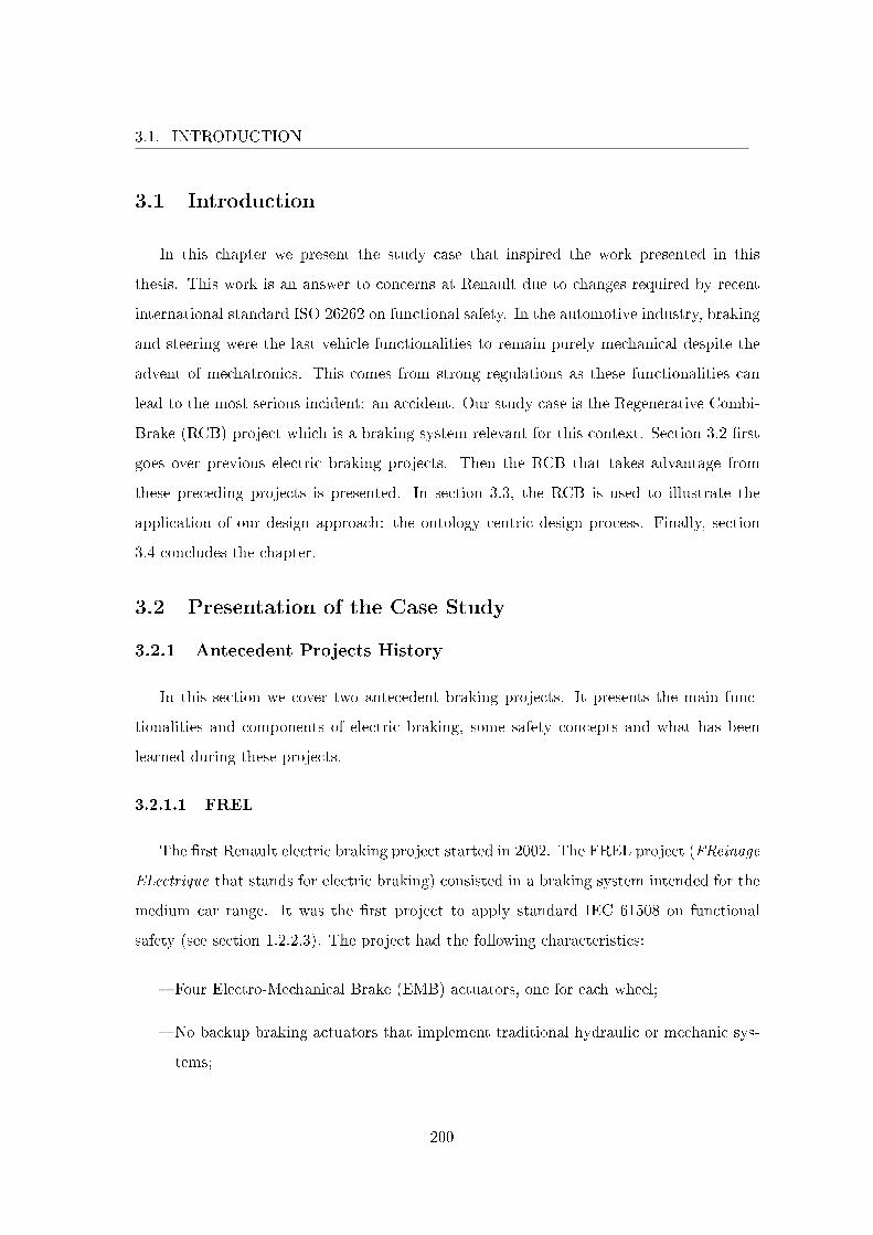
3.1. INTRODUCTION
3.1 Introduction
In this chapter we present the study case that inspired the work presented in this
thesis. This work is an answer to concerns at Renault due to changes required by recent
international standard ISO 26262 on functional safety. In the automotive industry, braking
and steering were the last vehicle functionalities to remain purely mechanical despite the
advent of mechatronics. This comes from strong regulations as these functionalities can
lead to the most serious incident: an accident. Our study case is the Regenerative Combi-
Brake (RCB) project which is a braking system relevant for this context. Section 3.2 �rst
goes over previous electric braking projects. Then the RCB that takes advantage from
these preceding projects is presented. In section 3.3, the RCB is used to illustrate the
application of our design approach: the ontology centric design process. Finally, section
3.4 concludes the chapter.
3.2 Presentation of the Case Study
3.2.1 Antecedent Projects History
In this section we cover two antecedent braking projects. It presents the main func-
tionalities and components of electric braking, some safety concepts and what has been
learned during these projects.
3.2.1.1 FREL
The �rst Renault electric braking project started in 2002. The FREL project (FReinage
ELectrique that stands for electric braking) consisted in a braking system intended for the
medium car range. It was the �rst project to apply standard IEC 61508 on functional
safety (see section 1.2.2.3). The project had the following characteristics:
� Four Electro-Mechanical Brake (EMB) actuators, one for each wheel;
� No backup braking actuators that implement traditional hydraulic or mechanic sys-
tems;
200
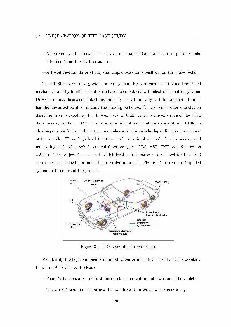
3.2. PRESENTATION OF THE CASE STUDY
� No mechanical link between the driver's commands (i.e., brake pedal or parking brake
interfaces) and the EMB actuators;
� A Pedal Feel Emulator (PFE) that implements force feedback on the brake pedal.
The FREL system is a by-wire braking system. By-wire means that some traditional
mechanical and hydraulic control parts have been replaced with electronic control systems.
Driver's commands are not linked mechanically or hydraulically with braking actuators. It
has the unwanted result of making the braking pedal soft (i.e., absence of force feedback)
disabling driver's capability for di�erent level of braking. Thus the existence of the PFE.
As a braking system, FREL has to ensure an optimum vehicle deceleration. FREL is
also responsible for immobilization and release of the vehicle depending on the context
of the vehicle. Those high level functions had to be implemented while preserving and
interacting with other vehicle control functions (e.g., ABS, ASR, ESP, etc. See section
3.2.2.2). The project focused on the high-level control software developed for the EMB
control system following a model-based design approach. Figure 3.1 presents a simpli�ed
system architecture of the project.
Figure 3.1: FREL simpli�ed architecture
We identify the key components required to perform the high level functions decelera-
tion, immobilization and release:
� Four EMBs that are used both for deceleration and immobilization of the vehicle;
� The driver's command interfaces for the driver to interact with the system;
201
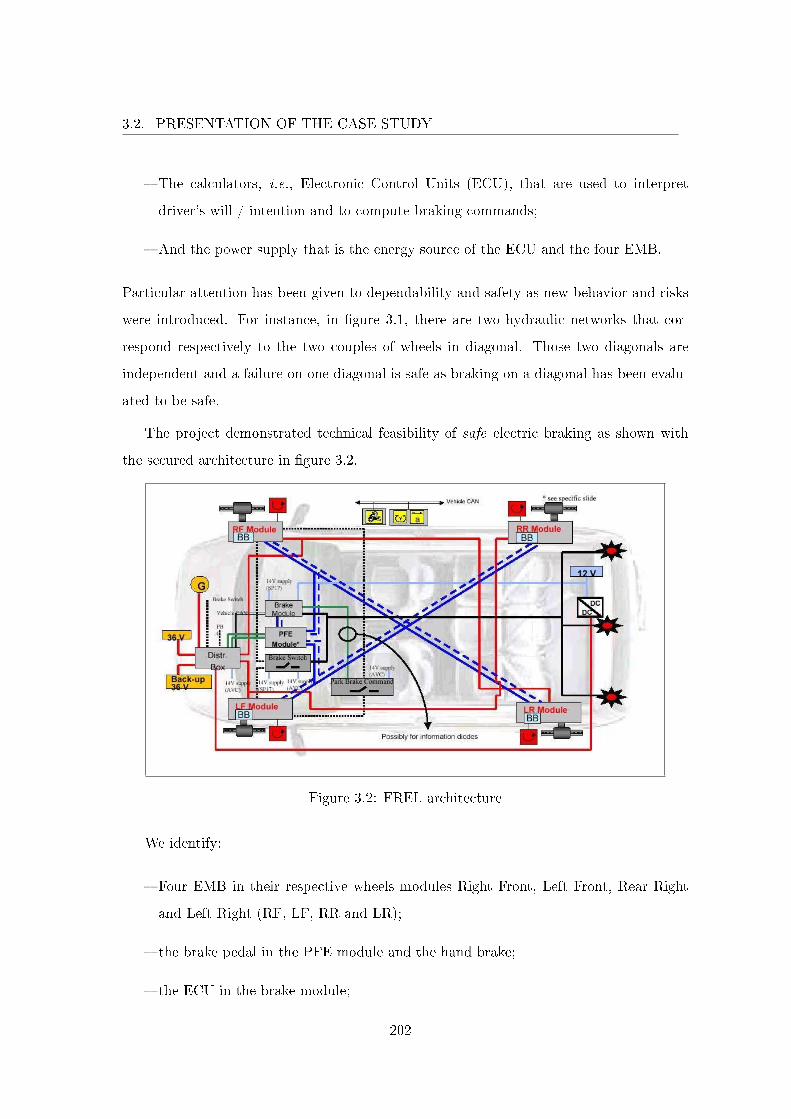
3.2. PRESENTATION OF THE CASE STUDY
� The calculators, i.e., Electronic Control Units (ECU), that are used to interpret
driver's will / intention and to compute braking commands;
� And the power supply that is the energy source of the ECU and the four EMB.
Particular attention has been given to dependability and safety as new behavior and risks
were introduced. For instance, in �gure 3.1, there are two hydraulic networks that cor-
respond respectively to the two couples of wheels in diagonal. Those two diagonals are
independent and a failure on one diagonal is safe as braking on a diagonal has been evalu-
ated to be safe.
The project demonstrated technical feasibility of safe electric braking as shown with
the secured architecture in �gure 3.2.
Figure 3.2: FREL architecture
We identify:
� Four EMB in their respective wheels modules Right Front, Left Front, Rear Right
and Left Right (RF, LF, RR and LR);
� the brake pedal in the PFE module and the hand brake;
� the ECU in the brake module;
202
3.2. PRESENTATION OF THE CASE STUDY
� the power supply (36V) that has been moved to the front;
� And the diagonal architecture that makes possible to brake independently on the
four wheels.
The hydraulic network has been completely gotten rid o� and the link between braking
interfaces and the braking system is by-wire. As a result, the brake pedal is hidden inside
a PFE module and a data �ow network (the blue straight and dashed lines) replaces the
hydraulic network with the same diagonal architecture. The whole system power source
is redundant with a backup power supply (Backup 36V) for the four EMB and another
battery (12V) that backs up the brake module.
Safety design choices are implicit as shown in �gure 3.2. Important aftermath in subse-
quents projects lies in the choice of a braking command. Di�erent braking functions may
run simultaneously and ask for di�erent braking services. Commands priority has been
de�ned to always select the most adequate one.
In addition to those architectural choices, FREL has been developed to exhibit the
following properties:
� The system shall ensure a minimum deceleration of the vehicle in case of a failure
that a�ects the deceleration on four wheels functionality
� The system shall not display undesired braking action (i.e., braking action without
a demand from the driver)
� The system shall ensure that a driver's (braking) request implies a braking action
� The system shall be fail silent (i.e., no error propagation)
� The system shall ensure that immobilizing failures are limited to less than 5%
We won't go into any further details on the FREL project. The project ran until the
end of 2003 and concluded on the extra costs of the technology to be too expensive for
relatively small braking service and safety gains.
203
3.2. PRESENTATION OF THE CASE STUDY
3.2.1.2 X by Wire.
The preceding by-wire project FREL concluded on the extra costs of the technology
(i.e., by-wire technology) not to be a�ordable. Mainly, costs came from the necessity to
secure the architecture thus the idea to level o� the costs by gathering all the by-wire
systems and searching for services at the inter-system level, idea that materialized in the
X by Wire project.
The project "Commandes Découplées", that is French for X by Wire (XbW), the X
stands for the multiple functions, has been initiated in mid-2004. The objective was to
prepare the company to the introduction of electric commands (i.e., by-wire) for braking
and steering functions inside Renault lines/�eet. Those two functions are the last functions
at vehicle level that have kept full mechanic or hydraulic parts as they are intimately related
to safety. Introduction of by-wire technology seemed inevitable at the time therefore the
two objectives of the project were:
� To �nd customer services that one customer will �nd acceptable compared to the
cost of the vehicle;
� To construct the development process adapted to such safety critical systems.
Over the course of the development, the project has gone through di�erent phases.
The project has focused on steering and braking functions, �rst as a whole, and then
separately. The respective systems denominations have been used: Steer and Brake by
Wire (SBbW) which was the �rst project that intended to apply systems engineering, Steer
by Wire (SbW) and Brake by Wire (BbW). SbW and BbW systems make for all necessary
and su�cient functions of steering and braking. However, their interconnection enables
the introduction of new services (such as regenerative braking, lane keeping, automatic
cruise control, etc.) by means of software blocs and, if necessary, by adding sensors,
thus SBbW system that takes SbW and BbW considerations at a more abstract level.
Implementation of new functionalities result in an increase in system complexity (i.e.,
introduction of hardware components). From the beginning, XbW system disposes of all
hardware components that enable most of the services that will be depicted in section 3.2.2.
204
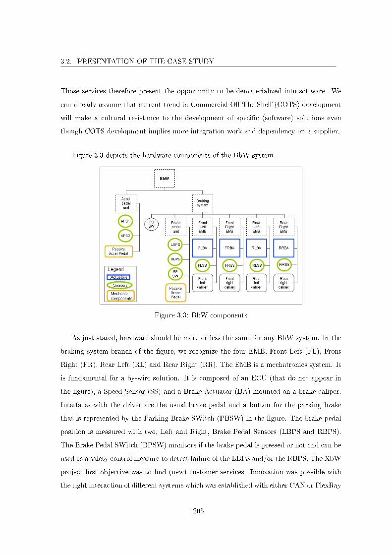
3.2. PRESENTATION OF THE CASE STUDY
Those services therefore present the opportunity to be dematerialized into software. We
can already assume that current trend in Commercial O� The Shelf (COTS) development
will make a cultural resistance to the development of speci�c (software) solutions even
though COTS development implies more integration work and dependency on a supplier.
Figure 3.3 depicts the hardware components of the BbW system.
Figure 3.3: BbW components
As just stated, hardware should be more or less the same for any BbW system. In the
braking system branch of the �gure, we recognize the four EMB, Front Left (FL), Front
Right (FR), Rear Left (RL) and Rear Right (RR). The EMB is a mechatronics system. It
is fundamental for a by-wire solution. It is composed of an ECU (that do not appear in
the �gure), a Speed Sensor (SS) and a Brake Actuator (BA) mounted on a brake caliper.
Interfaces with the driver are the usual brake pedal and a button for the parking brake
that is represented by the Parking Brake SWitch (PBSW) in the �gure. The brake pedal
position is measured with two, Left and Right, Brake Pedal Sensors (LBPS and RBPS).
The Brake Pedal SWitch (BPSW) monitors if the brake pedal is pressed or not and can be
used as a safety control measure to detect failure of the LBPS and/or the RBPS. The XbW
project �rst objective was to �nd (new) customer services. Innovation was possible with
the tight interaction of di�erent systems which was established with either CAN or FlexRay
205
3.2. PRESENTATION OF THE CASE STUDY
communication systems. As such, the BbW project perimeter integrated the Accelerator
Pedal Unit (Accel Pedal Unit). This unit is composed of the driver's accelerator pedal
interface and two sensors, Accelerator Pedal Sensor 1 and 2 (APS1 and APS2).
The inclusion of the accelerator enables to o�er new services for advanced braking
strategies. For instance, BbW can detect an emergency reaction of the driver and activate
the emergency braking service. The scenario is the following: the driver goes quickly from
the accelerator to the brake pedal in response to an emergency. First, the system detects
a quick release of the accelerator and engage the brakes by itself. Then second, the driver
wants to brake and starts to push the brake pedal. The system detects a rapid change
from the accelerator to the brake pedal which corresponds to an emergency, it activates
the emergency braking service which applies the maximum braking force until Anti Block
System regulation. Other strategies have been developed that bene�t from the system
external environment. In the previous example, we had to introduce new sensors on the
brake pedal. The system can also make use of existing components making the notion of
new virtual service.
The project stopped in January 2008. The reasons that were mentioned pointed out
interests divergence between di�erent departments at the company level. For instance, prof-
itability studies did not show that the company would break even and product marketing
considered that the economical balance with regards to the services would be understood
only by specialists and therefore was not viable. Moreover, the project met internal neg-
ativism from the engine department which considered the project fruitless as it did not
bring radical change in the architecture, the product remaining more or less the same,
whereas the improvement was for the development method to be adapted to safety critical
systems. More generally, downstream directions did not involve themselves su�ciently for
the project to be transfered into Renault vehicles �eet.
Nevertheless, the project was highly pro�cient. The objectives were met. On new
services or innovations, by March 2008, the project had generated a total of 140 patents
in France that were the source for more innovations (24 other patents referenced patents
from the project). Two prototypes implementing BbW were developed and helped in the
206
3.2. PRESENTATION OF THE CASE STUDY
realization of braking command laws adapted to independent braking on the four wheels.
On the construction of a development process, the project enabled all the Renault actors to
tightly work together in a cohesive manner, thus identifying new roles that were inexistent
(for instance system engineer) and what activities each actor was responsible for. The
project concluded that the development of safety critical systems requires the automobile
constructor to position itself as a system developer rather than an integrator of commercial
solutions (e.g., COTS) that are not completely mastered and that the company is liable
for. Important results on the development of safety critical systems therefore came from
systems engineering and international standard ISO 26262 that are respectively treated in
sections 1.2.1 and 1.2.2.3.
3.2.2 A Regenerative Combi-Brake System
3.2.2.1 Towards an Electric Vehicle
By the end of 2008, the automotive industry has been strongly a�ected by the crisis
that occurred starting from the �nancial world. The situation led the direction board of
Renault to take radical decisions in order to better position the company for a world in
mutation. We can mention two decisions that are important for this section. First, the
concentration of the engineering e�ort over a full electric vehicle (i.e., equipped with an
electric engine). That is the Electric Vehicle (EV) project. Second, the a�rmation of a
new identity with the company signature "Drive the change".
The EV project started in 2008. EV is a vehicle project. Under systems engineering
vocabulary, the system (under development) is the whole vehicle. It is a �rst on many
points. It is the �rst vehicle with an electric engine developed internally to be included in
Renault line/�eet. It is the �rst project onto which systems engineering method has been
applied at the vehicle level. It is the �rst vehicle project onto which standard ISO 26262
(see section 1.2.2.3) has been applied.
EV project comes from the desire of the company to drive the change in bringing
an a�ordable electric vehicle on the market (i.e., with a selling price equivalent to the
one of a fuel motorized vehicle of the same category). As the project calls for originality
(by developing an electric engine), new risks are also introduced. The automobile world
207
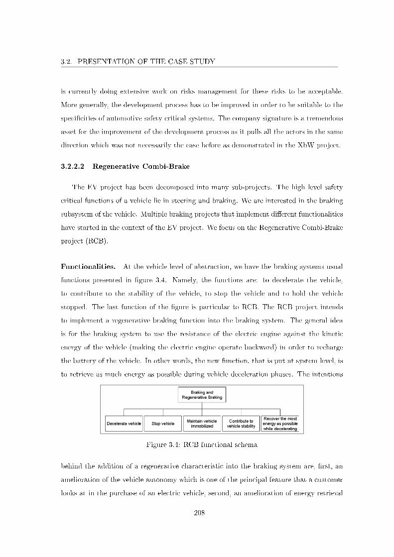
3.2. PRESENTATION OF THE CASE STUDY
is currently doing extensive work on risks management for these risks to be acceptable.
More generally, the development process has to be improved in order to be suitable to the
speci�cities of automotive safety critical systems. The company signature is a tremendous
asset for the improvement of the development process as it pulls all the actors in the same
direction which was not necessarily the case before as demonstrated in the XbW project.
3.2.2.2 Regenerative Combi-Brake
The EV project has been decomposed into many sub-projects. The high level safety
critical functions of a vehicle lie in steering and braking. We are interested in the braking
subsystem of the vehicle. Multiple braking projects that implement di�erent functionalities
have started in the context of the EV project. We focus on the Regenerative Combi-Brake
project (RCB).
Functionalities. At the vehicle level of abstraction, we have the braking systems usual
functions presented in �gure 3.4. Namely, the functions are: to decelerate the vehicle,
to contribute to the stability of the vehicle, to stop the vehicle and to hold the vehicle
stopped. The last function of the �gure is particular to RCB. The RCB project intends
to implement a regenerative braking function into the braking system. The general idea
is for the braking system to use the resistance of the electric engine against the kinetic
energy of the vehicle (making the electric engine operate backward) in order to recharge
the battery of the vehicle. In other words, the new function, that is put at system level, is
to retrieve as much energy as possible during vehicle deceleration phases. The intentions
Figure 3.4: RCB functional schema
behind the addition of a regenerative characteristic into the braking system are, �rst, an
amelioration of the vehicle autonomy which is one of the principal feature that a customer
looks at in the purchase of an electric vehicle, second, an amelioration of energy retrieval
208
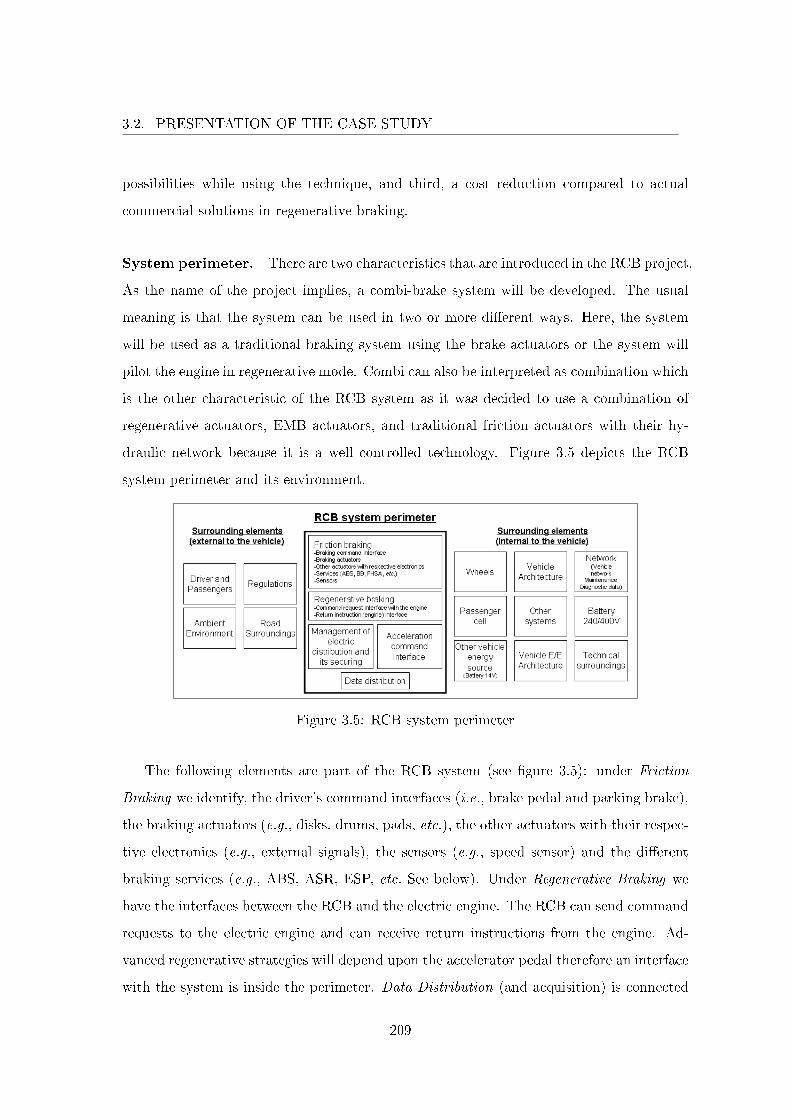
3.2. PRESENTATION OF THE CASE STUDY
possibilities while using the technique, and third, a cost reduction compared to actual
commercial solutions in regenerative braking.
System perimeter. There are two characteristics that are introduced in the RCB project.
As the name of the project implies, a combi-brake system will be developed. The usual
meaning is that the system can be used in two or more di�erent ways. Here, the system
will be used as a traditional braking system using the brake actuators or the system will
pilot the engine in regenerative mode. Combi can also be interpreted as combination which
is the other characteristic of the RCB system as it was decided to use a combination of
regenerative actuators, EMB actuators, and traditional friction actuators with their hy-
draulic network because it is a well controlled technology. Figure 3.5 depicts the RCB
system perimeter and its environment.
Figure 3.5: RCB system perimeter
The following elements are part of the RCB system (see �gure 3.5): under Friction
Braking we identify, the driver's command interfaces (i.e., brake pedal and parking brake),
the braking actuators (e.g., disks, drums, pads, etc.), the other actuators with their respec-
tive electronics (e.g., external signals), the sensors (e.g., speed sensor) and the di�erent
braking services (e.g., ABS, ASR, ESP, etc. See below). Under Regenerative Braking we
have the interfaces between the RCB and the electric engine. The RCB can send command
requests to the electric engine and can receive return instructions from the engine. Ad-
vanced regenerative strategies will depend upon the accelerator pedal therefore an interface
with the system is inside the perimeter. Data Distribution (and acquisition) is connected
209
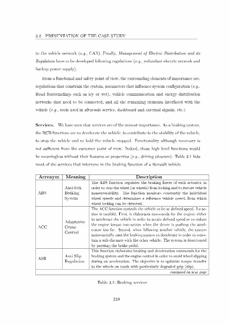
3.2. PRESENTATION OF THE CASE STUDY
to the vehicle network (e.g., CAN). Finally, Management of Electric Distribution and its
Regulation have to be developed following regulations (e.g., redundant electric network and
backup power supply).
From a functional and safety point of view, the surrounding elements of importance are,
regulations that constrain the system, parameters that in�uence system con�guration (e.g.,
Road Surroundings such as icy or wet), vehicle communication and energy distribution
networks that need to be connected, and all the remaining elements interfaced with the
vehicle (e.g., tools used in after-sale service, dashboard and external signals, etc.).
Services. We have seen that services are of the utmost importance. As a braking system,
the RCB functions are to decelerate the vehicle, to contribute to the stability of the vehicle,
to stop the vehicle and to hold the vehicle stopped. Functionality although necessary is
not su�cient from the customer point of view. Indeed, those high level functions would
be meaningless without their features or properties (e.g., driving pleasure). Table 3.1 lists
most of the services that intervene in the braking function of a Renault vehicle.
Acronym Meaning Description
ABSAnti-lockBrakingSystem
The ABS function regulates the braking forces of each actuator in
order to stop the wheel (or wheels) from locking and to restore vehicle
maneuverability. The function monitors constantly the individual
wheel speeds and determines a reference vehicle speed, from which
wheel locking can be detected.
ACCAdaptativeCruiseControl
The ACC function controls the vehicle to be at de�ned speed. Its ac-
tion is twofold. First, it elaborates commands for the engine; either
to accelerate the vehicle in order to attain de�ned speed or to reduce
the engine torque instruction when the driver is pushing the accel-
erator too far. Second, when following another vehicle, the system
automatically uses the braking system to decelerate in order to main-
tain a safe distance with the other vehicle. The system is deactivated
by pressing the brake pedal.
ASRAnti-SlipRegulation
This function elaborates braking and deceleration commands for the
braking system and the engine control in order to avoid wheel slipping
during an acceleration. The objective is to optimize torque transfer
to the wheels on roads with particularly degraded grip (slip).
continued on next page
Table 3.1: Braking services
210
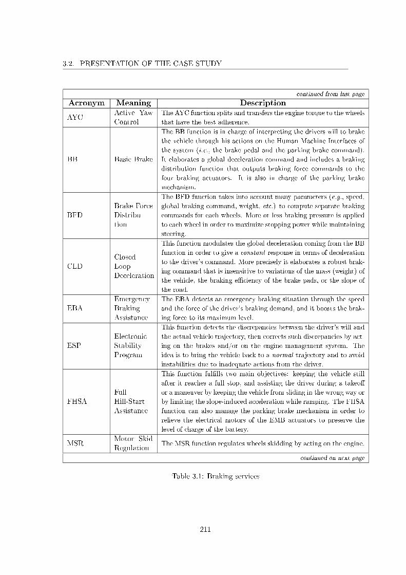
3.2. PRESENTATION OF THE CASE STUDY
continued from last page
Acronym Meaning Description
AYCActive YawControl
The AYC function splits and transfers the engine torque to the wheels
that have the best adherence.
BB Basic Brake
The BB function is in charge of interpreting the drivers will to brake
the vehicle through his actions on the Human Machine Interfaces of
the system (i.e., the brake pedal and the parking brake command).
It elaborates a global deceleration command and includes a braking
distribution function that outputs braking force commands to the
four braking actuators. It is also in charge of the parking brake
mechanism.
BFDBrake ForceDistribu-tion
The BFD function takes into account many parameters (e.g., speed,
global braking command, weight, etc.) to compute separate braking
commands for each wheels. More or less braking pressure is applied
to each wheel in order to maximize stopping power while maintaining
steering.
CLDClosedLoopDeceleration
This function modulates the global deceleration coming from the BB
function in order to give a constant response in terms of deceleration
to the driver's command. More precisely it elaborates a robust brak-
ing command that is insensitive to variations of the mass (weight) of
the vehicle, the braking e�ciency of the brake pads, or the slope of
the road.
EBAEmergencyBrakingAssistance
The EBA detects an emergency braking situation through the speed
and the force of the driver's braking demand, and it boosts the brak-
ing force to its maximum level.
ESPElectronicStabilityProgram
This function detects the discrepancies between the driver's will and
the actual vehicle trajectory, then corrects such discrepancies by act-
ing on the brakes and/or on the engine management system. The
idea is to bring the vehicle back to a normal trajectory and to avoid
instabilities due to inadequate actions from the driver.
FHSAFullHill-StartAssistance
This function ful�lls two main objectives: keeping the vehicle still
after it reaches a full stop, and assisting the driver during a takeo�
or a maneuver by keeping the vehicle from sliding in the wrong way or
by limiting the slope-induced acceleration while ramping. The FHSA
function can also manage the parking brake mechanism in order to
relieve the electrical motors of the EMB actuators to preserve the
level of charge of the battery.
MSRMotor SkidRegulation
The MSR function regulates wheels skidding by acting on the engine.
continued on next page
Table 3.1: Braking services
211
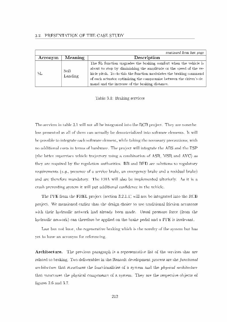
3.2. PRESENTATION OF THE CASE STUDY
continued from last page
Acronym Meaning Description
SLSoftLanding
The SL function upgrades the braking comfort when the vehicle is
about to stop by diminishing the amplitude or the speed of the ve-
hicle pitch. To do this the function modulates the braking command
of each actuator optimizing the compromise between the driver's de-
mand and the increase of the braking distance.
Table 3.1: Braking services
The services in table 3.1 will not all be integrated into the RCB project. They are nonethe-
less presented as all of them can actually be dematerialized into software elements. It will
be possible to integrate each software element, while taking the necessary precautions, with
no additional costs in terms of hardware. The project will integrate the ABS and the ESP
(the latter supervises vehicle trajectory using a combination of ASR, MSR and AYC) as
they are required by the regulation authorities. BB and BFD are solutions to regulatory
requirements (e.g., presence of a service brake, an emergency brake and a residual brake)
and are therefore mandatory. The EBA will also be implemented ulteriorly. As it is a
crash preventing system it will put additional con�dence in the vehicle.
The PFE from the FREL project (section 3.2.1.1) will not be integrated into the RCB
project. We mentioned earlier that the design choice to use traditional friction actuators
with their hydraulic network had already been made. Usual pressure force (from the
hydraulic network) can therefore be applied on the brake pedal and a PFE is irrelevant.
Last but not least, the regenerative braking which is the novelty of the system but has
yet to have an acronym for referencing.
Architecture. The previous paragraph is a representative list of the services that are
related to braking. Two deliverables in the Renault development process are the functional
architecture that structures the functionalities of a system and the physical architecture
that structures the physical components of a system. They are the respective objects of
�gures 3.6 and 3.7.
212
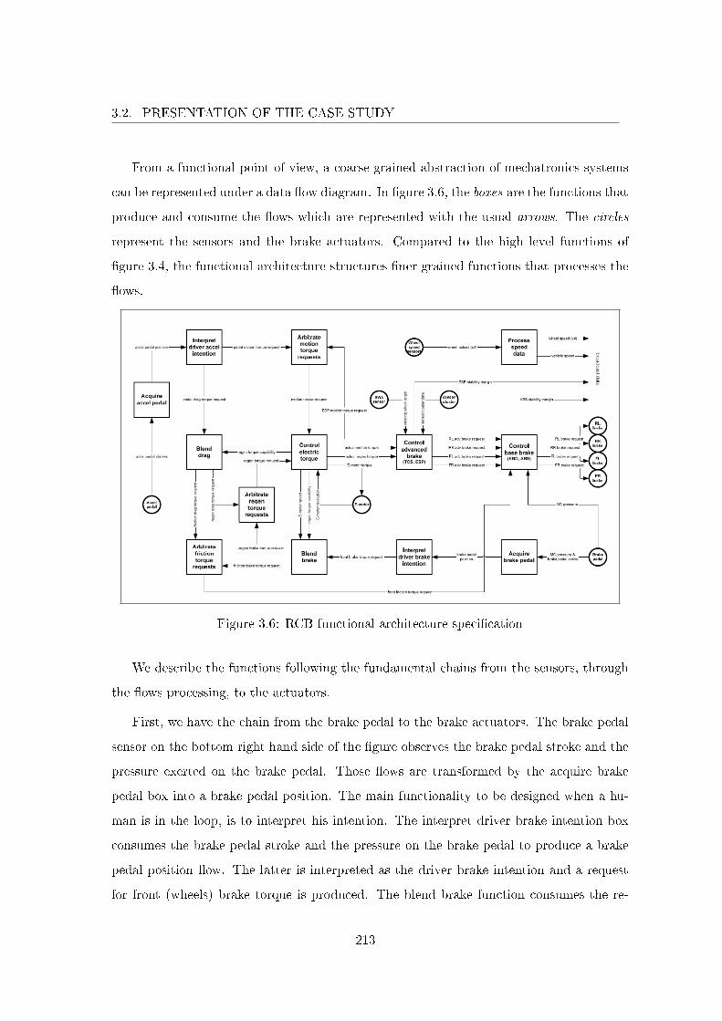
3.2. PRESENTATION OF THE CASE STUDY
From a functional point of view, a coarse grained abstraction of mechatronics systems
can be represented under a data �ow diagram. In �gure 3.6, the boxes are the functions that
produce and consume the �ows which are represented with the usual arrows. The circles
represent the sensors and the brake actuators. Compared to the high level functions of
�gure 3.4, the functional architecture structures �ner grained functions that processes the
�ows.
Figure 3.6: RCB functional architecture speci�cation
We describe the functions following the fundamental chains from the sensors, through
the �ows processing, to the actuators.
First, we have the chain from the brake pedal to the brake actuators. The brake pedal
sensor on the bottom right hand side of the �gure observes the brake pedal stroke and the
pressure exerted on the brake pedal. Those �ows are transformed by the acquire brake
pedal box into a brake pedal position. The main functionality to be designed when a hu-
man is in the loop, is to interpret his intention. The interpret driver brake intention box
consumes the brake pedal stroke and the pressure on the brake pedal to produce a brake
pedal position �ow. The latter is interpreted as the driver brake intention and a request
for front (wheels) brake torque is produced. The blend brake function consumes the re-
213

3.2. PRESENTATION OF THE CASE STUDY
generative torque capability, the electric motor speed and the precedent front brake torque
request. The function produces two requests for the friction brake and the regenerative
brake respectively. Those two �ows are then arbitrated to produce a front friction torque
request and a regenerative brake torque request respectively. The request on regenerative
torque is consumed by the o�-system controller that is responsible for the electric motor
torque, controller that commands the electric motor brake actuator. Meanwhile, the front
friction torque request goes to the base brake controller which is responsible for services
such as the BFD and the ABS. Finally, the controller assign brake requests on the four
wheels brakes.
Second, we have the chain from the accelerator pedal to the brake actuators. The
accelerator pedal sensor is on the left side of the �gure. From there we have the same
functions than before: acquire the accelerator pedal that produces the accelerator pedal
position and interpret driver acceleration intention that produces two requests for the
electric motor, one for (positive) motion the other for drag (i.e., negative motion). On
the one side, the request for (positive) motion is o�-system and shown only because of
tight interconnection with the ESP that can request another motion torque. The arbitrate
motion torque requests function produces a motion torque request to the controller of
electric torque which commands the electric motor. On the other side, the pedal drag
torque request is consumed with the regenerative torque capability �ow by the blend drag
function that produces two torque requests for the friction brake and the regenerative
brake respectively. The rest of the chain is similar to the �rst one: Those two �ows
are arbitrated to produce a front friction torque request and a regenerative brake torque
request respectively. The request on regenerative torque is consumed by the electric motor
controller that commands the electric motor brake actuator. Meanwhile, the front friction
torque request goes to the base brake controller that assigns brake requests on the four
wheels brakes.
It remains two functions on the �gure: control advanced brake and process speed data.
The latter digitalizes the vehicle (global) speed and the four wheel speeds. On the control
advanced brake, it can be interesting to introduce the notion of a virtual driver as the
function emulates the reactions of a driver. The function consumes many parameters that
214
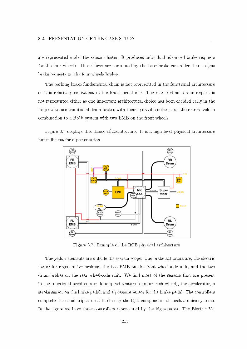
3.2. PRESENTATION OF THE CASE STUDY
are represented under the sensor cluster. It produces individual advanced brake requests
for the four wheels. Those �ows are consumed by the base brake controller that assigns
brake requests on the four wheels brakes.
The parking brake fundamental chain is not represented in the functional architecture
as it is relatively equivalent to the brake pedal one. The rear friction torque request is
not represented either as one important architectural choice has been decided early in the
project: to use traditional drum brakes with their hydraulic network on the rear wheels in
combination to a BbW system with two EMB on the front wheels.
Figure 3.7 displays this choice of architecture. It is a high level physical architecture
but su�cient for a presentation.
Figure 3.7: Example of the RCB physical architecture
The yellow elements are outside the system scope. The brake actuators are, the electric
motor for regenerative braking, the two EMB on the front wheel-axle unit, and the two
drum brakes on the rear wheel-axle unit. We �nd most of the sensors that are present
in the functional architecture: four speed sensors (one for each wheel), the accelerator, a
stroke sensor on the brake pedal, and a pressure sensor for the brake pedal. The controllers
complete the usual triplet used to classify the E/E components of mechatronics systems.
In the �gure we have three controllers represented by the big squares. The Electric Ve-
215

3.2. PRESENTATION OF THE CASE STUDY
hicle Controller (EVC) serves mainly to control the electric engine and is o�-system but
important for interconnection purpose. The MKXXA is responsible for the usual braking
functions of a braking system: to decelerate the vehicle, to contribute to the vehicle sta-
bility, to stop the vehicle and to hold the vehicle stopped. Even more, it is responsible for
providing all the services presented before. As for the supervisor, it is responsible to the
last function of the RCB, to recover the most energy as possible while decelerating.
An E/E system is dependent on a power source (which is outside the scope of the
RCB system). There are two batteries that for technological reason are necessary (e.g.,
cell management requires a redundant cell con�guration). The main battery powers the
calculators and the two EMB. It is represented with red lines in the �gure. As for the High
Voltage (HV) battery, it is tightly interconnected to the system therefore the part of interest
is the communication network. The communication network is represented with straight
black lines. The only elements that appear not related in any way to the communication
network are the drum brakes on the rear end of the vehicle and the main battery. Except
for those, all the elements are interconnected with CAN links. Finally, the big black lines
represent the hydraulic network that links the rear drum brakes and the brake pedal.
One last thing about typical components of E/E systems, the EMB is a COTS. Inciden-
tally, it is not dimensioned speci�cally for the RCB project and houses in a controller and
a speed sensor which is not used at the time but will probably be identi�ed as a fundamen-
tal part of the system later in the development. More generally, automobile constructors
heavily relies on parts suppliers. In the RCB project, Continental has been selected to
develop the system. Renault actors were in charge to deliver requirements to Continental's
actors. Continental is then in charge of the development and the realization of the product.
It was also decided that Continental was in charge of the safety studies. Once the product
will be delivered, Renault will have to verify and validate that the product conforms to the
given requirements and make an integration e�ort in order to use the product in a vehicle.
The fundamental importance of the requirements is transparent as they have to convey the
constructor intentions for the supplier to realize a good product and they are used for the
product veri�cation, validation and integration. Furthermore, the supplier often delivers a
product for which only black box knowledge is known about, resulting in di�culties to es-
216
3.2. PRESENTATION OF THE CASE STUDY
timate the relevance of the solution. Therefore, requirements need to be veri�able, precise
and complete. This is especially the case when safety is concerned. Consider the case of a
faulty product from a supplier that leads to an accident; it is not the supplier that will be
accountable for the accident but the constructor.
This physical architecture must implement all the functions from the functional archi-
tecture. Thereby it is one among the many possible physical architectures. Obviously,
the physical architecture in �gure 3.7 is not a haphazard choice. One can argue that the
combi-brake solution is more complex than a solution that does not mix technologies but
here are some justi�cations that make a good compromise on complexity, safety and costs.
First, the FREL project mapped the braking service that was provided by the use of any
combination of the four wheels. There is less degrees of freedom in the RCB project as one
can brake using a combination of the three braking subsystems: the front wheel-axle unit,
the rear wheel-axle unit and the regenerative brake. The system is thus easier to analyze
even when it comes to safety. In fact, three types of braking systems are mandatory: a
service brake used in normal driving conditions, an emergency brake (or secondary brake)
for use in case of failure of the service brake, and a residual brake that is operational
even in the case of a power failure. The decomposition is obvious, the service brake is
ensured by all the braking subsystems, the emergency brake is ensured by the traditional
rear wheel-axle unit, and the residual brake is also part of the rear wheel-axle unit which
is usual.
Second, the choice to use drum brakes on the rear wheel-axle unit greatly simpli�es the
system analysis as it is a well controlled technology. For instance, it enables to get rid of the
PFE from antecedent projects by taking advantage of the hydraulic network of the drum
brake technology. It su�ces to increase the distance between the drums and the brake
pads in such a manner that light braking will not make the drum and the pads contact
resulting in braking on the regenerative brake or/and the front wheel-axle unit only. The
force feedback on the brake pedal is ensured by the retracting springs of the drum pads.
This solution contributes to recover the most energy as possible by promoting regenerative
braking over the other brakings. Moreover, the combi-brake solution answers the regulation
217
3.3. APPLICATION OF THE APPROACH
requirement to have an emergency brake independent with the service brake by treating
the front and rear wheel-axle units separately. This architectural separation facilitates
the demonstration that the two brakes are independent. Even more, drum brakes are not
subject to the permanent energy leakage of the disk brake technology that is due to a light
brush of the pads on the disk for self cleansing. Finally, drum brakes present the advantage
(even though they o�er less precise braking than disk brakes) to be auto-amplifying. It
is a desirable property as the drum brakes will be used mostly in hard braking situations
where the maximum braking e�ort must be reached as fast as possible.
The result is an elegant solution that is highly compartmentalized enabling to analyze
the system by components of smaller size.
3.2.3 Conclusion
As we said in section 3.2.2.2, braking and steering functions are safety critical. The RCB
project that develops a regenerative braking system illustrates the current state of a�air
inside Renault. As such, this section should be taken as an example and be generalized
to Renault's mechatronics systems. This section helped to characterize three points. One,
Renault's role when developing critical systems as a developer of systems rather than an
integrator of commercial solutions. Two, the particular relation between a constructor and
a supplier. Three, the increasing system's complexity due to mechatronics considerations
of multiple domains and the resulting introduction of new risks. De�ning a development
process for mechatronics systems that takes into account Renault speci�cities and that
is conform to ISO 26262 was the objective of this work. The next section presents the
application of our approach on the RCB system.
3.3 Application of the Approach
In this section we present the application of the approach from section 2.4.2 on the
RCB project. Actually, the approach based on an ontology was realized after the project.
Therefore documents and models do not always comply with the ontology. Nonetheless,
we had to anticipate for the formalized conceptualization to be general enough to consider
218
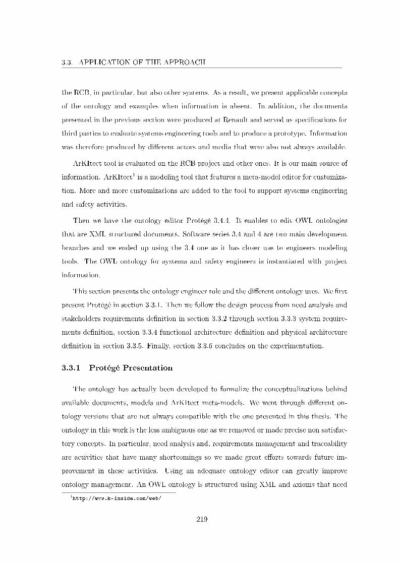
3.3. APPLICATION OF THE APPROACH
the RCB, in particular, but also other systems. As a result, we present applicable concepts
of the ontology and examples when information is absent. In addition, the documents
presented in the previous section were produced at Renault and served as speci�cations for
third parties to evaluate systems engineering tools and to produce a prototype. Information
was therefore produced by di�erent actors and media that were also not always available.
ArKItect tool is evaluated on the RCB project and other ones. It is our main source of
information. ArKItect1 is a modeling tool that features a meta-model editor for customiza-
tion. More and more customizations are added to the tool to support systems engineering
and safety activities.
Then we have the ontology editor Protégé 3.4.4. It enables to edit OWL ontologies
that are XML structured documents. Software series 3.4 and 4 are two main development
branches and we ended up using the 3.4 one as it has closer use to engineers modeling
tools. The OWL ontology for systems and safety engineers is instantiated with project
information.
This section presents the ontology engineer role and the di�erent ontology uses. We �rst
present Protégé in section 3.3.1. Then we follow the design process from need analysis and
stakeholders requirements de�nition in section 3.3.2 through section 3.3.3 system require-
ments de�nition, section 3.3.4 functional architecture de�nition and physical architecture
de�nition in section 3.3.5. Finally, section 3.3.6 concludes on the experimentation.
3.3.1 Protégé Presentation
The ontology has actually been developed to formalize the conceptualizations behind
available documents, models and ArKItect meta-models. We went through di�erent on-
tology versions that are not always compatible with the one presented in this thesis. The
ontology in this work is the less ambiguous one as we removed or made precise non satisfac-
tory concepts. In particular, need analysis and, requirements management and traceability
are activities that have many shortcomings so we made great e�orts towards future im-
provement in these activities. Using an adequate ontology editor can greatly improve
ontology management. An OWL ontology is structured using XML and axioms that need
1http://www.k-inside.com/web/
219
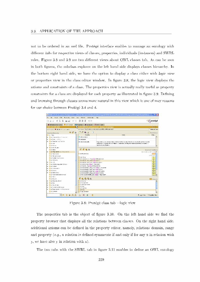
3.3. APPLICATION OF THE APPROACH
not to be ordered in an owl �le. Protégé interface enables to manage an ontology with
di�erent tabs for respective views of classes, properties, individuals (instances) and SWRL
rules. Figure 3.8 and 3.9 are two di�erent views about OWL classes tab. As can be seen
in both �gures, the subclass explorer on the left hand side displays classes hierarchy. In
the bottom right hand side, we have the option to display a class either with logic view
or properties view in the class editor window. In �gure 3.8, the logic view displays the
axioms and constraints of a class. The properties view is actually really useful as property
constraints for a class are displayed for each property as illustrated in �gure 3.9. De�ning
and browsing through classes seems more natural in this view which is one of may reasons
for our choice between Protégé 3.4 and 4.
Figure 3.8: Protégé class tab � logic view
The properties tab is the object of �gure 3.10. On the left hand side we �nd the
property browser that displays all the relations between classes. On the right hand side,
additional axioms can be de�ned in the property editor, namely, relations domain, range
and property (e.g., a relation is de�ned symmetric if and only if for any x in relation with
y, we have also y in relation with x).
The two tabs with the SWRL tab in �gure 3.11 enables to de�ne an OWL ontology
220
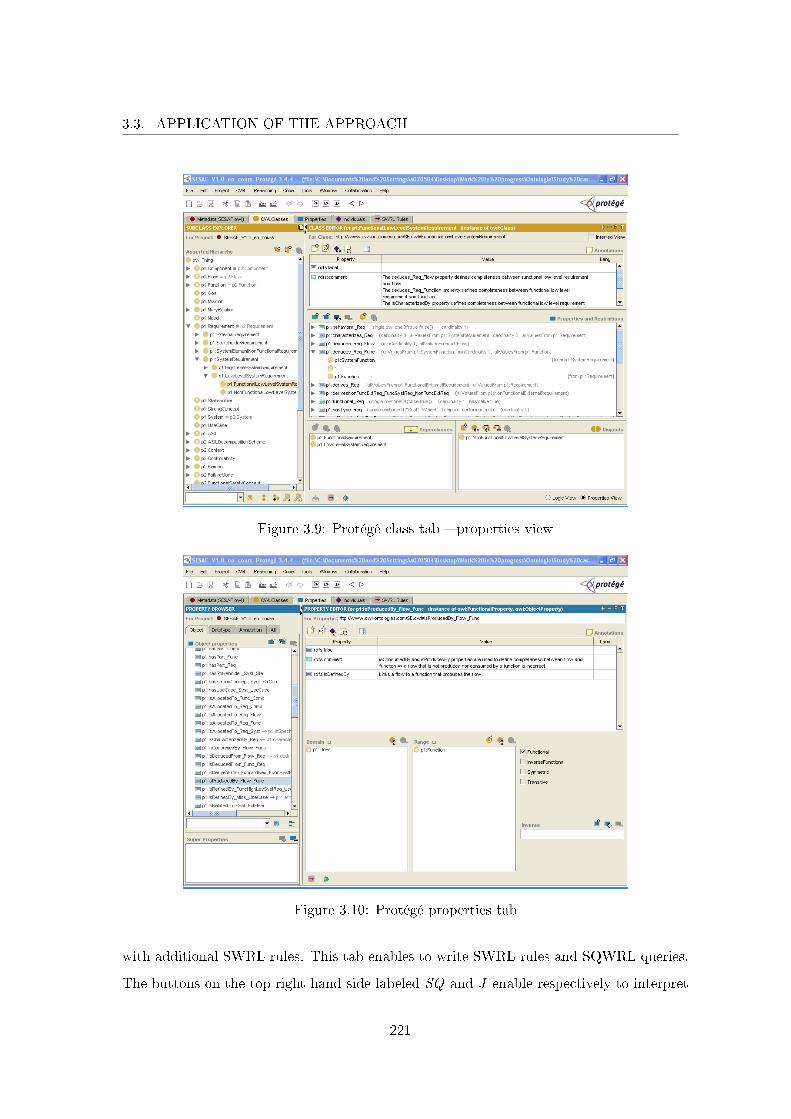
3.3. APPLICATION OF THE APPROACH
Figure 3.9: Protégé class tab � properties view
Figure 3.10: Protégé properties tab
with additional SWRL rules. This tab enables to write SWRL rules and SQWRL queries.
The buttons on the top right hand side labeled SQ and J enable respectively to interpret
221
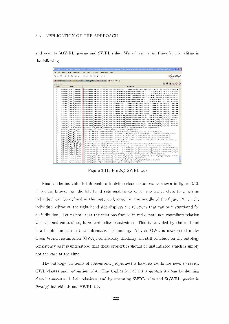
3.3. APPLICATION OF THE APPROACH
and execute SQWRL queries and SWRL rules. We will return on these functionalities in
the following.
Figure 3.11: Protégé SWRL tab
Finally, the individuals tab enables to de�ne class instances, as shown in �gure 3.12.
The class browser on the left hand side enables to select the active class to which an
individual can be de�ned in the instance browser in the middle of the �gure. Then the
individual editor on the right hand side displays the relations that can be instantiated for
an individual. Let us note that the relations framed in red denote non compliant relation
with de�ned constraints, here cardinality constraints. This is provided by the tool and
is a helpful indication that information is missing. Yet, as OWL is interpreted under
Open World Assumption (OWA), consistency checking will still conclude on the ontology
consistency as it is understood that these properties should be instantiated which is simply
not the case at the time.
The ontology (in terms of classes and properties) is �xed so we do not need to revisit
OWL classes and properties tabs. The application of the approach is done by de�ning
class instances and their relations, and by executing SWRL rules and SQWRL queries in
Protégé individuals and SWRL tabs.
222
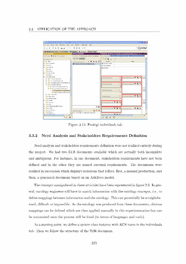
3.3. APPLICATION OF THE APPROACH
Figure 3.12: Protégé individuals tab
3.3.2 Need Analysis and Stakeholders Requirements De�nition
Need analysis and stakeholders requirements de�nition were not realized entirely during
the project. We had two STR documents available which are actually both incomplete
and ambiguous. For instance, in one document, stakeholders requirements have not been
de�ned and in the other they are named external requirements. The documents were
realized in succession which displays iterations that re�ect, �rst, a manual production, and
then, a generated document based on an ArKItect model.
The concepts manipulated in these activities have been represented in �gure 2.2. In gen-
eral, ontology engineers will have to match information with the ontology concepts, i.e., to
de�ne mappings between information and the ontology. This can potentially be straightfor-
ward, di�cult or impossible. As the ontology was produced from these documents, obvious
mappings can be de�ned which are then applied manually in this experimentation but can
be automated once the process will be �xed (in terms of languages and tools).
As a starting point, we de�ne a system class instance with RCB name in the individuals
tab. Then we follow the structure of the STR document.
223
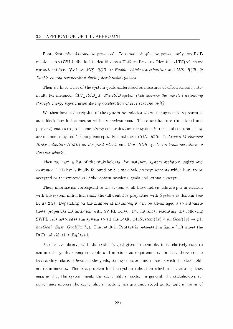
3.3. APPLICATION OF THE APPROACH
First, System's missions are presented. To remain simple, we present only two RCB
missions. An OWL individual is identi�ed by a Uniform Resource Identi�er (URI) which we
use as identi�ers. We have MIS_RCB_1: Enable vehicle's deceleration and MIS_RCB_2:
Enable energy regeneration during deceleration phases.
Then we have a list of the system goals understood as measures of e�ectiveness at Re-
nault. For instance: OBJ_RCB_1: The RCB system shall improve the vehicle's autonomy
through energy regeneration during deceleration phases (around 30%).
We then have a description of the system boundaries where the system is represented
as a black box in interaction with its environment. These architecture (functional and
physical) enable to pose some strong constraints on the system in terms of solution. They
are de�ned as system's strong concepts. For instance: CON_RCB_1: Electro-Mechanical
Brake actuators (EMB) on the front wheels and Con_RCB_4: Drum brake actuators on
the rear wheels.
Then we have a list of the stakeholders, for instance, system architect, safety and
customer. This list is �nally followed by the stakeholders requirements which have to be
accepted as the expression of the system missions, goals and strong concepts.
These information correspond to the system so all these individuals are put in relation
with the system individual using the di�erent has properties with System as domain (see
�gure 2.2). Depending on the number of instances, it can be advantageous to automate
these properties instantiation with SWRL rules. For instance, executing the following
SWRL rule associates the system to all the goals: p1:System(?x) ∧ p1:Goal(?y) → p1:
hasGoal_Syst_Goal(?x, ?y). The result in Protégé is presented in �gure 3.13 where the
RCB individual is displayed.
As one can observe with the system's goal given in example, it is relatively easy to
confuse the goals, strong concepts and missions as requirements. In fact, there are no
traceability relations between the goals, strong concepts and missions with the stakehold-
ers requirements. This is a problem for the system validation which is the activity that
ensures that the system meets the stakeholders needs. In general, the stakeholders re-
quirements express the stakeholders needs which are understood at Renault in terms of
224

3.3. APPLICATION OF THE APPROACH
Figure 3.13: RCB individual in Protégé
missions, goals and strong concepts and shall therefore be traced to corresponding stake-
holders requirements. As an example, we identi�ed that no stakeholders requirements was
de�ned for CON_RCB_1. The stakeholder need was nonetheless considered by a system
requirement which was questionable as it was not traced to a stakeholder requirement.
We have added these missing traceability relations in the ontology for additional coverage
analysis and the general Need concept for consideration.
Figure 3.14 corresponds to the stakeholders requirements view in ArKItect.
Rectangles with rounded corners represent stakeholders and the other rectangles con-
tained in the previous ones are stakeholders requirements of a speci�c stakeholder. This
corresponds to the boilerplate structure for stakeholders requirements: The <stakeholder
type> (shall or may) be able to <capability>. For instance: REQ_EXR_0001: The cus-
tomer shall be able to decelerate the vehicle. Intuitively, this stakeholder requirement ac-
tually comes from MIS_RCB_1: Enable vehicle's deceleration. In protégé, we can de�ne
this provenance by asserting the type (i.e., the class) of MIS_RCB_1 to p1:Need (i.e.,
MIS_RCB_1 is an instance of p1:Need) which enables to use p1:derives_Need_StaReq
225
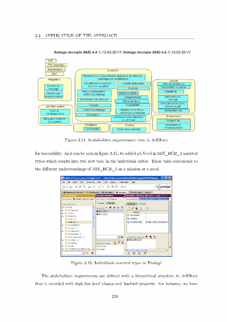
3.3. APPLICATION OF THE APPROACH
Figure 3.14: Stakeholders requirements view in ArKItect
for traceability. As it can be seen in �gure 3.15, we added p1:Need in MIS_RCB_1 asserted
types which results into two new tabs in the individual editor. These tabs correspond to
the di�erent understandings of MIS_RCB_1 as a mission or a need.
Figure 3.15: Individuals asserted types in Protégé
The stakeholders requirements are de�ned with a hierarchical structure in ArKItect
that is recorded with high/low level classes and hasPart property. For instance, we have
226
3.3. APPLICATION OF THE APPROACH
REQ_EXR_0003: The customer shall be able to decelerate the vehicle using emergency
brake and REQ_EXR_0004: The customer shall be able to decelerate the vehicle using a
footbrake that are sub-requirements of REQ_EXR_0001.
Although we used cardinality constraints to de�ne integrity constraints in the ontology,
it is not possible to verify integrity constraints under OWA. Consistency checking concludes
on the ontology consistency as the incomplete nature of information is assumed with OWL.
To verify these integrity constraints, it is possible to use query languages supported by
Protégé such as SQWRL (with set di�erence) or SPARQL. For instance, executing p1:
Need(?x) ∧ p1:derives_Need_StaReq(?x, ?y) ∧ p1:Need(?z)◦sqwrl :makeSet(?s1, ?x) ∧
sqwrl:makeSet(?s2, ?z)◦sqwrl:difference(?s3, ?s2, ?s1)∧ sqwrl:element(?e, ?s3)→ sqwrl:
select(?e) returns the list of needs that are not related to a stakeholder requirement. This
query is composed of two parts, the body and the head, that respectively precede and
succeed the middle arrow. Body parts are separated using ◦. The �rst part uses pattern
matching which matches all the instances of the class Need to ?z and all the instances of
the class Need that are related to a stakeholder requirement to ?x. The second part enables
to use set construction operators (sqwrl:makeSet) so that all the individuals that matched
in the �rst part of the body are recorded into a set, set ?s1 for ?x and set ?s2 for ?z. The
third part enables to use set operation operators. sqwrl:difference enables to perform set
di�erence so ?s3 is the set of elements that are in ?s2 less those in ?s1. The query e�ectively
returns the elements in ?s3 which are the needs not related to a stakeholder requirement.
De�ning a query for each type of cardinality constraints is straightforward and has been
automated in open source reasoner Pellet2 with Integrity Constraints Validator tool (ICV3)
that produces the adequate SPARQL queries. In addition, we actually expect traceability
management to be done in speci�c tools such as DOORS, Reqtify or others so we did not
de�ne all the queries for checking integrity constraints in the ontology.
3.3.3 System Requirements De�nition
System requirements are produced to consider the stakeholders requirements. In this
section, we only present the functional system requirements but we bring the non functional
2http://clarkparsia.com/pellet3http://clarkparsia.com/pellet/icv/
227
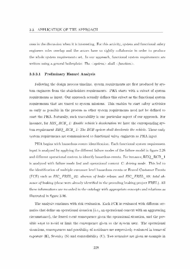
3.3. APPLICATION OF THE APPROACH
ones in the discussion when it is interesting. For this activity, system and functional safety
engineers roles overlap and the actors have to tightly collaborate in order to produce
the whole system requirements set. In our approach, functional system requirements are
written using a general boilerplate: The <system> shall <function>.
3.3.3.1 Preliminary Hazard Analysis
Following the design process timeline, system requirements are �rst produced by sys-
tem engineers from the stakeholders requirements. PHA starts with a subset of system
requirements as input. Our approach actually de�nes this subset as the functional system
requirements that are traced to system missions. This enables to start safety activities
as early as possible in the process as other system requirements need not be de�ned to
start the PHA. Naturally, such traceability is one particular aspect of our approach. For
instance, for MIS_RCB_1: Enable vehicle's deceleration we have the corresponding sys-
tem requirement REQ_RCB_1: The RCB system shall decelerate the vehicle. These early
system requirements are communicated to functional safety engineers as PHA input
PHA begins with hazardous events identi�cation. Each functional system requirement
input is analyzed by applying the di�erent failure modes of the failure model in �gure 2.28
and di�erent operational context to identify hazardous events. For instance, REQ_RCB_1
is analyzed with failure mode lost and operational context C: driving mode. This led to
the identi�cation of multiple customer level hazardous events or Feared Customer Events
(FCE) such as EIC_FREL_02: absence of brake release and EIC_FREL_09: total ab-
sence of braking (these were already identi�ed in the preceding braking project FREL). All
these informations are recorded in the ontology with appropriate concepts and relations as
illustrated in �gure 3.16.
The analysis continues with risk evaluation. Each FCE is evaluated with di�erent sce-
narios that de�ne an operational situation (i.e., an operational context with an aggravating
circumstance), the feared event consequence given the operational situation, and the pos-
sible ways to avoid or limit the consequence given to the system user. The operational
situations, consequences and possibility of avoidance are respectively evaluated in terms of
exposure (E), Severity (S) and controllability (C). Two scenarios are given as example in
228
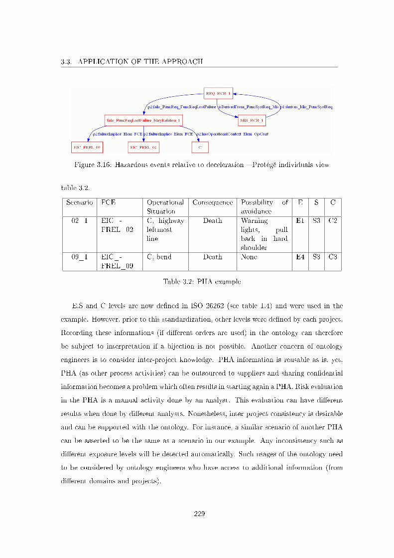
3.3. APPLICATION OF THE APPROACH
Figure 3.16: Hazardous events relative to deceleration � Protégé individuals view
table 3.2.
Scenario FCE OperationalSituation
Consequence Possibility ofavoidance
E S C
02_1 EIC_-FREL_02
C, highwayleftmostline
Death Warninglights, pullback in hardshoulder
E1 S3 C2
09_1 EIC_-FREL_09
C, bend Death None E4 S3 C3
Table 3.2: PHA example
E,S and C levels are now de�ned in ISO 26262 (see table 1.4) and were used in the
example. However, prior to this standardization, other levels were de�ned by each project.
Recording these informations (if di�erent orders are used) in the ontology can therefore
be subject to interpretation if a bijection is not possible. Another concern of ontology
engineers is to consider inter-project knowledge. PHA information is reusable as is, yet,
PHA (as other process activities) can be outsourced to suppliers and sharing con�dential
information becomes a problem which often results in starting again a PHA. Risk evaluation
in the PHA is a manual activity done by an analyst. This evaluation can have di�erent
results when done by di�erent analysts. Nonetheless, inter project consistency is desirable
and can be supported with the ontology. For instance, a similar scenario of another PHA
can be asserted to be the same as a scenario in our example. Any inconsistency such as
di�erent exposure levels will be detected automatically. Such usages of the ontology need
to be considered by ontology engineers who have access to additional information (from
di�erent domains and projects).
229
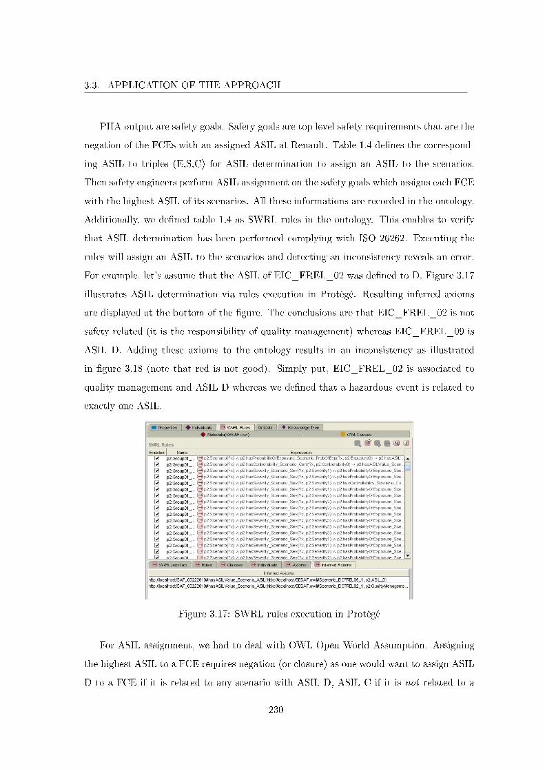
3.3. APPLICATION OF THE APPROACH
PHA output are safety goals. Safety goals are top level safety requirements that are the
negation of the FCEs with an assigned ASIL at Renault. Table 1.4 de�nes the correspond-
ing ASIL to triples (E,S,C) for ASIL determination to assign an ASIL to the scenarios.
Then safety engineers perform ASIL assignment on the safety goals which assigns each FCE
with the highest ASIL of its scenarios. All these informations are recorded in the ontology.
Additionally, we de�ned table 1.4 as SWRL rules in the ontology. This enables to verify
that ASIL determination has been performed complying with ISO 26262. Executing the
rules will assign an ASIL to the scenarios and detecting an inconsistency reveals an error.
For example, let's assume that the ASIL of EIC_FREL_02 was de�ned to D. Figure 3.17
illustrates ASIL determination via rules execution in Protégé. Resulting inferred axioms
are displayed at the bottom of the �gure. The conclusions are that EIC_FREL_02 is not
safety related (it is the responsibility of quality management) whereas EIC_FREL_09 is
ASIL D. Adding these axioms to the ontology results in an inconsistency as illustrated
in �gure 3.18 (note that red is not good). Simply put, EIC_FREL_02 is associated to
quality management and ASIL D whereas we de�ned that a hazardous event is related to
exactly one ASIL.
Figure 3.17: SWRL rules execution in Protégé
For ASIL assignment, we had to deal with OWL Open World Assumption. Assigning
the highest ASIL to a FCE requires negation (or closure) as one would want to assign ASIL
D to a FCE if it is related to any scenario with ASIL D, ASIL C if it is not related to a
230
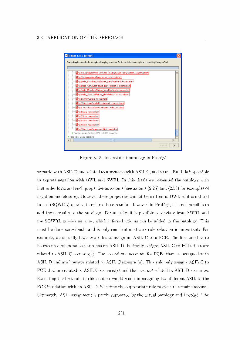
3.3. APPLICATION OF THE APPROACH
Figure 3.18: Inconsistent ontology in Protégé
scenario with ASIL D and related to a scenario with ASIL C, and so on. But it is impossible
to express negation with OWL and SWRL. In this thesis we presented the ontology with
�rst order logic and such properties as axioms (see axioms (2.25) and (2.53) for examples of
negation and closure). However these properties cannot be written in OWL so it is natural
to use (SQWRL) queries to return these results. However, in Protégé, it is not possible to
add these results to the ontology. Fortunately, it is possible to deviate from SWRL and
use SQWRL queries as rules, which inferred axioms can be added to the ontology. This
must be done consciously and is only semi automatic as rule selection is important. For
example, we actually have two rules to assign an ASIL C to a FCE. The �rst one has to
be executed when no scenario has an ASIL D. It simply assigns ASIL C to FCEs that are
related to ASIL C scenario(s). The second one accounts for FCEs that are assigned with
ASIL D and are however related to ASIL C scenario(s). This rule only assigns ASIL C to
FCE that are related to ASIL C scenario(s) and that are not related to ASIL D scenarios.
Executing the �rst rule in this context would result in assigning two di�erent ASIL to the
FCE in relation with an ASIL D. Selecting the appropriate rule to execute remains manual.
Ultimately, ASIL assignment is partly supported by the actual ontology and Protégé. The
231
3.3. APPLICATION OF THE APPROACH
ontology enables to detect errors done during this activity. Complete support of these
axioms as they are de�ned in this thesis is possible with a dedicated application in parallel
to the OWL ontology which exceeded the scope of this work.
Finally, safety goals are stakeholders requirements from the system engineers view-
point and their consideration is similar with relative system requirements. From the safety
point of view, a safety goal is the negation of a FCE with an ASIL. For example for
EIC_FREL_09 we have the following safety goal: No total absence of braking, ASIL D.
In the ontology, the two viewpoints are merged such that the more precise conceptualiza-
tion from systems engineering predominates. Safety goals are therefore expressed using
the stakeholder requirement boilerplate: The safety engineer shall be able to verify that
there is no total absence of braking, ASIL D. This stakeholder requirement is naturally put
in relation with the functional system requirement that accounts for vehicle deceleration
(REQ_RCB_1: The RCB system shall decelerate the vehicle). Finally, the PHA de�nes
safety goals from the functional system requirements in relation with a mission. As ex-
plained in section 2.3.2.2 ontology engineers start ASIL propagation to assign the highest
ASIL of the FCEs of a functional system requirements to each requirement. This enables
to also assign ASIL QM (for quality management) as safety goals are de�ned for ASIL
more stringent than QM.
3.3.3.2 Functional System Requirements De�nition
As it can be seen in �gure 2.52, system engineers are responsible for this activity.
Nonetheless, safety engineers are also responsible to produce functional system require-
ments that are relative to safety. Safety engineers further develop the safety goals (that
are stakeholders requirements from systems engineering viewpoint) into the so called func-
tional safety requirements as unacceptable risk has been detected. These two activities
are performed in parallel but functional system requirements and functional safety require-
ments concepts overlap therefore we made them precise in the ontology by stating that a
functional safety requirement is a type of functional system requirement (a subclass). Un-
der this interpretation, functional safety requirements are expressed with the boilerplate
for functional system requirements that involves a function. In fact, the term functional
232
3.3. APPLICATION OF THE APPROACH
safety requirements accounts for functional and non functional requirements as illustrated
in �gure 2.52 where the functional safety requirements are sent over to system engineers as
input for functional and non functional system requirements de�nition. We lose this de�ni-
tion in the ontology so that ontology engineers cannot simply record the functional safety
requirements de�ned by safety engineers as instances of functional system requirements.
Only functional ones (i.e., related directly or indirectly to a function with appropriate
properties) are recorded as instances of the class functional safety requirement. Others are
recorded in non functional classes. Similarly, functional system requirements developed by
system engineers can actually be safety related (if they are assigned with an ASIL di�er-
ent than QM) so these have to be asserted as functional safety requirements by ontology
engineers.
In our conceptualization, functional system requirements derived from system missions
correspond to the top level elements of the functional requirements hierarchy. We con-
cluded the previous section with the ASIL assignment to these elements. In this activity,
system engineers produce more precise functional system requirements as usual. The in-
teresting part concerns functional safety and our application of ASIL decomposition on
functional requirements presented in section 2.2.2.2. Functional safety engineers produce
more and more precise functional system requirements. Additionally, they can emit inde-
pendence requirements on the system functionalities (in the general sense of the term as
system functions do not yet exist) which will be materialized in the system architecture
(functional and physical). This enables to consider safety in the domain of the problem
(speci�cation) to guide the production of conceptually safe architectures (design). This
improves the current outdated view on system design process were system engineers �rst
de�ne the system architecture, which is then analyzed by safety engineers who emit rec-
ommendations for securing the architectures (if tolerable risk is not achieved), which are
taken into account by system engineers with a de�nition of a secured architecture of the
system. In the ontology, the recommendations correspond to system requirements (and
independence requirements between functional requirements) and the system architecture
corresponds to the �nal secured architecture.
These concepts correspond to our interpretation of ISO 26262 for Renault. ASIL decom-
233
3.3. APPLICATION OF THE APPROACH
position is relatively new and we had no real data to work with so the following examples
concerning ASIL decomposition and ASIL propagation were de�ned to present di�erent
uses of the ontology. The functional system requirements are hierarchically structured
with sub-requirements being more accurate than super-requirements. For instance, we
have super-requirement REQ_RCB_107 that has REQ_RCB_179 and REQ_RCB_180
as sub-requirements:
REQ_RCB_107: The RCB system shall know the estimated position of the service
brake command HMI from the pressure in the hydraulic network or the mechanical position
of the service brake HMI.
REQ_RCB_179: The RCB system shall know the pressure in the hydraulic network.
REQ_RCB_180: The RCB system shall know the mechanical position of the service
brake HMI.
These requirements are actually sub-requirements of precedent top level functional
system requirement REQ_RCB_1 that is ASIL D. Intuitively, the failure of REQ_RCB_-
107 leads contextually to catastrophic consequences and should be assigned with ASIL D
(assuming ASIL decomposition was not previously done for its super-requirements). The
two sub-requirements are actually functionally redundant as it is still possible to estimate
the position of the service brake with only one piece of information. Functional safety
engineers can perform ASIL decomposition on these three requirements with the ASIL D
being decomposed into two independent ASIL B (requirements). Given the ASIL of top
level functional system requirements and information when ASIL decomposition applies,
ontology engineers can execute SWRL rules (fundamentally SQWRL queries) to perform
ASIL propagation in the functional system requirements hierarchical structure. The ASIL
D of REQ_RCB_1 is propagated to all its sub-requirements and when it reaches REQ_-
RCB_107, it is decomposed into two ASIL B for REQ_RCB_179 and REQ_RCB_180
(if they are not related with another super-requirement with a higher ASIL in which case
it is the highest that is assigned). Figure 3.19 is a partial view of these informations.
ASIL propagation has been de�ned to gain more insights from future use of ASIL
decomposition by safety engineers. This is completely new as assigning ASIL to functional
234
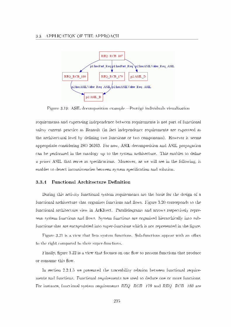
3.3. APPLICATION OF THE APPROACH
Figure 3.19: ASIL decomposition example � Protégé individuals visualization
requirements and expressing independence between requirements is not part of functional
safety current practice at Renault (in fact independence requirements are expressed at
the architectural level by de�ning two functions or two components). However it seems
appropriate considering ISO 26262. For now, ASIL decomposition and ASIL propagation
can be performed in the ontology up to the system architecture. This enables to de�ne
a priori ASIL that serve as speci�cations. Moreover, as we will see in the following, it
enables to detect inconsistencies between system speci�cation and solution.
3.3.4 Functional Architecture De�nition
During this activity functional system requirements are the basis for the design of a
functional architecture that organizes functions and �ows. Figure 3.20 corresponds to the
functional architecture view in ArKItect. Parallelograms and arrows respectively repre-
sent system functions and �ows. System functions are organized hierarchically into sub-
functions that are encapsulated into super-functions which is not represented in the �gure.
Figure 3.21 is a view that lists system functions. Sub-functions appear with an o�set
to the right compared to their super-functions.
Finally, �gure 3.22 is a view that focuses on one �ow to present functions that produce
or consume this �ow.
In section 2.2.1.5 we presented the traceability relation between functional require-
ments and functions. Functional requirements are used to deduce one or more functions.
For instance, functional system requirements REQ_RCB_179 and REQ_RCB_180 are
235

3.3. APPLICATION OF THE APPROACH
Figure 3.20: RCB functional architecture view in ArKItect
236
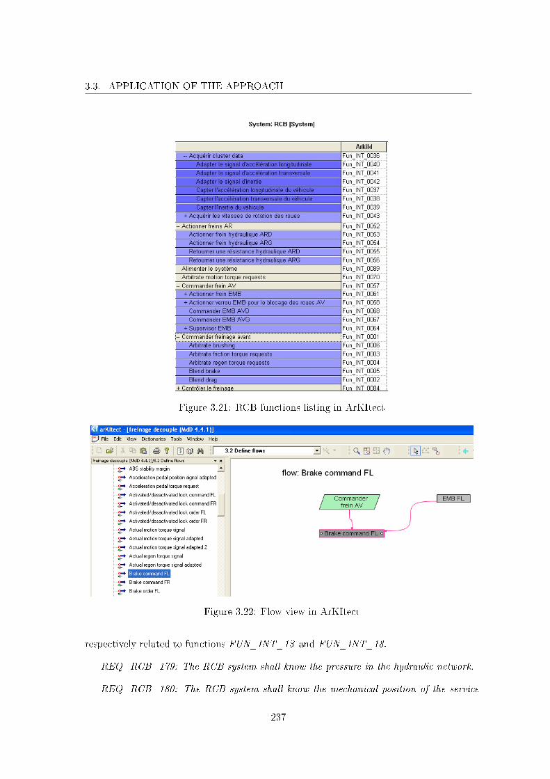
3.3. APPLICATION OF THE APPROACH
Figure 3.21: RCB functions listing in ArKItect
Figure 3.22: Flow view in ArKItect
respectively related to functions FUN_INT_13 and FUN_INT_18.
REQ_RCB_179: The RCB system shall know the pressure in the hydraulic network.
REQ_RCB_180: The RCB system shall know the mechanical position of the service
237
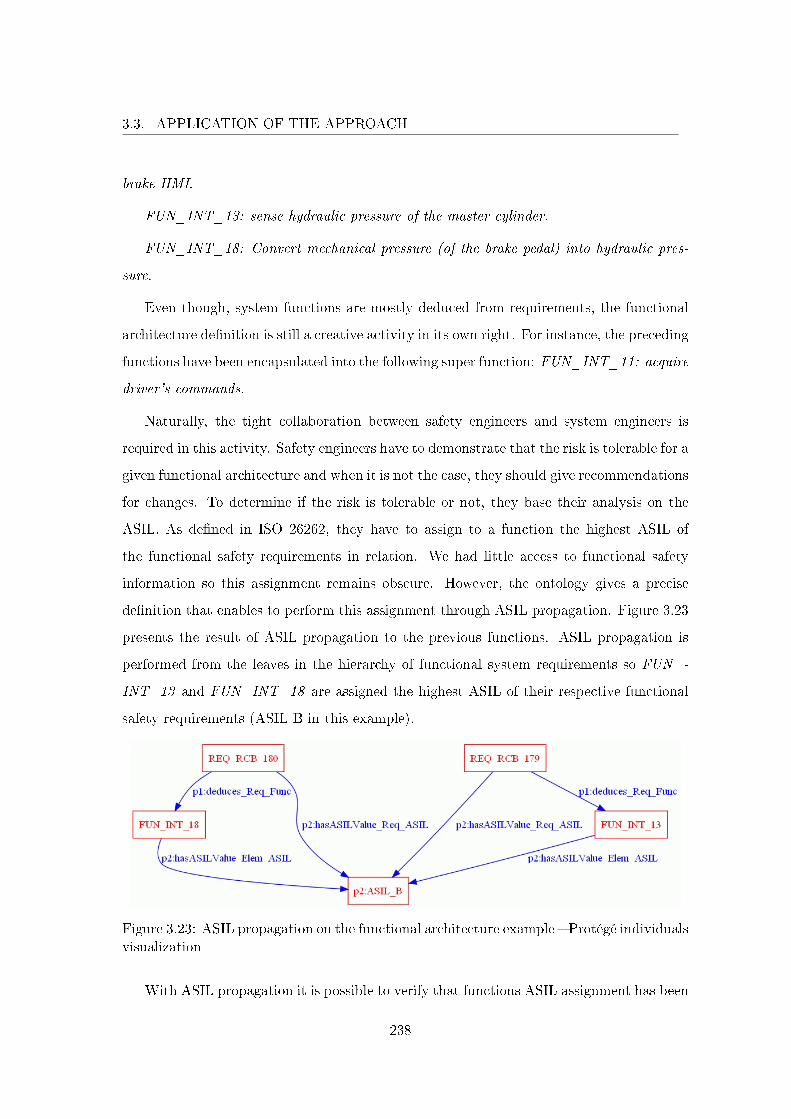
3.3. APPLICATION OF THE APPROACH
brake HMI.
FUN_INT_13: sense hydraulic pressure of the master cylinder.
FUN_INT_18: Convert mechanical pressure (of the brake pedal) into hydraulic pres-
sure.
Even though, system functions are mostly deduced from requirements, the functional
architecture de�nition is still a creative activity in its own right. For instance, the preceding
functions have been encapsulated into the following super function: FUN_INT_11: acquire
driver's commands.
Naturally, the tight collaboration between safety engineers and system engineers is
required in this activity. Safety engineers have to demonstrate that the risk is tolerable for a
given functional architecture and when it is not the case, they should give recommendations
for changes. To determine if the risk is tolerable or not, they base their analysis on the
ASIL. As de�ned in ISO 26262, they have to assign to a function the highest ASIL of
the functional safety requirements in relation. We had little access to functional safety
information so this assignment remains obscure. However, the ontology gives a precise
de�nition that enables to perform this assignment through ASIL propagation. Figure 3.23
presents the result of ASIL propagation to the previous functions. ASIL propagation is
performed from the leaves in the hierarchy of functional system requirements so FUN_-
INT_13 and FUN_INT_18 are assigned the highest ASIL of their respective functional
safety requirements (ASIL B in this example).
Figure 3.23: ASIL propagation on the functional architecture example � Protégé individualsvisualization
With ASIL propagation it is possible to verify that functions ASIL assignment has been
238
3.3. APPLICATION OF THE APPROACH
done consistently compared to the ontology. Ontology engineers can record ASIL assigned
to functions, execute ASIL propagation based on the functional system requirements and
functional architecture structure, and detect any inconsistency revealing important matters
to consider. Safety engineers can however perform a posteriori ASIL tailoring with critical-
ity analysis. This safety study enables to reduce the ASIL of an architectural element (i.e.,
a function or a component) that can invalidate ASIL propagation. For example, as a result
of criticality analysis, FUN_INT_13 can be assigned with ASIL A. This analysis is done
later in the process compared to ASIL decomposition and is therefore more relevant (as the
system is better understood). It results that the correct ASIL to be assigned to FUN_-
INT_13 is really A and not B. Nevertheless, performing ASIL propagation will result in
a contradiction that will lead to question why it is not ASIL B that is assigned ensuring
that necessary information (criticality analysis data) that resulted in ASIL tailoring exist.
Finally, the ontology can also be used to verify inter model consistency and gain more
insights from this level of detail. As it can be seen in �gures 3.6 and 3.20 di�erent de-
scriptions and models can be developed concerning similar information. The ontology at
the instance level is actually the global system model. Let us assume that �gure 3.6 is
another functional architecture and that we de�ned adequate mappings to record the two
descriptions into the ontology (for example circles in �gure 3.6 represent sensors that can
be interpreted as sensing functions, e.g., sense MC pressure and pedal stroke for the brake
pedal circle). One di�culty for ontology engineers is that they have to identify equivalent
individuals and assert that they are the same in the ontology. This is done only once and
it formalizes the interconnection between di�erent documents and models. It should also
be relatively easy as the common point of all the process actors is that they develop the
same system. If it is not the case, ontology engineers might ask whether or not it is really
the same system that is being developed. In this example, sense MC pressure and pedal
stroke is asserted to be the same as FUN_INT_11.
FUN_INT_11: acquire driver's commands.
Checking the ontology consistency ontology will guaranty that all models are consistent.
Given our hypothesis, consistency checking will be negative in this example. At the bottom
right hand side of �gure 3.6, we �nd two �ows that are produced by sense MC pressure and
239
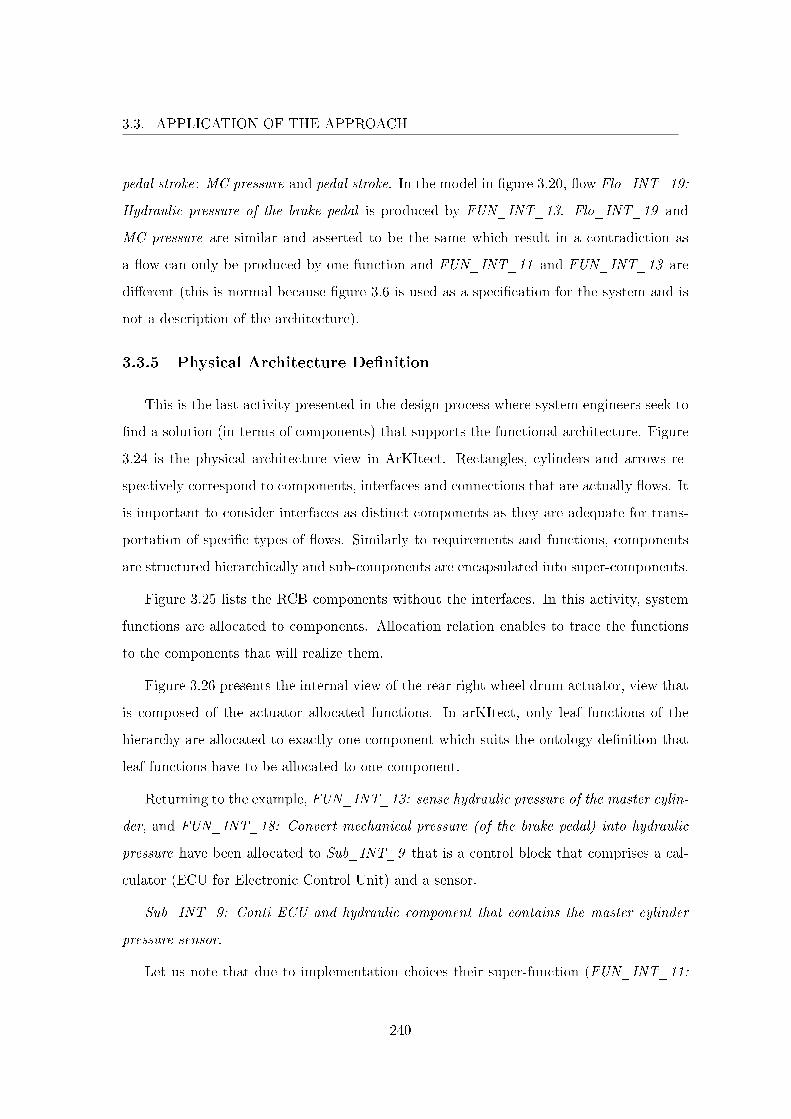
3.3. APPLICATION OF THE APPROACH
pedal stroke: MC pressure and pedal stroke. In the model in �gure 3.20, �ow Flo_INT_19:
Hydraulic pressure of the brake pedal is produced by FUN_INT_13. Flo_INT_19 and
MC pressure are similar and asserted to be the same which result in a contradiction as
a �ow can only be produced by one function and FUN_INT_11 and FUN_INT_13 are
di�erent (this is normal because �gure 3.6 is used as a speci�cation for the system and is
not a description of the architecture).
3.3.5 Physical Architecture De�nition
This is the last activity presented in the design process where system engineers seek to
�nd a solution (in terms of components) that supports the functional architecture. Figure
3.24 is the physical architecture view in ArKItect. Rectangles, cylinders and arrows re-
spectively correspond to components, interfaces and connections that are actually �ows. It
is important to consider interfaces as distinct components as they are adequate for trans-
portation of speci�c types of �ows. Similarly to requirements and functions, components
are structured hierarchically and sub-components are encapsulated into super-components.
Figure 3.25 lists the RCB components without the interfaces. In this activity, system
functions are allocated to components. Allocation relation enables to trace the functions
to the components that will realize them.
Figure 3.26 presents the internal view of the rear right wheel drum actuator, view that
is composed of the actuator allocated functions. In arKItect, only leaf functions of the
hierarchy are allocated to exactly one component which suits the ontology de�nition that
leaf functions have to be allocated to one component.
Returning to the example, FUN_INT_13: sense hydraulic pressure of the master cylin-
der, and FUN_INT_18: Convert mechanical pressure (of the brake pedal) into hydraulic
pressure have been allocated to Sub_INT_9 that is a control block that comprises a cal-
culator (ECU for Electronic Control Unit) and a sensor.
Sub_INT_9: Conti ECU and hydraulic component that contains the master cylinder
pressure sensor.
Let us note that due to implementation choices their super-function (FUN_INT_11:
240
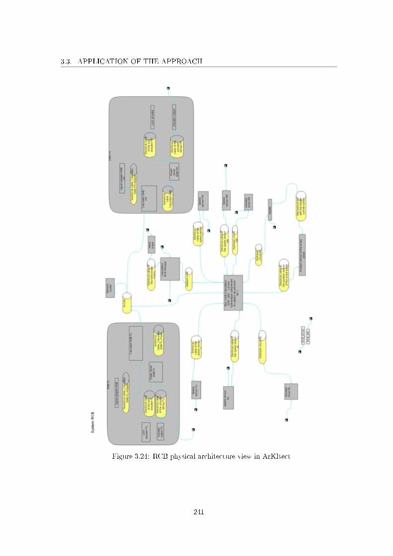
3.3. APPLICATION OF THE APPROACH
Figure 3.24: RCB physical architecture view in ArKItect
241
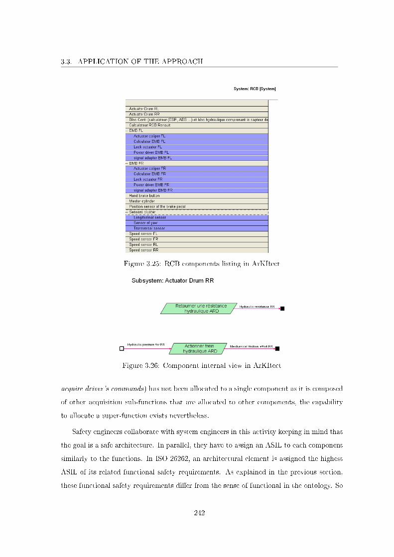
3.3. APPLICATION OF THE APPROACH
Figure 3.25: RCB components listing in ArKItect
Figure 3.26: Component internal view in ArKItect
acquire driver's commands) has not been allocated to a single component as it is composed
of other acquisition sub-functions that are allocated to other components, the capability
to allocate a super-function exists nevertheless.
Safety engineers collaborate with system engineers in this activity keeping in mind that
the goal is a safe architecture. In parallel, they have to assign an ASIL to each component
similarly to the functions. In ISO 26262, an architectural element is assigned the highest
ASIL of its related functional safety requirements. As explained in the previous section,
these functional safety requirements di�er from the sense of functional in the ontology. So
242
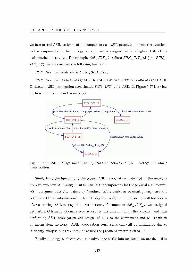
3.3. APPLICATION OF THE APPROACH
we interpreted ASIL assignment on components as ASIL propagation from the functions
to the components. In the ontology, a component is assigned with the highest ASIL of the
leaf functions it realizes. For example, Sub_INT_9 realizes FUN_INT_13 (and FUN_-
INT_18 ) but also realizes the following function:
FUN_INT_86: control base brake (BFD, ABS).
FUN_INT_86 has been assigned with ASIL D so Sub_INT_9 is also assigned ASIL
D through ASIL propagation even though FUN_INT_13 is ASIL B. Figure 3.27 is a view
of these informations in the ontology.
Figure 3.27: ASIL propagation on the physical architecture example � Protégé individualsvisualization
Similarly to the functional architecture, ASIL propagation is de�ned in the ontology
and explains how ASIL assignment is done on the components for the physical architecture.
ASIL assignment activity is done by functional safety engineers so ontology engineers role
is to record these informations in the ontology and verify that consistency still holds even
after executing ASIL propagation. For instance, if component Sub_INT_9 was assigned
with ASIL C from functional safety, recording this information in the ontology and then
performing ASIL propagation will assign ASIL D to the component and will result in
an inconsistent ontology. ASIL propagation conclusions can still be invalidated due to
criticality analysis but this does not reduce the produced information value.
Finally, ontology engineers can take advantage of the information structure de�ned in
243
3.3. APPLICATION OF THE APPROACH
the ontology and use it as a knowledge base by de�ning and executing di�erent queries
to bring important information to the surface (traceability coverage analyses, multi-model
informations such as the complete set of functions allocated to a controller, etc.).
3.3.6 Conclusion
In this section the design approach presented in the previous chapter has been applied
on the RCB project. The ontology centric design process has been developed so as not
to completely change the current design process at Renault but to be based on the latter
by explaining previously imprecise activities and by inserting the new role of ontology en-
gineer. The ontology engineer veri�es consistency issues that result mostly from parallel
development branches. In particular, systems engineering and functional safety domains
are two development branches that manipulate similar concepts that needed to be inte-
grated for better synergy. The results presented in this application comes from the shared
conceptualization and are threefold:
First: the integration of systems engineering and functional safety domains gives a
precise and unique interpretation to previously similar notions with incompatible de�nitions
(e.g., functional system requirements and functional safety requirements) and therefore
the information recorded in the ontology is not subject to implicit interpretations, gives
an ontology compliant (conceptually) description of the system and is potentially more
reusable.
Second: all the important system level (design) concepts of ISO 26262 have been de�ned
and integrated with Renault own concepts. This integration provides the very precise
foundations for the ontology design process for safety critical systems that is an answer for
Renault to a development process that complies with ISO 26262.
Finally: the ontology based design process answers the consistency challenge caused by
information loss at the processes interfaces (especially when the interface is a third party)
as consistency can now be veri�ed by ontology engineers.
244
3.4. CHAPTER CONCLUSION
3.4 Chapter Conclusion
In this chapter we presented the history of electric braking at Renault and the appli-
cation of ontology centric design process for safety critical systems on the RCB project.
The most important conclusion learned from precedent electric braking projects was that
safety critical systems development requires the automobile constructor to position itself as
a system developer rather than an integrator of commercial solutions (e.g., COTS) that are
not completely mastered and that the company is liable for. Systems engineering is cur-
rently undergoing de�nition and deployment at Renault to address the system dimension
shortcoming. In addition, international standard ISO 26262 is also a big item of concern
and this work is part of multiple initiatives to adapt the development process in order to
be compliant with this standard. Our proposition, the ontology centric design process,
is structured around an ontology that enables to record very precisely all informations
relative to one system design. The design process is requirement driven so the informa-
tion records the top-down nature of the process. Even though it was actually possible
to record most of the study case information, this has been done with relative di�culty
as the project information has been produced without the formalized conceptualization.
Nonetheless, the central ontology (at the conceptual level) was su�ciently general and
precise so that most of the produced information from systems engineering and functional
safety could be recorded precisely in the ontology. This study has been developed only to
demonstrate the process capabilities and is also an example of project capitalization that
is more appropriate for reuse than documents and models (that are hardly integrated). Let
us note that to really be able to evaluate our process requires that it is applied to more
projects. The construction of the ontology at the conceptual level has been fundamental
to this work and has involved several changes that were problematic for the instantiation
of project information. Moreover, not only some information was missing and therefore
could not be added to the ontology, we have also identi�ed and de�ned concepts that were
not part of the project conceptualization, such as ASIL assignment from the main system
functionalities. At the instance level, we recorded provided information that amounts to
66 requirements, 79 functions, 83 �ows and 71 components. Traceability information was
missing and has been only partially de�ned to verify the implemented concepts. As we
245
3.4. CHAPTER CONCLUSION
have de�ned a di�erent conceptualization for ASIL assignment that uses traceability in-
formation and ASIL decomposition (information not provided) we performed risk analysis
on two functional requirements and only veri�ed that ASIL propagation was working on
small examples. Ultimately, missing information mainly concerns relations between dif-
ferent concepts. Queries can be de�ned to reveal when information is missing. It would
amount up to hundreds which reveals that tools are essential for industrial size projects
that are generally even more complex.
The process and the ontology have proved satisfactory even though an ontology being
incomplete by nature impacts appreciation of general and precise characteristics. The on-
tology de�nes the general concepts of design (e.g., requirement, function, �ow, component,
ASIL) that enable to record imprecisely the information of any automotive safety critical
system. Naturally, we want this information to be precise which is done with additional
concepts, sub-concepts and constraints. Additional axioms can also be de�ned to complete
the ontology for more preciseness. For instance, other requirements attributes such as pri-
ority (requirements are considered according to their priority) and �exibility (requirements
are more or less imperative) could be de�ned. To conclude, the work presented in this
thesis is an improved development process at Renault answering the rigor required when
developing safety critical systems, it de�nes all the principles that enables to improve de-
sign models quality and consistency through an ontology, and it has enriched the re�exion
with further investigations presented in the next chapter that concludes the thesis.
246
Conclusions and Future Work
Conclusions
The goal of this thesis is to bring a contribution to adapt and improve the development
process for safety critical mechatronics systems at Renault. We observed that the process
could bene�t from more formalization as it was de�ned imprecisely and changes were
required because of international standard ISO 26262 on functional safety. In order to
achieve this goal, we have investigated the following research questions:
Q1 How can domain knowledge (i.e., automobile domain knowledge) be formalized ?
Q2 How can expert knowledge about the development process be formalized ?
Q3 How can conformance to standard ISO 26262 be veri�ed ?
Chapter 1 presents systems engineering and functional safety which are the two domains
formalized and integrated in this work. It then goes through ontologies in general to focus
on formal ontologies with OWL, SWRL and SQWRL languages. Formal ontologies were
proposed to formalize a conceptualization of a domain with a formal semantics. The use
of OWL and SWRL enables to formally de�ne a domain therefore answering question
Q1. Moreover, we chose to formalize process activities inputs and outputs so that expert
knowledge coincides with domain knowledge and therefore the formalization also answers
question Q2. Finally, formal languages consistency checking is an automatic analysis that
enables to verify the consistency of an ontology and answers question Q3 as we formalized
part of ISO 26262.
Chapter 2 presents the contributions. We chose to focus only on the design part of the
system development process. We �rst identi�ed that the documents and models produced
247
CONCLUSIONS AND FUTURE WORK
during the design process su�er from many semantic inconsistencies. In general, design is
a collaborative process involving di�erent actors that can have di�erent implicit domain
conceptualizations.
Our �rst contribution is the proposal to use ontologies to formalize an explicit concep-
tualization of a domain at Renault. This idea is presently accepted completely.
The second contribution consists in two ontologies on systems engineering that is rela-
tively new and functional safety that is subject to change due to the publication of standard
ISO 26262.
The third contribution is the integration of these two ontologies into one ontology
for safety critical mechatronics systems design. We identi�ed that these two domains
presented some incompatibilities, in particular on the requirement notion, and solved these
incompatibilities. The integration of these two domains enables to limit loss of knowledge
at the process interfaces which allows to work with more complete information that resulted
in a semi-automatic analysis for ASIL assignment called ASIL propagation because it is
based on the traceability de�ned in the ontology.
Our fourth contribution that achieves the goal of this thesis is an improved design
process that relies entirely on ontologies: the ontology centric design process.
The �fth contribution is the de�nition of the new role: ontology engineer.
We �rst presented the general principles of the approach. The ontology at the con-
ceptual level corresponds to the system data-model. At the instance level, the ontology
corresponds to the system consistency reference model. It is the global system model.
Working at the conceptual level enables to de�ne mappings between documents, models
and the ontology. This enables to enrich the ontology with the information contained in
the documents and models, to propagate the changes from one source to their di�erent
recipients and to check the consistency of the whole process (i.e., the consistency of all
documents and models). Then the approach is presented in details. The design process
at Renault is in a transitional phase oriented towards full model-based systems engineer-
ing. For now, each project decides how process inputs and outputs are produced using
documents or models. In anticipation of a future Renault speci�c seamless process (with
248
CONCLUSIONS AND FUTURE WORK
adequate tools), ontology centric design process introduces the new role of ontology engi-
neer to support this transition. Ontology engineers mission will be to guarantee the design
process consistency, ensuring that Renault needs are taken into account in accordance with
systems engineering in general and ISO 26262 in particular.
Finally, in chapter 3, we applied the process de�ned in this work to the Regenerative
Combi-Brake study case. The design process is improved in three ways.
First, it integrates formal ontologies which enables to ensure that consistency (also at
the semantic level) is attained in a project. The ontology at the instance level is the global
system model.
Second, it is better adapted for safety critical systems development as safety concepts
have been integrated with systems engineering in a precise unambiguous way whereas this
integration was previously implicit.
Third, it also complies with ISO 26262 as concepts of the standards are de�ned in the
ontology and used by the process.
We conclude on other prior results that are part of this thesis. The work described in
this thesis has been extensively presented at Renault. Two presentations have been given
to DELTA ("Direction de l'Électronique et des Technologies Avancées") director. The
work has also been presented during three internal meetings between di�erent departments
and several times for the team. Two six months internships were supervised on model
transformation and formal veri�cation. Three internal reports were produced. This work
has also been made available to the public with presentations in two research laboratories,
meetings between Renault and some partners and with three published papers two of
which are international. Finally, this work continues to be exploited as presented in the
next section.
Future Work
Sharing a conceptualization is invaluable. This actually addresses a peculiarity of the
human condition revealed by this quote from Peter Benary: "Misunderstanding is the most
frequent form of communication between people". The concepts presented in this thesis
249
CONCLUSIONS AND FUTURE WORK
bring many bene�ts in real world applications where systems are developed by humans.
Systems engineering discipline is de�ned by the INCOSE as "an interdisciplinary approach
and means to enable the realization of successful systems". Similarly, the extent of this work
exceeds disciplinary boundaries and there are still many aspects that can be improved and
need further research.
Related Work
The work presented in this thesis comes from Renault's decision to deploy systems
engineering and adds to the discussion with an additional ontology dimension. Related
works are performed based partially on our work. Lets us mention some of them.
Even though the ontology manipulates the requirement concept, it does not address
syntactic nor grammatical structure of natural language. Presently, a thesis is in progress
within the project RAMP (Requirement Analysis and Modeling Process). Its objective
is to improve the e�ciency and quality of requirements expressed in natural language
throughout the system life cycle. Expected outcomes are mainly but are not restricted
to better requirements authoring, better written requirements and better requirements
management and traceability. Identi�ed requirements parts would be associated with their
manifestation as concepts in the ontology.
Similarly, variability and optimization in the design process are the subject of respective
theses. The �rst one brings the idea of variability back to the design process as �rst
class element. Given the time constraints relative to development in the automotive, the
production of variability information (and therefore the evaluation of di�erent solutions
for the same system) remains very speci�c and most often very late in the design process.
The ontology is an input for conceptual elements upon which variability can be expressed
(e.g., requirements, functions, �ows, components, etc.). The second thesis is interested in
multi-objective optimization. The considered approach de�nes an optimization function
for a system, which depends on multiple parameters derived from needs and constraints on
the system. Following systems engineering these parameters should ultimately correspond
to attributes of concepts (e.g., components cost) or to �ows (e.g., the road slope parameter
impacts energy consumption during acceleration phases but the road is not a concept with
250
CONCLUSIONS AND FUTURE WORK
a slope attribute therefore it is recorded as a �ow) in the ontology.
Renault is also involved in many collaborative projects where the ontology and the
approach have a role to play. For instance, IMOFIS4 has studied possible modeling tools
speci�cally for safety considerations. Renault language has been implemented in the tools
enabling to produce models in Renault dialect. Modeling tools rely on modeling languages
(meta-models) and the ontology can actually also be considered as a Renault DSL (Domain
Speci�c Language). The ontology can either be viewed as a modeling tool meta-model
speci�cation (the ontology is therefore implemented as a meta-model) or mapped to a
tool meta-model giving more con�dence that Renault needs are taken into account. More
recently, Renault and the CEA5 have signed an R&D agreement on the green vehicle theme.
One research area concerns MBSSE (Model Based Systems and Software Engineering)
where system and software models are produced using Renault pro�les of SysML and
UML and will ultimately give some answers to systems engineering deployment at Renault.
The ontology centric process principles applies to this research area. More generally, our
work serves as the foundation of Renault reference framework for mechatronics system
development. In particular, the ontology is used as the base of the architecture framework
in this reference framework. This work can be seen as the means by which Renault will be
able to share its needs even more both internally and externally.
Finally, the work realized in this thesis is a theoretical work applied at Renault. It
results in a general approach that can be adapted to any environment of any company.
Personal Perspectives
Ontologies cannot be considered as static as there are many occasions that can lead
to changes such as changes in the conceptualized domain which leads to the fact that
the ontology does not re�ect the reality anymore. Ontology evolution is naturally a big
concern in the semantic web community as ontologies, central to semantic web systems,
are updated along the functionalities of ontology based systems.
In our context, we envision the addition of new concepts to the ontologies de�ned in
4IMOFIS (Ingénierie des MOdèles de FonctIons Sécuritaires), http://www.imofis.org5CEA (Commissariat à l'Énergie Atomique et aux Énergies Alternatives), http://www.cea.fr
251
CONCLUSIONS AND FUTURE WORK
this thesis. Four main areas for evolution are identi�ed.
First, the concept of requirement needs even more precisions. The ontology provides
basic modeling pattern for functional and non functional requirements. Speci�cally, func-
tional requirements are very precisely decomposed between one another and traced to
functions and components. Other concepts are required for the hard part that concerns
the non functional requirements. The non functional requirements considered in the on-
tology correspond only to requirements that have an interpretation relative to systems
engineering elements (i.e., functions, �ows and components). We have given some exam-
ples for weight, cost and execution time but this is relatively imprecise and needs further
investigation. The di�erent types of non functional requirements need to be identi�ed and
de�ned with their semantic relations and related concepts such as process requirements
that will be related to process concepts (activity, technique, etc.) for example.
Second, enabling to explicitly represent design choices and variability will bene�t sys-
tems engineering in general but also functional safety that takes a logic view of the ar-
chitectures when they study causes of feared customer events. For instance, the physical
consideration of a data acquisition requirement can involve di�erent types of sensors with
speci�c characteristics.
This leads to the third area for improvement: optimization analyses that enable to
compare two di�erent solutions to the same problem. For instance, system customer cost
could be used to di�erentiate between two solutions.
Fourth, as we only considered ISO 26262 parts that are relative to system level and
design, the entire V cycle remains to be addressed completely. In particular, the V cycle
ascending branch, i.e., the integration phase, that relates to veri�cation and validation
activities.
In this work, we integrated systems engineering and functional safety. The next logical
step is to integrate other domains or professional �elds involved in the interdisciplinary re-
alization of mechatronics systems. It is possible to emulate the approach presented in this
thesis by de�ning new ontologies and integrating them using imports and speci�c axioms.
In particular, software engineering is relatively close to systems engineering which is very
252
CONCLUSIONS AND FUTURE WORK
favorable for formalization and integration. Moreover ISO 26262 considers software as a
speci�c part which formalization could build upon this domain ontology. More generally,
the approach to de�ne domain ontologies and then integrate them is our answer to bet-
ter consider safety as a domain integrated to systems engineering and to make di�erent
domains work together by identifying incompatibilities and resolving them. The approach
contributes to the improvement of current practices for assignment, argumentation and
demonstration of system ASIL. We believe this approach can be adapted or implemented
to other normative contexts such as the other standards derived from IEC 61508 bringing
a solution to semantic consistency problems that exist in all industrial domains.
From the theoretical point of view, interesting perspectives would be to study alter-
native ontology languages. Nonmonotonic logics are characterized by a nonmonotonic
consequence relation, meaning that adding a formula to a theory can result in reducing its
set of consequences. This can be used to express integrity constraints for example. Even
though we have seen that it was possible to formalize the universe of discourse with OWL,
SWRL and SQWRL, a theory where the Open World Assumption and the Closed World
Assumption coexist and its applicability to the industry needs further research.
From the practical point of view, �rst, more results are needed which will require more
applications of the approach. On the one hand, the approach scalability when confronted to
the amount of information contained in industrial systems in production has to be assessed.
And on the other hand, the central ontology quality also needs to be evaluated to guide
ontology evolution.
Second, a quantitative evaluation of the communication between actors that uses our
approach and those that do not would characterizes ontologies as assets that are essential
or that contributes during development.
Given the diversity of tools that can be used during the design process and their rel-
ative volatility as it is being constructed, mappings are not yet tool supported. They are
however required by our approach: tooled mappings would guarantee ontology enrichment
and model consistent synchronization. New concepts will most certainly emerge from these
tools development which will lead to ontology evolution. Moreover, the ontology as the
global system model will most certainly appeal for more features, such as ASIL propaga-
253

CONCLUSIONS AND FUTURE WORK
tion de�ned in this thesis, therefore new tools that support additional features are also
considered for development.
254
Bibliography
[AUT] The AUTOSAR Consortium. URL www.autosar.org.
[EDO] Edona project. URL http://www.edona.fr.
[MEM] MeMVaTEx poroject. URL www.memvatex.org.
[ISO 1999] ISO/IEC Guide 51 Safety aspects � Guidelines for their Inclusion in Standards,
1999.
[IEC 2000] IEC 61508: Functional Safety of Electrical/Electronic/Programmable Electronic
Safety-Related Systems, 2000.
[ISO 2000] ISO 14971 Medical Devices � Application of Risk Management to Medical Devices,
2000.
[ISO 2002a] ISO/IEC 15288 Systems Engineering � System Life Cycle Processes, 2002a.
[ISO 2002b] ISO/IEC Guide 73 Risk management � Vocabulary � Guidelines for use in stan-
dards, 2002b.
[ISO 2007] ISO/IEC 24707 Information Technology � Common Logic (CL): A Framework for a
Family of Logic-Based Languages, 2007.
[Sys 2007] Systems Modeling Language (OMG SysML), 2007.
[UML 2007] Uni�ed Modeling Language Speci�cation, Version 2.1.1, 2007.
[ATT 2008] The ATESST Consortium: EAST-ADL 2.0 Speci�cation, 2008. URL www.atesst.
org.
255
BIBLIOGRAPHY
[INC 2009] Survey of Model-Based System engineering (MBSE) Methodologies. INCOSE, 2009.
[INC 2011] INCOSE Systems Engineering Handbook. Version 3.2.2. INCOSE, 2011.
[ISO 2011] International Standard ISO 26262: Road Vehicles � Functional Safety, 2011.
[AAAM 1998] AAAM, editor. The Abbreviated Injury Scale (1990) � Revision Update 1998. Des
Plaines/IL, 1998. Association for the Advancement of Automotive Medicine (AAAM).
[Albinet et al. 2007] A. Albinet, J.L. Boulanger, H. Dubois, M.A. Peraldi-Frati, Y. Sorel, and Q-
D. Van. Model-Based Methodology for Requirements Traceability in Embedded Systems.
3rd ECMDA workshop on traceability, 2007.
[Albinet et al. 2010] A. Albinet, L. Quéran, B. Sanchez, and Y. Tanguy. Requirement man-
agement from System modeling to AUTOSAR SW Components. Embedded Real Time
Software and Systems (ERTS22010), 2010.
[Anneke et al. 2003] K. Anneke, W. Jos, and B. Wim. MDA Explained: The Model Driven
Architectur: Practice and Promise. Addison Wesley, 2003.
[Avizienis et al. 2004] A. Avizienis, J.-C. Laprie, B. Randell, and C. Landwehr. Basic Concepts
and Taxonomy of Dependable and Secure Computing. IEEE Transactions on Dependable
and Secure Computing, 1(1):11�33, Jan.-March 2004.
[Berners-Lee et al. 2001] Tim Berners-Lee, James Hendler, and Ora Lassila. The Semantic Web.
Scienti�c American, 284(5):34�43, 2001.
[Bishop 2008] Robert H. Bishop. Mechatronic Systems, Sensors, and Actuators: Fundamentals
and Modeling. The Electrical Engineering Handbook Series, The Mechatronics Hand-
book, Second Edition Series, Volume 1. 2008.
[Booch et al. 2005] G. Booch, J. Rumbaugh, and I. Jacobson. The Uni�ed Modeling Language
User Guide. Addison-Wesley, second edition, 2005.
[Boulanger 2006] Jean-Louis Boulanger. Expression et validation des propriétés de sécurité
logique et physique pour les systèmes informatiques critiques. PhD thesis, Université
de Technologie de Compiègne, 2006.
256
BIBLIOGRAPHY
[Brinkkemper et al. 2008] Sjaak Brinkkemper, Inge van de Weerd, Motoshi Saeki, and Johan
Versendaal. Process Improvement in Requirements Management: A Method Engineering
Approach. In Requirements Engineering: Foundation for Software Quality, volume 5025
of Lecture Notes in Computer Science, pages 6�22. Springer Berlin / Heidelberg, 2008.
ISBN 978-3-540-69060-3.
[Brucker et al. 2006] Achim D. Brucker, Jürgen Doser, and Burkhart Wol�. Semantic Issues of
OCL: Past, Present and Future. ECEASST, pages �1�1, 2006.
[Burr et al. 2005] H. Burr, T. Deubel, M. Vielhaber, S. Haasis, and C. Weber. CAx/Engineering
Data Management Integration: Enabler for Methodical Bene�ts in the Design Process.
Journal of engineering design, 16(4):385�398, August 2005.
[Bussler 2003] Christoph Bussler. The Role of Semantic Web Technology in Enterprise Appli-
cation Integration. Data Engineering, 51(4):1�7, 2003.
[Chalé Góngora et al. 2010] H. G. Chalé Góngora, O. Tao�fenua, and T. Gaudré. A Process
and Data Model for Automotive Safety-Critical Systems Design. In 20th International
Symposium of the INCOSE, 2010.
[Chalé Góngora et al. 2011] H. G. Chalé Góngora, O. Tao�fenua, T. Gaudré, N. Lévy, J.L.
Boulanger, and A. Topa. Reducing the Gap Between Formal and Informal Worlds in
Automotive Safety-Critical Systems. 21st International Symposium of the INCOSE,
2011.
[Chalé Góngora et al. 2009] Hugo Guillermo Chalé Góngora, Ofaina Tao�fenua, and Thiery
Gaudré. Conception de Systèmes Critiques Automobiles - Étude de Mise en Oeuvre de
la Norme ISO26262. In Proceedings of 5ème Conférence Annuelle AFIS (Paris, France).
AFIS, 2009.
[Driouche et al. 2007] R. Driouche, Z. Boufaida, and F. Kordon. An Enterprise Application
Integration Architecture Supporting Ontology Based Approach for B2B Collaboration.
International Journal of Interoperability in Business Information Systems, 2(2):39�64,
September 2007.
257

BIBLIOGRAPHY
[Estefan 2008] Je� A Estefan. Survey of Model-Based Systems Engineering Methodologies
(MBSE) Rev B. Technical report, INCOSE-TD-2007-003-01, June 10 2008.
[Evans et al. 1998] Andy Evans, Robert France, Kevin Lano, and Bernhard Rumpe. The UML
as a Formal Modeling Notation. In Computer Standards & Interfaces, pages 336�348.
Springer, 1998. URL http://www.cs.york.ac.uk/puml/papers/evansuml.pdf.
[Friedenthal et al. 2008] Sanford Friedenthal, Alan Moore, and Rick Steiner. A practical guide
to SysML: Systems Model Language. OMG Press, 2008.
[Gao et al. 2007] David Wenzhong Gao, Chris Mi, and Ali Emadi. Modeling and Simulation
of Electric and Hybrid Vehicles. In IEEE, editor, Proceedings of the IEEE, volume 95,
pages 729�745, 2007.
[Gasevic et al. 2009] Dragan Gasevic, Dragan Djuric, and Vladan Devedzic. Model Driven En-
gineering and Ontology Development. Springer, 2 edition, 2009.
[Green et al. 2001] P. Green, M. Flynn, G. Vanderhagen, J. Ziiomek, E. Ullman, and K. Mayer.
Automotive Industry Trends in Electronics: Year 2000 Survey of Senior Executives. Tech-
nical Report UMTRI-2001-15, Ann Arbor, MI: University of Michigan Transportation
Research Institute., 2001.
[Gruber 1993] Thomas R. Gruber. A Translation Approach to Portable Ontology Speci�cations.
Knowledge Acquisition, 5(2):199�220, 1993.
[Gruber 2009] Tom Gruber. Ontology. In Encyclopedia of Database Systems, pages 1963�1965.
Springer US, 2009.
[Guarino 1998] N. Guarino. Formal Ontology and Information Systems. In Proceedings of the
1st Internationall Conference on Formal Ontologies in Information Systems (FOIS98)
(Trento, Italy), pages 3�15. IOS Press, 1998.
[Harmelen and Fensel 1995] Frank Van Harmelen and Dieter Fensel. Formal Methods in
Knowledge Engineering. The Knowledge Engineering Review, 10:345�360, 1995.
URL http://citeseerx.ist.psu.edu/viewdoc/download?doi=10.1.1.14.5746&rep=
rep1&type=pdf.
258
BIBLIOGRAPHY
[Herrmann 1999] Debra S. Herrmann. Software Safety and Reliability: Techniques, Approaches,
and Standards of Key Industrial Sectors. IEEE Computer Society, International Orga-
nization for Standardization (ISO) / International Electrotechnical Commission (IEC),
Washington, DC, USA, 1999.
[Horrocks et al. 2004] Ian Horrocks, Peter F. Patel-Schneider, Harold Boley, Said Tabet, Ben-
jamin Grosof, and Mike Dean. SWRL: A Semantic Web Rule Language Combining
OWL and RuleML. W3c member submission, World Wide Web Consortium, 2004.
URL http://www.w3.org/Submission/SWRL.
[Hull et al. 2004] Elizabeth Hull, Ken Jackson, and Jeremy Dick. Requirements Engineering.
SpringerVerlag, 2004.
[Huth and Ryan 2004] Michael Huth and Mark Ryan. Logic in Computer Science: Modelling
and Reasoning About Systems. Cambridge University Press, Second edition, 2004. ISBN
052154310X.
[Kergosien et al. 2010] Eric Kergosien, Mouna Kamel, Christian Sallaberry, Marie-Noëlle
Bessagnet, Nathalie Aussenac-Gilles, and Mauro Gaio. Construction et enrichissement
automatique d'ontologie à partir de ressources externes. CoRR, (abs/1002.0239), 2010.
[Levendovszky et al. 2002] T. Levendovszky, G. Karsai, M. Maroti, A. Lede-czi, and H. Charaf.
Model Reuse with Metamodel-Based Transformations. Lecture Notes In Computer Sci-
ence, 2319:166�178, 2002.
[Leveson 1995] Nancy G. Leveson. Safeware - System Safety and Computers. Addison-Wesley,
1995.
[Lykins et al. 2000] H. Lykins, S. Friedenthal, and A. Meilich. Adapting UML for an Object
Oriented Systems Engineering Method (OOSEM). In International Council on Systems
Engineering 10th Annual Symposium, 2000.
[Maiden et al. 2008] Neil Maiden, Cornelius Ncube, and James Lockerbie. Inventing Require-
ments: Experiences with an Airport Operations System. In Requirements Engineering:
Foundation for Software Quality, volume 5025 of Lecture Notes in Computer Science,
pages 58�72. Springer Berlin / Heidelberg, 2008.
259
BIBLIOGRAPHY
[McDermid 2001] John A McDermid. Software Safety: Where's the Evidence ? In Proceedings
of the Sixth Australian workshop on Safety critical systems and software (SCS'01), pages
1�6, Darlinghurst, Australia, 2001. Australian Computer Society, Inc.
[Micskei and Waeselynck 2010] Z. Micskei and H. Waeselynck. The many meanings of UML 2
Sequence Diagrams: a survey. Software and Systems Modeling, 2010.
[Motik et al. 2009] B. Motik, P.F. Patel-Schneider, and B. Parsia. OWL 2 Web Ontology Lan-
guage: Structural Speci�cation and Functional-Style Syntax. W3C Recommendation,
October 2009. URL http://www.w3.org/TR/owl2-syntax/.
[Motik et al. 2006] Boris Motik, Ian Horrocks, Riccardo Rosati, and Ulrike Sattler. Can OWL
and Logic Programming Live Together Happily Ever After ? In International Semantic
Web Conference, pages 501�514, 2006.
[O'Connor and Das 2009] Martin O'Connor and Amar Das. SQWRL: a Query Language for
OWL. OWL: Experiences and Directions (OWLED), 6th International Workshop, 2009.
[Papadopoulos et al. 2001] Y. Papadopoulos, J. Mcdermid, R. Sasse, and G. Heiner. Analysis
and synthesis of the behaviour of complex programmable electronic systems in conditions
of failure. Reliability Engineering & System Safety, 71(3):229�247, March 2001.
[Patel-Schneider et al. 2004] Peter F. Patel-Schneider, Patrick Hayes, and Ian Horrocks. OWL
Web Ontology Language Semantics and Abstract Syntax. W3C Recommendation, 10
February 2004. URL http://www.w3.org/TR/owl-semantics/.
[Roser and Bauer 2005] S. Roser and B. Bauer. Ontology-Based Model Transformation. MoD-
ELS 2005, Satellite Events, pages 355�356, 2005.
[Söderström et al. 2001] Eva Söderström, Birger Andersson, Paul Johannesson, Erik Perjons,
and Benkt Wangler. Towards a framework for comparing process modelling languages.
Lecture Notes In Computer Science, 2348:600�611, 2001. Proceedings of the 14th Inter-
national Conference on Advanced Information Systems Engineering.
[Sebastian et al. 2008] A. Sebastian, N. F. Noy, T. Tudorache, and M. A. Musen. A Generic On-
tology For Collaborative Ontology-Development Work�ows. In 16th International Con-
260

BIBLIOGRAPHY
ference on Knowledge Engineering and Knowledge Management (EKAW'08). Springer,
2008.
[Stevens et al. 1998] Richard Stevens, Peter Brook, Ken Jackson, and Stuart Arnold. Systems
Engineering: Coping with Complexity. Prentice Hall PTR, 1998.
[Struss and Price 2004] Peter Struss and Chris Price. Model-Based Systems in the Automotive
Industry. AI Mag, 24(4):17�34, Winter 2004.
[Stuckenschmidt and Harmelen 2005] H. Stuckenschmidt and F.V. Harmelen. Information
Sharing on the Semantic Web. Advanced information and knowledge processing.
Springer, 2005.
[Studer et al. 1998] Rudi Studer, V. Richard Benjamins, and Dieter Fensel. Knowledge Engi-
neering: Principles and Methods. Data and Knowledge Engineering, 25(1-2):161�197,
March 1998.
[Sure et al. 2002] York Sure, Ste�en Staab, and Rudi Studer. Methodology for Development and
Employment of Ontology Based Knowledge Management Applications. SIGMOD Rec.,
31(4):18�23, 2002. ISSN 0163-5808. doi: http://doi.acm.org/10.1145/637411.637414.
[Suwanmanee et al. 2005] S. Suwanmanee, D. Benslimane, and P. Thiran. OWL-based approach
for semantic interoperability. 19th International Conference on Advanced Information
Networking and Applications (AINA 2005), 1:145�150, 2005.
[Tudorache 2006] Tania Tudorache. Employing Ontologies for an Improved Development Pro-
cess in Collaborative Engineering. PhD thesis, Technical University of Berlin, Shcool of
Electrical Engineering and Computer Science, 2006.
[Ungermann 2009] Jörn Ungermann. On Clock Precision Of FlexRay Communication Clusters,
2009. URL http://flexray.com/publications/On_Clock_Precision_Of_FlexRay_
Communication_Clusters.pdf.
[Webers et al. 2008] Wolfram Webers, Christer Thörn, and Kurt Sandkuhl. Connecting feature
models and AUTOSAR: An approach supporting requirements engineering in automotive
261
industries. In Requirements Engineering: Foundation for Software Quality, volume 5025
of Lecture Notes in Computer Science, pages 95�108. Springer Berlin / Heidelberg, 2008.
[Wieringa 2004] R.J. Wieringa. Requirements Engineering: Problem Analysis and Solution
Speci�cation (Extended Abstract). In Web Engineering, volume 3140 of Lecture Notes
in Computer Science. Springer Berlin / Heidelberg, 2004.
[Yu et al. 2006] Changrui Yu, Hongwei Wang, and Yan Luo. Extended Ontology Model and
Ontology Checking Based on Description Logics. In FSKD, volume 4223 of Lecture Notes
in Computer Science, pages 607�610, 2006.

Annexes
263
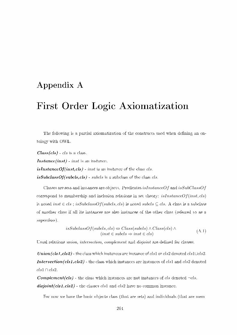
Appendix A
First Order Logic Axiomatization
The following is a partial axiomatization of the constructs used when de�ning an on-
tology with OWL.
Class(cls) - cls is a class.
Instance(inst) - inst is an instance.
isInstanceOf(inst,cls) - inst is an instance of the class cls.
isSubclassOf(subcls,cls) - subcls is a subclass of the class cls.
Classes are sets and instances are objects. Predicates isInstanceOf and isSubClassOf
correspond to membership and inclusion relations in set theory: isInstanceOf(inst, cls)
is noted inst ∈ cls ; isSubclassOf(subcls, cls) is noted subcls ⊆ cls. A class is a subclass
of another class if all its instances are also instances of the other class (referred to as a
superclass).
isSubclassOf(subcls, cls)⇔ Class(subcls) ∧ Class(cls) ∧(inst ∈ subcls⇒ inst ∈ cls)
(A.1)
Usual relations union, intersection, complement and disjoint are de�ned for classes.
Union(cls1,cls2) - the class which instances are instance of cls1 or cls2 denoted cls1∪cls2.
Intersection(cls1,cls2) - the class which instances are instances of cls1 and cls2 denoted
cls1 ∩ cls2.
Complement(cls) - the class which instances are not instances of cls denoted ¬cls.
disjoint(cls1,cls2) - the classes cls1 and cls2 have no common instance.
For now we have the basic objects class (that are sets) and individuals (that are mem-
264
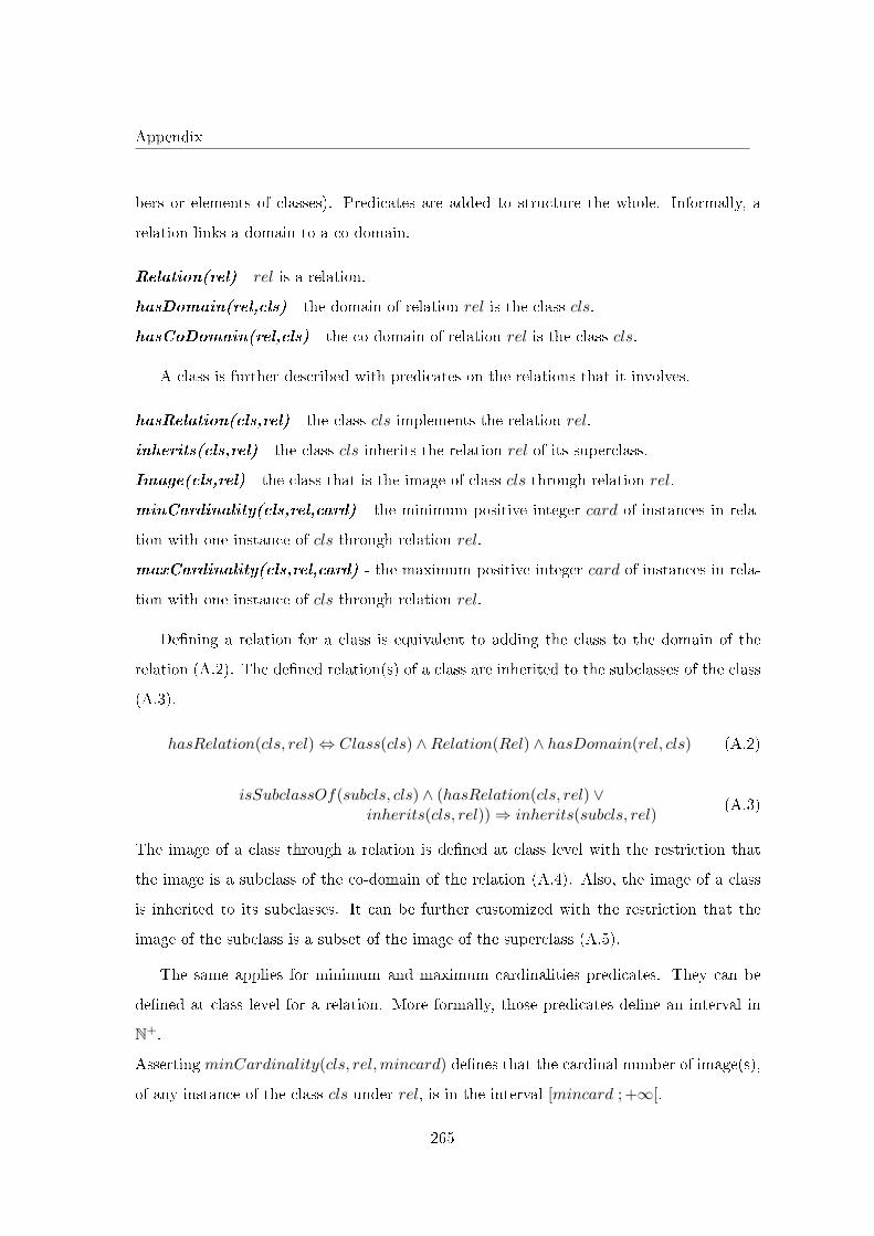
Appendix
bers or elements of classes). Predicates are added to structure the whole. Informally, a
relation links a domain to a co-domain.
Relation(rel) - rel is a relation.
hasDomain(rel,cls) - the domain of relation rel is the class cls.
hasCoDomain(rel,cls) - the co-domain of relation rel is the class cls.
A class is further described with predicates on the relations that it involves.
hasRelation(cls,rel) - the class cls implements the relation rel.
inherits(cls,rel) - the class cls inherits the relation rel of its superclass.
Image(cls,rel) - the class that is the image of class cls through relation rel.
minCardinality(cls,rel,card) - the minimum positive integer card of instances in rela-
tion with one instance of cls through relation rel.
maxCardinality(cls,rel,card) - the maximum positive integer card of instances in rela-
tion with one instance of cls through relation rel.
De�ning a relation for a class is equivalent to adding the class to the domain of the
relation (A.2). The de�ned relation(s) of a class are inherited to the subclasses of the class
(A.3).
hasRelation(cls, rel)⇔ Class(cls) ∧Relation(Rel) ∧ hasDomain(rel, cls) (A.2)
isSubclassOf(subcls, cls) ∧ (hasRelation(cls, rel) ∨inherits(cls, rel))⇒ inherits(subcls, rel)
(A.3)
The image of a class through a relation is de�ned at class level with the restriction that
the image is a subclass of the co-domain of the relation (A.4). Also, the image of a class
is inherited to its subclasses. It can be further customized with the restriction that the
image of the subclass is a subset of the image of the superclass (A.5).
The same applies for minimum and maximum cardinalities predicates. They can be
de�ned at class level for a relation. More formally, those predicates de�ne an interval in
N+.
Asserting minCardinality(cls, rel,mincard) de�nes that the cardinal number of image(s),
of any instance of the class cls under rel, is in the interval [mincard ; +∞[.
265
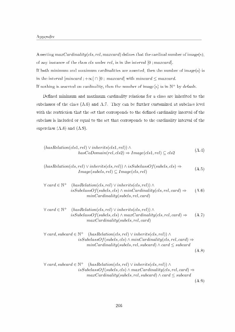
Appendix
AssertingmaxCardinality(cls, rel,maxcard) de�nes that the cardinal number of image(s),
of any instance of the class cls under rel, is in the interval [0 ;maxcard].
If both minimum and maximum cardinalities are asserted, then the number of image(s) is
in the interval [mincard ; +∞[ ∩ [0 ; maxcard] with mincard ≤ maxcard.
If nothing is asserted on cardinality, then the number of image(s) is in N+ by default.
De�ned minimum and maximum cardinality relations for a class are inherited to the
subclasses of the class (A.6) and A.7. They can be further customized at subclass level
with the restriction that the set that corresponds to the de�ned cardinality interval of the
subclass is included or equal to the set that corresponds to the cardinality interval of the
superclass (A.8) and (A.9).
(hasRelation(cls1, rel) ∨ inherits(cls1, rel)) ∧hasCoDomain(rel, cls2)⇒ Image(cls1, rel) ⊆ cls2
(A.4)
(hasRelation(cls, rel) ∨ inherits(cls, rel)) ∧ isSubclassOf(subcls, cls)⇒Image(subcls, rel) ⊆ Image(cls, rel)
(A.5)
∀ card ∈ N+ (hasRelation(cls, rel) ∨ inherits(cls, rel)) ∧isSubclassOf(subcls, cls) ∧minCardinality(cls, rel, card)⇒
minCardinality(subcls, rel, card)(A.6)
∀ card ∈ N+ (hasRelation(cls, rel) ∨ inherits(cls, rel)) ∧isSubclassOf(subcls, cls) ∧maxCardinality(cls, rel, card)⇒
maxCardinality(subcls, rel, card)(A.7)
∀ card, subcard ∈ N+ (hasRelation(cls, rel) ∨ inherits(cls, rel)) ∧isSubclassOf(subcls, cls) ∧minCardinality(cls, rel, card)⇒
minCardinality(subcls, rel, subcard) ∧ card ≤ subcard
(A.8)
∀ card, subcard ∈ N+ (hasRelation(cls, rel) ∨ inherits(cls, rel)) ∧isSubclassOf(subcls, cls) ∧maxCardinality(cls, rel, card)⇒
maxCardinality(subcls, rel, subcard) ∧ card ≤ subcard
(A.9)
266
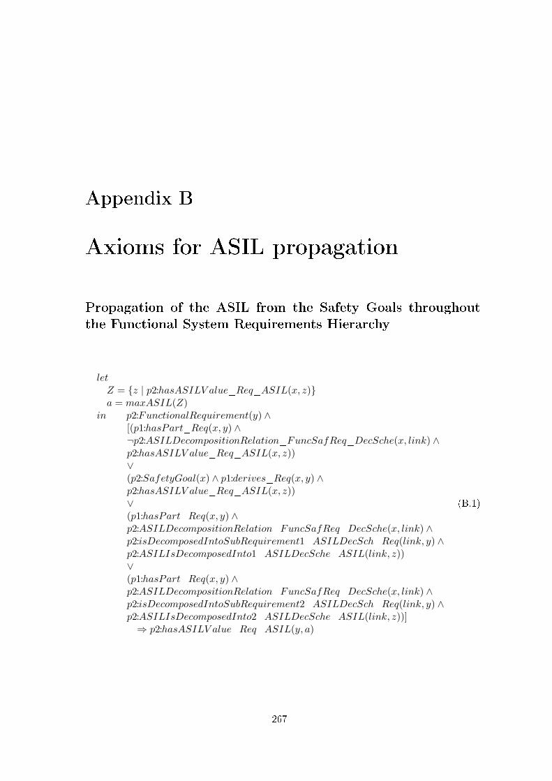
Appendix B
Axioms for ASIL propagation
Propagation of the ASIL from the Safety Goals throughout
the Functional System Requirements Hierarchy
letZ = {z | p2:hasASILV alue_Req_ASIL(x, z)}a = maxASIL(Z)
in p2:FunctionalRequirement(y) ∧[(p1:hasPart_Req(x, y) ∧¬p2:ASILDecompositionRelation_FuncSafReq_DecSche(x, link) ∧p2:hasASILV alue_Req_ASIL(x, z))∨(p2:SafetyGoal(x) ∧ p1:derives_Req(x, y) ∧p2:hasASILV alue_Req_ASIL(x, z))∨(p1:hasPart_Req(x, y) ∧p2:ASILDecompositionRelation_FuncSafReq_DecSche(x, link) ∧p2:isDecomposedIntoSubRequirement1_ASILDecSch_Req(link, y) ∧p2:ASILIsDecomposedInto1_ASILDecSche_ASIL(link, z))∨(p1:hasPart_Req(x, y) ∧p2:ASILDecompositionRelation_FuncSafReq_DecSche(x, link) ∧p2:isDecomposedIntoSubRequirement2_ASILDecSch_Req(link, y) ∧p2:ASILIsDecomposedInto2_ASILDecSche_ASIL(link, z))]⇒ p2:hasASILV alue_Req_ASIL(y, a)
(B.1)
267
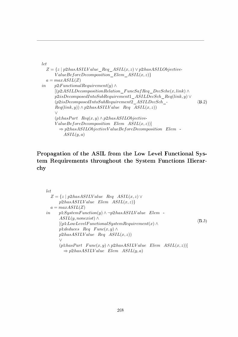
letZ = {z | p2:hasASILV alue_Req_ASIL(x, z) ∨ p2:hasASILObjective-
V alueBeforeDecomposition_Elem_ASIL(x, z)}a = maxASIL(Z)
in p2:FunctionalRequirement(y) ∧[(p2:ASILDecompositionRelation_FuncSafReq_DecSche(x, link) ∧p2:isDecomposedIntoSubRequirement1_ASILDecSch_Req(link, y) ∨(p2:isDecomposedIntoSubRequirement2_ASILDecSch_-Req(link, y)) ∧ p2:hasASILV alue_Req_ASIL(x, z))∨(p1:hasPart_Req(x, y) ∧ p2:hasASILObjective-V alueBeforeDecomposition_Elem_ASIL(x, z))]⇒ p2:hasASILObjectiveV alueBeforeDecomposition_Elem_-ASIL(y, a)
(B.2)
Propagation of the ASIL from the Low Level Functional Sys-
tem Requirements throughout the System Functions Hierar-
chy
letZ = {z | p2:hasASILV alue_Req_ASIL(x, z) ∨
p2:hasASILV alue_Elem_ASIL(x, z)}a = maxASIL(Z)
in p1:SystemFunction(y) ∧ ¬p2:hasASILV alue_Elem_-ASIL(y, nonexist) ∧[(p1:LowLevelFunctionalSystemRequirement(x) ∧p1:deduces_Req_Func(x, y) ∧p2:hasASILV alue_Req_ASIL(x, z))∨(p1:hasPart_Func(x, y) ∧ p2:hasASILV alue_Elem_ASIL(x, z))]⇒ p2:hasASILV alue_Elem_ASIL(y, a)
(B.3)
268

letZ = {z | p2:hasASILObjectiveV alueBeforeDecomposition_Elem_-
ASIL(x, z)}a = maxASIL(Z)
in p1:SystemFunction(y) ∧[(p1:LowLevelFunctionalSystemRequirement(x) ∧p1:deduces_Req_Func(x, y) ∧ p2:hasASILObjectiveV alue-BeforeDecomposition_Elem_ASIL(x, z))∨(p1:hasPart_Func(x, y) ∧ p2:hasASILObjectiveV alue-BeforeDecomposition_Elem_ASIL(x, z))]⇒ p2:hasASILObjectiveV alueBeforeDecomposition_Elem_-ASIL(y, a)
(B.4)
Propagation of the ASIL from the Low Level System Functions
throughout the System Components Hierarchy
letZ = {z | p2:hasASILV alue_Elem_ASIL(x, z)}a = maxASIL(Z)
in (p1:SystemComponent(y) ∨ p1:Interface(y)) ∧¬p2:hasASILV alue_Elem_ASIL(y, nonexist) ∧[p1:LowLevelSystemFunction(x) ∧p1:isAllocatedTo_Func_Comp(x, y) ∧p2:hasASILV alue_Elem_ASIL(x, z)]∨[p1:hasPart_Comp(x, y) ∧ p2:hasASILV alue_Elem_ASIL(x, z)]⇒ p2:hasASILV alue_Elem_ASIL(y, a)
(B.5)
letZ = {z | p2:hasASILObjectiveV alueBeforeDecomposition_Elem_-
ASIL(x, z)}a = maxASIL(Z)
in (p1:SystemComponent(y) ∨ p1:Interface(y)) ∧[(p1:LowLevelSystemFunction(x) ∧p1:isAllocatedTo_Func_Comp(x, y) ∧p2:hasASILObjectiveV alueBeforeDecomposition_Elem_ASIL(x, z))∨(p1:hasPart_Comp(x, y) ∧ p2:hasASILObjectiveV alue-BeforeDecomposition_Elem_ASIL(x, z))]⇒ p2:hasASILObjectiveV alueBeforeDecomposition_Elem_-ASIL(y, a)
(B.6)
269
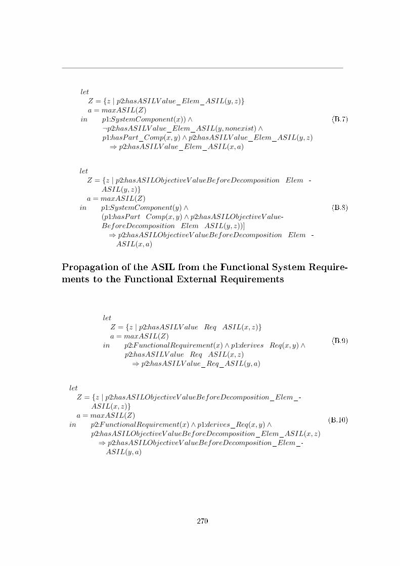
letZ = {z | p2:hasASILV alue_Elem_ASIL(y, z)}a = maxASIL(Z)
in p1:SystemComponent(x)) ∧¬p2:hasASILV alue_Elem_ASIL(y, nonexist) ∧p1:hasPart_Comp(x, y) ∧ p2:hasASILV alue_Elem_ASIL(y, z)⇒ p2:hasASILV alue_Elem_ASIL(x, a)
(B.7)
letZ = {z | p2:hasASILObjectiveV alueBeforeDecomposition_Elem_-
ASIL(y, z)}a = maxASIL(Z)
in p1:SystemComponent(y) ∧(p1:hasPart_Comp(x, y) ∧ p2:hasASILObjectiveV alue-BeforeDecomposition_Elem_ASIL(y, z))]⇒ p2:hasASILObjectiveV alueBeforeDecomposition_Elem_-ASIL(x, a)
(B.8)
Propagation of the ASIL from the Functional System Require-
ments to the Functional External Requirements
letZ = {z | p2:hasASILV alue_Req_ASIL(x, z)}a = maxASIL(Z)
in p2:FunctionalRequirement(x) ∧ p1:derives_Req(x, y) ∧p2:hasASILV alue_Req_ASIL(x, z)⇒ p2:hasASILV alue_Req_ASIL(y, a)
(B.9)
letZ = {z | p2:hasASILObjectiveV alueBeforeDecomposition_Elem_-
ASIL(x, z)}a = maxASIL(Z)
in p2:FunctionalRequirement(x) ∧ p1:derives_Req(x, y) ∧p2:hasASILObjectiveV alueBeforeDecomposition_Elem_ASIL(x, z)⇒ p2:hasASILObjectiveV alueBeforeDecomposition_Elem_-ASIL(y, a)
(B.10)
270
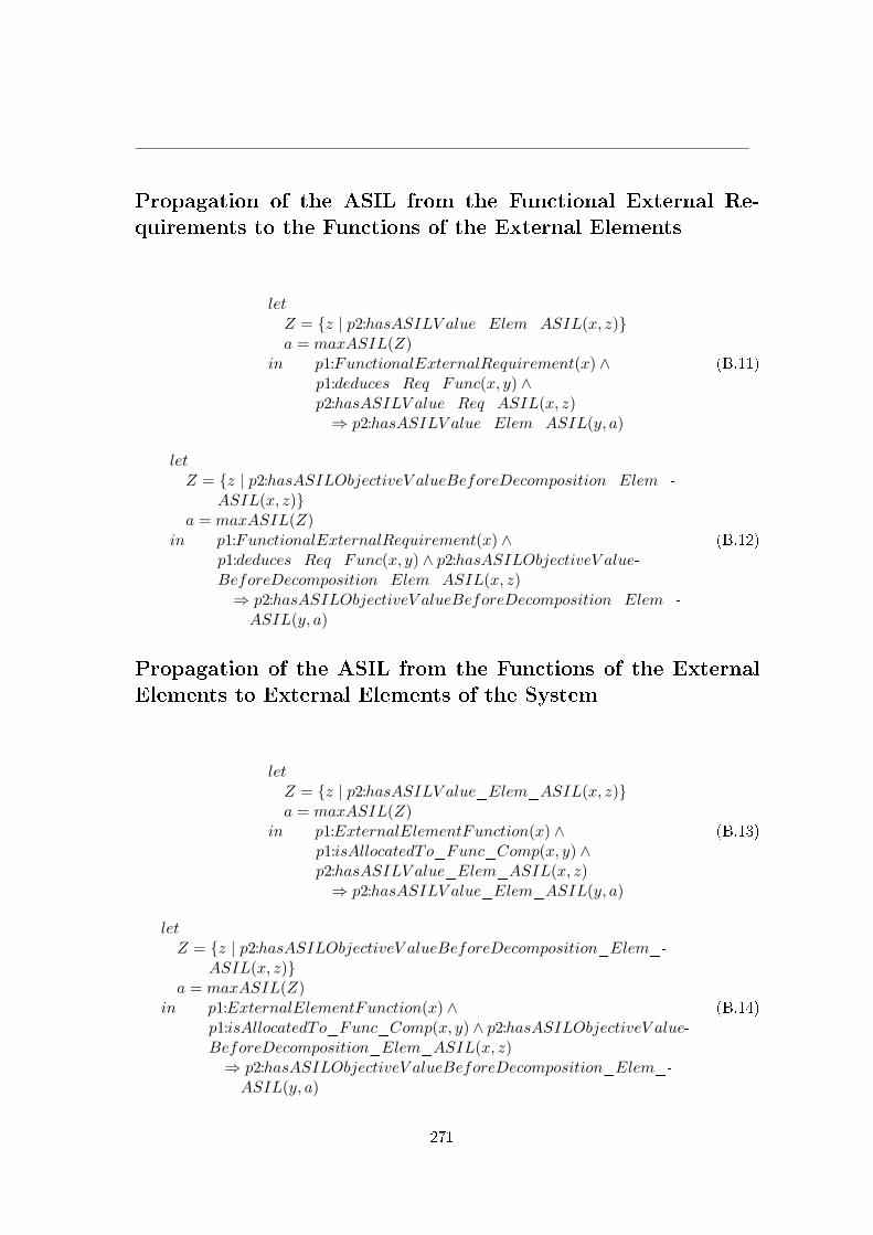
Propagation of the ASIL from the Functional External Re-
quirements to the Functions of the External Elements
letZ = {z | p2:hasASILV alue_Elem_ASIL(x, z)}a = maxASIL(Z)
in p1:FunctionalExternalRequirement(x) ∧p1:deduces_Req_Func(x, y) ∧p2:hasASILV alue_Req_ASIL(x, z)⇒ p2:hasASILV alue_Elem_ASIL(y, a)
(B.11)
letZ = {z | p2:hasASILObjectiveV alueBeforeDecomposition_Elem_-
ASIL(x, z)}a = maxASIL(Z)
in p1:FunctionalExternalRequirement(x) ∧p1:deduces_Req_Func(x, y) ∧ p2:hasASILObjectiveV alue-BeforeDecomposition_Elem_ASIL(x, z)⇒ p2:hasASILObjectiveV alueBeforeDecomposition_Elem_-ASIL(y, a)
(B.12)
Propagation of the ASIL from the Functions of the External
Elements to External Elements of the System
letZ = {z | p2:hasASILV alue_Elem_ASIL(x, z)}a = maxASIL(Z)
in p1:ExternalElementFunction(x) ∧p1:isAllocatedTo_Func_Comp(x, y) ∧p2:hasASILV alue_Elem_ASIL(x, z)⇒ p2:hasASILV alue_Elem_ASIL(y, a)
(B.13)
letZ = {z | p2:hasASILObjectiveV alueBeforeDecomposition_Elem_-
ASIL(x, z)}a = maxASIL(Z)
in p1:ExternalElementFunction(x) ∧p1:isAllocatedTo_Func_Comp(x, y) ∧ p2:hasASILObjectiveV alue-BeforeDecomposition_Elem_ASIL(x, z)⇒ p2:hasASILObjectiveV alueBeforeDecomposition_Elem_-ASIL(y, a)
(B.14)
271

Ofaina TAOFIFENUA
ONTOLOGY CENTRIC DESIGNPROCESS
Sharing a Conceptualization
Résumé :Dans le marché mondial fortement concurrentiel, un constructeur automobile doit o�rir à ses clients desservices innovants, respectueux de l'environnement et sûrs de fonctionnement. Tout cela doit être fait àdes coûts très compétitifs tout en respectant des réglementations et des délais de plus en plus stricts. Cestravaux répondent à ces dé�s et visent à améliorer le processus de conception des systèmes mécatroniquescritiques automobile. Ils montrent que l'utilisation de modèles formels et informels peuvent se rapporterà un modèle sémantique commun, i.e., une ontologie système et sécurité, qui permet d'assurer lacohérence du processus de conception tout en respectant la norme ISO 26262. Les concepts de cestravaux ont été appliquées sur un système de freinage régénératif hybride intégré dans un véhiculeélectrique. L'application a démontré que l'ontologie réalisée permet d'enregistrer l'information produitelors de la conception et que l'utilisation d'ontologies permet e�ectivement de détecter les incohérencessémantiques ce qui améliore la qualité des informations de conception, favorise la réutilisation et assurela conformité à l'ISO 26262.
Mots clés :Ingénierie des sytèmes, sécurité fonctionnelle, ISO 26262, ontologie, processus de conception
Abstract :In the strongly competitive worldwide market of today, a car manufacturer has to o�er to its customersrelevant, innovative, reliable, environment friendly and safe services. All this must be done at verycompetitive costs while complying with more and more stringent regulations and tighter deadlines. Thiswork addresses these challenges and aims at improving the design process for automotive safety criticalmechatronics systems. It shows that the use of formal and informal models can commit to a commonsemantic model, i.e., a system and safety ontology, that enables to ensure the consistency of the wholedesign process and compliance with standard ISO 26262. The concepts in this work have been appliedon a regenerative hybrid braking system integrated into an electrical vehicle. It demonstrated that therealized ontology enables to record the information produced during design and that using ontologiese�ectively enables to detect semantic inconsistencies which improves design information quality, promotesreuse and ensures ISO 26262 compliance.
Keywords :Systems engineering, functional safety, ISO 26262, ontology, design process

![[PPT]Regenerative Braking Systems and their functions · Web viewHow Does Regenerative Braking Work? Regular brakes waste large amounts of useable energy6 Regenerative Braking systems](https://img.pdfslide.net/doc/110x75/5ae8634b7f8b9aee078f7805/pptregenerative-braking-systems-and-their-functions-viewhow-does-regenerative.jpg)

![REGENERATIVE BRAKING SYSTEM IN ELECTRIC VEHICLES · REGENERATIVE BRAKING SYSTEM IN ELECTRIC VEHICLES ... REGENERATIVE BRAKING SYSTEM ... Regenerative action during braking[9]](https://img.pdfslide.net/doc/110x75/5adccef67f8b9a1a088c7cf0/regenerative-braking-system-in-electric-vehicles-braking-system-in-electric-vehicles.jpg)