Embed Size (px)
Citation preview

ONVIF™ – 1 – ONVIF Core Spec. – Ver. 2.10
ONVIF™ Core Specification
Version 2.1 June, 2011
ONVIF™ – 2 – ONVIF Core Spec. – Ver. 2.10
2008-2011 by ONVIF: Open Network Video Interface Forum Inc.. All rights reserved. Recipients of this document may copy, distribute, publish, or display this document so long as this copyright notice, license and disclaimer are retained with all copies of the document. No license is granted to modify this document. THIS DOCUMENT IS PROVIDED "AS IS," AND THE CORPORATION AND ITS MEMBERS AND THEIR AFFILIATES, MAKE NO REPRESENTATIONS OR WARRANTIES, EXPRESS OR IMPLIED, INCLUDING BUT NOT LIMITED TO, WARRANTIES OF MERCHANTABILITY, FITNESS FOR A PARTICULAR PURPOSE, NON-INFRINGEMENT, OR TITLE; THAT THE CONTENTS OF THIS DOCUMENT ARE SUITABLE FOR ANY PURPOSE; OR THAT THE IMPLEMENTATION OF SUCH CONTENTS WILL NOT INFRINGE ANY PATENTS, COPYRIGHTS, TRADEMARKS OR OTHER RIGHTS. IN NO EVENT WILL THE CORPORATION OR ITS MEMBERS OR THEIR AFFILIATES BE LIABLE FOR ANY DIRECT, INDIRECT, SPECIAL, INCIDENTAL, PUNITIVE OR CONSEQUENTIAL DAMAGES, ARISING OUT OF OR RELATING TO ANY USE OR DISTRIBUTION OF THIS DOCUMENT, WHETHER OR NOT (1) THE CORPORATION, MEMBERS OR THEIR AFFILIATES HAVE BEEN ADVISED OF THE POSSIBILITY OF SUCH DAMAGES, OR (2) SUCH DAMAGES WERE REASONABLY FORESEEABLE, AND ARISING OUT OF OR RELATING TO ANY USE OR DISTRIBUTION OF THIS DOCUMENT. THE FOREGOING DISCLAIMER AND LIMITATION ON LIABILITY DO NOT APPLY TO, INVALIDATE, OR LIMIT REPRESENTATIONS AND WARRANTIES MADE BY THE MEMBERS AND THEIR RESPECTIVE AFFILIATES TO THE CORPORATION AND OTHER MEMBERS IN CERTAIN WRITTEN POLICIES OF THE CORPORATION.
ONVIF™ – 3 – ONVIF Core Spec. – Ver. 2.10
CONTENTS
1 Scope 9
2 Normative references 10
3 Terms and Definitions 11
3.1 Definitions......................................................................................................................11
3.2 Abbreviations ................................................................................................................12
4 Overview 14
4.1 Web Services ................................................................................................................14
4.2 IP configuration .............................................................................................................15
4.3 Device discovery ...........................................................................................................15
4.4 Device Types ................................................................................................................15
4.5 Device management .....................................................................................................16 4.5.1 Capabilities ...............................................................................................................16 4.5.2 Network.....................................................................................................................16 4.5.3 System......................................................................................................................17 4.5.4 Retrieval of System Information................................................................................17 4.5.5 Firmware Upgrade ....................................................................................................17 4.5.6 System Restore ........................................................................................................18 4.5.7 Security .....................................................................................................................18
4.6 Event handling ..............................................................................................................18
4.7 Security .........................................................................................................................19
5 Web Services framework 20
5.1 Services overview .........................................................................................................20 5.1.1 Services requirements ..............................................................................................20
5.2 WSDL overview.............................................................................................................21
5.3 Namespaces .................................................................................................................21
5.4 Types.............................................................................................................................22
5.5 Messages......................................................................................................................23
5.6 Operations.....................................................................................................................23 5.6.1 One-way operation type............................................................................................24 5.6.2 Request-response operation type.............................................................................25
5.7 Port Types.....................................................................................................................25
5.8 Binding ..........................................................................................................................26
5.9 Ports ..............................................................................................................................26
5.10 Services.........................................................................................................................26
5.11 Error handling................................................................................................................26 5.11.1 Protocol errors ......................................................................................................26 5.11.2 SOAP errors .........................................................................................................27
5.12 Security .........................................................................................................................30 5.12.1 User-based access control...................................................................................32 5.12.2 Username token profile ........................................................................................33
6 IP configuration 35
7 Device discovery 36
ONVIF™ – 4 – ONVIF Core Spec. – Ver. 2.10
7.1 General..........................................................................................................................36
7.2 Modes of operation .......................................................................................................36
7.3 Discovery definitions .....................................................................................................36 7.3.1 Endpoint reference ...................................................................................................36 7.3.2 Hello..........................................................................................................................37 7.3.3 Probe and Probe Match............................................................................................39 7.3.4 Resolve and Resolve Match .....................................................................................39 7.3.5 Bye............................................................................................................................39 7.3.6 SOAP Fault Messages .............................................................................................39
7.4 Remote discovery extensions .......................................................................................40 7.4.1 Network scenarios ....................................................................................................40 7.4.2 Discover proxy ..........................................................................................................42 7.4.3 Remote Hello and Probe behaviour..........................................................................43 7.4.4 Client behaviour........................................................................................................44 7.4.5 Security .....................................................................................................................45
8 Device management 47
8.1 Capabilities....................................................................................................................47 8.1.1 Get WSDL URL.........................................................................................................47 8.1.2 Capability exchange .................................................................................................47
8.2 Network .........................................................................................................................52 8.2.1 Get hostname ...........................................................................................................52 8.2.2 Set hostname............................................................................................................52 8.2.3 Set hostname from DHCP ........................................................................................53 8.2.4 Get DNS settings ......................................................................................................53 8.2.5 Set DNS settings ......................................................................................................54 8.2.6 Get NTP settings ......................................................................................................54 8.2.7 Set NTP settings.......................................................................................................55 8.2.8 Get dynamic DNS settings........................................................................................55 8.2.9 Set dynamic DNS settings ........................................................................................56 8.2.10 Get network interface configuration......................................................................57 8.2.11 Set network interface configuration ......................................................................58 8.2.12 Get network protocols ..........................................................................................59 8.2.13 Set network protocols...........................................................................................59 8.2.14 Get default gateway..............................................................................................60 8.2.15 Set default gateway..............................................................................................60 8.2.16 Get zero configuration ..........................................................................................61 8.2.17 Set zero configuration ..........................................................................................61 8.2.18 Get IP address filter..............................................................................................62 8.2.19 Set IP address filter ..............................................................................................62 8.2.20 Add an IP filter address ........................................................................................63 8.2.21 Remove an IP filter address .................................................................................63 8.2.22 IEEE 802.11 configuration....................................................................................64
8.3 System ..........................................................................................................................68 8.3.1 Device Information....................................................................................................68 8.3.2 Get System URIs ......................................................................................................69 8.3.3 Backup ......................................................................................................................69 8.3.4 Restore .....................................................................................................................70 8.3.5 Start system restore..................................................................................................70 8.3.6 Get system date and time.........................................................................................71 8.3.7 Set system date and time .........................................................................................72 8.3.8 Factory default ..........................................................................................................72 8.3.9 Firmware upgrade.....................................................................................................73 8.3.10 Start firmware upgrade.........................................................................................74 8.3.11 Get system logs....................................................................................................74 8.3.12 Get support information........................................................................................75 8.3.13 Reboot ..................................................................................................................76 8.3.14 Get scope parameters..........................................................................................76
ONVIF™ – 5 – ONVIF Core Spec. – Ver. 2.10
8.3.15 Set scope parameters ..........................................................................................77 8.3.16 Add scope parameters .........................................................................................77 8.3.17 Remove scope parameters ..................................................................................77 8.3.18 Get discovery mode..............................................................................................78 8.3.19 Set discovery mode..............................................................................................78 8.3.20 Get remote discovery mode .................................................................................79 8.3.21 Set remote discovery mode..................................................................................79 8.3.22 Get remote DP addresses....................................................................................80 8.3.23 Set remote DP addresses ....................................................................................80
8.4 Security .........................................................................................................................81 8.4.1 Get access policy......................................................................................................81 8.4.2 Set access policy ......................................................................................................81 8.4.3 Get users ..................................................................................................................82 8.4.4 Create users .............................................................................................................82 8.4.5 Delete users..............................................................................................................83 8.4.6 Set users settings .....................................................................................................83 8.4.7 IEEE 802.1X configuration........................................................................................84 8.4.8 Create self-signed certificate ....................................................................................88 8.4.9 Get certificates..........................................................................................................89 8.4.10 Get CA certificates................................................................................................89 8.4.11 Get certificate status.............................................................................................89 8.4.12 Set certificate status .............................................................................................90 8.4.13 Get certificate request ..........................................................................................90 8.4.14 Get client certificate status ...................................................................................91 8.4.15 Set client certificate status....................................................................................91 8.4.16 Load device certificate..........................................................................................92 8.4.17 Load device certificates in conjunction with its private key ..................................93 8.4.18 Get certificate information request .......................................................................93 8.4.19 Load CA certificates .............................................................................................94 8.4.20 Delete certificate...................................................................................................95 8.4.21 Get remote user....................................................................................................95 8.4.22 Set remote user ....................................................................................................96 8.4.23 Get endpoint reference.........................................................................................97
8.5 Input/Output (I/O) ..........................................................................................................97 8.5.1 Get relay outputs ......................................................................................................97 8.5.2 Set relay output settings ...........................................................................................97 8.5.3 Trigger relay output...................................................................................................98 8.5.4 Auxiliary operation ....................................................................................................99
8.6 Service specific fault codes...........................................................................................99
9 Event handling 106
9.1 Basic Notification Interface..........................................................................................106 9.1.1 Introduction .............................................................................................................106 9.1.2 Requirements..........................................................................................................107
9.2 Real-time Pull-Point Notification Interface ..................................................................108 9.2.1 Create pull point subscription .................................................................................110 9.2.2 Pull messages.........................................................................................................110
9.3 Notification Streaming Interface..................................................................................111
9.4 Properties....................................................................................................................111 9.4.1 Property Example ...................................................................................................111
9.5 Notification Structure...................................................................................................112 9.5.1 Notification information ...........................................................................................112 9.5.2 Message Format.....................................................................................................113 9.5.3 Property example, continued..................................................................................114 9.5.4 Message Description Language .............................................................................116 9.5.5 Message Content Filter...........................................................................................117
9.6 Synchronization Point .................................................................................................118
ONVIF™ – 6 – ONVIF Core Spec. – Ver. 2.10
9.7 Topic Structure............................................................................................................119 9.7.1 ONVIF Topic Namespace.......................................................................................119 9.7.2 Topic Type Information ...........................................................................................120 9.7.3 Topic Filter ..............................................................................................................120
9.8 Get event properties....................................................................................................121
9.9 Capabilities..................................................................................................................122
9.10 SOAP Fault Messages................................................................................................123
9.11 Notification example....................................................................................................123 9.11.1 GetEventPropertiesRequest...............................................................................123 9.11.2 GetEventPropertiesResponse............................................................................123 9.11.3 CreatePullPointSubscription...............................................................................124 9.11.4 CreatePullPointSubscriptionResponse ..............................................................125 9.11.5 PullMessagesRequest........................................................................................126 9.11.6 PullMessagesResponse.....................................................................................126 9.11.7 UnsubscribeRequest ..........................................................................................127 9.11.8 UnsubscribeResponse .......................................................................................127
9.12 Service specific fault codes.........................................................................................128
10 Security 128
10.1 Transport level security ...............................................................................................128 10.1.1 Supported cipher suites......................................................................................129 10.1.2 Server authentication .........................................................................................129 10.1.3 Client authentication...........................................................................................129
10.2 Message level security................................................................................................129
10.3 IEEE 802.1X................................................................................................................130
Annex A (informative) Notification topics 131
A.1 Media configuration topics ..........................................................................................131 A.1.1 Profile......................................................................................................................131 A.1.2 VideoSourceConfiguration......................................................................................131 A.1.3 AudioSourceConfiguration......................................................................................131 A.1.4 VideoEncoderConfiguration....................................................................................132 A.1.5 AudioEncoderConfiguration....................................................................................132 A.1.6 VideoAnalyticsConfiguration...................................................................................132 A.1.7 PTZConfiguration....................................................................................................132 A.1.8 MetaDataConfiguration...........................................................................................132 A.1.9 Device management topics ....................................................................................132 A.1.10 Relay ..................................................................................................................133 A.1.11 PTZ Controller Topics.........................................................................................133
Annex B (normative) Capability List of GetCapabilities 135
Bibliography 140
ONVIF™ – 7 – ONVIF Core Spec. – Ver. 2.10
Contributors
Version 1
Christian Gehrmann
(Ed.) Axis Communications AB
Mikael Ranbro Axis Communications AB
Johan Nyström Axis Communications AB
Ulf Olsson Axis Communications AB
Göran Haraldsson Axis Communications AB
Daniel Elvin Axis Communications AB
Hans Olsen Axis Communications AB
Martin Rasmusson Axis Communications AB
Stefan Andersson (co Ed.)
Axis Communications AB
Alexander Neubeck Bosch Security Systems
Susanne Kinza Bosch Security Systems
Markus Wierny Bosch Security Systems
Rainer Bauereiss Bosch Security Systems
Masashi Tonomura (co Ed.)
Sony Corporation
Norio Ishibashi Sony Corporation
Yoichi Kasahara
Sony Corporation
Yoshiyuki Kunito Sony Corporation
Version 2
Toshihiro Shimizu Panasonic
Manabu Nakamura Panasonic
Hasan Timucin Ozdemir Panasonic
Hiroaki Ootake Panasonic
Young Hoon OK ITX
Sekrai Hong Samsung
Gero Bäse Siemens
Michio Hirai Sony Corporation
Akihiro Hokimoto Sony Corporation
Kazunori Sakaki Sony Corporation
Masashi Tonomura Sony Corporation
Stefan Andersson Axis Communications AB
Christian Gehrmann Axis Communications AB
Willy Sagefalk Axis Communications AB
Mikael Ranbro Axis Communications AB
Ted Hartzell Axis Communications AB
Rainer Bauereiss Bosch Security Systems
Hans Busch (Ed.)
Bosch Security Systems
Susanne Kinza (co Ed.)
Bosch Security Systems
Dieu Thanh Nguyen Bosch Security Systems
Antonie van Woerdekom Bosch Security Systems
Shinichi Hatae Canon Inc
Takahiro Iwasaki Canon Inc
Takeshi Asahi Hitachi Ltd
Colin Caughie IndigoVision Ltd
Heather Logan IndigoVision Ltd
ONVIF™ – 8 – ONVIF Core Spec. – Ver. 2.10
INTRODUCTION
The goal of this specification is to provide the common base for a fully interoperable network implementation comprised of products from different network vendors. This standard describes the network model, interfaces, data types and data exchange patterns. The standard reuses existing relevant standards where available, and introduces new specifications only where necessary.
This is the ONVIF core specification. It is accompanied by a set of computer readable interface definitions:
ONVIF Schema [ONVIF Schema]
ONVIF Device Service WSDL [ONVIF DM WSDL]
ONVIF Event Service WSDL [ONVIF Event WSDL]
ONVIF Topic Namespace XML [ONVIF Topic Namespace]
The purpose of this document is to define the ONVIF specification framework, and is divided into the following sections:
Specification Overview: Gives an overview of the different specification parts and how they are related to each other.
Web Services Frame Work: Offers a brief introduction to Web Services and the Web Services basis for the ONVIF specifications.
IP Configuration: Defines the ONVIF network IP configuration requirements.
Device Discovery: Describes how devices are discovered in local and remote networks.
Device Management: Defines the configuration of basics like network and security related settings.
Event Handling: Defines how to subscribe to and receive notifications (events) from a device.
Security Section: Defines the transport and message level security requirements on ONVIF compliant implementations.
ONVIF™ – 9 – ONVIF Core Spec. – Ver. 2.10
1 Scope
This specification defines procedures for communication between network clients and devices. This new set of specifications makes it possible to build e.g. network video systems with devices and receivers from different manufacturers using common and well defined interfaces. The functions defined in this specification covers discovery, device management and event framework.
Supplementary dedicated services as e.g. media configuration, real-time streaming of audio and video, Pan, Tilt and Zoom (PTZ) control, video analytics as well as control, search and replay of recordings are defined in separate documents.
The management and control interfaces defined in this standard are described as Web Services. This standard also contains full XML schema and Web Service Description Language (WSDL) definitions.
In order to offer full plug-and-play interoperability, the standard defines procedures for device discovery. The device discovery mechanisms in the standard are based on the WS-Discovery specification with extensions.
ONVIF™ – 10 – ONVIF Core Spec. – Ver. 2.10
2 Normative references
RSA Laboratories, PKCS #10 v1.7: Certification Request Syntax Standard, RSA Laboratories
<ftp://ftp.rsasecurity.com/pub/pkcs/pkcs-10/pkcs-10v1_7.pdf>
FIPS 180-2, SECURE HASH STANDARD
<http://csrc.nist.gov/publications/fips/fips180-2/fips180-2.pdf>
IEEE 1003.1, The Open Group Base Specifications Issue 6, IEEE Std 1003.1, 2004 Edition
< http://pubs.opengroup.org/onlinepubs/009695399/>
IETF RFC 2131, Dynamic Host Configuration Protocol
<http://www.ietf.org/rfc/rfc2131.txt>
IETF RFC 2136, Dynamic Updates in the Domain Name System (DNS UPDATE)
<http://www.ietf.org/rfc/rfc2136.txt>
IETF RFC 2246, The TLS Protocol Version 1.0
<http://www.ietf.org/rfc/rfc2246.txt>
IETF RFC 2616, Hypertext Transfer Protocol -- HTTP/1.1
<http://www.ietf.org/rfc/rfc2616.txt>
IETF RFC 2617, HTTP Authentication: Basic and Digest Access Authentication
<http://www.ietf.org/rfc/rfc2617.txt>
IETF RFC 2782, A DNS RR for specifying the location of services (DNS SRV)
<http://www.ietf.org/rfc/rfc2782.txt>
IETF RFC 2818, HTTP over TLS
<http://www.ietf.org/rfc/rfc2818.txt>
IETF RFC 3268, Advanced Encryption Standard (AES) Cipher suites for Transport Layer Security (TLS)
<http://www.ietf.org/rfc/rfc3268.txt>
IETF RFC 3315, Dynamic Host Configuration Protocol for IPv6 (DHCPv6)
<http://www.ietf.org/rfc/rfc3315.txt>
IETF RFC 3548, The Base16, Base32, and Base64 Data Encodings
<http://www.ietf.org/rfc/rfc3548.txt>
IETF RFC 3927, Dynamic Configuration of IPv4 Link-Local Addresses
<http://www.ietf.org/rfc/rfc3927.txt>
IETF RFC 3986, Uniform Resource Identifier (URI): Generic Syntax
<http://www.ietf.org/rfc/rfc3986.txt>
IETF RFC 4122, A Universally Unique IDentifier (UUID) URN Namespace
<http://www.ietf.org/rfc/rfc4122.txt>
IETF RFC 4346, The Transport Layer Security (TLS) Protocol Version 1.1
<http://www.ietf.org/rfc/rfc4346.txt>
IETF 4702, The Dynamic Host Configuration Protocol (DHCP) Client Fully Qualified Domain Name (FQDN) Option
<http://www.ietf.org/rfc/rfc4702.txt>
IETF 4861, Neighbor Discovery for IP version 6 (IPv6)
<http://www.ietf.org/rfc/rfc4861.txt>
IETF 4862, IPv6 Stateless Address Auto configuration
<http://www.ietf.org/rfc/rfc4862.txt>
IETF 5246, The Transport Layer Security (TLS) Protocol Version 1.2
<http://www.ietf.org/rfc/rfc5246.txt>
ONVIF™ – 11 – ONVIF Core Spec. – Ver. 2.10 W3C SOAP Message Transmission Optimization Mechanism,
<http://www.w3.org/TR/soap12-mtom/>
W3C SOAP 1.2, Part 1, Messaging Framework
<http://www.w3.org/TR/soap12-part1/>
W3C SOAP Version 1.2 Part 2: Adjuncts (Second Edition)
<http://www.w3.org/TR/2007/REC-soap12-part2-20070427/>
W3C Web Services Addressing 1.0 – Core
<http://www.w3.org/TR/ws-addr-core/>
WS-I Basic Profile Version 2.0
< http://www.ws-i.org/Profiles/BasicProfile-2.0-2010-11-09.html>
OASIS Web Services Base Notification 1.3
<http://docs.oasis-open.org/wsn/wsn-ws_base_notification-1.3-spec-os.pdf>
XMLSOAP, Web Services Dynamic Discovery (WS-Discovery)”, J. Beatty et al., April 2005.
<http://specs.xmlsoap.org/ws/2005/04/discovery/ws-discovery.pdf>
OASIS Web Services Security: SOAP Message Security 1.1 (WS-Security 2004)
<http://www.oasis-open.org/committees/download.php/16790/wss-v1.1-spec-os-SOAPMessageSecurity.pdf>
OASIS Web Services Topics 1.3
<http://docs.oasis-open.org/wsn/wsn-ws_topics-1.3-spec-os.pdf>
OASIS Web Services Security UsernameToken Profile 1.0
<http://docs.oasis-open.org/wss/2004/01/oasis-200401-wss-username-token-profile-1.0.pdf>
W3C Web Services Description Language (WSDL) 1.1
<http://www.w3.org/TR/wsdl>
W3C XML Schema Part 1: Structures Second Edition
<http://www.w3.org/TR/xmlschema-1/>
W3C XML Schema Part 2: Datatypes Second Edition
<http://www.w3.org/TR/xmlschema-2/>
W3C XML-binary Optimized Packaging
<http://www.w3.org/TR/2005/REC-xop10-20050125/>
IEEE 802.11, Part 11: Wireless LAN Medium Access Control (MAC) and Physical Layer (PHY) Specifications
<http://standards.ieee.org/getieee802/download/802.11-2007.pdf>
IEEE 802.1X, Port-Based Network Access Control
<http://standards.ieee.org/getieee802/download/802.1X-2004.pdf>
3 Terms and Definitions
3.1 Definitions
Ad-hoc network Often used as a vernacular term for an independent basic service set, as defined in [IEEE 802.11-2007]. A set of IEEE802.11 stations that have successfully joined in a common network, see [IEEE 802.11-2007].
Basic Service Set
Capability The capability commands allows a client to ask for the services provided
An IEEE 802.11 network that includes an access point, as defined in [IEEE 802.11-2007].
by a device.
Infrastructure network
Network Video Transmitter (NVT)
Network video server (an IP network camera or an encoder device, for example) that sends media data over an IP network to a client.
Network Video Display (NVD)
Network video receiver (an IP network video monitor, for example) that receives media data over an IP network from e.g. an NVT.
ONVIF™ – 12 – ONVIF Core Spec. – Ver. 2.10
Network Video Storage (NVS)
A device that records media and metadata received from a streaming device, such as an NVT, over an IP network to a permanent storage medium. The NVS also enables clients to review the stored data
Network Video Analytics (NVA)
A device that performs analysis on data received from a streaming device, such as an NVT, or a storage device, such as an NVS.
PKCS Refers to a group of Public Key Cryptography Standards devised and published by RSA Security.
Pre Shared Key A static key that is distributed to the device.
PullPoint Resource for pulling messages. By pulling messages, notifications are not blocked by firewalls.
Remote Discovery Proxy (Remote DP)
The remote DP allows a NVT to register at the remote DP and at the NVC to find registered NVTs through the remote DP even if the NVC and NVT resides in different administrative network domains.
Service Set ID The identity of an [IEEE 802.11-2007] wireless network.
Wi-Fi Protected Access A certification program created by the Wi-Fi Alliance to indicate compliance with the security protocol covered by the program.
3.2 Abbreviations
ASN Abstract Syntax Notation BSSID Basic Service Set Identification CA Certificate Authority CBC Cipher-Block Chaining CCMP Counter mode with Cipher-block chaining Message authentication code Protocol DER Distinguished Encoding Rules DHCP Dynamic Host Configuration Protocol DM Device Management DNS Domain Name Server DP Discovery Proxy GW Gateway HTTP Hypertext Transfer Protocol HTTPS Hypertext Transfer Protocol over Secure Socket Layer IO, I/O Input/Output IP Internet Protocol IPv4 Internet Protocol Version 4 IPv6 Internet Protocol Version 6 MTOM Message Transmission Optimization Mechanism NAT Network Address Translation NFC Near Field Communication NTP Network Time Protocol NVA Network Video Analytics Device NVC Network Video Client NVD Network Video Display NVT Network Video Transmitter NVS Network Video Storage Device OASIS Organization for the Advancement of Structured Information Standards ONVIF Open Network Video Interface Forum POSIX Portable Operating System Interface PKCS Public Key Cryptography Standards PSK Pre Shared Key PTZ Pan/Tilt/Zoom REL Rights Expression Language RSA Rivest ,Sharmir and Adleman SAML Security Assertion Markup Language SHA Secure Hash Algorithm SOAP Simple Object Access Protocol SSID Service Set ID TCP Transmission Control Protocol TLS Transport Layer Security

ONVIF™ – 13 – ONVIF Core Spec. – Ver. 2.10
TKIP Temporal Key Integrity Protocol TTL Time To Live UDDI Universal Description, Discovery and Integration UDP User Datagram Protocol URI Uniform Resource Identifier URN Uniform Resource Name USB Universal Serial Bus UTC Coordinated Universal Time UTF Unicode Transformation Format UUID Universally Unique Identifier WDR Wide Dynamic Range WPA Wi-Fi Protected Access WS Web Services WSDL Web Services Description Language WS-I Web Services Interoperability XML eXtensible Markup Language
ONVIF™ – 14 – ONVIF Core Spec. – Ver. 2.10
4 Overview
This specification originated from network video use cases covering both local and wide area network scenarios and has been extended to cover generic IP device use cases. The specification defines a core set of interface functions for configuration and operation of network devices by defining their server side interfaces.
This standard covers device discovery, device configuration as well as an event framework.
All services share a common XML schema and all data types are provided in [ONVIF Schema]. The different services are defined in the respective sections and service WSDL documents.
4.1 Web Services
The term Web Services is the name of a standardized method of integrating applications using open, platform independent Web Services standards such as XML, SOAP 1.2 [Part 1] and WSDL1.1 over an IP network. XML is used as the data description syntax, SOAP is used for message transfer and WSDL is used for describing the services.
This framework is built upon Web Services standards. All configuration services defined in the standard are expressed as Web Services operations and defined in WSDL with HTTP as the underlying transport mechanism.
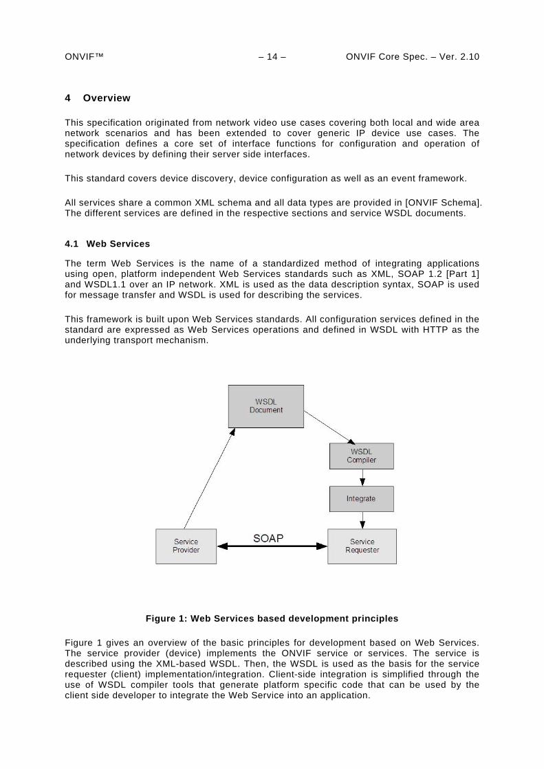
Figure 1: Web Services based development principles
Figure 1 gives an overview of the basic principles for development based on Web Services. The service provider (device) implements the ONVIF service or services. The service is described using the XML-based WSDL. Then, the WSDL is used as the basis for the service requester (client) implementation/integration. Client-side integration is simplified through the use of WSDL compiler tools that generate platform specific code that can be used by the client side developer to integrate the Web Service into an application.
ONVIF™ – 15 – ONVIF Core Spec. – Ver. 2.10 The Web Service provider and requester communicate using the SOAP message exchange protocol. SOAP is a lightweight, XML-based messaging protocol used to encode the information in a Web Service request and in a response message before sending them over a network. SOAP messages are independent of any operating system or protocol and may be transported using a variety of Internet protocols. This ONVIF standard defines conformant transport protocols for the SOAP messages for the described Web Services.
The Web Service overview section introduces into the general ONVIF service structure, the command definition syntax in the specification, error handling principles and the adopted Web Service security mechanisms.
To ensure interoperability, all ONVIF services follow the Web Services Interoperability Organization (WS-I) basic profile 2.0 recommendations and use the document/literal wrapped pattern.
4.2 IP configuration
The IP configuration section defines the IP configuration compliance requirements and recommendations. IP configuration includes:
IP network communication capability
Static IP configuration
Dynamic IP configuration
4.3 Device discovery
The configuration interfaces defined in this standard are Web Services interfaces that are based on the WS-Discovery standard. This use of this standard makes it possible to reuse a suitable existing Web Service discovery framework, instead of requiring a completely new service or service addressing definition.
This standard introduces a specific discovery behaviour suitable for e.g. video surveillance purposes. For example, a fully interoperable discovery requires a well defined service definition and a service searching criteria. The specification covers device type and scopes definitions in order to achieve this.
A successful discovery provides the device service address. Once a client has the device service address it can receive detailed device information through the device service, see section 4.5 below.
In addition to the standard web services discovery protocol this specification supports remote discovery proxies to find registered devices through the remote discovery proxy even if the client and the device reside in different administrative network domains.
4.4 Device Types
The device type signals the primary function of a device. Device types are defined in the device type specifications. These are released per type. Types defined include:
Network Video Transmitter (NVT)
Network Video Display (NVD)
ONVIF™ – 16 – ONVIF Core Spec. – Ver. 2.10
Network Video Storage (NVS)
Network Video Analytics (NVA)
For each device type a number of services are mandatory which are defined in the respective definition documents.. A device may support other optional services and device signals availability of optional services via the device discovery.
4.5 Device management
Device management functions are handled through the device service. The device service is the entry point to all other services provided by a device. WSDL for the device service is provided in in the Device Management WSDL file. The device management interfaces consist of these subcategories:
Capabilities
Network
System
Security
4.5.1 Capabilities
The capability commands allow a client to ask for the services provided by a device and to determine which general and vendor specific services are offered by the device. The capabilities are structured per service. This document defines the capability exchange for the device and the event service. For the other services refer to the respective service specification:
Device
o Network
o System
o Security
Event
The capabilities for the different categories indicate those commands and parameter settings that are available for the particular service or service subcategory.
4.5.2 Network
The following set of network commands allows standardized management of functions:
Get and set hostname.
Get and set DNS configurations.
Get and set NTP configurations.
ONVIF™ – 17 – ONVIF Core Spec. – Ver. 2.10
Get and set dynamic DNS.
Get and set network interface configurations.
Enable/disable and list network protocols.
Get and set default gateway.
Get and set zero configuration.
Get, set, add and delete IP address filter.
Wireless network interface configuration
4.5.3 System
The system commands are used to manage the following device system settings:
Get device information.
Make system backups.
Get and set system date and time.
Factory default reset.
Upgrade firmware.
Get system log.
Get device diagnostics data (support information).
Reboot.
Get and set device discovery parameters.
4.5.4 Retrieval of System Information
System Information, such as system logs, vendor-specific support information and configuration backup images, may be retrieved using either MTOM or HTTP.
The MTOM method is supported by the GetSystemLog, GetSystemSupportInformation and GetSystemBackup commands. The HTTP method is supported by the GetSystemUris command; this retrieves URIs from which the files may be downloaded using an HTTP GET operation.
4.5.5 Firmware Upgrade
Two mechanisms are provided for upgrading the firmware on a device. The first uses the UpgradeSystemFirmware command to send the new firmware image using MTOM.
ONVIF™ – 18 – ONVIF Core Spec. – Ver. 2.10 The second is a two stage process; first the client sends the StartFirmwareUpgrade command to instruct the device to prepare for upgrade, then it sends the firmware image using HTTP POST.
The HTTP method is designed for resource-limited devices that may not be capable of receiving a new firmware image in its normal operating state.
4.5.6 System Restore
The System Restore capability allows a device’s configuration to be restored from a backup image. Again two mechanisms are provided. The first uses the RestoreSystem command to send the backup image using MTOM. The second uses the StartSystemRestore command followed by an HTTP POST operation to send the backup image.
4.5.7 Security
The following security operations are used to manage the device security configurations:
Get and set access security policy.
Handle user credentials and settings.
Handle HTTPS server certificates.
Enable/disable HTTPS client authentication.
Key generation and certificate download functions.
Handle IEEE 802.1X supplicant certificate
Handle IEEE 802.1X CA certificate
IEEE 802.1X configuration
4.6 Event handling
Event handling is based on the OASIS WS-BaseNotification and WS-Topics specifications. These specifications allow the reuse of a rich notification framework without the need to redefine event handling principles, basic formats and communication patterns.
Firewall traversal, according to WS-BaseNotification, is handled through a PullPoint notification pattern. This pattern, however, does not allow real-time notification. Hence, this specification defines an alternative PullPoint communication pattern and service interface. The PullPoint pattern allows a client residing behind a firewall to receive real-time notifications while utilizing the WS-BaseNotification framework.
A fully standardized event requires standardized notifications. However, the notification topics will, to a large extent, depend on the application needs. This specification defines a set of basic notification topics that a device is recommended to support, see Appendix A. In addition, for some services, this specification extends the basic notification topics with mandatory events.
WSDL for the event service including extensions is provided in the Event WSDL file.
ONVIF™ – 19 – ONVIF Core Spec. – Ver. 2.10 4.7 Security
This clause describes network security requirements. This specification defines security mechanism on two different communication levels:
Transport-level security
Message-level security
This specification also defines port-based network security as follows.
IEEE 802.1X
The general security requirements, definitions and transport security requirements are specified in 10. Message level security requirements are specified in 5.12. IEEE 802.1X requirements are specified in Section 8.4.7 Security management is handled through the device management service as listed above in 4.5.7.
ONVIF™ – 20 – ONVIF Core Spec. – Ver. 2.10
5 Web Services framework
All management and configuration commands are based on Web Services.
For the purpose of this standard:
The device (NVT, NVD, NVS, NVA, …) is a service provider.
The client is a service requester.
A typical ONVIF network system does have multiple clients that handle device configuration and device management operations for numerous devices. Additionally a device providing services may also act as a client.
Web Services also require a common way to discover service providers. This discovery is achieved using the Universal Discovery, Description and Integration Registry (UDDI) specifications [UDDI API ver2], [UDDI Data Structure ver2]. The UDDI specifications utilize service brokers for service discovery. This specification targets devices while the UDDI model is not device oriented. Consequently, UDDI and service brokers are outside the scope of this specification.
According to this specification, devices (service providers) are discovered using WS-Discovery [WS-Discovery] based techniques. The service discovery principles are described in section 7.
Web Services allow developers the freedom to define services and message exchanges, which may cause interoperability problems. The Web Services interoperability organization (WS-I) develops standard profiles and guidelines to create interoperable Web Services. The devices and the clients shall follow the guidelines in the WS-I Basic Profile 2.0 [WS-I BP 2.0]. The service descriptions in the ONVIF specification follow the WS-I Basic Profile 2.0 recommendations.
5.1 Services overview
An ONVIF compliant device shall support a number of Web Services which are defined in this and related specifications.
The device management service is the entry point for all other services of the device and therefore also the target service for the ONVIF defined WS-Discovery behaviour, see 7.
The entry point for the device management service is fixed to:
http://onvif_host/onvif/device_service
5.1.1 Services requirements
An ONVIF compliant device shall provide the device management and event service. The service requirements for the different device types are defined in the device type specifications.
If an ONVIF compliant device supports a certain service, the device shall respond to all commands defined in the corresponding service WSDL. If the specific command is not required for that service and the device does not support the command, the device shall respond to a request with the error codes:
ONVIF™ – 21 – ONVIF Core Spec. – Ver. 2.10
env:Receiver,
ter:ActionNotSupported,
see 5.11.2 for the definitions of the error codes.
5.2 WSDL overview
“WSDL is an XML format for describing network services as a set of endpoints operating on messages containing either document-oriented or procedure-oriented information. The operations and messages are described abstractly, and then bound to a concrete network protocol and message format to define an endpoint. Related concrete endpoints are combined into abstract endpoints (services). WSDL is extensible to allow description of endpoints and their messages regardless of what message formats or network protocols are used to communicate” [WSDL1.1].
This specification follows the WSDL 1.1 specification and uses the document/literal wrapped pattern.
A WSDL document consists of the following sections:
types – Definition of data types using XML schema definitions.
message – Definition of the content of input and output messages.
operation – Definition of how input and output messages are associated with a logical operation.
portType – Groups a set of operations together.
binding – Specification of which protocols that are used for message exchange for a particular portType.
port – Specifies an address for a binding.
service – Used to group a set of related ports.
5.3 Namespaces
Prefix and namespaces used in this standard are listed in Table 1. These prefixes are not part of the standard and an implementation can use any prefix.
Table 1: Defined namespaces in this specification
Prefix Namespace URI Description
tt http://www.onvif.org/ver10/schema XML schema descriptions in this specification.
tds
http://www.onvif.org/ver10/device/wsdl
The namespace for the WSDL device service.
trt http://www.onvif.org/ver10/media/wsdl The namespace for the WSDL media service.
tev http://www.onvif.org/ver10/events/wsdl The namespace for the WSDL event service.
ter http://www.onvif.org/ver10/error The namespace for ONVIF defined
ONVIF™ – 22 – ONVIF Core Spec. – Ver. 2.10
faults. dn http://www.onvif.org/ver10/network/wsdl/ The namespace used for the remote
device discovery service in this specification.
tns1 http://www.onvif.org/ver10/topics The namespace for the ONVIF topic namespace
The namespaces listed in table 2 are referenced by this standard.
Table 2: Referenced namespaces (with prefix)
Prefix Namespace URI Description
wsdl http://schemas.xmlsoap.org/wsdl/ WSDL namespace for WSDL framework.
wsoap12 http://schemas.xmlsoap.org/wsdl/soap12/ WSDL namespace for WSDL SOAP 1.2 binding.
http http://schemas.xmlsoap.org/wsdl/http/ WSDL namespace for WSDL HTTP GET & POST binding.
soapenc http://www.w3.org/2003/05/soap-encoding Encoding namespace as defined by SOAP 1.2 [SOAP 1.2, Part 2]
soapenv http://www.w3.org/2003/05/soap-envelope Envelope namespace as defined by SOAP 1.2 [SOAP 1.2, Part 1]
xs http://www.w3.org/2001/XMLSchema Instance namespace as defined by XS [XML-Schema, Part1] and [XML-Schema, Part 2]
xsi http://www.w3.org/2001/XMLSchema-instance XML schema instance namespace. d http://schemas.xmlsoap.org/ws/2005/04/discovery Device discovery namespace as
defined by [WS-Discovery]. wsadis http://schemas.xmlsoap.org/ws/2004/08/addressing Device addressing namespace
referred in WS-Discovery [WS-Discovery].
wsa http://www.w3.org/2005/08/addressing Device addressing namespace as defined by [WS-Addressing].
wstop http://docs.oasis-open.org/wsn/t-1 Schema namespace of the [WS-Topics] specification.
wsnt http://docs.oasis-open.org/wsn/b-2 Schema namespace of the [WS-BaseNotification] specification.
xop http://www.w3.org/2004/08/xop/include XML-binary Optimized Packaging namespace as defined by [XOP]
In addition this standard refers without prefix to the namespaces listed in table 3.
Table 3: Referenced namespaces (without prefix)
Namespace URI Description
http://docs.oasis-open.org/wsn/t-1/TopicExpression/Concrete Topic expression dialect defined for topic expressions.
http://www.onvif.org/ver10/tev/topicExpression/ConcreteSet The ONVIF dialect for the topic expressions.
http://www.onvif.org/ver10/tev/messageContentFilter/ItemFilter The ONVIF filter dialect used for message content filtering.
5.4 Types
Data types are defined using XML schema descriptions Part1 and Part 2. All data types defined in this specification are included in [ONVIF Schema] and can be downloaded from:
ONVIF™ – 23 – ONVIF Core Spec. – Ver. 2.10
http://www.onvif.org/onvif/ver10/schema/onvif.xsd
5.5 Messages
According to WSDL 1.1 operations are described using input and output messages in XML. The message section contains the message content.
A message in this specification contains two main elements:
message name
message parts
The message name specifies the name of the element and that name is used in the operation definition in the WSDL document. The message name defines the name of the message.
The WSDL message part element is used to define the actual format of the message. Although there can be multiple parts in a WSDL message, this specification follows the WS-I basic profile [WS-I BP 2.0] and does not allow more than one part element in a message. Hence we always use the same name (“parameters”) for the message part name.
The following WSDL notation is used for ONVIF specifications:
<message name="’Operation_Name’Request”> <part name="parameters" element="’prefix’:’Operation_Name’"/>
</message>
respective, <message name="’Operation_Name’Response”>
<part name="parameters" element="’prefix’:’Operation_Name’Response”/> </message>
where 'prefix' is the prefix for the namespace in which the message is defined.
This specification uses message specific types that encapsulate multiple parts to allow multiple arguments (or data) in messages.
5.6 Operations
Operations are defined within the WSDL portType declaration. An operation can be one of these two types:
One-way – The service provider receives a message.
Request-response – The service provider receives a message and sends a corresponding message.
Depending on the operation, different port types can be used.
The operation name defines the name of the operation.
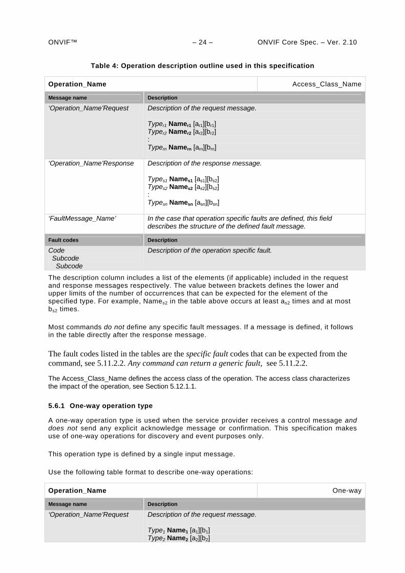
Operations in the specification are defined using the following table format outlined in Table 4.
ONVIF™ – 24 – ONVIF Core Spec. – Ver. 2.10
Table 4: Operation description outline used in this specification
Operation_Name Access_Class_Name
Message name Description
‘Operation_Name’Request Description of the request message. Typer1 Namer1 [ar1][br1] Typer2 Namer2 [ar2][br2] : Typern Namern [arn][brn]
‘Operation_Name’Response Description of the response message. Types1 Names1 [as1][bs2] Types2 Names2 [as2][bs2] : Typesn Namesn [asn][bsn]
‘FaultMessage_Name’ In the case that operation specific faults are defined, this field describes the structure of the defined fault message.
Fault codes Description
Code Subcode Subcode
Description of the operation specific fault.
The description column includes a list of the elements (if applicable) included in the request and response messages respectively. The value between brackets defines the lower and upper limits of the number of occurrences that can be expected for the element of the specified type. For example, Names2 in the table above occurs at least as2 times and at most bs2 times.
Most commands do not define any specific fault messages. If a message is defined, it follows in the table directly after the response message.
The fault codes listed in the tables are the specific fault codes that can be expected from the command, see 5.11.2.2. Any command can return a generic fault, see 5.11.2.2.
The Access_Class_Name defines the access class of the operation. The access class characterizes the impact of the operation, see Section 5.12.1.1.
5.6.1 One-way operation type
A one-way operation type is used when the service provider receives a control message and does not send any explicit acknowledge message or confirmation. This specification makes use of one-way operations for discovery and event purposes only.
This operation type is defined by a single input message.
Use the following table format to describe one-way operations:
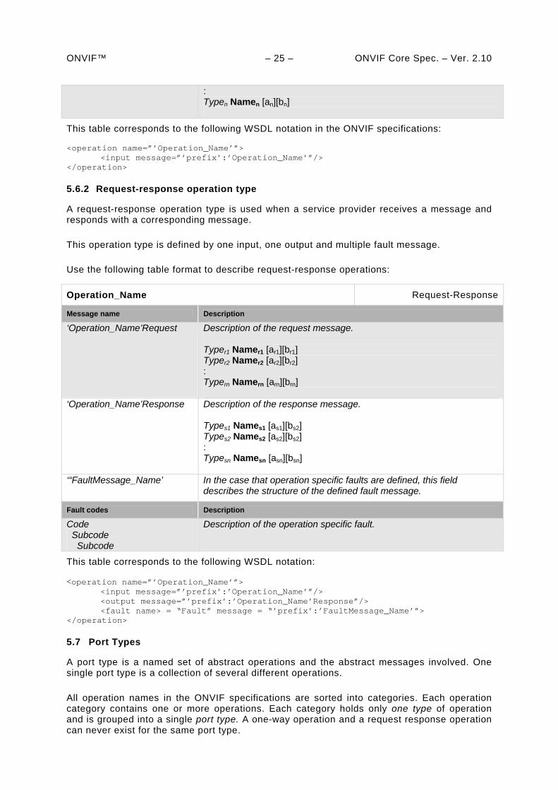
Operation_Name One-way
Message name Description
‘Operation_Name’Request Description of the request message. Type1 Name1 [a1][b1] Type2 Name2 [a2][b2]
ONVIF™ – 25 – ONVIF Core Spec. – Ver. 2.10
: Typen Namen [an][bn]
This table corresponds to the following WSDL notation in the ONVIF specifications:
<operation name=”’Operation_Name’”> <input message=”’prefix’:’Operation_Name’”/> </operation>
5.6.2 Request-response operation type
A request-response operation type is used when a service provider receives a message and responds with a corresponding message.
This operation type is defined by one input, one output and multiple fault message.
Use the following table format to describe request-response operations:
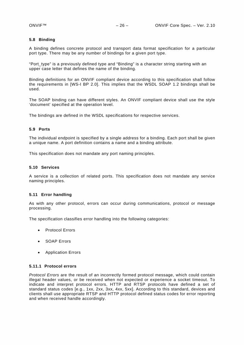
Operation_Name Request-Response
Message name Description
‘Operation_Name’Request Description of the request message. Typer1 Namer1 [ar1][br1] Typer2 Namer2 [ar2][br2] : Typern Namern [arn][brn]
‘Operation_Name’Response Description of the response message. Types1 Names1 [as1][bs2] Types2 Names2 [as2][bs2] : Typesn Namesn [asn][bsn]
‘“FaultMessage_Name’ In the case that operation specific faults are defined, this field describes the structure of the defined fault message.
Fault codes Description
Code Subcode Subcode
Description of the operation specific fault.
This table corresponds to the following WSDL notation:
<operation name=”’Operation_Name’”> <input message=”’prefix’:’Operation_Name’”/>
<output message=”’prefix’:’Operation_Name’Response”/> <fault name> = “Fault” message = “’prefix’:’FaultMessage_Name’”>
</operation>
5.7 Port Types
A port type is a named set of abstract operations and the abstract messages involved. One single port type is a collection of several different operations.
All operation names in the ONVIF specifications are sorted into categories. Each operation category contains one or more operations. Each category holds only one type of operation and is grouped into a single port type. A one-way operation and a request response operation can never exist for the same port type.
ONVIF™ – 26 – ONVIF Core Spec. – Ver. 2.10 5.8 Binding
A binding defines concrete protocol and transport data format specification for a particular port type. There may be any number of bindings for a given port type.
“Port_type” is a previously defined type and “Binding” is a character string starting with an upper case letter that defines the name of the binding.
Binding definitions for an ONVIF compliant device according to this specification shall follow the requirements in [WS-I BP 2.0]. This implies that the WSDL SOAP 1.2 bindings shall be used.
The SOAP binding can have different styles. An ONVIF compliant device shall use the style ‘document’ specified at the operation level.
The bindings are defined in the WSDL specifications for respective services.
5.9 Ports
The individual endpoint is specified by a single address for a binding. Each port shall be given a unique name. A port definition contains a name and a binding attribute.
This specification does not mandate any port naming principles.
5.10 Services
A service is a collection of related ports. This specification does not mandate any service naming principles.
5.11 Error handling
As with any other protocol, errors can occur during communications, protocol or message processing.
The specification classifies error handling into the following categories:
Protocol Errors
SOAP Errors
Application Errors
5.11.1 Protocol errors
Protocol Errors are the result of an incorrectly formed protocol message, which could contain illegal header values, or be received when not expected or experience a socket timeout. To indicate and interpret protocol errors, HTTP and RTSP protocols have defined a set of standard status codes [e.g., 1xx, 2xx, 3xx, 4xx, 5xx]. According to this standard, devices and clients shall use appropriate RTSP and HTTP protocol defined status codes for error reporting and when received handle accordingly.
ONVIF™ – 27 – ONVIF Core Spec. – Ver. 2.10 5.11.2 SOAP errors
SOAP Errors are generated as a result of Web Services operation errors or during SOAP message processing. All such SOAP errors shall be reported and handled through SOAP fault messages. The SOAP specification provides a well defined common framework to handle errors through SOAP fault.
A SOAP fault message is a normal SOAP message with a single well-known element inside the body (soapenv:Fault). To understand the error in more detail, SOAP has defined SOAP fault message structure with various components in it.
Fault code
Subcode
Reason
Node and Role
Fault Details
Subcode and Fault Detail elements information items are intended for carrying application specific error information.
The ONVIF specifications use a separate name space for specific faults (see 5.11.2.2):
ter = “http://www.onvif.org/ver10/error”.
SOAP fault messages for different Web Services are defined as part of the different Web Services definitions. Server and client shall use SOAP 1.2 fault message handling as specified in this specification and shall follow the WS-I Basic Profile 2.0 fault handling recommendations.
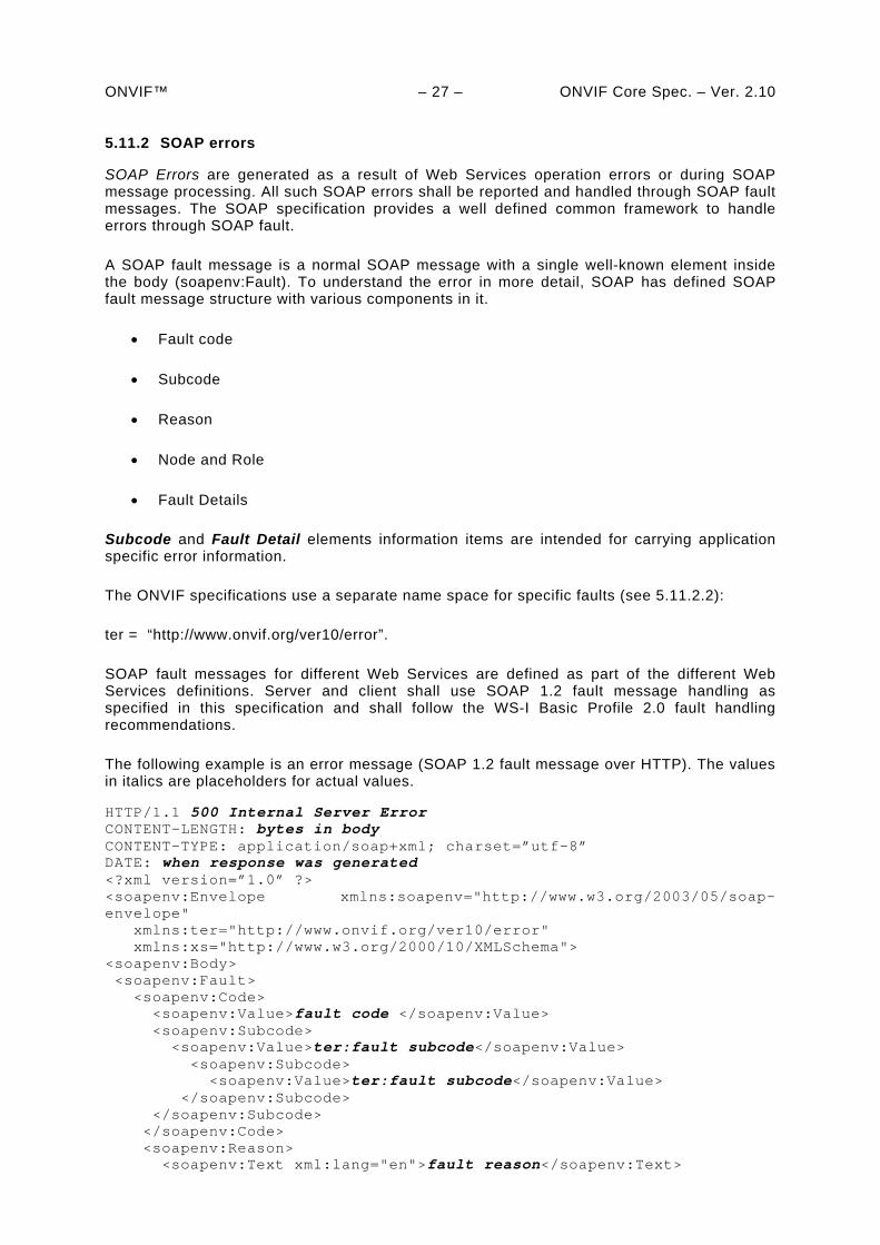
The following example is an error message (SOAP 1.2 fault message over HTTP). The values in italics are placeholders for actual values.
HTTP/1.1 500 Internal Server Error CONTENT-LENGTH: bytes in body CONTENT-TYPE: application/soap+xml; charset=”utf-8” DATE: when response was generated <?xml version=”1.0” ?> <soapenv:Envelope xmlns:soapenv="http://www.w3.org/2003/05/soap-envelope" xmlns:ter="http://www.onvif.org/ver10/error" xmlns:xs="http://www.w3.org/2000/10/XMLSchema"> <soapenv:Body> <soapenv:Fault> <soapenv:Code> <soapenv:Value>fault code </soapenv:Value> <soapenv:Subcode> <soapenv:Value>ter:fault subcode</soapenv:Value> <soapenv:Subcode> <soapenv:Value>ter:fault subcode</soapenv:Value> </soapenv:Subcode> </soapenv:Subcode> </soapenv:Code> <soapenv:Reason> <soapenv:Text xml:lang="en">fault reason</soapenv:Text>
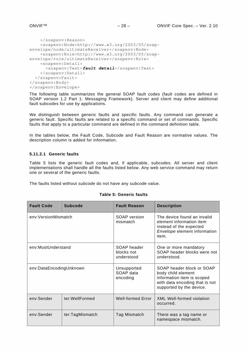
ONVIF™ – 28 – ONVIF Core Spec. – Ver. 2.10 </soapenv:Reason> <soapenv:Node>http://www.w3.org/2003/05/soap-envelope/node/ultimateReceiver</soapenv:Node> <soapenv:Role>http://www.w3.org/2003/05/soap-envelope/role/ultimateReceiver</soapenv:Role> <soapenv:Detail> <soapenv:Text>fault detail</soapenv:Text> </soapenv:Detail> </soapenv:Fault> </soapenv:Body> </soapenv:Envelope>
The following table summarizes the general SOAP fault codes (fault codes are defined in SOAP version 1.2 Part 1: Messaging Framework). Server and client may define additional fault subcodes for use by applications.
We distinguish between generic faults and specific faults. Any command can generate a generic fault. Specific faults are related to a specific command or set of commands. Specific faults that apply to a particular command are defined in the command definition table.
In the tables below, the Fault Code, Subcode and Fault Reason are normative values. The description column is added for information.
5.11.2.1 Generic faults
Table 5 lists the generic fault codes and, if applicable, subcodes. All server and client implementations shall handle all the faults listed below. Any web service command may return one or several of the generic faults.
The faults listed without subcode do not have any subcode value.
Table 5: Generic faults
Fault Code Subcode Fault Reason Description
env:VersionMismatch SOAP version mismatch
The device found an invalid element information item instead of the expected Envelope element information item.
env:MustUnderstand SOAP header blocks not understood
One or more mandatory SOAP header blocks were not understood.
env:DataEncodingUnknown Unsupported SOAP data encoding
SOAP header block or SOAP body child element information item is scoped with data encoding that is not supported by the device.
env:Sender ter:WellFormed Well-formed Error XML Well-formed violation occurred.
env:Sender ter:TagMismatch Tag Mismatch There was a tag name or namespace mismatch.
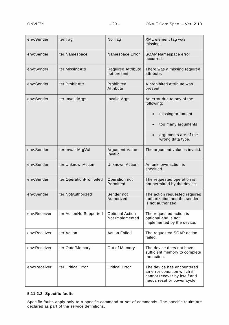
ONVIF™ – 29 – ONVIF Core Spec. – Ver. 2.10
env:Sender ter:Tag No Tag XML element tag was missing.
env:Sender ter:Namespace Namespace Error SOAP Namespace error occurred.
env:Sender ter:MissingAttr Required Attribute not present
There was a missing required attribute.
env:Sender ter:ProhibAttr Prohibited Attribute
A prohibited attribute was present.
env:Sender ter:InvalidArgs Invalid Args An error due to any of the following:
missing argument
too many arguments
arguments are of the wrong data type.
env:Sender ter:InvalidArgVal Argument Value Invalid
The argument value is invalid.
env:Sender ter:UnknownAction Unknown Action An unknown action is specified.
env:Sender ter:OperationProhibited Operation not Permitted
The requested operation is not permitted by the device.
env:Sender ter:NotAuthorized Sender not Authorized
The action requested requires authorization and the sender is not authorized.
env:Receiver ter:ActionNotSupported Optional Action Not Implemented
The requested action is optional and is not implemented by the device.
env:Receiver ter:Action Action Failed The requested SOAP action failed.
env:Receiver ter:OutofMemory Out of Memory The device does not have sufficient memory to complete the action.
env:Receiver ter:CriticalError Critical Error The device has encountered an error condition which it cannot recover by itself and needs reset or power cycle.
5.11.2.2 Specific faults
Specific faults apply only to a specific command or set of commands. The specific faults are declared as part of the service definitions.
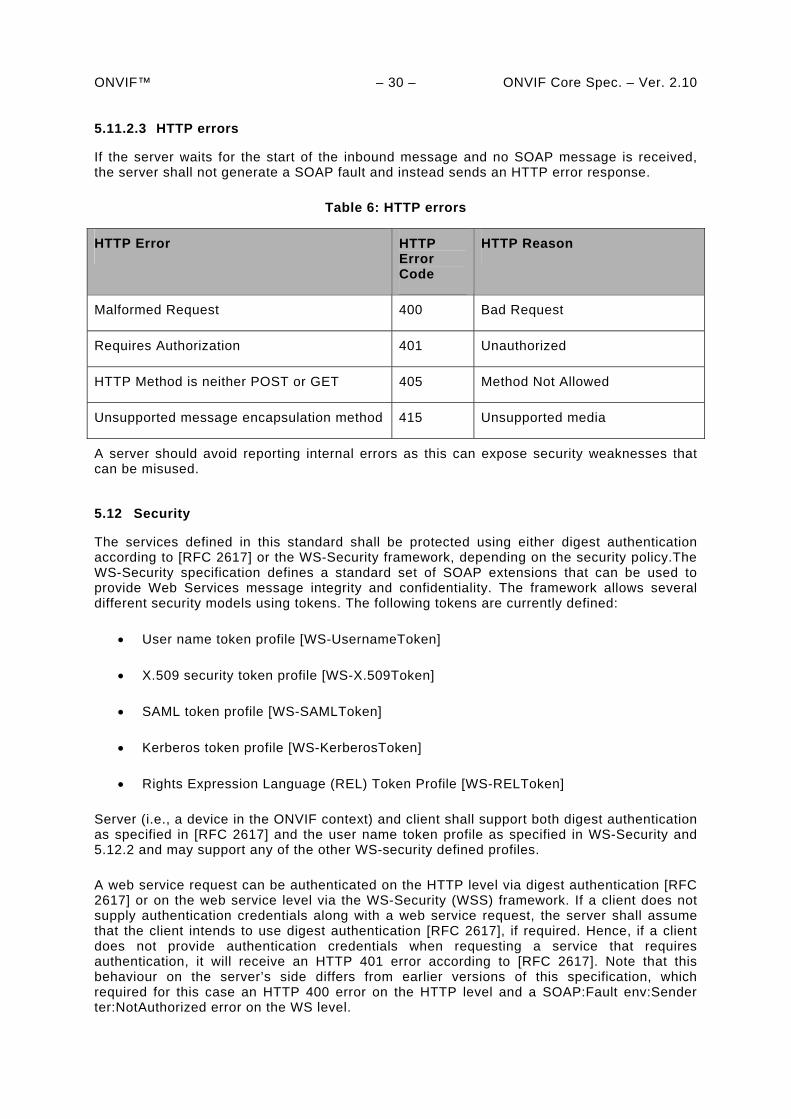
ONVIF™ – 30 – ONVIF Core Spec. – Ver. 2.10 5.11.2.3 HTTP errors
If the server waits for the start of the inbound message and no SOAP message is received, the server shall not generate a SOAP fault and instead sends an HTTP error response.
Table 6: HTTP errors
HTTP Error HTTP Error Code
HTTP Reason
Malformed Request 400 Bad Request
Requires Authorization 401 Unauthorized
HTTP Method is neither POST or GET 405 Method Not Allowed
Unsupported message encapsulation method 415 Unsupported media
A server should avoid reporting internal errors as this can expose security weaknesses that can be misused.
5.12 Security
The services defined in this standard shall be protected using either digest authentication according to [RFC 2617] or the WS-Security framework, depending on the security policy.The WS-Security specification defines a standard set of SOAP extensions that can be used to provide Web Services message integrity and confidentiality. The framework allows several different security models using tokens. The following tokens are currently defined:
User name token profile [WS-UsernameToken]
X.509 security token profile [WS-X.509Token]
SAML token profile [WS-SAMLToken]
Kerberos token profile [WS-KerberosToken]
Rights Expression Language (REL) Token Profile [WS-RELToken]
Server (i.e., a device in the ONVIF context) and client shall support both digest authentication as specified in [RFC 2617] and the user name token profile as specified in WS-Security and 5.12.2 and may support any of the other WS-security defined profiles.
A web service request can be authenticated on the HTTP level via digest authentication [RFC 2617] or on the web service level via the WS-Security (WSS) framework. If a client does not supply authentication credentials along with a web service request, the server shall assume that the client intends to use digest authentication [RFC 2617], if required. Hence, if a client does not provide authentication credentials when requesting a service that requires authentication, it will receive an HTTP 401 error according to [RFC 2617]. Note that this behaviour on the server’s side differs from earlier versions of this specification, which required for this case an HTTP 400 error on the HTTP level and a SOAP:Fault env:Sender ter:NotAuthorized error on the WS level.
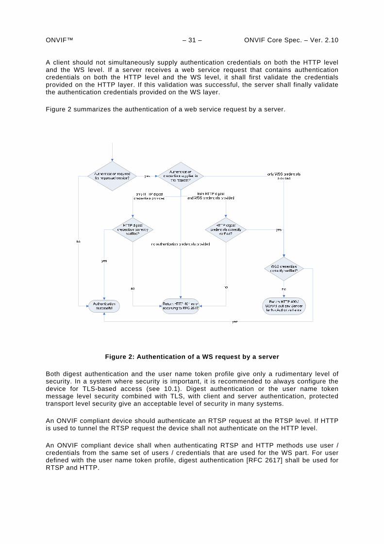
ONVIF™ – 31 – ONVIF Core Spec. – Ver. 2.10 A client should not simultaneously supply authentication credentials on both the HTTP level and the WS level. If a server receives a web service request that contains authentication credentials on both the HTTP level and the WS level, it shall first validate the credentials provided on the HTTP layer. If this validation was successful, the server shall finally validate the authentication credentials provided on the WS layer.
Figure 2 summarizes the authentication of a web service request by a server.
Figure 2: Authentication of a WS request by a server
Both digest authentication and the user name token profile give only a rudimentary level of security. In a system where security is important, it is recommended to always configure the device for TLS-based access (see 10.1). Digest authentication or the user name token message level security combined with TLS, with client and server authentication, protected transport level security give an acceptable level of security in many systems.
An ONVIF compliant device should authenticate an RTSP request at the RTSP level. If HTTP is used to tunnel the RTSP request the device shall not authenticate on the HTTP level.
An ONVIF compliant device shall when authenticating RTSP and HTTP methods use user / credentials from the same set of users / credentials that are used for the WS part. For user defined with the user name token profile, digest authentication [RFC 2617] shall be used for RTSP and HTTP.
ONVIF™ – 32 – ONVIF Core Spec. – Ver. 2.10 5.12.1 User-based access control
The authorization framework described in Sect. 5.12 allows for authentication of service requests. Once a service request is authenticated, the device shall decide based on its access policy whether the requestor is authorized to receive the service.
A device may support the definition of a custom access policy by the device user through the get and set access policy operations defined in Section 8.4.
5.12.1.1 Default Access Policy
By default, the device should enforce the following default access policy, which gives an acceptable level of security in many systems.
Each user is associated exactly one of the following user levels:
1. Administrator
2. Operator
3. Media user
4. Anonymous
Unauthenticated users are placed into the anonymous category and a device shall not allow users to be added to the anonymous user level category.
The services are classified into access classes based to their impact (see Section 5.6). The following access classes are defined:
PRE_AUTH The service shall not require user authentication. Example: GetEndpointReference
READ_SYSTEM The service reads system configuration information from the device. Example: GetNetworkInterfaces
READ_SYSTEM_SECRET The service reads confidential system configuration information from the device. Example: GetSystemLog
WRITE_SYSTEM The service causes changes to the system configuration of the device. Example: SetNetworkDefaultGateway
UNRECOVERABLE The service causes unrecoverable changes to the system configuration of the device. Example: SetSystemFactoryDefault
READ_MEDIA The service reads data related to recorded media. Example: GetRecordings
ACTUATE The service affects the runtime behaviour of the system. Example: CreateRecordingJob
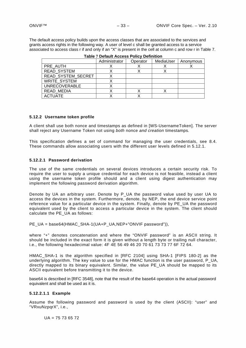
ONVIF™ – 33 – ONVIF Core Spec. – Ver. 2.10 The default access policy builds upon the access classes that are associated to the services and grants access rights in the following way. A user of level c shall be granted access to a service associated to access class r if and only if an "X" is present in the cell at column c and row r in Table 7.
Table 7 Default Access Policy Definition Administrator Operator MediaUser Anonymous PRE_AUTH X X X X READ_SYSTEM X X X READ_SYSTEM_SECRET X WRITE_SYSTEM X UNRECOVERABLE X READ_MEDIA X X X ACTUATE X X
5.12.2 Username token profile
A client shall use both nonce and timestamps as defined in [WS-UsernameToken]. The server shall reject any Username Token not using both nonce and creation timestamps.
This specification defines a set of command for managing the user credentials, see 8.4. These commands allow associating users with the different user levels defined in 5.12.1.
5.12.2.1 Password derivation
The use of the same credentials on several devices introduces a certain security risk. To require the user to supply a unique credential for each device is not feasible, instead a client using the username token profile should and a client using digest authentication may implement the following password derivation algorithm.
Denote by UA an arbitrary user. Denote by P_UA the password value used by user UA to access the devices in the system. Furthermore, denote, by NEP, the end device service point reference value for a particular device in the system. Finally, denote by PE_UA the password equivalent used by the client to access a particular device in the system. The client should calculate the PE_UA as follows:
PE_UA = base64(HMAC_SHA-1(UA+P_UA,NEP+”ONVIF password”)),
where “+” denotes concatenation and where the “ONVIF password” is an ASCII string. It should be included in the exact form it is given without a length byte or trailing null character, i.e., the following hexadecimal value: 4F 4E 56 49 46 20 70 61 73 73 77 6F 72 64.
HMAC_SHA-1 is the algorithm specified in [RFC 2104] using SHA-1 [FIPS 180-2] as the underlying algorithm. The key value to use for the HMAC function is the user password, P_UA, directly mapped to its binary equivalent. Similar, the value PE_UA should be mapped to its ASCII equivalent before transmitting it to the device.
base64 is described in [RFC 3548], note that the result of the base64 operation is the actual password equivalent and shall be used as it is.
5.12.2.1.1 Example
Assume the following password and password is used by the client (ASCII): “user” and “VRxuNzpqrX”, i.e.,
UA = 75 73 65 72
ONVIF™ – 34 – ONVIF Core Spec. – Ver. 2.10
P_UA = 56 52 78 75 4E 7A 70 71 72 58
Next, assume the device has the following device service end point reference value:
Urn:uuid:f81d4fae-7dec-11d0-a765-00a0c91e6bf6.
Then the password equivalent to be used will be then calculated as:
PE_UA = base64(HMAC_SHA-1(UA+ P_UA,NEP+”ONVIF password”)) =
base64(HMAC_SHA-1(75736572565278754E7A70717258,
F81D4fAE7DEC11D0A76500A0C91E6BF6+4F4E5649462070617373776F7264)) =
base64(16 E5 C5 A9 4D DE 8A 97 6D D7 2F 55 78 5F C2 D0 6B DA 53 4A)=
FuXFqU3eipdt1y9VeF/C0GvaU0o=
The resulting password equivalence “FuXFqU3eipdt1y9VeF/C0GvaU0o=” is the password that shall be used by a client both for configuring the user credential on the particular device and then also for accessing the device.
ONVIF™ – 35 – ONVIF Core Spec. – Ver. 2.10
6 IP configuration
The device and client communicate over an open or closed IP network. This standard does not place any general restrictions or requirements on the network type. It shall be possible, however, to establish communication links between the entities according to the architectural framework specified in 4. Device IP configuration includes parameters such as IP addresses and a default gateway.
An ONVIF compliant device shall have at least one network interface that gives it IP network connectivity. Similarly, the client shall have at least one network interface that gives IP connectivity and allows data communication between the device and the client.
Both device and client shall support IPv4 based network communication. The device and client should support IPv6 based network communication.
It shall be possible to make static IP configuration on the device using a network or local configuration interface.
An ONVIF compliant device should support dynamic IP configuration of link-local addresses according to [RFC3927]. A device that supports IPv6 shall support stateless IP configuration according to [RFC4862] and neighbour discovery according to RFC4861.
The device shall support dynamic IP configuration according to [RFC 2131]. A device that supports IPv6 shall support stateful IP configuration according to [RFC3315].
The device may support any additional IP configuration mechanism.
Network configuration of a device shall be provided via the ONVIF device management service as specified in section 8.2 and may additionally be provided through local interfaces. The latter is outside the scope of this specification.
The default device configuration shall have both DHCP and dynamic link-local (stateless) address configuration enabled. Even if the device is configured through a static address configuration it should have the link-local address default enabled.
When a device is connected to an IPv4 network, address assignment priorities (link local versus routable address) should be done as recommended in [RFC3927].
Further details regarding how the IP connectivity is achieved are outside the scope of this standard.
ONVIF™ – 36 – ONVIF Core Spec. – Ver. 2.10
7 Device discovery
7.1 General
A client searches for available devices using the dynamic Web Services discovery protocol [WS-Discovery].
A device compliant with this specification shall implement the Target Service role as specified in [WS-Discovery].
A client compliant with this specification shall implement the Client role as specified in [WS-Discovery].
The Discovery Proxy role as described in [WS-Discovery] shall not be supported by a device or a client (an alternative Discovery Proxy role is introduced in this specification, see Section 7.4). A device that implements the client role ignores the interaction scheme with the Discovery Proxy as described in Section 3 in [WS-Discovery]. Instead, this specification defines a new Discovery Proxy role that allows remote discovery. The remote discovery relies on the presence of a Discovery Proxy and a system provider that would like to offer remote discovery in the system should implement the Discovery Proxy role as specified in Section 7.4
[WS-Discovery] describes the Universally Unique Identifier (UUID): URI format recommendation for endpoint references in Section 2.6, but this specification overrides this recommendation. Instead, the Uniform Resource Name: Universally Unique Identifier (URN:UUID) format is used [RFC4122] (see Section 7.3.1).
7.2 Modes of operation
The device shall be able to operate in two modes:
Discoverable
Non-discoverable
A device in discoverable mode sends multicast Hello messages once connected to the network or sends its Status changes according to [WS-Discovery]. In addition it always listens for Probe and Resolve messages and sends responses accordingly. A device in non-discoverable shall not listen to [WS-Discovery] messages or send such messages.
The devices default behaviour shall be the discoverable mode. In order to thwart denial-of-service attacks, it shall be possible to set a device into non-discoverable mode through the operation defined in 8.3.19.
7.3 Discovery definitions
7.3.1 Endpoint reference
A device or an endpoint that takes the client role should use a URN:UUID [RFC4122] as the address property of its endpoint reference.
The device or an endpoint that takes the client role shall use a stable, globally unique identifier that is constant across network interfaces as part of its endpoint reference property. The combination of an wsadis:Address and wsadis:ReferenceProperties provide a stable and globally-unique identifier.
ONVIF™ – 37 – ONVIF Core Spec. – Ver. 2.10 7.3.2 Hello
7.3.2.1 Types
An ONVIF compliant device shall include the device management service port type, i.e. tds:Device, in the <d:Types> declaration.
The following example shows how the type is encoded in the SOAP Hello body:
<d:Types>tds:Device</d:Types>.
The Hello message may include additional types.
7.3.2.2 Scopes
An ONVIF compliant device shall include the scope <d:Scopes> attribute with the scopes of the device in the Hello message.
The device scope is set by using [RFC 3986] URIs. This specification defines scope attributes as follows:
The scheme attribute:onvif
The authority attribute:www.onvif.org
This implies that all ONVIF defined scope URIs have the following format:
onvif://www.onvif.org/<path>
A device may have other scope URIs. These URIs are not restricted of ONVIF defined scopes.
Table 8 defines a set of scope parameters. Apart from these standardized parameters, it shall be possible to set any scope parameter as defined by the device owner. Scope parameters can be listed and set through the commands defined in Section 8.3. For each device type the type specification defines its primary type.These are outside of the scope of this specification.
A device may have other scope URIs. These URIs are not restricted of ONVIF defined scopes.
ONVIF™ – 38 – ONVIF Core Spec. – Ver. 2.10
Table 8: Scope parameters
Category Defined values Description
type Any character string. Value that indicates the type of the device. The defined values are outside of the scope of this document and are defined in the device type definition documents.
location Any character string or path value.
The location defines the physical location of the device. The location value might be any string describing the physical location of the device. A device shall include at least one location entry into its scope list.
hardware Any character string or path value.
A string or path value describing the hardware of the device. A device shall include at least one hardware entry into its scope list.
name Any character string or path value.
The searchable name of the device. A device shall include at least one name entry into its scope list.
A device shall include at least one entry of the type, location, hardware and name categories respectively in the scopes list. A device may include any other additional scope attributes in the scopes list.
A device might include an arbitrary number of scopes in its scope list. This implies that one unit might for example define several different location scopes. A probe is matched against all scopes in the list.
7.3.2.2.1 Example
The following example illustrates the usage of the scope value. This is just an example, and not at all an indication of what type of scope parameter to be part of an NVT configuration. In this example we assume that the NVT is configured with the following scopes: onvif://www.onvif.org/type/Network_Video_Transmitter onvif://www.onvif.org/type/video_encoder onvif://www.onvif.org/type/ptz onvif://www.onvif.org/type/audio_encoder onvif://www.onvif.org/type/video_analytics onvif://www.onvif.org/hardware/D1-566 onvif://www.onvif.org/location/country/china onvif://www.onvif.org/location/city/bejing onvif://www.onvif.org/location/building/headquarter onvif://www.onvif.org/location/floor/R5 onvif://www.onvif.org/name/ARV-453
A client that probes for the device with scope onvif://www.onvif.org will get a match. Similarly, a probe for the device with scope:
onvif://www.onvif.org/location/country/china
will give a match. A probe with:
onvif://www.onvif.org/hardware/D1
will not give a match.
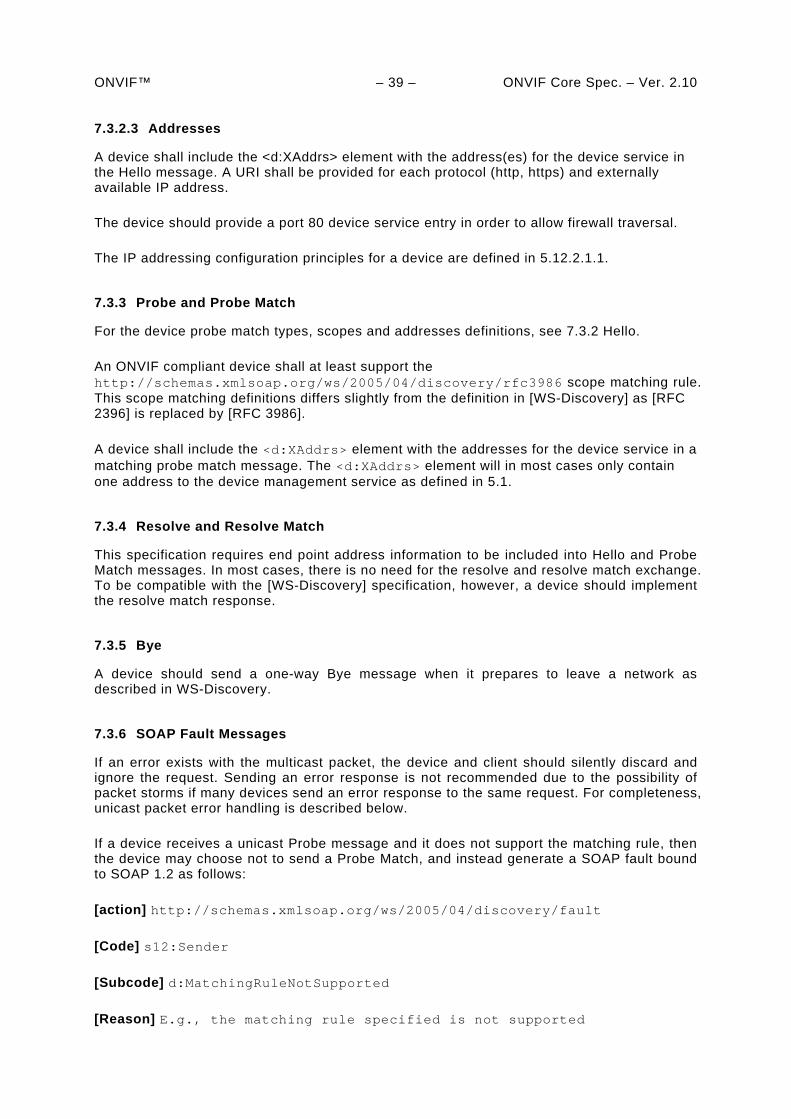
ONVIF™ – 39 – ONVIF Core Spec. – Ver. 2.10 7.3.2.3 Addresses
A device shall include the <d:XAddrs> element with the address(es) for the device service in the Hello message. A URI shall be provided for each protocol (http, https) and externally available IP address.
The device should provide a port 80 device service entry in order to allow firewall traversal.
The IP addressing configuration principles for a device are defined in 5.12.2.1.1.
7.3.3 Probe and Probe Match
For the device probe match types, scopes and addresses definitions, see 7.3.2 Hello.
An ONVIF compliant device shall at least support the http://schemas.xmlsoap.org/ws/2005/04/discovery/rfc3986 scope matching rule. This scope matching definitions differs slightly from the definition in [WS-Discovery] as [RFC 2396] is replaced by [RFC 3986].
A device shall include the <d:XAddrs> element with the addresses for the device service in a matching probe match message. The <d:XAddrs> element will in most cases only contain one address to the device management service as defined in 5.1.
7.3.4 Resolve and Resolve Match
This specification requires end point address information to be included into Hello and Probe Match messages. In most cases, there is no need for the resolve and resolve match exchange. To be compatible with the [WS-Discovery] specification, however, a device should implement the resolve match response.
7.3.5 Bye
A device should send a one-way Bye message when it prepares to leave a network as described in WS-Discovery.
7.3.6 SOAP Fault Messages
If an error exists with the multicast packet, the device and client should silently discard and ignore the request. Sending an error response is not recommended due to the possibility of packet storms if many devices send an error response to the same request. For completeness, unicast packet error handling is described below.
If a device receives a unicast Probe message and it does not support the matching rule, then the device may choose not to send a Probe Match, and instead generate a SOAP fault bound to SOAP 1.2 as follows:
[action] http://schemas.xmlsoap.org/ws/2005/04/discovery/fault
[Code] s12:Sender
[Subcode] d:MatchingRuleNotSupported
[Reason] E.g., the matching rule specified is not supported
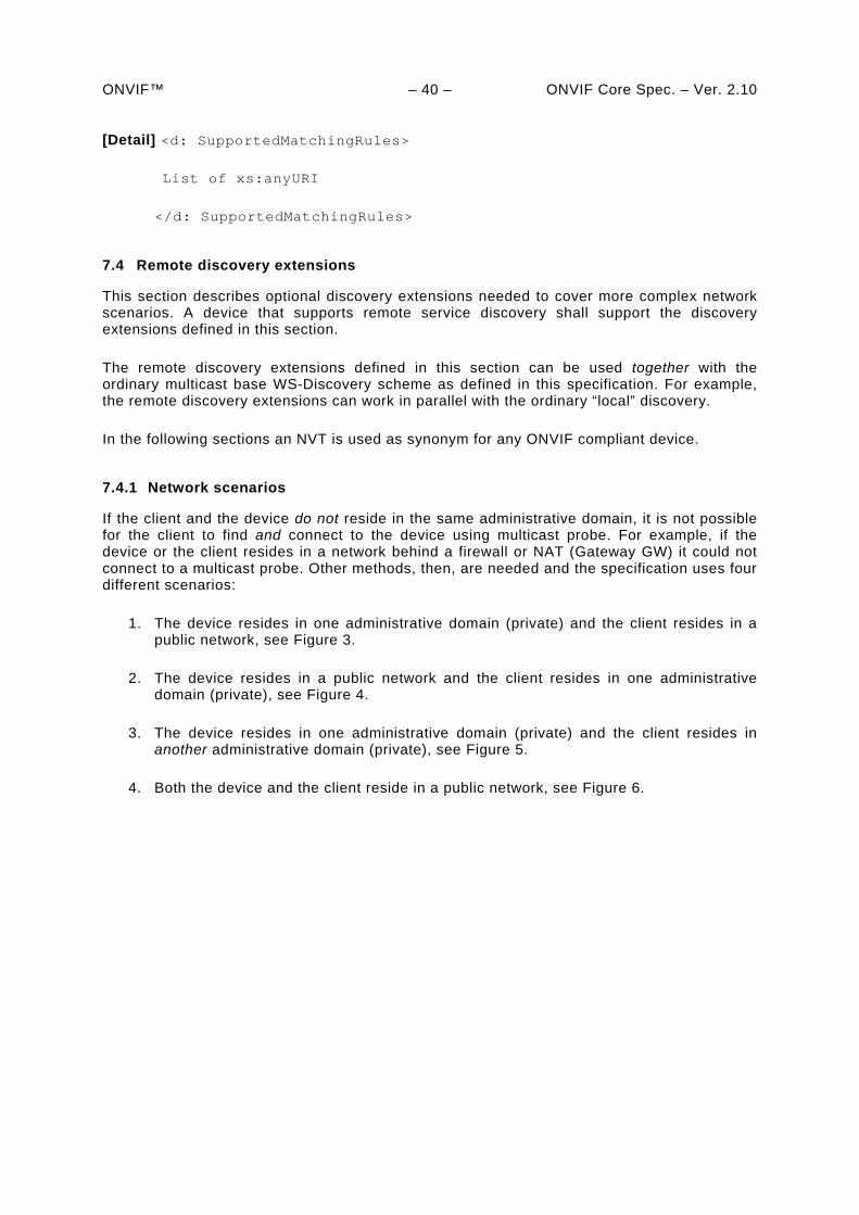
ONVIF™ – 40 – ONVIF Core Spec. – Ver. 2.10 [Detail] <d: SupportedMatchingRules>
List of xs:anyURI
</d: SupportedMatchingRules>
7.4 Remote discovery extensions
This section describes optional discovery extensions needed to cover more complex network scenarios. A device that supports remote service discovery shall support the discovery extensions defined in this section.
The remote discovery extensions defined in this section can be used together with the ordinary multicast base WS-Discovery scheme as defined in this specification. For example, the remote discovery extensions can work in parallel with the ordinary “local” discovery.
In the following sections an NVT is used as synonym for any ONVIF compliant device.
7.4.1 Network scenarios
If the client and the device do not reside in the same administrative domain, it is not possible for the client to find and connect to the device using multicast probe. For example, if the device or the client resides in a network behind a firewall or NAT (Gateway GW) it could not connect to a multicast probe. Other methods, then, are needed and the specification uses four different scenarios:
1. The device resides in one administrative domain (private) and the client resides in a public network, see Figure 3.
2. The device resides in a public network and the client resides in one administrative domain (private), see Figure 4.
3. The device resides in one administrative domain (private) and the client resides in another administrative domain (private), see Figure 5.
4. Both the device and the client reside in a public network, see Figure 6.
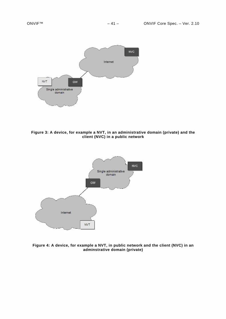
ONVIF™ – 41 – ONVIF Core Spec. – Ver. 2.10
Figure 3: A device, for example a NVT, in an administrative domain (private) and the client (NVC) in a public network
Figure 4: A device, for example a NVT, in public network and the client (NVC) in an
adminstrative domain (private)
ONVIF™ – 42 – ONVIF Core Spec. – Ver. 2.10
Figure 5: A device, for example a NVT, in an administrative domain (private) and the
client (NVC) in another administrative domain (private)
Figure 6: Both a device, for example a NVT, and the client (NVC) in a public network.
The [WS-Discovery] specification introduces a Discovery Proxy (DP) to solve some of these scenarios. However the [WS-Discovery] specification does not have support for all the network scenarios introduced in this specification. This specification defines a DP that enables “plug and play” also for the more complex network scenarios we have listed above. This DP is not compliant with [WS-Discovery] specification.
7.4.2 Discover proxy
A network administrator configuring a network for a device in a wide area network spanning several administrative domains, needs to introduce a DP endpoint into the system. The DP performs the following tasks:
1. Listen for device hello messages and responds to these as defined in Section 7.4.3.
2. Responds to probe queries on behalf of registered devices from clients.
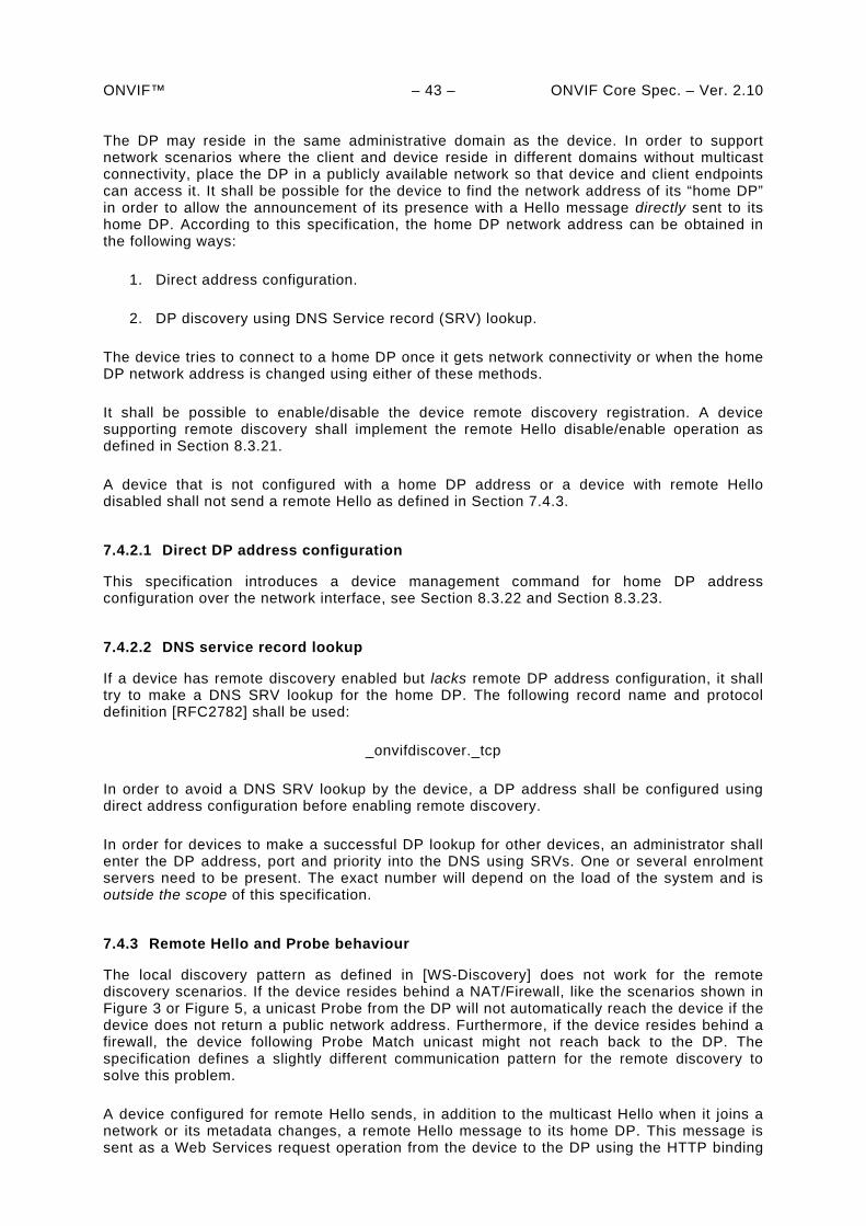
ONVIF™ – 43 – ONVIF Core Spec. – Ver. 2.10 The DP may reside in the same administrative domain as the device. In order to support network scenarios where the client and device reside in different domains without multicast connectivity, place the DP in a publicly available network so that device and client endpoints can access it. It shall be possible for the device to find the network address of its “home DP” in order to allow the announcement of its presence with a Hello message directly sent to its home DP. According to this specification, the home DP network address can be obtained in the following ways:
1. Direct address configuration.
2. DP discovery using DNS Service record (SRV) lookup.
The device tries to connect to a home DP once it gets network connectivity or when the home DP network address is changed using either of these methods.
It shall be possible to enable/disable the device remote discovery registration. A device supporting remote discovery shall implement the remote Hello disable/enable operation as defined in Section 8.3.21.
A device that is not configured with a home DP address or a device with remote Hello disabled shall not send a remote Hello as defined in Section 7.4.3.
7.4.2.1 Direct DP address configuration
This specification introduces a device management command for home DP address configuration over the network interface, see Section 8.3.22 and Section 8.3.23.
7.4.2.2 DNS service record lookup
If a device has remote discovery enabled but lacks remote DP address configuration, it shall try to make a DNS SRV lookup for the home DP. The following record name and protocol definition [RFC2782] shall be used:
_onvifdiscover._tcp
In order to avoid a DNS SRV lookup by the device, a DP address shall be configured using direct address configuration before enabling remote discovery.
In order for devices to make a successful DP lookup for other devices, an administrator shall enter the DP address, port and priority into the DNS using SRVs. One or several enrolment servers need to be present. The exact number will depend on the load of the system and is outside the scope of this specification.
7.4.3 Remote Hello and Probe behaviour
The local discovery pattern as defined in [WS-Discovery] does not work for the remote discovery scenarios. If the device resides behind a NAT/Firewall, like the scenarios shown in Figure 3 or Figure 5, a unicast Probe from the DP will not automatically reach the device if the device does not return a public network address. Furthermore, if the device resides behind a firewall, the device following Probe Match unicast might not reach back to the DP. The specification defines a slightly different communication pattern for the remote discovery to solve this problem.
A device configured for remote Hello sends, in addition to the multicast Hello when it joins a network or its metadata changes, a remote Hello message to its home DP. This message is sent as a Web Services request operation from the device to the DP using the HTTP binding
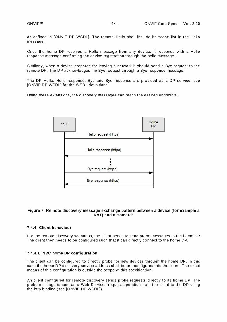
ONVIF™ – 44 – ONVIF Core Spec. – Ver. 2.10 as defined in [ONVIF DP WSDL]. The remote Hello shall include its scope list in the Hello message.
Once the home DP receives a Hello message from any device, it responds with a Hello response message confirming the device registration through the hello message.
Similarly, when a device prepares for leaving a network it should send a Bye request to the remote DP. The DP acknowledges the Bye request through a Bye response message.
The DP Hello, Hello response, Bye and Bye response are provided as a DP service, see [ONVIF DP WSDL] for the WSDL definitions.
Using these extensions, the discovery messages can reach the desired endpoints.
Figure 7: Remote discovery message exchange pattern between a device (for example a NVT) and a HomeDP
7.4.4 Client behaviour
For the remote discovery scenarios, the client needs to send probe messages to the home DP. The client then needs to be configured such that it can directly connect to the home DP.
7.4.4.1 NVC home DP configuration
The client can be configured to directly probe for new devices through the home DP. In this case the home DP discovery service address shall be pre-configured into the client. The exact means of this configuration is outside the scope of this specification.
An client configured for remote discovery sends probe requests directly to its home DP. The probe message is sent as a Web Services request operation from the client to the DP using the http binding (see [ONVIF DP WSDL]).
ONVIF™ – 45 – ONVIF Core Spec. – Ver. 2.10 Once the home DP receives a Probe message from any client, it responses with corresponding Probe Match message according to the normal WS-Discovery message exchange pattern, see the sequence chart in Figure 8.
Figure 8: Message sequence for clients (NVC) pre-configured with home DP address
7.4.5 Security
7.4.5.1 Local discovery
Security and discovery can be viewed as contradictory goals. While the main idea behind a discovery protocol is to announce the presence of a service, it is hard to exclude other endpoints from access to the service announcements. WS-Discovery does not provide any extra access to services (if the other security mechanism specified in this specification are used), even on the same LAN; it merely announces their existence. Furthermore, local discovery works only within multicast reach range. Thus, the main security impact of WS-Discovery is the risk of denial of service attacks on devices or privacy issues if it is important to hide the presence of devices in the network. The risk of the latter two problems will very much depend on the device deployment environment. In order to reduce these threats, this specification has introduced the two different discovery modes, see Section 7.2. This always gives the possibility for the client to switch off the device discovery function in the device. In non-discoverable mode, a device will never announce its presence with Hello messages or respond to any Probe or Resolve requests.
7.4.5.2 Remote discovery
In the remote network scenario, the DP resides on the Internet and is vulnerable. Extra security measurements, then, shall be taken to protect the DP from attacks. The remote Hello and Probe and Probe Match messages, as defined in Section 7.4.3, shall be sent over HTTPS. This transport will not prevent denial of service attacks, but it can protect it from illegal device registrations if client authentication is used. If protection of denial of service is a major concern, other measurements need to be taken, which is outside the scope of the current specification.

ONVIF™ – 46 – ONVIF Core Spec. – Ver. 2.10 Before registering a device in the device data base the DP should authenticate the device to make sure that it is a “legal” device that announces its presence, for example by using client certificates. Client certificate provisioning is outside the scope of the current specification.
The client to DP remote Probe and Probe Match messages shall be sent over HTTPS. The DP shall authenticate the NVC before responding to a Probe request. This can be done using TLS client certificates or any other suitable client authentication mechanism.
ONVIF™ – 47 – ONVIF Core Spec. – Ver. 2.10
8 Device management
The Device Service is divided into five different categories: capabilities, network, system, I/O and security commands. This set of commands can be used to get information about the device capabilities and configurations or to set device configurations. An ONVIF compliant device shall support the device management service as specified in [ONVIF DM WSDL]. A basic set of operations are required for the device management service, other operations are recommended or optional to support. The detailed requirements are listed under the command descriptions.
8.1 Capabilities
8.1.1 Get WSDL URL
It is possible for an endpoint to request a URL that can be used to retrieve the complete schema and WSDL definitions of a device. The command gives in return a URL entry point where all the necessary product specific WSDL and schema definitions can be retrieved. The device shall provide a URL for WSDL and schema download through the GetWsdlUrl command.
Table 9: Get WSDL URL command
GetWsdlUrl Access Class: PRE_AUTH
Message name Description
GetWsdlUrlRequest This is an empty message.
GetWsdlUrlResponse The requested URL. xs:anyURI WsdlUrl [1][1]
Fault codes Description
No command specific faults!
8.1.2 Capability exchange
Any endpoint can ask for the capabilities of a device using the capability exchange request response operation. The device shall indicate all its ONVIF compliant capabilities through the GetCapabilities command.
The capability list includes references to the addresses (XAddr) of the service implementing the interface operations in the category.
8.1.2.1 GetServices
Returns a collection of the devices services and their available capabilities. The returned capability response message is untyped to allow future addition of services, service revisions and service capabilities.
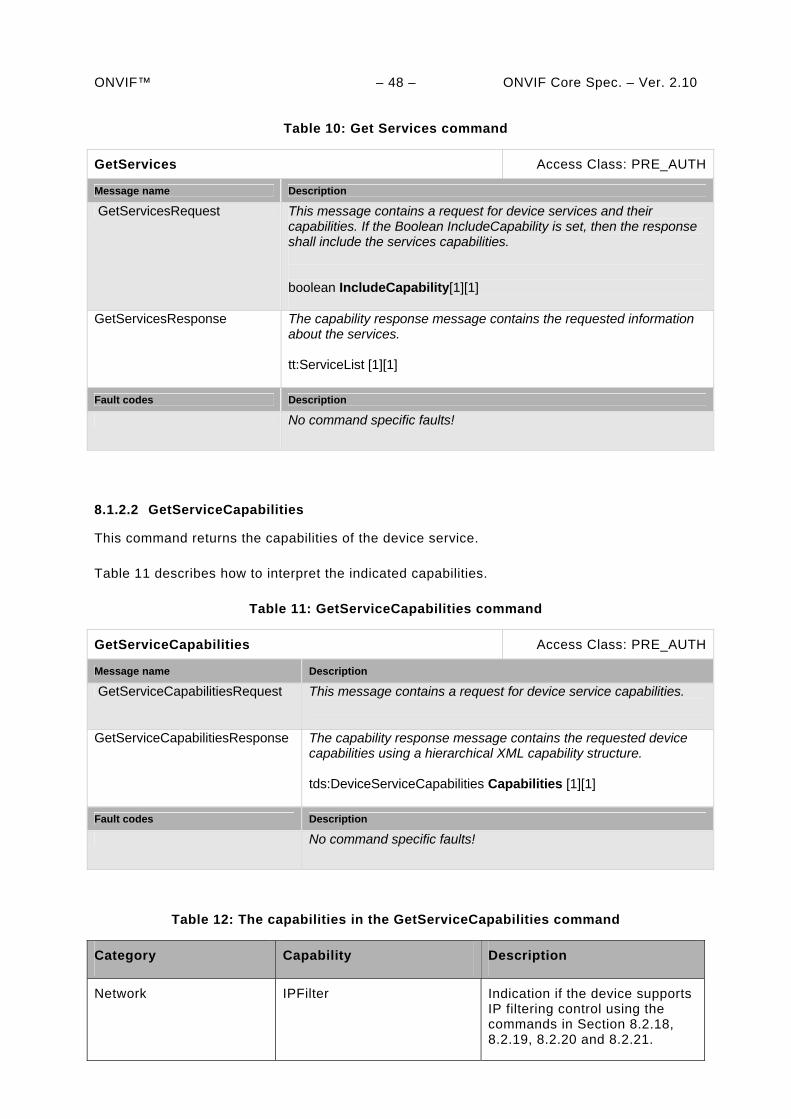
ONVIF™ – 48 – ONVIF Core Spec. – Ver. 2.10
Table 10: Get Services command
GetServices Access Class: PRE_AUTH
Message name Description
GetServicesRequest This message contains a request for device services and their capabilities. If the Boolean IncludeCapability is set, then the response shall include the services capabilities. boolean IncludeCapability[1][1]
GetServicesResponse The capability response message contains the requested information about the services. tt:ServiceList [1][1]
Fault codes Description
No command specific faults!
8.1.2.2 GetServiceCapabilities
This command returns the capabilities of the device service.
Table 11 describes how to interpret the indicated capabilities.
Table 11: GetServiceCapabilities command
GetServiceCapabilities Access Class: PRE_AUTH
Message name Description
GetServiceCapabilitiesRequest This message contains a request for device service capabilities.
GetServiceCapabilitiesResponse The capability response message contains the requested device capabilities using a hierarchical XML capability structure. tds:DeviceServiceCapabilities Capabilities [1][1]
Fault codes Description
No command specific faults!
Table 12: The capabilities in the GetServiceCapabilities command
Category Capability Description
Network IPFilter Indication if the device supports IP filtering control using the commands in Section 8.2.18, 8.2.19, 8.2.20 and 8.2.21.
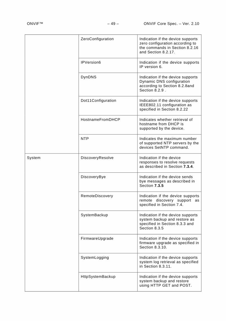
ONVIF™ – 49 – ONVIF Core Spec. – Ver. 2.10
ZeroConfiguration Indication if the device supports zero configuration according to the commands in Section 8.2.16 and Section 8.2.17.
IPVersion6 Indication if the device supports IP version 6.
DynDNS Indication if the device supports Dynamic DNS configuration according to Section 8.2.8and Section 8.2.9 .
Dot11Configuration Indication if the device supports IEEE802.11 configuration as specified in Section 8.2.22
HostnameFromDHCP Indicates whether retrieval of hostname from DHCP is supported by the device.
NTP Indicates the maximum number of supported NTP servers by the devices SetNTP command.
DiscoveryResolve Indication if the device responses to resolve requests as described in Section 7.3.4.
DiscoveryBye Indication if the device sends bye messages as described in Section 7.3.5
RemoteDiscovery Indication if the device supports remote discovery support as specified in Section 7.4.
SystemBackup Indication if the device supports system backup and restore as specified in Section 8.3.3 and Section 8.3.5
FirmwareUpgrade Indication if the device supports firmware upgrade as specified in Section 8.3.10.
SystemLogging Indication if the device supports system log retrieval as specified in Section 8.3.11.
System
HttpSystemBackup Indication if the device supports system backup and restore using HTTP GET and POST.
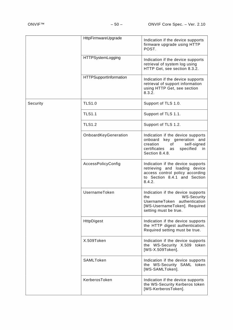
ONVIF™ – 50 – ONVIF Core Spec. – Ver. 2.10
HttpFirmwareUpgrade
Indication if the device supports firmware upgrade using HTTP POST.
HTTPSystemLogging Indication if the device supports retrieval of system log using HTTP Get, see section 8.3.2.
HTTPSupportInformation Indication if the device supports retrieval of support information using HTTP Get, see section 8.3.2.
TLS1.0 Support of TLS 1.0.
TLS1.1 Support of TLS 1.1.
TLS1.2 Support of TLS 1.2.
OnboardKeyGeneration Indication if the device supports onboard key generation and creation of self-signed certificates as specified in Section 8.4.8.
AccessPolicyConfig Indication if the device supports retrieving and loading device access control policy according to Section 8.4.1 and Section 8.4.2.
UsernameToken Indication if the device supports the WS-Security UsernameToken authentication [WS-UsernameToken]. Required setting must be true.
HttpDigest Indication if the device supports the HTTP digest authentication. Required setting must be true.
X.509Token Indication if the device supports the WS-Security X.509 token [WS-X.509Token].
SAMLToken Indication if the device supports the WS-Security SAML token [WS-SAMLToken].
Security
KerberosToken Indication if the device supports the WS-Security Kerberos token [WS-KerberosToken].
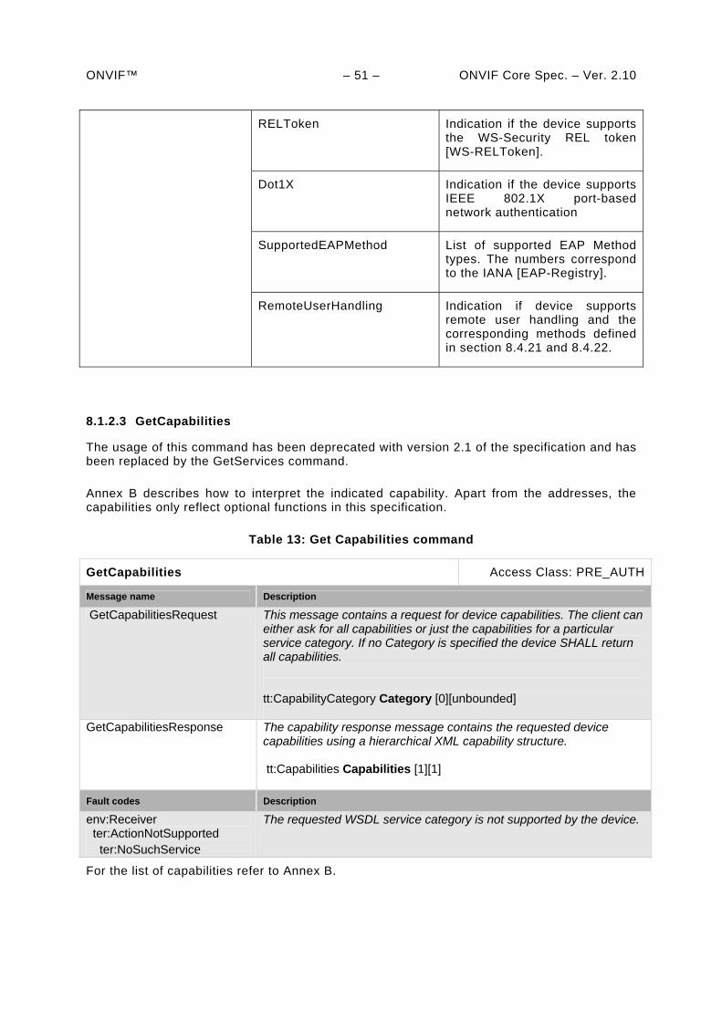
ONVIF™ – 51 – ONVIF Core Spec. – Ver. 2.10
RELToken Indication if the device supports the WS-Security REL token [WS-RELToken].
Dot1X Indication if the device supports IEEE 802.1X port-based network authentication
SupportedEAPMethod List of supported EAP Method types. The numbers correspond to the IANA [EAP-Registry].
RemoteUserHandling Indication if device supports remote user handling and the corresponding methods defined in section 8.4.21 and 8.4.22.
8.1.2.3 GetCapabilities
The usage of this command has been deprecated with version 2.1 of the specification and has been replaced by the GetServices command.
Annex B describes how to interpret the indicated capability. Apart from the addresses, the capabilities only reflect optional functions in this specification.
Table 13: Get Capabilities command
GetCapabilities Access Class: PRE_AUTH
Message name Description
GetCapabilitiesRequest This message contains a request for device capabilities. The client can either ask for all capabilities or just the capabilities for a particular service category. If no Category is specified the device SHALL return all capabilities. tt:CapabilityCategory Category [0][unbounded]
GetCapabilitiesResponse The capability response message contains the requested device capabilities using a hierarchical XML capability structure. tt:Capabilities Capabilities [1][1]
Fault codes Description
env:Receiver ter:ActionNotSupported ter:NoSuchService
The requested WSDL service category is not supported by the device.
For the list of capabilities refer to Annex B.
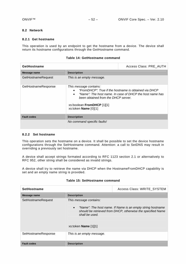
ONVIF™ – 52 – ONVIF Core Spec. – Ver. 2.10 8.2 Network
8.2.1 Get hostname
This operation is used by an endpoint to get the hostname from a device. The device shall return its hostname configurations through the GetHostname command.
Table 14: GetHostname command
GetHostname Access Class: PRE_AUTH
Message name Description
GetHostnameRequest This is an empty message.
GetHostnameResponse This message contains: “FromDHCP”: True if the hostname is obtained via DHCP “Name”: The host name. In case of DHCP the host name has
been obtained from the DHCP server. xs:boolean FromDHCP [1][1] xs:token Name [0][1]
Fault codes Description
No command specific faults!
8.2.2 Set hostname
This operation sets the hostname on a device. It shall be possible to set the device hostname configurations through the SetHostname command. Attention: a call to SetDNS may result in overriding a previously set hostname.
A device shall accept strings formated according to RFC 1123 section 2.1 or alternatively to RFC 952, other string shall be considered as invalid strings.
A device shall try to retrieve the name via DHCP when the HostnameFromDHCP capability is set and an empty name string is provided.
Table 15: SetHostname command
SetHostname Access Class: WRITE_SYSTEM
Message name Description
SetHostnameRequest This message contains:
“Name”: The host name. If Name is an empty string hostname should be retrieved from DHCP, otherwise the specified Name shall be used.
xs:token Name [1][1]
SetHostnameResponse This is an empty message.
Fault codes Description
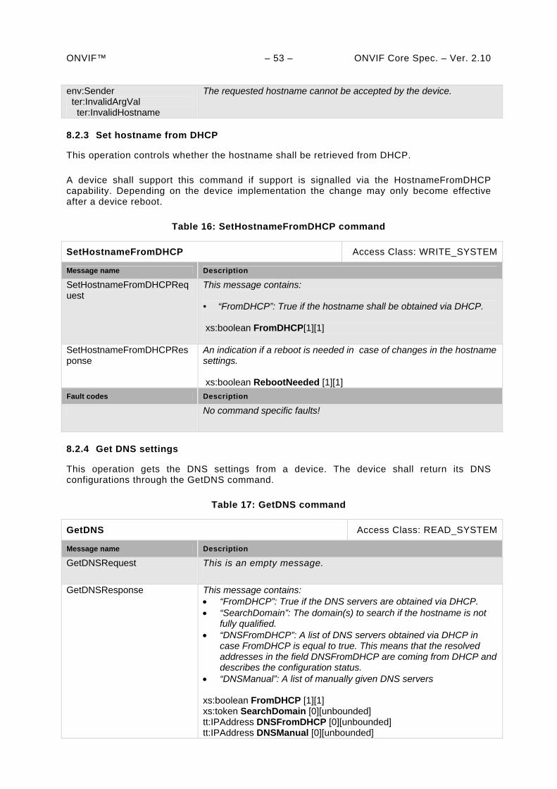
ONVIF™ – 53 – ONVIF Core Spec. – Ver. 2.10 env:Sender ter:InvalidArgVal ter:InvalidHostname
The requested hostname cannot be accepted by the device.
8.2.3 Set hostname from DHCP
This operation controls whether the hostname shall be retrieved from DHCP.
A device shall support this command if support is signalled via the HostnameFromDHCP capability. Depending on the device implementation the change may only become effective after a device reboot.
Table 16: SetHostnameFromDHCP command
SetHostnameFromDHCP Access Class: WRITE_SYSTEM
Message name Description
SetHostnameFromDHCPRequest
This message contains: • “FromDHCP”: True if the hostname shall be obtained via DHCP. xs:boolean FromDHCP[1][1]
SetHostnameFromDHCPResponse
An indication if a reboot is needed in case of changes in the hostname settings. xs:boolean RebootNeeded [1][1]
Fault codes Description
No command specific faults!
8.2.4 Get DNS settings
This operation gets the DNS settings from a device. The device shall return its DNS configurations through the GetDNS command.
Table 17: GetDNS command
GetDNS Access Class: READ_SYSTEM
Message name Description
GetDNSRequest This is an empty message.
GetDNSResponse This message contains: “FromDHCP”: True if the DNS servers are obtained via DHCP. “SearchDomain”: The domain(s) to search if the hostname is not
fully qualified. “DNSFromDHCP”: A list of DNS servers obtained via DHCP in
case FromDHCP is equal to true. This means that the resolved addresses in the field DNSFromDHCP are coming from DHCP and describes the configuration status.
“DNSManual”: A list of manually given DNS servers xs:boolean FromDHCP [1][1] xs:token SearchDomain [0][unbounded] tt:IPAddress DNSFromDHCP [0][unbounded] tt:IPAddress DNSManual [0][unbounded]
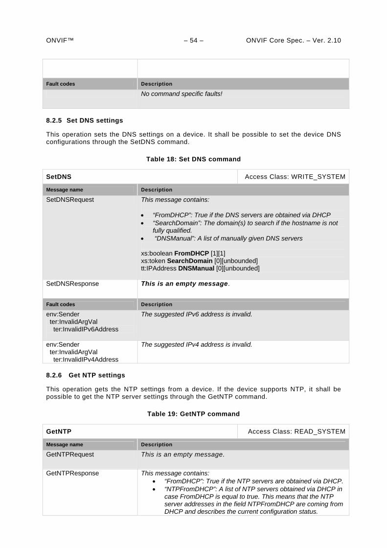
ONVIF™ – 54 – ONVIF Core Spec. – Ver. 2.10
Fault codes Description
No command specific faults!
8.2.5 Set DNS settings
This operation sets the DNS settings on a device. It shall be possible to set the device DNS configurations through the SetDNS command.
Table 18: Set DNS command
SetDNS Access Class: WRITE_SYSTEM
Message name Description
SetDNSRequest This message contains: “FromDHCP”: True if the DNS servers are obtained via DHCP “SearchDomain”: The domain(s) to search if the hostname is not
fully qualified. “DNSManual”: A list of manually given DNS servers xs:boolean FromDHCP [1][1] xs:token SearchDomain [0][unbounded] tt:IPAddress DNSManual [0][unbounded]
SetDNSResponse This is an empty message.
Fault codes Description
env:Sender ter:InvalidArgVal ter:InvalidIPv6Address
The suggested IPv6 address is invalid.
env:Sender ter:InvalidArgVal ter:InvalidIPv4Address
The suggested IPv4 address is invalid.
8.2.6 Get NTP settings
This operation gets the NTP settings from a device. If the device supports NTP, it shall be possible to get the NTP server settings through the GetNTP command.
Table 19: GetNTP command
GetNTP Access Class: READ_SYSTEM
Message name Description
GetNTPRequest This is an empty message.
GetNTPResponse This message contains: “FromDHCP”: True if the NTP servers are obtained via DHCP. “NTPFromDHCP”: A list of NTP servers obtained via DHCP in
case FromDHCP is equal to true. This means that the NTP server addresses in the field NTPFromDHCP are coming from DHCP and describes the current configuration status.
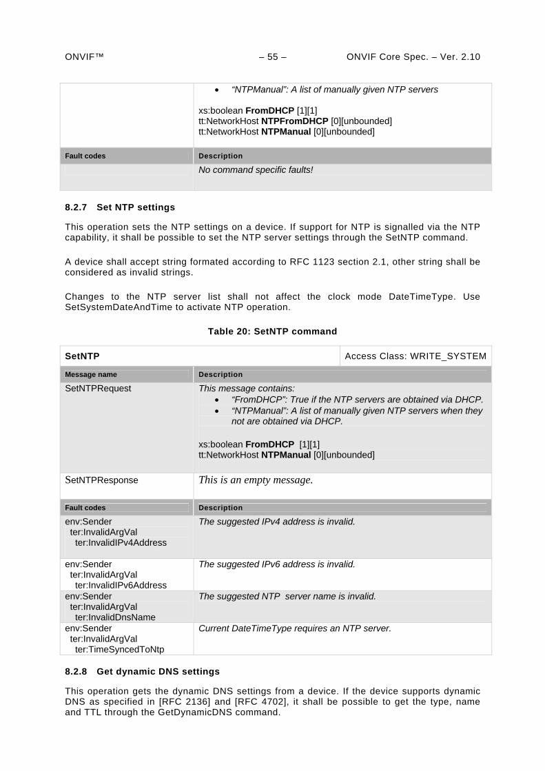
ONVIF™ – 55 – ONVIF Core Spec. – Ver. 2.10
“NTPManual”: A list of manually given NTP servers xs:boolean FromDHCP [1][1] tt:NetworkHost NTPFromDHCP [0][unbounded] tt:NetworkHost NTPManual [0][unbounded]
Fault codes Description
No command specific faults!
8.2.7 Set NTP settings
This operation sets the NTP settings on a device. If support for NTP is signalled via the NTP capability, it shall be possible to set the NTP server settings through the SetNTP command.
A device shall accept string formated according to RFC 1123 section 2.1, other string shall be considered as invalid strings.
Changes to the NTP server list shall not affect the clock mode DateTimeType. Use SetSystemDateAndTime to activate NTP operation.
Table 20: SetNTP command
SetNTP Access Class: WRITE_SYSTEM
Message name Description
SetNTPRequest This message contains: “FromDHCP”: True if the NTP servers are obtained via DHCP. “NTPManual”: A list of manually given NTP servers when they
not are obtained via DHCP. xs:boolean FromDHCP [1][1] tt:NetworkHost NTPManual [0][unbounded]
SetNTPResponse This is an empty message.
Fault codes Description
env:Sender ter:InvalidArgVal ter:InvalidIPv4Address
The suggested IPv4 address is invalid.
env:Sender ter:InvalidArgVal ter:InvalidIPv6Address
The suggested IPv6 address is invalid.
env:Sender ter:InvalidArgVal ter:InvalidDnsName
The suggested NTP server name is invalid.
env:Sender ter:InvalidArgVal ter:TimeSyncedToNtp
Current DateTimeType requires an NTP server.
8.2.8 Get dynamic DNS settings
This operation gets the dynamic DNS settings from a device. If the device supports dynamic DNS as specified in [RFC 2136] and [RFC 4702], it shall be possible to get the type, name and TTL through the GetDynamicDNS command.
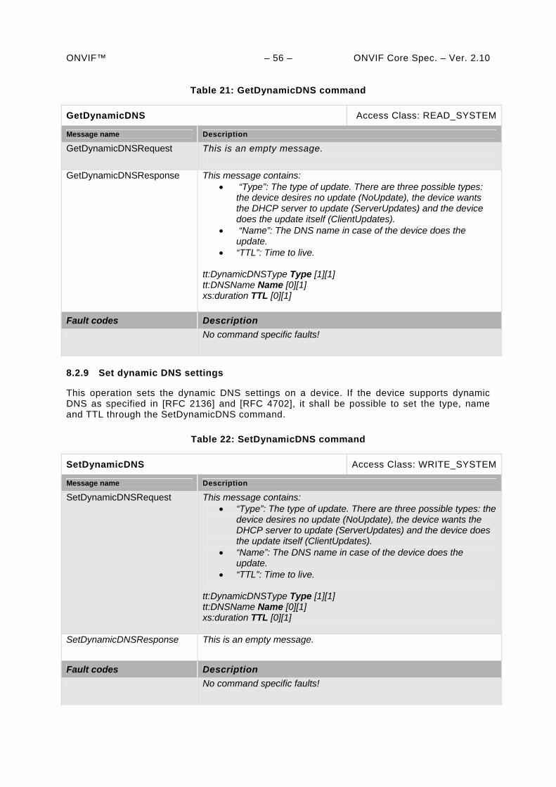
ONVIF™ – 56 – ONVIF Core Spec. – Ver. 2.10
Table 21: GetDynamicDNS command
GetDynamicDNS Access Class: READ_SYSTEM
Message name Description
GetDynamicDNSRequest This is an empty message.
GetDynamicDNSResponse This message contains: “Type”: The type of update. There are three possible types:
the device desires no update (NoUpdate), the device wants the DHCP server to update (ServerUpdates) and the device does the update itself (ClientUpdates).
“Name”: The DNS name in case of the device does the update.
“TTL”: Time to live. tt:DynamicDNSType Type [1][1] tt:DNSName Name [0][1] xs:duration TTL [0][1]
Fault codes Description
No command specific faults!
8.2.9 Set dynamic DNS settings
This operation sets the dynamic DNS settings on a device. If the device supports dynamic DNS as specified in [RFC 2136] and [RFC 4702], it shall be possible to set the type, name and TTL through the SetDynamicDNS command.
Table 22: SetDynamicDNS command
SetDynamicDNS Access Class: WRITE_SYSTEM
Message name Description
SetDynamicDNSRequest This message contains: “Type”: The type of update. There are three possible types: the
device desires no update (NoUpdate), the device wants the DHCP server to update (ServerUpdates) and the device does the update itself (ClientUpdates).
“Name”: The DNS name in case of the device does the update.
“TTL”: Time to live.
tt:DynamicDNSType Type [1][1] tt:DNSName Name [0][1] xs:duration TTL [0][1]
SetDynamicDNSResponse This is an empty message.
Fault codes Description
No command specific faults!
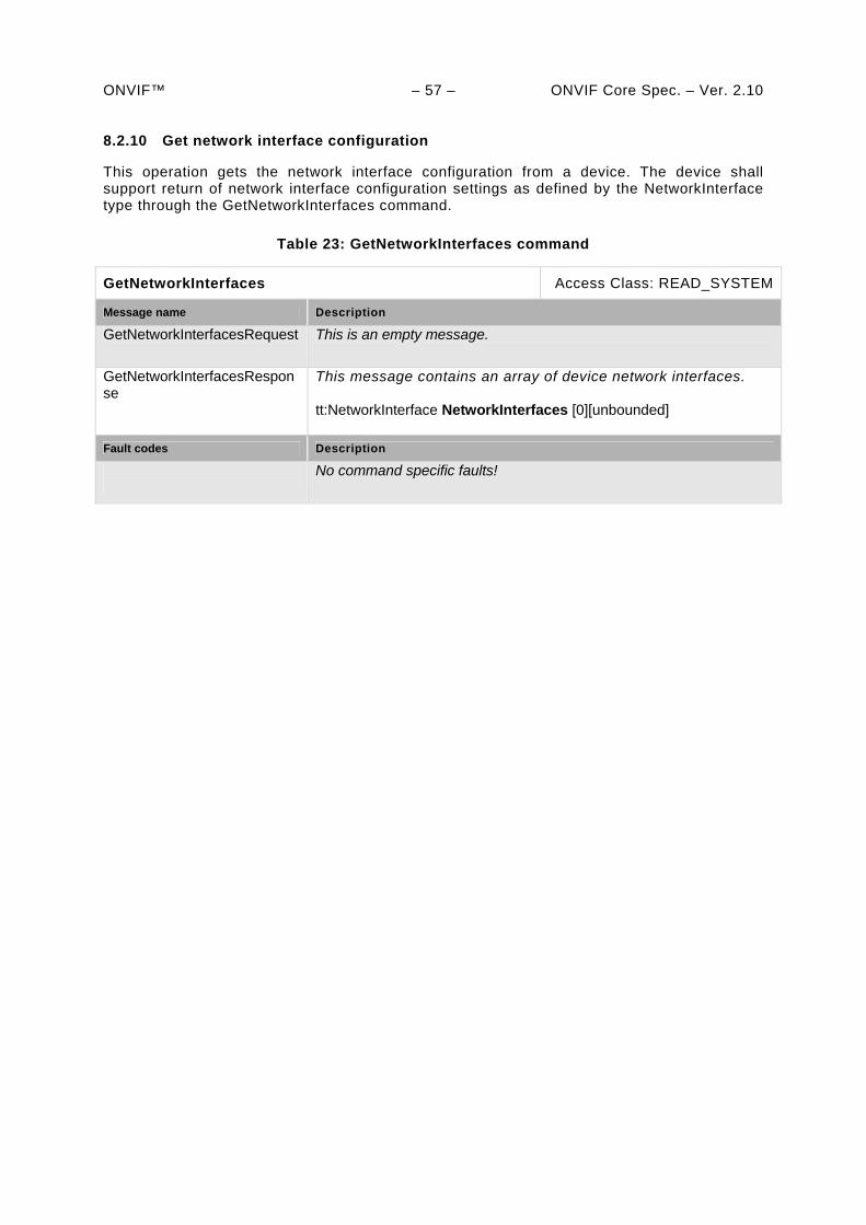
ONVIF™ – 57 – ONVIF Core Spec. – Ver. 2.10 8.2.10 Get network interface configuration
This operation gets the network interface configuration from a device. The device shall support return of network interface configuration settings as defined by the NetworkInterface type through the GetNetworkInterfaces command.
Table 23: GetNetworkInterfaces command
GetNetworkInterfaces Access Class: READ_SYSTEM
Message name Description
GetNetworkInterfacesRequest This is an empty message.
GetNetworkInterfacesResponse
This message contains an array of device network interfaces. tt:NetworkInterface NetworkInterfaces [0][unbounded]
Fault codes Description
No command specific faults!
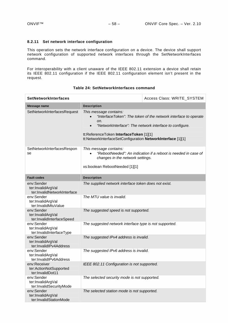
ONVIF™ – 58 – ONVIF Core Spec. – Ver. 2.10
8.2.11 Set network interface configuration
This operation sets the network interface configuration on a device. The device shall support network configuration of supported network interfaces through the SetNetworkInterfaces command.
For interoperability with a client unaware of the IEEE 802.11 extension a device shall retain its IEEE 802.11 configuration if the IEEE 802.11 configuration element isn’t present in the request.
Table 24: SetNetworkInterfaces command
SetNetworkInterfaces Access Class: WRITE_SYSTEM
Message name Description
SetNetworkInterfacesRequest This message contains: “InterfaceToken”: The token of the network interface to operate
on. “NetworkInterface”: The network interface to configure.
tt:ReferenceToken InterfaceToken [1][1] tt:NetworkInterfaceSetConfiguration NetworkInterface [1][1]
SetNetworkInterfacesResponse
This message contains: “RebootNeeded": An indication if a reboot is needed in case of
changes in the network settings.
xs:boolean RebootNeeded [1][1]
Fault codes Description
env:Sender ter:InvalidArgVal ter:InvalidNetworkInterface
The supplied network interface token does not exist.
env:Sender ter:InvalidArgVal ter:InvalidMtuValue
The MTU value is invalid.
env:Sender ter:InvalidArgVal ter:InvalidInterfaceSpeed
The suggested speed is not supported.
env:Sender ter:InvalidArgVal ter:InvalidInterfaceType
The suggested network interface type is not supported.
env:Sender ter:InvalidArgVal ter:InvalidIPv4Address
The suggested IPv4 address is invalid.
env:Sender ter:InvalidArgVal ter:InvalidIPv6Address
The suggested IPv6 address is invalid.
env:Receiver ter:ActionNotSupported ter:InvalidDot11
IEEE 802.11 Configuration is not supported.
env:Sender ter:InvalidArgVal ter:InvalidSecurityMode
The selected security mode is not supported.
env:Sender ter:InvalidArgVal ter:InvalidStationMode
The selected station mode is not supported.
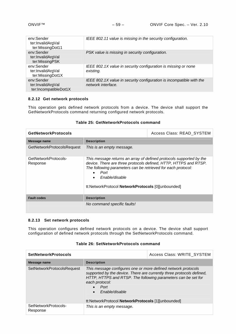
ONVIF™ – 59 – ONVIF Core Spec. – Ver. 2.10 env:Sender ter:InvalidArgVal ter:MissingDot11
IEEE 802.11 value is missing in the security configuration.
env:Sender ter:InvalidArgVal ter:MissingPSK
PSK value is missing in security configuration.
env:Sender ter:InvalidArgVal ter:MissingDot1X
IEEE 802.1X value in security configuration is missing or none existing.
env:Sender ter:InvalidArgVal ter:IncompatibleDot1X
IEEE 802.1X value in security configuration is incompatible with the network interface.
8.2.12 Get network protocols
This operation gets defined network protocols from a device. The device shall support the GetNetworkProtocols command returning configured network protocols.
Table 25: GetNetworkProtocols command
GetNetworkProtocols Access Class: READ_SYSTEM
Message name Description
GetNetworkProtocolsRequest This is an empty message.
GetNetworkProtocols-Response
This message returns an array of defined protocols supported by the device. There are three protocols defined, HTTP, HTTPS and RTSP. The following parameters can be retrieved for each protocol:
Port Enable/disable
tt:NetworkProtocol NetworkProtocols [0][unbounded]
Fault codes Description
No command specific faults!
8.2.13 Set network protocols
This operation configures defined network protocols on a device. The device shall support configuration of defined network protocols through the SetNetworkProtocols command.
Table 26: SetNetworkProtocols command
SetNetworkProtocols Access Class: WRITE_SYSTEM
Message name Description
SetNetworkProtocolsRequest This message configures one or more defined network protocols supported by the device. There are currently three protocols defined, HTTP, HTTPS and RTSP. The following parameters can be set for each protocol:
Port Enable/disable
tt:NetworkProtocol NetworkProtocols [1][unbounded]
SetNetworkProtocols-Response
This is an empty message.
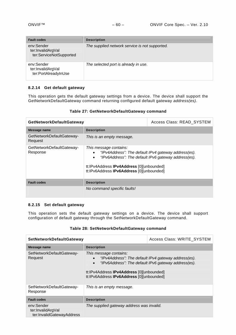
ONVIF™ – 60 – ONVIF Core Spec. – Ver. 2.10
Fault codes Description
env:Sender ter:InvalidArgVal ter:ServiceNotSupported
The supplied network service is not supported.
env:Sender ter:InvalidArgVal ter:PortAlreadyInUse
The selected port is already in use.
8.2.14 Get default gateway
This operation gets the default gateway settings from a device. The device shall support the GetNetworkDefaultGateway command returning configured default gateway address(es).
Table 27: GetNetworkDefaultGateway command
GetNetworkDefaultGateway Access Class: READ_SYSTEM
Message name Description
GetNetworkDefaultGateway-Request
This is an empty message.
GetNetworkDefaultGateway-Response
This message contains: “IPv4Address”: The default IPv4 gateway address(es). “IPv6Address”: The default IPv6 gateway address(es).
tt:IPv4Address IPv4Address [0][unbounded] tt:IPv6Address IPv6Address [0][unbounded]
Fault codes Description
No command specific faults!
8.2.15 Set default gateway
This operation sets the default gateway settings on a device. The device shall support configuration of default gateway through the SetNetworkDefaultGateway command.
Table 28: SetNetworkDefaultGateway command
SetNetworkDefaultGateway Access Class: WRITE_SYSTEM
Message name Description
SetNetworkDefaultGateway-Request
This message contains: “IPv4Address”: The default IPv4 gateway address(es). “IPv6Address”: The default IPv6 gateway address(es).
tt:IPv4Address IPv4Address [0][unbounded] tt:IPv6Address IPv6Address [0][unbounded]
SetNetworkDefaultGateway-Response
This is an empty message.
Fault codes Description
env:Sender ter:InvalidArgVal ter:InvalidGatewayAddress
The supplied gateway address was invalid.
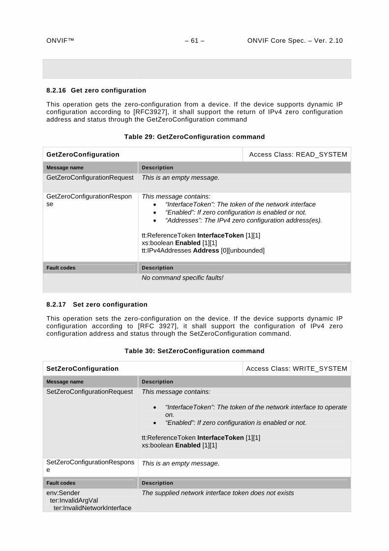
ONVIF™ – 61 – ONVIF Core Spec. – Ver. 2.10
8.2.16 Get zero configuration
This operation gets the zero-configuration from a device. If the device supports dynamic IP configuration according to [RFC3927], it shall support the return of IPv4 zero configuration address and status through the GetZeroConfiguration command
Table 29: GetZeroConfiguration command
GetZeroConfiguration Access Class: READ_SYSTEM
Message name Description
GetZeroConfigurationRequest This is an empty message.
GetZeroConfigurationResponse
This message contains: “InterfaceToken”: The token of the network interface “Enabled”: If zero configuration is enabled or not. “Addresses”: The IPv4 zero configuration address(es).
tt:ReferenceToken InterfaceToken [1][1] xs:boolean Enabled [1][1] tt:IPv4Addresses Address [0][unbounded]
Fault codes Description
No command specific faults!
8.2.17 Set zero configuration
This operation sets the zero-configuration on the device. If the device supports dynamic IP configuration according to [RFC 3927], it shall support the configuration of IPv4 zero configuration address and status through the SetZeroConfiguration command.
Table 30: SetZeroConfiguration command
SetZeroConfiguration Access Class: WRITE_SYSTEM
Message name Description
SetZeroConfigurationRequest This message contains:
“InterfaceToken”: The token of the network interface to operate on.
“Enabled”: If zero configuration is enabled or not. tt:ReferenceToken InterfaceToken [1][1] xs:boolean Enabled [1][1]
SetZeroConfigurationResponse
This is an empty message.
Fault codes Description
env:Sender ter:InvalidArgVal ter:InvalidNetworkInterface
The supplied network interface token does not exists
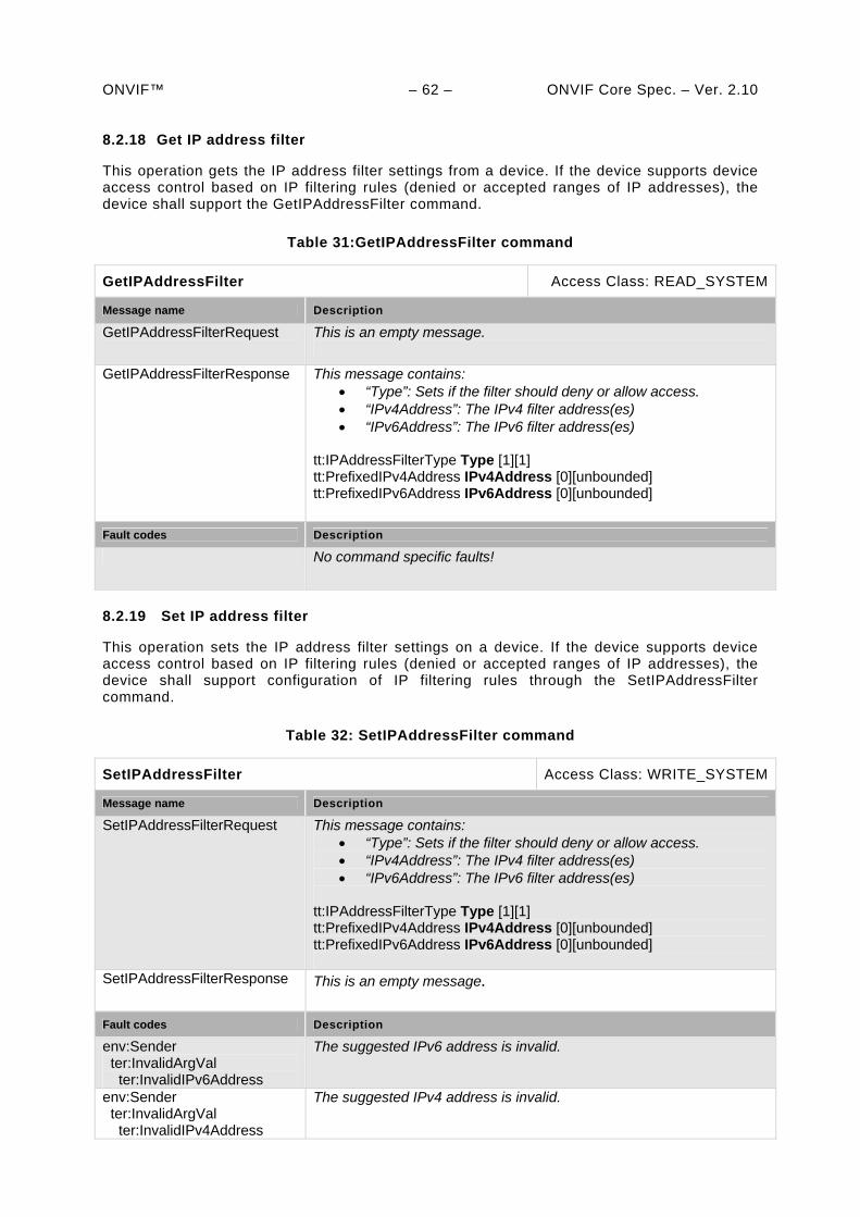
ONVIF™ – 62 – ONVIF Core Spec. – Ver. 2.10 8.2.18 Get IP address filter
This operation gets the IP address filter settings from a device. If the device supports device access control based on IP filtering rules (denied or accepted ranges of IP addresses), the device shall support the GetIPAddressFilter command.
Table 31:GetIPAddressFilter command
GetIPAddressFilter Access Class: READ_SYSTEM
Message name Description
GetIPAddressFilterRequest This is an empty message.
GetIPAddressFilterResponse This message contains: “Type”: Sets if the filter should deny or allow access. “IPv4Address”: The IPv4 filter address(es) “IPv6Address”: The IPv6 filter address(es)
tt:IPAddressFilterType Type [1][1] tt:PrefixedIPv4Address IPv4Address [0][unbounded] tt:PrefixedIPv6Address IPv6Address [0][unbounded]
Fault codes Description
No command specific faults!
8.2.19 Set IP address filter
This operation sets the IP address filter settings on a device. If the device supports device access control based on IP filtering rules (denied or accepted ranges of IP addresses), the device shall support configuration of IP filtering rules through the SetIPAddressFilter command.
Table 32: SetIPAddressFilter command
SetIPAddressFilter Access Class: WRITE_SYSTEM
Message name Description
SetIPAddressFilterRequest This message contains: “Type”: Sets if the filter should deny or allow access. “IPv4Address”: The IPv4 filter address(es) “IPv6Address”: The IPv6 filter address(es)
tt:IPAddressFilterType Type [1][1] tt:PrefixedIPv4Address IPv4Address [0][unbounded] tt:PrefixedIPv6Address IPv6Address [0][unbounded]
SetIPAddressFilterResponse This is an empty message.
Fault codes Description
env:Sender ter:InvalidArgVal ter:InvalidIPv6Address
The suggested IPv6 address is invalid.
env:Sender ter:InvalidArgVal ter:InvalidIPv4Address
The suggested IPv4 address is invalid.
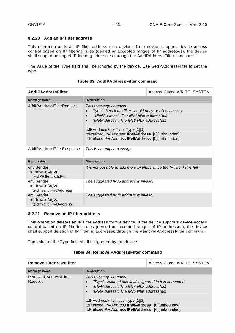
ONVIF™ – 63 – ONVIF Core Spec. – Ver. 2.10 8.2.20 Add an IP filter address
This operation adds an IP filter address to a device. If the device supports device access control based on IP filtering rules (denied or accepted ranges of IP addresses), the device shall support adding of IP filtering addresses through the AddIPAddressFilter command.
The value of the Type field shall be ignored by the device. Use SetIPAddressFilter to set the type.
Table 33: AddIPAddressFilter command
AddIPAddressFilter Access Class: WRITE_SYSTEM
Message name Description
AddIPAddressFilterRequest This message contains: Type”: Sets if the filter should deny or allow access. “IPv4Address”: The IPv4 filter address(es) “IPv6Address”: The IPv6 filter address(es) tt:IPAddressFilterType Type [1][1] tt:PrefixedIPv4Address IPv4Address [0][unbounded] tt:PrefixedIPv6Address IPv6Address [0][unbounded]
AddIPAddressFilterResponse This is an empty message.
Fault codes Description
env:Sender ter:InvalidArgVal ter:IPFilterListIsFull
It is not possible to add more IP filters since the IP filter list is full.
env:Sender ter:InvalidArgVal ter:InvalidIPv6Address
The suggested IPv6 address is invalid.
env:Sender ter:InvalidArgVal ter:InvalidIPv4Address
The suggested IPv4 address is invalid.
8.2.21 Remove an IP filter address
This operation deletes an IP filter address from a device. If the device supports device access control based on IP filtering rules (denied or accepted ranges of IP addresses), the device shall support deletion of IP filtering addresses through the RemoveIPAddressFilter command.
The value of the Type field shall be ignored by the device.
Table 34: RemoveIPAddressFilter command
RemoveIPAddressFilter Access Class: WRITE_SYSTEM
Message name Description
RemoveIPAddressFilter-Request
This message contains: “Type”: Value of this field is ignored in this command. “IPv4Address”: The IPv4 filter address(es) “IPv6Address”: The IPv6 filter address(es) tt:IPAddressFilterType Type [1][1] tt:PrefixedIPv4Address IPv4Address [0][unbounded] tt:PrefixedIPv6Address IPv6Address [0][unbounded]
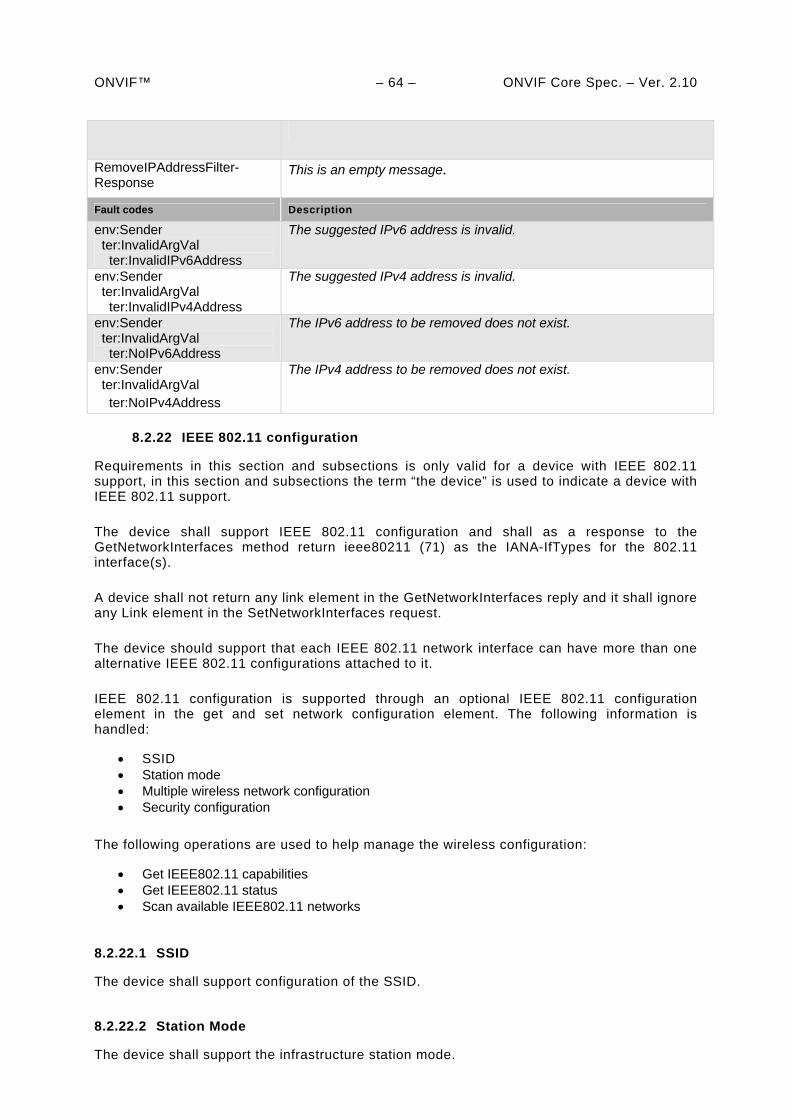
ONVIF™ – 64 – ONVIF Core Spec. – Ver. 2.10
RemoveIPAddressFilter-Response
This is an empty message.
Fault codes Description
env:Sender ter:InvalidArgVal ter:InvalidIPv6Address
The suggested IPv6 address is invalid.
env:Sender ter:InvalidArgVal ter:InvalidIPv4Address
The suggested IPv4 address is invalid.
env:Sender ter:InvalidArgVal ter:NoIPv6Address
The IPv6 address to be removed does not exist.
env:Sender ter:InvalidArgVal ter:NoIPv4Address
The IPv4 address to be removed does not exist.
8.2.22 IEEE 802.11 configuration
Requirements in this section and subsections is only valid for a device with IEEE 802.11 support, in this section and subsections the term “the device” is used to indicate a device with IEEE 802.11 support.
The device shall support IEEE 802.11 configuration and shall as a response to the GetNetworkInterfaces method return ieee80211 (71) as the IANA-IfTypes for the 802.11 interface(s).
A device shall not return any link element in the GetNetworkInterfaces reply and it shall ignore any Link element in the SetNetworkInterfaces request.
The device should support that each IEEE 802.11 network interface can have more than one alternative IEEE 802.11 configurations attached to it.
IEEE 802.11 configuration is supported through an optional IEEE 802.11 configuration element in the get and set network configuration element. The following information is handled:
SSID Station mode Multiple wireless network configuration Security configuration
The following operations are used to help manage the wireless configuration:
Get IEEE802.11 capabilities Get IEEE802.11 status Scan available IEEE802.11 networks
8.2.22.1 SSID
The device shall support configuration of the SSID.
8.2.22.2 Station Mode
The device shall support the infrastructure station mode.
ONVIF™ – 65 – ONVIF Core Spec. – Ver. 2.10 The device may support the ad-hoc network station mode. The actual configuration needed for ad-hoc network station mode, including manual configuration of the channel number, is outside the scope of this specification; But to allow for devices that support ad-hoc network station modes, the specification allows for selecting (and reporting) this mode.
8.2.22.3 Multiple wireless network configuration
Each IEEE 802.11 configuration shall be identified with an alias (identifier). The alias shall be unique within a network interface configuration. The client shall supply the alias in the SetNetworkInterfaces request. If the client wants to update an existing wireless configuration the same alias shall be used. A wireless configuration, including the alias, shall only exist while it’s part of a network interface configuration.
For the device to be able to prioritize between multiple alternative IEEE802.11 configurations an optional priority value can be used, a higher value means a higher priority. If the priority value is missing from the configuration the lowest priority shall be assumed. If several wireless configurations have the same priority value the order between those configurations is undefined.
The actual algorithm used by the device to enable an IEEE 802.11 network from the prioritized list of IEEE 802.11 configurations is outside the scope of this specification.
8.2.22.4 Security configuration
The security configuration contains the chosen security mode and the configuration needed for that mode. The following security modes are supported:
None PSK (Pre Shared Key) (WPA- and WPA2-Personal) IEEE 802.1X-2004 (WPA- and WPA2-Enterpise)
Configuration of WEP security mode is outside the scope of this speciation but to allow for devices that support WEP security mode this specification allows for selecting (and reporting) this mode.
For data confidentiality and integrity the device shall, in accordance with the [IEEE 802.11-2007] specification, support the CCMP algorithm and the device may support the TKIP algorithm.
The algorithm can either be manually (CCMP, TKIP) or automatically (Any) selected. In manual selected mode the same algorithm shall be used for both the pairwise and group cipher. To be able to support other algorithms an “Extended” value is available.
The device shall support both the manually and the automatically selected mode.
8.2.22.4.1 None mode
The device shall support the “None” security mode.
8.2.22.4.2 PSK mode
The device shall support the PSK security mode.
To minimise the risk for compromising the PSK the device should not transmit any PSK to a client, furthermore it shall not return the PSK in a response to a GetNetworkInterfaces operation call.
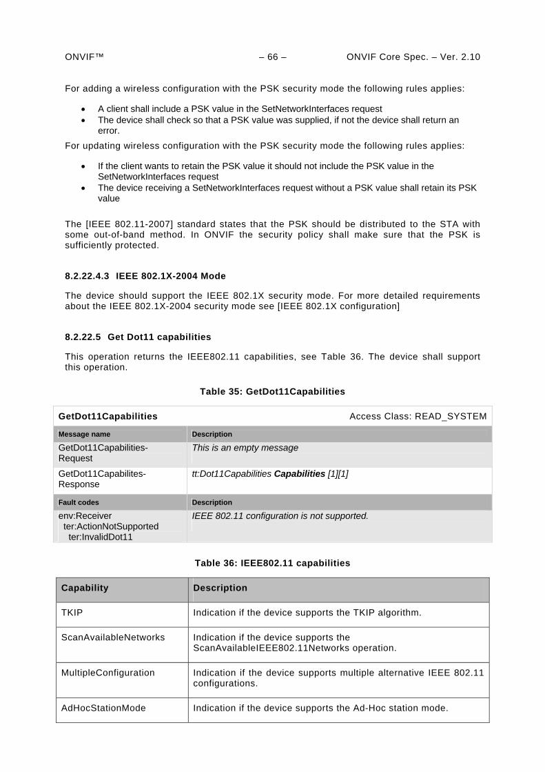
ONVIF™ – 66 – ONVIF Core Spec. – Ver. 2.10 For adding a wireless configuration with the PSK security mode the following rules applies:
A client shall include a PSK value in the SetNetworkInterfaces request The device shall check so that a PSK value was supplied, if not the device shall return an
error.
For updating wireless configuration with the PSK security mode the following rules applies:
If the client wants to retain the PSK value it should not include the PSK value in the SetNetworkInterfaces request
The device receiving a SetNetworkInterfaces request without a PSK value shall retain its PSK value
The [IEEE 802.11-2007] standard states that the PSK should be distributed to the STA with some out-of-band method. In ONVIF the security policy shall make sure that the PSK is sufficiently protected.
8.2.22.4.3 IEEE 802.1X-2004 Mode
The device should support the IEEE 802.1X security mode. For more detailed requirements about the IEEE 802.1X-2004 security mode see [IEEE 802.1X configuration]
8.2.22.5 Get Dot11 capabilities
This operation returns the IEEE802.11 capabilities, see Table 36. The device shall support this operation.
Table 35: GetDot11Capabilities
GetDot11Capabilities Access Class: READ_SYSTEM
Message name Description
GetDot11Capabilities-Request
This is an empty message
GetDot11Capabilites-Response
tt:Dot11Capabilities Capabilities [1][1]
Fault codes Description
env:Receiver ter:ActionNotSupported ter:InvalidDot11
IEEE 802.11 configuration is not supported.
Table 36: IEEE802.11 capabilities
Capability Description
TKIP Indication if the device supports the TKIP algorithm.
ScanAvailableNetworks Indication if the device supports the ScanAvailableIEEE802.11Networks operation.
MultipleConfiguration Indication if the device supports multiple alternative IEEE 802.11 configurations.
AdHocStationMode Indication if the device supports the Ad-Hoc station mode.
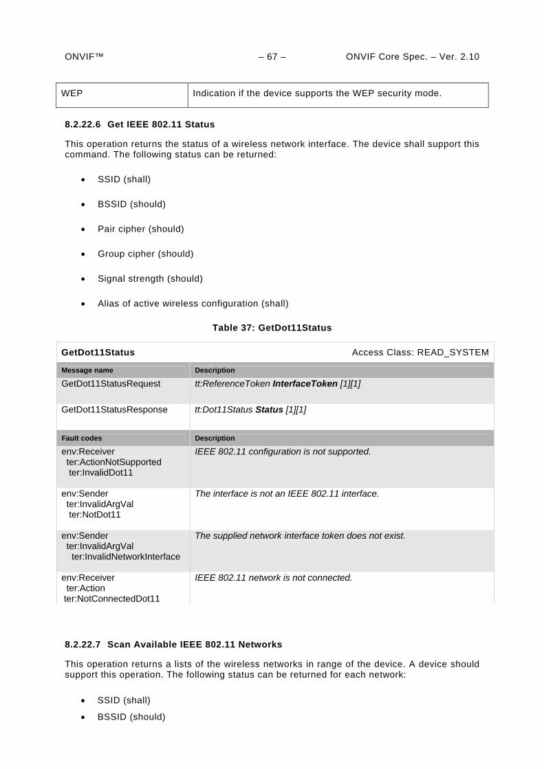
ONVIF™ – 67 – ONVIF Core Spec. – Ver. 2.10
WEP Indication if the device supports the WEP security mode.
8.2.22.6 Get IEEE 802.11 Status
This operation returns the status of a wireless network interface. The device shall support this command. The following status can be returned:
SSID (shall)
BSSID (should)
Pair cipher (should)
Group cipher (should)
Signal strength (should)
Alias of active wireless configuration (shall)
Table 37: GetDot11Status
GetDot11Status Access Class: READ_SYSTEM
Message name Description
GetDot11StatusRequest tt:ReferenceToken InterfaceToken [1][1]
GetDot11StatusResponse tt:Dot11Status Status [1][1]
Fault codes Description
env:Receiver ter:ActionNotSupported ter:InvalidDot11
IEEE 802.11 configuration is not supported.
env:Sender ter:InvalidArgVal ter:NotDot11
The interface is not an IEEE 802.11 interface.
env:Sender ter:InvalidArgVal ter:InvalidNetworkInterface
The supplied network interface token does not exist.
env:Receiver ter:Action ter:NotConnectedDot11
IEEE 802.11 network is not connected.
8.2.22.7 Scan Available IEEE 802.11 Networks
This operation returns a lists of the wireless networks in range of the device. A device should support this operation. The following status can be returned for each network:
SSID (shall)
BSSID (should)
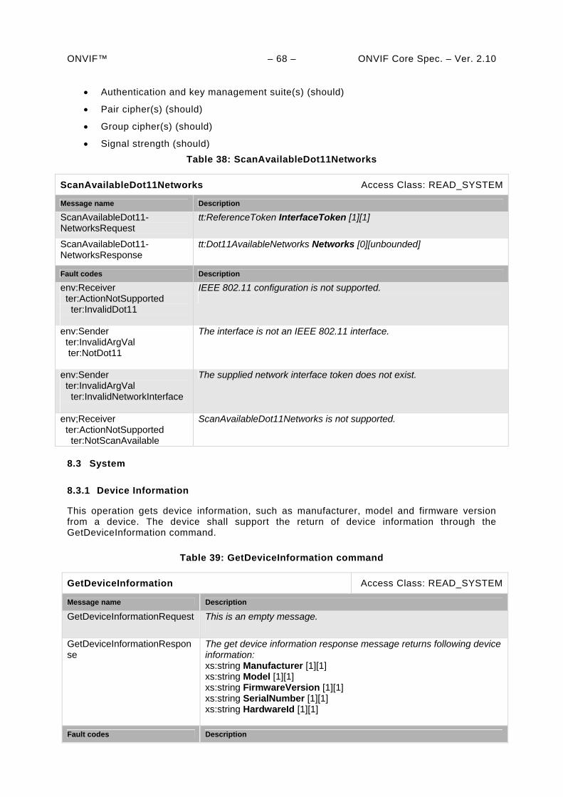
ONVIF™ – 68 – ONVIF Core Spec. – Ver. 2.10
Authentication and key management suite(s) (should)
Pair cipher(s) (should)
Group cipher(s) (should)
Signal strength (should)
Table 38: ScanAvailableDot11Networks
ScanAvailableDot11Networks Access Class: READ_SYSTEM
Message name Description
ScanAvailableDot11-NetworksRequest
tt:ReferenceToken InterfaceToken [1][1]
ScanAvailableDot11-NetworksResponse
tt:Dot11AvailableNetworks Networks [0][unbounded]
Fault codes Description
env:Receiver ter:ActionNotSupported ter:InvalidDot11
IEEE 802.11 configuration is not supported.
env:Sender ter:InvalidArgVal ter:NotDot11
The interface is not an IEEE 802.11 interface.
env:Sender ter:InvalidArgVal ter:InvalidNetworkInterface
The supplied network interface token does not exist.
env;Receiver ter:ActionNotSupported ter:NotScanAvailable
ScanAvailableDot11Networks is not supported.
8.3 System
8.3.1 Device Information
This operation gets device information, such as manufacturer, model and firmware version from a device. The device shall support the return of device information through the GetDeviceInformation command.
Table 39: GetDeviceInformation command
GetDeviceInformation Access Class: READ_SYSTEM
Message name Description
GetDeviceInformationRequest This is an empty message.
GetDeviceInformationResponse
The get device information response message returns following device information: xs:string Manufacturer [1][1] xs:string Model [1][1] xs:string FirmwareVersion [1][1] xs:string SerialNumber [1][1] xs:string HardwareId [1][1]
Fault codes Description
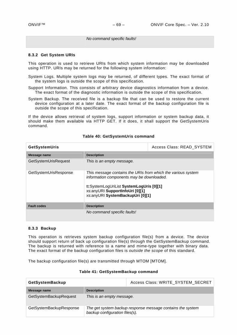
ONVIF™ – 69 – ONVIF Core Spec. – Ver. 2.10 No command specific faults!
8.3.2 Get System URIs
This operation is used to retrieve URIs from which system information may be downloaded using HTTP. URIs may be returned for the following system information:
System Logs. Multiple system logs may be returned, of different types. The exact format of the system logs is outside the scope of this specification.
Support Information. This consists of arbitrary device diagnostics information from a device. The exact format of the diagnostic information is outside the scope of this specification.
System Backup. The received file is a backup file that can be used to restore the current device configuration at a later date. The exact format of the backup configuration file is outside the scope of this specification.
If the device allows retrieval of system logs, support information or system backup data, it should make them available via HTTP GET. If it does, it shall support the GetSystemUris command.
Table 40: GetSystemUris command
GetSystemUris Access Class: READ_SYSTEM
Message name Description
GetSystemUrisRequest This is an empty message.
GetSystemUrisResponse This message contains the URIs from which the various system information components may be downloaded. tt:SystemLogUriList SystemLogUris [0][1] xs:anyURI SupportInfoUri [0][1] xs:anyURI SystemBackupUri [0][1]
Fault codes Description
No command specific faults!
8.3.3 Backup
This operation is retrieves system backup configuration file(s) from a device. The device should support return of back up configuration file(s) through the GetSystemBackup command. The backup is returned with reference to a name and mime-type together with binary data. The exact format of the backup configuration files is outside the scope of this standard.
The backup configuration file(s) are transmitted through MTOM [MTOM].
Table 41: GetSystemBackup command
GetSystemBackup Access Class: WRITE_SYSTEM_SECRET
Message name Description
GetSystemBackupRequest This is an empty message.
GetSystemBackupResponse The get system backup response message contains the system backup configuration files(s).
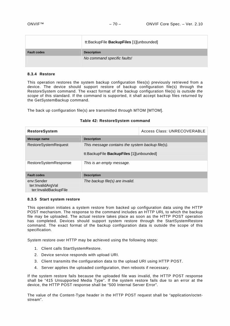
ONVIF™ – 70 – ONVIF Core Spec. – Ver. 2.10
tt:BackupFile BackupFiles [1][unbounded]
Fault codes Description
No command specific faults!
8.3.4 Restore
This operation restores the system backup configuration files(s) previously retrieved from a device. The device should support restore of backup configuration file(s) through the RestoreSystem command. The exact format of the backup configuration file(s) is outside the scope of this standard. If the command is supported, it shall accept backup files returned by the GetSystemBackup command.
The back up configuration file(s) are transmitted through MTOM [MTOM].
Table 42: RestoreSystem command
RestoreSystem Access Class: UNRECOVERABLE
Message name Description
RestoreSystemRequest This message contains the system backup file(s). tt:BackupFile BackupFiles [1][unbounded]
RestoreSystemResponse This is an empty message.
Fault codes Description
env:Sender ter:InvalidArgVal ter:InvalidBackupFile
The backup file(s) are invalid.
8.3.5 Start system restore
This operation initiates a system restore from backed up configuration data using the HTTP POST mechanism. The response to the command includes an HTTP URL to which the backup file may be uploaded. The actual restore takes place as soon as the HTTP POST operation has completed. Devices should support system restore through the StartSystemRestore command. The exact format of the backup configuration data is outside the scope of this specification.
System restore over HTTP may be achieved using the following steps:
1. Client calls StartSystemRestore.
2. Device service responds with upload URI.
3. Client transmits the configuration data to the upload URI using HTTP POST.
4. Server applies the uploaded configuration, then reboots if necessary.
If the system restore fails because the uploaded file was invalid, the HTTP POST response shall be “415 Unsupported Media Type”. If the system restore fails due to an error at the device, the HTTP POST response shall be “500 Internal Server Error”.
The value of the Content-Type header in the HTTP POST request shall be “application/octet-stream”.
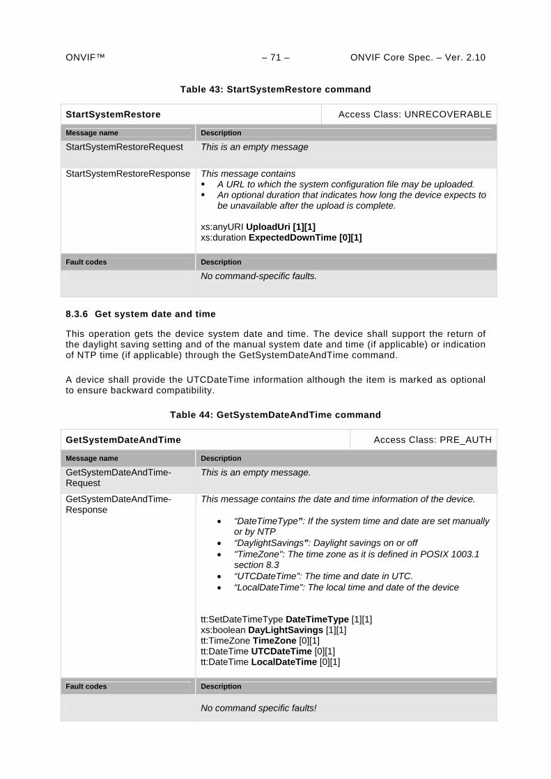
ONVIF™ – 71 – ONVIF Core Spec. – Ver. 2.10
Table 43: StartSystemRestore command
StartSystemRestore Access Class: UNRECOVERABLE
Message name Description
StartSystemRestoreRequest This is an empty message
StartSystemRestoreResponse This message contains A URL to which the system configuration file may be uploaded. An optional duration that indicates how long the device expects to
be unavailable after the upload is complete. xs:anyURI UploadUri [1][1] xs:duration ExpectedDownTime [0][1]
Fault codes Description
No command-specific faults.
8.3.6 Get system date and time
This operation gets the device system date and time. The device shall support the return of the daylight saving setting and of the manual system date and time (if applicable) or indication of NTP time (if applicable) through the GetSystemDateAndTime command.
A device shall provide the UTCDateTime information although the item is marked as optional to ensure backward compatibility.
Table 44: GetSystemDateAndTime command
GetSystemDateAndTime Access Class: PRE_AUTH
Message name Description
GetSystemDateAndTime-Request
This is an empty message.
GetSystemDateAndTime-Response
This message contains the date and time information of the device.
“DateTimeType”: If the system time and date are set manually or by NTP
“DaylightSavings”: Daylight savings on or off "TimeZone": The time zone as it is defined in POSIX 1003.1
section 8.3 “UTCDateTime”: The time and date in UTC. “LocalDateTime”: The local time and date of the device
tt:SetDateTimeType DateTimeType [1][1] xs:boolean DayLightSavings [1][1] tt:TimeZone TimeZone [0][1] tt:DateTime UTCDateTime [0][1] tt:DateTime LocalDateTime [0][1]
Fault codes Description
No command specific faults!
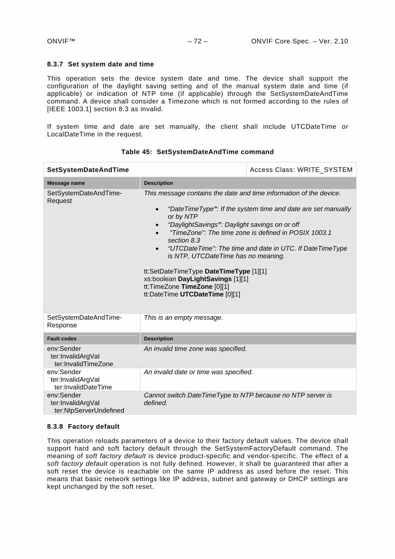
ONVIF™ – 72 – ONVIF Core Spec. – Ver. 2.10 8.3.7 Set system date and time
This operation sets the device system date and time. The device shall support the configuration of the daylight saving setting and of the manual system date and time (if applicable) or indication of NTP time (if applicable) through the SetSystemDateAndTime command. A device shall consider a Timezone which is not formed according to the rules of [IEEE 1003.1] section 8.3 as invalid.
If system time and date are set manually, the client shall include UTCDateTime or LocalDateTime in the request.
Table 45: SetSystemDateAndTime command
SetSystemDateAndTime Access Class: WRITE_SYSTEM
Message name Description
SetSystemDateAndTime-Request
This message contains the date and time information of the device.
“DateTimeType”: If the system time and date are set manually or by NTP
“DaylightSavings”: Daylight savings on or off "TimeZone": The time zone is defined in POSIX 1003.1
section 8.3 “UTCDateTime”: The time and date in UTC. If DateTimeType
is NTP, UTCDateTime has no meaning. tt:SetDateTimeType DateTimeType [1][1] xs:boolean DayLightSavings [1][1] tt:TimeZone TimeZone [0][1] tt:DateTime UTCDateTime [0][1]
SetSystemDateAndTime-Response
This is an empty message.
Fault codes Description
env:Sender ter:InvalidArgVal ter:InvalidTimeZone
An invalid time zone was specified.
env:Sender ter:InvalidArgVal ter:InvalidDateTime
An invalid date or time was specified.
env:Sender ter:InvalidArgVal ter:NtpServerUndefined
Cannot switch DateTimeType to NTP because no NTP server is defined.
8.3.8 Factory default
This operation reloads parameters of a device to their factory default values. The device shall support hard and soft factory default through the SetSystemFactoryDefault command. The meaning of soft factory default is device product-specific and vendor-specific. The effect of a soft factory default operation is not fully defined. However, it shall be guaranteed that after a soft reset the device is reachable on the same IP address as used before the reset. This means that basic network settings like IP address, subnet and gateway or DHCP settings are kept unchanged by the soft reset.
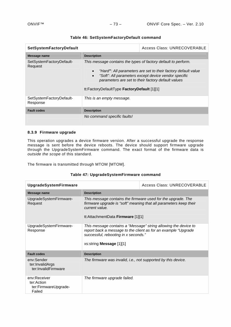
ONVIF™ – 73 – ONVIF Core Spec. – Ver. 2.10
Table 46: SetSystemFactoryDefault command
SetSystemFactoryDefault Access Class: UNRECOVERABLE
Message name Description
SetSystemFactoryDefault-Request
This message contains the types of factory default to perform.
“Hard”: All parameters are set to their factory default value “Soft”: All parameters except device vendor specific
parameters are set to their factory default values tt:FactoryDefaultType FactoryDefault [1][1]
SetSystemFactoryDefault-Response
This is an empty message.
Fault codes Description
No command specific faults!
8.3.9 Firmware upgrade
This operation upgrades a device firmware version. After a successful upgrade the response message is sent before the device reboots. The device should support firmware upgrade through the UpgradeSystemFirmware command. The exact format of the firmware data is outside the scope of this standard.
The firmware is transmitted through MTOM [MTOM].
Table 47: UpgradeSystemFirmware command
UpgradeSystemFirmware Access Class: UNRECOVERABLE
Message name Description
UpgradeSystemFirmware-Request
This message contains the firmware used for the upgrade. The firmware upgrade is “soft” meaning that all parameters keep their current value. tt:AttachmentData Firmware [1][1]
UpgradeSystemFirmware-Response
This message contains a “Message” string allowing the device to report back a message to the client as for an example “Upgrade successful, rebooting in x seconds.” xs:string Message [1][1]
Fault codes Description
env:Sender ter:InvalidArgs ter:InvalidFirmware
The firmware was invalid, i.e., not supported by this device.
env:Receiver ter:Action ter:FirmwareUpgrade- Failed
The firmware upgrade failed.
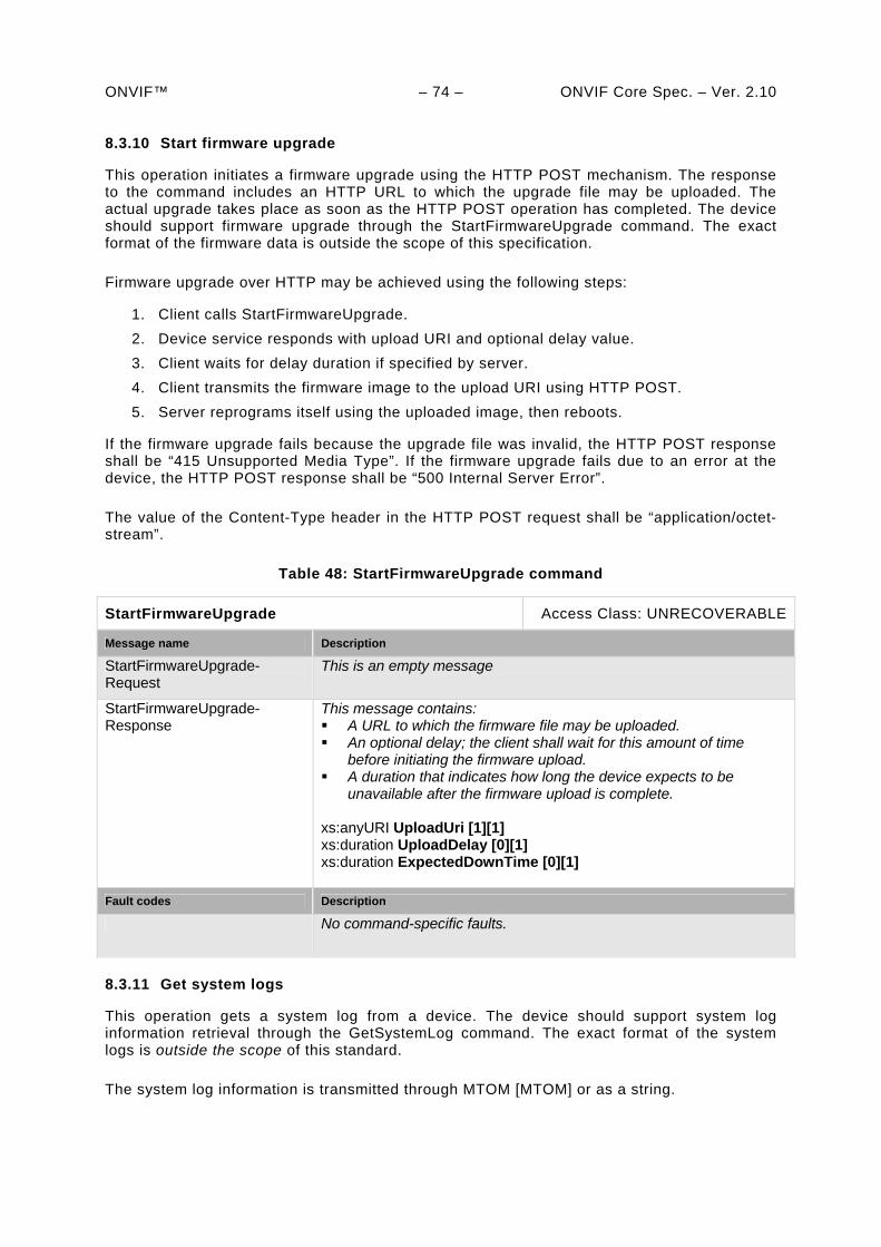
ONVIF™ – 74 – ONVIF Core Spec. – Ver. 2.10 8.3.10 Start firmware upgrade
This operation initiates a firmware upgrade using the HTTP POST mechanism. The response to the command includes an HTTP URL to which the upgrade file may be uploaded. The actual upgrade takes place as soon as the HTTP POST operation has completed. The device should support firmware upgrade through the StartFirmwareUpgrade command. The exact format of the firmware data is outside the scope of this specification.
Firmware upgrade over HTTP may be achieved using the following steps:
1. Client calls StartFirmwareUpgrade.
2. Device service responds with upload URI and optional delay value.
3. Client waits for delay duration if specified by server.
4. Client transmits the firmware image to the upload URI using HTTP POST.
5. Server reprograms itself using the uploaded image, then reboots.
If the firmware upgrade fails because the upgrade file was invalid, the HTTP POST response shall be “415 Unsupported Media Type”. If the firmware upgrade fails due to an error at the device, the HTTP POST response shall be “500 Internal Server Error”.
The value of the Content-Type header in the HTTP POST request shall be “application/octet-stream”.
Table 48: StartFirmwareUpgrade command
StartFirmwareUpgrade Access Class: UNRECOVERABLE
Message name Description
StartFirmwareUpgrade-Request
This is an empty message
StartFirmwareUpgrade-Response
This message contains: A URL to which the firmware file may be uploaded. An optional delay; the client shall wait for this amount of time
before initiating the firmware upload. A duration that indicates how long the device expects to be
unavailable after the firmware upload is complete. xs:anyURI UploadUri [1][1] xs:duration UploadDelay [0][1] xs:duration ExpectedDownTime [0][1]
Fault codes Description
No command-specific faults.
8.3.11 Get system logs
This operation gets a system log from a device. The device should support system log information retrieval through the GetSystemLog command. The exact format of the system logs is outside the scope of this standard.
The system log information is transmitted through MTOM [MTOM] or as a string.
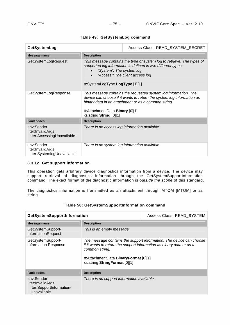
ONVIF™ – 75 – ONVIF Core Spec. – Ver. 2.10
Table 49: GetSystemLog command
GetSystemLog Access Class: READ_SYSTEM_SECRET
Message name Description
GetSystemLogRequest This message contains the type of system log to retrieve. The types of supported log information is defined in two different types:
“System”: The system log “Access”: The client access log
tt:SystemLogType LogType [1][1]
GetSystemLogResponse
This message contains the requested system log information. The device can choose if it wants to return the system log information as binary data in an attachment or as a common string. tt:AttachmentData Binary [0][1] xs:string String [0][1]
Fault codes Description
env:Sender ter:InvalidArgs ter:AccesslogUnavailable
There is no access log information available
env:Sender ter:InvalidArgs ter:SystemlogUnavailable
There is no system log information available
8.3.12 Get support information
This operation gets arbitrary device diagnostics information from a device. The device may support retrieval of diagnostics information through the GetSystemSupportInformation command. The exact format of the diagnostic information is outside the scope of this standard.
The diagnostics information is transmitted as an attachment through MTOM [MTOM] or as string.
Table 50: GetSystemSupportInformation command
GetSystemSupportInformation Access Class: READ_SYSTEM
Message name Description
GetSystemSupport-InformationRequest
This is an empty message.
GetSystemSupport-Information Response
The message contains the support information. The device can choose if it wants to return the support information as binary data or as a common string. tt:AttachmentData BinaryFormat [0][1] xs:string StringFormat [0][1]
Fault codes Description
env:Sender ter:InvalidArgs ter:SupportInformation- Unavailable
There is no support information available.
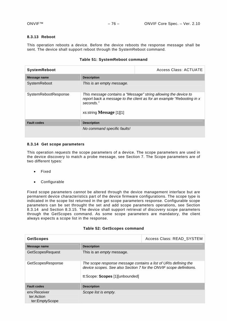
ONVIF™ – 76 – ONVIF Core Spec. – Ver. 2.10 8.3.13 Reboot
This operation reboots a device. Before the device reboots the response message shall be sent. The device shall support reboot through the SystemReboot command.
Table 51: SystemReboot command
SystemReboot Access Class: ACTUATE
Message name Description
SystemReboot This is an empty message.
SystemRebootResponse This message contains a “Message” string allowing the device to report back a message to the client as for an example “Rebooting in x seconds.” xs:string Message [1][1]
Fault codes Description
No command specific faults!
8.3.14 Get scope parameters
This operation requests the scope parameters of a device. The scope parameters are used in the device discovery to match a probe message, see Section 7. The Scope parameters are of two different types:
Fixed
Configurable
Fixed scope parameters cannot be altered through the device management interface but are permanent device characteristics part of the device firmware configurations. The scope type is indicated in the scope list returned in the get scope parameters response. Configurable scope parameters can be set throught the set and add scope parameters operations, see Section 8.3.14 and Section 8.3.15. The device shall support retrieval of discovery scope parameters through the GetScopes command. As some scope parameters are mandatory, the client always expects a scope list in the response.
Table 52: GetScopes command
GetScopes Access Class: READ_SYSTEM
Message name Description
GetScopesRequest This is an empty message.
GetScopesResponse The scope response message contains a list of URIs defining the device scopes. See also Section 7 for the ONVIF scope definitions. tt:Scope: Scopes [1][unbounded]
Fault codes Description
env:Receiver ter:Action ter:EmptyScope
Scope list is empty.

ONVIF™ – 77 – ONVIF Core Spec. – Ver. 2.10 8.3.15 Set scope parameters
This operation sets the scope parameters of a device. The scope parameters are used in the device discovery to match a probe message, see Section 7.
This operation replaces all existing configurable scope parameters (not fixed parameters). If this shall be avoided, one should use the scope add command instead. The device shall support configuration of discovery scope parameters through the SetScopes command.
Table 53: SetScopes command
SetScopes Access Class: WRITE_SYSTEM
Message name Description
SetScopesRequest The set scope contains a list of URIs defining the device scope. See also Section 7. xs:anyURI: Scopes [1][unbounded]
SetScopesResponse This is an empty message.
Fault codes Description
env:Sender ter:OperationProhibited ter:ScopeOverwrite
Scope parameter overwrites fixed device scope setting, command rejected.
env:Receiver ter:Action ter:TooManyScopes
The requested scope list exceeds the supported number of scopes.
8.3.16 Add scope parameters
This operation adds new configurable scope parameters to a device. The scope parameters are used in the device discovery to match a probe message, see Section 7. The device shall support addition of discovery scope parameters through the AddScopes command.
Table 54: AddScopes command
AddScopes Access Class: WRITE_SYSTEM
Message name Description
AddScopesRequest The add scope contains a list of URIs to be added to the existing configurable scope list. See also Section 7.. xs:anyURI:ScopeItem [1][unbounded]
AddScopesResponse This is an empty message.
Fault codes Description
env:Receiver ter:Action ter:TooManyScopes
The requested scope list exceeds the supported number of scopes.
8.3.17 Remove scope parameters
This operation deletes scope-configurable scope parameters from a device. The scope parameters are used in the device discovery to match a probe message, see Section 7. The
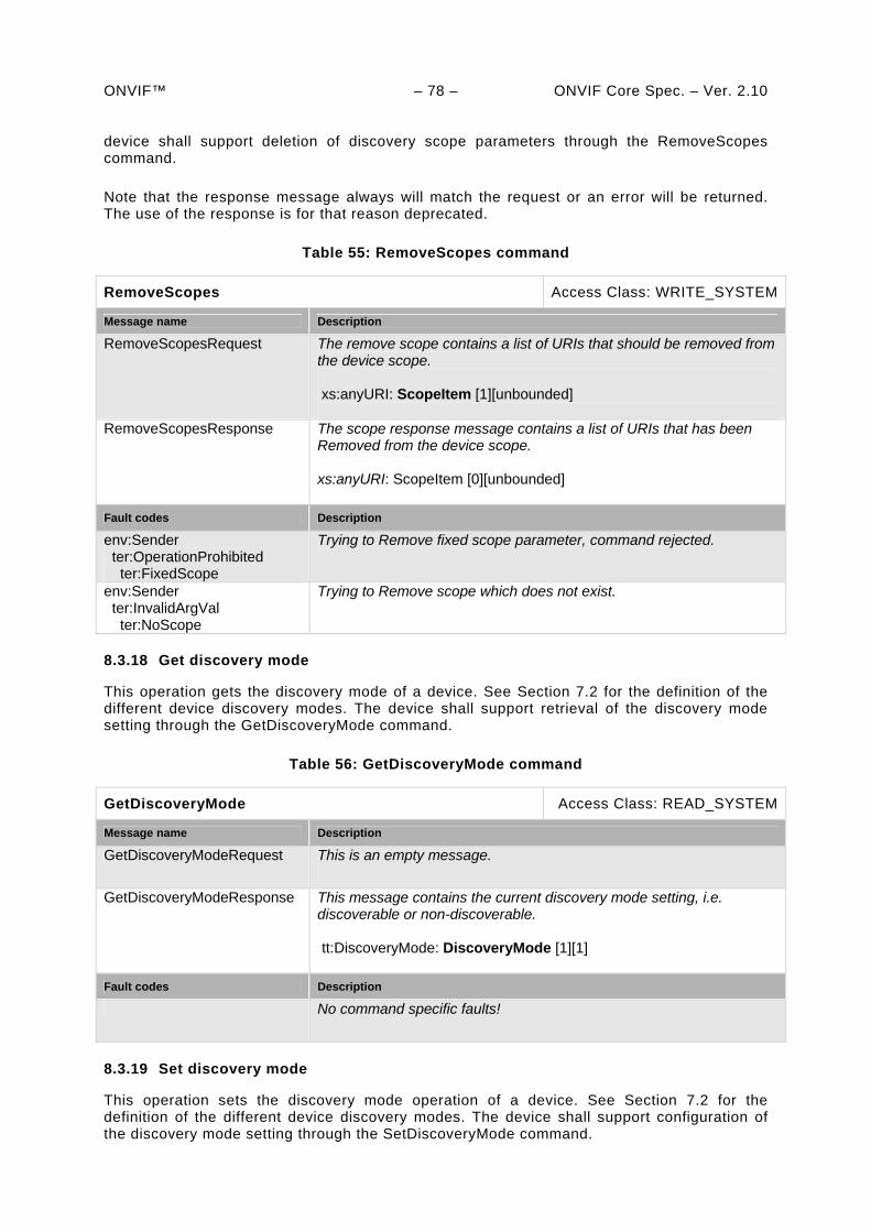
ONVIF™ – 78 – ONVIF Core Spec. – Ver. 2.10 device shall support deletion of discovery scope parameters through the RemoveScopes command.
Note that the response message always will match the request or an error will be returned. The use of the response is for that reason deprecated.
Table 55: RemoveScopes command
RemoveScopes Access Class: WRITE_SYSTEM
Message name Description
RemoveScopesRequest The remove scope contains a list of URIs that should be removed from the device scope. xs:anyURI: ScopeItem [1][unbounded]
RemoveScopesResponse The scope response message contains a list of URIs that has been Removed from the device scope. xs:anyURI: ScopeItem [0][unbounded]
Fault codes Description
env:Sender ter:OperationProhibited ter:FixedScope
Trying to Remove fixed scope parameter, command rejected.
env:Sender ter:InvalidArgVal ter:NoScope
Trying to Remove scope which does not exist.
8.3.18 Get discovery mode
This operation gets the discovery mode of a device. See Section 7.2 for the definition of the different device discovery modes. The device shall support retrieval of the discovery mode setting through the GetDiscoveryMode command.
Table 56: GetDiscoveryMode command
GetDiscoveryMode Access Class: READ_SYSTEM
Message name Description
GetDiscoveryModeRequest This is an empty message.
GetDiscoveryModeResponse This message contains the current discovery mode setting, i.e. discoverable or non-discoverable. tt:DiscoveryMode: DiscoveryMode [1][1]
Fault codes Description
No command specific faults!
8.3.19 Set discovery mode
This operation sets the discovery mode operation of a device. See Section 7.2 for the definition of the different device discovery modes. The device shall support configuration of the discovery mode setting through the SetDiscoveryMode command.
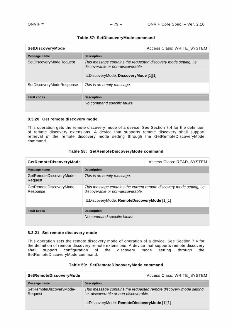
ONVIF™ – 79 – ONVIF Core Spec. – Ver. 2.10
Table 57: SetDiscoveryMode command
SetDiscoveryMode Access Class: WRITE_SYSTEM
Message name Description
SetDiscoveryModeRequest This message contains the requested discovery mode setting, i.e. discoverable or non-discoverable. tt:DiscoveryMode: DiscoveryMode [1][1]
SetDiscoveryModeResponse This is an empty message.
Fault codes Description
No command specific faults!
8.3.20 Get remote discovery mode
This operation gets the remote discovery mode of a device. See Section 7.4 for the definition of remote discovery extensions. A device that supports remote discovery shall support retrieval of the remote discovery mode setting through the GetRemoteDiscoveryMode command.
Table 58: GetRemoteDiscoveryMode command
GetRemoteDiscoveryMode Access Class: READ_SYSTEM
Message name Description
GetRemoteDiscoveryMode-Request
This is an empty message.
GetRemoteDiscoveryMode-Response
This message contains the current remote discovery mode setting, i.e. discoverable or non-discoverable. tt:DiscoveryMode: RemoteDiscoveryMode [1][1]
Fault codes Description
No command specific faults!
8.3.21 Set remote discovery mode
This operation sets the remote discovery mode of operation of a device. See Section 7.4 for the definition of remote discovery remote extensions. A device that supports remote discovery shall support configuration of the discovery mode setting through the SetRemoteDiscoveryMode command.
Table 59: SetRemoteDiscoveryMode command
SetRemoteDiscoveryMode Access Class: WRITE_SYSTEM
Message name Description
SetRemoteDiscoveryMode-Request
This message contains the requested remote discovery mode setting, i.e. discoverable or non-discoverable. tt:DiscoveryMode: RemoteDiscoveryMode [1][1]
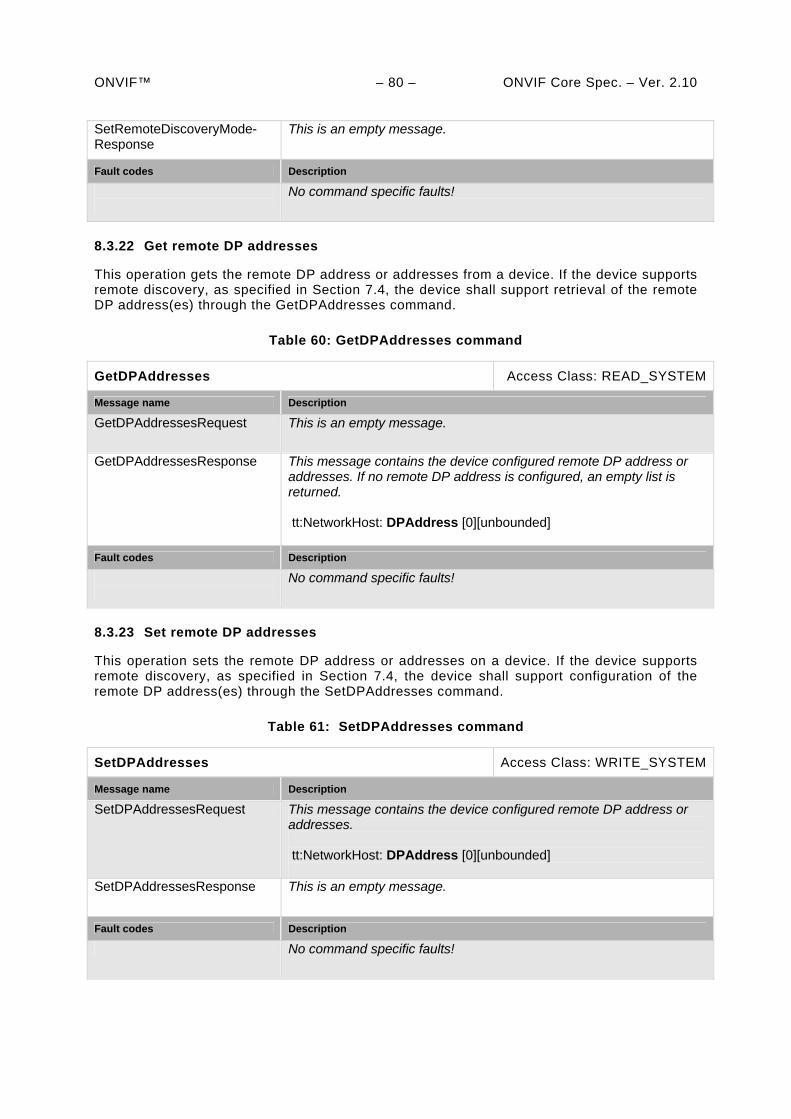
ONVIF™ – 80 – ONVIF Core Spec. – Ver. 2.10 SetRemoteDiscoveryMode-Response
This is an empty message.
Fault codes Description
No command specific faults!
8.3.22 Get remote DP addresses
This operation gets the remote DP address or addresses from a device. If the device supports remote discovery, as specified in Section 7.4, the device shall support retrieval of the remote DP address(es) through the GetDPAddresses command.
Table 60: GetDPAddresses command
GetDPAddresses Access Class: READ_SYSTEM
Message name Description
GetDPAddressesRequest This is an empty message.
GetDPAddressesResponse This message contains the device configured remote DP address or addresses. If no remote DP address is configured, an empty list is returned. tt:NetworkHost: DPAddress [0][unbounded]
Fault codes Description
No command specific faults!
8.3.23 Set remote DP addresses
This operation sets the remote DP address or addresses on a device. If the device supports remote discovery, as specified in Section 7.4, the device shall support configuration of the remote DP address(es) through the SetDPAddresses command.
Table 61: SetDPAddresses command
SetDPAddresses Access Class: WRITE_SYSTEM
Message name Description
SetDPAddressesRequest This message contains the device configured remote DP address or addresses. tt:NetworkHost: DPAddress [0][unbounded]
SetDPAddressesResponse This is an empty message.
Fault codes Description
No command specific faults!
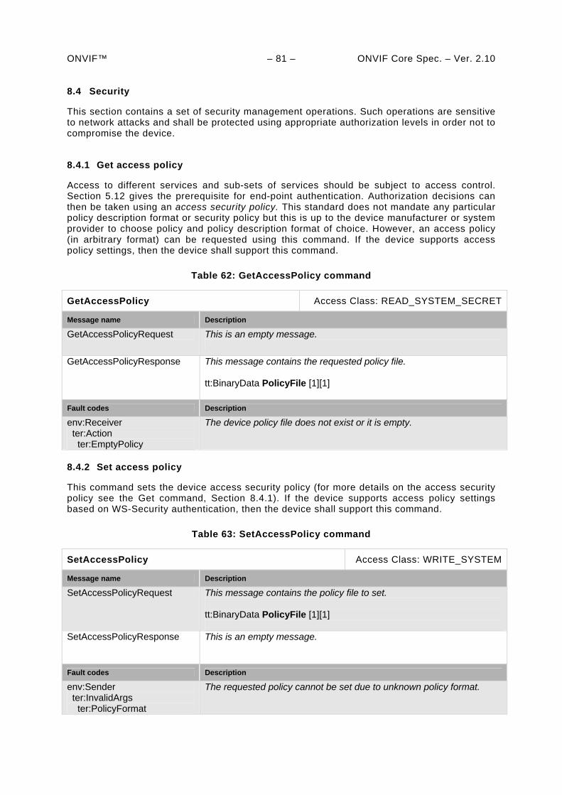
ONVIF™ – 81 – ONVIF Core Spec. – Ver. 2.10 8.4 Security
This section contains a set of security management operations. Such operations are sensitive to network attacks and shall be protected using appropriate authorization levels in order not to compromise the device.
8.4.1 Get access policy
Access to different services and sub-sets of services should be subject to access control. Section 5.12 gives the prerequisite for end-point authentication. Authorization decisions can then be taken using an access security policy. This standard does not mandate any particular policy description format or security policy but this is up to the device manufacturer or system provider to choose policy and policy description format of choice. However, an access policy (in arbitrary format) can be requested using this command. If the device supports access policy settings, then the device shall support this command.
Table 62: GetAccessPolicy command
GetAccessPolicy Access Class: READ_SYSTEM_SECRET
Message name Description
GetAccessPolicyRequest This is an empty message.
GetAccessPolicyResponse
This message contains the requested policy file. tt:BinaryData PolicyFile [1][1]
Fault codes Description
env:Receiver ter:Action ter:EmptyPolicy
The device policy file does not exist or it is empty.
8.4.2 Set access policy
This command sets the device access security policy (for more details on the access security policy see the Get command, Section 8.4.1). If the device supports access policy settings based on WS-Security authentication, then the device shall support this command.
Table 63: SetAccessPolicy command
SetAccessPolicy Access Class: WRITE_SYSTEM
Message name Description
SetAccessPolicyRequest This message contains the policy file to set. tt:BinaryData PolicyFile [1][1]
SetAccessPolicyResponse
This is an empty message.
Fault codes Description
env:Sender ter:InvalidArgs ter:PolicyFormat
The requested policy cannot be set due to unknown policy format.
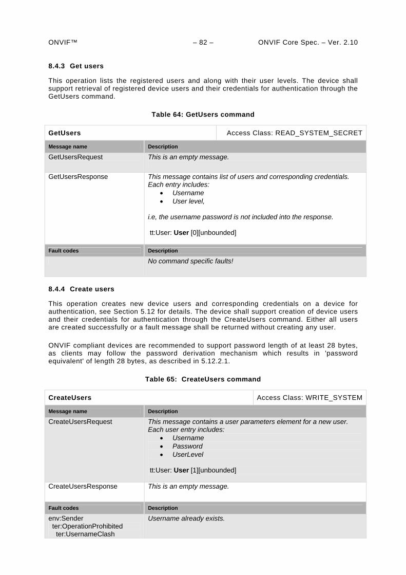
ONVIF™ – 82 – ONVIF Core Spec. – Ver. 2.10 8.4.3 Get users
This operation lists the registered users and along with their user levels. The device shall support retrieval of registered device users and their credentials for authentication through the GetUsers command.
Table 64: GetUsers command
GetUsers Access Class: READ_SYSTEM_SECRET
Message name Description
GetUsersRequest This is an empty message.
GetUsersResponse This message contains list of users and corresponding credentials. Each entry includes:
Username User level,
i.e, the username password is not included into the response. tt:User: User [0][unbounded]
Fault codes Description
No command specific faults!
8.4.4 Create users
This operation creates new device users and corresponding credentials on a device for authentication, see Section 5.12 for details. The device shall support creation of device users and their credentials for authentication through the CreateUsers command. Either all users are created successfully or a fault message shall be returned without creating any user.
ONVIF compliant devices are recommended to support password length of at least 28 bytes, as clients may follow the password derivation mechanism which results in 'password equivalent' of length 28 bytes, as described in 5.12.2.1.
Table 65: CreateUsers command
CreateUsers Access Class: WRITE_SYSTEM
Message name Description
CreateUsersRequest This message contains a user parameters element for a new user. Each user entry includes:
Username Password UserLevel
tt:User: User [1][unbounded]
CreateUsersResponse This is an empty message.
Fault codes Description
env:Sender ter:OperationProhibited ter:UsernameClash
Username already exists.
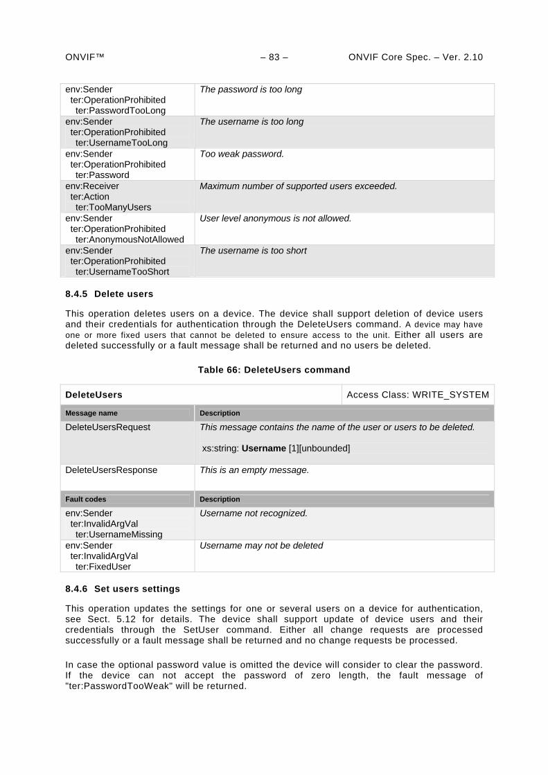
ONVIF™ – 83 – ONVIF Core Spec. – Ver. 2.10 env:Sender ter:OperationProhibited ter:PasswordTooLong
The password is too long
env:Sender ter:OperationProhibited ter:UsernameTooLong
The username is too long
env:Sender ter:OperationProhibited ter:Password
Too weak password.
env:Receiver ter:Action ter:TooManyUsers
Maximum number of supported users exceeded.
env:Sender ter:OperationProhibited ter:AnonymousNotAllowed
User level anonymous is not allowed.
env:Sender ter:OperationProhibited ter:UsernameTooShort
The username is too short
8.4.5 Delete users
This operation deletes users on a device. The device shall support deletion of device users and their credentials for authentication through the DeleteUsers command. A device may have one or more fixed users that cannot be deleted to ensure access to the unit. Either all users are deleted successfully or a fault message shall be returned and no users be deleted.
Table 66: DeleteUsers command
DeleteUsers Access Class: WRITE_SYSTEM
Message name Description
DeleteUsersRequest This message contains the name of the user or users to be deleted. xs:string: Username [1][unbounded]
DeleteUsersResponse This is an empty message.
Fault codes Description
env:Sender ter:InvalidArgVal ter:UsernameMissing
Username not recognized.
env:Sender ter:InvalidArgVal ter:FixedUser
Username may not be deleted
8.4.6 Set users settings
This operation updates the settings for one or several users on a device for authentication, see Sect. 5.12 for details. The device shall support update of device users and their credentials through the SetUser command. Either all change requests are processed successfully or a fault message shall be returned and no change requests be processed.
In case the optional password value is omitted the device will consider to clear the password. If the device can not accept the password of zero length, the fault message of "ter:PasswordTooWeak" will be returned.
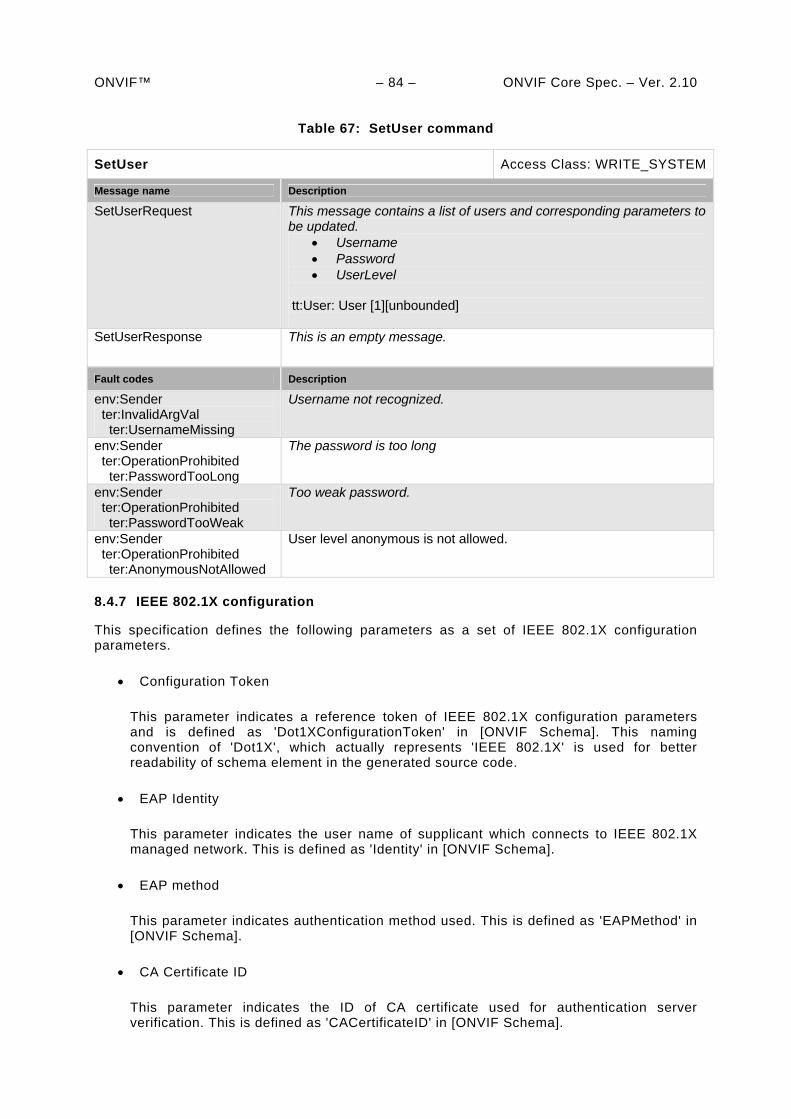
ONVIF™ – 84 – ONVIF Core Spec. – Ver. 2.10
Table 67: SetUser command
SetUser Access Class: WRITE_SYSTEM
Message name Description
SetUserRequest This message contains a list of users and corresponding parameters to be updated.
Username Password UserLevel
tt:User: User [1][unbounded]
SetUserResponse This is an empty message.
Fault codes Description
env:Sender ter:InvalidArgVal ter:UsernameMissing
Username not recognized.
env:Sender ter:OperationProhibited ter:PasswordTooLong
The password is too long
env:Sender ter:OperationProhibited ter:PasswordTooWeak
Too weak password.
env:Sender ter:OperationProhibited ter:AnonymousNotAllowed
User level anonymous is not allowed.
8.4.7 IEEE 802.1X configuration
This specification defines the following parameters as a set of IEEE 802.1X configuration parameters.
Configuration Token
This parameter indicates a reference token of IEEE 802.1X configuration parameters and is defined as 'Dot1XConfigurationToken' in [ONVIF Schema]. This naming convention of 'Dot1X', which actually represents 'IEEE 802.1X' is used for better readability of schema element in the generated source code.
EAP Identity
This parameter indicates the user name of supplicant which connects to IEEE 802.1X managed network. This is defined as 'Identity' in [ONVIF Schema].
EAP method
This parameter indicates authentication method used. This is defined as 'EAPMethod' in [ONVIF Schema].
CA Certificate ID
This parameter indicates the ID of CA certificate used for authentication server verification. This is defined as 'CACertificateID' in [ONVIF Schema].
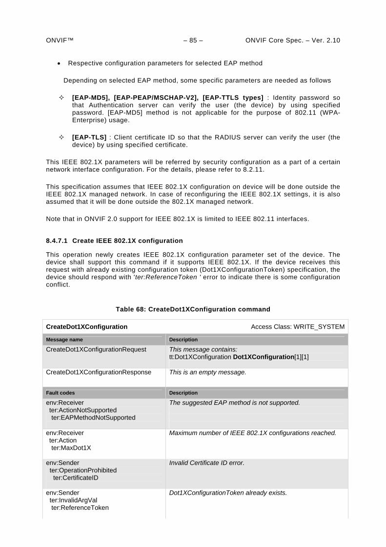
ONVIF™ – 85 – ONVIF Core Spec. – Ver. 2.10
Respective configuration parameters for selected EAP method
Depending on selected EAP method, some specific parameters are needed as follows
[EAP-MD5], [EAP-PEAP/MSCHAP-V2], [EAP-TTLS types] : Identity password so that Authentication server can verify the user (the device) by using specified password. [EAP-MD5] method is not applicable for the purpose of 802.11 (WPA-Enterprise) usage.
[EAP-TLS] : Client certificate ID so that the RADIUS server can verify the user (the device) by using specified certificate.
This IEEE 802.1X parameters will be referred by security configuration as a part of a certain network interface configuration. For the details, please refer to 8.2.11.
This specification assumes that IEEE 802.1X configuration on device will be done outside the IEEE 802.1X managed network. In case of reconfiguring the IEEE 802.1X settings, it is also assumed that it will be done outside the 802.1X managed network.
Note that in ONVIF 2.0 support for IEEE 802.1X is limited to IEEE 802.11 interfaces.
8.4.7.1 Create IEEE 802.1X configuration
This operation newly creates IEEE 802.1X configuration parameter set of the device. The device shall support this command if it supports IEEE 802.1X. If the device receives this request with already existing configuration token (Dot1XConfigurationToken) specification, the device should respond with 'ter:ReferenceToken ' error to indicate there is some configuration conflict.
Table 68: CreateDot1XConfiguration command
CreateDot1XConfiguration Access Class: WRITE_SYSTEM
Message name Description
CreateDot1XConfigurationRequest This message contains: tt:Dot1XConfiguration Dot1XConfiguration[1][1]
CreateDot1XConfigurationResponse This is an empty message.
Fault codes Description
env:Receiver ter:ActionNotSupported
ter:EAPMethodNotSupported
The suggested EAP method is not supported.
env:Receiver ter:Action
ter:MaxDot1X
Maximum number of IEEE 802.1X configurations reached.
env:Sender ter:OperationProhibited ter:CertificateID
Invalid Certificate ID error.
env:Sender ter:InvalidArgVal ter:ReferenceToken
Dot1XConfigurationToken already exists.
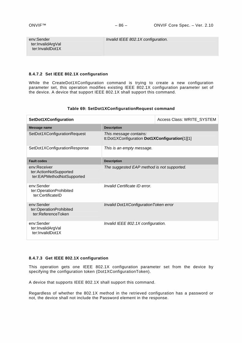
ONVIF™ – 86 – ONVIF Core Spec. – Ver. 2.10 env:Sender ter:InvalidArgVal ter:InvalidDot1X
Invalid IEEE 802.1X configuration.
8.4.7.2 Set IEEE 802.1X configuration
While the CreateDot1XConfiguration command is trying to create a new configuration parameter set, this operation modifies existing IEEE 802.1X configuration parameter set of the device. A device that support IEEE 802.1X shall support this command.
Table 69: SetDot1XConfigurationRequest command
SetDot1XConfiguration Access Class: WRITE_SYSTEM
Message name Description
SetDot1XConfigurationRequest This message contains: tt:Dot1XConfiguration Dot1XConfiguration[1][1]
SetDot1XConfigurationResponse This is an empty message.
Fault codes Description
env:Receiver ter:ActionNotSupported
ter:EAPMethodNotSupported
The suggested EAP method is not supported.
env:Sender ter:OperationProhibited ter:CertificateID
Invalid Certificate ID error.
env:Sender ter:OperationProhibited ter:ReferenceToken
Invalid Dot1XConfigurationToken error
env:Sender ter:InvalidArgVal ter:InvalidDot1X
Invalid IEEE 802.1X configuration.
8.4.7.3 Get IEEE 802.1X configuration
This operation gets one IEEE 802.1X configuration parameter set from the device by specifying the configuration token (Dot1XConfigurationToken).
A device that supports IEEE 802.1X shall support this command.
Regardless of whether the 802.1X method in the retrieved configuration has a password or not, the device shall not include the Password element in the response.
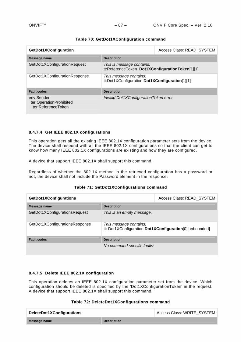
ONVIF™ – 87 – ONVIF Core Spec. – Ver. 2.10
Table 70: GetDot1XConfiguration command
GetDot1XConfiguration Access Class: READ_SYSTEM
Message name Description
GetDot1XConfigurationRequest This is message contains: tt:ReferenceToken Dot1XConfigurationToken[1][1]
GetDot1XConfigurationResponse This message contains: tt:Dot1XConfiguration Dot1XConfiguration[1][1]
Fault codes Description
env:Sender ter:OperationProhibited ter:ReferenceToken
Invalid Dot1XConfigurationToken error
8.4.7.4 Get IEEE 802.1X configurations
This operation gets all the existing IEEE 802.1X configuration parameter sets from the device. The device shall respond with all the IEEE 802.1X configurations so that the client can get to know how many IEEE 802.1X configurations are existing and how they are configured.
A device that support IEEE 802.1X shall support this command.
Regardless of whether the 802.1X method in the retrieved configuration has a password or not, the device shall not include the Password element in the response.
Table 71: GetDot1XConfigurations command
GetDot1XConfigurations Access Class: READ_SYSTEM
Message name Description
GetDot1XConfigurationsRequest This is an empty message.
GetDot1XConfigurationsResponse This message contains: tt: Dot1XConfiguration Dot1XConfiguration[0][unbounded]
Fault codes Description
No command specific faults!
8.4.7.5 Delete IEEE 802.1X configuration
This operation deletes an IEEE 802.1X configuration parameter set from the device. Which configuration should be deleted is specified by the 'Dot1XConfigurationToken' in the request. A device that support IEEE 802.1X shall support this command.
Table 72: DeleteDot1XConfigurations command
DeleteDot1XConfigurations Access Class: WRITE_SYSTEM
Message name Description
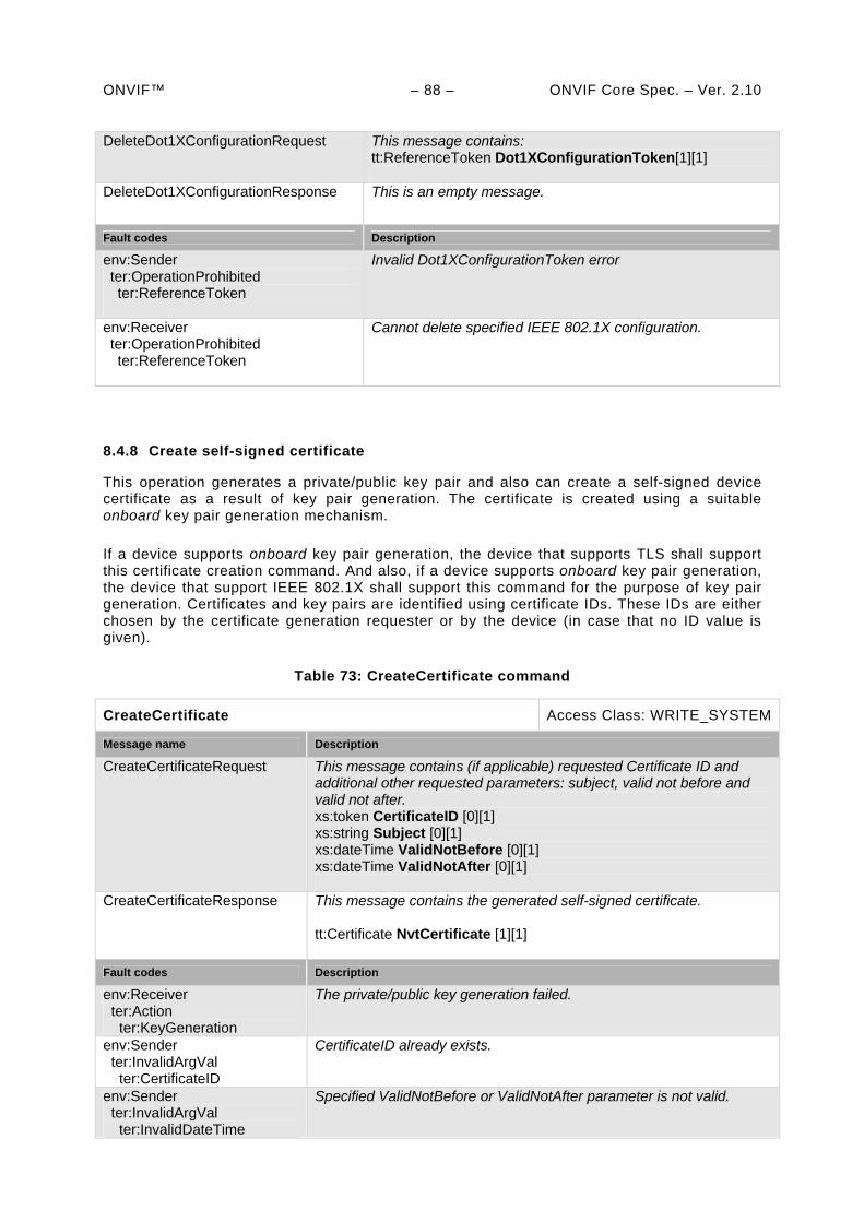
ONVIF™ – 88 – ONVIF Core Spec. – Ver. 2.10 DeleteDot1XConfigurationRequest This message contains:
tt:ReferenceToken Dot1XConfigurationToken[1][1]
DeleteDot1XConfigurationResponse This is an empty message.
Fault codes Description
env:Sender ter:OperationProhibited ter:ReferenceToken
Invalid Dot1XConfigurationToken error
env:Receiver ter:OperationProhibited ter:ReferenceToken
Cannot delete specified IEEE 802.1X configuration.
8.4.8 Create self-signed certificate
This operation generates a private/public key pair and also can create a self-signed device certificate as a result of key pair generation. The certificate is created using a suitable onboard key pair generation mechanism.
If a device supports onboard key pair generation, the device that supports TLS shall support this certificate creation command. And also, if a device supports onboard key pair generation, the device that support IEEE 802.1X shall support this command for the purpose of key pair generation. Certificates and key pairs are identified using certificate IDs. These IDs are either chosen by the certificate generation requester or by the device (in case that no ID value is given).
Table 73: CreateCertificate command
CreateCertificate Access Class: WRITE_SYSTEM
Message name Description
CreateCertificateRequest This message contains (if applicable) requested Certificate ID and additional other requested parameters: subject, valid not before and valid not after. xs:token CertificateID [0][1] xs:string Subject [0][1] xs:dateTime ValidNotBefore [0][1] xs:dateTime ValidNotAfter [0][1]
CreateCertificateResponse
This message contains the generated self-signed certificate. tt:Certificate NvtCertificate [1][1]
Fault codes Description
env:Receiver ter:Action ter:KeyGeneration
The private/public key generation failed.
env:Sender ter:InvalidArgVal ter:CertificateID
CertificateID already exists.
env:Sender ter:InvalidArgVal ter:InvalidDateTime
Specified ValidNotBefore or ValidNotAfter parameter is not valid.
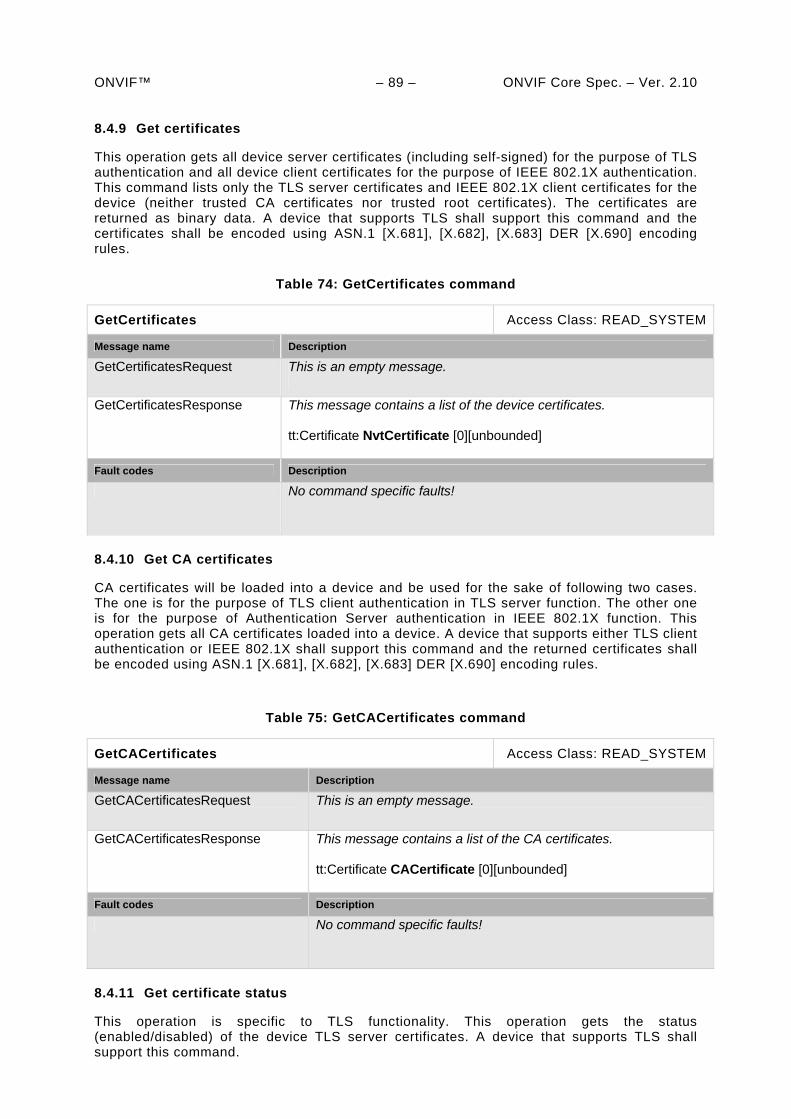
ONVIF™ – 89 – ONVIF Core Spec. – Ver. 2.10 8.4.9 Get certificates
This operation gets all device server certificates (including self-signed) for the purpose of TLS authentication and all device client certificates for the purpose of IEEE 802.1X authentication. This command lists only the TLS server certificates and IEEE 802.1X client certificates for the device (neither trusted CA certificates nor trusted root certificates). The certificates are returned as binary data. A device that supports TLS shall support this command and the certificates shall be encoded using ASN.1 [X.681], [X.682], [X.683] DER [X.690] encoding rules.
Table 74: GetCertificates command
GetCertificates Access Class: READ_SYSTEM
Message name Description
GetCertificatesRequest This is an empty message.
GetCertificatesResponse
This message contains a list of the device certificates. tt:Certificate NvtCertificate [0][unbounded]
Fault codes Description
No command specific faults!
8.4.10 Get CA certificates
CA certificates will be loaded into a device and be used for the sake of following two cases. The one is for the purpose of TLS client authentication in TLS server function. The other one is for the purpose of Authentication Server authentication in IEEE 802.1X function. This operation gets all CA certificates loaded into a device. A device that supports either TLS client authentication or IEEE 802.1X shall support this command and the returned certificates shall be encoded using ASN.1 [X.681], [X.682], [X.683] DER [X.690] encoding rules.
Table 75: GetCACertificates command
GetCACertificates Access Class: READ_SYSTEM
Message name Description
GetCACertificatesRequest This is an empty message.
GetCACertificatesResponse
This message contains a list of the CA certificates. tt:Certificate CACertificate [0][unbounded]
Fault codes Description
No command specific faults!
8.4.11 Get certificate status
This operation is specific to TLS functionality. This operation gets the status (enabled/disabled) of the device TLS server certificates. A device that supports TLS shall support this command.
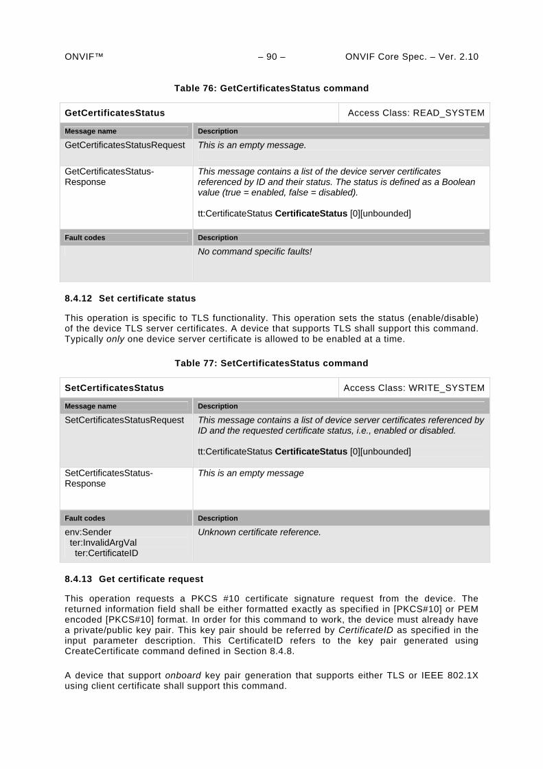
ONVIF™ – 90 – ONVIF Core Spec. – Ver. 2.10
Table 76: GetCertificatesStatus command
GetCertificatesStatus Access Class: READ_SYSTEM
Message name Description
GetCertificatesStatusRequest This is an empty message.
GetCertificatesStatus-Response
This message contains a list of the device server certificates referenced by ID and their status. The status is defined as a Boolean value (true = enabled, false = disabled). tt:CertificateStatus CertificateStatus [0][unbounded]
Fault codes Description
No command specific faults!
8.4.12 Set certificate status
This operation is specific to TLS functionality. This operation sets the status (enable/disable) of the device TLS server certificates. A device that supports TLS shall support this command. Typically only one device server certificate is allowed to be enabled at a time.
Table 77: SetCertificatesStatus command
SetCertificatesStatus Access Class: WRITE_SYSTEM
Message name Description
SetCertificatesStatusRequest This message contains a list of device server certificates referenced by ID and the requested certificate status, i.e., enabled or disabled. tt:CertificateStatus CertificateStatus [0][unbounded]
SetCertificatesStatus-Response
This is an empty message
Fault codes Description
env:Sender ter:InvalidArgVal ter:CertificateID
Unknown certificate reference.
8.4.13 Get certificate request
This operation requests a PKCS #10 certificate signature request from the device. The returned information field shall be either formatted exactly as specified in [PKCS#10] or PEM encoded [PKCS#10] format. In order for this command to work, the device must already have a private/public key pair. This key pair should be referred by CertificateID as specified in the input parameter description. This CertificateID refers to the key pair generated using CreateCertificate command defined in Section 8.4.8.
A device that support onboard key pair generation that supports either TLS or IEEE 802.1X using client certificate shall support this command.
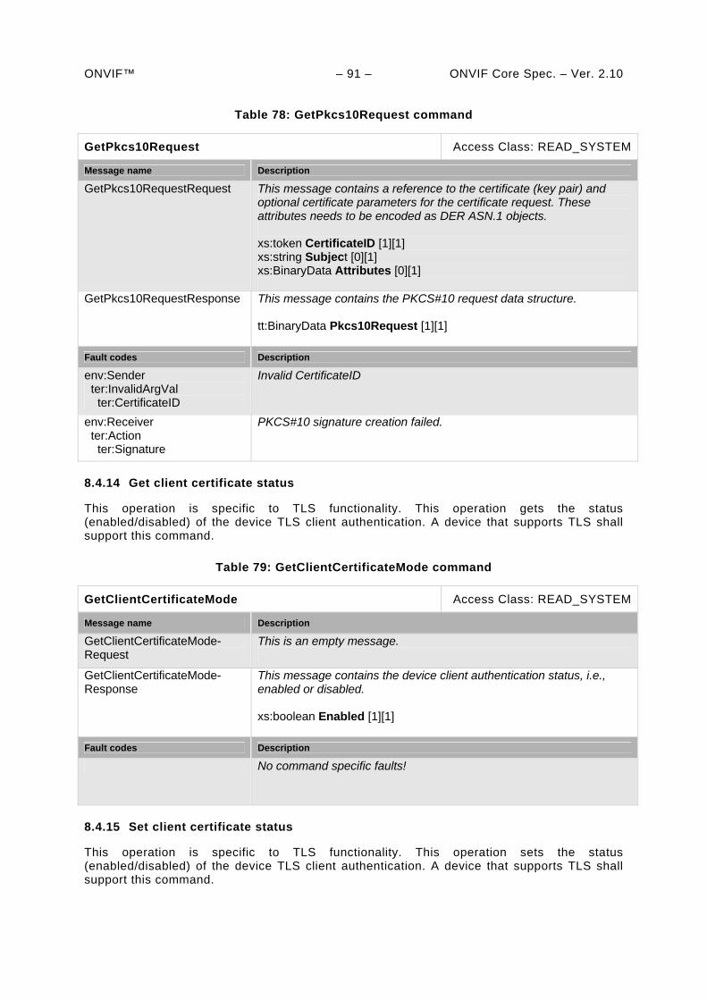
ONVIF™ – 91 – ONVIF Core Spec. – Ver. 2.10
Table 78: GetPkcs10Request command
GetPkcs10Request Access Class: READ_SYSTEM
Message name Description
GetPkcs10RequestRequest This message contains a reference to the certificate (key pair) and optional certificate parameters for the certificate request. These attributes needs to be encoded as DER ASN.1 objects. xs:token CertificateID [1][1] xs:string Subject [0][1] xs:BinaryData Attributes [0][1]
GetPkcs10RequestResponse
This message contains the PKCS#10 request data structure. tt:BinaryData Pkcs10Request [1][1]
Fault codes Description
env:Sender ter:InvalidArgVal ter:CertificateID
Invalid CertificateID
env:Receiver ter:Action ter:Signature
PKCS#10 signature creation failed.
8.4.14 Get client certificate status
This operation is specific to TLS functionality. This operation gets the status (enabled/disabled) of the device TLS client authentication. A device that supports TLS shall support this command.
Table 79: GetClientCertificateMode command
GetClientCertificateMode Access Class: READ_SYSTEM
Message name Description
GetClientCertificateMode-Request
This is an empty message.
GetClientCertificateMode-Response
This message contains the device client authentication status, i.e., enabled or disabled. xs:boolean Enabled [1][1]
Fault codes Description
No command specific faults!
8.4.15 Set client certificate status
This operation is specific to TLS functionality. This operation sets the status (enabled/disabled) of the device TLS client authentication. A device that supports TLS shall support this command.
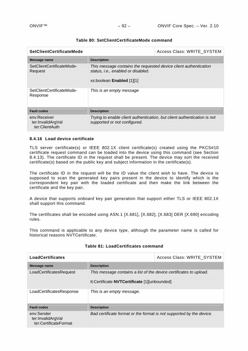
ONVIF™ – 92 – ONVIF Core Spec. – Ver. 2.10
Table 80: SetClientCertificateMode command
SetClientCertificateMode Access Class: WRITE_SYSTEM
Message name Description
SetClientCertificateMode-Request
This message contains the requested device client authentication status, i.e., enabled or disabled. xs:boolean Enabled [1][1]
SetClientCertificateMode-Response
This is an empty message
Fault codes Description
env:Receiver ter:InvalidArgVal ter:ClientAuth
Trying to enable client authentication, but client authentication is not supported or not configured.
8.4.16 Load device certificate
TLS server certificate(s) or IEEE 802.1X client certificate(s) created using the PKCS#10 certificate request command can be loaded into the device using this command (see Section 8.4.13). The certificate ID in the request shall be present. The device may sort the received certificate(s) based on the public key and subject information in the certificate(s).
The certificate ID in the request will be the ID value the client wish to have. The device is supposed to scan the generated key pairs present in the device to identify which is the correspondent key pair with the loaded certificate and then make the link between the certificate and the key pair.
A device that supports onboard key pair generation that support either TLS or IEEE 802.1X shall support this command.
The certificates shall be encoded using ASN.1 [X.681], [X.682], [X.683] DER [X.690] encoding rules.
This command is applicable to any device type, although the parameter name is called for historical reasons NVTCertificate.
Table 81: LoadCertificates command
LoadCertificates Access Class: WRITE_SYSTEM
Message name Description
LoadCertificatesRequest This message contains a list of the device certificates to upload. tt:Certificate NVTCertificate [1][unbounded]
LoadCertificatesResponse
This is an empty message.
Fault codes Description
env:Sender ter:InvalidArgVal ter:CertificateFormat
Bad certificate format or the format is not supported by the device.
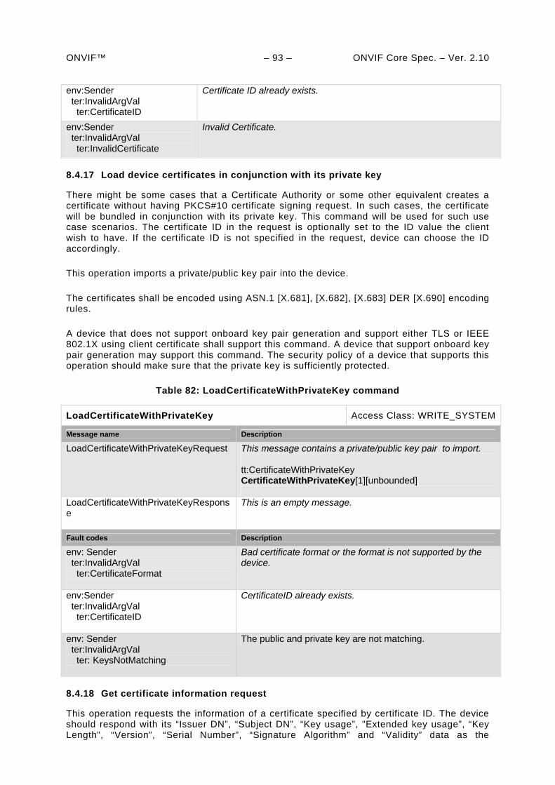
ONVIF™ – 93 – ONVIF Core Spec. – Ver. 2.10 env:Sender ter:InvalidArgVal ter:CertificateID
Certificate ID already exists.
env:Sender ter:InvalidArgVal ter:InvalidCertificate
Invalid Certificate.
8.4.17 Load device certificates in conjunction with its private key
There might be some cases that a Certificate Authority or some other equivalent creates a certificate without having PKCS#10 certificate signing request. In such cases, the certificate will be bundled in conjunction with its private key. This command will be used for such use case scenarios. The certificate ID in the request is optionally set to the ID value the client wish to have. If the certificate ID is not specified in the request, device can choose the ID accordingly.
This operation imports a private/public key pair into the device.
The certificates shall be encoded using ASN.1 [X.681], [X.682], [X.683] DER [X.690] encoding rules.
A device that does not support onboard key pair generation and support either TLS or IEEE 802.1X using client certificate shall support this command. A device that support onboard key pair generation may support this command. The security policy of a device that supports this operation should make sure that the private key is sufficiently protected.
Table 82: LoadCertificateWithPrivateKey command
LoadCertificateWithPrivateKey Access Class: WRITE_SYSTEM
Message name Description
LoadCertificateWithPrivateKeyRequest This message contains a private/public key pair to import. tt:CertificateWithPrivateKey CertificateWithPrivateKey[1][unbounded]
LoadCertificateWithPrivateKeyResponse
This is an empty message.
Fault codes Description
env: Sender ter:InvalidArgVal ter:CertificateFormat
Bad certificate format or the format is not supported by the device.
env:Sender ter:InvalidArgVal ter:CertificateID
CertificateID already exists.
env: Sender ter:InvalidArgVal ter: KeysNotMatching
The public and private key are not matching.
8.4.18 Get certificate information request
This operation requests the information of a certificate specified by certificate ID. The device should respond with its “Issuer DN”, “Subject DN”, “Key usage”, "Extended key usage”, “Key Length”, “Version”, “Serial Number”, “Signature Algorithm” and “Validity” data as the
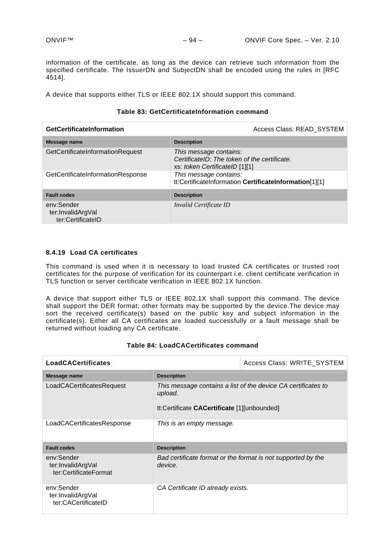
ONVIF™ – 94 – ONVIF Core Spec. – Ver. 2.10 information of the certificate, as long as the device can retrieve such information from the specified certificate. The IssuerDN and SubjectDN shall be encoded using the rules in [RFC 4514].
A device that supports either TLS or IEEE 802.1X should support this command.
Table 83: GetCertificateInformation command
GetCertificateInformation Access Class: READ_SYSTEM
Message name Description
GetCertificateInformationRequest This message contains: CertificateID: The token of the certificate. xs: token CertificateID [1][1]
GetCertificateInformationResponse This message contains: tt:CertificateInformation CertificateInformation[1][1]
Fault codes Description
env:Sender ter:InvalidArgVal ter:CertificateID
Invalid Certificate ID
8.4.19 Load CA certificates
This command is used when it is necessary to load trusted CA certificates or trusted root certificates for the purpose of verification for its counterpart i.e. client certificate verification in TLS function or server certificate verification in IEEE 802.1X function.
A device that support either TLS or IEEE 802.1X shall support this command. The device shall support the DER format; other formats may be supported by the device.The device may sort the received certificate(s) based on the public key and subject information in the certificate(s). Either all CA certificates are loaded successfully or a fault message shall be returned without loading any CA certificate.
Table 84: LoadCACertificates command
LoadCACertificates Access Class: WRITE_SYSTEM
Message name Description
LoadCACertificatesRequest This message contains a list of the device CA certificates to upload. tt:Certificate CACertificate [1][unbounded]
LoadCACertificatesResponse
This is an empty message.
Fault codes Description
env:Sender ter:InvalidArgVal ter:CertificateFormat
Bad certificate format or the format is not supported by the device.
env:Sender ter:InvalidArgVal ter:CACertificateID
CA Certificate ID already exists.
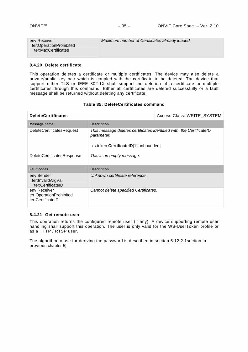
ONVIF™ – 95 – ONVIF Core Spec. – Ver. 2.10 env:Receiver ter:OperationProhibited ter:MaxCertificates
Maximum number of Certificates already loaded.
8.4.20 Delete certificate
This operation deletes a certificate or multiple certificates. The device may also delete a private/public key pair which is coupled with the certificate to be deleted. The device that support either TLS or IEEE 802.1X shall support the deletion of a certificate or multiple certificates through this command. Either all certificates are deleted successfully or a fault message shall be returned without deleting any certificate.
Table 85: DeleteCertificates command
DeleteCertificates Access Class: WRITE_SYSTEM
Message name Description
DeleteCertificatesRequest This message deletes certificates identified with the CertificateID parameter. xs:token CertificateID[1][unbounded]
DeleteCertificatesResponse This is an empty message.
Fault codes Description
env:Sender ter:InvalidArgVal ter:CertificateID
Unknown certificate reference.
env:Receiver ter:OperationProhibited ter:CertificateID
Cannot delete specified Certificates.
8.4.21 Get remote user
This operation returns the configured remote user (if any). A device supporting remote user handling shall support this operation. The user is only valid for the WS-UserToken profile or as a HTTP / RTSP user. The algorithm to use for deriving the password is described in section 5.12.2.1section in previous chapter 5].
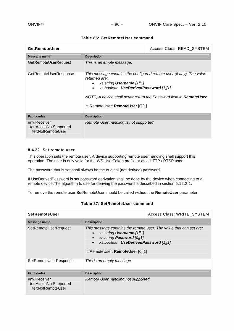
ONVIF™ – 96 – ONVIF Core Spec. – Ver. 2.10
Table 86: GetRemoteUser command
GetRemoteUser Access Class: READ_SYSTEM
Message name Description
GetRemoteUserRequest This is an empty message.
GetRemoteUserResponse This message contains the configured remote user (if any). The value returned are:
xs:string Username [1][1] xs:boolean UseDerivedPassword [1][1]
NOTE; A device shall never return the Password field in RemoteUser. tt:RemoteUser: RemoteUser [0][1]
Fault codes Description
env:Receiver ter:ActionNotSupported ter:NotRemoteUser
Remote User handling is not supported
8.4.22 Set remote user
This operation sets the remote user. A device supporting remote user handling shall support this operation. The user is only valid for the WS-UserToken profile or as a HTTP / RTSP user. The password that is set shall always be the original (not derived) password. If UseDerivedPassword is set password derivation shall be done by the device when connecting to a remote device.The algorithm to use for deriving the password is described in section 5.12.2.1. To remove the remote user SetRemoteUser should be called without the RemoteUser parameter.
Table 87: SetRemoteUser command
SetRemoteUser Access Class: WRITE_SYSTEM
Message name Description
SetRemoteUserRequest This message contains the remote user. The value that can set are: xs:string Username [1][1] xs:string Password [0][1] xs:boolean UseDerivedPassword [1][1]
tt:RemoteUser: RemoteUser [0][1]
SetRemoteUserResponse This is an empty message
Fault codes Description
env:Receiver ter:ActionNotSupported ter:NotRemoteUser
Remote User handling not supported
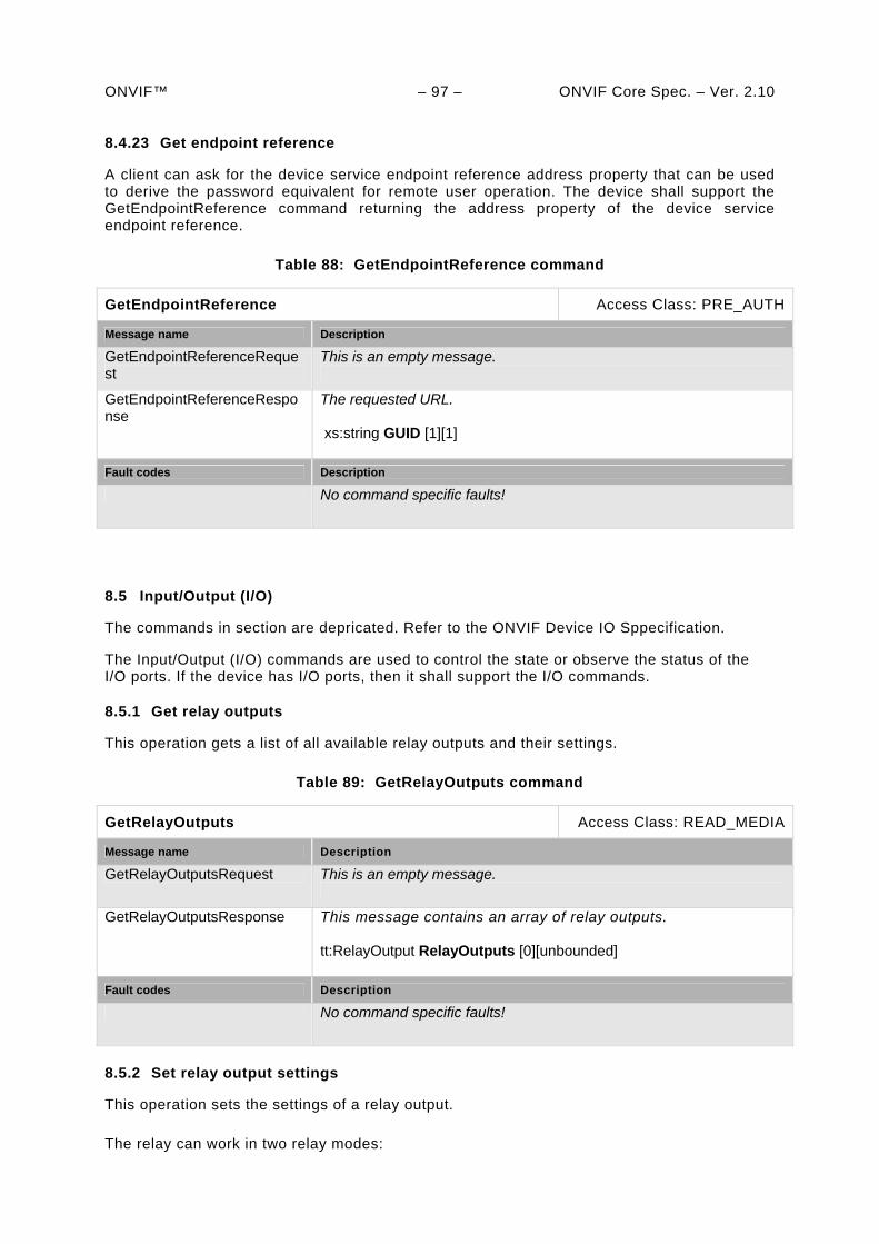
ONVIF™ – 97 – ONVIF Core Spec. – Ver. 2.10 8.4.23 Get endpoint reference
A client can ask for the device service endpoint reference address property that can be used to derive the password equivalent for remote user operation. The device shall support the GetEndpointReference command returning the address property of the device service endpoint reference.
Table 88: GetEndpointReference command
GetEndpointReference Access Class: PRE_AUTH
Message name Description
GetEndpointReferenceRequest
This is an empty message.
GetEndpointReferenceResponse
The requested URL. xs:string GUID [1][1]
Fault codes Description
No command specific faults!
8.5 Input/Output (I/O)
The commands in section are depricated. Refer to the ONVIF Device IO Sppecification.
The Input/Output (I/O) commands are used to control the state or observe the status of the I/O ports. If the device has I/O ports, then it shall support the I/O commands.
8.5.1 Get relay outputs
This operation gets a list of all available relay outputs and their settings.
Table 89: GetRelayOutputs command
GetRelayOutputs Access Class: READ_MEDIA
Message name Description
GetRelayOutputsRequest This is an empty message.
GetRelayOutputsResponse This message contains an array of relay outputs. tt:RelayOutput RelayOutputs [0][unbounded]
Fault codes Description
No command specific faults!
8.5.2 Set relay output settings
This operation sets the settings of a relay output.
The relay can work in two relay modes:
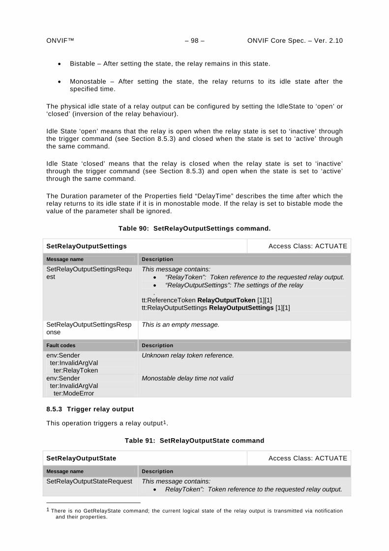
ONVIF™ – 98 – ONVIF Core Spec. – Ver. 2.10
Bistable – After setting the state, the relay remains in this state.
Monostable – After setting the state, the relay returns to its idle state after the specified time.
The physical idle state of a relay output can be configured by setting the IdleState to ‘open’ or ‘closed’ (inversion of the relay behaviour).
Idle State ‘open’ means that the relay is open when the relay state is set to ‘inactive’ through the trigger command (see Section 8.5.3) and closed when the state is set to ‘active’ through the same command.
Idle State ‘closed’ means that the relay is closed when the relay state is set to ‘inactive’ through the trigger command (see Section 8.5.3) and open when the state is set to ‘active’ through the same command.
The Duration parameter of the Properties field “DelayTime” describes the time after which the relay returns to its idle state if it is in monostable mode. If the relay is set to bistable mode the value of the parameter shall be ignored.
Table 90: SetRelayOutputSettings command.
SetRelayOutputSettings Access Class: ACTUATE
Message name Description
SetRelayOutputSettingsRequest
This message contains: “RelayToken”: Token reference to the requested relay output. “RelayOutputSettings”: The settings of the relay .
tt:ReferenceToken RelayOutputToken [1][1] tt:RelayOutputSettings RelayOutputSettings [1][1]
SetRelayOutputSettingsResponse
This is an empty message.
Fault codes Description
env:Sender ter:InvalidArgVal ter:RelayToken
Unknown relay token reference.
env:Sender ter:InvalidArgVal ter:ModeError
Monostable delay time not valid
8.5.3 Trigger relay output
This operation triggers a relay output1.
Table 91: SetRelayOutputState command
SetRelayOutputState Access Class: ACTUATE
Message name Description
SetRelayOutputStateRequest This message contains: RelayToken”: Token reference to the requested relay output.
1 There is no GetRelayState command; the current logical state of the relay output is transmitted via notification
and their properties.
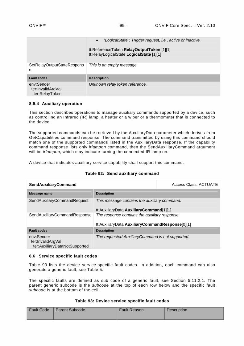
ONVIF™ – 99 – ONVIF Core Spec. – Ver. 2.10
“LogicalState”: Trigger request, i.e., active or inactive.
tt:ReferenceToken RelayOutputToken [1][1] tt:RelayLogicalState LogicalState [1][1]
SetRelayOutputStateResponse
This is an empty message.
Fault codes Description
env:Sender ter:InvalidArgVal ter:RelayToken
Unknown relay token reference.
8.5.4 Auxiliary operation
This section describes operations to manage auxiliary commands supported by a device, such as controlling an Infrared (IR) lamp, a heater or a wiper or a thermometer that is connected to the device.
The supported commands can be retrieved by the AuxiliaryData parameter which derives from GetCapabilities command response. The command transmitted by using this command should match one of the supported commands listed in the AuxiliaryData response. If the capability command response lists only irlampon command, then the SendAuxiliaryCommand argument will be irlampon, which may indicate turning the connected IR lamp on.
A device that indicates auxiliary service capability shall support this command.
Table 92: Send auxiliary command
SendAuxiliaryCommand Access Class: ACTUATE
Message name Description
SendAuxiliaryCommandRequest This message contains the auxiliary command. tt:AuxiliaryData AuxiliaryCommand[1][1]
SendAuxiliaryCommandResponse The response contains the auxiliary response. tt:AuxiliaryData AuxiliaryCommandResponse[0][1]
Fault codes Description
env:Sender ter:InvalidArgVal ter:AuxiliaryDataNotSupported
The requested AuxiliaryCommand is not supported.
8.6 Service specific fault codes
Table 93 lists the device service-specific fault codes. In addition, each command can also generate a generic fault, see Table 5.
The specific faults are defined as sub code of a generic fault, see Section 5.11.2.1. The parent generic subcode is the subcode at the top of each row below and the specific fault subcode is at the bottom of the cell.
Table 93: Device service specific fault codes
Fault Code Parent Subcode Fault Reason Description
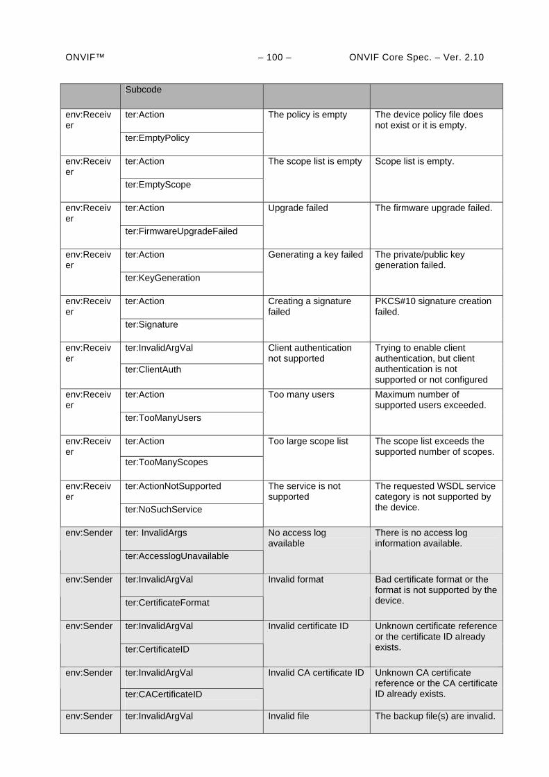
ONVIF™ – 100 – ONVIF Core Spec. – Ver. 2.10
Subcode
ter:Action env:Receiver
ter:EmptyPolicy
The policy is empty The device policy file does not exist or it is empty.
ter:Action env:Receiver
ter:EmptyScope
The scope list is empty Scope list is empty.
ter:Action env:Receiver
ter:FirmwareUpgradeFailed
Upgrade failed The firmware upgrade failed.
ter:Action env:Receiver ter:KeyGeneration
Generating a key failed The private/public key generation failed.
ter:Action env:Receiver
ter:Signature
Creating a signature failed
PKCS#10 signature creation failed.
ter:InvalidArgVal
env:Receiver
ter:ClientAuth
Client authentication not supported
Trying to enable client authentication, but client authentication is not supported or not configured
ter:Action env:Receiver ter:TooManyUsers
Too many users Maximum number of supported users exceeded.
ter:Action env:Receiver
ter:TooManyScopes
Too large scope list The scope list exceeds the supported number of scopes.
ter:ActionNotSupported env:Receiver
ter:NoSuchService
The service is not supported
The requested WSDL service category is not supported by the device.
ter: InvalidArgs env:Sender
ter:AccesslogUnavailable
No access log available
There is no access log information available.
ter:InvalidArgVal env:Sender
ter:CertificateFormat
Invalid format Bad certificate format or the format is not supported by the device.
ter:InvalidArgVal env:Sender
ter:CertificateID
Invalid certificate ID Unknown certificate reference or the certificate ID already exists.
ter:InvalidArgVal
env:Sender
ter:CACertificateID
Invalid CA certificate ID Unknown CA certificate reference or the CA certificate ID already exists.
env:Sender ter:InvalidArgVal Invalid file The backup file(s) are invalid.
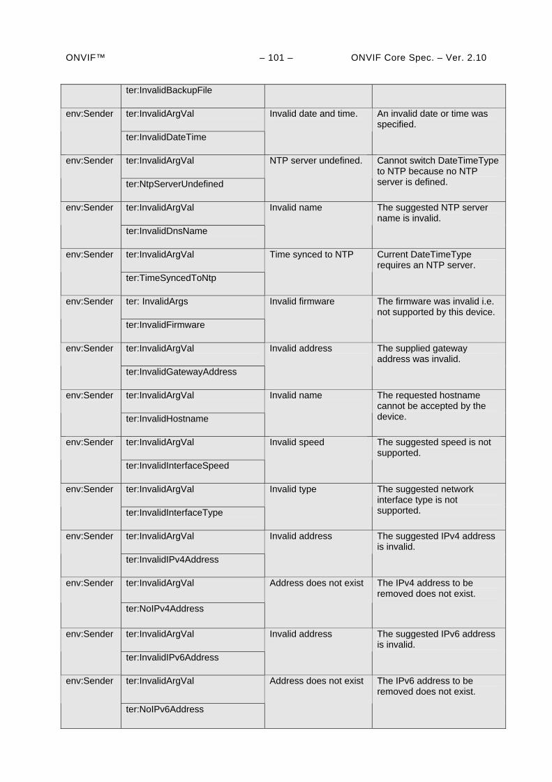
ONVIF™ – 101 – ONVIF Core Spec. – Ver. 2.10
ter:InvalidBackupFile
ter:InvalidArgVal env:Sender
ter:InvalidDateTime
Invalid date and time. An invalid date or time was specified.
ter:InvalidArgVal env:Sender
ter:NtpServerUndefined
NTP server undefined. Cannot switch DateTimeType to NTP because no NTP server is defined.
ter:InvalidArgVal env:Sender
ter:InvalidDnsName
Invalid name The suggested NTP server name is invalid.
ter:InvalidArgVal env:Sender
ter:TimeSyncedToNtp
Time synced to NTP Current DateTimeType requires an NTP server.
ter: InvalidArgs env:Sender
ter:InvalidFirmware
Invalid firmware The firmware was invalid i.e. not supported by this device.
ter:InvalidArgVal env:Sender
ter:InvalidGatewayAddress
Invalid address The supplied gateway address was invalid.
ter:InvalidArgVal env:Sender
ter:InvalidHostname
Invalid name The requested hostname cannot be accepted by the device.
ter:InvalidArgVal env:Sender
ter:InvalidInterfaceSpeed
Invalid speed The suggested speed is not supported.
ter:InvalidArgVal env:Sender
ter:InvalidInterfaceType
Invalid type The suggested network interface type is not supported.
ter:InvalidArgVal env:Sender
ter:InvalidIPv4Address
Invalid address The suggested IPv4 address is invalid.
ter:InvalidArgVal env:Sender
ter:NoIPv4Address
Address does not exist The IPv4 address to be removed does not exist.
ter:InvalidArgVal env:Sender
ter:InvalidIPv6Address
Invalid address The suggested IPv6 address is invalid.
ter:InvalidArgVal env:Sender
ter:NoIPv6Address
Address does not exist The IPv6 address to be removed does not exist.
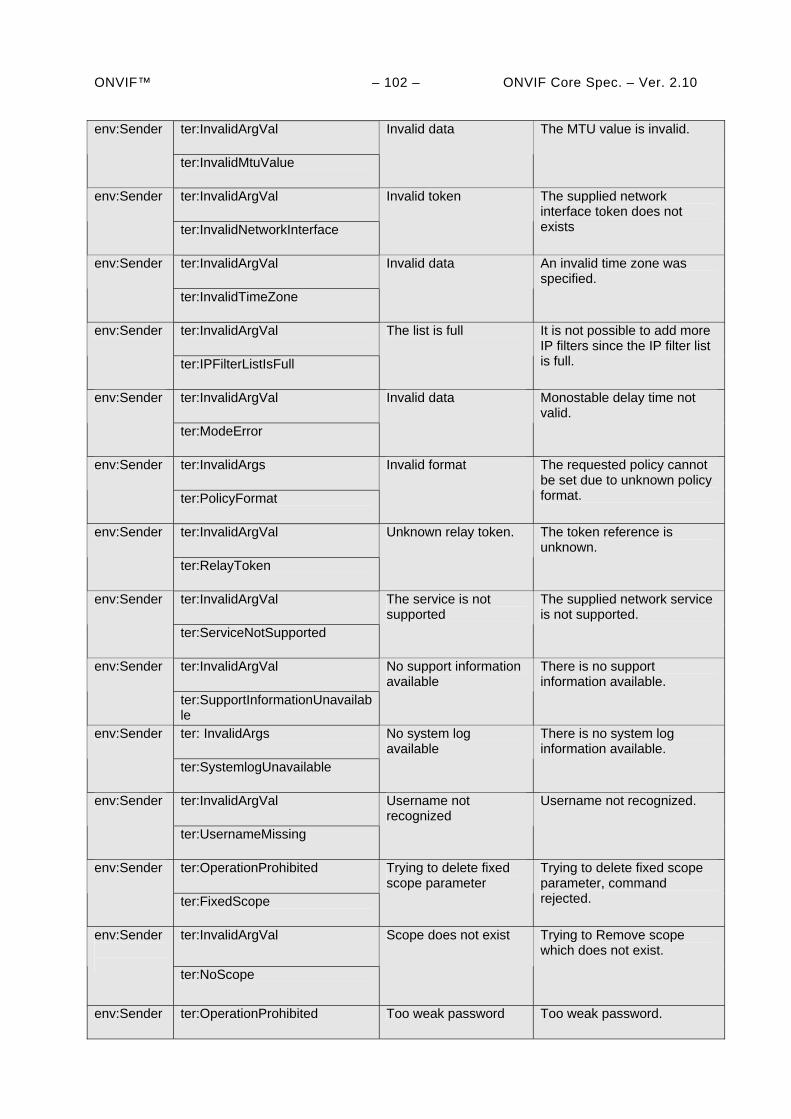
ONVIF™ – 102 – ONVIF Core Spec. – Ver. 2.10
ter:InvalidArgVal env:Sender
ter:InvalidMtuValue
Invalid data The MTU value is invalid.
ter:InvalidArgVal env:Sender
ter:InvalidNetworkInterface
Invalid token The supplied network interface token does not exists
ter:InvalidArgVal env:Sender
ter:InvalidTimeZone
Invalid data An invalid time zone was specified.
ter:InvalidArgVal env:Sender
ter:IPFilterListIsFull
The list is full It is not possible to add more IP filters since the IP filter list is full.
ter:InvalidArgVal env:Sender
ter:ModeError
Invalid data Monostable delay time not valid.
ter:InvalidArgs env:Sender
ter:PolicyFormat
Invalid format The requested policy cannot be set due to unknown policy format.
ter:InvalidArgVal env:Sender
ter:RelayToken
Unknown relay token. The token reference is unknown.
ter:InvalidArgVal env:Sender
ter:ServiceNotSupported
The service is not supported
The supplied network service is not supported.
ter:InvalidArgVal env:Sender
ter:SupportInformationUnavailable
No support information available
There is no support information available.
ter: InvalidArgs env:Sender
ter:SystemlogUnavailable
No system log available
There is no system log information available.
ter:InvalidArgVal env:Sender
ter:UsernameMissing
Username not recognized
Username not recognized.
ter:OperationProhibited env:Sender
ter:FixedScope
Trying to delete fixed scope parameter
Trying to delete fixed scope parameter, command rejected.
ter:InvalidArgVal env:Sender
ter:NoScope
Scope does not exist Trying to Remove scope which does not exist.
env:Sender ter:OperationProhibited Too weak password Too weak password.
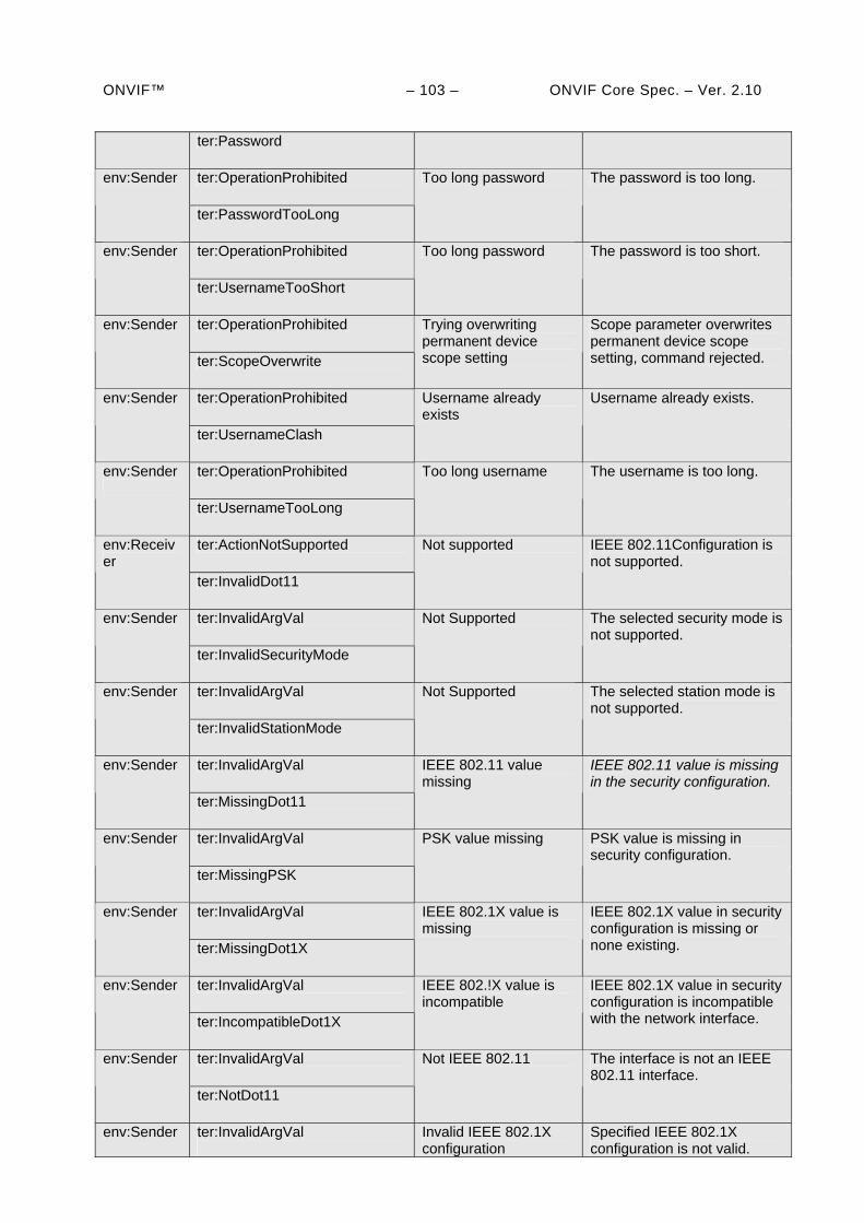
ONVIF™ – 103 – ONVIF Core Spec. – Ver. 2.10
ter:Password
ter:OperationProhibited env:Sender
ter:PasswordTooLong
Too long password The password is too long.
ter:OperationProhibited env:Sender
ter:UsernameTooShort
Too long password The password is too short.
ter:OperationProhibited env:Sender
ter:ScopeOverwrite
Trying overwriting permanent device scope setting
Scope parameter overwrites permanent device scope setting, command rejected.
ter:OperationProhibited env:Sender
ter:UsernameClash
Username already exists
Username already exists.
ter:OperationProhibited env:Sender
ter:UsernameTooLong
Too long username The username is too long.
ter:ActionNotSupported env:Receiver
ter:InvalidDot11
Not supported IEEE 802.11Configuration is not supported.
ter:InvalidArgVal env:Sender
ter:InvalidSecurityMode
Not Supported The selected security mode is not supported.
ter:InvalidArgVal env:Sender
ter:InvalidStationMode
Not Supported The selected station mode is not supported.
ter:InvalidArgVal env:Sender
ter:MissingDot11
IEEE 802.11 value missing
IEEE 802.11 value is missing in the security configuration.
ter:InvalidArgVal env:Sender
ter:MissingPSK
PSK value missing PSK value is missing in security configuration.
ter:InvalidArgVal env:Sender
ter:MissingDot1X
IEEE 802.1X value is missing
IEEE 802.1X value in security configuration is missing or none existing.
ter:InvalidArgVal env:Sender
ter:IncompatibleDot1X
IEEE 802.!X value is incompatible
IEEE 802.1X value in security configuration is incompatible with the network interface.
ter:InvalidArgVal env:Sender
ter:NotDot11
Not IEEE 802.11 The interface is not an IEEE 802.11 interface.
env:Sender ter:InvalidArgVal
Invalid IEEE 802.1X configuration
Specified IEEE 802.1X configuration is not valid.
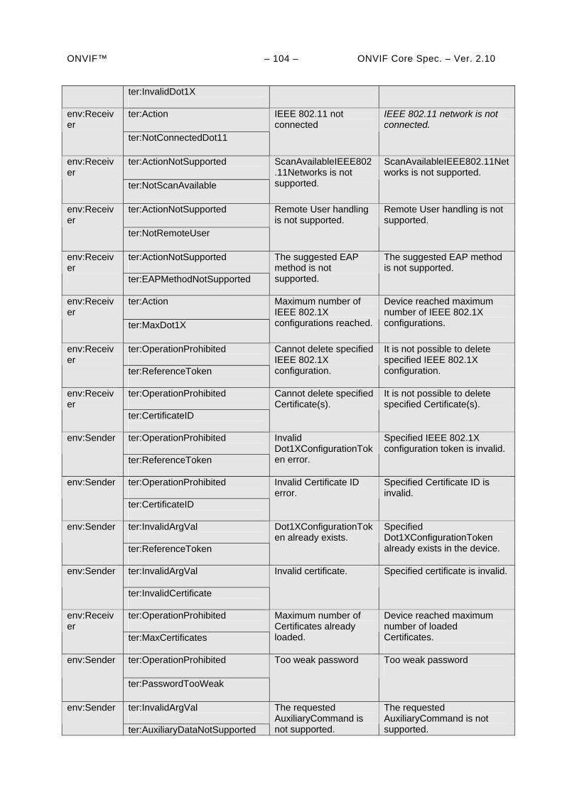
ONVIF™ – 104 – ONVIF Core Spec. – Ver. 2.10
ter:InvalidDot1X ter:Action env:Receiv
er ter:NotConnectedDot11
IEEE 802.11 not connected
IEEE 802.11 network is not connected.
ter:ActionNotSupported env:Receiver
ter:NotScanAvailable
ScanAvailableIEEE802.11Networks is not supported.
ScanAvailableIEEE802.11Networks is not supported.
ter:ActionNotSupported env:Receiver
ter:NotRemoteUser
Remote User handling is not supported.
Remote User handling is not supported.
ter:ActionNotSupported
env:Receiver ter:EAPMethodNotSupported
The suggested EAP method is not supported.
The suggested EAP method is not supported.
ter:Action env:Receiver
ter:MaxDot1X
Maximum number of IEEE 802.1X configurations reached.
Device reached maximum number of IEEE 802.1X configurations.
ter:OperationProhibited
env:Receiver
ter:ReferenceToken
Cannot delete specified IEEE 802.1X configuration.
It is not possible to delete specified IEEE 802.1X configuration.
ter:OperationProhibited
env:Receiver
ter:CertificateID
Cannot delete specified Certificate(s).
It is not possible to delete specified Certificate(s).
ter:OperationProhibited
env:Sender
ter:ReferenceToken
Invalid Dot1XConfigurationToken error.
Specified IEEE 802.1X configuration token is invalid.
ter:OperationProhibited
env:Sender
ter:CertificateID
Invalid Certificate ID error.
Specified Certificate ID is invalid.
ter:InvalidArgVal
env:Sender
ter:ReferenceToken
Dot1XConfigurationToken already exists.
Specified Dot1XConfigurationToken already exists in the device.
ter:InvalidArgVal
env:Sender
ter:InvalidCertificate
Invalid certificate. Specified certificate is invalid.
ter:OperationProhibited
env:Receiver
ter:MaxCertificates
Maximum number of Certificates already loaded.
Device reached maximum number of loaded Certificates.
ter:OperationProhibited env:Sender
ter:PasswordTooWeak
Too weak password Too weak password
ter:InvalidArgVal
env:Sender
ter:AuxiliaryDataNotSupported
The requested AuxiliaryCommand is not supported.
The requested AuxiliaryCommand is not supported.
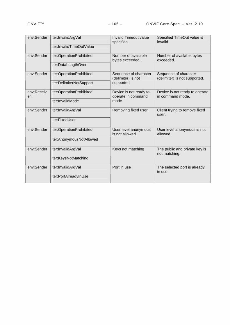
ONVIF™ – 105 – ONVIF Core Spec. – Ver. 2.10
ter:InvalidArgVal
env:Sender
ter:InvalidTimeOutValue
Invalid Timeout value specified.
Specified TimeOut value is invalid.
ter:OperationProhibited
env:Sender
ter:DataLengthOver
Number of available bytes exceeded.
Number of available bytes exceeded.
ter:OperationProhibited
env:Sender
ter:DelimiterNotSupport
Sequence of character (delimiter) is not supported.
Sequence of character (delimiter) is not supported.
ter:OperationProhibited
env:Receiver
ter:InvalidMode
Device is not ready to operate in command mode.
Device is not ready to operate in command mode.
ter:InvalidArgVal env:Sender
ter:FixedUser
Removing fixed user Client trying to remove fixed user.
ter:OperationProhibited env:Sender
ter:AnonymousNotAllowed
User level anonymous is not allowed.
User level anonymous is not allowed.
ter:InvalidArgVal
env:Sender
ter:KeysNotMatching
Keys not matching The public and private key is not matching.
ter:InvalidArgVal
env:Sender
ter:PortAlreadyInUse
Port in use The selected port is already in use.
ONVIF™ – 106 – ONVIF Core Spec. – Ver. 2.10
9 Event handling
An event is an action or occurrence detected by a device that a client can subscribe to. Events are handled through the event service. An ONVIF compliant device shall provide an event services as defined in [ONVIF Event WSDL]. Both device and client shall support [WS-Addressing] for event services.
Event Handling in this standard is based on the [WS-BaseNotification] and [WS-Topics] specifications. This standard requires the implementation of the basic notification interface as described in section 9.1, which conforms completely to the [WS-BaseNotification] specification. In addition, the device shall implement the Real-time Pull-Point Notification Interface and the Notification Streaming Interface as introduced in sections 9.2 and 9.3, respectively.
This standard introduces notification message extensions that allow a client to track object properties (such as video analytics object properties) through events. Properties are defined in Section 9.4.
The description of event payload and their filtering within subscriptions is discussed in Section 9.5. Section 9.6 describes how Synchronization Point can be requested by clients using one of the three Notification Interfaces. Section 9.7 describes the integration of Topics. Section 9.9 discusses the handling of faults.
The last section demonstrates in detail the usage of the Real-Time Pull-Point Notification Interface including Message Filtering and Topic Set. Examples for the basic notification interface can be found in the corresponding [WS-BaseNotification] specification.
9.1 Basic Notification Interface
Section 9.1.1 briefly introduces the Basic Notification Interface of the [WS-BaseNotification] specification. Section 9.1.2 summarizes the mandatory and the optional interfaces of the [WS-BaseNotification] specification.
9.1.1 Introduction
The following logical entities participate in the notification pattern:
Client: implements the NotificationConsumer interface.
Event Service: implements the NotificationProducer interface.
Subscription Manager: implements the BaseSubscriptionManager interface.
The Event Service and the Subscription Manager should be instantiated on a device.
Typical messages exchanged between the entities are shown in the sequence diagram in Figure 9. First, the client establishes a connection to the Event Service. The client can then subscribe for certain notifications by sending a SubscriptionRequest. If the Event Service accepts the Subscription, it dynamically instantiates a SubscriptionManager representing the Subscription. The Event Service shall return the WS-Endpoint-Address of the SubscriptionManager in the SubscriptionResponse.
In order to transmit notifications matching the Subscription, another connection is established from the Event Service to the client. Via this connection, the Event Service sends a one-way Notify message to the NotificationConsumer interface of the client. Corresponding notifications can be sent at any time by the Event Service to the client, while the Subscription is active.
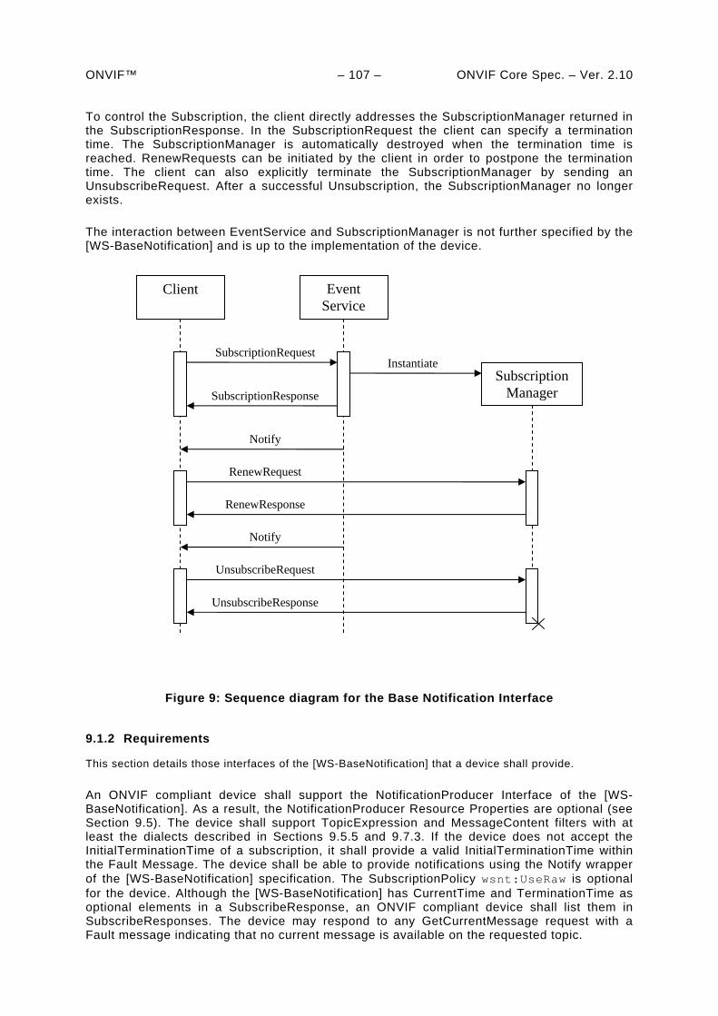
ONVIF™ – 107 – ONVIF Core Spec. – Ver. 2.10 To control the Subscription, the client directly addresses the SubscriptionManager returned in the SubscriptionResponse. In the SubscriptionRequest the client can specify a termination time. The SubscriptionManager is automatically destroyed when the termination time is reached. RenewRequests can be initiated by the client in order to postpone the termination time. The client can also explicitly terminate the SubscriptionManager by sending an UnsubscribeRequest. After a successful Unsubscription, the SubscriptionManager no longer exists.
The interaction between EventService and SubscriptionManager is not further specified by the [WS-BaseNotification] and is up to the implementation of the device.
Client
SubscriptionManager
Notify
UnsubscribeRequest
UnsubscribeResponse
Notify
RenewRequest
RenewResponse
SubscriptionResponse
Instantiate SubscriptionRequest
Event Service
Figure 9: Sequence diagram for the Base Notification Interface
9.1.2 Requirements
This section details those interfaces of the [WS-BaseNotification] that a device shall provide.
An ONVIF compliant device shall support the NotificationProducer Interface of the [WS-BaseNotification]. As a result, the NotificationProducer Resource Properties are optional (see Section 9.5). The device shall support TopicExpression and MessageContent filters with at least the dialects described in Sections 9.5.5 and 9.7.3. If the device does not accept the InitialTerminationTime of a subscription, it shall provide a valid InitialTerminationTime within the Fault Message. The device shall be able to provide notifications using the Notify wrapper of the [WS-BaseNotification] specification. The SubscriptionPolicy wsnt:UseRaw is optional for the device. Although the [WS-BaseNotification] has CurrentTime and TerminationTime as optional elements in a SubscribeResponse, an ONVIF compliant device shall list them in SubscribeResponses. The device may respond to any GetCurrentMessage request with a Fault message indicating that no current message is available on the requested topic.
ONVIF™ – 108 – ONVIF Core Spec. – Ver. 2.10 The implementation of the Pull-Point Interface of the [WS-BaseNotification] on a device is optional.
An ONVIF compliant device shall implement the Base Subscription Manager Interface of the [WS-BaseNotification] specification consisting of the Renew and Unsubscribe operations. The Pausable Subscription Manager Interface is optional. The implementation of Subscriptions as WS-Resources is optional.
9.2 Real-time Pull-Point Notification Interface
This section introduces the Real-time Pull-Point Notification Interface. This interface provides a firewall friendly notification interface that enables real-time polling and initiates all client communications.
This interface is used in the following way:
1) The client asks the device for a PullPointSubscription with the CreatePullPointSubscriptionRequest message. The request contains a detailed description of the Subscription. The ConsumerReference shall be omitted, in contrast to the subscription of the Basic Notification Interface (see Section 9.1).
2) The device evaluates the Subscription and returns either a CreatePullPointSubscriptionResponse when the Subscription is accepted or one of the Fault codes.
3) If the Subscription is accepted, the response contains a WS-EndpointReference to a SubscriptionManager. This WS-Endpoint shall provide a PullMessages operation, which is used by the client to retrieve Notifications and by the Base Subscription Manager Interface described in the [WS-BaseNotification] specification. The Base Subscription Manager Interface consists of PullMessages, Renew and Unsubscribe operations. The sequence diagram of the interaction is shown in Figure 10. The PullMessagesRequest contains Timeout and MessageLimit parameters.
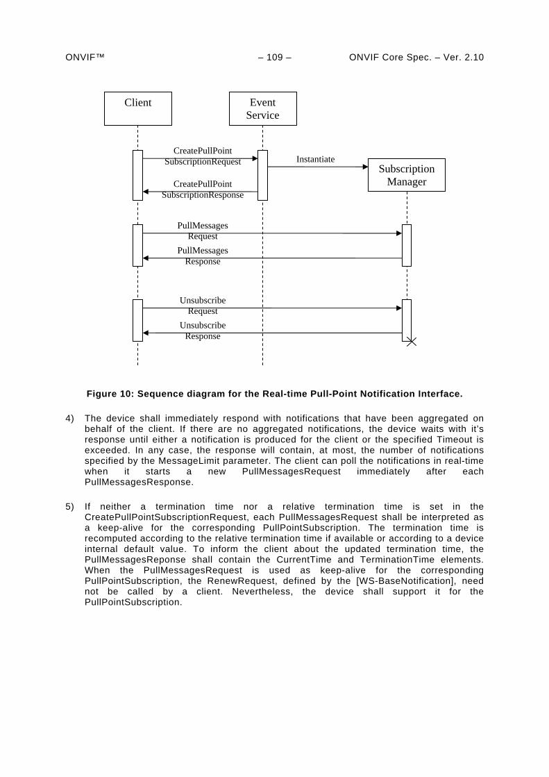
ONVIF™ – 109 – ONVIF Core Spec. – Ver. 2.10
Client
SubscriptionManager
PullMessages Request
PullMessages Response
Unsubscribe Request
Unsubscribe Response
CreatePullPoint SubscriptionResponse
Instantiate CreatePullPoint
SubscriptionRequest
Event Service
Figure 10: Sequence diagram for the Real-time Pull-Point Notification Interface.
4) The device shall immediately respond with notifications that have been aggregated on behalf of the client. If there are no aggregated notifications, the device waits with it’s response until either a notification is produced for the client or the specified Timeout is exceeded. In any case, the response will contain, at most, the number of notifications specified by the MessageLimit parameter. The client can poll the notifications in real-time when it starts a new PullMessagesRequest immediately after each PullMessagesResponse.
5) If neither a termination time nor a relative termination time is set in the CreatePullPointSubscriptionRequest, each PullMessagesRequest shall be interpreted as a keep-alive for the corresponding PullPointSubscription. The termination time is recomputed according to the relative termination time if available or according to a device internal default value. To inform the client about the updated termination time, the PullMessagesReponse shall contain the CurrentTime and TerminationTime elements. When the PullMessagesRequest is used as keep-alive for the corresponding PullPointSubscription, the RenewRequest, defined by the [WS-BaseNotification], need not be called by a client. Nevertheless, the device shall support it for the PullPointSubscription.
ONVIF™ – 110 – ONVIF Core Spec. – Ver. 2.10 9.2.1 Create pull point subscription
The device shall provide the following CreatePullPointSubscription command. If no Filter element is specified the pullpoint shall notify all occurring events to the client.
Table 94: CreatePullPointSubscription command
CreatePullPointSubscription Access Class: READ_MEDIA
Message name Description
CreatePullPointSubscriptionRequest
This message contains the same elements as the SubscriptionRequest of the [WS-BaseNotification] without the ConsumerReference: wsnt:FilterType Filter [0][1] wsnt:AbsoluteOrRelativeTimeType InitialTerminationTime [0][1] xs:any SubscriptionPolicy [0][1]
CreatePullPointSubscriptionResponse
The response contains the same elements as the SubscriptionResponse of the [WS-BaseNotification]: wsa:EndpointReferenceType SubscriptionReference [1][1] xs:dateTime CurrentTime [1][1] xs:dateTime TerminationTime [1][1]
Fault codes Description
The same faults as for Subscription Request of the [WS-BaseNotification] are used.
9.2.2 Pull messages
The device shall provide the following PullMessages command for all SubscriptionManager endpoints returned by the CreatePullPointSubscription command.
The command shall at least support a Timeout of one minute. In case a device supports retrieval of less messages than requested it shall return these without generating a fault.
Table 95: PullMessages command
PullMessages Access Class: READ_MEDIA
Message name Description
PullMessagesRequest This message shall be addressed to a SubscriptionManager in order to pull notifications: xs:duration Timeout [1][1] xs:int MessageLimit [1][1]
PullMessagesResponse The response contains a list of notifications together with an updated TerminationTime for the SubscriptionManager: xs:dateTime CurrentTime [1][1] xs:dateTime TerminationTime [1][1] wsnt:NotificationMessageHolderType NotificationMessage [0][unbounded]
PullMessagesFaultResponse The Timeout exceeds the upper limit supported by the device. The Fault Message shall contain the upper limits for both parameters.
ONVIF™ – 111 – ONVIF Core Spec. – Ver. 2.10
xs:duration MaxTimeout[1][1] xs:int MaxMessageLimit[1][1]
Fault codes Description
No specific fault codes.
9.3 Notification Streaming Interface
Section “Metadata Configuration“ of the ONVIF Media Service Specification describes the creation, deletion and modification of metadata configurations. Certain metadata configurations can contain multiple subscriptions whose structure is the same as that for a notification subscription. When a metadata configuration containing subscriptions has been assigned to a profile, a client uses that profile to get an RTP stream that includes the configured notifications as metadata. The notification streaming via RTP shall be implemented by an ONVIF compliant device.
The [WS-BaseNotification] defines the element wsnt:NotificationMessage to pack the Message Payload, the Topic and the ProducerReference. The structure of this message is the same as that for direct notification requests (the format is described in Section 9.5). Multiple instances of the wsnt:NotificationMessage elements can be placed within a metadata document introduced in the Real-time Viewing section.
There is no explicit SubscriptionReference with streaming notifications. Therefore, the wsnt:NotificationMessage shall not contain the SubscriptionReference element.
9.4 Properties
A Property is a collection of name and value pairs representing a unique and addressable set of data. They are uniquely identified by the combination of their Topic, Source and Key values and are packaged like ordinary events. A Property also contains an additional flag, stating whether it is newly created, has changed or has been deleted.
When a client subscribes to a topic representing a certain property, the device shall provide notifications informing the client of all objects with the requested property, which are alive at the time of the subscription. An client can also request the values of all currently alive properties the client has subscribed to at any time by asking for a synchronization point (see section 9.6).
The property interface is defined in this standard in order to group all property related events together and to present uniformly to clients. It is recommended to use the property interface wherever applicable. Section 9.5 explains the structure of events and properties in detail.
9.4.1 Property Example
The following video analytics example demonstrates the dynamic behaviour of properties: The rule engine interface of the video analytics detector can define fields. Such a detector field is described by a polygon in the image plane. For each object in the scene, the rule engine determines which objects are within the polygon. A client can access this information by subscribing to the corresponding ObjectsInside property of the detector field. Each time an object appears in the scene, a new ObjectsInside property is created. The client is informed by a corresponding “property created” notification indicating if the object appeared inside or outside the polygon. Each time an object enters or leaves the polygon, a “property changed” notification is produced indicating that the ObjectsInside property for this object has changed. When an object leaves the scene, the corresponding ObjectsInside property is deleted and the client is informed via a “property deleted” notification.
ONVIF™ – 112 – ONVIF Core Spec. – Ver. 2.10 9.5 Notification Structure
The following code is the schema for the wsnt:NotificationMessage [WS-BaseNotification]:
<xs:complexType name="NotificationMessageHolderType" > <xs:sequence> <xs:element ref="wsnt:SubscriptionReference" minOccurs="0" /> <xs:element ref="wsnt:Topic" minOccurs="0" /> <xs:element ref="wsnt:ProducerReference" minOccurs="0" /> <xs:element name="Message"> <xs:complexType> <xs:sequence> <xs:any namespace="##any" processContents="lax" /> </xs:sequence> </xs:complexType> </xs:element> </xs:sequence> </xs:complexType> <xs:element name="NotificationMessage" type="wsnt:NotificationMessageHolderType"/>
This corresponds to the following XML structure:
<wsnt:NotificationMessage> <wsnt:SubscriptionReference> wsa:EndpointReferenceType </wsnt:SubscriptionReference> <wsnt:Topic Dialect="xs:anyURI"> … </wsnt:Topic>? <wsnt:ProducerReference> wsa:EndpointReferenceType </wsnt:ProducerReference> <wsnt:Message> … </wsnt:Message> </wsnt:NotificationMessage>
where the wsnt:Message element contains the actual notification payload. The XML type of the Message element can be specified within a TopicTree definition (see Section 9.7).
Section 9.5.1 gives an overview of the information a client retrieves through notifications. Section 9.5.2 gives a detailed formatting of the Message payload, and Section 9.5.4 introduces a description language for the Message payload. Section 9.5.5 defines the grammar used in a subscription to filter notifications by their Message content.
9.5.1 Notification information
A notification answers at least the following questions:
When did it happen?
Who produced the event?
What happened?
The “when” question is answered by adding a time attribute to the Message element of the NotificationMessage. An ONVIF compliant device shall include the time attribute to the Message element.
The “who” question is split into two parts. One part is the WS-Endpoint which identifies the device or a service within the device where the notification has been produced. Therefore, the WS-Endpoint should be specified within the ProducerReference Element of the NotificationMessage. The second part is the identification of the component within the WS-
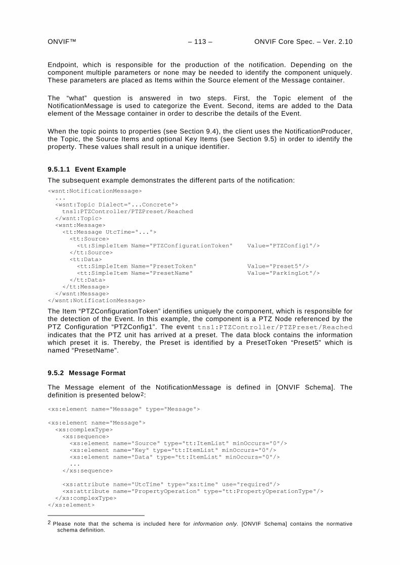
ONVIF™ – 113 – ONVIF Core Spec. – Ver. 2.10
Endpoint, which is responsible for the production of the notification. Depending on the component multiple parameters or none may be needed to identify the component uniquely. These parameters are placed as Items within the Source element of the Message container.
The “what” question is answered in two steps. First, the Topic element of the NotificationMessage is used to categorize the Event. Second, items are added to the Data element of the Message container in order to describe the details of the Event.
When the topic points to properties (see Section 9.4), the client uses the NotificationProducer, the Topic, the Source Items and optional Key Items (see Section 9.5) in order to identify the property. These values shall result in a unique identifier.
9.5.1.1 Event Example
The subsequent example demonstrates the different parts of the notification:
<wsnt:NotificationMessage> ... <wsnt:Topic Dialect="...Concrete"> tns1:PTZController/PTZPreset/Reached </wsnt:Topic> <wsnt:Message> <tt:Message UtcTime="..."> <tt:Source> <tt:SimpleItem Name="PTZConfigurationToken" Value="PTZConfig1"/> </tt:Source> <tt:Data> <tt:SimpleItem Name="PresetToken" Value="Preset5"/> <tt:SimpleItem Name="PresetName" Value="ParkingLot"/> </tt:Data> </tt:Message> </wsnt:Message> </wsnt:NotificationMessage>
The Item “PTZConfigurationToken” identifies uniquely the component, which is responsible for the detection of the Event. In this example, the component is a PTZ Node referenced by the PTZ Configuration “PTZConfig1”. The event tns1:PTZController/PTZPreset/Reached indicates that the PTZ unit has arrived at a preset. The data block contains the information which preset it is. Thereby, the Preset is identified by a PresetToken “Preset5” which is named “PresetName”.
9.5.2 Message Format
The Message element of the NotificationMessage is defined in [ONVIF Schema]. The definition is presented below2:
<xs:element name="Message" type="Message"> <xs:element name="Message"> <xs:complexType> <xs:sequence> <xs:element name="Source" type="tt:ItemList" minOccurs="0"/> <xs:element name="Key" type="tt:ItemList" minOccurs="0"/> <xs:element name="Data" type="tt:ItemList" minOccurs="0"/> ... </xs:sequence> <xs:attribute name="UtcTime" type="xs:time" use="required"/> <xs:attribute name="PropertyOperation" type="tt:PropertyOperationType"/> </xs:complexType> </xs:element>
2 Please note that the schema is included here for information only. [ONVIF Schema] contains the normative
schema definition.
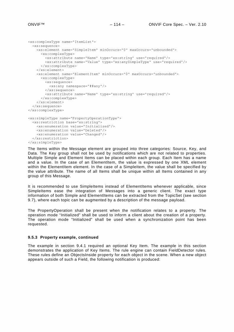
ONVIF™ – 114 – ONVIF Core Spec. – Ver. 2.10 <xs:complexType name="ItemList"> <xs:sequence> <xs:element name="SimpleItem" minOccurs="0" maxOccurs="unbounded"> <xs:complexType> <xs:attribute name="Name" type="xs:string" use="required"/> <xs:attribute name="Value" type="xs:anySimpleType" use="required"/> </xs:complexType> </xs:element> <xs:element name="ElementItem" minOccurs="0" maxOccurs="unbounded"> <xs:complexType> <xs:sequence> <xs:any namespace="##any"/> </xs:sequence> <xs:attribute name="Name" type="xs:string" use="required"/> </xs:complexType> </xs:element> </xs:sequence> </xs:complexType> <xs:simpleType name="PropertyOperationType"> <xs:restriction base="xs:string"> <xs:enumeration value="Initialized"/> <xs:enumeration value="Deleted"/> <xs:enumeration value="Changed"/> </xs:restriction> </xs:simpleType>
The Items within the Message element are grouped into three categories: Source, Key, and Data. The Key group shall not be used by notifications which are not related to properties. Multiple Simple and Element Items can be placed within each group. Each Item has a name and a value. In the case of an ElementItem, the value is expressed by one XML element within the ElementItem element. In the case of a SimpleItem, the value shall be specified by the value attribute. The name of all Items shall be unique within all Items contained in any group of this Message.
It is recommended to use SimpleItems instead of ElementItems whenever applicable, since SimpleItems ease the integration of Messages into a generic client. The exact type information of both Simple and ElementItems can be extracted from the TopicSet (see section 9.7), where each topic can be augmented by a description of the message payload.
The PropertyOperation shall be present when the notification relates to a property. The operation mode “Initialized” shall be used to inform a client about the creation of a property. The operation mode “Initialized” shall be used when a synchronization point has been requested.
9.5.3 Property example, continued
The example in section 9.4.1 required an optional Key Item. The example in this section demonstrates the application of Key Items. The rule engine can contain FieldDetector rules. These rules define an ObjectsInside property for each object in the scene. When a new object appears outside of such a Field, the following notification is produced:
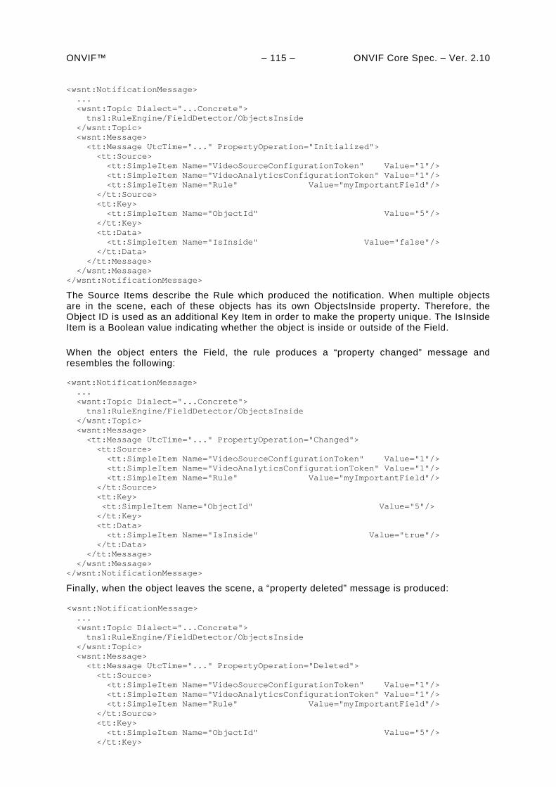
ONVIF™ – 115 – ONVIF Core Spec. – Ver. 2.10 <wsnt:NotificationMessage> ... <wsnt:Topic Dialect="...Concrete"> tns1:RuleEngine/FieldDetector/ObjectsInside </wsnt:Topic> <wsnt:Message> <tt:Message UtcTime="..." PropertyOperation="Initialized"> <tt:Source> <tt:SimpleItem Name="VideoSourceConfigurationToken" Value="1"/> <tt:SimpleItem Name="VideoAnalyticsConfigurationToken" Value="1"/> <tt:SimpleItem Name="Rule" Value="myImportantField"/> </tt:Source> <tt:Key> <tt:SimpleItem Name="ObjectId" Value="5"/> </tt:Key> <tt:Data> <tt:SimpleItem Name="IsInside" Value="false"/> </tt:Data> </tt:Message> </wsnt:Message> </wsnt:NotificationMessage>
The Source Items describe the Rule which produced the notification. When multiple objects are in the scene, each of these objects has its own ObjectsInside property. Therefore, the Object ID is used as an additional Key Item in order to make the property unique. The IsInside Item is a Boolean value indicating whether the object is inside or outside of the Field.
When the object enters the Field, the rule produces a “property changed” message and resembles the following:
<wsnt:NotificationMessage> ... <wsnt:Topic Dialect="...Concrete"> tns1:RuleEngine/FieldDetector/ObjectsInside </wsnt:Topic> <wsnt:Message> <tt:Message UtcTime="..." PropertyOperation="Changed"> <tt:Source> <tt:SimpleItem Name="VideoSourceConfigurationToken" Value="1"/> <tt:SimpleItem Name="VideoAnalyticsConfigurationToken" Value="1"/> <tt:SimpleItem Name="Rule" Value="myImportantField"/> </tt:Source> <tt:Key> <tt:SimpleItem Name="ObjectId" Value="5"/> </tt:Key> <tt:Data> <tt:SimpleItem Name="IsInside" Value="true"/> </tt:Data> </tt:Message> </wsnt:Message> </wsnt:NotificationMessage>
Finally, when the object leaves the scene, a “property deleted” message is produced:
<wsnt:NotificationMessage> ... <wsnt:Topic Dialect="...Concrete"> tns1:RuleEngine/FieldDetector/ObjectsInside </wsnt:Topic> <wsnt:Message> <tt:Message UtcTime="..." PropertyOperation="Deleted"> <tt:Source> <tt:SimpleItem Name="VideoSourceConfigurationToken" Value="1"/> <tt:SimpleItem Name="VideoAnalyticsConfigurationToken" Value="1"/> <tt:SimpleItem Name="Rule" Value="myImportantField"/> </tt:Source> <tt:Key> <tt:SimpleItem Name="ObjectId" Value="5"/> </tt:Key>
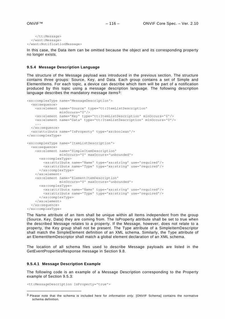
ONVIF™ – 116 – ONVIF Core Spec. – Ver. 2.10
</tt:Message> </wsnt:Message> </wsnt:NotificationMessage>
In this case, the Data item can be omitted because the object and its corresponding property no longer exists.
9.5.4 Message Description Language
The structure of the Message payload was introduced in the previous section. The structure contains three groups: Source, Key, and Data. Each group contains a set of Simple and ElementItems. For each topic, a device can describe which Item will be part of a notification produced by this topic using a message description language. The following description language describes the mandatory message items3:
<xs:complexType name="MessageDescription"> <xs:sequence> <xs:element name="Source" type="tt:ItemListDescription" minOccurs="0"/> <xs:element name="Key" type="tt:ItemListDescription" minOccurs="0"/> <xs:element name="Data" type="tt:ItemListDescription" minOccurs="0"/> ... </xs:sequence> <xs:attribute name="IsProperty" type="xs:boolean"/> </xs:complexType> <xs:complexType name="ItemListDescription"> <xs:sequence> <xs:element name="SimpleItemDescription" minOccurs="0" maxOccurs="unbounded"> <xs:complexType> <xs:attribute name="Name" type="xs:string" use="required"/> <xs:attribute name="Type" type="xs:string" use="required"/> </xs:complexType> </xs:element> <xs:element name="ElementItemDescription" minOccurs="0" maxOccurs="unbounded"> <xs:complexType> <xs:attribute name="Name" type="xs:string" use="required"/> <xs:attribute name="Type" type="xs:string" use="required"/> </xs:complexType> </xs:element> </xs:sequence> </xs:complexType>
The Name attribute of an Item shall be unique within all Items independent from the group (Source, Key, Data) they are coming from. The IsProperty attribute shall be set to true when the described Message relates to a property. If the Message, however, does not relate to a property, the Key group shall not be present. The Type attribute of a SimpleItemDescriptor shall match the SimpleElement definition of an XML schema. Similarly, the Type attribute of an ElementItemDescriptor shall match a global element declaration of an XML schema.
The location of all schema files used to describe Message payloads are listed in the GetEventPropertiesResponse message in Section 9.8.
9.5.4.1 Message Description Example
The following code is an example of a Message Description corresponding to the Property example of Section 9.5.3:
<tt:MessageDescription IsProperty="true">
3 Please note that the schema is included here for information only. [ONVIF Schema] contains the normative
schema definition.
ONVIF™ – 117 – ONVIF Core Spec. – Ver. 2.10 <tt:Source> <tt:SimpleItemDescription Name="VideoSourceConfigurationToken" Type="tt:ReferenceToken"/> <tt:SimpleItemDescriptionD Name="VideoAnalyticsConfigurationToken" Type="tt:ReferenceToken"/> <tt:SimpleItemDescription Name="Rule" Type="xs:string"/> </tt:Source> <tt:Key> <tt:SimpleItemDescription Name="ObjectId" Type="xs:integer"/> </tt:Key> <tt:Data> <tt:SimpleItemDescription Name="IsInside" Type="xs:boolean"/> </tt:Data> </tt:MessageDescription>
9.5.5 Message Content Filter
In the Subscription request, a client can filter notifications by TopicExpression (see Section 9.7.3) and by MessageContent. For the latter, the [WS-BaseNotification] proposes the XPath 1.0 dialect. Due to the specific Message structure required by this specification, the specification requires a subset of the XPath 1.0 syntax. An ONVIF compliant device shall implement the subset of XPath 1.0. The corresponding dialect can be referenced with the following URI:
Dialect=http://www.onvif.org/ver10/tev/messageContentFilter/ItemFilter
Precedence and associativity: The 'and' operation has higher precedence than the 'or' operation. Both 'and' and 'or' operations are left associative.
The precedence and associativity of 'and' and 'or' operations in the following grammar definition are identical to XPath 1.0 specifications.
The structure of the Expressions is as follows:
[1] Expression ::= BoolExpr | Expression ‘and’ Expression | Expression ‘or’ Expression | ‘(‘ Expression ‘)’ | ‘not’ ‘(‘ Expression ‘)’
[2] BoolExpr ::= ‘boolean’ ‘(‘ PathExpr ‘)’
[3] PathExpr ::= [‘//’Prefix?’SimpleItem‘ | ’//’Prefix?’ElementItem‘ ] NodeTest
[4] Prefix::= NamespacePrefix’:’ | ‘’
[5] NodeTest ::= ‘[‘ AttrExpr ‘]’
[6] AttrExpr ::= AttrComp | AttrExpr ‘and’ AttrExpr | AttrExpr ‘or‘ AttrExpr | ‘(‘ AttrExpr ‘)‘ | ‘not’ ‘(‘ AttrExpr ‘)‘
[7] AttrComp ::= Attribute ‘=’ ‘”’ String ‘”’
[8] Attribute ::= ‘@Name’ | ‘@Value’
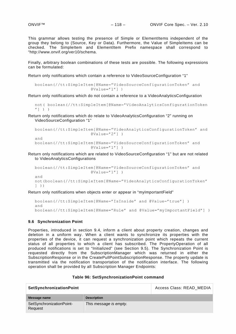
ONVIF™ – 118 – ONVIF Core Spec. – Ver. 2.10 This grammar allows testing the presence of Simple or ElementItems independent of the group they belong to (Source, Key or Data). Furthermore, the Value of SimpleItems can be checked. The SimpleItem and ElementItem Prefix namespace shall correspond to “http://www.onvif.org/ver10/schema.
Finally, arbitrary boolean combinations of these tests are possible. The following expressions can be formulated:
Return only notifications which contain a reference to VideoSourceConfiguration “1” boolean(//tt:SimpleItem[@Name=”VideoSourceConfigurationToken” and @Value=”1”] )
Return only notifications which do not contain a reference to a VideoAnalyticsConfiguration not( boolean(//tt:SimpleItem[@Name=”VideoAnalyticsConfigurationToken”] ) )
Return only notifications which do relate to VideoAnalyticsConfiguration “2” running on VideoSourceConfiguration “1” boolean(//tt:SimpleItem[@Name=”VideoAnalyticsConfigurationToken” and @Value=”2”] ) and boolean(//tt:SimpleItem[@Name=”VideoSourceConfigurationToken” and @Value=”1”] )
Return only notifications which are related to VideoSourceConfiguration “1” but are not related to VideoAnalyticsConfigurations boolean(//tt:SimpleItem[@Name=”VideoSourceConfigurationToken” and @Value=”1”] ) and not(boolean(//tt:SimpleItem[@Name=”VideoAnalyticsConfigurationToken”] ))
Return only notifications when objects enter or appear in “myImportantField” boolean(//tt:SimpleItem[@Name=”IsInside” and @Value=”true”] ) and boolean(//tt:SimpleItem[@Name=”Rule” and @Value=”myImportantField”] )
9.6 Synchronization Point
Properties, introduced in section 9.4, inform a client about property creation, changes and deletion in a uniform way. When a client wants to synchronize its properties with the properties of the device, it can request a synchronization point which repeats the current status of all properties to which a client has subscribed. The PropertyOperation of all produced notifications is set to “Initialized” (see Section 9.5). The Synchronization Point is requested directly from the SubscriptionManager which was returned in either the SubscriptionResponse or in the CreatePullPointSubscriptionResponse. The property update is transmitted via the notification transportation of the notification interface. The following operation shall be provided by all Subscription Manager Endpoints:
Table 96: SetSynchronizationPoint command
SetSynchronizationPoint Access Class: READ_MEDIA
Message name Description
SetSynchronizationPoint-Request
This message is empty.
ONVIF™ – 119 – ONVIF Core Spec. – Ver. 2.10 SetSynchronizationPoint-Response
This message is empty.
Fault codes Description
No command specific faults!
When a client uses the notification streaming interface, the client should use the SetSynchronizationPoint operation defined in the ONVIF Media Service Specification.
9.7 Topic Structure
This standard extends the Topic framework defined in the [WS-Topics] specification. Section 9.7.1 describes an ONVIF Topic Namespace, which should be taken as a basis for vendor specific topics. The Appendix 0 shows typical examples for such extensions. Section 9.7.2 defines an interface to topic properties. This interface shall be implemented by an ONVIF compliant device. Section 9.7.3 incorporates the Message Description Language defined in section 9.5.4 into the TopicSet structure. All topics grown from the ONVIF Topic Namespace describes the type of a topic according to section 9.7.3. Section 9.7.3 defines the Topic Expression Dialects which are supported by a device.
9.7.1 ONVIF Topic Namespace
The [WS-Topics] specification distinguishes between the definition of a Topic Tree belonging to a certain Topic Namespace and the Topic Set supported by a certain Web Service. This distinction allows vendors to refer to a common Topic Namespace while only using a portion of the defined Topics.
If the Topic Tree of an existing Topic Namespace covers only a subset of the topics available by a device, the Topic Tree can be grown by defining a new Topic Namespace. A new Topic Namespace is defined by appending a new topic to an existing Topic Namespace as described in the [WS-Topics] specification.
The following root topics are defined in the ONVIF Namespace. All notifications referring to these topics shall use the Message Format as described in Section 9.5.2.
<wstop:TopicNamespace name="ONVIF" targetNamespace="http://www.onvif.org/ver10/topics" > <wstop:Topic name="Device"/> <wstop:Topic name="VideoSource"/> <wstop:Topic name="VideoEncoder"/> <wstop:Topic name="VideoAnalytics"/> <wstop:Topic name="RuleEngine"/> <wstop:Topic name="PTZController"/> <wstop:Topic name="AudioSource"/> <wstop:Topic name="AudioEncoder"/> <wstop:Topic name="UserAlarm"/> <wstop:Topic name="MediaControl"/> <wstop:Topic name="RecordingConfig"/> <wstop:Topic name="RecordingHistory"/> <wstop:Topic name="VideoOutput"/> <wstop:Topic name="AudioOutput"/> <wstop:Topic name="VideoDecoder"/> <wstop:Topic name="AudioDecoder"/> <wstop:Topic name=”Receiver”/>
</wstop:TopicNamespace>
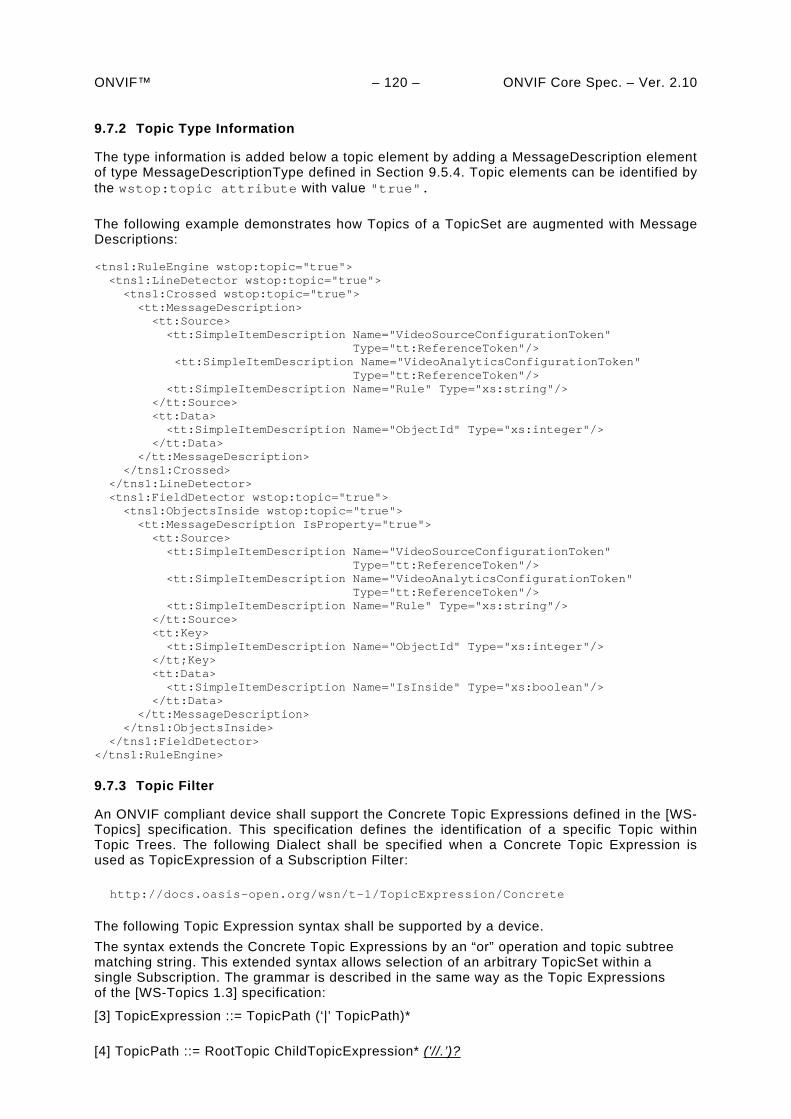
ONVIF™ – 120 – ONVIF Core Spec. – Ver. 2.10 9.7.2 Topic Type Information
The type information is added below a topic element by adding a MessageDescription element of type MessageDescriptionType defined in Section 9.5.4. Topic elements can be identified by the wstop:topic attribute with value "true".
The following example demonstrates how Topics of a TopicSet are augmented with Message Descriptions:
<tns1:RuleEngine wstop:topic="true"> <tns1:LineDetector wstop:topic="true"> <tns1:Crossed wstop:topic="true"> <tt:MessageDescription> <tt:Source> <tt:SimpleItemDescription Name="VideoSourceConfigurationToken" Type="tt:ReferenceToken"/> <tt:SimpleItemDescription Name="VideoAnalyticsConfigurationToken" Type="tt:ReferenceToken"/> <tt:SimpleItemDescription Name="Rule" Type="xs:string"/> </tt:Source> <tt:Data> <tt:SimpleItemDescription Name="ObjectId" Type="xs:integer"/> </tt:Data> </tt:MessageDescription> </tns1:Crossed> </tns1:LineDetector> <tns1:FieldDetector wstop:topic="true"> <tns1:ObjectsInside wstop:topic="true"> <tt:MessageDescription IsProperty="true"> <tt:Source> <tt:SimpleItemDescription Name="VideoSourceConfigurationToken" Type="tt:ReferenceToken"/> <tt:SimpleItemDescription Name="VideoAnalyticsConfigurationToken" Type="tt:ReferenceToken"/> <tt:SimpleItemDescription Name="Rule" Type="xs:string"/> </tt:Source> <tt:Key> <tt:SimpleItemDescription Name="ObjectId" Type="xs:integer"/> </tt;Key> <tt:Data> <tt:SimpleItemDescription Name="IsInside" Type="xs:boolean"/> </tt:Data> </tt:MessageDescription> </tns1:ObjectsInside> </tns1:FieldDetector> </tns1:RuleEngine>
9.7.3 Topic Filter
An ONVIF compliant device shall support the Concrete Topic Expressions defined in the [WS-Topics] specification. This specification defines the identification of a specific Topic within Topic Trees. The following Dialect shall be specified when a Concrete Topic Expression is used as TopicExpression of a Subscription Filter:
http://docs.oasis-open.org/wsn/t-1/TopicExpression/Concrete
The following Topic Expression syntax shall be supported by a device.
The syntax extends the Concrete Topic Expressions by an “or” operation and topic subtree matching string. This extended syntax allows selection of an arbitrary TopicSet within a single Subscription. The grammar is described in the same way as the Topic Expressions of the [WS-Topics 1.3] specification:
[3] TopicExpression ::= TopicPath (‘|’ TopicPath)*
[4] TopicPath ::= RootTopic ChildTopicExpression* ('//.’)?
ONVIF™ – 121 – ONVIF Core Spec. – Ver. 2.10 [5] RootTopic ::= QName
If a namespace prefix is included in the RootTopic, it shall correspond to a valid Topic Namespace definition and the local name shall correspond to the name of a root Topic defined in that namespace.
[6] ChildTopicExpression ::= ‘/’ ChildTopicName
[7] ChildTopicName ::= QName | NCName
The NCName or local part of the QName shall correspond to the name of a Topic within the descendant path from the RootTopic, where each forward slash denotes another level of child Topic elements in the path.
In order to reference this TopicExpression Dialect, the following URI shall be used:
Dialect=http://www.onvif.org/ver10/tev/topicExpression/ConcreteSet
If the TopicExpression ends with the characters “//.” this indicates that the TopicExpression
matches a Topic sub-tree. For example:
“tns1:RuleEngine/FieldDetector//.”
This identifies the sub-tree consisting of tns1:RuleEngine/FieldDetector and all its descendents.
The following examples demonstrate the usage of the ConcreteSet topicExpression:
Look for notifications which have the VideoAnalytics topic as parent topic: <wsnt:TopicExpression Dialect =
"http://www.onvif.org/ver10/tev/topicExpression/ConcreteSet" >
tns1:VideoAnalytics//.
</wsnt:TopicExpression>
Look for notifications which have the VideoAnalytics topic or the RuleEngine as parent topic: <wsnt:TopicExpression Dialect =
"http://www.onvif.org/ver10/tev/topicExpression/ConcreteSet" >
tns1:VideoAnalytics//.|tns1:RuleEngine//.
</wsnt:TopicExpression>
Look for notifications produced by either a LineDetector or a FieldDetector: <wsnt:TopicExpression Dialect =
"http://www.onvif.org/ver10/tev/topicExpression/ConcreteSet">
tns1:RuleEngine/FieldDetector//.|tns1:RuleEngine/LineDetector//.
</wsnt:TopicExpression>
9.8 Get event properties
The [WS-BaseNotification] specification defines a set of optional WS-ResouceProperties. This specification does not require the implementation of the WS-ResourceProperty interface. Instead, the subsequent direct interface shall be implemented by an ONVIF compliant device in order to provide information about the FilterDialects, Schema files and topics supported by the device.
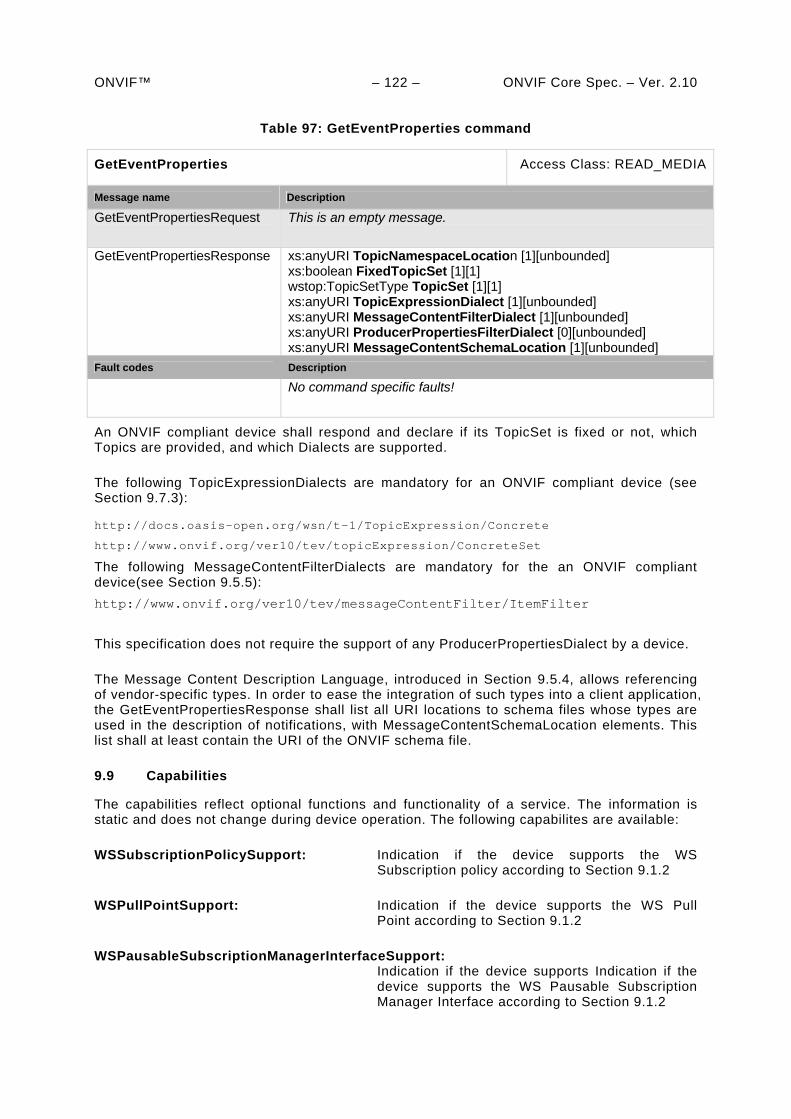
ONVIF™ – 122 – ONVIF Core Spec. – Ver. 2.10
Table 97: GetEventProperties command
GetEventProperties Access Class: READ_MEDIA
Message name Description
GetEventPropertiesRequest This is an empty message.
GetEventPropertiesResponse xs:anyURI TopicNamespaceLocation [1][unbounded] xs:boolean FixedTopicSet [1][1] wstop:TopicSetType TopicSet [1][1] xs:anyURI TopicExpressionDialect [1][unbounded] xs:anyURI MessageContentFilterDialect [1][unbounded] xs:anyURI ProducerPropertiesFilterDialect [0][unbounded] xs:anyURI MessageContentSchemaLocation [1][unbounded]
Fault codes Description
No command specific faults!
An ONVIF compliant device shall respond and declare if its TopicSet is fixed or not, which Topics are provided, and which Dialects are supported.
The following TopicExpressionDialects are mandatory for an ONVIF compliant device (see Section 9.7.3):
http://docs.oasis-open.org/wsn/t-1/TopicExpression/Concrete
http://www.onvif.org/ver10/tev/topicExpression/ConcreteSet
The following MessageContentFilterDialects are mandatory for the an ONVIF compliant device(see Section 9.5.5):
http://www.onvif.org/ver10/tev/messageContentFilter/ItemFilter
This specification does not require the support of any ProducerPropertiesDialect by a device.
The Message Content Description Language, introduced in Section 9.5.4, allows referencing of vendor-specific types. In order to ease the integration of such types into a client application, the GetEventPropertiesResponse shall list all URI locations to schema files whose types are used in the description of notifications, with MessageContentSchemaLocation elements. This list shall at least contain the URI of the ONVIF schema file.
9.9 Capabilities
The capabilities reflect optional functions and functionality of a service. The information is static and does not change during device operation. The following capabilites are available:
WSSubscriptionPolicySupport: Indication if the device supports the WS Subscription policy according to Section 9.1.2
WSPullPointSupport: Indication if the device supports the WS Pull Point according to Section 9.1.2
WSPausableSubscriptionManagerInterfaceSupport: Indication if the device supports Indication if the device supports the WS Pausable Subscription Manager Interface according to Section 9.1.2
ONVIF™ – 123 – ONVIF Core Spec. – Ver. 2.10
Table 98: GetServiceCapabilities command
GetServiceCapabilities Access Class: PRE_AUTH
Message name Description
GetServiceCapabilitiesRequest
This message contains a request for device capabilities.
GetServiceCapabilitiesResponse
The capability response message contains the requested service capabilities using a hierarchical XML capability structure. tev:Capabilities Capabilities [1][1]
Fault codes Description
No command specific faults!
9.10 SOAP Fault Messages
If a device encounters a failure while processing [WS-BaseNotification] messages from either a client or Subscription Manager, then the device shall generate a SOAP 1.2 fault message.
All SOAP 1.2 fault messages shall be generated according to [WS-BaseNotification] and [WS-Topics] specifications.
9.11 Notification example
The following example is a complete communication pattern for notifications. It uses the Real-time Pull-Point Notification Interface to receive notifications.
9.11.1 GetEventPropertiesRequest
<?xml version="1.0" encoding="UTF-8"?> <SOAP-ENV:Envelope xmlns:SOAP-ENV="http://www.w3.org/2003/05/soap-envelope" xmlns:wsa="http://www.w3.org/2005/08/addressing" xmlns:tet="http://www.onvif.org/ver10/events/wsdl"> <SOAP-ENV:Header> <wsa:Action> http://www.onvif.org/ver10/events/wsdl/EventPortType/GetEventPropertiesRequest </wsa:Action> </SOAP-ENV:Header> <SOAP-ENV:Body> <tet:GetEventProperties> </tet:GetEventProperties> </SOAP-ENV:Body> </SOAP-ENV:Envelope>
9.11.2 GetEventPropertiesResponse
In this example, the device response uses the ONVIF topic namespace (the description can be downloaded from http://www.onvif.org/onvif/ver10/topics/topicns.xml). The topic set does not change over time and consists of the single topic tns1:RuleEngine/LineDetector/Crossed. The Message associated with this topic contains information about the VideoSourceConfigurationToken, the
ONVIF™ – 124 – ONVIF Core Spec. – Ver. 2.10 VideoAnalyticsConfigurationToken and the object which has crossed the line. The device supports two TopicExpressionDialects.
<?xml version="1.0" encoding="UTF-8"?> <SOAP-ENV:Envelope xmlns:SOAP-ENV="http://www.w3.org/2003/05/soap-envelope" xmlns:wsa="http://www.w3.org/2005/08/addressing" xmlns:wstop="http://docs.oasis-open.org/wsn/t-1" xmlns:wsnt="http://docs.oasis-open.org/wsn/b-2" xmlns:tet="http://www.onvif.org/ver10/events/wsdl" xmlns:tns1="http://www.onvif.org/ver10/topics" xmlns:tt="http://www.onvif.org/ver10/schema"> <SOAP-ENV:Header> <wsa:Action> http://www.onvif.org/ver10/events/wsdl/EventPortType/GetEventPropertiesResponse </wsa:Action> </SOAP-ENV:Header> <SOAP-ENV:Body> <tet:GetEventPropertiesResponse> <tet:TopicNamespaceLocation> http://www.onvif.org/onvif/ver10/topics/topicns.xml </tet:TopicNamespaceLocation> <wsnt:FixedTopicSet> true </wsnt:FixedTopicSet> <wstop:TopicSet> <tns1:RuleEngine> <tns1:LineDetector> <tns1:Crossed wstop:topic="true"> <tt:MessageDescription> <tt:Source> <tt:SimpleItemDescription Name="VideoSourceConfigurationToken" Type="tt:ReferenceToken"/> <tt:SimpleItemDescription Name="VideoAnalyticsConfigurationToken" Type="tt:ReferenceToken"/> </tt:Source> <tt:Data> <tt:SimpleItemDescription Name="ObjectId" Type="xs:integer"/> </tt:Data> </tt:MessageDescription> </tns1:Crossed> </tns1:LineDetector> </tns1:RuleEngine> </wstop:TopicSet> <wsnt:TopicExpressionDialect> http://www.onvif.org/ver10/tev/topicExpression/ConcreteSet </wsnt:TopicExpressionDialect> <wsnt:TopicExpressionDialect> http://docs.oasis-open.org/wsnt/t-1/TopicExpression/ConcreteSet </wsnt:TopicExpressionDialect> <wsnt:MessageContentFilterDialect> http://www.onvif.org/ver10/tev/messageContentFilter/ItemFilter </wsnt:MessageContentFilterDialect> <tt:MessageContentSchemaLocation> http://www.onvif.org/onvif/ver10/schema/onvif.xsd </tt:MessageContentSchemaLocation> </tet:GetEventPropertiesResponse> </SOAP-ENV:Body> </SOAP-ENV:Envelope>
9.11.3 CreatePullPointSubscription
A client can subscribe to specific notifications with the information from the TopicProperties. The following XML example shows the subscription for notifications produced by the Rule Engine of the device. The client reacts only to notifications that reference VideoAnalyticsConfiguration “2” and VideoSourceConfiguration “1”. The Subscription has a
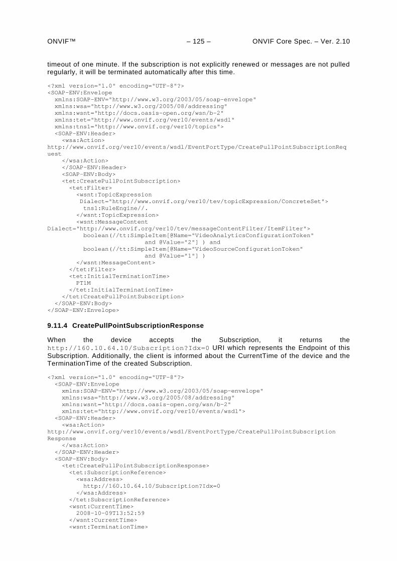
ONVIF™ – 125 – ONVIF Core Spec. – Ver. 2.10 timeout of one minute. If the subscription is not explicitly renewed or messages are not pulled regularly, it will be terminated automatically after this time.
<?xml version="1.0" encoding="UTF-8"?> <SOAP-ENV:Envelope xmlns:SOAP-ENV="http://www.w3.org/2003/05/soap-envelope" xmlns:wsa="http://www.w3.org/2005/08/addressing" xmlns:wsnt="http://docs.oasis-open.org/wsn/b-2" xmlns:tet="http://www.onvif.org/ver10/events/wsdl" xmlns:tns1="http://www.onvif.org/ver10/topics"> <SOAP-ENV:Header> <wsa:Action> http://www.onvif.org/ver10/events/wsdl/EventPortType/CreatePullPointSubscriptionRequest </wsa:Action> </SOAP-ENV:Header> <SOAP-ENV:Body> <tet:CreatePullPointSubscription> <tet:Filter> <wsnt:TopicExpression Dialect="http://www.onvif.org/ver10/tev/topicExpression/ConcreteSet"> tns1:RuleEngine//. </wsnt:TopicExpression> <wsnt:MessageContent Dialect="http://www.onvif.org/ver10/tev/messageContentFilter/ItemFilter"> boolean(//tt:SimpleItem[@Name="VideoAnalyticsConfigurationToken" and @Value="2"] ) and boolean(//tt:SimpleItem[@Name="VideoSourceConfigurationToken" and @Value="1"] ) </wsnt:MessageContent> </tet:Filter> <tet:InitialTerminationTime> PT1M </tet:InitialTerminationTime> </tet:CreatePullPointSubscription> </SOAP-ENV:Body> </SOAP-ENV:Envelope>
9.11.4 CreatePullPointSubscriptionResponse
When the device accepts the Subscription, it returns the http://160.10.64.10/Subscription?Idx=0 URI which represents the Endpoint of this Subscription. Additionally, the client is informed about the CurrentTime of the device and the TerminationTime of the created Subscription.
<?xml version="1.0" encoding="UTF-8"?> <SOAP-ENV:Envelope xmlns:SOAP-ENV="http://www.w3.org/2003/05/soap-envelope" xmlns:wsa="http://www.w3.org/2005/08/addressing" xmlns:wsnt="http://docs.oasis-open.org/wsn/b-2" xmlns:tet="http://www.onvif.org/ver10/events/wsdl"> <SOAP-ENV:Header> <wsa:Action> http://www.onvif.org/ver10/events/wsdl/EventPortType/CreatePullPointSubscriptionResponse </wsa:Action> </SOAP-ENV:Header> <SOAP-ENV:Body> <tet:CreatePullPointSubscriptionResponse> <tet:SubscriptionReference> <wsa:Address> http://160.10.64.10/Subscription?Idx=0 </wsa:Address> </tet:SubscriptionReference> <wsnt:CurrentTime> 2008-10-09T13:52:59 </wsnt:CurrentTime> <wsnt:TerminationTime>
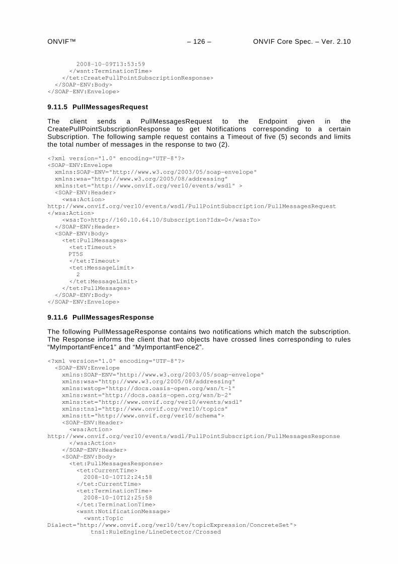
ONVIF™ – 126 – ONVIF Core Spec. – Ver. 2.10 2008-10-09T13:53:59 </wsnt:TerminationTime> </tet:CreatePullPointSubscriptionResponse> </SOAP-ENV:Body> </SOAP-ENV:Envelope>
9.11.5 PullMessagesRequest
The client sends a PullMessagesRequest to the Endpoint given in the CreatePullPointSubscriptionResponse to get Notifications corresponding to a certain Subscription. The following sample request contains a Timeout of five (5) seconds and limits the total number of messages in the response to two (2).
<?xml version="1.0" encoding="UTF-8"?> <SOAP-ENV:Envelope xmlns:SOAP-ENV="http://www.w3.org/2003/05/soap-envelope" xmlns:wsa="http://www.w3.org/2005/08/addressing" xmlns:tet="http://www.onvif.org/ver10/events/wsdl" > <SOAP-ENV:Header> <wsa:Action> http://www.onvif.org/ver10/events/wsdl/PullPointSubscription/PullMessagesRequest </wsa:Action> <wsa:To>http://160.10.64.10/Subscription?Idx=0</wsa:To> </SOAP-ENV:Header> <SOAP-ENV:Body> <tet:PullMessages> <tet:Timeout> PT5S </tet:Timeout> <tet:MessageLimit> 2 </tet:MessageLimit> </tet:PullMessages> </SOAP-ENV:Body> </SOAP-ENV:Envelope>
9.11.6 PullMessagesResponse
The following PullMessageResponse contains two notifications which match the subscription. The Response informs the client that two objects have crossed lines corresponding to rules “MyImportantFence1” and “MyImportantFence2”.
<?xml version="1.0" encoding="UTF-8"?> <SOAP-ENV:Envelope xmlns:SOAP-ENV="http://www.w3.org/2003/05/soap-envelope" xmlns:wsa="http://www.w3.org/2005/08/addressing" xmlns:wstop="http://docs.oasis-open.org/wsn/t-1" xmlns:wsnt="http://docs.oasis-open.org/wsn/b-2" xmlns:tet="http://www.onvif.org/ver10/events/wsdl" xmlns:tns1="http://www.onvif.org/ver10/topics" xmlns:tt="http://www.onvif.org/ver10/schema"> <SOAP-ENV:Header> <wsa:Action> http://www.onvif.org/ver10/events/wsdl/PullPointSubscription/PullMessagesResponse </wsa:Action> </SOAP-ENV:Header> <SOAP-ENV:Body> <tet:PullMessagesResponse> <tet:CurrentTime> 2008-10-10T12:24:58 </tet:CurrentTime> <tet:TerminationTime> 2008-10-10T12:25:58 </tet:TerminationTime> <wsnt:NotificationMessage> <wsnt:Topic Dialect="http://www.onvif.org/ver10/tev/topicExpression/ConcreteSet"> tns1:RuleEngine/LineDetector/Crossed
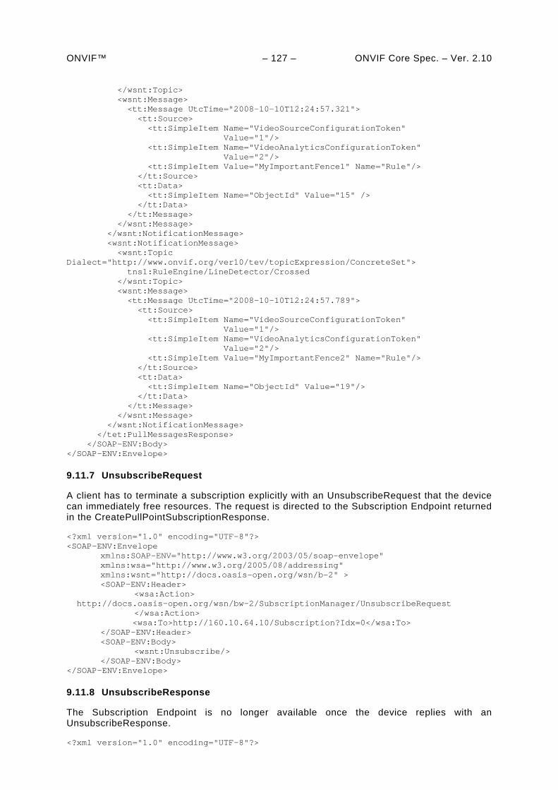
ONVIF™ – 127 – ONVIF Core Spec. – Ver. 2.10 </wsnt:Topic> <wsnt:Message> <tt:Message UtcTime="2008-10-10T12:24:57.321"> <tt:Source> <tt:SimpleItem Name="VideoSourceConfigurationToken" Value="1"/> <tt:SimpleItem Name="VideoAnalyticsConfigurationToken" Value="2"/> <tt:SimpleItem Value="MyImportantFence1" Name="Rule"/> </tt:Source> <tt:Data> <tt:SimpleItem Name="ObjectId" Value="15" /> </tt:Data> </tt:Message> </wsnt:Message> </wsnt:NotificationMessage> <wsnt:NotificationMessage> <wsnt:Topic Dialect="http://www.onvif.org/ver10/tev/topicExpression/ConcreteSet"> tns1:RuleEngine/LineDetector/Crossed </wsnt:Topic> <wsnt:Message> <tt:Message UtcTime="2008-10-10T12:24:57.789"> <tt:Source> <tt:SimpleItem Name="VideoSourceConfigurationToken" Value="1"/> <tt:SimpleItem Name="VideoAnalyticsConfigurationToken" Value="2"/> <tt:SimpleItem Value="MyImportantFence2" Name="Rule"/> </tt:Source> <tt:Data> <tt:SimpleItem Name="ObjectId" Value="19"/> </tt:Data> </tt:Message> </wsnt:Message> </wsnt:NotificationMessage> </tet:PullMessagesResponse> </SOAP-ENV:Body> </SOAP-ENV:Envelope>
9.11.7 UnsubscribeRequest
A client has to terminate a subscription explicitly with an UnsubscribeRequest that the device can immediately free resources. The request is directed to the Subscription Endpoint returned in the CreatePullPointSubscriptionResponse.
<?xml version="1.0" encoding="UTF-8"?> <SOAP-ENV:Envelope xmlns:SOAP-ENV="http://www.w3.org/2003/05/soap-envelope" xmlns:wsa="http://www.w3.org/2005/08/addressing" xmlns:wsnt="http://docs.oasis-open.org/wsn/b-2" > <SOAP-ENV:Header> <wsa:Action> http://docs.oasis-open.org/wsn/bw-2/SubscriptionManager/UnsubscribeRequest </wsa:Action> <wsa:To>http://160.10.64.10/Subscription?Idx=0</wsa:To> </SOAP-ENV:Header> <SOAP-ENV:Body> <wsnt:Unsubscribe/> </SOAP-ENV:Body> </SOAP-ENV:Envelope>
9.11.8 UnsubscribeResponse
The Subscription Endpoint is no longer available once the device replies with an UnsubscribeResponse.
<?xml version="1.0" encoding="UTF-8"?>
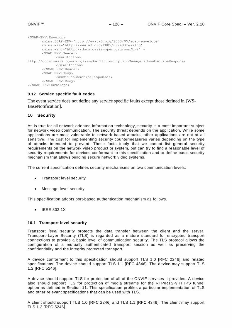
ONVIF™ – 128 – ONVIF Core Spec. – Ver. 2.10 <SOAP-ENV:Envelope xmlns:SOAP-ENV="http://www.w3.org/2003/05/soap-envelope" xmlns:wsa="http://www.w3.org/2005/08/addressing" xmlns:wsnt="http://docs.oasis-open.org/wsn/b-2" > <SOAP-ENV:Header> <wsa:Action> http://docs.oasis-open.org/wsn/bw-2/SubscriptionManager/UnsubscribeResponse </wsa:Action> </SOAP-ENV:Header> <SOAP-ENV:Body> <wsnt:UnsubscribeResponse/> </SOAP-ENV:Body> </SOAP-ENV:Envelope>
9.12 Service specific fault codes
The event service does not define any service specific faults except those defined in [WS-BaseNotification].
10 Security
As is true for all network-oriented information technology, security is a most important subject for network video communication. The security threat depends on the application. While some applications are most vulnerable to network based attacks, other applications are not at all sensitive. The cost for implementing security countermeasures varies depending on the type of attacks intended to prevent. These facts imply that we cannot list general security requirements on the network video product or system, but can try to find a reasonable level of security requirements for devices conformant to this specification and to define basic security mechanism that allows building secure network video systems.
The current specification defines security mechanisms on two communication levels:
Transport level security
Message level security
This specification adopts port-based authentication mechanism as follows.
IEEE 802.1X
10.1 Transport level security
Transport level security protects the data transfer between the client and the server. Transport Layer Security (TLS) is regarded as a mature standard for encrypted transport connections to provide a basic level of communication security. The TLS protocol allows the configuration of a mutually authenticated transport session as well as preserving the confidentiality and the integrity protected transport.
A device conformant to this specification should support TLS 1.0 [RFC 2246] and related specifications. The device should support TLS 1.1 [RFC 4346]. The device may support TLS 1.2 [RFC 5246].
A device should support TLS for protection of all of the ONVIF services it provides. A device also should support TLS for protection of media streams for the RTP/RTSP/HTTPS tunnel option as defined in Section 11. This specification profiles a particular implementation of TLS and other relevant specifications that can be used with TLS.
A client should support TLS 1.0 [RFC 2246] and TLS 1.1 [RFC 4346]. The client may support TLS 1.2 [RFC 5246].
ONVIF™ – 129 – ONVIF Core Spec. – Ver. 2.10 10.1.1 Supported cipher suites
A device that supports TLS shall support all of the following cipher suites [RFC 2246], [RFC 3268]:
TLS_RSA_WITH_AES_128_CBC_SHA
TLS_RSA_WITH_NULL_SHA
If a client supports TLS, then it shall support the following cipher suites:
TLS_RSA_WITH_AES_128_CBC_SHA
TLS_RSA_WITH_NULL_SHA
10.1.2 Server authentication
A device that supports TLS shall support server authentication using TLS. The device shall support processing of X.509 server certificates. The RSA key length shall be at least 1024 bits.
A client should support server authentication using TLS.
This specification does not provide a full server certificate generation and Certificate Authority (CA) model. However, device management commands for device certificate retrieval and download are defined in Section 8.4.
The details of the server private key or keys secure bootstrapping mechanisms are outside the scope of the current specification. However, commands for on board key generation are defined in Section 8.4.
10.1.3 Client authentication
A device that supports TLS should support client authentication. Client authentication can be enabled/disabled with a device management command as described in Section 8.4
A device that supports TLS shall include the RSA certificate type (rsa_sign, for example) in the certificate request [RFC 2246] for client certificates, and shall support verification of the RSA client certificate and signature.
A client should support client authentication. If client authentication is supported, the client shall support RSA client certificate and signature and shall use an RSA key length of at least 1024 bits.
The trusted CA bootstrapping mechanisms are outside the scope of the current specification. Future versions of the specification might define standardized bootstrapping mechanisms.
10.2 Message level security
TLS allows point-to-point confidentiality and integrity. Web Services, however, allow a more flexible communication pattern with intermediate nodes. In such situations TLS cannot provide end-to-end security. Furthermore, in order to implement user based access control on command level for Web Services, there is a need to verify the origin of each SOAP message. How this verification can be implemented is profiled in Section 5.12.
ONVIF™ – 130 – ONVIF Core Spec. – Ver. 2.10
10.3 IEEE 802.1X
IEEE 802.1X is an IEEE standard for port based network access control for the purpose of providing authentication and authorization of the devices attached to LAN ports. It makes use of the physical access characteristics of IEEE 802 LAN infrastructures in order to provide a means of authenticating and authorizing devices attached to a LAN port that has point-to-point connection characteristics, and of preventing access to that port in cases in which the authentication and authorization process fails.
This specification recommends the adoption of IEEE 802.1X for port based authentication for wireless networks. A device that supports IEEE 802.1X shall support EAP-PEAP/MSCHAPv2 type as a supported EAP method. The device may also support other EAP methods such as EAP-MD5, EAP-TLS and EAP-TTLS types.
This specification defines a set of commands to configure and manage the IEEE 802.1X configuration, please refer to section 8.4.7.
ONVIF™ – 131 – ONVIF Core Spec. – Ver. 2.10
Annex A (informative)
Notification topics
A.1 Media configuration topics
For the following entities of the Media Configuration, the ONVIF TopicNamespace provides the following topics:
tns1:MediaConfiguration/Profile tns1:MediaConfiguration/VideoSourceConfiguration tns1:MediaConfiguration/AudioSourceConfiguration tns1:MediaConfiguration/VideoEncoderConfiguration tns1:MediaConfiguration/AudioEncoderConfiguration tns1:MediaConfiguration/VideoAnalyticsConfiguration tns1:MediaConfiguration/PTZConfiguration tns1:MediaConfiguration/MetaDataConfiguration
Each of these topics represents a property. A client subscribing to one of these topics will be notified about changes, creation and deletion of the corresponding entity.
The Message structures of the different topics are specified next using the MessageDescription Language introduced in Section 9.
A.1.1 Profile
<tt:MessageDescription IsProperty="true"> <tt:Source> <tt:SimpleItemDescription Name="ProfileToken" Type="tt:ReferenceToken"/> </tt:Source> <tt:Data> <tt:ElementItemDescription Name="Config" Type="tt:Profile"/> </tt:Data> </tt:MessageDescription>
A.1.2 VideoSourceConfiguration
<tt:MessageDescription IsProperty="true"> <tt:Source> <tt:SimpleItemDescription Name="VideoSourceConfigurationToken" Type="tt:ReferenceToken"/> </tt:Source> <tt:Data> <tt:ElementItemDescription Name="Config" Type="tt:VideoSourceConfiguration"/> </tt:Data> </tt:MessageDescription>
A.1.3 AudioSourceConfiguration
<tt:MessageDescription IsProperty="true"> <tt:Source> <tt:SimpleItemDescription Name="AudioSourceConfigurationToken" Type="tt:ReferenceToken"/> </tt:Source> <tt:Data> <tt:ElementItemDescription Name="Config" Type="tt:AudioSourceConfiguration"/> </tt:Data> </tt:MessageDescription>
ONVIF™ – 132 – ONVIF Core Spec. – Ver. 2.10 A.1.4 VideoEncoderConfiguration
<tt:MessageDescription iIsProperty="true"> <tt:Source> <tt:SimpleItemDescription Name="VideoEncoderConfigurationToken" Type="tt:ReferenceToken"/> </tt:Source> <tt:Data> <tt:ElementItemDescription Name="Config" Type="tt:VideoEncoderConfiguration"/> </tt:Data> </tt:MessageDescription>
A.1.5 AudioEncoderConfiguration
<tt:MessageDescription iIsProperty="true"> <tt:Source> <tt:SimpleItemDescription Name="AudioEncoderConfigurationToken" Type="tt:ReferenceToken"/> </tt:Source> <tt:Data> <tt:ElementItemDescription Name="Config" Type="tt:AudioEncoderConfiguration"/> </tt:Data> </tt:MessageDescription>
A.1.6 VideoAnalyticsConfiguration
<tt:MessageDescription IsProperty="true"> <tt:Source> <tt:SimpleItemDescription Name="VideoAnalyticsConfigurationToken" Type="tt:ReferenceToken"/> </tt:Source> <tt:Data> <tt:ElementItemDescription Name="Config" Type="tt:VideoAnalyticsConfiguration"/> </tt:Data> </tt:MessageDescription>
A.1.7 PTZConfiguration
<tt:MessageDescription IsProperty="true"> <tt:Source> <tt:SimpleItemDescription Name="PTZConfigurationToken" Type="tt:ReferenceToken"/> </tt:Source> <tt:Data> <tt:ElementItemDescription Name="Config" Type="tt:PTZConfiguration"/> </tt:Data> </tt:MessageDescription>
A.1.8 MetaDataConfiguration
<tt:MessageDescription IsProperty="true"> <tt:Source> <tt:SimpleItemDescription Name="MetaDataConfigurationToken" Type="tt:ReferenceToken"/> </tt:Source> <tt:Data> <tt:ElementItemDescription Name="Config" Type="tt:MetaDataConfiguration"/> </tt:Data> </tt:MessageDescription>
A.1.9 Device management topics
The Device Topic contains the following Sub-topics defined in the ONVIF TopicNamespace:
tns1:Device/Trigger/Relay
ONVIF™ – 133 – ONVIF Core Spec. – Ver. 2.10 tns1:Device/OperationMode/ShutdownInitiated tns1:Device/OperationMode/UploadInitiated tns1:Device/HardwareFailure/FanFailure tns1:Device/HardwareFailure/PowerSupplyFailure tns1:Device/HardwareFailure/StorageFailure tns1:Device/HardwareFailure/TemperatureCritical
Only the Relay defines a message payload. The other topics reply with an empty message.
A.1.10 Relay
<tt:MessageDescription IsProperty="true"> <tt:Source> <tt:SimpleItemDescription Name="RelayToken" Type="tt:ReferenceToken"/> </tt:Source> <tt:Data> <tt:SimpleItemDescription Name="LogicalState" Type="tt:RelayLogicalState"/> </tt:Data> </tt:MessageDescription>
A.1.11 PTZ Controller Topics
The PTZ service specifies handling of PTZ presets. Since the move operations are non-blocking, an NVC is not informed when the PTZ preset has been reached. Therefore, the following events are introduced which inform subscribers about the status of preset movements.
tns1:PTZController/PTZPresets/Invoked tns1:PTZController/PTZPresets/Reached tns1:PTZController/PTZPresets/Aborted tns1:PTZController/PTZPresets/Left
The typical sequence of events is that first a NVC requests a certain Preset. When the device accepts this request, it will send out an Invoked event. The Invoked event has to follow either a Reached event or an Aborted event. The former is used when dome was able to reach the invoked preset position, the latter in any other case. A Reached event has to follow a Left event, as soon as the dome moves away from the preset position.
The Message structure of these events is given by the following Message Description (see chapter 12):
<tt:MessageDescription> <tt:Source> <tt:SimpleItemDescription Name="PTZConfigurationToken" Type="tt:ReferenceToken"/> </tt:Source> <tt:Data> <tt:SimpleItemDescription Name="PresetToken" Type="tt:ReferenceToken"/> <tt:SimpleItemDescription Name="PresetName" Type="tt:Name"/> </tt:Data> </tt:MessageDescription>

ONVIF™ – 134 – ONVIF Core Spec. – Ver. 2.10
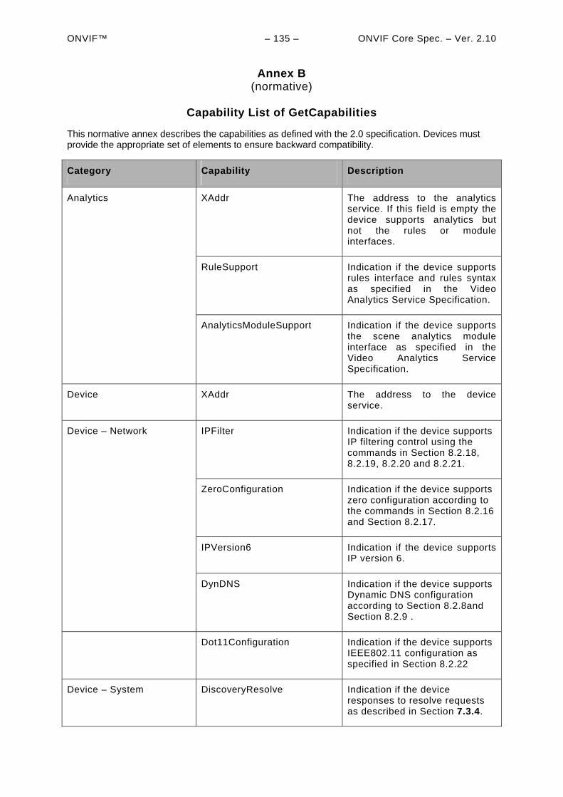
ONVIF™ – 135 – ONVIF Core Spec. – Ver. 2.10
Annex B (normative)
Capability List of GetCapabilities
This normative annex describes the capabilities as defined with the 2.0 specification. Devices must provide the appropriate set of elements to ensure backward compatibility.
Category Capability Description
XAddr The address to the analytics service. If this field is empty the device supports analytics but not the rules or module interfaces.
Analytics
RuleSupport Indication if the device supports rules interface and rules syntax as specified in the Video Analytics Service Specification.
AnalyticsModuleSupport Indication if the device supports the scene analytics module interface as specified in the Video Analytics Service Specification.
Device XAddr The address to the device service.
IPFilter Indication if the device supports IP filtering control using the commands in Section 8.2.18, 8.2.19, 8.2.20 and 8.2.21.
Device – Network
ZeroConfiguration Indication if the device supports zero configuration according to the commands in Section 8.2.16 and Section 8.2.17.
IPVersion6 Indication if the device supports IP version 6.
DynDNS Indication if the device supports Dynamic DNS configuration according to Section 8.2.8and Section 8.2.9 .
Dot11Configuration Indication if the device supports IEEE802.11 configuration as specified in Section 8.2.22
Device – System DiscoveryResolve Indication if the device responses to resolve requests as described in Section 7.3.4.
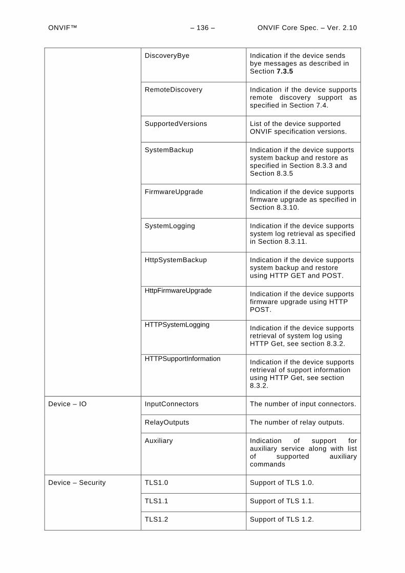
ONVIF™ – 136 – ONVIF Core Spec. – Ver. 2.10
DiscoveryBye Indication if the device sends bye messages as described in Section 7.3.5
RemoteDiscovery Indication if the device supports remote discovery support as specified in Section 7.4.
SupportedVersions List of the device supported ONVIF specification versions.
SystemBackup Indication if the device supports system backup and restore as specified in Section 8.3.3 and Section 8.3.5
FirmwareUpgrade Indication if the device supports firmware upgrade as specified in Section 8.3.10.
SystemLogging Indication if the device supports system log retrieval as specified in Section 8.3.11.
HttpSystemBackup Indication if the device supports system backup and restore using HTTP GET and POST.
HttpFirmwareUpgrade
Indication if the device supports firmware upgrade using HTTP POST.
HTTPSystemLogging Indication if the device supports retrieval of system log using HTTP Get, see section 8.3.2.
HTTPSupportInformation Indication if the device supports retrieval of support information using HTTP Get, see section 8.3.2.
InputConnectors The number of input connectors. Device – IO
RelayOutputs The number of relay outputs.
Auxiliary Indication of support for auxiliary service along with list of supported auxiliary commands
TLS1.0 Support of TLS 1.0. Device – Security
TLS1.1 Support of TLS 1.1.
TLS1.2 Support of TLS 1.2.
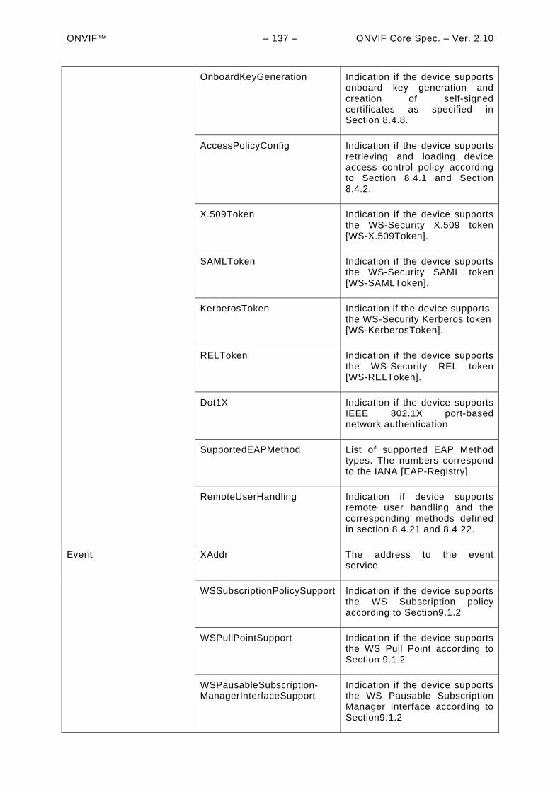
ONVIF™ – 137 – ONVIF Core Spec. – Ver. 2.10
OnboardKeyGeneration Indication if the device supports onboard key generation and creation of self-signed certificates as specified in Section 8.4.8.
AccessPolicyConfig Indication if the device supports retrieving and loading device access control policy according to Section 8.4.1 and Section 8.4.2.
X.509Token Indication if the device supports the WS-Security X.509 token [WS-X.509Token].
SAMLToken Indication if the device supports the WS-Security SAML token [WS-SAMLToken].
KerberosToken Indication if the device supports the WS-Security Kerberos token [WS-KerberosToken].
RELToken Indication if the device supports the WS-Security REL token [WS-RELToken].
Dot1X Indication if the device supports IEEE 802.1X port-based network authentication
SupportedEAPMethod List of supported EAP Method types. The numbers correspond to the IANA [EAP-Registry].
RemoteUserHandling Indication if device supports remote user handling and the corresponding methods defined in section 8.4.21 and 8.4.22.
XAddr The address to the event service
Event
WSSubscriptionPolicySupport Indication if the device supports the WS Subscription policy according to Section9.1.2
WSPullPointSupport Indication if the device supports the WS Pull Point according to Section 9.1.2
WSPausableSubscription-ManagerInterfaceSupport
Indication if the device supports the WS Pausable Subscription Manager Interface according to Section9.1.2
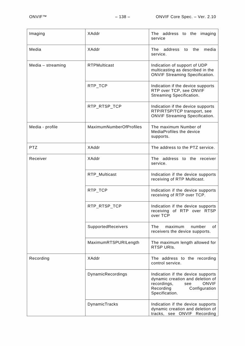
ONVIF™ – 138 – ONVIF Core Spec. – Ver. 2.10
Imaging XAddr The address to the imaging service
Media XAddr The address to the media service.
RTPMulticast Indication of support of UDP multicasting as described in the ONVIF Streaming Specification.
Media – streaming
RTP_TCP Indication if the device supports RTP over TCP, see ONVIF Streaming Specification.
RTP_RTSP_TCP Indication if the device supports RTP/RTSP/TCP transport, see ONVIF Streaming Specification.
Media - profile MaximumNumberOfProfiles The maximum Number of MediaProfiles the device supports.
PTZ XAddr The address to the PTZ service.
XAddr The address to the receiver service.
Receiver
RTP_Multicast Indication if the device supports receiving of RTP Multicast.
RTP_TCP Indication if the device supports receiving of RTP over TCP.
RTP_RTSP_TCP Indication if the device supports receiving of RTP over RTSP over TCP
SupportedReceivers The maximum number of receivers the device supports.
MaximumRTSPURILength The maximum length allowed for RTSP URIs.
XAddr The address to the recording control service.
Recording
DynamicRecordings Indication if the device supports dynamic creation and deletion of recordings, see ONVIF Recording Configuration Specification.
DynamicTracks Indication if the device supports dynamic creation and deletion of tracks, see ONVIF Recording
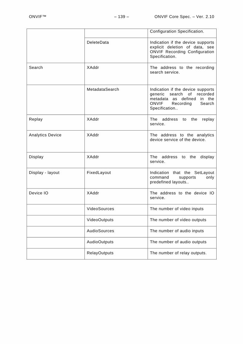
ONVIF™ – 139 – ONVIF Core Spec. – Ver. 2.10
Configuration Specification.
DeleteData Indication if the device supports explicit deletion of data, see ONVIF Recording Configuration Specification.
Search
XAddr The address to the recording search service.
MetadataSearch Indication if the device supports generic search of recorded metadata as defined in the ONVIF Recording Search Specification..
Replay XAddr The address to the replay service.
Analytics Device
XAddr The address to the analytics device service of the device.
Display XAddr The address to the display service.
Display - layout FixedLayout Indication that the SetLayout command supports only predefined layouts..
Device IO XAddr The address to the device IO service.
VideoSources The number of video inputs
VideoOutputs The number of video outputs
AudioSources The number of audio inputs
AudioOutputs The number of audio outputs
RelayOutputs The number of relay outputs.

ONVIF™ – 140 – ONVIF Core Spec. – Ver. 2.10
Bibliography
[EAP-Registry] Extensible Authentication Protocol (EAP) Registry
[http://www.iana.org/assignments/eap-numbers/eap-numbers.xml]
ONVIF Security Recommendations White Paper
[http://www.onvif.org/portals/3/documents/whitepapers/ONVIF_Security_Recommendations_ver10.pdf]
ONVIF PTZ Coordinate Spaces White Paper
[http://www.onvif.org/Portals/0/documents/whitepapers/ONVIF_PTZ_coordinate_spaces.pdf]
RFC 2396, Uniform Resource Identifiers (URI): Generic Syntax, T. Berners-Lee et al., August 1998 [URL:http://www.ietf.org/rfc/rfc2396.txt]
[UDDI API ver2, “UDDI Version 2.04 API Specification UDDI Committee Specification, 19 July 2002”, OASIS standard, 19 July 2002 [URL:http://uddi.org/pubs/ProgrammersAPI-V2.04-Published-20020719.pdf]
[UDDI Data Structure ver2] “UDDI Version 2.03 Data Structure Reference UDDI Committee Specification”, OASIS standard, 19 July 2002.
URL:http://uddi.org/pubs/DataStructure-V2.03-Published-20020719.pdf
[WS-KerberosToken] “Web Services Security Kerberos Token Profile 1.1”, OASIS Standard, ,1 February 2006.
URL:http://www.oasis-open.org/committees/download.php/16788/wss-v1.1-spec-os-KerberosTokenProfile.pdf
[WS-SAMLToken] “Web Services Security: SAML Token Profile 1.1”, OASIS Standard, 1 February 2006.
URL:http://www.oasis-open.org/committees/download.php/16768/wss-v1.1-spec-os-SAMLTokenProfile.pdf
[WS-X.509Token] “Web Services Security X.509 Certificate Token Profile 1.1”, OASIS Standard,1 February 2006.
URL:http://www.oasis-open.org/committees/download.php/16785/wss-v1.1-spec-os-x509TokenProfile.pdf
[WS-RELToken] “Web Services Security Rights Expression Language (REL) Token Profile 1.1”, OASIS Standard, 1 February 2006
URL:http://www.oasis-open.org/committees/download.php/16687/oasis-wss-rel-token-profile-1.1.pdf
[X.680] ITU-T Recommendation X.680 (1997) | ISO/IEC 8824-1:1998, Information
Technology - Abstract Syntax Notation One (ASN.1): Specification of Basic
Notation.
[X.681] ITU-T Recommendation X.681 (1997) | ISO/IEC 8824-2:1998, Information
Technology - Abstract Syntax Notation One (ASN.1): Information Object
Specification.
[X.682] ITU-T Recommendation X.682 (1997) | ISO/IEC 8824-3:1998, Information
Technology - Abstract Syntax Notation One (ASN.1): Constraint Specification.
[X.683] ITU-T Recommendation X.683 (1997) | ISO/IEC 8824-4:1998, Information
Technology - Abstract Syntax Notation One (ASN.1): Parameterization of ASN.1
Specifications.
[X.690] ITU-T Recommendation X.690 (1997) | ISO/IEC 8825-1:1998, Information
Technology - ASN.1 Encoding Rules: Specification of Basic Encoding Rules
(BER), Canonical Encoding Rules (CER) and Distinguished Encoding Rules
(DER).
[ONVIF DM WSDL] ONVIF Device Management Service WSDL, ver 2.1, 2011.
URL:http://www.onvif.org/ver10/device/wsdl/devicemgmt.wsdl
[ONVIF Event WSDL] ONVIF Event Service WSDL, ver 2.1, 2011.
URL:http://www.onvif.org/ver10/event/wsdl/event.wsdl
[ONVIF DP WSDL] ONVIF Remote Discovery Proxy Services WSDL, ver 2.0, 2010.
URL:http://www.onvif.org/ver10/network/wsdl/remotediscovery.wsdl

ONVIF™ – 141 – ONVIF Core Spec. – Ver. 2.10 [ONVIF Schema] ONVIF Schema, ver 2.0, 2010.
URL:http://www.onvif.org/onvif/ver10/schema/onvif.xsd
[ONVIF Topic Namespace] ONVIF Topic Namespace XML, ver 2.0, 2010.
URL:http://www.onvif.org/ver10/topics/topicns.xml
WS-I, Basic Profile Version 2.0 – Working Group Draft, C. Ferris (Ed), A. Karmarkar (Ed) and P. Yendluri (Ed), October 2007.
<http://www.ws-i.org/Profiles/BasicProfile-2_0(WGD).html>