Embed Size (px)
Citation preview
www.rexygen.com
OPC UA server for REXYGENUser guide
REX Controls s.r.o.
Version 2.50.7Plzeň (Pilsen), Czech Republic
2018-03-28

Contents
1 Introduction 31.1 OPC UA . . . . . . . . . . . . . . . . . . . . . . . . . . . . . . . . . . . . 31.2 OPC UA server for REXYGEN . . . . . . . . . . . . . . . . . . . . . . . . . 31.3 Provided functionality . . . . . . . . . . . . . . . . . . . . . . . . . . . . . 4
2 Address space 52.1 Methods . . . . . . . . . . . . . . . . . . . . . . . . . . . . . . . . . . . . . 62.2 Blocks . . . . . . . . . . . . . . . . . . . . . . . . . . . . . . . . . . . . . . 62.3 Parameters . . . . . . . . . . . . . . . . . . . . . . . . . . . . . . . . . . . 62.4 Events . . . . . . . . . . . . . . . . . . . . . . . . . . . . . . . . . . . . . . 7
3 Quick start guide 8
4 Startup and configuration 104.1 Startup . . . . . . . . . . . . . . . . . . . . . . . . . . . . . . . . . . . . . 104.2 System service . . . . . . . . . . . . . . . . . . . . . . . . . . . . . . . . . 104.3 Configuration . . . . . . . . . . . . . . . . . . . . . . . . . . . . . . . . . . 114.4 Configuration sections . . . . . . . . . . . . . . . . . . . . . . . . . . . . . 12
4.4.1 Target . . . . . . . . . . . . . . . . . . . . . . . . . . . . . . . . . . 124.4.2 Application . . . . . . . . . . . . . . . . . . . . . . . . . . . . . . . 134.4.3 Security . . . . . . . . . . . . . . . . . . . . . . . . . . . . . . . . . 144.4.4 Auth . . . . . . . . . . . . . . . . . . . . . . . . . . . . . . . . . . . 154.4.5 Endpoint . . . . . . . . . . . . . . . . . . . . . . . . . . . . . . . . 164.4.6 Discovery . . . . . . . . . . . . . . . . . . . . . . . . . . . . . . . . 174.4.7 Options . . . . . . . . . . . . . . . . . . . . . . . . . . . . . . . . . 18
4.5 Configuration templates . . . . . . . . . . . . . . . . . . . . . . . . . . . . 21
5 Authentication and authorization 225.1 Roles and users . . . . . . . . . . . . . . . . . . . . . . . . . . . . . . . . . 225.2 User administration . . . . . . . . . . . . . . . . . . . . . . . . . . . . . . 22
6 Configuration Tool 246.1 Certificates . . . . . . . . . . . . . . . . . . . . . . . . . . . . . . . . . . . 256.2 Authentication . . . . . . . . . . . . . . . . . . . . . . . . . . . . . . . . . 27
1

6.3 Configuration examples . . . . . . . . . . . . . . . . . . . . . . . . . . . . 29
7 Connection testing with OPC UA clients 317.1 UaExpert . . . . . . . . . . . . . . . . . . . . . . . . . . . . . . . . . . . . 337.2 myScada . . . . . . . . . . . . . . . . . . . . . . . . . . . . . . . . . . . . . 43
Bibliography 48
2
Chapter 1
Introduction
1.1 OPC UA
OPC UA is an open communication protocol for industrial automation. Unlike legacyOPC, OPC UA is a multi-platform protocol, it may work as a web service and it offersmany advanced functions like diagnostics, method calls and various levels of security andauthentication in addition to standard events and data access. OPC UA is becoming apreferred communication interface of many devices from various companies.
However, OPC UA is not a suitable protocol for hard real-time communication be-tween control devices, but is sufficient for soft real-time applications in many cases. Amain utilization areas of OPC UA are human-machine interfaces and interconnection ofvarious devices in a heterogeneous environment.
1.2 OPC UA server for REXYGEN
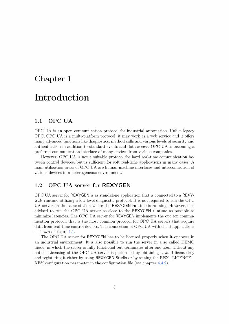
OPC UA server for REXYGEN is as standalone application that is connected to a REXY-GEN runtime utilizing a low-level diagnostic protocol. It is not required to run the OPCUA server on the same station where the REXYGEN runtime is running. However, it isadvised to run the OPC UA server as close to the REXYGEN runtime as possible tominimize latencies. The OPC UA server for REXYGEN implements the opc.tcp commu-nication protocol, that is the most common protocol for OPC UA servers that acquiredata from real-time control devices. The connection of OPC UA with client applicationsis shown on figure 1.1.
The OPC UA server for REXYGEN has to be licensed properly when it operates inan industrial environment. It is also possible to run the server in a so called DEMOmode, in which the server is fully functional but terminates after one hour without anynotice. Licensing of the OPC UA server is performed by obtaining a valid license keyand registering it either by using REXYGEN Studio or by setting the REX_LICENCE_KEY configuration parameter in the configuration file (see chapter 4.4.2).
3
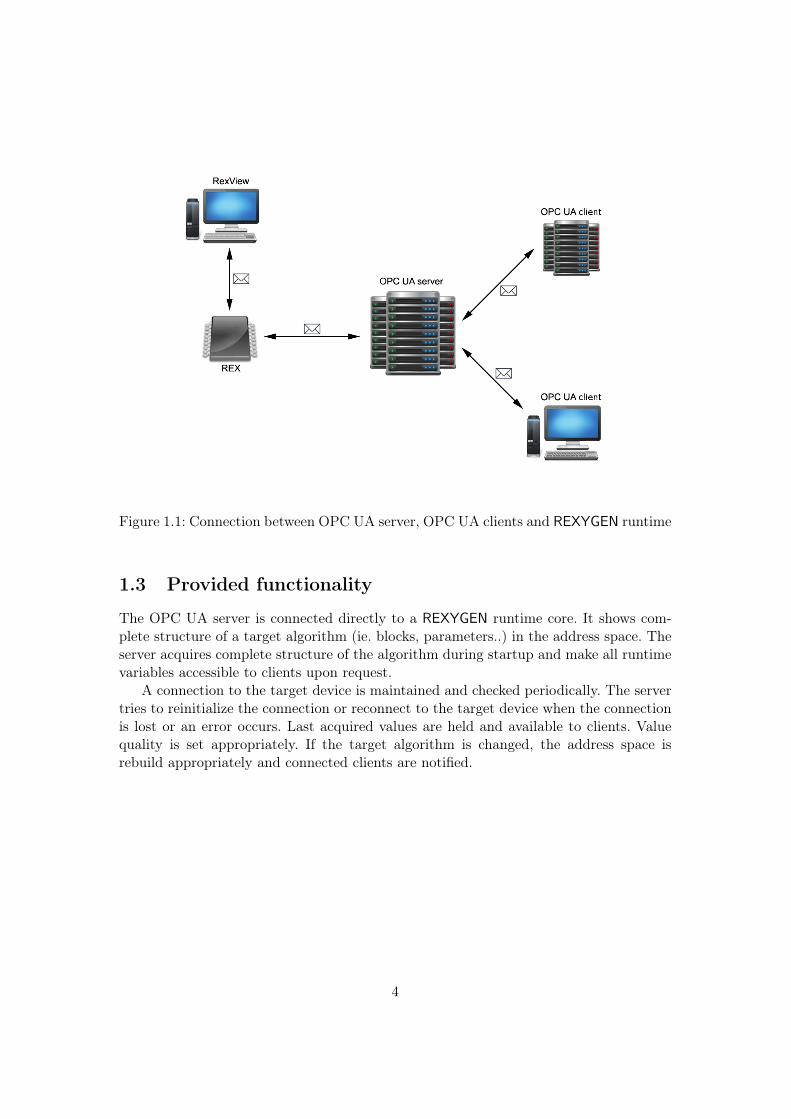
Figure 1.1: Connection between OPC UA server, OPC UA clients and REXYGEN runtime
1.3 Provided functionality
The OPC UA server is connected directly to a REXYGEN runtime core. It shows com-plete structure of a target algorithm (ie. blocks, parameters..) in the address space. Theserver acquires complete structure of the algorithm during startup and make all runtimevariables accessible to clients upon request.
A connection to the target device is maintained and checked periodically. The servertries to reinitialize the connection or reconnect to the target device when the connectionis lost or an error occurs. Last acquired values are held and available to clients. Valuequality is set appropriately. If the target algorithm is changed, the address space isrebuild appropriately and connected clients are notified.
4
Chapter 2
Address space
An address space contains all the data that is available to clients. Address space iscomprised of nodes. Some nodes are common to all OPC UA servers, other nodes areapplication-specific. There are also nodes that control the server itself. The "Exec" nodeis a root node to all runtime-specific variables and the whole structure of a target algo-rithm (ie. tasks, subsystems, blocks and parameters) is available underneath this node.A content of the "Exec" node is rebuilt when a connection with a target is established ora control algorithm is changed on the target. A sample address space is shown on figure2.1. The picture has been taken from UaExpert OPC UA client (see chapter 7.1).
Figure 2.1: Address space in UaExpert
5
The server utilizes several name spaces. The first name space corresponds to theapplication URI and is dedicated for a server diagnostics.
The name space urn:Rex:TypeDeclaration is dedicated for definitions of types thatare used among the address space.
The name space urn:Rex:Server is dedicated for commanding the server itself.A name space that corresponds to the target algorithm is always target-specific and
is described in chapter 4.4.2. This name space contains are all nodes that corresponds tothe target algorithm.
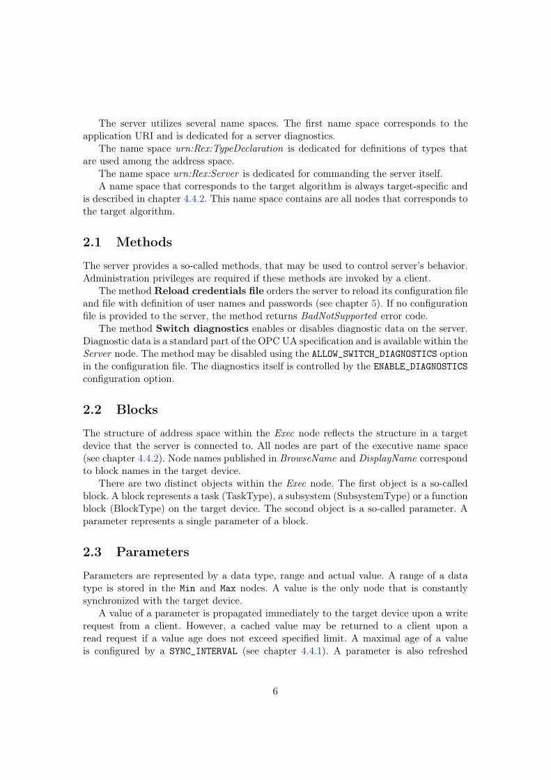
2.1 Methods
The server provides a so-called methods, that may be used to control server’s behavior.Administration privileges are required if these methods are invoked by a client.
The method Reload credentials file orders the server to reload its configuration fileand file with definition of user names and passwords (see chapter 5). If no configurationfile is provided to the server, the method returns BadNotSupported error code.
The method Switch diagnostics enables or disables diagnostic data on the server.Diagnostic data is a standard part of the OPC UA specification and is available within theServer node. The method may be disabled using the ALLOW_SWITCH_DIAGNOSTICS optionin the configuration file. The diagnostics itself is controlled by the ENABLE_DIAGNOSTICS
configuration option.
2.2 Blocks
The structure of address space within the Exec node reflects the structure in a targetdevice that the server is connected to. All nodes are part of the executive name space(see chapter 4.4.2). Node names published in BrowseName and DisplayName correspondto block names in the target device.
There are two distinct objects within the Exec node. The first object is a so-calledblock. A block represents a task (TaskType), a subsystem (SubsystemType) or a functionblock (BlockType) on the target device. The second object is a so-called parameter. Aparameter represents a single parameter of a block.
2.3 Parameters
Parameters are represented by a data type, range and actual value. A range of a datatype is stored in the Min and Max nodes. A value is the only node that is constantlysynchronized with the target device.
A value of a parameter is propagated immediately to the target device upon a writerequest from a client. However, a cached value may be returned to a client upon aread request if a value age does not exceed specified limit. A maximal age of a valueis configured by a SYNC_INTERVAL (see chapter 4.4.1). A parameter is also refreshed
6
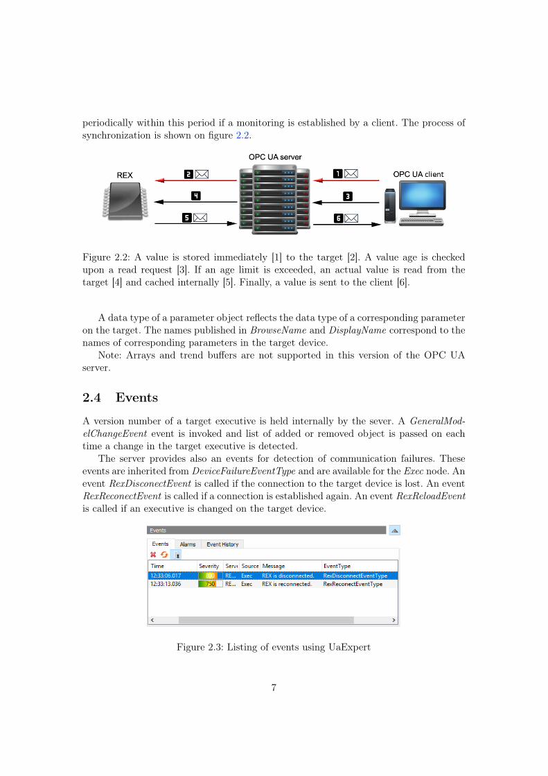
periodically within this period if a monitoring is established by a client. The process ofsynchronization is shown on figure 2.2.
Figure 2.2: A value is stored immediately [1] to the target [2]. A value age is checkedupon a read request [3]. If an age limit is exceeded, an actual value is read from thetarget [4] and cached internally [5]. Finally, a value is sent to the client [6].
A data type of a parameter object reflects the data type of a corresponding parameteron the target. The names published in BrowseName and DisplayName correspond to thenames of corresponding parameters in the target device.
Note: Arrays and trend buffers are not supported in this version of the OPC UAserver.
2.4 Events
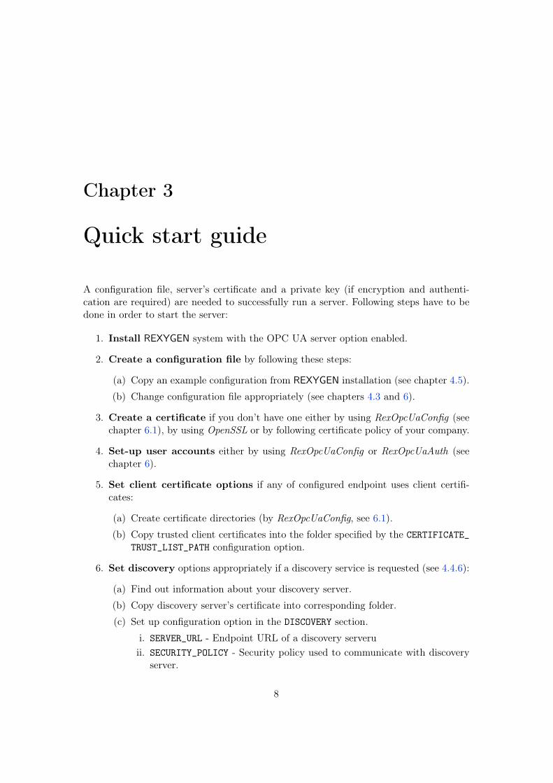
A version number of a target executive is held internally by the sever. A GeneralMod-elChangeEvent event is invoked and list of added or removed object is passed on eachtime a change in the target executive is detected.
The server provides also an events for detection of communication failures. Theseevents are inherited from DeviceFailureEventType and are available for the Exec node. Anevent RexDisconectEvent is called if the connection to the target device is lost. An eventRexReconectEvent is called if a connection is established again. An event RexReloadEventis called if an executive is changed on the target device.
Figure 2.3: Listing of events using UaExpert
7
Chapter 3
Quick start guide
A configuration file, server’s certificate and a private key (if encryption and authenti-cation are required) are needed to successfully run a server. Following steps have to bedone in order to start the server:
1. Install REXYGEN system with the OPC UA server option enabled.
2. Create a configuration file by following these steps:
(a) Copy an example configuration from REXYGEN installation (see chapter 4.5).
(b) Change configuration file appropriately (see chapters 4.3 and 6).
3. Create a certificate if you don’t have one either by using RexOpcUaConfig (seechapter 6.1), by using OpenSSL or by following certificate policy of your company.
4. Set-up user accounts either by using RexOpcUaConfig or RexOpcUaAuth (seechapter 6).
5. Set client certificate options if any of configured endpoint uses client certifi-cates:
(a) Create certificate directories (by RexOpcUaConfig, see 6.1).
(b) Copy trusted client certificates into the folder specified by the CERTIFICATE_
TRUST_LIST_PATH configuration option.
6. Set discovery options appropriately if a discovery service is requested (see 4.4.6):
(a) Find out information about your discovery server.
(b) Copy discovery server’s certificate into corresponding folder.
(c) Set up configuration option in the DISCOVERY section.
i. SERVER_URL - Endpoint URL of a discovery serveruii. SECURITY_POLICY - Security policy used to communicate with discovery
server.
8

iii. SERVER_CERTIFICATE_PATH - A patch to a certificate of a discovery server.iv. ENDPOINT_URL - Endpoint list that is to be published on a discovery server.
A single endpoint should be sufficient to register OPC UA server properly.
7. Run the OPC UA service, see chapter 4.2.
9
Chapter 4
Startup and configuration
4.1 Startup
The server is configured by a simple configuration file. Its location is specified by the"-c" parameter.
RexOpcUa [-c <configFile>]
Path to the configuration file is set by default in GNU/Linux:
/rex/OpcUa/RexOpcUa.ini
Configuration options are described in chapter 4. The server may also run as a systemservice – see chapter 4.2). A quick start guide is available in chapter 3.
4.2 System service
The OPC UA server may run as a system service. The system service mode is a defaultand a recommended mode.
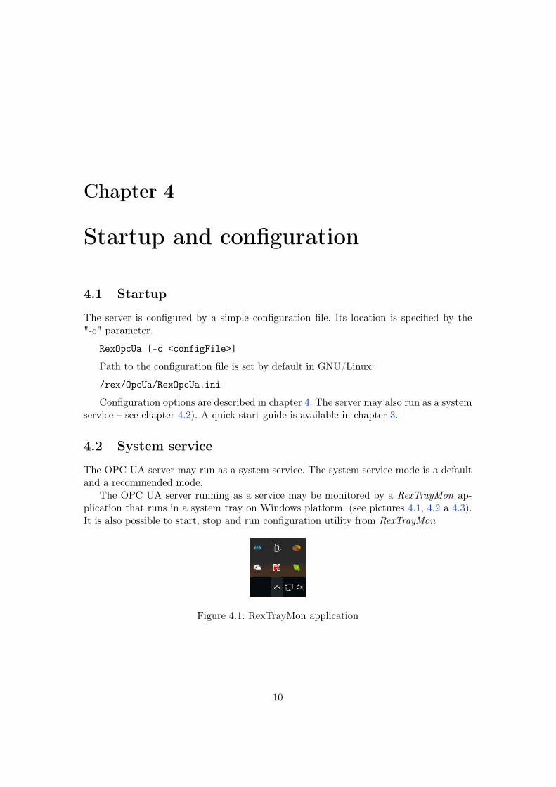
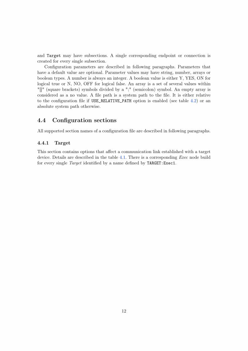
The OPC UA server running as a service may be monitored by a RexTrayMon ap-plication that runs in a system tray on Windows platform. (see pictures 4.1, 4.2 a 4.3).It is also possible to start, stop and run configuration utility from RexTrayMon
Figure 4.1: RexTrayMon application
10
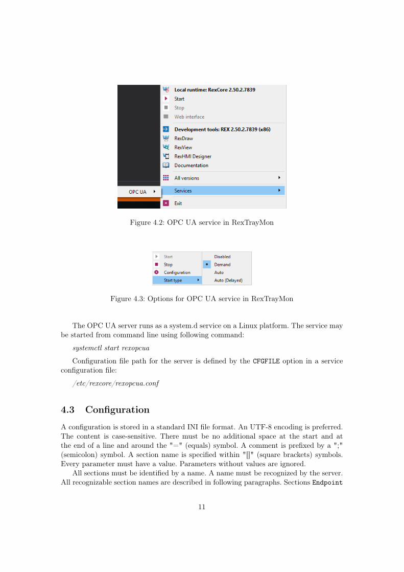
Figure 4.2: OPC UA service in RexTrayMon
Figure 4.3: Options for OPC UA service in RexTrayMon
The OPC UA server runs as a system.d service on a Linux platform. The service maybe started from command line using following command:
systemctl start rexopcua
Configuration file path for the server is defined by the CFGFILE option in a serviceconfiguration file:
/etc/rexcore/rexopcua.conf
4.3 Configuration
A configuration is stored in a standard INI file format. An UTF-8 encoding is preferred.The content is case-sensitive. There must be no additional space at the start and atthe end of a line and around the "=" (equals) symbol. A comment is prefixed by a ";"(semicolon) symbol. A section name is specified within "[]" (square brackets) symbols.Every parameter must have a value. Parameters without values are ignored.
All sections must be identified by a name. A name must be recognized by the server.All recognizable section names are described in following paragraphs. Sections Endpoint
11
and Target may have subsections. A single corresponding endpoint or connection iscreated for every single subsection.
Configuration parameters are described in following paragraphs. Parameters thathave a default value are optional. Parameter values may have string, number, arrays orboolean types. A number is always an integer. A boolean value is either Y, YES, ON forlogical true or N, NO, OFF for logical false. An array is a set of several values within"[]" (square brackets) symbols divided by a ";" (semicolon) symbol. An empty array isconsidered as a no value. A file path is a system path to the file. It is either relativeto the configuration file if USE_RELATIVE_PATH option is enabled (see table 4.2) or anabsolute system path otherwise.
4.4 Configuration sections
All supported section names of a configuration file are described in following paragraphs.
4.4.1 Target
This section contains options that affect a communication link established with a targetdevice. Details are described in the table 4.1. There is a corresponding Exec node buildfor every single Target identified by a name defined by TARGET:Exec1.
12
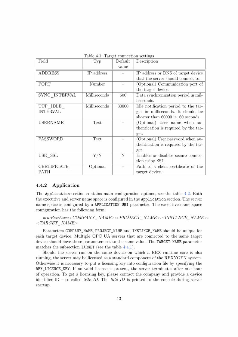
Table 4.1: Target connection settingsField Typ Default
valueDescription
ADDRESS IP address – IP address or DNS of target devicethat the server should connect to.
PORT Number – (Optional) Communication port ofthe target device.
SYNC_INTERVAL Milliseconds 500 Data synchronization period in mil-liseconds.
TCP_IDLE_INTERVAL
Milliseconds 30000 Idle notification period to the tar-get in milliseconds. It should beshorter than 60000 ie. 60 seconds.
USERNAME Text – (Optional) User name when au-thentication is required by the tar-get.
PASSWORD Text – (Optional) User password when au-thentication is required by the tar-get.
USE_SSL Y/N N Enables or disables secure connec-tion using SSL.
CERTIFICATE_PATH
Optional – Path to a client certificate of thetarget device.
4.4.2 Application
The Application section contains main configuration options, see the table 4.2. Boththe executive and server name space is configured in the Application section. The servername space is configured by a APPLICATION_URI parameter. The executive name spaceconfiguration has the following form:
urn:Rex:Exec:<COMPANY_NAME>:<PROJECT_NAME>:<INSTANCE_NAME>:<TARGET_NAME>
Parameters COMPANY_NAME, PROJECT_NAME and INSTANCE_NAME should be unique foreach target device. Multiple OPC UA servers that are connected to the same targetdevice should have these parameters set to the same value. The TARGET_NAME parametermatches the subsection TARGET (see the table 4.4.1).
Should the server run on the same device on which a REX runtime core is alsorunning, the server may be licensed as a standard component of the REXYGEN system.Otherwise it is necessary to put a licensing key into configuration file by specifying theREX_LICENCE_KEY. If no valid license is present, the server terminates after one hourof operation. To get a licensing key, please contact the company and provide a deviceidentifier ID – so-called Site ID. The Site ID is printed to the console during serverstartup.
13
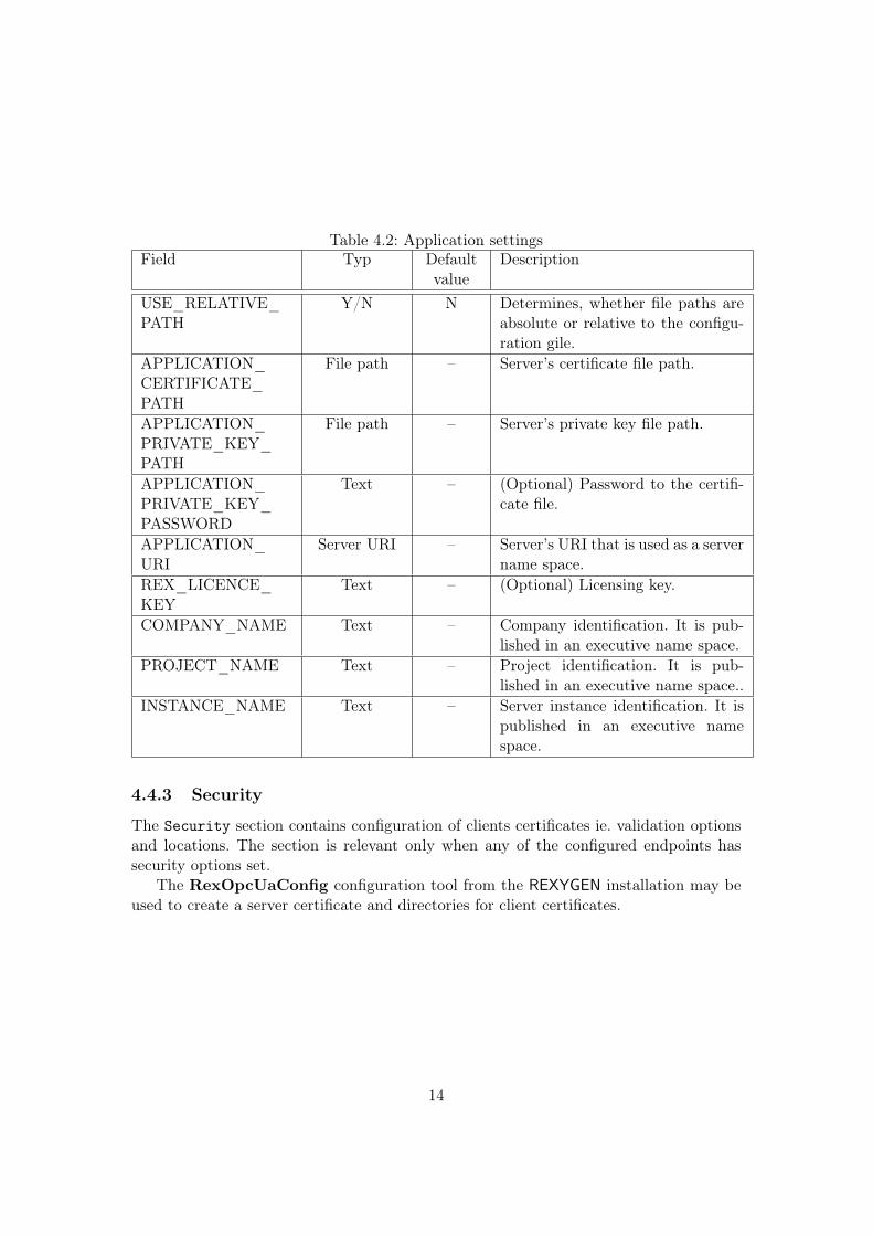
Table 4.2: Application settingsField Typ Default
valueDescription
USE_RELATIVE_PATH
Y/N N Determines, whether file paths areabsolute or relative to the configu-ration gile.
APPLICATION_CERTIFICATE_PATH
File path – Server’s certificate file path.
APPLICATION_PRIVATE_KEY_PATH
File path – Server’s private key file path.
APPLICATION_PRIVATE_KEY_PASSWORD
Text – (Optional) Password to the certifi-cate file.
APPLICATION_URI
Server URI – Server’s URI that is used as a servername space.
REX_LICENCE_KEY
Text – (Optional) Licensing key.
COMPANY_NAME Text – Company identification. It is pub-lished in an executive name space.
PROJECT_NAME Text – Project identification. It is pub-lished in an executive name space..
INSTANCE_NAME Text – Server instance identification. It ispublished in an executive namespace.
4.4.3 Security
The Security section contains configuration of clients certificates ie. validation optionsand locations. The section is relevant only when any of the configured endpoints hassecurity options set.
The RexOpcUaConfig configuration tool from the REXYGEN installation may beused to create a server certificate and directories for client certificates.
14
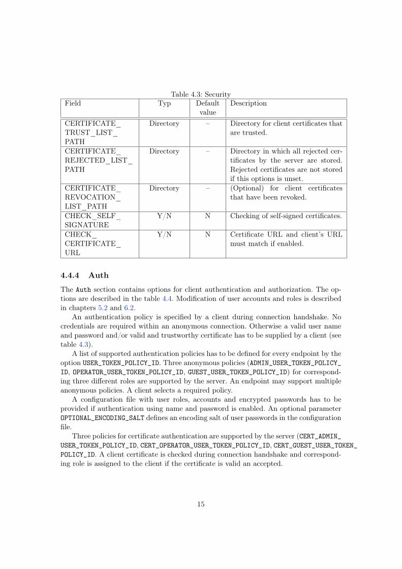
Table 4.3: SecurityField Typ Default
valueDescription
CERTIFICATE_TRUST_LIST_PATH
Directory – Directory for client certificates thatare trusted.
CERTIFICATE_REJECTED_LIST_PATH
Directory – Directory in which all rejected cer-tificates by the server are stored.Rejected certificates are not storedif this options is unset.
CERTIFICATE_REVOCATION_LIST_PATH
Directory – (Optional) for client certificatesthat have been revoked.
CHECK_SELF_SIGNATURE
Y/N N Checking of self-signed certificates.
CHECK_CERTIFICATE_URL
Y/N N Certificate URL and client’s URLmust match if enabled.
4.4.4 Auth
The Auth section contains options for client authentication and authorization. The op-tions are described in the table 4.4. Modification of user accounts and roles is describedin chapters 5.2 and 6.2.
An authentication policy is specified by a client during connection handshake. Nocredentials are required within an anonymous connection. Otherwise a valid user nameand password and/or valid and trustworthy certificate has to be supplied by a client (seetable 4.3).
A list of supported authentication policies has to be defined for every endpoint by theoption USER_TOKEN_POLICY_ID. Three anonymous policies (ADMIN_USER_TOKEN_POLICY_ID, OPERATOR_USER_TOKEN_POLICY_ID, GUEST_USER_TOKEN_POLICY_ID) for correspond-ing three different roles are supported by the server. An endpoint may support multipleanonymous policies. A client selects a required policy.
A configuration file with user roles, accounts and encrypted passwords has to beprovided if authentication using name and password is enabled. An optional parameterOPTIONAL_ENCODING_SALT defines an encoding salt of user passwords in the configurationfile.
Three policies for certificate authentication are supported by the server (CERT_ADMIN_USER_TOKEN_POLICY_ID, CERT_OPERATOR_USER_TOKEN_POLICY_ID, CERT_GUEST_USER_TOKEN_POLICY_ID. A client certificate is checked during connection handshake and correspond-ing role is assigned to the client if the certificate is valid an accepted.
15
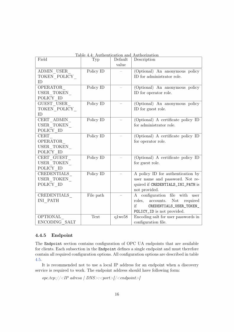
Table 4.4: Authentication and AuthorizationField Typ Default
valueDescription
ADMIN_USER_TOKEN_POLICY_ID
Policy ID – (Optional) An anonymous policyID for administrator role.
OPERATOR_USER_TOKEN_POLICY_ID
Policy ID – (Optional) An anonymous policyID for operator role.
GUEST_USER_TOKEN_POLICY_ID
Policy ID – (Optional) An anonymous policyID for guest role.
CERT_ADMIN_USER_TOKEN_POLICY_ID
Policy ID – (Optional) A certificate policy IDfor administrator role.
CERT_OPERATOR_USER_TOKEN_POLICY_ID
Policy ID – (Optional) A certificate policy IDfor operator role.
CERT_GUEST_USER_TOKEN_POLICY_ID
Policy ID – (Optional) A certificate policy IDfor guest role.
CREDENTIALS_USER_TOKEN_POLICY_ID
Policy ID – A policy ID for authentication byuser name and password. Not re-quired if CREDENTIALS_INI_PATH isnot provided.
CREDENTIALS_INI_PATH
File path – A configuration file with userroles, accounts. Not requiredif CREDENTIALS_USER_TOKEN_
POLICY_ID is not provided.OPTIONAL_ENCODING_SALT
Text q1we58 Encoding salt for user passwords inconfiguration file.
4.4.5 Endpoint
The Endpoint section contains configuration of OPC UA endpoints that are availablefor clients. Each subsection in the Endpoint defines a single endpoint and must thereforecontain all required configuration options. All configuration options are described in table4.5.
It is recommended not to use a local IP address for an endpoint when a discoveryservice is required to work. The endpoint address should have following form:
opc.tcp://<IP adresa | DNS>:<port>[/<endpoint>]
16
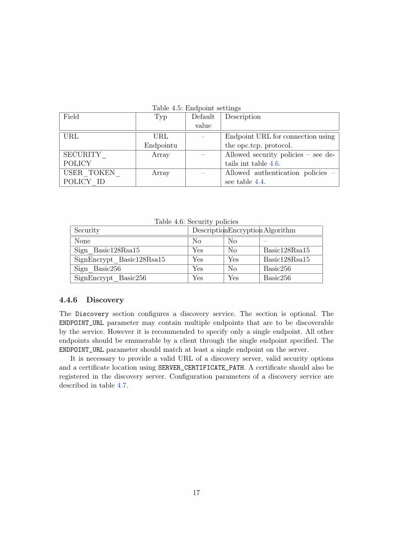
Table 4.5: Endpoint settingsField Typ Default
valueDescription
URL URLEndpointu
– Endpoint URL for connection usingthe opc.tcp. protocol.
SECURITY_POLICY
Array – Allowed security policies – see de-tails int table 4.6.
USER_TOKEN_POLICY_ID
Array – Allowed authentication policies –see table 4.4.
Table 4.6: Security policiesSecurity DescriptionEncryptionAlgorithmNone No No –Sign_Basic128Rsa15 Yes No Basic128Rsa15SignEncrypt_Basic128Rsa15 Yes Yes Basic128Rsa15Sign_Basic256 Yes No Basic256SignEncrypt_Basic256 Yes Yes Basic256
4.4.6 Discovery
The Discovery section configures a discovery service. The section is optional. TheENDPOINT_URL parameter may contain multiple endpoints that are to be discoverableby the service. However it is recommended to specify only a single endpoint. All otherendpoints should be enumerable by a client through the single endpoint specified. TheENDPOINT_URL parameter should match at least a single endpoint on the server.
It is necessary to provide a valid URL of a discovery server, valid security optionsand a certificate location using SERVER_CERTIFICATE_PATH. A certificate should also beregistered in the discovery server. Configuration parameters of a discovery service aredescribed in table 4.7.
17
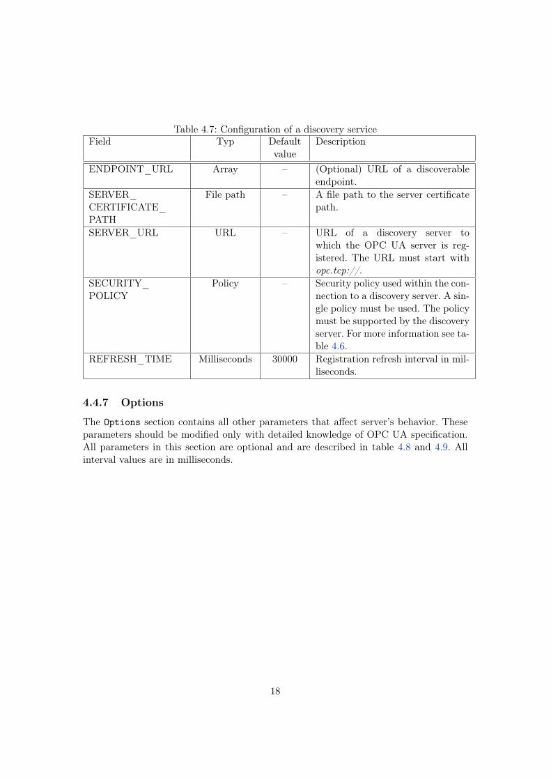
Table 4.7: Configuration of a discovery serviceField Typ Default
valueDescription
ENDPOINT_URL Array – (Optional) URL of a discoverableendpoint.
SERVER_CERTIFICATE_PATH
File path – A file path to the server certificatepath.
SERVER_URL URL – URL of a discovery server towhich the OPC UA server is reg-istered. The URL must start withopc.tcp://.
SECURITY_POLICY
Policy – Security policy used within the con-nection to a discovery server. A sin-gle policy must be used. The policymust be supported by the discoveryserver. For more information see ta-ble 4.6.
REFRESH_TIME Milliseconds 30000 Registration refresh interval in mil-liseconds.
4.4.7 Options
The Options section contains all other parameters that affect server’s behavior. Theseparameters should be modified only with detailed knowledge of OPC UA specification.All parameters in this section are optional and are described in table 4.8 and 4.9. Allinterval values are in milliseconds.
18
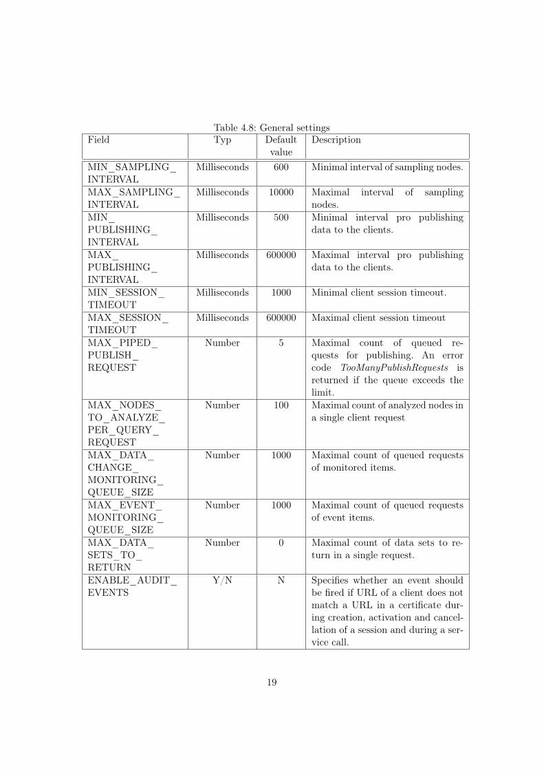
Table 4.8: General settingsField Typ Default
valueDescription
MIN_SAMPLING_INTERVAL
Milliseconds 600 Minimal interval of sampling nodes.
MAX_SAMPLING_INTERVAL
Milliseconds 10000 Maximal interval of samplingnodes.
MIN_PUBLISHING_INTERVAL
Milliseconds 500 Minimal interval pro publishingdata to the clients.
MAX_PUBLISHING_INTERVAL
Milliseconds 600000 Maximal interval pro publishingdata to the clients.
MIN_SESSION_TIMEOUT
Milliseconds 1000 Minimal client session timeout.
MAX_SESSION_TIMEOUT
Milliseconds 600000 Maximal client session timeout
MAX_PIPED_PUBLISH_REQUEST
Number 5 Maximal count of queued re-quests for publishing. An errorcode TooManyPublishRequests isreturned if the queue exceeds thelimit.
MAX_NODES_TO_ANALYZE_PER_QUERY_REQUEST
Number 100 Maximal count of analyzed nodes ina single client request
MAX_DATA_CHANGE_MONITORING_QUEUE_SIZE
Number 1000 Maximal count of queued requestsof monitored items.
MAX_EVENT_MONITORING_QUEUE_SIZE
Number 1000 Maximal count of queued requestsof event items.
MAX_DATA_SETS_TO_RETURN
Number 0 Maximal count of data sets to re-turn in a single request.
ENABLE_AUDIT_EVENTS
Y/N N Specifies whether an event shouldbe fired if URL of a client does notmatch a URL in a certificate dur-ing creation, activation and cancel-lation of a session and during a ser-vice call.
19
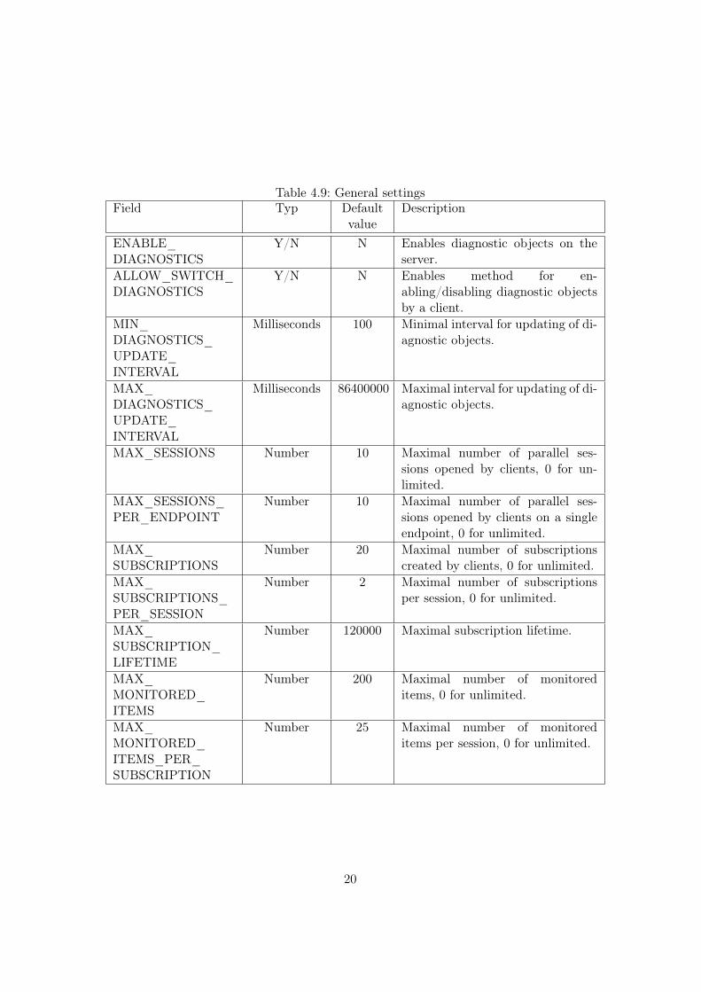
Table 4.9: General settingsField Typ Default
valueDescription
ENABLE_DIAGNOSTICS
Y/N N Enables diagnostic objects on theserver.
ALLOW_SWITCH_DIAGNOSTICS
Y/N N Enables method for en-abling/disabling diagnostic objectsby a client.
MIN_DIAGNOSTICS_UPDATE_INTERVAL
Milliseconds 100 Minimal interval for updating of di-agnostic objects.
MAX_DIAGNOSTICS_UPDATE_INTERVAL
Milliseconds 86400000 Maximal interval for updating of di-agnostic objects.
MAX_SESSIONS Number 10 Maximal number of parallel ses-sions opened by clients, 0 for un-limited.
MAX_SESSIONS_PER_ENDPOINT
Number 10 Maximal number of parallel ses-sions opened by clients on a singleendpoint, 0 for unlimited.
MAX_SUBSCRIPTIONS
Number 20 Maximal number of subscriptionscreated by clients, 0 for unlimited.
MAX_SUBSCRIPTIONS_PER_SESSION
Number 2 Maximal number of subscriptionsper session, 0 for unlimited.
MAX_SUBSCRIPTION_LIFETIME
Number 120000 Maximal subscription lifetime.
MAX_MONITORED_ITEMS
Number 200 Maximal number of monitoreditems, 0 for unlimited.
MAX_MONITORED_ITEMS_PER_SUBSCRIPTION
Number 25 Maximal number of monitoreditems per session, 0 for unlimited.
20
4.5 Configuration templates
Several configuration templates are provided to make it easier to configure a new instanceof the OPC UA server. These configurations may be used as a quick start templates forarbitrary configurations. Following configuration templates are provided:
• MINIMAL - a minimal configuration with and unsecured endpoint and a runningREXYGEN target on localhost,
• ENDPOINTS - a configuration with two endpoints,
• LICENCE - a configuration with defined licensing key,
• SECURITY - a configuration for secured endpoints without authentication,
• PASS_AUTH - a configuration for secured endpoints and authentication with username and password,
• CERT_AUTH - a configuration for secured endpoints and authentication with clientcertificates,
• DISCOVERY - a configuration with registration to a discovery server,
• FULL - a complete configuration.
It is recommended to always modify parameters ADDRESS, COMPANY_NAME, PROJECT_NAME and INSTANCE_NAME.
21

Chapter 5
Authentication and authorization
5.1 Roles and users
Three roles are defined in the OPC UA server: guest, operator and administrator. Aguest is allowed to browse address space and read values of parameters and block. Anoperator has all the permissions that a guest have and is also allowed to write values ofparameters and blocks and thus affect behavior of a target algorithm. An administratorhas unlimited permissions including invocation of server methods and so affect behaviorof the OPC UA server itself, see chapter 2.1. Access permissions are listed in table 5.1.
Table 5.1: PermissionsPermission Admin Operator GuestReading values X X XWriting values X XMethod invocation X
A role that si applied for a session is determined by a security policy that is appliedon an endpoint and during authentication process. A client may only apply policies thatare enabled and allowed on an endpoint. Security, authentication and authorization isensured by a configuration of policies for endpoints, see chapter 4.4.5.
A valid path to a configuration file with roles, users and passwords has to be pro-vided when authentication using user name and password is enabled. The configurationfile is loaded during the server startup or when a method ReloadAuth is invoked. UseRexOpcUaAuth or RexOpcUaConfig tools to modify user accounts. These tools areintegral part of REXYGEN installation.
5.2 User administration
The RexOpcUaAuth is a command line tool that allows modification of user accountsin a configuration file. Command arguments have following sytax:
22
RexOpcUaAuth <configFile> -l
Lists all users and their roles.
RexOpcUaAuth <configFile> -c <username> <password> <role>
Creates a new user with a password and a role assigned. Allowed roles are admin, operatorand guest.
RexOpcUaAuth <configFile> -p <username> <password>
Changes user password.
RexOpcUaAuth <configFile> -a <username> <role>
Changes user role.
RexOpcUaAuth <configFile> -r <username> <new_username>
Changes user name.
RexOpcUaAuth <configFile> -d <username>
Deletes a user.
A path to the use configuration path has to be specified using the CREDENTIALS_INI_PATH in the main configuration file.
Note: If a user configuration file is missing, lost or damaged, just create an emptyfile and define user accounts using the tool.
23
Chapter 6
Configuration Tool
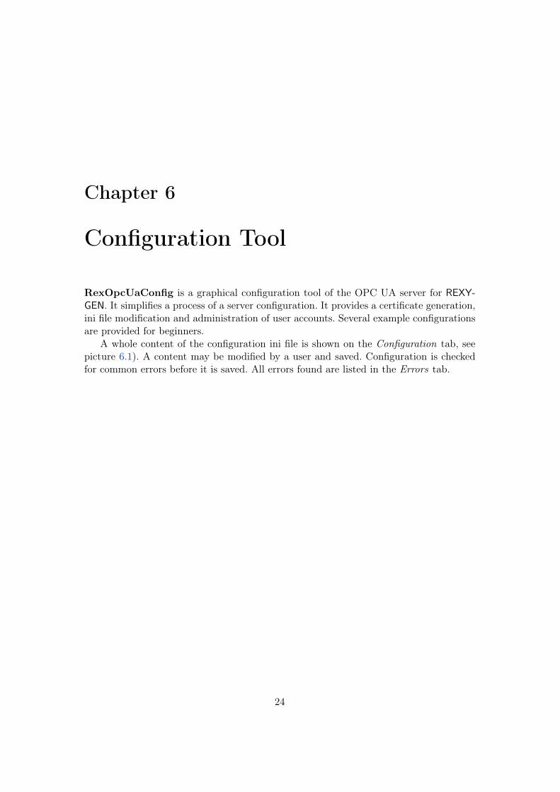
RexOpcUaConfig is a graphical configuration tool of the OPC UA server for REXY-GEN. It simplifies a process of a server configuration. It provides a certificate generation,ini file modification and administration of user accounts. Several example configurationsare provided for beginners.
A whole content of the configuration ini file is shown on the Configuration tab, seepicture 6.1). A content may be modified by a user and saved. Configuration is checkedfor common errors before it is saved. All errors found are listed in the Errors tab.
24
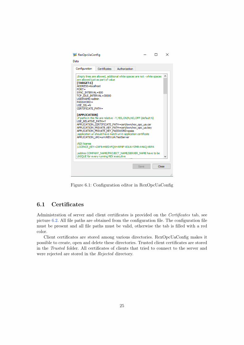
Figure 6.1: Configuration editor in RexOpcUaConfig
6.1 Certificates
Administration of server and client certificates is provided on the Certificates tab, seepicture 6.2. All file paths are obtained from the configuration file. The configuration filemust be present and all file paths must be valid, otherwise the tab is filled with a redcolor.
Client certificates are stored among various directories. RexOpcUaConfig makes itpossible to create, open and delete these directories. Trusted client certificates are storedin the Trusted folder. All certificates of clients that tried to connect to the server andwere rejected are stored in the Rejected directory.
25
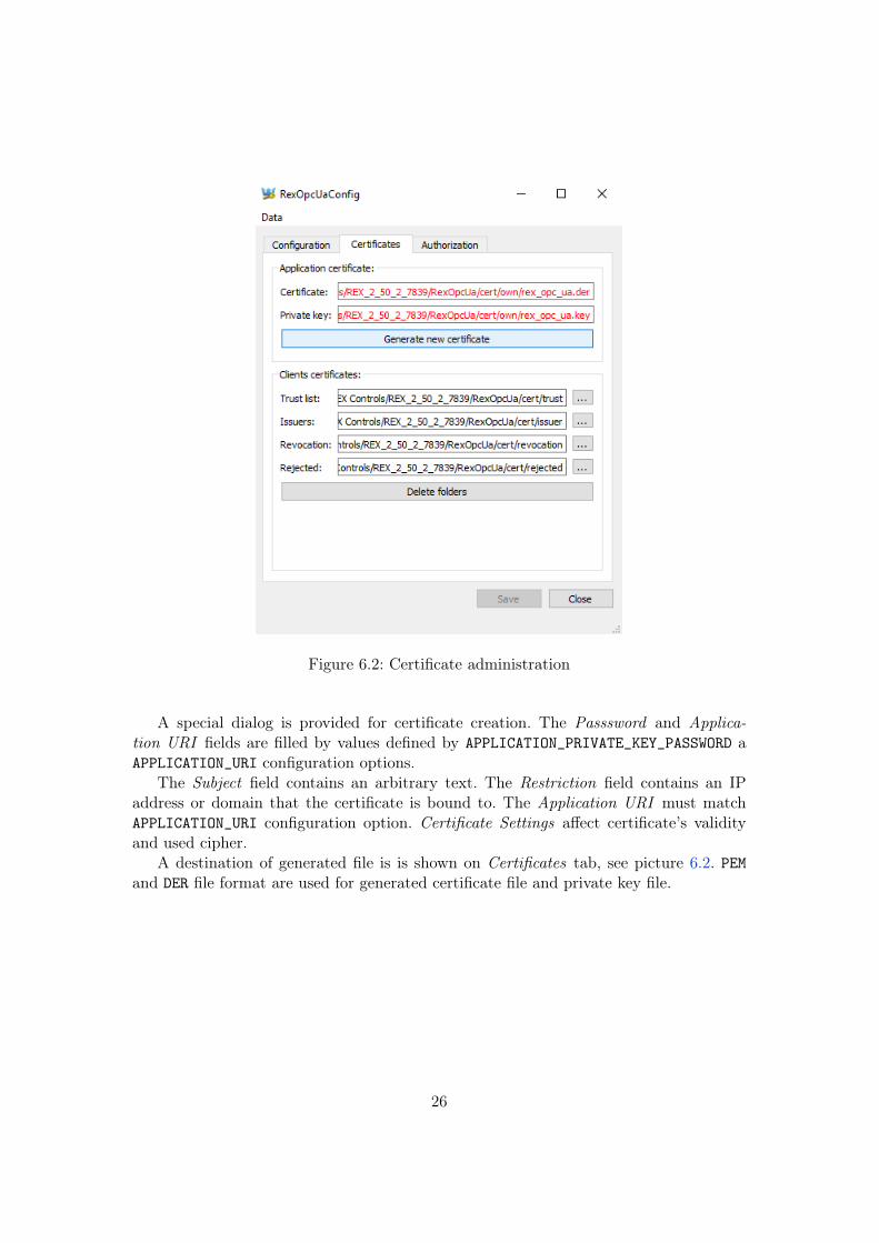
Figure 6.2: Certificate administration
A special dialog is provided for certificate creation. The Passsword and Applica-tion URI fields are filled by values defined by APPLICATION_PRIVATE_KEY_PASSWORD aAPPLICATION_URI configuration options.
The Subject field contains an arbitrary text. The Restriction field contains an IPaddress or domain that the certificate is bound to. The Application URI must matchAPPLICATION_URI configuration option. Certificate Settings affect certificate’s validityand used cipher.
A destination of generated file is is shown on Certificates tab, see picture 6.2. PEMand DER file format are used for generated certificate file and private key file.
26
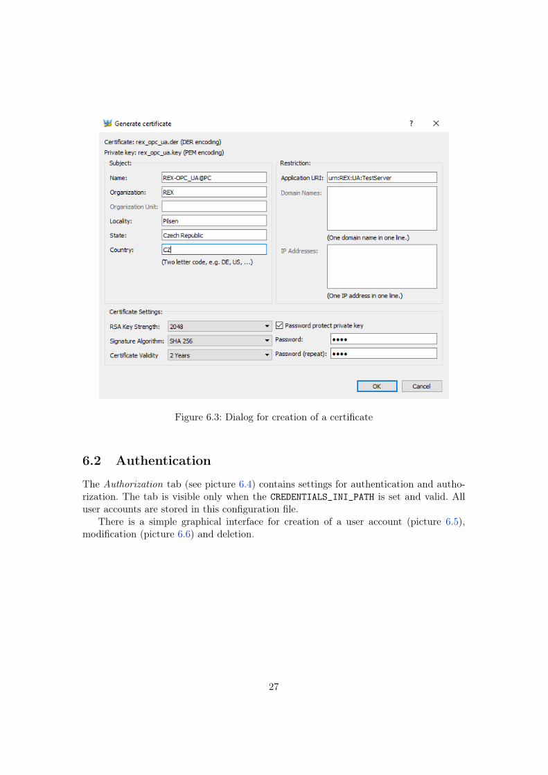
Figure 6.3: Dialog for creation of a certificate
6.2 Authentication
The Authorization tab (see picture 6.4) contains settings for authentication and autho-rization. The tab is visible only when the CREDENTIALS_INI_PATH is set and valid. Alluser accounts are stored in this configuration file.
There is a simple graphical interface for creation of a user account (picture 6.5),modification (picture 6.6) and deletion.
27
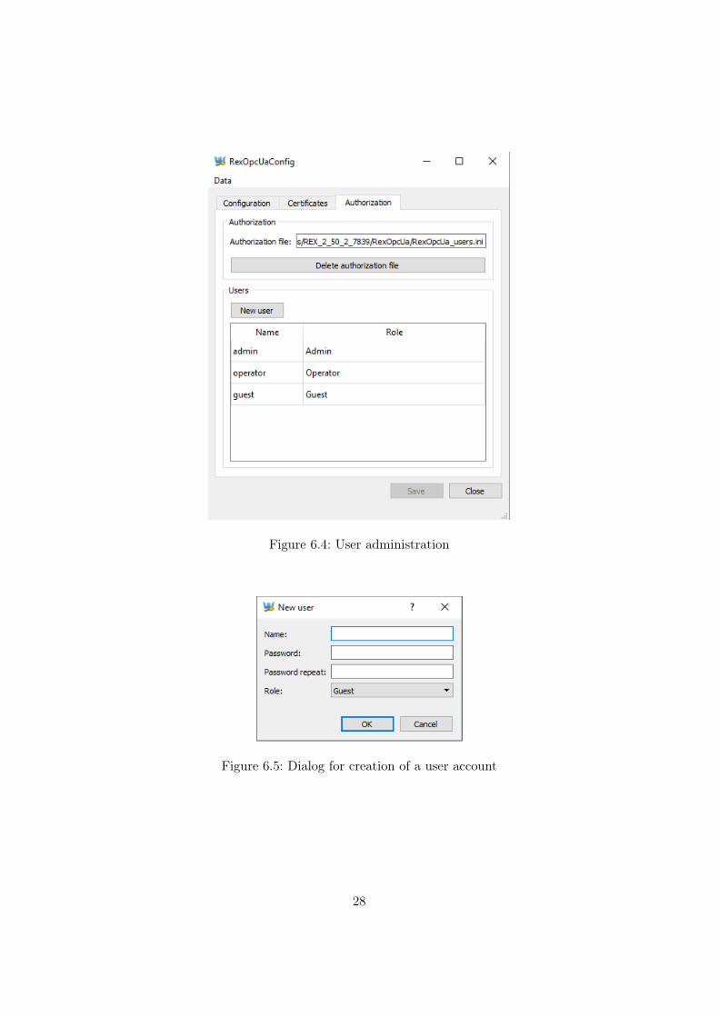
Figure 6.4: User administration
Figure 6.5: Dialog for creation of a user account
28
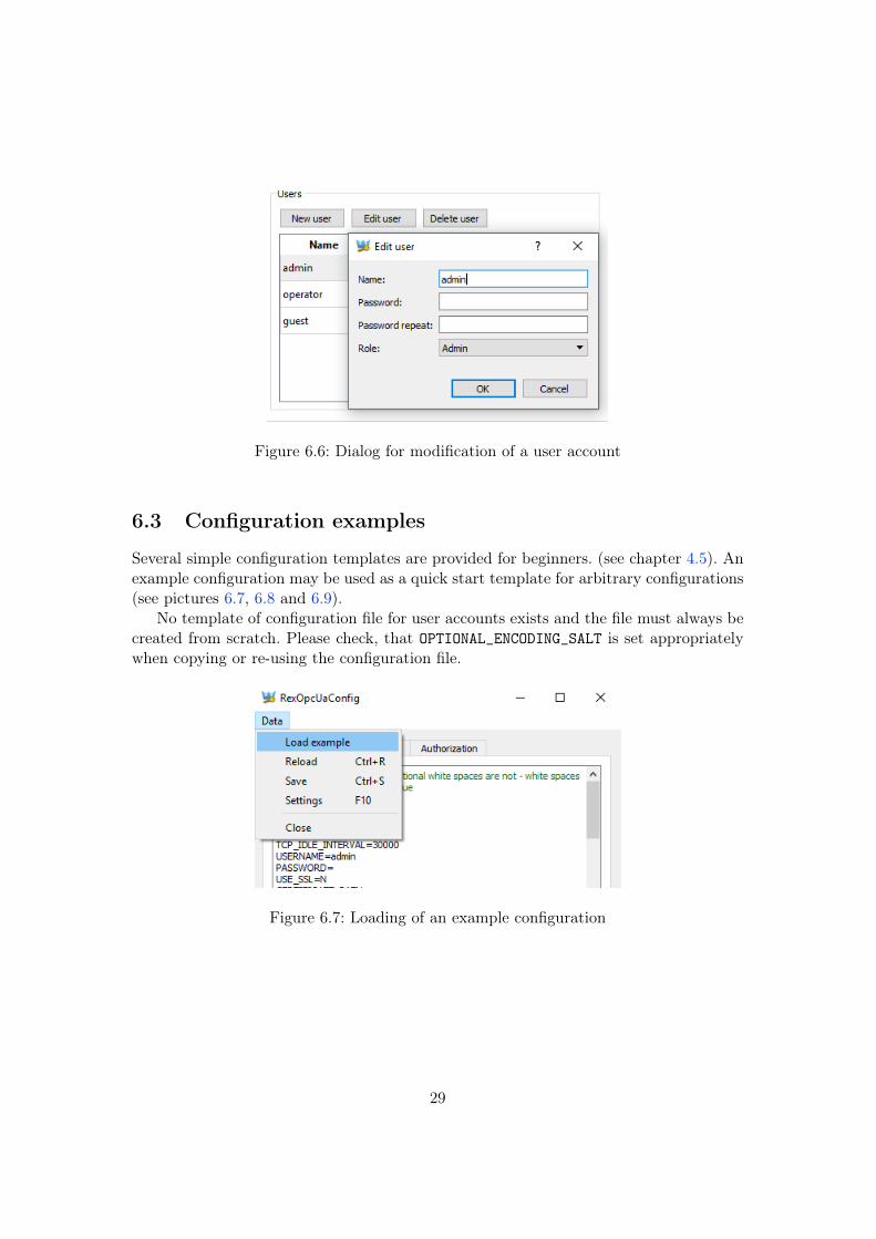
Figure 6.6: Dialog for modification of a user account
6.3 Configuration examples
Several simple configuration templates are provided for beginners. (see chapter 4.5). Anexample configuration may be used as a quick start template for arbitrary configurations(see pictures 6.7, 6.8 and 6.9).
No template of configuration file for user accounts exists and the file must always becreated from scratch. Please check, that OPTIONAL_ENCODING_SALT is set appropriatelywhen copying or re-using the configuration file.
Figure 6.7: Loading of an example configuration
29
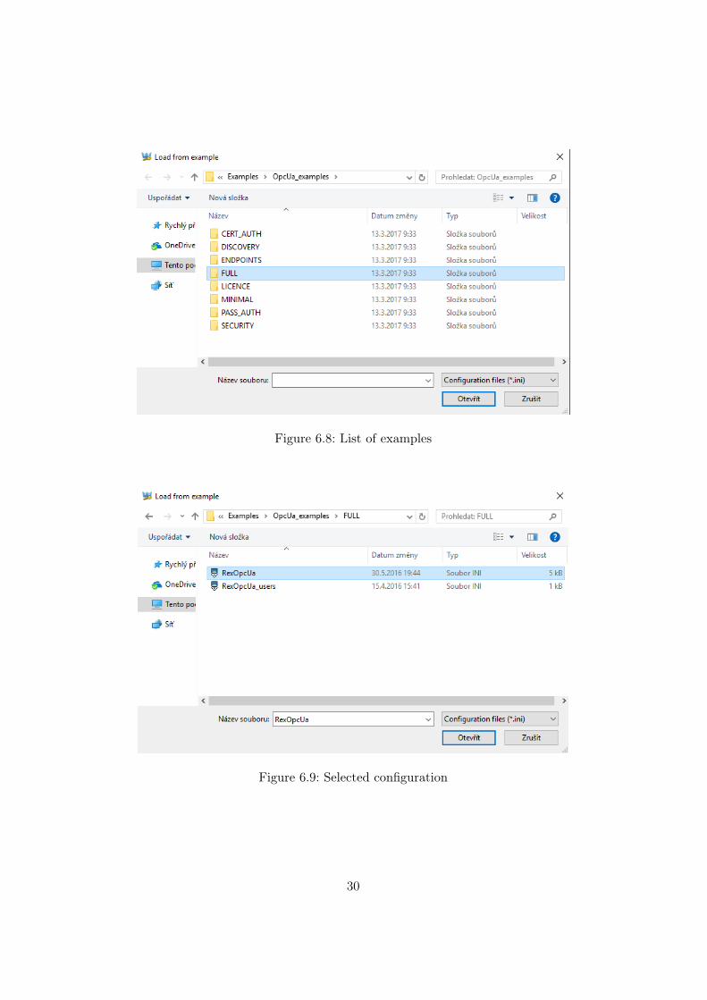
Figure 6.8: List of examples
Figure 6.9: Selected configuration
30
Chapter 7
Connection testing with OPC UAclients
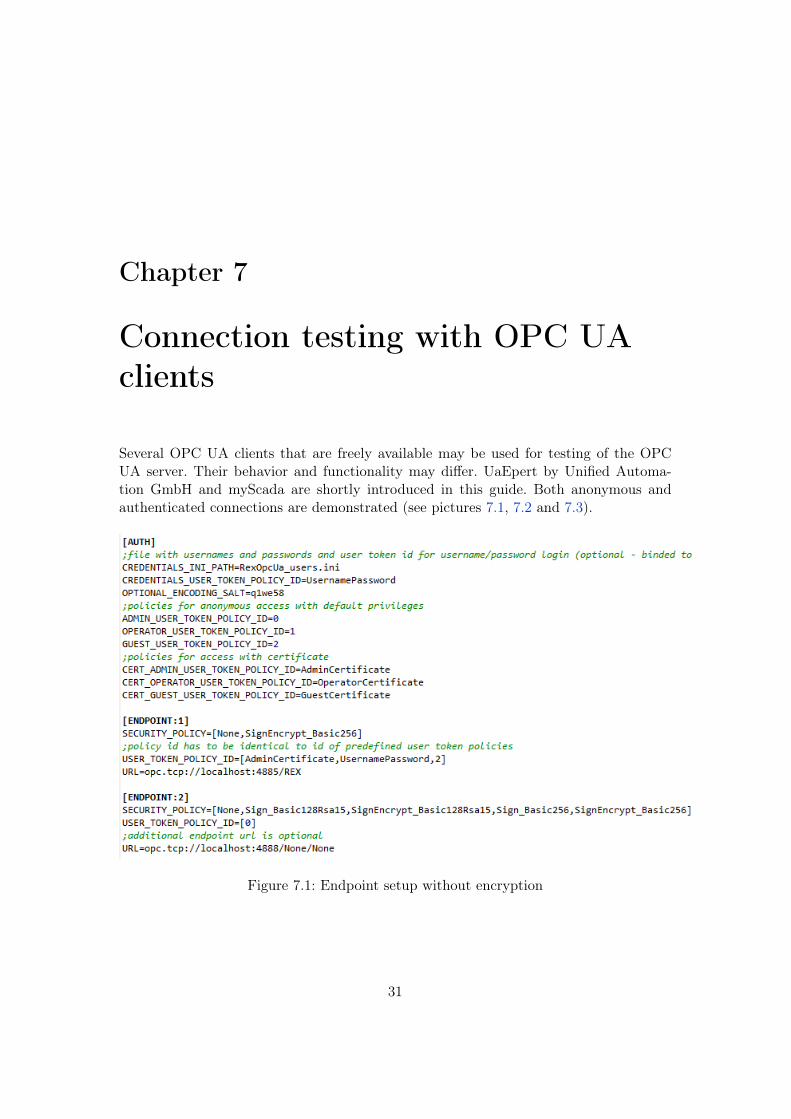
Several OPC UA clients that are freely available may be used for testing of the OPCUA server. Their behavior and functionality may differ. UaEpert by Unified Automa-tion GmbH and myScada are shortly introduced in this guide. Both anonymous andauthenticated connections are demonstrated (see pictures 7.1, 7.2 and 7.3).
Figure 7.1: Endpoint setup without encryption
31
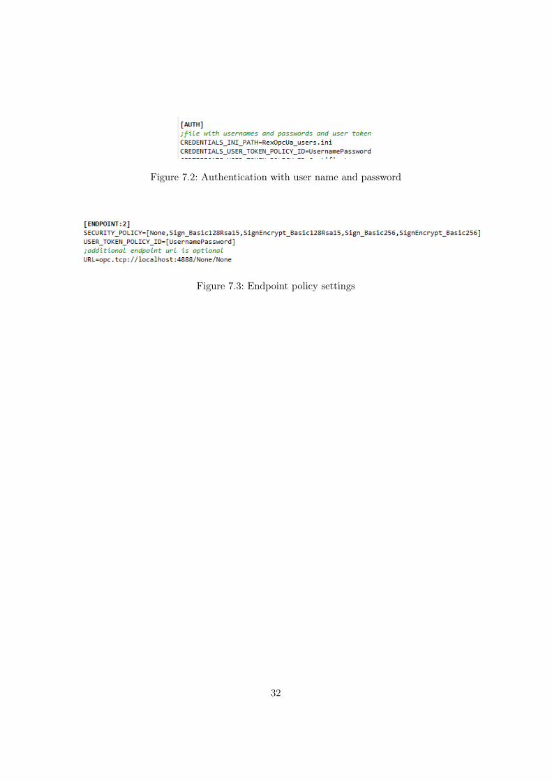
Figure 7.2: Authentication with user name and password
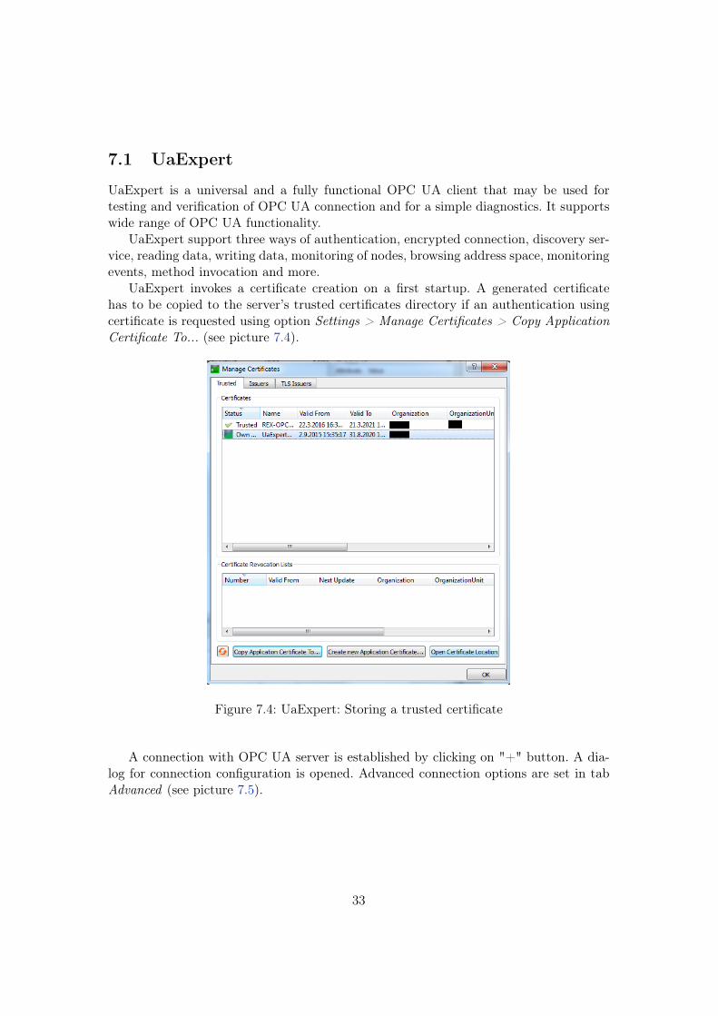
Figure 7.3: Endpoint policy settings
32
7.1 UaExpert
UaExpert is a universal and a fully functional OPC UA client that may be used fortesting and verification of OPC UA connection and for a simple diagnostics. It supportswide range of OPC UA functionality.
UaExpert support three ways of authentication, encrypted connection, discovery ser-vice, reading data, writing data, monitoring of nodes, browsing address space, monitoringevents, method invocation and more.
UaExpert invokes a certificate creation on a first startup. A generated certificatehas to be copied to the server’s trusted certificates directory if an authentication usingcertificate is requested using option Settings > Manage Certificates > Copy ApplicationCertificate To... (see picture 7.4).
Figure 7.4: UaExpert: Storing a trusted certificate
A connection with OPC UA server is established by clicking on "+" button. A dia-log for connection configuration is opened. Advanced connection options are set in tabAdvanced (see picture 7.5).
33
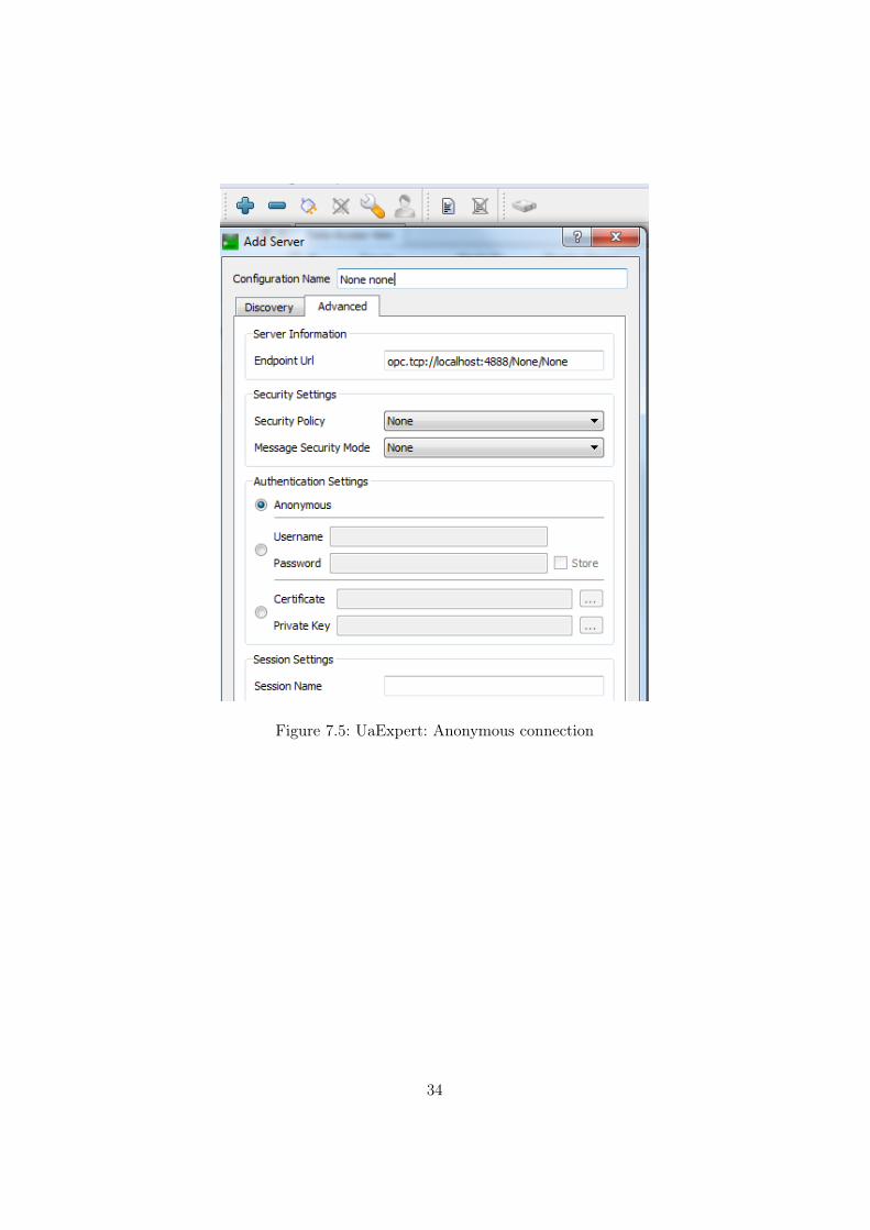
Figure 7.5: UaExpert: Anonymous connection
34
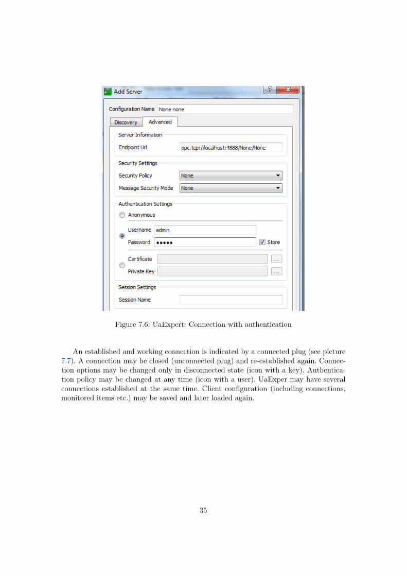
Figure 7.6: UaExpert: Connection with authentication
An established and working connection is indicated by a connected plug (see picture7.7). A connection may be closed (unconnected plug) and re-established again. Connec-tion options may be changed only in disconnected state (icon with a key). Authentica-tion policy may be changed at any time (icon with a user). UaExper may have severalconnections established at the same time. Client configuration (including connections,monitored items etc.) may be saved and later loaded again.
35
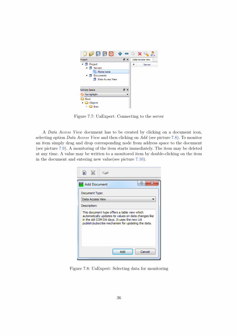
Figure 7.7: UaExpert: Connecting to the server
A Data Access View document has to be created by clicking on a document icon,selecting option Data Access View and then clicking on Add (see picture 7.8). To monitoran item simply drag and drop corresponding node from address space to the document(see picture 7.9). A monitoring of the item starts immediately. The item may be deletedat any time. A value may be written to a monitored item by double-clicking on the itemin the document and entering new value(see picture 7.10).
Figure 7.8: UaExpert: Selecting data for monitoring
36
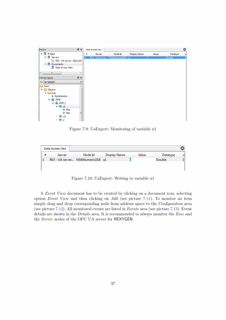
Figure 7.9: UaExpert: Monitoring of variable u1
Figure 7.10: UaExpert: Writing to variable u1
A Event View document has to be created by clicking on a document icon, selectingoption Event View and then clicking on Add (see picture 7.11). To monitor an itemsimply drag and drop corresponding node from address space to the Configuration area(see picture 7.12). All monitored events are listed in Events area (see picture 7.13). Eventdetails are shown in the Details area. It is recommended to always monitor the Exec andthe Server nodes of the OPC UA server for REXYGEN.
37
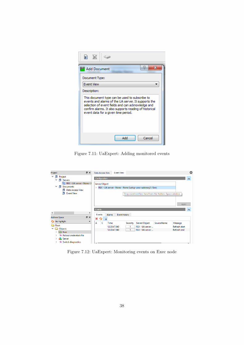
Figure 7.11: UaExpert: Adding monitored events
Figure 7.12: UaExpert: Monitoring events on Exec node
38
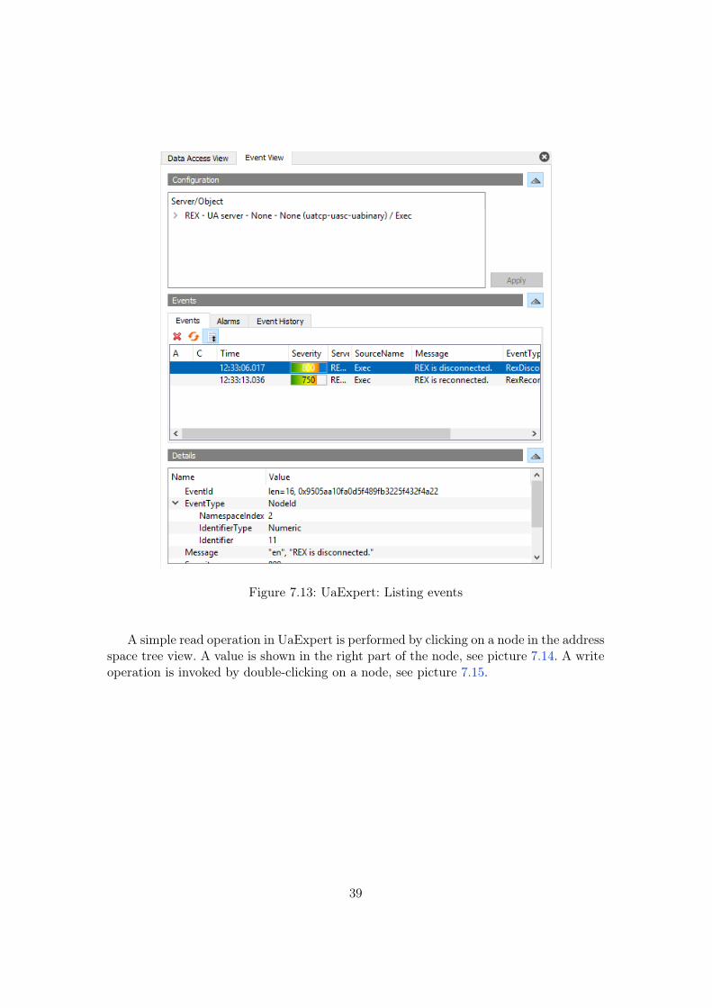
Figure 7.13: UaExpert: Listing events
A simple read operation in UaExpert is performed by clicking on a node in the addressspace tree view. A value is shown in the right part of the node, see picture 7.14. A writeoperation is invoked by double-clicking on a node, see picture 7.15.
39
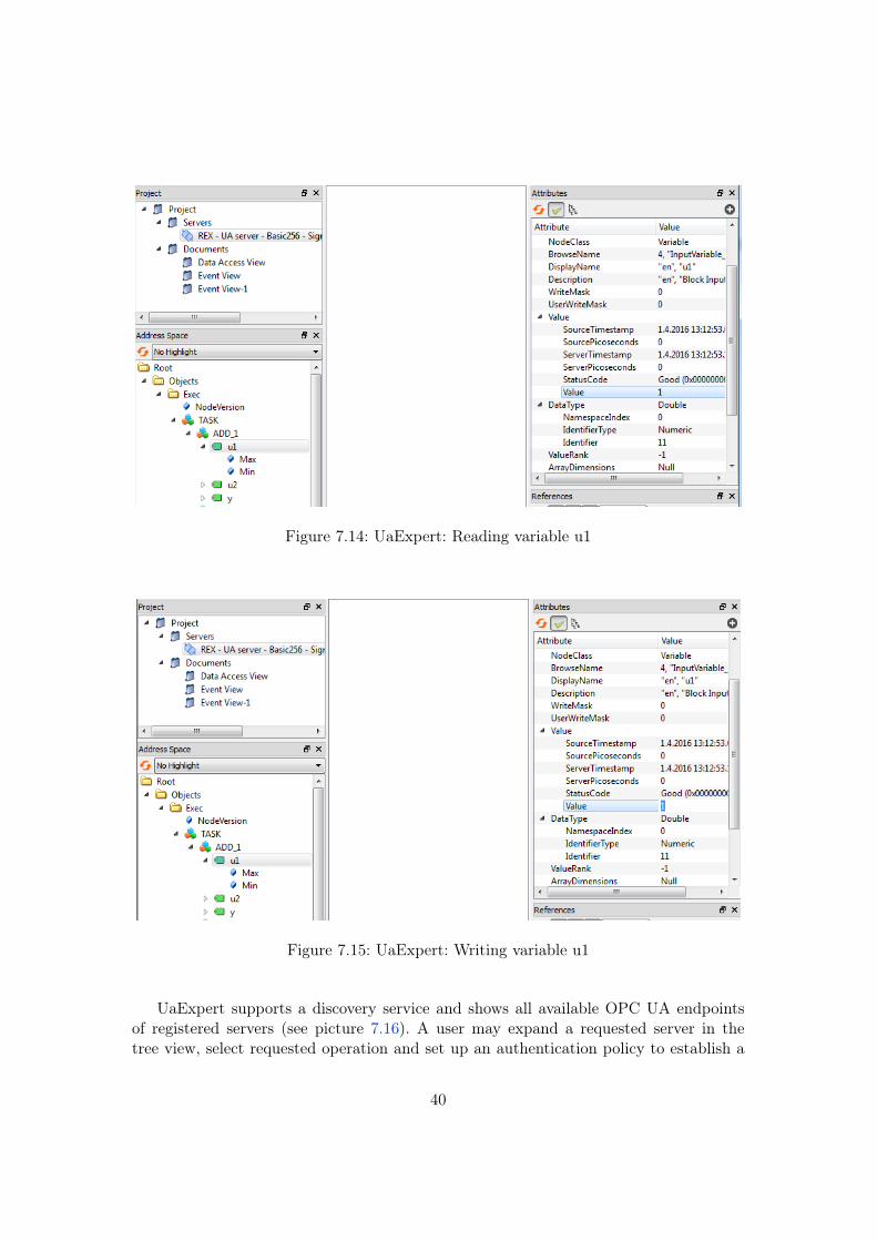
Figure 7.14: UaExpert: Reading variable u1
Figure 7.15: UaExpert: Writing variable u1
UaExpert supports a discovery service and shows all available OPC UA endpointsof registered servers (see picture 7.16). A user may expand a requested server in thetree view, select requested operation and set up an authentication policy to establish a
40
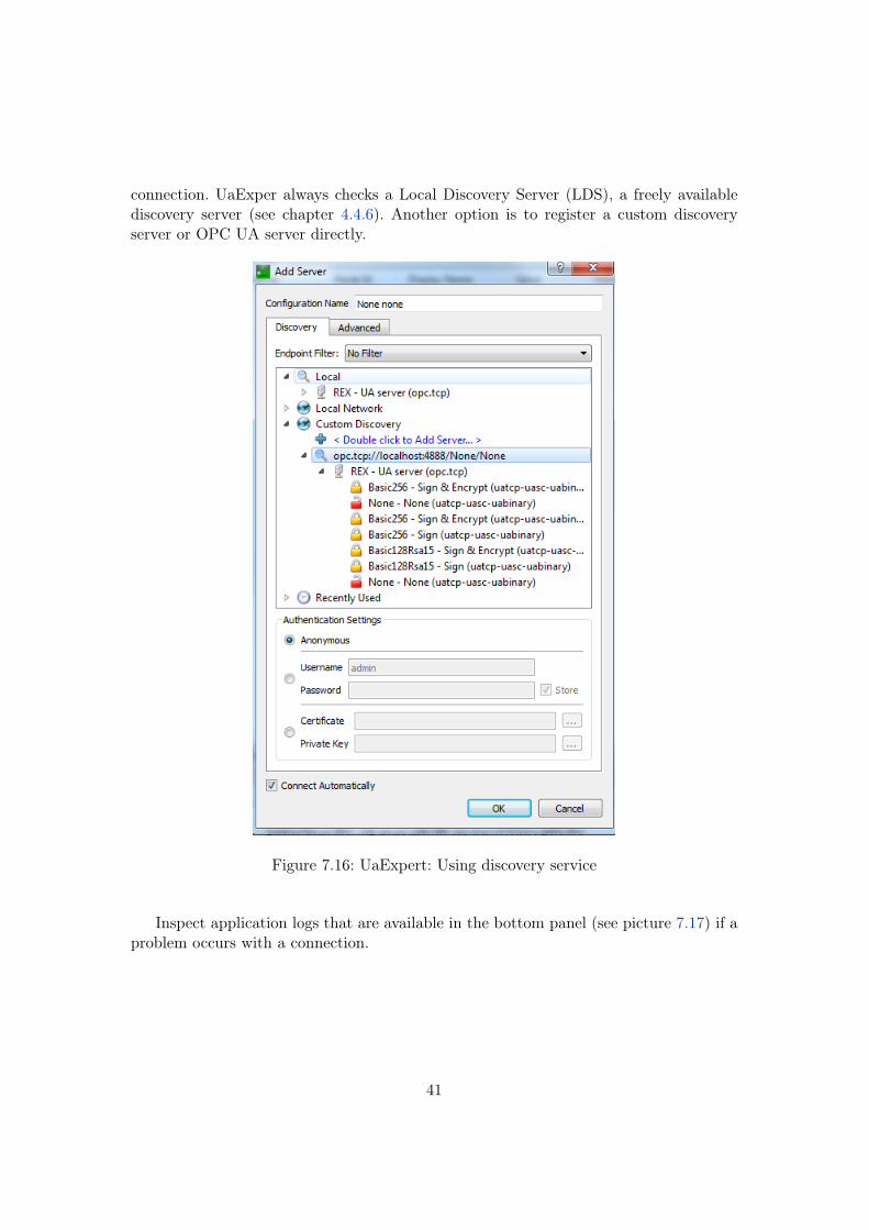
connection. UaExper always checks a Local Discovery Server (LDS), a freely availablediscovery server (see chapter 4.4.6). Another option is to register a custom discoveryserver or OPC UA server directly.
Figure 7.16: UaExpert: Using discovery service
Inspect application logs that are available in the bottom panel (see picture 7.17) if aproblem occurs with a connection.
41
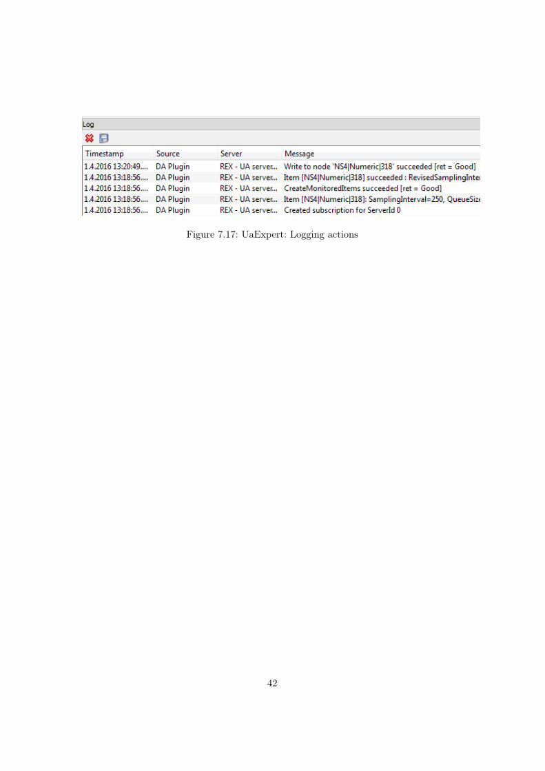
Figure 7.17: UaExpert: Logging actions
42
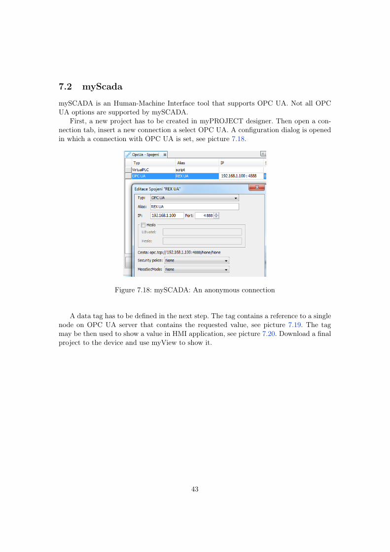
7.2 myScada
mySCADA is an Human-Machine Interface tool that supports OPC UA. Not all OPCUA options are supported by mySCADA.
First, a new project has to be created in myPROJECT designer. Then open a con-nection tab, insert a new connection a select OPC UA. A configuration dialog is openedin which a connection with OPC UA is set, see picture 7.18.
Figure 7.18: mySCADA: An anonymous connection
A data tag has to be defined in the next step. The tag contains a reference to a singlenode on OPC UA server that contains the requested value, see picture 7.19. The tagmay be then used to show a value in HMI application, see picture 7.20. Download a finalproject to the device and use myView to show it.
43
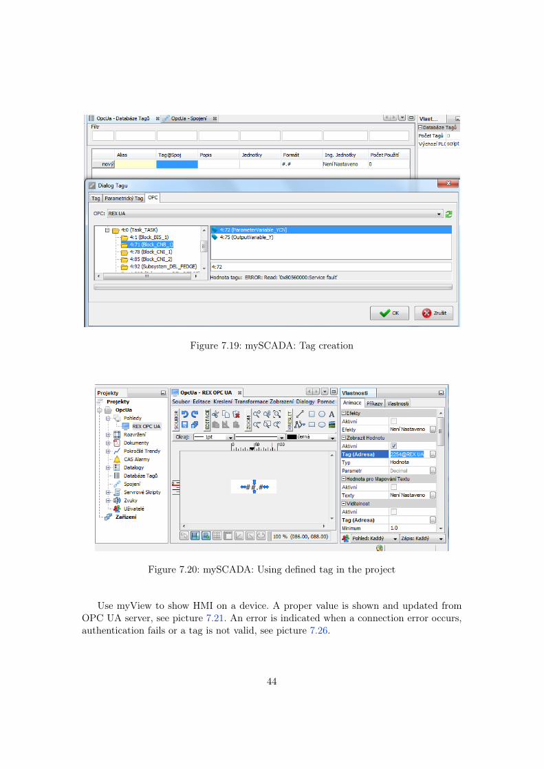
Figure 7.19: mySCADA: Tag creation
Figure 7.20: mySCADA: Using defined tag in the project
Use myView to show HMI on a device. A proper value is shown and updated fromOPC UA server, see picture 7.21. An error is indicated when a connection error occurs,authentication fails or a tag is not valid, see picture 7.26.
44
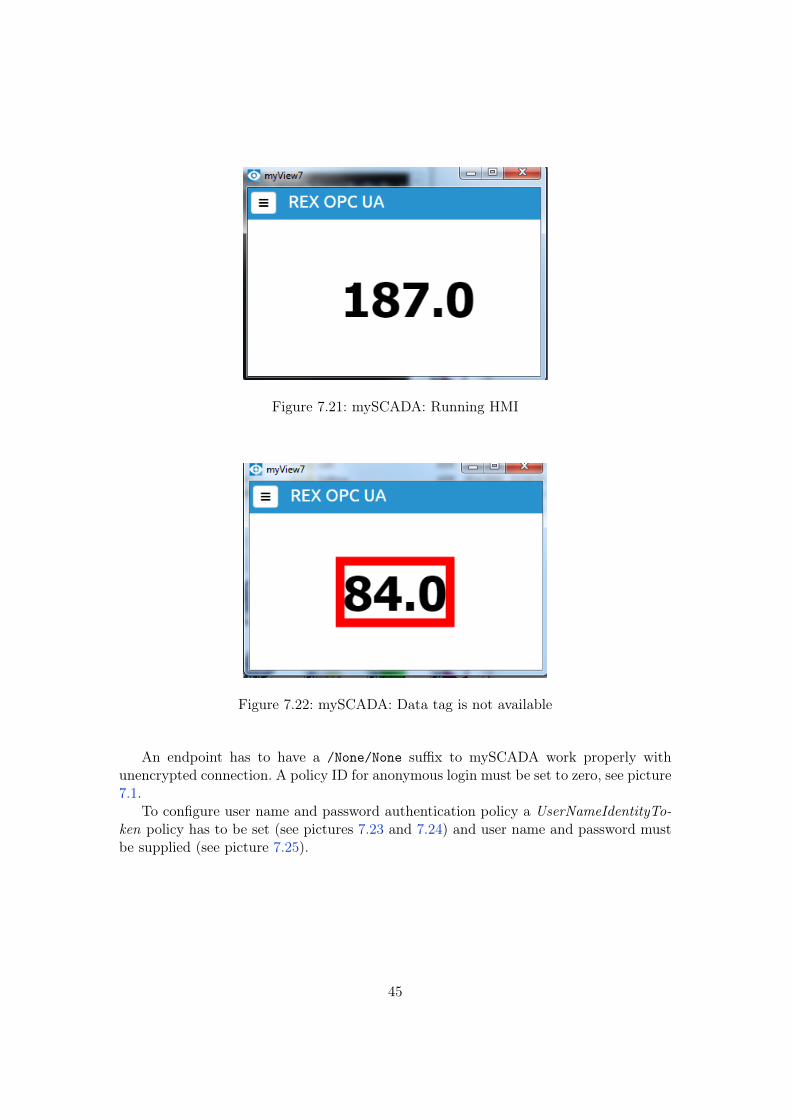
Figure 7.21: mySCADA: Running HMI
Figure 7.22: mySCADA: Data tag is not available
An endpoint has to have a /None/None suffix to mySCADA work properly withunencrypted connection. A policy ID for anonymous login must be set to zero, see picture7.1.
To configure user name and password authentication policy a UserNameIdentityTo-ken policy has to be set (see pictures 7.23 and 7.24) and user name and password mustbe supplied (see picture 7.25).
45
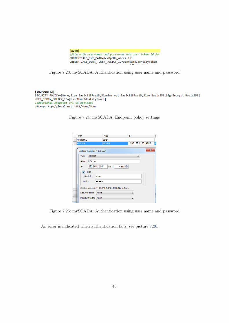
Figure 7.23: mySCADA: Authentication using user name and password
Figure 7.24: mySCADA: Endpoint policy settings
Figure 7.25: mySCADA: Authentication using user name and password
An error is indicated when authentication fails, see picture 7.26.
46
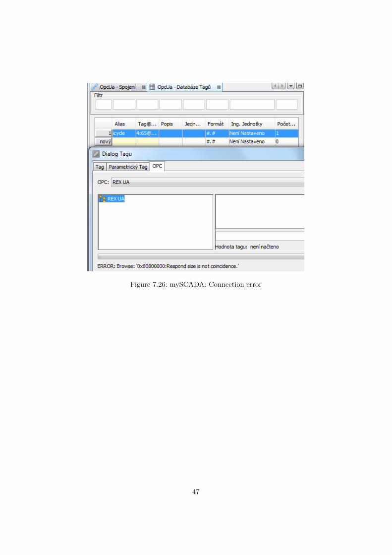
Figure 7.26: mySCADA: Connection error
47

Bibliography
Documentation reference number: 9228
48


![Using IEC 61499 and OPC-UA to implement a self-organising ...ceur-ws.org/Vol-2245/morse_paper_5.pdf · OPC-UA [14] (standardised as IEC 62541) is a vendor-neutral communication protocol](https://img.pdfslide.net/doc/110x75/5cfdd93e88c99367218bb342/using-iec-61499-and-opc-ua-to-implement-a-self-organising-ceur-wsorgvol-2245morsepaper5pdf.jpg)

![OPC UA Server - Maple Systems, Inc....OPC UA [Open Platform Communications Unified Architecture] is a machine to machine communication protocol designed for use in the Industrial Automation](https://img.pdfslide.net/doc/110x75/5e9d4aabcb6e9010aa717bc5/opc-ua-server-maple-systems-inc-opc-ua-open-platform-communications-unified.jpg)