Embed Size (px)
Citation preview
OPC Unified Architecture for
IO-Link Companion Specification
Specification
Draft Version 0.3.5 July 2018
Order No: 10.212
Editor note: Some changes may occur due to changes in the OPC UA for Devices specification. The section on profiles still need to be filled. Special handling for IODDs version 1.0 needs to be defined.
OPC Unified Architecture for IO-Link Companion Specification Draft 0.3.5
________________________________________________________________________________________________________ © Copyright IO-Link Community 2018 - All Rights Reserved Page 2 of 116
Draft for Executive Review. Do not Claim Conformance!
File name: OPC-UA_for_IO-Link_10212_d035_Jul18 This draft is published for testing and review only. It must not be used for development purposes. Prepared, approved and released by the IO-Link Community and the OPC Foundation.
Any comments, proposals, requests on this document are appreciated through the IO-Link CR database www.io-link-projects.com until 17.10.2018. Please provide name and email address. Login: IOL-OPC-Companion Password: Report
Important notes:
NOTE 1 The IO-Link Community Rules shall be observed prior to the development and marketing of IO-Link products. The document can be downloaded from the www.io-link.com portal.
NOTE 2 Any IO-Link device shall provide an associated IODD file. Easy access to the file and potential updates shall be possible. It is the responsibility of the IO-Link device manufacturer to test the IODD file with the help of the IODD-Checker tool available per download from www.io-link.com.
NOTE 3 Any IO-Link devices shall provide an associated manufacturer declaration on the conformity of the device. A corresponding form is available per download from www.io-link.com.
Disclaimer:
The attention of adopters is directed to the possibility that compliance with or adoption of IO-Link Community specifications may require use of an invention covered by patent rights. The IO-Link Community shall not be responsible for identifying patents for which a license may be required by any IO-Link Community specification, or for conducting legal inquiries into the legal validity or scope of those patents that are brought to its attention. IO-Link Community specifications are prospective and advisory only. Prospective users are responsible for protecting themselves against liability for infringement of patents.
The information contained in this document is subject to change without notice. The material in this document details an IO-Link Community specification in accordance with the license and notices set forth on this page. This document does not represent a commitment to implement any portion of this specification in any company's products.
WHILE THE INFORMATION IN THIS PUBLICATION IS BELIEVED TO BE ACCURATE, THE IO-LINK COMMUNITY MAKES NO WARRANTY OF ANY KIND, EXPRESS OR IMPLIED, WITH REGARD TO THIS MATERIAL INCLUDING, BUT NOT LIMITED TO ANY WARRANTY OF TITLE OR OWNERSHIP, IMPLIED WARRANTY OF MERCHANTABILITY OR WARRANTY OF FITNESS FOR PARTICULAR PURPOSE OR USE.
In no event shall the IO-Link Community be liable for errors contained herein or for indirect, incidental, special, consequential, reliance or cover damages, including loss of profits, revenue, data or use, incurred by any user or any third party. Compliance with this specification does not absolve manufacturers of IO-Link equipment, from the requirements of safety and regulatory agencies (TÜV, BIA, UL, CSA, etc.).
® is registered trade mark. The use is restricted to members of the IO-Link Community. More detailed terms for the use can be found in the IO-Link Community Rules on www.io-link.com.
Conventions: In this specification the following key words (in bold text) will be used: may: indicates flexibility of choice with no implied preference. should: indicates flexibility of choice with a strongly preferred implementation. shall: indicates a mandatory requirement. Designers shall implement such mandatory requirements to ensure
interoperability and to claim conformity with this specification. Publisher: IO-Link Community Haid-und-Neu-Str. 7 76131 Karlsruhe Germany Phone: +49 721 / 96 58 590 Fax: +49 721 / 96 58 589 E-mail: [email protected] Web site: www.io-link.com © No part of this publication may be reproduced or utilized in any form or by any means, electronic or mechanical, including photocopying and microfilm, without permission in writing from the publisher.
OPC Unified Architecture for IO-Link Companion Specification Draft 0.3.5
________________________________________________________________________________________________________ © Copyright IO-Link Community 2018 - All Rights Reserved Page 3 of 116
Draft for Executive Review. Do not Claim Conformance!
CONTENTS Page
1 Scope ............................................................................................................................. 12 2 Normative References .................................................................................................... 13 3 Terms, Definitions, and Conventions .............................................................................. 13
3.1 Overview ............................................................................................................... 13 3.2 OPC UA for IO-Link Information Model Terms ....................................................... 13
3.2.1 IO-Link Device ........................................................................................... 13 3.2.2 IO-Link Master ........................................................................................... 14
3.3 Abbreviations and Symbols ................................................................................... 14 3.4 Conventions used in this Document ....................................................................... 14
3.4.1 Conventions for Node Descriptions ............................................................ 14 3.4.2 NodeIds and BrowseNames ....................................................................... 16
3.4.2.1 NodeIds ...................................................................................... 16 3.4.2.2 BrowseNames ............................................................................. 16
3.4.3 Common Attributes .................................................................................... 16 3.4.3.1 General ....................................................................................... 16 3.4.3.2 Objects ....................................................................................... 17 3.4.3.3 Variables .................................................................................... 17 3.4.3.4 VariableTypes ............................................................................. 17 3.4.3.5 Methods ...................................................................................... 18
4 General Information on IO-Link and OPC UA .................................................................. 19 4.1 Introduction to IO-Link ........................................................................................... 19
4.1.1 What is IO-Link? ........................................................................................ 19 4.1.2 Basics of IO-Link ....................................................................................... 19 4.1.3 Device Description .................................................................................... 19
4.2 Introduction to OPC Unified Architecture ............................................................... 20 4.2.1 What is OPC UA? ...................................................................................... 20 4.2.2 Basics of OPC UA ..................................................................................... 20 4.2.3 Information Modelling in OPC UA .............................................................. 21
4.2.3.1 Concepts .................................................................................... 21 4.2.3.2 Graphical Notation ...................................................................... 22
4.2.4 OPC UA Profiles ........................................................................................ 23 4.2.5 Namespaces.............................................................................................. 23 4.2.6 Companion Specifications ......................................................................... 23
5 Combining OPC UA and IO-Link ..................................................................................... 24 5.1 System Architecture .............................................................................................. 24 5.2 Use Cases ............................................................................................................ 24
5.2.1 UC.001: Configure an IO-Link Master ........................................................ 24 5.2.2 UC.002: Find IO-Link Masters .................................................................... 24 5.2.3 UC.003: Find IO-Link Devices.................................................................... 25 5.2.4 UC.004: Initial commissioning of IO-Link Device ........................................ 25 5.2.5 UC.005: Configure device metadata .......................................................... 25 5.2.6 UC.006: Configure IO-Link subscriptions ................................................... 25 5.2.7 UC.007: Disconnection of IO-Link Device .................................................. 25 5.2.8 UC.008: Read-product identification .......................................................... 25 5.2.9 UC.009: Read diagnostics data ................................................................. 25 5.2.10 UC.010: Read operating and failure statistics ............................................ 26 5.2.11 UC.011: Reset operating and failure statistics ........................................... 26
OPC Unified Architecture for IO-Link Companion Specification Draft 0.3.5
________________________________________________________________________________________________________ © Copyright IO-Link Community 2018 - All Rights Reserved Page 4 of 116
Draft for Executive Review. Do not Claim Conformance!
5.2.12 UC.012: Optimize machine settings ........................................................... 26 5.2.13 UC.013: Plant and machine status supervision .......................................... 26 5.2.14 UC.014: Faulty device replacement ........................................................... 27 5.2.15 UC.015: Firmware update .......................................................................... 27 5.2.16 UC.016: Asset Management ...................................................................... 27 5.2.17 UC.017: Cloud-connectivity at Edge Gateway ............................................ 27
6 IO-Link Information Model Overview ............................................................................... 27 6.1 Modelling Concepts ............................................................................................... 27
6.1.1 IO-Link Master ........................................................................................... 27 6.1.2 IO-Link Port ............................................................................................... 27 6.1.3 IO-Link Device ........................................................................................... 27 6.1.4 IO-Link Events ........................................................................................... 28 6.1.5 Block operations: Up- and Download ......................................................... 28 6.1.6 Managing IODDs ....................................................................................... 28 6.1.7 Relating IO-Link Devices to IO-Link Ports .................................................. 28
6.2 Model Overview ..................................................................................................... 31 6.3 Mapping IODD information to OPC UA ObjectTypes .............................................. 34
7 OPC UA ObjectTypes ..................................................................................................... 36 7.1 IOLinkDeviceType ObjectType Definition ............................................................... 36
7.1.1 Example .................................................................................................... 36 7.1.2 Overview ................................................................................................... 38 7.1.3 Variables of ParameterSet ......................................................................... 42 7.1.4 Methods of MethodSet ............................................................................... 43
7.1.4.1 ReadISDU ................................................................................... 44 7.1.4.2 WriteISDU ................................................................................... 44 7.1.4.3 SystemCommand ........................................................................ 45 7.1.4.4 ParamUploadFromDeviceStart .................................................... 45 7.1.4.5 ParamUploadFromDeviceStop .................................................... 46 7.1.4.6 ParamDownloadToDeviceStart .................................................... 46 7.1.4.7 ParamDownloadToDeviceStop .................................................... 46 7.1.4.8 ParamDownloadToDeviceStore ................................................... 46 7.1.4.9 ParamBreak ................................................................................ 47 7.1.4.10 DeviceReset ............................................................................... 47 7.1.4.11 ApplicationReset ......................................................................... 47 7.1.4.12 RestoreFactorySettings ............................................................... 47
7.2 IOLinkIODDDeviceType ......................................................................................... 47 7.2.1 General information on IODDs ................................................................... 47 7.2.2 Example .................................................................................................... 48 7.2.3 Overview ................................................................................................... 49 7.2.4 Variables of the ParameterSet Object ........................................................ 50 7.2.5 Variables of the IODDInformation Object ................................................... 50 7.2.6 Variables of the DeviceTypeImage Object ................................................. 50
7.3 ObjectTypes generated based on IODDs ............................................................... 50 7.3.1 General ..................................................................................................... 50 7.3.2 NodeId of generated ObjectTypes and their InstanceDeclarations ............. 51 7.3.3 Namespace of the BrowseNames .............................................................. 51 7.3.4 Mapping to InstanceDeclarations inherited from IOLinkDeviceType ........... 51 7.3.5 Mapping of IODD Menus ............................................................................ 51 7.3.6 Mapping of IODD Variables ....................................................................... 53
OPC Unified Architecture for IO-Link Companion Specification Draft 0.3.5
________________________________________________________________________________________________________ © Copyright IO-Link Community 2018 - All Rights Reserved Page 5 of 116
Draft for Executive Review. Do not Claim Conformance!
7.3.7 Mapping of Methods from IODD Menus ..................................................... 56 7.3.8 Mapping of StdVariableRef and StdRecordItemRef .................................... 57 7.3.9 Mapping of ProcessDataCollection and ProcessDataRefCollection ............ 58 7.3.10 Mapping of DirectParameterOverlay .......................................................... 59 7.3.11 Mapping of Default Values ......................................................................... 59 7.3.12 Mapping of DeviceVariantCollection .......................................................... 60 7.3.13 Mapping of EventCollection ....................................................................... 61
7.4 Creation of Instances based on ObjectTypes generated out of IODDs ................... 61 7.5 IOLinkMasterType ObjectType Definition ............................................................... 64
7.5.1 Example .................................................................................................... 64 7.5.2 Overview ................................................................................................... 66 7.5.3 Variables of ParameterSet ......................................................................... 70 7.5.4 Methods of MethodSet ............................................................................... 71
7.5.4.1 Restart ........................................................................................ 71 7.5.4.2 ResetStatisticsOnAllPorts ........................................................... 72
7.6 IOLinkPortType ObjectType Definition ................................................................... 72 7.6.1 Example .................................................................................................... 72 7.6.2 Overview ................................................................................................... 74 7.6.3 Variables of ParameterSet ......................................................................... 76 7.6.4 Methods of MethodSet ............................................................................... 80
7.6.4.1 ResetStatistics ............................................................................ 80 7.6.4.2 UpdateConfiguration ................................................................... 81
7.7 DeviceVariantType ................................................................................................ 81 7.8 NetworkConfigurationType .................................................................................... 82 7.9 IPv4ConfigurationType .......................................................................................... 82 7.10 IPv6ConfigurationType .......................................................................................... 83 7.11 DNSConfigurationType .......................................................................................... 84 7.12 EthernetPortInformationType ................................................................................. 84
8 OPC UA Objects, Variables and Methods ....................................................................... 85 8.1 General ................................................................................................................. 85 8.2 IODDManagement Object ...................................................................................... 85 8.3 RemoveIODD Method ............................................................................................ 87
9 OPC UA EventTypes ...................................................................................................... 87 9.1 General ................................................................................................................. 87 9.2 IOLinkEventType ................................................................................................... 88 9.3 IOLinkDeviceEventType ........................................................................................ 88 9.4 IOLinkIODDDeviceEventType ................................................................................ 89 9.5 IOLinkPortEventType ............................................................................................ 89 9.6 IOLinkMasterEventType ........................................................................................ 90 9.7 IOLinkAlarmType ................................................................................................... 91 9.8 IOLinkDeviceAlarmType ........................................................................................ 92 9.9 IOLinkIODDDeviceAlarmType................................................................................ 93 9.10 IOLinkPortAlarmType ............................................................................................ 93 9.11 IOLinkMasterAlarmType ........................................................................................ 94
10 OPC UA VariableTypes .................................................................................................. 95 10.1 ProcessDataVariableType ..................................................................................... 95
11 OPC UA ReferenceTypes ............................................................................................... 95 11.1 HasIdentificationMenu ........................................................................................... 95 11.2 HasParameterMenu ............................................................................................... 96
OPC Unified Architecture for IO-Link Companion Specification Draft 0.3.5
________________________________________________________________________________________________________ © Copyright IO-Link Community 2018 - All Rights Reserved Page 6 of 116
Draft for Executive Review. Do not Claim Conformance!
11.3 HasObservationMenu ............................................................................................ 96 11.4 HasDiagnosisMenu ............................................................................................... 97
12 Mapping of DataTypes .................................................................................................... 98 12.1 Overview ............................................................................................................... 98 12.2 Primitive DataTypes .............................................................................................. 98
12.2.1 Boolean DataType ..................................................................................... 98 12.2.2 Integer DataTypes ..................................................................................... 98 12.2.3 Float DataType .......................................................................................... 99 12.2.4 String DataType ...................................................................................... 100 12.2.5 Byte[] DataType ....................................................................................... 100 12.2.6 DateTime DataType ................................................................................. 100
12.2.6.1 Overview ................................................................................... 100 12.2.6.2 Conversion from IO-Link TimeT to OPC UA DateTime ............... 100 12.2.6.3 Conversion from OPC UA DateTime to IO-Link TimeT ............... 101 12.2.6.4 Conversion of special values (Summary) ................................... 102
12.2.7 Duration DataType .................................................................................. 102 12.2.7.1 Duration DataType used for TimeSpanT .................................... 102 12.2.7.2 Duration DataType used for values coded with 1 byte ............... 103
12.3 Mapping of Records and Arrays........................................................................... 103 12.3.1 Overview ................................................................................................. 103 12.3.2 Structure DataType ................................................................................. 103 12.3.3 Array DataTypes ...................................................................................... 105
12.4 Enumeration DataTypes ...................................................................................... 105 12.4.1 EncodingEnum ........................................................................................ 105
13 Standardized Properties and Mapping to the Properties ............................................... 106 13.1 InstrumentRange ................................................................................................. 106 13.2 InstrumentRanges ............................................................................................... 106 13.3 EnumValues ........................................................................................................ 106 13.4 TrueState and FalseState .................................................................................... 106 13.5 Encoding ............................................................................................................. 106 13.6 DisplayFormat ..................................................................................................... 107
14 ISDU Error Handling ..................................................................................................... 108 14.1 Overview ............................................................................................................. 108 14.2 Occurrence of ISDU Errors .................................................................................. 108 14.3 Mapping of ISDU Errors in DiagnosticInfo ............................................................ 108 14.4 Content of localizedText in DiagnosticInfo ........................................................... 109
14.4.1 No IODD information available ................................................................ 109 14.4.2 IODD information available ...................................................................... 109
15 Profiles and Namespaces ............................................................................................. 110 15.1 Namespace Metadata .......................................................................................... 110 15.2 Conformance Units and Profiles .......................................................................... 110 15.3 Server Facets ...................................................................................................... 110 15.4 Client Facets ....................................................................................................... 111 15.5 Handling of OPC UA namespaces ....................................................................... 111
Annex A (normative): OPC UA for IO-Link Namespace and Mappings ................................. 113 A.1 Namespace and identifiers for OPC UA for IO-Link Information Model ................. 113 A.2 Profile URIs for OPC UA for IO-Link Information Model ....................................... 113
Annex B (informative): Aggregation as System Architecture Option..................................... 114 B.1 Overview ............................................................................................................. 114
OPC Unified Architecture for IO-Link Companion Specification Draft 0.3.5
________________________________________________________________________________________________________ © Copyright IO-Link Community 2018 - All Rights Reserved Page 7 of 116
Draft for Executive Review. Do not Claim Conformance!
B.2 System Architecture ............................................................................................ 114 Annex C (normative): EngineeringUnits .............................................................................. 115
C.1 Overview ............................................................................................................. 115
OPC Unified Architecture for IO-Link Companion Specification Draft 0.3.5
________________________________________________________________________________________________________ © Copyright IO-Link Community 2018 - All Rights Reserved Page 8 of 116
Draft for Executive Review. Do not Claim Conformance!
FIGURES
Figure 1 – System Architecture with IO-Link (Example) ......................................................... 19 Figure 2 – The Scope of OPC UA within an Enterprise .......................................................... 20 Figure 3 – The Relationship between Type Definitions and Instances ................................... 22 Figure 4 – The OPC UA Information Model Notation ............................................................. 23 Figure 5 – System Architecture of IO-Link and OPC UA (Example) ....................................... 24 Figure 6 – State machine describing if an Object is connected to an IO-Link Port ................. 30 Figure 7 – IO-Link Information Model overview (Structure) .................................................... 32 Figure 8 – IO-Link Information Model overview (Events) ....................................................... 33 Figure 9 – AddressSpace entry points ................................................................................... 34 Figure 10 – Example of Simplified Mapping of IODD Menus to OPC UA Functional Groups .. 35 Figure 11 – Example instance of IOLinkDeviceType (no optional InstanceDeclarations shown and some mandatory Methods left out) ...................................................................... 37 Figure 12 – Example instance of IOLinkIODDDeviceType (no optional InstanceDeclarations shown) ................................................................................................ 48 Figure 13 – Example on how to map IODD Menus from UserInterface .................................. 52 Figure 14 – Example on how to map IODD Menus containing IODD Menus .......................... 53 Figure 15 – Example on how to map Variables...................................................................... 54 Figure 16 – Example on how to map Variables with different VariableRefs ............................ 55 Figure 17 – Example on how to map Variables with RecordItemRefs .................................... 55 Figure 18 – Example on how to map IODD Buttons to OPC UA Methods .............................. 56 Figure 19 – Example on how to map IODD ProcessDataCollection ....................................... 59 Figure 20 – Example on how to map Default Values ............................................................. 60 Figure 21 – Example on how to map DeviceVariantCollection ............................................... 60 Figure 22 – Example of an Object based on an IODD ........................................................... 63 Figure 23 – Example of an Object based on an IODD using different VariableRefs ............... 64 Figure 24 – Example instance of IOLinkMasterType (only mandatory InstanceDeclarations) ........................................................................................................... 65 Figure 25 – Example instance of IOLinkPortType (only mandatory InstanceDeclarations) ..... 73 Figure 26 – Example AddressSpace containing the IODDManagement Object ...................... 85 Figure 27 –System Architecture using an OPC UA aggregation server for IODD capabilities (Example) ......................................................................................................... 114
OPC Unified Architecture for IO-Link Companion Specification Draft 0.3.5
________________________________________________________________________________________________________ © Copyright IO-Link Community 2018 - All Rights Reserved Page 9 of 116
Draft for Executive Review. Do not Claim Conformance!
TABLES Table 1 – Examples of DataTypes ......................................................................................... 15 Table 2 – Type Definition Table ............................................................................................ 15 Table 3 – Common Node Attributes ...................................................................................... 17 Table 4 – Common Object Attributes ..................................................................................... 17 Table 5 – Common Variable Attributes .................................................................................. 17 Table 6 – Common VariableType Attributes .......................................................................... 18 Table 7 – Common Method Attributes ................................................................................... 18 Table 8 – IOLinkDeviceType Definition ................................................................................. 38 Table 9 – References of Identification Object ........................................................................ 39 Table 10 – Mapping of IO-Link Device Status to OPC UA DeviceHealth ................................ 40 Table 11 – References of General Object ............................................................................. 40 Table 12 – ParameterSet of IOLinkDeviceType ..................................................................... 42 Table 13 – Properties of ApplicationSpecificTag ................................................................... 42 Table 14 – Properties of FunctionTag ................................................................................... 42 Table 15 – Properties of LocationTag ................................................................................... 43 Table 16 – MethodSet of IOLinkDeviceType ......................................................................... 44 Table 17 – IOLinkIODDDeviceType Definition ....................................................................... 49 Table 18 – ParameterSet of IOLinkIODDDeviceType ............................................................ 50 Table 19 – IODDInformation of IOLinkIODDDeviceType ........................................................ 50 Table 20 – ParameterSet of IOLinkIODDDeviceType ............................................................ 50 Table 21 – Mapping of StdVariableRefs to IOLinkDeviceType Instance Declarations ............ 57 Table 22 – Mapping of StdRecordItemRefs to IOLinkDeviceType Instance Declarations ....... 57 Table 23 – IOLinkMasterType Definition ............................................................................... 66 Table 24 – References of Identification Object ...................................................................... 67 Table 25 – References of Capabilities Object........................................................................ 68 Table 26 – References of Management Object ...................................................................... 68 Table 27 – References of Statistics Object............................................................................ 68 Table 28 – ParameterSet of IOLinkMasterType ..................................................................... 70 Table 29 – Defined elements of EnumStrings array of MasterType Variable .......................... 71 Table 30 – MethodSet of IOLinkMasterType ......................................................................... 71 Table 31 – IOLinkPortType Definition .................................................................................... 74 Table 32 – References of Capabilities Object........................................................................ 75 Table 33 – References of Configuration Object ..................................................................... 75 Table 34 – References of ConfiguredDevice Object .............................................................. 76 Table 35 – References of Information Object ........................................................................ 76 Table 36 – References of SIOProcessData Object ................................................................ 76 Table 37 – References of Statistics Object............................................................................ 76 Table 38 – ParameterSet of IOLinkPortType ......................................................................... 77 Table 39 – Defined elements of EnumStrings array of PortClass Variable ............................. 77 Table 40 – Defined elements of EnumStrings array of PortMode Variable ............................. 78 Table 41 – Defined elements of EnumStrings array of Status Variable .................................. 79 Table 42 – MethodSet of IOLinkPortType .............................................................................. 80 Table 43 – DeviceVariantType Definition .............................................................................. 81
OPC Unified Architecture for IO-Link Companion Specification Draft 0.3.5
________________________________________________________________________________________________________ © Copyright IO-Link Community 2018 - All Rights Reserved Page 10 of 116
Draft for Executive Review. Do not Claim Conformance!
Table 44 – NetworkConfigurationType Definition ................................................................... 82 Table 45 – IPv4ConfigurationType Definition ........................................................................ 83 Table 46 – IPv6ConfigurationType Definition ........................................................................ 83 Table 47 – DNSConfigurationType Definition ........................................................................ 84 Table 48 – EthernetPortInformationType Definition ............................................................... 84 Table 49 – IODDManagement Definition ............................................................................... 85 Table 50 – IOLinkEventType Definition ................................................................................. 88 Table 51 – IOLinkDeviceEventType Definition ....................................................................... 88 Table 52 – IOLinkIODDDeviceEventType Definition .............................................................. 89 Table 53 – IOLinkPortEventType Definition ........................................................................... 89 Table 54 – Message texts for specific IOLinkEventCode values ............................................ 90 Table 55 – IOLinkMasterEventType Definition ....................................................................... 90 Table 56 – IOLinkAlarmType Definition ................................................................................. 91 Table 57 – IOLinkDeviceAlarmType Definition ...................................................................... 92 Table 58 – IOLinkIODDDeviceAlarmType Definition .............................................................. 93 Table 59 – IOLinkPortAlarmType Definition ........................................................................... 93 Table 60 – IOLinkMasterAlarmType Definition ...................................................................... 94 Table 61 – ProcessDataVariableType Definition.................................................................... 95 Table 62 – HasIdentificationMenu ReferenceType ................................................................ 96 Table 63 – HasParameterMenu ReferenceType .................................................................... 96 Table 64 – HasObservationMenu ReferenceType ................................................................. 96 Table 65 – HasDiagnosisMenu ReferenceType ..................................................................... 97 Table 66 – Mapping of Integer and UInteger data types ........................................................ 98 Table 67 – OPC UA DateTime to IO-Link TimeT – Special values ....................................... 102 Table 68 – IO-Link TimeT to OPC UA DateTime – Special values ....................................... 102 Table 69 – Mapping of data types used in IODD Record ..................................................... 104 Table 70 – EncodingEnum Values ...................................................................................... 105 Table 71 – EncodingEnum Definition .................................................................................. 105 Table 72 – Mapping of IODD ValueRange to OPC UA Range .............................................. 106 Table 73 – Mapping of ISDU Errors in DiagnosticInfo .......................................................... 108 Table 74 – NamespaceMetadata Object for this Specification ............................................. 110 Table 75 – Template Server Facet Definition ...................................................................... 110 Table 76 – Template Client Facet Definition ........................................................................ 111 Table 77 – Namespaces used in an OPC UA for IO-Link Server .......................................... 111 Table 78 – Namespaces used in this specification .............................................................. 112 Table 79 – Profile URIs ....................................................................................................... 113
OPC Unified Architecture for IO-Link Companion Specification Draft 0.3.5
________________________________________________________________________________________________________ © Copyright IO-Link Community 2018 - All Rights Reserved Page 11 of 116
Draft for Executive Review. Do not Claim Conformance!
IO LINK COMMUNITY / OPC FOUNDATION ____________
AGREEMENT OF USE
COPYRIGHT RESTRICTIONS
• This document is provided "as is" by the OPC Foundation and the IO-Link Community. • Right of use for this specification is restricted to this specification and does not grant rights of use for referred
documents. • Right of use for this specification will be granted without cost. • This document may be distributed through computer systems, printed or copied as long as the content
remains unchanged and the document is not modified. • OPC Foundation and IO-Link Community do not guarantee usability for any purpose and shall not be made
liable for any case using the content of this document. • The user of the document agrees to indemnify OPC Foundation and IO-Link Community and their officers,
directors and agents harmless from all demands, claims, actions, losses, damages (including damages from personal injuries), costs and expenses (including attorneys' fees) which are in any way related to activities associated with its use of content from this specification.
• The document shall not be used in conjunction with company advertising, shall not be sold or licensed to any party.
• The intellectual property and copyright is solely owned by the OPC Foundation and the IO-Link Community.
PATENTS
The attention of adopters is directed to the possibility that compliance with or adoption of OPC or IO-Link Community specifications may require use of an invention covered by patent rights. OPC Foundation or IO-Link Community shall not be responsible for identifying patents for which a license may be required by any OPC or IO-Link Community specification, or for conducting legal inquiries into the legal validity or scope of those patents that are brought to its attention. OPC or IO-Link Community specifications are prospective and advisory only. Prospective users are responsible for protecting themselves against liability for infringement of patents.
WARRANTY AND LIABILITY DISCLAIMERS
WHILE THIS PUBLICATION IS BELIEVED TO BE ACCURATE, IT IS PROVIDED "AS IS" AND MAY CONTAIN ERRORS OR MISPRINTS. THE OPC FOUDATION NOR EPSG MAKES NO WARRANTY OF ANY KIND, EXPRESSED OR IMPLIED, WITH REGARD TO THIS PUBLICATION, INCLUDING BUT NOT LIMITED TO ANY WARRANTY OF TITLE OR OWNERSHIP, IMPLIED WARRANTY OF MERCHANTABILITY OR WARRANTY OF FITNESS FOR A PARTICULAR PURPOSE OR USE. IN NO EVENT SHALL THE OPC FOUNDATION NOR EPSG BE LIABLE FOR ERRORS CONTAINED HEREIN OR FOR DIRECT, INDIRECT, INCIDENTAL, SPECIAL, CONSEQUENTIAL, RELIANCE OR COVER DAMAGES, INCLUDING LOSS OF PROFITS, REVENUE, DATA OR USE, INCURRED BY ANY USER OR ANY THIRD PARTY IN CONNECTION WITH THE FURNISHING, PERFORMANCE, OR USE OF THIS MATERIAL, EVEN IF ADVISED OF THE POSSIBILITY OF SUCH DAMAGES.
The entire risk as to the quality and performance of software developed using this specification is borne by you.
RESTRICTED RIGHTS LEGEND
This Specification is provided with Restricted Rights. Use, duplication or disclosure by the U.S. government is subject to restrictions as set forth in (a) this Agreement pursuant to DFARs 227.7202-3(a); (b) subparagraph (c)(1)(i) of the Rights in Technical Data and Computer Software clause at DFARs 252.227-7013; or (c) the Commercial Computer Software Restricted Rights clause at FAR 52.227-19 subdivision (c)(1) and (2), as applicable. Contractor / manufacturer are the OPC Foundation, 16101 N. 82nd Street, Suite 3B, Scottsdale, AZ, 85260-1830
COMPLIANCE
The combination of the IO-Link Community and OPC Foundation shall at all times be the sole entities that may authorize developers, suppliers and sellers of hardware and software to use certification marks, trademarks or other special designations to indicate compliance with these materials as specified within this document. Products developed using this specification may claim compliance or conformance with this specification if and only if the software satisfactorily meets the certification requirements set by the IO-Link Community or the OPC Foundation. Products that do not meet these requirements may claim only that the product was based on this specification and must not claim compliance or conformance with this specification.
OPC Unified Architecture for IO-Link Companion Specification Draft 0.3.5
________________________________________________________________________________________________________ © Copyright IO-Link Community 2018 - All Rights Reserved Page 12 of 116
Draft for Executive Review. Do not Claim Conformance!
TRADEMARKS
Most computer and software brand names have trademarks or registered trademarks. The individual trademarks have not been listed here.
GENERAL PROVISIONS
Should any provision of this Agreement be held to be void, invalid, unenforceable or illegal by a court, the validity and enforceability of the other provisions shall not be affected thereby.
This Agreement shall be governed by and construed under the laws of Germany.
This Agreement embodies the entire understanding between the parties with respect to, and supersedes any prior understanding or agreement (oral or written) relating to, this specification.
1 Scope 1
This specification was created by a joint working group of the OPC Foundation and IO-Link 2 Community. It defines an OPC UA Information Model to represent and access IO-Link Devices 3 and IO-Link Masters. 4
OPC Foundation 5
OPC is the interoperability standard for the secure and reliable exchange of data and information 6 in the industrial automation space and in other industries. It is platform independent and ensures 7 the seamless flow of information among devices from multiple vendors. The OPC Foundation is 8 responsible for the development and maintenance of this standard. 9
Initially, the OPC standard was restricted to the Windows operating system. As such, the 10 acronym OPC was borne from OLE (object linking and embedding) for Process Control. These 11 specifications, which are now known as OPC Classic, have enjoyed widespread adoption across 12 multiple industries, including manufacturing, building automation, oil and gas, renewable energy 13 and utilities, among others. 14
OPC UA is a platform independent service-oriented architecture that integrates all the 15 functionality of the individual OPC Classic specifications into one extensible framework. This 16 multi-layered approach accomplishes the original design specification goals of: 17
• Platform independence: from an embedded microcontroller to cloud-based infrastructure 18 • Secure: encryption, authentication, authorization and auditing 19 • Extensible: ability to add new features including transports without affecting existing 20
applications 21 • Comprehensive information modelling capabilities: for defining any model from simple to 22
complex 23 IO-Link Community 24
Goal of the IO-Link Community is to develop and market IO-Link as a technology. The IO-Link 25 Community works as a Committee C IO-Link (C) organized within the Profibus 26 Nutzerorganisation e.V. (PNO). The IO-Link interface is in principle to be seen as being 27 independent of the fieldbus systems of the PNO (PROFIBUS and PROFINET). 28
IO-Link is the first standardized IO technology worldwide (IEC 61131-9) for the communication 29 with sensors and also actuators. The powerful point-to-point communication is based on the long 30 established 3-wire sensor and actuator connection without additional requirements regarding the 31 cable material. So, IO-Link is no fieldbus but the further development of the existing, tried-and-32 tested connection technology for sensors and actuators. 33
Each IO-Link device has an IODD (IO Device Description). This is a device description file which 34 contains information about the manufacturer, article number, functionality etc. This information 35
OPC Unified Architecture for IO-Link Companion Specification Draft 0.3.5
________________________________________________________________________________________________________ © Copyright IO-Link Community 2018 - All Rights Reserved Page 13 of 116
Draft for Executive Review. Do not Claim Conformance!
can be easily read and processed by the user. Each device can be unambiguously identified via 36 the IODD as well as via an internal device ID. 37
2 Normative References 38
The following referenced documents are indispensable for the application of this specification. 39 For dated references, only the edition cited applies. For undated references, the latest edition of 40 the referenced document (including any amendments) applies. 41
OPC UA Part 1: OPC Unified Architecture – Part 1: Overview 42
OPC UA Part 3: OPC Unified Architecture – Part 3: Address Space Model 43
OPC UA Part 4: OPC Unified Architecture – Part 4: Services 44
OPC UA Part 5: OPC Unified Architecture – Part 5: Information Model 45
OPC UA Part 6: OPC Unified Architecture – Part 6: Mappings 46
OPC UA Part 7: OPC Unified Architecture – Part 7: Profiles 47
OPC UA Part 8: OPC Unified Architecture – Part 8: Data Access 48
OPC UA Part 9: OPC Unified Architecture – Part 9: Alarms & Conditions 49
OPC UA Part 100: OPC Unified Architecture – OPC UA for Devices 50
IO-Link Specification: IO-Link Interface and System Specification, Version 1.1.2, July 2013 51
IO-Link Addendum: IO-Link Addendum 2017 related to IO-Link Interface and System 52 Specification V1.1.2, Version 2.0, December 2017 53
IODD Specification: IO Device Description, Version 1.1, August 2011 54
IO-Link Common Profile: IO-Link Common Profile Specification Version 1.0 July 2017 55
IO-Link FW: IO-Link Profile BLOB Transfer & Firmware Update Specification, Version 1.0, June 56 2016 57
3 Terms, Definitions, and Conventions 58
3.1 Overview 59
It is assumed that basic concepts of OPC UA information modelling and IO-Link are understood 60 in this specification. This specification will use these concepts to describe the OPC UA for IO-61 Link Information Model. For the purposes of this document, the terms and definitions given in 62 OPC UA Part 1, OPC UA Part 3, OPC UA Part 4, OPC UA Part 5, OPC UA Part 7, OPC UA Part 63 100, IO-Link Specification, and IODD Specification as well as the following apply. 64
3.2 OPC UA for IO-Link Information Model Terms 65
3.2.1 66 IO-Link Device 67
Device as defined in IO-Link Specification 68
OPC Unified Architecture for IO-Link Companion Specification Draft 0.3.5
________________________________________________________________________________________________________ © Copyright IO-Link Community 2018 - All Rights Reserved Page 14 of 116
Draft for Executive Review. Do not Claim Conformance!
3.2.2 69 IO-Link Master 70
Master as defined in IO-Link Specification 71
3.3 Abbreviations and Symbols 72 ERP Enterprise Resource Planning 73 HMI Human-Machine Interface 74 HTTP Hypertext Transfer Protocol 75 IP Internet Protocol 76 ISDU Indexed Service Data Unit 77 IODD IO-Link Device Description 78 MES Manufacturing Execution System 79 PMS Production Management System 80 SCADA Supervisory Control And Data Acquisition 81 TCP Transmission Control Protocol 82 UA Unified Architecture 83 XML Extensible Markup Language 84 85 3.4 Conventions used in this Document 86
3.4.1 Conventions for Node Descriptions 87
Node definitions are specified using tables (see Table 2). 88
Attributes are defined by providing the Attribute name and a value, or a description of the value. 89
References are defined by providing the ReferenceType name, the BrowseName of the 90 TargetNode and its NodeClass. 91
If the TargetNode is a component of the Node being defined in the table the Attributes of 92 the composed Node are defined in the same row of the table. 93
The DataType is only specified for Variables; “[<number>]” indicates a single-dimensional 94 array, for multi-dimensional arrays the expression is repeated for each dimension (e.g. 95 [2][3] for a two-dimensional array). For all arrays the ArrayDimensions is set as identified 96 by <number> values. If no <number> is set, the corresponding dimension is set to 0, 97 indicating an unknown size. If no number is provided at all the ArrayDimensions can be 98 omitted. If no brackets are provided, it identifies a scalar DataType and the ValueRank is 99 set to the corresponding value (see OPC UA Part 3). In addition, ArrayDimensions is set 100 to null or is omitted. If it can be Any or ScalarOrOneDimension, the value is put into 101 “{<value>}”, so either “{Any}” or “{ScalarOrOneDimension}” and the ValueRank is set to 102 the corresponding value (see OPC UA Part 3) and the ArrayDimensions is set to null or is 103 omitted. Examples are given in Table 1. 104
OPC Unified Architecture for IO-Link Companion Specification Draft 0.3.5
________________________________________________________________________________________________________ © Copyright IO-Link Community 2018 - All Rights Reserved Page 15 of 116
Draft for Executive Review. Do not Claim Conformance!
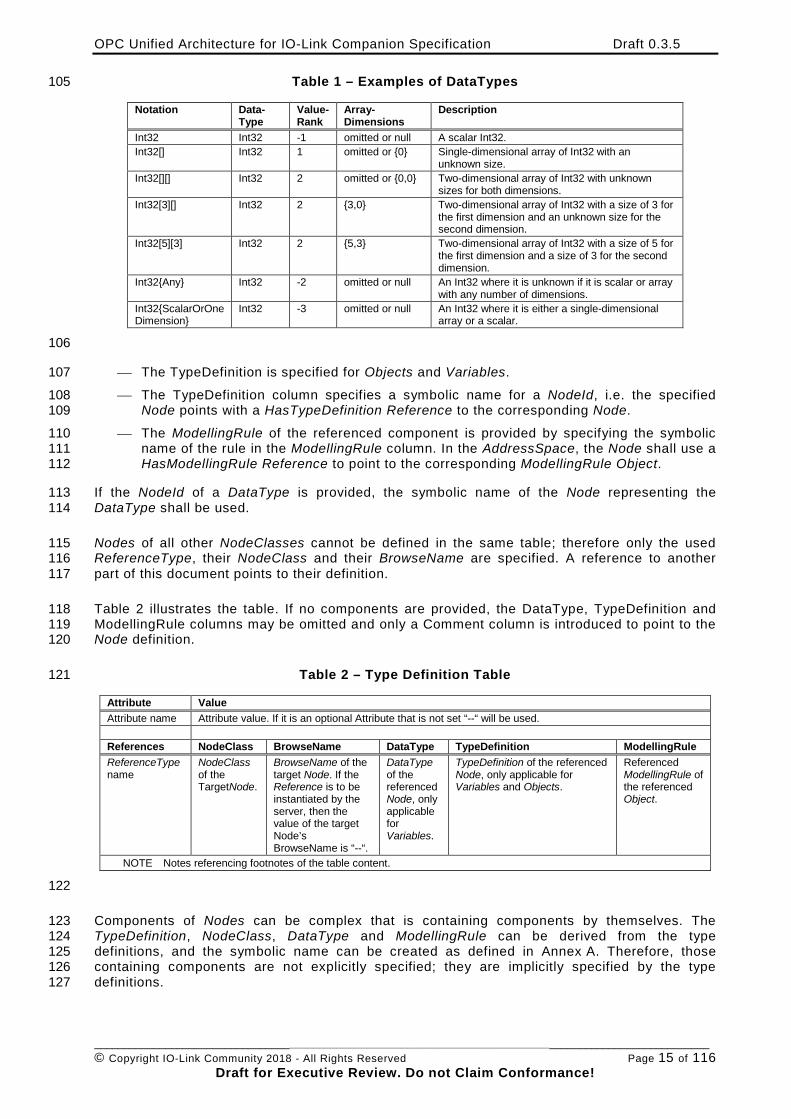
Table 1 – Examples of DataTypes 105
Notation Data-Type
Value-Rank
Array-Dimensions
Description
Int32 Int32 -1 omitted or null A scalar Int32. Int32[] Int32 1 omitted or {0} Single-dimensional array of Int32 with an
unknown size. Int32[][] Int32 2 omitted or {0,0} Two-dimensional array of Int32 with unknown
sizes for both dimensions. Int32[3][] Int32 2 {3,0} Two-dimensional array of Int32 with a size of 3 for
the first dimension and an unknown size for the second dimension.
Int32[5][3] Int32 2 {5,3} Two-dimensional array of Int32 with a size of 5 for the first dimension and a size of 3 for the second dimension.
Int32{Any} Int32 -2 omitted or null An Int32 where it is unknown if it is scalar or array with any number of dimensions.
Int32{ScalarOrOneDimension}
Int32 -3 omitted or null An Int32 where it is either a single-dimensional array or a scalar.
106
The TypeDefinition is specified for Objects and Variables. 107
The TypeDefinition column specifies a symbolic name for a NodeId, i.e. the specified 108 Node points with a HasTypeDefinition Reference to the corresponding Node. 109
The ModellingRule of the referenced component is provided by specifying the symbolic 110 name of the rule in the ModellingRule column. In the AddressSpace, the Node shall use a 111 HasModellingRule Reference to point to the corresponding ModellingRule Object. 112
If the NodeId of a DataType is provided, the symbolic name of the Node representing the 113 DataType shall be used. 114
Nodes of all other NodeClasses cannot be defined in the same table; therefore only the used 115 ReferenceType, their NodeClass and their BrowseName are specified. A reference to another 116 part of this document points to their definition. 117
Table 2 illustrates the table. If no components are provided, the DataType, TypeDefinition and 118 ModellingRule columns may be omitted and only a Comment column is introduced to point to the 119 Node definition. 120
Table 2 – Type Definition Table 121
Attribute Value Attribute name Attribute value. If it is an optional Attribute that is not set “--“ will be used. References NodeClass BrowseName DataType TypeDefinition ModellingRule ReferenceType name
NodeClass of the TargetNode.
BrowseName of the target Node. If the Reference is to be instantiated by the server, then the value of the target Node’s BrowseName is “--“.
DataType of the referenced Node, only applicable for Variables.
TypeDefinition of the referenced Node, only applicable for Variables and Objects.
Referenced ModellingRule of the referenced Object.
NOTE Notes referencing footnotes of the table content.
122
Components of Nodes can be complex that is containing components by themselves. The 123 TypeDefinition, NodeClass, DataType and ModellingRule can be derived from the type 124 definitions, and the symbolic name can be created as defined in Annex A. Therefore, those 125 containing components are not explicitly specified; they are implicitly specified by the type 126 definitions. 127
OPC Unified Architecture for IO-Link Companion Specification Draft 0.3.5
________________________________________________________________________________________________________ © Copyright IO-Link Community 2018 - All Rights Reserved Page 16 of 116
Draft for Executive Review. Do not Claim Conformance!
3.4.2 NodeIds and BrowseNames 128
3.4.2.1 NodeIds 129
The NodeIds of all Nodes described in this standard are only symbolic names. Annex A defines 130 the actual NodeIds. 131
The symbolic name of each Node defined in this specification is its BrowseName, or, when it is 132 part of another Node, the BrowseName of the other Node, a “.”, and the BrowseName of itself. In 133 this case “part of” means that the whole has a HasProperty or HasComponent Reference to its 134 part. Since all Nodes not being part of another Node have a unique name in this specification, 135 the symbolic name is unique. 136
The NamespaceIndex for all NodeIds defined in this specification is defined in Annex A. The 137 namespace for this NamespaceIndex is vendor-specific and depends on the position of the 138 namespace URI in the server namespace table. 139
Note that this specification not only defines concrete Nodes, but also requires that some Nodes 140 shall be generated, for example one for each Session running on the Server. The NodeIds of 141 those Nodes are vendor-specific, including the Namespace. But the NamespaceIndex of those 142 Nodes cannot be the NamespaceIndex used for the Nodes defined in this specification, because 143 they are not defined by this specification but generated by the Server. 144
3.4.2.2 BrowseNames 145
The text part of the BrowseNames for all Nodes defined in this specification is specified in the 146 tables defining the Nodes. The NamespaceIndex for all BrowseNames defined in this 147 specification is defined in Annex A. 148
If the BrowseName is not defined by this specification, a namespace index prefix like 149 ‘0:EngineeringUnits’ is added to the BrowseName. This is typically necessary if a Property of 150 another specification is overwritten or used in the OPC UA types defined in this specification. 151 Table 78 provides a list of namespaces used in this specification. 152
3.4.3 Common Attributes 153
3.4.3.1 General 154
The Attributes of Nodes, their DataTypes and descriptions are defined in OPC UA Part 3. 155 Attributes not marked as optional are mandatory and shall be provided by a Server. The 156 following tables define if the Attribute value is defined by this specification or if it is vendor-157 specific. 158
For all Nodes specified in this specification, the Attributes named in Table 3 shall be set as 159 specified in the table. 160
OPC Unified Architecture for IO-Link Companion Specification Draft 0.3.5
________________________________________________________________________________________________________ © Copyright IO-Link Community 2018 - All Rights Reserved Page 17 of 116
Draft for Executive Review. Do not Claim Conformance!
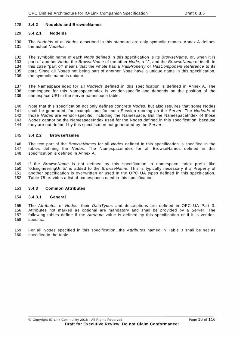
Table 3 – Common Node Attributes 161
Attribute Value DisplayName The DisplayName is a LocalizedText. Each server shall provide the DisplayName identical to
the BrowseName of the Node for the LocaleId “en”. Whether the server provides translated names for other LocaleIds is vendor-specific.
Description Optionally a vendor-specific description is provided. NodeClass Shall reflect the NodeClass of the Node. NodeId The NodeId is described by BrowseNames as defined in 3.4.2.1 WriteMask Optionally the WriteMask Attribute can be provided. If the WriteMask Attribute is provided, it
shall set all non-vendor-specific Attributes to not writable. For example, the Description Attribute may be set to writable since a Server may provide a vendor-specific description for the Node. The NodeId shall not be writable, because it is defined for each Node in this specification.
UserWriteMask Optionally the UserWriteMask Attribute can be provided. The same rules as for the WriteMask Attribute apply.
RolePermissions Optionally vendor-specific role permissions can be provided. UserRolePermissions Optionally the role permissions of the current Session can be provided. The value is vendor-
specific and depend on the RolePermissions Attribute (if provided) and the current Session. AccessRestrictions Optionally vendor-specific access restrictions can be provided.
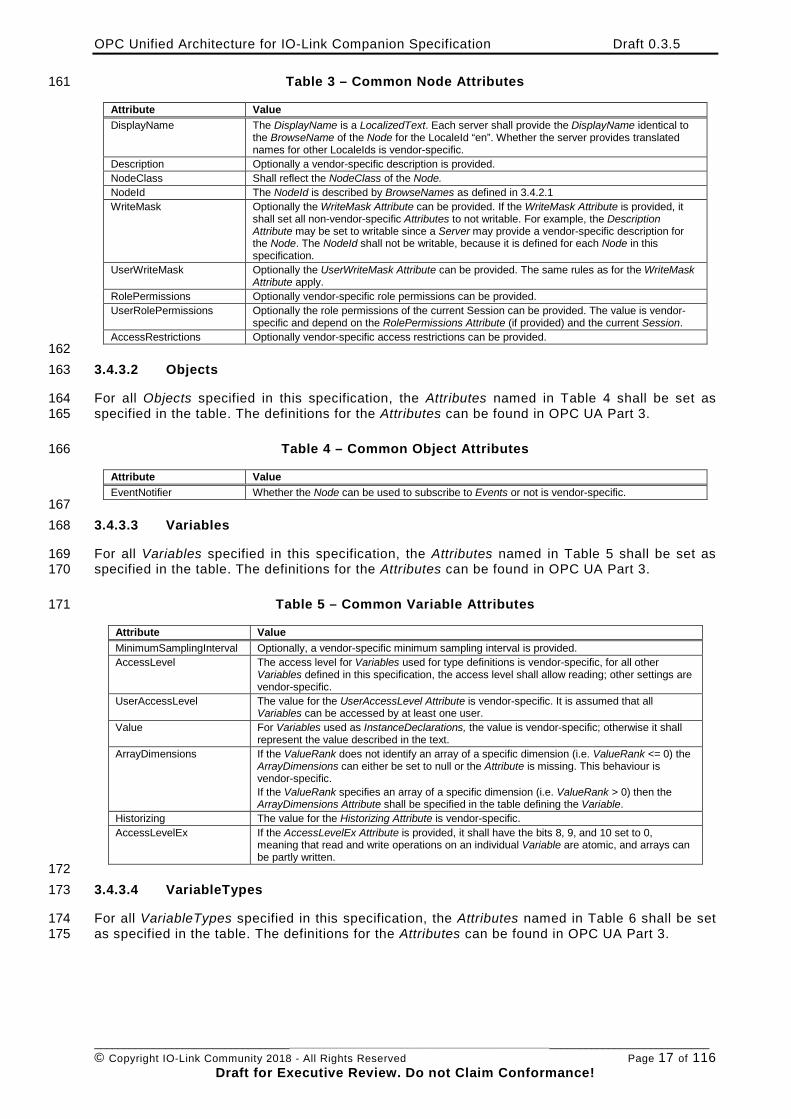
162 3.4.3.2 Objects 163
For all Objects specified in this specification, the Attributes named in Table 4 shall be set as 164 specified in the table. The definitions for the Attributes can be found in OPC UA Part 3. 165
Table 4 – Common Object Attributes 166
Attribute Value EventNotifier Whether the Node can be used to subscribe to Events or not is vendor-specific.
167 3.4.3.3 Variables 168
For all Variables specified in this specification, the Attributes named in Table 5 shall be set as 169 specified in the table. The definitions for the Attributes can be found in OPC UA Part 3. 170
Table 5 – Common Variable Attributes 171
Attribute Value MinimumSamplingInterval Optionally, a vendor-specific minimum sampling interval is provided. AccessLevel The access level for Variables used for type definitions is vendor-specific, for all other
Variables defined in this specification, the access level shall allow reading; other settings are vendor-specific.
UserAccessLevel The value for the UserAccessLevel Attribute is vendor-specific. It is assumed that all Variables can be accessed by at least one user.
Value For Variables used as InstanceDeclarations, the value is vendor-specific; otherwise it shall represent the value described in the text.
ArrayDimensions If the ValueRank does not identify an array of a specific dimension (i.e. ValueRank <= 0) the ArrayDimensions can either be set to null or the Attribute is missing. This behaviour is vendor-specific. If the ValueRank specifies an array of a specific dimension (i.e. ValueRank > 0) then the ArrayDimensions Attribute shall be specified in the table defining the Variable.
Historizing The value for the Historizing Attribute is vendor-specific. AccessLevelEx If the AccessLevelEx Attribute is provided, it shall have the bits 8, 9, and 10 set to 0,
meaning that read and write operations on an individual Variable are atomic, and arrays can be partly written.
172 3.4.3.4 VariableTypes 173
For all VariableTypes specified in this specification, the Attributes named in Table 6 shall be set 174 as specified in the table. The definitions for the Attributes can be found in OPC UA Part 3. 175
OPC Unified Architecture for IO-Link Companion Specification Draft 0.3.5
________________________________________________________________________________________________________ © Copyright IO-Link Community 2018 - All Rights Reserved Page 18 of 116
Draft for Executive Review. Do not Claim Conformance!
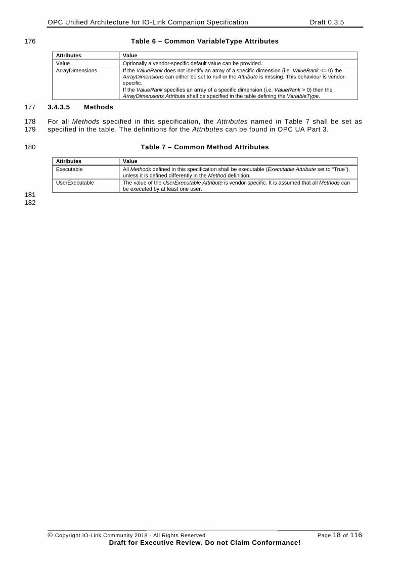
Table 6 – Common VariableType Attributes 176
Attributes Value Value Optionally a vendor-specific default value can be provided. ArrayDimensions If the ValueRank does not identify an array of a specific dimension (i.e. ValueRank <= 0) the
ArrayDimensions can either be set to null or the Attribute is missing. This behaviour is vendor-specific. If the ValueRank specifies an array of a specific dimension (i.e. ValueRank > 0) then the ArrayDimensions Attribute shall be specified in the table defining the VariableType.
3.4.3.5 Methods 177
For all Methods specified in this specification, the Attributes named in Table 7 shall be set as 178 specified in the table. The definitions for the Attributes can be found in OPC UA Part 3. 179
Table 7 – Common Method Attributes 180
Attributes Value Executable All Methods defined in this specification shall be executable (Executable Attribute set to “True”),
unless it is defined differently in the Method definition. UserExecutable The value of the UserExecutable Attribute is vendor-specific. It is assumed that all Methods can
be executed by at least one user. 181
182
OPC Unified Architecture for IO-Link Companion Specification Draft 0.3.5
________________________________________________________________________________________________________ © Copyright IO-Link Community 2018 - All Rights Reserved Page 19 of 116
Draft for Executive Review. Do not Claim Conformance!
4 General Information on IO-Link and OPC UA 183
4.1 Introduction to IO-Link 184
4.1.1 What is IO-Link? 185
IO-Link is the first standardized IO technology worldwide (IEC 61131-9) for the communication 186 with sensors and actuators. The powerful point-to-point communication is based on the long 187 established 3-wire sensor and actuator connection without additional requirements regarding the 188 cable material. So, IO-Link is no fieldbus but the further development of the existing, tried-and-189 tested connection technology for sensors and actuators. 190
4.1.2 Basics of IO-Link 191
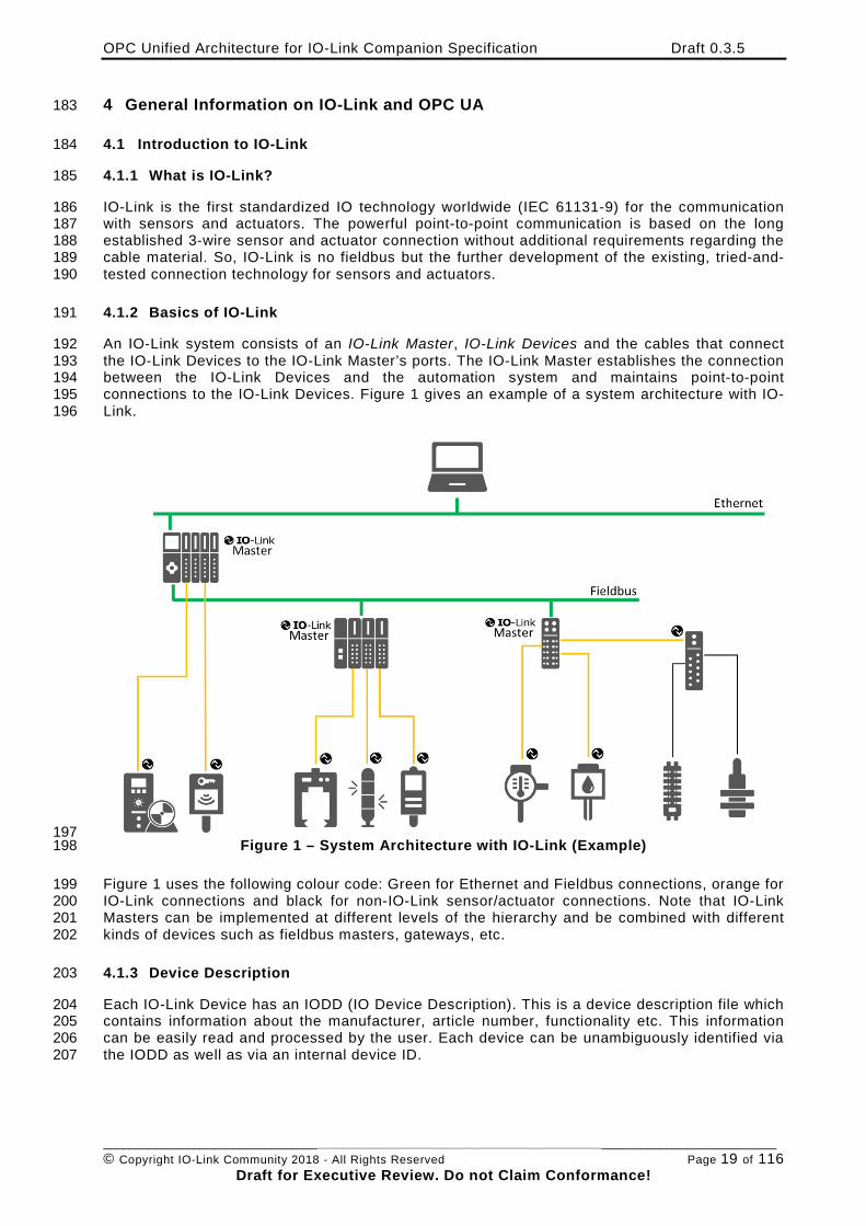
An IO-Link system consists of an IO-Link Master, IO-Link Devices and the cables that connect 192 the IO-Link Devices to the IO-Link Master’s ports. The IO-Link Master establishes the connection 193 between the IO-Link Devices and the automation system and maintains point-to-point 194 connections to the IO-Link Devices. Figure 1 gives an example of a system architecture with IO-195 Link. 196
197 Figure 1 – System Architecture with IO-Link (Example) 198
Figure 1 uses the following colour code: Green for Ethernet and Fieldbus connections, orange for 199 IO-Link connections and black for non-IO-Link sensor/actuator connections. Note that IO-Link 200 Masters can be implemented at different levels of the hierarchy and be combined with different 201 kinds of devices such as fieldbus masters, gateways, etc. 202
4.1.3 Device Description 203
Each IO-Link Device has an IODD (IO Device Description). This is a device description file which 204 contains information about the manufacturer, article number, functionality etc. This information 205 can be easily read and processed by the user. Each device can be unambiguously identified via 206 the IODD as well as via an internal device ID. 207
OPC Unified Architecture for IO-Link Companion Specification Draft 0.3.5
________________________________________________________________________________________________________ © Copyright IO-Link Community 2018 - All Rights Reserved Page 20 of 116
Draft for Executive Review. Do not Claim Conformance!
4.2 Introduction to OPC Unified Architecture 208
4.2.1 What is OPC UA? 209
OPC UA is an open and royalty free set of standards designed as a universal communication 210 protocol. While there are numerous communication solutions available, OPC UA has key 211 advantages: 212
• A state of art security model (see OPC UA Part 2). 213
• A fault tolerant communication protocol. 214
• An information modelling framework that allows application developers to represent their 215 data in a way that makes sense to them. 216
OPC UA has a broad scope which delivers for economies of scale for application developers. 217 This means that a larger number of high quality applications at a reasonable cost are available. 218 When combined with semantic models such as OPC UA for IO-Link, OPC UA makes it easier for 219 end users to access data via generic commercial applications. 220
The OPC UA model is scalable from small devices to ERP systems. OPC UA Servers process 221 information locally and then provide that data in a consistent format to any application requesting 222 data - ERP, MES, PMS, Maintenance Systems, HMI, Smartphone or a standard Browser, for 223 examples. For a more complete overview see OPC UA Part 1. 224
4.2.2 Basics of OPC UA 225
As an open standard, OPC UA is based on standard internet technologies, like TCP/IP, HTTP, 226 Web Sockets. 227
As an extensible standard, OPC UA provides a set of Services (see OPC UA Part 4) and a basic 228 information model framework. This framework provides an easy manner for creating and 229 exposing vendor defined information in a standard way. More importantly all OPC UA Clients are 230 expected to be able to discover and use vendor-defined information. This means OPC UA users 231 can benefit from the economies of scale that come with generic visualization and historian 232 applications. This specification is an example of an OPC UA Information Model designed to meet 233 the needs of developers and users. 234
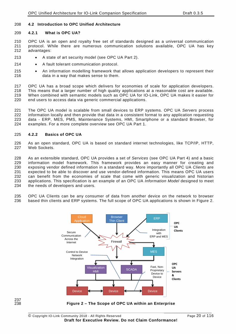
OPC UA Clients can be any consumer of data from another device on the network to browser 235 based thin clients and ERP systems. The full scope of OPC UA applications is shown in Figure 2. 236
BrowserThin Client
VisualizationHMI
Firewall
CloudApplication
SCADA
MES
ERP
Device DeviceDevice
Secure Communication
Across the Internet
Fast, Non-ProprietaryDevice to Device
Control to Device Network
Integration
Integration with
ERP and MES
htCUAClients
htCUAServers&Clients
237 Figure 2 – The Scope of OPC UA within an Enterprise 238
OPC Unified Architecture for IO-Link Companion Specification Draft 0.3.5
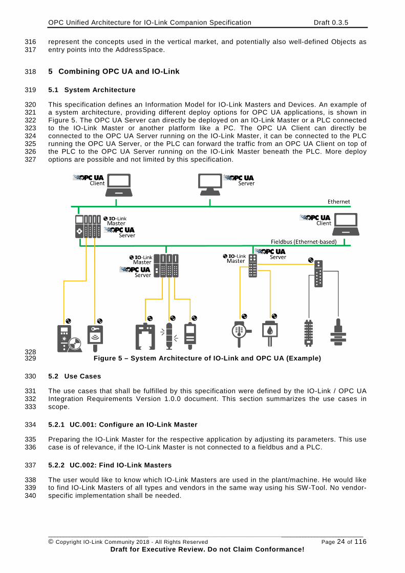
________________________________________________________________________________________________________ © Copyright IO-Link Community 2018 - All Rights Reserved Page 21 of 116
Draft for Executive Review. Do not Claim Conformance!
OPC UA provides a robust and reliable communication infrastructure having mechanisms for 239 handling lost messages, failover, heartbeat, etc. With its binary encoded data, it offers a high-240 performing data exchange solution. Security is built into OPC UA as security requirements 241 become more and more important especially since environments are connected to the office 242 network or the internet and attackers are starting to focus on automation systems. 243
4.2.3 Information Modelling in OPC UA 244
4.2.3.1 Concepts 245
OPC UA provides a framework that can be used to represent complex information as Objects in 246 an AddressSpace which can be accessed with standard services. These Objects consist of 247 Nodes connected by References. Different classes of Nodes convey different semantics. For 248 example, a Variable Node represents a value that can be read or written. The Variable Node has 249 an associated DataType that can define the actual value, such as a string, float, structure etc. It 250 can also describe the Variable value as a variant. A Method Node represents a function that can 251 be called. Every Node has a number of Attributes including a unique identifier called a NodeId 252 and non-localized name called as BrowseName. 253
Object and Variable Nodes represent instances and they always reference a TypeDefinition 254 (ObjectType or VariableType) Node which describes their semantics and structure. Figure 3 255 illustrates the relationship between an instance and its TypeDefinition. 256
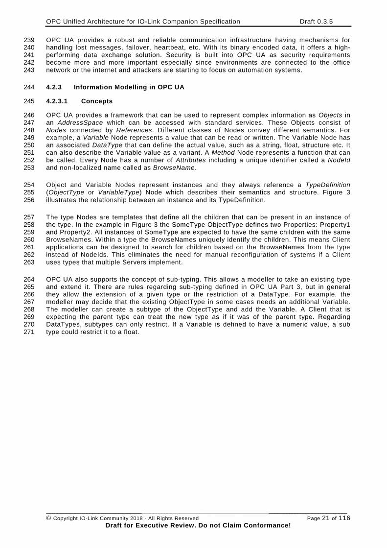
The type Nodes are templates that define all the children that can be present in an instance of 257 the type. In the example in Figure 3 the SomeType ObjectType defines two Properties: Property1 258 and Property2. All instances of SomeType are expected to have the same children with the same 259 BrowseNames. Within a type the BrowseNames uniquely identify the children. This means Client 260 applications can be designed to search for children based on the BrowseNames from the type 261 instead of NodeIds. This eliminates the need for manual reconfiguration of systems if a Client 262 uses types that multiple Servers implement. 263
OPC UA also supports the concept of sub-typing. This allows a modeller to take an existing type 264 and extend it. There are rules regarding sub-typing defined in OPC UA Part 3, but in general 265 they allow the extension of a given type or the restriction of a DataType. For example, the 266 modeller may decide that the existing ObjectType in some cases needs an additional Variable. 267 The modeller can create a subtype of the ObjectType and add the Variable. A Client that is 268 expecting the parent type can treat the new type as if it was of the parent type. Regarding 269 DataTypes, subtypes can only restrict. If a Variable is defined to have a numeric value, a sub 270 type could restrict it to a float. 271
OPC Unified Architecture for IO-Link Companion Specification Draft 0.3.5
________________________________________________________________________________________________________ © Copyright IO-Link Community 2018 - All Rights Reserved Page 22 of 116
Draft for Executive Review. Do not Claim Conformance!
272 Figure 3 – The Relationship between Type Definitions and Instances 273
References allow Nodes to be connected in ways that describe their relationships. All 274 References have a ReferenceType that specifies the semantics of the relationship. References 275 can be hierarchical or non-hierarchical. Hierarchical references are used to create the structure 276 of Objects and Variables. Non-hierarchical are used to create arbitrary associations. Applications 277 can define their own ReferenceType by creating subtypes of an existing ReferenceType. 278 Subtypes inherit the semantics of the parent but may add additional restrictions. 279
4.2.3.2 Graphical Notation 280
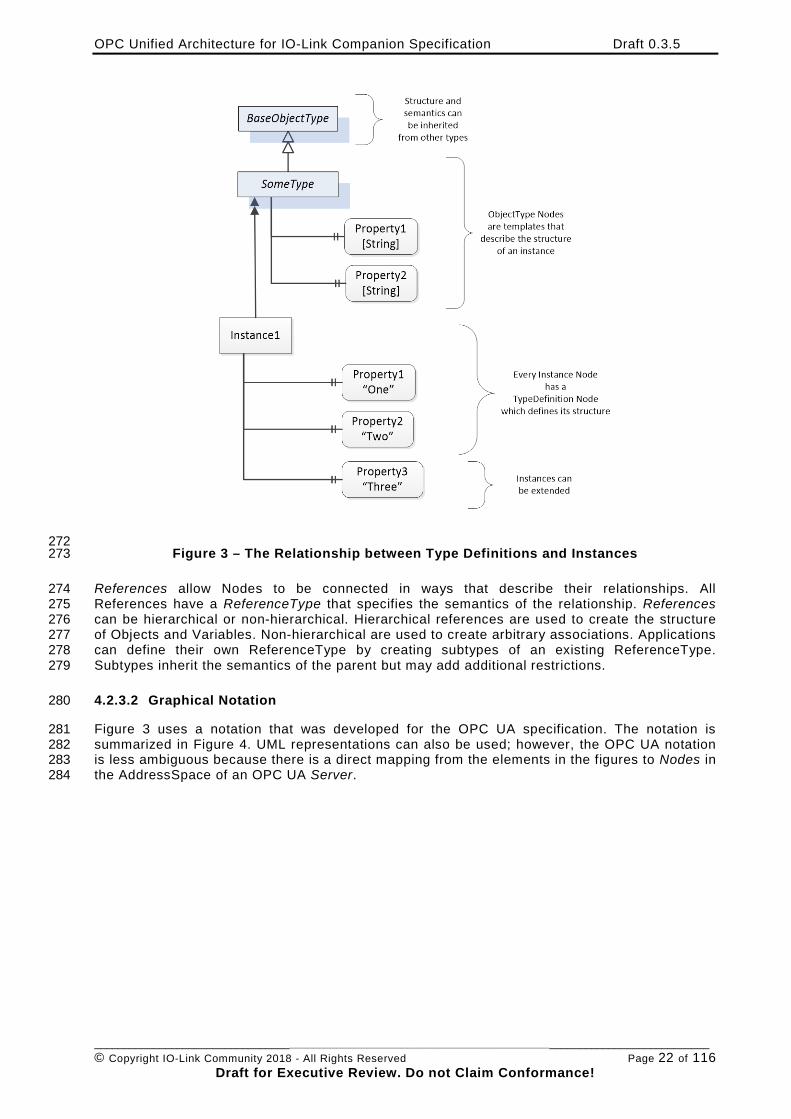
Figure 3 uses a notation that was developed for the OPC UA specification. The notation is 281 summarized in Figure 4. UML representations can also be used; however, the OPC UA notation 282 is less ambiguous because there is a direct mapping from the elements in the figures to Nodes in 283 the AddressSpace of an OPC UA Server. 284
OPC Unified Architecture for IO-Link Companion Specification Draft 0.3.5
________________________________________________________________________________________________________ © Copyright IO-Link Community 2018 - All Rights Reserved Page 23 of 116
Draft for Executive Review. Do not Claim Conformance!
285 Figure 4 – The OPC UA Information Model Notation 286
A complete description of the different types of Nodes and References can be found in OPC UA 287 Part 3 and the base structure is described in OPC UA Part 5. 288
4.2.4 OPC UA Profiles 289
OPC UA specification defines a very wide range of functionality in its basic information model. It 290 is not expected that all Clients or Servers support all functionality in the OPC UA specifications. 291 OPC UA includes the concept of Profiles, which segment the functionality into testable certifiable 292 units. This allows the definition of functional subsets (that are expected to be implemented) 293 within a companion specification. The Profiles do not restrict functionality, but generate 294 requirements for a minimum set of functionalities (see OPC UA Part 7). 295
4.2.5 Namespaces 296
OPC UA allows information from many different sources to be combined into a single coherent 297 AddressSpace. Namespaces are used to make this possible by eliminating naming and id 298 conflicts between information from different sources. Namespaces in OPC UA have a globally 299 unique string called a NamespaceUri and a locally unique integer called a NamespaceIndex. The 300 NamespaceIndex is only unique within the context of a Session between an OPC UA Client and 301 an OPC UA Server. The Services defined for OPC UA use the NamespaceIndex to specify the 302 Namespace for qualified values. 303
There are two types of values in OPC UA that are qualified with Namespaces: NodeIds and 304 QualifiedNames. NodeIds are globally unique identifiers for Nodes. This means the same Node 305 with the same NodeId can appear in many Servers. This, in turn, means Clients can have built in 306 knowledge of some Nodes. OPC UA Information Models generally define globally unique 307 NodeIds for the TypeDefinitions defined by the Information Model. 308
QualifiedNames are non-localized names qualified with a Namespace. They are used for the 309 BrowseNames of Nodes and allow the same names to be used by different information models 310 without conflict. TypeDefinitions are not allowed to have children with duplicate BrowseNames; 311 however, instances do not have that restriction. 312
4.2.6 Companion Specifications 313
An OPC UA companion specification for an industry specific vertical market describes an 314 Information Model by defining ObjectTypes, VariableTypes, DataTypes and ReferenceTypes that 315
OPC Unified Architecture for IO-Link Companion Specification Draft 0.3.5
________________________________________________________________________________________________________ © Copyright IO-Link Community 2018 - All Rights Reserved Page 24 of 116
Draft for Executive Review. Do not Claim Conformance!
represent the concepts used in the vertical market, and potentially also well-defined Objects as 316 entry points into the AddressSpace. 317
5 Combining OPC UA and IO-Link 318
5.1 System Architecture 319
This specification defines an Information Model for IO-Link Masters and Devices. An example of 320 a system architecture, providing different deploy options for OPC UA applications, is shown in 321 Figure 5. The OPC UA Server can directly be deployed on an IO-Link Master or a PLC connected 322 to the IO-Link Master or another platform like a PC. The OPC UA Client can directly be 323 connected to the OPC UA Server running on the IO-Link Master, it can be connected to the PLC 324 running the OPC UA Server, or the PLC can forward the traffic from an OPC UA Client on top of 325 the PLC to the OPC UA Server running on the IO-Link Master beneath the PLC. More deploy 326 options are possible and not limited by this specification. 327
328 Figure 5 – System Architecture of IO-Link and OPC UA (Example) 329
5.2 Use Cases 330
The use cases that shall be fulfilled by this specification were defined by the IO-Link / OPC UA 331 Integration Requirements Version 1.0.0 document. This section summarizes the use cases in 332 scope. 333
5.2.1 UC.001: Configure an IO-Link Master 334
Preparing the IO-Link Master for the respective application by adjusting its parameters. This use 335 case is of relevance, if the IO-Link Master is not connected to a fieldbus and a PLC. 336
5.2.2 UC.002: Find IO-Link Masters 337
The user would like to know which IO-Link Masters are used in the plant/machine. He would like 338 to find IO-Link Masters of all types and vendors in the same way using his SW-Tool. No vendor-339 specific implementation shall be needed. 340
OPC Unified Architecture for IO-Link Companion Specification Draft 0.3.5
________________________________________________________________________________________________________ © Copyright IO-Link Community 2018 - All Rights Reserved Page 25 of 116
Draft for Executive Review. Do not Claim Conformance!
5.2.3 UC.003: Find IO-Link Devices 341
To be able to parameterize the connected IO-Link Devices it must be possible to request the IO-342 Link Master to give the information about connected devices to each of its ports. 343
5.2.4 UC.004: Initial commissioning of IO-Link Device 344
The user wants to parameterize the IO-Link Device for its application. 345
5.2.5 UC.005: Configure device metadata 346
Add metadata to identify the role and position of a device in the machine or process. If the IO-347 Link Device does not support the IO-Link Common Profile with Application Specific Tag, Function 348 Tag and Location Tag, these parameters shall be virtually provided in the OPC UA Server. 349
5.2.6 UC.006: Configure IO-Link subscriptions 350
Setup data subscriptions to master or device variables and events to be able to: 351
• Calculate operation KPIs (e.g. OEE) 352
• Generate SPC (statistical process control) charts 353
• Measure process data for process optimization 354
5.2.7 UC.007: Disconnection of IO-Link Device 355
The user (OPC UA Client) gets informed that a certain subscription is not available anymore, i.e. 356 due to a disconnected IO-Link Device, to identify reasons for gaps in logs. 357
5.2.8 UC.008: Read-product identification 358
The user of an OPC UA Client can uniquely identify all connected IO-Link Masters by their serial 359 number information and devices by vendor and device ID to recognize the status of the devices 360 and facilitate the exchange. For each IO-Link Device and the IO-Link Master, the following data 361 are provided for reading only: 362
• IO-Link DeviceType Version (mandatory) 363
• IO-Link Protocol Version (mandatory) 364
• Vendor Name (mandatory) 365
• Product Name (mandatory) 366
• Product ID (mandatory) 367
• Serial Number (mandatory) 368
• Hardware Revision (optional) 369
• Software Revision (optional) 370
• Vendor Text (optional) 371
• Product Text (optional) 372
• Application Specific Tag (mandatory – see UC.005) 373
• Function Tag (optional) 374
• Location Tag (optional) 375
• Implicit topology information (address of IO-Link Master and port number, where the IO-376 Link Device is connected to) 377
5.2.9 UC.009: Read diagnostics data 378
User shall have access to logged diagnosis events. General and specific access to diagnostic 379 data after authorization. OPC UA Client may collect event information sent to him in a logging 380
OPC Unified Architecture for IO-Link Companion Specification Draft 0.3.5
________________________________________________________________________________________________________ © Copyright IO-Link Community 2018 - All Rights Reserved Page 26 of 116
Draft for Executive Review. Do not Claim Conformance!
buffer. If the IO-Link Master provides event logging, this information should be accessible via 381 OPC UA. 382
5.2.10 UC.010: Read operating and failure statistics 383
The maintenance staff would like to use the productivity of used devices to determine the 384 characteristics of the device during the period of use and the number of failures to obtain a 385 statement about plant availability. 386
The maintenance staffs receive data on the operating time and the failure times of the connected 387 devices. 388
The data are generated in the IO-Link Master and updated on the OPC UA Server. 389
The IO-Link Master records for each connected IO-Link Device 390
• the duration the device is connected 391
• the duration the device has communicated without error 392
• the duration the device was not communicable 393
• how often the device has been plugged in 394
• how often the device has been changed 395
• how often the device was not accessible 396
The master cyclically updates the data on the OPC UA Server and stores it in a fail-safe manner. 397
• The data has a resolution in seconds. 398
• The duration refers to the time of the last reset (usually during commissioning). 399
5.2.11 UC.011: Reset operating and failure statistics 400
The maintenance staff can reset the operating and failure statistics. 401
5.2.12 UC.012: Optimize machine settings 402
A machine in production needs to be optimized. This can be done by changing parameters of IO-403 Link Devices (e.g. limit values). 404
5.2.13 UC.013: Plant and machine status supervision 405
The operator staff would like to get immediately informed by the machine regarding process 406 productivity and plant availability. In case of degradation, the possible location or source of 407 problem shall also be reported. 408
Every plant subsystem with OPC UA Server connectivity sends an event if a critical condition has 409 been detected or a configured threshold has been reached. The subsystem can also contain IO-410 Link Master and Devices, where IO-Link Events are translated into OPC UA events. The reported 411 events from these subsystems shall consist of: 412
• the origin identity of the event 413
• the unambiguous identity of the event 414
• the absolute time of occurrence according to the subsystems time base 415
• if the occurrence is temporal, the duration of the erroneous condition 416
• if possible the identity of the processed item 417
On the application level, the following is derived on this raw data: 418
• an availability signal in traffic light encoding 419
OPC Unified Architecture for IO-Link Companion Specification Draft 0.3.5
________________________________________________________________________________________________________ © Copyright IO-Link Community 2018 - All Rights Reserved Page 27 of 116
Draft for Executive Review. Do not Claim Conformance!
• notification towards the operator staff 420
5.2.14 UC.014: Faulty device replacement 421
The user would like to replace an IO-Link Master or IO-Link Device with transfer of the previous 422 configuration to the new device. 423
5.2.15 UC.015: Firmware update 424
Update device firmware individually and in groups of identical devices for IO-Link Masters and 425 IO-Link Devices. 426
5.2.16 UC.016: Asset Management 427
Manage all the assets in an automation network. 428
Maintenance staff is called to adjust one or more settings. 429
5.2.17 UC.017: Cloud-connectivity at Edge Gateway 430
For Industry 4.0 application, an OPC UA Server will be the virtual interface between the cloud 431 and the sensors in the field. 432
Therefore, the OPC UA Server has to apply the following functions: 433
• Find all IO-Link Masters 434
• Find IO-Link Devices 435
• Download IODD of connected devices 436
• Build up information model 437
• Record all replacement of connected devices and update information model 438
• Capture the status of connected devices 439
• Read cyclic IO data 440
• Read ISDU parameter sets 441
The Edge Gateway must find IO-Link Masters of all types and vendors in the same way. No 442 vendor-specific implementation shall be necessary. 443
6 IO-Link Information Model Overview 444
6.1 Modelling Concepts 445
6.1.1 IO-Link Master 446
The configuration of the IO-Link Master is done by representing the IO-Link Master as Object 447 having several Variables and Methods to view and to change the configuration. The ports of the 448 IO-Link Master are modelled as individual Objects. 449
6.1.2 IO-Link Port 450
The configuration of an IO-Link Port is done by representing the IO-Link Port as Object having 451 several Variables and Methods to view and to change the configuration. If the IO-Link Port has a 452 connected or configured IO-Link Device, the device is referenced from the IO-Link Port. 453
6.1.3 IO-Link Device 454
The IO-Link Device is represented as Object having several Variables and Methods to view and 455 to change the configuration. There is a generic ObjectType representing the common 456
OPC Unified Architecture for IO-Link Companion Specification Draft 0.3.5
________________________________________________________________________________________________________ © Copyright IO-Link Community 2018 - All Rights Reserved Page 28 of 116
Draft for Executive Review. Do not Claim Conformance!
functionality of an IO-Link Device, and subtypes of it for the IODD extensions describing the type 457 of a specific IO-Link Device in more detail and providing more intuitive configuration options. 458
6.1.4 IO-Link Events 459
Events can occur for different reasons. An IO-Link Master can generate vendor-specific Events; 460 an IO-Link Port generates Events when the communication to the device fails, the device gets 461 exchanged, etc. 462
The IO-Link Device itself provides event information. The IO-Link Master shall observe the event 463 flag provided with each message. In case it is set, the IO-Link Master shall receive the event 464 information via the acyclic communication mechanisms of IO-Link and forward it to the OPC UA 465 Server and the server provides the received events via the OPC UA interface. 466
Events provided as IO-Link “Error” or “Warning” are mapped to OPC UA Alarms (see OPC UA 467 Part 9), events provided as IO-Link “Notification” as OPC UA Events. 468
Additional to the observation of the event flag there is the possibility to get information about the 469 status of a stateful IO-Link Event (that is mapped to OPC UA Alarms) by using the DiagEntries of 470 PortStatusList as defined in the SMI (see IO-Link Addendum) and the DetailedDeviceStatus 471 (ISDU Index 0x0025). 472
6.1.5 Block operations: Up- and Download 473
An IO-Link Device can be configured by writing ISDU parameters. When a parameter of an IO-474 Link Device is written, the content is checked for consistency. This is useful, because it can 475 happen that certain value combinations of some parameters are not valid configuration options. 476
When a single parameter is written, its value is checked against the other parameters that were 477 configured before (or had this value by default). If the check fails, an error is returned. This 478 behavior causes problems if you want to change set of interdependent parameters. 479
Because of this, IO-Link provides block operations. If a device is set into the download state (via 480 a system command) the device allows to write many parameters to the device without checking 481 for consistency. When the block parameterization is finished (by sending another system 482 command) the consistency of all changed parameters is checked as a whole. If all parameters 483 are consistent, all changes are accepted, else all changes are rejected. 484
If the block operations are used to read several parameters, the device does not allow 485 parameters to be changed during this time. 486
The needed IO-Link system commands (see IO-Link Specification) are mapped to OPC UA 487 Methods. 488
To avoid concurrent access from different OPC UA Clients while the block operation is used by 489 one OPC UA Client, the OPC UA Client should lock the IO-Link Device using the Lock Object 490 defined in OPC UA Part 100. 491
6.1.6 Managing IODDs 492
IODDs are managed as ObjectTypes in the server. A specific, well-defined Object called 493 IODDManagement having well-defined Methods is used to load new IODDs to the Server (and 494 thereby creating new ObjectTypes) or to delete IODDs from the Server. 495
6.1.7 Relating IO-Link Devices to IO-Link Ports 496
Depending on the configuration of an IO-Link Port and whether a physical IO-Link Device is 497 connected to the IO-Link Port, either an Object representing the IO-Link Device is connected to 498
OPC Unified Architecture for IO-Link Companion Specification Draft 0.3.5
________________________________________________________________________________________________________ © Copyright IO-Link Community 2018 - All Rights Reserved Page 29 of 116
Draft for Executive Review. Do not Claim Conformance!
the IO-Link Port or not. The following state machine describes, whether such an Object is there, 499 and what ObjectType is used. 500
The top-level state machine defines the states “Port not configured as IO-Link” and “Select 501 Device Instance Type”. In the first state the IO-Link Port is configured that no IO-Link Device is 502 used (PortMode is either DEACTIVATED, DI_C/Q or DO_C/Q) and the optional Device Object is 503 not available. In the second state the IO-Link-Port is configured to be an IO-Link Device 504 (PortMode is either IOL_AUTOSTART or IOL_MANUAL) and the substates indicate whether a 505 Device Object exists as well as the used ObjectType. Changes of the PortMode trigger 506 transitions between the states. For the second state, additional transitions are defined that 507 trigger the reentrance of the state and thus the reevaluation whether a Device Object exists as 508 well as the used ObjectType. Those transitions include plugging in or off devices, changing the 509 UseIODD Property or changes of IO-Link Port configuration Parameters. 510
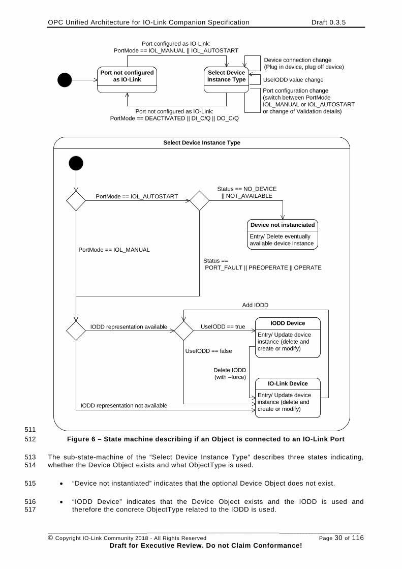
OPC Unified Architecture for IO-Link Companion Specification Draft 0.3.5
________________________________________________________________________________________________________ © Copyright IO-Link Community 2018 - All Rights Reserved Page 30 of 116
Draft for Executive Review. Do not Claim Conformance!
Select Device Instance Type
Port not configuredas IO-Link
Select DeviceInstance Type
Port configured as IO-Link:PortMode == IOL_MANUAL || IOL_AUTOSTART
Port not configured as IO-Link:PortMode == DEACTIVATED || DI_C/Q || DO_C/Q
Device connection change(Plug in device, plug off device)
UseIODD value change
Port configuration change(switch between PortModeIOL_MANUAL or IOL_AUTOSTARTor change of Validation details)
PortMode == IOL_AUTOSTART
Device not instanciated
Entry/ Delete eventuallyavailable device instance
Status == NO_DEVICE || NOT_AVAILABLE
PortMode == IOL_MANUAL
Status == PORT_FAULT || PREOPERATE || OPERATE
IODD Device
Entry/ Update deviceinstance (delete andcreate or modify)
IO-Link Device
Entry/ Update deviceinstance (delete andcreate or modify)
IODD representation available UseIODD == true
UseIODD == false
Delete IODD (with –force)
IODD representation not available
Add IODD
511 Figure 6 – State machine describing if an Object is connected to an IO-Link Port 512
The sub-state-machine of the “Select Device Instance Type” describes three states indicating, 513 whether the Device Object exists and what ObjectType is used. 514
• “Device not instantiated” indicates that the optional Device Object does not exist. 515
• “IODD Device” indicates that the Device Object exists and the IODD is used and 516 therefore the concrete ObjectType related to the IODD is used. 517
OPC Unified Architecture for IO-Link Companion Specification Draft 0.3.5
________________________________________________________________________________________________________ © Copyright IO-Link Community 2018 - All Rights Reserved Page 31 of 116
Draft for Executive Review. Do not Claim Conformance!
• “IO-Link Device” indicates that the Device Object exists and the IOLinkDeviceType is 518 used. 519
The sub-state-machine defines different choices to find the correct state. 520
When the PortMode is IOL_AUTOSTART but no device is connected, the “Device not 521 instantiated” state is used. 522
When the PortMode is IOL_AUTOSTART and a device is connected, or the PortMode is 523 IOL_MANUAL it is further decided if the “IODD Device” or the “IO-Link Device” state is used. 524
When the IODD representing the IO-Link Device is available in the server and the UseIODD 525 Parameter is “True”, the “IODD Device” state is used, otherwise the “IO-Link Device” state is 526 used. 527
Note that if an IO-Link Device is connected, the information of the connected IO-Link Device is 528 used to identify the IODD, even if the IO-Link Port has a different device configured (Status = 529 INCORRECT_DEVICE). Only when the PortMode is IOL_MANUAL and no device is connected 530 (Status == NO_DEVICE || NOT_AVAILABLE) the configured device information is used to 531 identify the IODD. 532
When the IO-Link Port is in the “IODD Device” state and the IODD is deleted (e.g. by the Method 533 RemoveIODD using the force option) it changes to the “IO-Link Device” state. 534
When the IO-Link Port is in the “IO-Link Device” state and the IODD representing the IO-Link 535 Device is added to the server (e.g. by the Method TransferIODD) and the UseIODD Parameter is 536 “True” it changes to the “IODD Device” state. 537
Note that there can be limitations on what Variables can be accessed and what Methods can be 538 executed from the Device Object (states “IO-Link Device” or “IODD Device”). 539
• When the PortMode is IOL_MANUAL and no device is connected (Status == NO_DEVICE 540 || NOT_AVAILABLE) the Device Object is available so OPC UA Clients can already be 541 configured to use the configured IO-Link Device, but since no physical IO-Link Device is 542 connected, all access to Variables or Methods requiring device access will fail (bad 543 code). Providing the structure of the configured IO-Link Device is especially helpful if an 544 IODD is used, since the structure defined by the IODD is already available to the OPC 545 UA Client (specific Parameters etc.). 546
• When the PortMode is IOL_MANUAL but the incorrect IO-Link Device is connected 547 (Status == INCORRECT_DEVICE) accessing the Variables representing the process data 548 (e.g. ProcessDataInput, ProcessDataOutput) will fail (bad code). 549
6.2 Model Overview 550 551 Editor note: 552 There are currently discussions in the OPC UA for Devices working group how best 553 to model several information models having different views on the same device (like 554 an IO-Link master can also be a Profinet slave). Depending on the outcome the 555 supertype of the IOLinkMasterType might change. We expect the basic structure 556 (ParameterSet etc.) to stay the same. 557
In Figure 7 an overview of the IO-Link Information Model is given. The IOLinkDeviceType 558 represents IO-Link Devices. In case no IODD is available, this type shall directly be used to 559 represent an IO-Link Device. If an IODD is available, a subtype is used representing the 560 concrete IODD and providing the additional parameters, system commands, etc. defined in the 561 IODD (see section 7.3). The IOLinkDeviceType inherits from DeviceType defined in OPC UA Part 562 100 and thus provides basic grouping mechanisms (ParameterSet for parameters and MethodSet 563 for Methods) as well as basic Properties of a device like SerialNumber. Section 7.1 defines 564
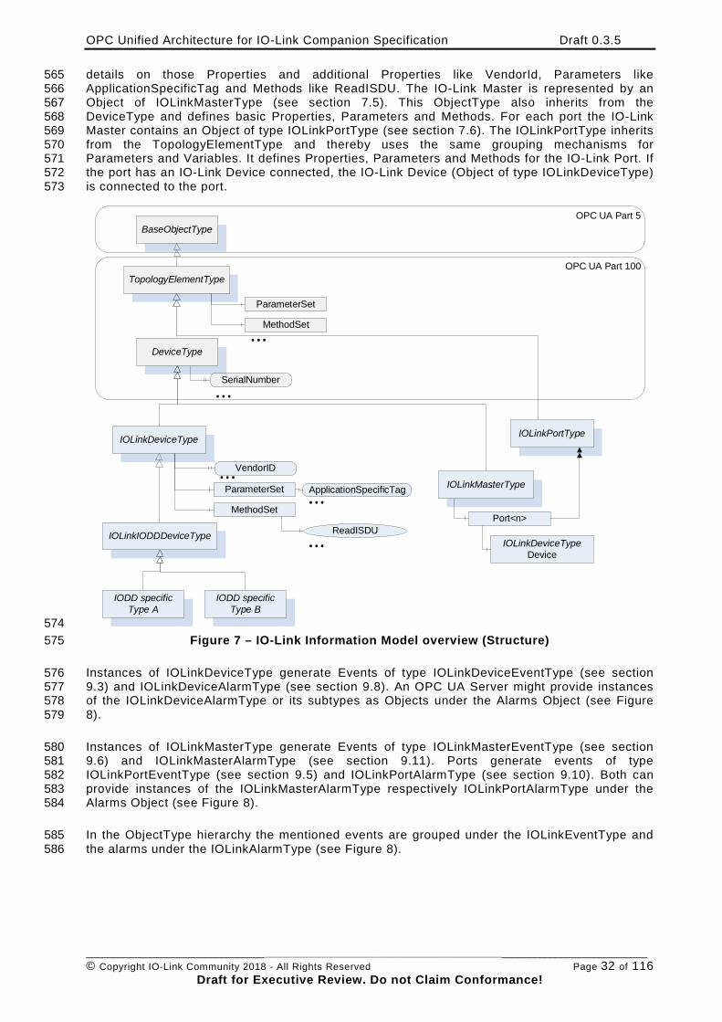
OPC Unified Architecture for IO-Link Companion Specification Draft 0.3.5
________________________________________________________________________________________________________ © Copyright IO-Link Community 2018 - All Rights Reserved Page 32 of 116
Draft for Executive Review. Do not Claim Conformance!
details on those Properties and additional Properties like VendorId, Parameters like 565 ApplicationSpecificTag and Methods like ReadISDU. The IO-Link Master is represented by an 566 Object of IOLinkMasterType (see section 7.5). This ObjectType also inherits from the 567 DeviceType and defines basic Properties, Parameters and Methods. For each port the IO-Link 568 Master contains an Object of type IOLinkPortType (see section 7.6). The IOLinkPortType inherits 569 from the TopologyElementType and thereby uses the same grouping mechanisms for 570 Parameters and Variables. It defines Properties, Parameters and Methods for the IO-Link Port. If 571 the port has an IO-Link Device connected, the IO-Link Device (Object of type IOLinkDeviceType) 572 is connected to the port. 573
BaseObjectType
TopologyElementType
DeviceType
IOLinkDeviceType
IODD specific Type A
IODD specific Type B
IOLinkMasterType
MethodSet
ParameterSet
SerialNumber
MethodSet
ParameterSet ApplicationSpecificTag
VendorID
ReadISDU
...
...
......
...
OPC UA Part 5
OPC UA Part 100
IOLinkPortType
Port<n>
IOLinkDeviceTypeDevice
IOLinkIODDDeviceType
574 Figure 7 – IO-Link Information Model overview (Structure) 575
Instances of IOLinkDeviceType generate Events of type IOLinkDeviceEventType (see section 576 9.3) and IOLinkDeviceAlarmType (see section 9.8). An OPC UA Server might provide instances 577 of the IOLinkDeviceAlarmType or its subtypes as Objects under the Alarms Object (see Figure 578 8). 579
Instances of IOLinkMasterType generate Events of type IOLinkMasterEventType (see section 580 9.6) and IOLinkMasterAlarmType (see section 9.11). Ports generate events of type 581 IOLinkPortEventType (see section 9.5) and IOLinkPortAlarmType (see section 9.10). Both can 582 provide instances of the IOLinkMasterAlarmType respectively IOLinkPortAlarmType under the 583 Alarms Object (see Figure 8). 584
In the ObjectType hierarchy the mentioned events are grouped under the IOLinkEventType and 585 the alarms under the IOLinkAlarmType (see Figure 8). 586
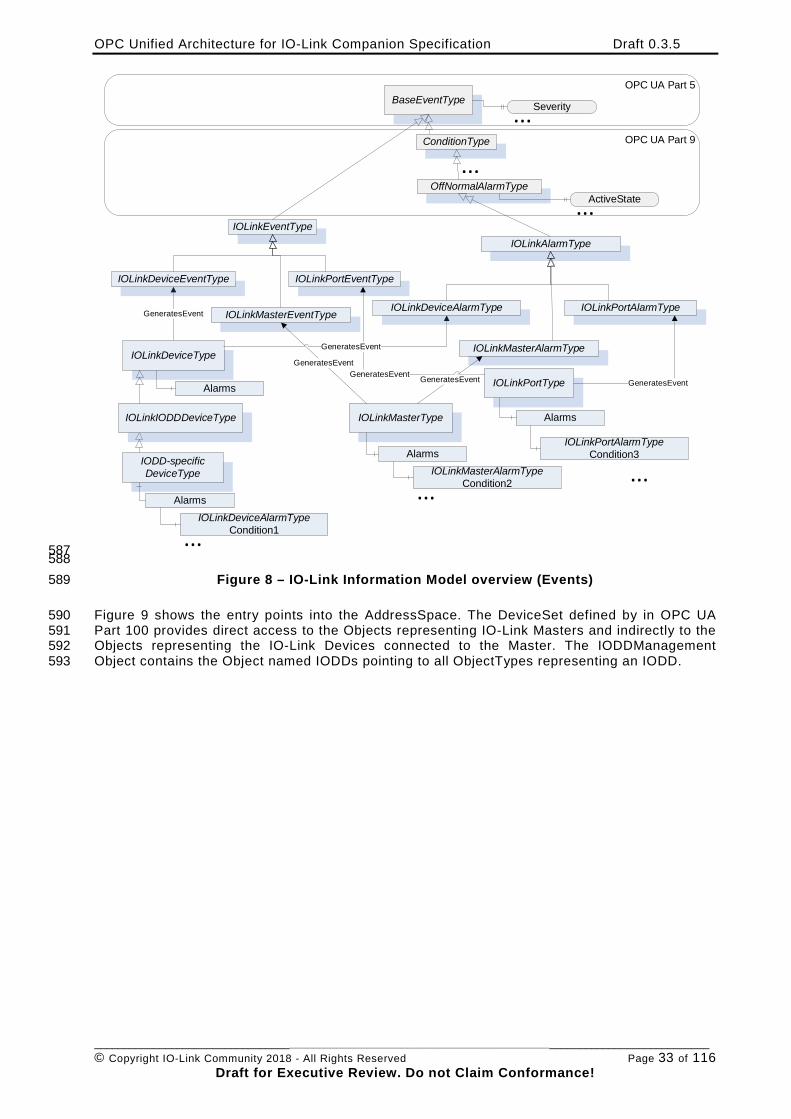
OPC Unified Architecture for IO-Link Companion Specification Draft 0.3.5
________________________________________________________________________________________________________ © Copyright IO-Link Community 2018 - All Rights Reserved Page 33 of 116
Draft for Executive Review. Do not Claim Conformance!
BaseEventType
IOLinkDeviceType
IOLinkEventType
IOLinkMasterType
Alarms
OPC UA Part 5
OPC UA Part 9
Severity...
GeneratesEvent
IOLinkDeviceEventType
IOLinkMasterEventType
IOLinkPortEventType
GeneratesEvent
IOLinkPortTypeGeneratesEvent
OffNormalAlarmTypeActiveState...
Alarms
Alarms
IOLinkAlarmType
GeneratesEvent
IOLinkDeviceAlarmType
IOLinkMasterAlarmType
IOLinkPortAlarmType
GeneratesEvent GeneratesEvent
IODD-specific DeviceType
AlarmsIOLinkDeviceAlarmType
Condition1...
IOLinkMasterAlarmTypeCondition2...
IOLinkPortAlarmTypeCondition3
...
ConditionType
...
IOLinkIODDDeviceType
587 588
Figure 8 – IO-Link Information Model overview (Events) 589
Figure 9 shows the entry points into the AddressSpace. The DeviceSet defined by in OPC UA 590 Part 100 provides direct access to the Objects representing IO-Link Masters and indirectly to the 591 Objects representing the IO-Link Devices connected to the Master. The IODDManagement 592 Object contains the Object named IODDs pointing to all ObjectTypes representing an IODD. 593

OPC Unified Architecture for IO-Link Companion Specification Draft 0.3.5
________________________________________________________________________________________________________ © Copyright IO-Link Community 2018 - All Rights Reserved Page 34 of 116
Draft for Executive Review. Do not Claim Conformance!
BaseObjectType TopologyElementType
DeviceType
IOLinkDeviceType
IODD specific Type A
IODD specific Type BIOLinkMasterType
FolderTypeRoot
OPC UA Part 5 OPC UA Part 100
FolderTypeObjects
ServerTypeServer
FolderTypeIODDManagement
FolderTypeObjectTypes
BaseObjectTypeDeviceSet
Organizes
Organizes
Organizes
Organizes
Organizes
Organizes
FolderTypeIODDs
Organizes
Organizes
IOLinkMasterTypeSampleMaster
IODD specific Type ASampleDevice1
IOLinkPortTypePort1
IOLinkIODDDeviceType
594 Figure 9 – AddressSpace entry points 595
6.3 Mapping IODD information to OPC UA ObjectTypes 596
This section gives a rough overview on how IODD information is mapped to an OPC UA 597 ObjectType. The formal definition is given in section 7.3. 598
An IODD consists of an IODevice containing meta data like DocumentInfo and ProfileHeader 599 describing an IO-Link Device. In addition, it contains information about data types 600 (DatatypeCollection), variables accessed acyclic (VariableCollection), process data 601 (ProcessDataCollection), errors (ErrorTypeCollection), events (EventCollection) and menus to 602 group information in user interfaces (UserInterface). 603
The user interface information consists of entry points for three different user roles (Observer, 604 Maintenance, and Specialist), each one containing an identification menu and optionally 605 parameter, observation, and diagnostics menus. Those menus can reference other menus or 606 variables. Optionally, the user interface information also provides information how to display the 607 process data directly (ProcessDataRefCollection). 608
The three entry points for the user roles are mapped to OPC UA FunctionalGroups. Each menu 609 that is referenced directly or indirectly as part of such an entry point is also mapped as 610 FunctionalGroup, referenced from its parent FunctionalGroup. 611
In Figure 10, an example of such a mapping is given. On the left hand, parts of an IODD are 612 shown. On the right, the representation as ObjectType in OPC UA is shown. The IODevice is 613 mapped to an ObjectType. The UserInterface information is mapped mainly to Objects of 614 FunctionalGroupType. The Observer Object is directly connected to the ObjectType, its submenu 615 Diagnostics is referenced by the Observer Object. The Diagnostics menu contains two 616 conditional menus in the IODD, which are both mapped as optional Objects under the 617 Diagnostics Object. The M_OR_Diagnosis_1132 menu references two Variables. This is mapped 618 by referencing the corresponding variables of the ParameterSet. Some details of the mapping 619 like handling conditions or additional information for Variables like EngineeringUnits are not 620 shown in the figure and defined in section 7.3. 621
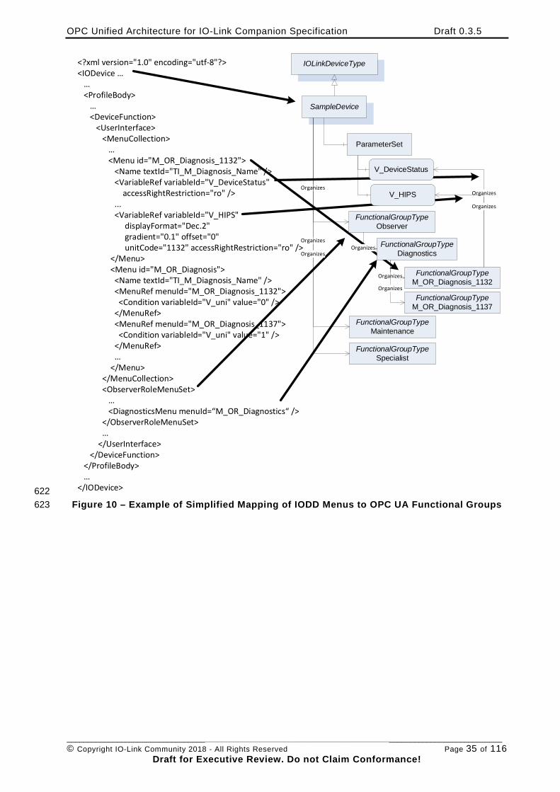
OPC Unified Architecture for IO-Link Companion Specification Draft 0.3.5
________________________________________________________________________________________________________ © Copyright IO-Link Community 2018 - All Rights Reserved Page 35 of 116
Draft for Executive Review. Do not Claim Conformance!
<?xml version="1.0" encoding="utf-8"?><IODevice … … <ProfileBody> … <DeviceFunction> <UserInterface> <MenuCollection> … <Menu id="M_OR_Diagnosis_1132"> <Name textId="TI_M_Diagnosis_Name" /> <VariableRef variableId="V_DeviceStatus" accessRightRestriction="ro" /> ... <VariableRef variableId="V_HIPS" displayFormat="Dec.2" gradient="0.1" offset="0" unitCode="1132" accessRightRestriction="ro" /> </Menu> <Menu id="M_OR_Diagnosis"> <Name textId="TI_M_Diagnosis_Name" /> <MenuRef menuId="M_OR_Diagnosis_1132"> <Condition variableId="V_uni" value="0" /> </MenuRef> <MenuRef menuId="M_OR_Diagnosis_1137"> <Condition variableId="V_uni" value="1" /> </MenuRef> … </Menu> </MenuCollection> <ObserverRoleMenuSet> … <DiagnosticsMenu menuId=“M_OR_Diagnostics“ /> </ObserverRoleMenuSet> … </UserInterface> </DeviceFunction> </ProfileBody> …</IODevice>
IOLinkDeviceType
SampleDevice
ParameterSet
FunctionalGroupTypeObserver
FunctionalGroupTypeMaintenance
FunctionalGroupTypeSpecialist
FunctionalGroupTypeM_OR_Diagnosis_1132
FunctionalGroupTypeM_OR_Diagnosis_1137
V_DeviceStatus
Organizes
V_HIPS
Organizes
Organizes
Organizes
Organizes
Organizes
OrganizesFunctionalGroupType
DiagnosticsOrganizes
622 Figure 10 – Example of Simplified Mapping of IODD Menus to OPC UA Functional Groups 623
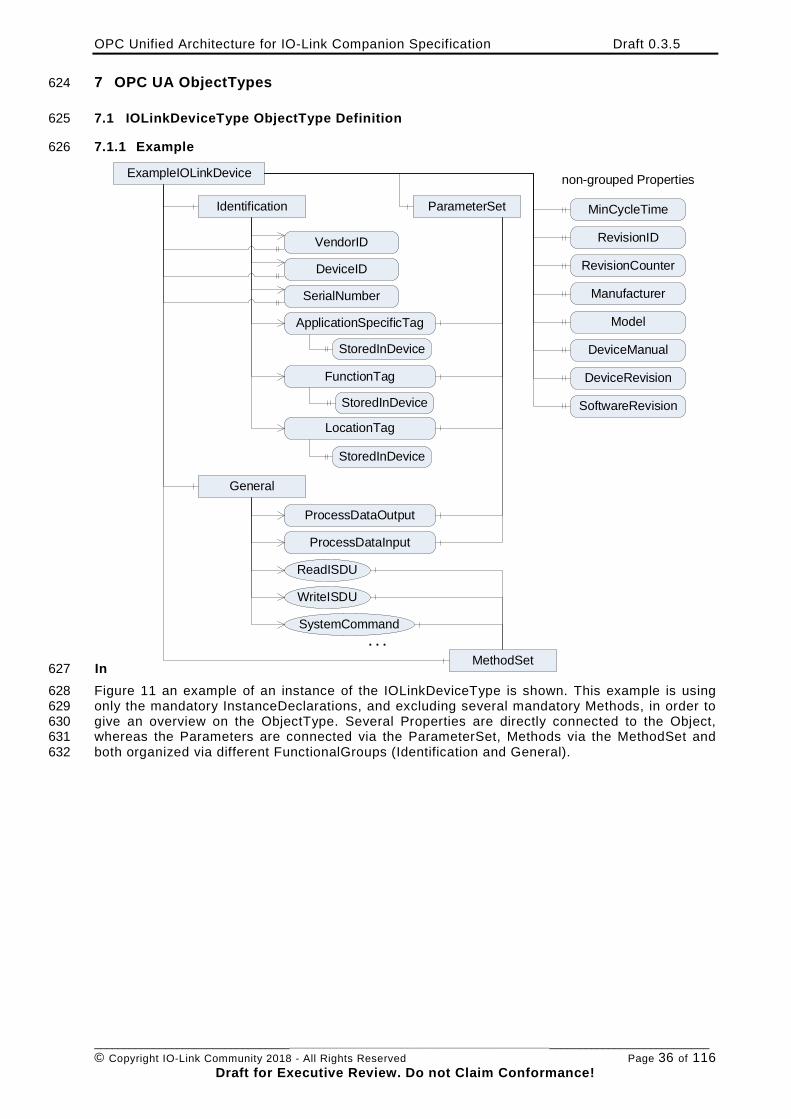
OPC Unified Architecture for IO-Link Companion Specification Draft 0.3.5
________________________________________________________________________________________________________ © Copyright IO-Link Community 2018 - All Rights Reserved Page 36 of 116
Draft for Executive Review. Do not Claim Conformance!
7 OPC UA ObjectTypes 624
7.1 IOLinkDeviceType ObjectType Definition 625
7.1.1 Example 626
In
ExampleIOLinkDevice
MinCycleTimeIdentification
VendorID
DeviceID
SerialNumber
ApplicationSpecificTag
FunctionTag
LocationTag
non-grouped Properties
RevisionID
RevisionCounter
Manufacturer
Model
DeviceManual
SoftwareRevision
DeviceRevision
General
ProcessDataOutput
ProcessDataInput
ReadISDU
WriteISDU
SystemCommand
ParameterSet
MethodSet. . .
StoredInDevice
StoredInDevice
StoredInDevice
627 Figure 11 an example of an instance of the IOLinkDeviceType is shown. This example is using 628 only the mandatory InstanceDeclarations, and excluding several mandatory Methods, in order to 629 give an overview on the ObjectType. Several Properties are directly connected to the Object, 630 whereas the Parameters are connected via the ParameterSet, Methods via the MethodSet and 631 both organized via different FunctionalGroups (Identification and General). 632
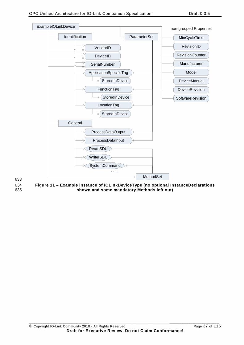
OPC Unified Architecture for IO-Link Companion Specification Draft 0.3.5
________________________________________________________________________________________________________ © Copyright IO-Link Community 2018 - All Rights Reserved Page 37 of 116
Draft for Executive Review. Do not Claim Conformance!
ExampleIOLinkDevice
MinCycleTimeIdentification
VendorID
DeviceID
SerialNumber
ApplicationSpecificTag
FunctionTag
LocationTag
non-grouped Properties
RevisionID
RevisionCounter
Manufacturer
Model
DeviceManual
SoftwareRevision
DeviceRevision
General
ProcessDataOutput
ProcessDataInput
ReadISDU
WriteISDU
SystemCommand
ParameterSet
MethodSet. . .
StoredInDevice
StoredInDevice
StoredInDevice
633 Figure 11 – Example instance of IOLinkDeviceType (no optional InstanceDeclarations 634
shown and some mandatory Methods left out) 635
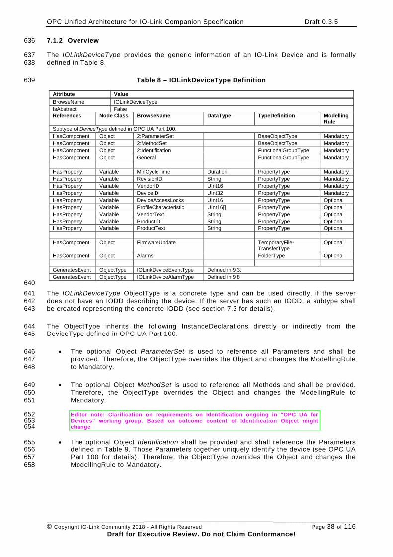
OPC Unified Architecture for IO-Link Companion Specification Draft 0.3.5
________________________________________________________________________________________________________ © Copyright IO-Link Community 2018 - All Rights Reserved Page 38 of 116
Draft for Executive Review. Do not Claim Conformance!
7.1.2 Overview 636
The IOLinkDeviceType provides the generic information of an IO-Link Device and is formally 637 defined in Table 8. 638
Table 8 – IOLinkDeviceType Definition 639
Attribute Value BrowseName IOLinkDeviceType IsAbstract False References Node Class BrowseName DataType TypeDefinition Modelling
Rule Subtype of DeviceType defined in OPC UA Part 100. HasComponent Object 2:ParameterSet BaseObjectType Mandatory HasComponent Object 2:MethodSet BaseObjectType Mandatory HasComponent Object 2:Identification FunctionalGroupType Mandatory HasComponent Object General FunctionalGroupType Mandatory HasProperty Variable MinCycleTime Duration PropertyType Mandatory HasProperty Variable RevisionID String PropertyType Mandatory HasProperty Variable VendorID UInt16 PropertyType Mandatory HasProperty Variable DeviceID UInt32 PropertyType Mandatory HasProperty Variable DeviceAccessLocks UInt16 PropertyType Optional HasProperty Variable ProfileCharacteristic UInt16[] PropertyType Optional HasProperty Variable VendorText String PropertyType Optional HasProperty Variable ProductID String PropertyType Optional HasProperty Variable ProductText String PropertyType Optional HasComponent Object FirmwareUpdate TemporaryFile-
TransferType Optional
HasComponent Object Alarms FolderType Optional GeneratesEvent ObjectType IOLinkDeviceEventType Defined in 9.3. GeneratesEvent ObjectType IOLinkDeviceAlarmType Defined in 9.8
640 The IOLinkDeviceType ObjectType is a concrete type and can be used directly, if the server 641 does not have an IODD describing the device. If the server has such an IODD, a subtype shall 642 be created representing the concrete IODD (see section 7.3 for details). 643
The ObjectType inherits the following InstanceDeclarations directly or indirectly from the 644 DeviceType defined in OPC UA Part 100. 645
• The optional Object ParameterSet is used to reference all Parameters and shall be 646 provided. Therefore, the ObjectType overrides the Object and changes the ModellingRule 647 to Mandatory. 648
• The optional Object MethodSet is used to reference all Methods and shall be provided. 649 Therefore, the ObjectType overrides the Object and changes the ModellingRule to 650 Mandatory. 651
Editor note: Clarification on requirements on Identification ongoing in “OPC UA for 652 Devices” working group. Based on outcome content of Identification Object might 653 change 654
• The optional Object Identification shall be provided and shall reference the Parameters 655 defined in Table 9. Those Parameters together uniquely identify the device (see OPC UA 656 Part 100 for details). Therefore, the ObjectType overrides the Object and changes the 657 ModellingRule to Mandatory. 658
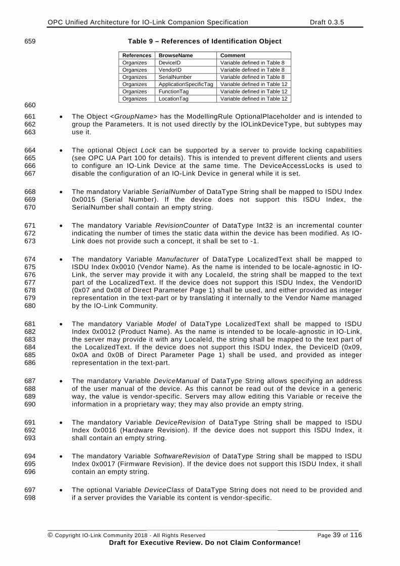
OPC Unified Architecture for IO-Link Companion Specification Draft 0.3.5
________________________________________________________________________________________________________ © Copyright IO-Link Community 2018 - All Rights Reserved Page 39 of 116
Draft for Executive Review. Do not Claim Conformance!
Table 9 – References of Identification Object 659
References BrowseName Comment Organizes DeviceID Variable defined in Table 8 Organizes VendorID Variable defined in Table 8 Organizes SerialNumber Variable defined in Table 8 Organizes ApplicationSpecificTag Variable defined in Table 12 Organizes FunctionTag Variable defined in Table 12 Organizes LocationTag Variable defined in Table 12
660 • The Object <GroupName> has the ModellingRule OptionalPlaceholder and is intended to 661
group the Parameters. It is not used directly by the IOLinkDeviceType, but subtypes may 662 use it. 663
• The optional Object Lock can be supported by a server to provide locking capabilities 664 (see OPC UA Part 100 for details). This is intended to prevent different clients and users 665 to configure an IO-Link Device at the same time. The DeviceAccessLocks is used to 666 disable the configuration of an IO-Link Device in general while it is set. 667
• The mandatory Variable SerialNumber of DataType String shall be mapped to ISDU Index 668 0x0015 (Serial Number). If the device does not support this ISDU Index, the 669 SerialNumber shall contain an empty string. 670
• The mandatory Variable RevisionCounter of DataType Int32 is an incremental counter 671 indicating the number of times the static data within the device has been modified. As IO-672 Link does not provide such a concept, it shall be set to -1. 673
• The mandatory Variable Manufacturer of DataType LocalizedText shall be mapped to 674 ISDU Index 0x0010 (Vendor Name). As the name is intended to be locale-agnostic in IO-675 Link, the server may provide it with any LocaleId, the string shall be mapped to the text 676 part of the LocalizedText. If the device does not support this ISDU Index, the VendorID 677 (0x07 and 0x08 of Direct Parameter Page 1) shall be used, and either provided as integer 678 representation in the text-part or by translating it internally to the Vendor Name managed 679 by the IO-Link Community. 680
• The mandatory Variable Model of DataType LocalizedText shall be mapped to ISDU 681 Index 0x0012 (Product Name). As the name is intended to be locale-agnostic in IO-Link, 682 the server may provide it with any LocaleId, the string shall be mapped to the text part of 683 the LocalizedText. If the device does not support this ISDU Index, the DeviceID (0x09, 684 0x0A and 0x0B of Direct Parameter Page 1) shall be used, and provided as integer 685 representation in the text-part. 686
• The mandatory Variable DeviceManual of DataType String allows specifying an address 687 of the user manual of the device. As this cannot be read out of the device in a generic 688 way, the value is vendor-specific. Servers may allow editing this Variable or receive the 689 information in a proprietary way; they may also provide an empty string. 690
• The mandatory Variable DeviceRevision of DataType String shall be mapped to ISDU 691 Index 0x0016 (Hardware Revision). If the device does not support this ISDU Index, it 692 shall contain an empty string. 693
• The mandatory Variable SoftwareRevision of DataType String shall be mapped to ISDU 694 Index 0x0017 (Firmware Revision). If the device does not support this ISDU Index, it shall 695 contain an empty string. 696
• The optional Variable DeviceClass of DataType String does not need to be provided and 697 if a server provides the Variable its content is vendor-specific. 698
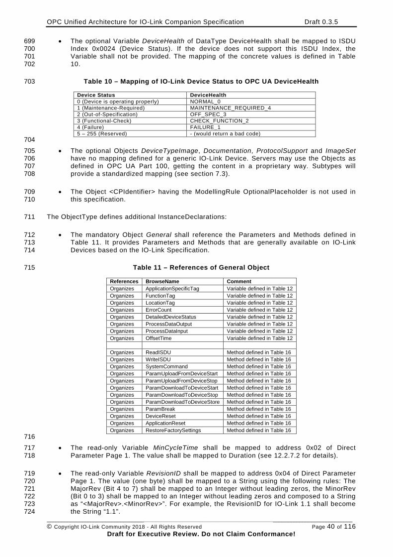
OPC Unified Architecture for IO-Link Companion Specification Draft 0.3.5
________________________________________________________________________________________________________ © Copyright IO-Link Community 2018 - All Rights Reserved Page 40 of 116
Draft for Executive Review. Do not Claim Conformance!
• The optional Variable DeviceHealth of DataType DeviceHealth shall be mapped to ISDU 699 Index 0x0024 (Device Status). If the device does not support this ISDU Index, the 700 Variable shall not be provided. The mapping of the concrete values is defined in Table 701 10. 702
Table 10 – Mapping of IO-Link Device Status to OPC UA DeviceHealth 703
Device Status DeviceHealth 0 (Device is operating properly) NORMAL_0 1 (Maintenance-Required) MAINTENANCE_REQUIRED_4 2 (Out-of-Specification) OFF_SPEC_3 3 (Functional-Check) CHECK_FUNCTION_2 4 (Failure) FAILURE_1 5 – 255 (Reserved) - (would return a bad code)
704 • The optional Objects DeviceTypeImage, Documentation, ProtocolSupport and ImageSet 705
have no mapping defined for a generic IO-Link Device. Servers may use the Objects as 706 defined in OPC UA Part 100, getting the content in a proprietary way. Subtypes will 707 provide a standardized mapping (see section 7.3). 708
• The Object <CPIdentifier> having the ModellingRule OptionalPlaceholder is not used in 709 this specification. 710
The ObjectType defines additional InstanceDeclarations: 711
• The mandatory Object General shall reference the Parameters and Methods defined in 712 Table 11. It provides Parameters and Methods that are generally available on IO-Link 713 Devices based on the IO-Link Specification. 714
Table 11 – References of General Object 715
References BrowseName Comment Organizes ApplicationSpecificTag Variable defined in Table 12 Organizes FunctionTag Variable defined in Table 12 Organizes LocationTag Variable defined in Table 12 Organizes ErrorCount Variable defined in Table 12 Organizes DetailedDeviceStatus Variable defined in Table 12 Organizes ProcessDataOutput Variable defined in Table 12 Organizes ProcessDataInput Variable defined in Table 12 Organizes OffsetTime Variable defined in Table 12 Organizes ReadISDU Method defined in Table 16 Organizes WriteISDU Method defined in Table 16 Organizes SystemCommand Method defined in Table 16 Organizes ParamUploadFromDeviceStart Method defined in Table 16 Organizes ParamUploadFromDeviceStop Method defined in Table 16 Organizes ParamDownloadToDeviceStart Method defined in Table 16 Organizes ParamDownloadToDeviceStop Method defined in Table 16 Organizes ParamDownloadToDeviceStore Method defined in Table 16 Organizes ParamBreak Method defined in Table 16 Organizes DeviceReset Method defined in Table 16 Organizes ApplicationReset Method defined in Table 16 Organizes RestoreFactorySettings Method defined in Table 16
716 • The read-only Variable MinCycleTime shall be mapped to address 0x02 of Direct 717
Parameter Page 1. The value shall be mapped to Duration (see 12.2.7.2 for details). 718
• The read-only Variable RevisionID shall be mapped to address 0x04 of Direct Parameter 719 Page 1. The value (one byte) shall be mapped to a String using the following rules: The 720 MajorRev (Bit 4 to 7) shall be mapped to an Integer without leading zeros, the MinorRev 721 (Bit 0 to 3) shall be mapped to an Integer without leading zeros and composed to a String 722 as “<MajorRev>.<MinorRev>”. For example, the RevisionID for IO-Link 1.1 shall become 723 the String “1.1”. 724
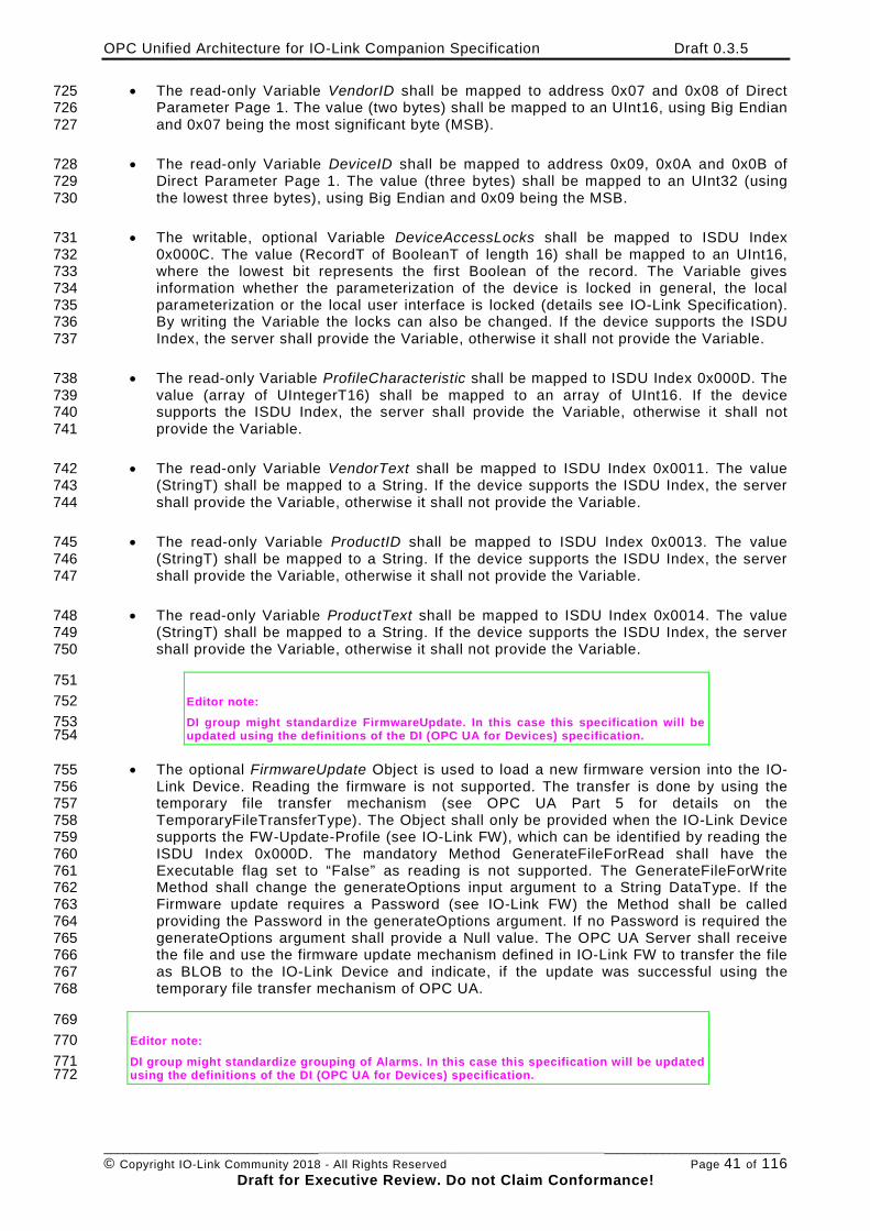
OPC Unified Architecture for IO-Link Companion Specification Draft 0.3.5
________________________________________________________________________________________________________ © Copyright IO-Link Community 2018 - All Rights Reserved Page 41 of 116
Draft for Executive Review. Do not Claim Conformance!
• The read-only Variable VendorID shall be mapped to address 0x07 and 0x08 of Direct 725 Parameter Page 1. The value (two bytes) shall be mapped to an UInt16, using Big Endian 726 and 0x07 being the most significant byte (MSB). 727
• The read-only Variable DeviceID shall be mapped to address 0x09, 0x0A and 0x0B of 728 Direct Parameter Page 1. The value (three bytes) shall be mapped to an UInt32 (using 729 the lowest three bytes), using Big Endian and 0x09 being the MSB. 730
• The writable, optional Variable DeviceAccessLocks shall be mapped to ISDU Index 731 0x000C. The value (RecordT of BooleanT of length 16) shall be mapped to an UInt16, 732 where the lowest bit represents the first Boolean of the record. The Variable gives 733 information whether the parameterization of the device is locked in general, the local 734 parameterization or the local user interface is locked (details see IO-Link Specification). 735 By writing the Variable the locks can also be changed. If the device supports the ISDU 736 Index, the server shall provide the Variable, otherwise it shall not provide the Variable. 737
• The read-only Variable ProfileCharacteristic shall be mapped to ISDU Index 0x000D. The 738 value (array of UIntegerT16) shall be mapped to an array of UInt16. If the device 739 supports the ISDU Index, the server shall provide the Variable, otherwise it shall not 740 provide the Variable. 741
• The read-only Variable VendorText shall be mapped to ISDU Index 0x0011. The value 742 (StringT) shall be mapped to a String. If the device supports the ISDU Index, the server 743 shall provide the Variable, otherwise it shall not provide the Variable. 744
• The read-only Variable ProductID shall be mapped to ISDU Index 0x0013. The value 745 (StringT) shall be mapped to a String. If the device supports the ISDU Index, the server 746 shall provide the Variable, otherwise it shall not provide the Variable. 747
• The read-only Variable ProductText shall be mapped to ISDU Index 0x0014. The value 748 (StringT) shall be mapped to a String. If the device supports the ISDU Index, the server 749 shall provide the Variable, otherwise it shall not provide the Variable. 750
751 Editor note: 752 DI group might standardize FirmwareUpdate. In this case this specification will be 753 updated using the definitions of the DI (OPC UA for Devices) specification. 754
• The optional FirmwareUpdate Object is used to load a new firmware version into the IO-755 Link Device. Reading the firmware is not supported. The transfer is done by using the 756 temporary file transfer mechanism (see OPC UA Part 5 for details on the 757 TemporaryFileTransferType). The Object shall only be provided when the IO-Link Device 758 supports the FW-Update-Profile (see IO-Link FW), which can be identified by reading the 759 ISDU Index 0x000D. The mandatory Method GenerateFileForRead shall have the 760 Executable flag set to “False” as reading is not supported. The GenerateFileForWrite 761 Method shall change the generateOptions input argument to a String DataType. If the 762 Firmware update requires a Password (see IO-Link FW) the Method shall be called 763 providing the Password in the generateOptions argument. If no Password is required the 764 generateOptions argument shall provide a Null value. The OPC UA Server shall receive 765 the file and use the firmware update mechanism defined in IO-Link FW to transfer the file 766 as BLOB to the IO-Link Device and indicate, if the update was successful using the 767 temporary file transfer mechanism of OPC UA. 768
769 Editor note: 770 DI group might standardize grouping of Alarms. In this case this specification will be updated 771 using the definitions of the DI (OPC UA for Devices) specification. 772
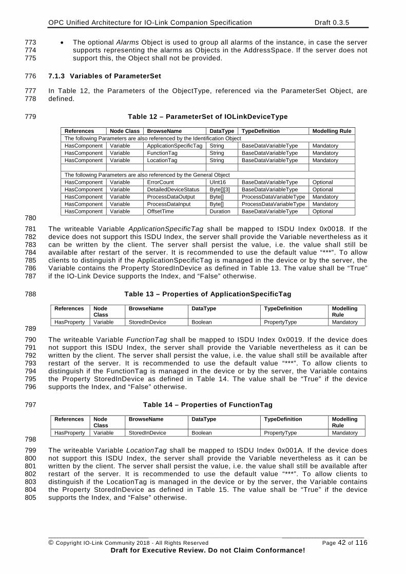
OPC Unified Architecture for IO-Link Companion Specification Draft 0.3.5
________________________________________________________________________________________________________ © Copyright IO-Link Community 2018 - All Rights Reserved Page 42 of 116
Draft for Executive Review. Do not Claim Conformance!
• The optional Alarms Object is used to group all alarms of the instance, in case the server 773 supports representing the alarms as Objects in the AddressSpace. If the server does not 774 support this, the Object shall not be provided. 775
7.1.3 Variables of ParameterSet 776
In Table 12, the Parameters of the ObjectType, referenced via the ParameterSet Object, are 777 defined. 778
Table 12 – ParameterSet of IOLinkDeviceType 779
References Node Class BrowseName DataType TypeDefinition Modelling Rule The following Parameters are also referenced by the Identification Object HasComponent Variable ApplicationSpecificTag String BaseDataVariableType Mandatory HasComponent Variable FunctionTag String BaseDataVariableType Mandatory HasComponent Variable LocationTag String BaseDataVariableType Mandatory The following Parameters are also referenced by the General Object HasComponent Variable ErrorCount UInt16 BaseDataVariableType Optional HasComponent Variable DetailedDeviceStatus Byte[][3] BaseDataVariableType Optional HasComponent Variable ProcessDataOutput Byte[] ProcessDataVariableType Mandatory HasComponent Variable ProcessDataInput Byte[] ProcessDataVariableType Mandatory HasComponent Variable OffsetTime Duration BaseDataVariableType Optional
780 The writeable Variable ApplicationSpecificTag shall be mapped to ISDU Index 0x0018. If the 781 device does not support this ISDU Index, the server shall provide the Variable nevertheless as it 782 can be written by the client. The server shall persist the value, i.e. the value shall still be 783 available after restart of the server. It is recommended to use the default value “***”. To allow 784 clients to distinguish if the ApplicationSpecificTag is managed in the device or by the server, the 785 Variable contains the Property StoredInDevice as defined in Table 13. The value shall be “True” 786 if the IO-Link Device supports the Index, and “False” otherwise. 787
Table 13 – Properties of ApplicationSpecificTag 788
References Node Class
BrowseName DataType TypeDefinition Modelling Rule
HasProperty Variable StoredInDevice Boolean PropertyType Mandatory 789 The writeable Variable FunctionTag shall be mapped to ISDU Index 0x0019. If the device does 790 not support this ISDU Index, the server shall provide the Variable nevertheless as it can be 791 written by the client. The server shall persist the value, i.e. the value shall still be available after 792 restart of the server. It is recommended to use the default value “***”. To allow clients to 793 distinguish if the FunctionTag is managed in the device or by the server, the Variable contains 794 the Property StoredInDevice as defined in Table 14. The value shall be “True” if the device 795 supports the Index, and “False” otherwise. 796
Table 14 – Properties of FunctionTag 797
References Node Class
BrowseName DataType TypeDefinition Modelling Rule
HasProperty Variable StoredInDevice Boolean PropertyType Mandatory 798 The writeable Variable LocationTag shall be mapped to ISDU Index 0x001A. If the device does 799 not support this ISDU Index, the server shall provide the Variable nevertheless as it can be 800 written by the client. The server shall persist the value, i.e. the value shall still be available after 801 restart of the server. It is recommended to use the default value “***”. To allow clients to 802 distinguish if the LocationTag is managed in the device or by the server, the Variable contains 803 the Property StoredInDevice as defined in Table 15. The value shall be “True” if the device 804 supports the Index, and “False” otherwise. 805
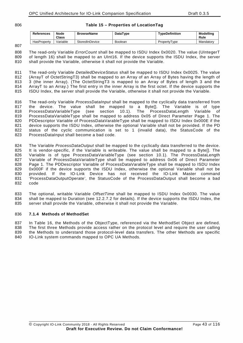
OPC Unified Architecture for IO-Link Companion Specification Draft 0.3.5
________________________________________________________________________________________________________ © Copyright IO-Link Community 2018 - All Rights Reserved Page 43 of 116
Draft for Executive Review. Do not Claim Conformance!
Table 15 – Properties of LocationTag 806
References Node Class
BrowseName DataType TypeDefinition Modelling Rule
HasProperty Variable StoredInDevice Boolean PropertyType Mandatory 807 The read-only Variable ErrorCount shall be mapped to ISDU Index 0x0020. The value (UIntegerT 808 of length 16) shall be mapped to an UInt16. If the device supports the ISDU Index, the server 809 shall provide the Variable, otherwise it shall not provide the Variable. 810
The read-only Variable DetailedDeviceStatus shall be mapped to ISDU Index 0x0025. The value 811 (ArrayT of OctetStringT3) shall be mapped to an Array of an Array of Bytes having the length of 812 3 (the inner Array). (The OctetStringT3 is mapped to an Array of Bytes of length 3 and the 813 ArrayT to an Array.) The first entry in the inner Array is the first octet. If the device supports the 814 ISDU Index, the server shall provide the Variable, otherwise it shall not provide the Variable. 815
The read-only Variable ProcessDataInput shall be mapped to the cyclically data transferred from 816 the device. The value shall be mapped to a Byte[]. The Variable is of type 817 ProcessDataVariableType (see section 10.1). The ProcessDataLength Variable of 818 ProcessDataVariableType shall be mapped to address 0x05 of Direct Parameter Page 1. The 819 PDDescriptor Variable of ProcessDataVarableType shall be mapped to ISDU Index 0x000E if the 820 device supports the ISDU Index, otherwise the optional Variable shall not be provided. If the PD 821 status of the cyclic communication is set to 1 (invalid data), the StatusCode of the 822 ProcessDataInput shall become a bad code. 823
The Variable ProcessDataOutput shall be mapped to the cyclically data transferred to the device. 824 It is vendor-specific, if the Variable is writeable. The value shall be mapped to a Byte[]. The 825 Variable is of type ProcessDataVariableType (see section 10.1). The ProcessDataLength 826 Variable of ProcessDataVariableType shall be mapped to address 0x06 of Direct Parameter 827 Page 1. The PDDescriptor Variable of ProcessDataVarableType shall be mapped to ISDU Index 828 0x000F if the device supports the ISDU Index, otherwise the optional Variable shall not be 829 provided. If the IO-Link Device has not received the IO-Link Master command 830 ‘ProcessDataOutputOperate’, the StatusCode of the ProcessDataOutput shall become a bad 831 code 832
The optional, writable Variable OffsetTime shall be mapped to ISDU Index 0x0030. The value 833 shall be mapped to Duration (see 12.2.7.2 for details). If the device supports the ISDU Index, the 834 server shall provide the Variable, otherwise it shall not provide the Variable. 835
7.1.4 Methods of MethodSet 836
In Table 16, the Methods of the ObjectType, referenced via the MethodSet Object are defined. 837 The first three Methods provide access rather on the protocol level and require the user calling 838 the Methods to understand those protocol-level data transfers. The other Methods are specific 839 IO-Link system commands mapped to OPC UA Methods. 840
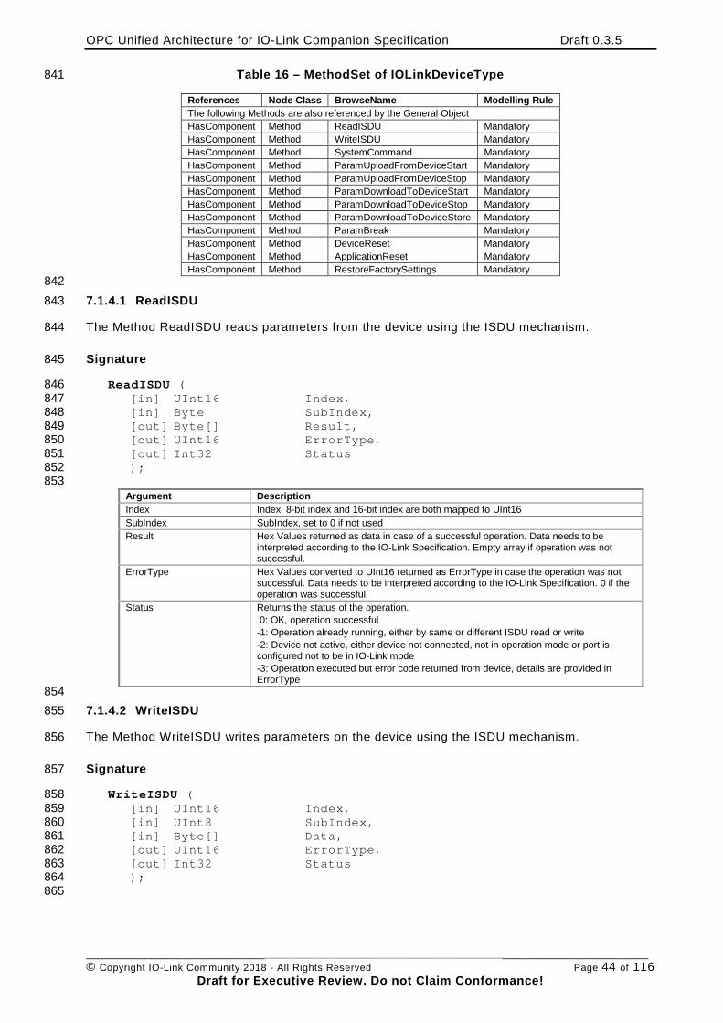
OPC Unified Architecture for IO-Link Companion Specification Draft 0.3.5
________________________________________________________________________________________________________ © Copyright IO-Link Community 2018 - All Rights Reserved Page 44 of 116
Draft for Executive Review. Do not Claim Conformance!
Table 16 – MethodSet of IOLinkDeviceType 841
References Node Class BrowseName Modelling Rule The following Methods are also referenced by the General Object HasComponent Method ReadISDU Mandatory HasComponent Method WriteISDU Mandatory HasComponent Method SystemCommand Mandatory HasComponent Method ParamUploadFromDeviceStart Mandatory HasComponent Method ParamUploadFromDeviceStop Mandatory HasComponent Method ParamDownloadToDeviceStart Mandatory HasComponent Method ParamDownloadToDeviceStop Mandatory HasComponent Method ParamDownloadToDeviceStore Mandatory HasComponent Method ParamBreak Mandatory HasComponent Method DeviceReset Mandatory HasComponent Method ApplicationReset Mandatory HasComponent Method RestoreFactorySettings Mandatory
842 7.1.4.1 ReadISDU 843
The Method ReadISDU reads parameters from the device using the ISDU mechanism. 844
Signature 845
ReadISDU ( 846 [in] UInt16 Index, 847 [in] Byte SubIndex, 848 [out] Byte[] Result, 849 [out] UInt16 ErrorType, 850 [out] Int32 Status 851 ); 852 853
Argument Description Index Index, 8-bit index and 16-bit index are both mapped to UInt16 SubIndex SubIndex, set to 0 if not used Result Hex Values returned as data in case of a successful operation. Data needs to be
interpreted according to the IO-Link Specification. Empty array if operation was not successful.
ErrorType Hex Values converted to UInt16 returned as ErrorType in case the operation was not successful. Data needs to be interpreted according to the IO-Link Specification. 0 if the operation was successful.
Status Returns the status of the operation. 0: OK, operation successful -1: Operation already running, either by same or different ISDU read or write -2: Device not active, either device not connected, not in operation mode or port is configured not to be in IO-Link mode -3: Operation executed but error code returned from device, details are provided in ErrorType
854 7.1.4.2 WriteISDU 855
The Method WriteISDU writes parameters on the device using the ISDU mechanism. 856
Signature 857
WriteISDU ( 858 [in] UInt16 Index, 859 [in] UInt8 SubIndex, 860 [in] Byte[] Data, 861 [out] UInt16 ErrorType, 862 [out] Int32 Status 863 ); 864 865
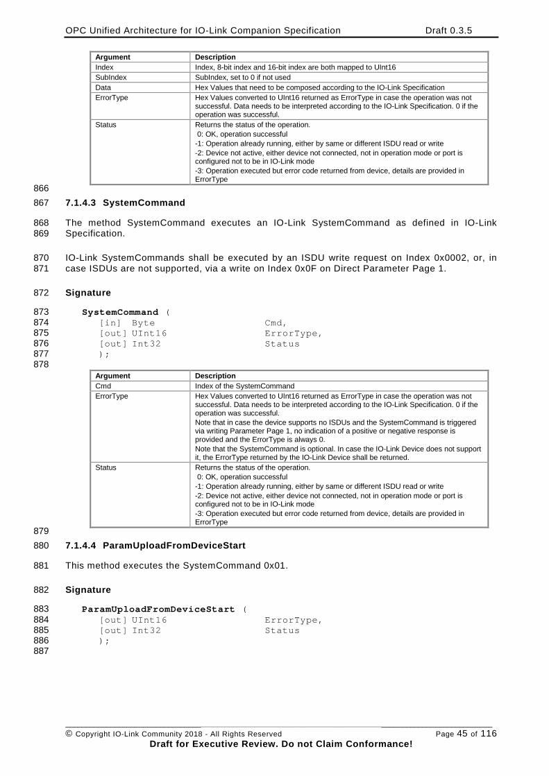
OPC Unified Architecture for IO-Link Companion Specification Draft 0.3.5
________________________________________________________________________________________________________ © Copyright IO-Link Community 2018 - All Rights Reserved Page 45 of 116
Draft for Executive Review. Do not Claim Conformance!
Argument Description Index Index, 8-bit index and 16-bit index are both mapped to UInt16 SubIndex SubIndex, set to 0 if not used Data Hex Values that need to be composed according to the IO-Link Specification ErrorType Hex Values converted to UInt16 returned as ErrorType in case the operation was not
successful. Data needs to be interpreted according to the IO-Link Specification. 0 if the operation was successful.
Status Returns the status of the operation. 0: OK, operation successful -1: Operation already running, either by same or different ISDU read or write -2: Device not active, either device not connected, not in operation mode or port is configured not to be in IO-Link mode -3: Operation executed but error code returned from device, details are provided in ErrorType
866 7.1.4.3 SystemCommand 867
The method SystemCommand executes an IO-Link SystemCommand as defined in IO-Link 868 Specification. 869
IO-Link SystemCommands shall be executed by an ISDU write request on Index 0x0002, or, in 870 case ISDUs are not supported, via a write on Index 0x0F on Direct Parameter Page 1. 871
Signature 872
SystemCommand ( 873 [in] Byte Cmd, 874 [out] UInt16 ErrorType, 875 [out] Int32 Status 876 ); 877 878
Argument Description Cmd Index of the SystemCommand ErrorType Hex Values converted to UInt16 returned as ErrorType in case the operation was not
successful. Data needs to be interpreted according to the IO-Link Specification. 0 if the operation was successful. Note that in case the device supports no ISDUs and the SystemCommand is triggered via writing Parameter Page 1, no indication of a positive or negative response is provided and the ErrorType is always 0. Note that the SystemCommand is optional. In case the IO-Link Device does not support it, the ErrorType returned by the IO-Link Device shall be returned.
Status Returns the status of the operation. 0: OK, operation successful -1: Operation already running, either by same or different ISDU read or write -2: Device not active, either device not connected, not in operation mode or port is configured not to be in IO-Link mode -3: Operation executed but error code returned from device, details are provided in ErrorType
879 7.1.4.4 ParamUploadFromDeviceStart 880
This method executes the SystemCommand 0x01. 881
Signature 882
ParamUploadFromDeviceStart ( 883 [out] UInt16 ErrorType, 884 [out] Int32 Status 885 ); 886 887
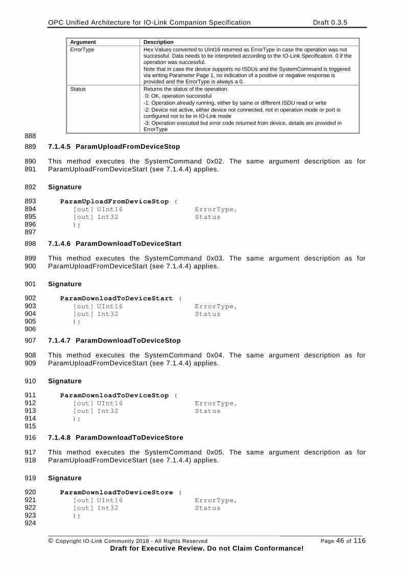
OPC Unified Architecture for IO-Link Companion Specification Draft 0.3.5
________________________________________________________________________________________________________ © Copyright IO-Link Community 2018 - All Rights Reserved Page 46 of 116
Draft for Executive Review. Do not Claim Conformance!
Argument Description ErrorType Hex Values converted to UInt16 returned as ErrorType in case the operation was not
successful. Data needs to be interpreted according to the IO-Link Specification. 0 if the operation was successful. Note that in case the device supports no ISDUs and the SystemCommand is triggered via writing Parameter Page 1, no indication of a positive or negative response is provided and the ErrorType is always a 0.
Status Returns the status of the operation. 0: OK, operation successful -1: Operation already running, either by same or different ISDU read or write -2: Device not active, either device not connected, not in operation mode or port is configured not to be in IO-Link mode -3: Operation executed but error code returned from device, details are provided in ErrorType
888 7.1.4.5 ParamUploadFromDeviceStop 889
This method executes the SystemCommand 0x02. The same argument description as for 890 ParamUploadFromDeviceStart (see 7.1.4.4) applies. 891
Signature 892
ParamUploadFromDeviceStop ( 893 [out] UInt16 ErrorType, 894 [out] Int32 Status 895 ); 896 897
7.1.4.6 ParamDownloadToDeviceStart 898
This method executes the SystemCommand 0x03. The same argument description as for 899 ParamUploadFromDeviceStart (see 7.1.4.4) applies. 900
Signature 901
ParamDownloadToDeviceStart ( 902 [out] UInt16 ErrorType, 903 [out] Int32 Status 904 ); 905 906
7.1.4.7 ParamDownloadToDeviceStop 907
This method executes the SystemCommand 0x04. The same argument description as for 908 ParamUploadFromDeviceStart (see 7.1.4.4) applies. 909
Signature 910
ParamDownloadToDeviceStop ( 911 [out] UInt16 ErrorType, 912 [out] Int32 Status 913 ); 914 915
7.1.4.8 ParamDownloadToDeviceStore 916
This method executes the SystemCommand 0x05. The same argument description as for 917 ParamUploadFromDeviceStart (see 7.1.4.4) applies. 918
Signature 919
ParamDownloadToDeviceStore ( 920 [out] UInt16 ErrorType, 921 [out] Int32 Status 922 ); 923 924
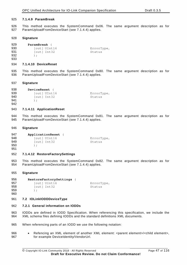
OPC Unified Architecture for IO-Link Companion Specification Draft 0.3.5
________________________________________________________________________________________________________ © Copyright IO-Link Community 2018 - All Rights Reserved Page 47 of 116
Draft for Executive Review. Do not Claim Conformance!
7.1.4.9 ParamBreak 925
This method executes the SystemCommand 0x06. The same argument description as for 926 ParamUploadFromDeviceStart (see 7.1.4.4) applies. 927
Signature 928
ParamBreak ( 929 [out] UInt16 ErrorType, 930 [out] Int32 Status 931 ); 932 933
7.1.4.10 DeviceReset 934
This method executes the SystemCommand 0x80. The same argument description as for 935 ParamUploadFromDeviceStart (see 7.1.4.4) applies. 936
Signature 937
DeviceReset ( 938 [out] UInt16 ErrorType, 939 [out] Int32 Status 940 ); 941 942
7.1.4.11 ApplicationReset 943
This method executes the SystemCommand 0x81. The same argument description as for 944 ParamUploadFromDeviceStart (see 7.1.4.4) applies. 945
Signature 946
ApplicationReset ( 947 [out] UInt16 ErrorType, 948 [out] Int32 Status 949 ); 950 951
7.1.4.12 RestoreFactorySettings 952
This method executes the SystemCommand 0x82. The same argument description as for 953 ParamUploadFromDeviceStart (see 7.1.4.4) applies. 954
Signature 955
RestoreFactorySettings ( 956 [out] UInt16 ErrorType, 957 [out] Int32 Status 958 ); 959
960 7.2 IOLinkIODDDeviceType 961
7.2.1 General information on IODDs 962
IODDs are defined in IODD Specification. When referencing this specification, we include the 963 XML schema files defining IODDs and the standard definitions XML documents. 964
When referencing parts of an IODD we use the following notation: 965
• Refencing an XML element of another XML element: <parent element>/<child element>, 966 for example DeviceIdentity/VendorUrl. 967
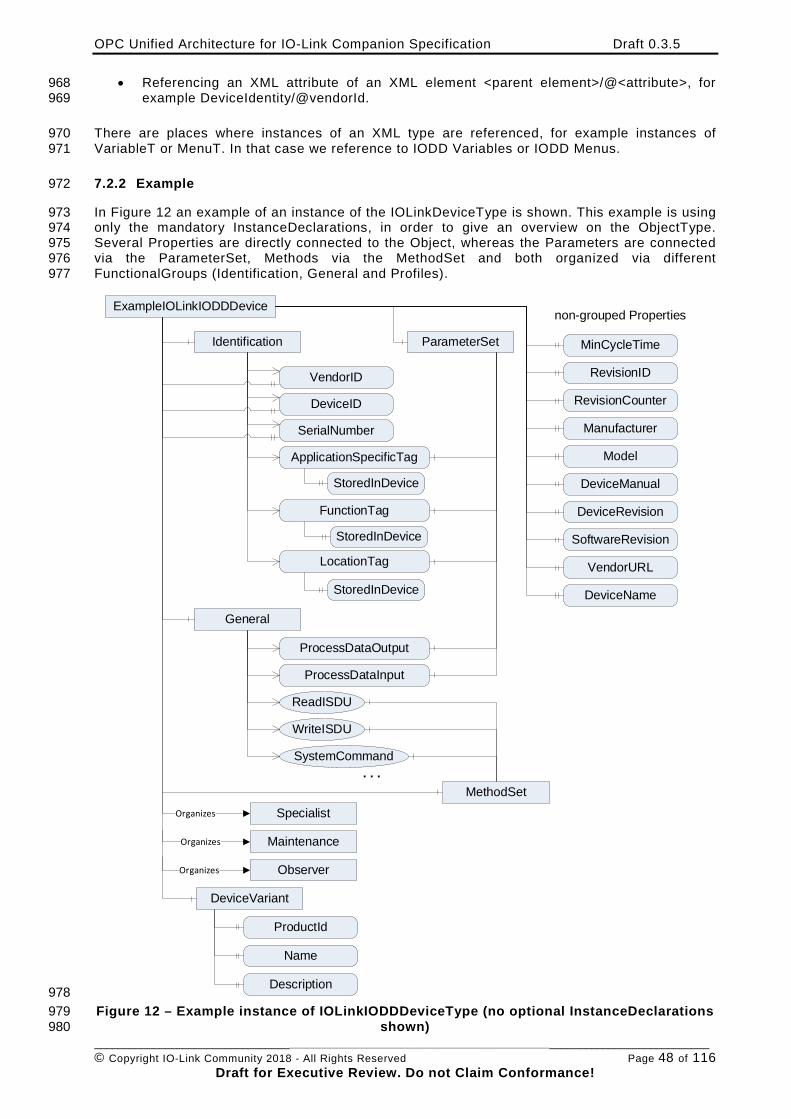
OPC Unified Architecture for IO-Link Companion Specification Draft 0.3.5
________________________________________________________________________________________________________ © Copyright IO-Link Community 2018 - All Rights Reserved Page 48 of 116
Draft for Executive Review. Do not Claim Conformance!
• Referencing an XML attribute of an XML element <parent element>/@<attribute>, for 968 example DeviceIdentity/@vendorId. 969
There are places where instances of an XML type are referenced, for example instances of 970 VariableT or MenuT. In that case we reference to IODD Variables or IODD Menus. 971
7.2.2 Example 972
In Figure 12 an example of an instance of the IOLinkDeviceType is shown. This example is using 973 only the mandatory InstanceDeclarations, in order to give an overview on the ObjectType. 974 Several Properties are directly connected to the Object, whereas the Parameters are connected 975 via the ParameterSet, Methods via the MethodSet and both organized via different 976 FunctionalGroups (Identification, General and Profiles). 977
ExampleIOLinkIODDDevice
MinCycleTimeIdentification
VendorID
DeviceID
SerialNumber
ApplicationSpecificTag
FunctionTag
LocationTag
non-grouped Properties
RevisionID
RevisionCounter
Manufacturer
Model
DeviceManual
SoftwareRevision
DeviceRevision
General
ProcessDataOutput
ProcessDataInput
ReadISDU
WriteISDU
SystemCommand
ParameterSet
MethodSet. . .
StoredInDevice
StoredInDevice
StoredInDevice
VendorURL
DeviceName
Specialist
DeviceVariant
Maintenance
Observer
Organizes
Organizes
Organizes
ProductId
Name
Description 978 Figure 12 – Example instance of IOLinkIODDDeviceType (no optional InstanceDeclarations 979
shown) 980
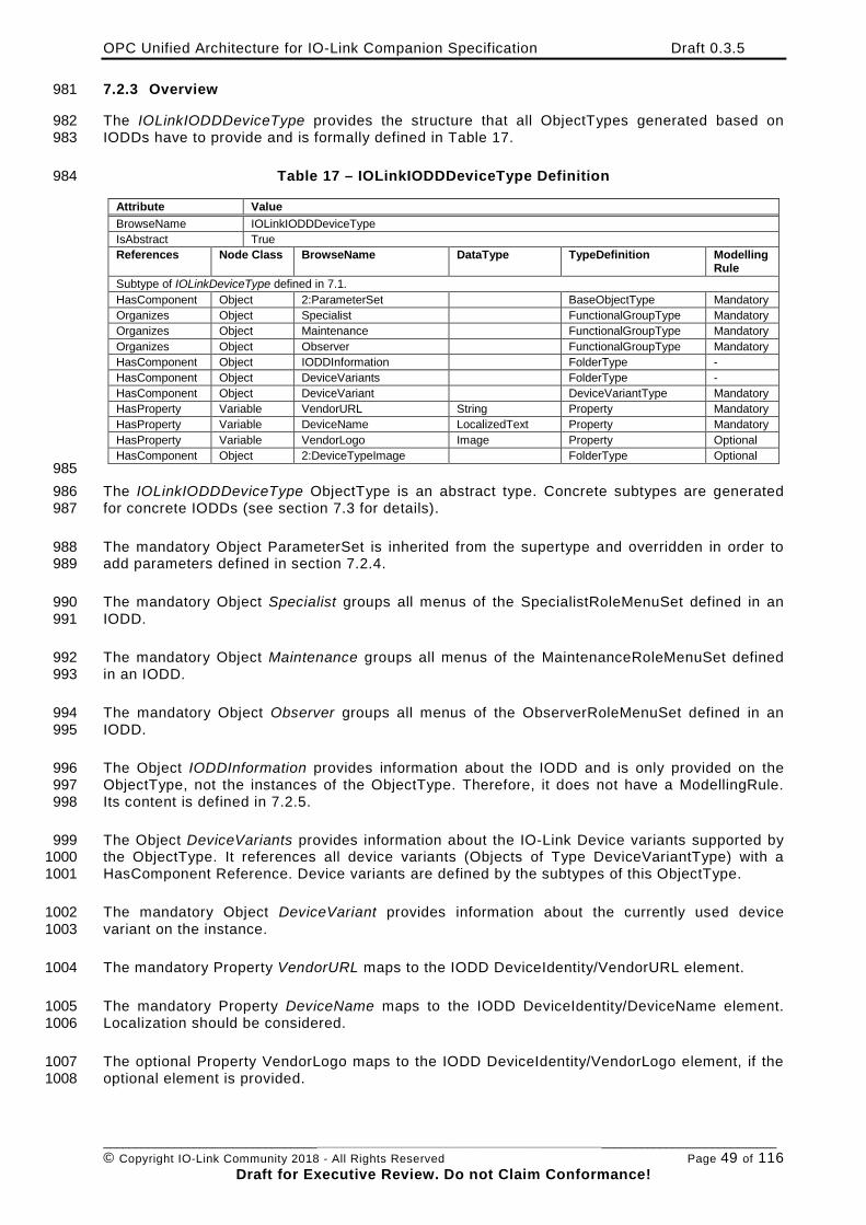
OPC Unified Architecture for IO-Link Companion Specification Draft 0.3.5
________________________________________________________________________________________________________ © Copyright IO-Link Community 2018 - All Rights Reserved Page 49 of 116
Draft for Executive Review. Do not Claim Conformance!
7.2.3 Overview 981
The IOLinkIODDDeviceType provides the structure that all ObjectTypes generated based on 982 IODDs have to provide and is formally defined in Table 17. 983
Table 17 – IOLinkIODDDeviceType Definition 984
Attribute Value BrowseName IOLinkIODDDeviceType IsAbstract True References Node Class BrowseName DataType TypeDefinition Modelling
Rule Subtype of IOLinkDeviceType defined in 7.1. HasComponent Object 2:ParameterSet BaseObjectType Mandatory Organizes Object Specialist FunctionalGroupType Mandatory Organizes Object Maintenance FunctionalGroupType Mandatory Organizes Object Observer FunctionalGroupType Mandatory HasComponent Object IODDInformation FolderType - HasComponent Object DeviceVariants FolderType - HasComponent Object DeviceVariant DeviceVariantType Mandatory HasProperty Variable VendorURL String Property Mandatory HasProperty Variable DeviceName LocalizedText Property Mandatory HasProperty Variable VendorLogo Image Property Optional HasComponent Object 2:DeviceTypeImage FolderType Optional
985 The IOLinkIODDDeviceType ObjectType is an abstract type. Concrete subtypes are generated 986 for concrete IODDs (see section 7.3 for details). 987
The mandatory Object ParameterSet is inherited from the supertype and overridden in order to 988 add parameters defined in section 7.2.4. 989
The mandatory Object Specialist groups all menus of the SpecialistRoleMenuSet defined in an 990 IODD. 991
The mandatory Object Maintenance groups all menus of the MaintenanceRoleMenuSet defined 992 in an IODD. 993
The mandatory Object Observer groups all menus of the ObserverRoleMenuSet defined in an 994 IODD. 995
The Object IODDInformation provides information about the IODD and is only provided on the 996 ObjectType, not the instances of the ObjectType. Therefore, it does not have a ModellingRule. 997 Its content is defined in 7.2.5. 998
The Object DeviceVariants provides information about the IO-Link Device variants supported by 999 the ObjectType. It references all device variants (Objects of Type DeviceVariantType) with a 1000 HasComponent Reference. Device variants are defined by the subtypes of this ObjectType. 1001
The mandatory Object DeviceVariant provides information about the currently used device 1002 variant on the instance. 1003
The mandatory Property VendorURL maps to the IODD DeviceIdentity/VendorURL element. 1004
The mandatory Property DeviceName maps to the IODD DeviceIdentity/DeviceName element. 1005 Localization should be considered. 1006
The optional Property VendorLogo maps to the IODD DeviceIdentity/VendorLogo element, if the 1007 optional element is provided. 1008
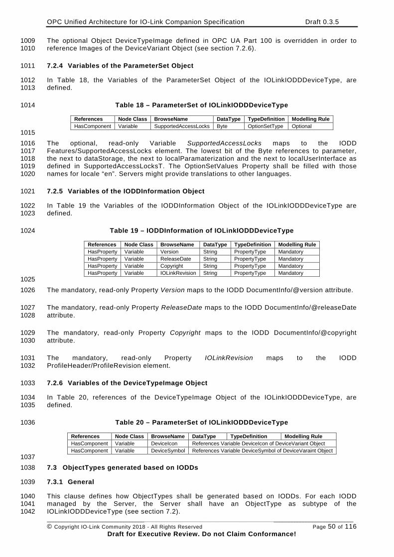
OPC Unified Architecture for IO-Link Companion Specification Draft 0.3.5
________________________________________________________________________________________________________ © Copyright IO-Link Community 2018 - All Rights Reserved Page 50 of 116
Draft for Executive Review. Do not Claim Conformance!
The optional Object DeviceTypeImage defined in OPC UA Part 100 is overridden in order to 1009 reference Images of the DeviceVariant Object (see section 7.2.6). 1010
7.2.4 Variables of the ParameterSet Object 1011
In Table 18, the Variables of the ParameterSet Object of the IOLinkIODDDeviceType, are 1012 defined. 1013
Table 18 – ParameterSet of IOLinkIODDDeviceType 1014
References Node Class BrowseName DataType TypeDefinition Modelling Rule HasComponent Variable SupportedAccessLocks Byte OptionSetType Optional
1015 The optional, read-only Variable SupportedAccessLocks maps to the IODD 1016 Features/SupportedAccessLocks element. The lowest bit of the Byte references to parameter, 1017 the next to dataStorage, the next to localParamaterization and the next to localUserInterface as 1018 defined in SupportedAccessLocksT. The OptionSetValues Property shall be filled with those 1019 names for locale “en”. Servers might provide translations to other languages. 1020
7.2.5 Variables of the IODDInformation Object 1021
In Table 19 the Variables of the IODDInformation Object of the IOLinkIODDDeviceType are 1022 defined. 1023
Table 19 – IODDInformation of IOLinkIODDDeviceType 1024
References Node Class BrowseName DataType TypeDefinition Modelling Rule HasProperty Variable Version String PropertyType Mandatory HasProperty Variable ReleaseDate String PropertyType Mandatory HasProperty Variable Copyright String PropertyType Mandatory HasProperty Variable IOLinkRevision String PropertyType Mandatory
1025 The mandatory, read-only Property Version maps to the IODD DocumentInfo/@version attribute. 1026
The mandatory, read-only Property ReleaseDate maps to the IODD DocumentInfo/@releaseDate 1027 attribute. 1028
The mandatory, read-only Property Copyright maps to the IODD DocumentInfo/@copyright 1029 attribute. 1030
The mandatory, read-only Property IOLinkRevision maps to the IODD 1031 ProfileHeader/ProfileRevision element. 1032
7.2.6 Variables of the DeviceTypeImage Object 1033
In Table 20, references of the DeviceTypeImage Object of the IOLinkIODDDeviceType, are 1034 defined. 1035
Table 20 – ParameterSet of IOLinkIODDDeviceType 1036
References Node Class BrowseName DataType TypeDefinition Modelling Rule HasComponent Variable DeviceIcon References Variable DeviceIcon of DeviceVariant Object HasComponent Variable DeviceSymbol References Variable DeviceSymbol of DeviceVaraint Object
1037 7.3 ObjectTypes generated based on IODDs 1038
7.3.1 General 1039
This clause defines how ObjectTypes shall be generated based on IODDs. For each IODD 1040 managed by the Server, the Server shall have an ObjectType as subtype of the 1041 IOLinkIODDDeviceType (see section 7.2). 1042
OPC Unified Architecture for IO-Link Companion Specification Draft 0.3.5
________________________________________________________________________________________________________ © Copyright IO-Link Community 2018 - All Rights Reserved Page 51 of 116
Draft for Executive Review. Do not Claim Conformance!
The IsAbstract Attribute of the generated ObjectType shall be set to “False”. 1043
The BrowseName Attribute of the generated ObjectType shall be mapped to the IODD 1044 DeviceIdentity/DeviceName element using the default language. The DisplayName should use 1045 the localization provided by the DeviceName. 1046
The optional Description Attribute is vendor-specific and might be omitted. 1047
7.3.2 NodeId of generated ObjectTypes and their InstanceDeclarations 1048
Each NodeId that is used to describe the generated ObjectTypes shall use the Namespace 1049 “http://opcfoundation.org/UA/IOLink/IODD” and the identifierType String. The String of the 1050 NodeId of the ObjectType shall be composed of the VendorId, the DeviceId (in DeviceIdentity) 1051 and the version of the IODD (in DocumentInfo) using the format: 1052 “<VendorId>|<DeviceId>|<version>” like “888|67335|V1.1”. The InstanceDeclarations use this 1053 prefix followed by the BrowsePath. Variables and Methods, which might have several 1054 BrowsePaths use the BrowsePath coming from ParameterSet respectively MethodSet, Objects 1055 representing menus use the first BrowsePath that is defined in the IODD. The format is: 1056 “<ObjectTypeNodeId>||<BrowseName>[:<BrowseName>]”. The BrowseName only contains the 1057 String part, not the NamespaceIndex. An example is 1058 “888|67335|V1.1||ParameterSet:V_LifeTimeYears” as string-part of the NodeId of a Variable. 1059
Defining the NodeIds of ObjectTypes based on IODDs is necessary so that OPC UA Clients 1060 accessing different OPC UA Servers implementing this specification and using the same IODDs 1061 can identify that they actually deal with the same types. 1062
7.3.3 Namespace of the BrowseNames 1063
The BrowseNames used when generating ObjectTypes and their InstanceDeclarations shall use 1064 the Namespace “http://opcfoundation.org/UA/IOLink/IODD”. 1065
7.3.4 Mapping to InstanceDeclarations inherited from IOLinkDeviceType 1066
In general, on the instance all rules defined on the IOLinkIODDDeviceType or its supertypes 1067 shall apply. When a new ObjectType is created, some InstanceDeclarations of the supertype are 1068 overridden in order to provide information from the IODD like VendorId. 1069
• The VendorID shall be filled with the IODD DeviceIdentity/@vendorId. 1070
• The DeviceID shall be filled with the IODD DeviceIdentity/@deviceId. 1071
• The Manufacturer shall be filled with the IODD DeviceIdentity/@vendorName. 1072
• The VendorText shall be filled with the IODD DeviceIdentity/VendorText, taking the 1073 default language. 1074
• The DeviceClass shall be filled with the IODD DeviceIdentity/DeviceFamily. 1075
7.3.5 Mapping of IODD Menus 1076
For each menu of the IODD UserInterface/MenuCollection that is referenced directly or indirectly 1077 form the IODD UserInterface/ObserverRoleMenuSet, the IODD 1078 UserInterface/MaintenanceRoleMenuSet or the IODD UserInterface/SpecialistRoleMenuSet, an 1079 Object of ObjectType FunctionalGroupType is created. 1080
The BrowseName of the Object shall be the Id of the IODD Menu. The DisplayName shall be the 1081 Name of the IODD Menu. Localization should be considered. The optional Description Attribute is 1082 vendor-specific and might be omitted. 1083
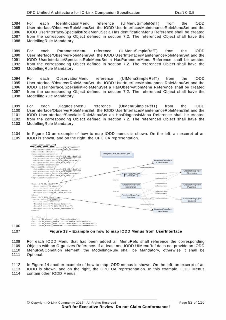
OPC Unified Architecture for IO-Link Companion Specification Draft 0.3.5
________________________________________________________________________________________________________ © Copyright IO-Link Community 2018 - All Rights Reserved Page 52 of 116
Draft for Executive Review. Do not Claim Conformance!
For each IdentificationMenu reference (UIMenuSimpleRefT) from the IODD 1084 UserInterface/ObserverRoleMenuSet, the IODD UserInterface/MaintenanceRoleMenuSet and the 1085 IODD UserInterface/SpecialistRoleMenuSet a HasIdentificationMenu Reference shall be created 1086 from the corresponding Object defined in section 7.2. The referenced Object shall have the 1087 ModellingRule Mandatory. 1088
For each ParameterMenu reference (UIMenuSimpleRefT) from the IODD 1089 UserInterface/ObserverRoleMenuSet, the IODD UserInterface/MaintenanceRoleMenuSet and the 1090 IODD UserInterface/SpecialistRoleMenuSet a HasParameterMenu Reference shall be created 1091 from the corresponding Object defined in section 7.2. The referenced Object shall have the 1092 ModellingRule Mandatory. 1093
For each ObservationMenu reference (UIMenuSimpleRefT) from the IODD 1094 UserInterface/ObserverRoleMenuSet, the IODD UserInterface/MaintenanceRoleMenuSet and the 1095 IODD UserInterface/SpecialistRoleMenuSet a HasObservationMenu Reference shall be created 1096 from the corresponding Object defined in section 7.2. The referenced Object shall have the 1097 ModellingRule Mandatory. 1098
For each DiagnosisMenu reference (UIMenuSimpleRefT) from the IODD 1099 UserInterface/ObserverRoleMenuSet, the IODD UserInterface/MaintenanceRoleMenuSet and the 1100 IODD UserInterface/SpecialistRoleMenuSet an HasDiagnosisMenu Reference shall be created 1101 from the corresponding Object defined in section 7.2. The referenced Object shall have the 1102 ModellingRule Mandatory. 1103
In Figure 13 an example of how to map IODD menus is shown. On the left, an excerpt of an 1104 IODD is shown, and on the right, the OPC UA representation. 1105
ExampleIOLinkIODDDeviceType
organizes
FunctionalGroupTypeObserver
FunctionalGroupTypeMaintenance
FunctionalGroupTypeSpecialist
organizes
organizes
HasIdentificationMenu
FunctionalGroupTypeIdentification
FunctionalGroupTypeObservationHasObserverMenu
FunctionalGroupTypeIdentification
FunctionalGroupTypeParameter
FunctionalGroupTypeDiagnosis
HasDiagnosisMenu
HasParameterMenu
...
HasObserverMenu
HasObserverMenu
HasParameterMenu
HasDiagnosisMenu
HasIdentificationMenu
HasIdentificationMenu
1106 Figure 13 – Example on how to map IODD Menus from UserInterface 1107
For each IODD Menu that has been added all MenuRefs shall reference the corresponding 1108 Objects with an Organizes Reference. If at least one IODD UIMenuRef does not provide an IODD 1109 MenuRef/Condition element, the ModellingRule shall be Mandatory, otherwise it shall be 1110 Optional. 1111
In Figure 14 another example of how to map IODD menus is shown. On the left, an excerpt of an 1112 IODD is shown, and on the right, the OPC UA representation. In this example, IODD Menus 1113 contain other IODD Menus. 1114
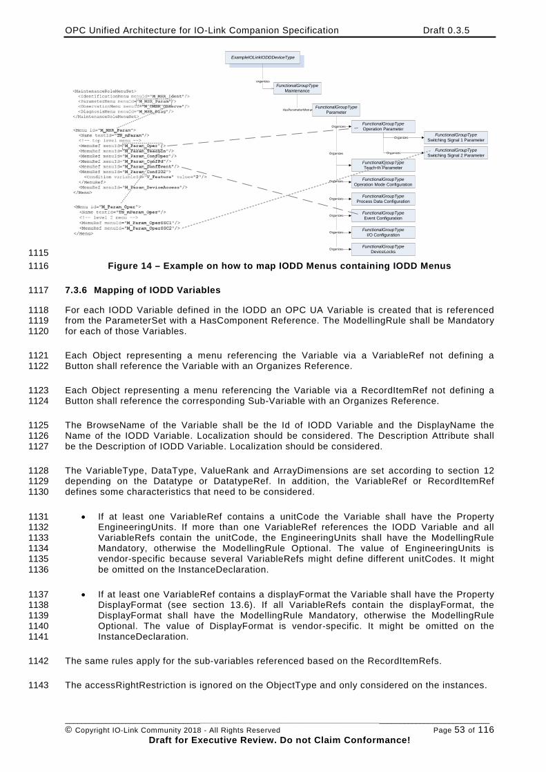
OPC Unified Architecture for IO-Link Companion Specification Draft 0.3.5
________________________________________________________________________________________________________ © Copyright IO-Link Community 2018 - All Rights Reserved Page 53 of 116
Draft for Executive Review. Do not Claim Conformance!
ExampleIOLinkIODDDeviceType
FunctionalGroupTypeMaintenance
organizes
FunctionalGroupTypeParameterHasParameterMenu
FunctionalGroupTypeOperation Parameter
FunctionalGroupType Teach-In Parameter
FunctionalGroupTypeOperation Mode Configuration
FunctionalGroupType Event Configuration
FunctionalGroupType I/O Configuration
FunctionalGroupType DeviceLocks
Organizes
Organizes
Organizes
Organizes
Organizes
Organizes
FunctionalGroupTypeSwitching Signal 1 Parameter
FunctionalGroupTypeSwitching Signal 2 Parameter
Organizes
Organizes
FunctionalGroupType Process Data Configuration
Organizes
1115 Figure 14 – Example on how to map IODD Menus containing IODD Menus 1116
7.3.6 Mapping of IODD Variables 1117
For each IODD Variable defined in the IODD an OPC UA Variable is created that is referenced 1118 from the ParameterSet with a HasComponent Reference. The ModellingRule shall be Mandatory 1119 for each of those Variables. 1120
Each Object representing a menu referencing the Variable via a VariableRef not defining a 1121 Button shall reference the Variable with an Organizes Reference. 1122
Each Object representing a menu referencing the Variable via a RecordItemRef not defining a 1123 Button shall reference the corresponding Sub-Variable with an Organizes Reference. 1124
The BrowseName of the Variable shall be the Id of IODD Variable and the DisplayName the 1125 Name of the IODD Variable. Localization should be considered. The Description Attribute shall 1126 be the Description of IODD Variable. Localization should be considered. 1127
The VariableType, DataType, ValueRank and ArrayDimensions are set according to section 12 1128 depending on the Datatype or DatatypeRef. In addition, the VariableRef or RecordItemRef 1129 defines some characteristics that need to be considered. 1130
• If at least one VariableRef contains a unitCode the Variable shall have the Property 1131 EngineeringUnits. If more than one VariableRef references the IODD Variable and all 1132 VariableRefs contain the unitCode, the EngineeringUnits shall have the ModellingRule 1133 Mandatory, otherwise the ModellingRule Optional. The value of EngineeringUnits is 1134 vendor-specific because several VariableRefs might define different unitCodes. It might 1135 be omitted on the InstanceDeclaration. 1136
• If at least one VariableRef contains a displayFormat the Variable shall have the Property 1137 DisplayFormat (see section 13.6). If all VariableRefs contain the displayFormat, the 1138 DisplayFormat shall have the ModellingRule Mandatory, otherwise the ModellingRule 1139 Optional. The value of DisplayFormat is vendor-specific. It might be omitted on the 1140 InstanceDeclaration. 1141
The same rules apply for the sub-variables referenced based on the RecordItemRefs. 1142
The accessRightRestriction is ignored on the ObjectType and only considered on the instances. 1143
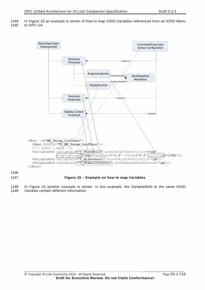
OPC Unified Architecture for IO-Link Companion Specification Draft 0.3.5
________________________________________________________________________________________________________ © Copyright IO-Link Community 2018 - All Rights Reserved Page 54 of 116
Draft for Executive Review. Do not Claim Conformance!
In Figure 15 an example is shown of how to map IODD Variables referenced from an IODD Menu 1144 to OPC UA. 1145
BaseObjectTypeParameterSet
FunctionalGroupTypeSensor Configuration
Detection Threshold Organizes
EngineeringUnits
DisplayFormat
Detection Hysteresis
Organizes
Stability Control Threshold Organizes
ModellingRuleMandatory
HasModellingRule
HasModellingRule
1146 Figure 15 – Example on how to map Variables 1147
In Figure 16 another example is shown. In this example, the VariableRefs to the same IODD 1148 Variable contain different information. 1149
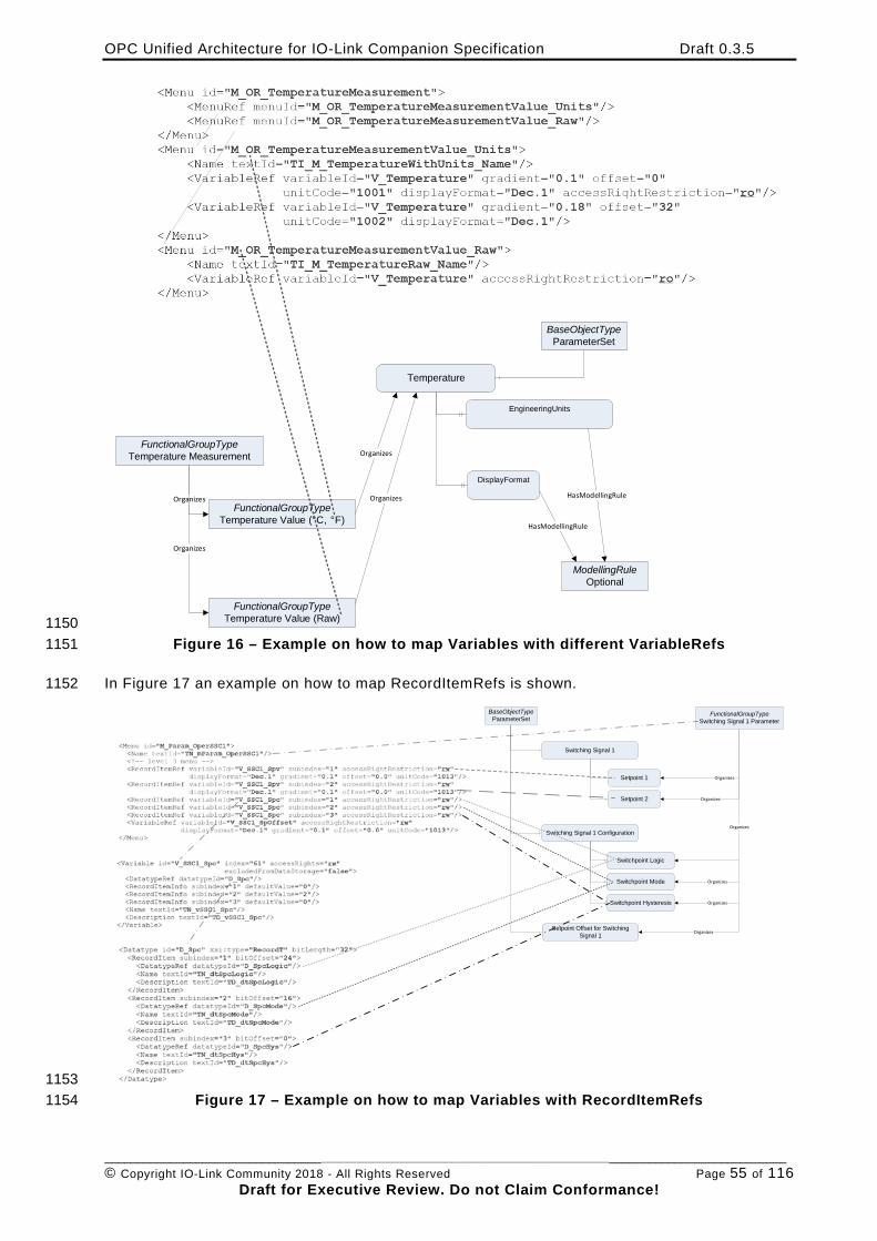
OPC Unified Architecture for IO-Link Companion Specification Draft 0.3.5
________________________________________________________________________________________________________ © Copyright IO-Link Community 2018 - All Rights Reserved Page 55 of 116
Draft for Executive Review. Do not Claim Conformance!
FunctionalGroupTypeTemperature Measurement
FunctionalGroupTypeTemperature Value (°C, °F)
Organizes
Organizes
Temperature
BaseObjectTypeParameterSet
Organizes
DisplayFormat
EngineeringUnits
FunctionalGroupTypeTemperature Value (Raw)
ModellingRuleOptional
HasModellingRule
HasModellingRuleOrganizes
1150 Figure 16 – Example on how to map Variables with different VariableRefs 1151
In Figure 17 an example on how to map RecordItemRefs is shown. 1152
BaseObjectTypeParameterSet
FunctionalGroupTypeSwitching Signal 1 Parameter
Switching Signal 1
OrganizesSetpoint 1
Setpoint 2
Switching Signal 1 Configuration
Switchpoint Logic
Switchpoint Mode
Switchpoint Hysteresis
Setpoint Offset for Switching Signal 1
Organizes
Organizes
Organizes
Organizes
Organizes
1153 Figure 17 – Example on how to map Variables with RecordItemRefs 1154
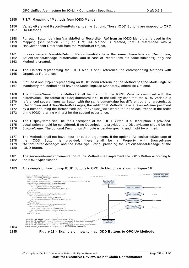
OPC Unified Architecture for IO-Link Companion Specification Draft 0.3.5
________________________________________________________________________________________________________ © Copyright IO-Link Community 2018 - All Rights Reserved Page 56 of 116
Draft for Executive Review. Do not Claim Conformance!
7.3.7 Mapping of Methods from IODD Menus 1155
VariableRefs and RecordItemRefs can define Buttons. Those IODD Buttons are mapped to OPC 1156 UA Methods. 1157
For each Button-defining VariableRef or RecordItemRef from an IODD Menu that is used in the 1158 mapping (see section 7.3.5) an OPC UA Method is created, that is referenced with a 1159 HasComponent Reference from the MethodSet Object. 1160
In case several VariableRefs or RecordItemRefs have the same characteristics (Description, 1161 ActionStartedMessage, buttonValue, and in case of RecordItemRefs same subindex), only one 1162 Method is created. 1163
The Objects representing the IODD Menus shall reference the corresponding Methods with 1164 Organizes References. 1165
If at least one Object representing an IODD Menu referencing the Method has the ModellingRule 1166 Mandatory the Method shall have the ModellingRule Mandatory, otherwise Optional. 1167
The BrowseName of the Method shall be the Id of the IODD Variable combined with the 1168 buttonValue. The format is “<Id>|<buttonValue>”. In the unlikely case that the IODD Variable is 1169 referenced several times as Button with the same buttonValue but different other characteristics 1170 (Description and ActionStartedMessage), the additional Methods have a BrowseName postfixed 1171 by a number using the format “<Id>|<buttonValue>_<n>” where “n” is the occurrence in the order 1172 of the IODD, starting with a 2 for the second occurrence. 1173
The DisplayName shall be the Description of the IODD Button, if a Description is provided. 1174 Localization should be considered. If no Description is provided, the DisplayName should be the 1175 BrowseName. The optional Description Attribute is vendor-specific and might be omitted. 1176
The Methods shall not have input- or output-arguments. If the optional ActionStartedMessage of 1177 the IODD Button is provided, there shall be a Property with BrowseName 1178 “ActionStartedMessage” and the DataType String, providing the ActionStartedMessage of the 1179 IODD Button. 1180
The server-internal implementation of the Method shall implement the IODD Button according to 1181 the IODD Specification. 1182
An example on how to map IODD Buttons to OPC UA Methods is shown in Figure 18. 1183
BaseObjectTypeMethodSet
FunctionGroupTypeTeach-In Parameter
Teach-In Setpoint 1
Teach-In Setpoint 2
Teach-In Measurement Offset
Organizes
Organizes
Organizes
BaseObjectTypeParameterSet
OrganizesTeach-in Channel
1184 Figure 18 – Example on how to map IODD Buttons to OPC UA Methods 1185
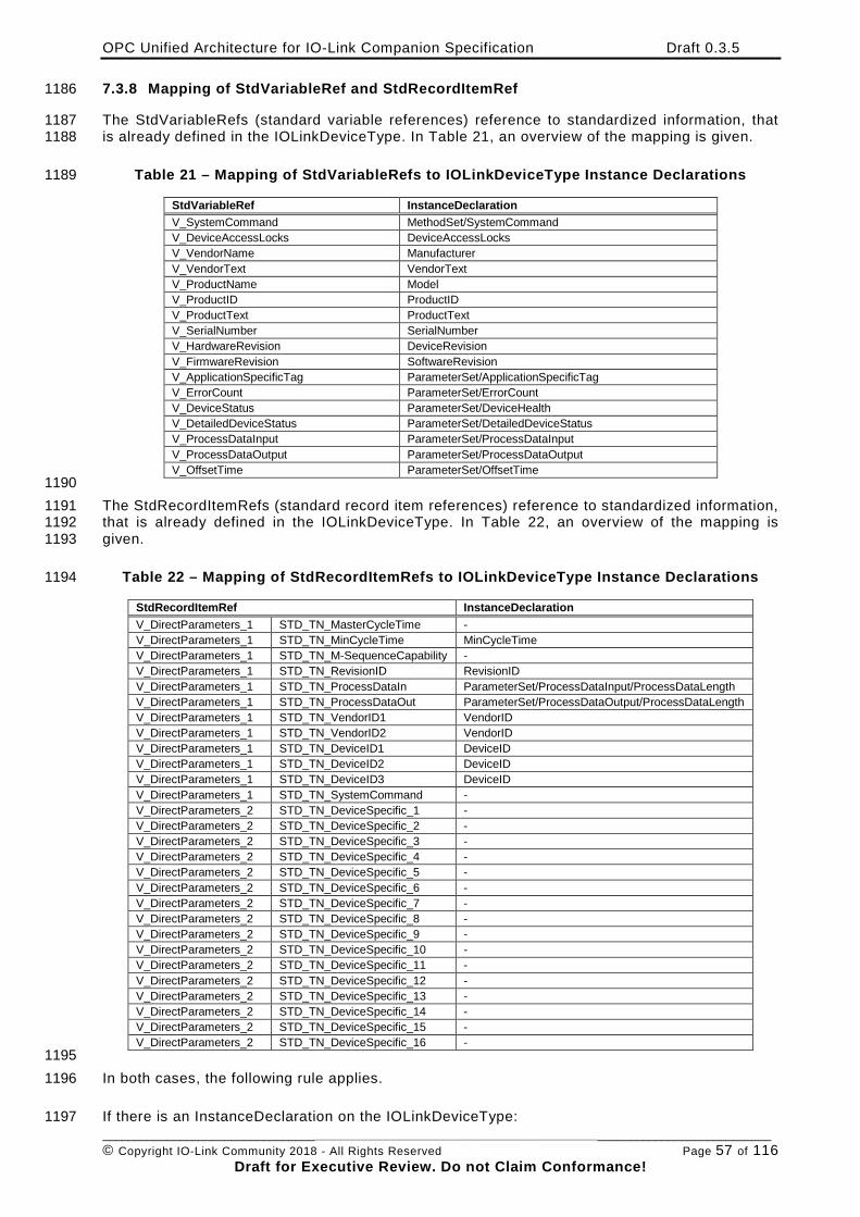
OPC Unified Architecture for IO-Link Companion Specification Draft 0.3.5
________________________________________________________________________________________________________ © Copyright IO-Link Community 2018 - All Rights Reserved Page 57 of 116
Draft for Executive Review. Do not Claim Conformance!
7.3.8 Mapping of StdVariableRef and StdRecordItemRef 1186
The StdVariableRefs (standard variable references) reference to standardized information, that 1187 is already defined in the IOLinkDeviceType. In Table 21, an overview of the mapping is given. 1188
Table 21 – Mapping of StdVariableRefs to IOLinkDeviceType Instance Declarations 1189
StdVariableRef InstanceDeclaration V_SystemCommand MethodSet/SystemCommand V_DeviceAccessLocks DeviceAccessLocks V_VendorName Manufacturer V_VendorText VendorText V_ProductName Model V_ProductID ProductID V_ProductText ProductText V_SerialNumber SerialNumber V_HardwareRevision DeviceRevision V_FirmwareRevision SoftwareRevision V_ApplicationSpecificTag ParameterSet/ApplicationSpecificTag V_ErrorCount ParameterSet/ErrorCount V_DeviceStatus ParameterSet/DeviceHealth V_DetailedDeviceStatus ParameterSet/DetailedDeviceStatus V_ProcessDataInput ParameterSet/ProcessDataInput V_ProcessDataOutput ParameterSet/ProcessDataOutput V_OffsetTime ParameterSet/OffsetTime
1190 The StdRecordItemRefs (standard record item references) reference to standardized information, 1191 that is already defined in the IOLinkDeviceType. In Table 22, an overview of the mapping is 1192 given. 1193
Table 22 – Mapping of StdRecordItemRefs to IOLinkDeviceType Instance Declarations 1194
StdRecordItemRef InstanceDeclaration V_DirectParameters_1 STD_TN_MasterCycleTime - V_DirectParameters_1 STD_TN_MinCycleTime MinCycleTime V_DirectParameters_1 STD_TN_M-SequenceCapability - V_DirectParameters_1 STD_TN_RevisionID RevisionID V_DirectParameters_1 STD_TN_ProcessDataIn ParameterSet/ProcessDataInput/ProcessDataLength V_DirectParameters_1 STD_TN_ProcessDataOut ParameterSet/ProcessDataOutput/ProcessDataLength V_DirectParameters_1 STD_TN_VendorID1 VendorID V_DirectParameters_1 STD_TN_VendorID2 VendorID V_DirectParameters_1 STD_TN_DeviceID1 DeviceID V_DirectParameters_1 STD_TN_DeviceID2 DeviceID V_DirectParameters_1 STD_TN_DeviceID3 DeviceID V_DirectParameters_1 STD_TN_SystemCommand - V_DirectParameters_2 STD_TN_DeviceSpecific_1 - V_DirectParameters_2 STD_TN_DeviceSpecific_2 - V_DirectParameters_2 STD_TN_DeviceSpecific_3 - V_DirectParameters_2 STD_TN_DeviceSpecific_4 - V_DirectParameters_2 STD_TN_DeviceSpecific_5 - V_DirectParameters_2 STD_TN_DeviceSpecific_6 - V_DirectParameters_2 STD_TN_DeviceSpecific_7 - V_DirectParameters_2 STD_TN_DeviceSpecific_8 - V_DirectParameters_2 STD_TN_DeviceSpecific_9 - V_DirectParameters_2 STD_TN_DeviceSpecific_10 - V_DirectParameters_2 STD_TN_DeviceSpecific_11 - V_DirectParameters_2 STD_TN_DeviceSpecific_12 - V_DirectParameters_2 STD_TN_DeviceSpecific_13 - V_DirectParameters_2 STD_TN_DeviceSpecific_14 - V_DirectParameters_2 STD_TN_DeviceSpecific_15 - V_DirectParameters_2 STD_TN_DeviceSpecific_16 -
1195 In both cases, the following rule applies. 1196
If there is an InstanceDeclaration on the IOLinkDeviceType: 1197
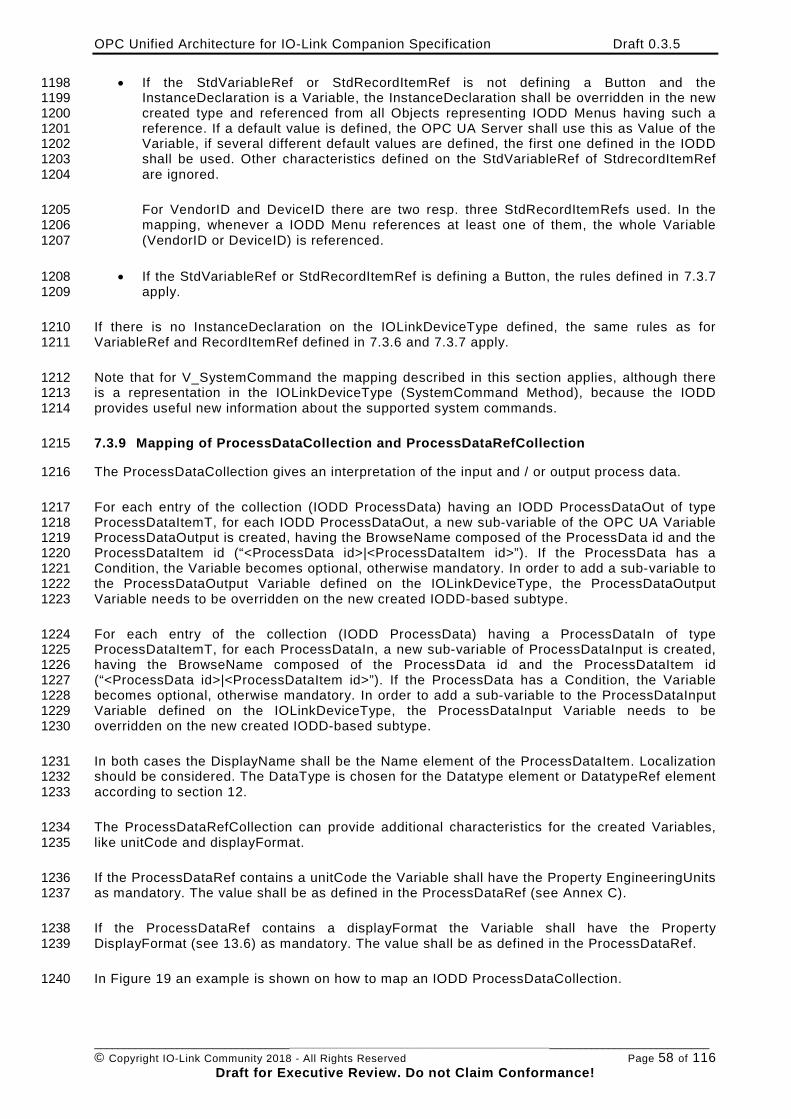
OPC Unified Architecture for IO-Link Companion Specification Draft 0.3.5
________________________________________________________________________________________________________ © Copyright IO-Link Community 2018 - All Rights Reserved Page 58 of 116
Draft for Executive Review. Do not Claim Conformance!
• If the StdVariableRef or StdRecordItemRef is not defining a Button and the 1198 InstanceDeclaration is a Variable, the InstanceDeclaration shall be overridden in the new 1199 created type and referenced from all Objects representing IODD Menus having such a 1200 reference. If a default value is defined, the OPC UA Server shall use this as Value of the 1201 Variable, if several different default values are defined, the first one defined in the IODD 1202 shall be used. Other characteristics defined on the StdVariableRef of StdrecordItemRef 1203 are ignored. 1204
For VendorID and DeviceID there are two resp. three StdRecordItemRefs used. In the 1205 mapping, whenever a IODD Menu references at least one of them, the whole Variable 1206 (VendorID or DeviceID) is referenced. 1207
• If the StdVariableRef or StdRecordItemRef is defining a Button, the rules defined in 7.3.7 1208 apply. 1209
If there is no InstanceDeclaration on the IOLinkDeviceType defined, the same rules as for 1210 VariableRef and RecordItemRef defined in 7.3.6 and 7.3.7 apply. 1211
Note that for V_SystemCommand the mapping described in this section applies, although there 1212 is a representation in the IOLinkDeviceType (SystemCommand Method), because the IODD 1213 provides useful new information about the supported system commands. 1214
7.3.9 Mapping of ProcessDataCollection and ProcessDataRefCollection 1215
The ProcessDataCollection gives an interpretation of the input and / or output process data. 1216
For each entry of the collection (IODD ProcessData) having an IODD ProcessDataOut of type 1217 ProcessDataItemT, for each IODD ProcessDataOut, a new sub-variable of the OPC UA Variable 1218 ProcessDataOutput is created, having the BrowseName composed of the ProcessData id and the 1219 ProcessDataItem id (“<ProcessData id>|<ProcessDataItem id>”). If the ProcessData has a 1220 Condition, the Variable becomes optional, otherwise mandatory. In order to add a sub-variable to 1221 the ProcessDataOutput Variable defined on the IOLinkDeviceType, the ProcessDataOutput 1222 Variable needs to be overridden on the new created IODD-based subtype. 1223
For each entry of the collection (IODD ProcessData) having a ProcessDataIn of type 1224 ProcessDataItemT, for each ProcessDataIn, a new sub-variable of ProcessDataInput is created, 1225 having the BrowseName composed of the ProcessData id and the ProcessDataItem id 1226 (“<ProcessData id>|<ProcessDataItem id>”). If the ProcessData has a Condition, the Variable 1227 becomes optional, otherwise mandatory. In order to add a sub-variable to the ProcessDataInput 1228 Variable defined on the IOLinkDeviceType, the ProcessDataInput Variable needs to be 1229 overridden on the new created IODD-based subtype. 1230
In both cases the DisplayName shall be the Name element of the ProcessDataItem. Localization 1231 should be considered. The DataType is chosen for the Datatype element or DatatypeRef element 1232 according to section 12. 1233
The ProcessDataRefCollection can provide additional characteristics for the created Variables, 1234 like unitCode and displayFormat. 1235
If the ProcessDataRef contains a unitCode the Variable shall have the Property EngineeringUnits 1236 as mandatory. The value shall be as defined in the ProcessDataRef (see Annex C). 1237
If the ProcessDataRef contains a displayFormat the Variable shall have the Property 1238 DisplayFormat (see 13.6) as mandatory. The value shall be as defined in the ProcessDataRef. 1239
In Figure 19 an example is shown on how to map an IODD ProcessDataCollection. 1240
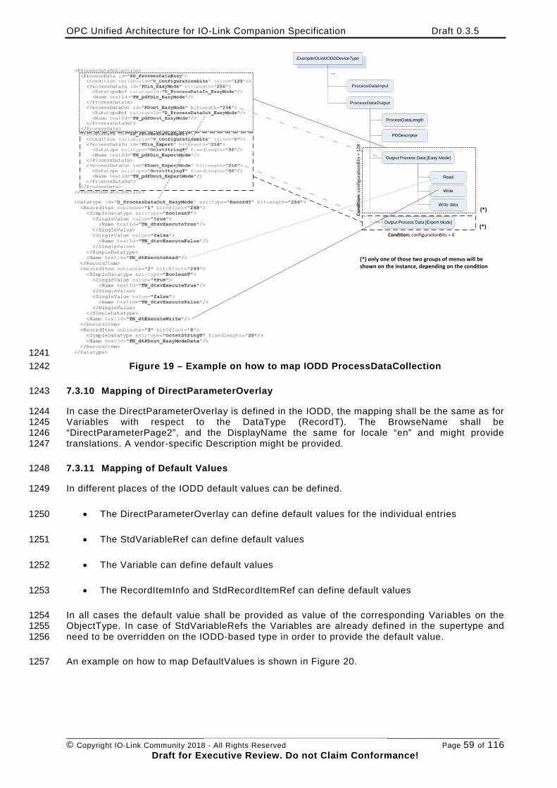
OPC Unified Architecture for IO-Link Companion Specification Draft 0.3.5
________________________________________________________________________________________________________ © Copyright IO-Link Community 2018 - All Rights Reserved Page 59 of 116
Draft for Executive Review. Do not Claim Conformance!
ExampleIOLinkIODDDeviceType
ProcessDataInput
ProcessDataOutput
...
ProcessDataLength
PDDescriptor
Output Process Data [Easy Mode]
Output Process Data [Expert Mode]
Read
Write
Write data
Cond
ition
: con
figur
atio
nBits
= 1
28
(*)
Condition: configurationBits = 0(*)
(*) only one of those two groups of menus will be shown on the instance, depending on the condition
1241 Figure 19 – Example on how to map IODD ProcessDataCollection 1242
7.3.10 Mapping of DirectParameterOverlay 1243
In case the DirectParameterOverlay is defined in the IODD, the mapping shall be the same as for 1244 Variables with respect to the DataType (RecordT). The BrowseName shall be 1245 “DirectParameterPage2”, and the DisplayName the same for locale “en” and might provide 1246 translations. A vendor-specific Description might be provided. 1247
7.3.11 Mapping of Default Values 1248
In different places of the IODD default values can be defined. 1249
• The DirectParameterOverlay can define default values for the individual entries 1250
• The StdVariableRef can define default values 1251
• The Variable can define default values 1252
• The RecordItemInfo and StdRecordItemRef can define default values 1253
In all cases the default value shall be provided as value of the corresponding Variables on the 1254 ObjectType. In case of StdVariableRefs the Variables are already defined in the supertype and 1255 need to be overridden on the IODD-based type in order to provide the default value. 1256
An example on how to map DefaultValues is shown in Figure 20. 1257
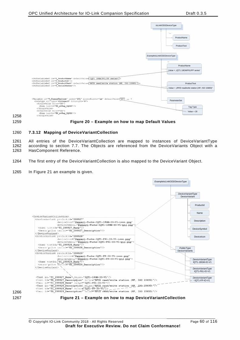
OPC Unified Architecture for IO-Link Companion Specification Draft 0.3.5
________________________________________________________________________________________________________ © Copyright IO-Link Community 2018 - All Rights Reserved Page 60 of 116
Draft for Executive Review. Do not Claim Conformance!
IoLinkIODDDeviceType
ProductName
ProductText
ExampleIoLinkIODDDeviceType
...
ProductName
ProductText
...
ParameterSet
Tag Type
Value = „IQT1 18GM/F61/FP series“
Value = „RFID read/write station (HF, ISO 15693)“
Value = 20
1258 Figure 20 – Example on how to map Default Values 1259
7.3.12 Mapping of DeviceVariantCollection 1260
All entries of the DeviceVariantCollection are mapped to instances of DeviceVariantType 1261 according to section 7.7. The Objects are referenced from the DeviceVariants Object with a 1262 HasComponent Reference. 1263
The first entry of the DeviceVariantCollection is also mapped to the DeviceVariant Object. 1264
In Figure 21 an example is given. 1265
ExampleIoLinkIODDDeviceType
DeviceVariantTypeDeviceVariant
FolderTypeDeviceVariants
DeviceVariantTypeIQT1-18GM-IO-V1
DeviceVariantTypeIQT1-F61-IO-V1
DeviceVariantTypeIQT1-FP-IO-V1
ProductId
Description
Name
DeviceIcon
DeviceSymbol
1266 Figure 21 – Example on how to map DeviceVariantCollection 1267
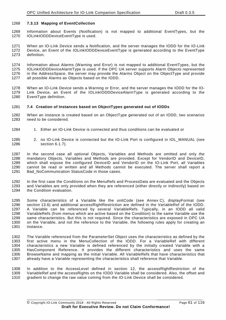
OPC Unified Architecture for IO-Link Companion Specification Draft 0.3.5
________________________________________________________________________________________________________ © Copyright IO-Link Community 2018 - All Rights Reserved Page 61 of 116
Draft for Executive Review. Do not Claim Conformance!
7.3.13 Mapping of EventCollection 1268
Information about Events (Notification) is not mapped to additional EventTypes, but the 1269 IOLinkIODDDeviceEventType is used. 1270
When an IO-Link Device sends a Notification, and the server manages the IODD for the IO-Link 1271 Device, an Event of the IOLinkIODDDeviceEventType is generated according to the EventType 1272 definition. 1273
Information about Alarms (Warning and Error) is not mapped to additional EventTypes, but the 1274 IOLinkIODDDeviceAlarmType is used. If the OPC UA server supports Alarm Objects represented 1275 in the AddressSpace, the server may provide the Alarms Object on the ObjectType and provide 1276 all possible Alarms as Objects based on the IODD. 1277
When an IO-Link Device sends a Warning or Error, and the server manages the IODD for the IO-1278 Link Device, an Event of the IOLinkIODDDeviceAlarmType is generated according to the 1279 EventType definition. 1280
7.4 Creation of Instances based on ObjectTypes generated out of IODDs 1281
When an instance is created based on an ObjectType generated out of an IODD, two scenarios 1282 need to be considered. 1283
1. Either an IO-Link Device is connected and thus conditions can be evaluated or 1284
2. no IO-Link Device is connected but the IO-Link Port is configured in IOL_MANUAL (see 1285 section 6.1.7). 1286
In the second case all optional Objects, Variables and Methods are omitted and only the 1287 mandatory Objects, Variables and Methods are provided. Except for VendorID and DeviceID, 1288 which shall expose the configured DeviceID and VendorID on the IO-Link Port, all Variables 1289 cannot be read or written and all Methods cannot be executed. The server shall report a 1290 Bad_NoCommunication StatusCode in those cases. 1291
In the first case the Conditions on the MenuRefs and ProcessData are evaluated and the Objects 1292 and Variables are only provided when they are referenced (either directly or indirectly) based on 1293 the Condition evaluation. 1294
Some characteristics of a Variable like the unitCode (see Annex C), displayFormat (see 1295 section 13.6) and additional accessRightRestriction are defined in the VariableRef of the IODD. 1296 A Variable can be referenced by several VariableRefs. Typically, in an IODD all valid 1297 VariableRefs (from menus which are active based on the Condition) to the same Variable use the 1298 same characteristics. But this is not required. Since the characteristics are exposed in OPC UA 1299 on the Variable, and not the reference to the Variable, the following rules apply for creating an 1300 instance. 1301
The Variable referenced from the ParameterSet Object uses the characteristics as defined by the 1302 first active menu in the MenuCollection of the IODD. For a VariableRef with different 1303 characteristics a new Variable is defined referenced by the initially created Variable with a 1304 HasComponent Reference. It provides the different characteristics and uses the same 1305 BrowseName and mapping as the initial Variable. All VariableRefs that have characteristics that 1306 already have a Variable representing the characteristics shall reference that Variable. 1307
In addition to the AccessLevel defined in section 12, the accessRightRestriction of the 1308 VariableRef and the accessRights on the IODD Variable shall be considered. Also, the offset and 1309 gradient to change the raw value coming from the IO-Link Device shall be considered. 1310
OPC Unified Architecture for IO-Link Companion Specification Draft 0.3.5
________________________________________________________________________________________________________ © Copyright IO-Link Community 2018 - All Rights Reserved Page 62 of 116
Draft for Executive Review. Do not Claim Conformance!
In case the raw value is changed in the Variable (offset and/or gradient are defined in the IODD), 1311 there shall be a Sub-Variable on the OPC UA Variable instance with the BrowseName 1312 “RawValue” providing the raw value from the IO-Link Device. 1313
When the IODD provides default values for a Variable in OPC UA, and the server has not 1314 already read the value from the IO-Link Device, the default value should be provided with 1315 StatusCode Uncertain_InitialValue. 1316
The DeviceVariant Object is filled with the DeviceVariant according to the ProductID of the IO-1317 Link Device. If the IO-Link Device does not provide this optional parameter or ProductID does 1318 not correspond to a DeviceVariant specified in the IODD, the OPC UA Server shall use the first 1319 DeviceVariant defined in the IODD. 1320
If the optional DeviceSymbol or DeviceIcon Variable exist on the DeviceVariant Object, the 1321 DeviceTypeImage Folder defined in OPC UA Part 100 shall be provided. The DeviceTypeImage 1322 Folder shall reference the DeviceSymbol and the DeviceIcon with a HasComponent Reference if 1323 those Variables are provided on the DeviceVaraint Object. 1324
When the blockParameter attribute is defined and set to “False” in the IODD, the Methods 1325 ParamUploadFromDeviceStart, ParamUploadFromDeviceStop, ParamDownloadToDeviceStart, 1326 ParamDownloadToDeviceStop, and ParamBreak shall have the Executable Attribute set to 1327 “False”. 1328
When the dataStorage attribute is defined and set to “False” in the IODD, the Method 1329 ParamDownloadToDeviceStore shall have the Executable Attribute set to “False”. 1330
In Figure 22 an example of an Object based on an IODD is shown. 1331
1332
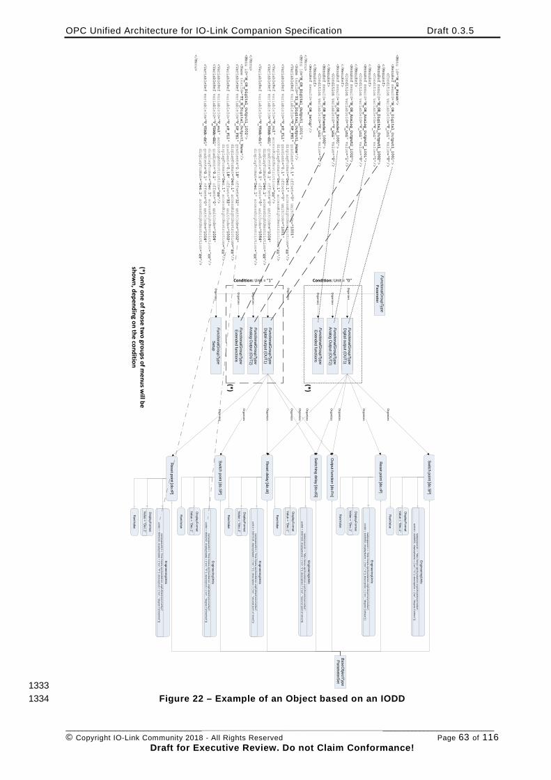
OPC Unified Architecture for IO-Link Companion Specification Draft 0.3.5
________________________________________________________________________________________________________ © Copyright IO-Link Community 2018 - All Rights Reserved Page 63 of 116
Draft for Executive Review. Do not Claim Conformance!
FunctionalGroupType
Parameter
FunctionalGroupType
M_O
R_digital_output1_1001
FunctionalGroupType
Digital output (O
UT1)
FunctionalGroupType
Analog Output (O
UT2)
FunctionalGroupType
Extended functions
FunctionalGroupType
M_O
R_digital_output1_1001
FunctionalGroupType
Digital output (O
UT1)
FunctionalGroupType
Analog Output (O
UT2)
FunctionalGroupType
Extended functions
FunctionalGroupType
Setup
Organizes
Organizes
Organizes
Organizes
Organizes
Organizes
Organizes
Switch point [do.SP]
Reset point [do.rP]
Output function [do.Fn]
Switching delay [do.dS]
Reset delay [do.dr]
Switch point [do.SP]
Reset point [do.rP]
BaseO
bjectTypeParam
eterSet
Organizes
Organizes
Organizes
Organizes
Organizes
Organizes
Organizes
Organizes
Organizes
Organizes
Raw
Value
DisplayForm
at
Value = “Dec.1”
Raw
Value
DisplayForm
at
Value = “Dec.1”
Raw
Value
DisplayForm
at
Value = “Dec.1”
Raw
Value
DisplayForm
at
Value = “Dec.1”
Raw
Value
DisplayForm
at
Value = “Dec.1”
Raw
Value
DisplayForm
at
Value = “Dec.1”
EngineeringUnits
namespaceU
ri = “http://w
ww
.opcfoundation.org/UA
/units/un/cefact”;unitId = 5457219; displayN
ame =
{“en”,"s"}; description = {“en”, "second [unit of time]"}}
EngineeringUnits
namespaceU
ri = “http://w
ww
.opcfoundation.org/UA
/units/un/cefact”;unitId = 5457219; displayN
ame =
{“en”,"s"}; description = {“en”, "second [unit of time]"}}
EngineeringUnits
namespaceU
ri = “http://w
ww
.opcfoundation.org/UA
/units/un/cefact”;unitId = 4408652; displayN
ame =
{“en”,"°C"}; description = {“en”, "degree C
elsius"}}
EngineeringUnits
namespaceU
ri = “http://w
ww
.opcfoundation.org/UA
/units/un/cefact”;unitId = 4408652; displayN
ame =
{“en”,"°C"}; description = {“en”, "degree C
elsius"}}
EngineeringUnits
namespaceU
ri = “http://w
ww
.opcfoundation.org/UA
/units/un/cefact”;unitId = 4604232; displayN
ame =
{“en”,"°F"}; description =
{“en”, "degree Fahrenheit"}}
EngineeringUnits
namespaceU
ri = “http://w
ww
.opcfoundation.org/UA
/units/un/cefact”;unitId = 4604232; displayN
ame =
{“en”,"°F"}; description =
{“en”, "degree Fahrenheit"}}
Condition: Unit = “1” Condition: Unit = “0”
(*)
(*)
(*) only one of those two groups of m
enus will be
shown, depending on the condition
1333 Figure 22 – Example of an Object based on an IODD 1334
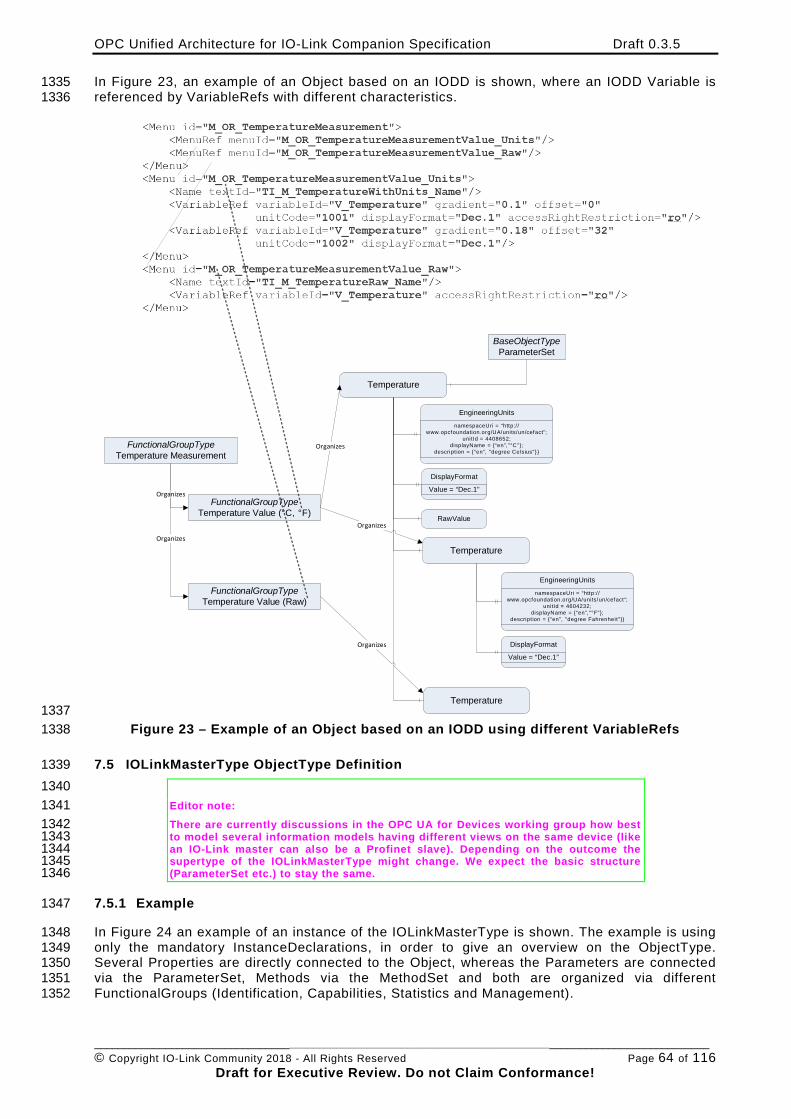
OPC Unified Architecture for IO-Link Companion Specification Draft 0.3.5
________________________________________________________________________________________________________ © Copyright IO-Link Community 2018 - All Rights Reserved Page 64 of 116
Draft for Executive Review. Do not Claim Conformance!
In Figure 23, an example of an Object based on an IODD is shown, where an IODD Variable is 1335 referenced by VariableRefs with different characteristics. 1336
FunctionalGroupTypeTemperature Measurement
FunctionalGroupTypeTemperature Value (°C, °F)
Organizes
Organizes
Temperature
Temperature
BaseObjectTypeParameterSet
Organizes
DisplayFormat
Value = “Dec.1”
EngineeringUnits
namespaceUri = “http:/ /www.opcfoundation.org/UA/units/un/cefact”;
unitId = 4408652;displayName = {“en”,"°C"};
descript ion = {“en”, "degree Celsius"}}
FunctionalGroupTypeTemperature Value (Raw)
Organizes
Temperature
RawValue
DisplayFormat
Value = “Dec.1”
EngineeringUnits
namespaceUri = “http:/ /www.opcfoundation.org/UA/units/un/cefact”;
unitId = 4604232;displayName = {“en”,"°F"};
descript ion = {“en”, "degree Fahrenheit"}}
Organizes
1337 Figure 23 – Example of an Object based on an IODD using different VariableRefs 1338
7.5 IOLinkMasterType ObjectType Definition 1339 1340 Editor note: 1341 There are currently discussions in the OPC UA for Devices working group how best 1342 to model several information models having different views on the same device (like 1343 an IO-Link master can also be a Profinet slave). Depending on the outcome the 1344 supertype of the IOLinkMasterType might change. We expect the basic structure 1345 (ParameterSet etc.) to stay the same. 1346
7.5.1 Example 1347
In Figure 24 an example of an instance of the IOLinkMasterType is shown. The example is using 1348 only the mandatory InstanceDeclarations, in order to give an overview on the ObjectType. 1349 Several Properties are directly connected to the Object, whereas the Parameters are connected 1350 via the ParameterSet, Methods via the MethodSet and both are organized via different 1351 FunctionalGroups (Identification, Capabilities, Statistics and Management). 1352
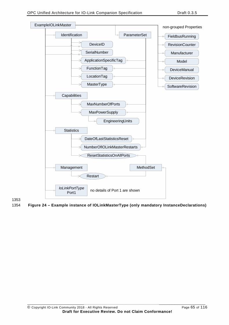
OPC Unified Architecture for IO-Link Companion Specification Draft 0.3.5
________________________________________________________________________________________________________ © Copyright IO-Link Community 2018 - All Rights Reserved Page 65 of 116
Draft for Executive Review. Do not Claim Conformance!
ExampleIOLinkMaster
FieldbusRunningIdentification
DeviceID
SerialNumber
ApplicationSpecificTag
FunctionTag
LocationTag
non-grouped Properties
RevisionCounter
Manufacturer
Model
DeviceManual
SoftwareRevision
DeviceRevision
Capabilities
MaxNumberOfPorts
MaxPowerSupply
Restart
ResetStatisticsOnAllPorts
IoLinkPortTypePort1
ParameterSet
MethodSet
MasterType
Statistics
DateOfLastStatisticsReset
NumberOfIOLinkMasterRestarts
Management
no details of Port 1 are shown
EngineeringUnits
1353 Figure 24 – Example instance of IOLinkMasterType (only mandatory InstanceDeclarations) 1354
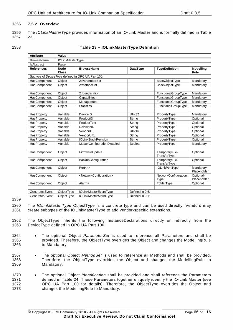
OPC Unified Architecture for IO-Link Companion Specification Draft 0.3.5
________________________________________________________________________________________________________ © Copyright IO-Link Community 2018 - All Rights Reserved Page 66 of 116
Draft for Executive Review. Do not Claim Conformance!
7.5.2 Overview 1355
The IOLinkMasterType provides information of an IO-Link Master and is formally defined in Table 1356 23. 1357
Table 23 – IOLinkMasterType Definition 1358
Attribute Value BrowseName IOLinkMasterType IsAbstract False References Node
Class BrowseName DataType TypeDefinition Modelling
Rule Subtype of DeviceType defined in OPC UA Part 100. HasComponent Object 2:ParameterSet BaseObjectType Mandatory HasComponent Object 2:MethodSet BaseObjectType Mandatory HasComponent Object 2:Identification FunctionalGroupType Mandatory HasComponent Object Capabilities FunctionalGroupType Mandatory HasComponent Object Management FunctionalGroupType Mandatory HasComponent Object Statistics FunctionalGroupType Mandatory HasProperty Variable DeviceID UInt32 PropertyType Mandatory HasProperty Variable ProductID String PropertyType Optional HasProperty Variable ProductText String PropertyType Optional HasProperty Variable RevisionID String PropertyType Optional HasProperty Variable VendorID UInt16 PropertyType Optional HasProperty Variable VendorURL String PropertyType Optional HasProperty Variable IOLinkStackRevision String PropertyType Optional HasProperty Variable MasterConfigurationDisabled Boolean PropertyType Mandatory HasComponent Object FirmwareUpdate TemporaryFile-
TransferType Optional
HasComponent Object BackupConfiguration TemporaryFile-TransferType
Optional
HasComponent Object Port<n> IOLinkPortType Mandatory-Placeholder
HasComponent Object <NetworkConfiguration> NetworkConfigurationType
Optional- Placeholder
HasComponent Object Alarms FolderType Optional GeneratesEvent ObjectType IOLinkMasterEventType Defined in 9.6. GeneratesEvent ObjectType IOLinkMasterAlarmType Defined in 9.11.
1359 The IOLinkMasterType ObjectType is a concrete type and can be used directly. Vendors may 1360 create subtypes of the IOLinkMasterType to add vendor-specific extensions. 1361
The ObjectType inherits the following InstanceDeclarations directly or indirectly from the 1362 DeviceType defined in OPC UA Part 100. 1363
• The optional Object ParameterSet is used to reference all Parameters and shall be 1364 provided. Therefore, the ObjectType overrides the Object and changes the ModellingRule 1365 to Mandatory. 1366
• The optional Object MethodSet is used to reference all Methods and shall be provided. 1367 Therefore, the ObjectType overrides the Object and changes the ModellingRule to 1368 Mandatory. 1369
• The optional Object Identification shall be provided and shall reference the Parameters 1370 defined in Table 24. Those Parameters together uniquely identify the IO-Link Master (see 1371 OPC UA Part 100 for details). Therefore, the ObjectType overrides the Object and 1372 changes the ModellingRule to Mandatory. 1373
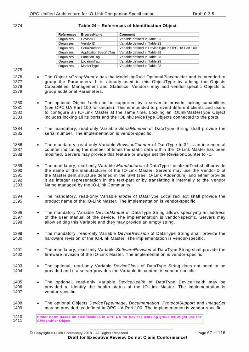
OPC Unified Architecture for IO-Link Companion Specification Draft 0.3.5
________________________________________________________________________________________________________ © Copyright IO-Link Community 2018 - All Rights Reserved Page 67 of 116
Draft for Executive Review. Do not Claim Conformance!
Table 24 – References of Identification Object 1374
References BrowseName Comment Organizes DeviceID Variable defined in Table 23 Organizes VendorID Variable defined in Table 23 Organizes SerialNumber Variable defined in DeviceType in OPC UA Part 100 Organizes ApplicationSpecificTag Variable defined in Table 28 Organizes FunctionTag Variable defined in Table 28 Organizes LocationTag Variable defined in Table 28 Organizes MasterType Variable defined in Table 28
1375 • The Object <GroupName> has the ModellingRule OptionalPlaceholder and is intended to 1376
group the Parameters. It is already used in this ObjectType by adding the Objects 1377 Capabilities, Management and Statistics. Vendors may add vendor-specific Objects to 1378 group additional Parameters. 1379
• The optional Object Lock can be supported by a server to provide locking capabilities 1380 (see OPC UA Part 100 for details). This is intended to prevent different clients and users 1381 to configure an IO-Link Master at the same time. Locking an IOLinkMasterType Object 1382 includes locking all its ports and the IOLinkDeviceType Objects connected to the ports. 1383
• The mandatory, read-only Variable SerialNumber of DataType String shall provide the 1384 serial number. The implementation is vendor-specific. 1385
• The mandatory, read-only Variable RevisionCounter of DataType Int32 is an incremental 1386 counter indicating the number of times the static data within the IO-Link Master has been 1387 modified. Servers may provide this feature or always set the RevisionCounter to -1. 1388
• The mandatory, read-only Variable Manufacturer of DataType LocalizedText shall provide 1389 the name of the manufacturer of the IO-Link Master. Servers may use the VendorID of 1390 the MasterIdent structure defined in the SMI (see IO-Link Addendum) and either provide 1391 it as integer representation in the text-part or by translating it internally to the Vendor 1392 Name managed by the IO-Link Community. 1393
• The mandatory, read-only Variable Model of DataType LocalizedText shall provide the 1394 product name of the IO-Link Master. The implementation is vendor-specific. 1395
• The mandatory Variable DeviceManual of DataType String allows specifying an address 1396 of the user manual of the device. The implementation is vendor-specific. Servers may 1397 allow editing this Variable and they may provide an empty string. 1398
• The mandatory, read-only Variable DeviceRevision of DataType String shall provide the 1399 hardware revision of the IO-Link Master. The implementation is vendor-specific. 1400
• The mandatory, read-only Variable SoftwareRevision of DataType String shall provide the 1401 firmware revision of the IO-Link Master. The implementation is vendor-specific. 1402
• The optional, read-only Variable DeviceClass of DataType String does not need to be 1403 provided and if a server provides the Variable its content is vendor-specific. 1404
• The optional, read-only Variable DeviceHealth of DataType DeviceHealth may be 1405 provided to identify the health status of the IO-Link Master. The implementation is 1406 vendor-specific. 1407
• The optional Objects DeviceTypeImage, Documentation, ProtocolSupport and ImageSet 1408 may be provided as defined in OPC UA Part 100. The implementation is vendor-specific. 1409
Editor note: Based on clarifications in OPC UA for Devices working group we might use the 1410 CPIdentifier Object 1411
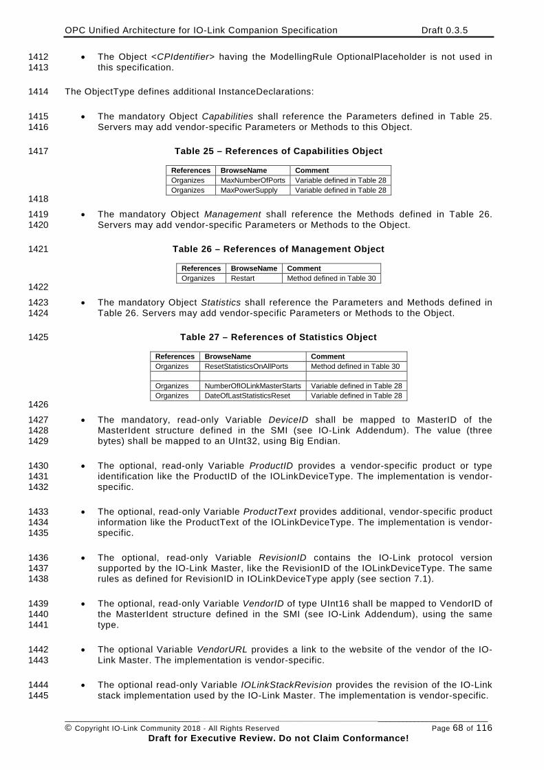
OPC Unified Architecture for IO-Link Companion Specification Draft 0.3.5
________________________________________________________________________________________________________ © Copyright IO-Link Community 2018 - All Rights Reserved Page 68 of 116
Draft for Executive Review. Do not Claim Conformance!
• The Object <CPIdentifier> having the ModellingRule OptionalPlaceholder is not used in 1412 this specification. 1413
The ObjectType defines additional InstanceDeclarations: 1414
• The mandatory Object Capabilities shall reference the Parameters defined in Table 25. 1415 Servers may add vendor-specific Parameters or Methods to this Object. 1416
Table 25 – References of Capabilities Object 1417
References BrowseName Comment Organizes MaxNumberOfPorts Variable defined in Table 28 Organizes MaxPowerSupply Variable defined in Table 28
1418 • The mandatory Object Management shall reference the Methods defined in Table 26. 1419
Servers may add vendor-specific Parameters or Methods to the Object. 1420
Table 26 – References of Management Object 1421
References BrowseName Comment Organizes Restart Method defined in Table 30
1422 • The mandatory Object Statistics shall reference the Parameters and Methods defined in 1423
Table 26. Servers may add vendor-specific Parameters or Methods to the Object. 1424
Table 27 – References of Statistics Object 1425
References BrowseName Comment Organizes ResetStatisticsOnAllPorts Method defined in Table 30 Organizes NumberOfIOLinkMasterStarts Variable defined in Table 28 Organizes DateOfLastStatisticsReset Variable defined in Table 28
1426 • The mandatory, read-only Variable DeviceID shall be mapped to MasterID of the 1427
MasterIdent structure defined in the SMI (see IO-Link Addendum). The value (three 1428 bytes) shall be mapped to an UInt32, using Big Endian. 1429
• The optional, read-only Variable ProductID provides a vendor-specific product or type 1430 identification like the ProductID of the IOLinkDeviceType. The implementation is vendor-1431 specific. 1432
• The optional, read-only Variable ProductText provides additional, vendor-specific product 1433 information like the ProductText of the IOLinkDeviceType. The implementation is vendor-1434 specific. 1435
• The optional, read-only Variable RevisionID contains the IO-Link protocol version 1436 supported by the IO-Link Master, like the RevisionID of the IOLinkDeviceType. The same 1437 rules as defined for RevisionID in IOLinkDeviceType apply (see section 7.1). 1438
• The optional, read-only Variable VendorID of type UInt16 shall be mapped to VendorID of 1439 the MasterIdent structure defined in the SMI (see IO-Link Addendum), using the same 1440 type. 1441
• The optional Variable VendorURL provides a link to the website of the vendor of the IO-1442 Link Master. The implementation is vendor-specific. 1443
• The optional read-only Variable IOLinkStackRevision provides the revision of the IO-Link 1444 stack implementation used by the IO-Link Master. The implementation is vendor-specific. 1445
OPC Unified Architecture for IO-Link Companion Specification Draft 0.3.5
________________________________________________________________________________________________________ © Copyright IO-Link Community 2018 - All Rights Reserved Page 69 of 116
Draft for Executive Review. Do not Claim Conformance!
• The mandatory Variable MasterConfigurationDisabled indicates whether configuration 1446 changes are allowed via OPC UA. If set to “True”, nearly all configuration settings 1447 become read-only and cannot be changed via OPC UA anymore. The Variable setting is 1448 vendor-specific, including whether it can be changed via OPC UA. For example, if a 1449 fieldbus is currently active on the IO-Link Master, a server might set this Variable to 1450 “True”. 1451
That includes in detail following rules: 1452
o The Method Restart of the IO-Link Master becomes not executable. 1453
o For all Ports of the IO-Link Master the Method UpdateConfiguration becomes not 1454 executable. 1455
o For all Ethernet configurations connected to the Fieldbus the configuration 1456 becomes read-only. 1457
The Method ResetStatistics on the Port and ResetStatisticsOnAllPorts on the IO-Link 1458 Master shall still be executable. 1459
There is no direct relation between the MasterConfigurationDisabled Variable and the 1460 Lock Object. The Lock Objects prevents different OPC UA Clients to configure the IO-1461 Link Master at the same time whereas the MasterConfigurationDisabled Variable 1462 indicates that the IO-Link Master is in a state within it cannot be configured by any OPC 1463 UA Client. When the MasterConfigurationDisabled Variable is set to “True” Servers may 1464 prevent the usage of the Lock Object for all Clients. 1465
• The Port<n> Object of ModellingRule MandatoryPlaceholder represents the ports of the 1466 IO-Link Master. For each port of the IO-Link Master one Object of type IOLinkPortType 1467 shall be provided, where <n> represents the number of the port. For example, a master 1468 having two ports has the Objects Port1 and Port2. How the counting starts (e.g. Port0 or 1469 Port1) is vendor-specific. 1470
1471 Editor note: 1472 DI group might standardize FirmwareUpdate and BackupConfiguration. In this case 1473 this specification will be updated using the definitions of the DI (OPC UA for 1474 Devices) specification. 1475
• The optional FirmwareUpdate Object is used to load a new firmware version into the 1476 server, and optionally, to read the current firmware version from the server. This is done 1477 by using the temporary file transfer mechanism (see OPC UA Part 5 for details on the 1478 TemporaryFileTransferType). Details of the Object, e.g. the required arguments to read a 1479 firmware version, are vendor-specific. 1480
• The optional BackupConfiguration Object is used to backup the configuration of the IO-1481 Link Master including all its port configurations and if enabled the data storage of the 1482 connected IO-Link Devices. This is done by using the temporary file transfer mechanism 1483 (see OPC UA Part 5 for details on the TemporaryFileTransferType). The format of the 1484 configuration file is vendor-specific. If a client reads the configuration of one IO-Link 1485 Master and writes it into another IO-Link Master of the same type (DeviceID) from the 1486 same Vendor (VendorID) and the same version (DeviceRevision and SoftwareRevision) 1487 the IO-Link Master shall be configured the same way as the previous one, including the 1488 data storage of the IO-Link Ports. Servers may disable writing (restoring) a configuration, 1489 for example when the MasterConfigurationDisabled Variable is set to “True”. Details on 1490 the Object, e.g. the required arguments to read and write a configuration, are vendor-1491 specific. 1492
Editor note: 1493
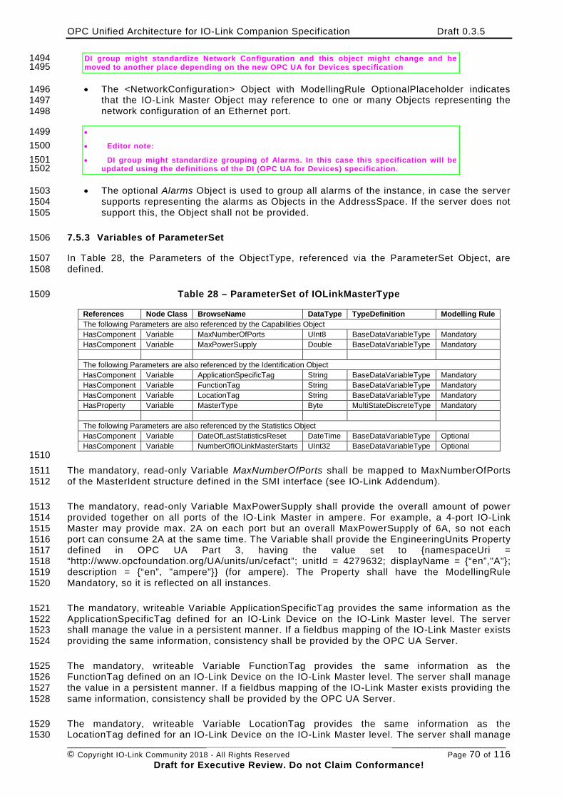
OPC Unified Architecture for IO-Link Companion Specification Draft 0.3.5
________________________________________________________________________________________________________ © Copyright IO-Link Community 2018 - All Rights Reserved Page 70 of 116
Draft for Executive Review. Do not Claim Conformance!
DI group might standardize Network Configuration and this object might change and be 1494 moved to another place depending on the new OPC UA for Devices specification 1495
• The <NetworkConfiguration> Object with ModellingRule OptionalPlaceholder indicates 1496 that the IO-Link Master Object may reference to one or many Objects representing the 1497 network configuration of an Ethernet port. 1498
• 1499 • Editor note: 1500 • DI group might standardize grouping of Alarms. In this case this specification will be 1501
updated using the definitions of the DI (OPC UA for Devices) specification. 1502
• The optional Alarms Object is used to group all alarms of the instance, in case the server 1503 supports representing the alarms as Objects in the AddressSpace. If the server does not 1504 support this, the Object shall not be provided. 1505
7.5.3 Variables of ParameterSet 1506
In Table 28, the Parameters of the ObjectType, referenced via the ParameterSet Object, are 1507 defined. 1508
Table 28 – ParameterSet of IOLinkMasterType 1509
References Node Class BrowseName DataType TypeDefinition Modelling Rule The following Parameters are also referenced by the Capabilities Object HasComponent Variable MaxNumberOfPorts UInt8 BaseDataVariableType Mandatory HasComponent Variable MaxPowerSupply Double BaseDataVariableType Mandatory The following Parameters are also referenced by the Identification Object HasComponent Variable ApplicationSpecificTag String BaseDataVariableType Mandatory HasComponent Variable FunctionTag String BaseDataVariableType Mandatory HasComponent Variable LocationTag String BaseDataVariableType Mandatory HasProperty Variable MasterType Byte MultiStateDiscreteType Mandatory The following Parameters are also referenced by the Statistics Object HasComponent Variable DateOfLastStatisticsReset DateTime BaseDataVariableType Optional HasComponent Variable NumberOfIOLinkMasterStarts UInt32 BaseDataVariableType Optional
1510 The mandatory, read-only Variable MaxNumberOfPorts shall be mapped to MaxNumberOfPorts 1511 of the MasterIdent structure defined in the SMI interface (see IO-Link Addendum). 1512
The mandatory, read-only Variable MaxPowerSupply shall provide the overall amount of power 1513 provided together on all ports of the IO-Link Master in ampere. For example, a 4-port IO-Link 1514 Master may provide max. 2A on each port but an overall MaxPowerSupply of 6A, so not each 1515 port can consume 2A at the same time. The Variable shall provide the EngineeringUnits Property 1516 defined in OPC UA Part 3, having the value set to {namespaceUri = 1517 “http://www.opcfoundation.org/UA/units/un/cefact”; unitId = 4279632; displayName = {“en”,"A"}; 1518 description = {“en”, "ampere"}} (for ampere). The Property shall have the ModellingRule 1519 Mandatory, so it is reflected on all instances. 1520
The mandatory, writeable Variable ApplicationSpecificTag provides the same information as the 1521 ApplicationSpecificTag defined for an IO-Link Device on the IO-Link Master level. The server 1522 shall manage the value in a persistent manner. If a fieldbus mapping of the IO-Link Master exists 1523 providing the same information, consistency shall be provided by the OPC UA Server. 1524
The mandatory, writeable Variable FunctionTag provides the same information as the 1525 FunctionTag defined on an IO-Link Device on the IO-Link Master level. The server shall manage 1526 the value in a persistent manner. If a fieldbus mapping of the IO-Link Master exists providing the 1527 same information, consistency shall be provided by the OPC UA Server. 1528
The mandatory, writeable Variable LocationTag provides the same information as the 1529 LocationTag defined for an IO-Link Device on the IO-Link Master level. The server shall manage 1530
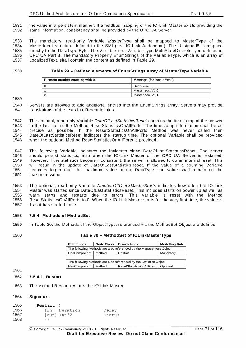
OPC Unified Architecture for IO-Link Companion Specification Draft 0.3.5
________________________________________________________________________________________________________ © Copyright IO-Link Community 2018 - All Rights Reserved Page 71 of 116
Draft for Executive Review. Do not Claim Conformance!
the value in a persistent manner. If a fieldbus mapping of the IO-Link Master exists providing the 1531 same information, consistency shall be provided by the OPC UA Server. 1532
The mandatory, read-only Variable MasterType shall be mapped to MasterType of the 1533 MasterIdent structure defined in the SMI (see IO-Link Addendum). The Unsigned8 is mapped 1534 directly to the DataType Byte. The Variable is of VariableType MultiStateDiscreteType defined in 1535 OPC UA Part 8. The mandatory Property EnumStrings of the VariableType, which is an array of 1536 LocalizedText, shall contain the content as defined in Table 29. 1537
Table 29 – Defined elements of EnumStrings array of MasterType Variable 1538
Element number (starting with 0) Message (for locale “en”)
0 Unspecific 1 Master acc. V1.0 2 Master acc. V1.1
1539 Servers are allowed to add additional entries into the EnumStrings array. Servers may provide 1540 translations of the texts in different locales. 1541
The optional, read-only Variable DateOfLastStatisticsReset contains the timestamp of the answer 1542 to the last call of the Method ResetStatisticsOnAllPorts. The timestamp information shall be as 1543 precise as possible. If the ResetStatisticsOnAllPorts Method was never called then 1544 DateOfLastStatisticsReset indicates the startup time. The optional Variable shall be provided 1545 when the optional Method ResetStatisticsOnAllPorts is provided. 1546
The following Variable indicates the incidents since DateOfLastStatisticsReset. The server 1547 should persist statistics, also when the IO-Link Master or the OPC UA Server is restarted. 1548 However, if the statistics become inconsistent, the server is allowed to do an internal reset. This 1549 will result in the update of DateOfLastStatisticsReset. If the value of a counting Variable 1550 becomes larger than the maximum value of the DataType, the value shall remain on the 1551 maximum value. 1552
The optional, read-only Variable NumberOfIOLinkMasterStarts indicates how often the IO-Link 1553 Master was started since DateOfLastStatisticsReset. This includes starts on power up as well as 1554 warm starts and restarts due to errors. This variable is reset with the Method 1555 ResetStatisticsOnAllPorts to 0. When the IO-Link Master starts for the very first time, the value is 1556 1 as it has started once. 1557
7.5.4 Methods of MethodSet 1558
In Table 30, the Methods of the ObjectType, referenced via the MethodSet Object are defined. 1559
Table 30 – MethodSet of IOLinkMasterType 1560
References Node Class BrowseName Modelling Rule The following Methods are also referenced by the Management Object HasComponent Method Restart Mandatory The following Methods are also referenced by the Statistics Object HasComponent Method ResetStatisticsOnAllPorts Optional
1561 7.5.4.1 Restart 1562
The Method Restart restarts the IO-Link Master. 1563
Signature 1564
Restart ( 1565 [in] Duration Delay, 1566 [out] Int32 Status 1567 ); 1568
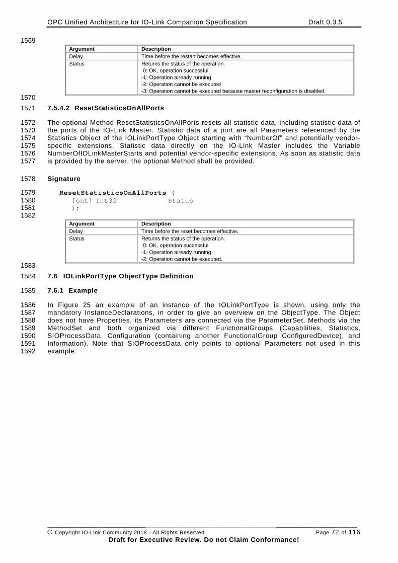
OPC Unified Architecture for IO-Link Companion Specification Draft 0.3.5
________________________________________________________________________________________________________ © Copyright IO-Link Community 2018 - All Rights Reserved Page 72 of 116
Draft for Executive Review. Do not Claim Conformance!
1569 Argument Description Delay Time before the restart becomes effective. Status Returns the status of the operation.
0: OK, operation successful -1: Operation already running -2: Operation cannot be executed -3: Operation cannot be executed because master reconfiguration is disabled.
1570 7.5.4.2 ResetStatisticsOnAllPorts 1571
The optional Method ResetStatisticsOnAllPorts resets all statistic data, including statistic data of 1572 the ports of the IO-Link Master. Statistic data of a port are all Parameters referenced by the 1573 Statistics Object of the IOLinkPortType Object starting with “NumberOf” and potentially vendor-1574 specific extensions. Statistic data directly on the IO-Link Master includes the Variable 1575 NumberOfIOLinkMasterStarts and potential vendor-specific extensions. As soon as statistic data 1576 is provided by the server, the optional Method shall be provided. 1577
Signature 1578
ResetStatisticsOnAllPorts ( 1579 [out] Int32 Status 1580 ); 1581 1582
Argument Description Delay Time before the reset becomes effective. Status Returns the status of the operation.
0: OK, operation successful -1: Operation already running -2: Operation cannot be executed.
1583 7.6 IOLinkPortType ObjectType Definition 1584
7.6.1 Example 1585
In Figure 25 an example of an instance of the IOLinkPortType is shown, using only the 1586 mandatory InstanceDeclarations, in order to give an overview on the ObjectType. The Object 1587 does not have Properties, its Parameters are connected via the ParameterSet, Methods via the 1588 MethodSet and both organized via different FunctionalGroups (Capabilities, Statistics, 1589 SIOProcessData, Configuration (containing another FunctionalGroup ConfiguredDevice), and 1590 Information). Note that SIOProcessData only points to optional Parameters not used in this 1591 example. 1592
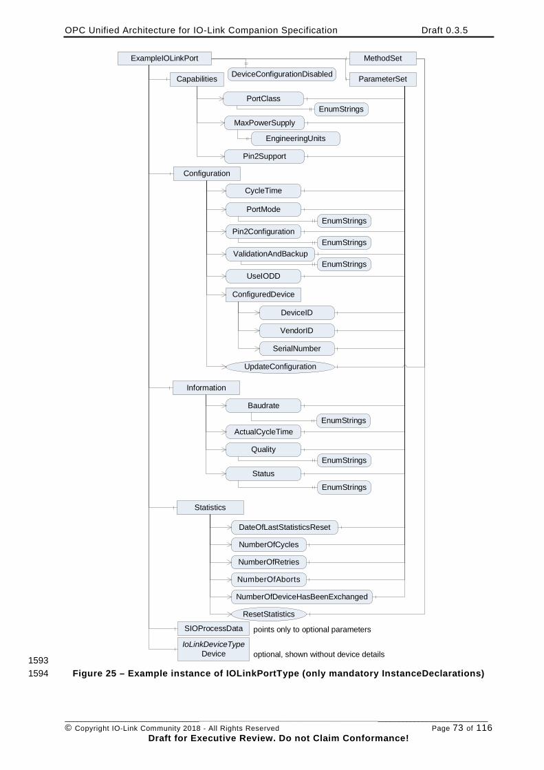
OPC Unified Architecture for IO-Link Companion Specification Draft 0.3.5
________________________________________________________________________________________________________ © Copyright IO-Link Community 2018 - All Rights Reserved Page 73 of 116
Draft for Executive Review. Do not Claim Conformance!
ExampleIOLinkPort
Capabilities
PortClass
MaxPowerSupply
Pin2Support
PortMode
ValidationAndBackup
Information
CycleTime
Baudrate
ResetStatistics
IoLinkDeviceTypeDevice
ParameterSet
MethodSet
Pin2Configuration
Statistics
DateOfLastStatisticsReset
NumberOfCycles
SIOProcessData
optional, shown without device details
Configuration
ConfiguredDevice
VendorID
SerialNumber
DeviceID
ActualCycleTime
NumberOfRetries
NumberOfAborts
NumberOfDeviceHasBeenExchanged
Status
UpdateConfiguration
points only to optional parameters
EnumStrings
EngineeringUnits
EnumStrings
EnumStrings
EnumStrings
EnumStrings
DeviceConfigurationDisabled
UseIODD
EnumStrings
QualityEnumStrings
1593 Figure 25 – Example instance of IOLinkPortType (only mandatory InstanceDeclarations) 1594
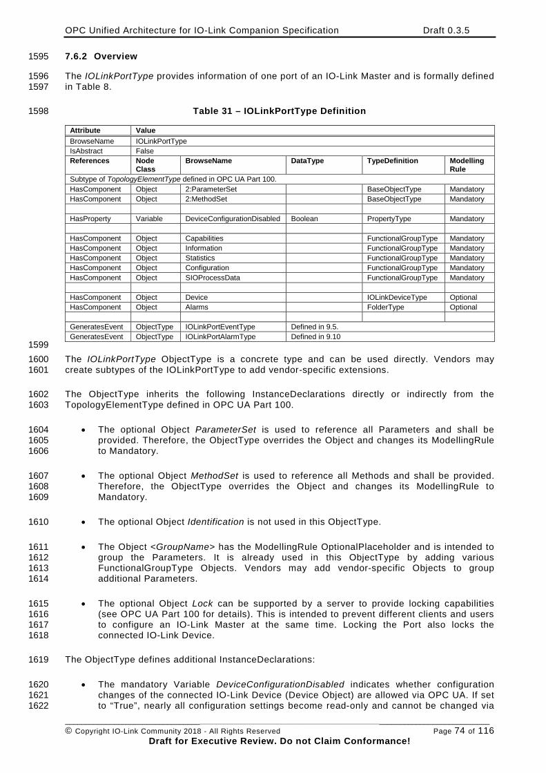
OPC Unified Architecture for IO-Link Companion Specification Draft 0.3.5
________________________________________________________________________________________________________ © Copyright IO-Link Community 2018 - All Rights Reserved Page 74 of 116
Draft for Executive Review. Do not Claim Conformance!
7.6.2 Overview 1595
The IOLinkPortType provides information of one port of an IO-Link Master and is formally defined 1596 in Table 8. 1597
Table 31 – IOLinkPortType Definition 1598
Attribute Value BrowseName IOLinkPortType IsAbstract False References Node
Class BrowseName DataType TypeDefinition Modelling
Rule Subtype of TopologyElementType defined in OPC UA Part 100. HasComponent Object 2:ParameterSet BaseObjectType Mandatory HasComponent Object 2:MethodSet BaseObjectType Mandatory HasProperty Variable DeviceConfigurationDisabled Boolean PropertyType Mandatory HasComponent Object Capabilities FunctionalGroupType Mandatory HasComponent Object Information FunctionalGroupType Mandatory HasComponent Object Statistics FunctionalGroupType Mandatory HasComponent Object Configuration FunctionalGroupType Mandatory HasComponent Object SIOProcessData FunctionalGroupType Mandatory HasComponent Object Device IOLinkDeviceType Optional HasComponent Object Alarms FolderType Optional GeneratesEvent ObjectType IOLinkPortEventType Defined in 9.5. GeneratesEvent ObjectType IOLinkPortAlarmType Defined in 9.10
1599 The IOLinkPortType ObjectType is a concrete type and can be used directly. Vendors may 1600 create subtypes of the IOLinkPortType to add vendor-specific extensions. 1601
The ObjectType inherits the following InstanceDeclarations directly or indirectly from the 1602 TopologyElementType defined in OPC UA Part 100. 1603
• The optional Object ParameterSet is used to reference all Parameters and shall be 1604 provided. Therefore, the ObjectType overrides the Object and changes its ModellingRule 1605 to Mandatory. 1606
• The optional Object MethodSet is used to reference all Methods and shall be provided. 1607 Therefore, the ObjectType overrides the Object and changes its ModellingRule to 1608 Mandatory. 1609
• The optional Object Identification is not used in this ObjectType. 1610
• The Object <GroupName> has the ModellingRule OptionalPlaceholder and is intended to 1611 group the Parameters. It is already used in this ObjectType by adding various 1612 FunctionalGroupType Objects. Vendors may add vendor-specific Objects to group 1613 additional Parameters. 1614
• The optional Object Lock can be supported by a server to provide locking capabilities 1615 (see OPC UA Part 100 for details). This is intended to prevent different clients and users 1616 to configure an IO-Link Master at the same time. Locking the Port also locks the 1617 connected IO-Link Device. 1618
The ObjectType defines additional InstanceDeclarations: 1619
• The mandatory Variable DeviceConfigurationDisabled indicates whether configuration 1620 changes of the connected IO-Link Device (Device Object) are allowed via OPC UA. If set 1621 to “True”, nearly all configuration settings become read-only and cannot be changed via 1622
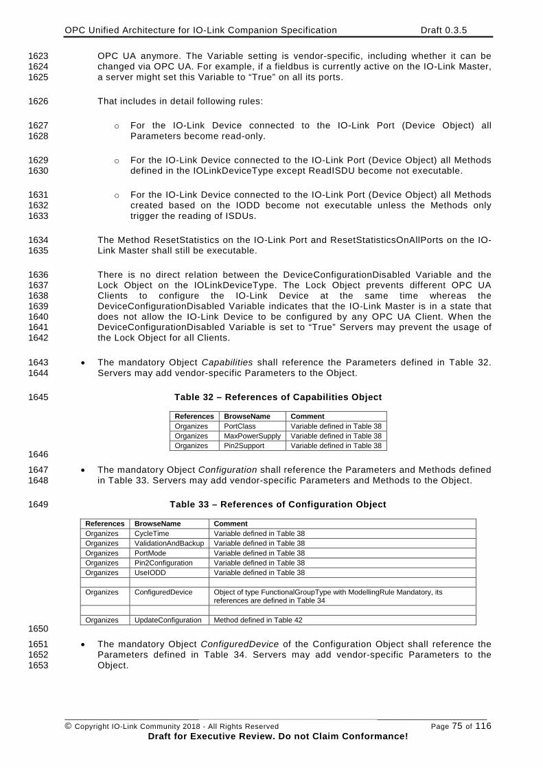
OPC Unified Architecture for IO-Link Companion Specification Draft 0.3.5
________________________________________________________________________________________________________ © Copyright IO-Link Community 2018 - All Rights Reserved Page 75 of 116
Draft for Executive Review. Do not Claim Conformance!
OPC UA anymore. The Variable setting is vendor-specific, including whether it can be 1623 changed via OPC UA. For example, if a fieldbus is currently active on the IO-Link Master, 1624 a server might set this Variable to “True” on all its ports. 1625
That includes in detail following rules: 1626
o For the IO-Link Device connected to the IO-Link Port (Device Object) all 1627 Parameters become read-only. 1628
o For the IO-Link Device connected to the IO-Link Port (Device Object) all Methods 1629 defined in the IOLinkDeviceType except ReadISDU become not executable. 1630
o For the IO-Link Device connected to the IO-Link Port (Device Object) all Methods 1631 created based on the IODD become not executable unless the Methods only 1632 trigger the reading of ISDUs. 1633
The Method ResetStatistics on the IO-Link Port and ResetStatisticsOnAllPorts on the IO-1634 Link Master shall still be executable. 1635
There is no direct relation between the DeviceConfigurationDisabled Variable and the 1636 Lock Object on the IOLinkDeviceType. The Lock Object prevents different OPC UA 1637 Clients to configure the IO-Link Device at the same time whereas the 1638 DeviceConfigurationDisabled Variable indicates that the IO-Link Master is in a state that 1639 does not allow the IO-Link Device to be configured by any OPC UA Client. When the 1640 DeviceConfigurationDisabled Variable is set to “True” Servers may prevent the usage of 1641 the Lock Object for all Clients. 1642
• The mandatory Object Capabilities shall reference the Parameters defined in Table 32. 1643 Servers may add vendor-specific Parameters to the Object. 1644
Table 32 – References of Capabilities Object 1645
References BrowseName Comment Organizes PortClass Variable defined in Table 38 Organizes MaxPowerSupply Variable defined in Table 38 Organizes Pin2Support Variable defined in Table 38
1646 • The mandatory Object Configuration shall reference the Parameters and Methods defined 1647
in Table 33. Servers may add vendor-specific Parameters and Methods to the Object. 1648
Table 33 – References of Configuration Object 1649
References BrowseName Comment Organizes CycleTime Variable defined in Table 38 Organizes ValidationAndBackup Variable defined in Table 38 Organizes PortMode Variable defined in Table 38 Organizes Pin2Configuration Variable defined in Table 38 Organizes UseIODD Variable defined in Table 38 Organizes ConfiguredDevice Object of type FunctionalGroupType with ModellingRule Mandatory, its
references are defined in Table 34 Organizes UpdateConfiguration Method defined in Table 42
1650 • The mandatory Object ConfiguredDevice of the Configuration Object shall reference the 1651
Parameters defined in Table 34. Servers may add vendor-specific Parameters to the 1652 Object. 1653
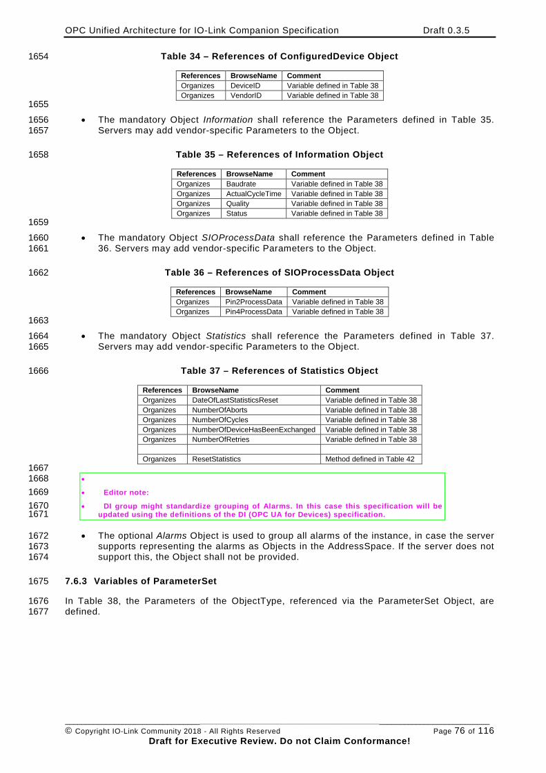
OPC Unified Architecture for IO-Link Companion Specification Draft 0.3.5
________________________________________________________________________________________________________ © Copyright IO-Link Community 2018 - All Rights Reserved Page 76 of 116
Draft for Executive Review. Do not Claim Conformance!
Table 34 – References of ConfiguredDevice Object 1654
References BrowseName Comment Organizes DeviceID Variable defined in Table 38 Organizes VendorID Variable defined in Table 38
1655 • The mandatory Object Information shall reference the Parameters defined in Table 35. 1656
Servers may add vendor-specific Parameters to the Object. 1657
Table 35 – References of Information Object 1658
References BrowseName Comment Organizes Baudrate Variable defined in Table 38 Organizes ActualCycleTime Variable defined in Table 38 Organizes Quality Variable defined in Table 38 Organizes Status Variable defined in Table 38
1659 • The mandatory Object SIOProcessData shall reference the Parameters defined in Table 1660
36. Servers may add vendor-specific Parameters to the Object. 1661
Table 36 – References of SIOProcessData Object 1662
References BrowseName Comment Organizes Pin2ProcessData Variable defined in Table 38 Organizes Pin4ProcessData Variable defined in Table 38
1663 • The mandatory Object Statistics shall reference the Parameters defined in Table 37. 1664
Servers may add vendor-specific Parameters to the Object. 1665
Table 37 – References of Statistics Object 1666
References BrowseName Comment Organizes DateOfLastStatisticsReset Variable defined in Table 38 Organizes NumberOfAborts Variable defined in Table 38 Organizes NumberOfCycles Variable defined in Table 38 Organizes NumberOfDeviceHasBeenExchanged Variable defined in Table 38 Organizes NumberOfRetries Variable defined in Table 38 Organizes ResetStatistics Method defined in Table 42
1667 • 1668 • Editor note: 1669 • DI group might standardize grouping of Alarms. In this case this specification will be 1670
updated using the definitions of the DI (OPC UA for Devices) specification. 1671
• The optional Alarms Object is used to group all alarms of the instance, in case the server 1672 supports representing the alarms as Objects in the AddressSpace. If the server does not 1673 support this, the Object shall not be provided. 1674
7.6.3 Variables of ParameterSet 1675
In Table 38, the Parameters of the ObjectType, referenced via the ParameterSet Object, are 1676 defined. 1677
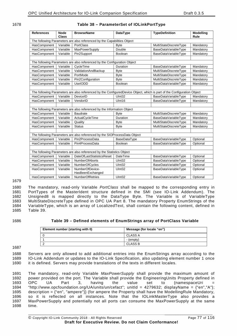
OPC Unified Architecture for IO-Link Companion Specification Draft 0.3.5
________________________________________________________________________________________________________ © Copyright IO-Link Community 2018 - All Rights Reserved Page 77 of 116
Draft for Executive Review. Do not Claim Conformance!
Table 38 – ParameterSet of IOLinkPortType 1678
References Node Class
BrowseName DataType TypeDefinition Modelling Rule
The following Parameters are also referenced by the Capabilities Object HasComponent Variable PortClass Byte MultiStateDiscreteType Mandatory HasComponent Variable MaxPowerSupply Double BaseDataVariableType Mandatory HasComponent Variable Pin2Support Boolean BaseDataVariableType Mandatory The following Parameters are also referenced by the Configuration Object HasComponent Variable CycleTime Duration BaseDataVariableType Mandatory HasComponent Variable ValidationAndBackup Byte MultiStateDiscreteType Mandatory HasComponent Variable PortMode Byte MultiStateDiscreteType Mandatory HasComponent Variable Pin2Configuration Byte MultiStateDiscreteType Mandatory HasComponent Variable UseIODD Boolean BaseDataVariableType Mandatory The following Parameters are also referenced by the ConfiguredDevice Object, which is part of the Configuration Object HasComponent Variable DeviceID UInt32 BaseDataVariableType Mandatory HasComponent Variable VendorID UInt16 BaseDataVariableType Mandatory The following Parameters are also referenced by the Information Object HasComponent Variable Baudrate Byte MultiStateDiscreteType Mandatory HasComponent Variable ActualCycleTime Duration BaseDataVariableType Mandatory HasComponent Variable Quality Byte MultiStateDiscreteType Mandatory HasComponent Variable Status Byte MultiStateDiscreteType Mandatory The following Parameters are also referenced by the SIOProcessData Object HasComponent Variable Pin2ProcessData BaseDataType BaseDataVariableType Optional HasComponent Variable Pin4ProcessData Boolean BaseDataVariableType Optional The following Parameters are also referenced by the Statistics Object HasComponent Variable DateOfLastStatisticsReset DateTime BaseDataVariableType Optional HasComponent Variable NumberOfAborts UInt32 BaseDataVariableType Optional HasComponent Variable NumberOfCycles UInt32 BaseDataVariableType Optional HasComponent Variable NumberOfDevice-
HasBeenExchanged UInt32 BaseDataVariableType Optional
HasComponent Variable NumberOfRetries UInt32 BaseDataVariableType Optional 1679 The mandatory, read-only Variable PortClass shall be mapped to the corresponding entry in 1680 PortTypes of the MasterIdent structure defined in the SMI (see IO-Link Addendum). The 1681 Unsigned8 is mapped directly to the DataType Byte. The Variable is of VariableType 1682 MultiStateDiscreteType defined in OPC UA Part 8. The mandatory Property EnumStrings of the 1683 VariableType, which is an array of LocalizedText, shall contain the following content, defined in 1684 Table 39. 1685
Table 39 – Defined elements of EnumStrings array of PortClass Variable 1686
Element number (starting with 0) Message (for locale “en”)
0 CLASS A 1 - (empty) 2 CLASS B
1687 Servers are only allowed to add additional entries into the EnumStrings array according to the 1688 IO-Link Addendum or updates to the IO-Link Specification, also updating element number 1 once 1689 it is defined. Servers may provide translations of the texts in different locales. 1690
The mandatory, read-only Variable MaxPowerSupply shall provide the maximum amount of 1691 power provided on the port. The Variable shall provide the EngineeringUnits Property defined in 1692 OPC UA Part 3, having the value set to {namespaceUri = 1693 “http://www.opcfoundation.org/UA/units/un/cefact”; unitId = 4279632; displayName = {“en”,"A"}; 1694 description = {“en”, "ampere"}} (for ampere the Property shall have the ModellingRule Mandatory, 1695 so it is reflected on all instances. Note that the IOLinkMasterType also provides a 1696 MaxPowerSupply and potentially not all ports can consume the MaxPowerSupply at the same 1697 time. 1698
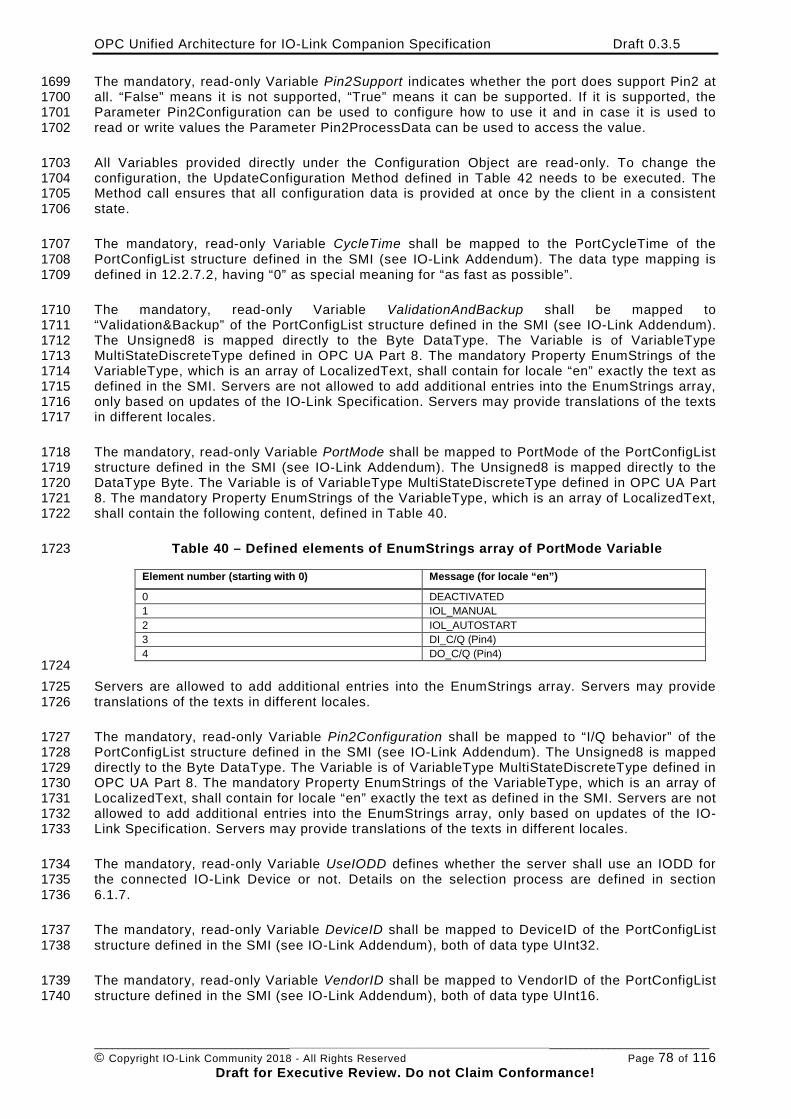
OPC Unified Architecture for IO-Link Companion Specification Draft 0.3.5
________________________________________________________________________________________________________ © Copyright IO-Link Community 2018 - All Rights Reserved Page 78 of 116
Draft for Executive Review. Do not Claim Conformance!
The mandatory, read-only Variable Pin2Support indicates whether the port does support Pin2 at 1699 all. “False” means it is not supported, “True” means it can be supported. If it is supported, the 1700 Parameter Pin2Configuration can be used to configure how to use it and in case it is used to 1701 read or write values the Parameter Pin2ProcessData can be used to access the value. 1702
All Variables provided directly under the Configuration Object are read-only. To change the 1703 configuration, the UpdateConfiguration Method defined in Table 42 needs to be executed. The 1704 Method call ensures that all configuration data is provided at once by the client in a consistent 1705 state. 1706
The mandatory, read-only Variable CycleTime shall be mapped to the PortCycleTime of the 1707 PortConfigList structure defined in the SMI (see IO-Link Addendum). The data type mapping is 1708 defined in 12.2.7.2, having “0” as special meaning for “as fast as possible”. 1709
The mandatory, read-only Variable ValidationAndBackup shall be mapped to 1710 “Validation&Backup” of the PortConfigList structure defined in the SMI (see IO-Link Addendum). 1711 The Unsigned8 is mapped directly to the Byte DataType. The Variable is of VariableType 1712 MultiStateDiscreteType defined in OPC UA Part 8. The mandatory Property EnumStrings of the 1713 VariableType, which is an array of LocalizedText, shall contain for locale “en” exactly the text as 1714 defined in the SMI. Servers are not allowed to add additional entries into the EnumStrings array, 1715 only based on updates of the IO-Link Specification. Servers may provide translations of the texts 1716 in different locales. 1717
The mandatory, read-only Variable PortMode shall be mapped to PortMode of the PortConfigList 1718 structure defined in the SMI (see IO-Link Addendum). The Unsigned8 is mapped directly to the 1719 DataType Byte. The Variable is of VariableType MultiStateDiscreteType defined in OPC UA Part 1720 8. The mandatory Property EnumStrings of the VariableType, which is an array of LocalizedText, 1721 shall contain the following content, defined in Table 40. 1722
Table 40 – Defined elements of EnumStrings array of PortMode Variable 1723
Element number (starting with 0) Message (for locale “en”)
0 DEACTIVATED 1 IOL_MANUAL 2 IOL_AUTOSTART 3 DI_C/Q (Pin4) 4 DO_C/Q (Pin4)
1724 Servers are allowed to add additional entries into the EnumStrings array. Servers may provide 1725 translations of the texts in different locales. 1726
The mandatory, read-only Variable Pin2Configuration shall be mapped to “I/Q behavior” of the 1727 PortConfigList structure defined in the SMI (see IO-Link Addendum). The Unsigned8 is mapped 1728 directly to the Byte DataType. The Variable is of VariableType MultiStateDiscreteType defined in 1729 OPC UA Part 8. The mandatory Property EnumStrings of the VariableType, which is an array of 1730 LocalizedText, shall contain for locale “en” exactly the text as defined in the SMI. Servers are not 1731 allowed to add additional entries into the EnumStrings array, only based on updates of the IO-1732 Link Specification. Servers may provide translations of the texts in different locales. 1733
The mandatory, read-only Variable UseIODD defines whether the server shall use an IODD for 1734 the connected IO-Link Device or not. Details on the selection process are defined in section 1735 6.1.7. 1736
The mandatory, read-only Variable DeviceID shall be mapped to DeviceID of the PortConfigList 1737 structure defined in the SMI (see IO-Link Addendum), both of data type UInt32. 1738
The mandatory, read-only Variable VendorID shall be mapped to VendorID of the PortConfigList 1739 structure defined in the SMI (see IO-Link Addendum), both of data type UInt16. 1740

OPC Unified Architecture for IO-Link Companion Specification Draft 0.3.5
________________________________________________________________________________________________________ © Copyright IO-Link Community 2018 - All Rights Reserved Page 79 of 116
Draft for Executive Review. Do not Claim Conformance!
The mandatory, read-only Variable Baudrate shall be mapped to TransmissionRate of the 1741 PortStatusList structure defined in the SMI (see IO-Link Addendum). The DataType (Byte) shall 1742 be mapped to the UInteger8. The EnumStrings Property of the MultiStateDiscreteType shall be 1743 used according to the values defined for the TransmissionRate in IO-Link Addendum, and shall 1744 at least provide all valid Values supported by the IO-Link Master. 1745
The mandatory, read-only Variable ActualCycleTime shall be mapped to the MasterCycleTime of 1746 the PortStatusList structure defined in the SMI (see IO-Link Addendum). The data type mapping 1747 is defined in 12.2.7.2. 1748
The mandatory, read-only Variable Quality shall be mapped to “PortQualityInfo” of the 1749 PortStatusList structure defined in the SMI (see IO-Link Addendum). The Unsigned8 is mapped 1750 directly to the Byte DataType. The Variable is of VariableType MultiStateDiscreteType defined in 1751 OPC UA Part 8. The mandatory Property EnumStrings of the VariableType, which is an array of 1752 LocalizedText, shall contain for locale “en” exactly the text as defined in the SMI. Servers are not 1753 allowed to add additional entries into the EnumStrings array, only based on updates of the IO-1754 Link Specification. Servers may provide translations of the texts in different locales. 1755
The mandatory, read-only Variable Status shall be mapped to PortStatusInfo of the 1756 PortStatusList structure defined in the SMI (see IO-Link Addendum). The Unsigned8 is mapped 1757 directly to the Byte DataType. The Variable is of VariableType MultiStateDiscreteType defined in 1758 OPC UA Part 8. The mandatory Property EnumStrings of the VariableType, which is an array of 1759 LocalizedText, shall contain the following content, defined in Table 41. 1760
Table 41 – Defined elements of EnumStrings array of Status Variable 1761
Element number (starting with 0) Text (for locale “en”)
0 NO_DEVICE 1 DEACTIVATED 2 INCORRECT_DEVICE 3 PREOPERATE 4 OPERATE 5 DI_C/Q (Pin4) 6 DO_C/Q (Pin4) 7-253 - (empty) 254 PORT_FAULT 255 NOT_AVAILABLE
1762 Servers may update the values for 7-253 when the IO-Link Specification gets updated. Servers 1763 may provide translations of the texts in different locales. 1764
The date since connection is running or not running is shown in SourceTimestamp of the Status. 1765 Because of this a server that supports persistent statistics shall not change the 1766 SourceTimestamp of Status on restart of the IO-Link Master or OPC UA Server. 1767
The optional Variable Pin2ProcessData provides the process data value of the Pin2. The 1768 DataType is vendor-specific. 1769
The optional Variable Pin4ProcessData provides the process data value of the Pin4 in case the 1770 IO-Link Port is configured as SIO. The Variable shall only be provided when the PortMode is set 1771 to “DI_C/Q (Pin4)” or “DO_C/Q (Pin4)”. 1772
The optional, read-only Variable DateOfLastStatisticsReset contains the timestamp of the answer 1773 to the last call of the Method ResetStatistics, respectively ResetStatisticsOnAllPorts defined on 1774 the IOLinkMasterType. The timestamp information shall be as precise as possible. If the reset 1775 Methods were never called then DateOfLastStatisticsReset indicates the startup time. The 1776 optional Variable shall be provided when the optional Method ResetStatistics is provided. 1777
The following Variables indicate the incidents since DateOfLastStatisticsReset. The server 1778 should persist statistics, also when the IO-Link Master or the OPC UA Server is restarted. 1779
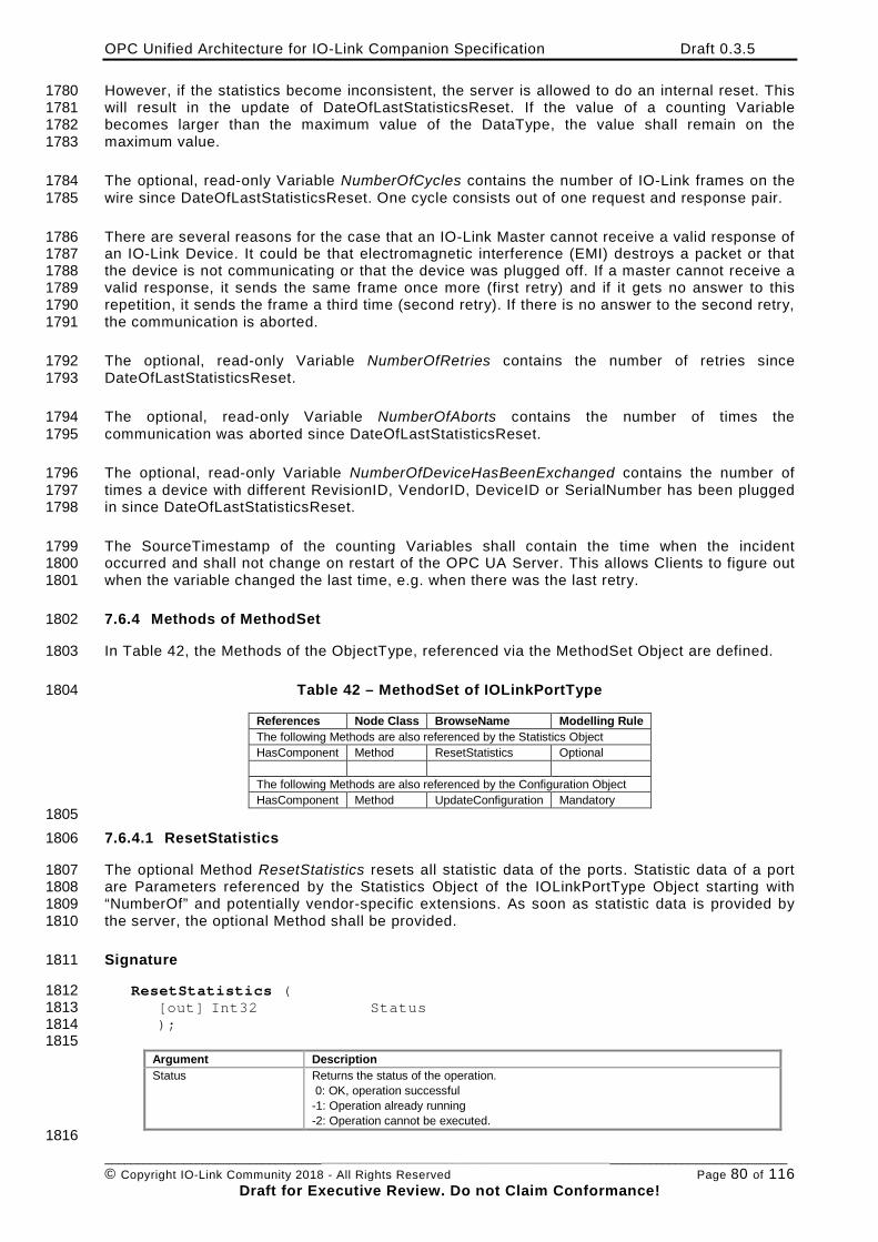
OPC Unified Architecture for IO-Link Companion Specification Draft 0.3.5
________________________________________________________________________________________________________ © Copyright IO-Link Community 2018 - All Rights Reserved Page 80 of 116
Draft for Executive Review. Do not Claim Conformance!
However, if the statistics become inconsistent, the server is allowed to do an internal reset. This 1780 will result in the update of DateOfLastStatisticsReset. If the value of a counting Variable 1781 becomes larger than the maximum value of the DataType, the value shall remain on the 1782 maximum value. 1783
The optional, read-only Variable NumberOfCycles contains the number of IO-Link frames on the 1784 wire since DateOfLastStatisticsReset. One cycle consists out of one request and response pair. 1785
There are several reasons for the case that an IO-Link Master cannot receive a valid response of 1786 an IO-Link Device. It could be that electromagnetic interference (EMI) destroys a packet or that 1787 the device is not communicating or that the device was plugged off. If a master cannot receive a 1788 valid response, it sends the same frame once more (first retry) and if it gets no answer to this 1789 repetition, it sends the frame a third time (second retry). If there is no answer to the second retry, 1790 the communication is aborted. 1791
The optional, read-only Variable NumberOfRetries contains the number of retries since 1792 DateOfLastStatisticsReset. 1793
The optional, read-only Variable NumberOfAborts contains the number of times the 1794 communication was aborted since DateOfLastStatisticsReset. 1795
The optional, read-only Variable NumberOfDeviceHasBeenExchanged contains the number of 1796 times a device with different RevisionID, VendorID, DeviceID or SerialNumber has been plugged 1797 in since DateOfLastStatisticsReset. 1798
The SourceTimestamp of the counting Variables shall contain the time when the incident 1799 occurred and shall not change on restart of the OPC UA Server. This allows Clients to figure out 1800 when the variable changed the last time, e.g. when there was the last retry. 1801
7.6.4 Methods of MethodSet 1802
In Table 42, the Methods of the ObjectType, referenced via the MethodSet Object are defined. 1803
Table 42 – MethodSet of IOLinkPortType 1804
References Node Class BrowseName Modelling Rule The following Methods are also referenced by the Statistics Object HasComponent Method ResetStatistics Optional The following Methods are also referenced by the Configuration Object HasComponent Method UpdateConfiguration Mandatory
1805 7.6.4.1 ResetStatistics 1806
The optional Method ResetStatistics resets all statistic data of the ports. Statistic data of a port 1807 are Parameters referenced by the Statistics Object of the IOLinkPortType Object starting with 1808 “NumberOf” and potentially vendor-specific extensions. As soon as statistic data is provided by 1809 the server, the optional Method shall be provided. 1810
Signature 1811
ResetStatistics ( 1812 [out] Int32 Status 1813 ); 1814 1815
Argument Description Status Returns the status of the operation.
0: OK, operation successful -1: Operation already running -2: Operation cannot be executed.
1816
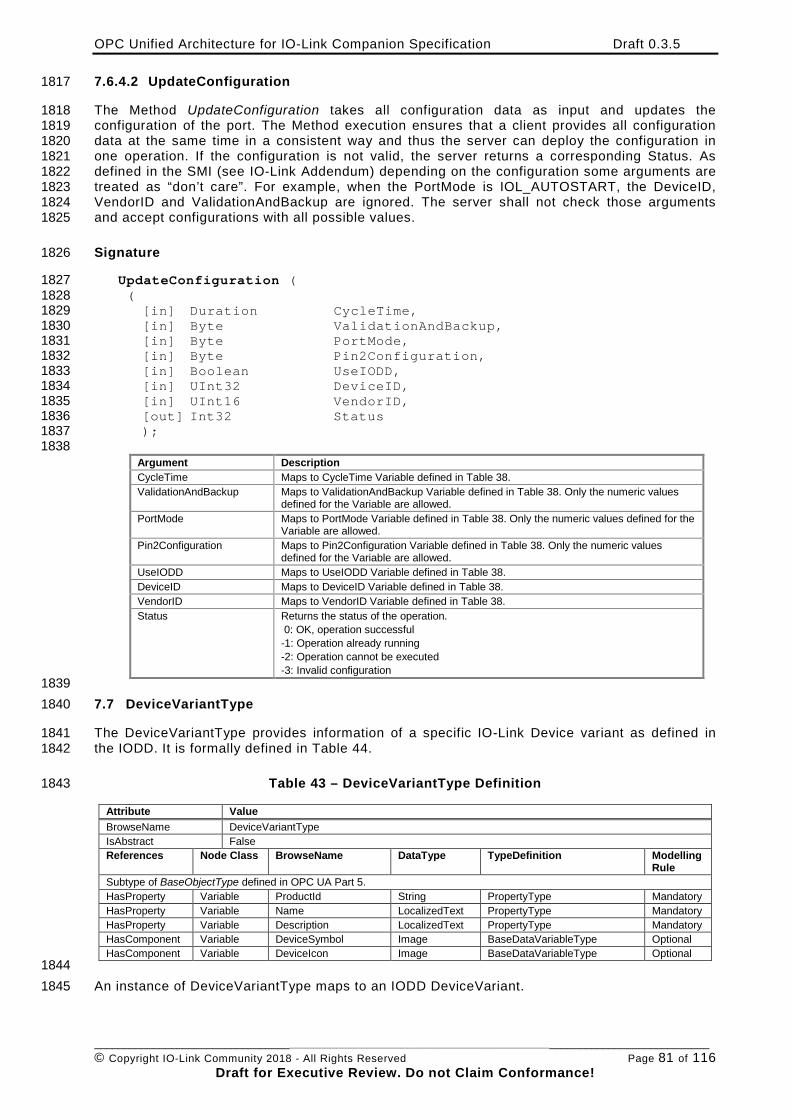
OPC Unified Architecture for IO-Link Companion Specification Draft 0.3.5
________________________________________________________________________________________________________ © Copyright IO-Link Community 2018 - All Rights Reserved Page 81 of 116
Draft for Executive Review. Do not Claim Conformance!
7.6.4.2 UpdateConfiguration 1817
The Method UpdateConfiguration takes all configuration data as input and updates the 1818 configuration of the port. The Method execution ensures that a client provides all configuration 1819 data at the same time in a consistent way and thus the server can deploy the configuration in 1820 one operation. If the configuration is not valid, the server returns a corresponding Status. As 1821 defined in the SMI (see IO-Link Addendum) depending on the configuration some arguments are 1822 treated as “don’t care”. For example, when the PortMode is IOL_AUTOSTART, the DeviceID, 1823 VendorID and ValidationAndBackup are ignored. The server shall not check those arguments 1824 and accept configurations with all possible values. 1825
Signature 1826
UpdateConfiguration ( 1827 ( 1828 [in] Duration CycleTime, 1829 [in] Byte ValidationAndBackup, 1830 [in] Byte PortMode, 1831 [in] Byte Pin2Configuration, 1832 [in] Boolean UseIODD, 1833 [in] UInt32 DeviceID, 1834 [in] UInt16 VendorID, 1835 [out] Int32 Status 1836 ); 1837 1838
Argument Description CycleTime Maps to CycleTime Variable defined in Table 38. ValidationAndBackup Maps to ValidationAndBackup Variable defined in Table 38. Only the numeric values
defined for the Variable are allowed. PortMode Maps to PortMode Variable defined in Table 38. Only the numeric values defined for the
Variable are allowed. Pin2Configuration Maps to Pin2Configuration Variable defined in Table 38. Only the numeric values
defined for the Variable are allowed. UseIODD Maps to UseIODD Variable defined in Table 38. DeviceID Maps to DeviceID Variable defined in Table 38. VendorID Maps to VendorID Variable defined in Table 38. Status Returns the status of the operation.
0: OK, operation successful -1: Operation already running -2: Operation cannot be executed -3: Invalid configuration
1839 7.7 DeviceVariantType 1840
The DeviceVariantType provides information of a specific IO-Link Device variant as defined in 1841 the IODD. It is formally defined in Table 44. 1842
Table 43 – DeviceVariantType Definition 1843
Attribute Value BrowseName DeviceVariantType IsAbstract False References Node Class BrowseName DataType TypeDefinition Modelling
Rule Subtype of BaseObjectType defined in OPC UA Part 5. HasProperty Variable ProductId String PropertyType Mandatory HasProperty Variable Name LocalizedText PropertyType Mandatory HasProperty Variable Description LocalizedText PropertyType Mandatory HasComponent Variable DeviceSymbol Image BaseDataVariableType Optional HasComponent Variable DeviceIcon Image BaseDataVariableType Optional
1844 An instance of DeviceVariantType maps to an IODD DeviceVariant. 1845
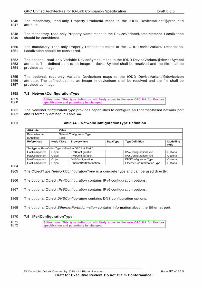
OPC Unified Architecture for IO-Link Companion Specification Draft 0.3.5
________________________________________________________________________________________________________ © Copyright IO-Link Community 2018 - All Rights Reserved Page 82 of 116
Draft for Executive Review. Do not Claim Conformance!
The mandatory, read-only Property ProductId maps to the IODD DeviceVariant/@productId 1846 attribute. 1847
The mandatory, read-only Property Name maps to the DeviceVariant/Name element. Localization 1848 should be considered. 1849
The mandatory, read-only Property Description maps to the IODD DeviceVariant/ Description. 1850 Localization should be considered. 1851
The optional, read-only Variable DeviceSymbol maps to the IODD DeviceVariant/@deviceSymbol 1852 attribute. The defined path to an image in deviceSymbol shall be resolved and the file shall be 1853 provided as Image. 1854
The optional, read-only Variable DeviceIcon maps to the IODD DeviceVariant/@deviceIcon 1855 attribute. The defined path to an image in deviceIcon shall be resolved and the file shall be 1856 provided as Image. 1857
7.8 NetworkConfigurationType 1858 Editor note: This type definition will likely move to the new OPC UA for Devices 1859 specification and potentially be changed 1860
The NetworkConfigurationType provides capabilities to configure an Ethernet-based network port 1861 and is formally defined in Table 44. 1862
Table 44 – NetworkConfigurationType Definition 1863
Attribute Value BrowseName NetworkConfigurationType IsAbstract False References Node Class BrowseName DataType TypeDefinition Modelling
Rule Subtype of BaseObjectType defined in OPC UA Part 5. HasComponent Object IPv4Configuration IPv4ConfigurationType Optional HasComponent Object IPv6Configuration IPv6ConfigurationType Optional HasComponent Object DNSConfiguration DNSConfigurationType Optional HasComponent Object EthernetPortInformation EthernetPortInformationType Optional
1864 The ObjectType NetworkConfigurationType is a concrete type and can be used directly. 1865
The optional Object IPv4Configuration contains IPv4 configuration options. 1866
The optional Object IPv6Configuration contains IPv6 configuration options. 1867
The optional Object DNSConfiguration contains DNS configuration options. 1868
The optional Object EthernetPortInformation contains information about the Ethernet port. 1869
7.9 IPv4ConfigurationType 1870 Editor note: This type definition will likely move to the new OPC UA for Devices 1871 specification and potentially be changed 1872
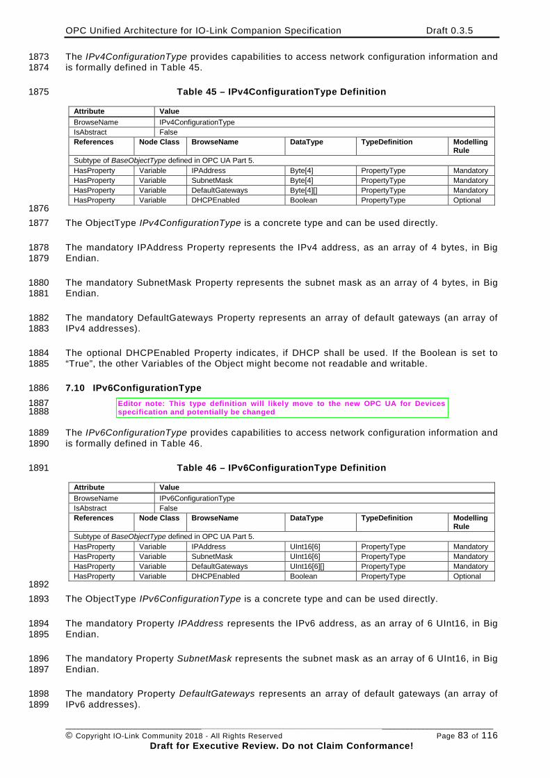
OPC Unified Architecture for IO-Link Companion Specification Draft 0.3.5
________________________________________________________________________________________________________ © Copyright IO-Link Community 2018 - All Rights Reserved Page 83 of 116
Draft for Executive Review. Do not Claim Conformance!
The IPv4ConfigurationType provides capabilities to access network configuration information and 1873 is formally defined in Table 45. 1874
Table 45 – IPv4ConfigurationType Definition 1875
Attribute Value BrowseName IPv4ConfigurationType IsAbstract False References Node Class BrowseName DataType TypeDefinition Modelling
Rule Subtype of BaseObjectType defined in OPC UA Part 5. HasProperty Variable IPAddress Byte[4] PropertyType Mandatory HasProperty Variable SubnetMask Byte[4] PropertyType Mandatory HasProperty Variable DefaultGateways Byte[4][] PropertyType Mandatory HasProperty Variable DHCPEnabled Boolean PropertyType Optional
1876 The ObjectType IPv4ConfigurationType is a concrete type and can be used directly. 1877
The mandatory IPAddress Property represents the IPv4 address, as an array of 4 bytes, in Big 1878 Endian. 1879
The mandatory SubnetMask Property represents the subnet mask as an array of 4 bytes, in Big 1880 Endian. 1881
The mandatory DefaultGateways Property represents an array of default gateways (an array of 1882 IPv4 addresses). 1883
The optional DHCPEnabled Property indicates, if DHCP shall be used. If the Boolean is set to 1884 “True”, the other Variables of the Object might become not readable and writable. 1885
7.10 IPv6ConfigurationType 1886 Editor note: This type definition will likely move to the new OPC UA for Devices 1887 specification and potentially be changed 1888
The IPv6ConfigurationType provides capabilities to access network configuration information and 1889 is formally defined in Table 46. 1890
Table 46 – IPv6ConfigurationType Definition 1891
Attribute Value BrowseName IPv6ConfigurationType IsAbstract False References Node Class BrowseName DataType TypeDefinition Modelling
Rule Subtype of BaseObjectType defined in OPC UA Part 5. HasProperty Variable IPAddress UInt16[6] PropertyType Mandatory HasProperty Variable SubnetMask UInt16[6] PropertyType Mandatory HasProperty Variable DefaultGateways UInt16[6][] PropertyType Mandatory HasProperty Variable DHCPEnabled Boolean PropertyType Optional
1892 The ObjectType IPv6ConfigurationType is a concrete type and can be used directly. 1893
The mandatory Property IPAddress represents the IPv6 address, as an array of 6 UInt16, in Big 1894 Endian. 1895
The mandatory Property SubnetMask represents the subnet mask as an array of 6 UInt16, in Big 1896 Endian. 1897
The mandatory Property DefaultGateways represents an array of default gateways (an array of 1898 IPv6 addresses). 1899
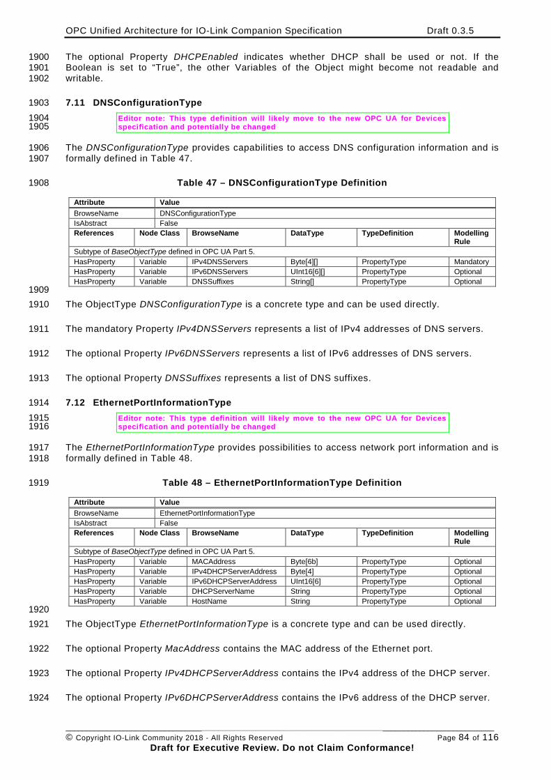
OPC Unified Architecture for IO-Link Companion Specification Draft 0.3.5
________________________________________________________________________________________________________ © Copyright IO-Link Community 2018 - All Rights Reserved Page 84 of 116
Draft for Executive Review. Do not Claim Conformance!
The optional Property DHCPEnabled indicates whether DHCP shall be used or not. If the 1900 Boolean is set to “True”, the other Variables of the Object might become not readable and 1901 writable. 1902
7.11 DNSConfigurationType 1903 Editor note: This type definition will likely move to the new OPC UA for Devices 1904 specification and potentially be changed 1905
The DNSConfigurationType provides capabilities to access DNS configuration information and is 1906 formally defined in Table 47. 1907
Table 47 – DNSConfigurationType Definition 1908
Attribute Value BrowseName DNSConfigurationType IsAbstract False References Node Class BrowseName DataType TypeDefinition Modelling
Rule Subtype of BaseObjectType defined in OPC UA Part 5. HasProperty Variable IPv4DNSServers Byte[4][] PropertyType Mandatory HasProperty Variable IPv6DNSServers UInt16[6][] PropertyType Optional HasProperty Variable DNSSuffixes String[] PropertyType Optional
1909 The ObjectType DNSConfigurationType is a concrete type and can be used directly. 1910
The mandatory Property IPv4DNSServers represents a list of IPv4 addresses of DNS servers. 1911
The optional Property IPv6DNSServers represents a list of IPv6 addresses of DNS servers. 1912
The optional Property DNSSuffixes represents a list of DNS suffixes. 1913
7.12 EthernetPortInformationType 1914 Editor note: This type definition will likely move to the new OPC UA for Devices 1915 specification and potentially be changed 1916
The EthernetPortInformationType provides possibilities to access network port information and is 1917 formally defined in Table 48. 1918
Table 48 – EthernetPortInformationType Definition 1919
Attribute Value BrowseName EthernetPortInformationType IsAbstract False References Node Class BrowseName DataType TypeDefinition Modelling
Rule Subtype of BaseObjectType defined in OPC UA Part 5. HasProperty Variable MACAddress Byte[6b] PropertyType Optional HasProperty Variable IPv4DHCPServerAddress Byte[4] PropertyType Optional HasProperty Variable IPv6DHCPServerAddress UInt16[6] PropertyType Optional HasProperty Variable DHCPServerName String PropertyType Optional HasProperty Variable HostName String PropertyType Optional
1920 The ObjectType EthernetPortInformationType is a concrete type and can be used directly. 1921
The optional Property MacAddress contains the MAC address of the Ethernet port. 1922
The optional Property IPv4DHCPServerAddress contains the IPv4 address of the DHCP server. 1923
The optional Property IPv6DHCPServerAddress contains the IPv6 address of the DHCP server. 1924
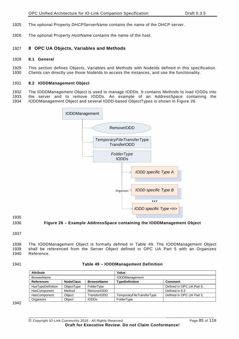
OPC Unified Architecture for IO-Link Companion Specification Draft 0.3.5
________________________________________________________________________________________________________ © Copyright IO-Link Community 2018 - All Rights Reserved Page 85 of 116
Draft for Executive Review. Do not Claim Conformance!
The optional Property DHCPServerName contains the name of the DHCP server. 1925
The optional Property HostName contains the name of the host. 1926
8 OPC UA Objects, Variables and Methods 1927
8.1 General 1928
This section defines Objects, Variables and Methods with NodeIds defined in this specification. 1929 Clients can directly use those NodeIds to access the instances, and use the functionality. 1930
8.2 IODDManagement Object 1931
The IODDManagement Object is used to manage IODDs. It contains Methods to load IODDs into 1932 the server and to remove IODDs. An example of an AddressSpace containing the 1933 IODDManagement Object and several IODD-based ObjectTypes is shown in Figure 26. 1934
IODDManagement
RemoveIODD
TemporaryFileTransferTypeTransferIODD
FolderTypeIODDs
IODD specific Type A
IODD specific Type B
IODD specific Type <n>
...Organizes
1935 Figure 26 – Example AddressSpace containing the IODDManagement Object 1936
1937
The IODDManagement Object is formally defined in Table 49. The IODDManagement Object 1938 shall be referenced from the Server Object defined in OPC UA Part 5 with an Organizes 1939 Reference. 1940
Table 49 – IODDManagement Definition 1941
Attribute Value BrowseName IODDManagement References NodeClass BrowseName TypeDefinition Comment HasTypeDefinition ObjectType FolderType Defined in OPC UA Part 5. HasComponent Method RemoveIODD Defined in 8.3 HasComponent Object TransferIODD TemporaryFileTransferType Defined in OPC UA Part 5. Organizes Object IODDs FolderType
1942
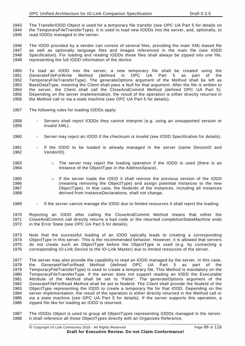
OPC Unified Architecture for IO-Link Companion Specification Draft 0.3.5
________________________________________________________________________________________________________ © Copyright IO-Link Community 2018 - All Rights Reserved Page 86 of 116
Draft for Executive Review. Do not Claim Conformance!
The TransferIODD Object is used for a temporary file transfer (see OPC UA Part 5 for details on 1943 the TemporaryFileTransferType). It is used to load new IODDs into the server, and, optionally, to 1944 read IODDs managed in the server. 1945
The IODD provided by a vendor can consist of several files, providing the main XML-based file 1946 as well as optionally language files and images referenced in the main file (see IODD 1947 Specification). For loading and reading IODDs those files shall always be zipped into one file, 1948 representing the full IODD information of the device. 1949
To load an IODD into the server, a new temporary file shall be created using the 1950 GenerateFileForWrite Method (defined in OPC UA Part 5 as part of the 1951 TemporaryFileTransferType). The generateOptions argument of the Method shall be left as 1952 BaseDataType, meaning the Client shall pass a Null for that argument. After the file is written to 1953 the server, the Client shall call the CloseAndCommit Method (defined OPC UA Part 5). 1954 Depending on the server implementation, the result of the operation is either directly returned in 1955 the Method call or via a state machine (see OPC UA Part 5 for details). 1956
The following rules for loading IODDs apply: 1957
- Servers shall reject IODDs they cannot interpret (e.g. using an unsupported version or 1958 invalid XML). 1959
- Server may reject an IODD if the checksum is invalid (see IODD Specification for details). 1960
- If the IODD to be loaded is already managed in the server (same DeviceID and 1961 VendorID). 1962
o The server may reject the loading operation if the IODD is used (there is an 1963 Instance of the ObjectType in the AddressSpace). 1964
o If the server loads the IODD it shall remove the previous version of the IODD 1965 (meaning removing the ObjectType) and assign potential Instances to the new 1966 ObjectType). In that case, the NodeIds of the Instances, including all Instances 1967 derived from InstanceDeclarations, shall not change. 1968
- If the server cannot manage the IODD due to limited resources it shall reject the loading. 1969
Rejecting an IODD after calling the CloseAndCommit Method means that either the 1970 CloseAndCommit call directly returns a bad code or the returned completionStateMachine ends 1971 in the Error State (see OPC UA Part 5 for details). 1972
Note that the successful loading of an IODD typically leads to creating a corresponding 1973 ObjectType in this server. This is the recommended behavior. However, it is allowed that servers 1974 do not create such an ObjectType before the ObjectType is used (e.g. by connecting a 1975 corresponding IO-Link Device to the IO-Link Master) due to limited resources of the server. 1976
The server may also provide the capability to read an IODD managed by the server. In this case, 1977 the GenerateFileForRead Method (defined OPC UA Part 5 as part of the 1978 TemporaryFileTransferType) is used to create a temporary file. This Method is mandatory on the 1979 TemporaryFileTransferType. If the server does not support reading an IODD the Executable 1980 Attribute of the Method shall be set to “False”. The generateOptions argument of the 1981 GenerateFileForRead Method shall be set to NodeId. The Client shall provide the NodeId of the 1982 ObjectType representing the IODD to create a temporary file for that IODD. Depending on the 1983 server implementation, the result of the operation is either directly returned in the Method call or 1984 via a state machine (see OPC UA Part 5 for details). If the server supports this operation, a 1985 zipped file like for loading an IODD is returned. 1986
The IODDs Object is used to group all ObjectTypes representing IODDs managed in the server. 1987 It shall reference all those ObjectTypes directly with an Organizes Reference. 1988
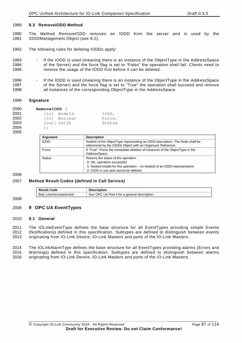
OPC Unified Architecture for IO-Link Companion Specification Draft 0.3.5
________________________________________________________________________________________________________ © Copyright IO-Link Community 2018 - All Rights Reserved Page 87 of 116
Draft for Executive Review. Do not Claim Conformance!
8.3 RemoveIODD Method 1989
The Method RemoveIODD removes an IODD from the server and is used by the 1990 IODDManagement Object (see 8.2). 1991
The following rules for deleting IODDs apply: 1992
- If the IODD is used (meaning there is an instance of the ObjectType in the AddressSpace 1993 of the Server) and the force flag is set to “False” the operation shall fail. Clients need to 1994 remove the usage of the IODD first before it can be deleted. 1995
- If the IODD is used (meaning there is an instance of the ObjectType in the AddressSpace 1996 of the Server) and the force flag is set to "True" the operation shall succeed and remove 1997 all instances of the corresponding ObjectType in the AddressSpace. 1998
Signature 1999
RemoveIODD ( 2000 [in] NodeId IODD, 2001 [in] Boolean Force, 2002 [out] Int32 Status 2003 ); 2004 2005
Argument Description IODD NodeId of the ObjectType representing an IODD description. The Node shall be
referenced by the IODDs Object with an Organizes Reference. Force If "True": Force the immediate deletion of instances of the ObjectType in the
AddressSpace. Status Returns the status of the operation.
0: OK, operation successful -1: NodeId invalid for this operation – no NodeId of an IODD representation -2: IODD in use and cannot be deleted
2006 Method Result Codes (defined in Call Service) 2007
Result Code Description Bad_UserAccessDenied See OPC UA Part 4 for a general description.
2008
9 OPC UA EventTypes 2009
9.1 General 2010
The IOLinkEventType defines the base structure for all EventTypes providing simple Events 2011 (Notifications) defined in this specification. Subtypes are defined to distinguish between events 2012 originating from IO-Link Device, IO-Link Masters and ports of the IO-Link Masters. 2013
The IOLinkAlarmType defines the base structure for all EventTypes providing alarms (Errors and 2014 Warnings) defined in this specification. Subtypes are defined to distinguish between alarms 2015 originating from IO-Link Device, IO-Link Masters and ports of the IO-Link Masters. 2016
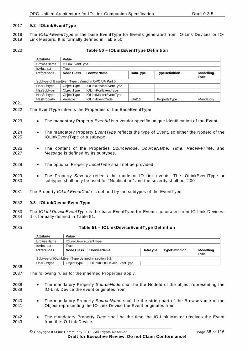
OPC Unified Architecture for IO-Link Companion Specification Draft 0.3.5
________________________________________________________________________________________________________ © Copyright IO-Link Community 2018 - All Rights Reserved Page 88 of 116
Draft for Executive Review. Do not Claim Conformance!
9.2 IOLinkEventType 2017
The IOLinkEventType is the base EventType for Events generated from IO-Link Devices or IO-2018 Link Masters. It is formally defined in Table 50. 2019
Table 50 – IOLinkEventType Definition 2020
Attribute Value BrowseName IOLinkEventType IsAbstract True References Node Class BrowseName DataType TypeDefinition Modelling
Rule Subtype of BaseEventType defined in OPC UA Part 5. HasSubtype ObjectType IOLinkDeviceEventType HasSubtype ObjectType IOLinkPortEventType HasSubtype ObjectType IOLinkMasterEventType HasProperty Variable IOLinkEventCode UInt16 PropertyType Mandatory
2021 The EventType inherits the Properties of the BaseEventType. 2022
• The mandatory Property EventId is a vendor-specific unique identification of the Event. 2023
• The mandatory Property EventType reflects the type of Event, so either the NodeId of the 2024 IOLinkEventType or a subtype. 2025
• The content of the Properties SourceNode, SourceName, Time, ReceiveTime, and 2026 Message is defined by its subtypes. 2027
• The optional Property LocalTime shall not be provided. 2028
• The Property Severity reflects the mode of IO-Link events. The IOLinkEventType or 2029 subtypes shall only be used for “Notification” and the severity shall be “200”. 2030
The Property IOLinkEventCode is defined by the subtypes of the EventType. 2031
9.3 IOLinkDeviceEventType 2032
The IOLinkDeviceEventType is the base EventType for Events generated from IO-Link Devices. 2033 It is formally defined in Table 51. 2034
Table 51 – IOLinkDeviceEventType Definition 2035
Attribute Value BrowseName IOLinkDeviceEventType IsAbstract True References Node Class BrowseName DataType TypeDefinition Modelling
Rule Subtype of IOLinkEventType defined in section 9.2. HasSubtype ObjectType IOLinkIODDDeviceEventType
2036 The following rules for the inherited Properties apply. 2037
• The mandatory Property SourceNode shall be the NodeId of the object representing the 2038 IO-Link Device the event originates from. 2039
• The mandatory Property SourceName shall be the string part of the BrowseName of the 2040 Object representing the IO-Link Device the Event originates from. 2041
• The mandatory Property Time shall be the time the IO-Link Master receives the Event 2042 from the IO-Link Device. 2043
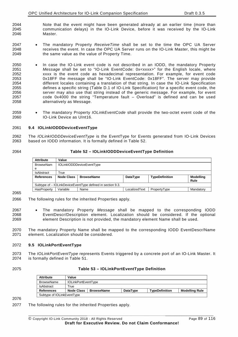
OPC Unified Architecture for IO-Link Companion Specification Draft 0.3.5
________________________________________________________________________________________________________ © Copyright IO-Link Community 2018 - All Rights Reserved Page 89 of 116
Draft for Executive Review. Do not Claim Conformance!
Note that the event might have been generated already at an earlier time (more than 2044 communication delays) in the IO-Link Device, before it was received by the IO-Link 2045 Master. 2046
• The mandatory Property ReceiveTime shall be set to the time the OPC UA Server 2047 receives the event. In case the OPC UA Server runs on the IO-Link Master, this might be 2048 the same value as the value of Property Time. 2049
• In case the IO-Link event code is not described in an IODD, the mandatory Property 2050 Message shall be set to “IO-Link EventCode: 0x<xxxx>” for the English locale, where 2051 xxxx is the event code as hexadecimal representation. For example, for event code 2052 0x18FF the message shall be “IO-Link EventCode: 0x18FF”. The server may provide 2053 different locales containing a translation of that string. In case the IO-Link Specification 2054 defines a specific string (Table D.1 of IO-Link Specification) for a specific event code, the 2055 server may also use that string instead of the generic message. For example, for event 2056 code 0x4000 the string “Temperature fault – Overload” is defined and can be used 2057 alternatively as Message. 2058
• The mandatory Property IOLinkEventCode shall provide the two-octet event code of the 2059 IO-Link Device as UInt16. 2060
9.4 IOLinkIODDDeviceEventType 2061
The IOLinkIODDDeviceEventType is the EventType for Events generated from IO-Link Devices 2062 based on IODD information. It is formally defined in Table 52. 2063
Table 52 – IOLinkIODDDeviceEventType Definition 2064
Attribute Value BrowseName
IOLinkIODDDeviceEventType
IsAbstract True References Node Class BrowseName DataType TypeDefinition Modelling
Rule Subtype of – IOLinkDeviceEventType defined in section 9.3. HasProperty Variable Name LocalizedText PropertyType Mandatory
2065 The following rules for the inherited Properties apply. 2066
• The mandatory Property Message shall be mapped to the corresponding IODD 2067 EventDescr/Description element. Localization should be considered. If the optional 2068 element Description is not provided, the mandatory element Name shall be used. 2069
The mandatory Property Name shall be mapped to the corresponding IODD EventDescr/Name 2070 element. Localization should be considered. 2071
9.5 IOLinkPortEventType 2072
The IOLinkPortEventType represents Events triggered by a concrete port of an IO-Link Master. It 2073 is formally defined in Table 51. 2074
Table 53 – IOLinkPortEventType Definition 2075
Attribute Value BrowseName IOLinkPortEventType IsAbstract True References Node Class BrowseName DataType TypeDefinition Modelling Rule Subtype of IOLinkEventType
2076 The following rules for the inherited Properties apply. 2077
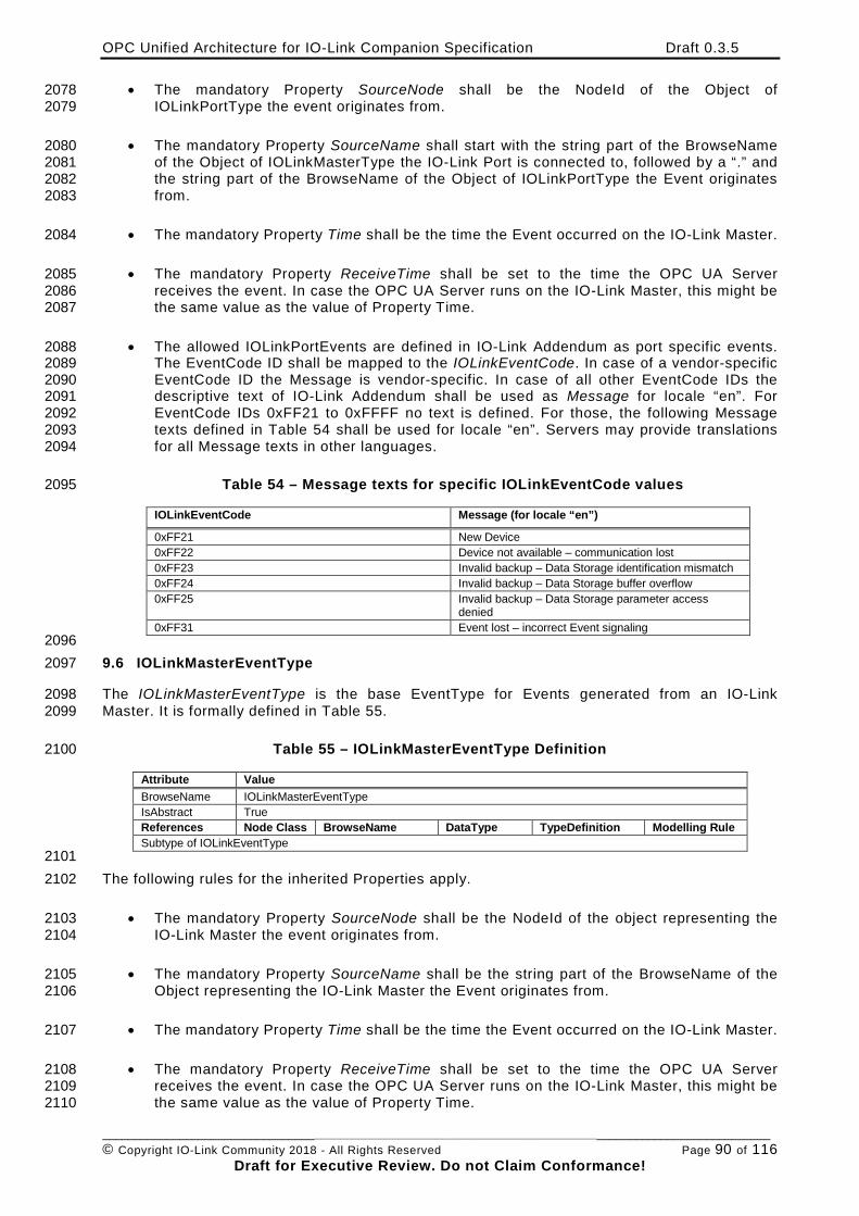
OPC Unified Architecture for IO-Link Companion Specification Draft 0.3.5
________________________________________________________________________________________________________ © Copyright IO-Link Community 2018 - All Rights Reserved Page 90 of 116
Draft for Executive Review. Do not Claim Conformance!
• The mandatory Property SourceNode shall be the NodeId of the Object of 2078 IOLinkPortType the event originates from. 2079
• The mandatory Property SourceName shall start with the string part of the BrowseName 2080 of the Object of IOLinkMasterType the IO-Link Port is connected to, followed by a “.” and 2081 the string part of the BrowseName of the Object of IOLinkPortType the Event originates 2082 from. 2083
• The mandatory Property Time shall be the time the Event occurred on the IO-Link Master. 2084
• The mandatory Property ReceiveTime shall be set to the time the OPC UA Server 2085 receives the event. In case the OPC UA Server runs on the IO-Link Master, this might be 2086 the same value as the value of Property Time. 2087
• The allowed IOLinkPortEvents are defined in IO-Link Addendum as port specific events. 2088 The EventCode ID shall be mapped to the IOLinkEventCode. In case of a vendor-specific 2089 EventCode ID the Message is vendor-specific. In case of all other EventCode IDs the 2090 descriptive text of IO-Link Addendum shall be used as Message for locale “en”. For 2091 EventCode IDs 0xFF21 to 0xFFFF no text is defined. For those, the following Message 2092 texts defined in Table 54 shall be used for locale “en”. Servers may provide translations 2093 for all Message texts in other languages. 2094
Table 54 – Message texts for specific IOLinkEventCode values 2095
IOLinkEventCode Message (for locale “en”)
0xFF21 New Device 0xFF22 Device not available – communication lost 0xFF23 Invalid backup – Data Storage identification mismatch 0xFF24 Invalid backup – Data Storage buffer overflow 0xFF25 Invalid backup – Data Storage parameter access
denied 0xFF31 Event lost – incorrect Event signaling
2096 9.6 IOLinkMasterEventType 2097
The IOLinkMasterEventType is the base EventType for Events generated from an IO-Link 2098 Master. It is formally defined in Table 55. 2099
Table 55 – IOLinkMasterEventType Definition 2100
Attribute Value BrowseName IOLinkMasterEventType IsAbstract True References Node Class BrowseName DataType TypeDefinition Modelling Rule Subtype of IOLinkEventType
2101 The following rules for the inherited Properties apply. 2102
• The mandatory Property SourceNode shall be the NodeId of the object representing the 2103 IO-Link Master the event originates from. 2104
• The mandatory Property SourceName shall be the string part of the BrowseName of the 2105 Object representing the IO-Link Master the Event originates from. 2106
• The mandatory Property Time shall be the time the Event occurred on the IO-Link Master. 2107
• The mandatory Property ReceiveTime shall be set to the time the OPC UA Server 2108 receives the event. In case the OPC UA Server runs on the IO-Link Master, this might be 2109 the same value as the value of Property Time. 2110
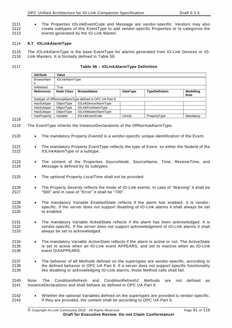
OPC Unified Architecture for IO-Link Companion Specification Draft 0.3.5
________________________________________________________________________________________________________ © Copyright IO-Link Community 2018 - All Rights Reserved Page 91 of 116
Draft for Executive Review. Do not Claim Conformance!
• The Properties IOLinkEventCode and Message are vendor-specific. Vendors may also 2111 create subtypes of this EventType to add vendor-specific Properties or to categorize the 2112 events generated by the IO-Link Master. 2113
9.7 IOLinkAlarmType 2114
The IOLinkAlarmType is the base EventType for alarms generated from IO-Link Devices or IO-2115 Link Masters. It is formally defined in Table 56. 2116
Table 56 – IOLinkAlarmType Definition 2117
Attribute Value BrowseName
IOLinkAlarmType
IsAbstract True References Node Class BrowseName DataType TypeDefinition Modelling
Rule Subtype of OffNormalAlarmType defined in OPC UA Part 9. HasSubtype ObjectType IOLinkDeviceAlarmType HasSubtype ObjectType IOLinkPortAlarmType HasSubtype ObjectType IOLinkMasterAlarmType HasProperty Variable IOLinkEventCode UInt16 PropertyType Mandatory
2118 The EventType inherits the InstanceDeclarations of the OffNormalAlarmType. 2119
• The mandatory Property EventId is a vendor-specific unique identification of the Event. 2120
• The mandatory Property EventType reflects the type of Event, so either the NodeId of the 2121 IOLinkAlarmType or a subtype. 2122
• The content of the Properties SourceNode, SourceName, Time, ReceiveTime, and 2123 Message is defined by its subtypes. 2124
• The optional Property LocalTime shall not be provided. 2125
• The Property Severity reflects the mode of IO-Link events. In case of “Warning” it shall be 2126 “500” and in case of “Error” it shall be “700”. 2127
• The mandatory Variable EnabledState reflects if the alarm has enabled. It is vendor-2128 specific. If the server does not support disabling of IO-Link alarms it shall always be set 2129 to enabled. 2130
• The mandatory Variable AckedState reflects if the alarm has been acknowledged. It is 2131 vendor-specific. If the server does not support acknowledgment of IO-Link alarms it shall 2132 always be set to acknowledged. 2133
• The mandatory Variable ActiveState reflects if the alarm is active or not. The ActiveState 2134 is set to active when an IO-Link event APPEARS, and set to inactive when an IO-Link 2135 event DISAPPEARS. 2136
• The behavior of all Methods defined on the supertypes are vendor-specific, according to 2137 the defined behavior in OPC UA Part 9. If a server does not support specific functionality 2138 like disabling or acknowledging IO-Link alarms, those Method calls shall fail. 2139
Note: The ConditionRefresh and ConditionRefresh2 Methods are not defined as 2140 InstanceDeclarations and shall behave as defined in OPC UA Part 9. 2141
• Whether the optional Variables defined on the supertypes are provided is vendor-specific. 2142 If they are provided, the content shall be according to OPC UA Part 9. 2143
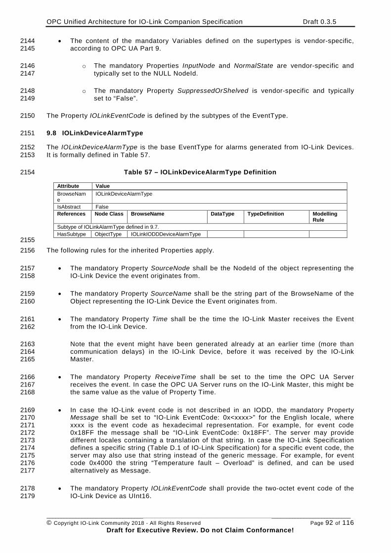
OPC Unified Architecture for IO-Link Companion Specification Draft 0.3.5
________________________________________________________________________________________________________ © Copyright IO-Link Community 2018 - All Rights Reserved Page 92 of 116
Draft for Executive Review. Do not Claim Conformance!
• The content of the mandatory Variables defined on the supertypes is vendor-specific, 2144 according to OPC UA Part 9. 2145
o The mandatory Properties InputNode and NormalState are vendor-specific and 2146 typically set to the NULL NodeId. 2147
o The mandatory Property SuppressedOrShelved is vendor-specific and typically 2148 set to “False”. 2149
The Property IOLinkEventCode is defined by the subtypes of the EventType. 2150
9.8 IOLinkDeviceAlarmType 2151
The IOLinkDeviceAlarmType is the base EventType for alarms generated from IO-Link Devices. 2152 It is formally defined in Table 57. 2153
Table 57 – IOLinkDeviceAlarmType Definition 2154
Attribute Value BrowseName
IOLinkDeviceAlarmType
IsAbstract False References Node Class BrowseName DataType TypeDefinition Modelling
Rule Subtype of IOLinkAlarmType defined in 9.7. HasSubtype ObjectType IOLinkIODDDeviceAlarmType
2155 The following rules for the inherited Properties apply. 2156
• The mandatory Property SourceNode shall be the NodeId of the object representing the 2157 IO-Link Device the event originates from. 2158
• The mandatory Property SourceName shall be the string part of the BrowseName of the 2159 Object representing the IO-Link Device the Event originates from. 2160
• The mandatory Property Time shall be the time the IO-Link Master receives the Event 2161 from the IO-Link Device. 2162
Note that the event might have been generated already at an earlier time (more than 2163 communication delays) in the IO-Link Device, before it was received by the IO-Link 2164 Master. 2165
• The mandatory Property ReceiveTime shall be set to the time the OPC UA Server 2166 receives the event. In case the OPC UA Server runs on the IO-Link Master, this might be 2167 the same value as the value of Property Time. 2168
• In case the IO-Link event code is not described in an IODD, the mandatory Property 2169 Message shall be set to “IO-Link EventCode: 0x<xxxx>” for the English locale, where 2170 xxxx is the event code as hexadecimal representation. For example, for event code 2171 0x18FF the message shall be “IO-Link EventCode: 0x18FF”. The server may provide 2172 different locales containing a translation of that string. In case the IO-Link Specification 2173 defines a specific string (Table D.1 of IO-Link Specification) for a specific event code, the 2174 server may also use that string instead of the generic message. For example, for event 2175 code 0x4000 the string “Temperature fault – Overload” is defined, and can be used 2176 alternatively as Message. 2177
• The mandatory Property IOLinkEventCode shall provide the two-octet event code of the 2178 IO-Link Device as UInt16. 2179
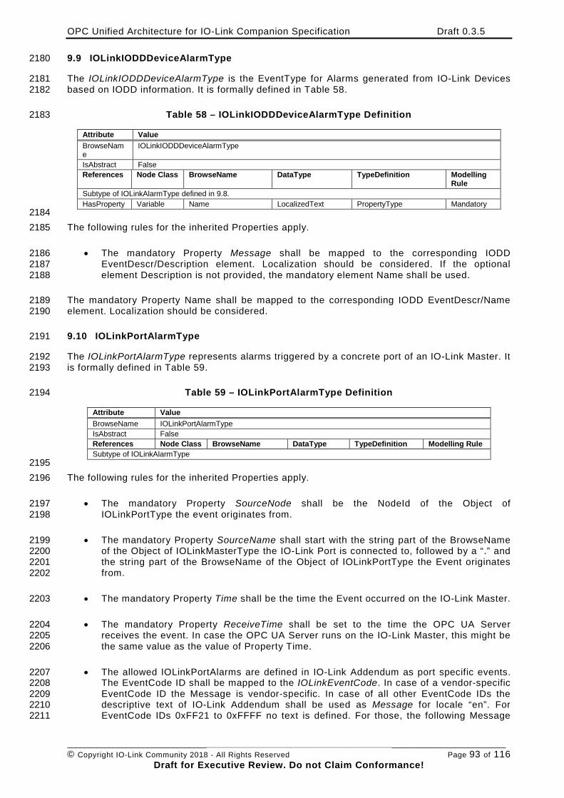
OPC Unified Architecture for IO-Link Companion Specification Draft 0.3.5
________________________________________________________________________________________________________ © Copyright IO-Link Community 2018 - All Rights Reserved Page 93 of 116
Draft for Executive Review. Do not Claim Conformance!
9.9 IOLinkIODDDeviceAlarmType 2180
The IOLinkIODDDeviceAlarmType is the EventType for Alarms generated from IO-Link Devices 2181 based on IODD information. It is formally defined in Table 58. 2182
Table 58 – IOLinkIODDDeviceAlarmType Definition 2183
Attribute Value BrowseName
IOLinkIODDDeviceAlarmType
IsAbstract False References Node Class BrowseName DataType TypeDefinition Modelling
Rule Subtype of IOLinkAlarmType defined in 9.8. HasProperty Variable Name LocalizedText PropertyType Mandatory
2184 The following rules for the inherited Properties apply. 2185
• The mandatory Property Message shall be mapped to the corresponding IODD 2186 EventDescr/Description element. Localization should be considered. If the optional 2187 element Description is not provided, the mandatory element Name shall be used. 2188
The mandatory Property Name shall be mapped to the corresponding IODD EventDescr/Name 2189 element. Localization should be considered. 2190
9.10 IOLinkPortAlarmType 2191
The IOLinkPortAlarmType represents alarms triggered by a concrete port of an IO-Link Master. It 2192 is formally defined in Table 59. 2193
Table 59 – IOLinkPortAlarmType Definition 2194
Attribute Value BrowseName IOLinkPortAlarmType IsAbstract False References Node Class BrowseName DataType TypeDefinition Modelling Rule Subtype of IOLinkAlarmType
2195 The following rules for the inherited Properties apply. 2196
• The mandatory Property SourceNode shall be the NodeId of the Object of 2197 IOLinkPortType the event originates from. 2198
• The mandatory Property SourceName shall start with the string part of the BrowseName 2199 of the Object of IOLinkMasterType the IO-Link Port is connected to, followed by a “.” and 2200 the string part of the BrowseName of the Object of IOLinkPortType the Event originates 2201 from. 2202
• The mandatory Property Time shall be the time the Event occurred on the IO-Link Master. 2203
• The mandatory Property ReceiveTime shall be set to the time the OPC UA Server 2204 receives the event. In case the OPC UA Server runs on the IO-Link Master, this might be 2205 the same value as the value of Property Time. 2206
• The allowed IOLinkPortAlarms are defined in IO-Link Addendum as port specific events. 2207 The EventCode ID shall be mapped to the IOLinkEventCode. In case of a vendor-specific 2208 EventCode ID the Message is vendor-specific. In case of all other EventCode IDs the 2209 descriptive text of IO-Link Addendum shall be used as Message for locale “en”. For 2210 EventCode IDs 0xFF21 to 0xFFFF no text is defined. For those, the following Message 2211
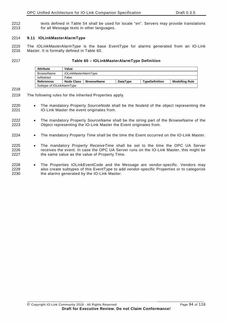
OPC Unified Architecture for IO-Link Companion Specification Draft 0.3.5
________________________________________________________________________________________________________ © Copyright IO-Link Community 2018 - All Rights Reserved Page 94 of 116
Draft for Executive Review. Do not Claim Conformance!
texts defined in Table 54 shall be used for locale “en”. Servers may provide translations 2212 for all Message texts in other languages. 2213
9.11 IOLinkMasterAlarmType 2214
The IOLinkMasterAlarmType is the base EventType for alarms generated from an IO-Link 2215 Master. It is formally defined in Table 60. 2216
Table 60 – IOLinkMasterAlarmType Definition 2217
Attribute Value BrowseName IOLinkMasterAlarmType IsAbstract False References Node Class BrowseName DataType TypeDefinition Modelling Rule Subtype of IOLinkAlarmType
2218 The following rules for the inherited Properties apply. 2219
• The mandatory Property SourceNode shall be the NodeId of the object representing the 2220 IO-Link Master the event originates from. 2221
• The mandatory Property SourceName shall be the string part of the BrowseName of the 2222 Object representing the IO-Link Master the Event originates from. 2223
• The mandatory Property Time shall be the time the Event occurred on the IO-Link Master. 2224
• The mandatory Property ReceiveTime shall be set to the time the OPC UA Server 2225 receives the event. In case the OPC UA Server runs on the IO-Link Master, this might be 2226 the same value as the value of Property Time. 2227
• The Properties IOLinkEventCode and the Message are vendor-specific. Vendors may 2228 also create subtypes of this EventType to add vendor-specific Properties or to categorize 2229 the alarms generated by the IO-Link Master. 2230
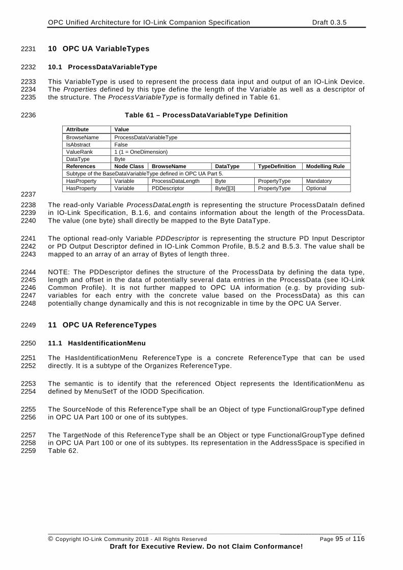
OPC Unified Architecture for IO-Link Companion Specification Draft 0.3.5
________________________________________________________________________________________________________ © Copyright IO-Link Community 2018 - All Rights Reserved Page 95 of 116
Draft for Executive Review. Do not Claim Conformance!
10 OPC UA VariableTypes 2231
10.1 ProcessDataVariableType 2232
This VariableType is used to represent the process data input and output of an IO-Link Device. 2233 The Properties defined by this type define the length of the Variable as well as a descriptor of 2234 the structure. The ProcessVariableType is formally defined in Table 61. 2235
Table 61 – ProcessDataVariableType Definition 2236
Attribute Value BrowseName ProcessDataVariableType IsAbstract False ValueRank 1 (1 = OneDimension) DataType Byte References Node Class BrowseName DataType TypeDefinition Modelling Rule Subtype of the BaseDataVariableType defined in OPC UA Part 5. HasProperty Variable ProcessDataLength Byte PropertyType Mandatory HasProperty Variable PDDescriptor Byte[][3] PropertyType Optional
2237 The read-only Variable ProcessDataLength is representing the structure ProcessDataIn defined 2238 in IO-Link Specification, B.1.6, and contains information about the length of the ProcessData. 2239 The value (one byte) shall directly be mapped to the Byte DataType. 2240
The optional read-only Variable PDDescriptor is representing the structure PD Input Descriptor 2241 or PD Output Descriptor defined in IO-Link Common Profile, B.5.2 and B.5.3. The value shall be 2242 mapped to an array of an array of Bytes of length three. 2243
NOTE: The PDDescriptor defines the structure of the ProcessData by defining the data type, 2244 length and offset in the data of potentially several data entries in the ProcessData (see IO-Link 2245 Common Profile). It is not further mapped to OPC UA information (e.g. by providing sub-2246 variables for each entry with the concrete value based on the ProcessData) as this can 2247 potentially change dynamically and this is not recognizable in time by the OPC UA Server. 2248
11 OPC UA ReferenceTypes 2249
11.1 HasIdentificationMenu 2250
The HasIdentificationMenu ReferenceType is a concrete ReferenceType that can be used 2251 directly. It is a subtype of the Organizes ReferenceType. 2252
The semantic is to identify that the referenced Object represents the IdentificationMenu as 2253 defined by MenuSetT of the IODD Specification. 2254
The SourceNode of this ReferenceType shall be an Object of type FunctionalGroupType defined 2255 in OPC UA Part 100 or one of its subtypes. 2256
The TargetNode of this ReferenceType shall be an Object or type FunctionalGroupType defined 2257 in OPC UA Part 100 or one of its subtypes. Its representation in the AddressSpace is specified in 2258 Table 62. 2259
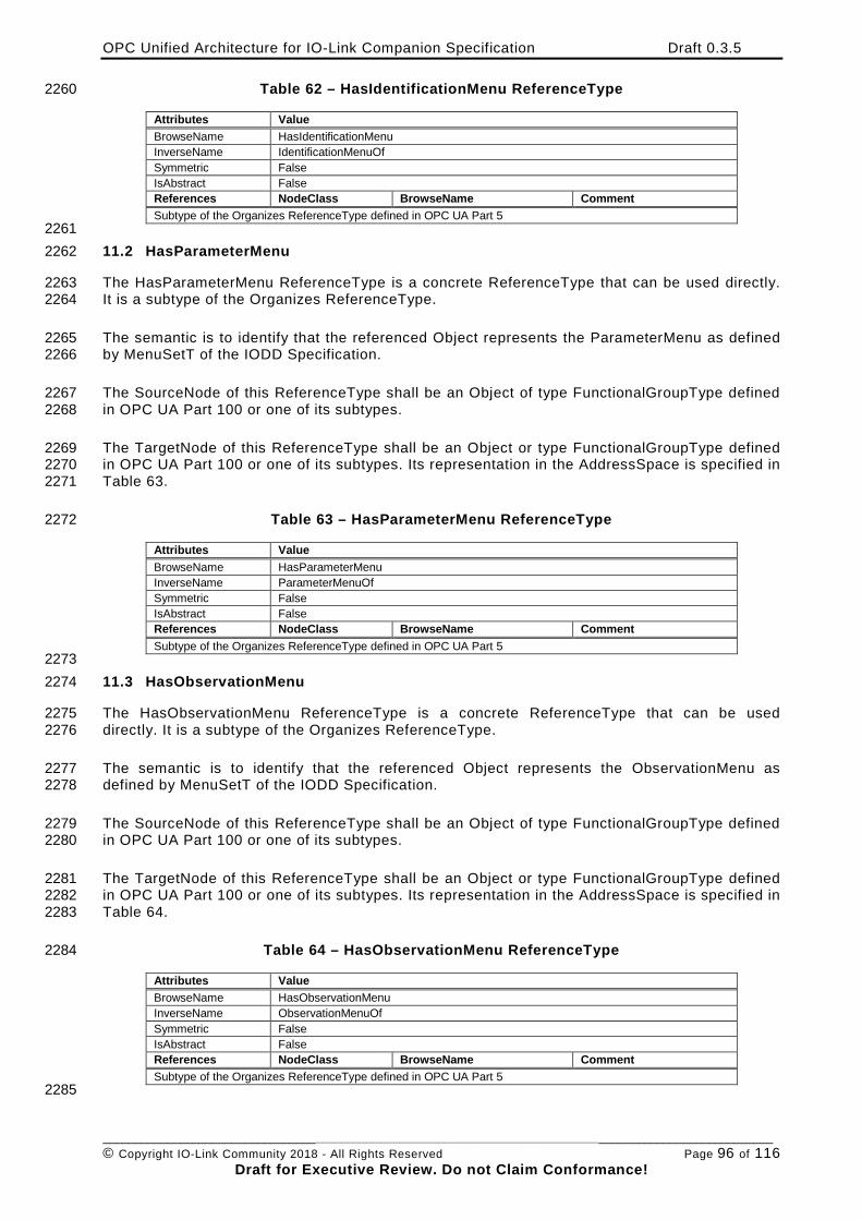
OPC Unified Architecture for IO-Link Companion Specification Draft 0.3.5
________________________________________________________________________________________________________ © Copyright IO-Link Community 2018 - All Rights Reserved Page 96 of 116
Draft for Executive Review. Do not Claim Conformance!
Table 62 – HasIdentificationMenu ReferenceType 2260
Attributes Value BrowseName HasIdentificationMenu InverseName IdentificationMenuOf Symmetric False IsAbstract False References NodeClass BrowseName Comment Subtype of the Organizes ReferenceType defined in OPC UA Part 5
2261 11.2 HasParameterMenu 2262
The HasParameterMenu ReferenceType is a concrete ReferenceType that can be used directly. 2263 It is a subtype of the Organizes ReferenceType. 2264
The semantic is to identify that the referenced Object represents the ParameterMenu as defined 2265 by MenuSetT of the IODD Specification. 2266
The SourceNode of this ReferenceType shall be an Object of type FunctionalGroupType defined 2267 in OPC UA Part 100 or one of its subtypes. 2268
The TargetNode of this ReferenceType shall be an Object or type FunctionalGroupType defined 2269 in OPC UA Part 100 or one of its subtypes. Its representation in the AddressSpace is specified in 2270 Table 63. 2271
Table 63 – HasParameterMenu ReferenceType 2272
Attributes Value BrowseName HasParameterMenu InverseName ParameterMenuOf Symmetric False IsAbstract False References NodeClass BrowseName Comment Subtype of the Organizes ReferenceType defined in OPC UA Part 5
2273 11.3 HasObservationMenu 2274
The HasObservationMenu ReferenceType is a concrete ReferenceType that can be used 2275 directly. It is a subtype of the Organizes ReferenceType. 2276
The semantic is to identify that the referenced Object represents the ObservationMenu as 2277 defined by MenuSetT of the IODD Specification. 2278
The SourceNode of this ReferenceType shall be an Object of type FunctionalGroupType defined 2279 in OPC UA Part 100 or one of its subtypes. 2280
The TargetNode of this ReferenceType shall be an Object or type FunctionalGroupType defined 2281 in OPC UA Part 100 or one of its subtypes. Its representation in the AddressSpace is specified in 2282 Table 64. 2283
Table 64 – HasObservationMenu ReferenceType 2284
Attributes Value BrowseName HasObservationMenu InverseName ObservationMenuOf Symmetric False IsAbstract False References NodeClass BrowseName Comment Subtype of the Organizes ReferenceType defined in OPC UA Part 5
2285
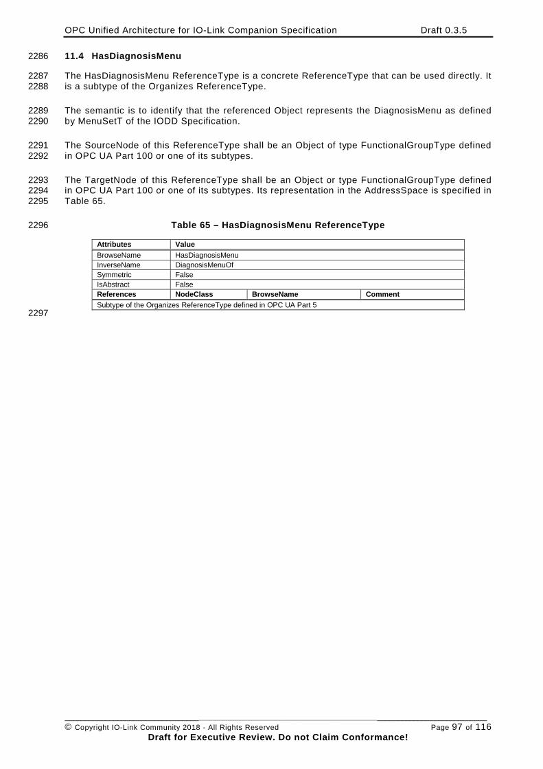
OPC Unified Architecture for IO-Link Companion Specification Draft 0.3.5
________________________________________________________________________________________________________ © Copyright IO-Link Community 2018 - All Rights Reserved Page 97 of 116
Draft for Executive Review. Do not Claim Conformance!
11.4 HasDiagnosisMenu 2286
The HasDiagnosisMenu ReferenceType is a concrete ReferenceType that can be used directly. It 2287 is a subtype of the Organizes ReferenceType. 2288
The semantic is to identify that the referenced Object represents the DiagnosisMenu as defined 2289 by MenuSetT of the IODD Specification. 2290
The SourceNode of this ReferenceType shall be an Object of type FunctionalGroupType defined 2291 in OPC UA Part 100 or one of its subtypes. 2292
The TargetNode of this ReferenceType shall be an Object or type FunctionalGroupType defined 2293 in OPC UA Part 100 or one of its subtypes. Its representation in the AddressSpace is specified in 2294 Table 65. 2295
Table 65 – HasDiagnosisMenu ReferenceType 2296
Attributes Value BrowseName HasDiagnosisMenu InverseName DiagnosisMenuOf Symmetric False IsAbstract False References NodeClass BrowseName Comment Subtype of the Organizes ReferenceType defined in OPC UA Part 5
2297
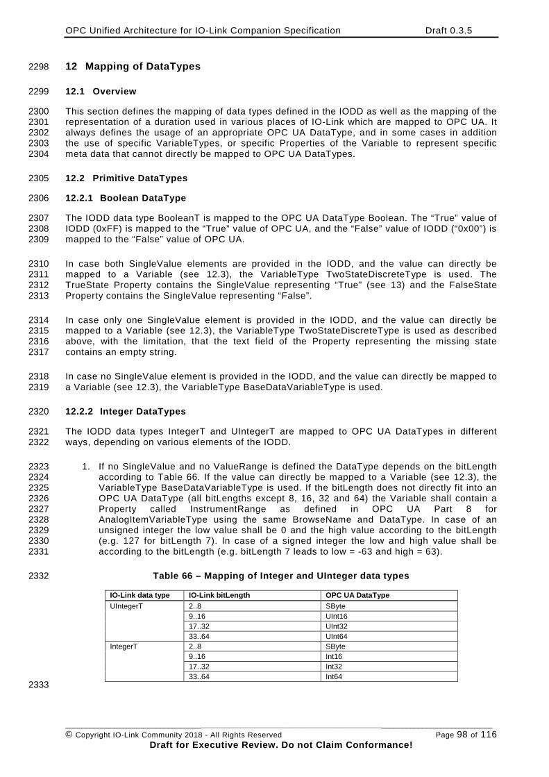
OPC Unified Architecture for IO-Link Companion Specification Draft 0.3.5
________________________________________________________________________________________________________ © Copyright IO-Link Community 2018 - All Rights Reserved Page 98 of 116
Draft for Executive Review. Do not Claim Conformance!
12 Mapping of DataTypes 2298
12.1 Overview 2299
This section defines the mapping of data types defined in the IODD as well as the mapping of the 2300 representation of a duration used in various places of IO-Link which are mapped to OPC UA. It 2301 always defines the usage of an appropriate OPC UA DataType, and in some cases in addition 2302 the use of specific VariableTypes, or specific Properties of the Variable to represent specific 2303 meta data that cannot directly be mapped to OPC UA DataTypes. 2304
12.2 Primitive DataTypes 2305
12.2.1 Boolean DataType 2306
The IODD data type BooleanT is mapped to the OPC UA DataType Boolean. The “True” value of 2307 IODD (0xFF) is mapped to the “True” value of OPC UA, and the “False” value of IODD (“0x00”) is 2308 mapped to the “False” value of OPC UA. 2309
In case both SingleValue elements are provided in the IODD, and the value can directly be 2310 mapped to a Variable (see 12.3), the VariableType TwoStateDiscreteType is used. The 2311 TrueState Property contains the SingleValue representing “True” (see 13) and the FalseState 2312 Property contains the SingleValue representing “False”. 2313
In case only one SingleValue element is provided in the IODD, and the value can directly be 2314 mapped to a Variable (see 12.3), the VariableType TwoStateDiscreteType is used as described 2315 above, with the limitation, that the text field of the Property representing the missing state 2316 contains an empty string. 2317
In case no SingleValue element is provided in the IODD, and the value can directly be mapped to 2318 a Variable (see 12.3), the VariableType BaseDataVariableType is used. 2319
12.2.2 Integer DataTypes 2320
The IODD data types IntegerT and UIntegerT are mapped to OPC UA DataTypes in different 2321 ways, depending on various elements of the IODD. 2322
1. If no SingleValue and no ValueRange is defined the DataType depends on the bitLength 2323 according to Table 66. If the value can directly be mapped to a Variable (see 12.3), the 2324 VariableType BaseDataVariableType is used. If the bitLength does not directly fit into an 2325 OPC UA DataType (all bitLengths except 8, 16, 32 and 64) the Variable shall contain a 2326 Property called InstrumentRange as defined in OPC UA Part 8 for 2327 AnalogItemVariableType using the same BrowseName and DataType. In case of an 2328 unsigned integer the low value shall be 0 and the high value according to the bitLength 2329 (e.g. 127 for bitLength 7). In case of a signed integer the low and high value shall be 2330 according to the bitLength (e.g. bitLength 7 leads to low = -63 and high = 63). 2331
Table 66 – Mapping of Integer and UInteger data types 2332
IO-Link data type IO-Link bitLength OPC UA DataType UIntegerT 2..8 SByte
9..16 UInt16 17..32 UInt32 33..64 UInt64
IntegerT 2..8 SByte 9..16 Int16 17..32 Int32 33..64 Int64
2333
OPC Unified Architecture for IO-Link Companion Specification Draft 0.3.5
________________________________________________________________________________________________________ © Copyright IO-Link Community 2018 - All Rights Reserved Page 99 of 116
Draft for Executive Review. Do not Claim Conformance!
2. If no SingleValue and exactly one ValueRange is defined, the same mapping as defined 2334 in (1) is used, except for the InstrumentRange Property. The InstrumentRange shall 2335 always be provided and be filled according to the ValueRange definition. 2336
3. If at least one SingleValue is defined and no ValueRange is defined: 2337 a. If all SingleValue values fit into the range of an Int32, an OPC UA Enumeration 2338
DataType is created, containing all SingleValue entries of the IODD definition in 2339 the EnumValues Property (see section 13). If the value can directly be mapped to 2340 a Variable (see section 12.3), the VariableType BaseDataVariableType shall be 2341 used 2342
b. If not all SingleValue values fit into the range of an Int32, the same mapping as 2343 defined in (1) is used with the following exceptions. If the value can directly be 2344 mapped to a Variable (see section 12.3), the VariableType 2345 MultiStateValueDiscreteType shall be used, and the EnumValues are filled 2346 according to the SingleValue entries (see section 13). The InstrumentRange 2347 Property is provided as according to (1). 2348
4. If no SingleValue and more than one ValueRange is defined the same mapping as 2349 defined in (1) is used with the following exceptions. If the value can directly be mapped to 2350 a Variable (see section 12.3), in addition to potentially providing the InstrumentRange 2351 Property (depending on the bitLength) another Property InstrumentRanges (see section 2352 13) is provided, containing an array of ranges, one entry for each ValueRange defined in 2353 the IODD. 2354
5. If at least one SingleValue and exactly one ValueRange is defined the same mapping as 2355 defined in (2) is used with the following exceptions. If the value can directly be mapped to 2356 a Variable (see section 12.3), an additional Property EnumValues (same as defined on 2357 MultiStateValueDiscreteType in OPC UA Part 8) is provided, with one entry for each 2358 SingleValue (see 13). 2359
6. If at least one SingleValue and more than one ValueRange is defined the same mapping 2360 as defined in (1) is used with the following exceptions. If the value can directly be 2361 mapped to a Variable (see section 12.3), an additional Property EnumValues (same as 2362 defined on MultiStateValueDiscreteType in OPC UA Part 8) is provided, with one entry for 2363 each SingleValue defined in the IODD, and in addition to potentially providing the 2364 InstrumentRange Property (depending on the bitLength) another Property 2365 InstrumentRanges (see section 13) is provided, containing an array of ranges, one entry 2366 for each ValueRange defined in the IODD. 2367
Note: Due to the meta data provided in the IODD an OPC UA Server can already identify that a write operation to a 2368 device will fail if the value is out of range. It is recommended that OPC UA Servers already check the value to avoid 2369 unnecessary communication to the IO-Link Device. 2370
12.2.3 Float DataType 2371
The IODD data type FloatT and the OPC UA DataType Float follow the same specification and 2372 can directly be mapped. 2373
In case the value can directly be mapped to a Variable (see section 12.3) the following rules 2374 apply: 2375
1. If no SingleValue and no ValueRange is defined, the VariableType 2376 BaseDataVariableType is used. 2377
2. If no SingleValue and exactly one ValueRange is defined, the VariableType 2378 BaseDataVariableType is used. The Variable shall have the additional Property 2379 InstrumentRange as defined in OPC UA Part 8 for AnalogItemVariableType using the 2380 same BrowseName and DataType. The InstrumentRange shall be filled according to the 2381 ValueRange definition. 2382
3. If at least one SingleValue is defined and no ValueRange is defined, the VariableType 2383 MultiStateValueDiscreteType shall be used, and the EnumValues filled according to the 2384 SingleValue entries (see section 13). 2385
4. If no SingleValue and more than one ValueRange is defined the VariableType 2386 BaseDataVariableType is used. The Variable shall have a Property InstrumentRanges 2387
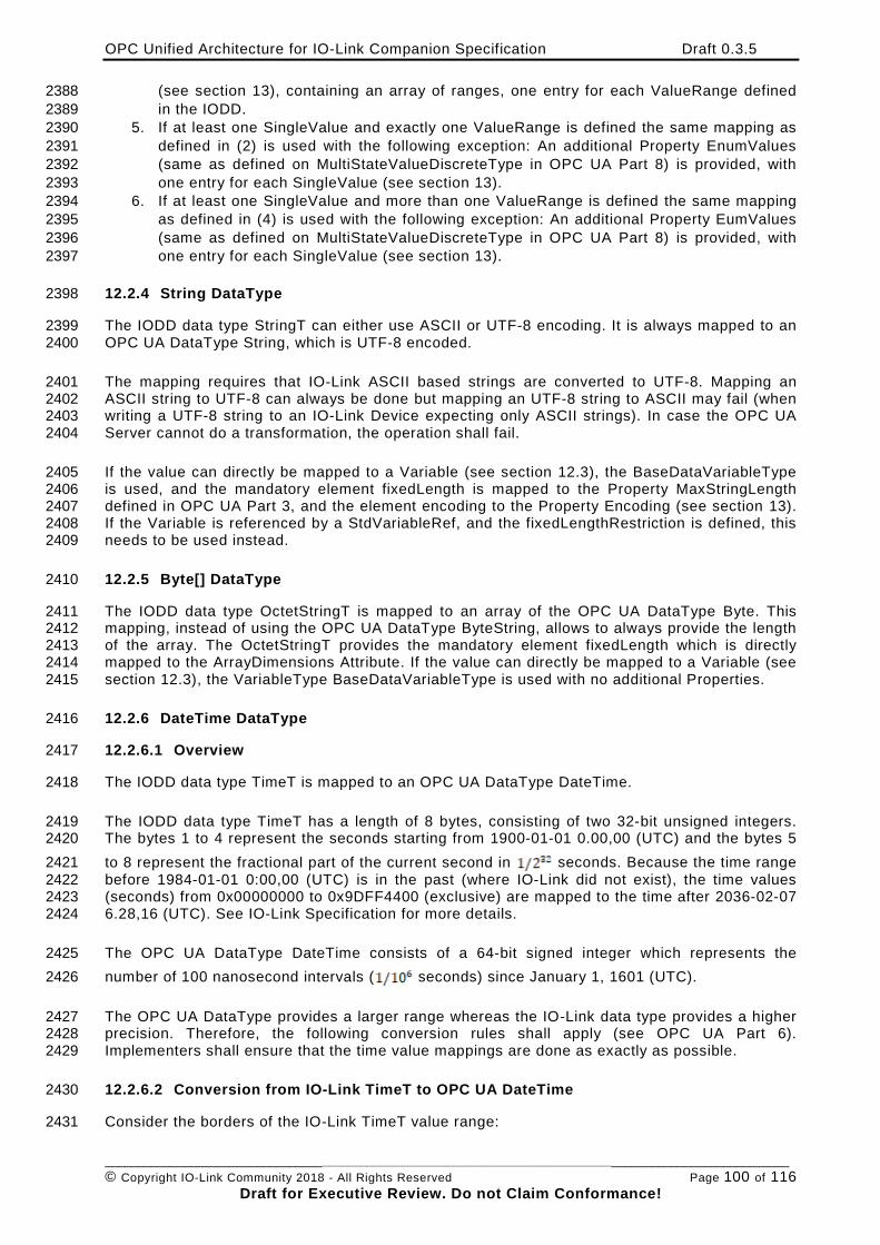
OPC Unified Architecture for IO-Link Companion Specification Draft 0.3.5
________________________________________________________________________________________________________ © Copyright IO-Link Community 2018 - All Rights Reserved Page 100 of 116
Draft for Executive Review. Do not Claim Conformance!
(see section 13), containing an array of ranges, one entry for each ValueRange defined 2388 in the IODD. 2389
5. If at least one SingleValue and exactly one ValueRange is defined the same mapping as 2390 defined in (2) is used with the following exception: An additional Property EnumValues 2391 (same as defined on MultiStateValueDiscreteType in OPC UA Part 8) is provided, with 2392 one entry for each SingleValue (see section 13). 2393
6. If at least one SingleValue and more than one ValueRange is defined the same mapping 2394 as defined in (4) is used with the following exception: An additional Property EumValues 2395 (same as defined on MultiStateValueDiscreteType in OPC UA Part 8) is provided, with 2396 one entry for each SingleValue (see section 13). 2397
12.2.4 String DataType 2398
The IODD data type StringT can either use ASCII or UTF-8 encoding. It is always mapped to an 2399 OPC UA DataType String, which is UTF-8 encoded. 2400
The mapping requires that IO-Link ASCII based strings are converted to UTF-8. Mapping an 2401 ASCII string to UTF-8 can always be done but mapping an UTF-8 string to ASCII may fail (when 2402 writing a UTF-8 string to an IO-Link Device expecting only ASCII strings). In case the OPC UA 2403 Server cannot do a transformation, the operation shall fail. 2404
If the value can directly be mapped to a Variable (see section 12.3), the BaseDataVariableType 2405 is used, and the mandatory element fixedLength is mapped to the Property MaxStringLength 2406 defined in OPC UA Part 3, and the element encoding to the Property Encoding (see section 13). 2407 If the Variable is referenced by a StdVariableRef, and the fixedLengthRestriction is defined, this 2408 needs to be used instead. 2409
12.2.5 Byte[] DataType 2410
The IODD data type OctetStringT is mapped to an array of the OPC UA DataType Byte. This 2411 mapping, instead of using the OPC UA DataType ByteString, allows to always provide the length 2412 of the array. The OctetStringT provides the mandatory element fixedLength which is directly 2413 mapped to the ArrayDimensions Attribute. If the value can directly be mapped to a Variable (see 2414 section 12.3), the VariableType BaseDataVariableType is used with no additional Properties. 2415
12.2.6 DateTime DataType 2416
12.2.6.1 Overview 2417
The IODD data type TimeT is mapped to an OPC UA DataType DateTime. 2418
The IODD data type TimeT has a length of 8 bytes, consisting of two 32-bit unsigned integers. 2419 The bytes 1 to 4 represent the seconds starting from 1900-01-01 0.00,00 (UTC) and the bytes 5 2420 to 8 represent the fractional part of the current second in seconds. Because the time range 2421 before 1984-01-01 0:00,00 (UTC) is in the past (where IO-Link did not exist), the time values 2422 (seconds) from 0x00000000 to 0x9DFF4400 (exclusive) are mapped to the time after 2036-02-07 2423 6.28,16 (UTC). See IO-Link Specification for more details. 2424
The OPC UA DataType DateTime consists of a 64-bit signed integer which represents the 2425 number of 100 nanosecond intervals ( seconds) since January 1, 1601 (UTC). 2426
The OPC UA DataType provides a larger range whereas the IO-Link data type provides a higher 2427 precision. Therefore, the following conversion rules shall apply (see OPC UA Part 6). 2428 Implementers shall ensure that the time value mappings are done as exactly as possible. 2429
12.2.6.2 Conversion from IO-Link TimeT to OPC UA DateTime 2430
Consider the borders of the IO-Link TimeT value range: 2431
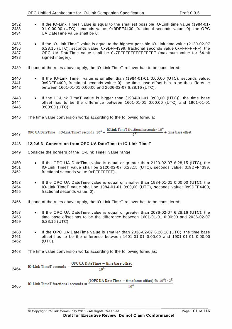
OPC Unified Architecture for IO-Link Companion Specification Draft 0.3.5
________________________________________________________________________________________________________ © Copyright IO-Link Community 2018 - All Rights Reserved Page 101 of 116
Draft for Executive Review. Do not Claim Conformance!
• If the IO-Link TimeT value is equal to the smallest possible IO-Link time value (1984-01-2432 01 0:00,00 (UTC), seconds value: 0x9DFF4400, fractional seconds value: 0), the OPC 2433 UA DateTime value shall be 0. 2434
• If the IO-Link TimeT value is equal to the highest possible IO-Link time value (2120-02-07 2435 6:28,15 (UTC), seconds value: 0x9DFF4399, fractional seconds value 0xFFFFFFFF), the 2436 OPC UA DateTime value shall be 0x7FFFFFFFFFFFFFFF (maximum value for 64-bit 2437 signed integer). 2438
If none of the rules above apply, the IO-Link TimeT rollover has to be considered: 2439
• If the IO-Link TimeT value is smaller than (1984-01-01 0:00,00 (UTC), seconds value: 2440 0x9DFF4400, fractional seconds value: 0), the time base offset has to be the difference 2441 between 1601-01-01 0:00:00 and 2036-02-07 6.28,16 (UTC). 2442
• If the IO-Link TimeT value is bigger than (1984-01-01 0:00,00 (UTC)), the time base 2443 offset has to be the difference between 1601-01-01 0:00:00 (UTC) and 1901-01-01 2444 0:00:00 (UTC). 2445
The time value conversion works according to the following formula: 2446
2447
12.2.6.3 Conversion from OPC UA DateTime to IO-Link TimeT 2448
Consider the borders of the IO-Link TimeT value range: 2449
• If the OPC UA DateTime value is equal or greater than 2120-02-07 6:28,15 (UTC), the 2450 IO-Link TimeT value shall be 2120-02-07 6:28,15 (UTC), seconds value: 0x9DFF4399, 2451 fractional seconds value 0xFFFFFFFF). 2452
• If the OPC UA DateTime value is equal or smaller than 1984-01-01 0:00,00 (UTC), the 2453 IO-Link TimeT value shall be 1984-01-01 0:00,00 (UTC), seconds value: 0x9DFF4400, 2454 fractional seconds value: 0). 2455
If none of the rules above apply, the IO-Link TimeT rollover has to be considered: 2456
• If the OPC UA DateTime value is equal or greater than 2036-02-07 6.28,16 (UTC), the 2457 time base offset has to be the difference between 1601-01-01 0:00:00 and 2036-02-07 2458 6.28,16 (UTC). 2459
• If the OPC UA DateTime value is smaller than 2036-02-07 6.28,16 (UTC), the time base 2460 offset has to be the difference between 1601-01-01 0:00:00 and 1901-01-01 0:00:00 2461 (UTC). 2462
The time value conversion works according to the following formulas: 2463
2464
2465
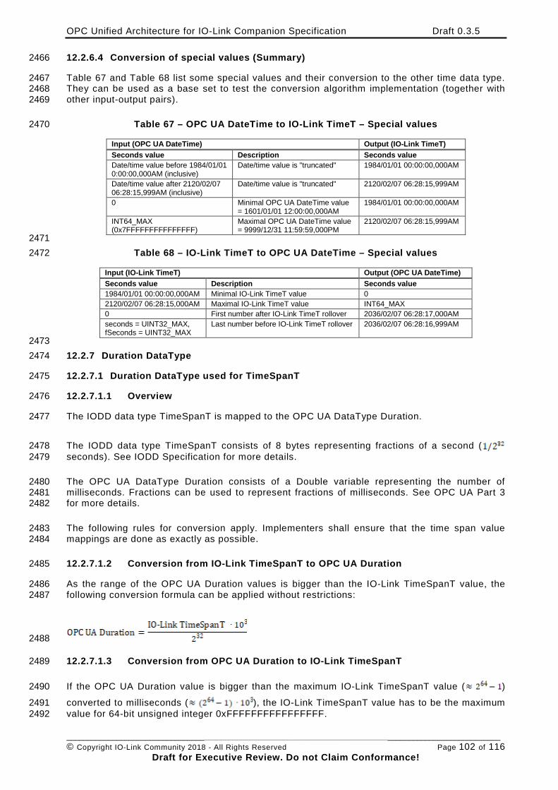
OPC Unified Architecture for IO-Link Companion Specification Draft 0.3.5
________________________________________________________________________________________________________ © Copyright IO-Link Community 2018 - All Rights Reserved Page 102 of 116
Draft for Executive Review. Do not Claim Conformance!
12.2.6.4 Conversion of special values (Summary) 2466
Table 67 and Table 68 list some special values and their conversion to the other time data type. 2467 They can be used as a base set to test the conversion algorithm implementation (together with 2468 other input-output pairs). 2469
Table 67 – OPC UA DateTime to IO-Link TimeT – Special values 2470
Input (OPC UA DateTime) Output (IO-Link TimeT) Seconds value Description Seconds value Date/time value before 1984/01/01 0:00:00,000AM (inclusive)
Date/time value is "truncated" 1984/01/01 00:00:00,000AM
Date/time value after 2120/02/07 06:28:15,999AM (inclusive)
Date/time value is "truncated" 2120/02/07 06:28:15,999AM
0 Minimal OPC UA DateTime value = 1601/01/01 12:00:00,000AM
1984/01/01 00:00:00,000AM
INT64_MAX (0x7FFFFFFFFFFFFFFF)
Maximal OPC UA DateTime value = 9999/12/31 11:59:59,000PM
2120/02/07 06:28:15,999AM
2471 Table 68 – IO-Link TimeT to OPC UA DateTime – Special values 2472
Input (IO-Link TimeT) Output (OPC UA DateTime) Seconds value Description Seconds value 1984/01/01 00:00:00,000AM Minimal IO-Link TimeT value 0 2120/02/07 06:28:15,000AM Maximal IO-Link TimeT value INT64_MAX 0 First number after IO-Link TimeT rollover 2036/02/07 06:28:17,000AM seconds = UINT32_MAX, fSeconds = UINT32_MAX
Last number before IO-Link TimeT rollover 2036/02/07 06:28:16,999AM
2473 12.2.7 Duration DataType 2474
12.2.7.1 Duration DataType used for TimeSpanT 2475
12.2.7.1.1 Overview 2476
The IODD data type TimeSpanT is mapped to the OPC UA DataType Duration. 2477
The IODD data type TimeSpanT consists of 8 bytes representing fractions of a second ( 2478 seconds). See IODD Specification for more details. 2479
The OPC UA DataType Duration consists of a Double variable representing the number of 2480 milliseconds. Fractions can be used to represent fractions of milliseconds. See OPC UA Part 3 2481 for more details. 2482
The following rules for conversion apply. Implementers shall ensure that the time span value 2483 mappings are done as exactly as possible. 2484
12.2.7.1.2 Conversion from IO-Link TimeSpanT to OPC UA Duration 2485
As the range of the OPC UA Duration values is bigger than the IO-Link TimeSpanT value, the 2486 following conversion formula can be applied without restrictions: 2487
2488
12.2.7.1.3 Conversion from OPC UA Duration to IO-Link TimeSpanT 2489
If the OPC UA Duration value is bigger than the maximum IO-Link TimeSpanT value ( ) 2490
converted to milliseconds ( ), the IO-Link TimeSpanT value has to be the maximum 2491 value for 64-bit unsigned integer 0xFFFFFFFFFFFFFFFF. 2492
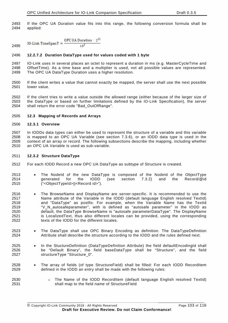
OPC Unified Architecture for IO-Link Companion Specification Draft 0.3.5
________________________________________________________________________________________________________ © Copyright IO-Link Community 2018 - All Rights Reserved Page 103 of 116
Draft for Executive Review. Do not Claim Conformance!
If the OPC UA Duration value fits into this range, the following conversion formula shall be 2493 applied: 2494
2495
12.2.7.2 Duration DataType used for values coded with 1 byte 2496
IO-Link uses in several places an octet to represent a duration in ms (e.g. MasterCycleTime and 2497 OffsetTime). As a time base and a multiplier is used, not all possible values are represented. 2498 The OPC UA DataType Duration uses a higher resolution. 2499
If the client writes a value that cannot exactly be mapped, the server shall use the next possible 2500 lower value. 2501
If the client tries to write a value outside the allowed range (either because of the larger size of 2502 the DataType or based on further limitations defined by the IO-Link Specification), the server 2503 shall return the error code “Bad_OutOfRange”. 2504
12.3 Mapping of Records and Arrays 2505
12.3.1 Overview 2506
In IODDs data types can either be used to represent the structure of a variable and this variable 2507 is mapped to an OPC UA Variable (see section 7.3.6), or an IODD data type is used in the 2508 context of an array or record. The following subsections describe the mapping, including whether 2509 an OPC UA Variable is used as sub-variable. 2510
12.3.2 Structure DataType 2511
For each IODD Record a new OPC UA DataType as subtype of Structure is created. 2512
• The NodeId of the new DataType is composed of the NodeId of the ObjectType 2513 generated for the IODD (see section 7.3.2) and the Record/@id 2514 (“<ObjectTypeId>||<Record id>”). 2515
• The BrowseName and DisplayName are server-specific. It is recommended to use the 2516 Name attribute of the Variable in the IODD (default language English resolved TextId) 2517 and “DataType” as postfix. For example, when the Variable Name has the TextId 2518 “V_N_autosafeparameter”, with is defined as “autosafe parameter” in the IODD as 2519 default, the DataType BrowseName is “autosafe parameterDataType”. The DisplayName 2520 is LocalizedText, thus also different locales can be provided, using the corresponding 2521 texts of the IODD for the different locales. 2522
• The DataType shall use OPC Binary Encoding as definition. The DataTypeDefinition 2523 Attribute shall describe the structure according to the IODD and the rules defined next. 2524
• In the StuctureDefinition (DataTypeDefinition Attribute) the field defaultEncodingId shall 2525 be “Default Binary”, the field baseDataType shall be “Structure”, and the field 2526 structureType “Structure_0”. 2527
• The array of fields (of type StructureField) shall be filled: For each IODD RecordItem 2528 defined in the IODD an entry shall be made with the following rules: 2529
o The Name of the IODD RecordItem (default language English resolved TextId) 2530 shall map to the field name of StructureField 2531
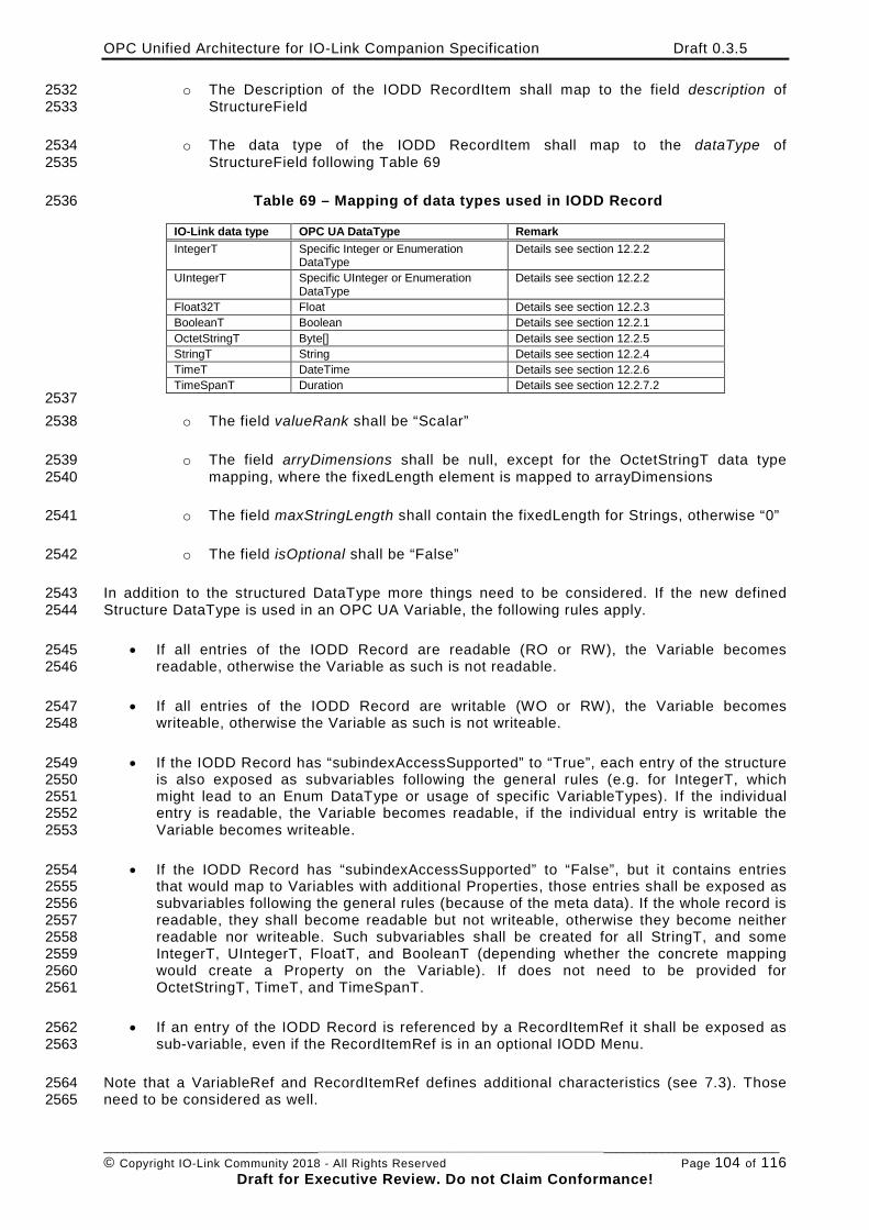
OPC Unified Architecture for IO-Link Companion Specification Draft 0.3.5
________________________________________________________________________________________________________ © Copyright IO-Link Community 2018 - All Rights Reserved Page 104 of 116
Draft for Executive Review. Do not Claim Conformance!
o The Description of the IODD RecordItem shall map to the field description of 2532 StructureField 2533
o The data type of the IODD RecordItem shall map to the dataType of 2534 StructureField following Table 69 2535
Table 69 – Mapping of data types used in IODD Record 2536
IO-Link data type OPC UA DataType Remark IntegerT Specific Integer or Enumeration
DataType Details see section 12.2.2
UIntegerT Specific UInteger or Enumeration DataType
Details see section 12.2.2
Float32T Float Details see section 12.2.3 BooleanT Boolean Details see section 12.2.1 OctetStringT Byte[] Details see section 12.2.5 StringT String Details see section 12.2.4 TimeT DateTime Details see section 12.2.6 TimeSpanT Duration Details see section 12.2.7.2
2537 o The field valueRank shall be “Scalar” 2538
o The field arryDimensions shall be null, except for the OctetStringT data type 2539 mapping, where the fixedLength element is mapped to arrayDimensions 2540
o The field maxStringLength shall contain the fixedLength for Strings, otherwise “0” 2541
o The field isOptional shall be “False” 2542
In addition to the structured DataType more things need to be considered. If the new defined 2543 Structure DataType is used in an OPC UA Variable, the following rules apply. 2544
• If all entries of the IODD Record are readable (RO or RW), the Variable becomes 2545 readable, otherwise the Variable as such is not readable. 2546
• If all entries of the IODD Record are writable (WO or RW), the Variable becomes 2547 writeable, otherwise the Variable as such is not writeable. 2548
• If the IODD Record has “subindexAccessSupported” to “True”, each entry of the structure 2549 is also exposed as subvariables following the general rules (e.g. for IntegerT, which 2550 might lead to an Enum DataType or usage of specific VariableTypes). If the individual 2551 entry is readable, the Variable becomes readable, if the individual entry is writable the 2552 Variable becomes writeable. 2553
• If the IODD Record has “subindexAccessSupported” to “False”, but it contains entries 2554 that would map to Variables with additional Properties, those entries shall be exposed as 2555 subvariables following the general rules (because of the meta data). If the whole record is 2556 readable, they shall become readable but not writeable, otherwise they become neither 2557 readable nor writeable. Such subvariables shall be created for all StringT, and some 2558 IntegerT, UIntegerT, FloatT, and BooleanT (depending whether the concrete mapping 2559 would create a Property on the Variable). If does not need to be provided for 2560 OctetStringT, TimeT, and TimeSpanT. 2561
• If an entry of the IODD Record is referenced by a RecordItemRef it shall be exposed as 2562 sub-variable, even if the RecordItemRef is in an optional IODD Menu. 2563
Note that a VariableRef and RecordItemRef defines additional characteristics (see 7.3). Those 2564 need to be considered as well. 2565
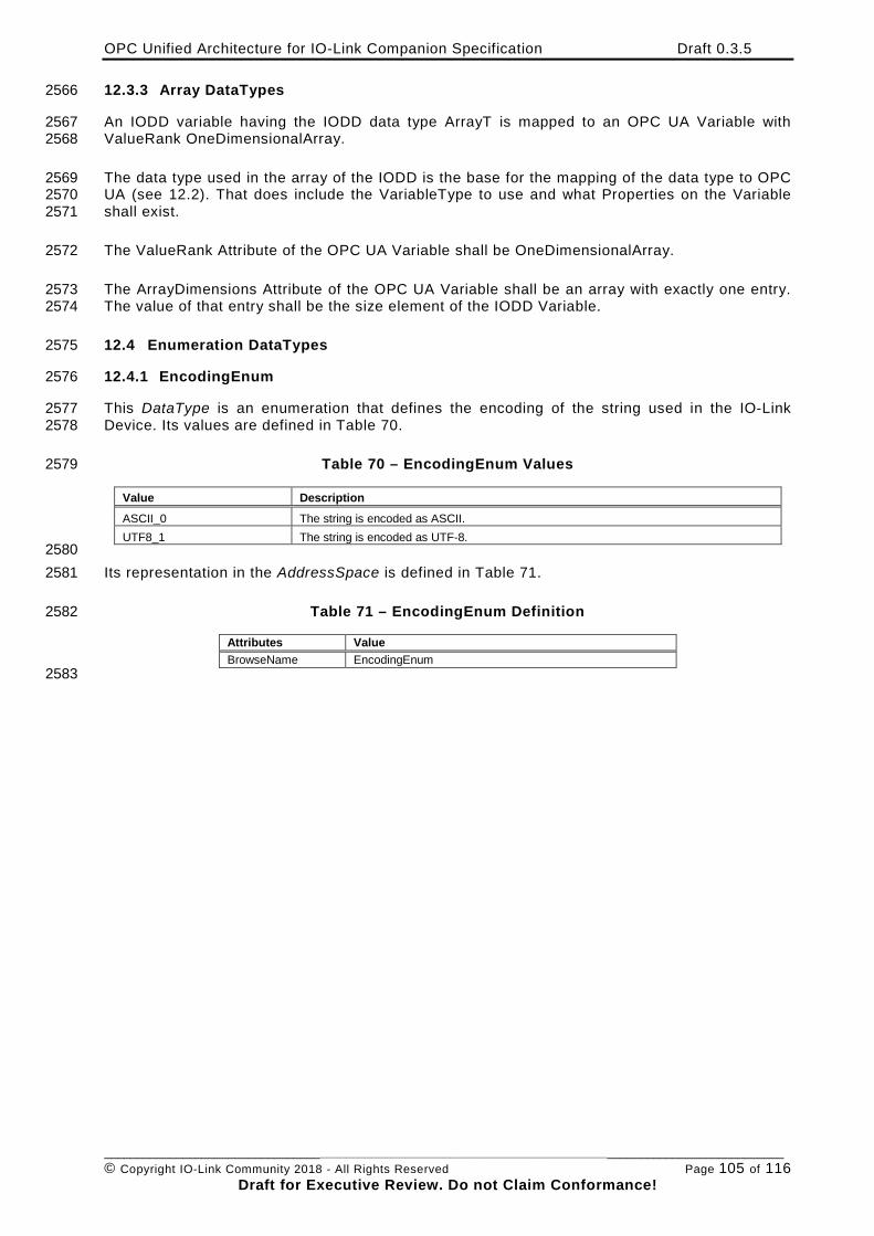
OPC Unified Architecture for IO-Link Companion Specification Draft 0.3.5
________________________________________________________________________________________________________ © Copyright IO-Link Community 2018 - All Rights Reserved Page 105 of 116
Draft for Executive Review. Do not Claim Conformance!
12.3.3 Array DataTypes 2566
An IODD variable having the IODD data type ArrayT is mapped to an OPC UA Variable with 2567 ValueRank OneDimensionalArray. 2568
The data type used in the array of the IODD is the base for the mapping of the data type to OPC 2569 UA (see 12.2). That does include the VariableType to use and what Properties on the Variable 2570 shall exist. 2571
The ValueRank Attribute of the OPC UA Variable shall be OneDimensionalArray. 2572
The ArrayDimensions Attribute of the OPC UA Variable shall be an array with exactly one entry. 2573 The value of that entry shall be the size element of the IODD Variable. 2574
12.4 Enumeration DataTypes 2575
12.4.1 EncodingEnum 2576
This DataType is an enumeration that defines the encoding of the string used in the IO-Link 2577 Device. Its values are defined in Table 70. 2578
Table 70 – EncodingEnum Values 2579
Value Description ASCII_0 The string is encoded as ASCII. UTF8_1 The string is encoded as UTF-8.
2580 Its representation in the AddressSpace is defined in Table 71. 2581
Table 71 – EncodingEnum Definition 2582
Attributes Value BrowseName EncodingEnum
2583
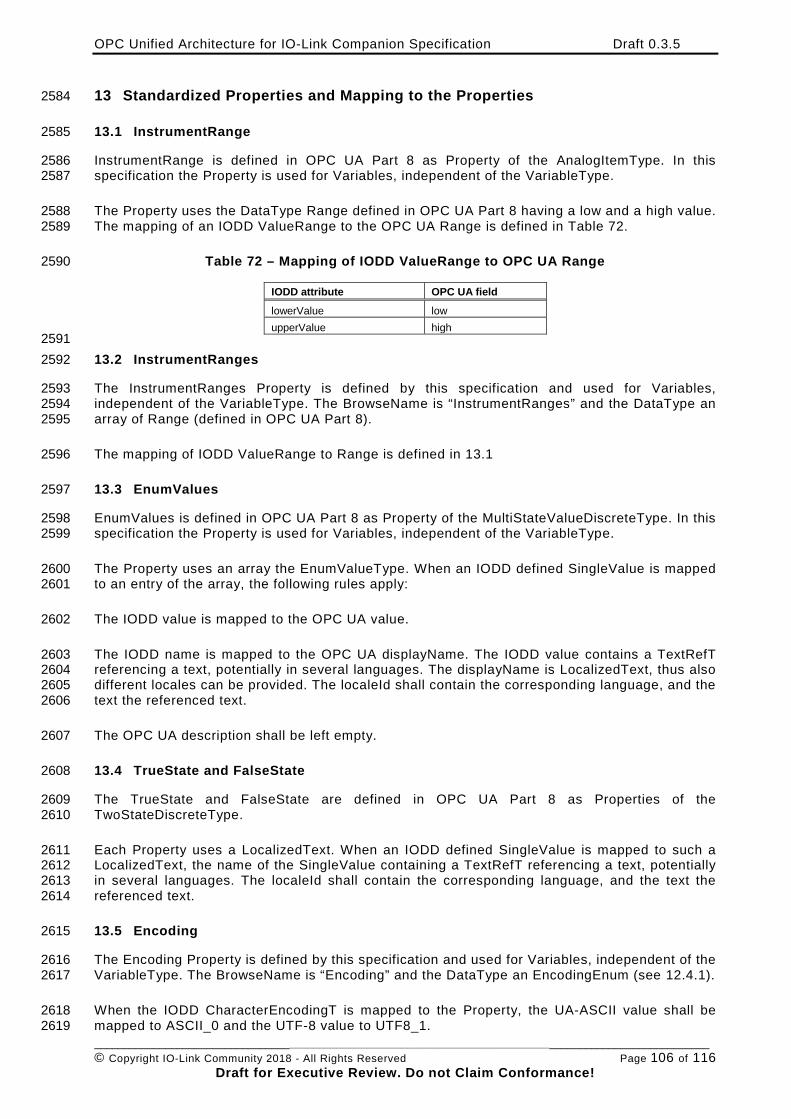
OPC Unified Architecture for IO-Link Companion Specification Draft 0.3.5
________________________________________________________________________________________________________ © Copyright IO-Link Community 2018 - All Rights Reserved Page 106 of 116
Draft for Executive Review. Do not Claim Conformance!
13 Standardized Properties and Mapping to the Properties 2584
13.1 InstrumentRange 2585
InstrumentRange is defined in OPC UA Part 8 as Property of the AnalogItemType. In this 2586 specification the Property is used for Variables, independent of the VariableType. 2587
The Property uses the DataType Range defined in OPC UA Part 8 having a low and a high value. 2588 The mapping of an IODD ValueRange to the OPC UA Range is defined in Table 72. 2589
Table 72 – Mapping of IODD ValueRange to OPC UA Range 2590
IODD attribute OPC UA field lowerValue low upperValue high
2591 13.2 InstrumentRanges 2592
The InstrumentRanges Property is defined by this specification and used for Variables, 2593 independent of the VariableType. The BrowseName is “InstrumentRanges” and the DataType an 2594 array of Range (defined in OPC UA Part 8). 2595
The mapping of IODD ValueRange to Range is defined in 13.1 2596
13.3 EnumValues 2597
EnumValues is defined in OPC UA Part 8 as Property of the MultiStateValueDiscreteType. In this 2598 specification the Property is used for Variables, independent of the VariableType. 2599
The Property uses an array the EnumValueType. When an IODD defined SingleValue is mapped 2600 to an entry of the array, the following rules apply: 2601
The IODD value is mapped to the OPC UA value. 2602
The IODD name is mapped to the OPC UA displayName. The IODD value contains a TextRefT 2603 referencing a text, potentially in several languages. The displayName is LocalizedText, thus also 2604 different locales can be provided. The localeId shall contain the corresponding language, and the 2605 text the referenced text. 2606
The OPC UA description shall be left empty. 2607
13.4 TrueState and FalseState 2608
The TrueState and FalseState are defined in OPC UA Part 8 as Properties of the 2609 TwoStateDiscreteType. 2610
Each Property uses a LocalizedText. When an IODD defined SingleValue is mapped to such a 2611 LocalizedText, the name of the SingleValue containing a TextRefT referencing a text, potentially 2612 in several languages. The localeId shall contain the corresponding language, and the text the 2613 referenced text. 2614
13.5 Encoding 2615
The Encoding Property is defined by this specification and used for Variables, independent of the 2616 VariableType. The BrowseName is “Encoding” and the DataType an EncodingEnum (see 12.4.1). 2617
When the IODD CharacterEncodingT is mapped to the Property, the UA-ASCII value shall be 2618 mapped to ASCII_0 and the UTF-8 value to UTF8_1. 2619
OPC Unified Architecture for IO-Link Companion Specification Draft 0.3.5
________________________________________________________________________________________________________ © Copyright IO-Link Community 2018 - All Rights Reserved Page 107 of 116
Draft for Executive Review. Do not Claim Conformance!
13.6 DisplayFormat 2620
The DisplayFormat Property is defined by this specification and used for Variables, independent 2621 of the VariableType. The BrowseName is “DisplayFormat” and the DataType a String. It contains 2622 the String as defined in the IODD as displayFormat. 2623
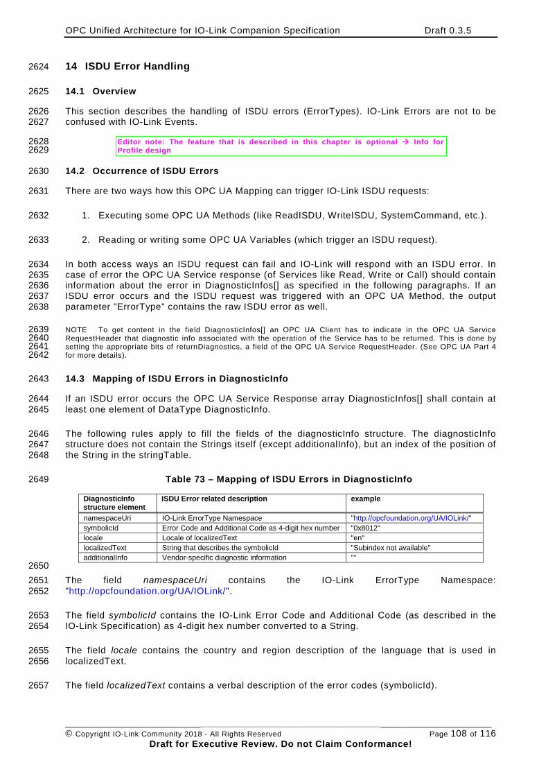
OPC Unified Architecture for IO-Link Companion Specification Draft 0.3.5
________________________________________________________________________________________________________ © Copyright IO-Link Community 2018 - All Rights Reserved Page 108 of 116
Draft for Executive Review. Do not Claim Conformance!
14 ISDU Error Handling 2624
14.1 Overview 2625
This section describes the handling of ISDU errors (ErrorTypes). IO-Link Errors are not to be 2626 confused with IO-Link Events. 2627
Editor note: The feature that is described in this chapter is optional Info for 2628 Profile design 2629
14.2 Occurrence of ISDU Errors 2630
There are two ways how this OPC UA Mapping can trigger IO-Link ISDU requests: 2631
1. Executing some OPC UA Methods (like ReadISDU, WriteISDU, SystemCommand, etc.). 2632
2. Reading or writing some OPC UA Variables (which trigger an ISDU request). 2633
In both access ways an ISDU request can fail and IO-Link will respond with an ISDU error. In 2634 case of error the OPC UA Service response (of Services like Read, Write or Call) should contain 2635 information about the error in DiagnosticInfos[] as specified in the following paragraphs. If an 2636 ISDU error occurs and the ISDU request was triggered with an OPC UA Method, the output 2637 parameter "ErrorType" contains the raw ISDU error as well. 2638
NOTE To get content in the field DiagnosticInfos[] an OPC UA Client has to indicate in the OPC UA Service 2639 RequestHeader that diagnostic info associated with the operation of the Service has to be returned. This is done by 2640 setting the appropriate bits of returnDiagnostics, a field of the OPC UA Service RequestHeader. (See OPC UA Part 4 2641 for more details). 2642
14.3 Mapping of ISDU Errors in DiagnosticInfo 2643
If an ISDU error occurs the OPC UA Service Response array DiagnosticInfos[] shall contain at 2644 least one element of DataType DiagnosticInfo. 2645
The following rules apply to fill the fields of the diagnosticInfo structure. The diagnosticInfo 2646 structure does not contain the Strings itself (except additionalInfo), but an index of the position of 2647 the String in the stringTable. 2648
Table 73 – Mapping of ISDU Errors in DiagnosticInfo 2649
DiagnosticInfo structure element
ISDU Error related description example
namespaceUri IO-Link ErrorType Namespace "http://opcfoundation.org/UA/IOLink/" symbolicId Error Code and Additional Code as 4-digit hex number "0x8012" locale Locale of localizedText "en" localizedText String that describes the symbolicId "Subindex not available" additionalInfo Vendor-specific diagnostic information ""
2650 The field namespaceUri contains the IO-Link ErrorType Namespace: 2651 "http://opcfoundation.org/UA/IOLink/". 2652
The field symbolicId contains the IO-Link Error Code and Additional Code (as described in the 2653 IO-Link Specification) as 4-digit hex number converted to a String. 2654
The field locale contains the country and region description of the language that is used in 2655 localizedText. 2656
The field localizedText contains a verbal description of the error codes (symbolicId). 2657
OPC Unified Architecture for IO-Link Companion Specification Draft 0.3.5
________________________________________________________________________________________________________ © Copyright IO-Link Community 2018 - All Rights Reserved Page 109 of 116
Draft for Executive Review. Do not Claim Conformance!
Note: This is a String, but not the built-in OPC UA DataType LocalizedText! The content of 2658 localizedText is specified in 14.4. 2659
The content of additionalInfo is specified in 14.4. 2660
14.4 Content of localizedText in DiagnosticInfo 2661
14.4.1 No IODD information available 2662
If the combination of IO-Link Error Code and Additional Code is listed in the IO-Link 2663 Specification, the sever shall use the text of Table C.1 or Table C.2 in column "Incident" as 2664 localizedText. Default locale is "en". Servers may provide vendor-specific translations to other 2665 languages. (In this case they have to adjust the value of locale as well.) 2666
If the combination of IO-Link Error Code and Additional Code is vendor-specific (0x8101 to 2667 0x81FF) no string shall be provided at all. This is indicated by giving stringTable index -1 as 2668 localizedText. 2669
The content of additionalInfo is vendor-specific, but usually an empty string. 2670
14.4.2 IODD information available 2671
If the combination of IO-Link Error Code and Additional Code is listed in the IODD 2672 StandardDefinitions (see IODD Specification), the server shall use text specified there with the 2673 appropriate locale as localizedText. Servers may provide vendor-specific translations to other 2674 languages. (In this case they have to adjust the value of locale as well.) 2675
If the combination of IO-Link Error Code and Additional Code is vendor-specific (0x8101 to 2676 0x81FF) the IODD should contain an entry in its ErrorTypeCollection. 2677
• If the IODD does not contain a corresponding entry in its ErrorTypeCollection no string 2678 shall be provided at all. This is indicated by giving stringTable index -1 as localizedText. 2679
• If the IODD contains a corresponding entry in its ErrorTypeCollection, the localizedText 2680 contains the text referenced by the XML property "Name" of the XML element 2681 "ErrorType". The additionalInfo contains the text referenced by the XML property 2682 "Description" of the XML element "ErrorType", if the description is available. In all other 2683 cases the content of additionalInfo is vendor-specific, but usually an empty string. 2684
As a result of this, the StdErrorTypeRef elements of the ErrorTypeCollection in the IODD might 2685 be ignored by the OPC UA server. 2686
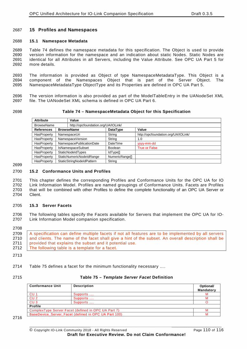
OPC Unified Architecture for IO-Link Companion Specification Draft 0.3.5
________________________________________________________________________________________________________ © Copyright IO-Link Community 2018 - All Rights Reserved Page 110 of 116
Draft for Executive Review. Do not Claim Conformance!
15 Profiles and Namespaces 2687
15.1 Namespace Metadata 2688
Table 74 defines the namespace metadata for this specification. The Object is used to provide 2689 version information for the namespace and an indication about static Nodes. Static Nodes are 2690 identical for all Attributes in all Servers, including the Value Attribute. See OPC UA Part 5 for 2691 more details. 2692
The information is provided as Object of type NamespaceMetadataType. This Object is a 2693 component of the Namespaces Object that is part of the Server Object. The 2694 NamespaceMetadataType ObjectType and its Properties are defined in OPC UA Part 5. 2695
The version information is also provided as part of the ModelTableEntry in the UANodeSet XML 2696 file. The UANodeSet XML schema is defined in OPC UA Part 6. 2697
Table 74 – NamespaceMetadata Object for this Specification 2698
Attribute Value BrowseName http://opcfoundation.org/UA/IOLink/ References BrowseName DataType Value HasProperty NamespaceUri String http://opcfoundation.org/UA/IOLink/ HasProperty NamespaceVersion String 1.0 HasProperty NamespacePublicationDate DateTime yyyy-mm-dd HasProperty IsNamespaceSubset Boolean True or False HasProperty StaticNodeIdTypes IdType[] HasProperty StaticNumericNodeIdRange NumericRange[] HasProperty StaticStringNodeIdPattern String
2699 15.2 Conformance Units and Profiles 2700
This chapter defines the corresponding Profiles and Conformance Units for the OPC UA for IO 2701 Link Information Model. Profiles are named groupings of Conformance Units. Facets are Profiles 2702 that will be combined with other Profiles to define the complete functionality of an OPC UA Server or 2703 Client. 2704
15.3 Server Facets 2705
The following tables specify the Facets available for Servers that implement the OPC UA for IO-2706 Link Information Model companion specification. 2707
2708 A specification can define multiple facets if not all features are to be implemented by all servers 2709 and clients. The name of the facet shall give a hint of the subset. An overall description shall be 2710 provided that explains the subset and it potential use. 2711 The following table is a template for a facet. 2712
2713
Table 75 defines a facet for the minimum functionality necessary …. 2714
Table 75 – Template Server Facet Definition 2715
Conformance Unit Description Optional/ Mandatory
CU 1 Supports …. M CU 2 Supports …. M CU 3 Supports …. O Profile ComplexType Server Facet (defined in OPC UA Part 7) M BaseDevice_Server_Facet (defined in OPC UA Part 100) M 2716
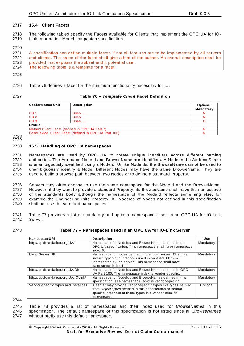
OPC Unified Architecture for IO-Link Companion Specification Draft 0.3.5
________________________________________________________________________________________________________ © Copyright IO-Link Community 2018 - All Rights Reserved Page 111 of 116
Draft for Executive Review. Do not Claim Conformance!
15.4 Client Facets 2717
The following tables specify the Facets available for Clients that implement the OPC UA for IO-2718 Link Information Model companion specification. 2719
2720 A specification can define multiple facets if not all features are to be implemented by all servers 2721 and clients. The name of the facet shall give a hint of the subset. An overall description shall be 2722 provided that explains the subset and it potential use. 2723 The following table is a template for a facet. 2724
2725
Table 76 defines a facet for the minimum functionality necessary for …. 2726
Table 76 – Template Client Facet Definition 2727
Conformance Unit Description Optional/ Mandatory
CU 1 Uses …. M CU 2 Uses …. M CU 3 Uses …. O Profile Method Client Facet (defined in OPC UA Part 7) M BaseDevice_Client_Facet (defined in OPC UA Part 100) M 2728 2729 15.5 Handling of OPC UA namespaces 2730
Namespaces are used by OPC UA to create unique identifiers across different naming 2731 authorities. The Attributes NodeId and BrowseName are identifiers. A Node in the AddressSpace 2732 is unambiguously identified using a NodeId. Unlike NodeIds, the BrowseName cannot be used to 2733 unambiguously identify a Node. Different Nodes may have the same BrowseName. They are 2734 used to build a browse path between two Nodes or to define a standard Property. 2735
Servers may often choose to use the same namespace for the NodeId and the BrowseName. 2736 However, if they want to provide a standard Property, its BrowseName shall have the namespace 2737 of the standards body although the namespace of the NodeId reflects something else, for 2738 example the EngineeringUnits Property. All NodeIds of Nodes not defined in this specification 2739 shall not use the standard namespaces. 2740
Table 77 provides a list of mandatory and optional namespaces used in an OPC UA for IO-Link 2741 Server. 2742
Table 77 – Namespaces used in an OPC UA for IO-Link Server 2743
NamespaceURI Description Use http://opcfoundation.org/UA/ Namespace for NodeIds and BrowseNames defined in the
OPC UA specification. This namespace shall have namespace index 0.
Mandatory
Local Server URI Namespace for nodes defined in the local server. This may include types and instances used in an AutoID Device represented by the server. This namespace shall have namespace index 1.
Mandatory
http://opcfoundation.org/UA/DI/ Namespace for NodeIds and BrowseNames defined in OPC UA Part 100. The namespace index is vendor-specific.
Mandatory
http://opcfoundation.org/UA/IOLink/ Namespace for NodeIds and BrowseNames defined in this specification. The namespace index is vendor-specific.
Mandatory
Vendor-specific types and instances A server may provide vendor-specific types like types derived from ObjectTypes defined in this specification or vendor-specific instances of those types in a vendor-specific namespace.
Optional
2744 Table 78 provides a list of namespaces and their index used for BrowseNames in this 2745 specification. The default namespace of this specification is not listed since all BrowseNames 2746 without prefix use this default namespace. 2747
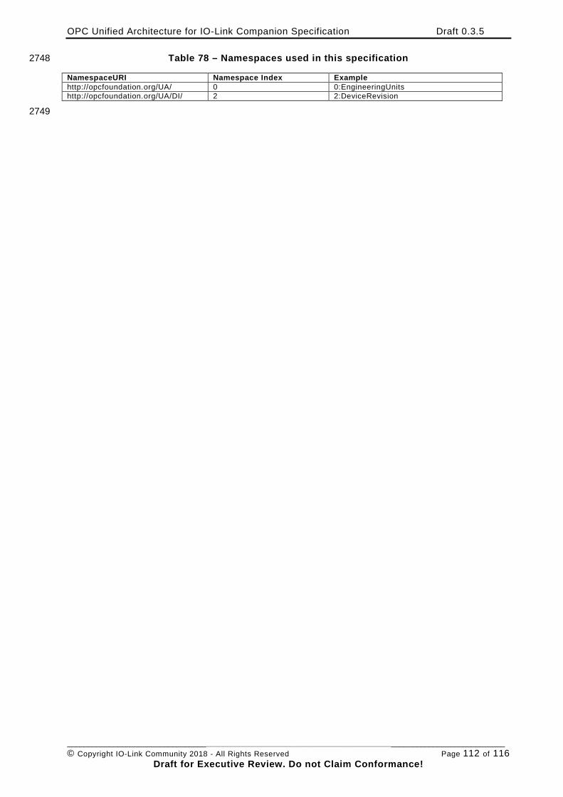
OPC Unified Architecture for IO-Link Companion Specification Draft 0.3.5
________________________________________________________________________________________________________ © Copyright IO-Link Community 2018 - All Rights Reserved Page 112 of 116
Draft for Executive Review. Do not Claim Conformance!
Table 78 – Namespaces used in this specification 2748
NamespaceURI Namespace Index Example http://opcfoundation.org/UA/ 0 0:EngineeringUnits http://opcfoundation.org/UA/DI/ 2 2:DeviceRevision
2749
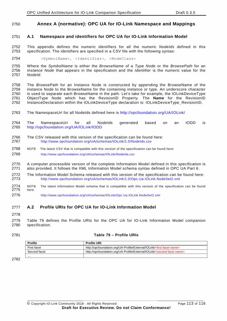
OPC Unified Architecture for IO-Link Companion Specification Draft 0.3.5
________________________________________________________________________________________________________ © Copyright IO-Link Community 2018 - All Rights Reserved Page 113 of 116
Draft for Executive Review. Do not Claim Conformance!
Annex A (normative): OPC UA for IO-Link Namespace and Mappings 2750
A.1 Namespace and identifiers for OPC UA for IO-Link Information Model 2751
This appendix defines the numeric identifiers for all the numeric NodeIds defined in this 2752 specification. The identifiers are specified in a CSV file with the following syntax: 2753
<SymbolName>, <Identifier>, <NodeClass> 2754
Where the SymbolName is either the BrowseName of a Type Node or the BrowsePath for an 2755 Instance Node that appears in the specification and the Identifier is the numeric value for the 2756 NodeId. 2757
The BrowsePath for an Instance Node is constructed by appending the BrowseName of the 2758 instance Node to the BrowseName for the containing instance or type. An underscore character 2759 is used to separate each BrowseName in the path. Let’s take for example, the IOLinkDeviceType 2760 ObjectType Node which has the RevisionID Property. The Name for the RevisionID 2761 InstanceDeclaration within the IOLinkDeviceType declaration is: IOLinkDeviceType_RevisionID. 2762
The NamespaceUri for all NodeIds defined here is http://opcfoundation.org/UA/IOLink/ 2763
The NamespaceUri for all NodeIds generated based on an IODD is 2764 http://opcfoundation.org/UA/IOLink/IODD 2765
The CSV released with this version of the specification can be found here: 2766 http://www.opcfoundation.org/UA/schemas/IOLink/1.0/NodeIds.csv 2767
NOTE The latest CSV that is compatible with this version of the specification can be found here: 2768 http://www.opcfoundation.org/UA/schemas/IOLink/NodeIds.csv 2769
A computer processible version of the complete Information Model defined in this specification is 2770 also provided. It follows the XML Information Model schema syntax defined in OPC UA Part 6. 2771 The Information Model Schema released with this version of the specification can be found here: 2772
http://www.opcfoundation.org/UA/schemas/IOLink/1.0/Opc.Ua.IOLink.NodeSet2.xml 2773
NOTE The latest Information Model schema that is compatible with this version of the specification can be found 2774 here: 2775
http://www.opcfoundation.org/UA/schemas/IOLink/Opc.Ua.IOLink.NodeSet2.xml 2776
A.2 Profile URIs for OPC UA for IO-Link Information Model 2777
2778 Table 79 defines the Profile URIs for the OPC UA for IO-Link Information Model companion 2779 specification. 2780
Table 79 – Profile URIs 2781
Profile Profile URI First facet http://opcfoundation.org/UA-Profile/External/IOLink/<first facet name> Second facet http://opcfoundation.org/UA-Profile/External/IOLink/<second facet name> … 2782
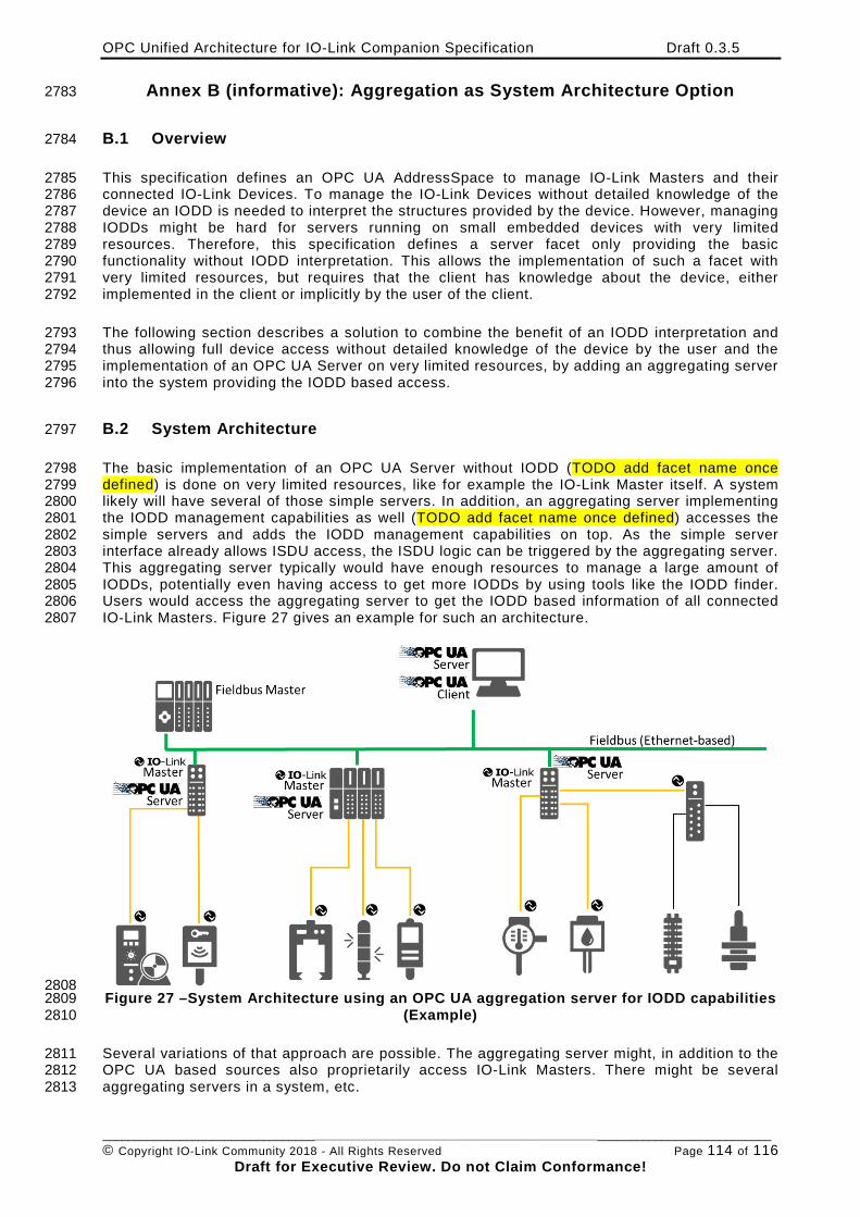
OPC Unified Architecture for IO-Link Companion Specification Draft 0.3.5
________________________________________________________________________________________________________ © Copyright IO-Link Community 2018 - All Rights Reserved Page 114 of 116
Draft for Executive Review. Do not Claim Conformance!
Annex B (informative): Aggregation as System Architecture Option 2783
B.1 Overview 2784
This specification defines an OPC UA AddressSpace to manage IO-Link Masters and their 2785 connected IO-Link Devices. To manage the IO-Link Devices without detailed knowledge of the 2786 device an IODD is needed to interpret the structures provided by the device. However, managing 2787 IODDs might be hard for servers running on small embedded devices with very limited 2788 resources. Therefore, this specification defines a server facet only providing the basic 2789 functionality without IODD interpretation. This allows the implementation of such a facet with 2790 very limited resources, but requires that the client has knowledge about the device, either 2791 implemented in the client or implicitly by the user of the client. 2792
The following section describes a solution to combine the benefit of an IODD interpretation and 2793 thus allowing full device access without detailed knowledge of the device by the user and the 2794 implementation of an OPC UA Server on very limited resources, by adding an aggregating server 2795 into the system providing the IODD based access. 2796
B.2 System Architecture 2797
The basic implementation of an OPC UA Server without IODD (TODO add facet name once 2798 defined) is done on very limited resources, like for example the IO-Link Master itself. A system 2799 likely will have several of those simple servers. In addition, an aggregating server implementing 2800 the IODD management capabilities as well (TODO add facet name once defined) accesses the 2801 simple servers and adds the IODD management capabilities on top. As the simple server 2802 interface already allows ISDU access, the ISDU logic can be triggered by the aggregating server. 2803 This aggregating server typically would have enough resources to manage a large amount of 2804 IODDs, potentially even having access to get more IODDs by using tools like the IODD finder. 2805 Users would access the aggregating server to get the IODD based information of all connected 2806 IO-Link Masters. Figure 27 gives an example for such an architecture. 2807
2808 Figure 27 –System Architecture using an OPC UA aggregation server for IODD capabilities 2809
(Example) 2810
Several variations of that approach are possible. The aggregating server might, in addition to the 2811 OPC UA based sources also proprietarily access IO-Link Masters. There might be several 2812 aggregating servers in a system, etc. 2813
OPC Unified Architecture for IO-Link Companion Specification Draft 0.3.5
________________________________________________________________________________________________________ © Copyright IO-Link Community 2018 - All Rights Reserved Page 115 of 116
Draft for Executive Review. Do not Claim Conformance!
Annex C (normative): EngineeringUnits 2814
C.1 Overview 2815
OPC UA defines a preferred namespace for EngineeringUnits. The mapping of IO-Link unitCode 2816 to OPC UA EngineeringUnits uses the EngineeringUnits of the preferred OPC UA namespace, 2817 when they are also defined. Otherwise, it uses its own namespace. The mapping is defined in a 2818 CSV document. 2819
The CSV released with this version of the specification can be found here: 2820 http://www.opcfoundation.org/UA/schemas/IOLink/1.0/EnineeringUnits.csv 2821
NOTE The latest CSV that is compatible with this version of the specification can be found here: 2822 http://www.opcfoundation.org/UA/schemas/IOLink/EngineeringUnits.csv 2823

Copyright by:
IO-Link Community Haid-und-Neu-Str. 7 76131 Karlsruhe Germany Phone: +49 (0) 721 / 96 58 590 Fax: +49 (0) 721 / 96 58 589 e-mail: [email protected] http://www.io-link.com/