Embed Size (px)
Citation preview
OPEL Combo
Owner�s Manual

OPEL Combo
Operation, Safety, Maintenance

Data specific to your vehiclePlease enter your vehicle�s data here to keep it easily accessible. This information is available in the sections "Service and maintenance" and "Technical data" as well as on the identification plate.
Fuel Designation
Engine oil Grade
Viscosity
Tyre pressure
Tyre size Front Rear
Summer tyres
Winter tyres
Weights Gross vehicle weight rating
� EC kerb weight
= Payload
IntroductionYour vehicle is an intelligent combination of forward-looking technology, impressive safety, environmental friendliness and economy.
It now lies with you to drive your vehicle safely and to see it performs perfectly. This Owner�s Manual provides you with all the necessary information to that end.
Make sure your passengers are aware of the possible risk of accident and injury which may result from improper use of the vehicle.
You must always follow the specific laws of the country in which you are located. These could differ from the information in this Owner�s Manual.
When this Manual refers to a workshop visit, we recommend your Opel Service Partner.
All Opel Service Partners provide first-class service at reasonable prices. Experienced mechanics trained by Opel work according to specific Opel instructions.
The Owner�s Manual, infotainment system instructions and vehicle service and warranty booklet should always be kept ready to hand in the vehicle glove compartment.
Make use of the Owner�s Manual z The "In Brief" section will give you an
initial overview.
z The table of contents at the beginning of the owner�s manual and within the individual chapters will show you where everything is.
z Its index will help you find what you want.
z Yellow arrows in the illustrations serve as points of reference or indicate some action to be performed.
z Black arrows in the illustrations indicate a reaction or a second action to be performed.
z This Owner�s Manual depicts left-hand drive vehicles. Operation is similar for right-hand drive vehicles.
z The Owner�s Manual uses the internal engine codes. The corresponding sales designations are found in the chapter "Technical data".
z Direction references such as left or right, forwards or backwards in the descriptions always indicate the direction of travel.
Symbols6 Continue reading on next page.
3 signifies equipment not fitted to all vehicles (model variants, engine options, models specific to one country, optional equipment, Genuine Opel Parts and Accessories).
Page references are indicated with 3 . 3 means "see page".
9 Danger, 9 Warning, Caution
We wish you many hours of pleasurable driving
Adam Opel GmbH
9 Danger
Text marked 9 Danger provides information on risk of endangering life. Failure to comply with the instructions could endanger life.
9 Warning
Text marked 9 Warning provides information on risk of accident or injury. Failure to comply with the instructions could lead to injury.
Caution
Text marked Caution provides information on possible damage to the vehicle Failure to comply with the instructions could lead to vehicle damage.

Contents In Brief ........................................................ 2Keys, doors, windows ............................. 20Seats, Interior .......................................... 38Instruments ............................................. 66Lighting ................................................... 84Infotainment system .............................. 90Climate control ....................................... 92Driving and operation ......................... 100Self-help, vehicle care .......................... 128Opel Service, maintenance .................. 164Technical data ..................................... 182Index ...................................................... 198
2 In Brief
In Brief
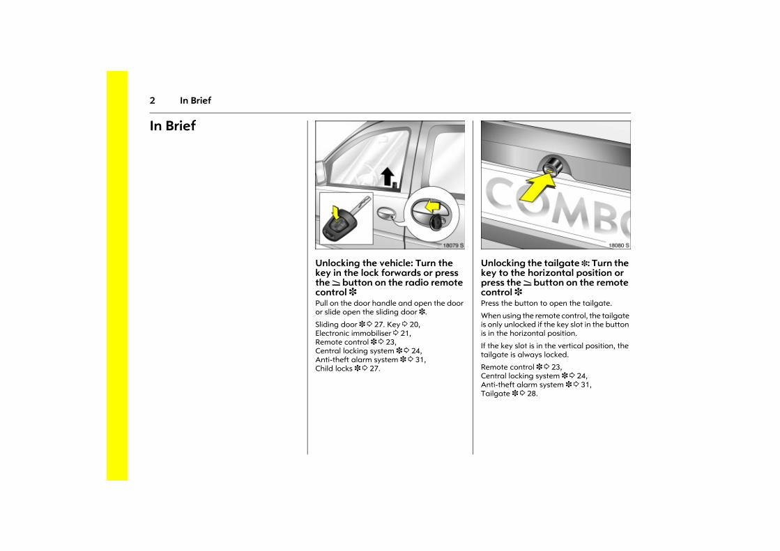
Picture no: 18079s.tifUnlocking the vehicle: Turn the key in the lock forwards or press the q button on the radio remote control 3 Pull on the door handle and open the door or slide open the sliding door 3.
Sliding door 3 3 27. Key 3 20, Electronic immobiliser 3 21, Remote control 3 3 23, Central locking system 3 3 24, Anti-theft alarm system 3 3 31, Child locks 3 3 27.
Picture no: 18080s.tifUnlocking the tailgate 3: Turn the key to the horizontal position or press the q button on the remote control 3 Press the button to open the tailgate.
When using the remote control, the tailgate is only unlocked if the key slot in the button is in the horizontal position.
If the key slot is in the vertical position, the tailgate is always locked.
Remote control 3 3 23, Central locking system 3 3 24, Anti-theft alarm system 3 3 31, Tailgate 3 3 28.
3In Brief
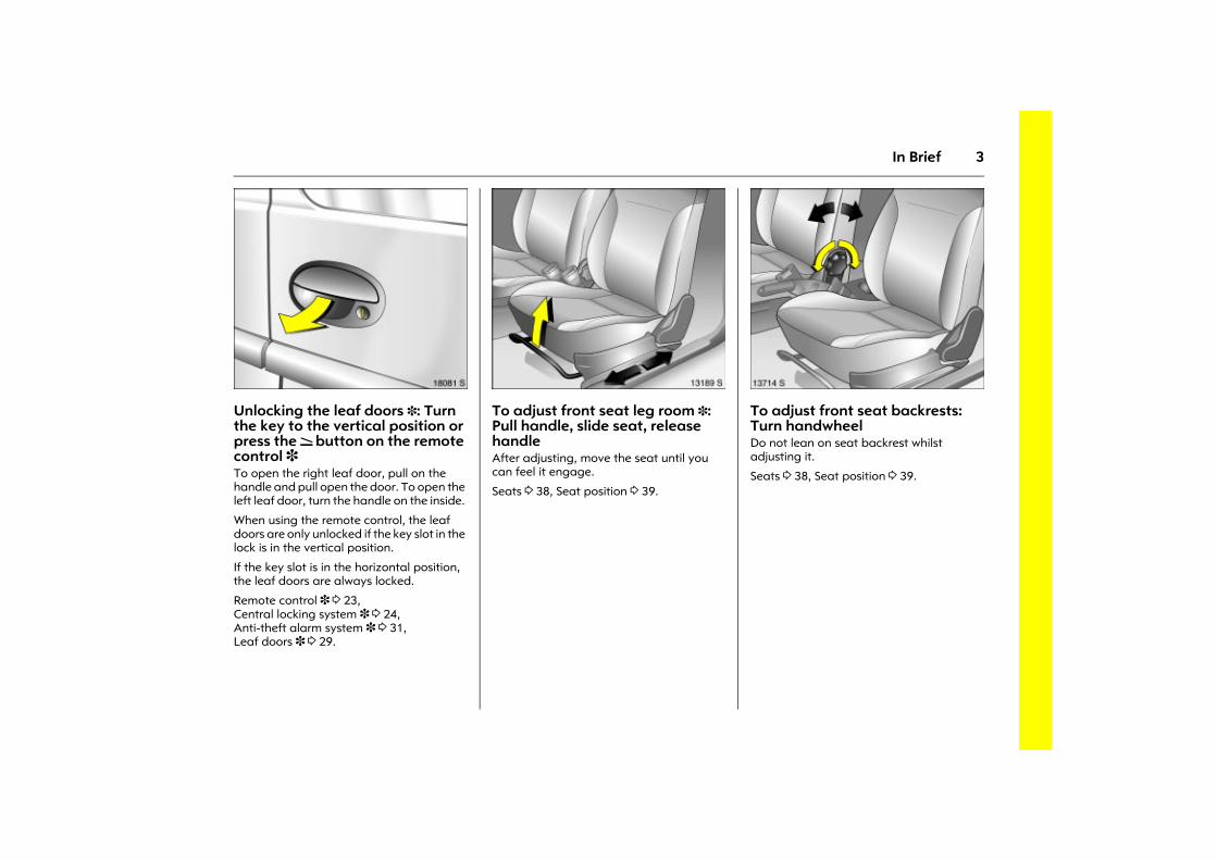
Picture no: 18081s.tifUnlocking the leaf doors 3: Turn the key to the vertical position or press the q button on the remote control 3 To open the right leaf door, pull on the handle and pull open the door. To open the left leaf door, turn the handle on the inside.
When using the remote control, the leaf doors are only unlocked if the key slot in the lock is in the vertical position.
If the key slot is in the horizontal position, the leaf doors are always locked.
Remote control 3 3 23, Central locking system 3 3 24, Anti-theft alarm system 3 3 31, Leaf doors 3 3 29.
Picture no: 13189s.tifTo adjust front seat leg room 3: Pull handle, slide seat, release handle After adjusting, move the seat until you can feel it engage.
Seats 3 38, Seat position 3 39.
Picture no: 13714s.tifTo adjust front seat backrests: Turn handwheel Do not lean on seat backrest whilst adjusting it.
Seats 3 38, Seat position 3 39.
4 In Brief
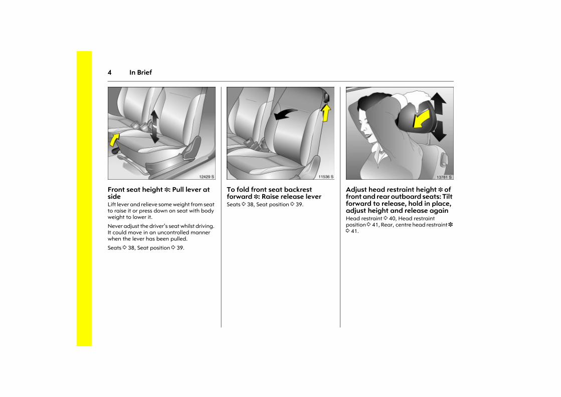
Picture no: 12429s.tifFront seat height 3: Pull lever at side Lift lever and relieve some weight from seat to raise it or press down on seat with body weight to lower it.
Never adjust the driver�s seat whilst driving. It could move in an uncontrolled manner when the lever has been pulled.
Seats 3 38, Seat position 3 39.
Picture no: 11536s.tifTo fold front seat backrest forward 3: Raise release lever Seats 3 38, Seat position 3 39.
Picture no: 13781s.tifAdjust head restraint height 3 of front and rear outboard seats: Tilt forward to release, hold in place, adjust height and release again Head restraint 3 40, Head restraint position 3 41, Rear, centre head restraint 3 3 41.
5In Brief
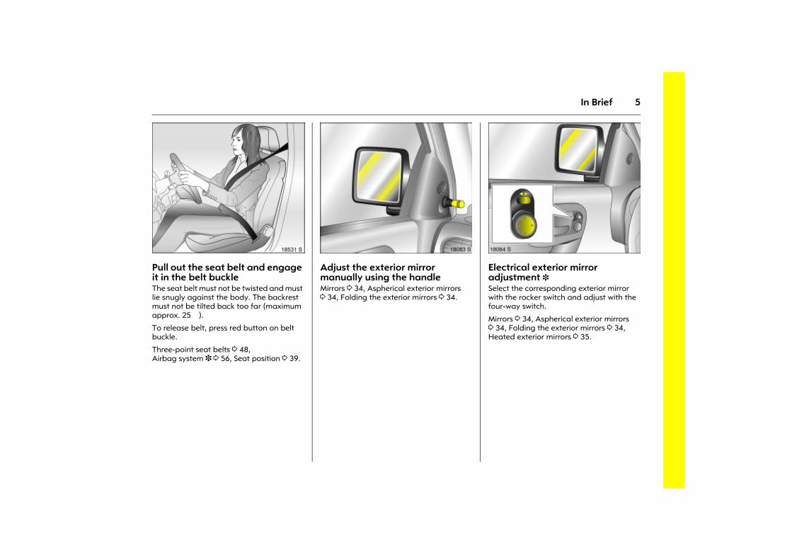
Picture no: 18531s.tifPull out the seat belt and engage it in the belt buckle The seat belt must not be twisted and must lie snugly against the body. The backrest must not be tilted back too far (maximum approx. 25�).
To release belt, press red button on belt buckle.
Three-point seat belts 3 48, Airbag system 3 3 56, Seat position 3 39.
Picture no: 18083s.tifAdjust the exterior mirror manually using the handle Mirrors 3 34, Aspherical exterior mirrors 3 34, Folding the exterior mirrors 3 34.
Picture no: 18084s.tifElectrical exterior mirror adjustment 3 Select the corresponding exterior mirror with the rocker switch and adjust with the four-way switch.
Mirrors 3 34, Aspherical exterior mirrors 3 34, Folding the exterior mirrors 3 34, Heated exterior mirrors 3 35.
6 In Brief
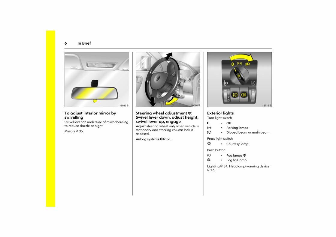
Picture no: 18082s.tifTo adjust interior mirror by swivelling Swivel lever on underside of mirror housing to reduce dazzle at night.
Mirrors 3 35.
Picture no: 18086s.tifSteering wheel adjustment 3: Swivel lever down, adjust height, swivel lever up, engage Adjust steering wheel only when vehicle is stationary and steering column lock is released.
Airbag systems 3 3 56.
Picture no: 13715s.tifExterior lights Turn light switch
Press light switch
Push button
Lighting 3 84, Headlamp-warning device 3 17.
7 = Off8 = Parking lamps9 = Dipped beam or main beam
0 = Courtesy lamp
> = Fog lamps 3 r = Fog tail lamp
7In Brief
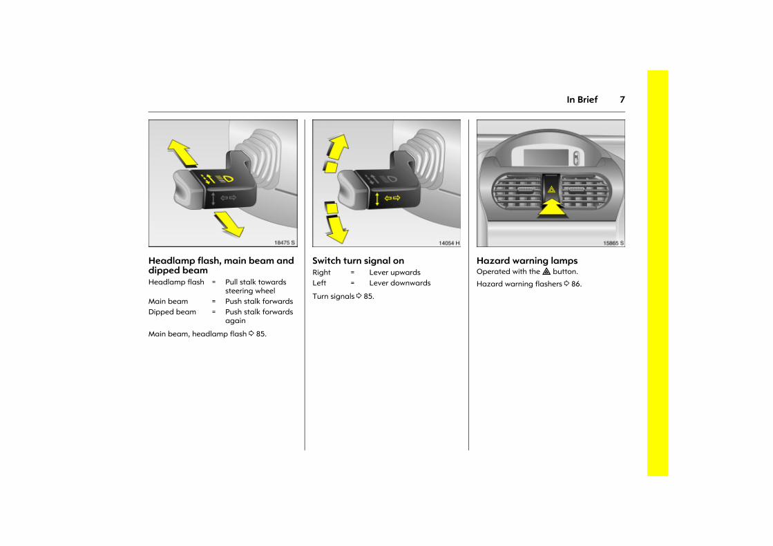
Picture no: 18475s.tifHeadlamp flash, main beam and dipped beam
Main beam, headlamp flash 3 85.
Picture no: 14054h.tifSwitch turn signal on
Turn signals 3 85.
Picture no: 15865s.tifHazard warning lamps Operated with the ¨ button.
Hazard warning flashers 3 86. Headlamp flash = Pull stalk towards steering wheel
Main beam = Push stalk forwardsDipped beam = Push stalk forwards
again
Right = Lever upwardsLeft = Lever downwards
8 In Brief
9In Brief
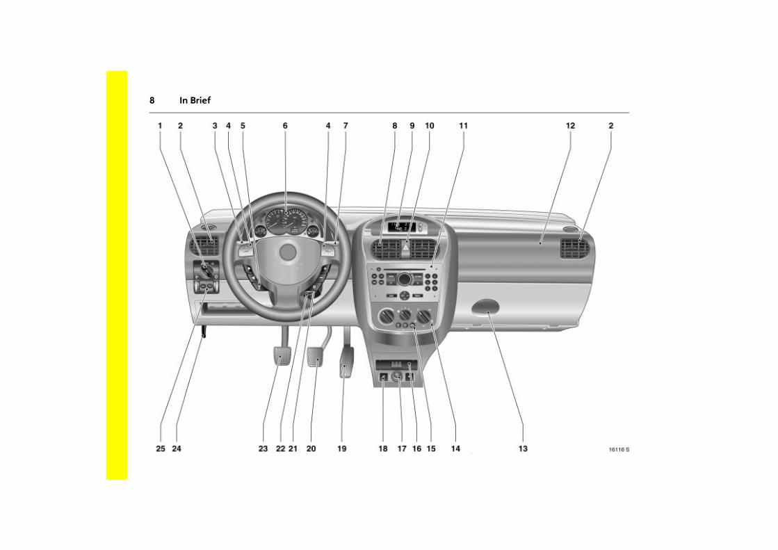
Page1 Light switch .......................... 3 6, 3 84
2 Side air vents ................................ 3 93
3 Turn signals, headlamp flash,dipped beam, main beam .. 3 6, 3 84
4 Horn ...............................................3 13
5 Steering wheel remote control 3 .3 90
6 Instruments ................................... 3 66
7 Windscreen wipers,windscreen washer system,rear window washer system 3 .....3 82
8 Centre air vents .............................3 93
9 Display 3 for time, date,outside temperature,infotainment system 3 ................ 3 77
Page10 Hazard warning lamps ................. 3 7
LED for anti-theft alarm system 33 32
11 Infotainment system 3 ................ 3 90
12 Front passenger airbag 3 ........... 3 56
13 Glove compartment ..................... 3 63
14 Heating and ventilation system . 3 92
15 Air conditioning system 3 ........... 3 96 Heated rear window 3 ....... 3 14, 3 37
Air recirculation system 3 ............ 3 97
16 Ashtray 3 ...................................... 3 62
17 Accessory socket orcigarette lighter ........................... 3 61
18 Seat heating 3 ............................. 3 40Fuel selection switch (natural gas/petrol) 3 ................ 3 113
19 Accelerator pedal .......... 3 106, 3 108
Page20 Brake pedal .................... 3 106, 3 118
21 Ignition switch with steering wheel lock ...................... 3 16
22 Steering wheel adjustment 3 ....... 3 6
23 Clutch pedal 3 ........................... 3 106
24 Bonnet release lever ................... 3 128
25 Headlamp range adjustment 3 .. 3 87Fog tail lamp ................................ 3 86Fog lamps 3 ................................. 3 86Instrument illumination ............... 3 87
10 In Brief
11In Brief
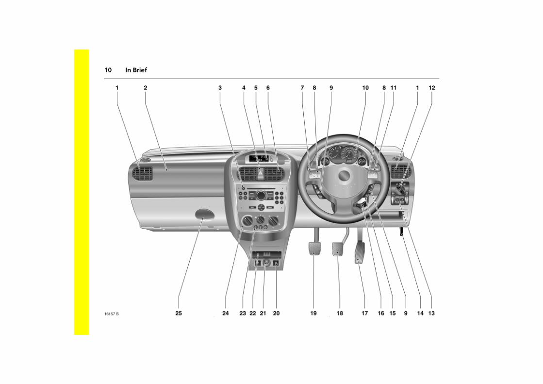
Page1 Side air vents ................................ 3 93
2 Front passenger airbag 3 ........... 3 56
3 Infotainment system 3 ................ 3 90
4 Hazard warning lamps .................. 3 7LED for anti-theft alarm system 3 .............................3 32
5 Display 3 for time, date,outside temperature,infotainment system 3 ................ 3 77
6 Centre air vents .............................3 93
7 Turn signals, headlamp flash,dipped beam, main beam .. 3 6, 3 84
8 Horn ...............................................3 13
9 Steering wheel remote control 3 .3 90
10 Instruments ................................... 3 66
Page11 Windscreen wipers,
windscreen washer system,rear window washer system 3 .....3 82
12 Light switch ........................... 3 6, 3 84
13 Headlamp range adjustment 3 .. 3 87Fog tail lamp ................................ 3 86Fog lamps 3 ................................. 3 86Instrument illumination ............... 3 87
14 Bonnet release lever ................... 3 128
15 Ignition switch with steering wheel lock ...................... 3 16
16 Steering wheel adjustment 3 ........ 3 6
17 Accelerator pedal .......... 3 106, 3 108
18 Brake pedal .................... 3 106, 3 118
19 Clutch pedal 3 ........................... 3 106
Page20 Seat heating 3 ............................. 3 40
Fuel selection switch (natural gas/petrol) 3 ................ 3 113
21 Accessory socket orcigarette lighter ........................... 3 61
22 Ashtray 3 ...................................... 3 62
23 Air conditioning system 3 ........... 3 96 Heated rear window 3 ....... 3 14, 3 37
Air recirculation system 3 ............ 3 97
24 Heating and ventilation system . 3 92
25 Glove compartment .................... 3 63
12 In Brief
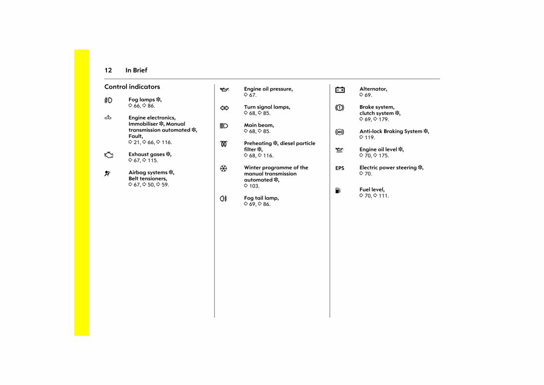
Control indicators
> Fog lamps 3, 3 66, 3 86.
A
Engine electronics, Immobiliser 3, Manual transmission automated 3, Fault, 3 21, 3 66, 3 116.
Z Exhaust gases 3,3 67, 3 115.
v Airbag systems 3,Belt tensioners, 3 67, 3 50, 3 59.
I Engine oil pressure, 3 67.
O Turn signal lamps, 3 68, 3 85.
C Main beam, 3 68, 3 85.
! Preheating 3, diesel particle filter 3,3 68, 3 116.
T Winter programme of the manual transmission automated 3, 3 103.
r Fog tail lamp, 3 69, 3 86.
p Alternator, 3 69.
R Brake system,clutch system 3, 3 69, 3 179.
u Anti-lock Braking System 3, 3 119.
S Engine oil level 3, 3 70, 3 175.
EPS Electric power steering 3, 3 70.
Y Fuel level, 3 70, 3 111.
13In Brief
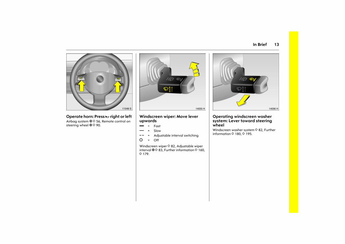
Picture no: 11548s.tifOperate horn: Press j right or left Airbag system 3 3 56, Remote control on steering wheel 3 3 90.
Picture no: 14055h.tifWindscreen wiper: Move lever upwards
Windscreen wiper 3 82, Adjustable wiper interval 3 3 83, Further information 3 160, 3 179.
Picture no: 14056h.tifOperating windscreen washer system: Lever toward steering wheel Windscreen washer system 3 82, Further information 3 180, 3 195.
& = Fast% = Slow $ = Adjustable interval switching§ = Off
14 In Brief
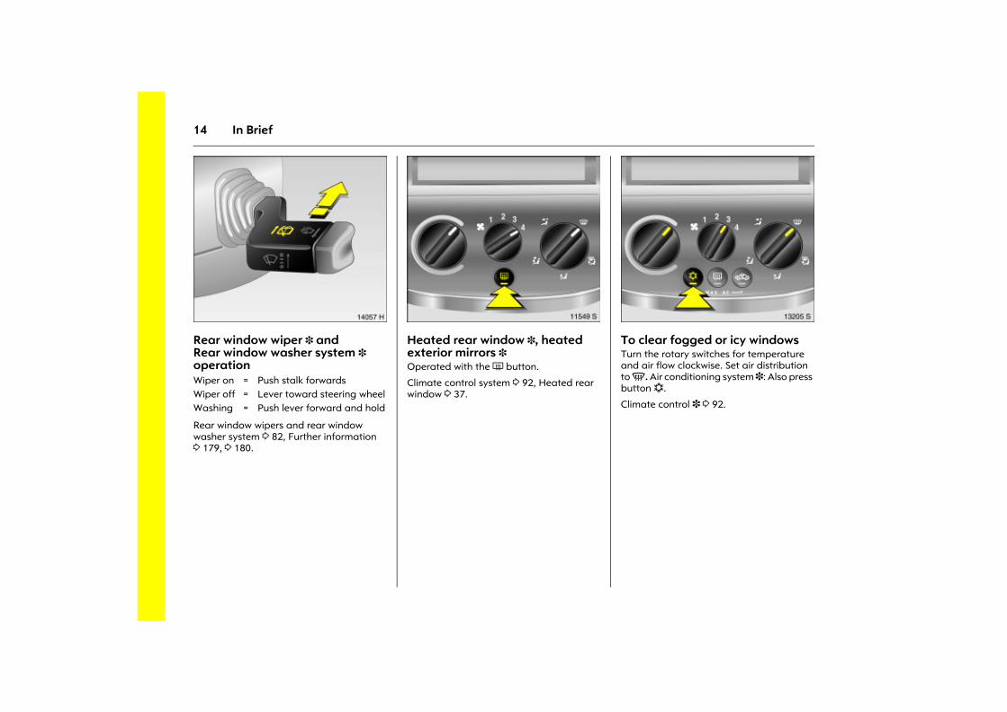
Picture no: 14057h.tifRear window wiper 3 andRear window washer system 3 operation
Rear window wipers and rear window washer system 3 82, Further information 3 179, 3 180.
Picture no: 11549s.tifHeated rear window 3, heated exterior mirrors 3 Operated with the Ü button.
Climate control system 3 92, Heated rear window 3 37.
Picture no: 13205s.tifTo clear fogged or icy windows Turn the rotary switches for temperature and air flow clockwise. Set air distribution to V. Air conditioning system 3: Also press button n.
Climate control 3 3 92.
Wiper on = Push stalk forwardsWiper off = Lever toward steering wheelWashing = Push lever forward and hold
15In Brief
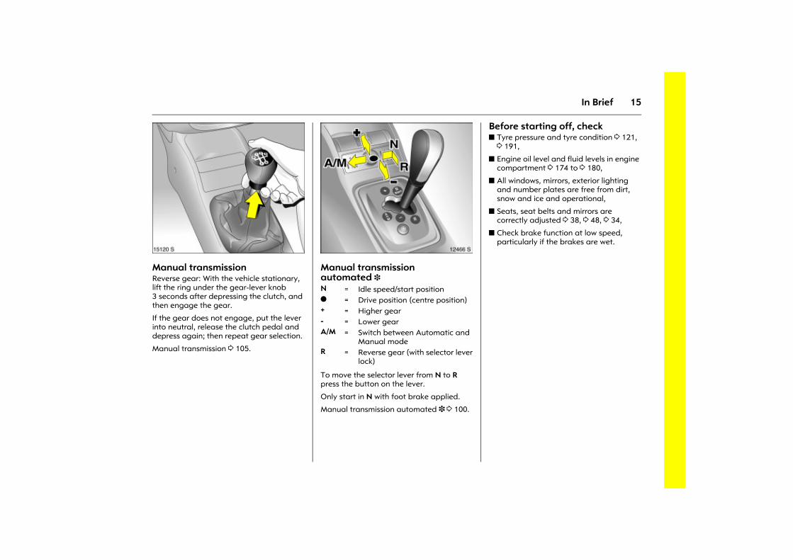
Picture no: 15120s.tifManual transmission Reverse gear: With the vehicle stationary, lift the ring under the gear-lever knob 3 seconds after depressing the clutch, and then engage the gear.
If the gear does not engage, put the lever into neutral, release the clutch pedal and depress again; then repeat gear selection.
Manual transmission 3 105.
Picture no: 12466s.tifManual transmission automated 3
To move the selector lever from N to R press the button on the lever.
Only start in N with foot brake applied.
Manual transmission automated 3 3 100.
Before starting off, check z Tyre pressure and tyre condition 3 121,
3 191,
z Engine oil level and fluid levels in engine compartment 3 174 to 3 180,
z All windows, mirrors, exterior lighting and number plates are free from dirt, snow and ice and operational,
z Seats, seat belts and mirrors are correctly adjusted 3 38, 3 48, 3 34,
z Check brake function at low speed, particularly if the brakes are wet.
N = Idle speed/start positiono = Drive position (centre position) + = Higher gear- = Lower gearA/M = Switch between Automatic and
Manual modeR = Reverse gear (with selector lever
lock)
16 In Brief
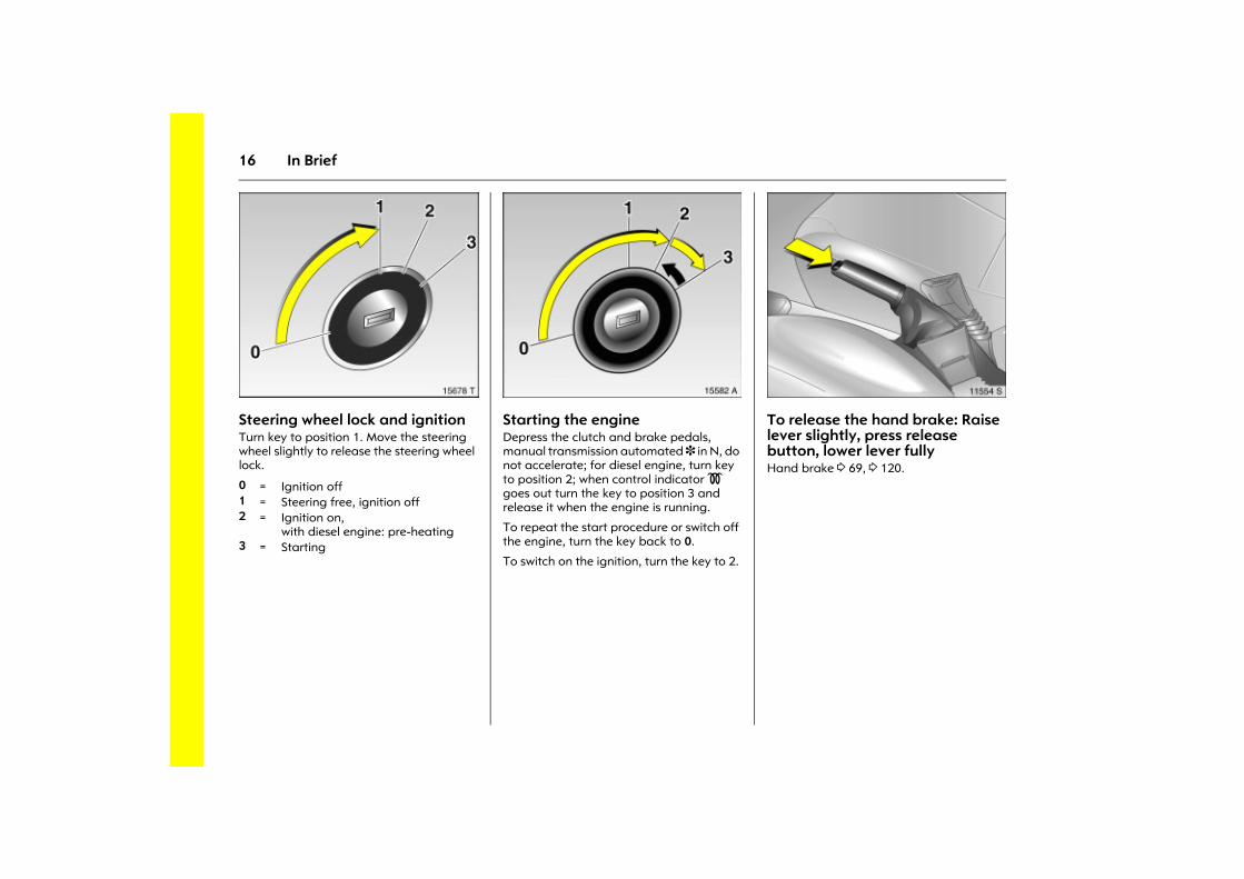
Picture no: 15678t.tifSteering wheel lock and ignitionTurn key to position 1. Move the steering wheel slightly to release the steering wheel lock.
Picture no: 15582a.tifStarting the engine Depress the clutch and brake pedals, manual transmission automated 3 in N, do not accelerate; for diesel engine, turn key to position 2; when control indicator ! goes out turn the key to position 3 and release it when the engine is running.
To repeat the start procedure or switch off the engine, turn the key back to 0.
To switch on the ignition, turn the key to 2.
Picture no: 11554s.tifTo release the hand brake: Raise lever slightly, press release button, lower lever fully Hand brake 3 69, 3 120.
0 = Ignition off1 = Steering free, ignition off2 = Ignition on,
with diesel engine: pre-heating 3 = Starting
17In Brief
Parking the vehicle z Always apply handbrake firmly without
operating the release button, and apply as firmly as possible on a downhill or uphill slope.
z Switch off the engine and ignition by turning the ignition key to 0 and removing it. Turn the steering wheel until you can feel its lock engage (anti-theft protection).
On vehicles with manual transmission automated 3, control indicator R flashes for a few seconds after the ignition is switched off if the hand brake has not been applied.
z If the vehicle is parked on a level surface or an uphill slope, with a manual gearbox select first gear or with manual transmission automated 3 move the selector lever to the centre position before switching off the ignition. Also turn the front wheels away from the kerb if the vehicle is on an uphill slope.
If the vehicle is on a downhill slope, with manual gearbox or manual transmission automated 3 select reverse gear before switching off the ignition. Also turn the front wheels towards the kerb.
z Lock the vehicle with the key in the lock or the p button on the remote control.
Activate the anti-theft locking system 3 and anti-theft alarm system 3 by pressing the p button twice.
Advice when parkingz Do not park vehicle on easily ignitable
surfaces as the hot exhaust system temperatures could cause the surface to ignite.
z Close windows.
z The engine cooling fans may run after the engine has been switched off, 3 174.
Locking doors 3 22, Remote control 3 3 23, Central locking system 3 3 24, Anti-theft alarm system 3 3 31, Vehicle decommissioning 3 181.
Interesting functions
18 In Brief
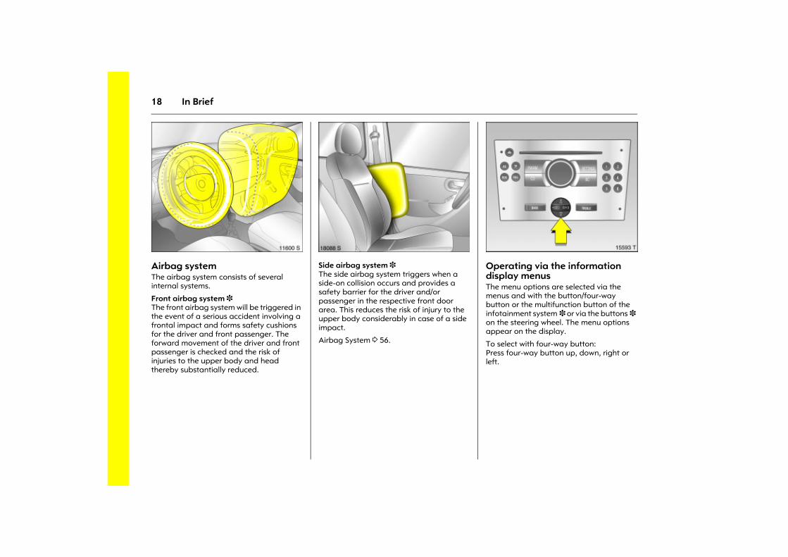
Picture no: 11600s.tifAirbag system The airbag system consists of several internal systems.
Front airbag system 3 The front airbag system will be triggered in the event of a serious accident involving a frontal impact and forms safety cushions for the driver and front passenger. The forward movement of the driver and front passenger is checked and the risk of injuries to the upper body and head thereby substantially reduced.
Picture no: 18088s.tifSide airbag system 3 The side airbag system triggers when a side-on collision occurs and provides a safety barrier for the driver and/or passenger in the respective front door area. This reduces the risk of injury to the upper body considerably in case of a side impact.
Airbag System 3 56.
Picture no: 15593t.tifOperating via the information display menus The menu options are selected via the menus and with the button/four-way button or the multifunction button of the infotainment system 3 or via the buttons 3 on the steering wheel. The menu options appear on the display.
To select with four-way button: Press four-way button up, down, right or left.
19In Brief
Picture no: 14034s.tifSelecting with the multifunction button (adjuster wheel via the four-way rocker switch 3 78): Press and turn multifunction button.
To exit a menu, turn the multifunction button left or right to Return or Main and select.
To select with steering wheel buttons 3: Select menu options via the menus using the buttons.
Information display 3 77.
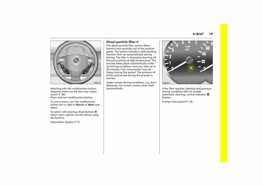
Diesel particle filter 3 The diesel particle filter system filters harmful soot particles out of the exhaust gases. The system includes a self-cleaning function that run automatically during driving. The filter is cleaned by burning off the soot particles at high temperature. This process takes place automatically under set driving conditions and may take up to 25 minutes. Fuel consumption may be higher during this period. The emission of smells and smoke during this process is normal.
Under certain driving conditions, e.g. short distances, the system cannot clean itself automatically.
Picture no: 18528s.tifIf the filter requires cleaning and previous driving conditions did not enable automatic cleaning, control indicator ! flashes.
Further instructions 3 116.
20 Keys, doors, windows
Keys, doors,windows
Replacement keys The key number is specified in the Car Pass 3.
The key is part of the electronic immobiliser.
Locks 3 22, 3 162.
Picture no: 15760t.tifKey with retractable key blade 3 Press button to extend. To retract, press button and audibly engage key blade.
Car Pass The Car Pass contains safety-related vehicle data and should therefore be kept in a safe place.
When the car is taken to a workshop, the Car Pass data is needed in order to perform certain operations.
Replacement keys ............................... 20 Key with retractable key blade 3 ...... 20 Car Pass................................................ 20 Electronic immobiliser.......................... 21 Mechanical unlocking or locking of
individual doors................................. 22 Remote control 3................................. 23 Central locking system 3 .................... 24 Fault in the remote control ................. 26 Malfunction in central locking system 26 Sliding doors 3..................................... 27 Child safety locks 3 ............................. 27 Tailgate 3 ............................................ 28 Leaf doors 3 ........................................ 29 Anti-theft alarm system 3 .................. 31 Exterior mirrors..................................... 34 Interior mirror ....................................... 35 Manual window operation,
front doors ......................................... 35 Window in the sliding doors 3............ 36 Electric windows 3 ............................... 36 Heated rear window 3 ........................ 37
21Keys, doors, windows
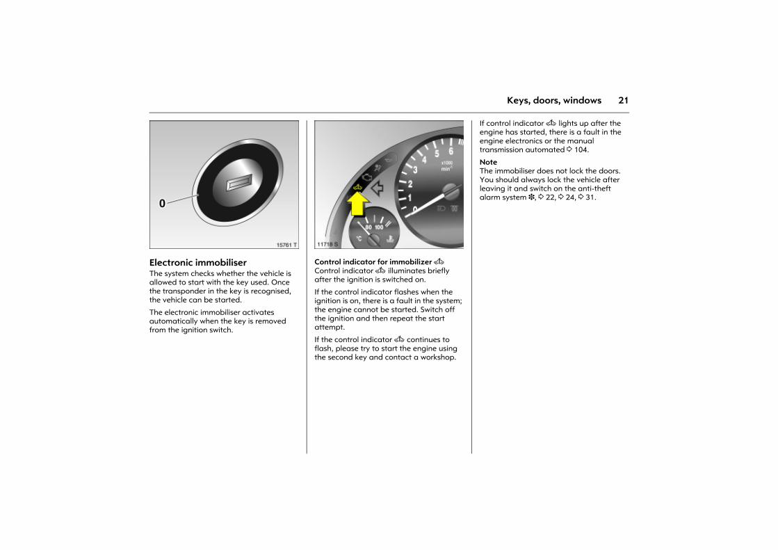
Picture no: 15761t.tifElectronic immobiliser The system checks whether the vehicle is allowed to start with the key used. Once the transponder in the key is recognised, the vehicle can be started.
The electronic immobiliser activates automatically when the key is removed from the ignition switch.
Picture no: 11718s.tifControl indicator for immobilizer A Control indicator A illuminates briefly after the ignition is switched on.
If the control indicator flashes when the ignition is on, there is a fault in the system; the engine cannot be started. Switch off the ignition and then repeat the start attempt.
If the control indicator A continues to flash, please try to start the engine using the second key and contact a workshop.
If control indicator A lights up after the engine has started, there is a fault in the engine electronics or the manual transmission automated 3 104.
Note The immobiliser does not lock the doors. You should always lock the vehicle after leaving it and switch on the anti-theft alarm system 3, 3 22, 3 24, 3 31.
22 Keys, doors, windows
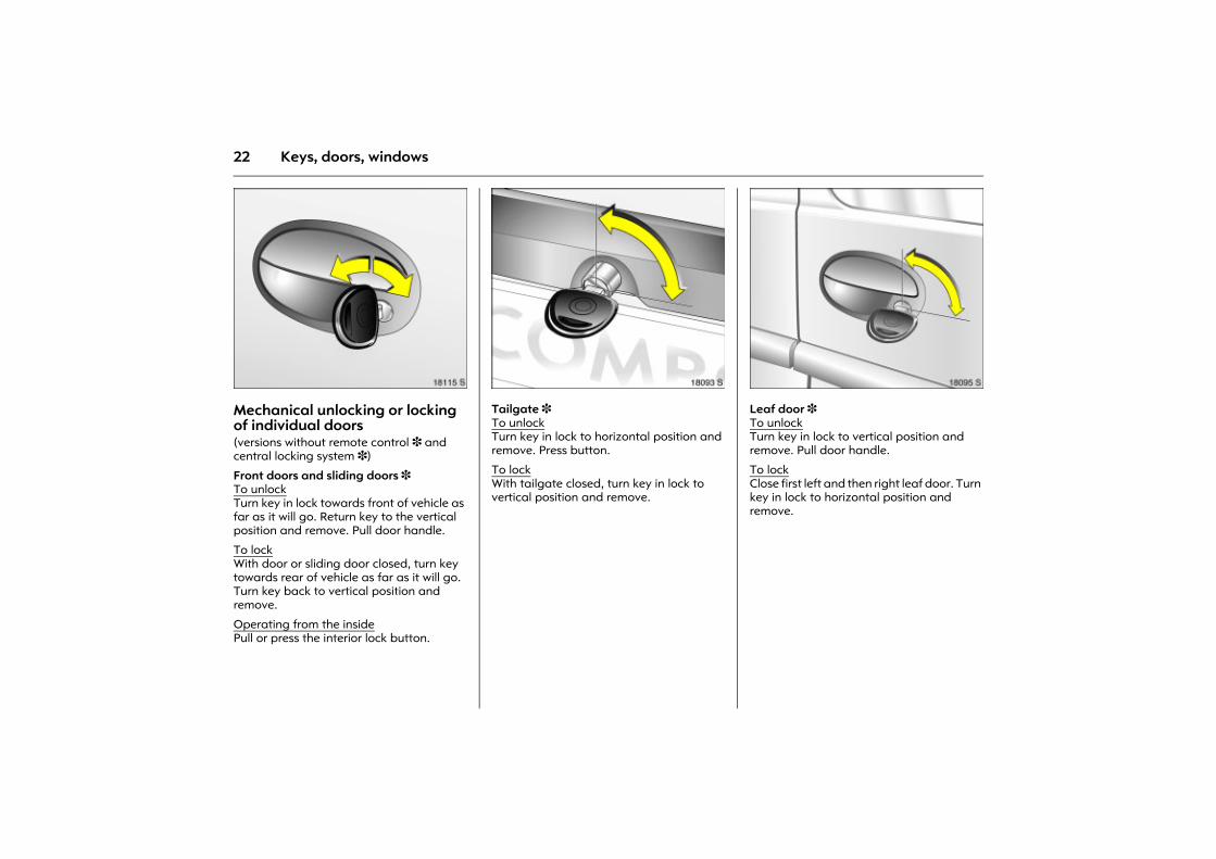
Picture no: 18115s.tifMechanical unlocking or locking of individual doors(versions without remote control 3 and central locking system 3)
Front doors and sliding doors 3 To unlockTurn key in lock towards front of vehicle as far as it will go. Return key to the vertical position and remove. Pull door handle.
To lockWith door or sliding door closed, turn key towards rear of vehicle as far as it will go. Turn key back to vertical position and remove.
Operating from the insidePull or press the interior lock button.
Picture no: 18093s.tifTailgate 3 To unlockTurn key in lock to horizontal position and remove. Press button.
To lockWith tailgate closed, turn key in lock to vertical position and remove.
Picture no: 18095s.tifLeaf door 3 To unlockTurn key in lock to vertical position and remove. Pull door handle.
To lockClose first left and then right leaf door. Turn key in lock to horizontal position and remove.
23Keys, doors, windows
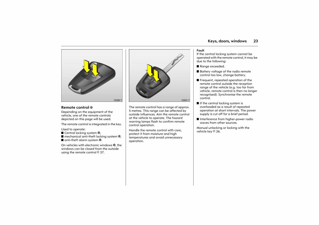
Picture no: 15330t.tifRemote control 3 Depending on the equipment of the vehicle, one of the remote controls depicted on this page will be used.
The remote control is integrated in the key.
Used to operate:z Central locking system 3, z mechanical anti-theft locking system 3, z anti-theft alarm system 3.
On vehicles with electronic windows 3, the windows can be closed from the outside using the remote control 3 37.
Picture no: 15331t.tifThe remote control has a range of approx. 5 metres. This range can be affected by outside influences. Aim the remote control at the vehicle to operate. The hazard warning lamps flash to confirm remote control operation.
Handle the remote control with care, protect it from moisture and high temperatures and avoid unnecessary operation.
Fault If the central locking system cannot be operated with the remote control, it may be due to the following:
z Range exceeded.
z Battery voltage of the radio remote control too low, change battery.
z Frequent, repeated operation of the remote control outside the reception range of the vehicle (e.g. too far from vehicle, remote control is then no longer recognised). Synchronise the remote control.
z If the central locking system is overloaded as a result of repeated operation at short intervals. The power supply is cut off for a brief period.
z Interference from higher-power radio waves from other sources.
Manual unlocking or locking with the vehicle key 3 26.
24 Keys, doors, windows
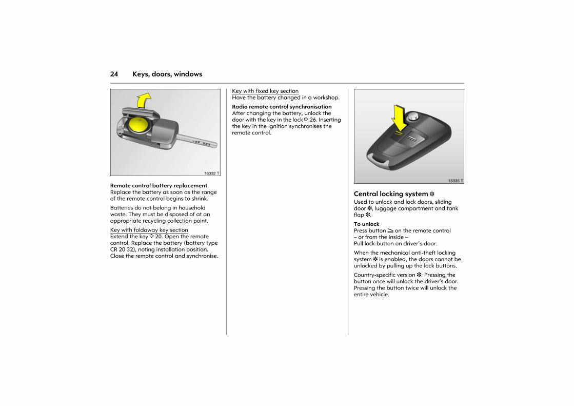
Picture no: 15332t.tifRemote control battery replacement Replace the battery as soon as the range of the remote control begins to shrink.
Batteries do not belong in household waste. They must be disposed of at an appropriate recycling collection point.
Key with foldaway key sectionExtend the key 3 20. Open the remote control. Replace the battery (battery type CR 20 32), noting installation position. Close the remote control and synchronise.
Key with fixed key sectionHave the battery changed in a workshop.
Radio remote control synchronisation After changing the battery, unlock the door with the key in the lock 3 26. Inserting the key in the ignition synchronises the remote control.
Picture no: 15335t.tifCentral locking system 3 Used to unlock and lock doors, sliding door 3, luggage compartment and tank flap 3.
To unlock Press button q on the remote control � or from the inside � Pull lock button on driver�s door.
When the mechanical anti-theft locking system 3 is enabled, the doors cannot be unlocked by pulling up the lock buttons.
Country-specific version 3: Pressing the button once will unlock the driver�s door. Pressing the button twice will unlock the entire vehicle.
25Keys, doors, windows
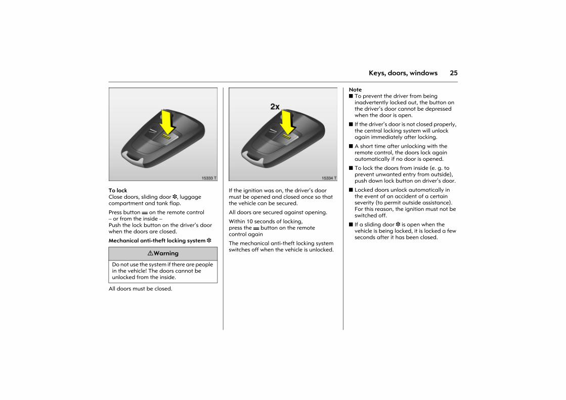
Picture no: 15333t.tifTo lock Close doors, sliding door 3, luggage compartment and tank flap.
Press button p on the remote control � or from the inside � Push the lock button on the driver�s door when the doors are closed.
Mechanical anti-theft locking system 3
All doors must be closed.
Picture no: 15334t.tifIf the ignition was on, the driver�s door must be opened and closed once so that the vehicle can be secured.
All doors are secured against opening.
Within 10 seconds of locking, press the p button on the remote control again
The mechanical anti-theft locking system switches off when the vehicle is unlocked.
Note z To prevent the driver from being
inadvertently locked out, the button on the driver�s door cannot be depressed when the door is open.
z If the driver�s door is not closed properly, the central locking system will unlock again immediately after locking.
z A short time after unlocking with the remote control, the doors lock again automatically if no door is opened.
z To lock the doors from inside (e. g. to prevent unwanted entry from outside), push down lock button on driver�s door.
z Locked doors unlock automatically in the event of an accident of a certain severity (to permit outside assistance). For this reason, the ignition must not be switched off.
z If a sliding door 3 is open when the vehicle is being locked, it is locked a few seconds after it has been closed.
9 Warning
Do not use the system if there are people in the vehicle! The doors cannot be unlocked from the inside.
26 Keys, doors, windows
Fault If the central locking system cannot be operated, the problem may be as follows:
z If the central locking system is overloaded as a result of repeated operation at short intervals. The power supply is cut off for a brief period.
z Defective fuse in the fuse box 3 147.
Please contact a workshop to have the cause of the fault remedied.
Operate the driver�s door with the key.
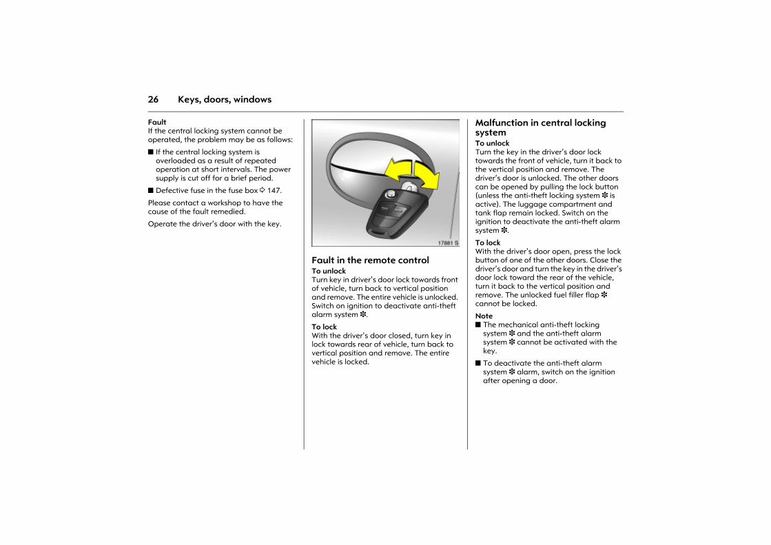
Picture no: 17881s.tifFault in the remote control To unlockTurn key in driver�s door lock towards front of vehicle, turn back to vertical position and remove. The entire vehicle is unlocked. Switch on ignition to deactivate anti-theft alarm system 3.
To lock With the driver�s door closed, turn key in lock towards rear of vehicle, turn back to vertical position and remove. The entire vehicle is locked.
Malfunction in central locking system To unlock Turn the key in the driver�s door lock towards the front of vehicle, turn it back to the vertical position and remove. The driver�s door is unlocked. The other doors can be opened by pulling the lock button (unless the anti-theft locking system 3 is active). The luggage compartment and tank flap remain locked. Switch on the ignition to deactivate the anti-theft alarm system 3.
To lock With the driver�s door open, press the lock button of one of the other doors. Close the driver�s door and turn the key in the driver�s door lock toward the rear of the vehicle, turn it back to the vertical position and remove. The unlocked fuel filler flap 3 cannot be locked.
Notez The mechanical anti-theft locking
system 3 and the anti-theft alarm system 3 cannot be activated with the key.
z To deactivate the anti-theft alarm system 3 alarm, switch on the ignition after opening a door.
27Keys, doors, windows
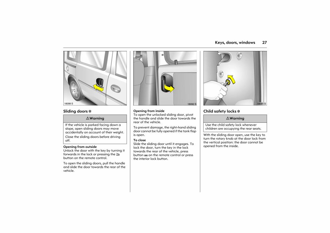
Picture no: 18098s.tifSliding doors 3
Opening from outside Unlock the door with the key by turning it forwards in the lock or pressing the q button on the remote control.
To open the sliding doors, pull the handle and slide the door towards the rear of the vehicle.
Picture no: 18092s.tifOpening from inside To open the unlocked sliding door, pivot the handle and slide the door towards the rear of the vehicle.
To prevent damage, the right-hand sliding door cannot be fully opened if the tank flap is open.
To close Slide the sliding door until it engages. To lock the door, turn the key in the lock towards the rear of the vehicle, press button p on the remote control or press the interior lock button.
Picture no: 18091s.tifChild safety locks 3
With the sliding door open, use the key to turn the rotary knob at the door lock from the vertical position: the door cannot be opened from the inside.
9 Warning
If the vehicle is parked facing down a slope, open sliding doors may move accidentally on account of their weight. Close the sliding doors before driving off.
9 Warning
Use the child safety lock whenever children are occupying the rear seats.
28 Keys, doors, windows
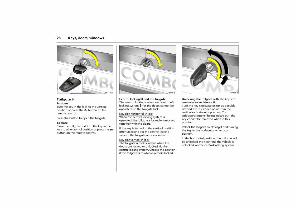
Picture no: 18116s.tifTailgate 3 To open Turn the key in the lock to the vertical position or press the q button on the remote control.
Press the button to open the tailgate.
To close Close the tailgate and turn the key in the lock to a horizontal position or press the p button on the remote control.
Picture no: 18118s.tifCentral locking 3 and the tailgate The central locking system and anti-theft locking system 3 for the doors cannot be operated via the tailgate lock.
Key slot horizontal in lock When the central locking system is operated, the tailgate is locked or unlocked together with the doors.
If the key is turned to the vertical position after unlocking via the central locking system, the tailgate remains locked.
Key slot vertical in lockThe tailgate remains locked when the doors are locked or unlocked via the central locking system. Choose this position if the tailgate is to always remain locked.
Picture no: 18094s.tifUnlocking the tailgate with the key with centrally locked doors 3Turn the key clockwise as far as possible beyond the resistance point from the vertical or horizontal position. To safeguard against being locked out, the key cannot be removed when in this position.
Relock the tailgate by closing it and turning the key to the horizontal or vertical position.
In the horizontal position, the tailgate will be unlocked the next time the vehicle is unlocked via the central locking system.
29Keys, doors, windows
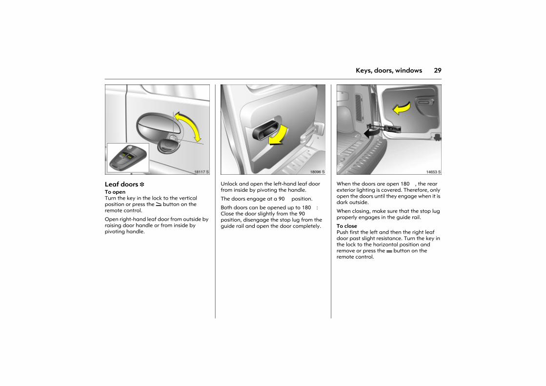
Picture no: 18117s.tifLeaf doors 3 To open Turn the key in the lock to the vertical position or press the q button on the remote control.
Open right-hand leaf door from outside by raising door handle or from inside by pivoting handle.
Picture no: 18096s.tifUnlock and open the left-hand leaf door from inside by pivoting the handle.
The doors engage at a 90� position.
Both doors can be opened up to 180�: Close the door slightly from the 90� position, disengage the stop lug from the guide rail and open the door completely.
Picture no: 14653s.tifWhen the doors are open 180�, the rear exterior lighting is covered. Therefore, only open the doors until they engage when it is dark outside.
When closing, make sure that the stop lug properly engages in the guide rail.
To close Push first the left and then the right leaf door past slight resistance. Turn the key in the lock to the horizontal position and remove or press the p button on the remote control.
30 Keys, doors, windows
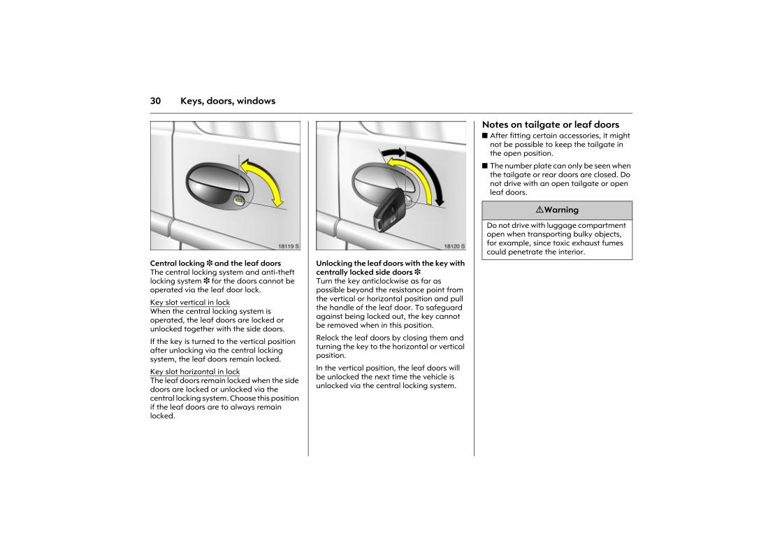
Picture no: 18119s.tifCentral locking 3 and the leaf doors The central locking system and anti-theft locking system 3 for the doors cannot be operated via the leaf door lock.
Key slot vertical in lock When the central locking system is operated, the leaf doors are locked or unlocked together with the side doors.
If the key is turned to the vertical position after unlocking via the central locking system, the leaf doors remain locked.
Key slot horizontal in lockThe leaf doors remain locked when the side doors are locked or unlocked via the central locking system. Choose this position if the leaf doors are to always remain locked.
Picture no: 18120s.tifUnlocking the leaf doors with the key with centrally locked side doors 3Turn the key anticlockwise as far as possible beyond the resistance point from the vertical or horizontal position and pull the handle of the leaf door. To safeguard against being locked out, the key cannot be removed when in this position.
Relock the leaf doors by closing them and turning the key to the horizontal or vertical position.
In the vertical position, the leaf doors will be unlocked the next time the vehicle is unlocked via the central locking system.
Notes on tailgate or leaf doors z After fitting certain accessories, it might
not be possible to keep the tailgate in the open position.
z The number plate can only be seen when the tailgate or rear doors are closed. Do not drive with an open tailgate or open leaf doors.
9 Warning
Do not drive with luggage compartment open when transporting bulky objects, for example, since toxic exhaust fumes could penetrate the interior.
31Keys, doors, windows
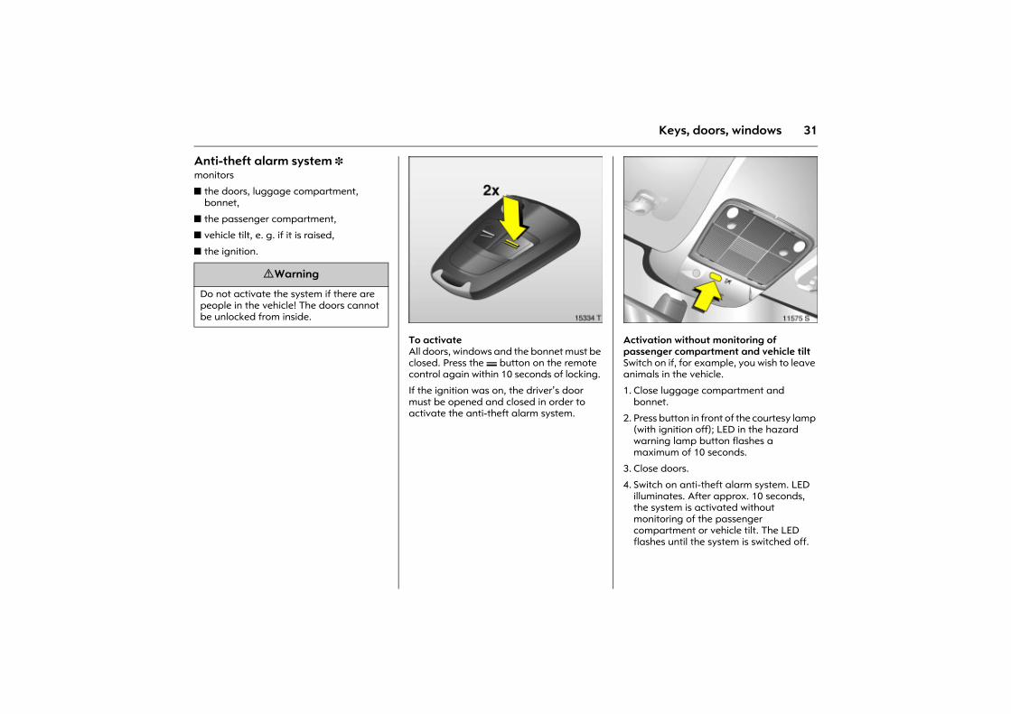
Anti-theft alarm system 3 monitors
z the doors, luggage compartment, bonnet,
z the passenger compartment,
z vehicle tilt, e. g. if it is raised,
z the ignition.
Picture no: 15334t.tifTo activate All doors, windows and the bonnet must be closed. Press the p button on the remote control again within 10 seconds of locking.
If the ignition was on, the driver�s door must be opened and closed in order to activate the anti-theft alarm system.
Picture no: 11575s.tifActivation without monitoring of passenger compartment and vehicle tilt Switch on if, for example, you wish to leave animals in the vehicle.
1. Close luggage compartment and bonnet.
2. Press button in front of the courtesy lamp (with ignition off); LED in the hazard warning lamp button flashes a maximum of 10 seconds.
3. Close doors.
4. Switch on anti-theft alarm system. LED illuminates. After approx. 10 seconds, the system is activated without monitoring of the passenger compartment or vehicle tilt. The LED flashes until the system is switched off.
9 Warning
Do not activate the system if there are people in the vehicle! The doors cannot be unlocked from inside.
32 Keys, doors, windows
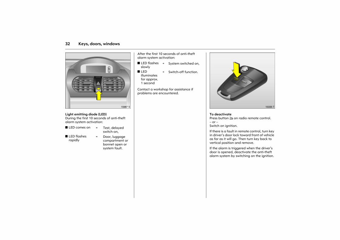
Picture no: 15987s.tifLight emitting diode (LED) During the first 10 seconds of anti-theft alarm system activation:
After the first 10 seconds of anti-theft alarm system activation:
Contact a workshop for assistance if problems are encountered.
Picture no: 15335t.tifTo deactivate Press button q on radio remote control. � or � Switch on ignition.
If there is a fault in remote control, turn key in driver�s door lock toward front of vehicle as far as it will go. Then turn key back to vertical position and remove.
If the alarm is triggered when the driver�s door is opened, deactivate the anti-theft alarm system by switching on the ignition.
z LED comes on = Test, delayed switch-on,
z LED flashes rapidly
= Door, luggage compartment or bonnet open or system fault.
z LED flashes slowly
= System switched on,
z LED illuminates for approx. 1 second
= Switch-off function.
33Keys, doors, windows
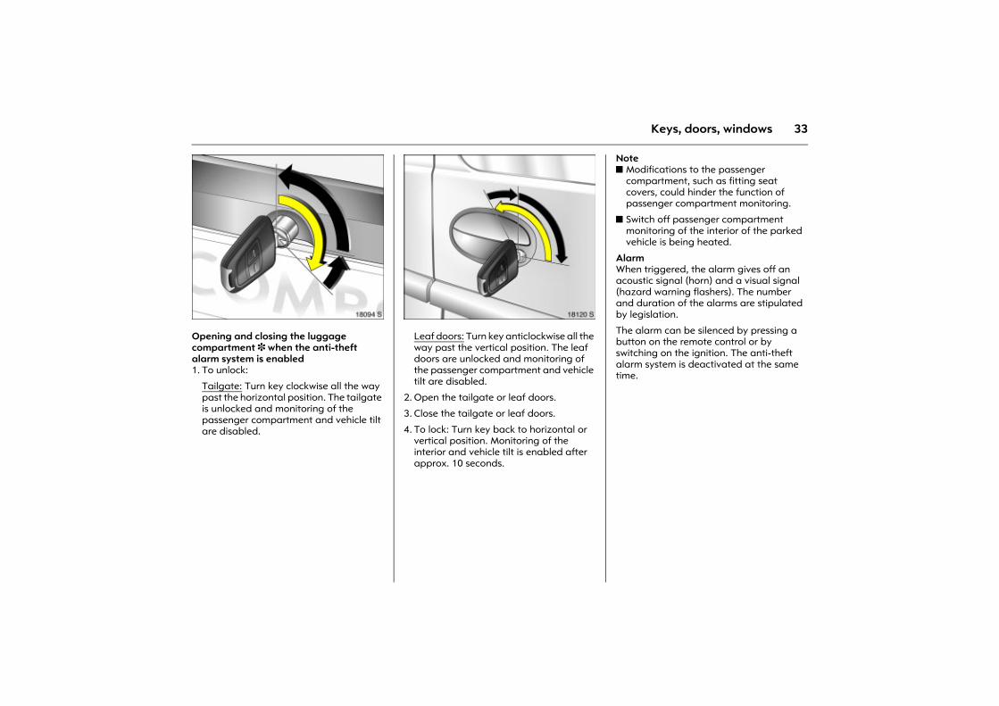
Picture no: 18094s.tifOpening and closing the luggage compartment 3 when the anti-theft alarm system is enabled 1. To unlock:
Tailgate: Turn key clockwise all the way past the horizontal position. The tailgate is unlocked and monitoring of the passenger compartment and vehicle tilt are disabled.
Picture no: 18120s.tifLeaf doors: Turn key anticlockwise all the way past the vertical position. The leaf doors are unlocked and monitoring of the passenger compartment and vehicle tilt are disabled.
2. Open the tailgate or leaf doors.
3. Close the tailgate or leaf doors.
4. To lock: Turn key back to horizontal or vertical position. Monitoring of the interior and vehicle tilt is enabled after approx. 10 seconds.
Note z Modifications to the passenger
compartment, such as fitting seat covers, could hinder the function of passenger compartment monitoring.
z Switch off passenger compartment monitoring of the interior of the parked vehicle is being heated.
Alarm When triggered, the alarm gives off an acoustic signal (horn) and a visual signal (hazard warning flashers). The number and duration of the alarms are stipulated by legislation.
The alarm can be silenced by pressing a button on the remote control or by switching on the ignition. The anti-theft alarm system is deactivated at the same time.
34 Keys, doors, windows
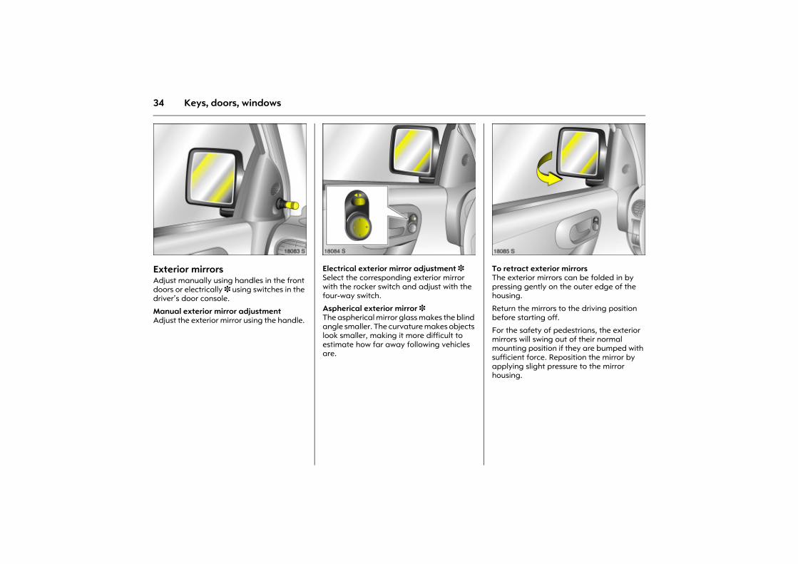
Picture no: 18083s.tifExterior mirrors Adjust manually using handles in the front doors or electrically 3 using switches in the driver�s door console.
Manual exterior mirror adjustment Adjust the exterior mirror using the handle.
Picture no: 18084s.tifElectrical exterior mirror adjustment 3 Select the corresponding exterior mirror with the rocker switch and adjust with the four-way switch.
Aspherical exterior mirror 3 The aspherical mirror glass makes the blind angle smaller. The curvature makes objects look smaller, making it more difficult to estimate how far away following vehicles are.
Picture no: 18085s.tifTo retract exterior mirrors The exterior mirrors can be folded in by pressing gently on the outer edge of the housing.
Return the mirrors to the driving position before starting off.
For the safety of pedestrians, the exterior mirrors will swing out of their normal mounting position if they are bumped with sufficient force. Reposition the mirror by applying slight pressure to the mirror housing.
35Keys, doors, windows
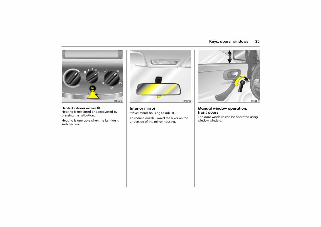
Picture no: 11549s.tifHeated exterior mirrors 3 Heating is activated or deactivated by pressing the Ü button.
Heating is operable when the ignition is switched on.
Picture no: 18082s.tifInterior mirror Swivel mirror housing to adjust.
To reduce dazzle, swivel the lever on the underside of the mirror housing.
Picture no: 18104s.tifManual window operation, front doors The door windows can be operated using window winders.
36 Keys, doors, windows
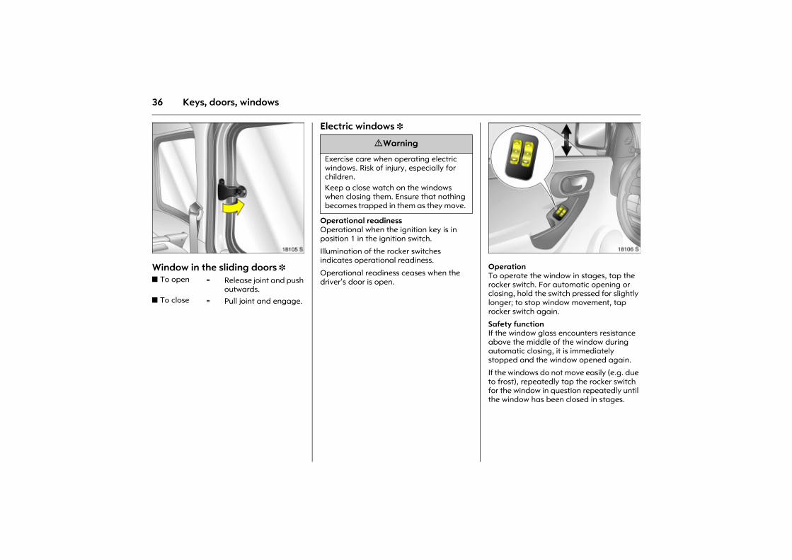
Picture no: 18105s.tifWindow in the sliding doors 3
Electric windows 3
Operational readinessOperational when the ignition key is in position 1 in the ignition switch.
Illumination of the rocker switches indicates operational readiness.
Operational readiness ceases when the driver�s door is open.
Picture no: 18106s.tifOperation To operate the window in stages, tap the rocker switch. For automatic opening or closing, hold the switch pressed for slightly longer; to stop window movement, tap rocker switch again.
Safety function If the window glass encounters resistance above the middle of the window during automatic closing, it is immediately stopped and the window opened again.
If the windows do not move easily (e.g. due to frost), repeatedly tap the rocker switch for the window in question repeatedly until the window has been closed in stages.
z To open = Release joint and push outwards.
z To close = Pull joint and engage.
9 Warning
Exercise care when operating electric windows. Risk of injury, especially for children. Keep a close watch on the windows when closing them. Ensure that nothing becomes trapped in them as they move.
37Keys, doors, windows
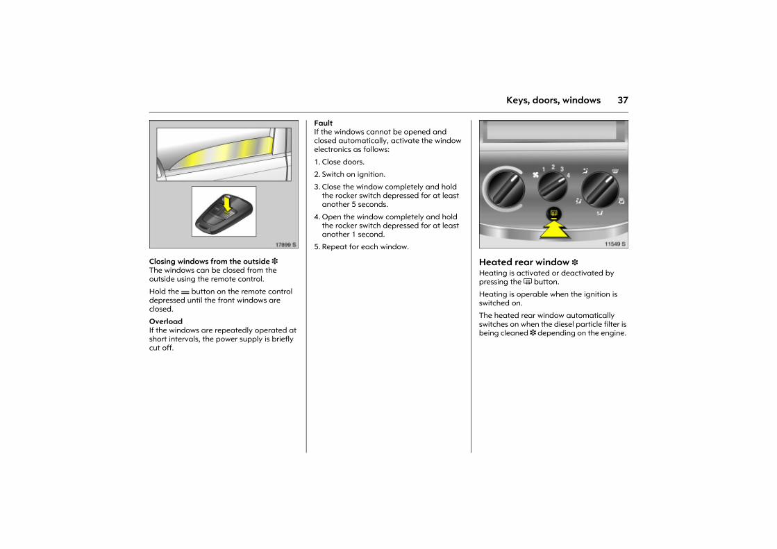
Picture no: 17899s.tifClosing windows from the outside 3 The windows can be closed from the outside using the remote control.
Hold the p button on the remote control depressed until the front windows are closed.
Overload If the windows are repeatedly operated at short intervals, the power supply is briefly cut off.
Fault If the windows cannot be opened and closed automatically, activate the window electronics as follows:
1. Close doors.
2. Switch on ignition.
3. Close the window completely and hold the rocker switch depressed for at least another 5 seconds.
4. Open the window completely and hold the rocker switch depressed for at least another 1 second.
5. Repeat for each window. Picture no: 11549s.tif
Heated rear window 3 Heating is activated or deactivated by pressing the Ü button.
Heating is operable when the ignition is switched on.
The heated rear window automatically switches on when the diesel particle filter is being cleaned 3 depending on the engine.
38 Seats, Interior
Seats, Interior
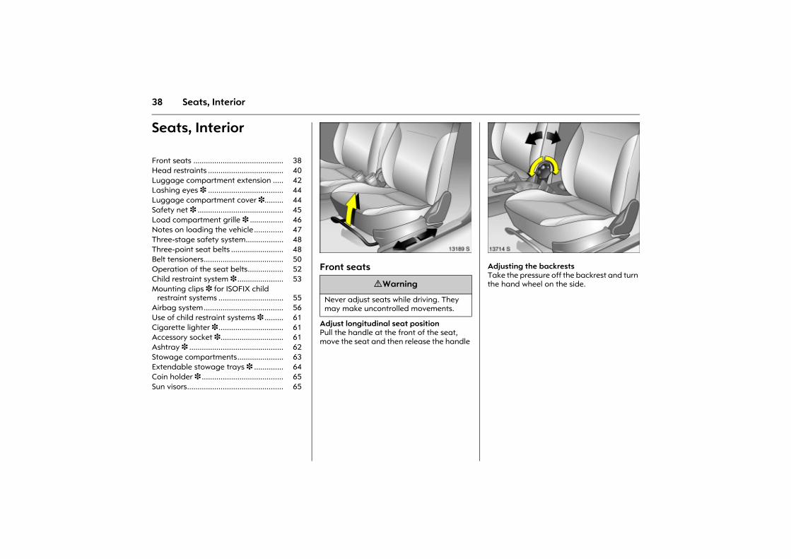
Picture no: 13189s.tifFront seats
Adjust longitudinal seat positionPull the handle at the front of the seat, move the seat and then release the handle
Picture no: 13714s.tifAdjusting the backrestsTake the pressure off the backrest and turn the hand wheel on the side.
Front seats ........................................... 38 Head restraints .................................... 40 Luggage compartment extension ..... 42 Lashing eyes 3 .................................... 44 Luggage compartment cover 3......... 44 Safety net 3 ......................................... 45 Load compartment grille 3 ................ 46 Notes on loading the vehicle.............. 47 Three-stage safety system.................. 48 Three-point seat belts ......................... 48 Belt tensioners...................................... 50 Operation of the seat belts................. 52 Child restraint system 3 ...................... 53 Mounting clips 3 for ISOFIX child
restraint systems ............................... 55 Airbag system...................................... 56 Use of child restraint systems 3 ......... 61 Cigarette lighter 3 ............................... 61 Accessory socket 3.............................. 61 Ashtray 3 ............................................. 62 Stowage compartments...................... 63 Extendable stowage trays 3 .............. 64 Coin holder 3 ....................................... 65 Sun visors.............................................. 65
9 Warning
Never adjust seats while driving. They may make uncontrolled movements.
39Seats, Interior
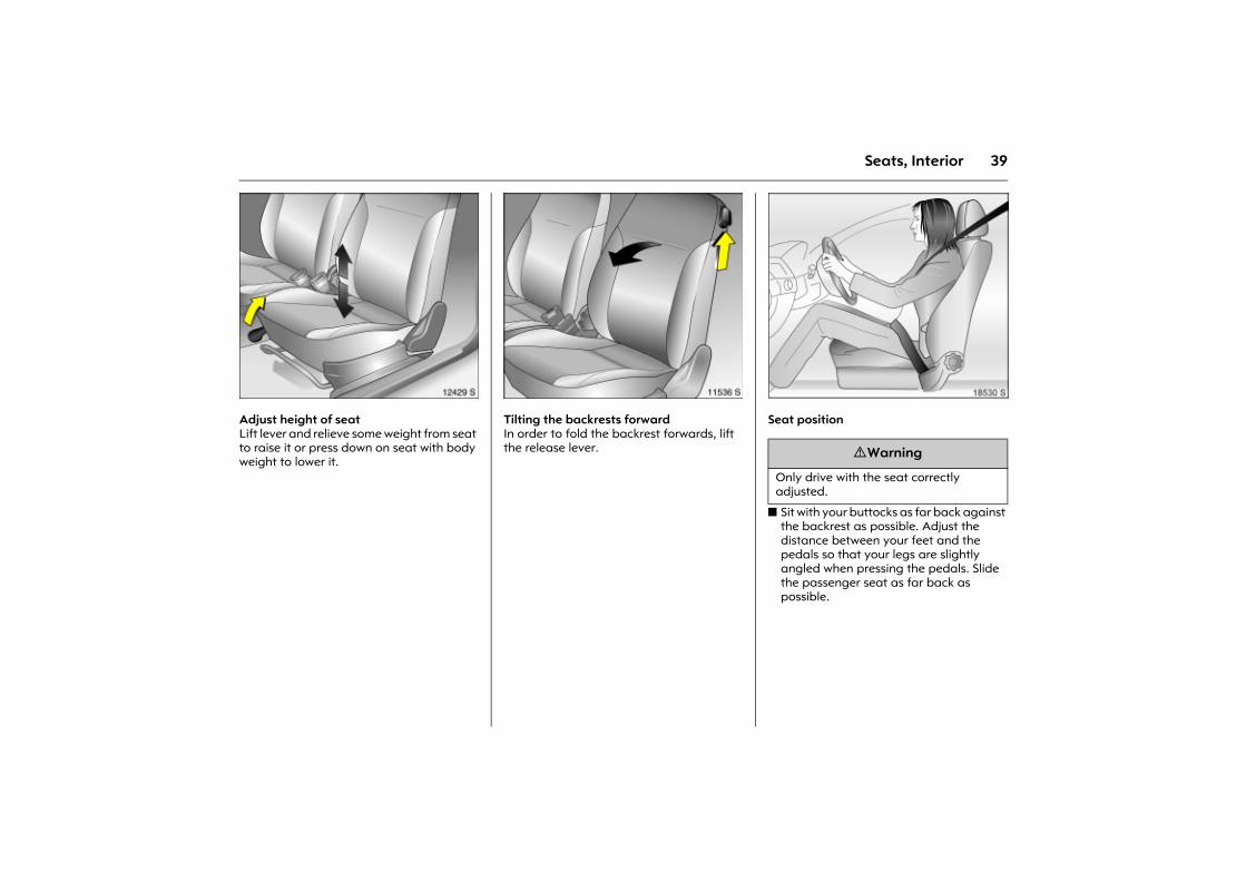
Picture no: 12429s.tifAdjust height of seatLift lever and relieve some weight from seat to raise it or press down on seat with body weight to lower it.
Picture no: 11536s.tifTilting the backrests forward In order to fold the backrest forwards, lift the release lever.
Picture no: 18530s.tifSeat position
z Sit with your buttocks as far back against the backrest as possible. Adjust the distance between your feet and the pedals so that your legs are slightly angled when pressing the pedals. Slide the passenger seat as far back as possible.
9 Warning
Only drive with the seat correctly adjusted.
40 Seats, Interior
z Sit with your shoulders as far back against the backrest as possible. Set the backrest rake so that you can easily reach the steering wheel with your arms slightly bent. Maintain contact between your shoulders and the backrest when turning the steering wheel. Do not angle the backrest too far back. We recommend a maximum rake of approx. 25�.
z Adjust the steering wheel 3 6.
z Set seat height 3 high enough to have a clear field of vision on all sides and of all display instruments. There should be at least six inches of clearance between your head and the headlining. Your thighs should rest lightly on the seat without pressing into it.
z Adjust the head restraint.
z Adjust the height of the seat belt 3 52.
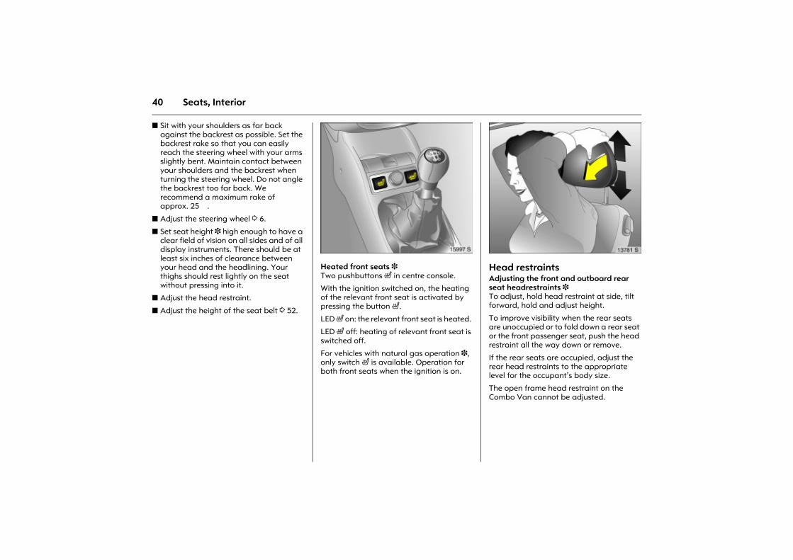
Picture no: 15997s.tifHeated front seats 3 Two pushbuttons ß in centre console.
With the ignition switched on, the heating of the relevant front seat is activated by pressing the button ß.
LED ß on: the relevant front seat is heated.
LED ß off: heating of relevant front seat is switched off.
For vehicles with natural gas operation 3, only switch ß is available. Operation for both front seats when the ignition is on.
Picture no: 13781s.tifHead restraints Adjusting the front and outboard rear seat headrestraints 3 To adjust, hold head restraint at side, tilt forward, hold and adjust height.
To improve visibility when the rear seats are unoccupied or to fold down a rear seat or the front passenger seat, push the head restraint all the way down or remove.
If the rear seats are occupied, adjust the rear head restraints to the appropriate level for the occupant�s body size.
The open frame head restraint on the Combo Van cannot be adjusted.
41Seats, Interior
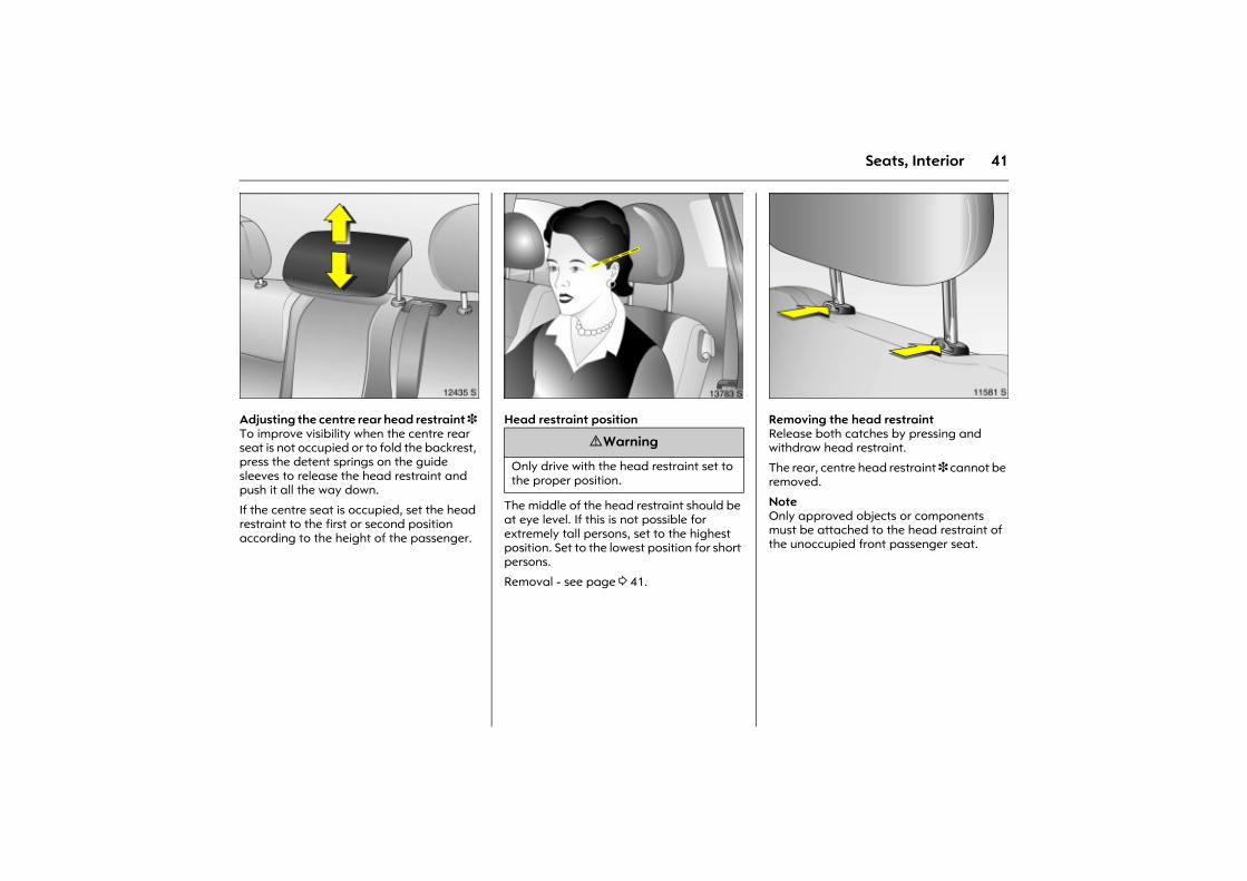
Picture no: 12435s.tifAdjusting the centre rear head restraint 3 To improve visibility when the centre rear seat is not occupied or to fold the backrest, press the detent springs on the guide sleeves to release the head restraint and push it all the way down.
If the centre seat is occupied, set the head restraint to the first or second position according to the height of the passenger.
Picture no: 13783s.tifHead restraint position
The middle of the head restraint should be at eye level. If this is not possible for extremely tall persons, set to the highest position. Set to the lowest position for short persons. Removal - see page 3 41.
Picture no: 11581s.tifRemoving the head restraint Release both catches by pressing and withdraw head restraint.
The rear, centre head restraint 3 cannot be removed.
Note Only approved objects or components must be attached to the head restraint of the unoccupied front passenger seat.
9 Warning
Only drive with the head restraint set to the proper position.
42 Seats, Interior
Luggage compartment extension Remove the luggage compartment cover 3 if necessary 3 44.
Pull out the push-in collars 3 for the ISOFIX child-restraint system mounting.
Closely follow the installation instructions accompanying the ISOFIX child restraint system.
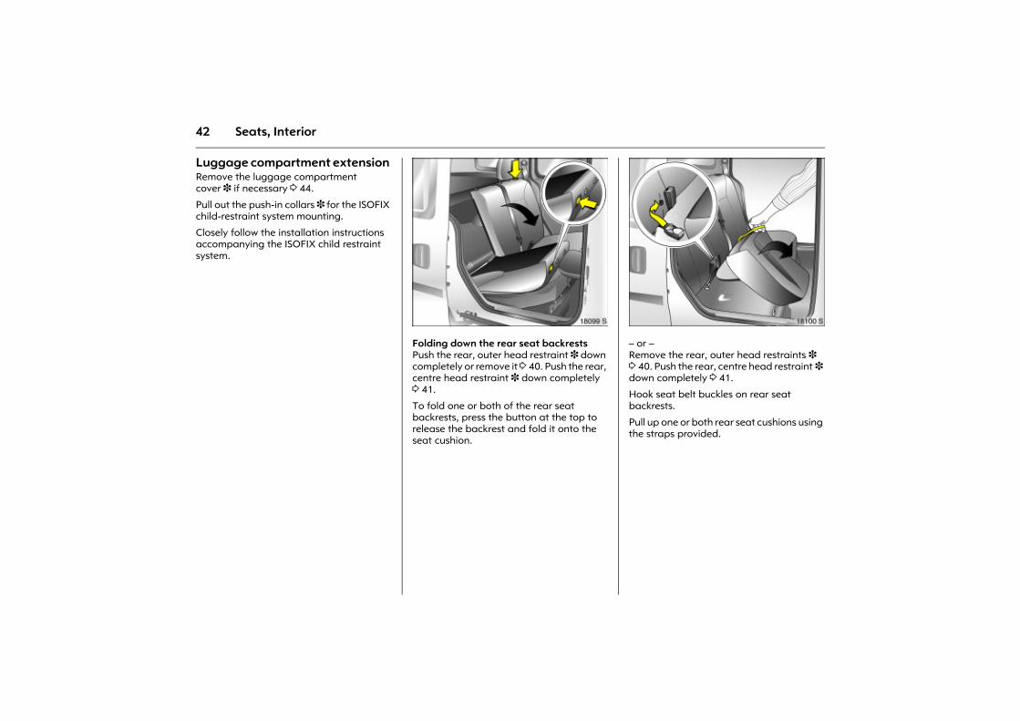
Picture no: 18099s.tifFolding down the rear seat backrestsPush the rear, outer head restraint 3 down completely or remove it 3 40. Push the rear, centre head restraint 3 down completely 3 41.
To fold one or both of the rear seat backrests, press the button at the top to release the backrest and fold it onto the seat cushion.
Picture no: 18100s.tif� or � Remove the rear, outer head restraints 3 3 40. Push the rear, centre head restraint 3 down completely 3 41.
Hook seat belt buckles on rear seat backrests.
Pull up one or both rear seat cushions using the straps provided.
43Seats, Interior
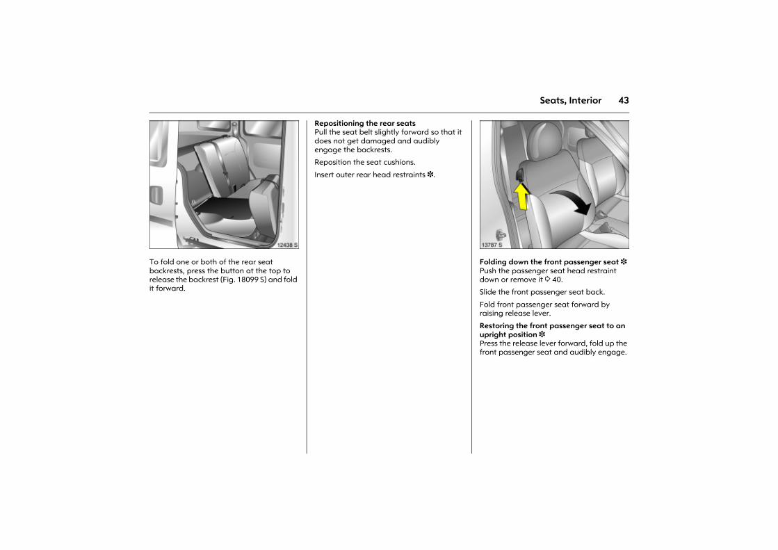
Picture no: 12438s.tifTo fold one or both of the rear seat backrests, press the button at the top to release the backrest (Fig. 18099 S) and fold it forward.
Repositioning the rear seatsPull the seat belt slightly forward so that it does not get damaged and audibly engage the backrests.
Reposition the seat cushions.
Insert outer rear head restraints 3.
Picture no: 13787s.tifFolding down the front passenger seat 3 Push the passenger seat head restraint down or remove it 3 40.
Slide the front passenger seat back.
Fold front passenger seat forward by raising release lever.
Restoring the front passenger seat to an upright position 3 Press the release lever forward, fold up the front passenger seat and audibly engage.
44 Seats, Interior
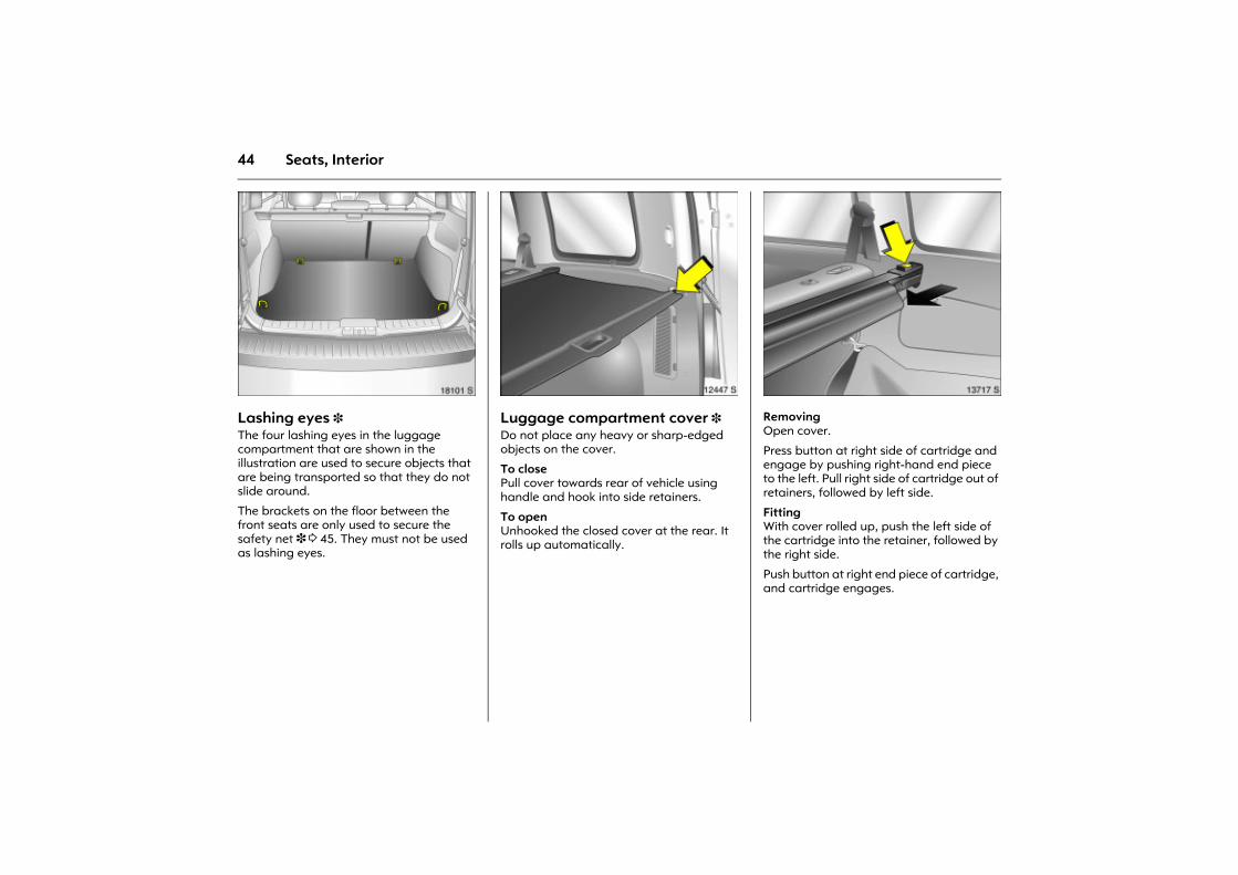
Picture no: 18101s.tifLashing eyes 3 The four lashing eyes in the luggage compartment that are shown in the illustration are used to secure objects that are being transported so that they do not slide around.
The brackets on the floor between the front seats are only used to secure the safety net 3 3 45. They must not be used as lashing eyes.
Picture no: 12447s.tifLuggage compartment cover 3 Do not place any heavy or sharp-edged objects on the cover.
To close Pull cover towards rear of vehicle using handle and hook into side retainers.
To open Unhooked the closed cover at the rear. It rolls up automatically.
Picture no: 13717s.tifRemoving Open cover.
Press button at right side of cartridge and engage by pushing right-hand end piece to the left. Pull right side of cartridge out of retainers, followed by left side.
Fitting With cover rolled up, push the left side of the cartridge into the retainer, followed by the right side.
Push button at right end piece of cartridge, and cartridge engages.
45Seats, Interior
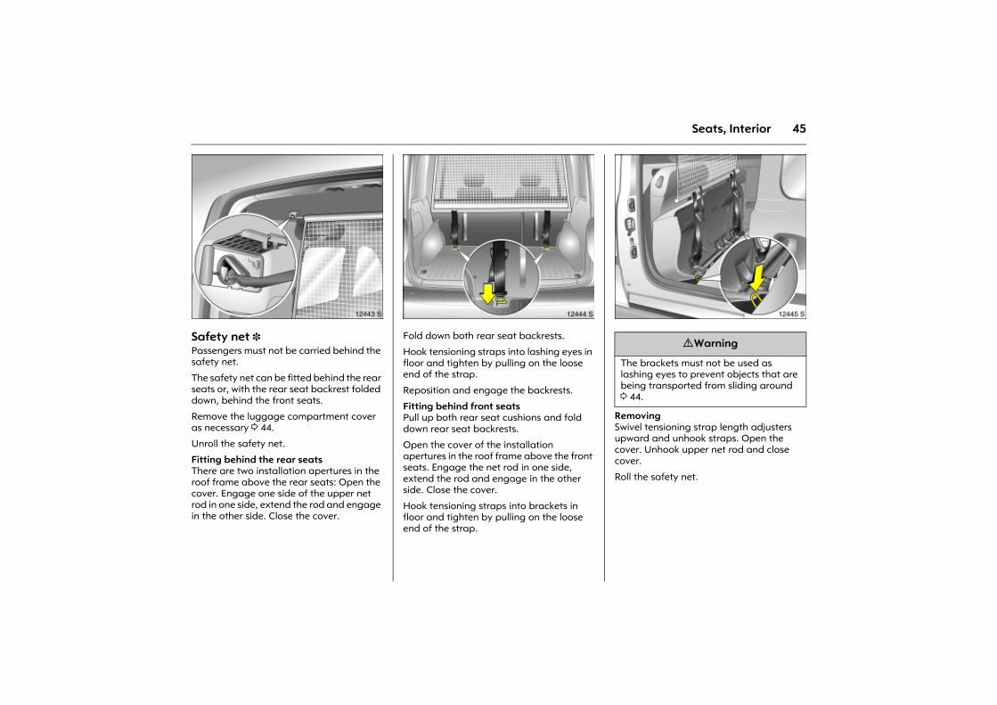
Picture no: 12443s.tifSafety net 3 Passengers must not be carried behind the safety net.
The safety net can be fitted behind the rear seats or, with the rear seat backrest folded down, behind the front seats.
Remove the luggage compartment cover as necessary 3 44.
Unroll the safety net.
Fitting behind the rear seats There are two installation apertures in the roof frame above the rear seats: Open the cover. Engage one side of the upper net rod in one side, extend the rod and engage in the other side. Close the cover.
Picture no: 12444s.tifFold down both rear seat backrests.
Hook tensioning straps into lashing eyes in floor and tighten by pulling on the loose end of the strap.
Reposition and engage the backrests.
Fitting behind front seats Pull up both rear seat cushions and fold down rear seat backrests.
Open the cover of the installation apertures in the roof frame above the front seats. Engage the net rod in one side, extend the rod and engage in the other side. Close the cover.
Hook tensioning straps into brackets in floor and tighten by pulling on the loose end of the strap.
Picture no: 12445s.tif
Removing Swivel tensioning strap length adjusters upward and unhook straps. Open the cover. Unhook upper net rod and close cover.
Roll the safety net.
9 Warning
The brackets must not be used as lashing eyes to prevent objects that are being transported from sliding around 3 44.
46 Seats, Interior
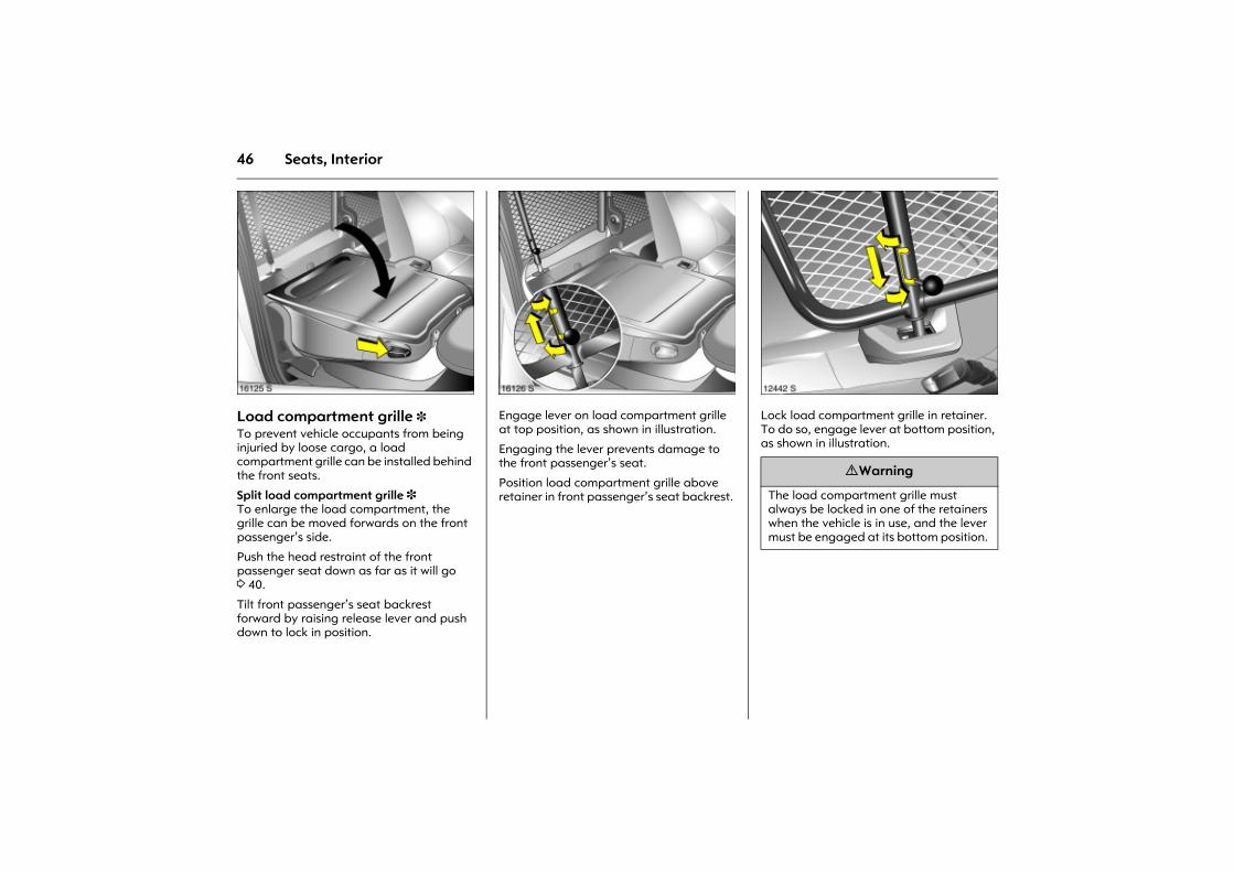
Picture no: 16125s.tifLoad compartment grille 3 To prevent vehicle occupants from being injuried by loose cargo, a load compartment grille can be installed behind the front seats.
Split load compartment grille 3 To enlarge the load compartment, the grille can be moved forwards on the front passenger�s side.
Push the head restraint of the front passenger seat down as far as it will go 3 40.
Tilt front passenger�s seat backrest forward by raising release lever and push down to lock in position.
Picture no: 16126s.tifEngage lever on load compartment grille at top position, as shown in illustration.
Engaging the lever prevents damage to the front passenger�s seat.
Position load compartment grille above retainer in front passenger�s seat backrest.
Picture no: 12442s.tifLock load compartment grille in retainer. To do so, engage lever at bottom position, as shown in illustration.
9 Warning
The load compartment grille must always be locked in one of the retainers when the vehicle is in use, and the lever must be engaged at its bottom position.
47Seats, Interior
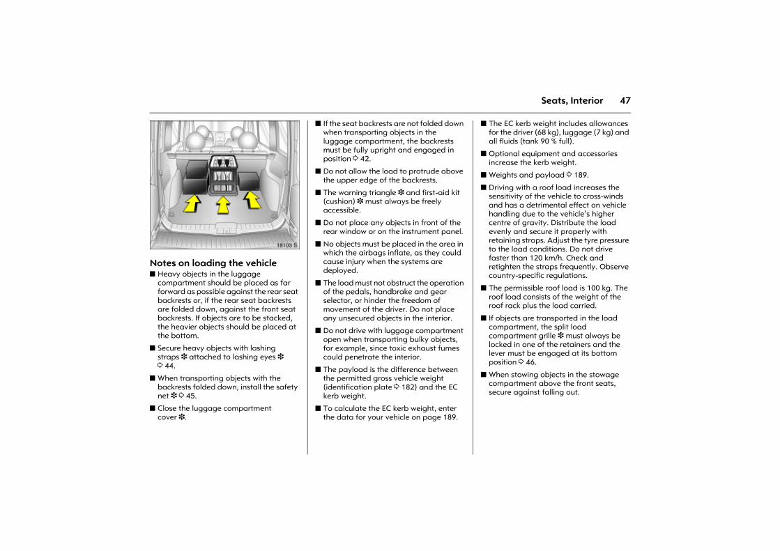
Picture no: 18103s.tifNotes on loading the vehicle z Heavy objects in the luggage
compartment should be placed as far forward as possible against the rear seat backrests or, if the rear seat backrests are folded down, against the front seat backrests. If objects are to be stacked, the heavier objects should be placed at the bottom.
z Secure heavy objects with lashing straps 3 attached to lashing eyes 3 3 44.
z When transporting objects with the backrests folded down, install the safety net 3 3 45.
z Close the luggage compartment cover 3.
z If the seat backrests are not folded down when transporting objects in the luggage compartment, the backrests must be fully upright and engaged in position 3 42.
z Do not allow the load to protrude above the upper edge of the backrests.
z The warning triangle 3 and first-aid kit (cushion) 3 must always be freely accessible.
z Do not place any objects in front of the rear window or on the instrument panel.
z No objects must be placed in the area in which the airbags inflate, as they could cause injury when the systems are deployed.
z The load must not obstruct the operation of the pedals, handbrake and gear selector, or hinder the freedom of movement of the driver. Do not place any unsecured objects in the interior.
z Do not drive with luggage compartment open when transporting bulky objects, for example, since toxic exhaust fumes could penetrate the interior.
z The payload is the difference between the permitted gross vehicle weight (identification plate 3 182) and the EC kerb weight.
z To calculate the EC kerb weight, enter the data for your vehicle on page 189.
z The EC kerb weight includes allowances for the driver (68 kg), luggage (7 kg) and all fluids (tank 90 % full).
z Optional equipment and accessories increase the kerb weight.
z Weights and payload 3 189.
z Driving with a roof load increases the sensitivity of the vehicle to cross-winds and has a detrimental effect on vehicle handling due to the vehicle�s higher centre of gravity. Distribute the load evenly and secure it properly with retaining straps. Adjust the tyre pressure to the load conditions. Do not drive faster than 120 km/h. Check and retighten the straps frequently. Observe country-specific regulations.
z The permissible roof load is 100 kg. The roof load consists of the weight of the roof rack plus the load carried.
z If objects are transported in the load compartment, the split load compartment grille 3 must always be locked in one of the retainers and the lever must be engaged at its bottom position 3 46.
z When stowing objects in the stowage compartment above the front seats, secure against falling out.
48 Seats, Interior
Three-stage safety system Comprising:
z three-point seat belts,
z belt tensioners at the front seats,
z airbag systems for driver and front passenger 3.
The three stages are activated in sequence depending on the severity of the accident:
z The automatic seat belt locking devices prevent the belt strap from being pulled out and thus ensure that the vehicle occupants are retained in their seats.
z The seat belts of the front seats are pulled downwards at the belt buckles. This tightens the seat belt, the occupants are slowed down at an early stage of vehicle deceleration and stress on the body is reduced.
z The airbag systems are also triggered in the event of severe accidents and form a safety cushion for the occupants.
Carefully follow the instructions accompanying the child restraint system.
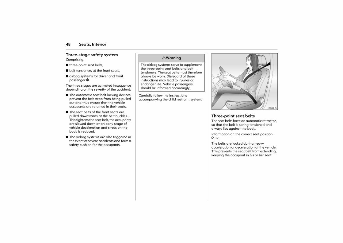
Picture no: 18531s.tifThree-point seat belts The seat belts have an automatic retractor, so that the belt is spring tensioned and always lies against the body.
Information on the correct seat position 3 39.
The belts are locked during heavy acceleration or deceleration of the vehicle. This prevents the seat belt from extending, keeping the occupant in his or her seat.
9 Warning
The airbag systems serve to supplement the three-point seat belts and belt tensioners. The seat belts must therefore always be worn. Disregard of these instructions may lead to injuries or endanger life. Vehicle passengers should be informed accordingly.
49Seats, Interior
Seat belts are only designed for use by one person at a time. They are not suitable for persons younger than 12 years of age or smaller than 150 cm.
For children up to 12 years of age, we recommend the Opel child restraint system 3 53.
Checking the seat belts From time to time, check the functionality of all seat belt system components and check for damage. Have damaged components replaced. Have seat belts and deployed belt tensioners replaced in a workshop after an accident.
Make sure that seat belts are not damaged or trapped by sharp objects.
9 Warning
Fasten your seat belt before each trip. In the event of an accident, persons not wearing seat belts endanger their fellow occupants and themselves.
50 Seats, Interior
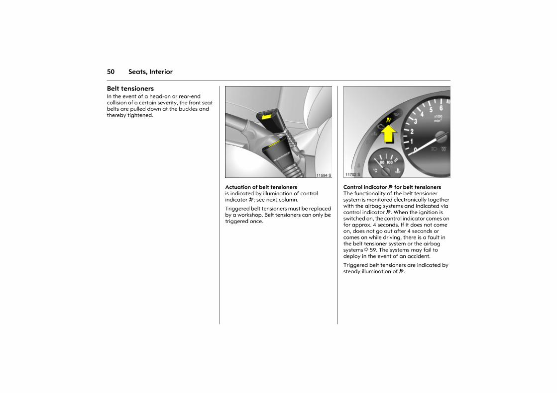
Belt tensioners In the event of a head-on or rear-end collision of a certain severity, the front seat belts are pulled down at the buckles and thereby tightened.
Picture no: 11594s.tifActuation of belt tensioners is indicated by illumination of control indicator v; see next column.
Triggered belt tensioners must be replaced by a workshop. Belt tensioners can only be triggered once.
Picture no: 11702s.tifControl indicator v for belt tensioners The functionality of the belt tensioner system is monitored electronically together with the airbag systems and indicated via control indicator v. When the ignition is switched on, the control indicator comes on for approx. 4 seconds. If it does not come on, does not go out after 4 seconds or comes on while driving, there is a fault in the belt tensioner system or the airbag systems 3 59. The systems may fail to deploy in the event of an accident.
Triggered belt tensioners are indicated by steady illumination of v.
51Seats, Interior
The system�s integrated self-diagnostics allows faults to be quickly remedied.
Important z Do not affix or place accessories or other
objects within the deployment zone of the belt tensioners (in the area of the belt buckle). Do not make any modifications to belt tensioner components and the inertia real device because this will invalidate the vehicle type approval.
z The belt tensioner and airbag system control electronics can be found in the centre console area. In order to avoid malfunctions, do not store magnetic objects in this area.
z When using the rear seat, make sure that the components of the front seat belt are not damaged by shoes or other objects. Not dirt must get into the inertia reel of the seat belt.
z We recommend that you have the seats removed by a workshop.
z The belt tensioners only deploy once, which can be detected by illumination of the control indicator v. Have deployed belt tensioners replaced by a workshop.
z The applicable safety regulations must be adhered to when the vehicle is disposed of. The vehicle should therefore be disposed of by a recycling company.
9 Warning
Have cause of fault remedied immediately by a workshop.
9 Warning
Incorrect handling (e.g. removal or fitting of seat belts or belt buckles) can cause the belt tensioners to deploy, with risk of injury.
52 Seats, Interior
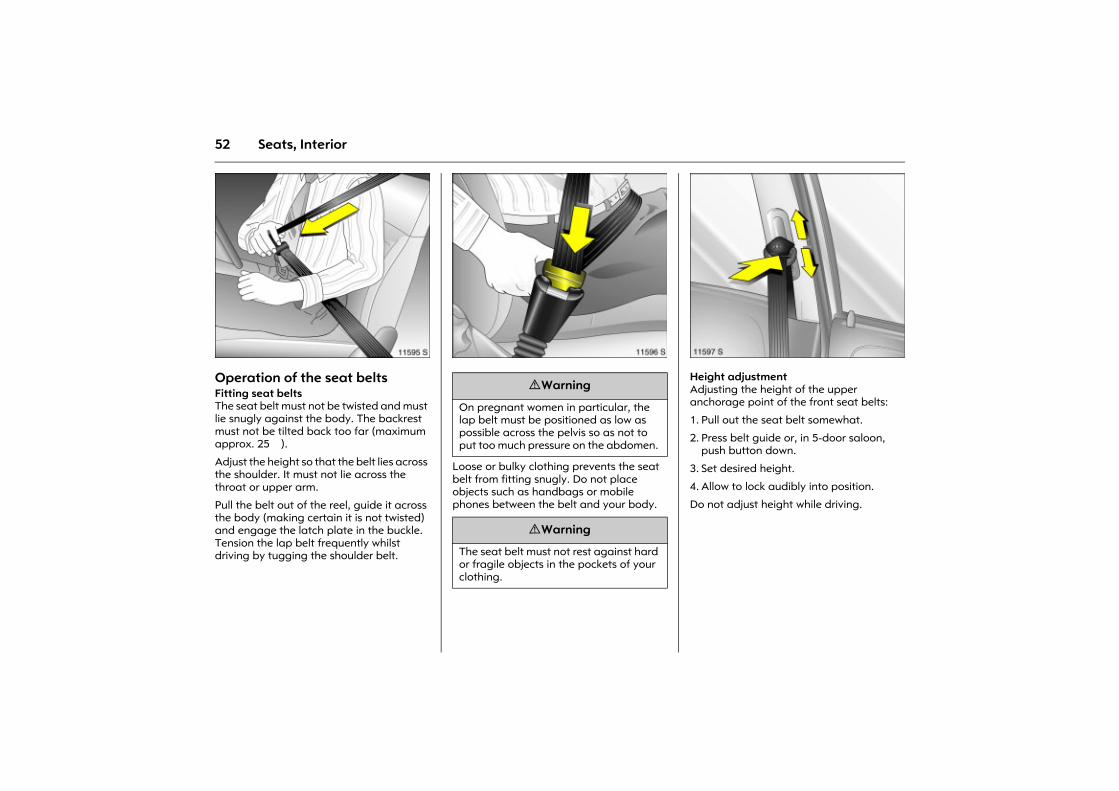
Picture no: 11595s.tifOperation of the seat belts Fitting seat belts The seat belt must not be twisted and must lie snugly against the body. The backrest must not be tilted back too far (maximum approx. 25�).
Adjust the height so that the belt lies across the shoulder. It must not lie across the throat or upper arm.
Pull the belt out of the reel, guide it across the body (making certain it is not twisted) and engage the latch plate in the buckle. Tension the lap belt frequently whilst driving by tugging the shoulder belt.
Picture no: 11596s.tif
Loose or bulky clothing prevents the seat belt from fitting snugly. Do not place objects such as handbags or mobile phones between the belt and your body.
Picture no: 11597s.tifHeight adjustment Adjusting the height of the upper anchorage point of the front seat belts:
1. Pull out the seat belt somewhat.
2. Press belt guide or, in 5-door saloon, push button down.
3. Set desired height.
4. Allow to lock audibly into position.
Do not adjust height while driving.
9 Warning
On pregnant women in particular, the lap belt must be positioned as low as possible across the pelvis so as not to put too much pressure on the abdomen.
9 Warning
The seat belt must not rest against hard or fragile objects in the pockets of your clothing.
53Seats, Interior
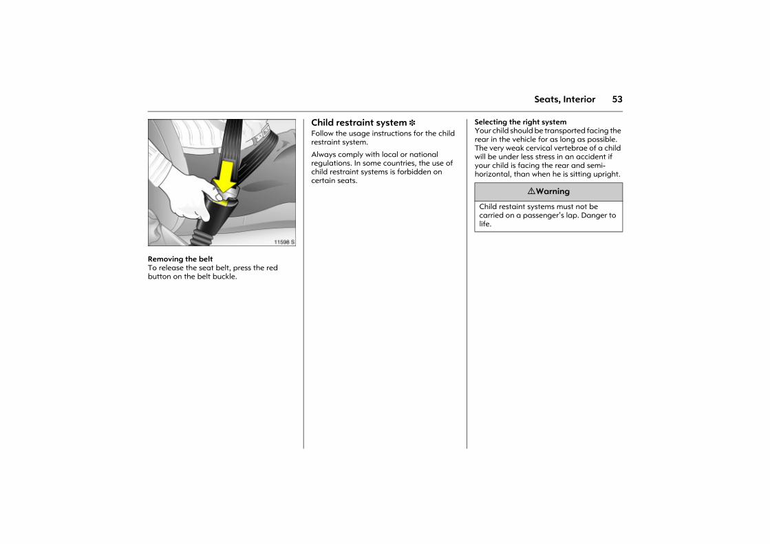
Picture no: 11598s.tifRemoving the belt To release the seat belt, press the red button on the belt buckle.
Child restraint system 3 Follow the usage instructions for the child restraint system.
Always comply with local or national regulations. In some countries, the use of child restraint systems is forbidden on certain seats.
Selecting the right system Your child should be transported facing the rear in the vehicle for as long as possible. The very weak cervical vertebrae of a child will be under less stress in an accident if your child is facing the rear and semi-horizontal, than when he is sitting upright.
9 Warning
Child restaint systems must not be carried on a passenger�s lap. Danger to life.
54 Seats, Interior
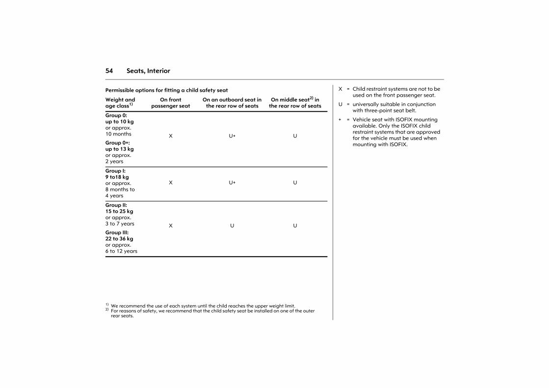
Permissible options for fitting a child safety seat
Weight and age class1)
1) We recommend the use of each system until the child reaches the upper weight limit.
On front passenger seat
On an outboard seat in the rear row of seats
On middle seat2) in the rear row of seats
2) For reasons of safety, we recommend that the child safety seat be installed on one of the outer rear seats.
Group 0: up to 10 kg or approx. 10 months
Group 0+: up to 13 kg or approx. 2 years
X U+ U
Group I: 9 to18 kg or approx. 8 months to 4 years
X U+ U
Group II: 15 to 25 kg or approx. 3 to 7 years
Group III: 22 to 36 kg or approx. 6 to 12 years
X U U
X = Child restraint systems are not to be used on the front passenger seat.
U = universally suitable in conjunction with three-point seat belt.
+ = Vehicle seat with ISOFIX mounting available. Only the ISOFIX child restraint systems that are approved for the vehicle must be used when mounting with ISOFIX.
55Seats, Interior
Note z Children under 12 years of age or 150 cm
must only travel in an appropriate child restraint system on the seats in the rear row 3.
z When transporting children, use the child restraint systems suitable for the child�s weight.
z Be sure that child restraint systems are properly installed - see the instructions accompanying the child restraint system.
z The covers of the Opel child restraint system can be wiped clean.
z Do not stick anything on the child restraint systems and do not cover them with any other materials.
z Only allow the child to enter and exit on the side of the vehicle facing away from the road.
z A child restraint system which has been subjected to stress in an accident must be replaced.
z Secure or remove child restraint systems that are in the vehicle but not in use.
Mounting clips 3 for ISOFIX child restraint systems The mounting eyes for the ISOFIX child restraint system are located on the rear, outer seats 3 between the seat back and the seat cushion.
Fasten permitted ISOFIX child restraint systems to the mounting brackets.
Closely follow the installation instructions accompanying the ISOFIX child restraint system.
56 Seats, Interior
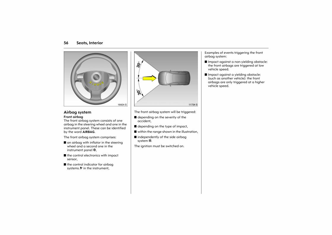
Picture no: 16424s.tifAirbag system Front airbag The front airbag system consists of one airbag in the steering wheel and one in the instrument panel. These can be identified by the word AIRBAG.
The front airbag system comprises:
z an airbag with inflator in the steering wheel and a second one in the instrument panel 3,
z the control electronics with impact sensor,
z the control indicator for airbag systems v in the instrument,
Picture no: 11734s.tifThe front airbag system will be triggered:
z depending on the severity of the accident,
z depending on the type of impact,
z within the range shown in the illustration,
z independently of the side airbag system 3.
The ignition must be switched on.
Examples of events triggering the front airbag system:
z Impact against a non-yielding obstacle: the front airbags are triggered at low vehicle speed.
z Impact against a yielding obstacle:(such as another vehicle): the front airbags are only triggered at a higher vehicle speed.

57Seats, Interior
Picture no: 11600s.tifWhen triggered, the front airbags inflate in milliseconds to form a safety cushion for the driver and front passenger. The forward movement of the front seat occupants is checked, thereby substantially reducing the risk of injury to the upper body and head.
No impairment of view will occur, because the airbags inflate and deflate so quickly that it is often not even noticed in an accident.
Picture no: 18530s.tif Picture no: 18531s.tifThe front airbag system will not be triggered in the event of z the ignition is switched off,
z minor frontal collisions,
z accidents in which the vehicle overturns,
z collisions involving a side or rear impact,
that is to say, if it would not be of benefit to the occupants.
9 Warning
Optimum protection is only provided with the seat in the proper position 3 39. Keep the area in which the airbag inflates clear of obstructions. Wear the three-point seat belt properly fastened. The front airbag system is an additional safety device, not a replacement for your seat belt.
58 Seats, Interior
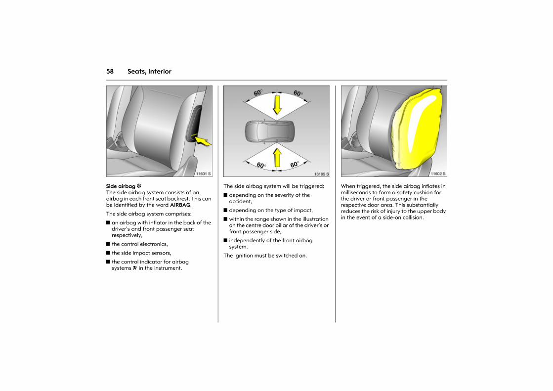
Picture no: 11601s.tifSide airbag 3 The side airbag system consists of an airbag in each front seat backrest. This can be identified by the word AIRBAG.
The side airbag system comprises:
z an airbag with inflator in the back of the driver�s and front passenger seat respectively,
z the control electronics,
z the side impact sensors,
z the control indicator for airbag systems v in the instrument.
Picture no: 13195s.tifThe side airbag system will be triggered:
z depending on the severity of the accident,
z depending on the type of impact,
z within the range shown in the illustration on the centre door pillar of the driver�s or front passenger side,
z independently of the front airbag system.
The ignition must be switched on.
Picture no: 11602s.tifWhen triggered, the side airbag inflates in milliseconds to form a safety cushion for the driver or front passenger in the respective door area. This substantially reduces the risk of injury to the upper body in the event of a side-on collision.
59Seats, Interior
The side airbags will not be triggered in the event of
z the ignition is switched off,
z frontal collisions,
z accidents in which the vehicle overturns,
z collisions involving a rear impact,
z collisions involving a side impact outside the passenger cell. Picture no: 11702s.tif
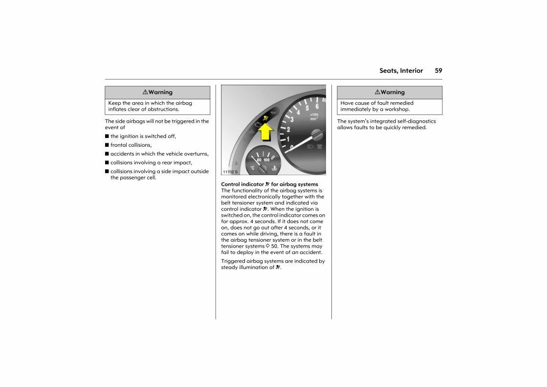
Control indicator v for airbag systemsThe functionality of the airbag systems is monitored electronically together with the belt tensioner system and indicated via control indicator v. When the ignition is switched on, the control indicator comes on for approx. 4 seconds. If it does not come on, does not go out after 4 seconds, or it comes on while driving, there is a fault in the airbag tensioner system or in the belt tensioner systems 3 50. The systems may fail to deploy in the event of an accident.
Triggered airbag systems are indicated by steady illumination of v.
The system�s integrated self-diagnostics allows faults to be quickly remedied.
9 Warning
Keep the area in which the airbag inflates clear of obstructions.
9 Warning
Have cause of fault remedied immediately by a workshop.
60 Seats, Interior
Important
z No objects or accessories must be placed in the area in which the airbags inflate, as they could cause injury when the components are deployed.
z Do not place any objects between the airbag systems and the vehicle occupants. Danger of injury. Do not install a child restraint system 3 on the front passenger seat. Danger to life.
z Use the hooks in the roof frame only to hang up light articles of clothing or coat hangers. Do not place any objects in the pockets of the hanging items � risk of injury.
z The airbag systems and belt tensioner control electronics can be found in the centre console area. In order to avoid malfunctions, do not store magnetic objects in this area.
z Do not stick anything on the steering wheel, instrumnet panel or front seat backrests in the vicinity of the airbags. Do not cover any of these areas with other materials.
z Use only a dry cloth or interior cleaner to clean the steering wheel, instrument panel and front seat backrests. Do not use any aggressive cleaning agents.
z Only protective covers which are approved for your vehicle with side airbag may be fitted on the front seats. When fitting the protective covers, make sure that the airbag units on the outboard sides of the front seat backrests are not covered.
z The airbag systems are triggered independently of one another depending on the severity of the accident and type of impact.
z Each airbag is only deployed once. Have deployed airbags replaced by a workshop immediately.
z The speeds, directions of movement and deformation properties of the vehicles, and the properties of the obstacle concerned, determine the severity of the accident and triggering of the airbags. The degree of damage to your vehicle and the resulting repair costs alone are not indicative that the criteria for triggering of the airbags were met.
z Do not perform any alterations on the components of the airbag system, as this would render the vehicle unroadworthy.
z We recommend having the steering wheel, the instrument panel, all panelling parts, the door seals, the handles and the seats removed by a workshop.
z The applicable safety regulations must be adhered to when the vehicle is disposed of. The vehicle should therefore be disposed of by a recycling company.
z Anyone weighing less than 35 kg should seat in the rear seat.
9 Warning
As with any other object, child restaint systems must not be carried on a passenger�s lap. Danger to life.
9 Warning
If handled improperly the airbag systems can be triggered in an explosive manner � risk of injury!
61Seats, Interior
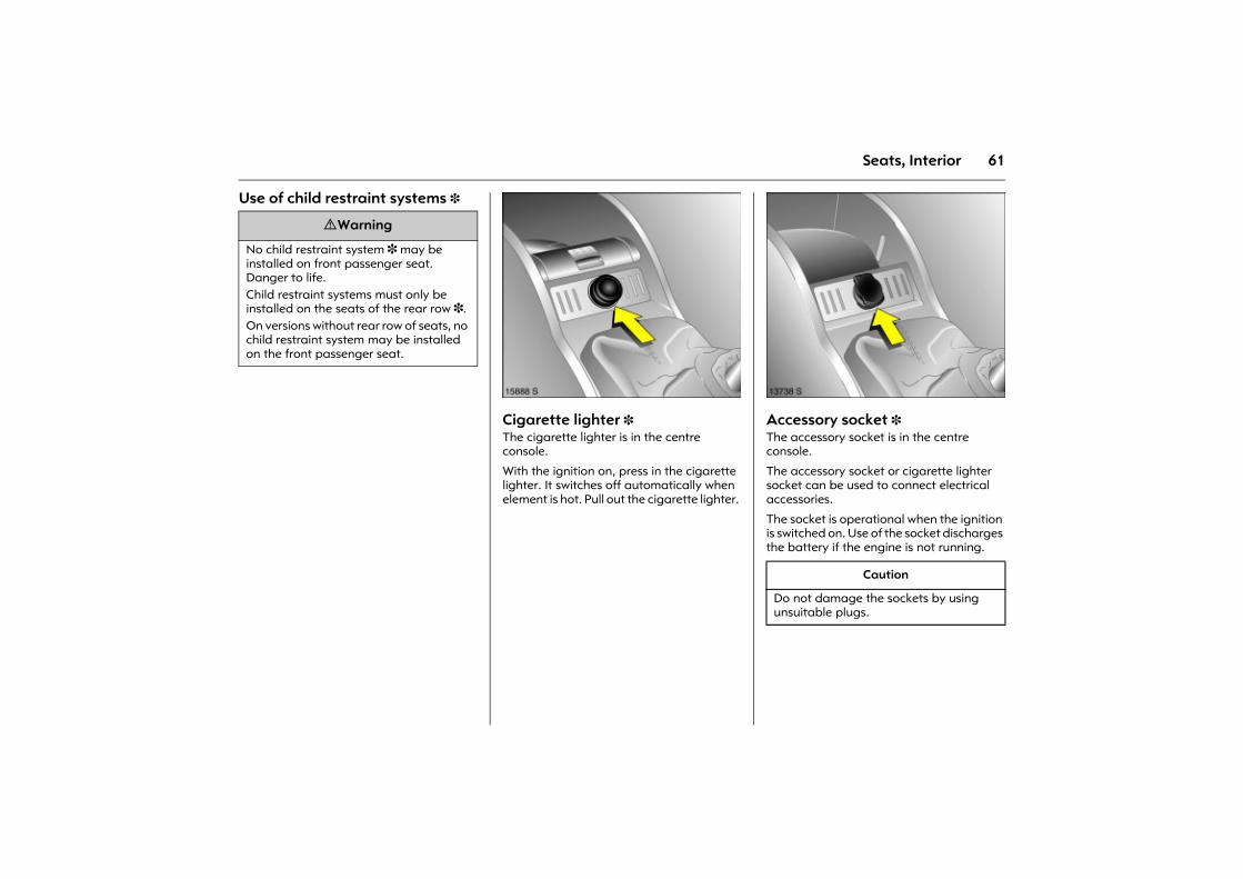
Use of child restraint systems 3
Picture no: 15888s.tifCigarette lighter 3 The cigarette lighter is in the centre console.
With the ignition on, press in the cigarette lighter. It switches off automatically when element is hot. Pull out the cigarette lighter.
Picture no: 13738s.tifAccessory socket 3 The accessory socket is in the centre console.
The accessory socket or cigarette lighter socket can be used to connect electrical accessories.
The socket is operational when the ignition is switched on. Use of the socket discharges the battery if the engine is not running.
9 Warning
No child restraint system 3 may be installed on front passenger seat. Danger to life.Child restraint systems must only be installed on the seats of the rear row 3. On versions without rear row of seats, no child restraint system may be installed on the front passenger seat.
Caution
Do not damage the sockets by using unsuitable plugs.
62 Seats, Interior
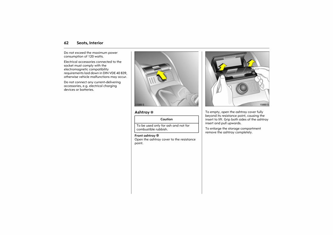
Do not exceed the maximum power consumption of 120 watts.
Electrical accessories connected to the socket must comply with the electromagnetic compatibility requirements laid down in DIN VDE 40 839, otherwise vehicle malfunctions may occur.
Do not connect any current-delivering accessories, e.g. electrical charging devices or batteries.
Picture no: 11589s.tifAshtray 3
Front ashtray 3 Open the ashtray cover to the resistance point.
Picture no: 15889s.tifTo empty, open the ashtray cover fully beyond its resistance point, causing the insert to lift. Grip both sides of the ashtray insert and pull upwards.
To enlarge the storage compartment remove the ashtray completely.
Caution
To be used only for ash and not for combustible rubbish.
63Seats, Interior
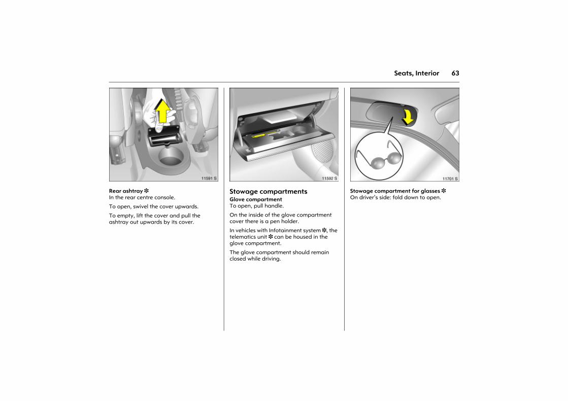
Picture no: 11591s.tifRear ashtray 3 In the rear centre console.
To open, swivel the cover upwards.
To empty, lift the cover and pull the ashtray out upwards by its cover.
Picture no: 11592s.tifStowage compartments Glove compartment To open, pull handle.
On the inside of the glove compartment cover there is a pen holder.
In vehicles with Infotainment system 3, the telematics unit 3 can be housed in the glove compartment.
The glove compartment should remain closed while driving.
Picture no: 11701s.tifStowage compartment for glasses 3 On driver�s side: fold down to open.
64 Seats, Interior
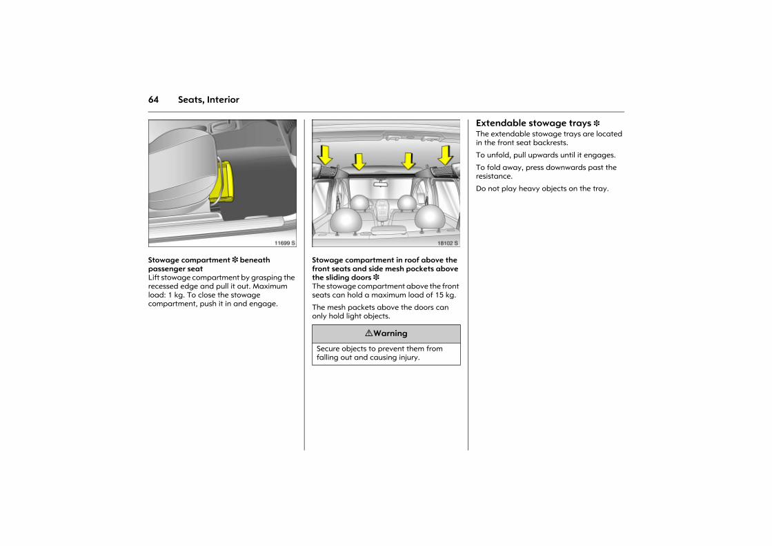
Picture no: 11699s.tifStowage compartment 3 beneath passenger seat Lift stowage compartment by grasping the recessed edge and pull it out. Maximum load: 1 kg. To close the stowage compartment, push it in and engage.
Picture no: 18102s.tifStowage compartment in roof above the front seats and side mesh pockets above the sliding doors 3 The stowage compartment above the front seats can hold a maximum load of 15 kg.
The mesh packets above the doors can only hold light objects.
Extendable stowage trays 3 The extendable stowage trays are located in the front seat backrests.
To unfold, pull upwards until it engages.
To fold away, press downwards past the resistance.
Do not play heavy objects on the tray.
9 Warning
Secure objects to prevent them from falling out and causing injury.
65Seats, Interior
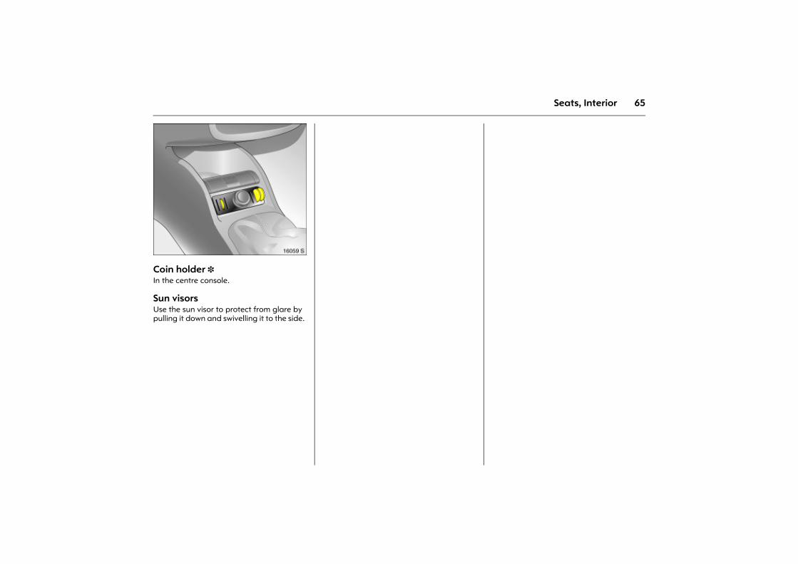
Picture no: 16059s.tifCoin holder 3 In the centre console.
Sun visors Use the sun visor to protect from glare by pulling it down and swivelling it to the side.
66 Instruments
Instruments
Control indicators ................................ 66 Instrument display............................... 71 Information display ............................. 76 Warning buzzers.................................. 82 Windscreen wipers............................... 82
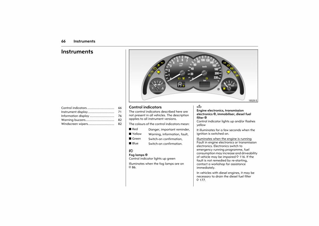
Picture no: 18529s.tifControl indicators The control indicators described here are not present in all vehicles. The description applies to all instrument versions.
The colours of the control indicators mean:
> Fog lamps 3 Control indicator lights up green
Illuminates when the fog lamps are on 3 86.
Picture no: A Engine electronics, transmission electronics 3, immobiliser, diesel fuel filter 3 Control indicator lights up and/or flashes yellow
It illuminates for a few seconds when the ignition is switched on.
Illuminates when the engine is runningFault in engine electronics or transmission electronics. Electronics switch to emergency running programme, fuel consumption may increase and driveability of vehicle may be impaired 3 116. If the fault is not remedied by re-starting, contact a workshop for assistance immediately.
In vehicles with diesel engines, it may be necessary to drain the diesel fuel filter 3 177.
z Red Danger, important reminder,z Yellow Warning, information, fault,z Green Switch-on confirmation,z Blue Switch-on confirmation.
67Instruments
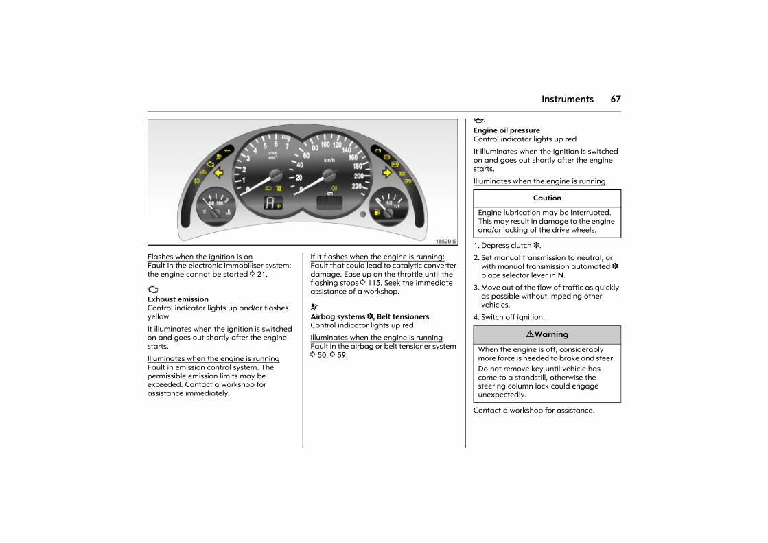
Picture no: 18529s.tifFlashes when the ignition is onFault in the electronic immobiliser system; the engine cannot be started 3 21.
Z Exhaust emission Control indicator lights up and/or flashes yellow
It illuminates when the ignition is switched on and goes out shortly after the engine starts.
Illuminates when the engine is runningFault in emission control system. The permissible emission limits may be exceeded. Contact a workshop for assistance immediately.
Picture no: If it flashes when the engine is running:Fault that could lead to catalytic converter damage. Ease up on the throttle until the flashing stops 3 115. Seek the immediate assistance of a workshop.
v Airbag systems 3, Belt tensioners Control indicator lights up red
Illuminates when the engine is runningFault in the airbag or belt tensioner system 3 50, 3 59.
I Engine oil pressure Control indicator lights up red
It illuminates when the ignition is switched on and goes out shortly after the engine starts.
Illuminates when the engine is running
1. Depress clutch 3.
2. Set manual transmission to neutral, or with manual transmission automated 3 place selector lever in N.
3. Move out of the flow of traffic as quickly as possible without impeding other vehicles.
4. Switch off ignition.
Contact a workshop for assistance.
Caution
Engine lubrication may be interrupted. This may result in damage to the engine and/or locking of the drive wheels.
9 Warning
When the engine is off, considerably more force is needed to brake and steer. Do not remove key until vehicle has come to a standstill, otherwise the steering column lock could engage unexpectedly.
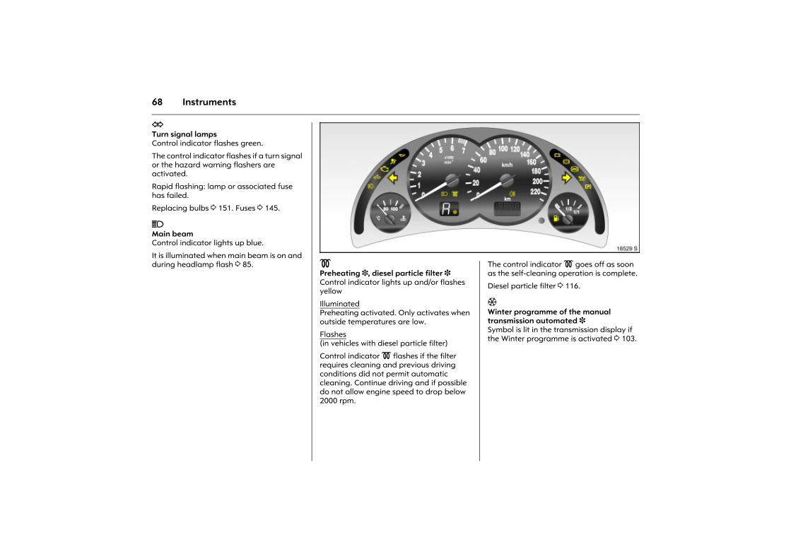
68 Instruments
O Turn signal lamps Control indicator flashes green.
The control indicator flashes if a turn signal or the hazard warning flashers are activated.
Rapid flashing: lamp or associated fuse has failed.
Replacing bulbs 3 151. Fuses 3 145.
C Main beam Control indicator lights up blue.
It is illuminated when main beam is on and during headlamp flash 3 85.
Picture no: 18529s.tif! Preheating 3, diesel particle filter 3 Control indicator lights up and/or flashes yellow
IlluminatedPreheating activated. Only activates when outside temperatures are low.
Flashes (in vehicles with diesel particle filter)
Control indicator ! flashes if the filter requires cleaning and previous driving conditions did not permit automatic cleaning. Continue driving and if possible do not allow engine speed to drop below 2000 rpm.
Picture no: The control indicator ! goes off as soon as the self-cleaning operation is complete.
Diesel particle filter 3 116.
T Winter programme of the manual transmission automated 3 Symbol is lit in the transmission display if the Winter programme is activated 3 103.
69Instruments
r Fog tail lamp Control indicator lights up yellow.
Illuminates when the fog tail lamp is on 3 86.
p Alternator Control indicator lights up red
It illuminates when the ignition is switched on and goes out shortly after the engine starts.
Illuminates when the engine is runningStop and turn engine off. battery is not charged. Engine cooling may be interrupted. Contact a workshop.
R Brake system, clutch system 3 Control indicator lights up or flashes red.
IlluminatedIlluminates when the ignition is switched on if the hand brake is applied 3 120.
Illuminates when the hand brake is released if the fluid level for the brake or clutch system 3 is low 3 179.
FlashesOn vehicles with manual transmission automated 3, control indicator R flashes for a few seconds after the ignition is switched off if the hand brake has not been applied.
u Anti-lock Braking System 3 Control indicator lights up red
Illuminates while drivingFault in the anti-lock braking system 3 119.
9 Warning
Stop. Do not continue your journey. Consult a workshop.
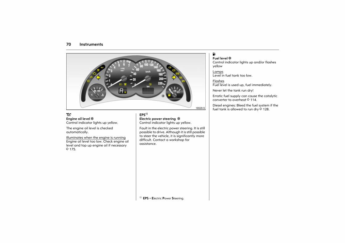
70 Instruments
Picture no: 18529s.tifS Engine oil level 3 Control indicator lights up yellow.
The engine oil level is checked automatically.
Illuminates when the engine is runningEngine oil level too low. Check engine oil level and top up engine oil if necessary 3 175.
Picture no: EPS1) Electric power steering 3 Control indicator lights up yellow.
Fault in the electric power steering. It is still possible to drive. Although it is still possible to steer the vehicle, it is significantly more difficult. Contact a workshop for assistance.
1) EPS = Electric Power Steering.
Y Fuel level 3 Control indicator lights up and/or flashes yellow
Lamps Level in fuel tank too low.
FlashesFuel level is used up, fuel immediately.
Never let the tank run dry!
Erratic fuel supply can cause the catalytic converter to overheat 3 114.
Diesel engines: Bleed the fuel system if the fuel tank is allowed to run dry 3 128.
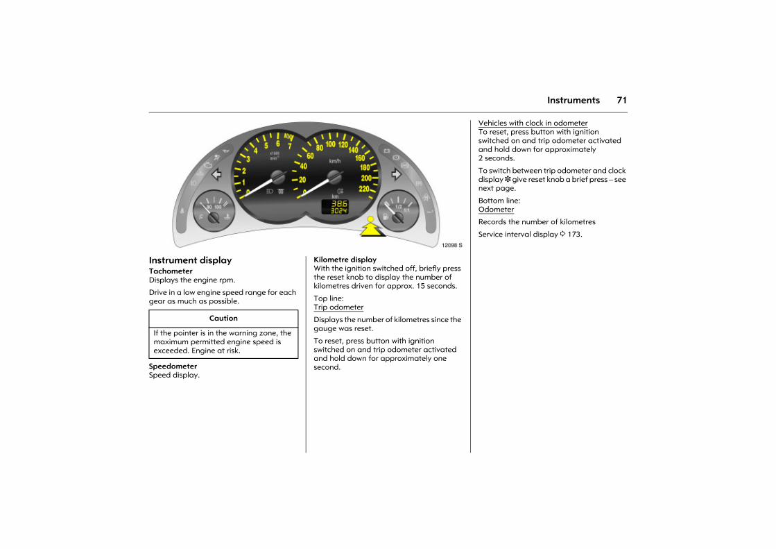
71Instruments
Picture no: 12098s.tif.Instrument displayTachometerDisplays the engine rpm.
Drive in a low engine speed range for each gear as much as possible.
Speedometer Speed display.
Picture no: Kilometre display With the ignition switched off, briefly press the reset knob to display the number of kilometres driven for approx. 15 seconds.
Top line:Trip odometer
Displays the number of kilometres since the gauge was reset.
To reset, press button with ignition switched on and trip odometer activated and hold down for approximately one second.
Caution
If the pointer is in the warning zone, the maximum permitted engine speed is exceeded. Engine at risk.
Vehicles with clock in odometerTo reset, press button with ignition switched on and trip odometer activated and hold down for approximately 2 seconds.
To switch between trip odometer and clock display 3 give reset knob a brief press � see next page.
Bottom line:Odometer
Records the number of kilometres
Service interval display 3 173.

72 Instruments
Picture no: 12099s.tif.Time display in odometer 3 To switch between trip odometer and time display 3 give reset knob a short press.
When the vehicle lights are on, the brightness of the display can be adjusted using the right-hand adjuster wheel k below the light switch 3 87.
Setting the time On the clock display, press the setting knob on the instrument for approx. 2 seconds. The flashing value is set by pressing briefly. Press for about 2 seconds again to switch to the next setting and at the end to exit setting mode.
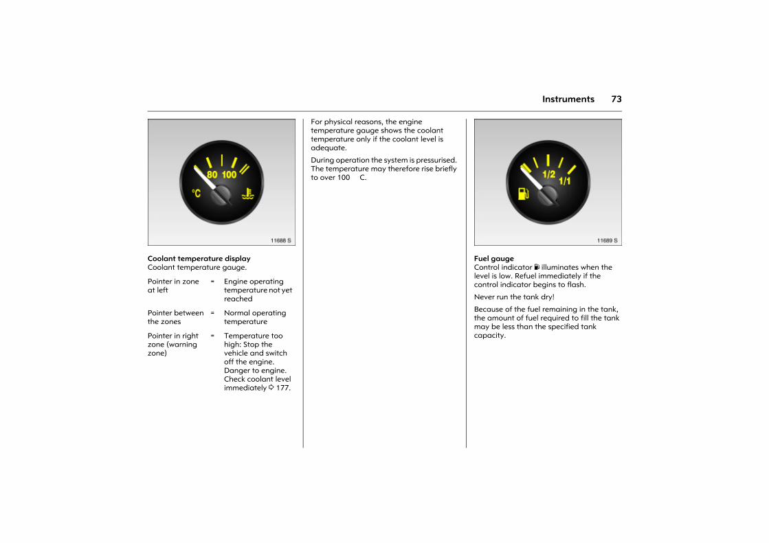
73Instruments
Picture no: 11688s.tifCoolant temperature displayCoolant temperature gauge.
For physical reasons, the engine temperature gauge shows the coolant temperature only if the coolant level is adequate.
During operation the system is pressurised. The temperature may therefore rise briefly to over 100 �C.
Picture no: 11689s.tifFuel gauge
Control indicator Y illuminates when the level is low. Refuel immediately if the control indicator begins to flash.
Never run the tank dry!
Because of the fuel remaining in the tank, the amount of fuel required to fill the tank may be less than the specified tank capacity.
Pointer in zone at left
= Engine operating temperature not yet reached
Pointer between the zones
= Normal operating temperature
Pointer in right zone (warning zone)
= Temperature too high: Stop the vehicle and switch off the engine. Danger to engine. Check coolant level immediately 3 177.
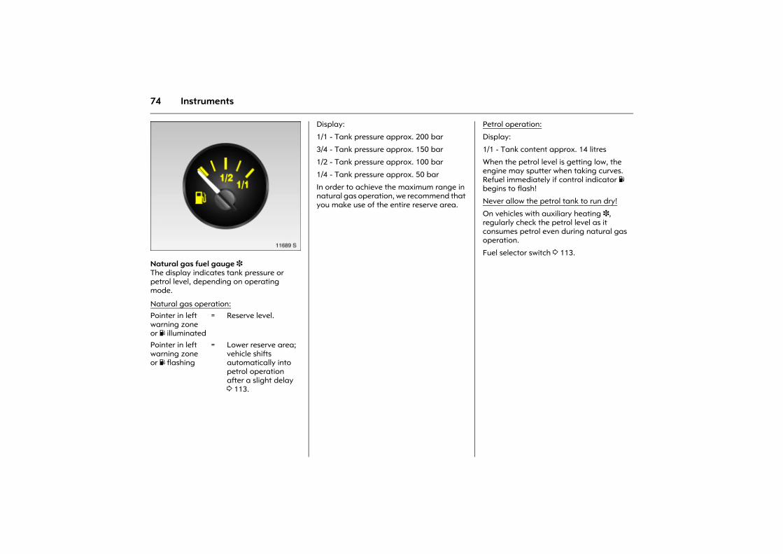
74 Instruments
Picture no: 11689s.tifNatural gas fuel gauge 3 The display indicates tank pressure or petrol level, depending on operating mode.
Display:
1/1 - Tank pressure approx. 200 bar
3/4 - Tank pressure approx. 150 bar
1/2 - Tank pressure approx. 100 bar
1/4 - Tank pressure approx. 50 bar
In order to achieve the maximum range in natural gas operation, we recommend that you make use of the entire reserve area.
Petrol operation:
Display:
1/1 - Tank content approx. 14 litres
When the petrol level is getting low, the engine may sputter when taking curves. Refuel immediately if control indicator Y begins to flash!
Never allow the petrol tank to run dry!
On vehicles with auxiliary heating 3, regularly check the petrol level as it consumes petrol even during natural gas operation.
Fuel selector switch 3 113.
Natural gas operation:Pointer in left warning zone or Y illuminated
= Reserve level.
Pointer in left warning zone or Y flashing
= Lower reserve area; vehicle shifts automatically into petrol operation after a slight delay 3 113.
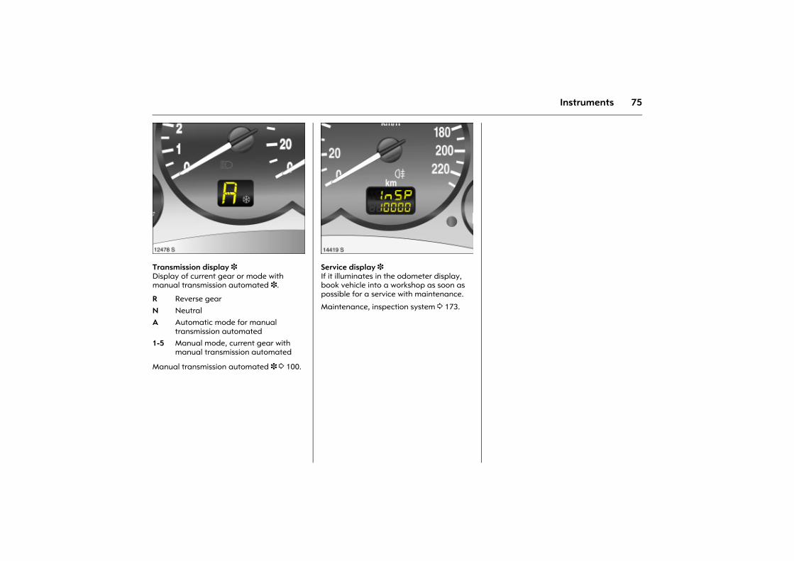
75Instruments
Picture no: 12478s.tifTransmission display 3 Display of current gear or mode with manual transmission automated 3.
Manual transmission automated 3 3 100.
Picture no: 14419s.tifService display 3 If it illuminates in the odometer display, book vehicle into a workshop as soon as possible for a service with maintenance.
Maintenance, inspection system 3 173.R Reverse gearN Neutral A Automatic mode for manual
transmission automated1-5 Manual mode, current gear with
manual transmission automated
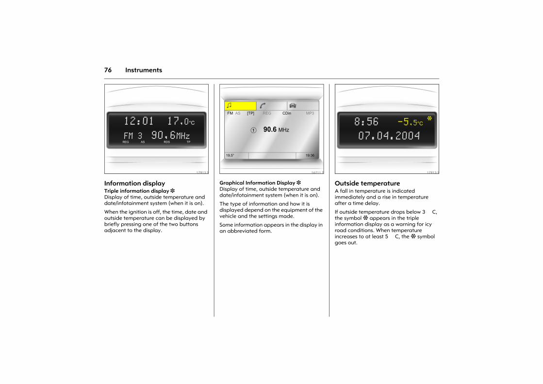
76 Instruments
Picture no: 17913s.tifInformation display Triple information display 3 Display of time, outside temperature and date/infotainment system (when it is on).
When the ignition is off, the time, date and outside temperature can be displayed by briefly pressing one of the two buttons adjacent to the display.
Picture no: 16711t.tifGraphical Information Display 3 Display of time, outside temperature and date/infotainment system (when it is on).
The type of information and how it is displayed depend on the equipment of the vehicle and the settings made.
Some information appears in the display in an abbreviated form.
Picture no: 17913s.tifOutside temperature A fall in temperature is indicated immediately and a rise in temperature after a time delay.
If outside temperature drops below 3 �C, the symbol : appears in the triple information display as a warning for icy road conditions. When temperature increases to at least 5 �C, the : symbol goes out.
12:01 17,0°C
FM 3 90,6MHzREG AS RDS TP
FM AS [TP] REG CDin MP3
� 90.6 MHz
19,5° 19:36
8:56 -5,5°C
07.04.2004
:
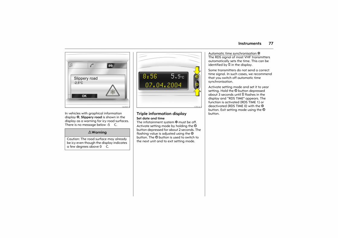
77Instruments
Picture no: 16707t.tifIn vehicles with graphical information display 3, Slippery road is shown in the display as a warning for icy road surfaces. There is no message below -5 �C.
Picture no: 17914s.tifTriple information display Set date and timeThe infotainment system 3 must be off. Activate setting mode by holding the Ö button depressed for about 2 seconds. The flashing value is adjusted using the ; button. The Ö button is used to switch to the next unit and to exit setting mode.
Automatic time synchronisation 3 The RDS signal of most VHF transmitters automatically sets the time. This can be identified by } in the display.
Some transmitters do not send a correct time signal. In such cases, we recommend that you switch off automatic time synchronisation.
Activate setting mode and set it to year setting. Hold the Ö button depressed about 3 seconds until } flashes in the display and �RDS TIME" appears. The function is activated (RDS TIME 1) or deactivated (RDS TIME 0) with the ; button. Exit setting mode using the Ö button.
9 Warning
Caution: The road surface may already be icy even though the display indicates a few degrees above 0 �C.
Slippery road-2,5°C
OK
8:56 5,5°C
07.04.2004
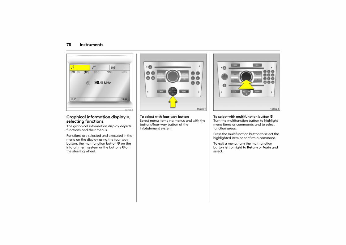
78 Instruments
Picture no: 16711t.tifGraphical information display 3, selecting functionsThe graphical information display depicts functions and their menus.
Functions are selected and executed in the menu on the display using the four-way button, the multifunction button 3 on the infotainment system or the buttons 3 on the steering wheel.
Picture no: 15593t.tifTo select with four-way buttonSelect menu items via menus and with the buttons/four-way button of the infotainment system.
Picture no: 15559t.tifTo select with multifunction button 3 Turn the multifunction button to highlight menu items or commands and to select function areas.
Press the multifunction button to select the highlighted item or confirm a command.
To exit a menu, turn the multifunction button left or right to Return or Main and select.
FM AS [TP] REG CDin MP3
� 90.6 MHz
19,5° 19:36
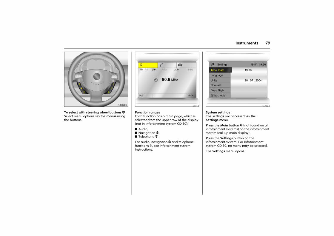
79Instruments
Picture no: 14034s.tifTo select with steering wheel buttons 3Select menu options via the menus using the buttons.
Picture no: 16711t.tifFunction ranges Each function has a main page, which is selected from the upper row of the display (not in Infotainment system CD 30):
z Audio, z Navigation 3, z Telephone 3.
For audio, navigation 3 and telephone functions 3, see infotainment system instructions.
Picture no: 16712t.tifSystem settings The settings are accessed via the Settings menu.
Press the Main button 3 (not found on all infotainment systems) on the infotainment system (call up main display).
Press the Settings button on the infotainment system. For Infotainment system CD 30, no menu may be selected.
The Settings menu opens.
FM AS [TP] REG CDin MP3
� 90.6 MHz
19,5° 19:36
7 Settings 19,5° 19:36
Time, Date 19:36
Language
Units 10 . 07 . 2004
Contrast
Day / Night
! Ign. logic
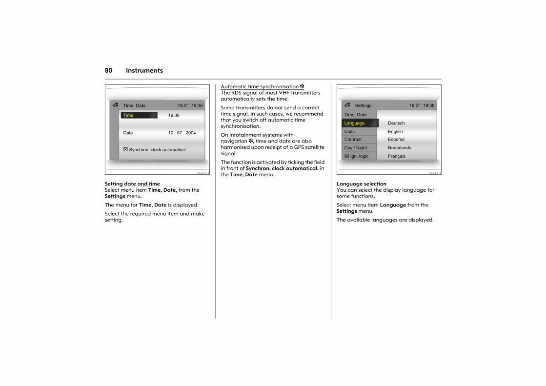
80 Instruments
Picture no: 16713t.tifSetting date and timeSelect menu item Time, Date, from the Settings menu.
The menu for Time, Date is displayed.
Select the required menu item and make setting.
Automatic time synchronisation 3 The RDS signal of most VHF transmitters automatically sets the time.
Some transmitters do not send a correct time signal. In such cases, we recommend that you switch off automatic time synchronisation.
On infotainment systems with navigation 3, time and date are also harmonised upon receipt of a GPS satellite signal.
The function is activated by ticking the field in front of Synchron. clock automatical. in the Time, Date menu.
Picture no: 16714t.tifLanguage selectionYou can select the display language for some functions.
Select menu item Language from the Settings menu.
The available languages are displayed.
7 Time, Date 19,5° 19:36
Time 19:36
Date 10 . 07 . 2004
! Synchron. clock automatical.
7 Settings 19,5° 19:36
Time, Date
Language Deutsch
Units English
Contrast Español
Day / Night Nederlands
! Ign. logic Français
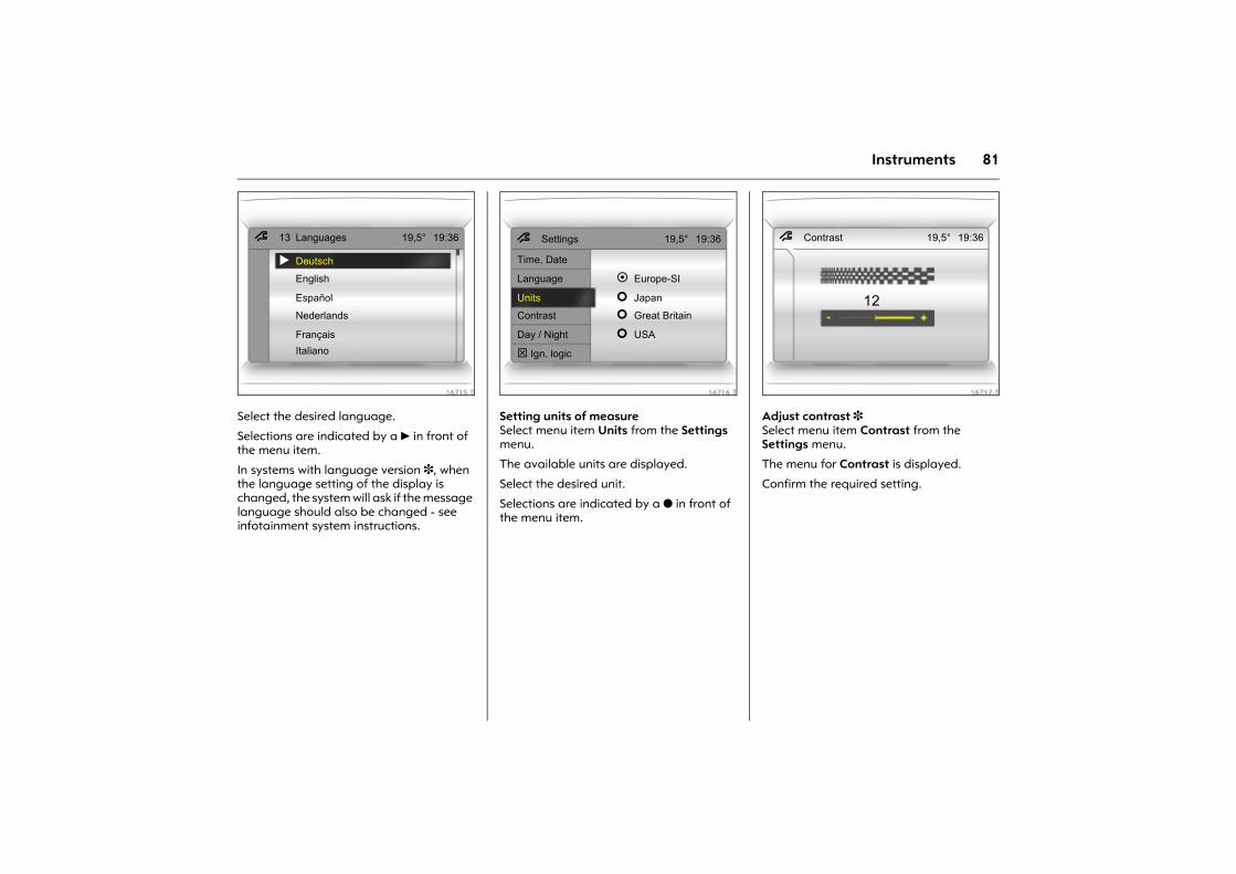
81Instruments
Picture no: 16715t.tifSelect the desired language.
Selections are indicated by a 6 in front of the menu item.
In systems with language version 3, when the language setting of the display is changed, the system will ask if the message language should also be changed - see infotainment system instructions.
Picture no: 16716t.tifSetting units of measureSelect menu item Units from the Settings menu.
The available units are displayed.
Select the desired unit.
Selections are indicated by a o in front of the menu item.
Picture no: 16717t.tifAdjust contrast 3 Select menu item Contrast from the Settings menu.
The menu for Contrast is displayed.
Confirm the required setting.
7 13 Languages 19,5° 19:36
! Deutsch
English
Español
Nederlands
FrançaisItaliano
7 Settings 19,5° 19:36
Time, Date
Language ! Europe-SI
Units " Japan
Contrast " Great Britain
Day / Night " USA
! Ign. logic
7 Contrast 19,5° 19:36
12
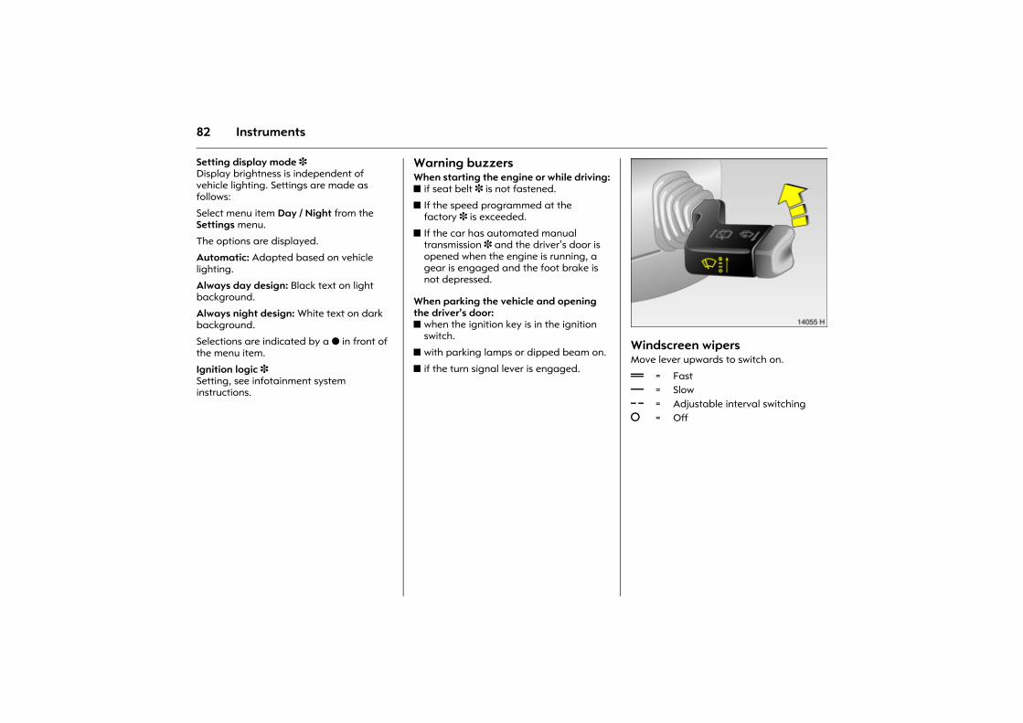
82 Instruments
Setting display mode 3 Display brightness is independent of vehicle lighting. Settings are made as follows:
Select menu item Day / Night from the Settings menu.
The options are displayed.
Automatic: Adapted based on vehicle lighting.
Always day design: Black text on light background.
Always night design: White text on dark background.
Selections are indicated by a o in front of the menu item.
Ignition logic 3 Setting, see infotainment system instructions.
Warning buzzersWhen starting the engine or while driving:z if seat belt 3 is not fastened.
z If the speed programmed at the factory 3 is exceeded.
z If the car has automated manual transmission 3 and the driver�s door is opened when the engine is running, a gear is engaged and the foot brake is not depressed.
When parking the vehicle and opening the driver�s door:z when the ignition key is in the ignition
switch.
z with parking lamps or dipped beam on.
z if the turn signal lever is engaged.
Picture no: 14055h.tifWindscreen wipers Move lever upwards to switch on.
& = Fast% = Slow $ = Adjustable interval switching§ = Off
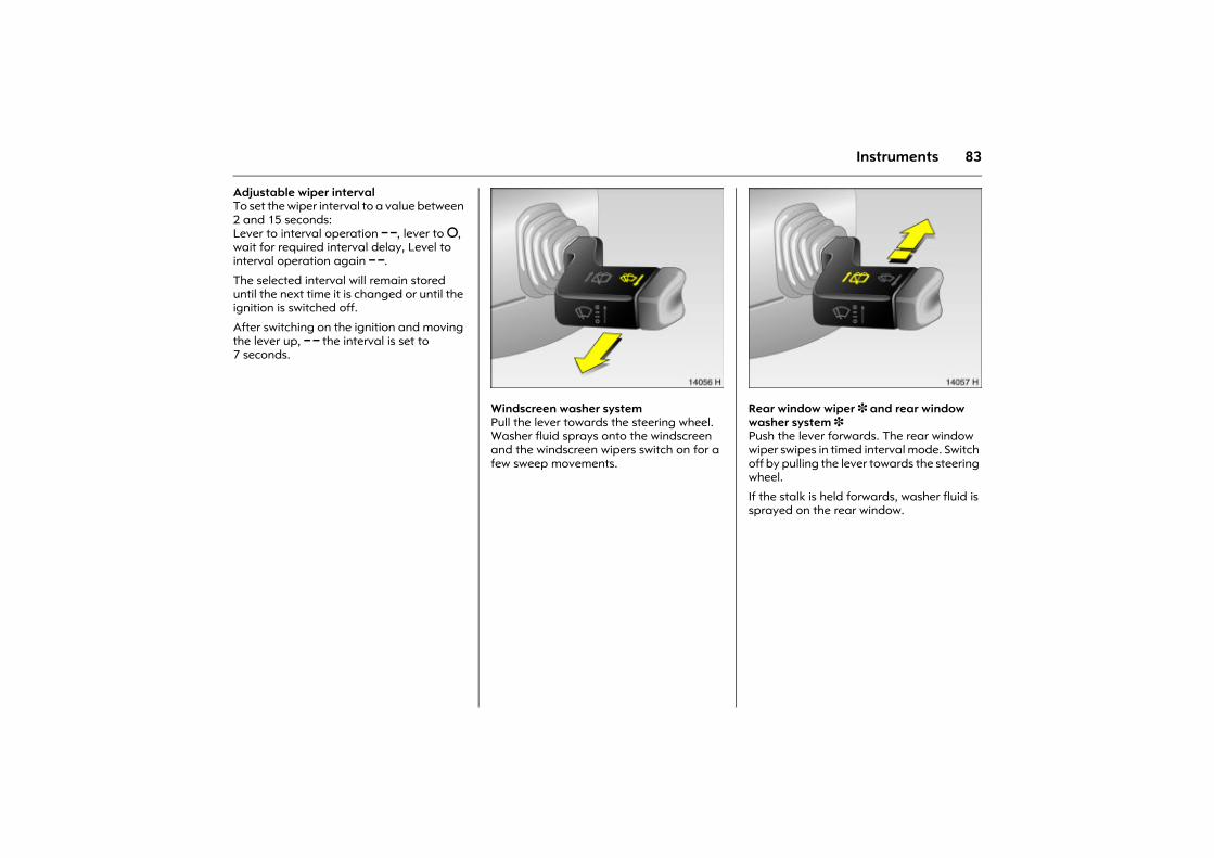
83Instruments
Adjustable wiper interval To set the wiper interval to a value between 2 and 15 seconds: Lever to interval operation $, lever to §, wait for required interval delay, Level to interval operation again $.
The selected interval will remain stored until the next time it is changed or until the ignition is switched off.
After switching on the ignition and moving the lever up, $ the interval is set to 7 seconds.
Picture no: 14056h.tifWindscreen washer system Pull the lever towards the steering wheel. Washer fluid sprays onto the windscreen and the windscreen wipers switch on for a few sweep movements.
Picture no: 14057h.tifRear window wiper 3 and rear window washer system 3 Push the lever forwards. The rear window wiper swipes in timed interval mode. Switch off by pulling the lever towards the steering wheel.
If the stalk is held forwards, washer fluid is sprayed on the rear window.
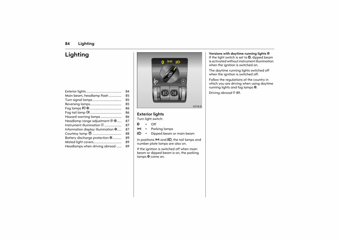
84 Lighting
Lighting
Picture no: 13718s.tifExterior lightsTurn light switch:
In positions 8 and 9, the tail lamps and number plate lamps are also on.
If the ignition is switched off when main beam or dipped beam is on, the parking lamps 3 come on.
Versions with daytime running lights 3 If the light switch is set to 7, dipped beam is activated without instrument illumination when the ignition is switched on.
The daytime running lights switched off when the ignition is switched off.
Follow the regulations of the country in which you are driving when using daytime running lights and fog lamps 3.
Driving abroad 3 89. Exterior lights ....................................... 84 Main beam, headlamp flash .............. 85 Turn signal lamps ................................ 85 Reversing lamps................................... 85 Fog lamps > 3.................................... 86 Fog tail lamp r ................................... 86 Hazard warning lamps ....................... 86 Headlamp range adjustment ? 3 ..... 87 Instrument illumination k ................... 87 Information display illumination 3..... 87 Courtesy lamp 0 ................................ 88 Battery discharge protection 3 .......... 89 Misted light covers............................... 89 Headlamps when driving abroad ...... 89
7 = Off8 = Parking lamps9 = Dipped beam or main beam
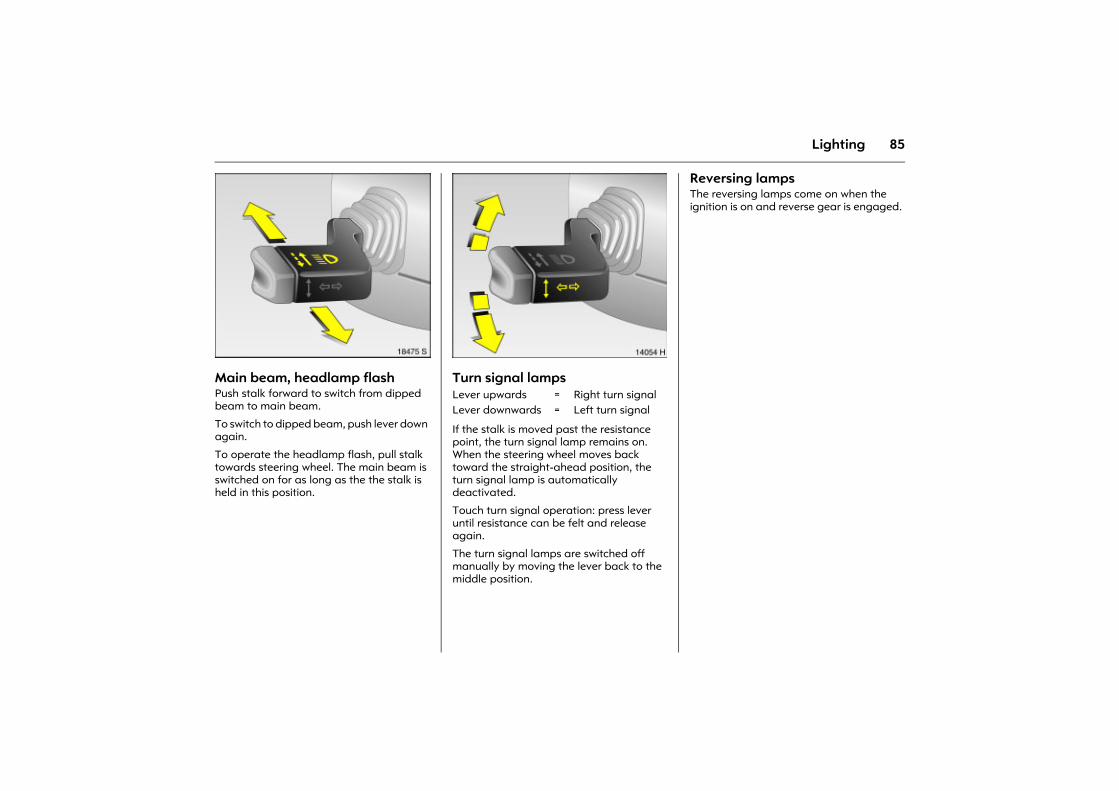
85Lighting
Picture no: 18475s.tifMain beam, headlamp flash Push stalk forward to switch from dipped beam to main beam.
To switch to dipped beam, push lever down again.
To operate the headlamp flash, pull stalk towards steering wheel. The main beam is switched on for as long as the the stalk is held in this position.
Picture no: 14054h.tifTurn signal lamps
If the stalk is moved past the resistance point, the turn signal lamp remains on. When the steering wheel moves back toward the straight-ahead position, the turn signal lamp is automatically deactivated.
Touch turn signal operation: press lever until resistance can be felt and release again.
The turn signal lamps are switched off manually by moving the lever back to the middle position.
Reversing lamps The reversing lamps come on when the ignition is on and reverse gear is engaged.
Lever upwards = Right turn signalLever downwards = Left turn signal
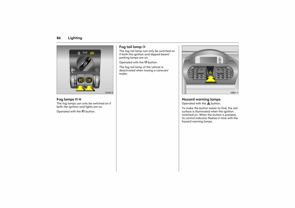
86 Lighting
Picture no: 13720s.tifFog lamps > 3 The fog lamps can only be switched on if both the ignition and lights are on.
Operated with the > button.
Fog tail lamp r The fog tail lamp can only be switched on if both the ignition and dipped beam/parking lamps are on.
Operated with the r button.
The fog tail lamp of the vehicle is deactivated when towing a caravan/trailer.
Picture no: 15865s.tifHazard warning lamps Operated with the ¨ button.
To make the button easier to find, the red surface is illuminated when the ignition switched on. When the button is pressed, its control indicator flashes in time with the hazard warning lamps.
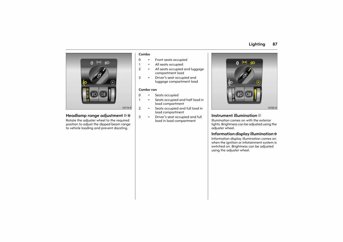
87Lighting
Picture no: 13719s.tifHeadlamp range adjustment ? 3 Rotate the adjuster wheel to the required position to adjust the dipped beam range to vehicle loading and prevent dazzling.
Combo
Combo van
Picture no: 13722s.tifInstrument illumination kIllumination comes on with the exterior lights. Brightness can be adjusted using the adjuster wheel.
Information display illumination 3 Information display illumination comes on when the ignition or infotainment system is switched on. Brightness can be adjusted using the adjuster wheel.
0 = Front seats occupied1 = All seats occupied 2 = All seats occupied and luggage
compartment load3 = Driver�s seat occupied and
luggage compartment load
0 = Seats occupied1 = Seats occupied and half load in
load compartment2 = Seats occupied and full load in
load compartment3 = Driver�s seat occupied and full
load in load compartment
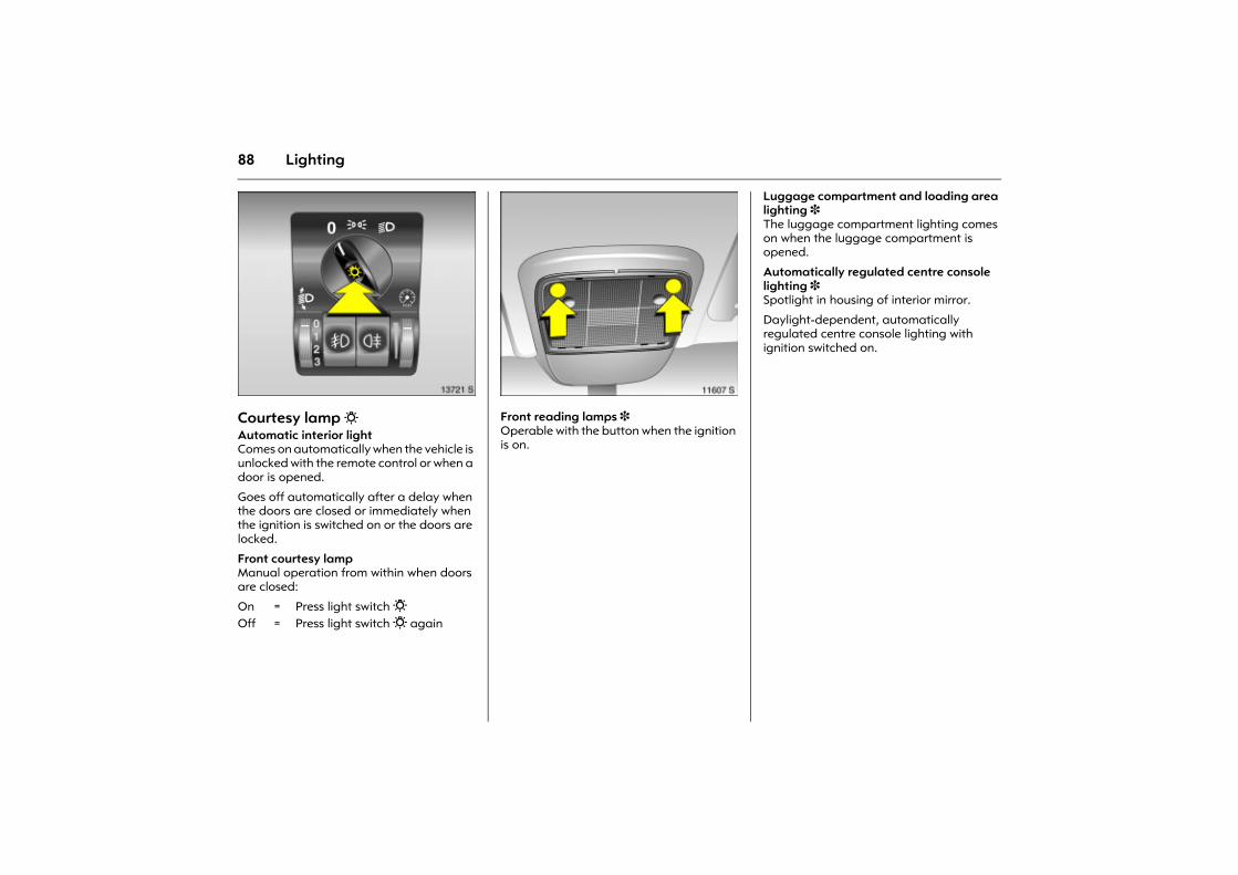
88 Lighting
Picture no: 13721s.tifCourtesy lamp 0Automatic interior light Comes on automatically when the vehicle is unlocked with the remote control or when a door is opened.
Goes off automatically after a delay when the doors are closed or immediately when the ignition is switched on or the doors are locked.
Front courtesy lampManual operation from within when doors are closed:
Picture no: 11607s.tifFront reading lamps 3 Operable with the button when the ignition is on.
Luggage compartment and loading area lighting 3 The luggage compartment lighting comes on when the luggage compartment is opened.
Automatically regulated centre console lighting 3 Spotlight in housing of interior mirror.
Daylight-dependent, automatically regulated centre console lighting with ignition switched on.
On = Press light switch 0Off = Press light switch 0 again
89Lighting
Battery discharge protection 3 Some consumers such as the interior lighting switch themselves off after approx. 30 minutes if the ignition is off in order to protect the battery charge.
Misted light covers The inside of the lamp bezels may mist briefly when subjected to adverse wet and cold winter conditions, strong rain or after the vehicle is washed. The misting will clear up on its own after a brief period. This can be facilitated by switching on the lights.
Headlamps when driving abroad The asymmetrical dipped beam increases the field of vision on the passenger side of the lane.
This causes glare for oncoming traffic if the vehicle is driven in countries where traffic drives on the opposite side of the road.
To avoid glare, have headlamps adjusted in a workshop or have covers fitted to both headlamps.
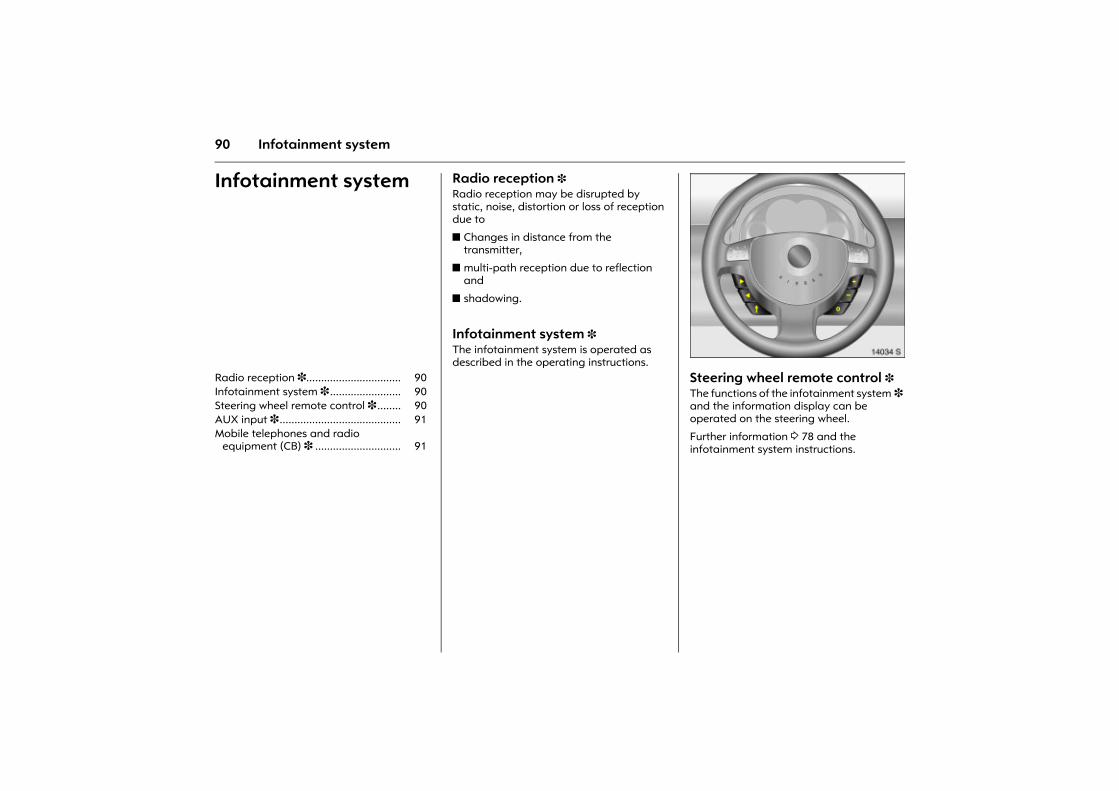
90 Infotainment system
Infotainment system Radio reception 3 Radio reception may be disrupted by static, noise, distortion or loss of reception due to
z Changes in distance from the transmitter,
z multi-path reception due to reflection and
z shadowing.
Infotainment system 3 The infotainment system is operated as described in the operating instructions. Picture no: 14034s.tif
Steering wheel remote control 3 The functions of the infotainment system 3 and the information display can be operated on the steering wheel.
Further information 3 78 and the infotainment system instructions.
Radio reception 3................................ 90 Infotainment system 3 ........................ 90 Steering wheel remote control 3 ........ 90 AUX input 3 ......................................... 91 Mobile telephones and radio
equipment (CB) 3 ............................. 91
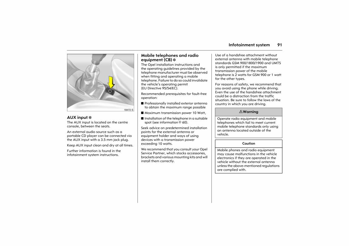
91Infotainment system
Picture no: 18472s.tifAUX input 3 The AUX input is located on the centre console, between the seats.
An external audio source such as a portable CD player can be connected via the AUX input with a 3.5 mm jack plug.
Keep AUX input clean and dry at all times.
Further information is found in the infotainment system instructions.
Mobile telephones and radio equipment (CB) 3 The Opel installation instructions and the operating guidelines provided by the telephone manufacturer must be observed when fitting and operating a mobile telephone. Failure to do so could invalidate the vehicle�s operating permit (EU Directive 95/54/EC).
Recommended prerequisites for fault-free operation:
z Professionally installed exterior antenna to obtain the maximum range possible
z Maximum transmission power 10 Watt,
z Installation of the telephone in a suitable spot (see information 3 60).
Seek advice on predetermined installation points for the external antenna or equipment holder and ways of using devices with a transmission power exceeding 10 watts.
We recommend that you consult your Opel Service Partner, which stocks accessories, brackets and various mounting kits and will install them correctly.
Use of a handsfree attachment without external antenna with mobile telephone standards GSM 900/1800/1900 and UMTS is only permitted if the maximum transmission power of the mobile telephone is 2 watts for GSM 900 or 1 watt for the other types.
For reasons of safety, we recommend that you avoid using the phone while driving. Even the use of the handsfree attachment could be a distraction from the traffic situation. Be sure to follow the laws of the country in which you are driving.
9 Warning
Operate radio equipment and mobile telephones which fail to meet current mobile telephone standards only using an antenna located outside of the vehicle.
Caution
Mobile phones and radio equipment may cause malfunctions in the vehicle electronics if they are operated in the vehicle without the external antenna unless the above-mentioned regulations are complied with.
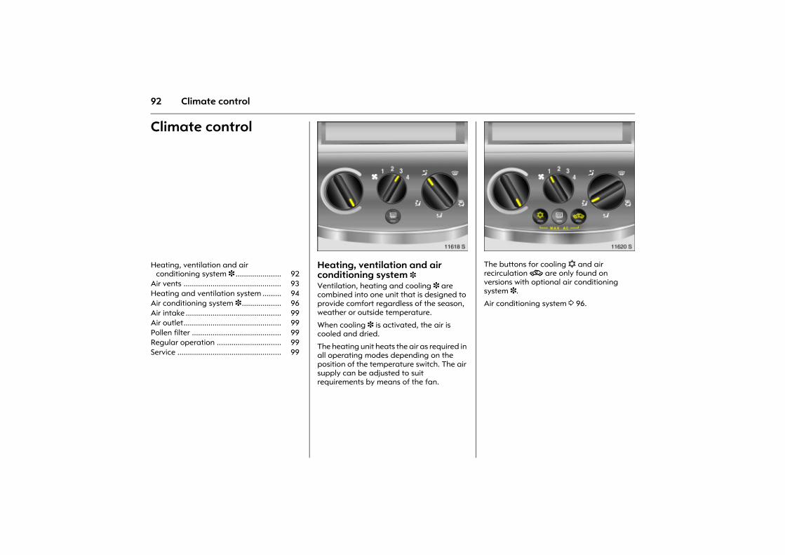
92 Climate control
Climate control
Picture no: 11618s.tifHeating, ventilation and air conditioning system 3 Ventilation, heating and cooling 3 are combined into one unit that is designed to provide comfort regardless of the season, weather or outside temperature.
When cooling 3 is activated, the air is cooled and dried.
The heating unit heats the air as required in all operating modes depending on the position of the temperature switch. The air supply can be adjusted to suit requirements by means of the fan.
Picture no: 11620s.tifThe buttons for cooling n and air recirculation 4 are only found on versions with optional air conditioning system 3.
Air conditioning system 3 96.
Heating, ventilation and air conditioning system 3 ...................... 92
Air vents ............................................... 93 Heating and ventilation system ......... 94 Air conditioning system 3................... 96 Air intake .............................................. 99 Air outlet............................................... 99 Pollen filter ........................................... 99 Regular operation ............................... 99 Service .................................................. 99
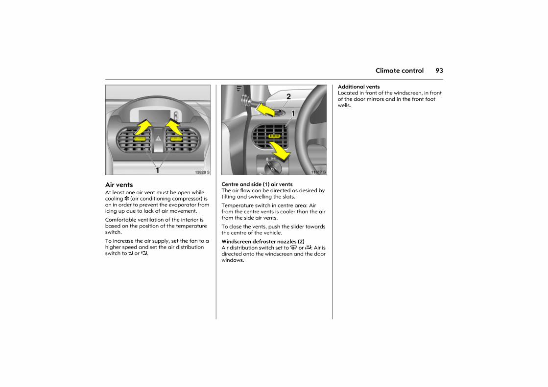
93Climate control
Picture no: 15928s.tifAir vents At least one air vent must be open while cooling 3 (air conditioning compressor) is on in order to prevent the evaporator from icing up due to lack of air movement.
Comfortable ventilation of the interior is based on the position of the temperature switch.
To increase the air supply, set the fan to a higher speed and set the air distribution switch to M or L.
Picture no: 11617s.tifCentre and side (1) air vents The air flow can be directed as desired by tilting and swivelling the slats.
Temperature switch in centre area: Air from the centre vents is cooler than the air from the side air vents.
To close the vents, push the slider towards the centre of the vehicle.
Windscreen defroster nozzles (2) Air distribution switch set to V or J: Air is directed onto the windscreen and the door windows.
Additional vents Located in front of the windscreen, in front of the door mirrors and in the front foot wells.
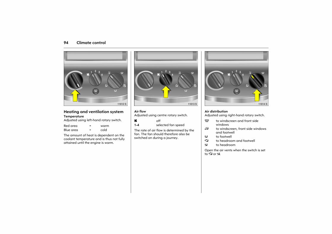
94 Climate control
Picture no: 11612s.tifHeating and ventilation systemTemperature Adjusted using left-hand rotary switch.
The amount of heat is dependent on the coolant temperature and is thus not fully attained until the engine is warm.
Picture no: 11613s.tifAir flow Adjusted using centre rotary switch.
The rate of air flow is determined by the fan. The fan should therefore also be switched on during a journey.
Picture no: 11614s.tifAir distribution Adjusted using right-hand rotary switch.
Open the air vents when the switch is set to L or M.
Red area = warmBlue area = cold
x off1-4 selected fan speed
V to windscreen and front side windows
J to windscreen, front side windows and footwell
K to footwellL to headroom and footwellM to headroom
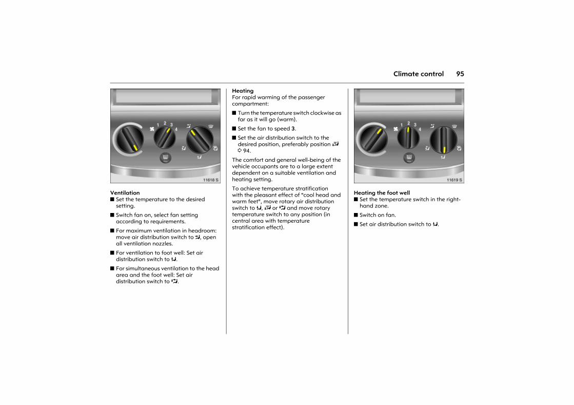
95Climate control
Picture no: 11618s.tifVentilation z Set the temperature to the desired
setting.
z Switch fan on, select fan setting according to requirements.
z For maximum ventilation in headroom: move air distribution switch to M, open all ventilation nozzles.
z For ventilation to foot well: Set air distribution switch to K.
z For simultaneous ventilation to the head area and the foot well: Set air distribution switch to L.
Heating For rapid warming of the passenger compartment:
z Turn the temperature switch clockwise as far as it will go (warm).
z Set the fan to speed 3.
z Set the air distribution switch to the desired position, preferably position J 3 94.
The comfort and general well-being of the vehicle occupants are to a large extent dependent on a suitable ventilation and heating setting.
To achieve temperature stratification with the pleasant effect of "cool head and warm feet", move rotary air distribution switch to K, J or L and move rotary temperature switch to any position (in central area with temperature stratification effect).
Picture no: 11619s.tifHeating the foot well z Set the temperature switch in the right-
hand zone.
z Switch on fan.
z Set air distribution switch to K.
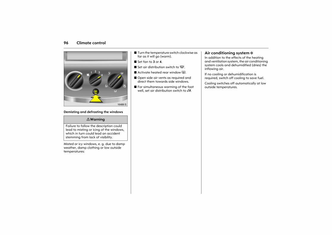
96 Climate control
Picture no: 16489s.tifDemisting and defrosting the windows
Misted or icy windows, e. g. due to damp weather, damp clothing or low outside temperatures:
z Turn the temperature switch clockwise as far as it will go (warm).
z Set fan to 3 or 4.
z Set air distribution switch to V.
z Activate heated rear window Ü.
z Open side air vents as required and direct them towards side windows.
z For simultaneous warming of the foot well, set air distribution switch to J.
Air conditioning system 3In addition to the effects of the heating and ventilation system, the air conditioning system cools and dehumidified (dries) the inflowing air.
If no cooling or dehumidification is required, switch off cooling to save fuel.
Cooling switches off automatically at low outside temperatures.
9 Warning
Failure to follow the description could lead to misting or icing of the windows, which in turn could lead an accident stemming from lack of visibility.
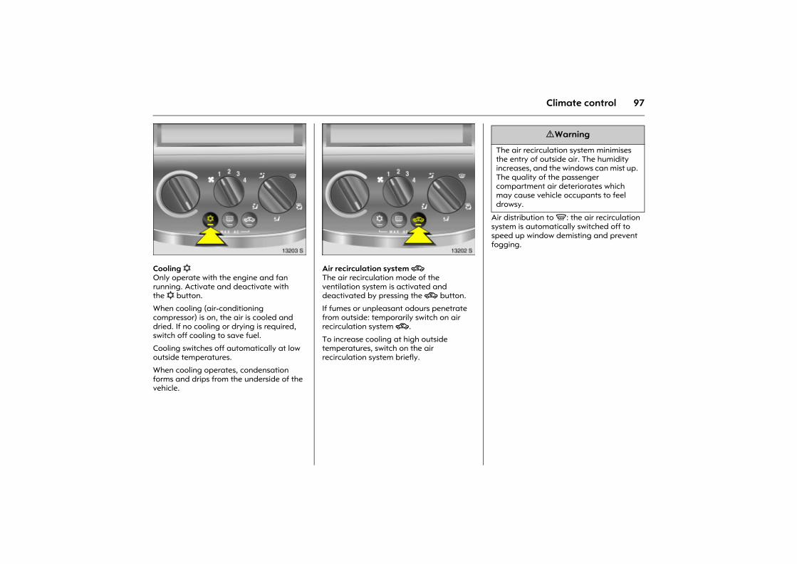
97Climate control
Picture no: 13203s.tifCooling n Only operate with the engine and fan running. Activate and deactivate with the n button.
When cooling (air-conditioning compressor) is on, the air is cooled and dried. If no cooling or drying is required, switch off cooling to save fuel.
Cooling switches off automatically at low outside temperatures.
When cooling operates, condensation forms and drips from the underside of the vehicle.
Picture no: 13202s.tifAir recirculation system 4 The air recirculation mode of the ventilation system is activated and deactivated by pressing the 4 button.
If fumes or unpleasant odours penetrate from outside: temporarily switch on air recirculation system 4.
To increase cooling at high outside temperatures, switch on the air recirculation system briefly.
Air distribution to V: the air recirculation system is automatically switched off to speed up window demisting and prevent fogging.
9 Warning
The air recirculation system minimises the entry of outside air. The humidity increases, and the windows can mist up. The quality of the passenger compartment air deteriorates which may cause vehicle occupants to feel drowsy.
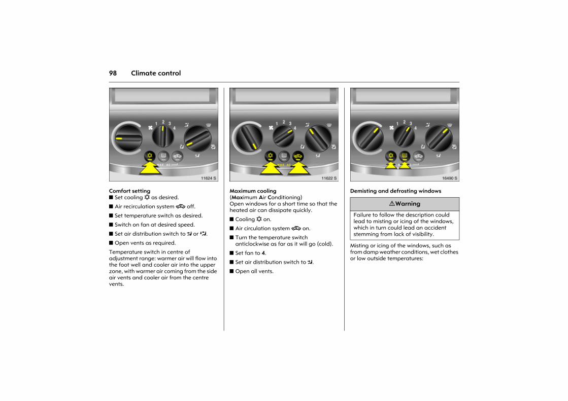
98 Climate control
Picture no: 11624s.tifComfort setting z Set cooling n as desired.
z Air recirculation system 4 off.
z Set temperature switch as desired.
z Switch on fan at desired speed.
z Set air distribution switch to M or L.
z Open vents as required.
Temperature switch in centre of adjustment range: warmer air will flow into the foot well and cooler air into the upper zone, with warmer air coming from the side air vents and cooler air from the centre vents.
Picture no: 11622s.tifMaximum cooling (Maximum Air Conditioning) Open windows for a short time so that the heated air can dissipate quickly.
z Cooling n on.
z Air circulation system 4 on.
z Turn the temperature switch anticlockwise as far as it will go (cold).
z Set fan to 4.
z Set air distribution switch to M.
z Open all vents.
Picture no: 16490s.tifDemisting and defrosting windows
Misting or icing of the windows, such as from damp weather conditions, wet clothes or low outside temperatures:
9 Warning
Failure to follow the description could lead to misting or icing of the windows, which in turn could lead an accident stemming from lack of visibility.
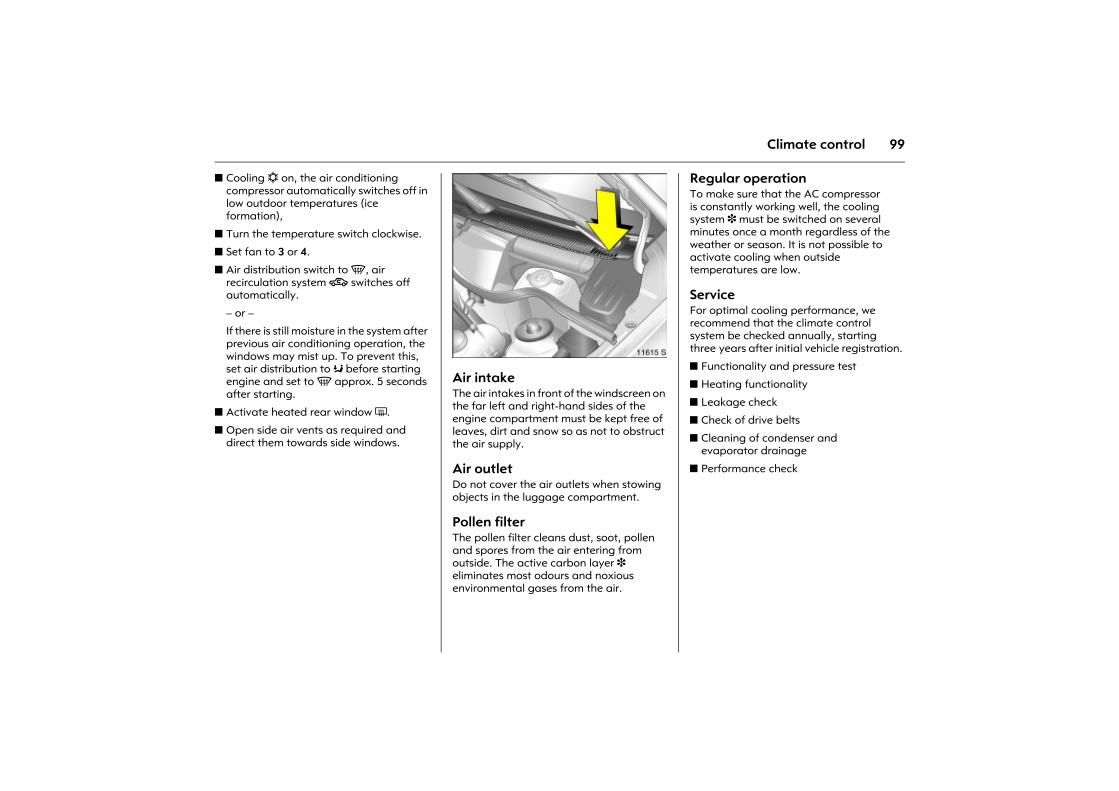
99Climate control
z Cooling n on, the air conditioning compressor automatically switches off in low outdoor temperatures (ice formation),
z Turn the temperature switch clockwise.
z Set fan to 3 or 4.
z Air distribution switch to V, air recirculation system 4 switches off automatically.
� or �
If there is still moisture in the system after previous air conditioning operation, the windows may mist up. To prevent this, set air distribution to K before starting engine and set to V approx. 5 seconds after starting.
z Activate heated rear window Ü.
z Open side air vents as required and direct them towards side windows.
Picture no: 11615s.tifAir intake The air intakes in front of the windscreen on the far left and right-hand sides of the engine compartment must be kept free of leaves, dirt and snow so as not to obstruct the air supply.
Air outletDo not cover the air outlets when stowing objects in the luggage compartment.
Pollen filter The pollen filter cleans dust, soot, pollen and spores from the air entering from outside. The active carbon layer 3 eliminates most odours and noxious environmental gases from the air.
Regular operationTo make sure that the AC compressor is constantly working well, the cooling system 3 must be switched on several minutes once a month regardless of the weather or season. It is not possible to activate cooling when outside temperatures are low.
Service For optimal cooling performance, we recommend that the climate control system be checked annually, starting three years after initial vehicle registration.
z Functionality and pressure test
z Heating functionality
z Leakage check
z Check of drive belts
z Cleaning of condenser and evaporator drainage
z Performance check
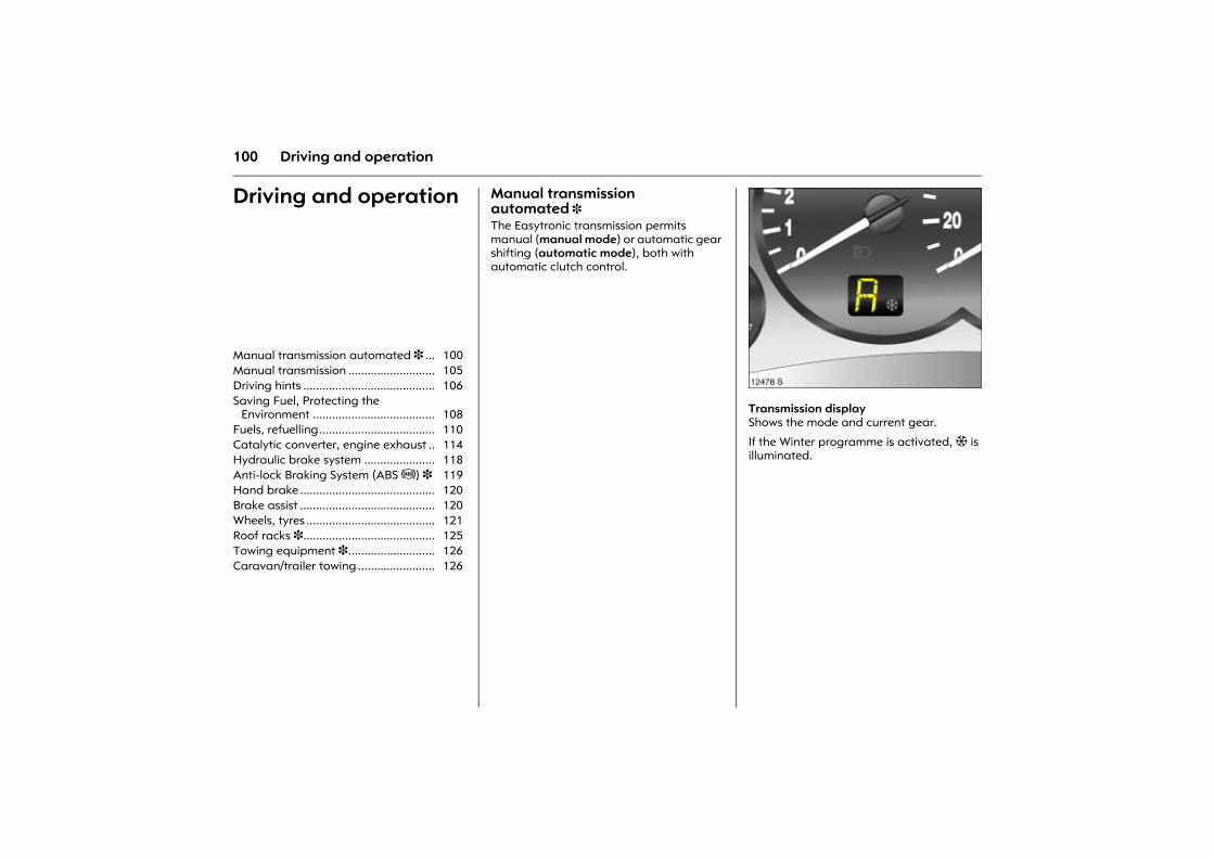
100 Driving and operation
Driving and operation Manual transmission automated 3 The Easytronic transmission permits manual (manual mode) or automatic gear shifting (automatic mode), both with automatic clutch control.
Picture no: 12478s.tifTransmission display Shows the mode and current gear.
If the Winter programme is activated, T is illuminated.
Manual transmission automated 3 ... 100 Manual transmission ........................... 105 Driving hints ......................................... 106 Saving Fuel, Protecting the
Environment ...................................... 108 Fuels, refuelling.................................... 110 Catalytic converter, engine exhaust .. 114 Hydraulic brake system ...................... 118 Anti-lock Braking System (ABS u) 3 119 Hand brake .......................................... 120 Brake assist .......................................... 120 Wheels, tyres ........................................ 121 Roof racks 3......................................... 125 Towing equipment 3........................... 126 Caravan/trailer towing ........................ 126
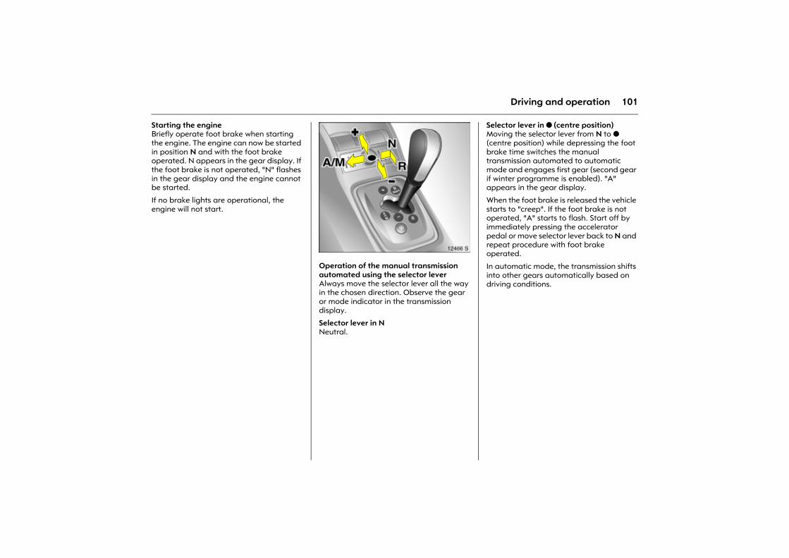
101Driving and operation
Starting the engineBriefly operate foot brake when starting the engine. The engine can now be started in position N and with the foot brake operated. N appears in the gear display. If the foot brake is not operated, "N" flashes in the gear display and the engine cannot be started.
If no brake lights are operational, the engine will not start.
Picture no: 12466s.tifOperation of the manual transmission automated using the selector lever Always move the selector lever all the way in the chosen direction. Observe the gear or mode indicator in the transmission display.
Selector lever in N Neutral.
Selector lever in o (centre position) Moving the selector lever from N to o (centre position) while depressing the foot brake time switches the manual transmission automated to automatic mode and engages first gear (second gear if winter programme is enabled). "A" appears in the gear display.
When the foot brake is released the vehicle starts to "creep". If the foot brake is not operated, "A" starts to flash. Start off by immediately pressing the accelerator pedal or move selector lever back to N and repeat procedure with foot brake operated.
In automatic mode, the transmission shifts into other gears automatically based on driving conditions.
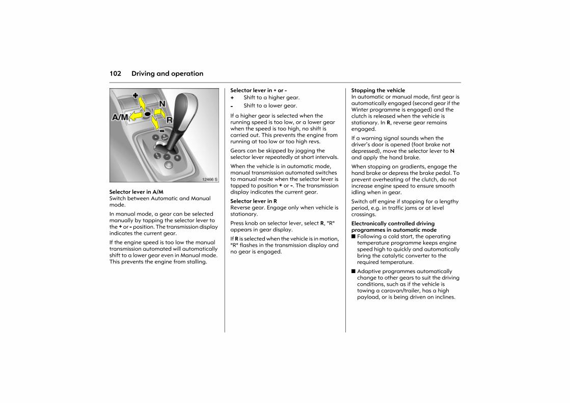
102 Driving and operation
Picture no: 12466s.tifSelector lever in A/MSwitch between Automatic and Manual mode.
In manual mode, a gear can be selected manually by tapping the selector lever to the + or - position. The transmission display indicates the current gear.
If the engine speed is too low the manual transmission automated will automatically shift to a lower gear even in Manual mode. This prevents the engine from stalling.
Selector lever in + or -
If a higher gear is selected when the running speed is too low, or a lower gear when the speed is too high, no shift is carried out. This prevents the engine from running at too low or too high revs.
Gears can be skipped by jogging the selector lever repeatedly at short intervals.
When the vehicle is in automatic mode, manual transmission automated switches to manual mode when the selector lever is tapped to position + or -. The transmission display indicates the current gear.
Selector lever in RReverse gear. Engage only when vehicle is stationary.
Press knob on selector lever, select R, "R" appears in gear display.
If R is selected when the vehicle is in motion, "R" flashes in the transmission display and no gear is engaged.
Stopping the vehicle In automatic or manual mode, first gear is automatically engaged (second gear if the Winter programme is engaged) and the clutch is released when the vehicle is stationary. In R, reverse gear remains engaged.
If a warning signal sounds when the driver�s door is opened (foot brake not depressed), move the selector lever to N and apply the hand brake.
When stopping on gradients, engage the hand brake or depress the brake pedal. To prevent overheating of the clutch, do not increase engine speed to ensure smooth idling when in gear.
Switch off engine if stopping for a lengthy period, e.g. in traffic jams or at level crossings.
Electronically controlled driving programmes in automatic mode z Following a cold start, the operating
temperature programme keeps engine speed high to quickly and automatically bring the catalytic converter to the required temperature.
z Adaptive programmes automatically change to other gears to suit the driving conditions, such as if the vehicle is towing a caravan/trailer, has a high payload, or is being driven on inclines.
+ Shift to a higher gear.
- Shift to a lower gear.
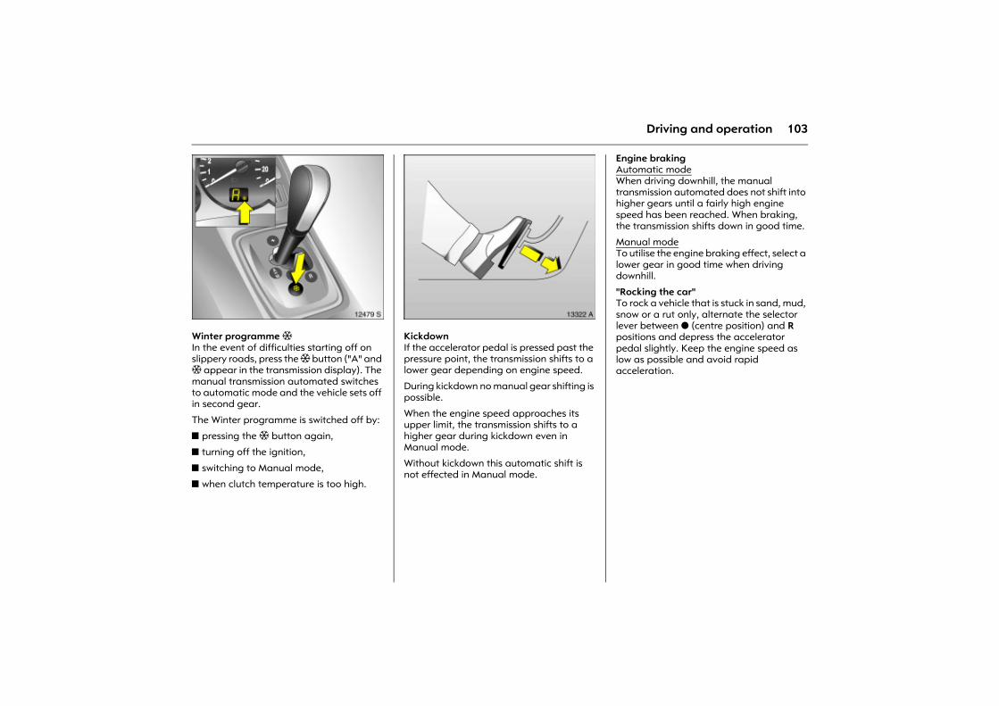
103Driving and operation
Picture no: 12479S.tifWinter programme T In the event of difficulties starting off on slippery roads, press the T button ("A" and T appear in the transmission display). The manual transmission automated switches to automatic mode and the vehicle sets off in second gear.
The Winter programme is switched off by:
z pressing the T button again,
z turning off the ignition,
z switching to Manual mode,
z when clutch temperature is too high.
Picture no: 13322a.tifKickdown If the accelerator pedal is pressed past the pressure point, the transmission shifts to a lower gear depending on engine speed.
During kickdown no manual gear shifting is possible.
When the engine speed approaches its upper limit, the transmission shifts to a higher gear during kickdown even in Manual mode.
Without kickdown this automatic shift is not effected in Manual mode.
Engine braking Automatic modeWhen driving downhill, the manual transmission automated does not shift into higher gears until a fairly high engine speed has been reached. When braking, the transmission shifts down in good time.
Manual modeTo utilise the engine braking effect, select a lower gear in good time when driving downhill.
"Rocking the car" To rock a vehicle that is stuck in sand, mud, snow or a rut only, alternate the selector lever between o (centre position) and R positions and depress the accelerator pedal slightly. Keep the engine speed as low as possible and avoid rapid acceleration.
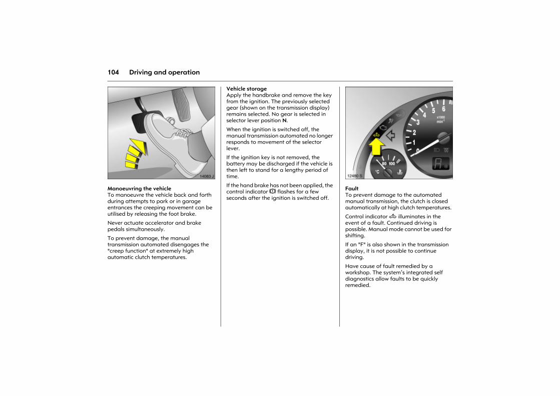
104 Driving and operation
Picture no: 14083j.tifManoeuvring the vehicle To manoeuvre the vehicle back and forth during attempts to park or in garage entrances the creeping movement can be utilised by releasing the foot brake.
Never actuate accelerator and brake pedals simultaneously.
To prevent damage, the manual transmission automated disengages the "creep function" at extremely high automatic clutch temperatures.
Vehicle storageApply the handbrake and remove the key from the ignition. The previously selected gear (shown on the transmission display) remains selected. No gear is selected in selector lever position N.
When the ignition is switched off, the manual transmission automated no longer responds to movement of the selector lever.
If the ignition key is not removed, the battery may be discharged if the vehicle is then left to stand for a lengthy period of time.
If the hand brake has not been applied, the control indicator R flashes for a few seconds after the ignition is switched off.
Picture no: 12480s.tifFault To prevent damage to the automated manual transmission, the clutch is closed automatically at high clutch temperatures.
Control indicator A illuminates in the event of a fault. Continued driving is possible. Manual mode cannot be used for shifting.
If an "F" is also shown in the transmission display, it is not possible to continue driving.
Have cause of fault remedied by a workshop. The system�s integrated self diagnostics allow faults to be quickly remedied.
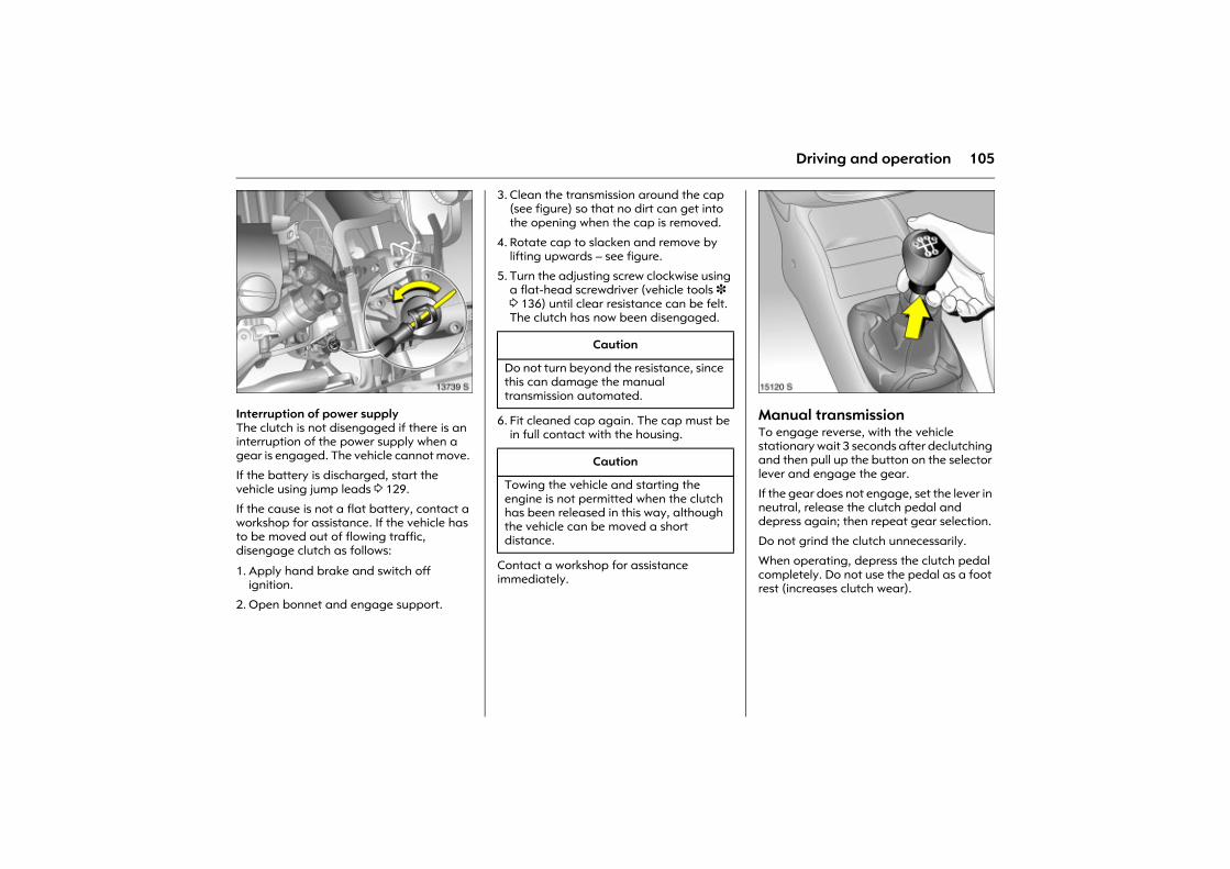
105Driving and operation
Picture no: 13739s.tifInterruption of power supply The clutch is not disengaged if there is an interruption of the power supply when a gear is engaged. The vehicle cannot move.
If the battery is discharged, start the vehicle using jump leads 3 129.
If the cause is not a flat battery, contact a workshop for assistance. If the vehicle has to be moved out of flowing traffic, disengage clutch as follows:
1. Apply hand brake and switch off ignition.
2. Open bonnet and engage support.
3. Clean the transmission around the cap (see figure) so that no dirt can get into the opening when the cap is removed.
4. Rotate cap to slacken and remove by lifting upwards � see figure.
5. Turn the adjusting screw clockwise using a flat-head screwdriver (vehicle tools 3 3 136) until clear resistance can be felt. The clutch has now been disengaged.
6. Fit cleaned cap again. The cap must be in full contact with the housing.
Contact a workshop for assistance immediately.
Picture no: 15120s.tifManual transmissionTo engage reverse, with the vehicle stationary wait 3 seconds after declutching and then pull up the button on the selector lever and engage the gear.
If the gear does not engage, set the lever in neutral, release the clutch pedal and depress again; then repeat gear selection.
Do not grind the clutch unnecessarily.
When operating, depress the clutch pedal completely. Do not use the pedal as a foot rest (increases clutch wear).
Caution
Do not turn beyond the resistance, since this can damage the manual transmission automated.
Caution
Towing the vehicle and starting the engine is not permitted when the clutch has been released in this way, although the vehicle can be moved a short distance.

106 Driving and operation
Driving hints The first 1000 km Drive your vehicle at various speeds. Do not use full throttle. Never allow the engine to labour at low revs.
Change gear frequently. Do not press the accelerator pedal more than approx. 3/4 in all gears.
Do not drive faster than three quarters of maximum speed.
Do not brake unnecessarily hard for the first 200 km.
During the first drive, smoke may develop because of wax and oil evaporating off the exhaust system. Park the vehicle in the open for a while after the first drive and avoid inhaling the fumes.
Fuel and engine oil consumption is higher than normal during the running-in period.
Never coast with engine not running Many units will not function in this situation (e.g. brake servo unit, power steering 3). Driving in this manner is a danger to yourself and others.
Brake servo unit When the engine is not running, the brake servo unit is no longer effective once the brake pedal has been depressed once or twice. Braking effect is not reduced, but significantly greater force is required for braking.
Electric power steering 3 If the power-assisted steering fails when being towed with the engine switched off � the vehicle can still be steered, but considerably more force is required.
Driving in mountainous terrain or with a trailer/caravan The cooling fan is electrically operated. Its cooling power is therefore independent of the engine speed.
Since a considerable amount of heat is generated at high engine speeds and less at slower speeds, do not shift down when climbing hills whilst the vehicle is still coping with the gradient in the higher gear.
Diesel engines: On gradients of 10 % or more, do not drive faster than 30 km/h in first gear or 50 km/h in second gear.
Driving with a roof load Do not exceed the permissible roof load, 3 189. For reasons of safety, distribute the load evenly and strap it down firmly using retaining straps so that it cannot slip. Check the tyre pressure when the vehicle is loaded. Do not travel faster than 120 km/h. Check and re-tighten the straps frequently. Observe country-specific regulations.
Switching off the engine When you switch off, fans in the engine compartment may continue running for a time to cool the engine.
If the engine temperature is very high, e.g. after driving in mountainous terrain: allow the engine to idle for approximately two minutes in order to prevent heat accumulation.
Vehicles with turbocharged engine After running at high engine speeds or high engine loads, operate the engine briefly at a low load or run in neutral for approx. 30 seconds before switching off in order to protect the turbocharger.
107Driving and operation
Save energy � more kilometres Please observe the running-in hints on the previous page and the tips for saving energy on the following pages.
Good, technically correct and economical driving ensures maximum durability and performance for your vehicle.
Overrun cut-off The fuel supply is automatically cut off during overrun, e.g. when the vehicle is driven with a gear engaged but no throttle application. Overrun cut-off is deactivated if catalytic converter temperature is high.
Vehicles with turbocharged engine Flow-generated noises may be audible if the accelerator is released quickly on account of air flow in the turbocharger.
Engine speed Drive in a low engine speed range for each gear as much as possible.
Warming up Allow the engine to warm up while driving. Do not warm it up by letting it run at idling speed. Do not apply full throttle until the engine has reached operating temperature.
In automatic mode, the manual transmission automated 3 does not shift to the higher gears after a cold start until higher engine speeds are reached. This allows the catalytic converter to quickly reach the temperature that is required for optimum pollutant reduction.
Correct gear selection Do not race your engine whilst in neutral or with a low gear selected. Driving too fast in individual gears as well as stop-and-go traffic increases engine wear and fuel consumption.
Change down When decreasing speed, shift down into the next lowest gear. Do not slip the clutch with a high-revving engine. This is especially important when hill climbing.
Cooling fan The cooling fan is controlled via a thermoswitch and therefore only runs if necessary.
The cooling fan automatically switches on when the diesel particle filter is being cleaned 3 depending on the engine.
Pedals Do not place any objects in the foot well which could slip under the pedals and inhibit the pedal travel.
To ensure the pedal travel is uninhibited, there must be no mats in the area of the pedals.
Battery care When driving slowly or when the vehicle is stationary, e.g. in slow urban traffic, stop-and-go traffic or traffic jams, turn off all unnecessary electrical loads where possible (e.g. heated rear window, heated front seats, etc.).
Declutch when starting in order to relieve the strain on the starter and the battery.
108 Driving and operation
Saving Fuel, Protecting the Environment Trend-setting technologyEnvironmentally friendly and mainly recyclable materials were used when your vehicle was being developed and manufactured. The production methods used to make your vehicle are also environmentally-compatible.
Recycling of production wastes keeps the circulation of material closed. Reduction of energy and water requirements also helps to conserve natural resources.
A highly advanced design means that your vehicle can be easily disassembled at the end of its working life, and the individual materials separated for subsequent re-use.
Materials such as asbestos and cadmium are not used. The refrigerant in the air conditioning system 3 is CFC-free.
New painting techniques employ water as a solvent.
End-of-life vehicle recovery Information on end-of-life vehicle recovery centres and the recycling of end-of-life vehicles is available at www.opel.com.
Energy and environment-conscious driving z High noise levels and exhaust emissions
are often a result of driving without due attention to saving energy and protecting the environment.
z You should therefore drive with energy in mind: "more kilometres � less fuel".
Reduce the noise level and exhaust emissions by adopting an environment-conscious driving style. This is extremely worthwhile and improves the quality of life.
Fuel consumption depends to a great extent on your own personal driving style. The following hints are intended to help you consume fuel at a rate that is as close as possible to the specified levels 3 186.
Check your vehicle�s fuel consumption every time you refuel. This facilitates early detection of any irregularities causing increased fuel consumption.
Warming up z Full throttle and warming up at idle
speed increase wear, fuel consumption, exhaust emission, the amount of pollutant in the exhaust and the amount of noise.
z Drive off immediately after starting. Warm up the engine by running it at moderate engine speeds.
Uniform speed z Hectic driving significantly increases fuel
consumption, the exhaust emissions, the proportion of pollutant in the exhaust gas and the noise level.
z Do not accelerate and brake unnecessarily. Drive at uniform speed, watching the road.
Avoid frequent starting off and stopping e.g. at traffic lights, in short distance traffic and in queues of traffic by means of clever planning. Select roads with good traffic flow.
Idling z The engine also consumes fuel when
idling.
z If you have to wait for more than one minute, it is worthwhile switching off the engine. Five minutes of idling corresponds to approximately one kilometre of driving.
109Driving and operation
Overrun z The fuel supply is automatically shut off
during overrun, e.g. when the vehicle is being driven down long gradients or when braking 3 107.
z To enable the overrun cut-off to come into action and save fuel, do not accelerate or declutch during overrun.
Correct gear selection z High revs increase engine wear and fuel
consumption.
z Do not race your engine. Avoid driving at high engine speeds.
Making use of the tachometer helps to save fuel. Drive in a low engine speed range for each gear as much as possible with uniform engine speeds. Drive as often as possible in top gear, select the next higher gear as soon as possible, and only change down when the engine is no longer running perfectly smoothly.
High speed z The higher the speed, the higher the
consumption and the noise level. At top speed, you consume a great deal of fuel and produce excessive noise and exhaust emissions.
z Slightly releasing the accelerator pedal results in distinct fuel savings with no major loss of speed.
Drive at no more than around three quarters of maximum speed and you will use up to 50 % less fuel, without losing a great deal of time.
Tyre pressure z Inadequate tyre pressure, leading to
higher road resistance, costs money in two ways: for more fuel and increased tyre wear.
z Regular checks (every 14 days) pay off.
Electrical loadsz The power consumption of electrical
equipment increases fuel consumption.
z Switch off all auxiliary electrical loads (e.g. air conditioning 3, heated rear window) when not needed.
Roof racks z Due to air resistance, a roof load can
increase fuel consumption by approx. 1 l/100 km.
z Remove them if they are not being used.
Repair and maintenance z Improper repairs or adjustment and
maintenance work can increase fuel consumption. Do not carry out work on the engine yourself.
You may out of ignorance infringe environmental laws by not disposing of materials properly.
Appropriate parts might not be recycled.
Contact with some of the materials involved may pose a health hazard.
z We recommend that repair and maintenance be entrusted to your Opel Partner.
Extreme driving conditionsz Going up steep slopes, cornering, driving
on poor roads and winter driving all increase fuel consumption.
Fuel consumption increases dramatically in urban traffic and at winter temperatures, especially on short trips when the engine operating temperature is not reached.
z Following the instructions given above will minimise consumption under these conditions.
110 Driving and operation
Fuels, refuellingFuel consumption Fuel consumption is determined under specific driving conditions 3 186.
Special equipment increases the weight of the vehicle. As a result, they can increase fuel consumption and reduce the specified maximum speed.
There is increased friction between engine and transmission parts during the first 1000 kilometres. This increases fuel consumption.
Fuel for petrol engines Only use unleaded fuel that complies with DIN EN 228.
Fuels with ethanol content greater than 5 % may only be used if the vehicle has been specifically developed and approved for these fuels.
Use fuel with the recommended octane rating (value in bold 3 184). Use of fuel with too low an octane rating can reduce engine power and torque and slightly increases fuel consumption.
Fuel for diesel engines Only use diesel fuel that complies with DIN EN 590. The fuel must have low sulphur content (max. 50 ppm).
Do not use marine diesel oils, heating oils or entirely or partially plant-based diesel fuels, such as rape seed oil or bio diesel, Aquazole and similar diesel-water emulsions. Diesel fuels must not be diluted with fuels for petrol engines.
The flow and filterability of diesel fuel are temperature-dependent. When temperatures are low, refuel with diesel fuel with guaranteed winter properties.
Fuel for natural gas operation Use natural gas with a methane content of approx. 78-99 %. L-gas (low) has approx. 78-87 % and H-gas (high) has approx. 87-99 %. Biogas with the same methane content can also be used if it has been chemically prepared and desulphurised.
Liquid gas or LPG must not be used.
Caution
Use of fuel with too low an octane rating could lead to uncontrolled combustion and engine damage.
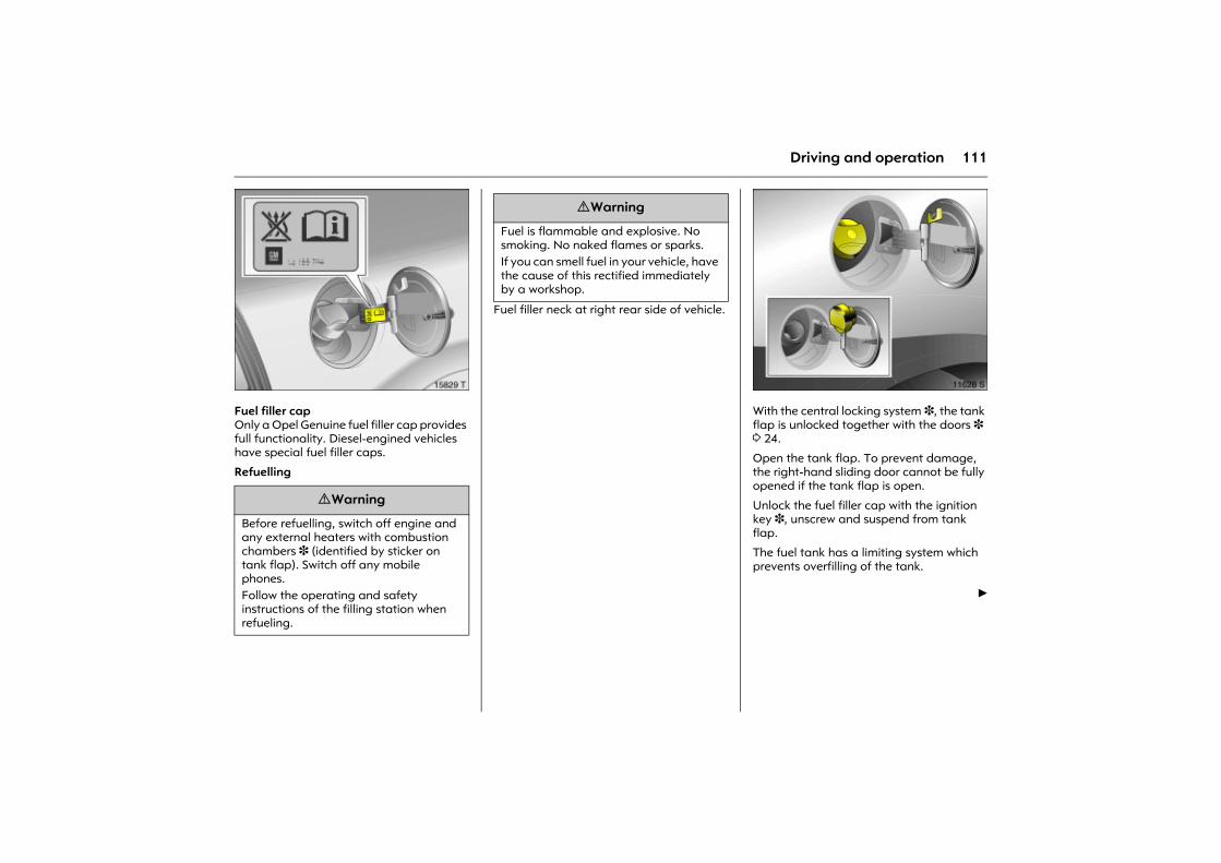
111Driving and operation
Picture no: 15829t.tifFuel filler cap Only a Opel Genuine fuel filler cap provides full functionality. Diesel-engined vehicles have special fuel filler caps.
Refuelling
Fuel filler neck at right rear side of vehicle.
Picture no: 11628s.tifWith the central locking system 3, the tank flap is unlocked together with the doors 3 3 24.
Open the tank flap. To prevent damage, the right-hand sliding door cannot be fully opened if the tank flap is open.
Unlock the fuel filler cap with the ignition key 3, unscrew and suspend from tank flap.
The fuel tank has a limiting system which prevents overfilling of the tank.
6
9 Warning
Before refuelling, switch off engine and any external heaters with combustion chambers 3 (identified by sticker on tank flap). Switch off any mobile phones. Follow the operating and safety instructions of the filling station when refueling.
9 Warning
Fuel is flammable and explosive. No smoking. No naked flames or sparks. If you can smell fuel in your vehicle, have the cause of this rectified immediately by a workshop.
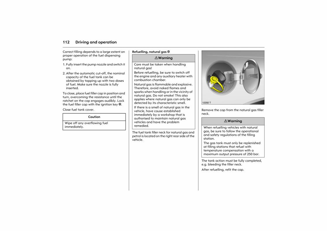
112 Driving and operation
Correct filling depends to a large extent on proper operation of the fuel dispensing pump:
1. Fully insert the pump nozzle and switch it on.
2. After the automatic cut-off, the nominal capacity of the fuel tank can be obtained by topping up with two doses of fuel. Make sure the nozzle is fully inserted.
To close, place fuel filler cap in position and turn, overcoming the resistance until the ratchet on the cap engages audibly. Lock the fuel filler cap with the ignition key 3.
Close fuel tank cover.
Refuelling, natural gas 3
The fuel tank filler neck for natural gas and petrol is located on the right rear side of the vehicle.
Picture no: 12292t.tifRemove the cap from the natural gas filler neck.
The tank action must be fully completed, e.g. bleeding the filler neck.
After refuelling, refit the cap.
Caution
Wipe off any overflowing fuel immediately.
9 Warning
Care must be taken when handling natural gas! Before refuelling, be sure to switch off the engine and any auxiliary heater with combustion chamber. Natural gas is flammable and explosive. Therefore, avoid naked flames and sparks when handling or in the vicinity of natural gas. Do not smoke! This also applies where natural gas can only be detected by its characteristic smell. If there is a smell of natural gas in the vehicle, have cause established immediately by a workshop that is authorised to maintain natural gas vehicles and have the problem remedied.
9 Warning
When refuelling vehicles with natural gas, be sure to follow the operational and safety regulations of the filling station.The gas tank must only be replenished at filling stations that refuel with temperature compensation with a maximum output pressure of 250 bar.
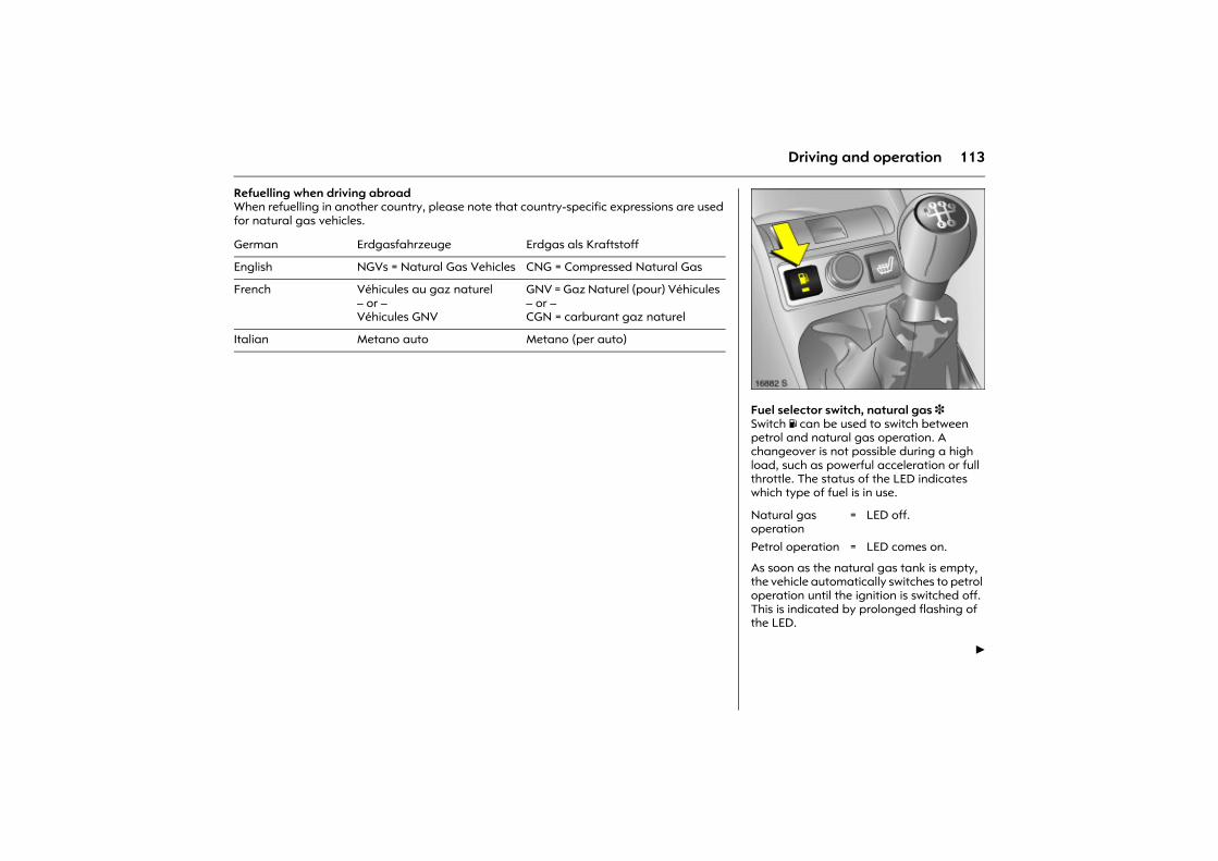
113Driving and operation
Refuelling when driving abroadWhen refuelling in another country, please note that country-specific expressions are used for natural gas vehicles.
German Erdgasfahrzeuge Erdgas als Kraftstoff
English NGVs = Natural Gas Vehicles CNG = Compressed Natural Gas
French Véhicules au gaz naturel� or �Véhicules GNV
GNV = Gaz Naturel (pour) Véhicules� or �CGN = carburant gaz naturel
Italian Metano auto Metano (per auto)
Picture no: 16882s.tifFuel selector switch, natural gas 3 Switch Y can be used to switch between petrol and natural gas operation. A changeover is not possible during a high load, such as powerful acceleration or full throttle. The status of the LED indicates which type of fuel is in use.
As soon as the natural gas tank is empty, the vehicle automatically switches to petrol operation until the ignition is switched off. This is indicated by prolonged flashing of the LED.
6
Natural gas operation
= LED off.
Petrol operation = LED comes on.
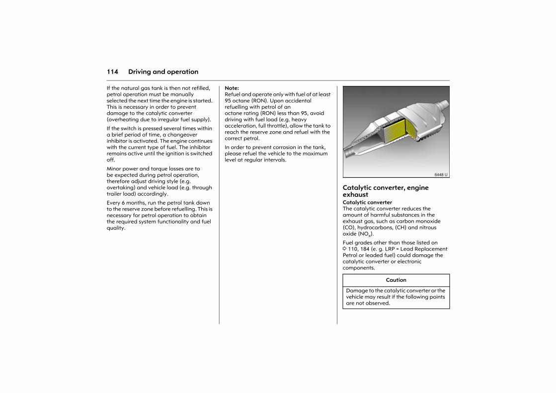
114 Driving and operation
If the natural gas tank is then not refilled, petrol operation must be manually selected the next time the engine is started. This is necessary in order to prevent damage to the catalytic converter (overheating due to irregular fuel supply).
If the switch is pressed several times within a brief period of time, a changeover inhibitor is activated. The engine continues with the current type of fuel. The inhibitor remains active until the ignition is switched off.
Minor power and torque losses are to be expected during petrol operation, therefore adjust driving style (e.g. overtaking) and vehicle load (e.g. through trailer load) accordingly.
Every 6 months, run the petrol tank down to the reserve zone before refuelling. This is necessary for petrol operation to obtain the required system functionality and fuel quality.
Note:Refuel and operate only with fuel of at least 95 octane (RON). Upon accidental refuelling with petrol of anoctane rating (RON) less than 95, avoid driving with fuel load (e.g. heavy acceleration, full throttle), allow the tank to reach the reserve zone and refuel with the correct petrol.
In order to prevent corrosion in the tank, please refuel the vehicle to the maximum level at regular intervals.
Picture no: 6448u.tifCatalytic converter, engine exhaust Catalytic converter The catalytic converter reduces the amount of harmful substances in the exhaust gas, such as carbon monoxide (CO), hydrocarbons, (CH) and nitrous oxide (NOx).
Fuel grades other than those listed on 3 110, 184 (e. g. LRP = Lead Replacement Petrol or leaded fuel) could damage the catalytic converter or electronic components.
Caution
Damage to the catalytic converter or the vehicle may result if the following points are not observed.
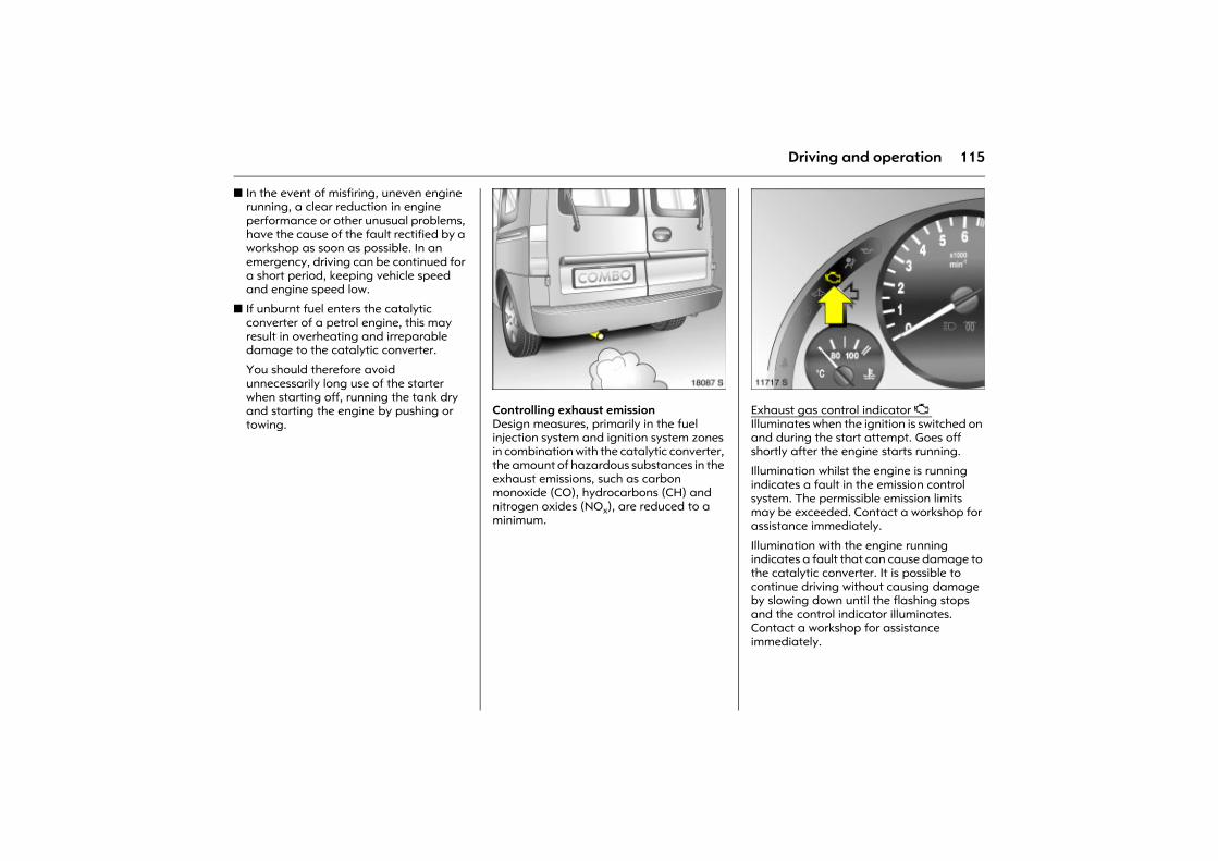
115Driving and operation
z In the event of misfiring, uneven engine running, a clear reduction in engine performance or other unusual problems, have the cause of the fault rectified by a workshop as soon as possible. In an emergency, driving can be continued for a short period, keeping vehicle speed and engine speed low.
z If unburnt fuel enters the catalytic converter of a petrol engine, this may result in overheating and irreparable damage to the catalytic converter.
You should therefore avoid unnecessarily long use of the starter when starting off, running the tank dry and starting the engine by pushing or towing.
Picture no: 18087s.tifControlling exhaust emission Design measures, primarily in the fuel injection system and ignition system zones in combination with the catalytic converter, the amount of hazardous substances in the exhaust emissions, such as carbon monoxide (CO), hydrocarbons (CH) and nitrogen oxides (NOx), are reduced to a minimum.
Picture no: 11717s.tifExhaust gas control indicator Z Illuminates when the ignition is switched on and during the start attempt. Goes off shortly after the engine starts running.
Illumination whilst the engine is running indicates a fault in the emission control system. The permissible emission limits may be exceeded. Contact a workshop for assistance immediately.
Illumination with the engine running indicates a fault that can cause damage to the catalytic converter. It is possible to continue driving without causing damage by slowing down until the flashing stops and the control indicator illuminates. Contact a workshop for assistance immediately.
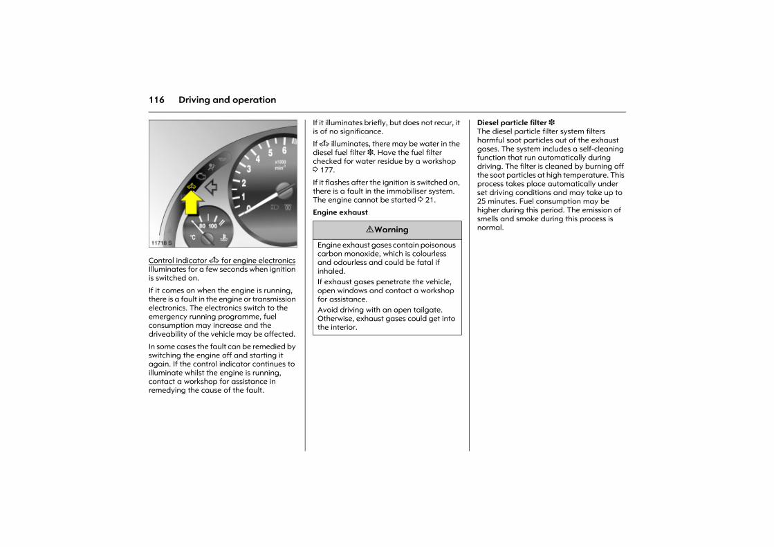
116 Driving and operation
Picture no: 11718s.tifControl indicator A for engine electronics Illuminates for a few seconds when ignition is switched on.
If it comes on when the engine is running, there is a fault in the engine or transmission electronics. The electronics switch to the emergency running programme, fuel consumption may increase and the driveability of the vehicle may be affected.
In some cases the fault can be remedied by switching the engine off and starting it again. If the control indicator continues to illuminate whilst the engine is running, contact a workshop for assistance in remedying the cause of the fault.
If it illuminates briefly, but does not recur, it is of no significance.
If A illuminates, there may be water in the diesel fuel filter 3. Have the fuel filter checked for water residue by a workshop 3 177.
If it flashes after the ignition is switched on, there is a fault in the immobiliser system. The engine cannot be started 3 21.
Engine exhaust
Diesel particle filter 3 The diesel particle filter system filters harmful soot particles out of the exhaust gases. The system includes a self-cleaning function that run automatically during driving. The filter is cleaned by burning off the soot particles at high temperature. This process takes place automatically under set driving conditions and may take up to 25 minutes. Fuel consumption may be higher during this period. The emission of smells and smoke during this process is normal. 9 Warning
Engine exhaust gases contain poisonous carbon monoxide, which is colourless and odourless and could be fatal if inhaled. If exhaust gases penetrate the vehicle, open windows and contact a workshop for assistance. Avoid driving with an open tailgate. Otherwise, exhaust gases could get into the interior.
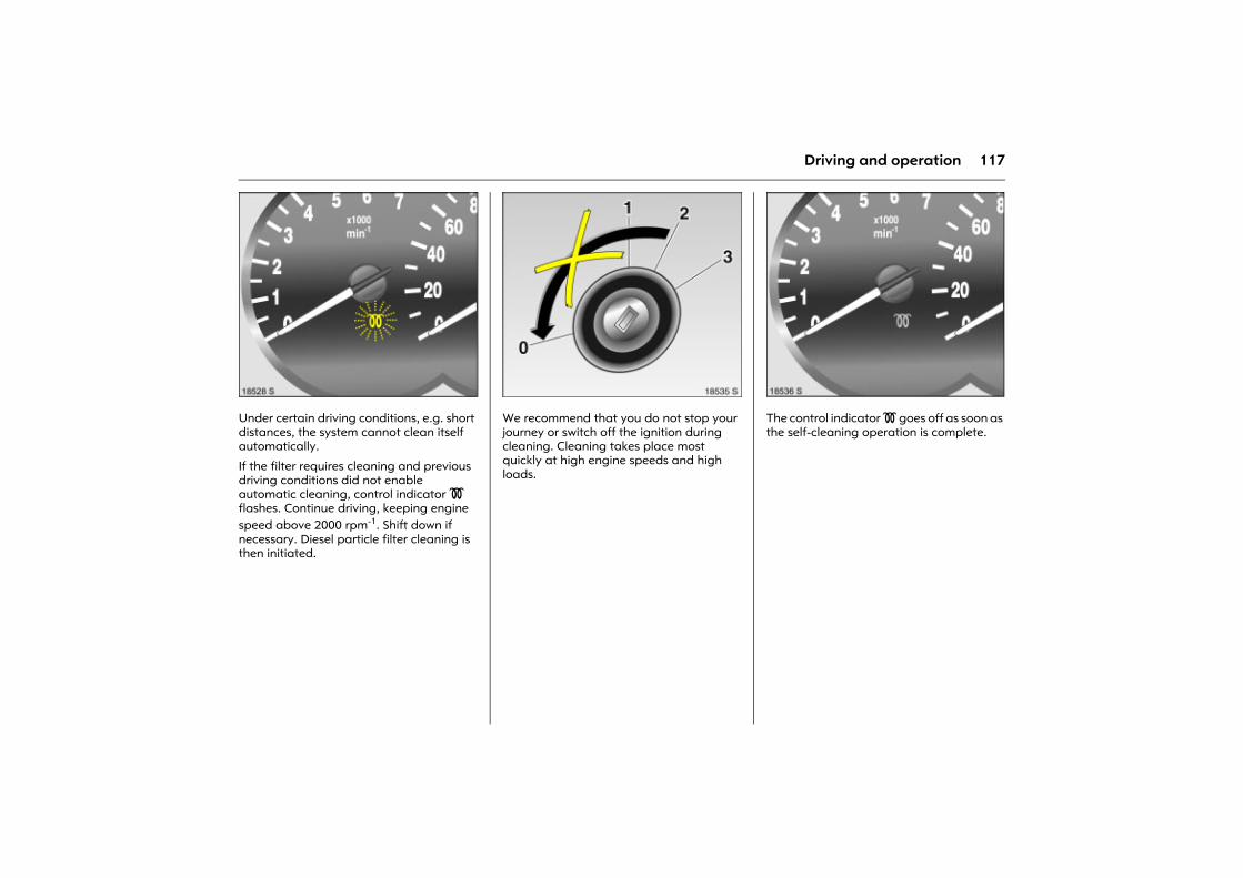
117Driving and operation
Picture no: 18528s.tifUnder certain driving conditions, e.g. short distances, the system cannot clean itself automatically.
If the filter requires cleaning and previous driving conditions did not enable automatic cleaning, control indicator ! flashes. Continue driving, keeping engine speed above 2000 rpm-1. Shift down if necessary. Diesel particle filter cleaning is then initiated.
Picture no: 18535s.tifWe recommend that you do not stop your journey or switch off the ignition during cleaning. Cleaning takes place most quickly at high engine speeds and high loads.
Picture no: 18536s.tifThe control indicator ! goes off as soon as the self-cleaning operation is complete.
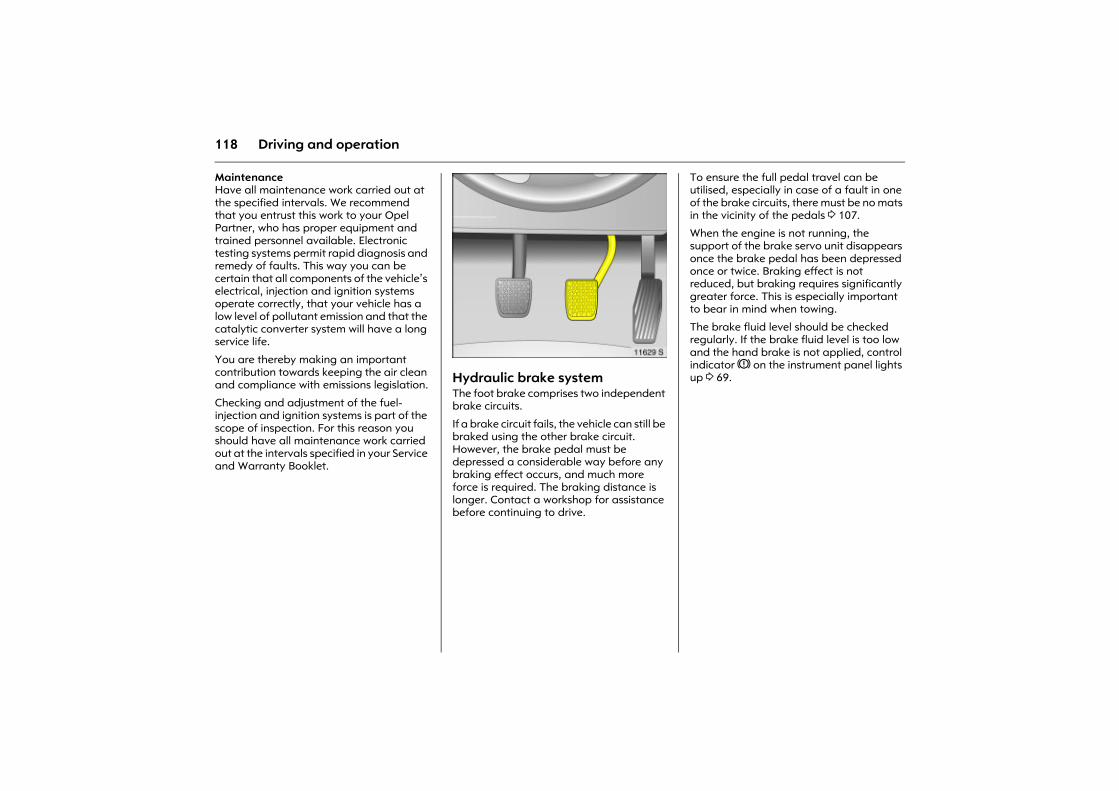
118 Driving and operation
Maintenance Have all maintenance work carried out at the specified intervals. We recommend that you entrust this work to your Opel Partner, who has proper equipment and trained personnel available. Electronic testing systems permit rapid diagnosis and remedy of faults. This way you can be certain that all components of the vehicle�s electrical, injection and ignition systems operate correctly, that your vehicle has a low level of pollutant emission and that the catalytic converter system will have a long service life.
You are thereby making an important contribution towards keeping the air clean and compliance with emissions legislation.
Checking and adjustment of the fuel-injection and ignition systems is part of the scope of inspection. For this reason you should have all maintenance work carried out at the intervals specified in your Service and Warranty Booklet.
Picture no: 11629s.tifHydraulic brake system The foot brake comprises two independent brake circuits.
If a brake circuit fails, the vehicle can still be braked using the other brake circuit. However, the brake pedal must be depressed a considerable way before any braking effect occurs, and much more force is required. The braking distance is longer. Contact a workshop for assistance before continuing to drive.
To ensure the full pedal travel can be utilised, especially in case of a fault in one of the brake circuits, there must be no mats in the vicinity of the pedals 3 107.
When the engine is not running, the support of the brake servo unit disappears once the brake pedal has been depressed once or twice. Braking effect is not reduced, but braking requires significantly greater force. This is especially important to bear in mind when towing.
The brake fluid level should be checked regularly. If the brake fluid level is too low and the hand brake is not applied, control indicator R on the instrument panel lights up 3 69.
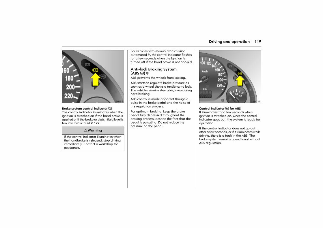
119Driving and operation
Picture no: 12482s.tifBrake system control indicator RThe control indicator illuminates when the ignition is switched on if the hand brake is applied or if the brake or clutch fluid level is too low. Brake fluid 3 179.
For vehicles with manual transmission automated 3, the control indicator flashes for a few seconds when the ignition is turned off if the hand brake is not applied.
Anti-lock Braking System (ABS u) 3 ABS prevents the wheels from locking.
ABS starts to regulate brake pressure as soon as a wheel shows a tendency to lock. The vehicle remains steerable, even during hard braking.
ABS control is made apparent though a pulse in the brake pedal and the noise of the regulation process.
For optimum braking, keep the brake pedal fully depressed throughout the braking process, despite the fact that the pedal is pulsating. Do not reduce the pressure on the pedal.
Picture no: 12147s.tifControl indicator u for ABSIt illuminates for a few seconds when ignition is switched on. Once the control indicator goes out, the system is ready for operation.
If the control indicator does not go out after a few seconds, or if it illuminates while driving, there is a fault in the ABS. The brake system remains operational without ABS regulation.
9 Warning
If the control indicator illuminates when the handbrake is released, stop driving immediately. Contact a workshop for assistance.
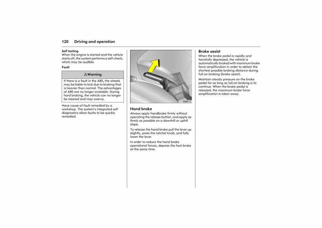
120 Driving and operation
Self testing When the engine is started and the vehicle starts off, the system performs a self-check, which may be audible.
Fault
Have cause of fault remedied by a workshop. The system�s integrated self diagnostics allow faults to be quickly remedied.
Picture no: 12481s.tifHand brake Always apply handbrake firmly without operating the release button, and apply as firmly as possible on a downhill or uphill slope.
To release the hand brake pull the lever up slightly, press the ratchet knob, and fully lower the lever.
In order to reduce the hand brake operational forces, depress the foot brake at the same time.
Brake assist When the brake pedal is rapidly and forcefully depressed, the vehicle is automatically braked with maximum brake force amplification in order to obtain the shortest possible braking distance during full-on braking (brake assist).
Maintain steady pressure on the brake pedal for as long as full-on braking is to continue. When the brake pedal is released, the maximum brake force amplification is taken away.
9 Warning
If there is a fault in the ABS, the wheels may be liable to lock due to braking that is heavier than normal. The advantages of ABS are no longer available. During hard braking, the vehicle can no longer be steered and may swerve.
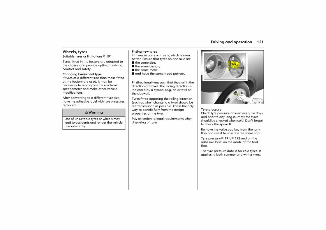
121Driving and operation
Wheels, tyres Suitable tyres or limitations 3 191.
Tyres fitted in the factory are adapted to the chassis and provide optimum driving comfort and safety.
Changing tyre/wheel typeIf tyres of a different size than those fitted at the factory are used, it may be necessary to reprogram the electronic speedometer and make other vehicle modifications.
After converting to a different tyre size, have the adhesive label with tyre pressures replaced.
Fitting new tyres Fit tyres in pairs or in sets, which is even better. Ensure that tyres on one axle are z the same size, z the same design, z the same make, z and have the same tread pattern.
Fit directional tyres such that they roll in the direction of travel. The rolling direction is indicated by a symbol (e.g. an arrow) on the sidewall.
Tyres fitted opposing the rolling direction (such as when changing a tyre) should be refitted as soon as possible. This is the only way to benefit fully from the design properties of the tyre.
Pay attention to legal requirements when disposing of tyres.
Picture no: 12117s.tifTyre pressure Check tyre pressure at least every 14 days and prior to any long journey; the tyres should be checked when cold. Don�t forget to check the spare 3.
Remove the valve cap key from the tank flap and use it to unscrew the valve cap.
Tyre pressure 3 191, 3 192 and on the adhesive label on the inside of the tank flap.
The tyre pressure data is for cold tyres. It applies to both summer and winter tyres.
9 Warning
Use of unsuitable tyres or wheels may lead to accidents and render the vehicle unroadworthy.
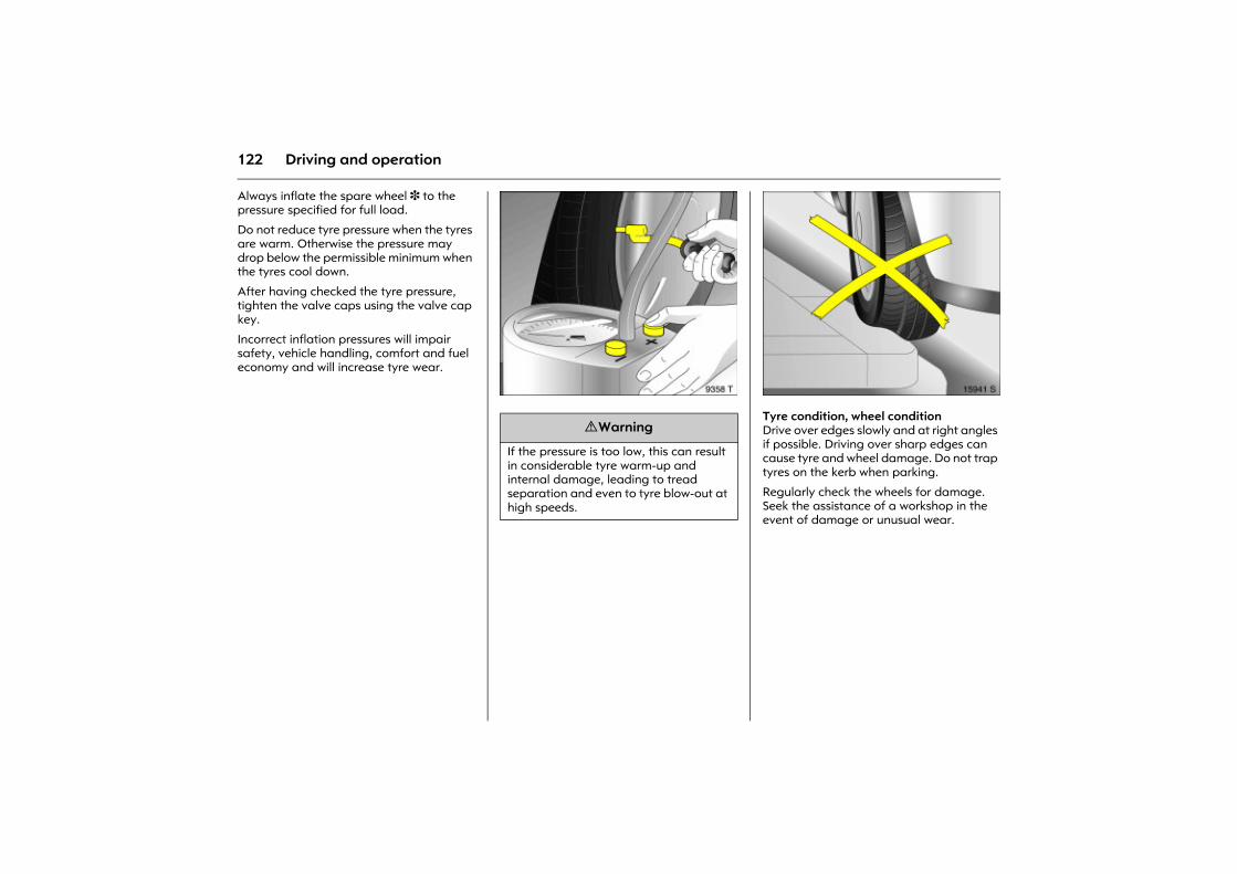
122 Driving and operation
Always inflate the spare wheel 3 to the pressure specified for full load.
Do not reduce tyre pressure when the tyres are warm. Otherwise the pressure may drop below the permissible minimum when the tyres cool down.
After having checked the tyre pressure, tighten the valve caps using the valve cap key.
Incorrect inflation pressures will impair safety, vehicle handling, comfort and fuel economy and will increase tyre wear.
Picture no: 9358t.tif Picture no: 15941s.tifTyre condition, wheel condition Drive over edges slowly and at right angles if possible. Driving over sharp edges can cause tyre and wheel damage. Do not trap tyres on the kerb when parking.
Regularly check the wheels for damage. Seek the assistance of a workshop in the event of damage or unusual wear.
9 Warning
If the pressure is too low, this can result in considerable tyre warm-up and internal damage, leading to tread separation and even to tyre blow-out at high speeds.
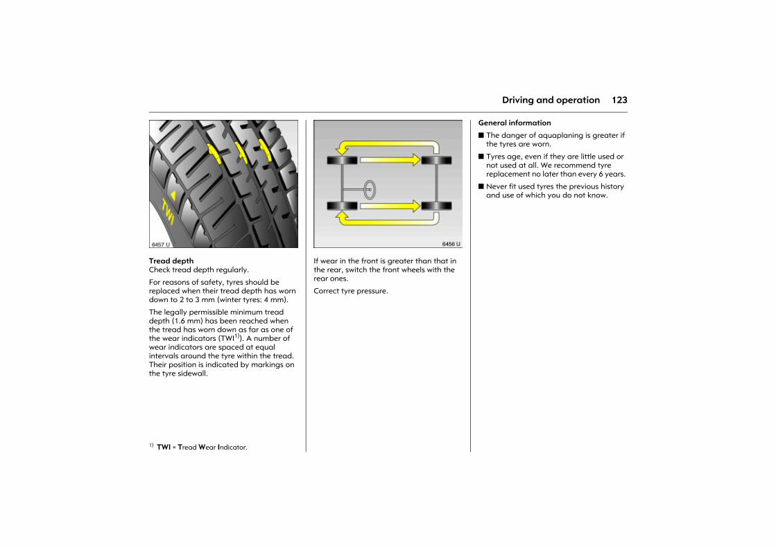
123Driving and operation
Picture no: 6457u.tifTread depth Check tread depth regularly.
For reasons of safety, tyres should be replaced when their tread depth has worn down to 2 to 3 mm (winter tyres: 4 mm).
The legally permissible minimum tread depth (1.6 mm) has been reached when the tread has worn down as far as one of the wear indicators (TWI1)). A number of wear indicators are spaced at equal intervals around the tyre within the tread. Their position is indicated by markings on the tyre sidewall.
Picture no: 6456u.tifIf wear in the front is greater than that in the rear, switch the front wheels with the rear ones.
Correct tyre pressure.
General information
z The danger of aquaplaning is greater if the tyres are worn.
z Tyres age, even if they are little used or not used at all. We recommend tyre replacement no later than every 6 years.
z Never fit used tyres the previous history and use of which you do not know.
1) TWI = Tread Wear Indicator.
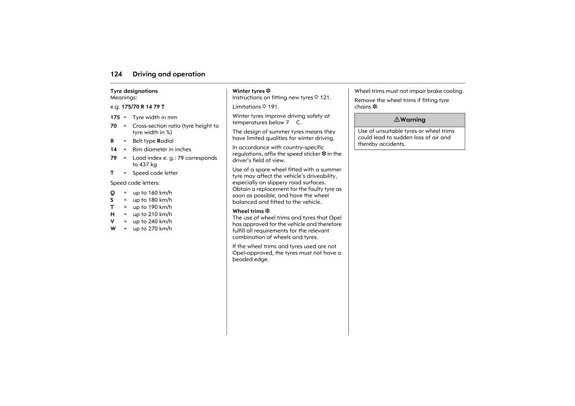
124 Driving and operation
Tyre designations Meanings:
e.g. 175/70 R 14 79 T
Speed code letters:
Winter tyres 3 Instructions on fitting new tyres 3 121.
Limitations 3 191.
Winter tyres improve driving safety at temperatures below 7 �C.
The design of summer tyres means they have limited qualities for winter driving.
In accordance with country-specific regulations, affix the speed sticker 3 in the driver�s field of view.
Use of a spare wheel fitted with a summer tyre may affect the vehicle�s driveability, especially on slippery road surfaces. Obtain a replacement for the faulty tyre as soon as possible, and have the wheel balanced and fitted to the vehicle.
Wheel trims 3 The use of wheel trims and tyres that Opel has approved for the vehicle and therefore fulfill all requirements for the relevant combination of wheels and tyres.
If the wheel trims and tyres used are not Opel-approved, the tyres must not have a beaded edge.
Wheel trims must not impair brake cooling.
Remove the wheel trims if fitting tyre chains 3.
175 = Tyre width in mm70 = Cross-section ratio (tyre height to
tyre width in %)
R = Belt type Radial14 = Rim diameter in inches79 = Load index e. g.: 79 corresponds
to 437 kgT = Speed code letter
Q = up to 160 km/hS = up to 180 km/hT = up to 190 km/hH = up to 210 km/hV = up to 240 km/hW = up to 270 km/h
9 Warning
Use of unsuitable tyres or wheel trims could lead to sudden loss of air and thereby accidents.

125Driving and operation
Picture no: 6459u.tifTyre chains 3 Limitations 3 191.
Tyre chains are only permitted on the driven wheels (front axle). They must be fitted to the tyres symmetrically in order to achieve a concentric fit.
Always use fine mesh chains that add no more than 10 mm to the tyre tread and the inboard sides (including chain lock).
Remove the wheel trims when using tyre chains 3 137.
Tyre chains may only be used at speeds up to 50 km/h. When travelling on roads that are free of snow, they may only be used for brief periods.
Tyre chains must not be used on the temporary spare wheel. If you need to use tyre chains after suffering a flat front tyre, fit the temporary spare on the rear axle and transfer one of the rear wheels to the front axle.
Roof racks 3 For safety reasons and to avoid roof damage we recommend using the Opel roof rack system that is approved for your vehicle.
Follow the usage instructions for the roof rack.
Remove the roof rack when not in use.
Remove the covers from the roof rack mounting apertures.
Driving hints 3 106.
9 Warning
Damage may lead to tyre blowout.
126 Driving and operation
Towing equipment 3 Only use towing equipment that has been approved for your vehicle. Entrust retrofitting of towing equipment to a workshop. It may be necessary to make changes that affect the cooling system, heat shields or other equipment.
Installation dimensions of towing equipment 3 197.
Towing equipment with fixed coupling ball bar 3 In the case of trailers/caravans with brake, attach break-away stopping cable to eye to right of coupling ball bar.
Caravan/trailer towingCaravan and trailer loads1)
The permissible caravan/trailer loads are vehicle and engine-dependent maximum values which must not be exceeded. The actual caravan/trailer load is the difference between the actual gross weight of the caravan/trailer and the actual coupling socket load with the caravan/trailer coupled.
The permissible caravan/trailer loads are specified in the vehicle documents. In general, they are valid for gradients up to max. 12 %.
The permitted caravan/trailer load applies up to the specified incline and up to an altitude of 1000 metres above sea level. Since engine power decreases as altitude increases because of the air becoming thinner, therefore reducing climbing ability, the permitted towing weight also decreases by 10 % for every 1000 metres of additional altitude. The towing weight does not have to be reduced when driving on roads with slight inclines (less than 8 %, e. g. motorways).
The permissible gross train weight must not be exceeded. This weight is specified on the identification plate 3 182.
Coupling socket load The coupling socket load is the load exerted by the trailer/caravan on the coupling ball. It can be varied by changing the weight distribution when loading the trailer/caravan.
The maximum permissible coupling socket load (50 kg) is specified on the towing equipment identification plate and in the vehicle documents. Always aim for the maximum load, especially in the case of heavy caravans/trailers. The coupling socket load should never fall below 25 kg.
When measuring the coupling socket load, make sure that the drawbar of the loaded trailer/caravan is at the same height as it will be when the trailer/caravan is coupled with the towing vehicle loaded. Particularly important for trailers/caravans with tandem axle.
Rear axle load during towing The permissible axle loads must not be exceeded.
1) Observe national regulations.
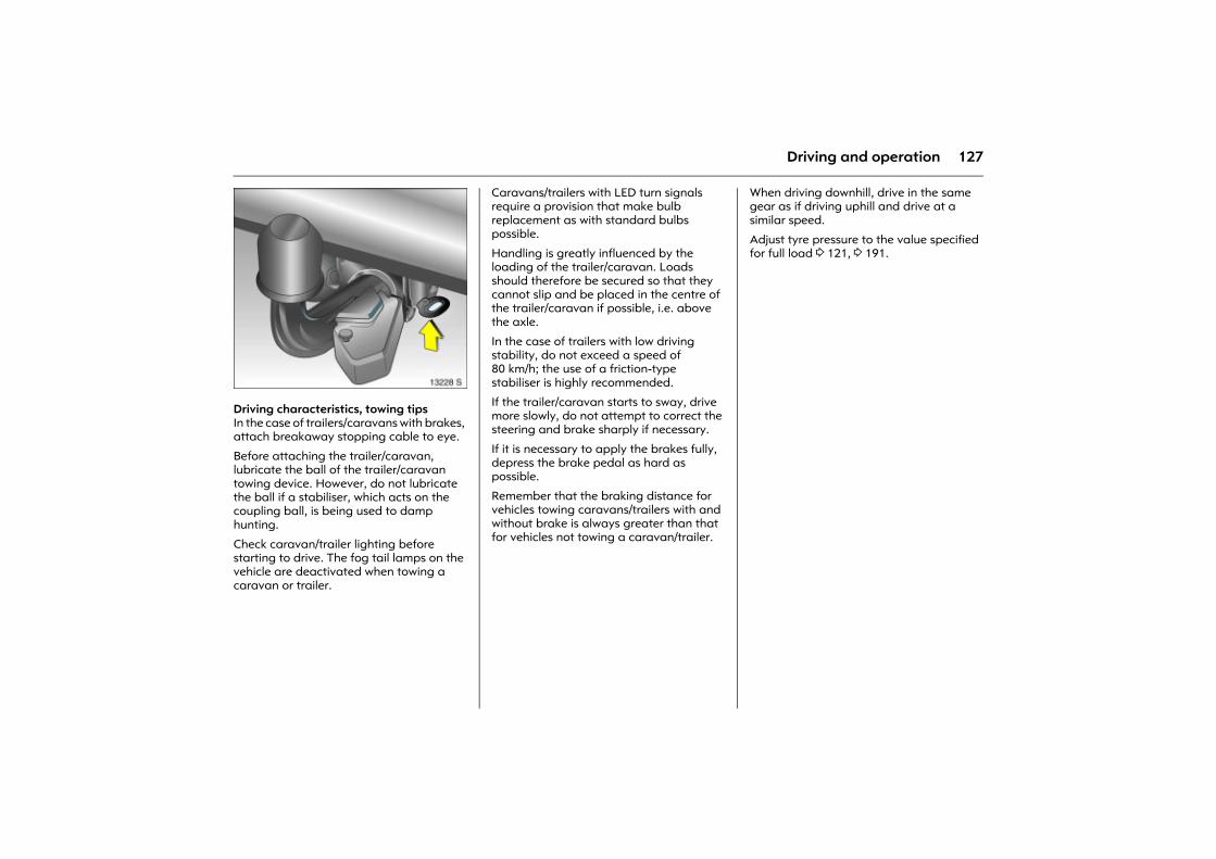
127Driving and operation
Picture no: 13228s.tifDriving characteristics, towing tips In the case of trailers/caravans with brakes, attach breakaway stopping cable to eye.
Before attaching the trailer/caravan, lubricate the ball of the trailer/caravan towing device. However, do not lubricate the ball if a stabiliser, which acts on the coupling ball, is being used to damp hunting.
Check caravan/trailer lighting before starting to drive. The fog tail lamps on the vehicle are deactivated when towing a caravan or trailer.
Caravans/trailers with LED turn signals require a provision that make bulb replacement as with standard bulbs possible.
Handling is greatly influenced by the loading of the trailer/caravan. Loads should therefore be secured so that they cannot slip and be placed in the centre of the trailer/caravan if possible, i.e. above the axle.
In the case of trailers with low driving stability, do not exceed a speed of 80 km/h; the use of a friction-type stabiliser is highly recommended.
If the trailer/caravan starts to sway, drive more slowly, do not attempt to correct the steering and brake sharply if necessary.
If it is necessary to apply the brakes fully, depress the brake pedal as hard as possible.
Remember that the braking distance for vehicles towing caravans/trailers with and without brake is always greater than that for vehicles not towing a caravan/trailer.
When driving downhill, drive in the same gear as if driving uphill and drive at a similar speed.
Adjust tyre pressure to the value specified for full load 3 121, 3 191.
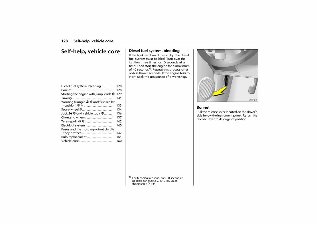
128 Self-help, vehicle care
Self-help, vehicle care Diesel fuel system, bleeding If the tank is allowed to run dry, the diesel fuel system must be bled. Turn over the ignition three times for 15 seconds at a time. Then start the engine for a maximum of 40 seconds1). Repeat this process after no less than 5 seconds. If the engine fails to start, seek the assistance of a workshop.
Picture no: 16121s.tifBonnet Pull the release lever located on the driver�s side below the instrument panel. Return the release lever to its original position.
Diesel fuel system, bleeding ............... 128 Bonnet .................................................. 128 Starting the engine with jump leads 3 129 Towing.................................................. 131 Warning triangle ̈ 3 and first-aid kit
(cushion) + 3 .................................... 133 Spare wheel 3 ...................................... 134 Jack £ 3 and vehicle tools 3 ............ 136 Changing wheels ................................. 137 Tyre repair kit 3 ................................... 142 Electrical system .................................. 145 Fuses and the most important circuits
they protect ....................................... 147 Bulb replacement ................................ 151 Vehicle care.......................................... 160
1) For technical reasons, only 30 seconds is possible for engine Z 17 DTH. Sales designation 3 184.
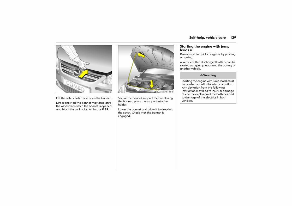
129Self-help, vehicle care
Picture no: 18097s.tifLift the safety catch and open the bonnet.
Dirt or snow on the bonnet may drop onto the windscreen when the bonnet is opened and block the air intake. Air intake 3 99.
Picture no: 15123s.tifSecure the bonnet support. Before closing the bonnet, press the support into the holder.
Lower the bonnet and allow it to drop into the catch. Check that the bonnet is engaged.
Starting the engine with jump leads 3 Do not start by quick charger or by pushing or towing.
A vehicle with a discharged battery can be started using jump leads and the battery of another vehicle.
9 Warning
Starting the engine with jump leads must be carried out with the utmost caution. Any deviation from the following instruction may lead to injury or damage due to the explosion of the batteries and to damage of the electrics in both vehicles.
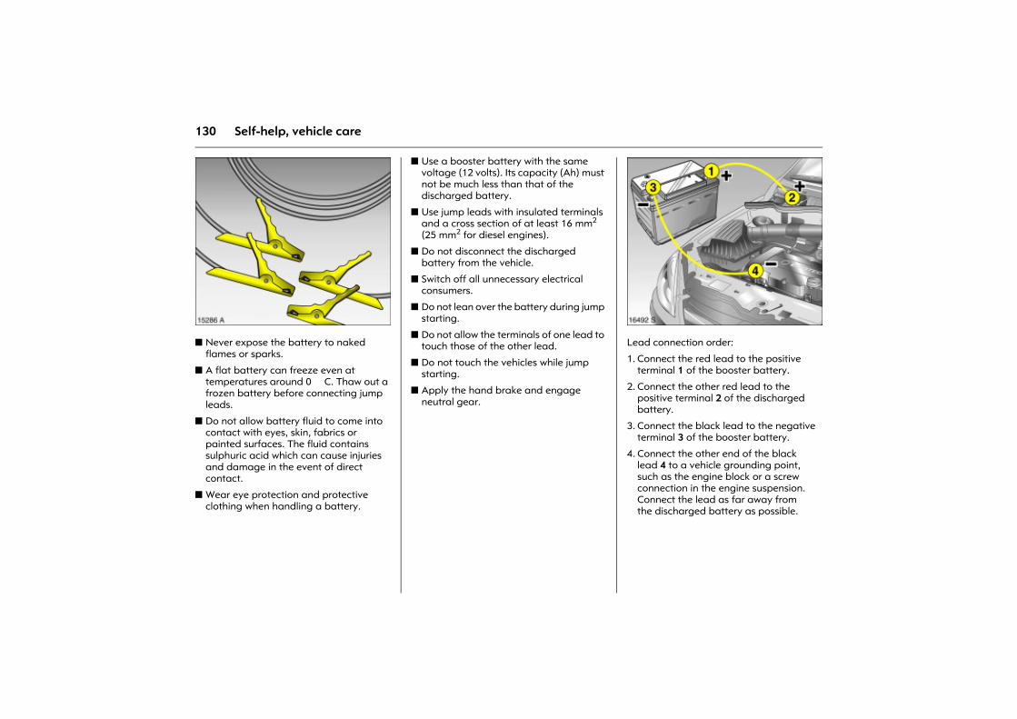
130 Self-help, vehicle care
Picture no: 15286a.tifz Never expose the battery to naked
flames or sparks.
z A flat battery can freeze even at temperatures around 0 �C. Thaw out a frozen battery before connecting jump leads.
z Do not allow battery fluid to come into contact with eyes, skin, fabrics or painted surfaces. The fluid contains sulphuric acid which can cause injuries and damage in the event of direct contact.
z Wear eye protection and protective clothing when handling a battery.
z Use a booster battery with the same voltage (12 volts). Its capacity (Ah) must not be much less than that of the discharged battery.
z Use jump leads with insulated terminals and a cross section of at least 16 mm2 (25 mm2 for diesel engines).
z Do not disconnect the discharged battery from the vehicle.
z Switch off all unnecessary electrical consumers.
z Do not lean over the battery during jump starting.
z Do not allow the terminals of one lead to touch those of the other lead.
z Do not touch the vehicles while jump starting.
z Apply the hand brake and engage neutral gear.
Picture no: 16492s.tifLead connection order:
1. Connect the red lead to the positive terminal 1 of the booster battery.
2. Connect the other red lead to the positive terminal 2 of the discharged battery.
3. Connect the black lead to the negative terminal 3 of the booster battery.
4. Connect the other end of the black lead 4 to a vehicle grounding point, such as the engine block or a screw connection in the engine suspension. Connect the lead as far away from the discharged battery as possible.
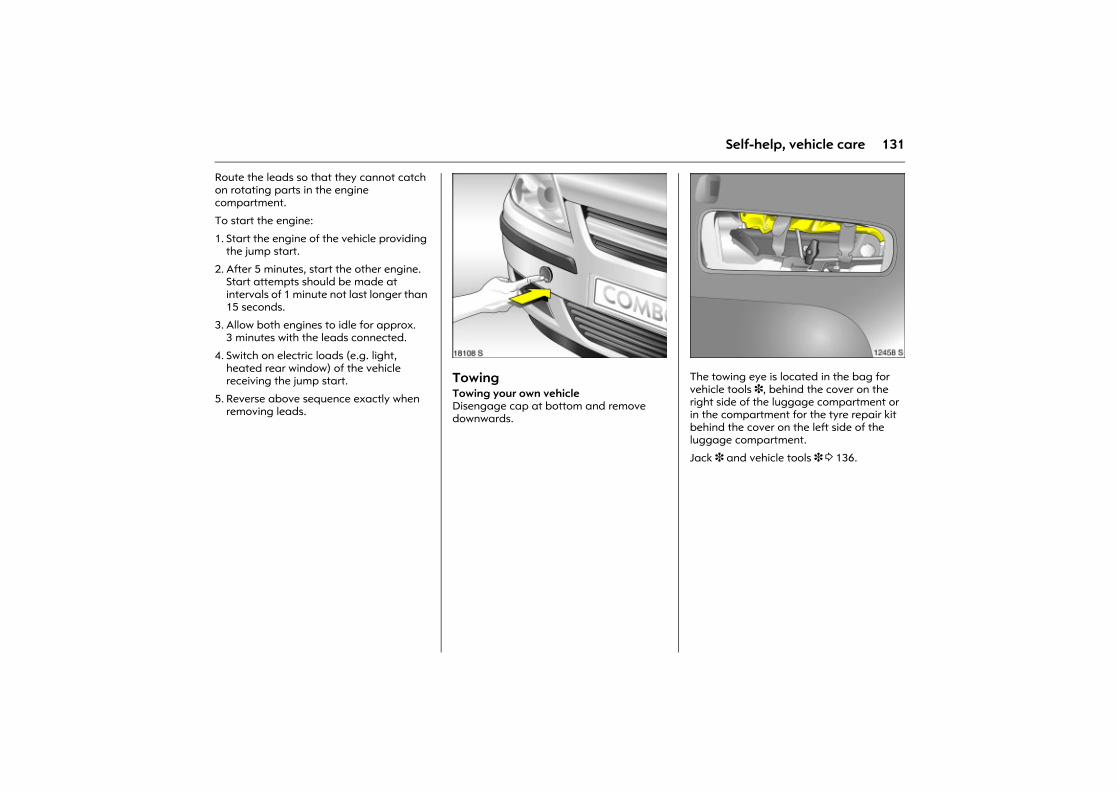
131Self-help, vehicle care
Route the leads so that they cannot catch on rotating parts in the engine compartment.
To start the engine:
1. Start the engine of the vehicle providing the jump start.
2. After 5 minutes, start the other engine. Start attempts should be made at intervals of 1 minute not last longer than 15 seconds.
3. Allow both engines to idle for approx. 3 minutes with the leads connected.
4. Switch on electric loads (e.g. light, heated rear window) of the vehicle receiving the jump start.
5. Reverse above sequence exactly when removing leads.
Picture no: 18108s.tifTowing Towing your own vehicleDisengage cap at bottom and remove downwards.
Picture no: 12458s.tifThe towing eye is located in the bag for vehicle tools 3, behind the cover on the right side of the luggage compartment or in the compartment for the tyre repair kit behind the cover on the left side of the luggage compartment.
Jack 3 and vehicle tools 3 3 136.
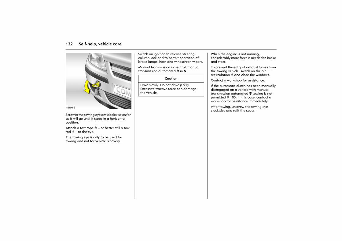
132 Self-help, vehicle care
Picture no: 18109s.tifScrew in the towing eye anticlockwise as far as it will go until it stops in a horizontal position.
Attach a tow rope 3 � or better still a tow rod 3 � to the eye.
The towing eye is only to be used for towing and not for vehicle recovery.
Switch on ignition to release steering column lock and to permit operation of brake lamps, horn and windscreen wipers.
Manual transmission in neutral; manual transmission automated 3 in N.
When the engine is not running, considerably more force is needed to brake and steer.
To prevent the entry of exhaust fumes from the towing vehicle, switch on the air recirculation 3 and close the windows.
Contact a workshop for assistance.
If the automatic clutch has been manually disengaged on a vehicle with manual transmission automated 3 towing is not permitted 3 105. In this case, contact a workshop for assistance immediately.
After towing, unscrew the towing eye clockwise and refit the cover.
Caution
Drive slowly. Do not drive jerkily. Excessive tractive force can damage the vehicle.
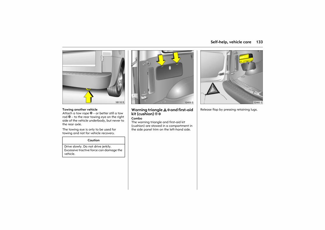
133Self-help, vehicle care
Picture no: 18110s.tifTowing another vehicle Attach a tow rope 3 � or better still a tow rod 3 � to the rear towing eye on the right side of the vehicle underbody, but never to the rear axle.
The towing eye is only to be used for towing and not for vehicle recovery.
Picture no: 12459s.tifWarning triangle ̈ 3 and first-aid kit (cushion) + 3 Combo The warning triangle and first-aid kit (cushion) are stowed in a compartment in the side panel trim on the left-hand side.
Picture no: 12460s.tifRelease flap by pressing retaining lugs.
Caution
Drive slowly. Do not drive jerkily. Excessive tractive force can damage the vehicle.
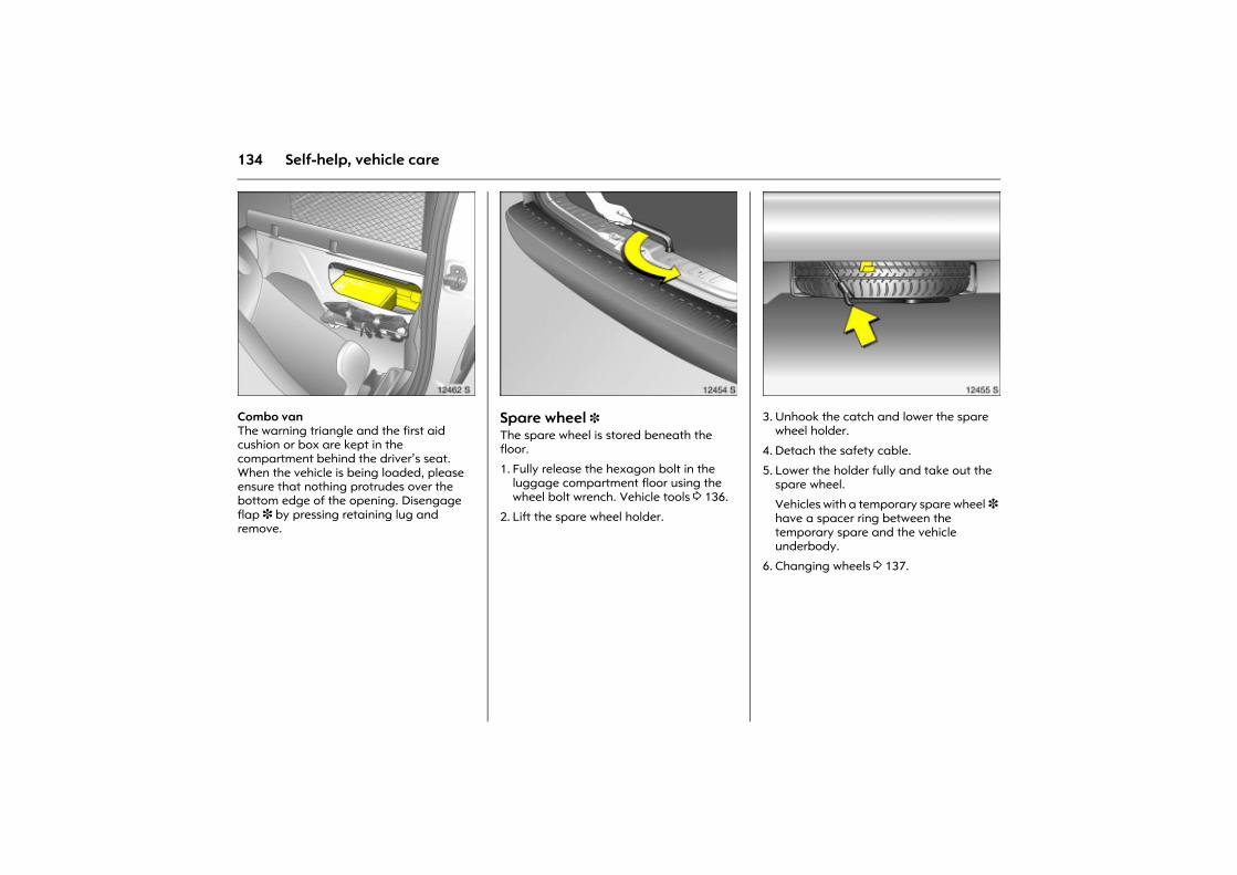
134 Self-help, vehicle care
Picture no: 12462s.tifCombo van The warning triangle and the first aid cushion or box are kept in the compartment behind the driver�s seat. When the vehicle is being loaded, please ensure that nothing protrudes over the bottom edge of the opening. Disengage flap 3 by pressing retaining lug and remove.
Picture no: 12454s.tifSpare wheel 3 The spare wheel is stored beneath the floor.
1. Fully release the hexagon bolt in the luggage compartment floor using the wheel bolt wrench. Vehicle tools 3 136.
2. Lift the spare wheel holder.
Picture no: 12455s.tif3. Unhook the catch and lower the spare
wheel holder.
4. Detach the safety cable.
5. Lower the holder fully and take out the spare wheel.
Vehicles with a temporary spare wheel 3 have a spacer ring between the temporary spare and the vehicle underbody.
6. Changing wheels 3 137.
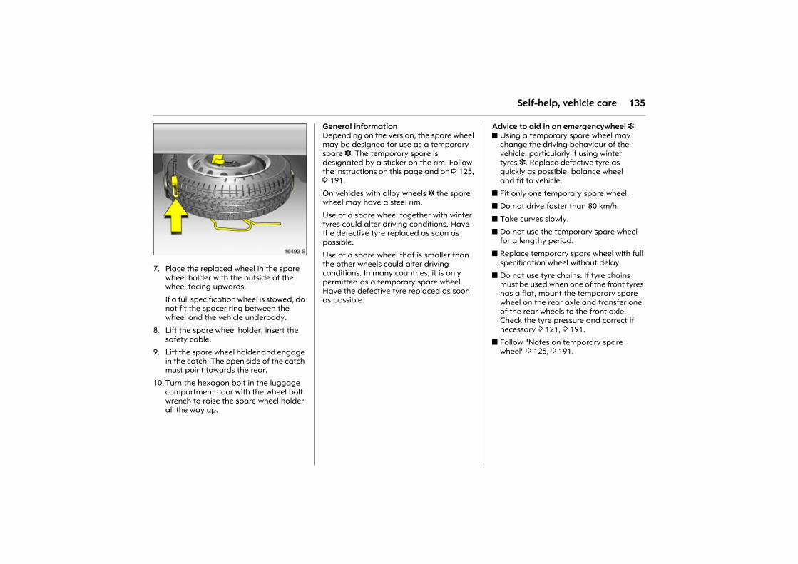
135Self-help, vehicle care
Picture no: 16493s.tif7. Place the replaced wheel in the spare
wheel holder with the outside of the wheel facing upwards.
If a full specification wheel is stowed, do not fit the spacer ring between the wheel and the vehicle underbody.
8. Lift the spare wheel holder, insert the safety cable.
9. Lift the spare wheel holder and engage in the catch. The open side of the catch must point towards the rear.
10. Turn the hexagon bolt in the luggage compartment floor with the wheel bolt wrench to raise the spare wheel holder all the way up.
General informationDepending on the version, the spare wheel may be designed for use as a temporary spare 3. The temporary spare is designated by a sticker on the rim. Follow the instructions on this page and on 3 125, 3 191.
On vehicles with alloy wheels 3 the spare wheel may have a steel rim.
Use of a spare wheel together with winter tyres could alter driving conditions. Have the defective tyre replaced as soon as possible.
Use of a spare wheel that is smaller than the other wheels could alter driving conditions. In many countries, it is only permitted as a temporary spare wheel. Have the defective tyre replaced as soon as possible.
Advice to aid in an emergencywheel 3 z Using a temporary spare wheel may
change the driving behaviour of the vehicle, particularly if using winter tyres 3. Replace defective tyre as quickly as possible, balance wheel and fit to vehicle.
z Fit only one temporary spare wheel.
z Do not drive faster than 80 km/h.
z Take curves slowly.
z Do not use the temporary spare wheel for a lengthy period.
z Replace temporary spare wheel with full specification wheel without delay.
z Do not use tyre chains. If tyre chains must be used when one of the front tyres has a flat, mount the temporary spare wheel on the rear axle and transfer one of the rear wheels to the front axle. Check the tyre pressure and correct if necessary 3 121, 3 191.
z Follow "Notes on temporary spare wheel" 3 125, 3 191.
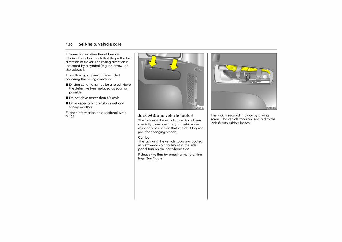
136 Self-help, vehicle care
Information on directional tyres 3 Fit directional tyres such that they roll in the direction of travel. The rolling direction is indicated by a symbol (e.g. an arrow) on the sidewall.
The following applies to tyres fitted opposing the rolling direction:
z Driving conditions may be altered. Have the defective tyre replaced as soon as possible.
z Do not drive faster than 80 km/h.
z Drive especially carefully in wet and snowy weather.
Further information on directional tyres 3 121.
Picture no: 2457s.tifJack £ 3 and vehicle tools 3The jack and the vehicle tools have been specially developed for your vehicle and must only be used on that vehicle. Only use jack for changing wheels.
Combo The jack and the vehicle tools are located in a stowage compartment in the side panel trim on the right-hand side.
Release the flap by pressing the retaining lugs. See Figure.
Picture no: 12458s.tifThe jack is secured in place by a wing screw. The vehicle tools are secured to the jack 3 with rubber bands.

137Self-help, vehicle care
Picture no: 12461s.tifCombo vanThe jack and the vehicle tools are secured behind the driver�s seat.
The jack is secured in place by a wing screw. The vehicle tools are secured to the jack with rubber bands.
Changing wheels There may be a tyre repair kit instead of a spare wheel 3 142.
Make the following preparations and observe the following information:
z Park the vehicle on a level, firm and non-skid surface. The front wheels must be in the straight-ahead position.
z Switch on the hazard warning flashers, apply the hand brake, engage first gear or reverse.
z Set up the warning triangle correctly. Warning triangle 3 133.
z Remove the spare wheel from beneath the vehicle floor 3 134.
z Never change more than one wheel at once.
z Use the jack only to change wheels.
z If the ground on which the vehicle is standing is soft, a solid board (max. 1 cm thick) should be placed under the jack.
z Block the wheel diagonally opposite the wheel to be changed by placing wedge blocks or equivalent in front and behind the wheel.
z No people or animals may be in the vehicle when it is jacked up.
z Never crawl under a jacked-up vehicle.
z Do not start the vehicle when it is raised on the jack.
z Before screwing in the wheel bolts, clean them and lightly coat the taper of each wheel bolt with commercially available grease.
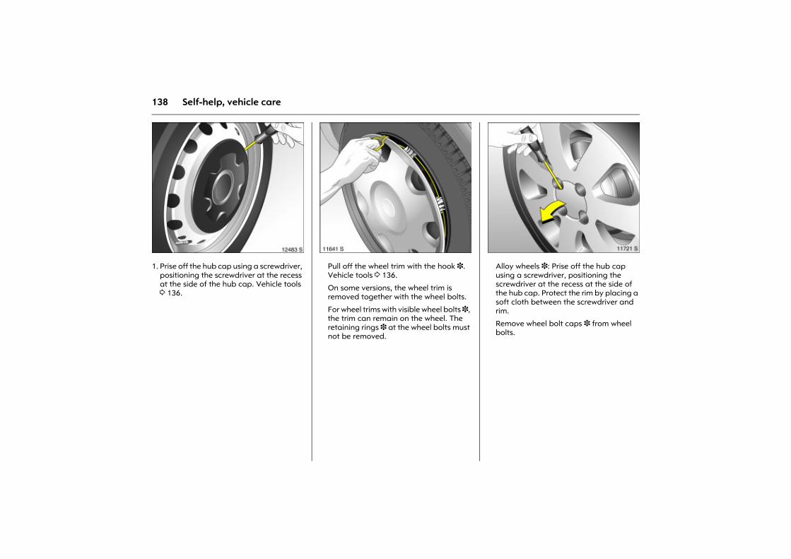
138 Self-help, vehicle care
Picture no: 12483s.tif1. Prise off the hub cap using a screwdriver,
positioning the screwdriver at the recess at the side of the hub cap. Vehicle tools 3 136.
Picture no: 11641s.tifPull off the wheel trim with the hook 3. Vehicle tools 3 136.
On some versions, the wheel trim is removed together with the wheel bolts.
For wheel trims with visible wheel bolts 3, the trim can remain on the wheel. The retaining rings 3 at the wheel bolts must not be removed.
Picture no: 11721s.tifAlloy wheels 3: Prise off the hub cap using a screwdriver, positioning the screwdriver at the recess at the side of the hub cap. Protect the rim by placing a soft cloth between the screwdriver and rim.
Remove wheel bolt caps 3 from wheel bolts.
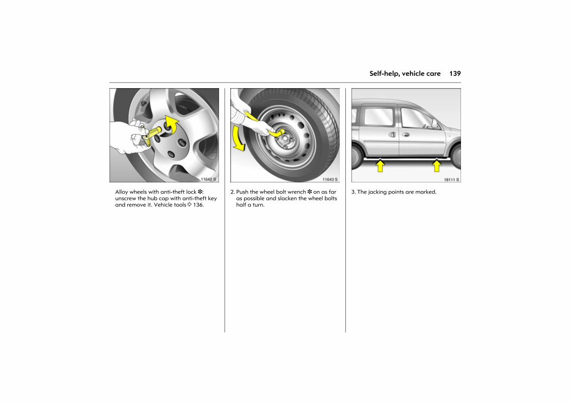
139Self-help, vehicle care
Picture no: 11642s.tifAlloy wheels with anti-theft lock 3: unscrew the hub cap with anti-theft key and remove it. Vehicle tools 3 136.
Picture no: 11643s.tif2. Push the wheel bolt wrench 3 on as far
as possible and slacken the wheel bolts half a turn.
Picture no: 18111s.tif3. The jacking points are marked.
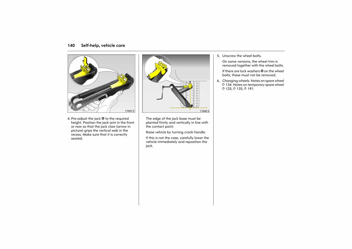
140 Self-help, vehicle care
Picture no: 11645s.tif4. Pre-adjust the jack 3 to the required
height. Position the jack arm in the front or rear so that the jack claw (arrow in picture) grips the vertical web in the recess. Make sure that it is correctly seated.
Picture no: 11646s.tifThe edge of the jack base must be planted firmly and vertically in line with the contact point.
Raise vehicle by turning crank handle.
If this is not the case, carefully lower the vehicle immediately and reposition the jack.
5. Unscrew the wheel bolts.
On some versions, the wheel trim is removed together with the wheel bolts.
If there are lock washers 3 on the wheel bolts, these must not be removed.
6. Changing wheels. Notes on spare wheel 3 134. Notes on temporary spare wheel 3 125, 3 135, 3 191.
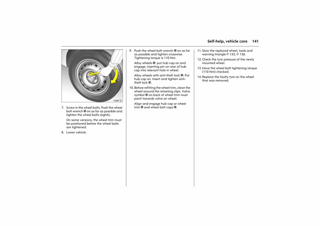
141Self-help, vehicle care
Picture no: 11647s.tif7. Screw in the wheel bolts. Push the wheel
bolt wrench 3 on as far as possible and tighten the wheel bolts slightly.
On some versions, the wheel trim must be positioned before the wheel bolts are tightened.
8. Lower vehicle.
9. Push the wheel bolt wrench 3 on as far as possible and tighten crosswise. Tightening torque is 110 Nm.
Alloy wheels 3: put hub cap on and engage, inserting pin on rear of hub cap into relevant hole in wheel.
Alloy wheels with anti-theft lock 3: Put hub cap on. Insert and tighten anti-theft lock 3.
10. Before refitting the wheel trim, clean the wheel around the retaining clips. Valve symbol 3 on back of wheel trim must point towards valve on wheel.
Align and engage hub cap or wheel trim 3 and wheel bolt caps 3.
11. Stow the replaced wheel, tools and warning triangle 3 133, 3 136.
12. Check the tyre pressure of the newly mounted wheel.
13. Have the wheel bolt tightening torque (110 Nm) checked.
14. Replace the faulty tyre on the wheel that was removed.
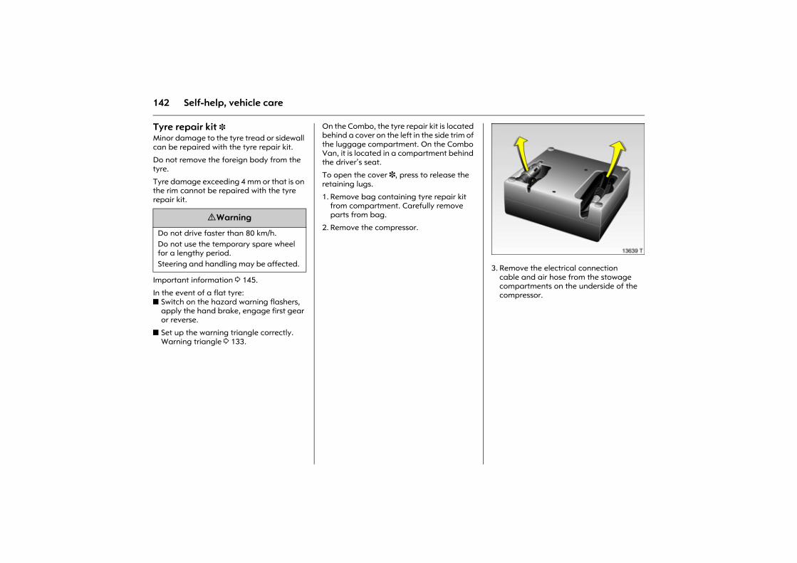
142 Self-help, vehicle care
Tyre repair kit 3 Minor damage to the tyre tread or sidewall can be repaired with the tyre repair kit.
Do not remove the foreign body from the tyre.
Tyre damage exceeding 4 mm or that is on the rim cannot be repaired with the tyre repair kit.
Important information 3 145.
In the event of a flat tyre: z Switch on the hazard warning flashers,
apply the hand brake, engage first gear or reverse.
z Set up the warning triangle correctly. Warning triangle 3 133.
On the Combo, the tyre repair kit is located behind a cover on the left in the side trim of the luggage compartment. On the Combo Van, it is located in a compartment behind the driver�s seat.
To open the cover 3, press to release the retaining lugs.
1. Remove bag containing tyre repair kit from compartment. Carefully remove parts from bag.
2. Remove the compressor.
Picture no: 13639T.tif3. Remove the electrical connection
cable and air hose from the stowage compartments on the underside of the compressor.
9 Warning
Do not drive faster than 80 km/h. Do not use the temporary spare wheel for a lengthy period. Steering and handling may be affected.
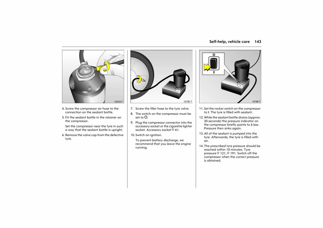
143Self-help, vehicle care
Picture no: 15319t.tif4. Screw the compressor air hose to the
connection on the sealant bottle.
5. Fit the sealant bottle in the retainer on the compressor.
Set the compressor near the tyre in such a way that the sealant bottle is upright.
6. Remove the valve cap from the defective tyre.
Picture no: 15795t.tif7. Screw the filler hose to the tyre valve.
8. The switch on the compressor must be set to §.
9. Plug the compressor connector into the accessory socket or the cigarette lighter socket. Accessory socket 3 61.
10. Switch on ignition.
To prevent battery discharge, we recommend that you leave the engine running.
Picture no: 15796t.tif11. Set the rocker switch on the compressor
to I. The tyre is filled with sealant.
12. While the sealant bottle drains (approx. 30 seconds) the pressure indicator on the compressor briefly points to 6 bar. Pressure then sinks again.
13. All of the sealant is pumped into the tyre. Afterwards, the tyre is filled with air.
14. The prescribed tyre pressure should be reached within 10 minutes. Tyre pressure 3 121, 3 191. Switch off the compressor when the correct pressure is obtained.
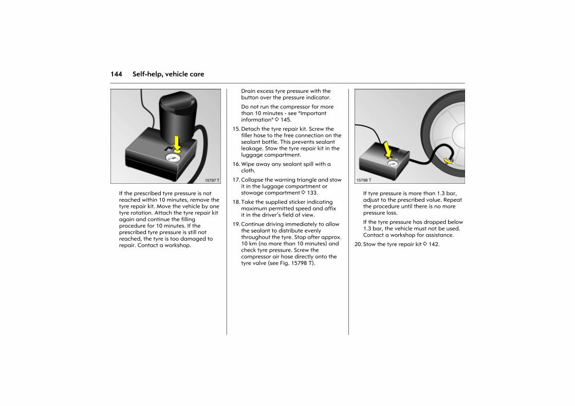
144 Self-help, vehicle care
Picture no: 15797t.tifIf the prescribed tyre pressure is not reached within 10 minutes, remove the tyre repair kit. Move the vehicle by one tyre rotation. Attach the tyre repair kit again and continue the filling procedure for 10 minutes. If the prescribed tyre pressure is still not reached, the tyre is too damaged to repair. Contact a workshop.
Drain excess tyre pressure with the button over the pressure indicator.
Do not run the compressor for more than 10 minutes - see "Important information" 3 145.
15. Detach the tyre repair kit. Screw the filler hose to the free connection on the sealant bottle. This prevents sealant leakage. Stow the tyre repair kit in the luggage compartment.
16. Wipe away any sealant spill with a cloth.
17. Collapse the warning triangle and stow it in the luggage compartment or stowage compartment 3 133.
18. Take the supplied sticker indicating maximum permitted speed and affix it in the driver�s field of view.
19. Continue driving immediately to allow the sealant to distribute evenly throughout the tyre. Stop after approx. 10 km (no more than 10 minutes) and check tyre pressure. Screw the compressor air hose directly onto the tyre valve (see Fig. 15798 T).
Picture no: 15798t.tifIf tyre pressure is more than 1.3 bar, adjust to the prescribed value. Repeat the procedure until there is no more pressure loss.
If the tyre pressure has dropped below 1.3 bar, the vehicle must not be used. Contact a workshop for assistance.
20. Stow the tyre repair kit 3 142.
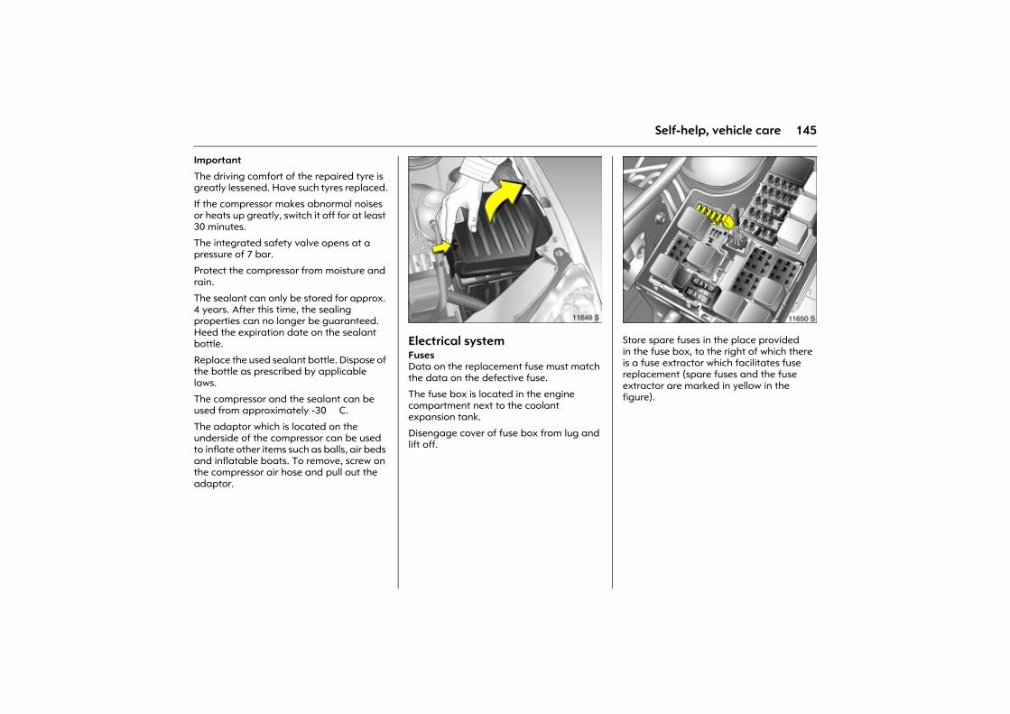
145Self-help, vehicle care
Important
The driving comfort of the repaired tyre is greatly lessened. Have such tyres replaced.
If the compressor makes abnormal noises or heats up greatly, switch it off for at least 30 minutes.
The integrated safety valve opens at a pressure of 7 bar.
Protect the compressor from moisture and rain.
The sealant can only be stored for approx. 4 years. After this time, the sealing properties can no longer be guaranteed. Heed the expiration date on the sealant bottle.
Replace the used sealant bottle. Dispose of the bottle as prescribed by applicable laws.
The compressor and the sealant can be used from approximately -30 �C.
The adaptor which is located on the underside of the compressor can be used to inflate other items such as balls, air beds and inflatable boats. To remove, screw on the compressor air hose and pull out the adaptor.
Picture no: 11648s.tifElectrical system FusesData on the replacement fuse must match the data on the defective fuse.
The fuse box is located in the engine compartment next to the coolant expansion tank.
Disengage cover of fuse box from lug and lift off.
Picture no: 11650s.tifStore spare fuses in the place provided in the fuse box, to the right of which there is a fuse extractor which facilitates fuse replacement (spare fuses and the fuse extractor are marked in yellow in the figure).
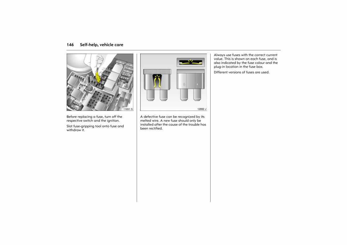
146 Self-help, vehicle care
Picture no: 11651s.tifBefore replacing a fuse, turn off the respective switch and the ignition.
Slot fuse-gripping tool onto fuse and withdraw it.
Picture no: 12892j.tifA defective fuse can be recognized by its melted wire. A new fuse should only be installed after the cause of the trouble has been rectified.
Always use fuses with the correct current value. This is shown on each fuse, and is also indicated by the fuse colour and the plug-in location in the fuse box.
Different versions of fuses are used.
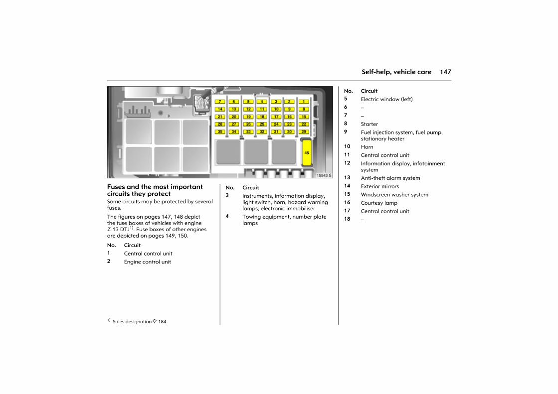
147Self-help, vehicle care
Picture no: 15543s.tifFuses and the most important circuits they protectSome circuits may be protected by several fuses.
The figures on pages 147, 148 depict the fuse boxes of vehicles with engine Z 13 DTJ1). Fuse boxes of other engines are depicted on pages 149, 150.
Picture no:
1) Sales designation 3 184.
No. Circuit1 Central control unit2 Engine control unit
No. Circuit3 Instruments, information display,
light switch, horn, hazard warning lamps, electronic immobiliser
4 Towing equipment, number plate lamps
No. Circuit5 Electric window (left)6 �7 �8 Starter9 Fuel injection system, fuel pump,
stationary heater10 Horn11 Central control unit12 Information display, infotainment
system13 Anti-theft alarm system14 Exterior mirrors15 Windscreen washer system16 Courtesy lamp17 Central control unit18 �
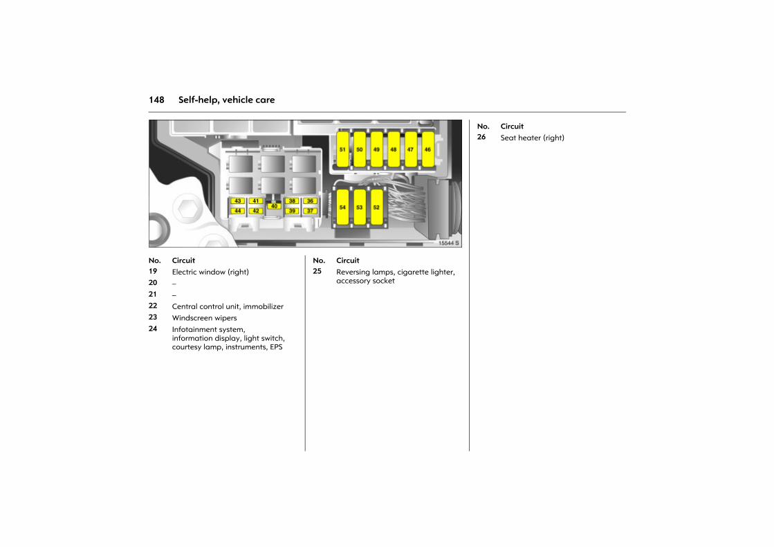
148 Self-help, vehicle care
Picture no: 15544s.tif Picture no: No. Circuit19 Electric window (right)20 �21 �22 Central control unit, immobilizer 23 Windscreen wipers24 Infotainment system,
information display, light switch, courtesy lamp, instruments, EPS
No. Circuit25 Reversing lamps, cigarette lighter,
accessory socket
No. Circuit26 Seat heater (right)
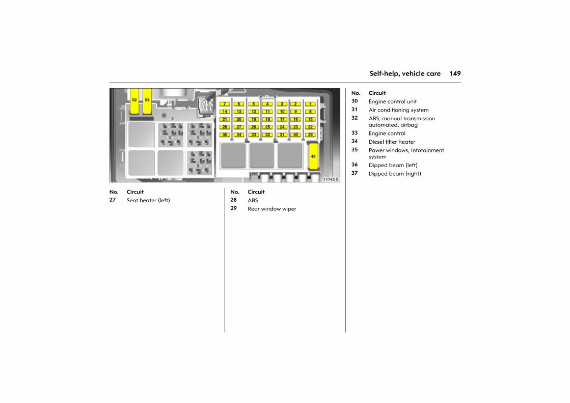
149Self-help, vehicle care
Picture no: 11743s.tif Picture no: No. Circuit27 Seat heater (left)
No. Circuit28 ABS29 Rear window wiper
No. Circuit30 Engine control unit31 Air conditioning system32 ABS, manual transmission
automated, airbag 33 Engine control34 Diesel filter heater35 Power windows, Infotainment
system36 Dipped beam (left)37 Dipped beam (right)
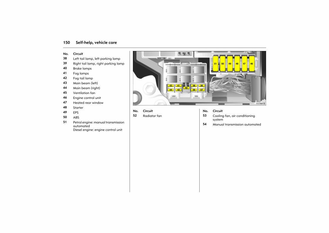
150 Self-help, vehicle care
No. Circuit38 Left tail lamp, left parking lamp39 Right tail lamp, right parking lamp40 Brake lamps41 Fog lamps42 Fog tail lamp43 Main beam (left)44 Main beam (right)45 Ventilation fan46 Engine control unit47 Heated rear window48 Starter49 EPS50 ABS 51 Petrol engine: manual transmission
automatedDiesel engine: engine control unit
Picture no: 11744s.tif Picture no: No. Circuit52 Radiator fan
No. Circuit53 Cooling fan, air conditioning
system54 Manual transmission automated
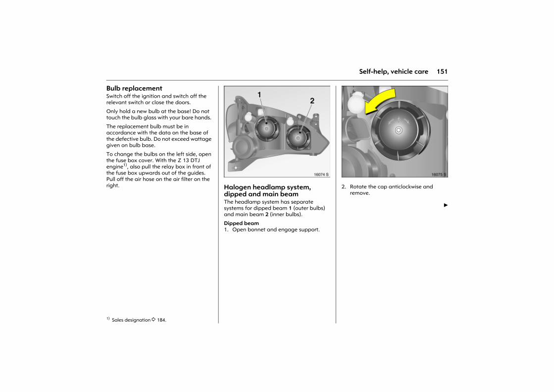
151Self-help, vehicle care
Bulb replacement Switch off the ignition and switch off the relevant switch or close the doors.
Only hold a new bulb at the base! Do not touch the bulb glass with your bare hands.
The replacement bulb must be in accordance with the data on the base of the defective bulb. Do not exceed wattage given on bulb base.
To change the bulbs on the left side, open the fuse box cover. With the Z 13 DTJ engine1), also pull the relay box in front of the fuse box upwards out of the guides. Pull off the air hose on the air filter on the right.
Picture no: 16074s.tifHalogen headlamp system, dipped and main beam The headlamp system has separate systems for dipped beam 1 (outer bulbs) and main beam 2 (inner bulbs).
Dipped beam 1. Open bonnet and engage support.
Picture no: 16075s.tif2. Rotate the cap anticlockwise and
remove.
6
1) Sales designation 3 184.
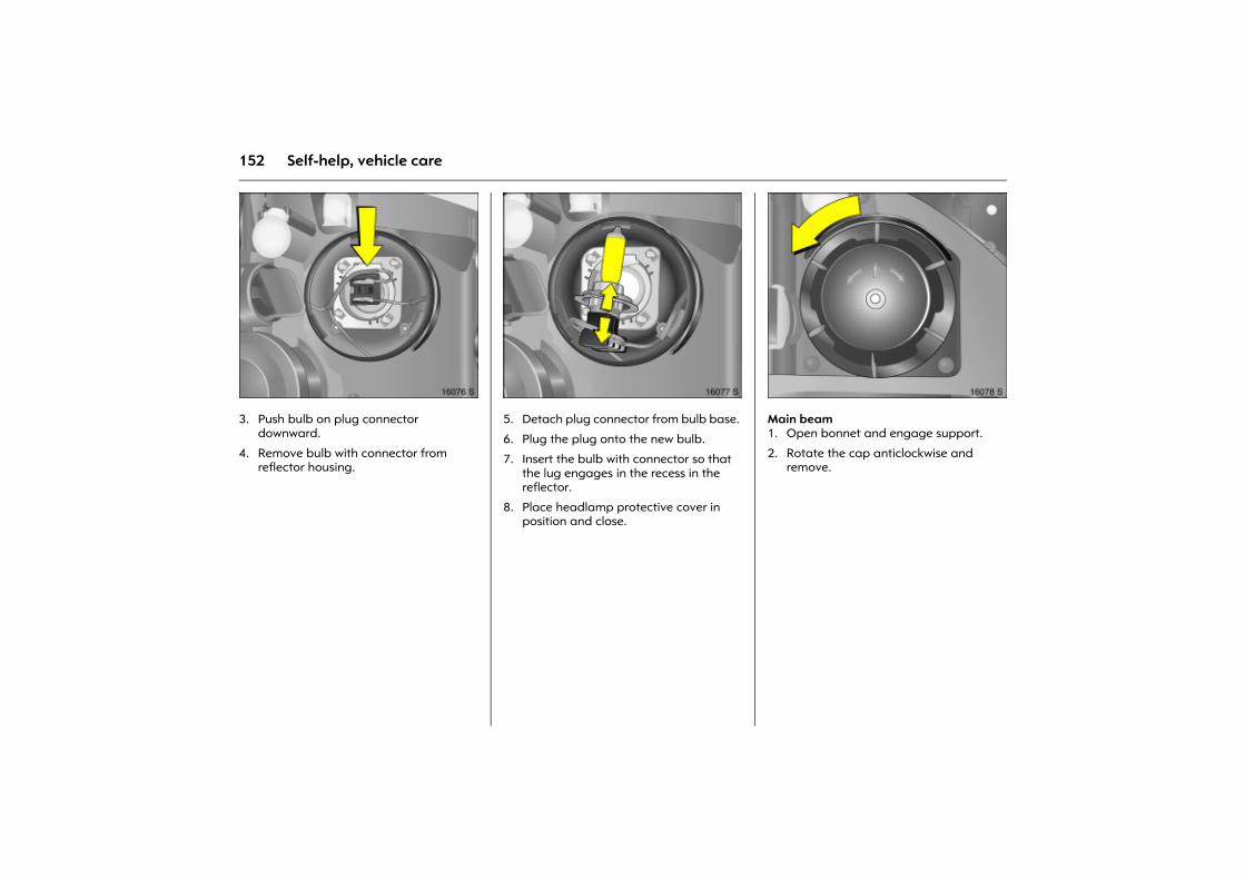
152 Self-help, vehicle care
Picture no: 16076s.tif3. Push bulb on plug connector
downward.
4. Remove bulb with connector from reflector housing.
Picture no: 16077s.tif5. Detach plug connector from bulb base.
6. Plug the plug onto the new bulb.
7. Insert the bulb with connector so that the lug engages in the recess in the reflector.
8. Place headlamp protective cover in position and close.
Picture no: 16078s.tifMain beam 1. Open bonnet and engage support.
2. Rotate the cap anticlockwise and remove.
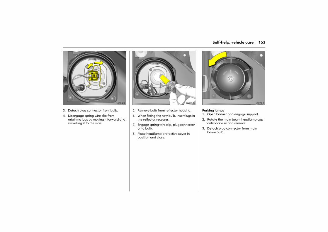
153Self-help, vehicle care
Picture no: 16079s.tif3. Detach plug connector from bulb.
4. Disengage spring wire clip from retaining lugs by moving it forward and swivelling it to the side.
Picture no: 16080s.tif5. Remove bulb from reflector housing.
6. When fitting the new bulb, insert lugs in the reflector recesses.
7. Engage spring wire clip, plug connector onto bulb.
8. Place headlamp protective cover in position and close.
Picture no: 16078s.tifParking lamps 1. Open bonnet and engage support.
2. Rotate the main beam headlamp cap anticlockwise and remove.
3. Detach plug connector from main beam bulb.
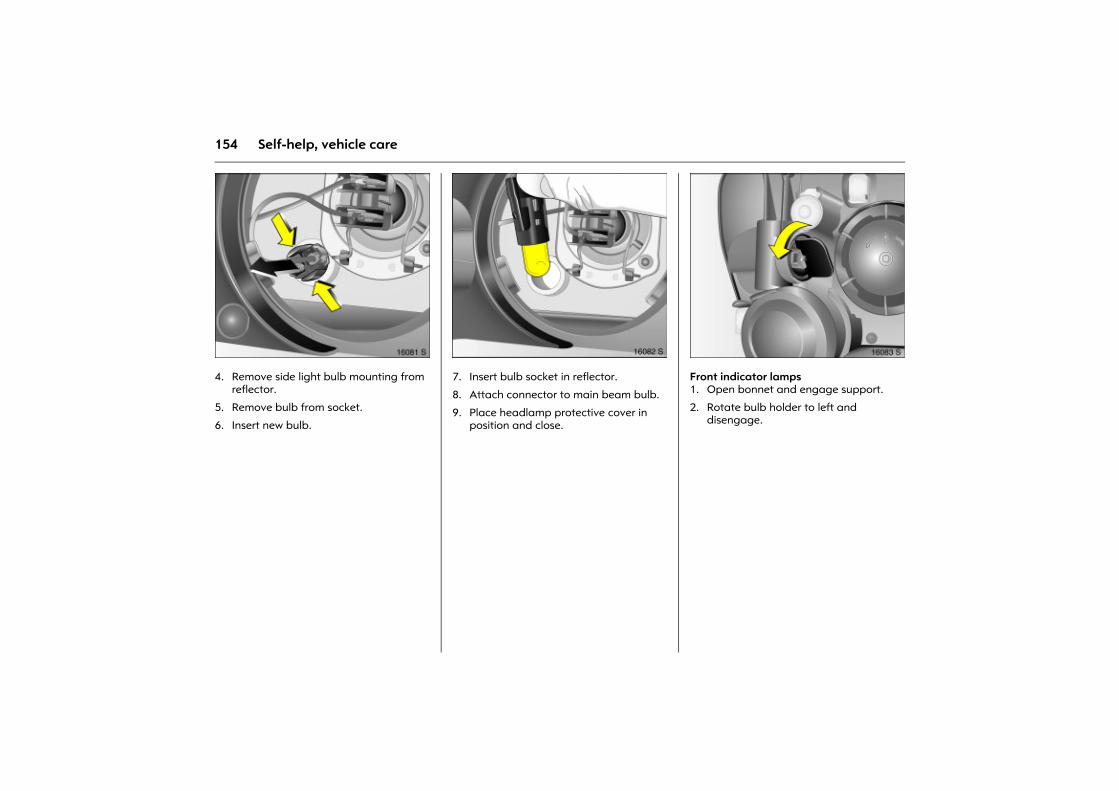
154 Self-help, vehicle care
Picture no: 16081s.tif4. Remove side light bulb mounting from
reflector.
5. Remove bulb from socket.
6. Insert new bulb.
Picture no: 16082s.tif7. Insert bulb socket in reflector.
8. Attach connector to main beam bulb.
9. Place headlamp protective cover in position and close.
Picture no: 16083s.tifFront indicator lamps 1. Open bonnet and engage support.
2. Rotate bulb holder to left and disengage.
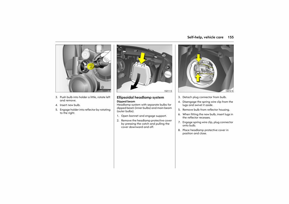
155Self-help, vehicle care
Picture no: 16084s.tif3. Push bulb into holder a little, rotate left
and remove.
4. Insert new bulb.
5. Engage holder into reflector by rotating to the right.
Picture no: 15211s.tifEllipsoidal headlamp systemDipped beam Headlamp system with separate bulbs for dipped beam (inner bulbs) and main beam (outer bulbs).
1. Open bonnet and engage support.
2. Remove the headlamp protective cover by pressing the catch and pulling the cover downward and off.
Picture no: 15212s.tif3. Detach plug connector from bulb.
4. Disengage the spring wire clip from the lugs and swivel it aside.
5. Remove bulb from reflector housing.
6. When fitting the new bulb, insert lugs in the reflector recesses.
7. Engage spring wire clip, plug connector onto bulb.
8. Place headlamp protective cover in position and close.
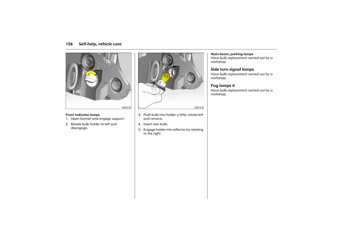
156 Self-help, vehicle care
Picture no: 15213s.tifFront indicator lamps 1. Open bonnet and engage support.
2. Rotate bulb holder to left and disengage.
Picture no: 15214s.tif3. Push bulb into holder a little, rotate left
and remove.
4. Insert new bulb.
5. Engage holder into reflector by rotating to the right.
Main beam, parking lamps Have bulb replacement carried out by a workshop.
Side turn signal lamps Have bulb replacement carried out by a workshop.
Fog lamps 3 Have bulb replacement carried out by a workshop.
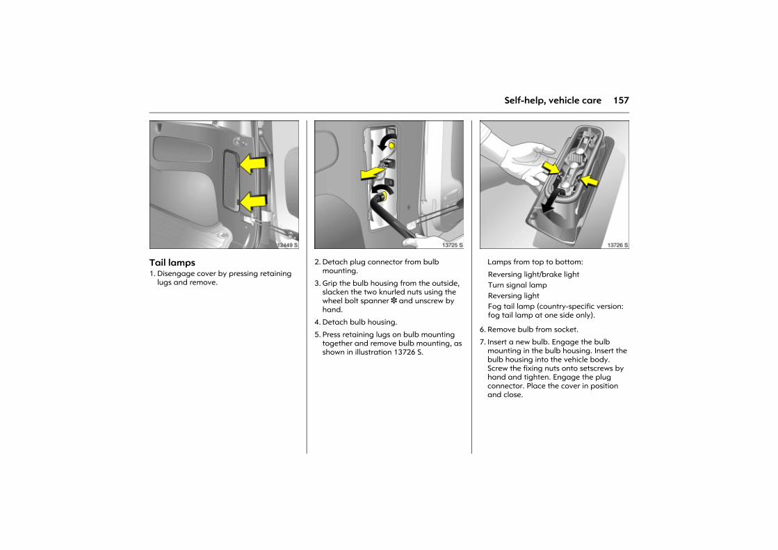
157Self-help, vehicle care
Picture no: 12449s.tifTail lamps 1. Disengage cover by pressing retaining
lugs and remove.
Picture no: 13725s.tif2. Detach plug connector from bulb
mounting.
3. Grip the bulb housing from the outside, slacken the two knurled nuts using the wheel bolt spanner 3 and unscrew by hand.
4. Detach bulb housing.
5. Press retaining lugs on bulb mounting together and remove bulb mounting, as shown in illustration 13726 S.
Picture no: 13726s.tifLamps from top to bottom:
6. Remove bulb from socket.
7. Insert a new bulb. Engage the bulb mounting in the bulb housing. Insert the bulb housing into the vehicle body. Screw the fixing nuts onto setscrews by hand and tighten. Engage the plug connector. Place the cover in position and close.
Reversing light/brake light Turn signal lampReversing lightFog tail lamp (country-specific version: fog tail lamp at one side only).
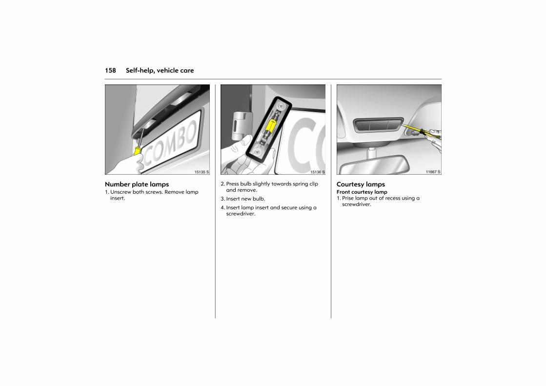
158 Self-help, vehicle care
Picture no: 15135s.tifNumber plate lamps 1. Unscrew both screws. Remove lamp
insert.
Picture no: 15136s.tif2. Press bulb slightly towards spring clip
and remove.
3. Insert new bulb.
4. Insert lamp insert and secure using a screwdriver.
Picture no: 11667s.tifCourtesy lamps Front courtesy lamp 1. Prise lamp out of recess using a
screwdriver.
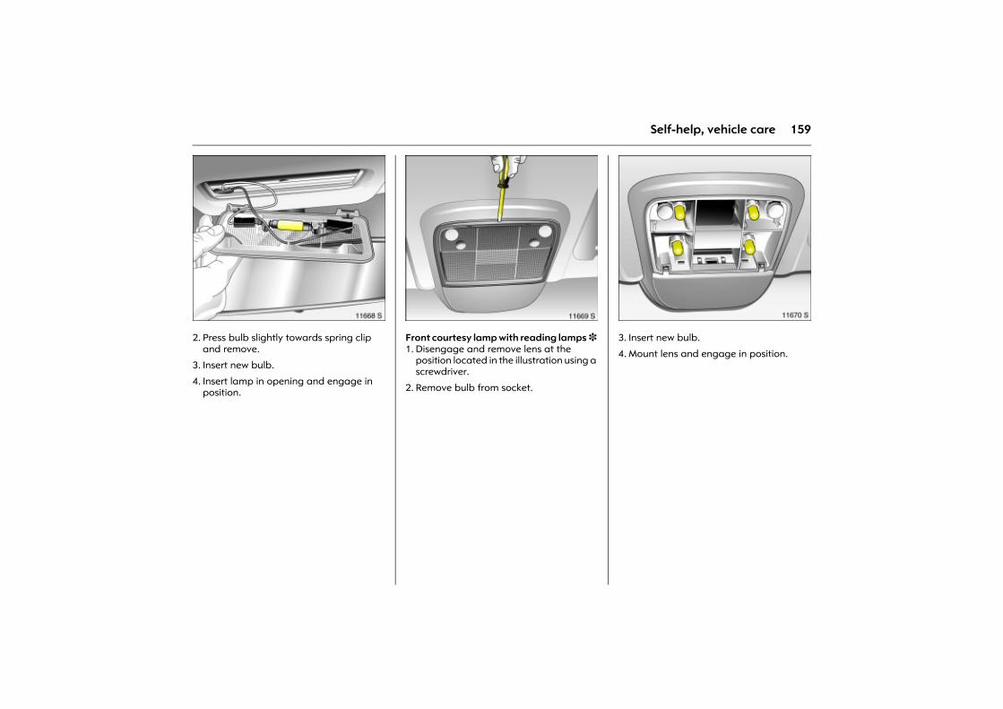
159Self-help, vehicle care
Picture no: 11668s.tif2. Press bulb slightly towards spring clip
and remove.
3. Insert new bulb.
4. Insert lamp in opening and engage in position.
Picture no: 11669s.tifFront courtesy lamp with reading lamps 3 1. Disengage and remove lens at the
position located in the illustration using a screwdriver.
2. Remove bulb from socket.
Picture no: 11670s.tif3. Insert new bulb.
4. Mount lens and engage in position.
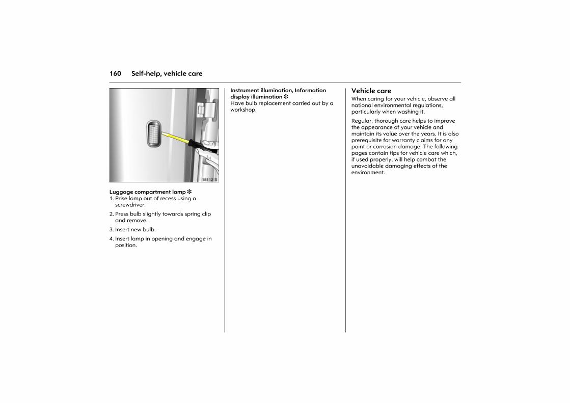
160 Self-help, vehicle care
Picture no: 18112s.tifLuggage compartment lamp 3 1. Prise lamp out of recess using a
screwdriver.
2. Press bulb slightly towards spring clip and remove.
3. Insert new bulb.
4. Insert lamp in opening and engage in position.
Instrument illumination, Information display illumination 3 Have bulb replacement carried out by a workshop.
Vehicle careWhen caring for your vehicle, observe all national environmental regulations, particularly when washing it.
Regular, thorough care helps to improve the appearance of your vehicle and maintain its value over the years. It is also prerequisite for warranty claims for any paint or corrosion damage. The following pages contain tips for vehicle care which, if used properly, will help combat the unavoidable damaging effects of the environment.
161Self-help, vehicle care
Washing The paintwork of your vehicle is exposed to environmental influences. Wash and wax your vehicle regularly. When using automatic car washes, select a programme that includes waxing.
Bird droppings, dead insects, resin, pollen and the like should be cleaned off immediately, as they contain aggressive constituents which can cause paint damage.
When using a car wash, follow the car-wash manufacturer�s instructions. Switch off the windscreen wipers 3. Unscrew the antenna 3 and remove the roof rack 3.
If you wash your vehicle by hand, make sure that the insides of the wings are also thoroughly rinsed out.
Clean edges and folds on opened doors and flaps as well as the areas they cover.
Thoroughly rinse off and leather-off the vehicle. Rinse leather frequently. Use separate leathers for paint and window surfaces: remnants of wax on the windows will impair vision.
Do not use hard objects to remove spots of tar. Use tar removal spray on painted surfaces.
Polishing and waxing Wax the vehicle regularly (at the latest when water no longer beads). Otherwise, the paintwork will dry out.
Polishing is necessary only if the paint has become dull or if solid deposits have become attached to it.
Paintwork polish with silicone forms a protective film, making waxing unnecessary.
Plastic body parts should not be treated with wax and polish.
Wheels and tyresDo not use high-pressure jet cleaners.
Clean wheels with a pH-neutral wheel cleaner.
Wheels are painted and can be treated with the same agents as the body.
Paintwork damage Rectify minor paintwork damage with a touch-up pen before rust forms. Have more extensive damage or rust areas repaired by a workshop.
162 Self-help, vehicle care
Exterior lights Headlamp and other lamp lens are made of plastic. Do not use any abrasive or caustic agents, do not use an ice scraper, and do not clean them dry.
Plastic and rubber parts Plastic and rubber parts can be cleaned with the same cleaner as used to clean the body. Use interior cleaner if necessary. Do not use any other agent. Avoid solvents and petrol in particular. Do not use high-pressure jet cleaners.
Interior and upholstery Clean the vehicle interior, including the instrument panel fascia, using interior cleaner.
The instrument panel is only to be cleaned with a soft, damp cloth.
Clean the fabric upholstery with a vacuum cleaner and brush. Remove stains with an upholstery cleaner.
Clean seat belts with lukewarm water or interior cleaner.
Windows and windscreen wiper bladesUse a soft lint-free cloth or chamois leather together with window cleaner and insect remover.
When cleaning the rear window, make sure the heating element inside the window is not damaged.
For mechanical removal of ice, use a sharp-edged ice scraper. Press the scraper firmly against the glass so that no dirt can get under it and scratch the glass.
Clean smearing wiper blades with a soft cloth and window cleaner.
Locks The locks are lubricated at the factory using a high quality lock cylinder grease. Use de-icing agent only where absolutely necessary, as this removes grease and impairs lock function. After using de-icing agent, have the locks regreased by a workshop.
Engine compartment Clean painted surfaces in the engine compartment like any other painted surface.
For best results, wash and wax the engine compartment before and after winter. Before washing the engine, cover the alternator and brake fluid reservoir with plastic sheeting.
When washing the engine with a steam-jet cleaner, do not direct the steam jet at components of the Anti-lock Braking System 3, the automatic air conditioning system 3 or the belt drive and its components.
After an engine wash, have all engine room components preserved thoroughly by a workshop using protective wax.
Do not use high-pressure jet cleaners.
Caution
Close Velcro fasteners as open Velcro fasteners on clothing could damage seat upholstery.
163Self-help, vehicle care
Underbody Some areas of the vehicle underbody have a PVC undercoating while other critical areas have a durable protective wax coating.
After the underbody is washed, check the underbody and have more protective wax applied if necessary.
Bitumen/rubber materials could damage the PVC coating. Have underbody work carried out by a workshop.
Before and after winter, wash the underbody and have the protective wax coating checked.
Natural gas system 3 When cleaning the engine or underbody with a steam jet or high pressure jet cleaner, do not aim the jet at components of the natural gas system. In particular, the natural gas tanks and the pressure valves at the vehicle underbody and bulkhead in the engine compartment must be protected from the pressurised spray.
In addition, these components must not be treated with chemical cleaners or waxes.
Have natural gas system components cleaned by a workshop that is authorised to maintain natural gas vehicles.
Towing equipment Do not clean the coupling ball bar with a steam-jet or high-pressure jet cleaner.
164 Opel Service, maintenance
Opel Service,maintenance
Scheduled maintenanceThe service intervals apply to normal operating conditions. For extreme operating conditions, 3 171.
Service interval display 3 173.
European service intervalsEvery 30,000 km or annually, whichever occurs first.
International service intervalsEvery 15,000 km or annually, whichever occurs first.
ConfirmationsService is confirmed in the boxes provided for such purposes in the Service and Warranty Booklet. The workshop confirms the date and mileage of service through a stamp and signature.
Make sure that the Service and Warranty Booklet has been correctly filled in as proof of uninterrupted service is essential to the granting of warranty or goodwill claims and is a benefit when selling the vehicle.
Service planThe European service plan applies to the following countries: Andorra, Austria, Belgium, Cyprus, Czech Republic, Denmark, Estonia, Finland, France, Germany, Greece, Greenland, Hungary, Iceland, Ireland, Italy, Latvia, Lithuania, Luxembourg, Malta, the Netherlands, Norway, Poland, Portugal, Slovakia, Slovenia, Spain, Sweden, Switzerland, Great Britain.
The International service plan applies to all other countries.
Scheduled maintenance ..................... 164 Service plan.......................................... 164 Additional service work....................... 171 Recommended fluids and lubricants . 171 Inspection system ................................ 173 Genuine Opel Parts and Accessories . 174 Performing work .................................. 174 Engine oil .............................................. 175 Diesel fuel filter .................................... 177 Coolant ................................................. 177 Brakes ................................................... 178 Brake fluid ............................................ 179 Windscreen wiper replacement .......... 179 Windscreen washer system................. 180 Battery .................................................. 180 Protecting electronic components ..... 180 Laying the vehicle up for a long
period of time.................................... 181 Putting the vehicle back into service . 181
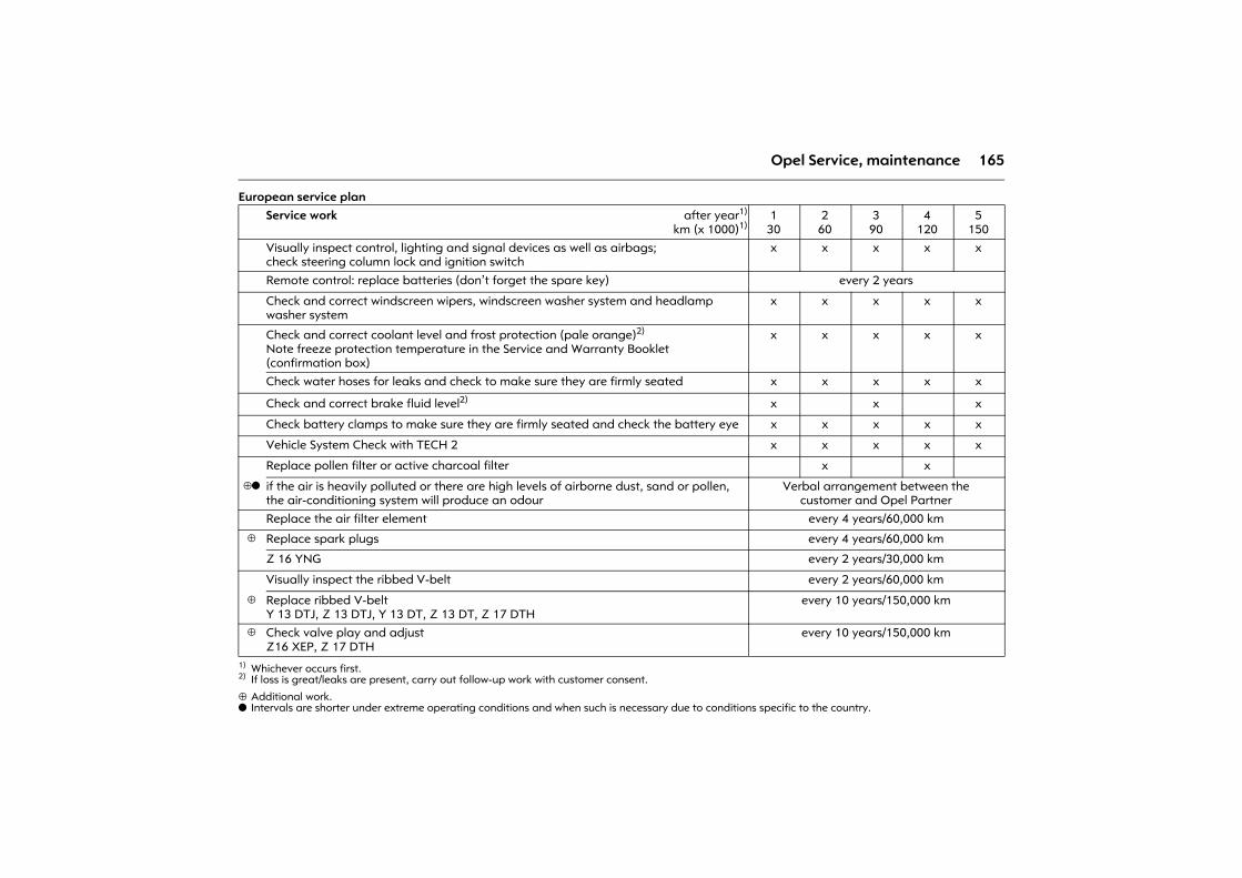
165Opel Service, maintenance
European service plan
⊕ Additional work.o Intervals are shorter under extreme operating conditions and when such is necessary due to conditions specific to the country.
Service work after year1)
km (x 1000)1)
1) Whichever occurs first.
130
260
390
4120
5150
Visually inspect control, lighting and signal devices as well as airbags;check steering column lock and ignition switch
x x x x x
Remote control: replace batteries (don�t forget the spare key) every 2 years
Check and correct windscreen wipers, windscreen washer system and headlamp washer system
x x x x x
Check and correct coolant level and frost protection (pale orange)2)
Note freeze protection temperature in the Service and Warranty Booklet (confirmation box)
2) If loss is great/leaks are present, carry out follow-up work with customer consent.
x x x x x
Check water hoses for leaks and check to make sure they are firmly seated x x x x x
Check and correct brake fluid level2) x x x
Check battery clamps to make sure they are firmly seated and check the battery eye x x x x x
Vehicle System Check with TECH 2 x x x x x
Replace pollen filter or active charcoal filter x x
⊕o if the air is heavily polluted or there are high levels of airborne dust, sand or pollen, the air-conditioning system will produce an odour
Verbal arrangement between the customer and Opel Partner
Replace the air filter element every 4 years/60,000 km
⊕ Replace spark plugs every 4 years/60,000 km
Z 16 YNG every 2 years/30,000 km
Visually inspect the ribbed V-belt every 2 years/60,000 km
⊕ Replace ribbed V-beltY 13 DTJ, Z 13 DTJ, Y 13 DT, Z 13 DT, Z 17 DTH
every 10 years/150,000 km
⊕ Check valve play and adjust Z16 XEP, Z 17 DTH
every 10 years/150,000 km
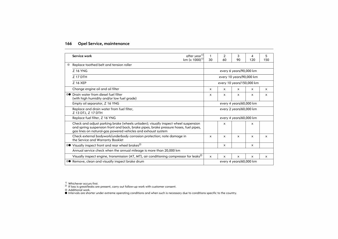
166 Opel Service, maintenance
⊕ Additional work.o Intervals are shorter under extreme operating conditions and when such is necessary due to conditions specific to the country.
Service work after year1)
km (x 1000)1)
1) Whichever occurs first.
130
260
390
4120
5150
⊕ Replace toothed belt and tension roller
Z 16 YNG every 6 years/90,000 km
Z 17 DTH every 10 years/90,000 km
Z 16 XEP every 10 years/150,000 km
Change engine oil and oil filter x x x x x
⊕o Drain water from diesel fuel filter(with high humidity and/or low fuel grade)
x x x x x
Empty oil separator, Z 16 YNG every 4 years/60,000 km
Replace and drain water from fuel filter,Z 13 DTJ, Z 17 DTH
every 2 years/60,000 km
Replace fuel filter, Z 16 YNG every 4 years/60,000 km
Check and adjust parking brake (wheels unladen); visually inspect wheel suspension and spring suspension front and back, brake pipes, brake pressure hoses, fuel pipes, gas lines on natural-gas powered vehicles and exhaust system
x x
Check external bodywork/underbody corrosion protection; note damage in the Service and Warranty Booklet
x x x x x
⊕o Visually inspect front and rear wheel brakes2)
2) If loss is great/leaks are present, carry out follow-up work with customer consent.
x x
Annual service check when the annual mileage is more than 20,000 km
Visually inspect engine, transmission (AT, MT), air conditioning compressor for leaks2) x x x x x⊕o Remove, clean and visually inspect brake drum every 4 years/60,000 km
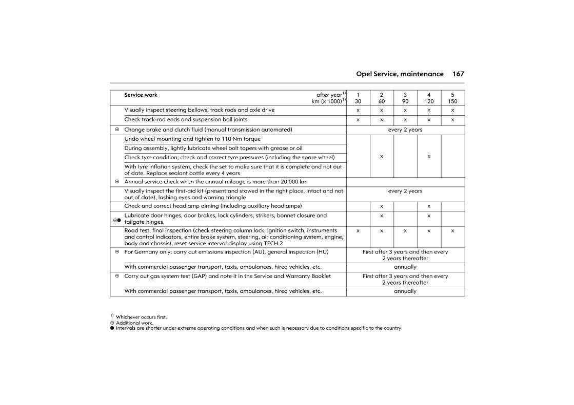
167Opel Service, maintenance
⊕ Additional work.o Intervals are shorter under extreme operating conditions and when such is necessary due to conditions specific to the country.
Service work after year1)
km (x 1000)1)
1) Whichever occurs first.
130
260
390
4120
5150
Visually inspect steering bellows, track rods and axle drive x x x x x
Check track-rod ends and suspension ball joints x x x x x
⊕ Change brake and clutch fluid (manual transmission automated) every 2 years
Undo wheel mounting and tighten to 110 Nm torque
x xDuring assembly, lightly lubricate wheel bolt tapers with grease or oil
Check tyre condition; check and correct tyre pressures (including the spare wheel)
With tyre inflation system, check the set to make sure that it is complete and not out of date. Replace sealant bottle every 4 years
⊕ Annual service check when the annual mileage is more than 20,000 km
Visually inspect the first-aid kit (present and stowed in the right place, intact and not out of date), lashing eyes and warning triangle
every 2 years
Check and correct headlamp aiming (including auxiliary headlamps) x x
⊕oLubricate door hinges, door brakes, lock cylinders, strikers, bonnet closure and tailgate hinges.
x x
Road test, final inspection (check steering column lock, ignition switch, instruments and control indicators, entire brake system, steering, air conditioning system, engine, body and chassis), reset service interval display using TECH 2
x x x x x
⊕ For Germany only: carry out emissions inspection (AU), general inspection (HU) First after 3 years and then every 2 years thereafter
With commercial passenger transport, taxis, ambulances, hired vehicles, etc. annually
⊕ Carry out gas system test (GAP) and note it in the Service and Warranty Booklet First after 3 years and then every 2 years thereafter
With commercial passenger transport, taxis, ambulances, hired vehicles, etc. annually
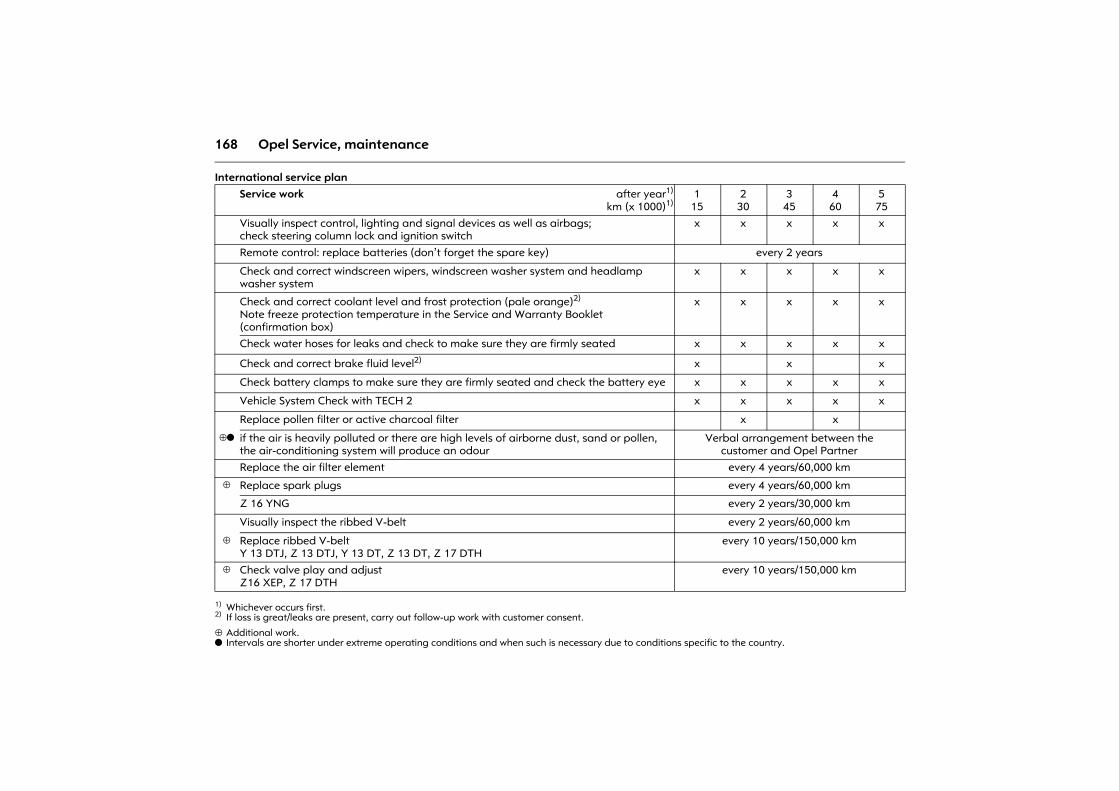
168 Opel Service, maintenance
International service plan
⊕ Additional work.o Intervals are shorter under extreme operating conditions and when such is necessary due to conditions specific to the country.
Service work after year1)
km (x 1000)1)
1) Whichever occurs first.
115
230
345
460
575
Visually inspect control, lighting and signal devices as well as airbags;check steering column lock and ignition switch
x x x x x
Remote control: replace batteries (don�t forget the spare key) every 2 years
Check and correct windscreen wipers, windscreen washer system and headlamp washer system
x x x x x
Check and correct coolant level and frost protection (pale orange)2)
Note freeze protection temperature in the Service and Warranty Booklet (confirmation box)
2) If loss is great/leaks are present, carry out follow-up work with customer consent.
x x x x x
Check water hoses for leaks and check to make sure they are firmly seated x x x x x
Check and correct brake fluid level2) x x x
Check battery clamps to make sure they are firmly seated and check the battery eye x x x x x
Vehicle System Check with TECH 2 x x x x x
Replace pollen filter or active charcoal filter x x
⊕o if the air is heavily polluted or there are high levels of airborne dust, sand or pollen, the air-conditioning system will produce an odour
Verbal arrangement between the customer and Opel Partner
Replace the air filter element every 4 years/60,000 km
⊕ Replace spark plugs every 4 years/60,000 km
Z 16 YNG every 2 years/30,000 km
Visually inspect the ribbed V-belt every 2 years/60,000 km
⊕ Replace ribbed V-beltY 13 DTJ, Z 13 DTJ, Y 13 DT, Z 13 DT, Z 17 DTH
every 10 years/150,000 km
⊕ Check valve play and adjust Z16 XEP, Z 17 DTH
every 10 years/150,000 km
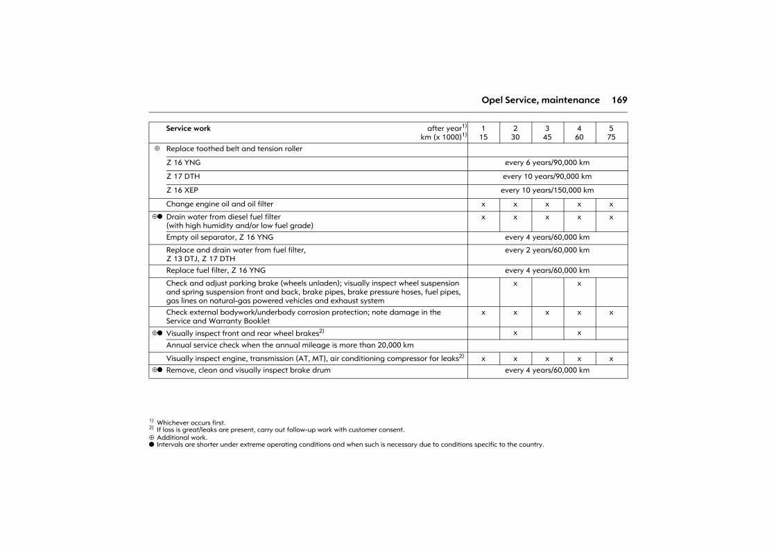
169Opel Service, maintenance
⊕ Additional work.o Intervals are shorter under extreme operating conditions and when such is necessary due to conditions specific to the country.
Service work after year1)
km (x 1000)1)
1) Whichever occurs first.
115
230
345
460
575
⊕ Replace toothed belt and tension roller
Z 16 YNG every 6 years/90,000 km
Z 17 DTH every 10 years/90,000 km
Z 16 XEP every 10 years/150,000 km
Change engine oil and oil filter x x x x x
⊕o Drain water from diesel fuel filter(with high humidity and/or low fuel grade)
x x x x x
Empty oil separator, Z 16 YNG every 4 years/60,000 km
Replace and drain water from fuel filter,Z 13 DTJ, Z 17 DTH
every 2 years/60,000 km
Replace fuel filter, Z 16 YNG every 4 years/60,000 km
Check and adjust parking brake (wheels unladen); visually inspect wheel suspension and spring suspension front and back, brake pipes, brake pressure hoses, fuel pipes, gas lines on natural-gas powered vehicles and exhaust system
x x
Check external bodywork/underbody corrosion protection; note damage in the Service and Warranty Booklet
x x x x x
⊕o Visually inspect front and rear wheel brakes2)
2) If loss is great/leaks are present, carry out follow-up work with customer consent.
x x
Annual service check when the annual mileage is more than 20,000 km
Visually inspect engine, transmission (AT, MT), air conditioning compressor for leaks2) x x x x x⊕o Remove, clean and visually inspect brake drum every 4 years/60,000 km
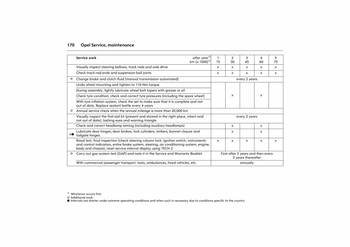
170 Opel Service, maintenance
⊕ Additional work.o Intervals are shorter under extreme operating conditions and when such is necessary due to conditions specific to the country.
Service work after year1)
km (x 1000)1)
1) Whichever occurs first.
115
230
345
460
575
Visually inspect steering bellows, track rods and axle drive x x x x x
Check track-rod ends and suspension ball joints x x x x x
⊕ Change brake and clutch fluid (manual transmission automated) every 2 years
Undo wheel mounting and tighten to 110 Nm torque
x xDuring assembly, lightly lubricate wheel bolt tapers with grease or oil
Check tyre condition; check and correct tyre pressures (including the spare wheel)
With tyre inflation system, check the set to make sure that it is complete and not out of date. Replace sealant bottle every 4 years
⊕ Annual service check when the annual mileage is more than 20,000 km
Visually inspect the first-aid kit (present and stowed in the right place, intact and not out of date), lashing eyes and warning triangle
every 2 years
Check and correct headlamp aiming (including auxiliary headlamps) x x
⊕oLubricate door hinges, door brakes, lock cylinders, strikers, bonnet closure and tailgate hinges.
x x
Road test, final inspection (check steering column lock, ignition switch, instruments and control indicators, entire brake system, steering, air conditioning system, engine, body and chassis), reset service interval display using TECH 2
x x x x x
⊕ Carry out gas system test (GAP) and note it in the Service and Warranty Booklet First after 3 years and then every 2 years thereafter
With commercial passenger transport, taxis, ambulances, hired vehicles, etc. annually
171Opel Service, maintenance
Additional service workAdditional work ⊕Additional work is work which is not required for every service but can be carried out along with a regular service.
Time allowances for such work are not included within the scope of a regular service and must be accounted for separately. However, it is more cost effective to carry out this work as part of a planned service than to have it done separately.
Extreme operating conditions oOperating conditions are considered extreme when one or more of the following occur frequently:
z Cold starts,
z Stop-and-go,
z Caravan/trailer towing,
z Driving on inclines and/or in high altitudes,
z Poor road conditions,
z Sand and dust,
z Extreme temperature fluctuations.
Police vehicles, taxis and driving school vehicles are also classified as operating under extreme conditions.
When operating conditions are extreme, it may be necessary to have certain service work carried out more frequently than the planned service intervals.
We recommend obtaining technical advice for the service requirements of your vehicle based on the special conditions of use.
Recommended fluids and lubricants Only use products which have been tested and approved. Damage caused by using non-approved operating materials is not covered by the warranty.
9 Warning
Fuels are dangerous and require appropriate care when handling. If swallowed, immediately call a doctor. Do not inhale fumes and avoid contact with the skin. Keep out of the reach of children. Fuels must not be allowed to contaminate wastewater, groundwater or soils. Dispose of empty containers properly. Always keep in mind that fuels are hazardous to health.
172 Opel Service, maintenance
Engine oilEngine oil is identified by its grade and viscosity. When choosing which engine oil to use, grade is more important than viscosity.
Engine oil grade for the European service
Opel Engine oil complies with the classifications GM-LL-A-025 and GM-LL-B-025 and is therefore suitable for both petrol and diesel engines.
Engine oil grade for the International service plan
Topping up engine oilOil from different manufacturers and of different brands can be mixed providing they meet the specified engine oil criteria (grade and viscosity).
Not every engine oil available on the market satisfies the quality requirements, so always check whether the required specifications and classifications are written on the container.
If an engine oil of the required grade is not available, a maximum of 1 litre of ACEA A3/B4 or A3/B3 oil can be used (just once between oil changes). The viscosity must comply with the requirements.
Using category ACEA A1/B1 and A5/B5 engine oil is expressly forbidden because it can cause long-term damage to the engine under certain operating conditions.
Engine oil additivesThe use of engine oil additives can cause damage and void the warranty.
Engine oil viscosityOnly use engine oils of viscosity 0W-30, 0W-40, 5W-30 or 5W-40.
The SAE viscosity classification defines the fluidity of the oil: the oil is more viscous when cold than when hot.
Multigrade oil is indicated by two numbers. The first number followed by a W gives the viscosity at low temperature and the second number gives the viscosity at high temperature.
GM-LL-A-025: Petrol enginesGM-LL-B-025: Diesel engines
GM General Motors EuropeLL LonglifeA or B Information on engine oil
grade025 Validity code
ACEA-A3: Petrol engines
ACEA-B4: Diesel engines without diesel particle filter
ACEA-C3: Diesel engines with diesel particle filter
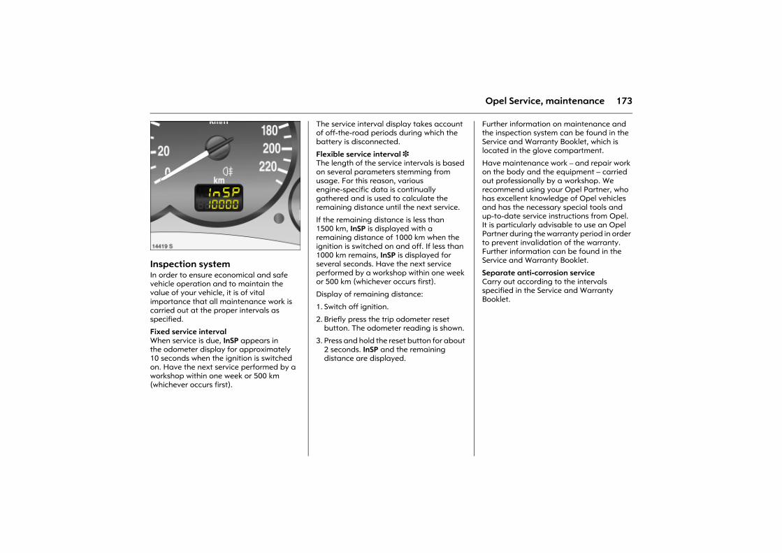
173Opel Service, maintenance
Picture no: 14419s.tifInspection systemIn order to ensure economical and safe vehicle operation and to maintain the value of your vehicle, it is of vital importance that all maintenance work is carried out at the proper intervals as specified.
Fixed service interval When service is due, InSP appears in the odometer display for approximately 10 seconds when the ignition is switched on. Have the next service performed by a workshop within one week or 500 km (whichever occurs first).
The service interval display takes account of off-the-road periods during which the battery is disconnected.
Flexible service interval 3 The length of the service intervals is based on several parameters stemming from usage. For this reason, various engine-specific data is continually gathered and is used to calculate the remaining distance until the next service.
If the remaining distance is less than 1500 km, InSP is displayed with a remaining distance of 1000 km when the ignition is switched on and off. If less than 1000 km remains, InSP is displayed for several seconds. Have the next service performed by a workshop within one week or 500 km (whichever occurs first).
Display of remaining distance:
1. Switch off ignition.
2. Briefly press the trip odometer reset button. The odometer reading is shown.
3. Press and hold the reset button for about 2 seconds. InSP and the remaining distance are displayed.
Further information on maintenance and the inspection system can be found in the Service and Warranty Booklet, which is located in the glove compartment.
Have maintenance work � and repair work on the body and the equipment � carried out professionally by a workshop. We recommend using your Opel Partner, who has excellent knowledge of Opel vehicles and has the necessary special tools and up-to-date service instructions from Opel. It is particularly advisable to use an Opel Partner during the warranty period in order to prevent invalidation of the warranty. Further information can be found in the Service and Warranty Booklet.
Separate anti-corrosion service Carry out according to the intervals specified in the Service and Warranty Booklet.
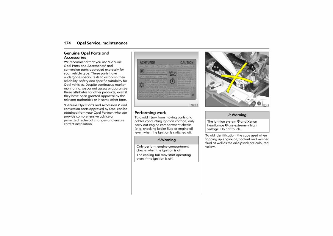
174 Opel Service, maintenance
Genuine Opel Parts and Accessories We recommend that you use "Genuine Opel Parts and Accessories" and conversion parts approved expressly for your vehicle type. These parts have undergone special tests to establish their reliability, safety and specific suitability for Opel vehicles. Despite continuous market monitoring, we cannot assess or guarantee these attributes for other products, even if they have been granted approval by the relevant authorities or in some other form.
"Genuine Opel Parts and Accessories" and conversion parts approved by Opel can be obtained from your Opel Partner, who can provide comprehensive advice on permitted technical changes and ensure correct installation.
Picture no: 17922s.tifPerforming work To avoid injury from moving parts and cables conducting ignition voltage, only carry out engine compartment checks (e. g. checking brake fluid or engine oil level) when the ignition is switched off.
Picture no: 11671s.tif
To aid identification, the caps used when topping up engine oil, coolant and washer fluid as well as the oil dipstick are coloured yellow.
9 Warning
Only perform engine compartment checks when the ignition is off. The cooling fan may start operating even if the ignition is off.
9 Warning
The ignition system 3 and Xenon headlamps 3 use extremely high voltage. Do not touch.
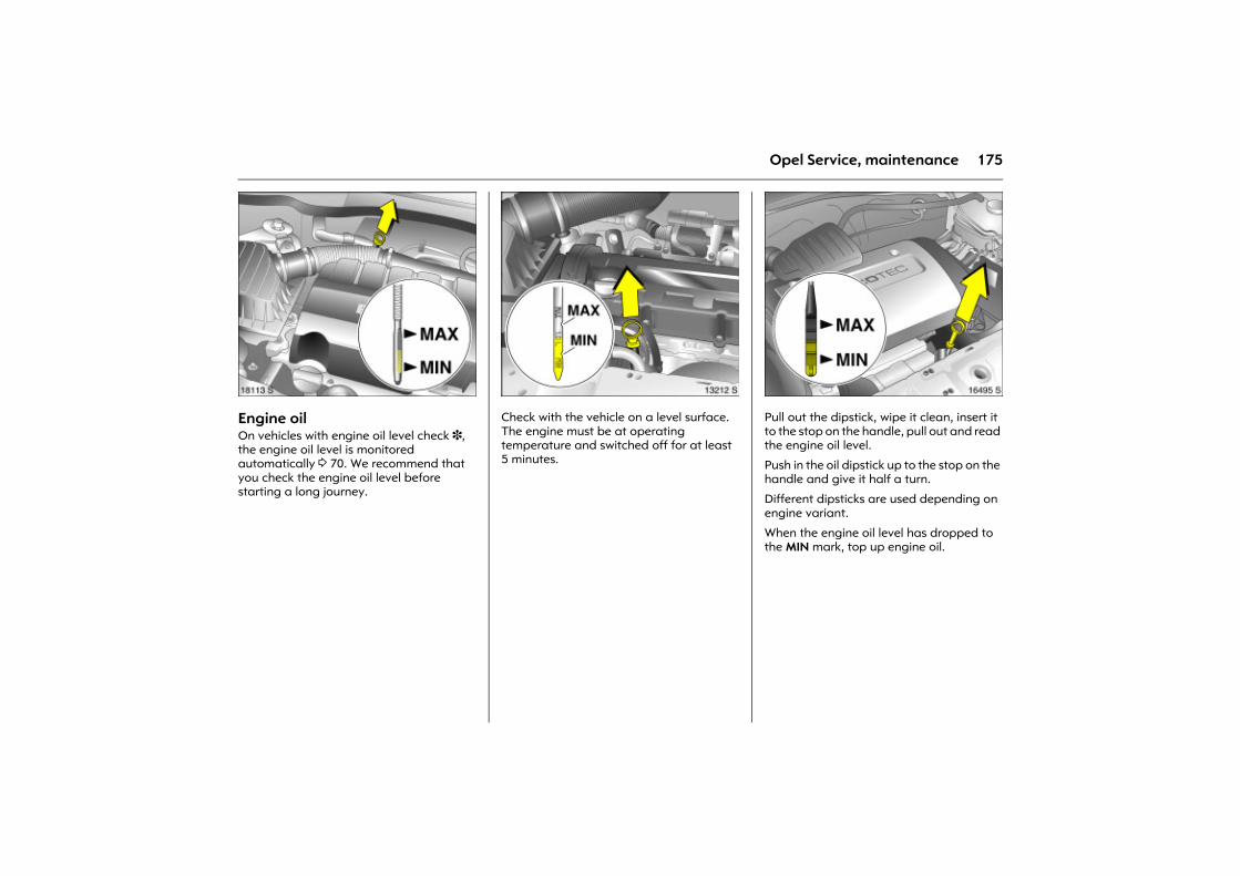
175Opel Service, maintenance
Picture no: 18113s.tifEngine oil On vehicles with engine oil level check 3, the engine oil level is monitored automatically 3 70. We recommend that you check the engine oil level before starting a long journey.
Picture no: 13212s.tifCheck with the vehicle on a level surface. The engine must be at operating temperature and switched off for at least 5 minutes.
Picture no: 16495s.tifPull out the dipstick, wipe it clean, insert it to the stop on the handle, pull out and read the engine oil level.
Push in the oil dipstick up to the stop on the handle and give it half a turn.
Different dipsticks are used depending on engine variant.
When the engine oil level has dropped to the MIN mark, top up engine oil.
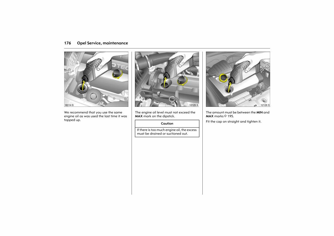
176 Opel Service, maintenance
Picture no: 18114s.tifWe recommend that you use the same engine oil as was used the last time it was topped up.
Picture no: 12125s.tifThe engine oil level must not exceed the MAX mark on the dipstick.
Picture no: 12126s.tifThe amount must be between the MIN and MAX marks 3 195.
Fit the cap on straight and tighten it. Caution
If there is too much engine oil, the excess must be drained or suctioned out.
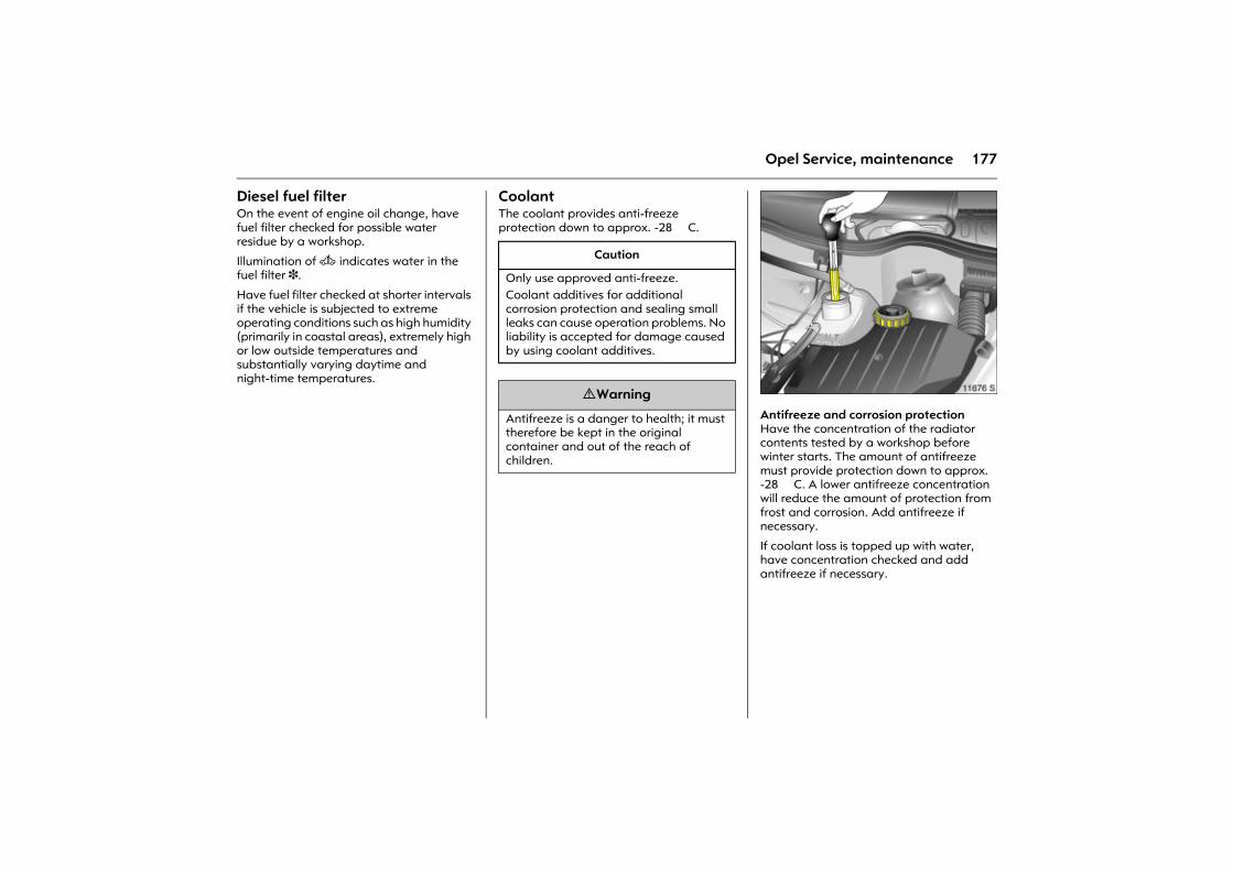
177Opel Service, maintenance
Diesel fuel filter On the event of engine oil change, have fuel filter checked for possible water residue by a workshop.
Illumination of A indicates water in the fuel filter 3.
Have fuel filter checked at shorter intervals if the vehicle is subjected to extreme operating conditions such as high humidity (primarily in coastal areas), extremely high or low outside temperatures and substantially varying daytime and night-time temperatures.
Coolant The coolant provides anti-freeze protection down to approx. -28 �C.
.
Picture no: 11676s.tifAntifreeze and corrosion protectionHave the concentration of the radiator contents tested by a workshop before winter starts. The amount of antifreeze must provide protection down to approx. -28 �C. A lower antifreeze concentration will reduce the amount of protection from frost and corrosion. Add antifreeze if necessary.
If coolant loss is topped up with water, have concentration checked and add antifreeze if necessary.
Caution
Only use approved anti-freeze. Coolant additives for additional corrosion protection and sealing small leaks can cause operation problems. No liability is accepted for damage caused by using coolant additives.
9 Warning
Antifreeze is a danger to health; it must therefore be kept in the original container and out of the reach of children.
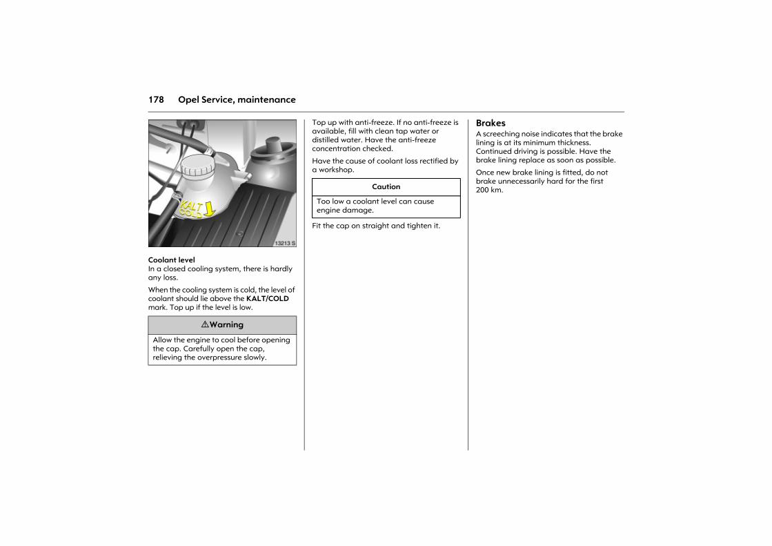
178 Opel Service, maintenance
Picture no: 13213s.tifCoolant level In a closed cooling system, there is hardly any loss.
When the cooling system is cold, the level of coolant should lie above the KALT/COLD mark. Top up if the level is low.
Top up with anti-freeze. If no anti-freeze is available, fill with clean tap water or distilled water. Have the anti-freeze concentration checked.
Have the cause of coolant loss rectified by a workshop.
Fit the cap on straight and tighten it.
Brakes A screeching noise indicates that the brake lining is at its minimum thickness. Continued driving is possible. Have the brake lining replace as soon as possible.
Once new brake lining is fitted, do not brake unnecessarily hard for the first 200 km.
9 Warning
Allow the engine to cool before opening the cap. Carefully open the cap, relieving the overpressure slowly.
Caution
Too low a coolant level can cause engine damage.
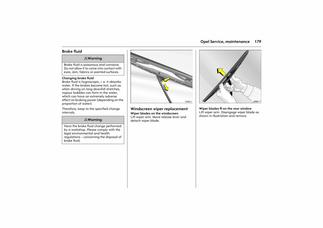
179Opel Service, maintenance
Brake fluid
Changing brake fluid Brake fluid is hygroscopic, i. e. it absorbs water. If the brakes become hot, such as when driving on long downhill stretches, vapour bubbles can form in the water, which can have an extremely adverse effect on braking power (depending on the proportion of water).
Therefore, keep to the specified change intervals.
Picture no: 13328j.tifWindscreen wiper replacement Wiper blades on the windscreen Lift wiper arm. Move release lever and detach wiper blade.
Picture no: 9392t.tifWiper blades 3 on the rear window Lift wiper arm. Disengage wiper blade as shown in illustration and remove.
9 Warning
Brake fluid is poisonous and corrosive. Do not allow it to come into contact with eyes, skin, fabrics or painted surfaces.
9 Warning
Have the brake fluid change performed by a workshop. Please comply with the legal environmental and health regulations � concerning the disposal of brake fluid.
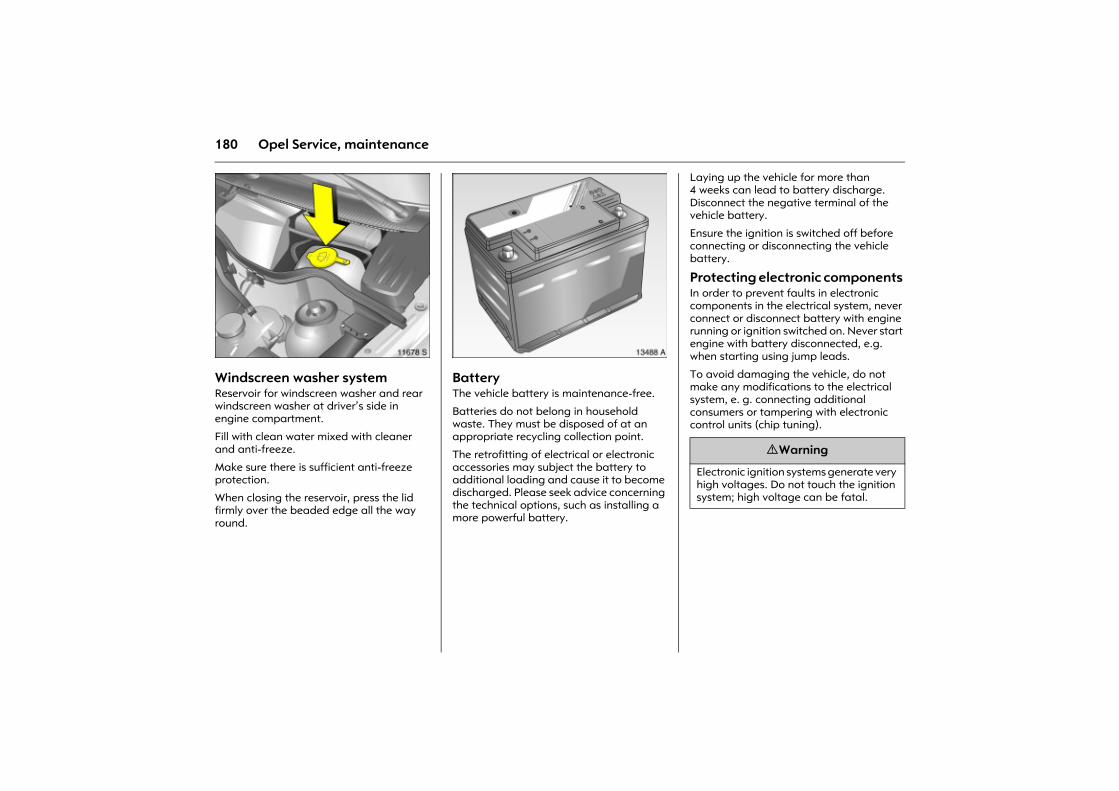
180 Opel Service, maintenance
Picture no: 11678s.tifWindscreen washer system Reservoir for windscreen washer and rear windscreen washer at driver�s side in engine compartment.
Fill with clean water mixed with cleaner and anti-freeze.
Make sure there is sufficient anti-freeze protection.
When closing the reservoir, press the lid firmly over the beaded edge all the way round.
Picture no: 13488a.tifBattery The vehicle battery is maintenance-free.
Batteries do not belong in household waste. They must be disposed of at an appropriate recycling collection point.
The retrofitting of electrical or electronic accessories may subject the battery to additional loading and cause it to become discharged. Please seek advice concerning the technical options, such as installing a more powerful battery.
Laying up the vehicle for more than 4 weeks can lead to battery discharge. Disconnect the negative terminal of the vehicle battery.
Ensure the ignition is switched off before connecting or disconnecting the vehicle battery.
Protecting electronic components In order to prevent faults in electronic components in the electrical system, never connect or disconnect battery with engine running or ignition switched on. Never start engine with battery disconnected, e.g. when starting using jump leads.
To avoid damaging the vehicle, do not make any modifications to the electrical system, e. g. connecting additional consumers or tampering with electronic control units (chip tuning).
9 Warning
Electronic ignition systems generate very high voltages. Do not touch the ignition system; high voltage can be fatal.
181Opel Service, maintenance
Laying the vehicle up for a long period of time If the vehicle is to be laid up for several months, the following work should be undertaken to prevent damage.
z Wash and wax the vehicle 3 161.
z Have the wax in the engine compartment and underbody checked.
z Clean and preserve rubber seals.
z Change engine oil.
z Check anti-freeze and corrosion protection 3 177.
z Check the coolant level; top up anti-freeze if necessary 3 178.
z Drain the windscreen washer system.
z Increase tyre pressure to the value specified for full load 3 121, 3 191.
z Park the vehicle in dry and well-ventilated place. With manual transmission select first or reverse gear; with manual transmission automated 3 move the selector lever to the centre position before switching the ignition off. Use chocks or the like to prevent the vehicle from rolling.
z Do not apply hand brake.
z Disconnect the clamp from the negative terminal of the vehicle battery.
Putting the vehicle back into servicePerform the following work before recommissioning the vehicle:
z Connect the clamp to the negative terminal of the vehicle battery.
z Check tyre pressure 3 121, 3 191.
z Top up the windscreen washer system 3 180.
z Check engine oil level 3 175.
z Check coolant level 3 178.
z Fit the number plate if necessary.
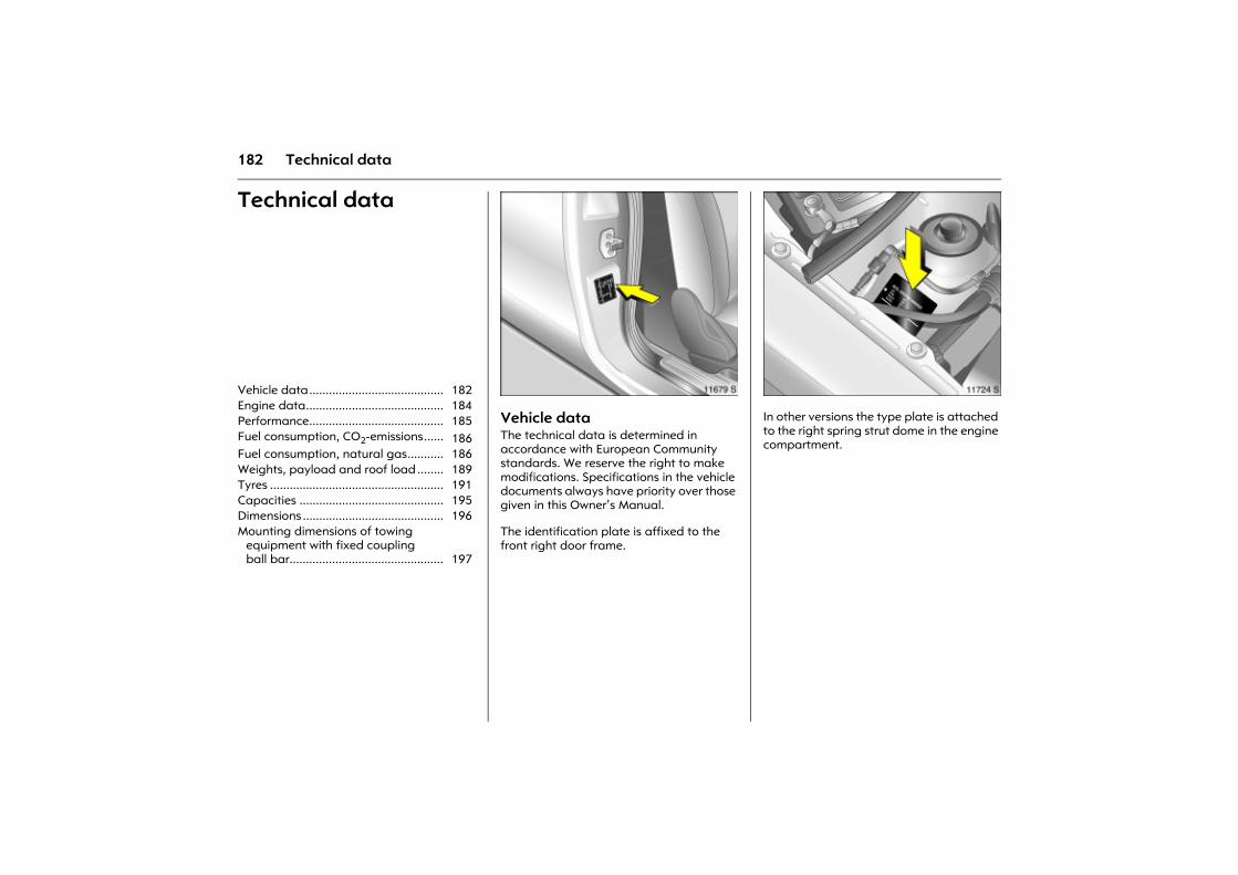
182 Technical data
Technical data
Picture no: 11679s.tifVehicle data The technical data is determined in accordance with European Community standards. We reserve the right to make modifications. Specifications in the vehicle documents always have priority over those given in this Owner�s Manual.
The identification plate is affixed to the front right door frame.
Picture no: 11724s.tifIn other versions the type plate is attached to the right spring strut dome in the engine compartment.
Vehicle data......................................... 182 Engine data.......................................... 184 Performance......................................... 185 Fuel consumption, CO2-emissions...... 186 Fuel consumption, natural gas........... 186 Weights, payload and roof load ........ 189 Tyres ..................................................... 191 Capacities ............................................ 195 Dimensions ........................................... 196 Mounting dimensions of towing
equipment with fixed coupling ball bar............................................... 197
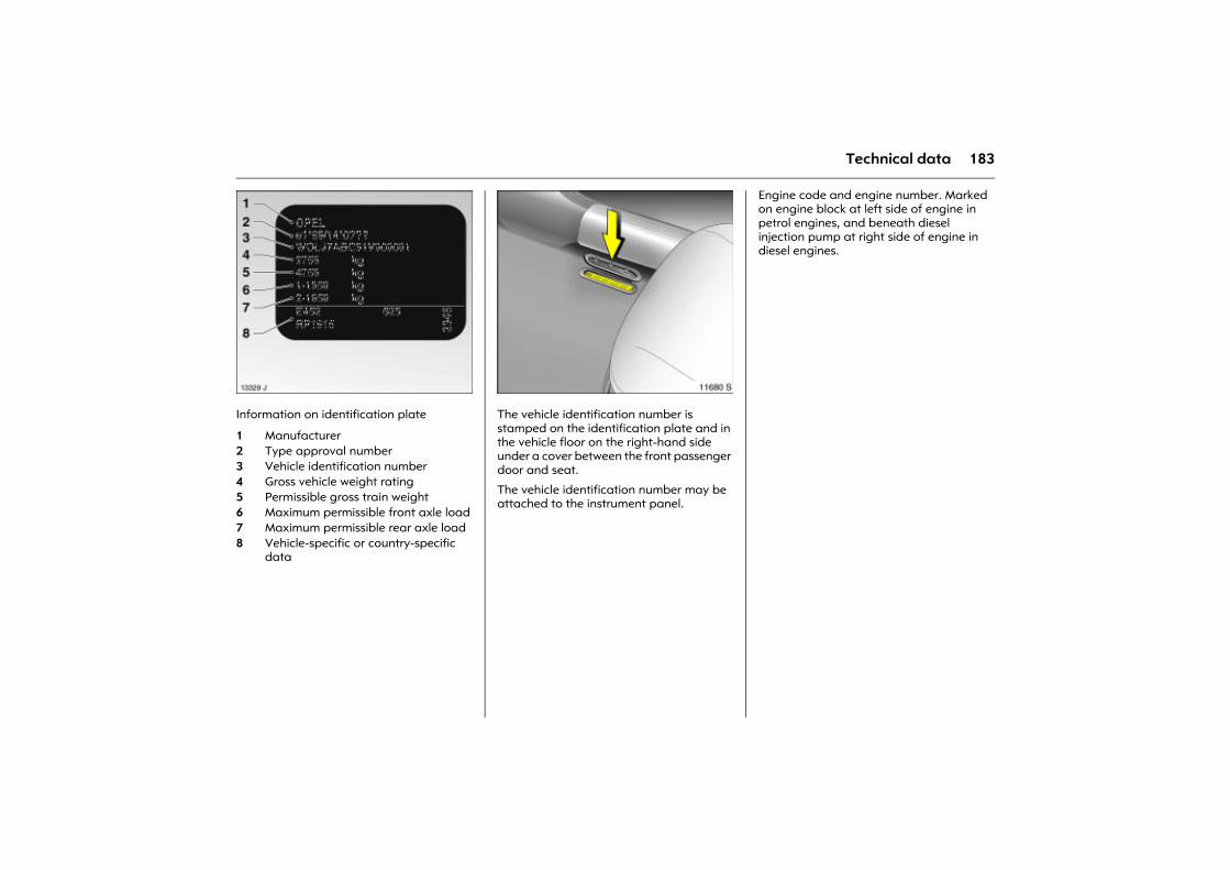
183Technical data
Picture no: 13329j.tifInformation on identification plate
Picture no: 11680s.tifThe vehicle identification number is stamped on the identification plate and in the vehicle floor on the right-hand side under a cover between the front passenger door and seat.
The vehicle identification number may be attached to the instrument panel.
Engine code and engine number. Marked on engine block at left side of engine in petrol engines, and beneath diesel injection pump at right side of engine in diesel engines.
1 Manufacturer2 Type approval number3 Vehicle identification number4 Gross vehicle weight rating5 Permissible gross train weight6 Maximum permissible front axle load7 Maximum permissible rear axle load8 Vehicle-specific or country-specific
data
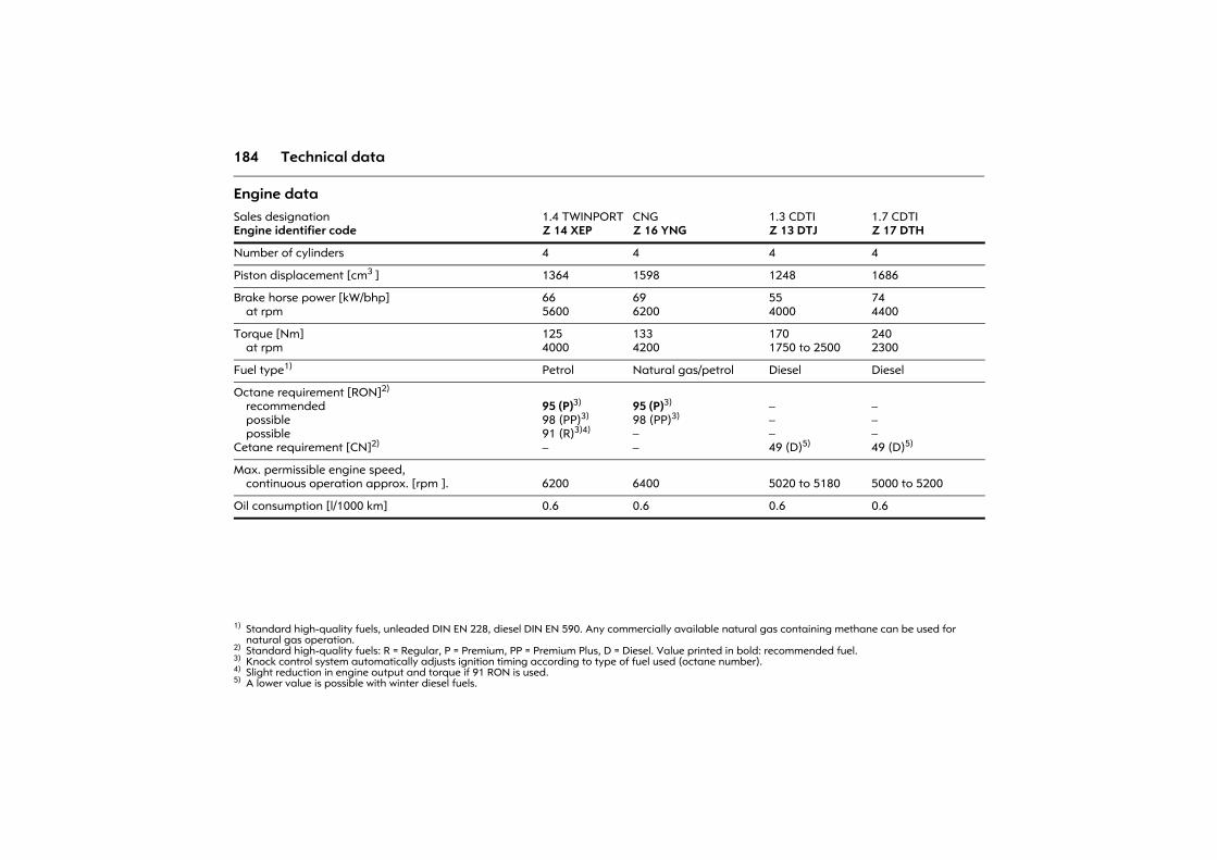
184 Technical data
Engine data Sales designationEngine identifier code
1.4 TWINPORTZ 14 XEP
CNGZ 16 YNG
1.3 CDTIZ 13 DTJ
1.7 CDTIZ 17 DTH
Number of cylinders 4 4 4 4
Piston displacement [cm3 ] 1364 1598 1248 1686
Brake horse power [kW/bhp]at rpm
665600
696200
554000
744400
Torque [Nm]at rpm
1254000
1334200
1701750 to 2500
2402300
Fuel type1)
1) Standard high-quality fuels, unleaded DIN EN 228, diesel DIN EN 590. Any commercially available natural gas containing methane can be used for natural gas operation.
Petrol Natural gas/petrol Diesel Diesel
Octane requirement [RON]2)
recommendedpossiblepossible
Cetane requirement [CN]2)
2) Standard high-quality fuels: R = Regular, P = Premium, PP = Premium Plus, D = Diesel. Value printed in bold: recommended fuel.
95 (P)3)
98 (PP)3)
91 (R)3)4)
�
3) Knock control system automatically adjusts ignition timing according to type of fuel used (octane number). 4) Slight reduction in engine output and torque if 91 RON is used.
95 (P)3)
98 (PP)3)
��
���49 (D)5)
5) A lower value is possible with winter diesel fuels.
���49 (D)5)
Max. permissible engine speed,continuous operation approx. [rpm ]. 6200 6400 5020 to 5180 5000 to 5200
Oil consumption [l/1000 km] 0.6 0.6 0.6 0.6
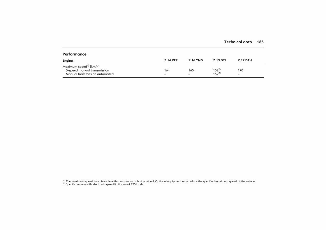
185Technical data
Performance
Engine Z 14 XEP Z 16 YNG Z 13 DTJ Z 17 DTH
Maximum speed1) [km/h]5-speed manual transmissionManual transmission automated
1) The maximum speed is achievable with a maximum of half payload. Optional equipment may reduce the specified maximum speed of the vehicle.
164�
165�
1522)
1522)
2) Specific version with electronic speed limitation at 125 km/h.
170�
186 Technical data
Fuel consumption, CO2-emissions Directive 80/1268/EEC (last changed by 2004/3/EC) has applied for the measurement of fuel consumption since 1996.
The directive is oriented to actual driving practices: Urban driving is rated at approx. 1/3 and off-road driving with
approx. 2/3 (urban and extra-urban consumption). Cold starts and acceleration phases are also taken into consideration.
The specification of CO2 emission is also a constituent of the directive.
The figures given must not be taken as a guarantee for the actual fuel consumption of a particular vehicle.
All values stem from the EU base model with standard equipment.
The calculation of fuel consumption as specified by directive 2004/3/EC takes account of the vehicle�s kerb weight, ascertained in accordance with the said regulation. Optional extras may result in slightly higher fuel consumption and CO2 emission levels than those quoted.
Saving Fuel, Protecting the Environment 3 108.
Fuel consumption, natural gasThe data on fuel consumption has been ascertained with reference fuel G20 (methane content 99 - 100 mol%) under prescribed driving conditions (see previous columns). The fuel consumption values will deviate from those specified if natural gas with a lower methane content is used.
All values stem from the EU base model with standard equipment. The consumption calculated according to the 1999/100/EC directive takes into consideration the kerb weight laid down in agreement with this regulation. Additional equipment as well as the gas condition, filling station pressure, mode of driving and the road and traffic conditions can lead to higher consumptions and CO2 values than those specified.
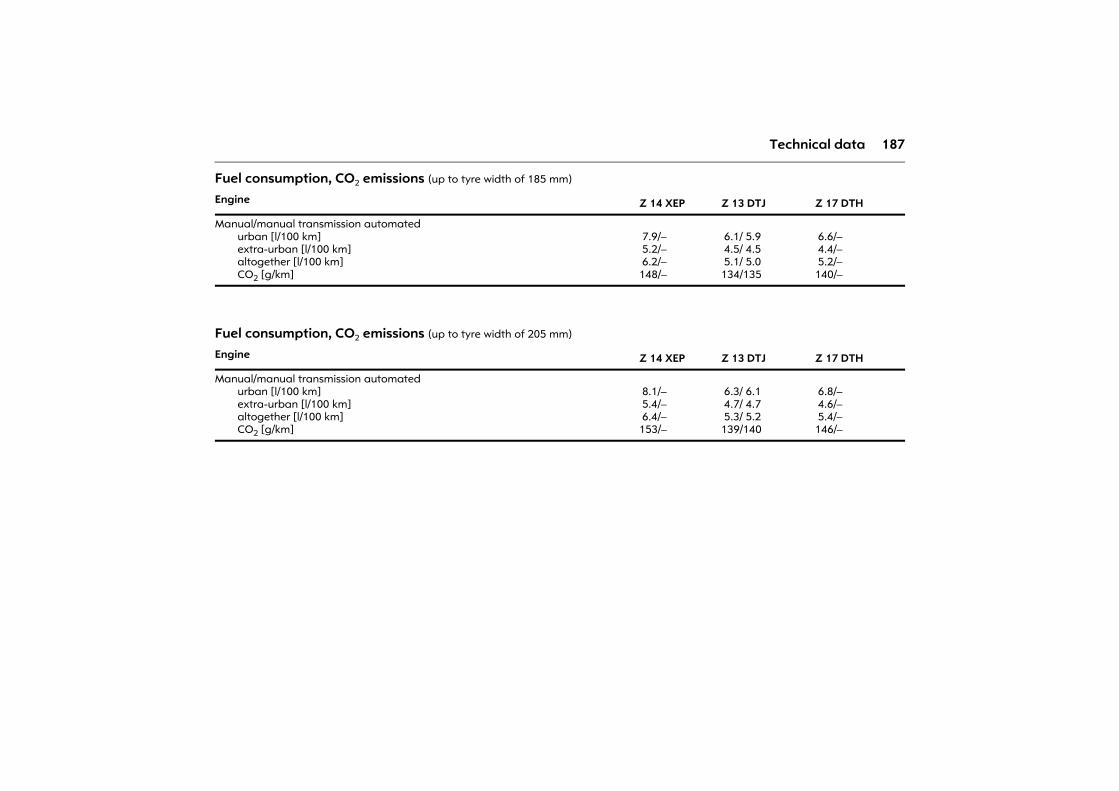
187Technical data
Fuel consumption, CO2 emissions (up to tyre width of 185 mm)
Fuel consumption, CO2 emissions (up to tyre width of 205 mm)
Engine Z 14 XEP Z 13 DTJ Z 17 DTH
Manual/manual transmission automatedurban [l/100 km]extra-urban [l/100 km]altogether [l/100 km]CO2 [g/km]
7.9/� 5.2/� 6.2/�148/�
6.1/ 5.9 4.5/ 4.5 5.1/ 5.0134/135
6.6/� 4.4/� 5.2/�140/�
Engine Z 14 XEP Z 13 DTJ Z 17 DTH
Manual/manual transmission automatedurban [l/100 km]extra-urban [l/100 km]altogether [l/100 km]CO2 [g/km]
8.1/� 5.4/� 6.4/�153/�
6.3/ 6.1 4.7/ 4.7 5.3/ 5.2139/140
6.8/� 4.6/� 5.4/�146/�
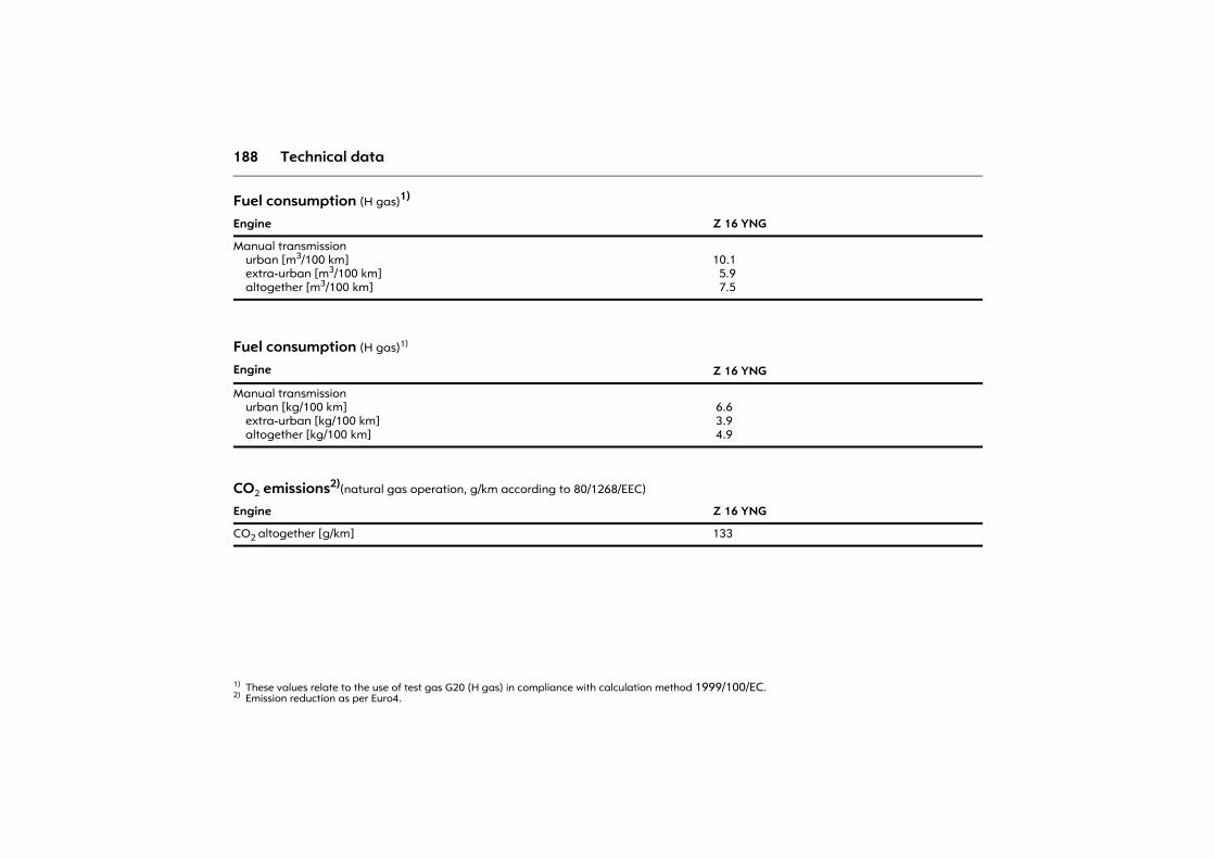
188 Technical data
Fuel consumption (H gas)1)
1) These values relate to the use of test gas G20 (H gas) in compliance with calculation method 1999/100/EC.
Engine Z 16 YNG
Manual transmission urban [m3/100 km] extra-urban [m3/100 km] altogether [m3/100 km]
10.1 5.9 7.5
Fuel consumption (H gas)1)
Engine Z 16 YNG
Manual transmission urban [kg/100 km] extra-urban [kg/100 km] altogether [kg/100 km]
6.6 3.9 4.9
CO2 emissions2)(natural gas operation, g/km according to 80/1268/EEC)
2) Emission reduction as per Euro4.
Engine Z 16 YNG
CO2 altogether [g/km] 133
189Technical data
Weights, payload and roof load The payload is the difference between the permitted gross vehicle weight (see identification plate 3 182) and the EC kerb weight.
To calculate the kerb weight, enter the data for your vehicle below:
is the EC kerb weight.
Optional equipment and accessories increase the kerb weight, which means that the payload will also change slightly.
Note the weights given in the vehicle documents and the identification plate.
The combined total of front and rear axle loads must not exceed the permissible gross vehicle weight. For example, if the front axle is bearing its maximum permissible load, the rear axle can only bear a load that is equal to the gross vehicle weight minus the front axle load.
The permissible axle loads must not be exceeded.
See the identification plate or vehicle documents for permissible axle loads.
Caravan/trailer towing 3 126.
Roof loadThe permissible roof load is 100 kg. The roof load consists of the weight of the roof rack plus the load carried.
Driving hints 3 106. Roof rack 3 125.
z Kerb weight from Table 1 3 190 +.............. kg
z Weight of heavy accessories from Table 2 3 190 +.............. kg
Total =.............. kg
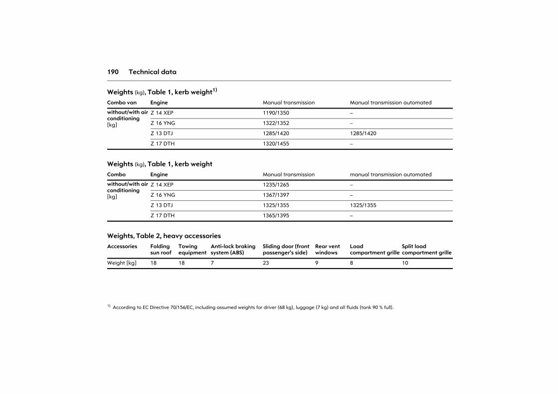
190 Technical data
Weights (kg), Table 1, kerb weight1)
1) According to EC Directive 70/156/EC, including assumed weights for driver (68 kg), luggage (7 kg) and all fluids (tank 90 % full).
Combo van Engine Manual transmission Manual transmission automated
without/with air conditioning [kg]
Z 14 XEP 1190/1350 �
Z 16 YNG 1322/1352 �
Z 13 DTJ 1285/1420 1285/1420
Z 17 DTH 1320/1455 �
Weights (kg), Table 1, kerb weightCombo Engine Manual transmission manual transmission automated
without/with air conditioning [kg]
Z 14 XEP 1235/1265 �
Z 16 YNG 1367/1397 �
Z 13 DTJ 1325/1355 1325/1355
Z 17 DTH 1365/1395 �
Weights, Table 2, heavy accessoriesAccessories Folding
sun roofTowing equipment
Anti-lock brakingsystem (ABS)
Sliding door (front passenger�s side)
Rear ventwindows
Load compartment grille
Split loadcompartment grille
Weight [kg] 18 18 7 23 9 8 10
191Technical data
Tyres Not all tyres available on the market currently meet the structural requirements. We recommend that you consult an Opel Partner concerning suitable tyre makes.
These tyres have undergone special tests to establish their reliability, safety and specific suitability for Opel vehicles. Despite continuous market monitoring, we are unable to assess these attributes for other tyres, even if they have been granted approval by the relevant authorities or in some other form.
Further information 3 121.
Winter tyres 3 Tyre sizes 185/60 R 15, 185/65 R 15, 195/45 R 16 and 195/50 R 16 are not permitted for winter driving.
Exception: Tyres of size 185/60 R 15 may be used as winter tyres on the Combo Tramp/Arizona.
If winter tyres are in use, the spare wheel may still be fitted with a summer tyre. Use of the spare wheel may alter vehicle handling. Obtain a replacement for the faulty tyre as soon as possible, and have the wheel balanced and fitted to the vehicle.
Further information 3 124.
Tyre chains 3 Tyre chains may be used on the front wheels only.
We recommend the use of tyre chains with a fine mesh that add no more than 10 mm to the running surface and the insides of the tyres (including chain lock).
Tyre chains are not permitted on the spare wheel and tyres sizes 185/60 R 15, 185/65 R 15, 195/45 R 16 and 195/50 R 16.
Exception: Tyre chains on tyres of size 185/60 R 15 are permitted on Combo Tramp/Arizona.
Tyre chains are generally permitted on tyres of size 185/55 R 15.
Further information 3 125.
Wheels Wheel bolt tightening torque: 110 Nm.
Spare wheel 3 Depending on the version, the spare wheel is designed for use as a temporary spare wheel 3: the handling of the vehicle may change if the spare wheel is used. Replace a defective tyre as soon as possible, balance the wheel and fit it to vehicle. Pay attention to notes on this page and on 3 125, 3 135.
On vehicles with alloy wheels 3 the spare wheel may have a steel rim.
The spare wheel can be fitted with a smaller tyre1) and a smaller rim than the wheels fitted on the vehicle.
Tyre pressure (overpressure)The specified tyre pressure are valid for cold tyres. The increased tyre pressure resulting from extensive driving must not be reduced. The tyre pressure specified on the following pages apply to both summer and winter tyres.
The spare wheel must always be filled with the tyre pressure for a full load - see tables on following pages.
Temporary spare wheel tyre pressure 3 � see tables on the following pages.
Further information 3 121 to 3 125.
1) Country-specific version: The spare wheel is only permitted for use as a temporary spare.
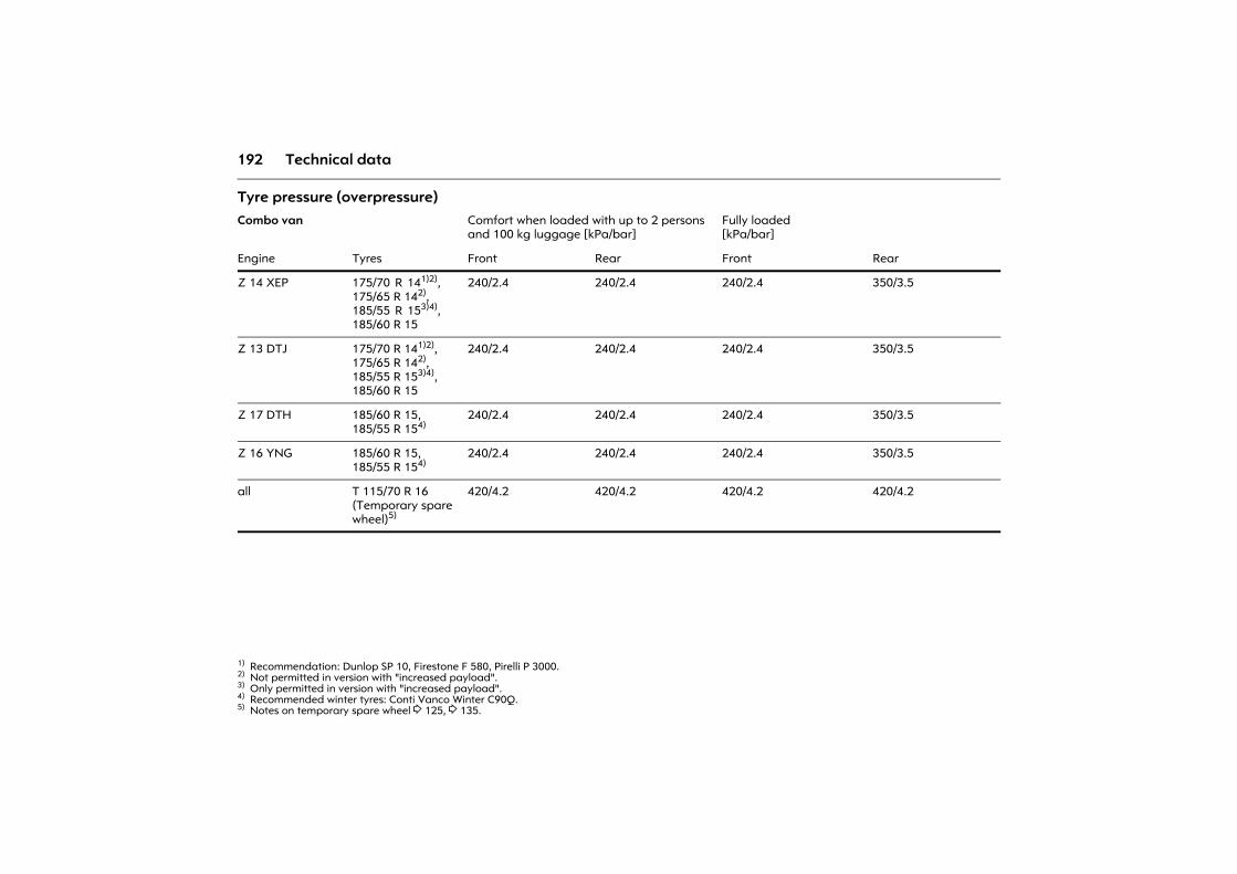
192 Technical data
Tyre pressure (overpressure) Combo van Comfort when loaded with up to 2 persons
and 100 kg luggage [kPa/bar]Fully loaded[kPa/bar]
Engine Tyres Front Rear Front Rear
Z 14 XEP 175/70 R 141)2),175/65 R 142),185/55 R 153)4),185/60 R 15
1) Recommendation: Dunlop SP 10, Firestone F 580, Pirelli P 3000. 2) Not permitted in version with "increased payload".3) Only permitted in version with "increased payload".4) Recommended winter tyres: Conti Vanco Winter C90Q.
240/2.4 240/2.4 240/2.4 350/3.5
Z 13 DTJ 175/70 R 141)2),175/65 R 142),185/55 R 153)4),185/60 R 15
240/2.4 240/2.4 240/2.4 350/3.5
Z 17 DTH 185/60 R 15,185/55 R 154)
240/2.4 240/2.4 240/2.4 350/3.5
Z 16 YNG 185/60 R 15,185/55 R 154)
240/2.4 240/2.4 240/2.4 350/3.5
all T 115/70 R 16(Temporary spare wheel)5)
5) Notes on temporary spare wheel 3 125, 3 135.
420/4.2 420/4.2 420/4.2 420/4.2
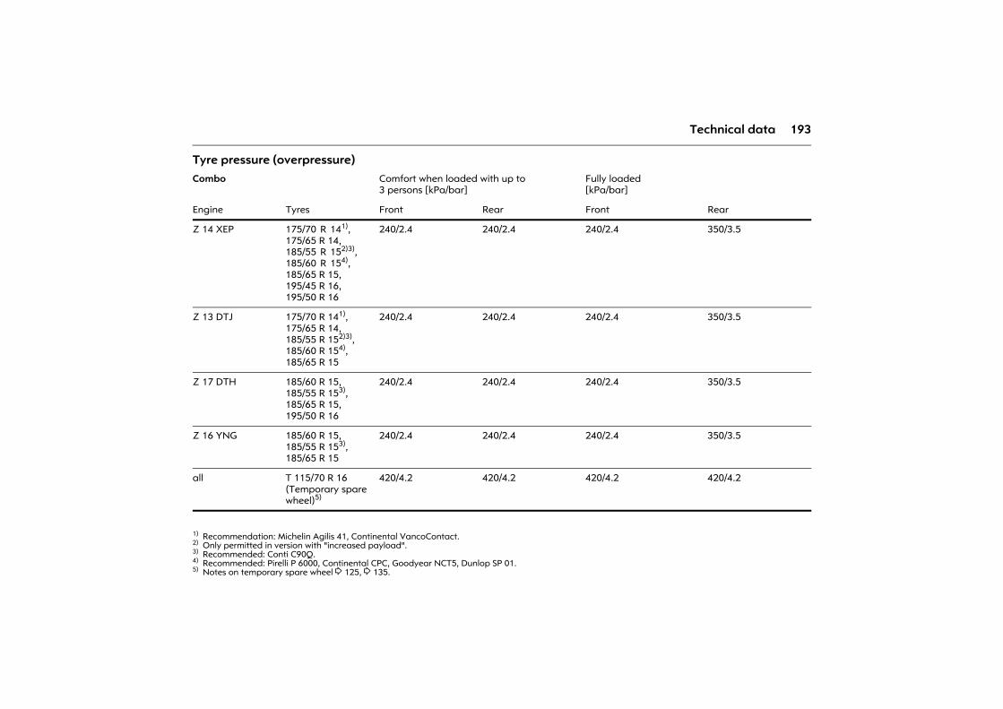
193Technical data
Tyre pressure (overpressure) Combo Comfort when loaded with up to
3 persons [kPa/bar]Fully loaded[kPa/bar]
Engine Tyres Front Rear Front Rear
Z 14 XEP 175/70 R 141),175/65 R 14,185/55 R 152)3),185/60 R 154),185/65 R 15,195/45 R 16,195/50 R 16
1) Recommendation: Michelin Agilis 41, Continental VancoContact. 2) Only permitted in version with "increased payload".3) Recommended: Conti C90Q.4) Recommended: Pirelli P 6000, Continental CPC, Goodyear NCT5, Dunlop SP 01.
240/2.4 240/2.4 240/2.4 350/3.5
Z 13 DTJ 175/70 R 141),175/65 R 14,185/55 R 152)3),185/60 R 154),185/65 R 15
240/2.4 240/2.4 240/2.4 350/3.5
Z 17 DTH 185/60 R 15,185/55 R 153),185/65 R 15,195/50 R 16
240/2.4 240/2.4 240/2.4 350/3.5
Z 16 YNG 185/60 R 15,185/55 R 153),185/65 R 15
240/2.4 240/2.4 240/2.4 350/3.5
all T 115/70 R 16(Temporary spare wheel)5)
5) Notes on temporary spare wheel 3 125, 3 135.
420/4.2 420/4.2 420/4.2 420/4.2
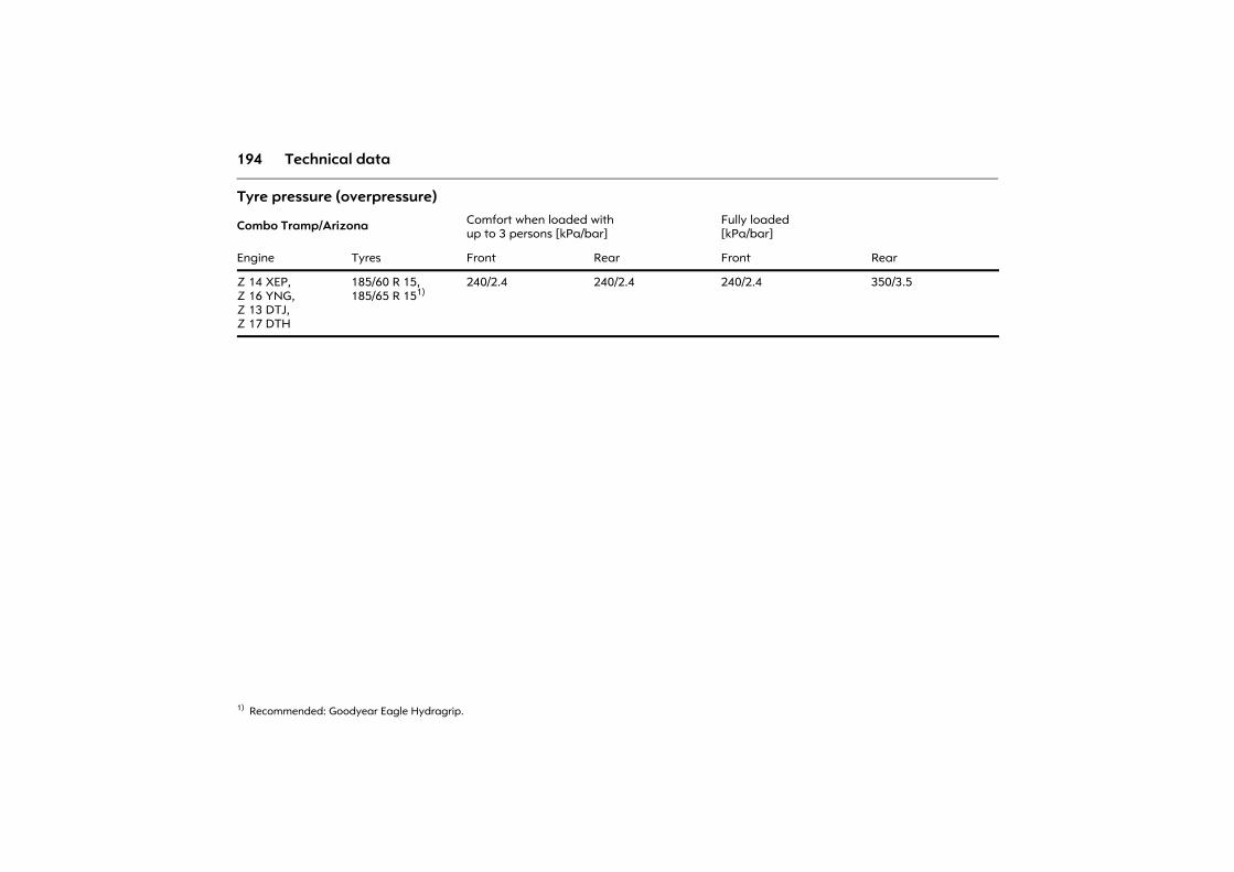
194 Technical data
Tyre pressure (overpressure)
Combo Tramp/Arizona Comfort when loaded withup to 3 persons [kPa/bar]
Fully loaded[kPa/bar]
Engine Tyres Front Rear Front Rear
Z 14 XEP,Z 16 YNG,Z 13 DTJ,Z 17 DTH
185/60 R 15,185/65 R 151)
1) Recommended: Goodyear Eagle Hydragrip.
240/2.4 240/2.4 240/2.4 350/3.5
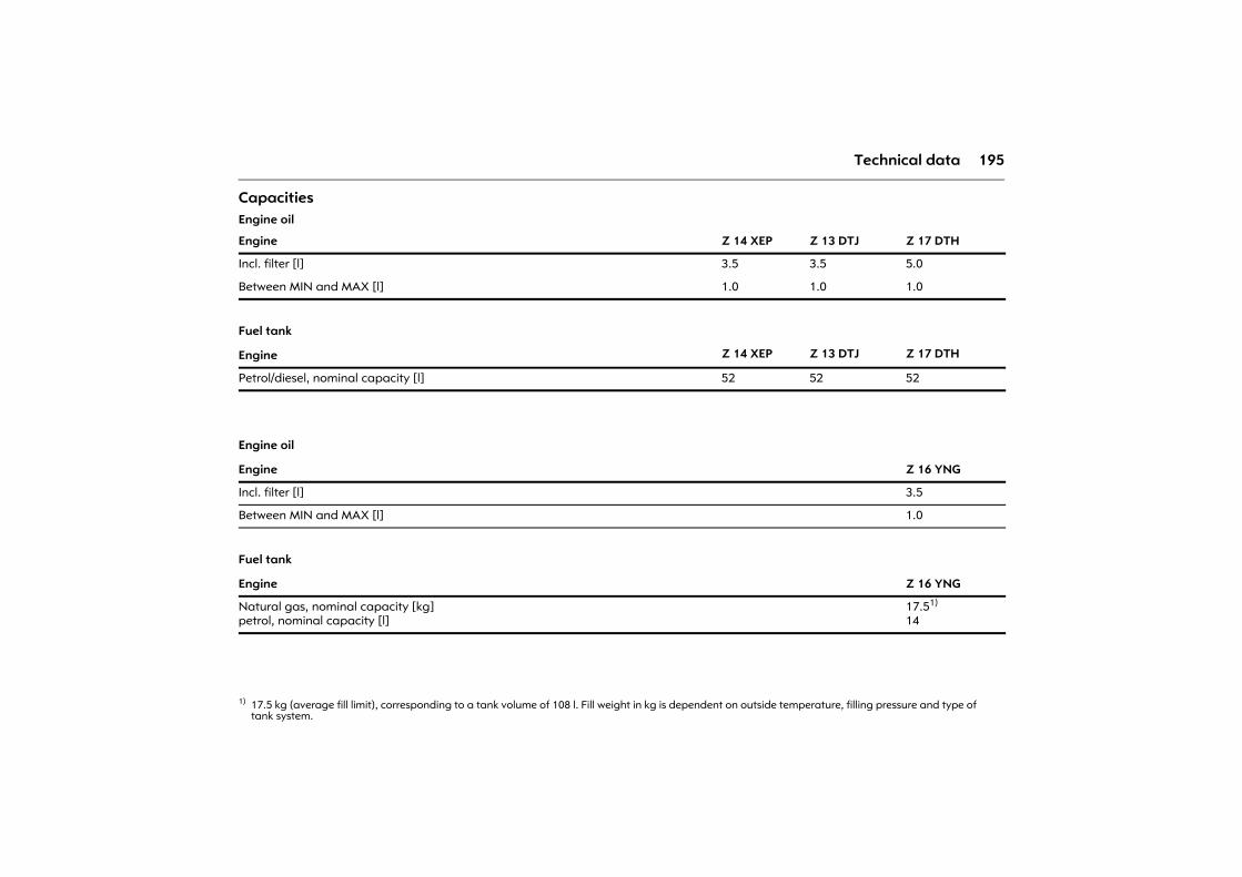
195Technical data
CapacitiesEngine oil
Engine Z 14 XEP Z 13 DTJ Z 17 DTH
Incl. filter [l] 3.5 3.5 5.0
Between MIN and MAX [l] 1.0 1.0 1.0
Fuel tank
Engine Z 14 XEP Z 13 DTJ Z 17 DTH
Petrol/diesel, nominal capacity [l] 52 52 52
Engine oil
Engine Z 16 YNG
Incl. filter [l] 3.5
Between MIN and MAX [l] 1.0
Fuel tank
Engine Z 16 YNG
Natural gas, nominal capacity [kg]petrol, nominal capacity [l]
17.51)
14
1) 17.5 kg (average fill limit), corresponding to a tank volume of 108 l. Fill weight in kg is dependent on outside temperature, filling pressure and type of tank system.
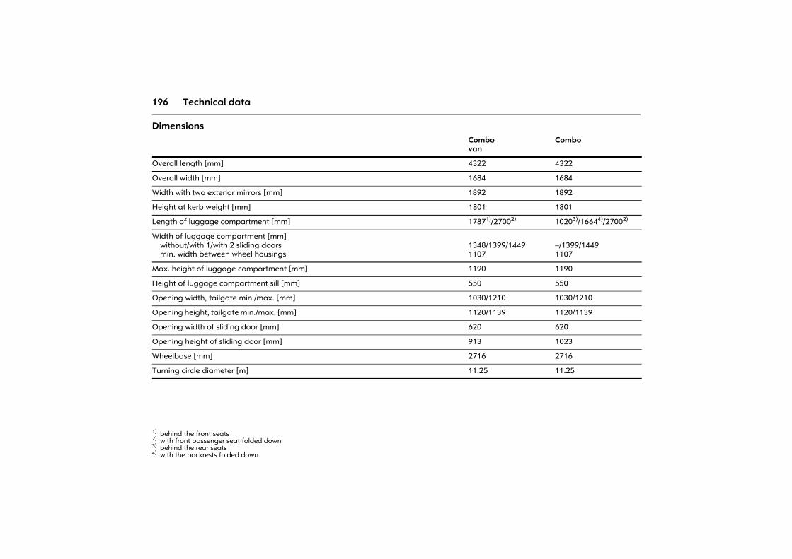
196 Technical data
DimensionsCombovan
Combo
Overall length [mm] 4322 4322
Overall width [mm] 1684 1684
Width with two exterior mirrors [mm] 1892 1892
Height at kerb weight [mm] 1801 1801
Length of luggage compartment [mm] 17871)/27002)
1) behind the front seats 2) with front passenger seat folded down
10203)/16644)/27002)
3) behind the rear seats 4) with the backrests folded down.
Width of luggage compartment [mm]without/with 1/with 2 sliding doorsmin. width between wheel housings
1348/1399/14491107
�/1399/14491107
Max. height of luggage compartment [mm] 1190 1190
Height of luggage compartment sill [mm] 550 550
Opening width, tailgate min./max. [mm] 1030/1210 1030/1210
Opening height, tailgate min./max. [mm] 1120/1139 1120/1139
Opening width of sliding door [mm] 620 620
Opening height of sliding door [mm] 913 1023
Wheelbase [mm] 2716 2716
Turning circle diameter [m] 11.25 11.25
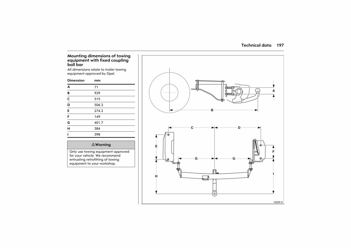
197Technical data
Mounting dimensions of towing equipment with fixed coupling ball bar All dimensions relate to trailer towing equipment approved by Opel.
Dimension mm
A 71
B 929
C 515
D 506.3
E 274.3
F 149
G 401.7
H 384
I 398
9 Warning
Only use towing equipment approved for your vehicle. We recommend entrusting retrofitting of towing equipment to your workshop.
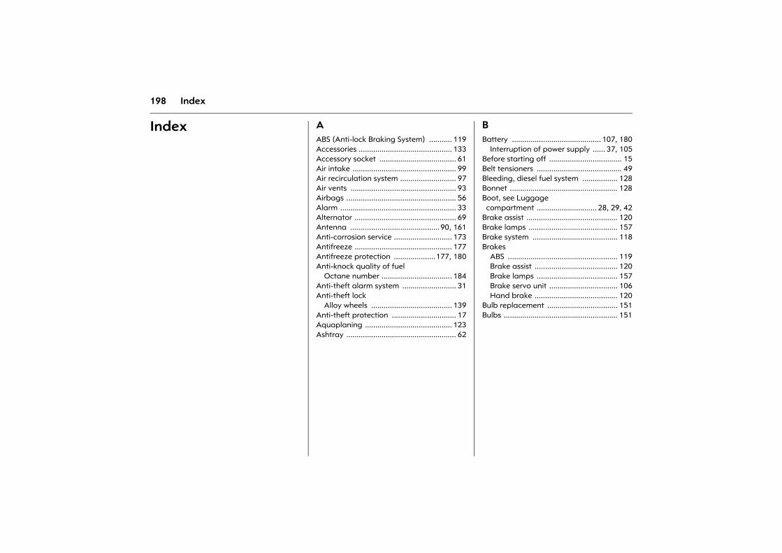
198 Index
Index AABS (Anti-lock Braking System) ........... 119Accessories ............................................. 133Accessory socket ..................................... 61Air intake .................................................. 99Air recirculation system ........................... 97Air vents ................................................... 93Airbags ..................................................... 56Alarm ........................................................ 33Alternator ................................................. 69Antenna ........................................... 90, 161Anti-corrosion service ............................ 173Antifreeze ............................................... 177Antifreeze protection ....................177, 180Anti-knock quality of fuel
Octane number .................................. 184Anti-theft alarm system .......................... 31Anti-theft lock
Alloy wheels ....................................... 139Anti-theft protection ............................... 17Aquaplaning .......................................... 123Ashtray ..................................................... 62
BBattery ........................................... 107, 180
Interruption of power supply ...... 37, 105Before starting off ................................... 15Belt tensioners ......................................... 49Bleeding, diesel fuel system ................. 128Bonnet .................................................... 128Boot, see Luggage compartment ............................. 28, 29, 42
Brake assist ............................................ 120Brake lamps ........................................... 157Brake system ......................................... 118Brakes
ABS ..................................................... 119Brake assist ........................................ 120Brake lamps ....................................... 157Brake servo unit ................................. 106Hand brake ........................................ 120
Bulb replacement .................................. 151Bulbs ....................................................... 151
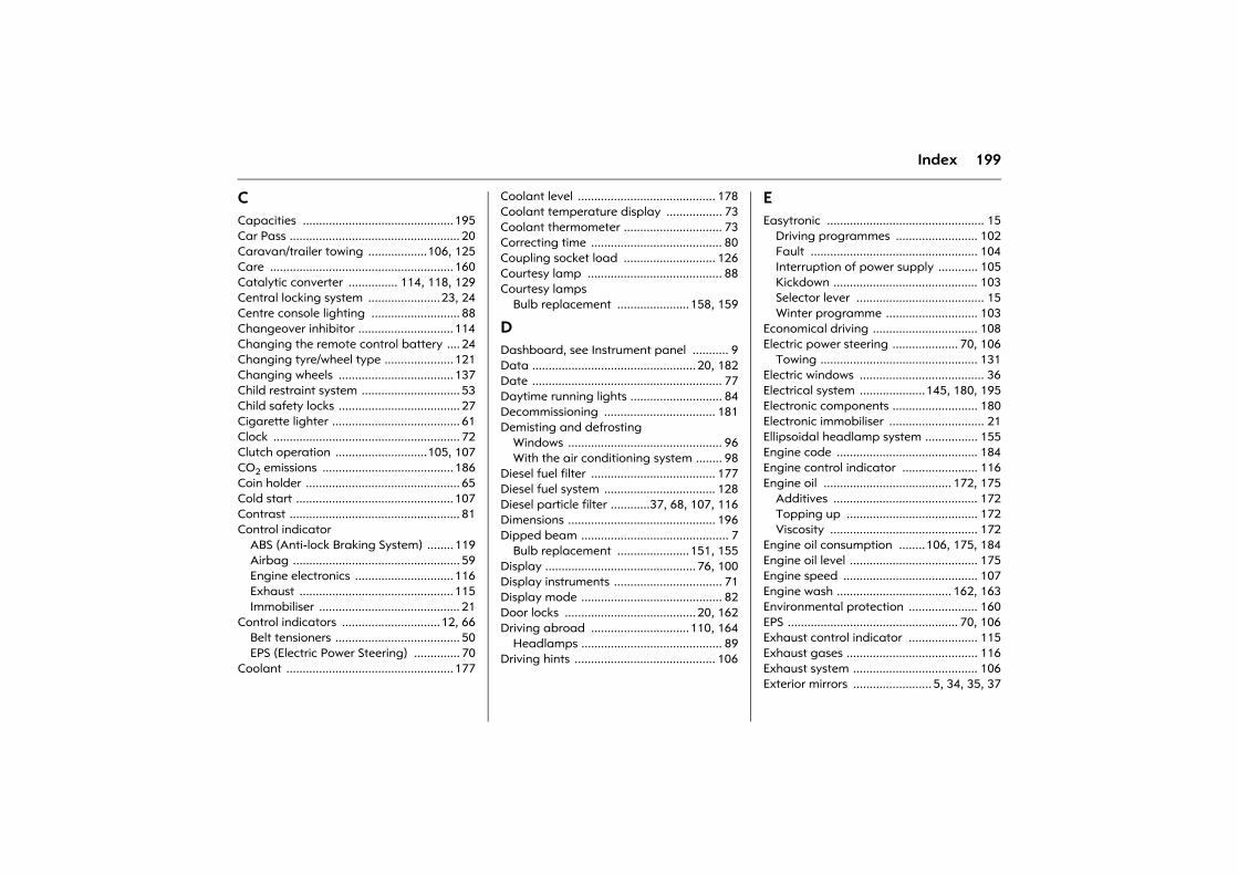
199Index
CCapacities .............................................. 195Car Pass .................................................... 20Caravan/trailer towing ..................106, 125Care ........................................................ 160Catalytic converter ............... 114, 118, 129Central locking system ......................23, 24Centre console lighting ........................... 88Changeover inhibitor ............................. 114Changing the remote control battery .... 24Changing tyre/wheel type ..................... 121Changing wheels ................................... 137Child restraint system .............................. 53Child safety locks ..................................... 27Cigarette lighter ....................................... 61Clock ......................................................... 72Clutch operation ............................105, 107CO2 emissions ........................................ 186Coin holder ............................................... 65Cold start ................................................ 107Contrast .................................................... 81Control indicator
ABS (Anti-lock Braking System) ........ 119Airbag ................................................... 59Engine electronics .............................. 116Exhaust ............................................... 115Immobiliser ........................................... 21
Control indicators ..............................12, 66Belt tensioners ...................................... 50EPS (Electric Power Steering) .............. 70
Coolant ................................................... 177
Coolant level .......................................... 178Coolant temperature display ................. 73Coolant thermometer .............................. 73Correcting time ........................................ 80Coupling socket load ............................ 126Courtesy lamp ......................................... 88Courtesy lamps
Bulb replacement ......................158, 159
DDashboard, see Instrument panel ........... 9Data .................................................. 20, 182Date .......................................................... 77Daytime running lights ............................ 84Decommissioning .................................. 181Demisting and defrosting
Windows ............................................... 96With the air conditioning system ........ 98
Diesel fuel filter ...................................... 177Diesel fuel system .................................. 128Diesel particle filter ............37, 68, 107, 116Dimensions ............................................. 196Dipped beam ............................................. 7
Bulb replacement ......................151, 155Display .............................................. 76, 100Display instruments ................................. 71Display mode ........................................... 82Door locks ........................................ 20, 162Driving abroad ..............................110, 164
Headlamps ........................................... 89Driving hints ........................................... 106
EEasytronic ................................................ 15
Driving programmes ......................... 102Fault ................................................... 104Interruption of power supply ............ 105Kickdown ............................................ 103Selector lever ....................................... 15Winter programme ............................ 103
Economical driving ................................ 108Electric power steering .................... 70, 106
Towing ................................................ 131Electric windows ...................................... 36Electrical system ....................145, 180, 195Electronic components .......................... 180Electronic immobiliser ............................. 21Ellipsoidal headlamp system ................ 155Engine code ........................................... 184Engine control indicator ....................... 116Engine oil ....................................... 172, 175
Additives ............................................ 172Topping up ........................................ 172Viscosity ............................................. 172
Engine oil consumption ........106, 175, 184Engine oil level ....................................... 175Engine speed ......................................... 107Engine wash ................................... 162, 163Environmental protection ..................... 160EPS .................................................... 70, 106Exhaust control indicator ..................... 115Exhaust gases ........................................ 116Exhaust system ...................................... 106Exterior mirrors ........................ 5, 34, 35, 37
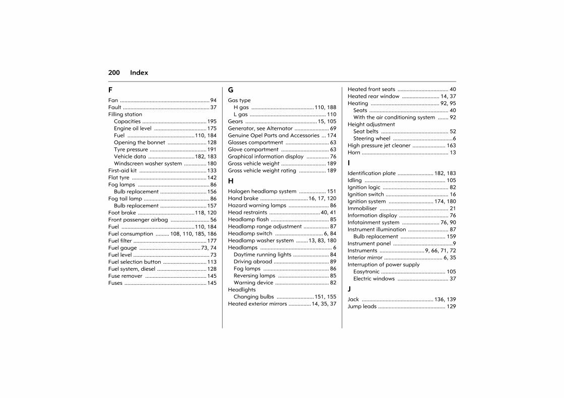
200 Index
FFan ............................................................ 94Fault .......................................................... 37Filling station
Capacities ........................................... 195Engine oil level ................................... 175Fuel .............................................110, 184Opening the bonnet .......................... 128Tyre pressure ...................................... 191Vehicle data ...............................182, 183Windscreen washer system ............... 180
First-aid kit ............................................. 133Flat tyre .................................................. 142Fog lamps ................................................ 86
Bulb replacement ............................... 156Fog tail lamp ............................................ 86
Bulb replacement ............................... 157Foot brake ......................................118, 120Front passenger airbag .......................... 56Fuel .................................................110, 184Fuel consumption ......... 108, 110, 185, 186Fuel filter ................................................. 177Fuel gauge .........................................73, 74Fuel level ................................................... 73Fuel selection button ............................. 113Fuel system, diesel ................................. 128Fuse remover ......................................... 145Fuses ....................................................... 145
GGas type
H gas ..........................................110, 188L gas ................................................... 110
Gears ................................................ 15, 105Generator, see Alternator ....................... 69Genuine Opel Parts and Accessories ... 174Glasses compartment ............................. 63Glove compartment ................................ 63Graphical information display ............... 76Gross vehicle weight .............................. 189Gross vehicle weight rating .................. 189
HHalogen headlamp system .................. 151Hand brake ................................16, 17, 120Hazard warning lamps ........................... 86Head restraints .................................. 40, 41Headlamp flash ....................................... 85Headlamp range adjustment ................. 87Headlamp switch ................................ 6, 84Headlamp washer system ........13, 83, 180Headlamps ................................................ 6
Daytime running lights ........................ 84Driving abroad ..................................... 89Fog lamps ............................................ 86Reversing lamps .................................. 85Warning device .................................... 82
HeadlightsChanging bulbs .........................151, 155
Heated exterior mirrors ...............14, 35, 37
Heated front seats .................................. 40Heated rear window ......................... 14, 37Heating .............................................. 92, 95
Seats ..................................................... 40With the air conditioning system ....... 92
Height adjustmentSeat belts ............................................. 52Steering wheel ........................................6
High pressure jet cleaner ...................... 163Horn .......................................................... 13
IIdentification plate ........................ 182, 183Idling ...................................................... 105Ignition logic ............................................ 82Ignition switch .......................................... 16Ignition system .............................. 174, 180Immobiliser .............................................. 21Information display ................................. 76Infotainment system ......................... 76, 90Instrument illumination ........................... 87
Bulb replacement .............................. 159Instrument panel ........................................9Instruments .............................. 9, 66, 71, 72Interior mirror ....................................... 6, 35Interruption of power supply
Easytronic ........................................... 105Electric windows .................................. 37
JJack ................................................ 136, 139Jump leads ............................................. 129
201Index
KKey
Extending ............................................. 20Ignition lock .......................................... 16Locking doors ...........................20, 23, 24Remove ................................................. 17Starting ...........................................16, 21Starting the engine .............................. 16
Keys ......................................................2, 20
LLanguage selection ................................. 80Lashing eyes ............................................ 44Leaf doors ......................................3, 22, 29Light switch ................................................ 6Lighting ................................................ 6, 84
Driving abroad ..................................... 89Load compartment
Loading ................................................ 47Load compartment grille ........................ 46Loading ............................................47, 126Loading the vehicle ................................. 47Locking doors ..............................20, 23, 24Locking from the inside .....................22, 25Locking the doors ..........................2, 22, 24Locks ....................................................... 162Lubricants .............................................. 175
Luggage compartment .......................... 28Bulb replacement .............................. 158Cover .................................................... 44Extension .............................................. 42Lashing eyes ........................................ 44Lighting ................................................ 88Loading ................................47, 126, 189Locking ................................................. 28
Luggage compartment cover ................ 44
MMain beam ........................................... 7, 85
Bulb replacement .............................. 152Control indicator .................................. 68
MaintenanceAir conditioning system ....................... 99Antifreeze protection ........................ 177Brake fluid .......................................... 179Brakes ................................................. 178Catalytic converter ............................ 118Engine oil ............................................ 175Fuel consumption .............................. 109Tyre pressure ...................................... 121Tyres ...........................................122, 123
Manual transmission ............................. 105Manual transmission, see Transmission 15Mirrors ............................................ 6, 34, 35Misted windows ................................. 96, 98Mobile telephone ..................................... 91Muffler, see Exhaust system ................. 116
NNatural gas ..............................74, 110, 113Number plate lamps
Bulb replacement .............................. 158Number plate lighting .......................... 158
OOctane numbers .................................... 184Odometer ................................................. 71Oil ........................................................... 172
Additives ............................................ 172Topping up ........................................ 172Viscosity ............................................. 172
Oil consumption ............................ 175, 184Oil level ................................................... 175Oil pressure .............................................. 67Opel Service ........................................... 164Operating temperature ........................ 107Outside temperature gauge .................. 76Overrun .......................................... 107, 109
202 Index
PPaintwork damage ................................ 161Parking ..................................................... 17Parking lamps ............................................ 6
Bulb replacement ............................... 153Parking the vehicle .................................. 17Parts ........................................................ 174Pedals ..................................................... 107Performance ...................................185, 186Petrol ...................................................... 184Pollen filter ............................................... 99Power steering, see electric power steering ............70, 106
Power-assisted steering, see electric power steering ............70, 106
Preheater start switch ............................. 16Preheating ................................................ 68Pushing, towing ..................................... 129
RRadio ........................................................ 90Radio equipment (CB) ............................. 91Radio reception ....................................... 90Rear lamp cluster .................................... 84
Bulb replacement .............................. 157Rear seat backrests ................................. 42Rear window washer system .................14, 83, 161, 180
Rear window wiper ............................ 14, 83Refuelling
Fuel filler cap ...................................... 111Fuel gauge ..................................... 73, 74
Relays ..................................................... 145Remote control ........................................ 23
Central locking system ........................ 23Steering wheel ...................................... 90
Replacement keys ................................... 20Reversing lamps ...................................... 85
Bulb replacement .............................. 157Roof load ..................................47, 106, 109Roof rack ..................................47, 109, 125Roof racks ................................47, 109, 125Running-in .............................................. 106
Brakes ................................................. 178
SSafeguard against Unauthorised use ................16, 17, 20, 21
Safety accessories ................................. 133Safety net ................................................. 45Saving energy ........................................ 108Seat adjustment ...................................... 38Seat belts ......................................... 52, 162Seat height adjustment ...................... 4, 39Seat position ............................................ 39Seats ..................................................... 3, 38
Heated ................................................. 40Self-diagnosis ............................ 51, 60, 120Self-help ................................................. 128
Central locking ..................................... 26Electric windows .................................. 36Information display ............................. 77Radio remote control .......................... 23
Service interval display ......................... 173Service intervals ..................................... 164
Additional work ................................. 171Extreme operating conditions .......... 171Main service ....................................... 164
Service work ........................................... 173Side airbags ............................................. 58
203Index
Signal system ........................................... 13Sliding doors ............................................ 27Spare fuses ............................................. 145Spare keys ................................................ 20Spare wheel ....................................134, 137Speed ..............................................108, 109
Fuel consumption ......................108, 109Speedometer ............................................ 71Starter switch ........................................... 16Starting the engine ....................16, 21, 129
Self-help .............................................. 129Steam jet cleaner ................................... 163Steering column lock .........................16, 17Steering wheel adjustment ....................... 6Steering wheel remote control ..........19, 90Stowage compartments ..............39, 63, 64Sun visors .................................................. 65System settings ........................................ 79
TTachometer .............................................. 71Tail lamps ................................................. 84
Bulb replacement ............................... 157Tailgate ................................................ 2, 28Technical data ....................................... 182Telephone, see Mobile telephone .......... 91Temperature regulation .......................... 94Temporary spare wheel ................125, 135The first 1000 km ................................... 106
Tightening torque ..........................141, 191Time .......................................................... 77Tools ....................................................... 136Towing .................................................... 131Towing equipment ................................ 126Towing eye .....................................131, 133Transmission, Easytronic
Driving programmes ......................... 102Fault .................................................... 104Interruption of power supply ............ 105Kickdown ............................................ 103Selector lever ........................................ 15Winter programme ............................ 103
Transmission, manual ..................... 15, 105Tread depth ........................................... 123Trip odometer .......................................... 72Triple information display ....................... 76Turn signal lamps ................................ 7, 85Turn signals
Bulb replacement ..............154, 156, 157Tyre chains ............................................. 125Tyre condition ........................................ 122Tyre pressure .................................121, 191Tyre repair kit ........................................ 142
UUnderbody wash ................................... 163Units of measure ..................................... 81Unleaded fuel ................................114, 184
VValve cap key ........................................ 121Vehicle care ........................................... 160Vehicle decommissioning ..................... 181Vehicle identification number .............. 183Vehicle keys, see Keys ............................ 20Vehicle recommissioning ...................... 181Vehicle tools .......................................... 136Ventilation ............................................... 92VIN, see Vehicle Identification Number ..... 182
204 Index
WWarning buzzers ...................................... 82Warning triangle .................................... 133Washer fluid reservoir, windscreen washer system ................. 180
Wheel trim .............................................. 124Wheels .................................................... 121Wheels, tyres .......................................... 121Windows
Demisting and defrosting .............96, 98Windscreen washer system .......13, 83, 180
Antifreeze protection ......................... 180Washer fluid reservoir ........................ 180
Windscreen wipers .....................13, 82, 179Winter mode
Starting-off aid .................................. 103Winter operation
Battery ................................................ 107Coolant, antifreeze ............................ 177Fuel consumption .............................. 109Fuel for diesel engines ....................... 110Heating ................................................. 92Locks ................................................... 162Tyre chains ......................................... 125Window demisting and defrosting ...............................96, 98Windscreen washer system, antifreeze protection ......................... 180
Winter programme ................................ 103Winter tyres ....................................124, 191

Copyright by ADAM OPEL GmbH, Rüsselsheim, Germany.
The information contained in this publication is valid as of the date indicated below. Adam Opel GmbH reserves the right to make changes to the technical specifications, features and design of the vehicles relative to the information contained in this publication, as well as changes to the publication itself.
Edition: August 2008, ADAM OPEL GmbH, Rüsselsheim.
Printed on chlorine-free bleached paper.
KTA-2387/12-GB 24 439 257 Art.-Nr. 09 927 0412 08/2008


![N Группа Модель Артикул · 96 Opel OPEL Astra TwinTop [H] 09.05-10.10 106432 550 450 1 side pin 97 Opel OPEL Combo [D] 02.12-> 106418 600 400 3 push button 98 Opel](https://img.pdfslide.net/doc/110x75/5ec076988e5cd70a9a4744e3/n-f-oeoe-f-96-opel-opel-astra-twintop-h-0905-1010.jpg)