Embed Size (px)
Citation preview

Hence its Light, This is "LT"!Handy
Easy
Open Field NetworkCC-Link/LT Compatible Product Catalog
For safe useMitsubishi will not be held liable for damage caused by factors found not to be the cause of Mitsubishi; machine damage or lost profits caused by faults in the Mitsubishi products; damage, secondary damage, accident compensation caused by special factors unpredictable by Mitsubishi; damages to products other than Mitsubishi products; and to other duties.
Precautions for Choosing the Products
L(NA)-08026E-A 0208(MEE)
When exported from Japan, this manual does not require application to theMinistry of International Trade and Industry for service transaction permission.
New publication,effective Aug. 2002
Specifications subject to change without notice.
Printed in Japan on recycled paper.
ELECTRIC CORPORATION HEAD OFFICE: 1-8-12,OFFICE TOWER Z 14F HARUMI CHUO-KU 104-6212,JAPAN
NAGOYA WORKS: 1-14,YADA-MINAMI 5,HIGASHI-KU,NAGOYA,JAPAN
Country/Region Sales office Tel/Fax
U.S.A Mitsubishi Electric Automation Inc. Tel : +1-847-478-2100500 Corporate Woods Parkway Vernon Hills, IL 60061 Fax : +1-847-478-0328
Brazil MELCO-TEC Rep. Com.e Assessoria Tecnica Ltda. Tel : +55-21-221-8343Av. Rio Branco, 123-15 ,and S/1507, Rio de Janeiro, RJ CEP 20040-005, Brazil Fax : +55-21-221-9388
Germany Mitsubishi Electric Europe B.V. German Branch Tel : +49-2102-486-0Gothaer Strasse 8 D-40880 Ratingen, GERMANY Fax : +49-2102-486-717
U.K Mitsubishi Electric Europe B.V. UK Branch Tel : +44-1707-276100Travellers Lane, Hatfield, Herts., AL10 8XB,UK Fax : +44-1707-278695
Italy Mitsubishi Electric Europe B.V. Italian Branch Tel : +39-039-60531Centro Dir. Colleoni, Pal. Perseo - Ingr.2 Fax : +39-039-6053312Via Paracelso 12, 20041 Agrate B., Milano, Italy
Spain Mitsubishi Electric Europe B.V. Spanish Branch Tel : +34-935-653135Carretera de Rubi 76-80 Fax : +34-935-89157908190 Sant Cugat del Valles, Barcelona, Spain
South Africa Circuit Breaker Industries LTD Tel : +27-11-928-2000
Private Bag 2016, Isando 1600, Johannesburg, South Africa Fax : +27-11-392-2354
Hong Kong Ryoden Automation Ltd. Tel : +852-2887-887010th Floor, Manulife Tower, 169 Electric Road, North Point, HongKong Fax : +852-2887-7984
China Ryoden International Shanghai Ltd. Tel : +86-21-6475-32283F Block5 Building Automation Instrumentation Plaza 103 Fax : +86-21-6484-6996Cao Bao Rd. Shanghai 200233 China
Taiwan Setsuyo Enterprise Co., Ltd. Tel : +886-2-2299-24996F., No.105 Wu-Kung 3rd.RD, Wu-Ku Hsiang, Taipei Hsine, Taiwan Fax : +886-2-2299-2509
Korea HAN NEUNG TECHNO CO., LTD. Tel : +82-2-3660-95521F Dong Seo Game Channel Bldg., 660-11,Deungchon-dong Kangsec-ku, Fax : +82-2-3664-8372Seoul, Korea
Singapore Mitsubishi Electric Asia Pte, Ltd. Tel : +65-473-2480307 Alexandra Road #05-01/02, Fax : +65-476-7439Mitsubishi Electric Bulding Singapore 159943
Thailand F. A. Tech Co.,Ltd. Tel : +66-2-682-6522898/28,29,30 S.V.City Building, Office Tower 2, Floor Fax : +66-2-682-602017-18 Rama 3 Road, Bangkpongpang, Yannawa, Bangkok 10120
Indonesia P.T. Autoteknindo SUMBER MAKMUR Tel : +62-21-663-0833Jl. Muara Karang Selatan Blok a Utara No.1 Kav. Fax : +62-21-663-0832No.11 Kawasan Industri/Pergudangan Jakarta-Utara 14440
India Messung Systems Put,Ltd. Tel : +91-20-7128927Electronic Sadan NO:111 Unit No15, M.I.D.C BHOSARI,PUNE-411026,India Fax : +91-20-7128108
Australia Mitsubishi Electric Australia Pty. Ltd. Tel : +61-2-9684-7777348 Victoria Road, PostalBag, No 2, Rydalmere, N.S.W 2116, Australia Fax : +61-2-9684-7245
Mitsubishi Electric Corporation Nagoya Works is a factory certified for ISO14001 (standards for environmental management systems) and ISO9001 (standards for quality assurance management systems)
http://www.nagoya.melco.co.jp/english/
To use the products given in this catalog properly, always read the "manuals" before starting to use them.This product has been manufactured as a general-purpose part for general industries, and has not been designed or manufactured to be incorporated in a device or system used in purposes related to human life. Before using the product for special purposes such as nuclear power, electric power, aerospace, medicine or passenger movement vehicles, consult with Mitsubishi.This product has been manufactured under strict quality control. However, when installing the product where major accidents or losses could occur if the product fails, install appropriate backup or failsafe functions in the system.
Open Field NetworkCC-Link/LT Compatible Product Catalog
I N D E X
CC-Link/LT expands the range of open networkpossibilities to the far end of the plant floor.
4
6
8
10
12
14
16
30
30
31
31
32
32
33
33
34
36
38
PRODUCT INFORMATION
TECHNICAL INFORMATION
Inheriting The Global Standard CC-Link
LT Makes Its Debut.As a Japan-originated open field network, CC-Link is establishing track records As a Japan-originated open field network, CC-Link is establishing track records on a global basis.
Fully inheriting the CC-Link concept, CC-Link/LFully inheriting the CC-Link concept, CC-Link/LT makes its debut. makes its debut.
For use in machines such as semiconductor manufacturing and material handling, CFor use in machines such as semiconductor manufacturing and material handling, CC-Link/LC-Link/LT exhibits
its overwhelming performance including reduced wiring and fast link scans.its overwhelming performance including reduced wiring and fast link scans.
Mitsubishi has a wide variety of wire-saving network modules compatible with CC-Mitsubishi has a wide variety of wire-saving network modules compatible with CC-Link/LT.
Mitsubishi is developing the open network possibilities of CC-Link/LMitsubishi is developing the open network possibilities of CC-Link/LT that is optimum for reduced that is optimum for reduced
wiring and I/O point distribution.wiring and I/O point distribution.
As a Japan-originated open field network, CC-Link is establishing track records on a global basis.
Fully inheriting the CC-Link concept, CC-Link/LT makes its debut.
For use in machines such as semiconductor manufacturing and material handling, CC-Link/LT exhibits
its overwhelming performance including reduced wiring and fast link scans.
Mitsubishi has a wide variety of wire-saving network modules compatible with CC-Link/LT.
Mitsubishi is developing the open network possibilities of CC-Link/LT that is optimum for reduced
wiring and I/O point distribution.
Overview of Networks Provided by Mitsubishi
CC-Link Family
Features of CC-Link/LT
System Configuration Examples
Application Examples
Master Modules
Remote I/O Modules
Power Supply Adaptor
Accessories
Software
CC-Link/LT Dedicated Communication LSIs
CC-Link/LT-Specifications
Network Wiring Specifications
Cable Specifications
General Specifications
Power Supply Adaptor Installation
CC-Link Partner Association
CC-Link/LT Related Product Model List
O p e n L i n k o f W i r e - s a v i n g N e t w o r k s
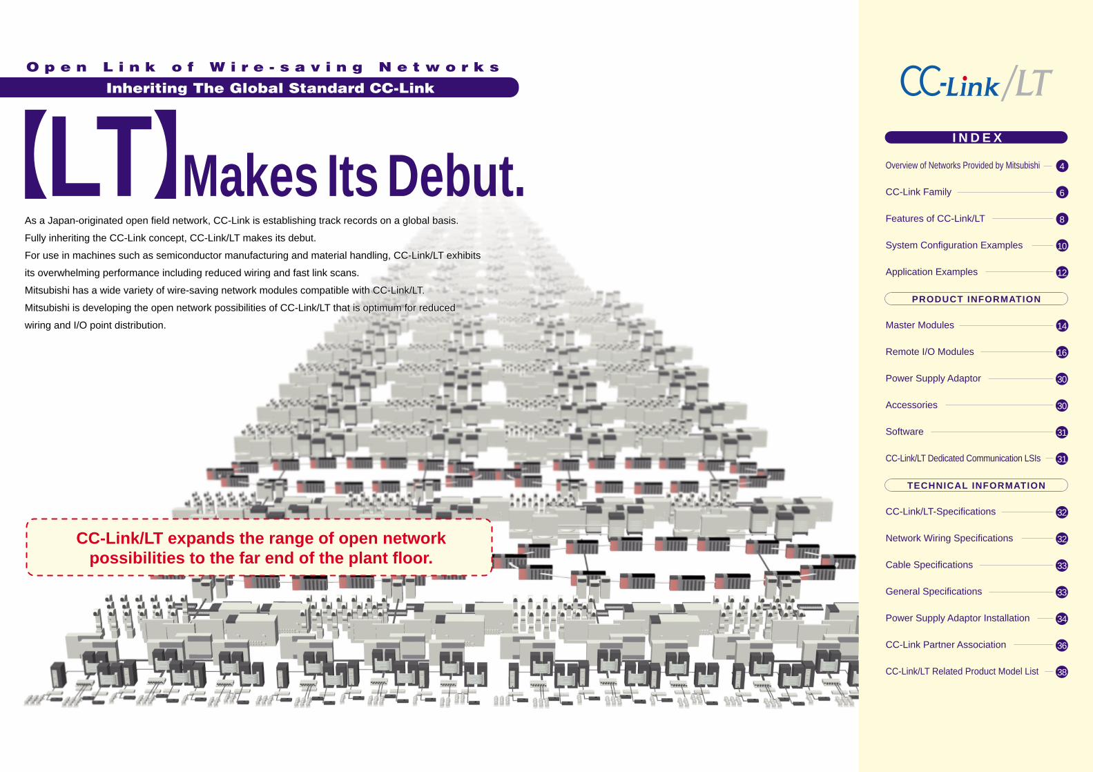
From information management to production control, machine control, device and I/O control ...Looking ahead to network interconnection in all of these layers, Mitsubishi has presented one product after another that are compatible with not only Ethernet but also MELSECNET/H and CC-Link.Now, Mitsubishi provides CC-Link/LT compatible, wire-saving network modules to achieveseamless network integration in all layers of Factory Automation system topology.Mitsubishi’s total network solution is in full development towards dynamic production activities.
Adding CC-Link/LT compatible products, Mitsubishi provides a total network solution.
Adding CC-Link/LT compatible products, Mitsubishi provides a total network solution.
4 5
Sensor Level(Device, I/O control)
Field Level(Machine control)
Controller Level(Production control)
Plant Level(Information management)
Ethernet
MELSECNET/H
CC-Link
CC-Link/LT
Remote I/O stations
CC-Link-CC-Link/LT bridge
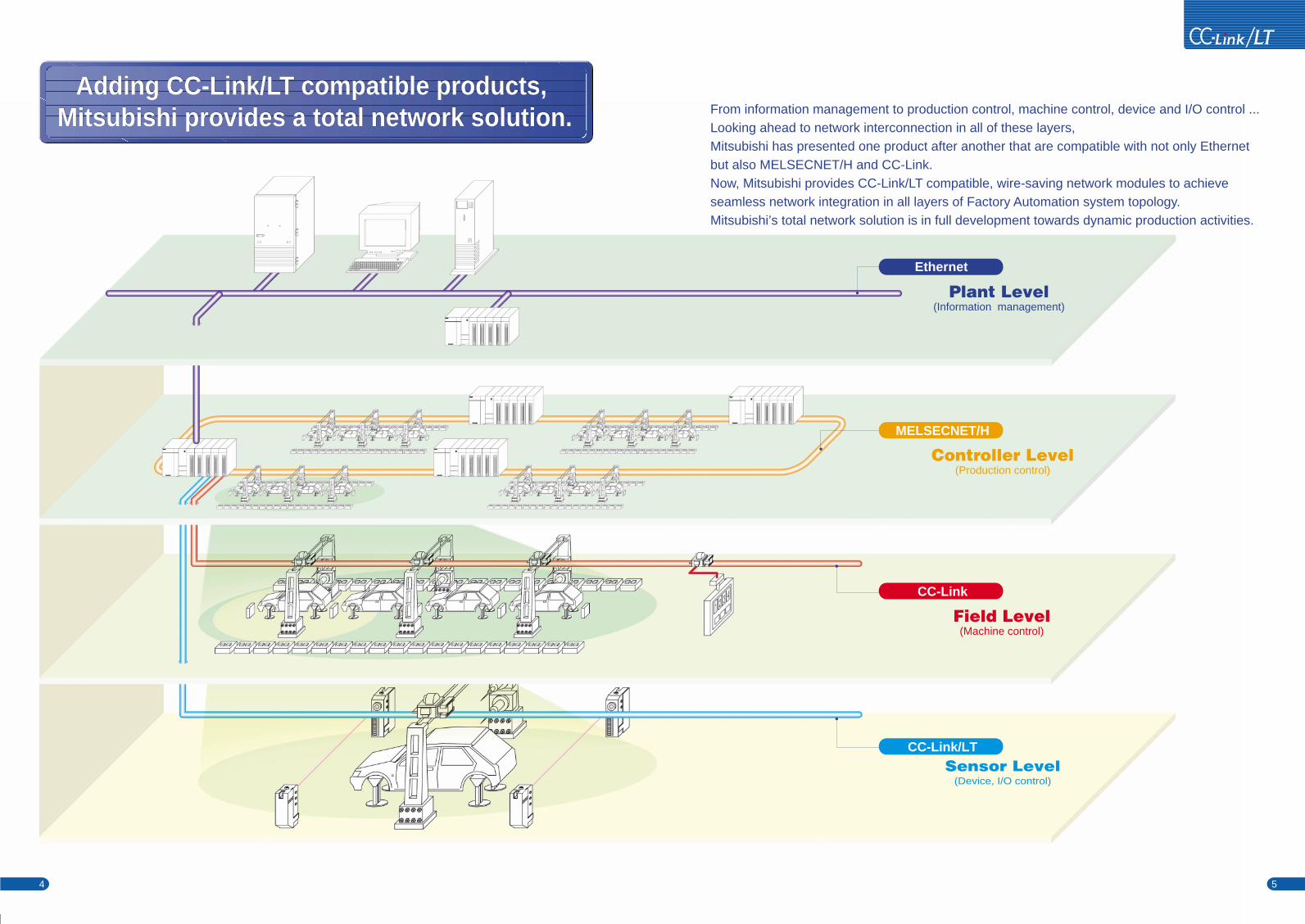
Fast response Ease of working by connection of connectors Ease of extension and addition Communication and power supply lines are integrated into one line.2-, 4-, 8- and 16-point remote I/O units are available.
As the Japan-originated global standard, CC-Link is increasing the range of field networkpossibilities."If we could seamlessly network the control field that ranges from machine control to deviceand I/O control in the integrated concept of CC-Link..."The reinforced CC-Link family is a new answer to such a request from the plant floor.
For networking inside a panel/machine
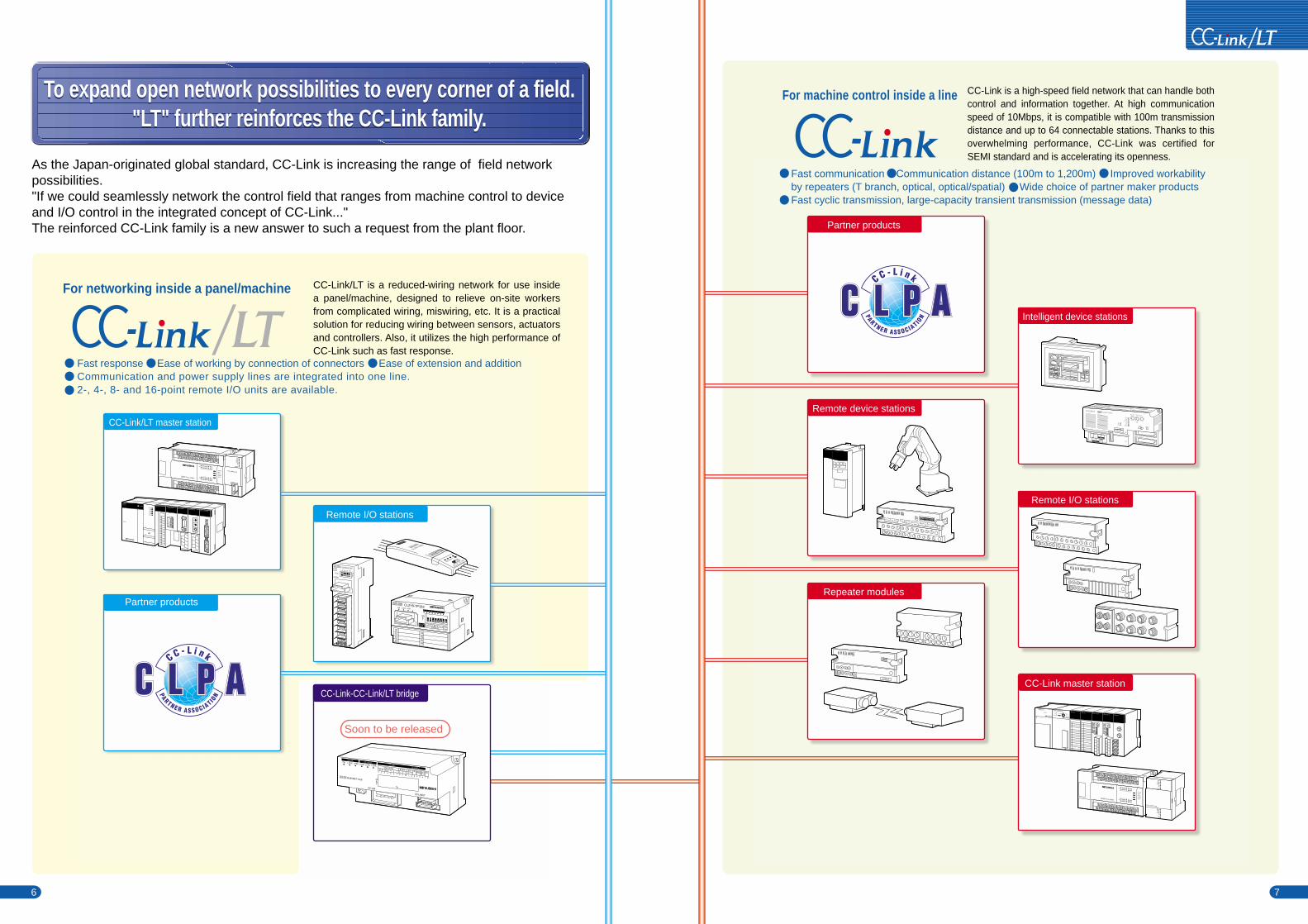
Fast communication Communication distance (100m to 1,200m) Improved workability by repeaters (T branch, optical, optical/spatial) Wide choice of partner maker productsFast cyclic transmission, large-capacity transient transmission (message data)
For machine control inside a line
CC-Link/LT is a reduced-wiring network for use inside a panel/machine, designed to relieve on-site workers from complicated wiring, miswiring, etc. It is a practical solution for reducing wiring between sensors, actuators and controllers. Also, it utilizes the high performance of CC-Link such as fast response.
CC-Link is a high-speed field network that can handle both control and information together. At high communication speed of 10Mbps, it is compatible with 100m transmission distance and up to 64 connectable stations. Thanks to this overwhelming performance, CC-Link was certified for SEMI standard and is accelerating its openness.
Partner products
Remote device stations
Repeater modules
Intelligent device stations
Remote I/O stations
CC-Link master station
Partner products
CC-Link/LT master station
To expand open network possibilities to every corner of a field."LT" further reinforces the CC-Link family.
To expand open network possibilities to every corner of a field."LT" further reinforces the CC-Link family.
6 7
USB
PULL
Q25HCPU
MODERUNERR
USERBAT
BOOT
RS-232
POWER
Q61P-A1
QJ71C24 QJ61BT11
QX10QJ61CL12
QJ71LP21-25
SW ON
12345678
NPO
B RATE
MODE
TEST
PULL
CL2X8-D1C3V
ST.No.
1 2 3 4 5 6 7 8
LINK/PW
IN
ON
CL2Y8-TP1B2
Y0Y1Y2Y3
Y4Y5Y6Y7
40 20 10 8 4 2 1
PW L RUN L ERR.
STATION NO.0.5ms1.5ms
ON
OUT
0 1 2 3 4 5 6 7
A2USCPU
RUN
ERROR
L.CLR
RESETRESET
RUN
STOP
RESET
A1SP60 A1SP60 A1SJ61BT11AD35ID1
A1SJ61BT11
A1S62P
POWER
FX2N-32MR
0 1 2 3 4 5 6 710 11 12 13 14 15 16 17
IN
0 1 2 3 4 5 6 710 11 12 13 14 15 16 17
IN
POWERRUNBATT.VPROG.ECPU.E
FX2N-16CCL-M
RUNERR.
L RUNL ERR.
SDRD
POWER
RUNERR.
L RUNL ERR.
SD
RDRD
FX2N-32MR
0 1 2 3 4 5 6 710 11 12 13 14 15 16 17
IN
0 1 2 3 4 5 6 710 11 12 13 14 15 16 17
IN
POWERRUNBATT.VPROG.ECPU.E
FX2N-64CL-M
RUNERR.
L RUNL ERR.
SDRD
POWER
CL1Y2-T1D2S
PW L RUN 0
STATION NO.
402010 8 4 2 1HLD
COMM.
1
24G X0 Y0 +24VIN OUT
AJ65SBT-CLB
40 20 10 8 4 2 1 4 2 1 2 1 2 1 2 1
PW L RUN L ERR.
STATION NO. B RATE NOS TST MODE B RATE NC
ON
CC-Link
CC-Link/LT
1 2 3 4 5 6 7 8 9 10 1 2 3 4 5 6 7 8
CC-Link
L RUN L ERR. L ERR.
CC-Link/LTCC-Link
CC-Link/LT
Soon to be released
8 9
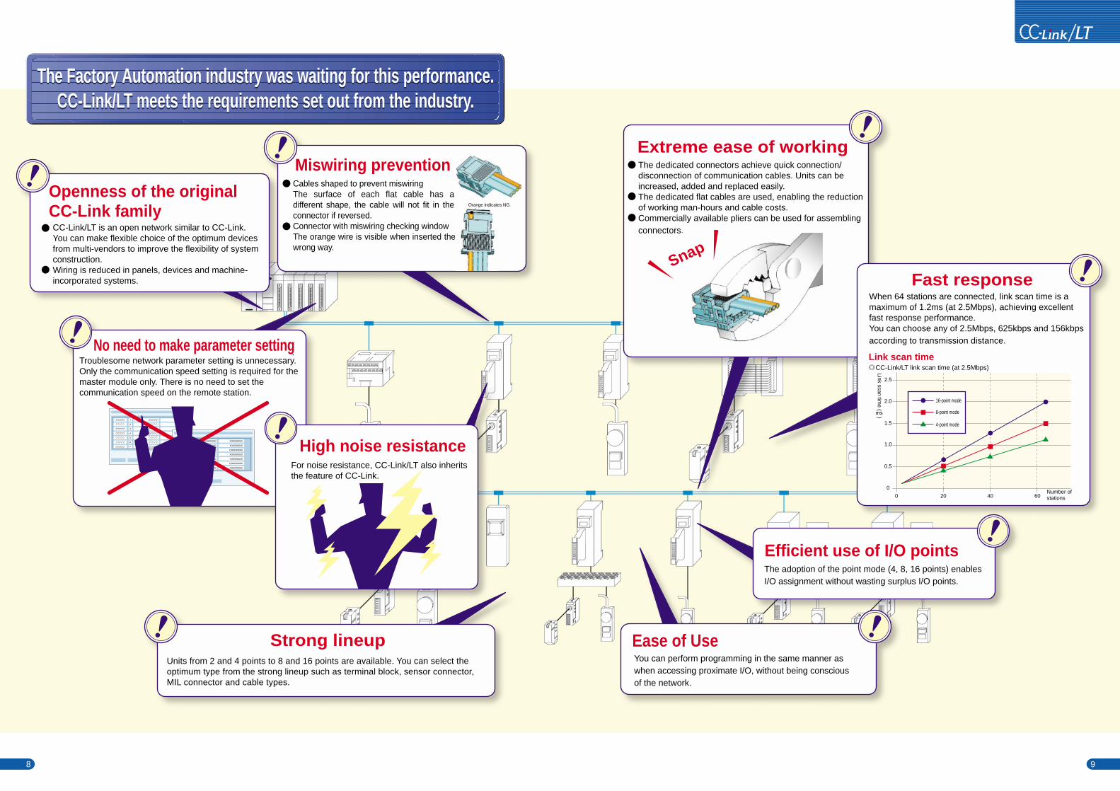
The Factory Automation industry was waiting for this performance.CC-Link/LT meets the requirements set out from the industry.
The Factory Automation industry was waiting for this performance.CC-Link/LT meets the requirements set out from the industry.
Openness of the originalCC-Link family CC-Link/LT is an open network similar to CC-Link. You can make flexible choice of the optimum devicesfrom multi-vendors to improve the flexibility of systemconstruction.Wiring is reduced in panels, devices and machine-incorporated systems.
Ease of UseYou can perform programming in the same manner aswhen accessing proximate I/O, without being conscious of the network.
The adoption of the point mode (4, 8, 16 points) enablesI/O assignment without wasting surplus I/O points.
Efficient use of I/O points
Strong lineupUnits from 2 and 4 points to 8 and 16 points are available. You can select the optimum type from the strong lineup such as terminal block, sensor connector, MIL connector and cable types.
Extreme ease of workingThe dedicated connectors achieve quick connection/disconnection of communication cables. Units can beincreased, added and replaced easily.The dedicated flat cables are used, enabling the reductionof working man-hours and cable costs.Commercially available pliers can be used for assembling connectors.
Snap
No need to make parameter settingTroublesome network parameter setting is unnecessary.Only the communication speed setting is required for the master module only. There is no need to set the communication speed on the remote station.
X000000000
Y000000000
D000000000
X000000000
Y000000000
D000000000
X000000000
X000000000
Y000000000
D000000000
X000000000
Y000000000
D000000000
X000000000 For noise resistance, CC-Link/LT also inherits the feature of CC-Link.
High noise resistance
Miswiring preventionCables shaped to prevent miswiringThe surface of each flat cable has a different shape, the cable will not fit in the connector if reversed.Connector with miswiring checking windowThe orange wire is visible when inserted the wrong way.
Fast responseWhen 64 stations are connected, link scan time is a maximum of 1.2ms (at 2.5Mbps), achieving excellentfast response performance. You can choose any of 2.5Mbps, 625kbps and 156kbpsaccording to transmission distance.
Link scan timeCC-Link/LT link scan time (at 2.5Mbps)
2.5
2.0
1.5
1.0
0.5
0
0 20 40 60
Link scan time ( )
Number ofstations
16-point mode
8-point mode
4-point mode
Orange indicates NG.
ms
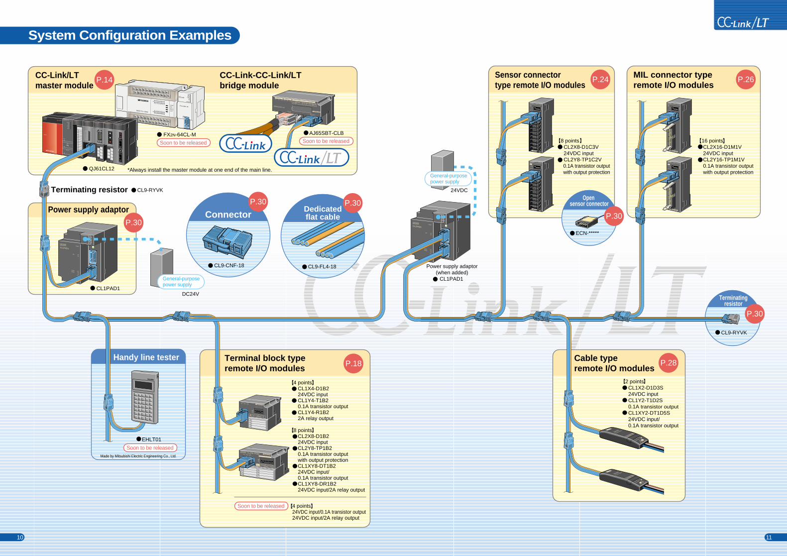
System Configuration Examples
CC-Link/LTmaster module
CC-Link-CC-Link/LTbridge module
Terminal block typeremote I/O modules
Cable typeremote I/O modules
MIL connector typeremote I/O modules
Power supply adaptor
FX2N-64CL-M
QJ61CL12 *Always install the master module at one end of the main line.
CL1PAD1
CL1PAD1
EHLT01
Made by Mitsubishi Electric Engineering Co., Ltd.
Handy line tester
Terminatingresistor
Terminating resistor
2 points CL1X2-D1D3S 24VDC input CL1Y2-T1D2S 0.1A transistor output CL1XY2-DT1D5S 24VDC input/ 0.1A transistor output
8 points CL2X8-D1C3V 24VDC input CL2Y8-TP1C2V 0.1A transistor output with output protection
P.14 P.26
P.30
P.18 P.28
P.30
AJ65SBT-CLB
CL9-RYVK
CL9-RYVK
Sensor connectortype remote I/O modules
P.24
CL9-CNF-18
ConnectorP.30
16 points CL2X16-D1M1V 24VDC input CL2Y16-TP1M1V 0.1A transistor output with output protection
Open sensor connector
ECN-*****
P.30
10 11
CL9-FL4-18
Dedicatedflat cable
P.30
4 points CL1X4-D1B2 24VDC input CL1Y4-T1B2 0.1A transistor output CL1Y4-R1B2 2A relay output
8 points CL2X8-D1B2 24VDC input CL2Y8-TP1B2 0.1A transistor output with output protection CL1XY8-DT1B2 24VDC input/ 0.1A transistor output CL1XY8-DR1B2 24VDC input/2A relay output
4 points24VDC input/0.1A transistor output24VDC input/2A relay output
Soon to be released Soon to be released
Soon to be released
Soon to be released
CL1PAD1POWER
+24V
24G
DBDA
24GDBDA
+24V
LCNET/POWER
LINK
CL1PAD1POWER
+24V
24G
DBDA
24GDBDA
+24V
LCNET/POWER
LINK
FX2N-32MR
0 1 2 3 4 5 6 710 11 12 13 14 15 16 17
IN
0 1 2 3 4 5 6 710 11 12 13 14 15 16 17
IN
POWERRUNBATT.VPROG.ECPU.E
PULL
USB
PULL
Q25HCPU
MODERUNERR
USERBAT
BOOT
RS-232
POWER
Q61P-A1
QJ71C24 QJ61BT11
QX10QJ61CL12
QJ71LP21-25
SW ON
12345678
NPO
B RATE
MODE
TEST
CL2Y8-TP1B2
Y0Y1Y2Y3
Y4Y5Y6Y7
40 20 10 8 4 2 1
PW L RUN L ERR.
STATION NO.0.5ms1.5ms
ON
OUT
0 1 2 3 4 5 6 7
IN
X0X1X2X3
0 1 2 3
PW L RUN L ERR.
STATION NO.
ON
PW
L RUN
L ERR.
0123456789ABCDEF
CL2X16-D1M1V
ST.No.
1 2 3 4 5 6 7 8
LINK/PW
IN
ON
PW
L RUN
L ERR.
0123456789ABCDEF
CL2Y16-TP1M1V
ST.No.
1 2 3 4 5 6 7 8
LINK/PW
OUT
ON
CL2X8-D1C3V
ST.No.
1 2 3 4 5 6 7 8
LINK/PW
IN
CL2Y8-TP1C2V
ST.No.
1 2 3 4 5 6 7 8
LINK/PW
OUT
ON
ON
DC24V
24VDC
Power supply adaptor(when added)
CL1Y2-T1D2S
PW L RUN 0
STATION NO.
402010 8 4 2 1HLD
COMM.
1
24G X0 Y0 +24VIN OUT
CL1X2-D1D3S
PW L RUN 0
STATION NO.
402010 8 4 2 1HLD
COMM.
1
24G X0 Y0 +24VIN OUT
FX2N-64CL-M
RUNERR.
L RUNL ERR.
SDRD
POWER
AJ65SBT-CLB
40 20 10 8 4 2 1 4 2 1 2 1 2 1 2 1
PW L RUN L ERR.
STATION NO. B RATE NOS TST MODE B RATE NC
ON
CC-Link
CC-Link/LT
1 2 3 4 5 6 7 8 9 10 1 2 3 4 5 6 7 8
CC-Link
L RUN L ERR. L ERR.
CC-Link/LTCC-Link
CC-Link/LT
General-purposepower supply
General-purposepower supply
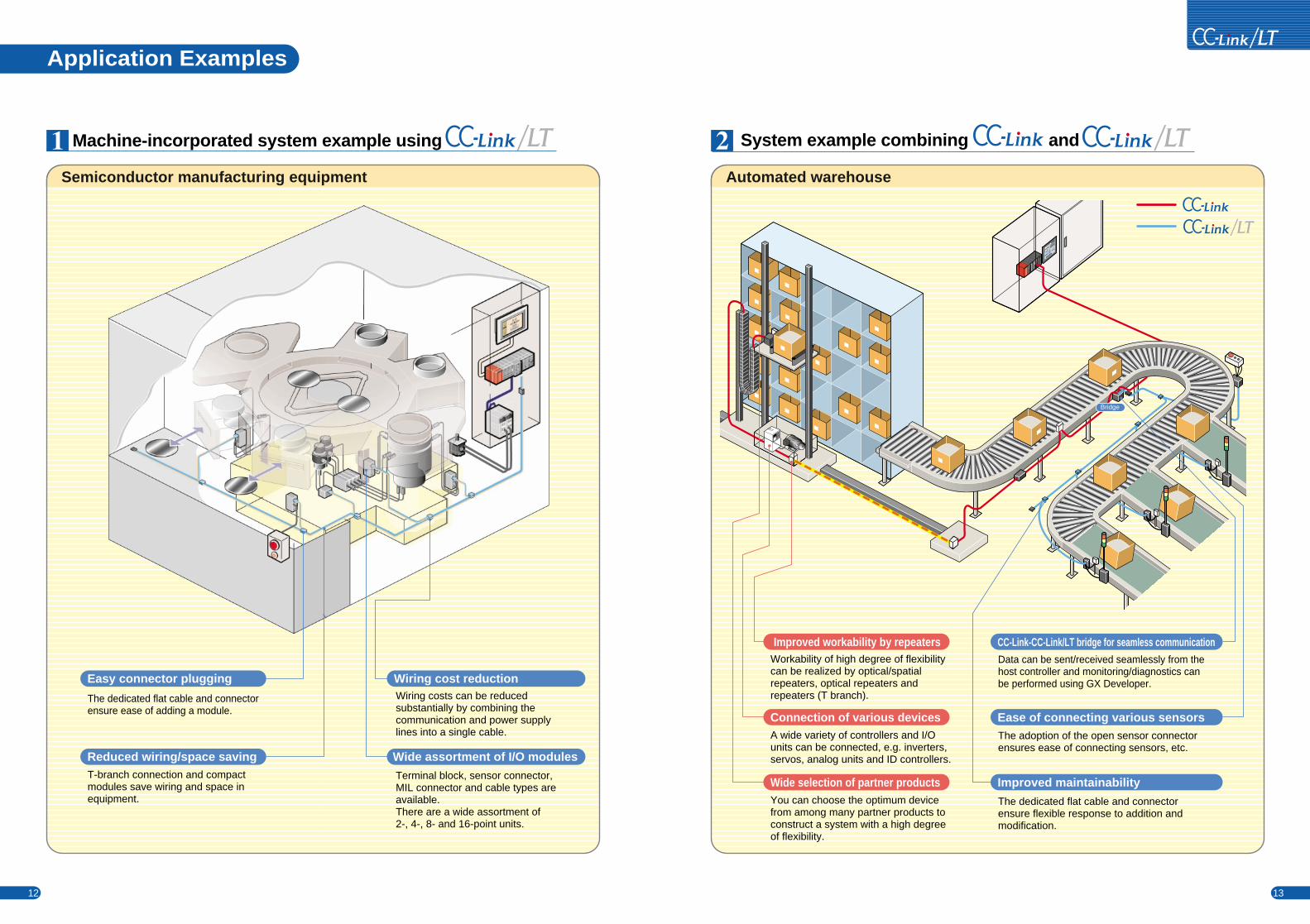
Application Examples
System example combining and
Semiconductor manufacturing equipment Automated warehouse
Machine-incorporated system example using
12 13
Improved maintainability
Ease of connecting various sensors
CC-Link-CC-Link/LT bridge for seamless communicationData can be sent/received seamlessly from the host controller and monitoring/diagnostics can be performed using GX Developer.
The adoption of the open sensor connector ensures ease of connecting sensors, etc.
The dedicated flat cable and connector ensure flexible response to addition and modification.
Terminal block, sensor connector,MIL connector and cable types areavailable. There are a wide assortment of 2-, 4-, 8- and 16-point units.
Wiring costs can be reducedsubstantially by combining thecommunication and power supply lines into a single cable.
T-branch connection and compactmodules save wiring and space in equipment.
Wiring cost reduction
Wide assortment of I/O modules
The dedicated flat cable and connectorensure ease of adding a module.
Easy connector plugging
Reduced wiring/space saving
Bridge
You can choose the optimum devicefrom among many partner products toconstruct a system with a high degreeof flexibility.
Wide selection of partner products
A wide variety of controllers and I/Ounits can be connected, e.g. inverters, servos, analog units and ID controllers.
Workability of high degree of flexibilitycan be realized by optical/spatialrepeaters, optical repeaters andrepeaters (T branch).
Connection of various devices
Improved workability by repeaters
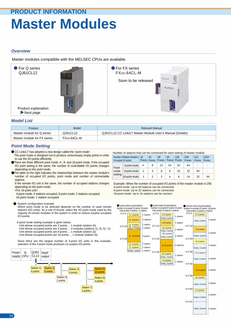
Master Modules
Overview
Master modules compatible with the MELSEC CPUs are available.
For Q seriesQJ61CL12
For FX seriesFX2N-64CL-M
Soon to be released
Product
Master module for Q series
Master module for FX series
QJ61CL12
FX2N-64CL-M
Model List
Point Mode Setting
Part Names and Settings
Model
QJ61CL12 CC-Link/LT Master Module User’s Manual (Details)
Relevant Manual
Product explanation Next page
QJ61CL12
Operation setting switch setting details
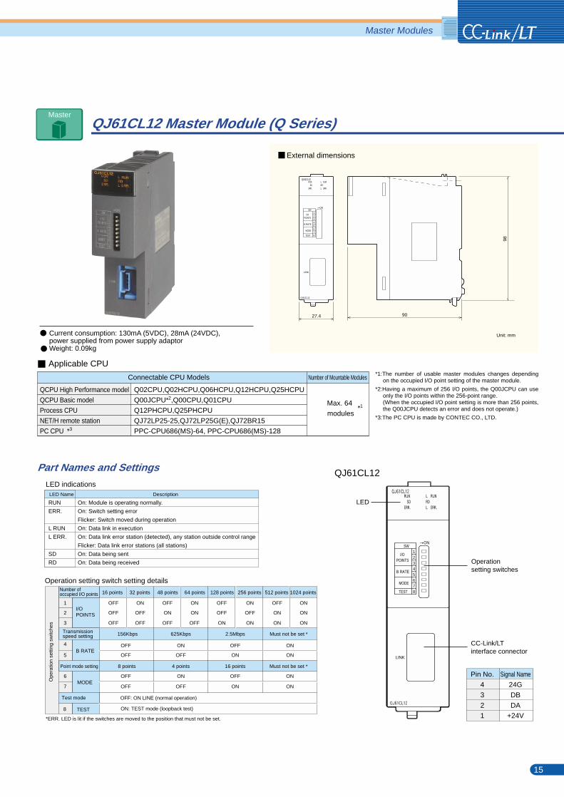
QJ61CL12 Master Module (Q Series)
LED indicationsLED Name Description
RUN
ERR.
L RUN
L ERR.
SD
RD
On: Module is operating normally.
On: Switch setting error
Flicker: Switch moved during operation
On: Data link in execution
On: Data link error station (detected), any station outside control range
Flicker: Data link error stations (all stations)
On: Data being sent
On: Data being received
Unit: mm
Master ModulesPRODUCT INFORMATION
QCPU High Performance model
QCPU Basic model
Process CPU
NET/H remote station
PC CPU *3
Connectable CPU Models Number of Mountable Modules
Max. 64
modules
Q02CPU,Q02HCPU,Q06HCPU,Q12HCPU,Q25HCPU
Q00JCPU*2,Q00CPU,Q01CPU
Q12PHCPU,Q25PHCPU
QJ72LP25-25,QJ72LP25G(E),QJ72BR15
PPC-CPU686(MS)-64, PPC-CPU686(MS)-128
*1:The number of usable master modules changes depending on the occupied I/O point setting of the master module.
*2:Having a maximum of 256 I/O points, the Q00JCPU can use only the I/O points within the 256-point range.(When the occupied I/O point setting is more than 256 points, the Q00JCPU detects an error and does not operate.)
*3:The PC CPU is made by CONTEC CO., LTD.
*1
LED
Operationsetting switches
CC-Link/LTinterface connector
LINK
ON
TEST
MODE
B RATE
87654321
SW
POINTSI/O
27.4
QJ61CL12
LINK
ON
QJ61CL12
TEST
MODE
B RATE
87654321
SW
90
98
POINTSI/O
Number of Master Module’s Occupied I/O points
Number of stations that can be connected for each setting of master module
16Points
32Points
48Points
64Points
128Points
256Points
512Points
1024Points
4-point mode 4 8 12 16 32 64 - -
16-point mode
2 4 6 8 16 32 64 -Pointmodesetting
8-point mode
1 2
3 4 8 16 32 64
CC-Link/LT has adopted a new design called the "point mode". The point mode is designed not to produce unnecessary empty points in order
to use the I/O points efficiently. There are three different point mode, 4-, 8- and 16-point mode. If the occupied
I/O point setting is the same, the number of controllable I/O points changes depending on the point mode.
The table on the right indicates the relationships between the master module’s number of occupied I/O points, point mode and number of connectable stations.If the remote I/O unit is the same, the number of occupied stations changes depending on the point mode.
<For 16-point unit> 4-point mode: 4 stations occupied, 8-point mode: 2 stations occupied, 16-point mode: 1 station occupied
Example: When the number of occupied I/O points of the master module is 2564-point mode: Up to 64 stations can be connected.8-point mode: Up to 32 stations can be connected.16-point mode: Up to 16 stations can be connect
X /Y 0
X /Y 10
X /Y 20
X /Y 30
X /Y 0
X /Y 10
X /Y 20
1) 4 points
2) 8 points
3) 4 points
4) 2 points
5) 16 points
6) 4 points
7) 4 points
1) 4 points
2) 8 points
3) 4 points4) 2 points
5) 16 points
6) 4 points
7) 4 points
1 station
2 stations
1 station
1 station
4 points
1 station
1 station
1 station
Empty, 4 points
Empty, 4 points
Empty, 6 points
Empty, 4 points
Empty, 4 points
Empty, 2 points
Empty, 4 points
4-point mode (4 points/station)Number of occupied I/O points: 48 points
Total number of stations: 12 stations Total number of stations: 8 stations
8-point mode (8 points/station)Number of occupied I/O points: 64 points
Powersupply
QCPU
QJ61CL12
Input/output
Station 1)4 points
Station 3)4 points
Station 4)2 points
Station 5)16 points
Station 6)4 points
Station 7)4 points
16 points 32 points 48 points 64 points 128 points 256 points 512 points 1024 points
1
2
3
OFF
OFF
OFF
ON
OFF
OFF
ON
OFF
OFF
ON
ON
OFF ON
OFF
OFF ON
OFF
ON
OFF
ON
ON ON
ON
ONI/O POINTS
Transmissionspeed setting
4
5
*ERR. LED is lit if the switches are moved to the position that must not be set.
MODE6
7
625Kbps
OFF
ON
4 points
OFF
ON
2.5Mbps
OFF
ON
16 points
OFF
ON
Must not be set *
*
ON
ON
Must not be set
ON
ON
Number of occupied I/O points
B RATE
Point mode setting
TEST8
Test mode
156Kbps
OFF
OFF
8 points
OFF
OFF
OFF: ON LINE (normal operation)
14 15
System configuration exampleWhich point mode to be selected depends on the number of used remote stations (I/O units). As a rule of thumb, select the I/O point mode used by the majority of remote modules in the system in order to reduce surplus occupied I/O points.
A point mode setting example is given below. Unit whose occupied points are 2 points ... 1 module (station 4)) Unit whose occupied points are 4 points ... 4 modules (stations 1), 3), 6), 7)) Unit whose occupied points are 8 points ... 1 module (station 2)) Unit whose occupied points are 16 points ... 1 module (station 5))
Since there are the largest number of 4-point I/O units in this example, selection of the 4-point mode produces no surplus I/O points.
X /Y 0
X /Y 10
X /Y 20
X /Y 30
X /Y 40
X /Y 50
X /Y 60
X /Y70
1) 4 points
2) 8 points
3) 4 points
4) 2 points
5) 16 points
6) 4 points
7) 4 points
Empty, 12 points
Empty, 8 points
Empty, 12 points
Empty, 14 points
Empty, 12 points
Empty, 12 points
Empty, 16 points
Total number of stations: 8 stations
16-point mode (16 points/station)Number of occupied I/O points: 128 points
1 station
2 stations
1 station
1 station
1 station
1 station
1 station
1 station
1 station
1 station
1 station
1 station
1 station
1 station
1 station
Pin No.
4
3
2
1
Signal Name
24G
DB
DA
+24V
Station 2)8 points
Ope
ratio
n se
tting
sw
itche
s
ON: TEST mode (loopback test)
External dimensions
Applicable CPU
Current consumption: 130mA (5VDC), 28mA (24VDC), power supplied from power supply adaptorWeight: 0.09kg
Master
Master Modules
Overview
Master modules compatible with the MELSEC CPUs are available.
For Q seriesQJ61CL12
For FX seriesFX2N-64CL-M
Soon to be released
Product
Master module for Q series
Master module for FX series
QJ61CL12
FX2N-64CL-M
Model List
Point Mode Setting
Part Names and Settings
Model
QJ61CL12 CC-Link/LT Master Module User’s Manual (Details)
Relevant Manual
Product explanation Next page
QJ61CL12
Operation setting switch setting details
QJ61CL12 Master Module (Q Series)
LED indicationsLED Name Description
RUN
ERR.
L RUN
L ERR.
SD
RD
On: Module is operating normally.
On: Switch setting error
Flicker: Switch moved during operation
On: Data link in execution
On: Data link error station (detected), any station outside control range
Flicker: Data link error stations (all stations)
On: Data being sent
On: Data being received
Unit: mm
Master ModulesPRODUCT INFORMATION
QCPU High Performance model
QCPU Basic model
Process CPU
NET/H remote station
PC CPU *3
Connectable CPU Models Number of Mountable Modules
Max. 64
modules
Q02CPU,Q02HCPU,Q06HCPU,Q12HCPU,Q25HCPU
Q00JCPU*2,Q00CPU,Q01CPU
Q12PHCPU,Q25PHCPU
QJ72LP25-25,QJ72LP25G(E),QJ72BR15
PPC-CPU686(MS)-64, PPC-CPU686(MS)-128
*1:The number of usable master modules changes depending on the occupied I/O point setting of the master module.
*2:Having a maximum of 256 I/O points, the Q00JCPU can use only the I/O points within the 256-point range.(When the occupied I/O point setting is more than 256 points, the Q00JCPU detects an error and does not operate.)
*3:The PC CPU is made by CONTEC CO., LTD.
*1
LED
Operationsetting switches
CC-Link/LTinterface connector
LINK
ON
TEST
MODE
B RATE
87654321
SW
POINTSI/O
27.4
QJ61CL12
LINK
ON
QJ61CL12
TEST
MODE
B RATE
87654321
SW
90
98
POINTSI/O
Number of Master Module’s Occupied I/O points
Number of stations that can be connected for each setting of master module
16Points
32Points
48Points
64Points
128Points
256Points
512Points
1024Points
4-point mode 4 8 12 16 32 64 - -
16-point mode
2 4 6 8 16 32 64 -Pointmodesetting
8-point mode
1 2
3 4 8 16 32 64
CC-Link/LT has adopted a new design called the "point mode". The point mode is designed not to produce unnecessary empty points in order
to use the I/O points efficiently. There are three different point mode, 4-, 8- and 16-point mode. If the occupied
I/O point setting is the same, the number of controllable I/O points changes depending on the point mode.
The table on the right indicates the relationships between the master module’s number of occupied I/O points, point mode and number of connectable stations.If the remote I/O unit is the same, the number of occupied stations changes depending on the point mode.
<For 16-point unit> 4-point mode: 4 stations occupied, 8-point mode: 2 stations occupied, 16-point mode: 1 station occupied
Example: When the number of occupied I/O points of the master module is 2564-point mode: Up to 64 stations can be connected.8-point mode: Up to 32 stations can be connected.16-point mode: Up to 16 stations can be connect
X /Y 0
X /Y 10
X /Y 20
X /Y 30
X /Y 0
X /Y 10
X /Y 20
1) 4 points
2) 8 points
3) 4 points
4) 2 points
5) 16 points
6) 4 points
7) 4 points
1) 4 points
2) 8 points
3) 4 points4) 2 points
5) 16 points
6) 4 points
7) 4 points
1 station
2 stations
1 station
1 station
4 points
1 station
1 station
1 station
Empty, 4 points
Empty, 4 points
Empty, 6 points
Empty, 4 points
Empty, 4 points
Empty, 2 points
Empty, 4 points
4-point mode (4 points/station)Number of occupied I/O points: 48 points
Total number of stations: 12 stations Total number of stations: 8 stations
8-point mode (8 points/station)Number of occupied I/O points: 64 points
Powersupply
QCPU
QJ61CL12
Input/output
Station 1)4 points
Station 3)4 points
Station 4)2 points
Station 5)16 points
Station 6)4 points
Station 7)4 points
16 points 32 points 48 points 64 points 128 points 256 points 512 points 1024 points
1
2
3
OFF
OFF
OFF
ON
OFF
OFF
ON
OFF
OFF
ON
ON
OFF ON
OFF
OFF ON
OFF
ON
OFF
ON
ON ON
ON
ONI/O POINTS
Transmissionspeed setting
4
5
*ERR. LED is lit if the switches are moved to the position that must not be set.
MODE6
7
625Kbps
OFF
ON
4 points
OFF
ON
2.5Mbps
OFF
ON
16 points
OFF
ON
Must not be set *
*
ON
ON
Must not be set
ON
ON
Number of occupied I/O points
B RATE
Point mode setting
TEST8
Test mode
156Kbps
OFF
OFF
8 points
OFF
OFF
OFF: ON LINE (normal operation)
14 15
System configuration exampleWhich point mode to be selected depends on the number of used remote stations (I/O units). As a rule of thumb, select the I/O point mode used by the majority of remote modules in the system in order to reduce surplus occupied I/O points.
A point mode setting example is given below. Unit whose occupied points are 2 points ... 1 module (station 4)) Unit whose occupied points are 4 points ... 4 modules (stations 1), 3), 6), 7)) Unit whose occupied points are 8 points ... 1 module (station 2)) Unit whose occupied points are 16 points ... 1 module (station 5))
Since there are the largest number of 4-point I/O units in this example, selection of the 4-point mode produces no surplus I/O points.
X /Y 0
X /Y 10
X /Y 20
X /Y 30
X /Y 40
X /Y 50
X /Y 60
X /Y70
1) 4 points
2) 8 points
3) 4 points
4) 2 points
5) 16 points
6) 4 points
7) 4 points
Empty, 12 points
Empty, 8 points
Empty, 12 points
Empty, 14 points
Empty, 12 points
Empty, 12 points
Empty, 16 points
Total number of stations: 8 stations
16-point mode (16 points/station)Number of occupied I/O points: 128 points
1 station
2 stations
1 station
1 station
1 station
1 station
1 station
1 station
1 station
1 station
1 station
1 station
1 station
1 station
1 station
Pin No.
4
3
2
1
Signal Name
24G
DB
DA
+24V
Station 2)8 points
Ope
ratio
n se
tting
sw
itche
s
ON: TEST mode (loopback test)
External dimensions
Applicable CPU
Current consumption: 130mA (5VDC), 28mA (24VDC), power supplied from power supply adaptorWeight: 0.09kg
Master
Remote I/O Modules
Remote I/O Modules
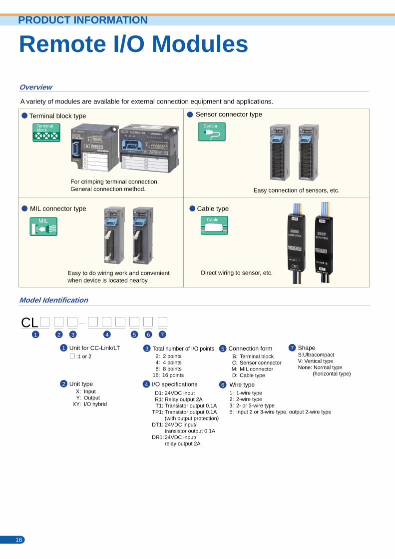
Overview
A variety of modules are available for external connection equipment and applications.
Model Identification
Terminal block type Sensor connector type
Cable typeMIL connector type
For crimping terminal connection.General connection method. Easy connection of sensors, etc.
Direct wiring to sensor, etc.Easy to do wiring work and convenientwhen device is located nearby.
Terminalblock
Sensor
MIL
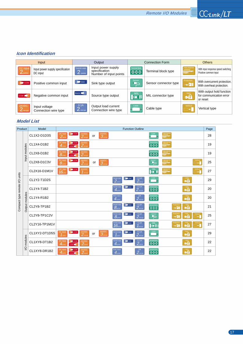
Icon Identification
Input
Input power supply specificationDC input
Positive common input
Negative common input
Input voltageConnection wire type
Input power supplyspecificationNumber of input points
Terminal block type
Sensor connector type
MIL connector type
Cable type
With overcurrent protection.With overheat protection.
With input response speed switchingPositive common input
With output hold functionfor communication erroror reset
Vertical type
Sink type output
Source type output
Output load currentConnection wire type
Output Connection Form Others
CL1 2 3 4 5 6
Connection formB: Terminal blockC: Sensor connectorM: MIL connectorD: Cable type
5
6
7
Wire type1: 1-wire type2: 2-wire type3: 2- or 3-wire type5: Input 2 or 3-wire type, output 2-wire type
ShapeS:UltracompactV: Vertical typeNone: Normal type (horizontal type)
7Unit for CC-Link/LT:1 or 2
X: InputY: Output
XY: I/O hybrid
1
2 Unit type
2: 2 points 4: 4 points 8: 8 points16: 16 points
I/O specificationsD1: 24VDC inputR1: Relay output 2AT1: Transistor output 0.1A
TP1: Transistor output 0.1A (with output protection)DT1: 24VDC input/
transistor output 0.1ADR1:24VDC input/
relay output 2A
3
4
Total number of I/O points
Transistor output
points2DC input
points2Terminal block
Vertical
Vertical
Vertical
Vertical
Vertical
Sensor
MIL
Protection
Protection
Protection
Protection
PRODUCT INFORMATION
+COM
-COM
+COM
+COM
-COM
+COM
+COM
+COM
-COM
+COM
+COM
-COM
+COM
-COM
Sink
Source
Product
CL1X2-D1D3S
CL1X4-D1B2
CL2X8-D1B2
CL2X8-D1C3V
CL2X16-D1M1V
CL1Y2-T1D2S
CL1Y4-T1B2
CL1Y4-R1B2
CL2Y8-TP1B2
CL2Y8-TP1C2V
CL2Y16-TP1M1V
CL1XY2-DT1D5S
CL1XY8-DT1B2
CL1XY8-DR1B2
28
19
19
25
27
29
20
20
21
25
27
29
22
22
Function Outline Page
Transistor output
points2
points8
DC input
points2DC input
points4DC input
points8DC input
points8
2
DC input
point1DC input
points4DC input
points4
points2
-wire type2Transistor output
points8Transistor output
points4Transistor output
point1Transistor output
points4Relay output
0.1A
-wire type20.1A
-wire type20.1A
-wire type20.1A
-wire type20.1A
2A
-wire type20.1A
-wire type2
points4Transistor output
points4Relay output
points20.1A
2A
Terminal block
Terminal block
Terminal block
Terminal block
Terminal block
Terminal block
Terminal block
Sensor
Sensor
MIL
MIL
Model List
Model
DC input
points16Sink
Sink
Sink
Sink
points16Transistor output
-wire type10.1ASink
Sink
Sink
-wire type224VDC
-wire type224VDC
-wire type224VDC
-wire type224VDC
-wire type224VDC
-wire type324VDC
-wire type324VDC
-wire type124VDC
-wire type224VDC
points224VDC
points224VDC
Cable
Cable
Cable
Cable
Cable
or
-wire type324VDC
or
or
Hold
Hold
Hold
Hold
Hold
Hold
Hold
Hold
Hold
Hold
Com
pact
type
rem
ote
I/O u
nits
Inpu
t mod
ules
Out
put m
odul
esI/O
mod
ules
16 17
Input response switching
Input response switching
Input response switching
Input response switching
Input response switching
Input response switching
Remote I/O Modules
Remote I/O Modules
Overview
A variety of modules are available for external connection equipment and applications.
Model Identification
Terminal block type Sensor connector type
Cable typeMIL connector type
For crimping terminal connection.General connection method. Easy connection of sensors, etc.
Direct wiring to sensor, etc.Easy to do wiring work and convenientwhen device is located nearby.
Terminalblock
Sensor
MIL
Icon Identification
Input
Input power supply specificationDC input
Positive common input
Negative common input
Input voltageConnection wire type
Input power supplyspecificationNumber of input points
Terminal block type
Sensor connector type
MIL connector type
Cable type
With overcurrent protection.With overheat protection.
With input response speed switchingPositive common input
With output hold functionfor communication erroror reset
Vertical type
Sink type output
Source type output
Output load currentConnection wire type
Output Connection Form Others
CL1 2 3 4 5 6
Connection formB: Terminal blockC: Sensor connectorM: MIL connectorD: Cable type
5
6
7
Wire type1: 1-wire type2: 2-wire type3: 2- or 3-wire type5: Input 2 or 3-wire type, output 2-wire type
ShapeS:UltracompactV: Vertical typeNone: Normal type (horizontal type)
7Unit for CC-Link/LT:1 or 2
X: InputY: Output
XY: I/O hybrid
1
2 Unit type
2: 2 points 4: 4 points 8: 8 points16: 16 points
I/O specificationsD1: 24VDC inputR1: Relay output 2AT1: Transistor output 0.1A
TP1: Transistor output 0.1A (with output protection)DT1: 24VDC input/
transistor output 0.1ADR1:24VDC input/
relay output 2A
3
4
Total number of I/O points
Transistor output
points2DC input
points2Terminal block
Vertical
Vertical
Vertical
Vertical
Vertical
Sensor
MIL
Protection
Protection
Protection
Protection
PRODUCT INFORMATION
+COM
-COM
+COM
+COM
-COM
+COM
+COM
+COM
-COM
+COM
+COM
-COM
+COM
-COM
Sink
Source
Product
CL1X2-D1D3S
CL1X4-D1B2
CL2X8-D1B2
CL2X8-D1C3V
CL2X16-D1M1V
CL1Y2-T1D2S
CL1Y4-T1B2
CL1Y4-R1B2
CL2Y8-TP1B2
CL2Y8-TP1C2V
CL2Y16-TP1M1V
CL1XY2-DT1D5S
CL1XY8-DT1B2
CL1XY8-DR1B2
28
19
19
25
27
29
20
20
21
25
27
29
22
22
Function Outline Page
Transistor output
points2
points8
DC input
points2DC input
points4DC input
points8DC input
points8
2
DC input
point1DC input
points4DC input
points4
points2
-wire type2Transistor output
points8Transistor output
points4Transistor output
point1Transistor output
points4Relay output
0.1A
-wire type20.1A
-wire type20.1A
-wire type20.1A
-wire type20.1A
2A
-wire type20.1A
-wire type2
points4Transistor output
points4Relay output
points20.1A
2A
Terminal block
Terminal block
Terminal block
Terminal block
Terminal block
Terminal block
Terminal block
Sensor
Sensor
MIL
MIL
Model List
Model
DC input
points16Sink
Sink
Sink
Sink
points16Transistor output
-wire type10.1ASink
Sink
Sink
-wire type224VDC
-wire type224VDC
-wire type224VDC
-wire type224VDC
-wire type224VDC
-wire type324VDC
-wire type324VDC
-wire type124VDC
-wire type224VDC
points224VDC
points224VDC
Cable
Cable
Cable
Cable
Cable
or
-wire type324VDC
or
or
Hold
Hold
Hold
Hold
Hold
Hold
Hold
Hold
Hold
Hold
Com
pact
type
rem
ote
I/O u
nits
Inpu
t mod
ules
Out
put m
odul
esI/O
mod
ules
16 17
Input response switching
Input response switching
Input response switching
Input response switching
Input response switching
Input response switching
Remote I/O Modules
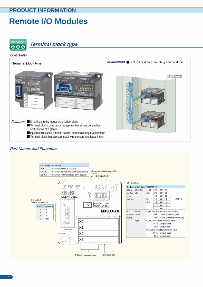
Terminal block type
Small size in the industry’s smallest classTerminal block cover has a nameplate that shows connectiondestinations at a glanceInput modules used either as positive common or negative commonTerminal block that can connect 2-wire sensors and loads intact
DIN rail or direct mounting can be done.
Overview
Part Names and Functions
Features
Installation
Terminal block type
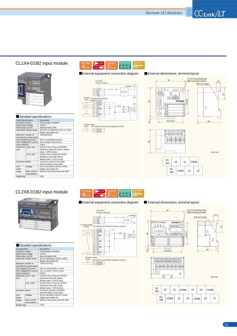
CL1X4-D1B2 input module
External dimensions, terminal layoutExternal equipment connection diagram
External dimensions, terminal layoutExternal equipment connection diagram
CL2X8-D1B2 input module
18 19
OFF ON
ON OFF
Input SpecificationsInsulation systemRated input voltageRated input currentOperating voltage range
Maximum number ofsimultaneous input pointsON voltage/ON currentOFF voltage/OFF currentInput resistanceResponsetime
Common system
Unitpowersupply
Weight (kg)
Voltage
Max. currentconsumption
DescriptionPhotocoupler insulation24VDCApproximately 4mA20.4VDC to 28.8VDC(-15% to +20%)Ripple ratio within 5%100%(DC24V)
19V or more/3mA or more11V or less/1.7mA or less5.6k0.5ms/1.5ms or less (at 24VDC)[Selected using DIP switch, defaultvalue = OFF/1.5ms]0.5ms/1.5ms or less (at 24VDC)[Selected using DIP switch, default value = OFF/1.5ms]4 points/1 common (2 points) (terminal block 2-wire type)20.4 to 28.8VDC(-15% to +20%)Ripple ratio within 5%35mA or less (when all points ON)
0.06
OFF ON
ON OFF
SpecificationsInsulation systemRated input voltageRated input currentOperating voltage range
Maximum number ofsimultaneous input pointsON voltage/ON currentOFF voltage/OFF currentInput resistanceResponsetime
Common system
Unitpowersupply
Weight (kg)
Voltage
Max. currentconsumption
DescriptionPhotocoupler insulation24VDCApproximately 4mA20.4 to 28.8VDC(-15% to +20%)Ripple ratio within 5%100%(24VDC)
19V or more/3mA or more11V or less/1.7mA or less5.6k0.5ms/1.5ms or less (at 24VDC)[Selected using DIP switch,default value = OFF/1.5ms]0.5ms/1.5ms or less (at 24VDC)[Selected using DIP switch, default value = OFF/1.5ms]8 points/1 common (4 points)(terminal block 2-wire type)20.4 to 28.8VDC(-15% to +20%)Ripple ratio within 5%40mA or less (when all points ON)
0.09
Unit: mm
Unit: mm
+COM
-COM
+COM
-COM
Terminal block
DC input
points4 -wire type224VDC Terminal block Input response
switching
-wire type224VDC Terminal block Input response
switchingDC input
points8
Detailed specifications
Detailed specifications
LED Name
PW
L RUN
L ERR.
I/O operation indicator LEDsON: LitOFF: Extinguished
DIN rail mounting hook Terminal block
CC-Link/LTinterface connector
Operation
Lit when power is supplied.
Lit when normal operation is performed.
Lit when communication error occurs.
Pin No.
4
3
2
1
Signal Name
24G
DB
DA
+24V
Remote I/O ModulesPRODUCT INFORMATION
DIP switches
Setting
Station
number
setting
switches
I/O
operation
setting
Switch Name
STATION
NO.
0.5ms
1.5ms
Description
Tenth
digit
Unit
digit
Input unit: Response speed setting
OFF: 1.5ms (standard type)
ON: 0.5ms (fast response type)
Output unit : Hold function valid
OFF: Output clear
ON: Output held
I/O hybrid unit: Hold function valid
OFF: Output clear
ON: Output held
40
20
10
8
4
2
1
ON : 40
ON : 20
ON : 10
ON : 8
ON : 4
ON : 2
ON : 1
HLD
OFF : 0
DC24A
DC24B
X0
COMB
X1
X2 X3
COMB
X0 X4X1 COMBDC24A
R
12345
X0COMBX1X2COMBX3X4COMBX5X6COMBX7
89
101112
67
I/O interface terminal block (positive common)
I/O interface terminal block (negative common)
CC-Link/LTinterface connector
1234
+24VDA
24GDB
DC DC
Insulation
DC24A
1314
DC24B
I/O power supply
12 DC24B
DC24A
CC-Link/LTinterface connector
CL2X8-D1B2
IN
PW L ERR.L RUN
ON
0 1 2 3 4 5 6 7
LINK/PW
X5
X4
X1
X0
X2
X3
X6
X7
10
40
2- 4.5 mounting hole (M4 mounting screw)
22
DIN rail center
DIN rail center
4.5
49
64
24VDC
I/O power supply24VDC
0 1 2 3PW L RUN L ERR.
LINK/PW
CL1X4-D1B2ON
IN
X1
X0
X2
X3
494.
540
40
10
X1
X0
X2
X3
DC24ADC24BX0COMB
1234
X1X2COMBX3
+24VDADB24G
1234
5678
DC24ADC24B
12
R
R
DC DC
DC input24VDC
I/O power supply24VDC
Insulation
I/O interface terminal block(positive common)
I/O interface terminal block (negative common)
X5 COMB
COMB COMBX2 X3 X6 X7DC24B
2- 4.5 mounting hole (M4 mounting screw)
50
22
41
0.4
41.5 0.4
41
0.2
55.5 0.4
402010 8 4 2 1 0.5ms1.5msSTATION NO.
0 1 2 3PW L RUN L ERR.
LINK/PW
CL1X4-D1B2ON
IN 402010 8 4 2 1 0.5ms1.5msSTATION NO.
40 20 10 8 4 2 1 0.2ms1.5msSTATION NO.
R
2- 4.5 mounting hole (M4 mounting screw)
Remote I/O Modules
Terminal block type
Small size in the industry’s smallest classTerminal block cover has a nameplate that shows connectiondestinations at a glanceInput modules used either as positive common or negative commonTerminal block that can connect 2-wire sensors and loads intact
DIN rail or direct mounting can be done.
Overview
Part Names and Functions
Features
Installation
Terminal block type
CL1X4-D1B2 input module
External dimensions, terminal layoutExternal equipment connection diagram
External dimensions, terminal layoutExternal equipment connection diagram
CL2X8-D1B2 input module
18 19
OFF ON
ON OFF
Input SpecificationsInsulation systemRated input voltageRated input currentOperating voltage range
Maximum number ofsimultaneous input pointsON voltage/ON currentOFF voltage/OFF currentInput resistanceResponsetime
Common system
Unitpowersupply
Weight (kg)
Voltage
Max. currentconsumption
DescriptionPhotocoupler insulation24VDCApproximately 4mA20.4VDC to 28.8VDC(-15% to +20%)Ripple ratio within 5%100%(DC24V)
19V or more/3mA or more11V or less/1.7mA or less5.6k0.5ms/1.5ms or less (at 24VDC)[Selected using DIP switch, defaultvalue = OFF/1.5ms]0.5ms/1.5ms or less (at 24VDC)[Selected using DIP switch, default value = OFF/1.5ms]4 points/1 common (2 points) (terminal block 2-wire type)20.4 to 28.8VDC(-15% to +20%)Ripple ratio within 5%35mA or less (when all points ON)
0.06
OFF ON
ON OFF
SpecificationsInsulation systemRated input voltageRated input currentOperating voltage range
Maximum number ofsimultaneous input pointsON voltage/ON currentOFF voltage/OFF currentInput resistanceResponsetime
Common system
Unitpowersupply
Weight (kg)
Voltage
Max. currentconsumption
DescriptionPhotocoupler insulation24VDCApproximately 4mA20.4 to 28.8VDC(-15% to +20%)Ripple ratio within 5%100%(24VDC)
19V or more/3mA or more11V or less/1.7mA or less5.6k0.5ms/1.5ms or less (at 24VDC)[Selected using DIP switch,default value = OFF/1.5ms]0.5ms/1.5ms or less (at 24VDC)[Selected using DIP switch, default value = OFF/1.5ms]8 points/1 common (4 points)(terminal block 2-wire type)20.4 to 28.8VDC(-15% to +20%)Ripple ratio within 5%40mA or less (when all points ON)
0.09
Unit: mm
Unit: mm
+COM
-COM
+COM
-COM
Terminal block
DC input
points4 -wire type224VDC Terminal block Input response
switching
-wire type224VDC Terminal block Input response
switchingDC input
points8
Detailed specifications
Detailed specifications
LED Name
PW
L RUN
L ERR.
I/O operation indicator LEDsON: LitOFF: Extinguished
DIN rail mounting hook Terminal block
CC-Link/LTinterface connector
Operation
Lit when power is supplied.
Lit when normal operation is performed.
Lit when communication error occurs.
Pin No.
4
3
2
1
Signal Name
24G
DB
DA
+24V
Remote I/O ModulesPRODUCT INFORMATION
DIP switches
Setting
Station
number
setting
switches
I/O
operation
setting
Switch Name
STATION
NO.
0.5ms
1.5ms
Description
Tenth
digit
Unit
digit
Input unit: Response speed setting
OFF: 1.5ms (standard type)
ON: 0.5ms (fast response type)
Output unit : Hold function valid
OFF: Output clear
ON: Output held
I/O hybrid unit: Hold function valid
OFF: Output clear
ON: Output held
40
20
10
8
4
2
1
ON : 40
ON : 20
ON : 10
ON : 8
ON : 4
ON : 2
ON : 1
HLD
OFF : 0
DC24A
DC24B
X0
COMB
X1
X2 X3
COMB
X0 X4X1 COMBDC24A
R
12345
X0COMBX1X2COMBX3X4COMBX5X6COMBX7
89
101112
67
I/O interface terminal block (positive common)
I/O interface terminal block (negative common)
CC-Link/LTinterface connector
1234
+24VDA
24GDB
DC DC
Insulation
DC24A
1314
DC24B
I/O power supply
12 DC24B
DC24A
CC-Link/LTinterface connector
CL2X8-D1B2
IN
PW L ERR.L RUN
ON
0 1 2 3 4 5 6 7
LINK/PW
X5
X4
X1
X0
X2
X3
X6
X7
10
40
2- 4.5 mounting hole (M4 mounting screw)
22
DIN rail center
DIN rail center
4.5
49
64
24VDC
I/O power supply24VDC
0 1 2 3PW L RUN L ERR.
LINK/PW
CL1X4-D1B2ON
IN
X1
X0
X2
X3
494.
540
40
10
X1
X0
X2
X3
DC24ADC24BX0COMB
1234
X1X2COMBX3
+24VDADB24G
1234
5678
DC24ADC24B
12
R
R
DC DC
DC input24VDC
I/O power supply24VDC
Insulation
I/O interface terminal block(positive common)
I/O interface terminal block (negative common)
X5 COMB
COMB COMBX2 X3 X6 X7DC24B
2- 4.5 mounting hole (M4 mounting screw)
50
22
41
0.4
41.5 0.4
41
0.2
55.5 0.4
402010 8 4 2 1 0.5ms1.5msSTATION NO.
0 1 2 3PW L RUN L ERR.
LINK/PW
CL1X4-D1B2ON
IN 402010 8 4 2 1 0.5ms1.5msSTATION NO.
40 20 10 8 4 2 1 0.2ms1.5msSTATION NO.
R
2- 4.5 mounting hole (M4 mounting screw)
External dimensions, terminal layoutExternal equipment connection diagram
External dimensions, terminal layoutExternal equipment connection diagram
External dimensions, terminal layoutExternal equipment connection diagram
Remote I/O Modules
Terminal block type
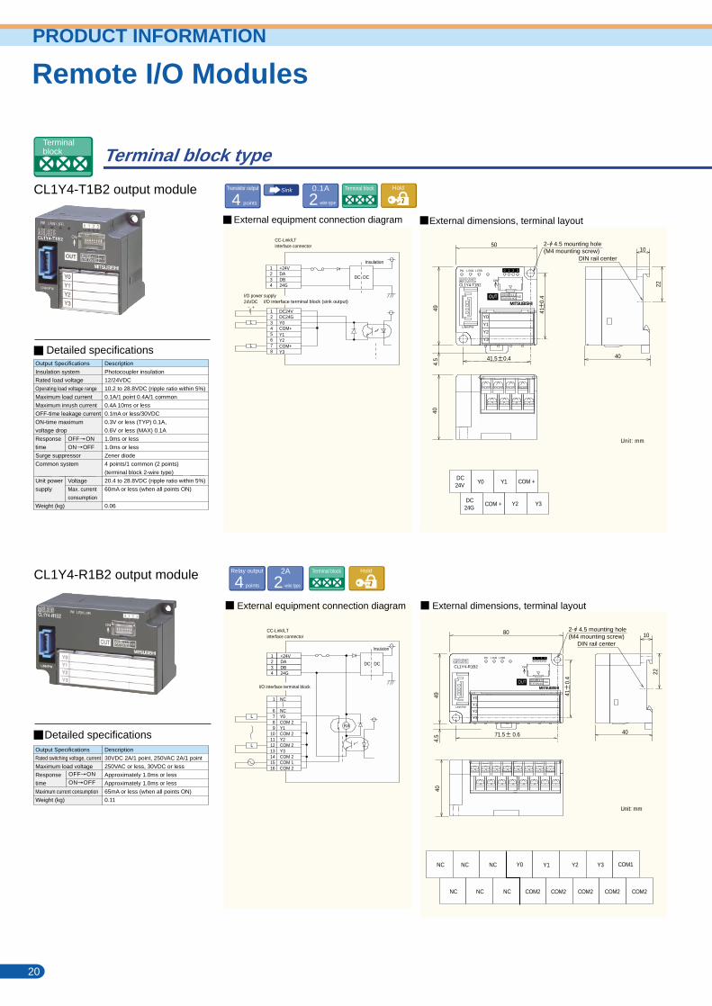
CL1Y4-R1B2 output module
CL1Y4-T1B2 output module CL2Y8-TP1B2 output module
20 21
OFF ON
ON OFF
Output Specifications
Insulation system
Rated load voltage
Operating load voltage range
Maximum load current
Maximum inrush current
OFF-time leakage current
ON-time maximum
voltage drop
Response
time
Surge suppressor
Common system
Unit power
supply
Weight (kg)
Voltage
Max. current
consumption
Description
Photocoupler insulation
12/24VDC
10.2 to 28.8VDC (ripple ratio within 5%)
0.1A/1 point 0.4A/1 common
0.4A 10ms or less
0.1mA or less/30VDC
0.3V or less (TYP) 0.1A,
0.6V or less (MAX) 0.1A
1.0ms or less
1.0ms or less
Zener diode
4 points/1 common (2 points)
(terminal block 2-wire type)
20.4 to 28.8VDC (ripple ratio within 5%)
60mA or less (when all points ON)
0.06
OFF ONON OFF
Output SpecificationsInsulation systemRated load voltageOperating load voltage rangeMaximum load currentMaximum inrush currentOFF-time leakage currentON-time maximum voltage dropResponsetimeSurge suppressorCommon system
Output sectionexternal supplypowerUnit powersupply
Weight (kg)
VoltageCurrent consumptionVoltageMax. currentconsumption
DescriptionPhotocoupler insulation12/24VDC10.2 to 28.8VDC (ripple ratio within 5%)0.1A/1 point 0.8A/1 common0.7A 10ms or less0.1mA or less0.3V or less (TYP) 0.1A, 0.6V or less (MAX) 0.1A0.5ms or less0.5ms or less (resistive load)Zener diode8 points/1 common (4 points)(terminal block 2-wire type)As in load power supply15mA or less(TYP. 24VDC, when all points ON)20.4 to 28.8VDC (ripple ratio within 5%)40mA or less (when all points ON)
0.09
OFF ON
ON OFF
Output Specifications
Rated switching voltage, current
Maximum load voltage
Response
time
Maximum current consumption
Weight (kg)
Description
30VDC 2A/1 point, 250VAC 2A/1 point
250VAC or less, 30VDC or less
Approximately 1.0ms or less
Approximately 1.0ms or less
65mA or less (when all points ON)
0.11
points4Relay output
-wire type22A Terminal block Hold
Detailed specifications
Detailed specifications
Detailed specifications
Remote I/O ModulesPRODUCT INFORMATION
DC24V
DC24G
Y0
COM +
Y1
Y2 Y3
COM +
12345
Y0COM+Y1Y2COM+Y3Y4COM+Y5Y6COM+Y7
89
101112
67
I/O interface terminal block (sink output)Constant-voltage circuit
L
L
DC24V
1314
DC24G
24VDC
Load power supply/output section externalsupply power
CC-Link/LT interface connector
1234
+24VDA
24GDB DC DC
Insulation
Y0 Y1 Y4 Y5 COM +COM +
COM + COM +Y2 Y3 Y6 Y7
DC24V
DC24G
NC NC NC
NC NC NC
Y0 Y1 COM1
COM2COM2COM2COM2COM2
Y2 Y3
LINK/PW
CL1Y4-T1B2
Y1
Y0
Y2
Y3
+24VDADB24G
1234
DC24VDC24GY0COM+
1234
Y1Y2COM+Y3
5678
DC DC
I/O power supply24VDC
L
L
Insulation
+24VDADB24G
1234
I/O interface terminal block
DC DC
Insulation
RA
LINK/PW
CL1Y4-R1B2
80
Y1
Y0
Y2
Y3
CL2Y8-TP1B2PW L ERR.L RUN
ON
HLD40 20 10STATION NO.
Y4Y0
Y5Y1
Y7Y3
Y6Y2
10
64
494.
5
22
40
DIN rail center
CC-Link/LTinterface connector
CC-Link/LTinterface connector
2- 4.5 mounting hole(M4 mounting screw)
DIN rail center
494.
540
40
1050
2- 4.5 mounting hole(M4 mounting screw)
DIN rail center
494.
540
40
10
2- 4.5 mounting hole(M4 mounting screw)
40
41.5 0.455.5 0.4
41
0.2
71.5 0.6
41
0.4
41
0.4
22
Unit: mm
22
Unit: mm
Unit: mm
I/O interface terminal block (sink output)
PW L RUN L ERR.
ON
402010 8 4 2 1HLD
STATION NO.
0 1 2 3
1
6789
10111213141516
NC
NCY0COM 2Y1COM 2Y2COM 2Y3COM 2COM 1COM 2
L
L
PW L RUN L ERR.
ON
402010 8 4 2 1HLD
STATION NO.
SpecificationsApplicablecrimping terminal/wire size
Unit mountingmethod
Applicable DIN rail
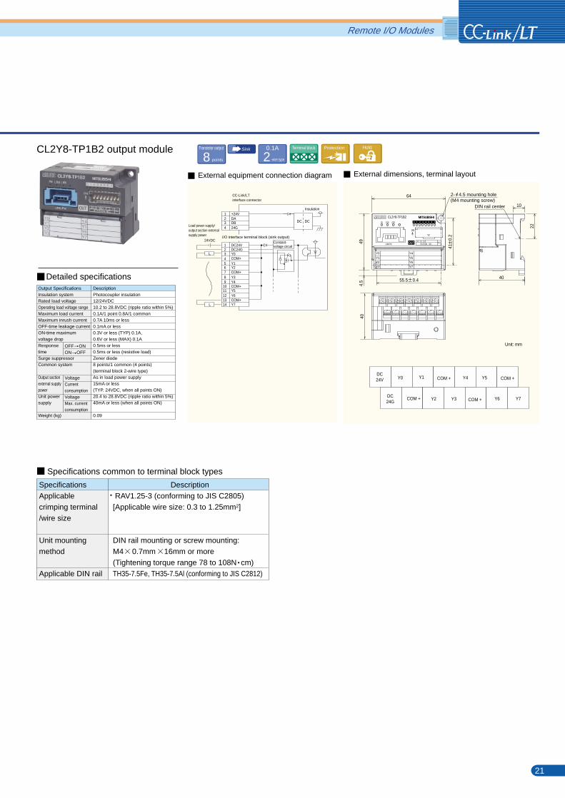
Description RAV1.25-3 (conforming to JIS C2805)[Applicable wire size: 0.3 to 1.25mm2]
DIN rail mounting or screw mounting: M4 0.7mm 16mm or more(Tightening torque range 78 to 108N cm)TH35-7.5Fe, TH35-7.5Al (conforming to JIS C2812)
Specifications common to terminal block types
Transistor output
points4Sink
-wire type20.1A Terminal block Hold
Terminalblock
Transistor output
points8Terminal block Protection Hold
-wire type20.1ASink
External dimensions, terminal layoutExternal equipment connection diagram
External dimensions, terminal layoutExternal equipment connection diagram
External dimensions, terminal layoutExternal equipment connection diagram
Remote I/O Modules
Terminal block type
CL1Y4-R1B2 output module
CL1Y4-T1B2 output module CL2Y8-TP1B2 output module
20 21
OFF ON
ON OFF
Output Specifications
Insulation system
Rated load voltage
Operating load voltage range
Maximum load current
Maximum inrush current
OFF-time leakage current
ON-time maximum
voltage drop
Response
time
Surge suppressor
Common system
Unit power
supply
Weight (kg)
Voltage
Max. current
consumption
Description
Photocoupler insulation
12/24VDC
10.2 to 28.8VDC (ripple ratio within 5%)
0.1A/1 point 0.4A/1 common
0.4A 10ms or less
0.1mA or less/30VDC
0.3V or less (TYP) 0.1A,
0.6V or less (MAX) 0.1A
1.0ms or less
1.0ms or less
Zener diode
4 points/1 common (2 points)
(terminal block 2-wire type)
20.4 to 28.8VDC (ripple ratio within 5%)
60mA or less (when all points ON)
0.06
OFF ONON OFF
Output SpecificationsInsulation systemRated load voltageOperating load voltage rangeMaximum load currentMaximum inrush currentOFF-time leakage currentON-time maximum voltage dropResponsetimeSurge suppressorCommon system
Output sectionexternal supplypowerUnit powersupply
Weight (kg)
VoltageCurrent consumptionVoltageMax. currentconsumption
DescriptionPhotocoupler insulation12/24VDC10.2 to 28.8VDC (ripple ratio within 5%)0.1A/1 point 0.8A/1 common0.7A 10ms or less0.1mA or less0.3V or less (TYP) 0.1A, 0.6V or less (MAX) 0.1A0.5ms or less0.5ms or less (resistive load)Zener diode8 points/1 common (4 points)(terminal block 2-wire type)As in load power supply15mA or less(TYP. 24VDC, when all points ON)20.4 to 28.8VDC (ripple ratio within 5%)40mA or less (when all points ON)
0.09
OFF ON
ON OFF
Output Specifications
Rated switching voltage, current
Maximum load voltage
Response
time
Maximum current consumption
Weight (kg)
Description
30VDC 2A/1 point, 250VAC 2A/1 point
250VAC or less, 30VDC or less
Approximately 1.0ms or less
Approximately 1.0ms or less
65mA or less (when all points ON)
0.11
points4Relay output
-wire type22A Terminal block Hold
Detailed specifications
Detailed specifications
Detailed specifications
Remote I/O ModulesPRODUCT INFORMATION
DC24V
DC24G
Y0
COM +
Y1
Y2 Y3
COM +
12345
Y0COM+Y1Y2COM+Y3Y4COM+Y5Y6COM+Y7
89
101112
67
I/O interface terminal block (sink output)Constant-voltage circuit
L
L
DC24V
1314
DC24G
24VDC
Load power supply/output section externalsupply power
CC-Link/LT interface connector
1234
+24VDA
24GDB DC DC
Insulation
Y0 Y1 Y4 Y5 COM +COM +
COM + COM +Y2 Y3 Y6 Y7
DC24V
DC24G
NC NC NC
NC NC NC
Y0 Y1 COM1
COM2COM2COM2COM2COM2
Y2 Y3
LINK/PW
CL1Y4-T1B2
Y1
Y0
Y2
Y3
+24VDADB24G
1234
DC24VDC24GY0COM+
1234
Y1Y2COM+Y3
5678
DC DC
I/O power supply24VDC
L
L
Insulation
+24VDADB24G
1234
I/O interface terminal block
DC DC
Insulation
RA
LINK/PW
CL1Y4-R1B2
80
Y1
Y0
Y2
Y3
CL2Y8-TP1B2PW L ERR.L RUN
ON
HLD40 20 10STATION NO.
Y4Y0
Y5Y1
Y7Y3
Y6Y2
10
64
494.
5
22
40
DIN rail center
CC-Link/LTinterface connector
CC-Link/LTinterface connector
2- 4.5 mounting hole(M4 mounting screw)
DIN rail center
494.
540
40
1050
2- 4.5 mounting hole(M4 mounting screw)
DIN rail center
494.
540
40
10
2- 4.5 mounting hole(M4 mounting screw)
40
41.5 0.455.5 0.4
41
0.2
71.5 0.6
41
0.4
41
0.4
22
Unit: mm
22
Unit: mm
Unit: mm
I/O interface terminal block (sink output)
PW L RUN L ERR.
ON
402010 8 4 2 1HLD
STATION NO.
0 1 2 3
1
6789
10111213141516
NC
NCY0COM 2Y1COM 2Y2COM 2Y3COM 2COM 1COM 2
L
L
PW L RUN L ERR.
ON
402010 8 4 2 1HLD
STATION NO.
SpecificationsApplicablecrimping terminal/wire size
Unit mountingmethod
Applicable DIN rail
Description RAV1.25-3 (conforming to JIS C2805)[Applicable wire size: 0.3 to 1.25mm2]
DIN rail mounting or screw mounting: M4 0.7mm 16mm or more(Tightening torque range 78 to 108N cm)TH35-7.5Fe, TH35-7.5Al (conforming to JIS C2812)
Specifications common to terminal block types
Transistor output
points4Sink
-wire type20.1A Terminal block Hold
Terminalblock
Transistor output
points8Terminal block Protection Hold
-wire type20.1ASink
Remote I/O Modules
Terminal block type
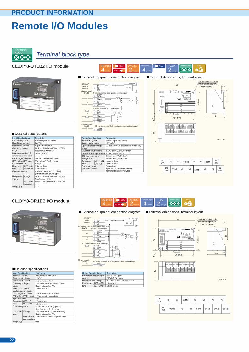
CL1XY8-DT1B2 I/O module
CL1XY8-DR1B2 I/O module
External dimensions, terminal layout External equipment connection diagram
External dimensions, terminal layout External equipment connection diagram
22 23
Output SpecificationsInsulation systemRated load voltageOperating load voltagerangeMaximum load currentOFF-time leakage currentON-time maximumvoltage dropResponsetimeSurge suppressorCommon system
OFF ON
ON OFF
DescriptionPhotocoupler insulation12/24VDC10.2 to 28.8VDC (ripple ratio within 5%)
0.1A/1 point 0.4A/1 common0.1mA or less/30VDC0.3V or less (TYP) 0.1A,0.6V or less (MAX) 0.1A1.0ms or less1.0ms or lessZener diode4 points/1 common (2 points)(terminal block 2-wire type)
Input SpecificationsInsulation systemRated input voltageRated input currentOperating voltagerangeMaximum number ofsimultaneous input pointsON voltage/ON currentOFF voltage/OFF currentInput resistanceResponse timeCommon system
Unit powersupply
Weight (kg)
OFF ONON OFF
Voltage
Max.currentconsumption
DescriptionPhotocoupler insulation24VDCApproximately 4mA20.4 to 28.8VDC (-15% to +20%)Ripple ratio within 5%100% (24VDC)
19V or more/3mA or more11V or less/1.7mA or less5.6k1.5ms or less1.5ms or less4 points/1 common (2 points)(terminal block 2-wire type)20.4 to 28.8VDC (-15% to +20%)Ripple ratio within 5%65mA or less (when all points ON)
0.10
Unit: mm
Output SpecificationsRated switching voltage,currentMaximum load voltageResponsetime
OFF ON
ON OFF
Description30VDC 2A/1 point, 250VAC 2A/1 point250VAC or less, 30VDC or less1.0ms or less1.0ms or less
Unit: mm
Input SpecificationsInsulation systemRated input voltageRated input currentOperating voltagerangeMaximum number ofsimultaneous input pointsON voltage/ON currentOFF voltage/OFF currentInput resistanceResponsetimeCommon system
Unit powersupply
Weight (kg)
OFF ONON OFF
Voltage
Max.currentconsumption
DescriptionPhotocoupler insulation24VDCApproximately 4mA20.4 to 28.8VDC(-15% to +20%)Ripple ratio within 5%100%(24VDC)
19V or more/3mA or more11V or less/1.7mA or less5.6k1.5ms or less1.5ms or less4 points/1 common (2 points)(terminal block 2-wire type)20.4 to 28.8VDC (-15% to +20%)Ripple ratio within 5%70mA or less (when all points ON)
0.11
Detailed specifications
DC24A
DC24B
DC24V
DC24G
X0 X1
COMB
COMB
X2 X3
COM +
Y3
Y0 Y1
COM + Y2
DC24A
DC24B
X0
COMB
X1
X2 X3
COMB Y0
COM2
Y1
COM2
Y2
COM2 COM1
Y3
Detailed specifications
Remote I/O ModulesPRODUCT INFORMATION
0 1 2 3
LINK/PW
CL1XY8-DT1B2
0 1 2 3
80
71.5 0.6
41
0.4IN
O U T
Y1
Y0
Y2
Y3
X1
X0
X2
X3
0 1 2 3
LINK/PW
CL1XY8-DR1B2
0 1 2 3
ON
INO U T
40 20 10 8 4 2 1ST.NO. HLD
Y1
Y0
Y2
Y3
X1
X0
X2
X3
DC24ADC24BX0COMB
1234
X1X2COMBX3
Y3
5678
DC DC
I/O power supply24VDC
+24VDADB24G
1234
Y0COM+
910
Y1Y2COM+
DC24VDC24G
111213141516
DC24ADC24B
12
Insulation
DC24ADC24BX0X1
1234
COMBX2X3COMB
5678
DC24ADC24B
12
RR
I/O interface terminal block (negative common input/sink output)
+24VDADB24G
1234
Y0COM2Y1COM2
9101112
Y2COM2Y3COM1
13141516
I/O interface terminal block (sink output)
DC DC
I/O interface terminal block(positive common input)
DIN rail center
494.
540
40
10
80
494.
540
40
10
2222
71.5 0.6
41
0.2
PW L RUN L ERR.
ON
402010 8 4 2 1HLD
STATION NO.R
R
L
L
L
RA
Memo
CC-Link/LTinterfaceconnector
I/O interface terminal block (positive common input)
I/O interface terminal block (sink output)
I/O interface terminal block (negative common input/sink output)I/O power supply
24VDC
2- 4.5 mounting hole(M4 mounting screw)
CC-Link/LTinterfaceconnector
I/O power supply24VDC
I/O power supply24VDC
Insulation
DIN rail center
2- 4.5 mounting hole(M4 mounting screw)
Terminalblock
+COM
-COM -wire type224VDC Transistor output
points4Sink
-wire type20.1A HoldTerminal blockDC input
points4
+COM
-COM -wire type224VDC Transistor output
points4 -wire type22A HoldTerminal blockDC input
points4
PW L RUN L ERR.
Remote I/O Modules
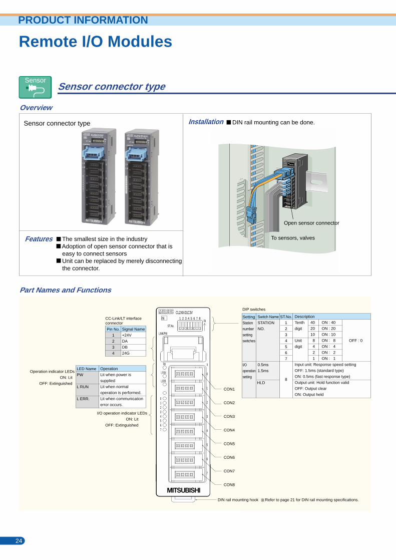
Sensor connector type
CL2X8-D1C3V input module
CL2Y8-TP1C2V output module
Sensor connector type
Overview
Part Names and Functions
Features
Installation External dimensions, terminal layoutExternal equipment connection diagram
External dimensions, terminal layoutExternal equipment connection diagram
24 25
Remote I/O ModulesPRODUCT INFORMATION
Unit: mm
Unit: mm
or+COM
Input Specifications
Insulation system
Rated input voltage
Rated input current
Operating voltage range
Maximum number of
simultaneous input points
ON voltage/ON current
OFF voltage/OFF current
Input resistance
Response
time
Common system
Unit
power
supply
Weight (kg)
OFF ON
ON OFF
Voltage
Max.current
consumption
Description
Photocoupler insulation
24VDC
Approximately 4mA
As in unit power supply
100%(24VDC)
19V or more/3mA or more
11V or less/1.7mA or less
5.6k
0.5ms/1.5ms or less (at 24VDC)
[Selected using DIP switch,
default value = OFF/1.5ms]
0.5ms/1.5ms or less (at 24VDC)
[Selected using DIP switch,
default value = OFF/1.5ms]
8 points/1 common
(sensor connector 3-wire type)
20.4 to 28.8VDC (-15% to +20%)
Ripple ratio within 5%
40mA or less (when all points ON)
0.05
Detailed specifications
InsulationInsulation
DC input
points8 -wire type224VDC
-wire type324VDC Sensor Input response
switchingVertical
Operation indicator LEDs
ON: Lit
OFF: Extinguished
I/O operation indicator LEDs
ON: Lit
OFF: Extinguished
DIN rail mounting hook Refer to page 21 for DIN rail mounting specifications.
CC-Link/LT interfaceconnector
LED Name
PW
L RUN
L ERR.
Operation
Lit when power is
supplied
Lit when normal
operation is performed.
Lit when communication
error occurs.
Pin No.
1
2
3
4
Signal Name
+24V
DA
DB
24G
DIP switches
Setting
Station
number
setting
switches
I/O
operation
setting
Switch Name
STATION
NO.
0.5ms
1.5ms
ST.No.
1
2
3
4
5
6
7
8
Description
Tenth
digit
Unit
digit
Input unit: Response speed setting
OFF: 1.5ms (standard type)
ON: 0.5ms (fast response type)
Output unit: Hold function valid
OFF: Output clear
ON: Output held
40
20
10
8
4
2
1
ON : 40
ON : 20
ON : 10
ON : 8
ON : 4
ON : 2
ON : 1
HLD
OFF : 0
Input Specifications
Insulation system
Rated load voltage
Operating load voltage
range
Maximum load current
Maximum inrush current
OFF-time leakage current
ON-time maximum
voltage drop
Response
time
Surge suppressor
Common system
Output section external
supply power
Unit
power
supply
Weight (kg)
OFF ON
ON OFF
Voltage
Max.current
consumption
Description
Photocoupler insulation
24VDC
As in unit power supply
0.1A/1 point 0.8A/common
0.7A 10ms or less
0.1mA or less
0.3V or less (TYP) 0.1A,
0.6V or less (MAX) 0.1A
0.5ms or less
0.5ms or less (resistive load)
Zener diode
8 points/1 common
(sensor connector 2-wire type)
As in unit power supply
20.4 to 28.8VDC (ripple ratio within 5%)
55mA or less (when all points ON),
external load current not included
0.05
Detailed specifications
I/O interface sensor connectorTerminal No.CON1-1CON1-2CON1-3CON1-4CON2-1CON2-2CON2-3CON2-4CON3-1CON3-2CON3-3CON3-4CON4-1CON4-2CON4-3CON4-4
Signal Name+24V+V24GX0+24V+V24GX1+24V+V24GX2+24V+V24GX3
Terminal No.CON5-1CON5-2CON5-3CON5-4CON6-1CON6-2CON6-3CON6-4CON7-1CON7-2CON7-3CON7-4CON8-1CON8-2CON8-3CON8-4
Signal Name+24V+V24GX4+24V+V24GX5+24V+V24GX6+24V+V24GX7
1234 X0
+V+24V
24G R
R
DC DC
Insulation
1234
CON2
X1
+V+24V
24GR
R
1234
CON8
X7
+V+24V
24GR
R
CON
Terminal No.CON1-1CON1-2CON1-3CON1-4CON2-1CON2-2CON2-3CON2-4CON3-1CON3-2CON3-3CON3-4CON4-1CON4-2CON4-3CON4-4
Signal Name+24VNCNCY0+24VNCNCY1+24VNCNCY2+24VNCNCY3
Terminal NoCON5-1CON5-2CON5-3CON5-4CON6-1CON6-2CON6-3CON6-4CON7-1CON7-2CON7-3CON7-4CON8-1CON8-2CON8-3CON8-4
Signal Name+24VNCNCY4+24VNCNCY5+24VNCNCY6+24VNCNCY7
L
1234
+24VDA
24GDB
1234
CON1
Y0
NC+24V
NC
1234
CON2
Y1
NC+24V
NC
1234
CON8
Y7
NC+24V
NC
L
L
DC DC
CON1
CON2
CON3
CON4
CON5
CON6
CON7
CON8
IN
ST.No.ON
LINK/PW
CL2X8-D1C3V
X
0
1
2
3
4
5
6
7
PW
L RUN
L ERR.
76543210
248
4
4
8
39
854
43
DIN rail center
IN
ST.No.ON
1 2 3 4 5 6 7 8
LINK/PW
CL2X8-D1C3V
X
0
1
2
3
4
5
6
7
PW
L RUN
L ERR.
76543210
L ERR.
L RUN
PW
7
6
5
4
3
2
1
0
Y
CL2Y8-TP1C2V
LINK/PW
ONST.No.
Open sensor connector
DIN rail mounting can be done.
The smallest size in the industry Adoption of open sensor connector that is easy to connect sensors Unit can be replaced by merely disconnecting the connector.
24
39
854
43
DIN rail center
To sensors, valves
1234
+24VDA
24GDB
CC-Link/LTinterface connector
3-wire type sensor(sink output)(NPN output type)
Detec-tioncircuit
I/O interface sensorconnector
Detectioncircuit
2-wire type sensor(sink output)
CC-Link/LTinterface connector
I/O interface sensor connectorConstant-voltagecircuit
Insulation
I/O interface sensor connector
Transistor output
points8Sink
-wire type20.1A Sensor Protection Hold Vertical
Sensor
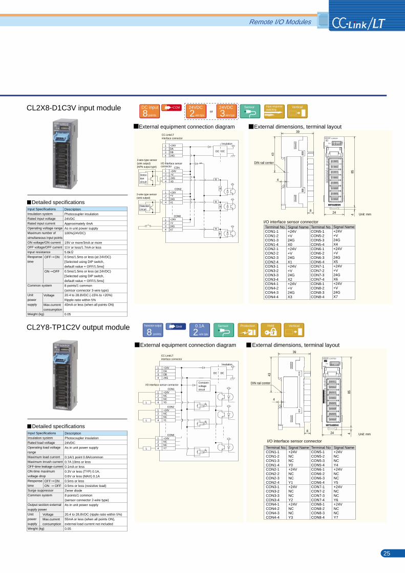
Remote I/O Modules
Sensor connector type
CL2X8-D1C3V input module
CL2Y8-TP1C2V output module
Sensor connector type
Overview
Part Names and Functions
Features
Installation External dimensions, terminal layoutExternal equipment connection diagram
External dimensions, terminal layoutExternal equipment connection diagram
24 25
Remote I/O ModulesPRODUCT INFORMATION
Unit: mm
Unit: mm
or+COM
Input Specifications
Insulation system
Rated input voltage
Rated input current
Operating voltage range
Maximum number of
simultaneous input points
ON voltage/ON current
OFF voltage/OFF current
Input resistance
Response
time
Common system
Unit
power
supply
Weight (kg)
OFF ON
ON OFF
Voltage
Max.current
consumption
Description
Photocoupler insulation
24VDC
Approximately 4mA
As in unit power supply
100%(24VDC)
19V or more/3mA or more
11V or less/1.7mA or less
5.6k
0.5ms/1.5ms or less (at 24VDC)
[Selected using DIP switch,
default value = OFF/1.5ms]
0.5ms/1.5ms or less (at 24VDC)
[Selected using DIP switch,
default value = OFF/1.5ms]
8 points/1 common
(sensor connector 3-wire type)
20.4 to 28.8VDC (-15% to +20%)
Ripple ratio within 5%
40mA or less (when all points ON)
0.05
Detailed specifications
InsulationInsulation
DC input
points8 -wire type224VDC
-wire type324VDC Sensor Input response
switchingVertical
Operation indicator LEDs
ON: Lit
OFF: Extinguished
I/O operation indicator LEDs
ON: Lit
OFF: Extinguished
DIN rail mounting hook Refer to page 21 for DIN rail mounting specifications.
CC-Link/LT interfaceconnector
LED Name
PW
L RUN
L ERR.
Operation
Lit when power is
supplied
Lit when normal
operation is performed.
Lit when communication
error occurs.
Pin No.
1
2
3
4
Signal Name
+24V
DA
DB
24G
DIP switches
Setting
Station
number
setting
switches
I/O
operation
setting
Switch Name
STATION
NO.
0.5ms
1.5ms
ST.No.
1
2
3
4
5
6
7
8
Description
Tenth
digit
Unit
digit
Input unit: Response speed setting
OFF: 1.5ms (standard type)
ON: 0.5ms (fast response type)
Output unit: Hold function valid
OFF: Output clear
ON: Output held
40
20
10
8
4
2
1
ON : 40
ON : 20
ON : 10
ON : 8
ON : 4
ON : 2
ON : 1
HLD
OFF : 0
Input Specifications
Insulation system
Rated load voltage
Operating load voltage
range
Maximum load current
Maximum inrush current
OFF-time leakage current
ON-time maximum
voltage drop
Response
time
Surge suppressor
Common system
Output section external
supply power
Unit
power
supply
Weight (kg)
OFF ON
ON OFF
Voltage
Max.current
consumption
Description
Photocoupler insulation
24VDC
As in unit power supply
0.1A/1 point 0.8A/common
0.7A 10ms or less
0.1mA or less
0.3V or less (TYP) 0.1A,
0.6V or less (MAX) 0.1A
0.5ms or less
0.5ms or less (resistive load)
Zener diode
8 points/1 common
(sensor connector 2-wire type)
As in unit power supply
20.4 to 28.8VDC (ripple ratio within 5%)
55mA or less (when all points ON),
external load current not included
0.05
Detailed specifications
I/O interface sensor connectorTerminal No.CON1-1CON1-2CON1-3CON1-4CON2-1CON2-2CON2-3CON2-4CON3-1CON3-2CON3-3CON3-4CON4-1CON4-2CON4-3CON4-4
Signal Name+24V+V24GX0+24V+V24GX1+24V+V24GX2+24V+V24GX3
Terminal No.CON5-1CON5-2CON5-3CON5-4CON6-1CON6-2CON6-3CON6-4CON7-1CON7-2CON7-3CON7-4CON8-1CON8-2CON8-3CON8-4
Signal Name+24V+V24GX4+24V+V24GX5+24V+V24GX6+24V+V24GX7
1234 X0
+V+24V
24G R
R
DC DC
Insulation
1234
CON2
X1
+V+24V
24GR
R
1234
CON8
X7
+V+24V
24GR
R
CON
Terminal No.CON1-1CON1-2CON1-3CON1-4CON2-1CON2-2CON2-3CON2-4CON3-1CON3-2CON3-3CON3-4CON4-1CON4-2CON4-3CON4-4
Signal Name+24VNCNCY0+24VNCNCY1+24VNCNCY2+24VNCNCY3
Terminal NoCON5-1CON5-2CON5-3CON5-4CON6-1CON6-2CON6-3CON6-4CON7-1CON7-2CON7-3CON7-4CON8-1CON8-2CON8-3CON8-4
Signal Name+24VNCNCY4+24VNCNCY5+24VNCNCY6+24VNCNCY7
L
1234
+24VDA
24GDB
1234
CON1
Y0
NC+24V
NC
1234
CON2
Y1
NC+24V
NC
1234
CON8
Y7
NC+24V
NC
L
L
DC DC
CON1
CON2
CON3
CON4
CON5
CON6
CON7
CON8
IN
ST.No.ON
LINK/PW
CL2X8-D1C3V
X
0
1
2
3
4
5
6
7
PW
L RUN
L ERR.
76543210
248
4
4
8
39
854
43
DIN rail center
IN
ST.No.ON
1 2 3 4 5 6 7 8
LINK/PW
CL2X8-D1C3V
X
0
1
2
3
4
5
6
7
PW
L RUN
L ERR.
76543210
L ERR.
L RUN
PW
7
6
5
4
3
2
1
0
Y
CL2Y8-TP1C2V
LINK/PW
ONST.No.
Open sensor connector
DIN rail mounting can be done.
The smallest size in the industry Adoption of open sensor connector that is easy to connect sensors Unit can be replaced by merely disconnecting the connector.
24
3985
4
43
DIN rail center
To sensors, valves
1234
+24VDA
24GDB
CC-Link/LTinterface connector
3-wire type sensor(sink output)(NPN output type)
Detec-tioncircuit
I/O interface sensorconnector
Detectioncircuit
2-wire type sensor(sink output)
CC-Link/LTinterface connector
I/O interface sensor connectorConstant-voltagecircuit
Insulation
I/O interface sensor connector
Transistor output
points8Sink
-wire type20.1A Sensor Protection Hold Vertical
Sensor
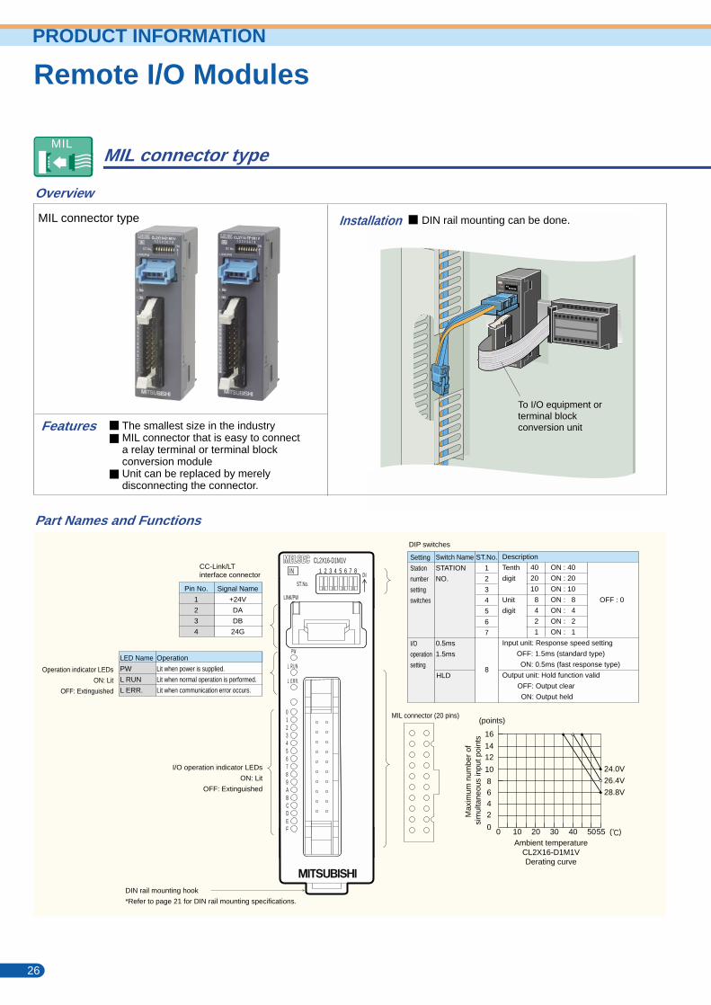
To I/O equipment orterminal blockconversion unit
External dimensions, terminal layoutExternal equipment connection diagram
External dimensions, terminal layoutExternal equipment connection diagram
MIL connector type
CL2X16-D1M1V input module
CL2Y16-TP1M1V output module
MIL connector type DIN rail mounting can be done.
Overview
Part Names and Functions
Installation
26 27
OFF ON
ON OFF
Output SpecificationsInsulation systemRated load voltageOperating load voltage rangeMaximum load currentMaximum inrush currentOFF-time leakage currentON-time maximumvoltage dropResponsetimeSurge suppressorCommon system
Output sectionexternal supplypowerUnit powersupply
Weight (kg)
VoltageCurrentconsumptionVoltageMax. currentconsumption
DescriptionPhotocoupler insulation12/24VDC10.2 to 28.8VDC(ripple ratio within 5%)0.1A/1 point 1.6A/common0.7A 10ms or less0.1mA or less0.3V or less (TYP) 0.1A,0.6V or less (MAX) 0.1A1.0ms or less1.0ms or less (resistive load)Zener diode16 points/1 common (2 points)(MIL connector 1-wire type)10.2 to 28.8VDC (ripple ratio within 5%)15mA or less (TYP. 24VDC, when all points ON)External load current not included20.4 to 28.8VDC (ripple ratio within 5%)50mA or less (when all points ON)
0.05
OFF ON
ON OFF
Input SpecificationsInsulation systemRated input voltageRated input currentOperating voltagerangeMaximum number ofsimultaneous input pointsON voltage/ON currentOFF voltage/OFF currentInput resistanceResponsetime
Common system
Unit powersupply
Weight (kg)
Voltage
Max. current consumption
DescriptionPhotocoupler insulation24VDCApproximately 4mA20.4 to 28.8VDC(-15% to +20%)Ripple ratio within 5%62.5%(24VDC)( 1)
19V or more/3mA or more11V or less/1.7mA or less5.6k0.5ms/1.5ms or less (at 24VDC)[Selected using DIP switch, default value = OFF/1.5ms]0.5ms/1.5ms or less (at 24VDC)[Selected using DIP switch, default value = OFF/1.5ms]16 points/1 common (2 points) (MIL connector 1-wire type)20.4 to 28.8VDC(-15% to +20%)Ripple ratio within 5%45mA or less (when all points ON)
0.05
* For COM+, use either of 1P and 2P or 3P and 4P.
Remote I/O ModulesRemote I/O ModulesPRODUCT INFORMATION
Unit: mm
Unit: mm
* 1) Refer to the derating curve on page 26.
Transistor output
points16Sink
-wire type10.1A MIL Protection Hold Vertical
When one powersupply is used asoutput sectionexternal supplypower and loadpower supply.
MIL
Detailed specifications
Detailed specifications
Operation indicator LEDs
ON: Lit
OFF: Extinguished
I/O operation indicator LEDs
ON: Lit
OFF: Extinguished
MIL connector (20 pins)
CC-Link/LTinterface connector
LED Name
PW
L RUN
L ERR.
Operation
Lit when power is supplied.
Lit when normal operation is performed.
Lit when communication error occurs.
Pin No.
1
2
3
4
Signal Name
+24V
DA
DB
24G
+COM
-wire type224VDC MIL Input response
switchingVertical
I/O interface MIL connectorTerminal No.CON1-1CON1-2CON1-3CON1-4CON1-20CON1-18CON1-16CON1-14CON1-12CON1-10
Signal NameCOM+COM+COM+COM+X0X1X2X3X4X5
CC-Link/LTinterface connector
1234
+24VDA
24GDB
1234
CON1COM+COM+COM+COM+
I/O interface MIL connector
R
R
R
R
5
6
7
8
9
10
11
12
13
14
15
16
17
18
19
20 X0
24VDC
XF
X7
XE
X6
XD
X5
XC
X4
XB
X3
XA
X2
X9
X1
X8
I/O power supply
DC DC
Insulation
Terminal No.CON1-1CON1-2CON1-3CON1-4CON1-20CON1-18CON1-16CON1-14CON1-12CON1-10
Signal NameCTL+CTL+COM-COM-Y0Y1Y2Y3Y4Y5
L
CC-Link/LT interface connector
1234
+24VDA
24GDB
1234
CON1CTL+CTL+COM-COM-
I/O interface MIL connector
5
6
7
8
9
10
11
12
13
14
15
16
17
18
19
20 Y0
L YF
Y7
YE
Y6
YD
Y5
YC
Y4
YB
Y3
YA
Y2
Y9
Y1
Y8
Output section external supply power
Load powersupply
L
CTL+COM-COM-
CTL+
YF
DC DC
Insulation
Terminal No.CON1-8CON1-6CON1-19CON1-17CON1-15CON1-13CON1-11CON1-9CON1-7CON1-5
Signal NameX6X7X8X9XAXBXCXDXEXF
I/O interface MIL connectorTerminal No.CON1-8CON1-6CON1-19CON1-17CON1-15CON1-13CON1-11CON1-9CON1-7CON1-5
Signal NameY6Y7Y8Y9YAYBYCYDYEYF
IN
76543210
89ABCDEF
85424
39
53
L E R R .
L R U N
P W
CL2X16-D1M1V
LINK/PW
ONST.No.
43
DIN rail center
IN
76543210
89ABCDEF
L E R R .
L R U N
P W
CL2X16-D1M1V
LINK/PW
ONST.No.
OUT
ST.No.ON
LINK/PW
CL2Y16-TP1M1V
PW
L RUN
L ERR.
85424
39
53
43
DIN rail center
Features The smallest size in the industryMIL connector that is easy to connecta relay terminal or terminal blockconversion moduleUnit can be replaced by merelydisconnecting the connector.
4
4
Setting
Station
number
setting
switches
I/O
operation
setting
Switch Name
STATION
NO.
0.5ms
1.5ms
ST.No.
1
2
3
4
5
6
7
8
Description
Tenth
digit
Unit
digit
Input unit: Response speed setting
OFF: 1.5ms (standard type)
ON: 0.5ms (fast response type)
Output unit: Hold function valid
OFF: Output clear
ON: Output held
40
20
10
8
4
2
1
ON : 40
ON : 20
ON : 10
ON : 8
ON : 4
ON : 2
ON : 1
HLD
OFF : 0
DIP switches
DIN rail mounting hook
*Refer to page 21 for DIN rail mounting specifications.
1 2 3 4 5 6 7 8
10 20 30 40 500 550
1214
16
24.0V
26.4V
28.8V
CL2X16-D1M1VDerating curve
Ambient temperature( )
68
10
24
(points)
Max
imum
num
ber
of
sim
ulta
neou
s in
put p
oint
s
DC input
points16
Constant-voltagecircuit
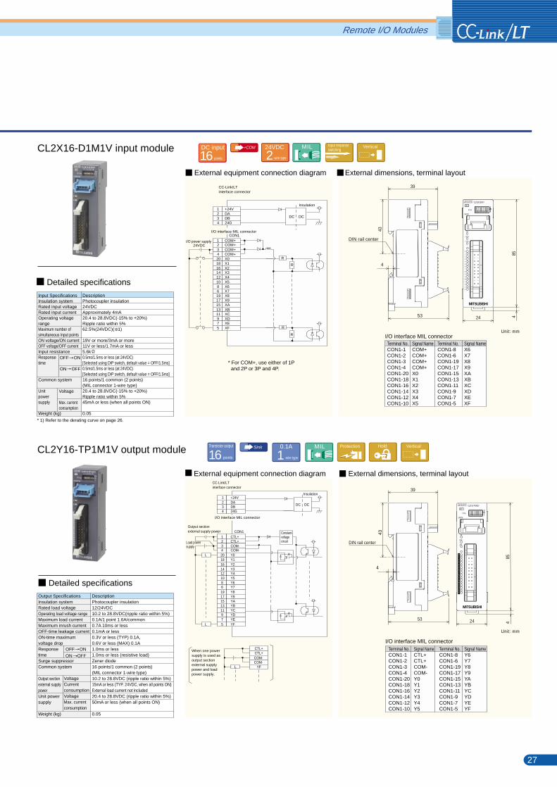
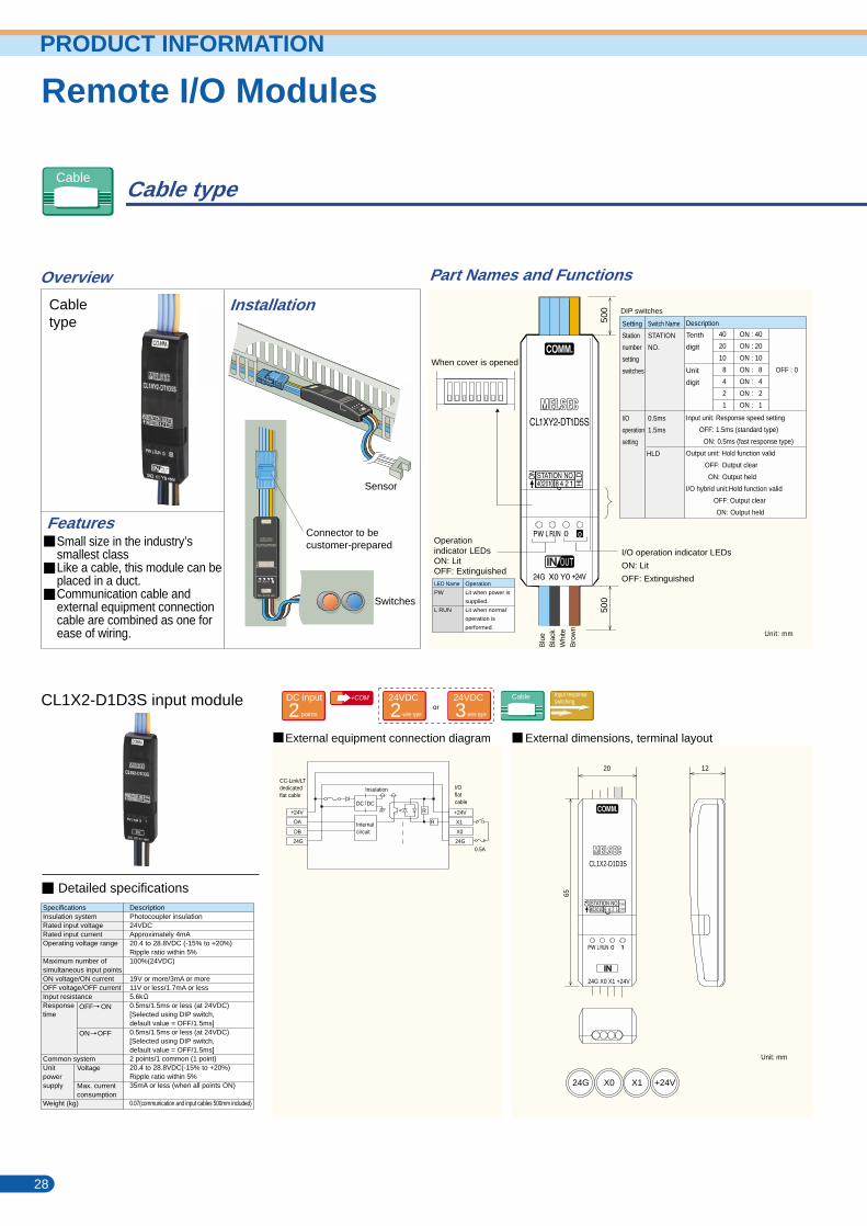
Cable type
CL1X2-D1D3S input module CL1XY2-DT1D5S I/O module
CL1Y2-T1D2S output module
Cabletype
Sensor
Overview
Installation
Part Names and Functions
External dimensions, terminal layoutExternal equipment connection diagram External dimensions, terminal layoutExternal equipment connection diagram
External dimensions, terminal layoutExternal equipment connection diagram
Unit: mm
Unit: mm Unit: mm
Unit: mm
or+COM
orDC input
points2 -wire type224VDC
-wire type324VDC Cable Input response
switching
OFF ON
ON OFF
SpecificationsInsulation systemRated input voltageRated input currentOperating voltage range
Maximum number ofsimultaneous input pointsON voltage/ON currentOFF voltage/OFF currentInput resistanceResponsetime
Common systemUnitpowersupply
Weight (kg)
Voltage
Max. currentconsumption
DescriptionPhotocoupler insulation24VDCApproximately 4mA20.4 to 28.8VDC (-15% to +20%)Ripple ratio within 5%100%(24VDC)
19V or more/3mA or more11V or less/1.7mA or less5.6k0.5ms/1.5ms or less (at 24VDC)[Selected using DIP switch,default value = OFF/1.5ms]0.5ms/1.5ms or less (at 24VDC)[Selected using DIP switch, default value = OFF/1.5ms]2 points/1 common (1 point)20.4 to 28.8VDC(-15% to +20%)Ripple ratio within 5%35mA or less (when all points ON)
0.07(communication and input cables 500mm included)
Transistor output
points2Sink
-wire type20.1A Cable Hold
OFF ONON OFF
Output SpecificationsInsulation systemRated load voltageOperating load voltage rangeMaximum load currentMaximum rush currentOFF-time leakage currentON-time maximum voltage dropResponsetimeSurge suppressorCommon systemUnit powersupply
Weight (kg)
VoltageMax. currentconsumption
DescriptionPhotocoupler insulation24VDC20.4 to 28.8VDC (ripple ratio within 5%)0.1A/1 point 0.4A/1 common0.4A/10ms0.1mA or less/30VDC1V or less (MAX) 0.1A
1.0ms or less1.0ms or less (resistive load)Zener diode2 points/1 common (1 point)20.4 to 28.8VDC (ripple ratio within 5%)35mA or less (when all points ON)
0.07(communication and input cables 500mm included)
DC input
points1+COM
-wire type224VDC
-wire type324VDC Transistor output
points1Sink
-wire type20.1A Cable Hold
Detailed specifications
Detailed specifications
I/O operation indicator LEDs
ON: Lit
OFF: Extinguished
Operationindicator LEDsON: LitOFF: ExtinguishedLED Name
PW
L RUN
Operation
Lit when power is
supplied.
Lit when normal
operation is
performed.
28 29
DIP switches
Setting
Station
number
setting
switches
I/O
operation
setting
Switch Name
STATION
NO.
0.5ms
1.5ms
Description
Tenth
digit
Unit
digit
Input unit: Response speed setting
OFF: 1.5ms (standard type)
ON: 0.5ms (fast response type)
Output unit: Hold function valid
OFF: Output clear
ON: Output held
I/O hybrid unit:Hold function valid
OFF: Output clear
ON: Output held
40
20
10
8
4
2
1
ON : 40
ON : 20
ON : 10
ON : 8
ON : 4
ON : 2
ON : 1
HLD
OFF : 0
Input SpecificationsInsulation systemRated input voltageRated input currentOperating voltagerangeMaximum number ofsimultaneous input pointsON voltage/ON currentOFF voltage/OFF currentInput resistanceUnit powersupply
Weight (kg)
Voltage
Max.currentconsumption
DescriptionPhotocoupler insulation24VDCApproximately 4mA20.4 to 28.8VDC (-15% to +20%)Ripple ratio within 5%100% (24VDC)
19V or more/3mA or more11V or less/1.7mA or less5.6k20.4 to 28.8VDC (-15% to +20%)Ripple ratio within 5%35mA or less (when all points ON)
0.07 (communication and input cables 500mm included)
Detailed specificationsOutput SpecificationsInsulation systemRated load voltageOperating load voltagerangeMaximum load currentMaximum rush currentOFF-time leakage currentON-time maximumvoltage dropResponsetimeSurge suppressorCommon system
OFF ON
ON OFF
DescriptionPhotocoupler insulation24VDC20.4 to 28.8VDC (ripple ratio within 5%)
0.1A/1 point 0.4A/common0.4A/10ms0.1mA or less/30VDC1V or less (MAX) 0.1A
1.0ms or less1.0ms or less (resistive load)Zener diode1 point/1 common (1 point)
24G
DA
DB
+24V
DC DC
Insulation
CC-Link/LTdedicated flat cable
R
X1
X0
0.5A
0.5A
0.5A
0.5A
+24V
24G
R
I/Oflatcable
Internalcircuit
24G X0 X1 +24V 24G X0 Y0 +24V
24G Y0 Y1 +24V
20
65
12
20
65
12
500
500
24G X0 X1 +24V
24G Y0 Y1 +24V
When cover is opened
Connector to becustomer-prepared
Switches
20
65
12
Remote I/O ModulesRemote I/O ModulesPRODUCT INFORMATION
FeaturesSmall size in the industry’ssmallest classLike a cable, this module can beplaced in a duct.Communication cable andexternal equipment connectioncable are combined as one forease of wiring.
CL1X2-D1D3S
CL1Y2-T1D2S
CL1XY2-DT1D5S
402010 8 4 2 10.5ms1.5ms
402010 8 4 2 1
402010 8 4 2 1
0
24G
DA
DB
+24V
DC DC
Insulation
CC-Link/LTdedicatedflat cable
Y1 L
LY0
+24V
24G
I/Oflatcable
Internalcircuit
R
24G
DA
DB
+24V
DC DC
InsulationCC-Link/LTdedicatedflat cable
Y0 L
X0
+24V
24G
I/Oflatcable
Internalcircuit
R
R
R
24G X0 Y0 +24V
Cable
Blu
eB
lack
Whi
teB
row
n
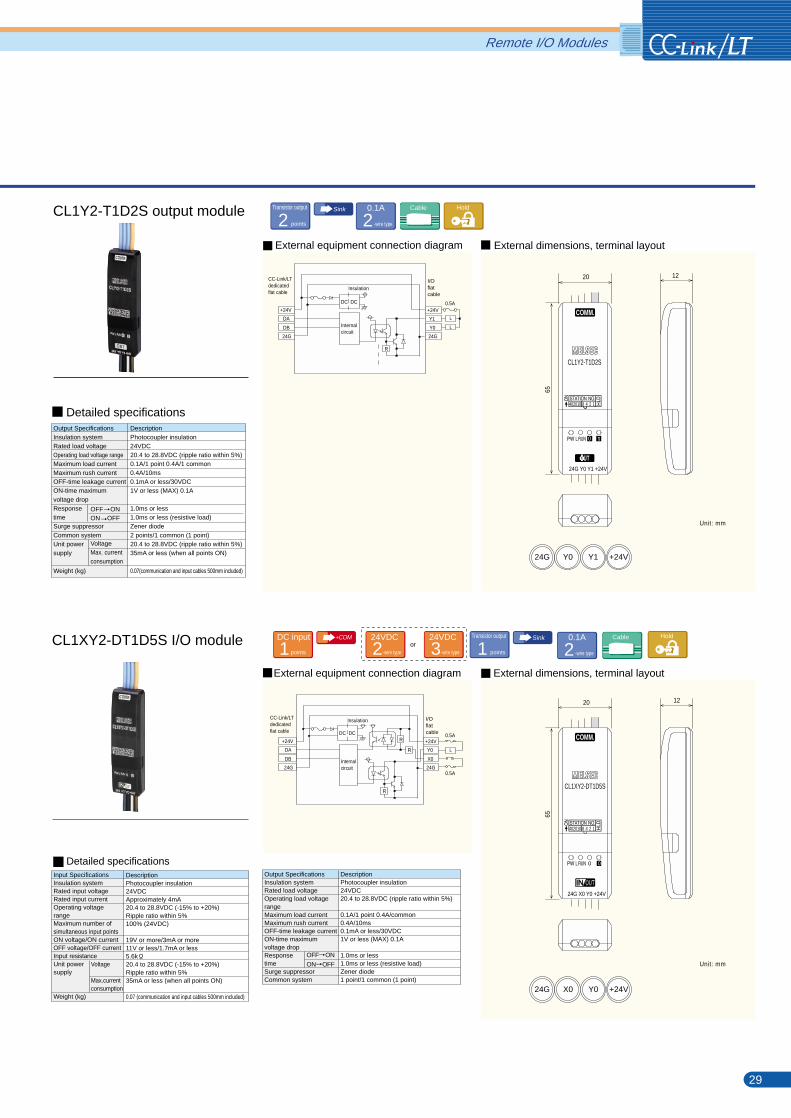
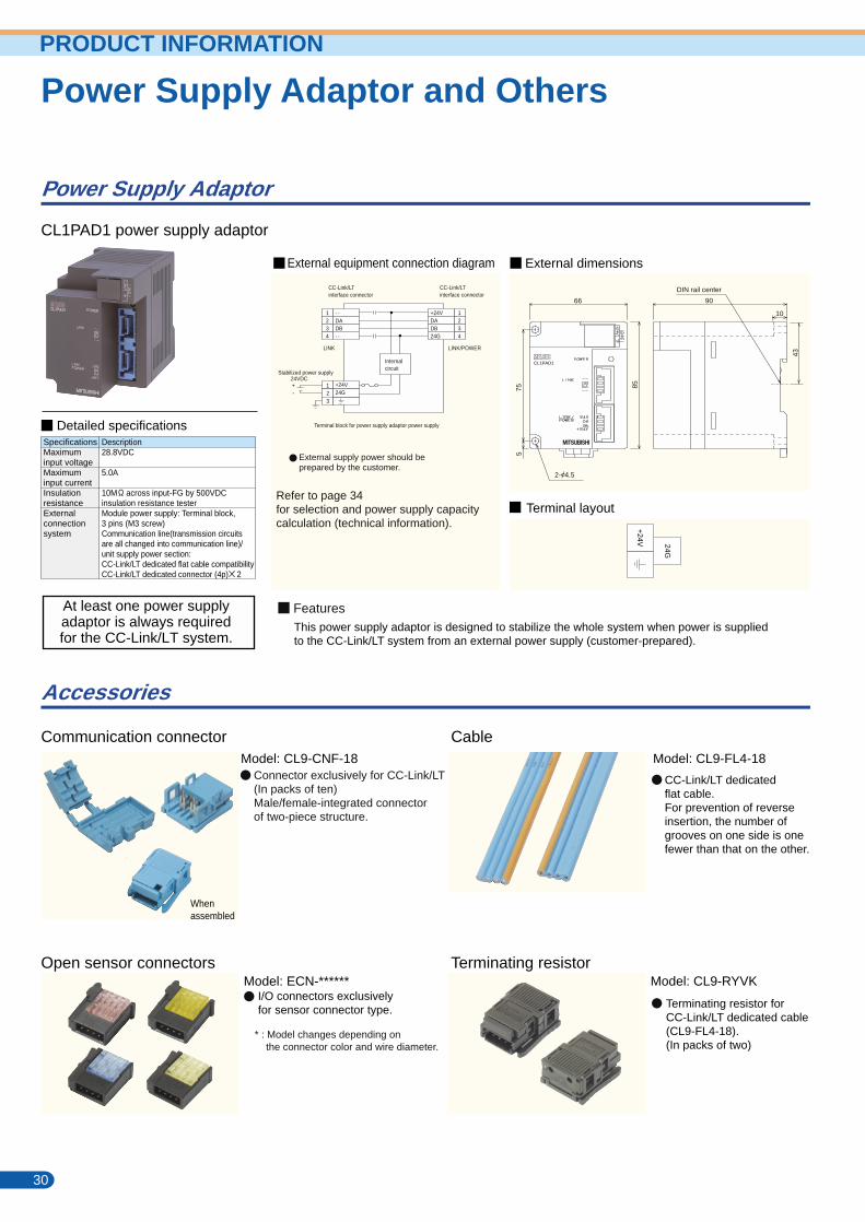
Power Supply Adaptor
Accessories
Software (MELSEC Programming Software)
CL1PAD1 power supply adaptor GX-Developer SW D5C-GPPW-E
Communication connectorModel: CL9-CNF-18 Model: CL9-FL4-18
Model: ECN-****** Model: CL9-RYVKOpen sensor connectors
Cable
Terminating resistor
CC-Link/LT can be diagnosed/monitored using GX Developer.
Operating environment
OS
CPU
Display
Memory
Hard disk capacity
Disk drive
Windows 95 (English version), Windows 98 (English version)
Windows NT Workstation 4.0 (English version),
Windows 2000 (English version), Windows ME (English version)
Pentium 133MHz or more
Resolution 800 600 dots or more (recommended 1024 768 dots)
32MB or more
80MB or more
3.5 inch (1.44MB) floppy disk drive, CD-ROM drive
Product
GX Developer
Environment
SW D5C-GPPW-EOperating Manual (SH-080166)
Mitsubishi Integrated FA Software Catalog (L(NA)08008)
Description
MELSEC PLC software package
External dimensions
Terminal layout
External equipment connection diagram
* : Model changes depending on the connector color and wire diameter.
Whenassembled
EnvironmentItem
Relevant Manuals, Etc.
Detailed specificationsSpecificationsMaximuminput voltageMaximuminput currentInsulationresistanceExternalconnectionsystem
Description28.8VDC
5.0A
10M across input-FG by 500VDC insulation resistance testerModule power supply: Terminal block, 3 pins (M3 screw)Communication line(transmission circuitsare all changed into communication line)/unit supply power section:CC-Link/LT dedicated flat cable compatibilityCC-Link/LT dedicated connector (4p) 2
CC-Link/LTinterface connector
1234
- -DA
- -DB
1234
123
24VDC
Internalcircuit
CC-Link/LTinterface connector
Terminal block for power supply adaptor power supply
Stabilized power supply
+24VDA
24GDB
LINK LINK/POWER
At least one power supplyadaptor is always requiredfor the CC-Link/LT system.
CLC13 (master station)Having a built-in communication protocol, this LSI allows you to develop the product that will control data communication and remote stations, without being conscious of a communication protocol, by performing memory read/write from an external CPU.
CLC21 (remote I/O station)Having a built-in communication protocol, this LSI allows you to develop the product that will handle bit data, without using an external CPU (programless).
External supply power should beprepared by the customer.
Refer to page 34for selection and power supply capacitycalculation (technical information).
FeaturesThis power supply adaptor is designed to stabilize the whole system when power is suppliedto the CC-Link/LT system from an external power supply (customer-prepared).
Open System Center, Nagoya Works,Mitsubishi Electric CorporationTel:+81-52-712-2369 Fax:+81-52-712-2419 Open: 9:00 to 12:00, 13:00 to 17:00(Except Saturdays, Sundays, nationalholidays and our holidays)
30 31
Soon to be released
24G
+24V
+-
Connector exclusively for CC-Link/LT(In packs of ten)Male/female-integrated connectorof two-piece structure.
I/O connectors exclusivelyfor sensor connector type.
CC-Link/LT dedicatedflat cable.For prevention of reverseinsertion, the number ofgrooves on one side is onefewer than that on the other.
Terminating resistor forCC-Link/LT dedicated cable(CL9-FL4-18).(In packs of two)
The QCPU allows host monitor, other stationmonitor and line monitor to be performed in "CC-Link/LT diagnostics" of GX Developer.
To purchase the communication LSIs, you needto become a member (regular or higher member)of the CC-Link Partner Association (CLPA). Refer to page 36 for the CC-Link Partner Association.For details of the communication LSIs, contact the following Open System Center.
Product
Order model
Packing unit
Application
CLC13
CL2GA13-60
60 pcs.
Master station
CLC21
CL2GA21-60
60 pcs.
CL2GA21-300
300 pcs.
CLC13 (for master station), CLC21 (for remote I/O station)You can develop CC-Link/LT compatible products easilywithout being conscious of a communication protocol.
Precautions
CLC:CC-Link/LT Controller
Power Supply Adaptor and OthersPower Supply Adaptor and OthersPRODUCT INFORMATION
66 90
10
75 85
5
43
2- 4.5
CL1PAD1
DIN rail center
Remote I/O station
CC-Link/LT Dedicated Communication LSIs
24G+24V
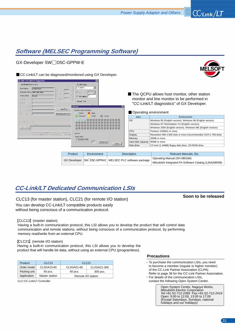
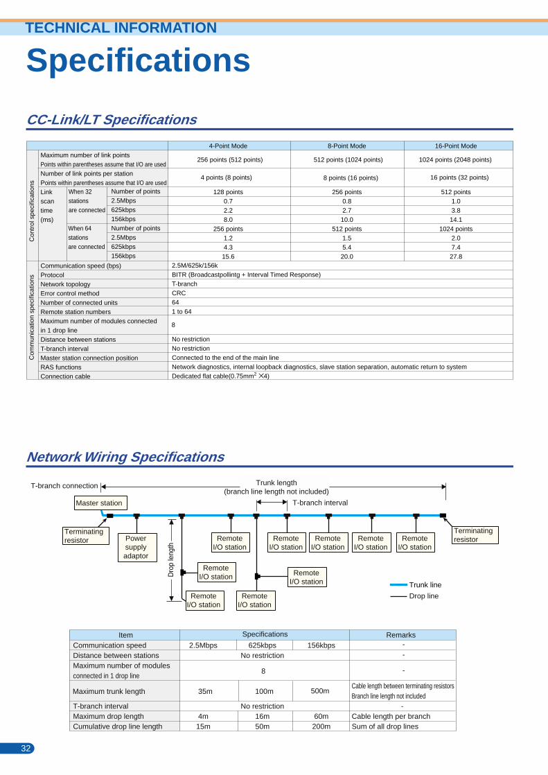
Specifications
CC-Link/LT Specifications
Network Wiring Specifications
Maximum number of link pointsPoints within parentheses assume that I/O are usedNumber of link points per stationPoints within parentheses assume that I/O are usedLinkscantime(ms)
Communication speed (bps)ProtocolNetwork topologyError control methodNumber of connected unitsRemote station numbersMaximum number of modules connectedin 1 drop lineDistance between stationsT-branch intervalMaster station connection positionRAS functionsConnection cable
Number of points2.5Mbps625kbps156kbpsNumber of points2.5Mbps625kbps156kbps
2.5M/625k/156kBITR (Broadcastpollintg + Interval Timed Response)T-branchCRC641 to 64
No restrictionNo restrictionConnected to the end of the main lineNetwork diagnostics, internal loopback diagnostics, slave station separation, automatic return to systemDedicated flat cable(0.75mm2 4)
4-Point Mode
128 points0.72.28.0
256 points1.24.3
15.6
8-Point Mode
256 points0.82.7
10.0512 points
1.55.4
20.0
16-Point Mode
512 points1.03.8
14.11024 points
2.07.4
27.8
Cable Specifications
General Specifications
ItemCable typeOperating temperature rangeRated voltageNumber of coresConductor resistance (20 )SafetyFlame resistance
SpecificationsFlat cable-10 to 8030V423.4 /Km or lessUL Subject 758UL VW-1 -F-
CC-Link/LT dedicated flat cable specifications
Section
General specifications indicate the specifications of the environment where these products can be installed and operated. Unless otherwise exceptional specifications are indicated, the general specifications apply to all products.Install and operate the products in the environment given in the general specifications.
Item Specifications
0 to 55 (*1)
-25 to 75 (*1)
Conforming to JIS B 3502, IEC61131-2, level RH-2 (5 to 95%RH, non-condensing)
Conforming to JIS B 3502, IEC61131-2, level RH-2 (5 to 95%RH, non-condensing)
Conforming to
JIS B 3502,
IEC 61131-2
Operating ambient temperature
Storage ambient temperature
Operating ambient humidity
Storage ambient humidity
Vibration resistance
Shock resistance
Operating atmosphere
Operating altitude
Installation place
Overvoltage category
Pollution level
Conforming to JIS B 3502, IEC 61131-2 (147m/s, 3 times in each of directions X, Y, Z)
No corrosive gases
Conforming to JIS B 3502, IEC 61131-2 (2000m or less) (*2)
Inside control box(*3)
Conforming to JIS B 3502, IEC 61131-2 (category II or less)(* 4)
Conforming to JIS B 3502, IEC 61131-2, pollution level 2 or less(*5)
Under intermittent vibration
Frequency
10 to 57Hz
57 to 150Hz
Under continuous vibration
Frequency
10 to 57Hz
57 to 150Hz
Sweep count
10 times each in X, Y, Z
directions (for 80 minutes)
Acceleration
-
9.8m/s
Acceleration
-
4.9m/s
Amplitude
0.075mm
Amplitude
0.035mm
-
The operating/storage ambient temperature satisfies the requirements that exceed the stipulations of JIS B 3502 and IEC61131-2.The equipment cannot be used under pressure higher than the atmospheric pressure of altitude 0m. Doing so can cause a failure.The equipment can be used in any environment other than in a control box if it satisfies the conditions such as the operating ambient temperature and operating ambient humidity.This indicates the section of the power supply to which the equipment is assumed to be connected between the public electrical power distribution network and the machinery within premises. Category II applies to equipment for which electrical power is supplied from fixed facilities. The surge voltage withstand level for up to the rated voltage of 300V is 2500V.This index indicates the degree to which conductive material is generated in the environment where the equipment is used. In pollution level 2, only non-conductive pollution occurs but temporary conductivity may be produced due to condensing.
2
2
2
*1)*2)*3)*4)
*5)
--
-
-
Con
trol
spe
cific
atio
ns
When 32stationsare connected
When 64 stationsare connected
Com
mun
icat
ion
spec
ifica
tions
256 points (512 points) 512 points (1024 points) 1024 points (2048 points)
4 points (8 points) 8 points (16 points) 16 points (32 points)
8
32 33
SpecificationsTECHNICAL INFORMATION
T-branch connection
T-branch interval
Terminatingresistor
RemoteI/O station
RemoteI/O station
RemoteI/O station Remote
I/O station
RemoteI/O station
RemoteI/O station
RemoteI/O station
RemoteI/O station
RemoteI/O station
Powersupplyadaptor
Trunk length(branch line length not included)
Master station
Dro
p le
ngth
Terminatingresistor
Trunk line
Drop line
Cable length between terminating resistorsBranch line length not included
Cable length per branchSum of all drop lines
Communication speedDistance between stationsMaximum number of modulesconnected in 1 drop line
T-branch intervalMaximum drop lengthCumulative drop line length
2.5Mbps
4m15m
156kbps
60m200m
625kbpsNo restriction
No restriction16m50m
Ground color (light blue) Polarity mark (orange)
10.16mm
2.54mm
2.54
mm
Item Specifications Remarks
Maximum trunk length 35m 100m 500m
8
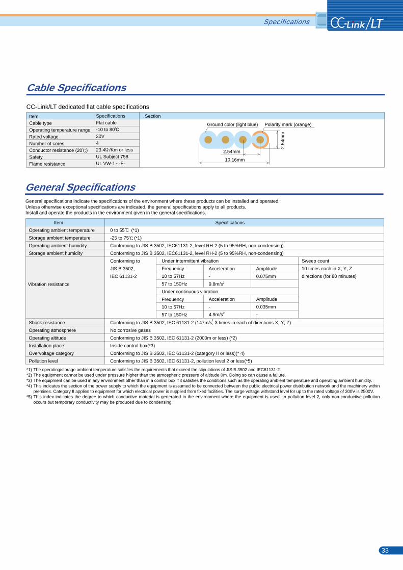
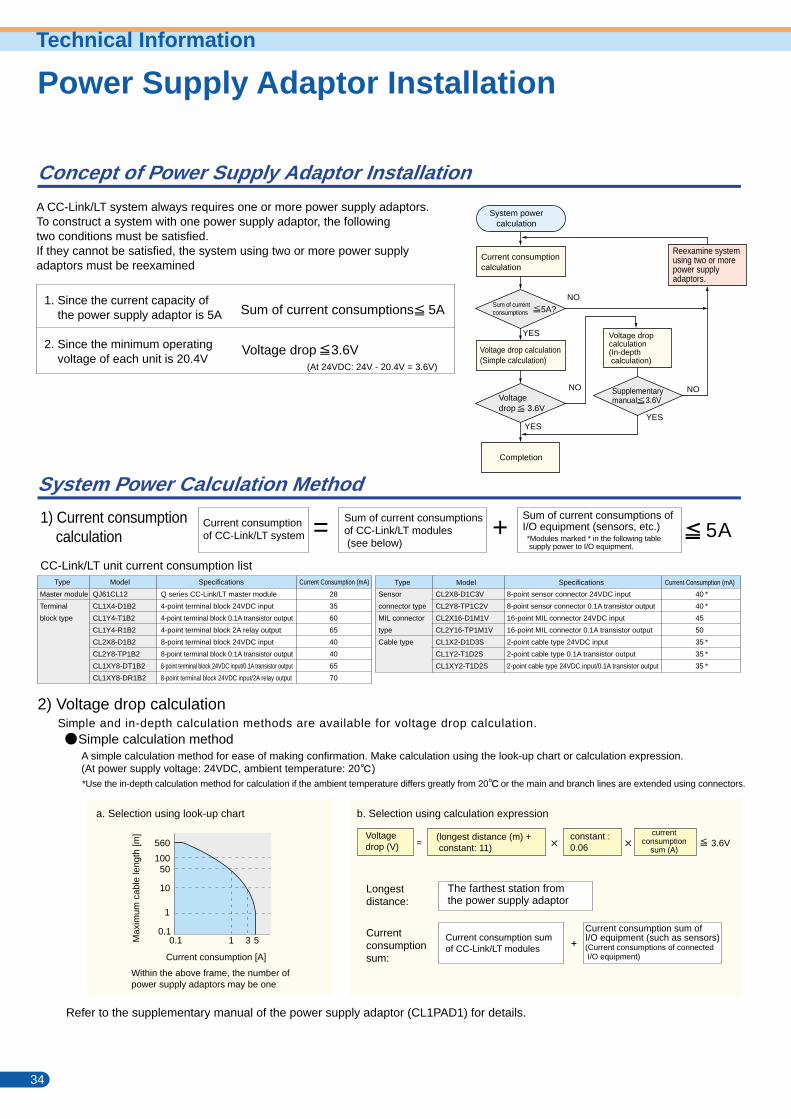
Concept of Power Supply Adaptor Installation
System Power Calculation Method
Current consumptionof CC-Link/LT system = Sum of current consumptions
of CC-Link/LT modules (see below)
+Sum of current consumptions ofI/O equipment (sensors, etc.)
CC-Link/LT unit current consumption list
1) Current consumption calculation
40
40
45
50
35
35
35
*
*
*
*
*
2) Voltage drop calculationSimple and in-depth calculation methods are available for voltage drop calculation.
Refer to the supplementary manual of the power supply adaptor (CL1PAD1) for details.
5A
Master module
Terminal
block type
28
35
60
65
40
40
65
70
Sensor
connector type
MIL connector
type
Cable type
CL2X8-D1C3V
CL2Y8-TP1C2V
CL2X16-D1M1V
CL2Y16-TP1M1V
CL1X2-D1D3S
CL1Y2-T1D2S
CL1XY2-T1D2S
8-point sensor connector 24VDC input
8-point sensor connector 0.1A transistor output
16-point MIL connector 24VDC input
16-point MIL connector 0.1A transistor output
2-point cable type 24VDC input
2-point cable type 0.1A transistor output
2-point cable type 24VDC input/0.1A transistor output
QJ61CL12
CL1X4-D1B2
CL1Y4-T1B2
CL1Y4-R1B2
CL2X8-D1B2
CL2Y8-TP1B2
CL1XY8-DT1B2
CL1XY8-DR1B2
Q series CC-Link/LT master module
4-point terminal block 24VDC input
4-point terminal block 0.1A transistor output
4-point terminal block 2A relay output
8-point terminal block 24VDC input
8-point terminal block 0.1A transistor output
8-point terminal block 24VDC input/0.1A transistor output
8-point terminal block 24VDC input/2A relay output
a. Selection using look-up chart b. Selection using calculation expression
A simple calculation method for ease of making confirmation. Make calculation using the look-up chart or calculation expression. (At power supply voltage: 24VDC, ambient temperature: 20 )*Use the in-depth calculation method for calculation if the ambient temperature differs greatly from 20 or the main and branch lines are extended using connectors.
Longestdistance:
Currentconsumptionsum:
The farthest station fromthe power supply adaptor
Current consumption sumof CC-Link/LT modules
Current consumption sum ofI/O equipment (such as sensors)(Current consumptions of connected I/O equipment)
(longest distance (m) + constant: 11)
Voltagedrop (V) =
constant : 0.06
currentconsumption
sum (A)
*Modules marked * in the following table supply power to I/O equipment.
Model SpecificationsType Current Consumption (mA) Model SpecificationsType Current Consumption (mA)
Max
imum
cab
le le
ngth
[m]
Within the above frame, the number of power supply adaptors may be one
3.6V
Simple calculation method
1. Since the current capacity of the power supply adaptor is 5A
2. Since the minimum operating voltage of each unit is 20.4V
Sum of current consumptions 5A
Voltage drop 3.6V
YES
YES
YES
NO
NO
NO
System powercalculation
Current consumptioncalculation
5A?
Voltagedrop 3.6V
Supplementarymanual 3.6V
Voltage drop calculation(Simple calculation)
Voltage dropcalculation(In-depth calculation)
Completion
Reexamine system using two or more power supply adaptors.
Calculation Examples
4m
1m
2m
5m
0.5m
5m 10m 10m
0.2m4m
0.2m
3m
4m
4m
3m
0.2m
0.2m
Trunk line
Drop line
Longest distance
1) Current consumption calculation
<System configuration example>
2) Voltage drop calculation
(35.5m+constant: 11) constant: 0.06 0.9A = 2.511V 3.6V
Sum of current consumptions
28mA + 100mA + 60mA + 80mA + 200mA + 60mA + 150mA + 250mA = 928mA = 0.9A 5A
Longest distance: The remotest station from the power supply adaptor, station 7) of branch line D
(At 24VDC: 24V - 20.4V = 3.6V)
Master station28mA
From above 1) and 2), both the current and voltage can be suppliedby one power supply adaptor.
34 35
Station 1)Masterstation
Station 2) Station 3) Station 4) Station 5) Station 6) Station 7)
Sum of current consumptions
Current consumption [A]
0.1
1
0.1 1 3 5
10
50100
560
A CC-Link/LT system always requires one or more power supply adaptors.To construct a system with one power supply adaptor, the followingtwo conditions must be satisfied.If they cannot be satisfied, the system using two or more power supplyadaptors must be reexamined
Station 1)100mA
Station 2)60mA Station 3)
80mA
Station 4)200mA
Station 5)60mA
Station 6)150mA
Station 7)250mA
Power supplyadaptor
General-purposepower supply
*The output current of the general-purpose power supply must be equal to or greater than the current consumption of the CC-Link/LT system. (Maximum 5A or less)
*The above current consumption of each station includes the current consumption of the connected I/O equipment.
Branchline A
Branchline C
Branchline B
Branchline D
Power Supply Adaptor InstallationPower Supply Adaptor InstallationTechnical Information
0.5m + 4m + 5m + 5m + 10m + 4m + 4m + 3m = 35.5m
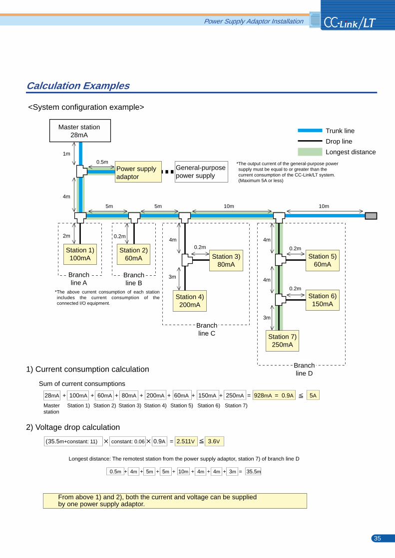
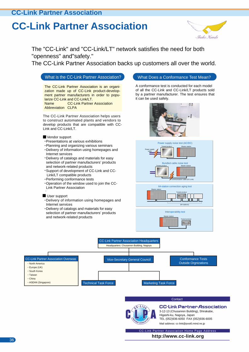
36 37
CC-Link Partner AssociationCC-Link Partner AssociationCC-Link Partner Association
A conformance test is conducted for each modelof all the CC-Link and CC-Link/LT products sold by a partner manufacturer. The test ensures that it can be used safely.
What Does a Conformance Test Mean?
Bundled cable noise testMaster stationTested product
Communication cable (CC-Link)
64-station connection aging test
(64 stations)
Master station
Tested product
Interoperability test
Master station
Tested product
Power supply noise test (AC/DC)Master stationTested product
Power supplycable
The CC-Link Partner Association is an organi-zation made up of CC-Link product-develop-ment partner manufacturers in order to popu-larize CC-Link and CC-Link/LT.Name CC-Link Partner AssociationAbbreviation CLPA
The CC-Link Partner Association helps usersto construct automated plants and vendors todevelop products that are compatible with CC-Link and CC-Link/LT.
Vendor support Presentations at various exhibitions Planning and organizing various seminars Delivery of information using homepages and Internet services Delivery of catalogs and materials for easy selection of partner manufacturers’ products and network-related products Support of development of CC-Link and CC-Link/LT compatible products
Performing conformance tests Operation of the window used to join the CC- Link Partner Association
User support Delivery of information using homepages and Internet services Delivery of catalogs and materials for easy selection of partner manufacturers’ products and network-related products
CC-Link Partner Association OverseasNorth America
Europe (UK)
South Korea
Taiwan
China
ASEAN (Singapore)
Conformance TestsOutside Orgnizations
CC-Link Partner Association HeadquartersHeadquarters: Chusanren Building, Nagoya
Vice-Secretary General Council
Marketing Task ForceTechnical Task Force
3-12-13 (Chusanren Building), Shirakabe, Higashi-ku, Nagoya, JapanTEL (052)936-6050 FAX (052)936-6005
Mail address: [email protected]
Contact
http://www.cc-link.orgCC-Link Partner Associat ion Home Page Address
The "CC-Link" and "CC-Link/LT" network satisfies the need for both "openness" and"safety."The CC-Link Partner Association backs up customers all over the world.
Memo
What is the CC-Link Partner Association?
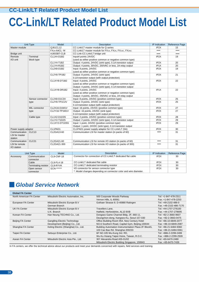
CC-Link/LT Related Product Model List
Unit TypeMaster module
Bridge unitRemoteI/O unit
Power supply adaptorCommunicationLSI for master stationCommunicationLSI for remoteI/O station
Terminalblock type
Sensor connectortype
MIL connectortype
Cable type
CLC13
CLC21
IP IndicationIP2X
IP2X
IP2XIP1XIP2X
IP2X
IP2X
IP1X
IP2XIP2X
IP2XIP2X
IP2XIP2XIP2X
IP2X
Reference Page15
19
202019
21
22
22
2525
2727
282929
3031
3131
ModelQJ61CL12FX2N-64CL- MAJ65SBT-CLBCL1X4-D1B2
CL1Y4-T1B2 CL1Y4-R1B2CL2X8-D1B2
CL2Y8-TP1B2
CL1XY8-DT1B2
CL1XY8-DR1B2
CL2X8-D1C3V CL2Y8-TP1C2V
CL2X16-D1M1V CL2Y16-TP1M1V
CL1X2-D1D3SCL1Y2-T1D2S CL1XY2-DT1D5S
CL1PAD1CL2GA13-60
CL2GA21-60CL2GA21-300
DescriptionCC-Link/LT master module for Q seriesCC-Link/LT master module for FX1N, FX2N, FX1NC, FX2NC
CC-Link-CC-Link/LT bridge unitInput4 points:24VDC(used as either positive common or negative common type)Output: 4 points, 24VDC (sink type), 0.1A transistor outputOutput: 4 points, 30VDC, 250VAC or less, 2A relay outputInput: 8 points, 24VDC(used as either positive common or negative common type)Output: 8 points, 24VDC (sink type)0.1A transistor output (with output protection)Input: 4 points, 24VDC(used as either positive common or negative common type)Output: 4 points, 24VDC (sink type), 0.1A transistor outputInput: 4 points, 24VDC(used as either positive common or negative common type)Output: 4 points, 30VDC, 250VAC or less, 2A relay outputInput: 8 points, 24VDC (positive common type)Output: 8 points, 24VDC (sink type)0.1A transistor output (with output protection)Input: 16 points, 24VDC (positive common type)Output: 16 points, 24VDC (sink type)0.1A transistor output (with output protection)Input: 2 points, 24VDC (positive common type)Output: 2 points, 24VDC (sink type), 0.1A transistor outputInput: 1 point, 24VDC (positive common type)Output: 1 point, 24VDC (sink type), 0.1A transistor outputCL1PAD1 power supply adaptor for CC-Link/LT (5A)Communication LSI for master station (in packs of 60)
Communication LSI for remote I/O station (in packs of 60)Communication LSI for remote I/O station (in packs of 300)
Unit TypeAccessory Communication
connectorCableTerminating resistorOpen sensorconnector
CL9-CNF-18
CL9-FL4-18CL9-RYVKECN-******
Model DescriptionConnector for connection of CC-Link/LT dedicated flat cable
CC-Link/LT dedicated flat cableCC-Link/LT dedicated terminating resistorI/O connector for sensor connector type*: Model changes depending on connector color and wire diameter.
IP IndicationIP2X
IP2XIP2XIP2X
Reference Page30
303030
38 39
CC-Link/LT Related Product Model ListCC-Link/LT Related Product Model List
Global Service Network
Memo
Global FA CenterNorth American FA Center
European FA Center
UK FA Center
Korean FA Center
Beijing FA Center
Shanghai FA Center
Taipei FA Center
Asean FA Center
In FA centers, we offer the technical advice about our products and meet your demands concerned with repairs, field services and training.
Mitsubishi Electric Automation, Inc.
Mitsubishi Electric Europe B.VGerman BranchMitsubishi Electric Europe B.V U.K. BranchHan Neung TECHNO Co., Ltd.
Ganglling Electric TechnologyDevelopment (Beijing) Co., Ltd.Keling Electric (Shanghai) Co., Ltd.
Setsuyo Enterprise Co., Ltd.
Mitsubishi Electric Asia Pte., Ltd.
500 Corporate Woods ParkwayVernon Hills, IL 60061Gothaer Strasse 8. D-40880 Ratingen
Travellers Lane,Hatfield, Herfordshire, AL10 8XBDongseo Game Channel Bldg. 2F, 660-11, Deungchon-dong, Kangseo-Ku, Seoul 157-030Office Building Room 954, New Century HotelNO.6 Southern Road, Capital Gym, Beijing,100044Building Automation Instrumentation Plaza 2F Block5,103 Cao Bao Rd. Shanghai 2002336F NO.105 Wu-Kung 3rd. RD,Wu-Ku Hsiang Taipei Hsine, Taiwan, R.O.C.307 Alexandra Road #05-01/02Mitsubishi Electric Building Singapore, 159943
Tel: +1-847-478-2311Fax: +1-847-478-2253Tel: +49-2102-486-0Fax: +49-2102-486-7170Tel: +44-1707-276100Fax: +44-1707-278695Tel: +82-2-3660-9607Fax: +82-2-3663-0475Tel: +86-10-6849-2077Fax: +86-10-6849-2087Tel: +86-21-6484-9360Fax: +86-21-6484-9361Tel: +886-2-2299-2499Fax: +886-2-2299-2509Tel: +65-6470-2480Fax: +65-6470-7439
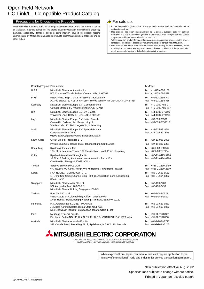
Hence its Light, This is "LT"!Handy
Easy
Open Field NetworkCC-Link/LT Compatible Product Catalog
For safe useMitsubishi will not be held liable for damage caused by factors found not to be the cause of Mitsubishi; machine damage or lost profits caused by faults in the Mitsubishi products; damage, secondary damage, accident compensation caused by special factors unpredictable by Mitsubishi; damages to products other than Mitsubishi products; and to other duties.
Precautions for Choosing the Products
L(NA)-08026E-A 0208(MEE)
When exported from Japan, this manual does not require application to theMinistry of International Trade and Industry for service transaction permission.
New publication,effective Aug. 2002
Specifications subject to change without notice.
Printed in Japan on recycled paper.
ELECTRIC CORPORATION HEAD OFFICE: 1-8-12,OFFICE TOWER Z 14F HARUMI CHUO-KU 104-6212,JAPAN
NAGOYA WORKS: 1-14,YADA-MINAMI 5,HIGASHI-KU,NAGOYA,JAPAN
Country/Region Sales office Tel/Fax
U.S.A Mitsubishi Electric Automation Inc. Tel : +1-847-478-2100500 Corporate Woods Parkway Vernon Hills, IL 60061 Fax : +1-847-478-0328
Brazil MELCO-TEC Rep. Com.e Assessoria Tecnica Ltda. Tel : +55-21-221-8343Av. Rio Branco, 123-15 ,and S/1507, Rio de Janeiro, RJ CEP 20040-005, Brazil Fax : +55-21-221-9388
Germany Mitsubishi Electric Europe B.V. German Branch Tel : +49-2102-486-0Gothaer Strasse 8 D-40880 Ratingen, GERMANY Fax : +49-2102-486-717
U.K Mitsubishi Electric Europe B.V. UK Branch Tel : +44-1707-276100Travellers Lane, Hatfield, Herts., AL10 8XB,UK Fax : +44-1707-278695
Italy Mitsubishi Electric Europe B.V. Italian Branch Tel : +39-039-60531Centro Dir. Colleoni, Pal. Perseo - Ingr.2 Fax : +39-039-6053312Via Paracelso 12, 20041 Agrate B., Milano, Italy
Spain Mitsubishi Electric Europe B.V. Spanish Branch Tel : +34-935-653135Carretera de Rubi 76-80 Fax : +34-935-89157908190 Sant Cugat del Valles, Barcelona, Spain
South Africa Circuit Breaker Industries LTD Tel : +27-11-928-2000
Private Bag 2016, Isando 1600, Johannesburg, South Africa Fax : +27-11-392-2354
Hong Kong Ryoden Automation Ltd. Tel : +852-2887-887010th Floor, Manulife Tower, 169 Electric Road, North Point, HongKong Fax : +852-2887-7984
China Ryoden International Shanghai Ltd. Tel : +86-21-6475-32283F Block5 Building Automation Instrumentation Plaza 103 Fax : +86-21-6484-6996Cao Bao Rd. Shanghai 200233 China
Taiwan Setsuyo Enterprise Co., Ltd. Tel : +886-2-2299-24996F., No.105 Wu-Kung 3rd.RD, Wu-Ku Hsiang, Taipei Hsine, Taiwan Fax : +886-2-2299-2509
Korea HAN NEUNG TECHNO CO., LTD. Tel : +82-2-3660-95521F Dong Seo Game Channel Bldg., 660-11,Deungchon-dong Kangsec-ku, Fax : +82-2-3664-8372Seoul, Korea
Singapore Mitsubishi Electric Asia Pte, Ltd. Tel : +65-473-2480307 Alexandra Road #05-01/02, Fax : +65-476-7439Mitsubishi Electric Bulding Singapore 159943
Thailand F. A. Tech Co.,Ltd. Tel : +66-2-682-6522898/28,29,30 S.V.City Building, Office Tower 2, Floor Fax : +66-2-682-602017-18 Rama 3 Road, Bangkpongpang, Yannawa, Bangkok 10120
Indonesia P.T. Autoteknindo SUMBER MAKMUR Tel : +62-21-663-0833Jl. Muara Karang Selatan Blok a Utara No.1 Kav. Fax : +62-21-663-0832No.11 Kawasan Industri/Pergudangan Jakarta-Utara 14440
India Messung Systems Put,Ltd. Tel : +91-20-7128927Electronic Sadan NO:111 Unit No15, M.I.D.C BHOSARI,PUNE-411026,India Fax : +91-20-7128108
Australia Mitsubishi Electric Australia Pty. Ltd. Tel : +61-2-9684-7777348 Victoria Road, PostalBag, No 2, Rydalmere, N.S.W 2116, Australia Fax : +61-2-9684-7245
Mitsubishi Electric Corporation Nagoya Works is a factory certified for ISO14001 (standards for environmental management systems) and ISO9001 (standards for quality assurance management systems)
http://www.nagoya.melco.co.jp/english/
To use the products given in this catalog properly, always read the "manuals" before starting to use them.This product has been manufactured as a general-purpose part for general industries, and has not been designed or manufactured to be incorporated in a device or system used in purposes related to human life. Before using the product for special purposes such as nuclear power, electric power, aerospace, medicine or passenger movement vehicles, consult with Mitsubishi.This product has been manufactured under strict quality control. However, when installing the product where major accidents or losses could occur if the product fails, install appropriate backup or failsafe functions in the system.
Open Field NetworkCC-Link/LT Compatible Product Catalog


![Open Field Network CC-Link Troubleshooting Guidance · The release of products compatible with “CC-Link Ve r. 2”, having increased data volume, has made it ... [1] Master type:](https://img.pdfslide.net/doc/110x75/6145952807bb162e665fc71c/open-field-network-cc-link-troubleshooting-guidance-the-release-of-products-compatible.jpg)