Embed Size (px)
Citation preview
880XPInstallation Guide
© 2002 Directed Electronics, Inc. Vista, CA N554P 11-02
NOTE: This product is intended for installation by a professional installer only!Any attempt to install this product by any person other than a trained professionalmay result in severe damage to a vehicle’s electrical system and components.
The Bitwriter® (p/n 998T)requires chip version 1.4 ornewer to program this unit.
wwwwww..ddiirreecctteecchhss..ccoommDDiirreeccttFFaaxx 880000--999999--11332299 TTeecchhnniiccaall SSuuppppoorrtt 880000--775533--00880000
These resources are for authorized Directed Dealer use only.
This device complies with Part 15 of FCC rules. Operation is subject to the following conditions: (1) This device may not cause
harmful interference, and (2) This device must accept any interference received, including interference that may cause undesired
operation. Changes or modifications not expressly approved by the party responsible for compliance could void the user's
authority to operate this device.
Bitwriter™, Code Hopping™, DEI®, Doubleguard®, ESP™, FailSafe®, Ghost Switch™, Learn Routine™, Nite-Lite®,
Nuisance Prevention® Circuitry, NPC®, Revenger®, Silent Mode™, Soft Chirp®, Stinger®, Valet®, Vehicle Recovery
System®, VRS®, and Warn Away® are all Trademarks or Registered Trademarks of Directed Electronics, Inc.
�������
���������������� �����������������
��������������������������� ����������
2 © 2002 Directed Electronics, Inc.
© 2002 Directed Electronics, Inc. 3
Table of Contents
WWaarrnniinngg!! SSaaffeettyy FFiirrsstt ..................................................................44IInnssttaallllaattiioonn PPooiinnttss ttoo RReemmeemmbbeerr................................55
Before Beginning the Installation...........5Finding the Tachometer Wir .................5Finding the WAIT-TO-START BulbWire for Diesels .....................................6After the Installation ..............................6Vehicle Anti-Theft Systems(Immobilizers) .......................................6
PPrriimmaarryy HHaarrnneessss ((HH11))WWiirree CCoonnnneeccttiioonn GGuuiiddee ........................................................77
Primary Harness (H1) Wiring Diagram 7Primary Harness Wire Descriptions .......7
SSeeccoonnddaarryy HHaarrnneessss ((HH22)),,WWiirree CCoonnnneeccttiioonn GGuuiiddee ....................................................1122
Secondary Harness (H2)Wiring Diagram...................................12Secondary Harness Wire Descriptions .12
RReellaayy SSaatteelllliittee KKeeyy SSwwiittcchh IInntteerrffaacceeWWiirree CCoonnnneeccttiioonn GGuuiiddee ....................................................1144
Heavy Gauge Relay SatelliteWiring Diagram...................................14Heavy Gauge Relay SatelliteWire Descriptions ................................14Remote Start Ribbon HarnessWiring Diagram...................................15
RReemmoottee SSttaarrtt HHaarrnneessss ((HH33)),,WWiirree CCoonnnneeccttiioonn GGuuiiddee ....................................................1155
Remote Start Harness (H3)Wiring Diagram...................................15Remote Start HarnessWire Descriptions ...............................16
NNeeuuttrraall SSaaffeettyy SSwwiittcchh IInntteerrffaaccee ..............................1188Testing the Neutral Safety Switch .......18
DDoooorr LLoocckk HHaarrnneessss ((HH44)),, WWiirree CCoonnnneeccttiioonn GGuuiiddee ..................................................1199PPeerriipphheerraall PPlluugg--IInn HHaarrnneessss ..........................................1199
Super Bright LED, 2-Pin WHITE Plug ..19Valet/Program Switch, 2-Pin BLUE Plug 20Programmer Interface, 3-Pin Port ........20Shock Sensor Harness, 4-Pin Connector..20Mounting the Transceiver ....................21
PPrrooggrraammmmiinngg JJuummppeerrss ..........................................................2222Light Flash Jumper ..............................22Tach Threshold On/Off .......................22
SSyysstteemm FFeeaattuurreess LLeeaarrnn RRoouuttiinnee ................................2233SSyysstteemm FFeeaattuurreess MMeennuuss........................................................2255
Menu #1 - Basic Features.....................25Menu #2 - Advanced Features..............25Menu #3 - Remote Start Features ........26
FFeeaattuurree DDeessccrriippttiioonnss ................................................................2266Menu #1 - Basic Features.....................26Menu #2 - Advanced Features..............28Menu #3 - Remote Start Features ........29
TTrraannssmmiitttteerr//RReecceeiivveerr LLeeaarrnn RRoouuttiinnee ................3300TTrraannssmmiitttteerr CCoonnffiigguurraattiioonnss ..........................................3322
Standard Configuration .......................32Single Button Arm/DisarmConfiguration ......................................33
TTaacchh LLeeaarrnniinngg....................................................................................3333SShhuuttddoowwnn DDiiaaggnnoossttiiccss ..........................................................3344MMuullttii--LLeevveell SSeeccuurriittyy AArrmmiinngg ......................................3355NNuuiissaannccee PPrreevveennttiioonn®® CCiirrccuuiittrryy............................3355RRaappiidd RReessuummee LLooggiicc ................................................................3355TTiimmeerr MMooddee ........................................................................................3366DDiiaaggnnoossttiiccss ............................................................................................3366
Arm/Disarm Diagnostics .....................36System Status Chirps ...........................36Table of Zones .....................................36
LLoonngg--TTeerrmm EEvveenntt HHiissttoorryy ..............................................3377SSaaffeettyy CChheecckk ........................................................................................3388TTrroouubblleesshhoooottiinngg ............................................................................3399
Alarm Troubleshooting ........................39Remote Start Troubleshooting..............40
WWiirriinngg QQuuiicckk RReeffeerreennccee GGuuiiddee ..............................4433
4 © 2002 Directed Electronics, Inc.
Warning! Safety First
➤ Due to the complexity of this system, installation of this product must only be performed by anauthorized Directed dealer.
➤ When properly installed, this system can start the vehicle via a command signal from the trans-mitter/receiver. Therefore, never operate the system in an area that does not have adequateventilation. The following precautions are the sole responsibility of the user; however, authorizedDirected dealers should make the following recommendations to all users of this system:
1. Never operate the system in an enclosed or partially enclosed area without ventilation. 2. When parking in an enclosed or partially enclosed area or when having the vehicle serviced,
the remote start system must be disabled using the installed toggle switch. 3. It is the user's sole responsibility to properly handle and keep out of reach from children all
transmitter/receiver to assure that the system does not unintentionally remote start.4. TTHHEE UUSSEERR MMUUSSTT IINNSSTTAALLLL AA CCAARRBBOONN MMOONNOOXXIIDDEE DDEETTEECCTTOORR IINN OORR
AABBOOUUTT TTHHEE LLIIVVIINNGG AARREEAA AADDJJAACCEENNTT TTOO TTHHEE VVEEHHIICCLLEE.. AALLLL DDOOOORRSSLLEEAADDIINNGG FFRROOMM AADDJJAACCEENNTT LLIIVVIINNGG AARREEAASS TTOO TTHHEE EENNCCLLOOSSEEDD OORRPPAARRTTIIAALLLLYY EENNCCLLOOSSEEDD VVEEHHIICCLLEE SSTTOORRAAGGEE AARREEAA MMUUSSTT AATT AALLLL TTIIMMEESSRREEMMAAIINN CCLLOOSSEEDD..
➤ Use of this product in a manner contrary to its intended mode of operation may result inproperty damage, personal injury, or death. Except when performing the Safety Check outlinedin this installation guide, (1) Never remotely start the vehicle with the vehicle in gear, and (2)Never remotely start the vehicle with the keys in the ignition. The user will be responsible forhaving the neutral safety feature of the vehicle periodically checked, wherein the vehicle mustnot remotely start while the car is in gear. This testing should be performed by an authorizedDirected dealer in accordance with the Safety Check outlined in this product installation guide.If the vehicle starts in gear, cease remote start operation immediately and consult with the userto fix the problem immediately.
➤ After the remote start module has been installed, test the remote start module in accordance withthe Safety Check outlined in this installation guide. If the vehicle starts when performing theNeutral Safety Shutdown Circuit test, the remote start unit has not been properly installed. Theremote start module must be removed or properly reinstalled so that the vehicle does not start ingear. All installations must be performed by an authorized Directed dealer. OOPPEERRAATTIIOONN OOFFTTHHEE RREEMMOOTTEE SSTTAARRTT MMOODDUULLEE IIFF TTHHEE VVEEHHIICCLLEE SSTTAARRTTSS IINN GGEEAARR IISSCCOONNTTRRAARRYY TTOO IITTSS IINNTTEENNDDEEDD MMOODDEE OOFF OOPPEERRAATTIIOONN.. OOPPEERRAATTIINNGG TTHHEERREEMMOOTTEE SSTTAARRTT SSYYSSTTEEMM UUNNDDEERR TTHHEESSEE CCOONNDDIITTIIOONNSS MMAAYY RREESSUULLTT IINNPPRROOPPEERRTTYY DDAAMMAAGGEE OORR PPEERRSSOONNAALL IINNJJUURRYY.. IIMMMMEEDDIIAATTEELLYY CCEEAASSEE TTHHEEUUSSEE OOFF TTHHEE UUNNIITT AANNDD RREEPPAAIIRR OORR DDIISSCCOONNNNEECCTT TTHHEE IINNSSTTAALLLLEEDDRREEMMOOTTEE SSTTAARRTT MMOODDUULLEE.. DDIIRREECCTTEEDD WWIILLLL NNOOTT BBEE HHEELLDD RREESSPPOONNSSIIBBLLEEOORR PPAAYY FFOORR IINNSSTTAALLLLAATTIIOONN OORR RREEIINNSSTTAALLLLAATTIIOONN CCOOSSTTSS..
© 2002 Directed Electronics, Inc. 5
Installation Points to Remember
Before Beginning the Installation
➤ Please read this entire installation guide before beginning the installation. The installation of this
remote start system requires interfacing with many of the vehicle’s systems. Many new vehicles
use low-voltage or multiplexed systems that can be damaged by low-resistance testing devices,
such as test lights and logic probes (computer safe test lights). Test all circuits with a high-quality
digital multi-meter before making connections.
➤ Do not disconnect the battery if the vehicle has an anti-theft-coded radio. If equipped with an
air bag, avoid disconnecting the battery if possible. Many airbag systems will display a diagnostic
code through their warning lights after they lose power. Disconnecting the battery requires this
code to be erased, which can require a trip to the dealer.
➤ Check with the customer on status LED location.
➤ Remove the domelight fuse. This prevents accidentally draining the battery.
➤ Roll down a window to avoid being locked out of the car.
Finding the Tachometer Wire
To test for a tachometer wire, a multimeter capable of testing AC voltage must be used. The
tachometer wire will show between 1V and 6V AC. In multi-coil ignition systems, the system can
learn individual coil wires. Individual coil wires in a multi-coil ignition system will register lower
amounts of AC voltage. Also, if necessary, the system can use a fuel injector control wire for engine
speed sensing.
Common locations for a tachometer wire are the ignition coil, instrument cluster, fuel injectors, or
engine computers.
How to find a tachometer wire with your multimeter:
1. Set to ACV or AC voltage (12V or 20V is fine).
2. Attach the (-) probe of the meter to chassis ground.
IMPORTANT! Do not test tachometer wires using a test light or logic probe! This willdamage the vehicle.
IMPORTANT! This product is designed for fuel-injected, automatic transmissionvehicles only. Installing it in a standard transmission vehicle is dangerous and iscontrary to its intended use.
6 © 2002 Directed Electronics, Inc.
3. Start and run the vehicle.
4. Probe the wire you suspect of being the tachometer wire with the red probe of the meter.
5. If this is the correct wire the meter will read between 1V and 6V. Increase the R.P.M., and the
voltage should increase approximately 1V.
Finding the WAIT-TO-START Bulb Wire for Diesels
In diesel vehicles it is necessary to interface with the wire that turns on the WAIT TO START light
in the dashboard. This wire illuminates the bulb until the vehicle’s glow plugs are properly heated.
When the light goes out the vehicle can be started. This wire is always available at the connector
leading to the bulb in the dashboard. It can also be found at the Engine Control Module (ECM)
in many vehicles. However, there are some instances of diesel vehicles without WAIT TO START
wires. In this case, please contact Technical Support.
To test and determine the polarity of this wire:
1. Set your multimeter to DCV or DC voltage (12 or 20V is fine).
2. Attach the (+) probe of the meter to (+)12V.
3. Probe the wire that you suspect leads to the bulb with the (-) probe of the meter.
4. Turn the ignition switch to the ON position.
5. If the meter indicates 12 volts until the light goes out you have isolated the correct wire and the
wire's polarity is negative (ground while the bulb is on).
6. If the meter reads zero volts until the light goes out and then reads 12 volts, you have isolated
the correct wire and the wire's polarity is positive.
After the Installation
➤ Test all functions. The Using Your System section of the Owner's Guide is very helpful when
testing.
➤ Review and complete the Safety Check section of this guide prior to the vehicle reassembly.
Vehicle Anti-Theft Systems (Immobilizers)
Vehicle anti-theft systems (immobilizers) require a bypass module. The bypass module allows for
easy interfacing, while still maintaining the OEM security system’s integrity. For vehicle listings and
required bypass, see DirectFax Document 1059, available only to authorized dealers through the
technical resources listed at the front of this guide.
© 2002 Directed Electronics, Inc. 7
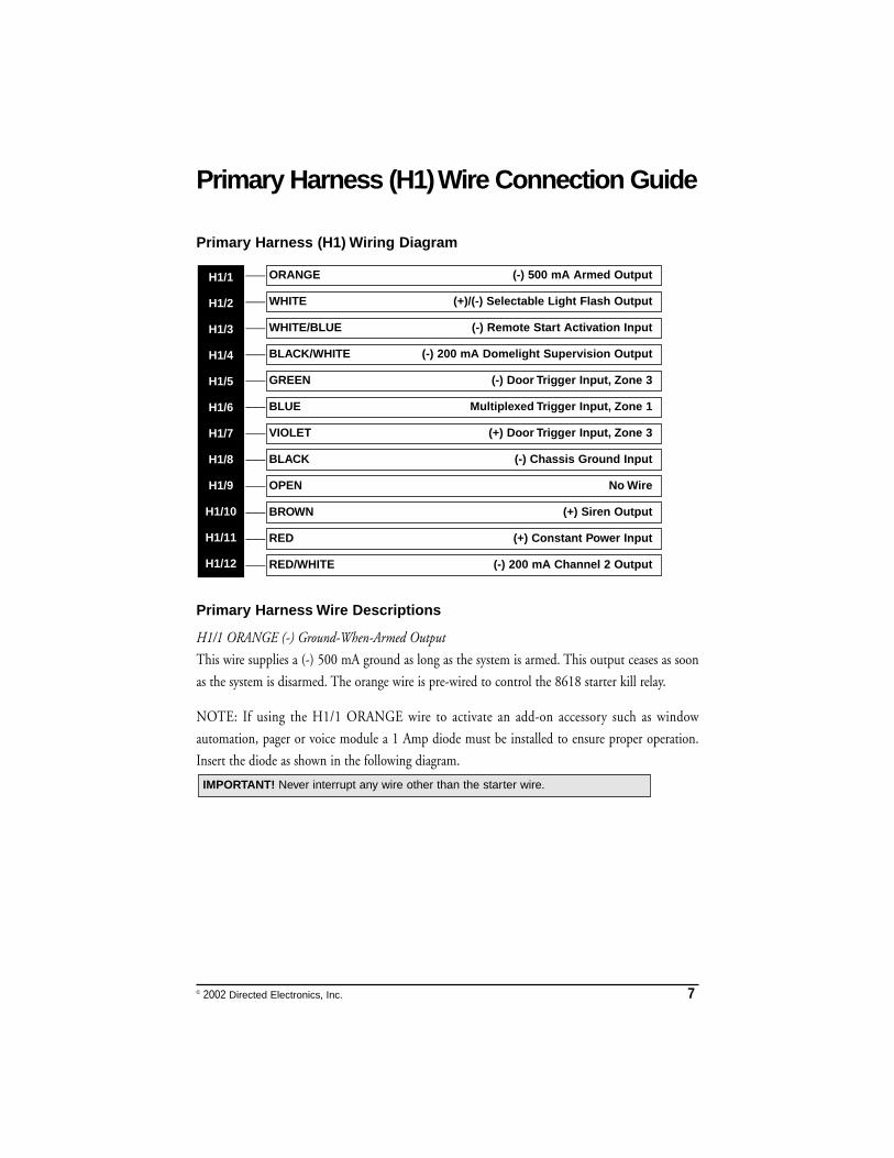
Primary Harness (H1) Wire Connection Guide
Primary Harness (H1) Wiring Diagram
___
___
___
___
___
___
___
___
___
___
___
___
Primary Harness Wire Descriptions
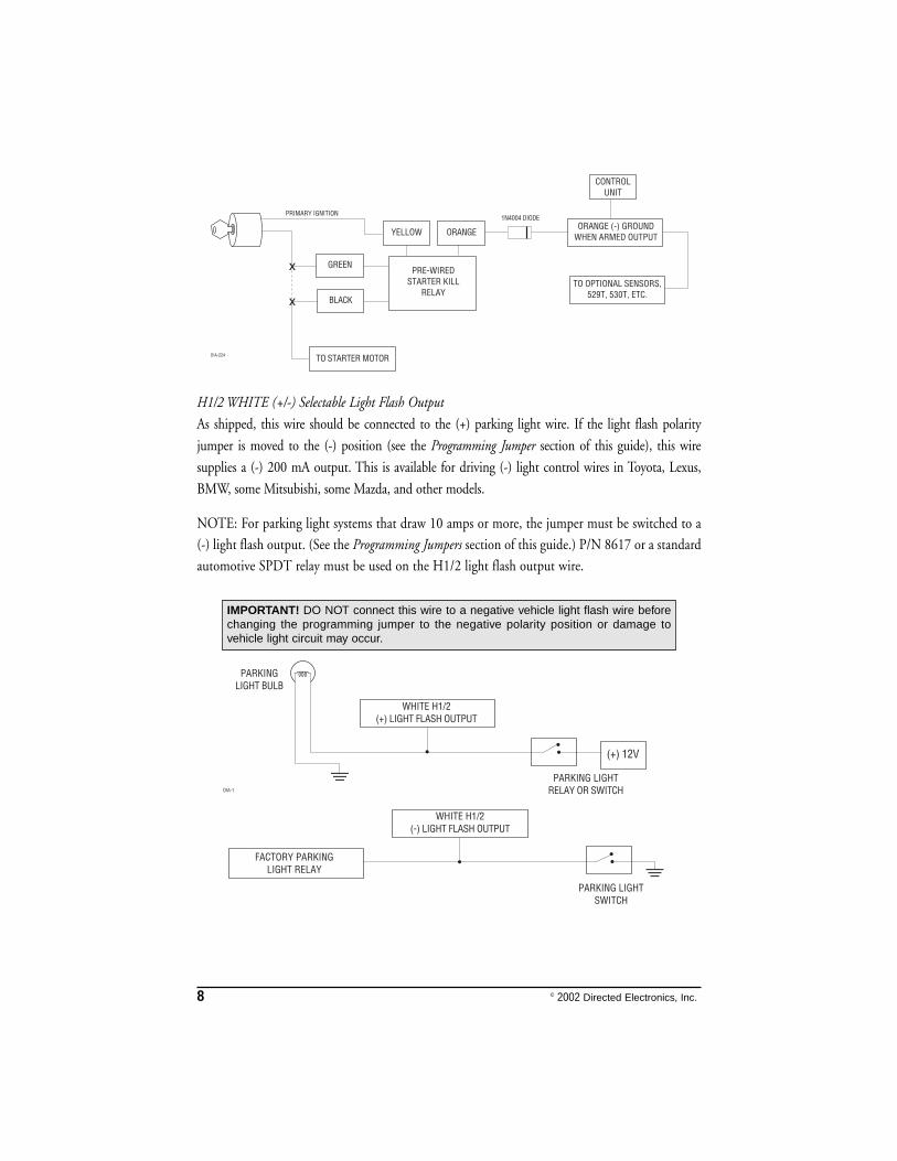
H1/1 ORANGE (-) Ground-When-Armed Output
This wire supplies a (-) 500 mA ground as long as the system is armed. This output ceases as soon
as the system is disarmed. The orange wire is pre-wired to control the 8618 starter kill relay.
NOTE: If using the H1/1 ORANGE wire to activate an add-on accessory such as window
automation, pager or voice module a 1 Amp diode must be installed to ensure proper operation.
Insert the diode as shown in the following diagram.
IMPORTANT! Never interrupt any wire other than the starter wire.
RED/WHITE (-) 200 mA Channel 2 Output
RED (+) Constant Power Input
BROWN (+) Siren Output
OPEN No Wire
BLACK (-) Chassis Ground Input
VIOLET (+) Door Trigger Input, Zone 3
BLUE Multiplexed Trigger Input, Zone 1
GREEN (-) Door Trigger Input, Zone 3
BLACK/WHITE (-) 200 mA Domelight Supervision Output
WHITE/BLUE (-) Remote Start Activation Input
WHITE (+)/(-) Selectable Light Flash Output
ORANGE (-) 500 mA Armed Output H1/1
H1/2
H1/3
H1/4
H1/5
H1/6
H1/7
H1/8
H1/9
H1/10
H1/11
H1/12
8 © 2002 Directed Electronics, Inc.
H1/2 WHITE (+/-) Selectable Light Flash Output
As shipped, this wire should be connected to the (+) parking light wire. If the light flash polarity
jumper is moved to the (-) position (see the Programming Jumper section of this guide), this wire
supplies a (-) 200 mA output. This is available for driving (-) light control wires in Toyota, Lexus,
BMW, some Mitsubishi, some Mazda, and other models.
NOTE: For parking light systems that draw 10 amps or more, the jumper must be switched to a
(-) light flash output. (See the Programming Jumpers section of this guide.) P/N 8617 or a standard
automotive SPDT relay must be used on the H1/2 light flash output wire.
IMPORTANT! DO NOT connect this wire to a negative vehicle light flash wire beforechanging the programming jumper to the negative polarity position or damage tovehicle light circuit may occur.
© 2002 Directed Electronics, Inc. 9
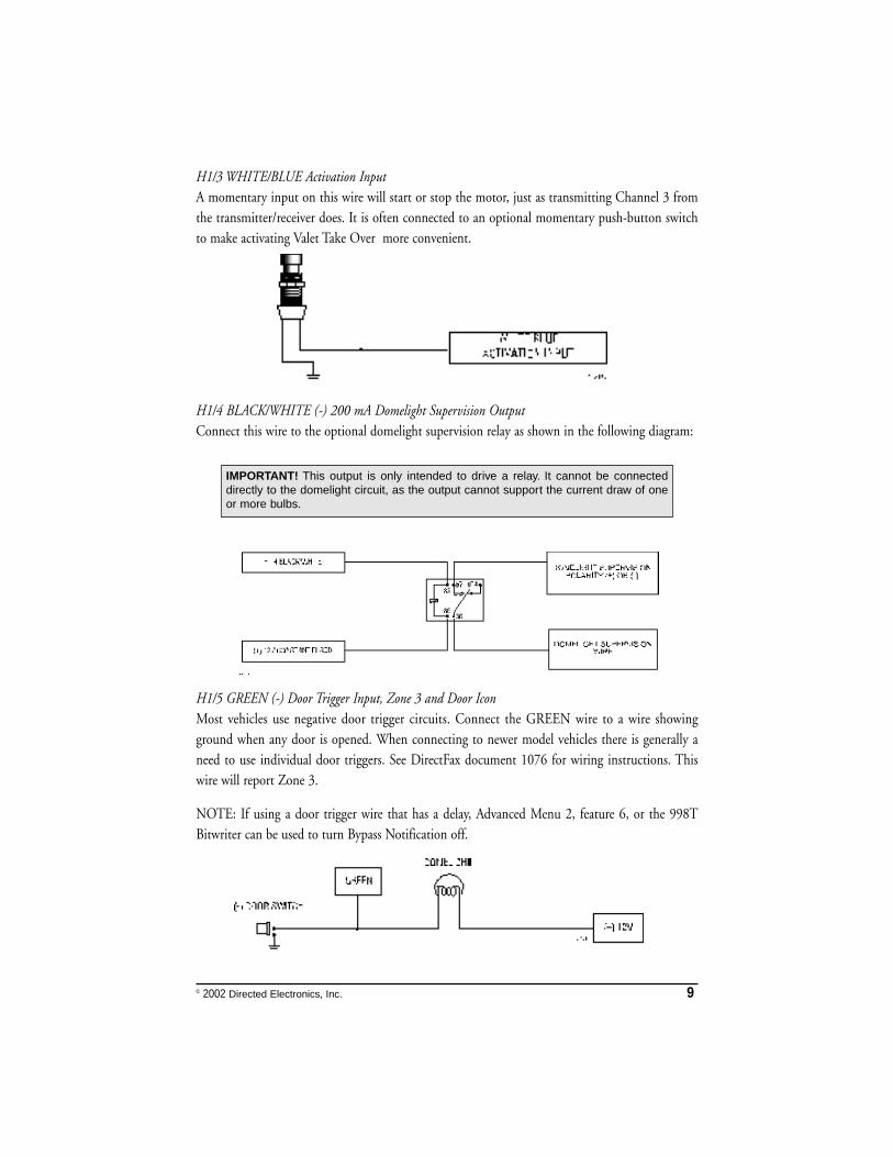
H1/3 WHITE/BLUE Activation InputA momentary input on this wire will start or stop the motor, just as transmitting Channel 3 fromthe transmitter/receiver does. It is often connected to an optional momentary push-button switchto make activating Valet Take Over more convenient.
H1/4 BLACK/WHITE (-) 200 mA Domelight Supervision OutputConnect this wire to the optional domelight supervision relay as shown in the following diagram:
H1/5 GREEN (-) Door Trigger Input, Zone 3 and Door IconMost vehicles use negative door trigger circuits. Connect the GREEN wire to a wire showingground when any door is opened. When connecting to newer model vehicles there is generally aneed to use individual door triggers. See DirectFax document 1076 for wiring instructions. Thiswire will report Zone 3.
NOTE: If using a door trigger wire that has a delay, Advanced Menu 2, feature 6, or the 998TBitwriter can be used to turn Bypass Notification off.
IMPORTANT! This output is only intended to drive a relay. It cannot be connecteddirectly to the domelight circuit, as the output cannot support the current draw of oneor more bulbs.
10 © 2002 Directed Electronics, Inc.
H1/6 BLUE (-) Multiplexed Trigger Input, Zone 1 and Trunk IconThis input will respond to a negative input with a WarnAway® or instant trigger. It is ideal for hoodand trunk pins and will report on Zone 1. It can also be used with Directed dual-stage sensors. TheH1/6 BLUE WarnAway® or instant trigger wire can also be used to shunt sensors during operation ofauxiliary channels or remote start. (See Bypassing Sensor Inputs section of this guide.)
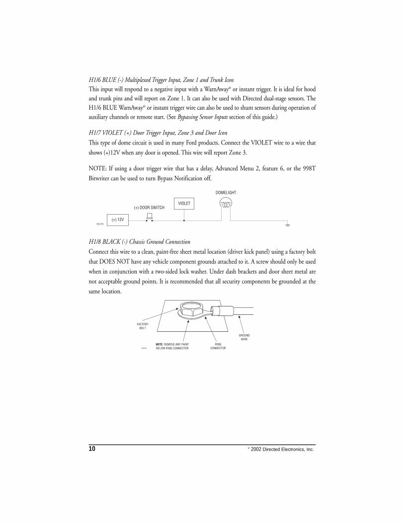
H1/7 VIOLET (+) Door Trigger Input, Zone 3 and Door Icon
This type of dome circuit is used in many Ford products. Connect the VIOLET wire to a wire that
shows (+)12V when any door is opened. This wire will report Zone 3.
NOTE: If using a door trigger wire that has a delay, Advanced Menu 2, feature 6, or the 998T
Bitwriter can be used to turn Bypass Notification off.
H1/8 BLACK (-) Chassis Ground Connection
Connect this wire to a clean, paint-free sheet metal location (driver kick panel) using a factory bolt
that DOES NOT have any vehicle component grounds attached to it. A screw should only be used
when in conjunction with a two-sided lock washer. Under dash brackets and door sheet metal are
not acceptable ground points. It is recommended that all security components be grounded at the
same location.
© 2002 Directed Electronics, Inc. 11
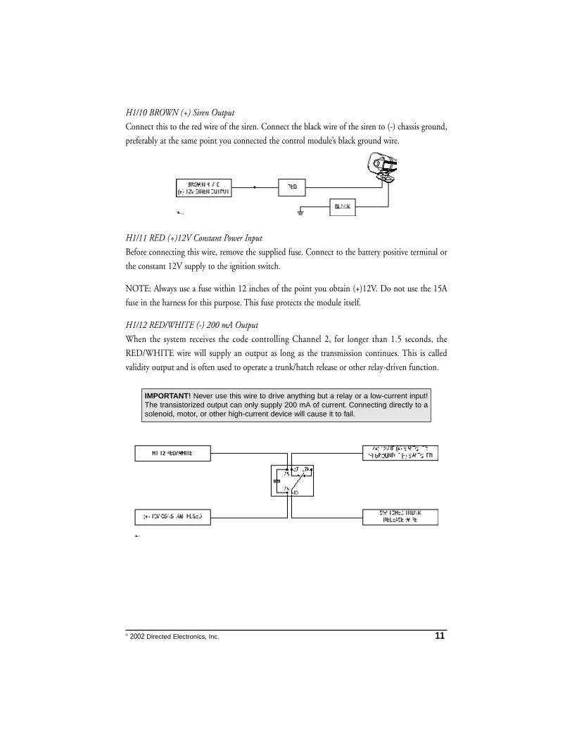
H1/10 BROWN (+) Siren Output
Connect this to the red wire of the siren. Connect the black wire of the siren to (-) chassis ground,
preferably at the same point you connected the control module’s black ground wire.
H1/11 RED (+)12V Constant Power Input
Before connecting this wire, remove the supplied fuse. Connect to the battery positive terminal or
the constant 12V supply to the ignition switch.
NOTE: Always use a fuse within 12 inches of the point you obtain (+)12V. Do not use the 15A
fuse in the harness for this purpose. This fuse protects the module itself.
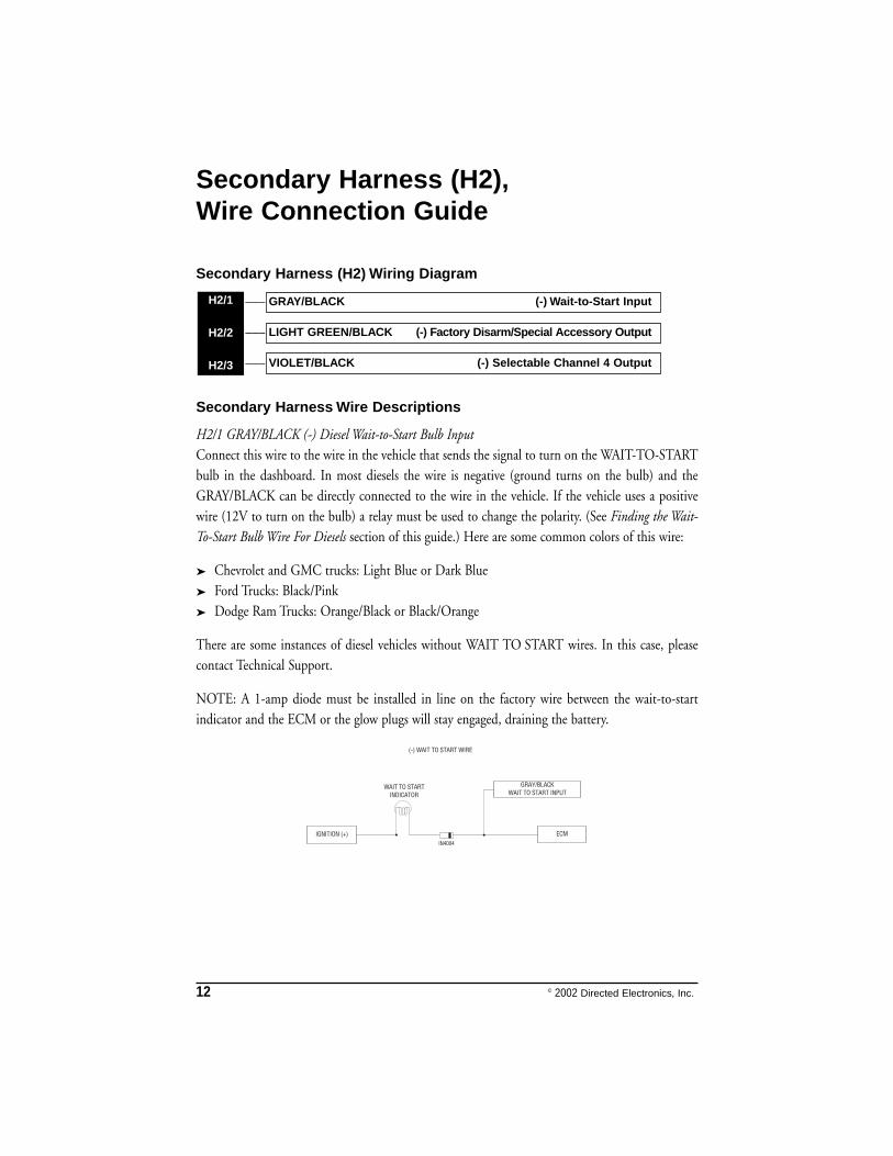
H1/12 RED/WHITE (-) 200 mA Output
When the system receives the code controlling Channel 2, for longer than 1.5 seconds, the
RED/WHITE wire will supply an output as long as the transmission continues. This is called
validity output and is often used to operate a trunk/hatch release or other relay-driven function.
IMPORTANT! Never use this wire to drive anything but a relay or a low-current input!The transistorized output can only supply 200 mA of current. Connecting directly to asolenoid, motor, or other high-current device will cause it to fail.
12 © 2002 Directed Electronics, Inc.
Secondary Harness (H2),Wire Connection Guide
Secondary Harness (H2) Wiring Diagram
___
___
___
Secondary Harness Wire Descriptions
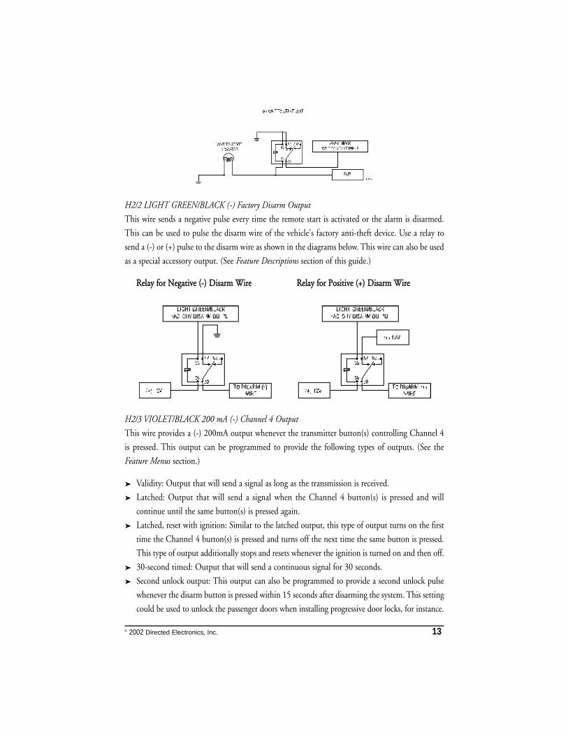
H2/1 GRAY/BLACK (-) Diesel Wait-to-Start Bulb InputConnect this wire to the wire in the vehicle that sends the signal to turn on the WAIT-TO-STARTbulb in the dashboard. In most diesels the wire is negative (ground turns on the bulb) and theGRAY/BLACK can be directly connected to the wire in the vehicle. If the vehicle uses a positivewire (12V to turn on the bulb) a relay must be used to change the polarity. (See Finding the Wait-To-Start Bulb Wire For Diesels section of this guide.) Here are some common colors of this wire:
➤ Chevrolet and GMC trucks: Light Blue or Dark Blue➤ Ford Trucks: Black/Pink➤ Dodge Ram Trucks: Orange/Black or Black/Orange
There are some instances of diesel vehicles without WAIT TO START wires. In this case, pleasecontact Technical Support.
NOTE: A 1-amp diode must be installed in line on the factory wire between the wait-to-startindicator and the ECM or the glow plugs will stay engaged, draining the battery.
VIOLET/BLACK (-) Selectable Channel 4 Output
LIGHT GREEN/BLACK (-) Factory Disarm/Special Accessory Output
GRAY/BLACK (-) Wait-to-Start InputH2/1
H2/2
H2/3
© 2002 Directed Electronics, Inc. 13
H2/2 LIGHT GREEN/BLACK (-) Factory Disarm Output
This wire sends a negative pulse every time the remote start is activated or the alarm is disarmed.
This can be used to pulse the disarm wire of the vehicle's factory anti-theft device. Use a relay to
send a (-) or (+) pulse to the disarm wire as shown in the diagrams below. This wire can also be used
as a special accessory output. (See Feature Descriptions section of this guide.)
RReellaayy ffoorr NNeeggaattiivvee ((--)) DDiissaarrmm WWiirree RReellaayy ffoorr PPoossiittiivvee ((++)) DDiissaarrmm WWiirree
H2/3 VIOLET/BLACK 200 mA (-) Channel 4 Output
This wire provides a (-) 200mA output whenever the transmitter button(s) controlling Channel 4
is pressed. This output can be programmed to provide the following types of outputs. (See the
Feature Menus section.)
➤ Validity: Output that will send a signal as long as the transmission is received.
➤ Latched: Output that will send a signal when the Channel 4 button(s) is pressed and will
continue until the same button(s) is pressed again.
➤ Latched, reset with ignition: Similar to the latched output, this type of output turns on the first
time the Channel 4 button(s) is pressed and turns off the next time the same button is pressed.
This type of output additionally stops and resets whenever the ignition is turned on and then off.
➤ 30-second timed: Output that will send a continuous signal for 30 seconds.
➤ Second unlock output: This output can also be programmed to provide a second unlock pulse
whenever the disarm button is pressed within 15 seconds after disarming the system. This setting
could be used to unlock the passenger doors when installing progressive door locks, for instance.
14 © 2002 Directed Electronics, Inc.
Relay Satellite Ignition Switch InterfaceWire Connection Guide
Heavy Gauge Relay Satellite Wiring Diagram
All except the red heavy gauge wires leading from the relay satellite are used to energize high current
circuits in the vehicle. It is crucial that these connections are made correctly so that they are capable
of handling the current demands. For this reason, scotch locks, T-taps and other such connectors
should not be used.
___
___
___
___
___
___
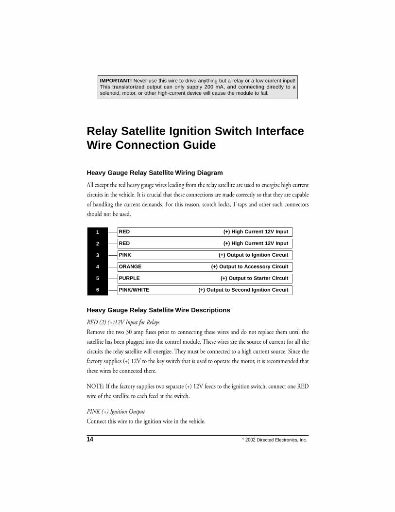
Heavy Gauge Relay Satellite Wire Descriptions
RED (2) (+)12V Input for Relays
Remove the two 30 amp fuses prior to connecting these wires and do not replace them until the
satellite has been plugged into the control module. These wires are the source of current for all the
circuits the relay satellite will energize. They must be connected to a high current source. Since the
factory supplies (+) 12V to the key switch that is used to operate the motor, it is recommended that
these wires be connected there.
NOTE: If the factory supplies two separate (+) 12V feeds to the ignition switch, connect one RED
wire of the satellite to each feed at the switch.
PINK (+) Ignition Output
Connect this wire to the ignition wire in the vehicle.
PINK/WHITE (+) Output to Second Ignition Circuit
PURPLE (+) Output to Starter Circuit
ORANGE (+) Output to Accessory Circuit
PINK (+) Output to Ignition Circuit
RED (+) High Current 12V Input
RED (+) High Current 12V Input1
2
3
4
5
6
IMPORTANT! Never use this wire to drive anything but a relay or a low-current input!This transistorized output can only supply 200 mA, and connecting directly to asolenoid, motor, or other high-current device will cause the module to fail.
© 2002 Directed Electronics, Inc. 15
ORANGE (+) Accessory Output
Connect this wire to the accessory wire in the vehicle that powers the climate control system.
PURPLE (+) Starter Output
Connect this wire to the starter wire in the vehicle.
NOTE: If failsafe starter kill is installed, be sure the PURPLE wire is connected to the car side of
the failsafe starter kill relay.
PINK/WHITE (+) Output to Second Ignition Circuit
Connect this wire to the second ignition wire in the vehicle.
NOTE: For vehicles that do not have a second ignition wire, this connection is not required.
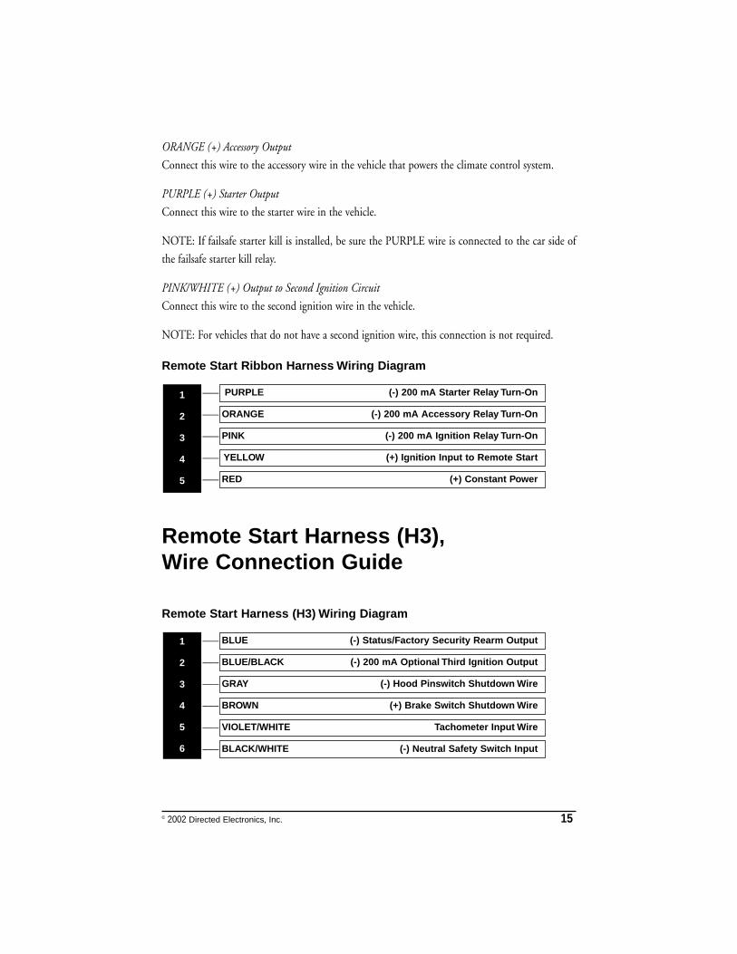
Remote Start Ribbon Harness Wiring Diagram
___
___
___
___
___
Remote Start Harness (H3),Wire Connection Guide
Remote Start Harness (H3) Wiring Diagram
___
___
___
___
___
___ BLACK/WHITE (-) Neutral Safety Switch Input
VIOLET/WHITE Tachometer Input Wire
BROWN (+) Brake Switch Shutdown Wire
GRAY (-) Hood Pinswitch Shutdown Wire
BLUE/BLACK (-) 200 mA Optional Third Ignition Output
BLUE (-) Status/Factory Security Rearm Output1
2
3
4
5
6
RED (+) Constant Power
YELLOW (+) Ignition Input to Remote Start
PINK (-) 200 mA Ignition Relay Turn-On
ORANGE (-) 200 mA Accessory Relay Turn-On
PURPLE (-) 200 mA Starter Relay Turn-On 1
2
3
4
5
16 © 2002 Directed Electronics, Inc.
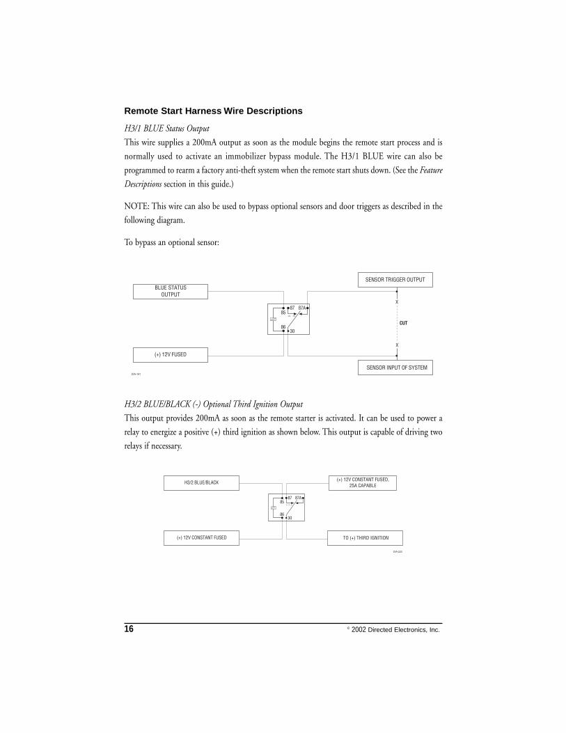
Remote Start Harness Wire Descriptions
H3/1 BLUE Status Output
This wire supplies a 200mA output as soon as the module begins the remote start process and is
normally used to activate an immobilizer bypass module. The H3/1 BLUE wire can also be
programmed to rearm a factory anti-theft system when the remote start shuts down. (See the Feature
Descriptions section in this guide.)
NOTE: This wire can also be used to bypass optional sensors and door triggers as described in the
following diagram.
To bypass an optional sensor:
H3/2 BLUE/BLACK (-) Optional Third Ignition Output
This output provides 200mA as soon as the remote starter is activated. It can be used to power a
relay to energize a positive (+) third ignition as shown below. This output is capable of driving two
relays if necessary.
© 2002 Directed Electronics, Inc. 17
H3/3 GRAY (-) Hood Pinswitch Input, Zone 6 and Hood Icon
This wire MUST be connected to hood pinswitch. This input will disable or shut down the remote
start when the hood is opened. It will also trigger the security system if the hood is opened while
the system is armed and report Zone 6.
H3/4 BROWN (+) Brake Switch Input
This wire MUST be connected to the vehicle's brake light wire. This is the wire that shows (+) 12V
when the brake pedal is pressed. The remote start will be disabled or shut down any time the brake
pedal is pressed.
H3/5 VIOLET/WHITE Tachometer Input
This input provides the module with information about the engine's revolutions per minute
(RPMs). It can be connected to the negative side of the coil in vehicles with conventional coils. In
multi-coil and high energy ignition systems locating a proper signal may be more difficult. (See
Installation Points to Remember section of this guide for finding the tachometer wire.) Once
connected, you must teach the system the tach signal. (See Tach Learning section of this guide.)
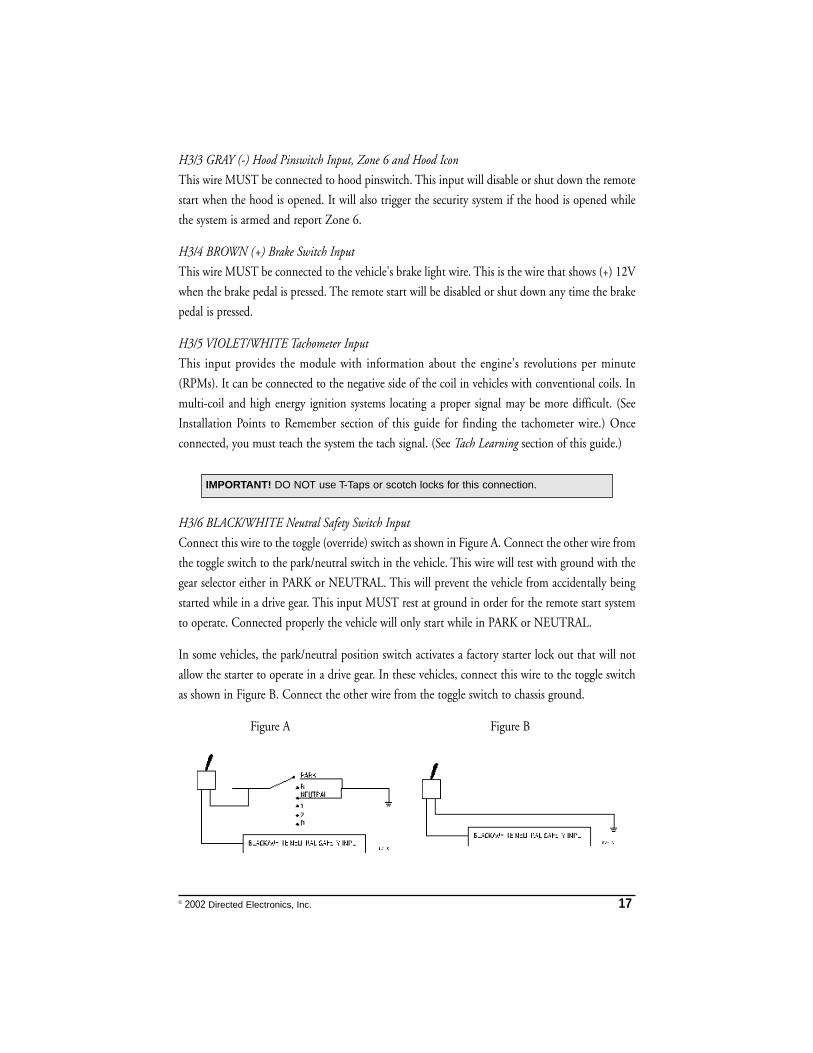
H3/6 BLACK/WHITE Neutral Safety Switch Input
Connect this wire to the toggle (override) switch as shown in Figure A. Connect the other wire from
the toggle switch to the park/neutral switch in the vehicle. This wire will test with ground with the
gear selector either in PARK or NEUTRAL. This will prevent the vehicle from accidentally being
started while in a drive gear. This input MUST rest at ground in order for the remote start system
to operate. Connected properly the vehicle will only start while in PARK or NEUTRAL.
In some vehicles, the park/neutral position switch activates a factory starter lock out that will not
allow the starter to operate in a drive gear. In these vehicles, connect this wire to the toggle switch
as shown in Figure B. Connect the other wire from the toggle switch to chassis ground.
Figure A Figure B
IMPORTANT! DO NOT use T-Taps or scotch locks for this connection.
18 © 2002 Directed Electronics, Inc.
Neutral Safety Switch Interface
Some vehicles combine the column shift mechanism and the mechanical neutral safety switch into
one mechanical part. In these vehicles, it is impossible to interface the remote start system before
the neutral safety switch. With this type of vehicle, if the vehicle is left in a drive gear and the remote
start system is activated, the vehicle will move and may cause damage to persons or property. The
following test must be performed before the vehicle is released to the customer.
NOTE: You must complete the remote start system installation before doing the following test.
Ensure that the remote start system is functioning normally. This includes connecting to the brake
as a shut-down.
Testing the Neutral Safety Switch
1. Make sure there is adequate clearance to the front and rear of the vehicle because it may move
slightly.
2. Make sure the hood is closed and there are no remote start shut-downs active.
3. Set the emergency brake.
4. Turn the key to the "run" position, this will release the shifter.
5. Place the car in drive (D).
6. Place your foot directly over the brake pedal, but do not depress it. Be ready to step on the brake
if the starter engages.
7. Activate the remote start system.
8. If the starter engages, immediately depress the brake to shut the remote start system down. If
the starter does not engage, no additional safety system is required.
If the starter engages while testing, refer to DirectFax Document 1008 (Neutral Safety Update). It is
available to authorized dealers only from the technical resources listed at the beginning of this manual.
IMPORTANT! Once the interface is complete, attempt to remote start the vehicle withthe door closed and the key in the ignition. The vehicle should not start. If it does,recheck the connections.
IMPORTANT! Always perform the Vehicle Safety Check section of this guide to verifythat the vehicle cannot be started in ANY drive gear and that the override switch isfunctioning properly.
© 2002 Directed Electronics, Inc. 19
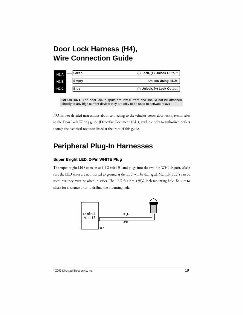
Door Lock Harness (H4),Wire Connection Guide
___
___
___
NOTE: For detailed instructions about connecting to the vehicle’s power door lock systems, refer
to the Door Lock Wiring guide (DirectFax Document 1041), available only to authorized dealers
though the technical resources listed at the front of this guide.
Peripheral Plug-In Harnesses
Super Bright LED, 2-Pin WHITE Plug
The super bright LED operates at (+) 2 volt DC and plugs into the two-pin WHITE port. Make
sure the LED wires are not shorted to ground as the LED will be damaged. Multiple LED’s can be
used, but they must be wired in series. The LED fits into a 9/32-inch mounting hole. Be sure to
check for clearance prior to drilling the mounting hole.
IMPORTANT! The door lock outputs are low current and should not be attacheddirectly to any high current device; they are only to be used to activate relays
Blue (-) Unlock, (+) Lock Output
Empty Unless Using 451M
Green (-) Lock, (+) Unlock OutputH2/A
H2/B
H2/C
20 © 2002 Directed Electronics, Inc.
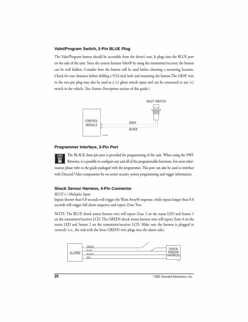
Valet/Program Switch, 2-Pin BLUE Plug
The Valet/Program button should be accessible from the driver’s seat. It plugs into the BLUE port
on the side of the unit. Since the system features Valet® by using the transmitter/receiver, the button
can be well hidden. Consider how the button will be used before choosing a mounting location.
Check for rear clearance before drilling a 9/32-inch hole and mounting the button.The GRAY wire
in the two-pin plug may also be used as a (+) ghost switch input and can be connected to any (+)
switch in the vehicle. (See Feature Descriptions section of this guide.)
Programmer Interface, 3-Pin Port
The BLACK three-pin port is provided for programming of the unit. When using the 998T
Bitwriter, it is possible to configure any and all of the programmable functions. For more infor-
mation please refer to the guide packaged with the programmer. This port can also be used to interface
with Directed Video components for on-screen security system programming and trigger information.
Shock Sensor Harness, 4-Pin ConnectorBLUE (-) Multiplex InputInputs shorter than 0.8 seconds will trigger the Warn Away® response, while inputs longer than 0.8seconds will trigger full alarm sequence and report Zone Two.
NOTE: The BLUE shock sensor harness wire will report Zone 2 on the status LED and Sensor 1on the transmitter/receiver LCD. The GREEN shock sensor harness wire will report Zone 4 on thestatus LED and Sensor 2 on the transmitter/receiver LCD. Make sure the harness is plugged incorrectly (i.e., the end with the loose GREEN wire plugs into the alarm side).
© 2002 Directed Electronics, Inc. 21
GREEN (-) Multiplex InputIf installing an optional Directed dual-stage sensor, connect to the GREEN wire off the shocksensor harness.
RED and BLACK: RED is (+)12V Constant, BLACK is (-) GroundDo not use these for anything besides the plug-in shock sensor.
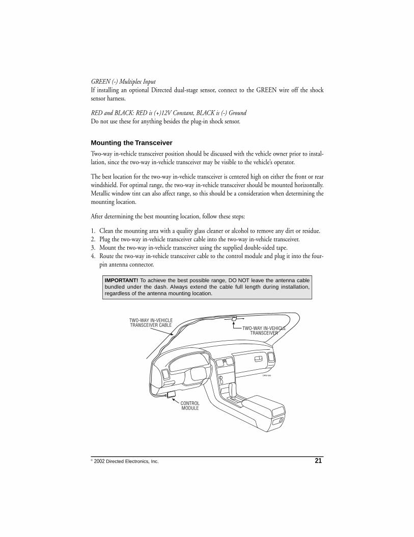
Mounting the Transceiver
Two-way in-vehicle transceiver position should be discussed with the vehicle owner prior to instal-lation, since the two-way in-vehicle transceiver may be visible to the vehicle’s operator.
The best location for the two-way in-vehicle transceiver is centered high on either the front or rearwindshield. For optimal range, the two-way in-vehicle transceiver should be mounted horizontally.Metallic window tint can also affect range, so this should be a consideration when determining themounting location.
After determining the best mounting location, follow these steps:
1. Clean the mounting area with a quality glass cleaner or alcohol to remove any dirt or residue. 2. Plug the two-way in-vehicle transceiver cable into the two-way in-vehicle transceiver.3. Mount the two-way in-vehicle transceiver using the supplied double-sided tape. 4. Route the two-way in-vehicle transceiver cable to the control module and plug it into the four-
pin antenna connector.
������������� ������ ����
�����������
������������� ������ ����� ����
�������
IMPORTANT! To achieve the best possible range, DO NOT leave the antenna cablebundled under the dash. Always extend the cable full length during installation,regardless of the antenna mounting location.
22 © 2002 Directed Electronics, Inc.
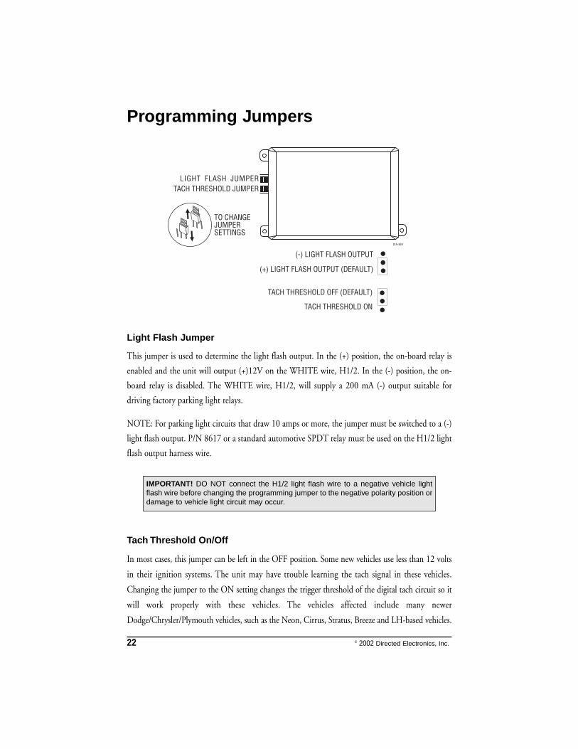
Programming Jumpers
Light Flash Jumper
This jumper is used to determine the light flash output. In the (+) position, the on-board relay is
enabled and the unit will output (+)12V on the WHITE wire, H1/2. In the (-) position, the on-
board relay is disabled. The WHITE wire, H1/2, will supply a 200 mA (-) output suitable for
driving factory parking light relays.
NOTE: For parking light circuits that draw 10 amps or more, the jumper must be switched to a (-)
light flash output. P/N 8617 or a standard automotive SPDT relay must be used on the H1/2 light
flash output harness wire.
Tach Threshold On/Off
In most cases, this jumper can be left in the OFF position. Some new vehicles use less than 12 volts
in their ignition systems. The unit may have trouble learning the tach signal in these vehicles.
Changing the jumper to the ON setting changes the trigger threshold of the digital tach circuit so it
will work properly with these vehicles. The vehicles affected include many newer
Dodge/Chrysler/Plymouth vehicles, such as the Neon, Cirrus, Stratus, Breeze and LH-based vehicles.
IMPORTANT! DO NOT connect the H1/2 light flash wire to a negative vehicle lightflash wire before changing the programming jumper to the negative polarity position ordamage to vehicle light circuit may occur.
© 2002 Directed Electronics, Inc. 23
System Features Learn Routine
The System Features Learn Routine dictates how the unit operates. Due to the number of steps,
they have been broken up into three menus. It is possible to access and change any of the feature
settings using the Valet/Program switch. However, this process can be greatly simplified by using the
998T Bitwriter. Any of the settings can be changed and then assigned to a particular transmitter, up
to four, a feature called Owner Recognition. Each time that particular transmitter is used to disarm
the system, the assigned feature settings will be recalled. Owner Recognition is only possible when
programming the unit via the 998T Bitwriter.
If the system was previously programmed using the 998T Bitwriter, the learn routine may be
locked. If the siren generates one long chirp when attempting to program the unit, the learn routine
is locked and must be unlocked using the 998T Bitwriter.
1. OOppeenn aa ddoooorr.. (The H1/5 GREEN wire or the H1/7 VIOLET wire must be
connected.)
2. IIggnniittiioonn.. Turn the ignition on, then back off: (The heavy gauge PINK wire of
the relay satellite must be connected.)
3. SSeelleecctt aa MMeennuu.. Press and HOLD the Valet/Program switch. (The
Valet/Program switch must be plugged into the BLUE port.) After three
seconds the siren will chirp once indicating entry to the Basic Features Menu.
If this is the menu you wish to access, release the button and go on to Step 4.
If the button is not released, you will jump to the next menu and the siren will
chirp twice. There are three possible menus. Once you have selected the desired
menu, release the Valet/Program switch.
4. SSeelleecctt aa FFeeaattuurree.. Press and release the Valet/Program switch the number of
times corresponding to the feature you wish to change. For example, to access
the third feature, press and release the switch three times. Then press the switch
once more and HOLD it. The siren will chirp the number of times equal to
the feature you have accessed.
24 © 2002 Directed Electronics, Inc.
5. PPrrooggrraamm tthhee FFeeaattuurree.. While HOLDING the Valet/Program switch, you can
toggle the feature on and off using the transmitter/receiver. Pressing the lock
button will select the one chirp setting. Pressing the unlock button will select
the two chirp setting. (See System Features Menus section of this guide.)
NOTE: Some features have more than two settings. Pressing the lock button
selects the one-chirp setting; pressing the unlock button will cycle through all
possible two-chirp settings.
6. RReelleeaassee tthhee VVaalleett//PPrrooggrraamm SSwwiittcchh..
Once a feature is programmed:
➤➤ Other features can be programmed within the same menu.
➤➤ Another menu can be selected.
➤➤ The learn routine can be exited if programming is complete.
To access another feature in the same menu:
1. Press and release the Valet/Program switch the number of times necessary to advance from the
feature you just programmed to the next one you want to program.
2. Then press the Valet/Program switch once more and HOLD it.
For example, if you just programmed the third feature in the menu and you would like to program
the seventh feature in the menu, you would press and release the Valet/Program switch four times
and then press it once more and HOLD it. The siren would chirp seven times to confirm access to
the seventh feature.
To select another menu:
1. Press and HOLD the Valet/Program switch.
2. After three seconds, the unit will advance to the next menu and the siren will chirp, indicating
which menu has been accessed.
For instance, if you just programmed some features in Menu #1 (Basic Features) and you wish to
program a feature in Menu #2, you press and HOLD the Valet/Program button. After three
seconds, the siren chirps twice indicating access to Menu #2.
To exit the learn routine do one of the following:
➤➤ Close the open door.
➤➤ Turn the ignition on.
© 2002 Directed Electronics, Inc. 25
➤➤ No activity for longer than 15 seconds.
➤➤ Press the Valet/Program switch too many times.
System Features Menus
Items in bold text have been programmed to the default setting at the factory.
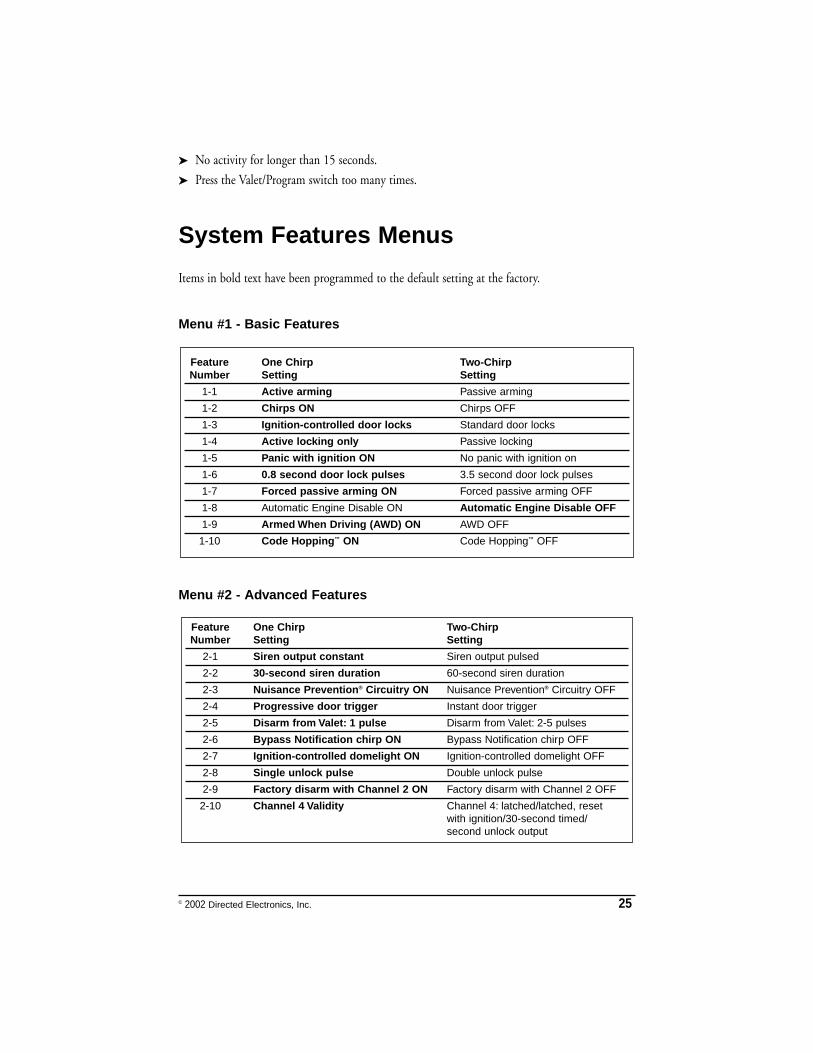
Menu #1 - Basic Features
Menu #2 - Advanced Features
Feature One Chirp Two-Chirp Number Setting Setting
2-1 Siren output constant Siren output pulsed
2-2 30-second siren duration 60-second siren duration
2-3 Nuisance Prevention® Circuitry ON Nuisance Prevention® Circuitry OFF
2-4 Progressive door trigger Instant door trigger
2-5 Disarm from Valet: 1 pulse Disarm from Valet: 2-5 pulses
2-6 Bypass Notification chirp ON Bypass Notification chirp OFF
2-7 Ignition-controlled domelight ON Ignition-controlled domelight OFF
2-8 Single unlock pulse Double unlock pulse
2-9 Factory disarm with Channel 2 ON Factory disarm with Channel 2 OFF
2-10 Channel 4 Validity Channel 4: latched/latched, reset with ignition/30-second timed/second unlock output
Feature One Chirp Two-Chirp Number Setting Setting
1-1 Active arming Passive arming
1-2 Chirps ON Chirps OFF
1-3 Ignition-controlled door locks Standard door locks
1-4 Active locking only Passive locking
1-5 Panic with ignition ON No panic with ignition on
1-6 0.8 second door lock pulses 3.5 second door lock pulses
1-7 Forced passive arming ON Forced passive arming OFF
1-8 Automatic Engine Disable ON Automatic Engine Disable OFF
1-9 Armed When Driving (AWD) ON AWD OFF
1-10 Code Hopping™ ON Code Hopping™ OFF
26 © 2002 Directed Electronics, Inc.
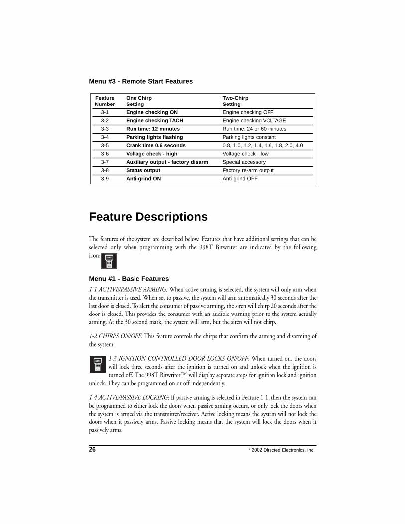
Menu #3 - Remote Start Features
Feature Descriptions
The features of the system are described below. Features that have additional settings that can beselected only when programming with the 998T Bitwriter are indicated by the followingicon:
Menu #1 - Basic Features
1-1 ACTIVE/PASSIVE ARMING: When active arming is selected, the system will only arm whenthe transmitter is used. When set to passive, the system will arm automatically 30 seconds after thelast door is closed. To alert the consumer of passive arming, the siren will chirp 20 seconds after thedoor is closed. This provides the consumer with an audible warning prior to the system actuallyarming. At the 30 second mark, the system will arm, but the siren will not chirp.
1-2 CHIRPS ON/OFF: This feature controls the chirps that confirm the arming and disarming ofthe system.
1-3 IGNITION CONTROLLED DOOR LOCKS ON/OFF: When turned on, the doorswill lock three seconds after the ignition is turned on and unlock when the ignition isturned off. The 998T Bitwriter™ will display separate steps for ignition lock and ignition
unlock. They can be programmed on or off independently.
1-4 ACTIVE/PASSIVE LOCKING: If passive arming is selected in Feature 1-1, then the system canbe programmed to either lock the doors when passive arming occurs, or only lock the doors whenthe system is armed via the transmitter/receiver. Active locking means the system will not lock thedoors when it passively arms. Passive locking means that the system will lock the doors when itpassively arms.
Feature One Chirp Two-Chirp Number Setting Setting
3-1 Engine checking ON Engine checking OFF
3-2 Engine checking TACH Engine checking VOLTAGE
3-3 Run time: 12 minutes Run time: 24 or 60 minutes
3-4 Parking lights flashing Parking lights constant
3-5 Crank time 0.6 seconds 0.8, 1.0, 1.2, 1.4, 1.6, 1.8, 2.0, 4.0
3-6 Voltage check - high Voltage check - low
3-7 Auxiliary output - factory disarm Special accessory
3-8 Status output Factory re-arm output
3-9 Anti-grind ON Anti-grind OFF
© 2002 Directed Electronics, Inc. 27
NOTE: Remember, when passive arming is selected, the unit will chirp 20 seconds after the last
door is closed. The system does not actually arm or lock the doors until 30 seconds after the door
has been closed.
1-5 PANIC WITH IGNITION ON: This feature controls whether or not the panic mode is
available with the ignition on. In some states, there are laws prohibiting a siren sounding in a
moving vehicle. This feature makes the system compliant with these regulations.
1-6 DOOR LOCK PULSE DURATlON: Some European vehicles require longer lock and unlock
pulses to operate the vacuum pump. Programming the system to provide 3.5 second pulses, will accom-
modate the door lock interface in these vehicles. The default setting is 0.8 second door lock pulses.
1-7 FORCED PASSIVE ARMING ON/OFF: To use this feature, passive arming must be selected in
Feature 1-1. When turned on, forced passive arming will ensure that the system will passively arm,
even if a zone is left open or invalid. Forced passive arming occurs one hour after the ignition is
turned off.
1-8 AUTOMATIC ENGINE DISABLE (AED) ON/OFF: AED is a full-time, passive starter disable
that works independently of the security system. When turned on, the orange, ground-when-armed
output (H1/1) will activate 30 seconds after the ignition is turned off. The LED will flash at half its
normal rate when the ignition is turned off to indicate that AED is active and will interrupt the
starter in 30 seconds. AED does not occur in Valet® mode and can be bypassed using the
emergency override procedure. The transmitter can be used to disarm AED.
1-9 ARMED WHILE DRIVING (AWD) ON/OFF: In the default setting (Armed While Driving),
the system can be armed with the ignition on. When armed, the ground-when-armed is not active
and the sensors are bypassed. The door triggers will remain active.
1-10 CODE HOPPING™ ON/OFF: The system uses a mathematical formula to change its code
each time the transmitter and receiver communicate. This makes the group of bits or "word" from
the transmitter very long. The longer the word is, the easier it is to block its transmission to the unit.
Disabling the Code Hopping™ feature lets the receiver ignore the Code Hopping™ part of the
transmitted word. As a result, the unit may have better range with Code Hopping™ off.
28 © 2002 Directed Electronics, Inc.
Menu #2 - Advanced Features
2-1 SIREN OUTPUT CONSTANT/PULSED: The system can be programmed to output pulses
instead of a continuous output when the system is triggered. This is useful to honk the factory horn
in applications where a siren is undesirable. Remember that the unit is only capable of supplying 1
amp of current. A relay will be required to interface with most factory horn systems.
2-2 SIREN DURATION 30/60 SECONDS: It is possible to program the unit to sound for
30 or 60 seconds during the triggered sequence. Some states have laws regulating how long
a security system can sound. When using the 998T Bitwriter™, the siren can be programmed to
sound for any length of time from 1 second to 180 seconds.
2-3 NUISANCE PREVENTION CIRCUITRY™ (NPC™) ON/OFF: NPC™ stops repeated
triggering of the same zone. If one zone is triggered three times in one hour, that zone is bypassed
for one hour, starting from the time of the third trigger. During that hour, if the system sees a trigger
on that zone again, the system resets the one hour timer. If one hour passes and the zone has not
triggered again, the zone is activated and can trigger the system again. NPC™ only monitors sensor
inputs, and does not bypass the door trigger or the ignition trigger at any time. If NPC™ is turned
off, the system will respond to repeated triggers on the sensor inputs and will do so indefinitely.
Some states have laws regulating how many times a security system can trigger before it is considered
a nuisance and the vehicle is towed away.
2-4 PROGRESSIVE DOOR TRIGGER ON/OFF: The system responds to a door trigger input with
a progressive response. When the door is opened with the system armed, the siren will chirp 10
times prior to the full triggered sequence. The door trigger is still treated as an instant trigger and
closing the door quickly will not prevent full triggered sequence from occurring. If the progressive
door trigger is programmed off, the full siren output will occur the moment the door is opened.
2-5 VALET PULSE COUNT 1 TO 5 PULSES: The system can be programmed to count the
number of presses of the valet switch before disarming the security system. The factory default
setting is one pulse. The unit can also be set for two to five pulses.
Ghost Switch option: For added security, the GRAY wire on the two-pin Valet®/Program plug can
be connected to any switch in the vehicle that provides a positive (+) momentary pulse.
2-6 BYPASS NOTIFICATION CHIRP ON/OFF: When programmed on, any active zone input to
the system during arming will generate a bypass notification chirp. When programmed OFF, no
bypass notification chirps will be generated if any zone is active during arming.
© 2002 Directed Electronics, Inc. 29
2-7 IGNITION CONTROLLED DOME LIGHT SUPERVISION ON/OFF: If turned on, thesystem will turn on the dome light for 60 seconds when the ignition is turned off. The optionaldome light supervision feature must be installed as described in the Wire Connection Guide.
2-8 DOUBLE PULSE UNLOCK ON/OFF: Some vehicles require two pulses on a single wire tounlock the doors. When the double pulse unlock feature is turned on, the BLUE H4/C wire willsupply two negative pulses instead of a single pulse. At the same time, the GREEN H4/A wire willsupply two positive pulses instead of a single pulse. This makes it possible to directly interface withdouble pulse vehicles without any extra parts.
2-9 FACTORY ALARM DISARM WITH CHANNEL 2: In the default setting the factory alarmdisarm output will disarm the factory alarm system any time the button(s) controlling Channel Twois pressed.
2-10 CHANNEL 4 VALIDITY/LATCHED/LATCHED RESET WITH IGNITION/30 SECONDTIMED/SECOND UNLOCK OUTPUT: Channel Four can be programmed for these outputconfigurations. The unit is set to the default validity output. To change the configuration, use thetwo-chirp setting to toggle through the different configurations.
Menu #3 - Remote Start Features
3-1 ENGINE CHECKING ON/OFF: In the default setting the remote start will monitor either thevehicle's tach wire or voltage depending on the programming of feature 3-2. If programmed OFFthe vehicle will crank for the programmed crank time (feature 3-5) and will not verify with tach orvoltage that the car is running. In the OFF setting, if the vehicle fails to start, the ignition can stayon for the entire run duration. Using tach or voltage check is always recommended if possible.
NOTE: This feature is for testing purposes only. Always use Tach or voltage sensing beforecompleting the installation.
3-2 CHECKING TYPE TACH/VOLTAGE: Selects the method of engine monitoring. If set toTACHOMETER the unit will reference the learned tach signal to disengage the starter. In additionit will monitor the RPM and shut down if the engine RPM is too high or too low. When set toVOLTAGE, the unit will crank the starter for the programmed time and then attempt to sense thatthe engine is running by detecting an increase in voltage. The threshold for the voltage check isselectable in feature 3-6.
3-3 RUN TIME 12, 24, 60 MINUTES: Selects the time in minutes that the system willoperate the engine until the system "times out". This is the maximum operation period andthe system may be shut down using a shutdown at any time. Using the 998T Bitwriter, the
run time can be programmed for any duration from 1-60 minutes.
3-4 PARKING LIGHTS FLASHING/CONSTANT: In the default setting, the unit will flash thevehicle's parking lights (if connected) while remote started. The constant setting will turn theparking lights on solid for the entire run duration.
30 © 2002 Directed Electronics, Inc.
3-5 CRANK TIME 0.6/0.8/1.0/1.2/1.4/1.6/1.8/2.0/4.0 SECONDS: If the unit is programmed forno engine checking or voltage sense, the crank time must be set to the appropriate duration. Thedefault setting is 0.6 second. If a different crank time is desired, select feature 3-5 and select either0.6 second by using the one-chirp setting or toggle through the higher settings by using the two-chirp settings.
3-6 VOLTAGE CHECK HI/LOW: This feature only functions when programmed for voltage sense.Some vehicles have many accessories, which are turned on when remote started. In these vehicles,the variation of voltage between the engine off and the car running is very small and the remotestart unit may "think" the vehicle has not started. This can cause the remote start to shut-down afterthe car has been started. If this happens program this feature to the LOW position.
3-7 AUXILIARY OUTPUT FACTORY DISARM/SPECIAL ACCESSORY: In the default setting theLT. GREEN/BLACK, H2/2, wire sends a negative pulse that may be used to disarm the vehicle’sfactory security system. If programmed for a special accessory, the wire can be used to energize arelay to power up extra ignition wires in the vehicle. This wire must be used to energize circuits inthe vehicle that operate accessories, such as the radio or heater.
3-8 BLUE WIRE STATUS OUTPUT/FACTORY SECURITY RE-ARM OUTPUT: The blue(H3/1) wire will supply a 200mA (-) output for the entire remote start run time. If programmedfor factory re-arm output, this wire will supply a momentary 200mA (-) pulse whenever the remotestart times out or is shut down with the transmitter. This can be used to re-arm many factorysecurity systems.
3-9 AUTOMATIC ANTI-GRIND ON/OFF: With the anti-grind ON (default) the ground-when-armed output will be active during remote start operation. If accessories such as a voice module orwindow module are added to the unit, it may be necessary to program this feature OFF.
Transmitter/Receiver Learn RoutineNOTE: For information regarding transmitter programming please refer to the Owner’s Guide.
The system comes with one transmitter that has been taught to the receiver. The receiver can storeup to four different transmitter codes in memory. Use the following learn routine to add trans-mitters to the system or to change button assignments if desired.
If the system was previously programmed using the 998T Bitwriter, the learn routine may belocked. If the siren generates one long chirp when attempting to program the unit, the learn routineis locked and must be unlocked using the 998T Bitwriter.
1. OOppeenn aa ddoooorr.. (The H1/5 GREEN wire or the H1/7 VIOLET wire mustbe connected.)
© 2002 Directed Electronics, Inc. 31
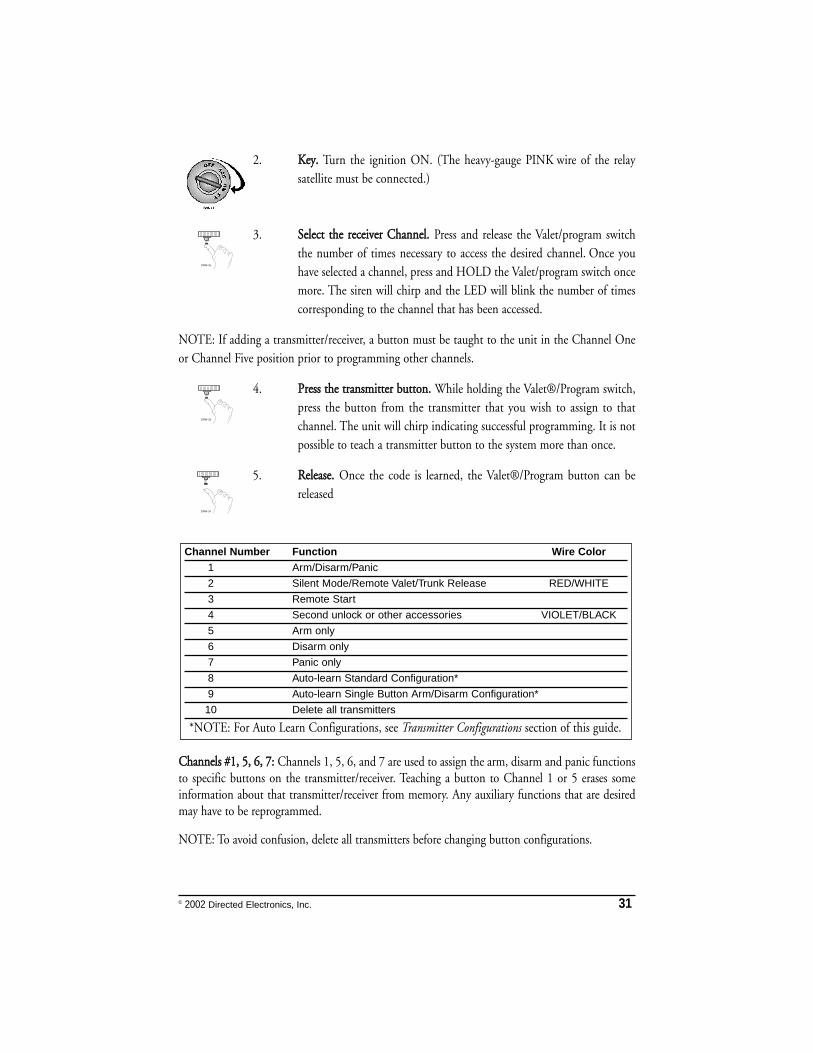
2. KKeeyy.. Turn the ignition ON. (The heavy-gauge PINK wire of the relaysatellite must be connected.)
3. SSeelleecctt tthhee rreecceeiivveerr CChhaannnneell.. Press and release the Valet/program switchthe number of times necessary to access the desired channel. Once youhave selected a channel, press and HOLD the Valet/program switch oncemore. The siren will chirp and the LED will blink the number of timescorresponding to the channel that has been accessed.
NOTE: If adding a transmitter/receiver, a button must be taught to the unit in the Channel Oneor Channel Five position prior to programming other channels.
4. PPrreessss tthhee ttrraannssmmiitttteerr bbuuttttoonn.. While holding the Valet®/Program switch,press the button from the transmitter that you wish to assign to thatchannel. The unit will chirp indicating successful programming. It is notpossible to teach a transmitter button to the system more than once.
5. RReelleeaassee.. Once the code is learned, the Valet®/Program button can bereleased
CChhaannnneellss ##11,, 55,, 66,, 77:: Channels 1, 5, 6, and 7 are used to assign the arm, disarm and panic functionsto specific buttons on the transmitter/receiver. Teaching a button to Channel 1 or 5 erases someinformation about that transmitter/receiver from memory. Any auxiliary functions that are desiredmay have to be reprogrammed.
NOTE: To avoid confusion, delete all transmitters before changing button configurations.
Channel Number Function Wire Color1 Arm/Disarm/Panic
2 Silent Mode/Remote Valet/Trunk Release RED/WHITE
3 Remote Start
4 Second unlock or other accessories VIOLET/BLACK
5 Arm only
6 Disarm only
7 Panic only
8 Auto-learn Standard Configuration*
9 Auto-learn Single Button Arm/Disarm Configuration*
10 Delete all transmitters
**NOTE: For Auto Learn Configurations, see Transmitter Configurations section of this guide.
32 © 2002 Directed Electronics, Inc.
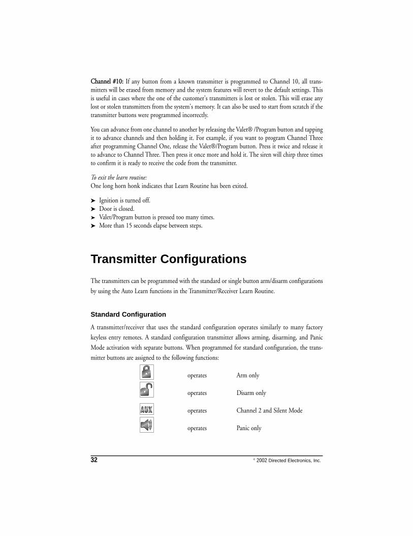
CChhaannnneell ##1100:: If any button from a known transmitter is programmed to Channel 10, all trans-mitters will be erased from memory and the system features will revert to the default settings. Thisis useful in cases where the one of the customer's transmitters is lost or stolen. This will erase anylost or stolen transmitters from the system's memory. It can also be used to start from scratch if thetransmitter buttons were programmed incorrectly.
You can advance from one channel to another by releasing the Valet® /Program button and tappingit to advance channels and then holding it. For example, if you want to program Channel Threeafter programming Channel One, release the Valet®/Program button. Press it twice and release itto advance to Channel Three. Then press it once more and hold it. The siren will chirp three timesto confirm it is ready to receive the code from the transmitter.
To exit the learn routine:One long horn honk indicates that Learn Routine has been exited.
➤➤ Ignition is turned off.➤➤ Door is closed.➤ Valet/Program button is pressed too many times.➤➤ More than 15 seconds elapse between steps.
Transmitter Configurations
The transmitters can be programmed with the standard or single button arm/disarm configurations
by using the Auto Learn functions in the Transmitter/Receiver Learn Routine.
Standard Configuration
A transmitter/receiver that uses the standard configuration operates similarly to many factory
keyless entry remotes. A standard configuration transmitter allows arming, disarming, and Panic
Mode activation with separate buttons. When programmed for standard configuration, the trans-
mitter buttons are assigned to the following functions:
operates Arm only
operates Disarm only
operates Channel 2 and Silent Mode
operates Panic only
© 2002 Directed Electronics, Inc. 33
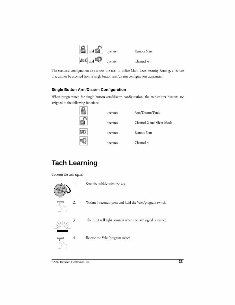
and operate Remote Start
and operate Channel 4
The standard configuration also allows the user to utilize Multi-Level Security Arming, a feature
that cannot be accessed from a single button arm/disarm configuration transmitter.
Single Button Arm/Disarm Configuration
When programmed for single button arm/disarm configuration, the transmitter buttons are
assigned to the following functions:
operates Arm/Disarm/Panic
operates Channel 2 and Silent Mode
operates Remote Start
operates Channel 4
Tach LearningTToo lleeaarrnn tthhee ttaacchh ssiiggnnaall::
1. Start the vehicle with the key.
2. Within 5 seconds, press and hold the Valet/program switch.
3. The LED will light constant when the tach signal is learned.
4. Release the Valet/program switch.
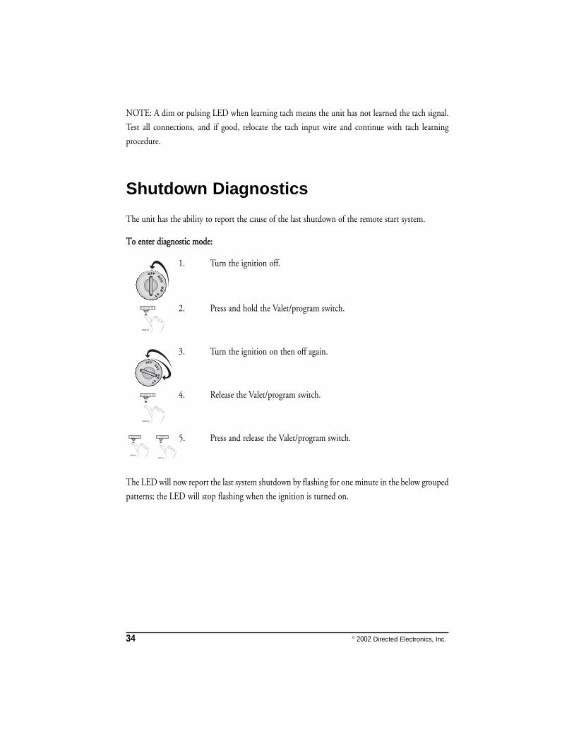
NOTE: A dim or pulsing LED when learning tach means the unit has not learned the tach signal.
Test all connections, and if good, relocate the tach input wire and continue with tach learning
procedure.
Shutdown Diagnostics
The unit has the ability to report the cause of the last shutdown of the remote start system.
TToo eenntteerr ddiiaaggnnoossttiicc mmooddee::
1. Turn the ignition off.
2. Press and hold the Valet/program switch.
3. Turn the ignition on then off again.
4. Release the Valet/program switch.
5. Press and release the Valet/program switch.
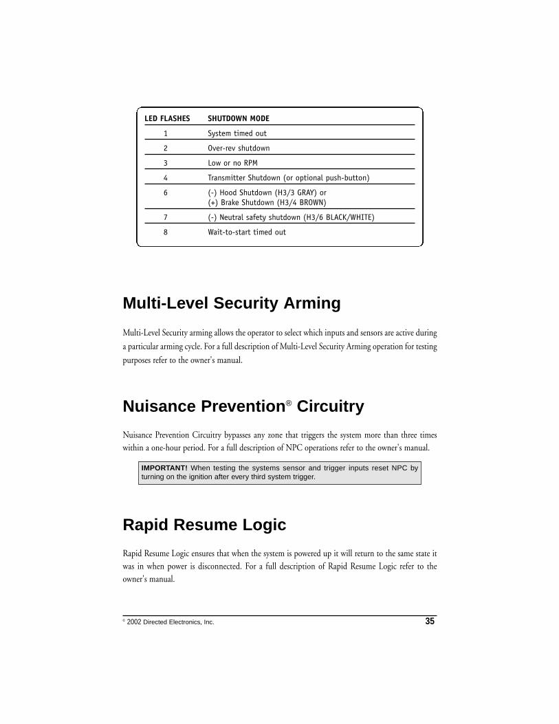
The LED will now report the last system shutdown by flashing for one minute in the below grouped
patterns; the LED will stop flashing when the ignition is turned on.
34 © 2002 Directed Electronics, Inc.
© 2002 Directed Electronics, Inc. 35
Multi-Level Security Arming
Multi-Level Security arming allows the operator to select which inputs and sensors are active during
a particular arming cycle. For a full description of Multi-Level Security Arming operation for testing
purposes refer to the owner's manual.
Nuisance Prevention® Circuitry
Nuisance Prevention Circuitry bypasses any zone that triggers the system more than three timeswithin a one-hour period. For a full description of NPC operations refer to the owner's manual.
Rapid Resume Logic
Rapid Resume Logic ensures that when the system is powered up it will return to the same state itwas in when power is disconnected. For a full description of Rapid Resume Logic refer to theowner's manual.
IMPORTANT! When testing the systems sensor and trigger inputs reset NPC byturning on the ignition after every third system trigger.
LED FLASHES SHUTDOWN MODE
1 System timed out
2 Over-rev shutdown
3 Low or no RPM
4 Transmitter Shutdown (or optional push-button)
6 (-) Hood Shutdown (H3/3 GRAY) or (+) Brake Shutdown (H3/4 BROWN)
7 (-) Neutral safety shutdown (H3/6 BLACK/WHITE)
8 Wait-to-start timed out
36 © 2002 Directed Electronics, Inc.
Timer Mode
Timer Mode allows the operator to program the remote start system to start the engine every threehours a total of 6 times. For a full description of Timer Mode activation refer to the owner's manual.
Diagnostics
The system’s microprocessor monitors and reports all active and violated zones when arming anddisarming. LED flashes indicate the active or violated zone; siren chirps indicate system status.
Arm/Disarm Diagnostics
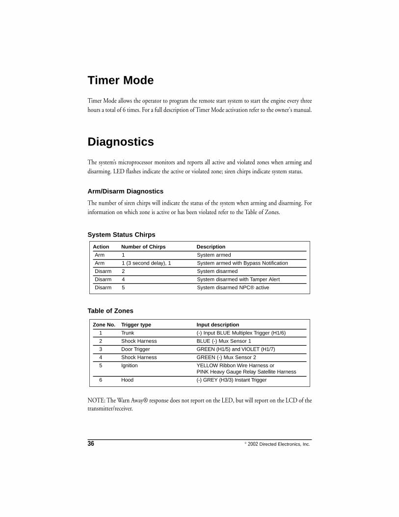
The number of siren chirps will indicate the status of the system when arming and disarming. Forinformation on which zone is active or has been violated refer to the Table of Zones.
System Status Chirps
Table of Zones
NOTE: The Warn Away® response does not report on the LED, but will report on the LCD of thetransmitter/receiver.
Zone No. Trigger type Input description
1 Trunk (-) Input BLUE Multiplex Trigger (H1/6)
2 Shock Harness BLUE (-) Mux Sensor 1
3 Door Trigger GREEN (H1/5) and VIOLET (H1/7)
4 Shock Harness GREEN (-) Mux Sensor 2
5 Ignition YELLOW Ribbon Wire Harness orPINK Heavy Gauge Relay Satellite Harness
6 Hood (-) GREY (H3/3) Instant Trigger
Action Number of Chirps Description
Arm 1 System armed
Arm 1 (3 second delay), 1 System armed with Bypass Notification
Disarm 2 System disarmed
Disarm 4 System disarmed with Tamper Alert
Disarm 5 System disarmed NPC® active
© 2002 Directed Electronics, Inc. 37
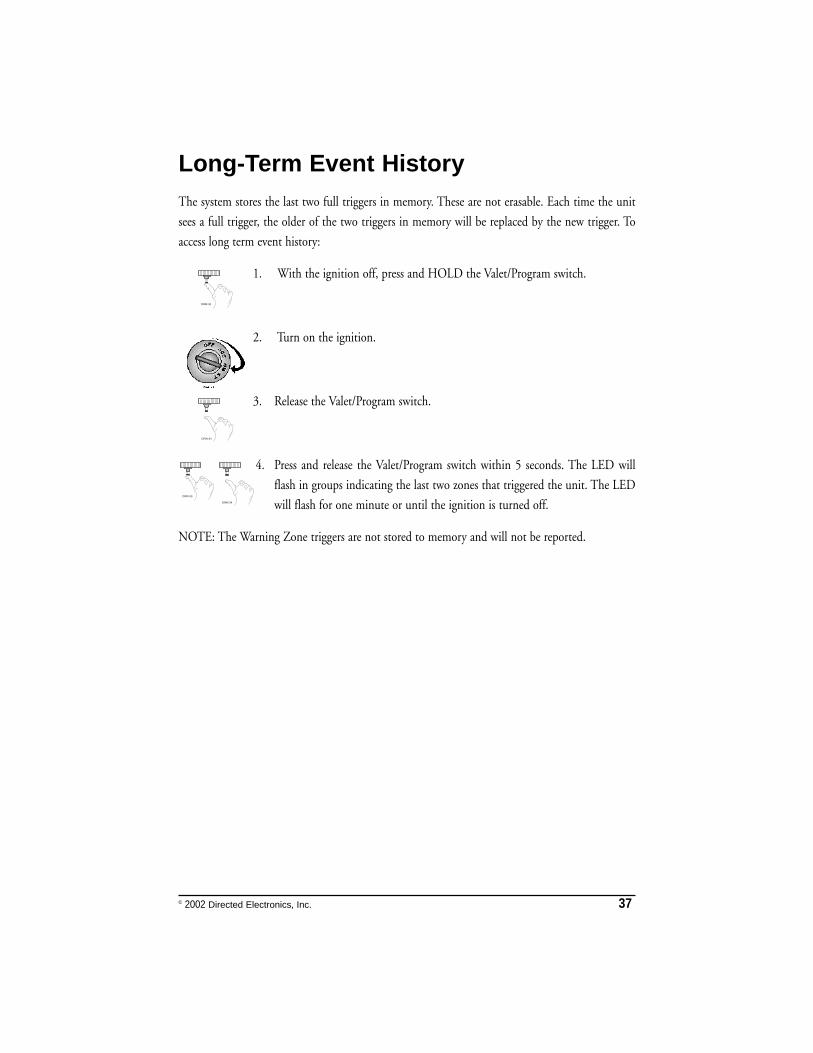
Long-Term Event HistoryThe system stores the last two full triggers in memory. These are not erasable. Each time the unit
sees a full trigger, the older of the two triggers in memory will be replaced by the new trigger. To
access long term event history:
1. With the ignition off, press and HOLD the Valet/Program switch.
2. Turn on the ignition.
3. Release the Valet/Program switch.
4. Press and release the Valet/Program switch within 5 seconds. The LED will
flash in groups indicating the last two zones that triggered the unit. The LED
will flash for one minute or until the ignition is turned off.
NOTE: The Warning Zone triggers are not stored to memory and will not be reported.
38 © 2002 Directed Electronics, Inc.
Safety Check
Before vehicle reassembly, the remote system must be checked to ensure safe and trouble-free
operation. The following test procedure must be used to verify proper installation and operation of
the system. The installation must be completed before testing, including connection to the brake
switch and hood switch.
1. Test the BRAKE shutdown circuit: With the vehicle in Park (P), activate the remote start system.
Once the engine is running, press the brake pedal. The engine should shut down immediately.
If the engine continues to run, check the brake circuit connection.
2. Test the HOOD PIN shutdown circuit: With the vehicle in Park (P), open the hood. Activate
the remote start system. The vehicle should not start. If the starter engages, check your hood pin
and connections.
3. Test the NEUTRAL SAFETY shutdown circuit:
a. Make sure the hood is closed and no other shutdown circuits are active.
b. Set the emergency brake.
c. Turn the ignition key to the run position but do not start the engine.
d. Put the vehicle in Drive (D).
e. Put your foot over the brake pedal but do not press down on it. Be ready to step on the brake
to shutdown the remote start system.
f. Activate the remote start system.
➤ If the starter engages, immediately step on the brake to shut down the system. If it does
engage, recheck the neutral safety input connection. The vehicle may use a mechanical
neutral safety switch. (See H2/6 BLACK/WHITE neutral safety switch input in Remote
Start Harness Wire Connection Guide section of this guide.)
➤ If the starter does not engage, the test is complete.
Once the system passes the three tests, the vehicle can be re-assembled and delivered. Do not use
the remote start system or finalize the installation if it fails any of the safety check tests.
IMPORTANT! Make sure there is adequate clearance to the front and rear of thevehicle before attempting this test.
© 2002 Directed Electronics, Inc. 39
Troubleshooting
Alarm Troubleshooting
Starter kill doesn't work:
➤ Is the correct wire being interrupted? If the car starts when the starter kill relay is completely
disconnected, the wrong starter wire has been cut and interrupted.
➤ Is the yellow wire of the starter kill relay going to primary ignition? This wire must be powered
in the run and start positions.
Shock sensor doesn't trigger the alarm:
➤ Has the NPC™ system been triggered? If so, you will hear 5 chirps when disarming. To check
this, turn the ignition key on and off to clear the NPC™'s memory, and then retest the shock
sensor. For a detailed description of NPC™, see Nuisance Prevention Circuitry section of this
guide.
➤ If the Warn Away® does not work, check the four-pin harness and verify that the end with the
GREEN wire is plugged into the alarm module.
Door input does not immediately trigger full alarm. Instead, chirps are heard for the first 3 seconds:
➤ That's how the progressive two-stage door input works! This is a feature of this system. This is
an instant trigger, remember, since even if the door is instantly closed again, the progression
from chirps to constant siren will continue.
Closing the door triggers the system, but opening the door does not:
➤ Have you correctly identified the type of door switch system? This happens often when the
wrong door input has been used. See the Techsoft DirectFax to identify the polarity of the door
trigger.
System will not passively arm until it is remotely armed and then disarmed:
➤ Are the door inputs connected? Is the H1/6 blue wire connected to the door trigger wire in the
vehicle? Either the H1/5 green or the H1/7 violet should be used instead. (See wiring diagrams.)
Door input does not respond with the progressive trigger, but with immediate full alarm:
➤ Does the Status LED indicate that the trigger was caused by the shock sensor? (See Diagnostics
section of this guide.) The shock sensor, if set to extreme sensitivity, may be detecting the door
unlatching before the door switch sends its signal. Reducing the sensitivity can solve this
problem.
40 © 2002 Directed Electronics, Inc.
The Valet®/Program switch doesn't work.
➤ Is it plugged into the correct socket? See Plug-In LED and Valet®/Program Switch section of
this guide.
Status LED doesn't work.
➤ You've probably guessed already, but here goes: Is it plugged in? (See Plug-In LED and
Valet®/Program Switch section of this guide.) Is the LED plugged into the correct socket?
Door locks operate backwards.
➤ This unit has easily-reversed lock/unlock outputs. Recheck wire connections to see if you have
reversed these.
Remote Start Troubleshooting
The remote start will not activate.
➤ Check the harnesses and their connections. Make sure that the harnesses are completely plugged
into the remote start module. Make sure there are good connections to the vehicle wiring.
➤ Check voltage and fuses. Use a meter to check for voltage between the red wire in the 5-pin
ribbon harness and the black ground wire. If you have less than battery voltage, check the 3A
and both 30A fuses on the relay satellite. Also make sure that the ground wire connects to a good
chassis ground point.
➤ Check diagnostics. The diagnostics will tell you which shutdown is active or not connected.
➤ Check the neutral safety wire; it should be grounded or the remote start will not activate.
The remote start will activate, but the starter never engages.
➤ Check for voltage on the purple starter wire two seconds after the remote start becomes active.
If there is voltage present, skip to Step 4. If there is not voltage present, advance to Step 2.
➤ Check the 30A fuses.
➤ Check diagnostics. If the gray/black wire is detecting ground upon activation, the starter will
not crank.
➤ Make sure the purple starter wire is connected on the starter side of the starter kill/anti-grind
relay.
➤ Does the vehicle have an immobilizer? Some immobilizer systems will not allow the vehicle to
crank if active.
➤ Check connections. The two red heavy gauge input wires on the relay satellite should have solid
connections. "T-taps" or "scotch locks" are not recommended for any high current heavy gauge
wiring. Also, if the vehicle has more than one 12-volt input wire, then connect one red wire to
each.
© 2002 Directed Electronics, Inc. 41
The vehicle starts, but immediately dies.
➤ Does the vehicle have an immobilizer? The vehicle’s immobilizer will cut the fuel and/or spark
during unauthorized starting attempts.
➤ Is the remote start programmed for voltage sense? If so, the start time may not be set high
enough, or you may have to adjust the voltage threshold in programming. Voltage sense will not
work on some vehicles.
➤ Check diagnostics. Sometimes a shutdown will become active during cranking or just after
cranking.
The vehicle starts, but the starter keeps running.
➤ Is the system programmed for engine checking off or voltage sense? When programmed for
either of these features, the engine cranks for the preprogrammed crank time regardless of how
long it takes for the vehicle to actually start. Adjust to a lower cranking time.
➤ Was the Tach Learn successful? The LED must light solid and bright to indicate a successful
learn.
➤ Make sure that there is a tach signal at the purple/white tach input wire of the remote start. If
there is not a tach signal, recheck the connection to the vehicle’s tach wire and make sure the
wire is not broken or shorted to ground leading to the remote start.
The vehicle will start, but will only run for 10 seconds.
➤ Is the remote start programmed for voltage sense? Try programming the unit for low voltage
reference. If this does not work, a tach wire should be used.
➤ Check diagnostics.
The climate control system does not work while the unit is operating the vehicle.
➤ Either the wrong accessory wire is being energized or more than one ignition or accessory wire
must be energized in order to operate the climate control system.

42 © 2002 Directed Electronics, Inc.
© 2002 Directed Electronics, Inc. 43
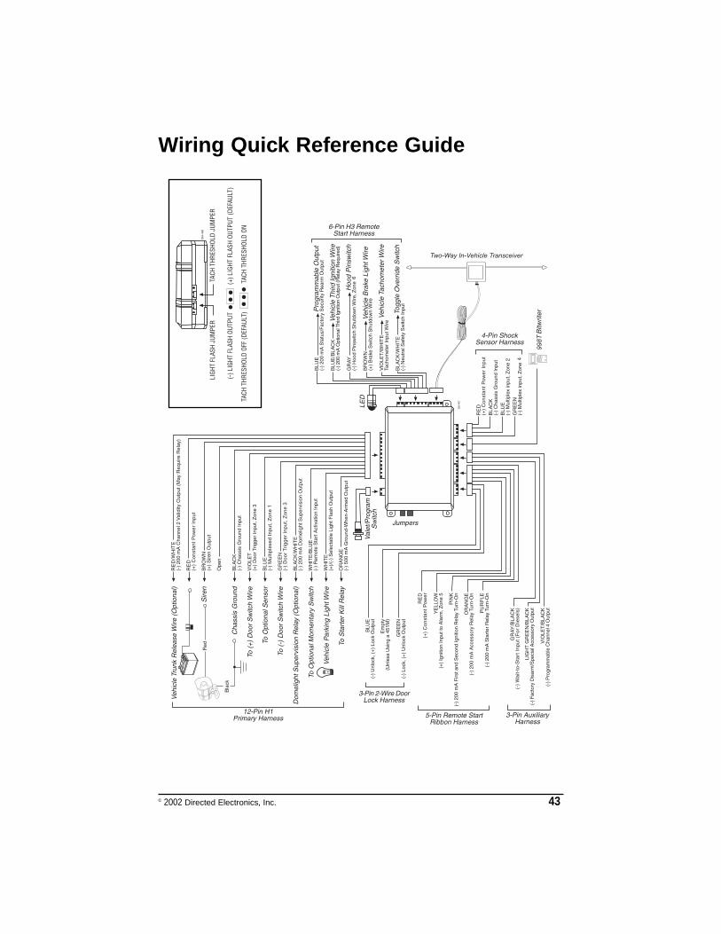
Wiring Quick Reference Guide

44 © 2002 Directed Electronics, Inc.