Embed Size (px)
Citation preview
SIMATIC Industrial PC SIMATIC Microbox PC 427B ______________Operating Instructions (compact) 1
SIMATIC
Industrial PC SIMATIC Microbox PC 427B
Operating Instructions (Compact)
11/2008 A5E00913640-03
Legal information Legal information Warning notice system
This manual contains notices you have to observe in order to ensure your personal safety, as well as to prevent damage to property. The notices referring to your personal safety are highlighted in the manual by a safety alert symbol, notices referring only to property damage have no safety alert symbol. These notices shown below are graded according to the degree of danger.
DANGER indicates that death or severe personal injury will result if proper precautions are not taken.
WARNING indicates that death or severe personal injury may result if proper precautions are not taken.
CAUTION with a safety alert symbol, indicates that minor personal injury can result if proper precautions are not taken.
CAUTION without a safety alert symbol, indicates that property damage can result if proper precautions are not taken.
NOTICE indicates that an unintended result or situation can occur if the corresponding information is not taken into account.
If more than one degree of danger is present, the warning notice representing the highest degree of danger will be used. A notice warning of injury to persons with a safety alert symbol may also include a warning relating to property damage.
Qualified Personnel The device/system may only be set up and used in conjunction with this documentation. Commissioning and operation of a device/system may only be performed by qualified personnel. Within the context of the safety notes in this documentation qualified persons are defined as persons who are authorized to commission, ground and label devices, systems and circuits in accordance with established safety practices and standards.
Proper use of Siemens products Note the following:
WARNING Siemens products may only be used for the applications described in the catalog and in the relevant technical documentation. If products and components from other manufacturers are used, these must be recommended or approved by Siemens. Proper transport, storage, installation, assembly, commissioning, operation and maintenance are required to ensure that the products operate safely and without any problems. The permissible ambient conditions must be adhered to. The information in the relevant documentation must be observed.
Trademarks All names identified by ® are registered trademarks of the Siemens AG. The remaining trademarks in this publication may be trademarks whose use by third parties for their own purposes could violate the rights of the owner.
Disclaimer of Liability We have reviewed the contents of this publication to ensure consistency with the hardware and software described. Since variance cannot be precluded entirely, we cannot guarantee full consistency. However, the information in this publication is reviewed regularly and any necessary corrections are included in subsequent editions.
Siemens AG Industry Sector Postfach 48 48 90026 NÜRNBERG GERMANY
A5E00913640-03 Ⓟ 11/2008
Copyright © Siemens AG 2007, 2008. Technical data subject to change
이 기기는 업무용(A급) 전자파 적합기기로서 판매자 또는 사용자는 이 점을 주의하시기 바라며 가정 외의 지역에서 사용하는 것을 목적으로 합니다.

SIMATIC Microbox PC 427B Operating Instructions (Compact), 11/2008, A5E00913640-03 3
Table of contents
1 Operating Instructions (compact)............................................................................................................... 5
1.1 Components of the Product ...........................................................................................................5 1.2 Device identification data ...............................................................................................................5 1.3 Configuration..................................................................................................................................6 1.4 Safety Instructions .........................................................................................................................7 1.5 Permitted mounting positions.........................................................................................................8 1.6 Installation / panel-mounting..........................................................................................................9 1.7 Connection components ..............................................................................................................11 1.8 Connecting the 24 V DC power supply........................................................................................13 1.9 Protective ground connection ......................................................................................................14 1.10 Commissioning Information .........................................................................................................14 1.11 Service and support .....................................................................................................................15 1.12 Product documentation ................................................................................................................16

Table of contents
SIMATIC Microbox PC 427B 4 Operating Instructions (Compact), 11/2008, A5E00913640-03
SIMATIC Microbox PC 427B Operating Instructions (Compact), 11/2008, A5E00913640-03 5
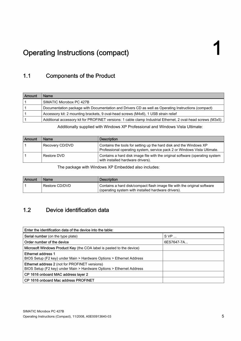
Operating Instructions (compact) 11.1 Components of the Product Amount Name 1 SIMATIC Microbox PC 427B 1 Documentation package with Documentation and Drivers CD as well as Operating Instructions (compact) 1 Accessory kit: 2 mounting brackets, 9 oval-head screws (M4x6), 1 USB strain relief 1 Additional accessory kit for PROFINET versions: 1 cable clamp Industrial Ethernet, 2 oval-head screws (M3x5)
Additionally supplied with Windows XP Professional and Windows Vista Ultimate: Amount Name Description 1 Recovery CD/DVD Contains the tools for setting up the hard disk and the Windows XP
Professional operating system, service pack 2 or Windows Vista Ultimate. 1 Restore DVD Contains a hard disk image file with the original software (operating system
with installed hardware drivers).
The package with Windows XP Embedded also includes: Amount Name Description 1 Restore CD/DVD Contains a hard disk/compact flash image file with the original software
(operating system with installed hardware drivers).
1.2 Device identification data Enter the identification data of the device into the table: Serial number (on the type plate) S VP ... Order number of the device 6ES7647-7A... Microsoft Windows Product Key (the COA label is pasted to the device) Ethernet address 1 BIOS Setup (F2 key) under Main > Hardware Options > Ethernet Address
Ethernet address 2 (not for PROFINET versions) BIOS Setup (F2 key) under Main > Hardware Options > Ethernet Address
CP 1616 onboard MAC address layer 2 CP 1616 onboard Mac address PROFINET
Operating Instructions (compact) 1.3 Configuration
SIMATIC Microbox PC 427B 6 Operating Instructions (Compact), 11/2008, A5E00913640-03
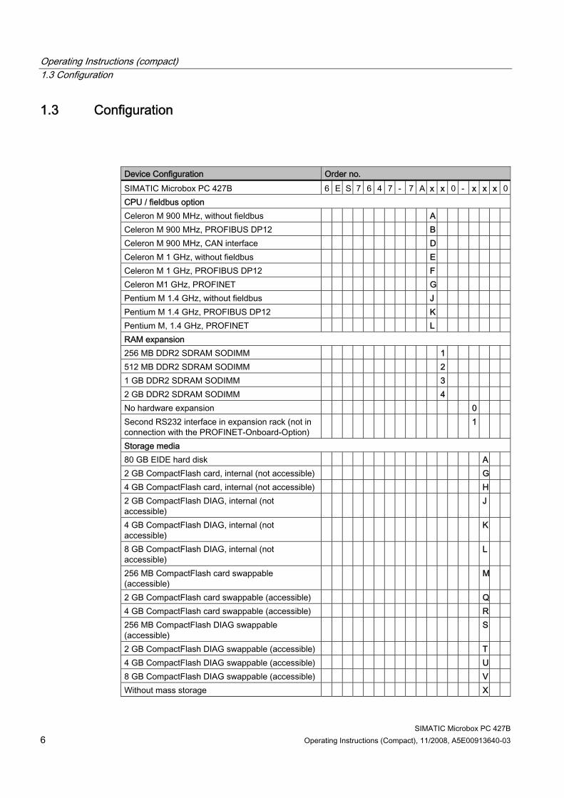
1.3 Configuration
Device Configuration Order no. SIMATIC Microbox PC 427B 6 E S 7 6 4 7 - 7 A x x 0 - x x x 0CPU / fieldbus option Celeron M 900 MHz, without fieldbus A Celeron M 900 MHz, PROFIBUS DP12 B Celeron M 900 MHz, CAN interface D Celeron M 1 GHz, without fieldbus E Celeron M 1 GHz, PROFIBUS DP12 F Celeron M1 GHz, PROFINET G Pentium M 1.4 GHz, without fieldbus J Pentium M 1.4 GHz, PROFIBUS DP12 K Pentium M, 1.4 GHz, PROFINET L RAM expansion 256 MB DDR2 SDRAM SODIMM 1 512 MB DDR2 SDRAM SODIMM 2 1 GB DDR2 SDRAM SODIMM 3 2 GB DDR2 SDRAM SODIMM 4 No hardware expansion 0 Second RS232 interface in expansion rack (not in connection with the PROFINET-Onboard-Option)
1
Storage media 80 GB EIDE hard disk A 2 GB CompactFlash card, internal (not accessible) G 4 GB CompactFlash card, internal (not accessible) H 2 GB CompactFlash DIAG, internal (not accessible)
J
4 GB CompactFlash DIAG, internal (not accessible)
K
8 GB CompactFlash DIAG, internal (not accessible)
L
256 MB CompactFlash card swappable (accessible)
M
2 GB CompactFlash card swappable (accessible) Q 4 GB CompactFlash card swappable (accessible) R 256 MB CompactFlash DIAG swappable (accessible)
S
2 GB CompactFlash DIAG swappable (accessible) T 4 GB CompactFlash DIAG swappable (accessible) U 8 GB CompactFlash DIAG swappable (accessible) V Without mass storage X
Operating Instructions (compact) 1.4 Safety Instructions
SIMATIC Microbox PC 427B Operating Instructions (Compact), 11/2008, A5E00913640-03 7
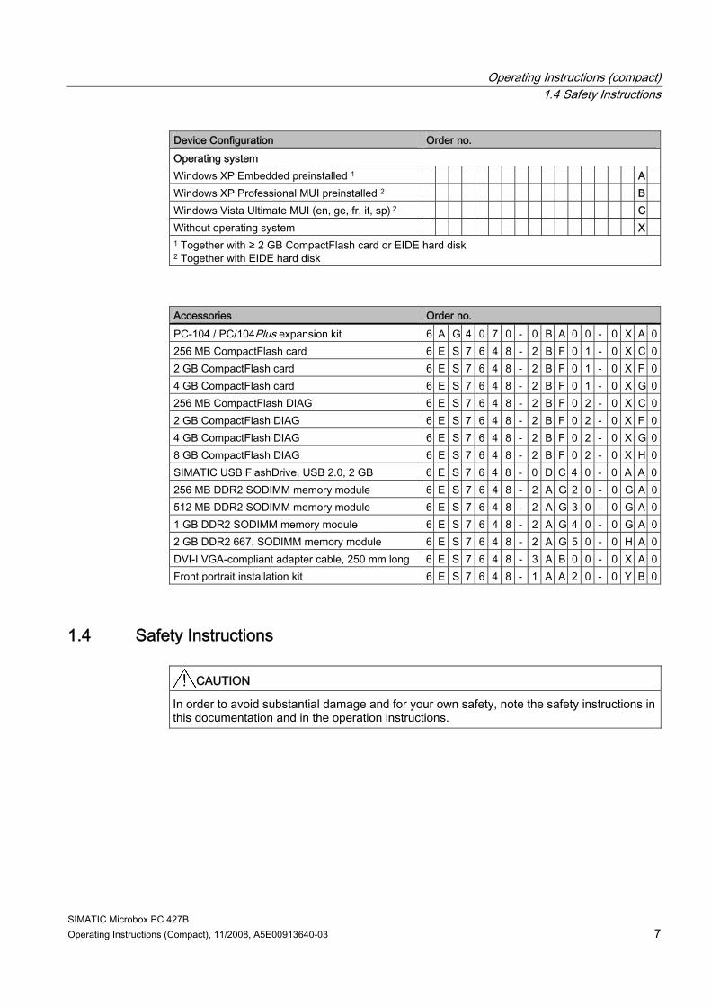
Device Configuration Order no. Operating system Windows XP Embedded preinstalled 1 A Windows XP Professional MUI preinstalled 2 B Windows Vista Ultimate MUI (en, ge, fr, it, sp) 2 C Without operating system X 1 Together with ≥ 2 GB CompactFlash card or EIDE hard disk 2 Together with EIDE hard disk
Accessories Order no. PC-104 / PC/104Plus expansion kit 6 A G 4 0 7 0 - 0 B A 0 0 - 0 X A 0256 MB CompactFlash card 6 E S 7 6 4 8 - 2 B F 0 1 - 0 X C 02 GB CompactFlash card 6 E S 7 6 4 8 - 2 B F 0 1 - 0 X F 04 GB CompactFlash card 6 E S 7 6 4 8 - 2 B F 0 1 - 0 X G 0256 MB CompactFlash DIAG 6 E S 7 6 4 8 - 2 B F 0 2 - 0 X C 02 GB CompactFlash DIAG 6 E S 7 6 4 8 - 2 B F 0 2 - 0 X F 04 GB CompactFlash DIAG 6 E S 7 6 4 8 - 2 B F 0 2 - 0 X G 08 GB CompactFlash DIAG 6 E S 7 6 4 8 - 2 B F 0 2 - 0 X H 0SIMATIC USB FlashDrive, USB 2.0, 2 GB 6 E S 7 6 4 8 - 0 D C 4 0 - 0 A A 0256 MB DDR2 SODIMM memory module 6 E S 7 6 4 8 - 2 A G 2 0 - 0 G A 0512 MB DDR2 SODIMM memory module 6 E S 7 6 4 8 - 2 A G 3 0 - 0 G A 01 GB DDR2 SODIMM memory module 6 E S 7 6 4 8 - 2 A G 4 0 - 0 G A 02 GB DDR2 667, SODIMM memory module 6 E S 7 6 4 8 - 2 A G 5 0 - 0 H A 0DVI-I VGA-compliant adapter cable, 250 mm long 6 E S 7 6 4 8 - 3 A B 0 0 - 0 X A 0Front portrait installation kit 6 E S 7 6 4 8 - 1 A A 2 0 - 0 Y B 0
1.4 Safety Instructions
CAUTION In order to avoid substantial damage and for your own safety, note the safety instructions in this documentation and in the operation instructions.
Operating Instructions (compact) 1.5 Permitted mounting positions
SIMATIC Microbox PC 427B 8 Operating Instructions (Compact), 11/2008, A5E00913640-03
1.5 Permitted mounting positions
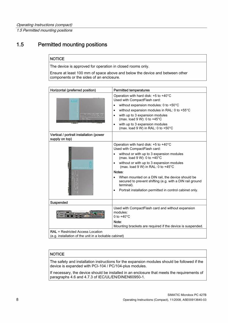
NOTICE The device is approved for operation in closed rooms only. Ensure at least 100 mm of space above and below the device and between other components or the sides of an enclosure.
Horizontal (preferred position) Permitted temperatures
Operation with hard disk: +5 to +40°C Used with CompactFlash card: • without expansion modules: 0 to +50°C • without expansion modules in RAL: 0 to +55°C • with up to 3 expansion modules
(max. load 9 W): 0 to +45°C • with up to 3 expansion modules
(max. load 9 W) in RAL: 0 to +50°C
Vertical / portrait installation (power supply on top)
Operation with hard disk: +5 to +40°C Used with CompactFlash card: • without or with up to 3 expansion modules
(max. load 9 W): 0 to +40°C • without or with up to 3 expansion modules
(max. load 9 W) in RAL: 0 to +45°C Notes: • When mounted on a DIN rail, the device should be
secured to prevent shifting (e.g. with a DIN rail ground terminal).
• Portrait installation permitted in control cabinet only.
Suspended
Used with CompactFlash card and without expansion modules: 0 to +40°C Note: Mounting brackets are required if the device is suspended.
RAL = Restricted Access Location (e.g. installation of the unit in a lockable cabinet)
NOTICE The safety and installation instructions for the expansion modules should be followed if the device is expanded with PCI-104 / PC/104-plus modules. If necessary, the device should be installed in an enclosure that meets the requirements of paragraphs 4.6 and 4.7.3 of IEC/UL/EN/DINEN60950-1.
Operating Instructions (compact) 1.6 Installation / panel-mounting
SIMATIC Microbox PC 427B Operating Instructions (Compact), 11/2008, A5E00913640-03 9
1.6 Installation / panel-mounting
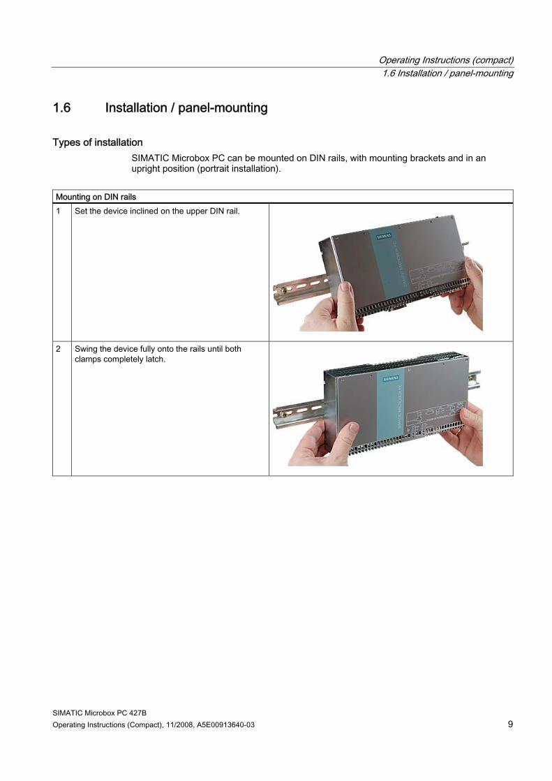
Types of installation SIMATIC Microbox PC can be mounted on DIN rails, with mounting brackets and in an upright position (portrait installation).
Mounting on DIN rails 1 Set the device inclined on the upper DIN rail.
2 Swing the device fully onto the rails until both clamps completely latch.
Operating Instructions (compact) 1.6 Installation / panel-mounting
SIMATIC Microbox PC 427B 10 Operating Instructions (Compact), 11/2008, A5E00913640-03
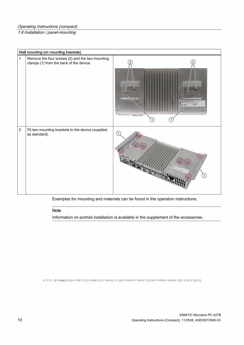
Wall mounting (on mounting brackets) 1 Remove the four screws (2) and the two mounting
clamps (1) from the back of the device.
2 Fit two mounting brackets to the device (supplied as standard).
Examples for mounting and materials can be found in the operation instructions.
Note Information on portrait installation is available in the supplement of the accessories.
이 기기는 업무용(A급) 전자파 적합기기로서 판매자 또는 사용자는 이 점을 주의하시기 바라며 가정 외의 지역에서 사용하는 것을 목적으로 합니다.
Operating Instructions (compact) 1.7 Connection components
SIMATIC Microbox PC 427B Operating Instructions (Compact), 11/2008, A5E00913640-03 11
1.7 Connection components
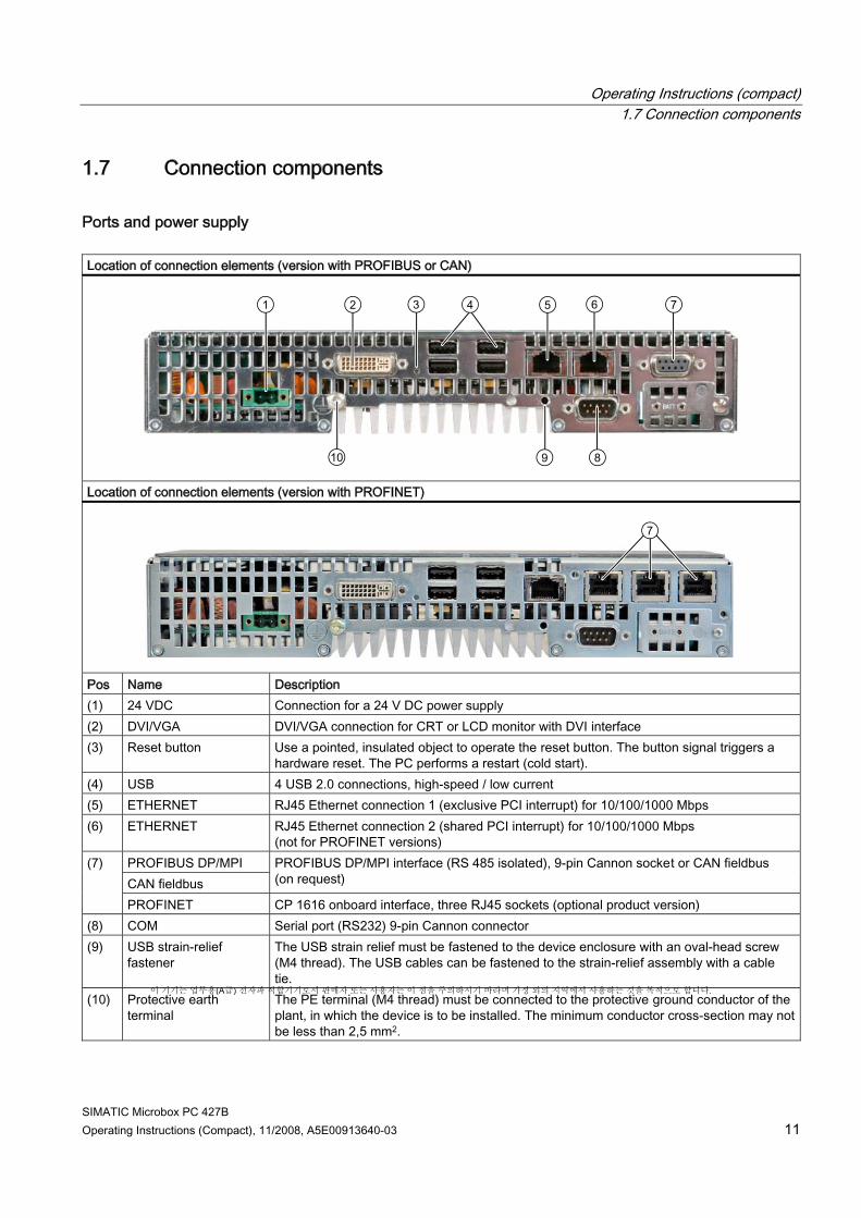
Ports and power supply Location of connection elements (version with PROFIBUS or CAN)
Location of connection elements (version with PROFINET)
Pos Name Description (1) 24 VDC Connection for a 24 V DC power supply (2) DVI/VGA DVI/VGA connection for CRT or LCD monitor with DVI interface (3) Reset button Use a pointed, insulated object to operate the reset button. The button signal triggers a
hardware reset. The PC performs a restart (cold start). (4) USB 4 USB 2.0 connections, high-speed / low current (5) ETHERNET RJ45 Ethernet connection 1 (exclusive PCI interrupt) for 10/100/1000 Mbps (6) ETHERNET RJ45 Ethernet connection 2 (shared PCI interrupt) for 10/100/1000 Mbps
(not for PROFINET versions) PROFIBUS DP/MPI CAN fieldbus
PROFIBUS DP/MPI interface (RS 485 isolated), 9-pin Cannon socket or CAN fieldbus (on request)
(7)
PROFINET CP 1616 onboard interface, three RJ45 sockets (optional product version) (8) COM Serial port (RS232) 9-pin Cannon connector (9) USB strain-relief
fastener The USB strain relief must be fastened to the device enclosure with an oval-head screw (M4 thread). The USB cables can be fastened to the strain-relief assembly with a cable tie.
(10) Protective earth terminal
The PE terminal (M4 thread) must be connected to the protective ground conductor of the plant, in which the device is to be installed. The minimum conductor cross-section may not be less than 2,5 mm2.
이 기기는 업무용(A급) 전자파 적합기기로서 판매자 또는 사용자는 이 점을 주의하시기 바라며 가정 외의 지역에서 사용하는 것을 목적으로 합니다.
Operating Instructions (compact) 1.7 Connection components
SIMATIC Microbox PC 427B 12 Operating Instructions (Compact), 11/2008, A5E00913640-03
CAUTION Data may be lost when the PC performs a hardware reset.
Operating Instructions (compact) 1.8 Connecting the 24 V DC power supply
SIMATIC Microbox PC 427B Operating Instructions (Compact), 11/2008, A5E00913640-03 13
1.8 Connecting the 24 V DC power supply
To be noted before you connect the device Note the following in order to operate the device safely and according to regulation:
WARNING The device should only be connected to a 24V DC power supply which satisfies the requirements of safe extra low voltage (SELV). If the device is used on a wall, in an open rack or other similar locations, an NEC Class 2 current source is required in order to meet the UL requirements (UL 60950-1). In all other cases (IEC / EN / DIN EN 609501) either a current source of limited output (LPS = Low Power Source), or a line-side fuse or a line-side circuit breaker is necessary. The power needs to be limited to a value below 4.16 A. The fuse value required: Max. 4 A. If the device is used in fire-proof enclosures to IEC/UL/EN/DIN/EN 60950-1, there are no requirements to limit the current of the supply voltage. Use the special plug supplied to connect the supply voltage. Connect the PE conductors as described in the next section.
NOTICE The permitted cable cross-section for the 24 VDC connection is 0.75 mm2 to 2.5 mm2.
NOTICE If a CompactFlash card is used in the device, make sure that the card is seated correctly before you connect it.
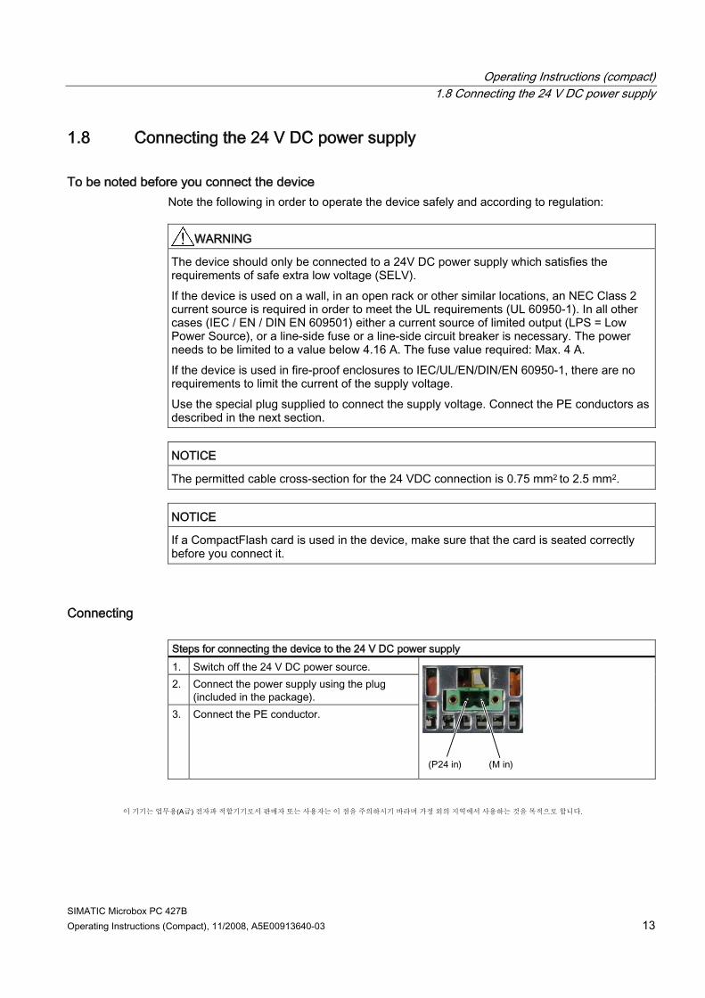
Connecting Steps for connecting the device to the 24 V DC power supply 1. Switch off the 24 V DC power source. 2. Connect the power supply using the plug
(included in the package). 3. Connect the PE conductor.
이 기기는 업무용(A급) 전자파 적합기기로서 판매자 또는 사용자는 이 점을 주의하시기 바라며 가정 외의 지역에서 사용하는 것을 목적으로 합니다.
Operating Instructions (compact) 1.9 Protective ground connection
SIMATIC Microbox PC 427B 14 Operating Instructions (Compact), 11/2008, A5E00913640-03
1.9 Protective ground connection
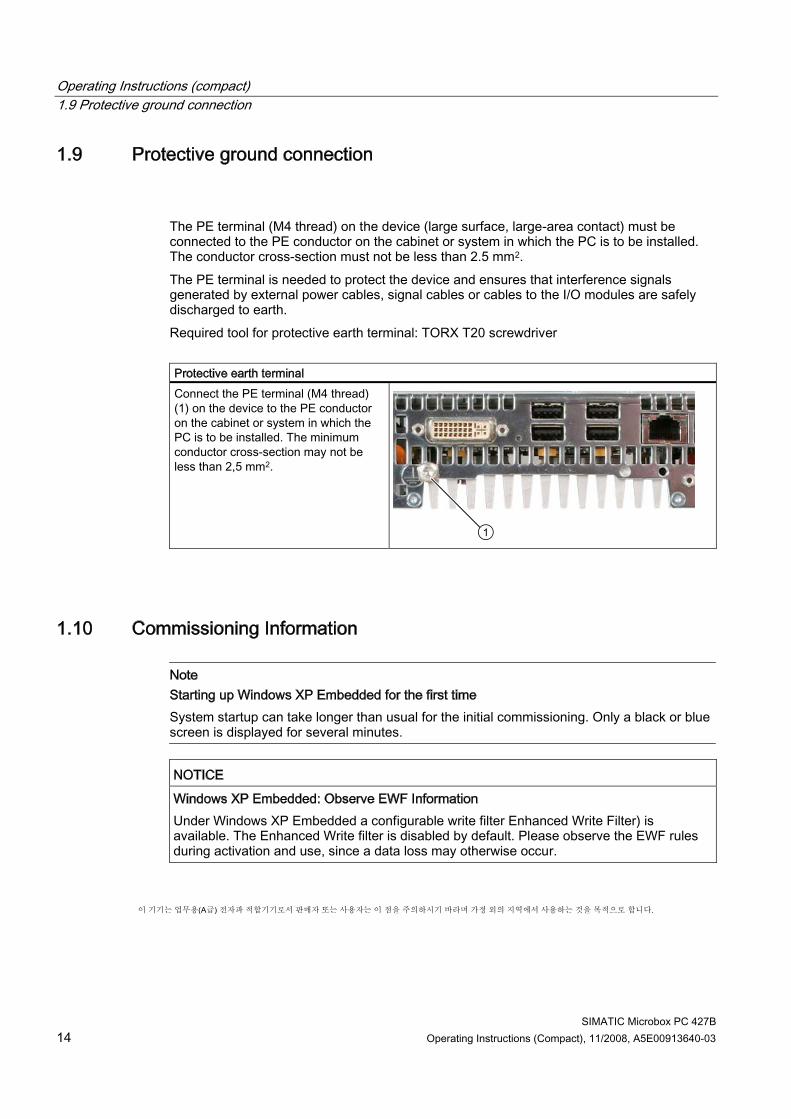
The PE terminal (M4 thread) on the device (large surface, large-area contact) must be connected to the PE conductor on the cabinet or system in which the PC is to be installed. The conductor cross-section must not be less than 2.5 mm2. The PE terminal is needed to protect the device and ensures that interference signals generated by external power cables, signal cables or cables to the I/O modules are safely discharged to earth. Required tool for protective earth terminal: TORX T20 screwdriver Protective earth terminal Connect the PE terminal (M4 thread) (1) on the device to the PE conductor on the cabinet or system in which the PC is to be installed. The minimum conductor cross-section may not be less than 2,5 mm2.
1.10 Commissioning Information
Note Starting up Windows XP Embedded for the first time System startup can take longer than usual for the initial commissioning. Only a black or blue screen is displayed for several minutes.
NOTICE Windows XP Embedded: Observe EWF Information Under Windows XP Embedded a configurable write filter Enhanced Write Filter) is available. The Enhanced Write filter is disabled by default. Please observe the EWF rules during activation and use, since a data loss may otherwise occur.
이 기기는 업무용(A급) 전자파 적합기기로서 판매자 또는 사용자는 이 점을 주의하시기 바라며 가정 외의 지역에서 사용하는 것을 목적으로 합니다.
Operating Instructions (compact) 1.11 Service and support
SIMATIC Microbox PC 427B Operating Instructions (Compact), 11/2008, A5E00913640-03 15
1.11 Service and support
Local information Contain your Siemens representative (http://www.siemens.com/automation/partner) if you have questions about the products described here.
Technical documentation for SIMATIC products You can find additional documentation for SIMATIC products and systems in the Internet: SIMATIC Guide manuals (http://www.automation.siemens.com/simatic/portal/html_76/support_techdoku.htm)
Easy shopping at the mall You can find the online catalog and order system under: Industrial Automation and Drive Technologies (http://mall.automation.siemens.com)
Training center All the training options are listed at: SITRAIN homepage (http://www.sitrain.com) Find a contact at: Tel. + 49 911 895 3200
Technical support You can contact technical support for all Industry Automation and Drive Technologies products by: ● Phone: +49 180 5050 222 ● Fax: +49 180 5050 223 ● Internet: Online support request form: (http://www.siemens.com/automation/support-
request) When you contact the customer support, please have the following information for the technician on hand: ● BIOS version ● Order No. (MLFB) of the device ● Installed additional software ● Installed additional hardware
Online Service & Support Information about the product, Support and Service, right through to the Technical Forum, can be found at: Industry Automation and Drive Technologies - Homepage (http://www.siemens.com/automation/service&support)
After-sales information system for SIMATIC PC / PG Information about contacts, drivers, and BIOS updates, FAQs and Customer Support can be found at: After-sales information system for SIMATIC PC / PG (http://www.automation.siemens.com/Industrial-PC/html_76/support/asis.htm)
Operating Instructions (compact) 1.12 Product documentation
SIMATIC Microbox PC 427B 16 Operating Instructions (Compact), 11/2008, A5E00913640-03
1.12 Product documentation
Product documentation Detailed operating instructions for the Microbox PC 427B can be downloaded as a PDF file from the Internet at the following address: SIMATIC Guide manuals (http://www.automation.siemens.com/simatic/portal/html_76/support_techdoku.htm)