Embed Size (px)
Citation preview

OPERATING INSTRUCTIONS
ekey net Version 4.2.0 and above
ID 99/235/0/93 V5
Created on: 14.11.2013
Printed on: 14.11.2013 ekey net User Guide
© 2012 – ekey biometric systems GmbH Page 2 of 222
Document Properties
VERSION 4
CONFIDENTIALITY PUBLIC
STATUS Released
AUTHOR Thomas Reiter
REVISION
MAILING LIST
FILING
Document History
VERSION DATE PERSON IN
CHARGE
MODIFICATIONS
1.0 24.03.2010 picg First version
1.1 16.04.2010 picg Corrections and Additions
1.2 20.04.2010 picg Modification of Product names
ekey net “private” -> “light”
ekey net “print” -> “com”
1.3 11.01.2010 reit Modification of screenshots and text
new features V 4.0.6
Corrections and Additions
1.4 25.05.2011 reit Version 4.1 added
1.5 05.9.2011 reit Added FAQ CV LAN
1.6 23.11.201 reit LICENSE MODELS updated
1.7 22.12.2011 reit SQL Table Type changed
1.8 09.01.2012 reit New UDP protocol
1.9 02.02.2012 reit Wiegand diagram
2.0 08.03.2012 reit New UDP protocol
2,1 04.04.2012 reit Wiegand diagram changed
2.2 14.05.2012 reit UDP protocol correction
3 02.11.2012 Reit ekey net 4.1.8 changes: Chapter 6.6.7.2.2 Holiday Allocation Available 1-5
ID 99/235/0/93 V5
Created on: 14.11.2013
Printed on: 14.11.2013 ekey net User Guide
© 2012 – ekey biometric systems GmbH Page 3 of 222
removed
Chapter 8.1.1.5 SPECIAL MODES FOR TIME ZONE
removed
Chapter 17 ekey net Alarm Plans are not longer
available since version 4.2
Location Map removed
No individual pictures (Users/Terminals)
New Featurelist
4 10.1.2013 Reit Text changes composite panels
5 14.11.2013 Reit ekey net 4.2 infos
Entitlement to Modifications
NAME COMPANY PHONE EMAIL
REIT ekey biometric
systems GmbH

ID 99/235/0/93 V5
Created on: 14.11.2013
Printed on: 14.11.2013 ekey net User Guide
© 2012 – ekey biometric systems GmbH Page 4 of 222
Changes with ekey net version 4.2
Updating to ekey net version 4.2 brings several changes. Depending on software status and
operation mode, some items or screenshots in the operating instructions may not be available or may appear slightly different.
Operation mode:
ekey net 4.2 can be operated in 2 different modes. A new mode has been created especially
for our new finger scanners, in order to guarantee an even better recognition performance.
Operation mode
(to be set in Options)
Classic Advanced
Combined systems with Atmel and Authenthec sensors
are still supported.
After a system update, the software starts automatically in
the Classic mode.
Solely ekey net finger scanners with Authenthec
sensors
can be used.
After a new installation, the software starts
automatically in the Advanced mode.
Update from ekey net 4.x to 4.2
After an update the software starts in the Classic mode, because an installation has been identified.
If you use only ekey net finger scanners with Authenthec sensors,
you can now switch to „Advanced“ under Options.
This allows a better recognition performance, a new learning finger concept, etc.
Please note:
- All the users must be enrolled anew afterwards - All the Atmel finger scanners will be deleted
- Server matching will be disabled - The finger scanner firmware must be updated via ModulUpdate

ID 99/235/0/93 V5
Created on: 14.11.2013
Printed on: 14.11.2013 ekey net User Guide
© 2012 – ekey biometric systems GmbH Page 5 of 222
Table of Contents
1 INTRODUCTION ...................................................................................... 11 1.1 PURPOSE OF THE USER GUIDE ...................................................................... 11 1.2 DEFINITIONS AND ABBREVIATIONS ................................................................ 11 1.3 SYMBOL DESCRIPTION ............................................................................... 14 1.4 CONNECTION WITH OTHER DOCUMENTS .......................................................... 14
2 SYSTEM DESIGN ..................................................................................... 15 2.1 SYSTEM ARCHITECTURE ............................................................................. 15 2.2 SYSTEM INPUT ........................................................................................ 16
2.2.1 ekey net admin ............................................................................. 16 2.2.2 ekey net FS .................................................................................. 17 2.2.3 ekey bit and ekey net desktop RFID reader ....................................... 17 2.2.4 ekey net CP .................................................................................. 17
3 LICENSING ............................................................................................. 18 3.1 LICENSE MODEL ...................................................................................... 18 3.2 UPGRADE .............................................................................................. 18 3.3 DIFFERENCES IN THE LICENSING MODELS ........................................................ 19 3.4 LICENSE KEY .......................................................................................... 20 3.5 LICENSE MANAGER ................................................................................... 21
3.5.1 Adding a License ........................................................................... 22 3.5.2 Activating a License ....................................................................... 22
4 DEVICES ................................................................................................. 28 4.1 DEVICE TYPES ........................................................................................ 28 4.2 FUNCTIONS OF THE DEVICES IN EKEY NET ........................................................ 30
4.2.1 ekey net FS (Finger Scanner) .......................................................... 30 4.2.2 LED Indications on the Finger Scanners:........................................... 31
Description ................................................................................................................... 31 4.2.3 ekey net Control Panel (CP) – ekey net Composite CP ........................ 32 4.2.4 The 7-Segment Control Panel Display .............................................. 33 4.2.5 ekey bit ....................................................................................... 33 4.2.6 ekey net CV (converter) LAN .......................................................... 34 4.2.7 ekey net Terminal Server ............................................................... 34 4.2.8 ekey net Master Server .................................................................. 34 4.2.9 ekey net Restore ........................................................................... 34
5 SOFTWARE INSTALLATION ..................................................................... 36 5.1 INSTALLATION PREPARATION ....................................................................... 36 5.2 CARRYING OUT THE INSTALLATION ................................................................ 37
5.2.1 General Installation Process ............................................................ 37 5.2.2 New Installation of the ekey net Software Components....................... 38 5.2.3 ekey net CV LAN ........................................................................... 46
5.2.3.1 Optical signalling .............................................................................................. 46

ID 99/235/0/93 V5
Created on: 14.11.2013
Printed on: 14.11.2013 ekey net User Guide
© 2012 – ekey biometric systems GmbH Page 6 of 222
5.2.3.2 Configuration ................................................................................................... 47 5.2.3.2.1 Assignment of a New IP Address ..................................................................... 48
5.2.3.2.1.1 IP Assignment via MAC Address ................................................................ 48 5.2.3.2.1.2 IP Assignment of the Listed Devices .......................................................... 49
5.2.3.3 Firmware Update ekey Converter LAN ................................................................. 50 5.2.3.4 Functional check of the ekey Converter LAN Function within the network .................. 51
5.2.3.4.1 PING .......................................................................................................... 51 5.2.3.4.2 Portscan ..................................................................................................... 51 5.2.3.4.3 FAQ ekey net LAN Converter cannot be found ................................................... 52
5.2.4 Module Update ............................................................................. 53 5.2.5 Completion of the Installation ......................................................... 56
5.3 UPDATING FROM PREVIOUS EKEY NET SOFTWARE VERSIONS ................................... 56 5.3.1 General Information ...................................................................... 56 5.3.2 Licenses ...................................................................................... 56 5.3.3 Setup .......................................................................................... 58 5.3.4 Configuration Changes during the Update ......................................... 59
6 CONFIGURATION AND ADMINISTRATION OF THE SYSTEM ..................... 60 6.1 EKEY NET ADMIN START WINDOW .................................................................. 60 6.2 THE “START” MENU ................................................................................. 62 6.3 THE “DATA” MENU .................................................................................. 64
6.3.1 Functions and Contents in the Data Window ...................................... 64 6.3.2 Reports on User activities or Finger Scanner activities ........................ 65
6.3.2.1 Access by Finger Scanner: ................................................................................. 66 6.3.2.2 Access by User ................................................................................................ 66
6.3.3 Data Window in Device Status ........................................................ 67 6.3.4 FAR Check ................................................................................... 67
6.4 THE “USER” MENU .................................................................................. 68 6.4.1 Schematic Procedure for Adding a User ............................................ 69 6.4.2 Entering the Parameter and Data .................................................... 69
6.4.2.1 Companies and User Groups .............................................................................. 69 6.4.2.2 Adding Users and enrolling Fingerprints ............................................................... 71
6.4.3 Editing Users and User Groups ........................................................ 78 6.4.3.1 Modification of Parameters ................................................................................. 78 6.4.3.2 Force Update ................................................................................................... 79
6.4.4 Deleting Users and User Groups ...................................................... 79 6.4.5 User Export and Import ................................................................. 80
6.4.5.1 User Export ..................................................................................................... 80 6.4.5.2 User Import ..................................................................................................... 81
6.5 THE “AUTHORISATIONS” MENU ................................................................ 82 6.5.1 Authorisations .............................................................................. 82
6.5.1.1 Assignment of Authorisations ............................................................................. 82 6.5.1.2 Force Update ................................................................................................... 84 6.5.1.3 Inheritance ..................................................................................................... 84 6.5.1.4 Delete or Change Authorisations ......................................................................... 85
6.6 THE “TERMINALS” MENU ......................................................................... 86 6.6.1 General Configuration .................................................................... 86 6.6.2 Configuration on the Terminal Level ................................................. 88 6.6.3 Setting Terminals Group and Device Parameters ................................ 88
6.6.3.1 Terminal Groups .............................................................................................. 88 6.6.3.1.1 Configuration of a Terminal Group “Management” ............................................. 91 6.6.3.1.2 Configuration of the Terminal Group “ekey net Terminal Server” ......................... 92 6.6.3.1.3 Configuring the Terminal Group “ekey net CV LAN” ........................................... 97
6.6.3.1.3.1 ekey net CV LAN ONLINE in the System ..................................................... 98

ID 99/235/0/93 V5
Created on: 14.11.2013
Printed on: 14.11.2013 ekey net User Guide
© 2012 – ekey biometric systems GmbH Page 7 of 222
6.6.3.1.3.2 ekey net CV LAN is OFFLINE or not yet installed in the System: ..................... 99 6.6.3.2 Setting up the Devices (Terminals) ................................................................... 100
6.6.3.2.1 Adding an ekey net Control Panel ................................................................. 100 6.6.3.2.1.1 Control Panel ONLINE in the System ........................................................ 101 6.6.3.2.1.2 Control Panel OFFLINE or not yet installed in the System: .......................... 101
6.6.3.2.2 ekey net Composite Control Panel Arrangement .............................................. 104 6.6.3.2.3 Adding an ekey net FS ................................................................................ 106
6.6.3.2.3.1 Finger Scanner ONLINE in the System ..................................................... 106 6.6.3.2.3.2 Finger Scanner OFFLINE or not yet installed in the System: ........................ 107
6.6.3.3 Send Changes to Terminals ............................................................................. 114 6.6.4 Editing Terminals and Terminal Groups .......................................... 114
6.6.4.1 Changing Parameters ...................................................................................... 114 6.6.4.2 Moving Terminals and Terminal Groups ............................................................. 114 6.6.4.3 Force Update ................................................................................................. 114
6.6.5 Deleting Terminals and Terminal Groups ........................................ 114 6.6.6 Time zone .................................................................................. 115
6.6.6.1 Creating a New Time zone ............................................................................... 115 6.6.6.1.1 Time from - until ........................................................................................ 117 6.6.6.1.2 Keep-switched function ............................................................................... 117 6.6.6.1.3 Timed controlled operations ......................................................................... 119 6.6.6.1.4 Send Changes to Terminals .......................................................................... 120
6.6.6.2 Duplicating Time zones ................................................................................... 120 6.6.6.3 Editing Time zones (change) ............................................................................ 120 6.6.6.4 Deleting Time zones ....................................................................................... 122
6.6.7 Calendar .................................................................................... 122 6.6.7.1 Creating a New Calendar ................................................................................. 123 6.6.7.2 Creating a Calendar ........................................................................................ 124
6.6.7.2.1 New Calendar Entry .................................................................................... 124 6.6.7.2.2 Parameters ................................................................................................ 124 6.6.7.2.3 Send Changes to Terminals .......................................................................... 125
6.6.7.3 Editing a Calendar .......................................................................................... 125 6.6.7.4 Deleting a Calendar ........................................................................................ 125
6.7 THE “STATUS” MENU ............................................................................. 126 6.7.1 General ..................................................................................... 126 6.7.2 The Status Window ..................................................................... 126 6.7.3 Logging in Device Status .............................................................. 128
6.8 THE “BASIC SETTINGS” MENU ................................................................... 128
7 THE WIZARD ......................................................................................... 129 7.1 COMPANY ............................................................................................ 130 7.2 USER GROUPS ...................................................................................... 130 7.3 CREATE USER ....................................................................................... 131 7.4 ENROL FINGER ...................................................................................... 131 7.5 ADDITIONAL USER DATA .......................................................................... 132 7.6 ASSIGN TERMINAL SERVER ....................................................................... 132 7.7 CREATE CONVERTER ............................................................................... 133 7.8 CREATE TERMINAL.................................................................................. 134
8 BASIC SETTINGS AND SYSTEM ADJUSTMENTS ...................................... 135 8.1 BASIC SETTINGS ................................................................................... 135
8.1.1 OPTIONS ................................................................................... 136 8.1.1.1 OPTIONS ...................................................................................................... 136 8.1.1.2 RFID ............................................................................................................ 138 8.1.1.3 NOTIFICATIONS ............................................................................................. 139 8.1.1.4 CALENDAR .................................................................................................... 141

ID 99/235/0/93 V5
Created on: 14.11.2013
Printed on: 14.11.2013 ekey net User Guide
© 2012 – ekey biometric systems GmbH Page 8 of 222
8.1.2 Actions ...................................................................................... 142 8.1.2.1 Creating Custom Made Actions ......................................................................... 144 8.1.2.2 Deleting Actions ............................................................................................. 147 8.1.2.3 Resetting Actions ........................................................................................... 147
8.1.3 Events ....................................................................................... 148 8.1.3.1 Creating User Defined Events ........................................................................... 150 8.1.3.2 Deleting Events .............................................................................................. 152 8.1.3.3 Resetting Events ............................................................................................ 152
8.1.4 Devices (Device Types) ................................................................ 152 8.1.4.1 Creating User Defined Devices ......................................................................... 153
8.1.4.1.1 General ..................................................................................................... 154 8.1.4.1.2 Creating a New Device Type ......................................................................... 154 8.1.4.1.3 Settings for New Types of ekey net FS ........................................................... 155
8.1.4.1.3.1 Properties of the Devices ....................................................................... 155 8.1.4.1.3.2 RFID – The following settings apply only for ekey net FS RFID ..................... 155 8.1.4.1.3.3 Event Allocation ................................................................................... 156
8.1.4.1.3.3.1 The following settings apply only for Feller net M(S,L) FS ...................... 157 8.1.4.1.3.3.2 The following settings apply only for Feller net M(S,L) FS REL ................ 157
8.1.4.1.3.4 Event Conversion.................................................................................. 158 8.1.4.1.4 Settings for the New Type ekey net 3 CP WM ................................................. 159
8.1.4.1.4.1 Device Switches ................................................................................... 159 8.1.4.1.5 Settings for the New Type ekey net 2 CP IN ................................................... 159
8.1.4.1.5.1 Device Switches ................................................................................... 159 8.1.4.1.6 Settings for New Type ekey net 1 CP mini ...................................................... 160
8.1.4.1.6.1 Device Switches ................................................................................... 160 8.1.4.1.7 Settings for New Type ekey net CV WIEG ....................................................... 160
8.1.4.1.7.1 Wiegand Options .................................................................................. 160 8.1.4.2 Deleting Device Types ..................................................................................... 162 8.1.4.3 Resetting Devices ........................................................................................... 162
8.1.5 Rights ....................................................................................... 163 8.1.5.1 Assigning Administrator Rights ......................................................................... 163 8.1.5.2 Creating New Administrators ............................................................................ 165 8.1.5.3 Deleting Administrators ................................................................................... 167 8.1.5.4 Key Distribution for Web Access ....................................................................... 167
8.1.6 User Data .................................................................................. 169 8.1.7 Logging ..................................................................................... 171
9 CONCIERGE MODE ................................................................................. 172 9.1 ACTIVATING THE CONCIERGE MODE ............................................................. 173 9.2 FUNCTIONS IN THE CONCIERGE MODE .......................................................... 174
9.2.1 Executing Switching Actions ......................................................... 174 9.3 DEVICE STATUS .................................................................................... 174 9.4 ATTENDANCE LIST .................................................................................. 175
10 ATTENDANCE LIST .............................................................................. 176 10.1 PREPARATION OF THE ATTENDANCE ........................................................... 176
10.1.1 Departing .................................................................................. 176 10.1.1.1 Defining an Action .......................................................................................... 176 10.1.1.2 Defining an Event ........................................................................................... 176
10.1.2 Arriving ..................................................................................... 176 10.1.3 Definition of Recording Modes ....................................................... 177
10.1.3.1 Arrival / Departure with 2 different Fingers ........................................................ 177 10.1.3.2 Arrival / Departure with 1 Finger ...................................................................... 177
10.2 WORKING WITH THE ATTENDANCE LIST ...................................................... 178

ID 99/235/0/93 V5
Created on: 14.11.2013
Printed on: 14.11.2013 ekey net User Guide
© 2012 – ekey biometric systems GmbH Page 9 of 222
11 WEB ACCESS (MOBILE PHONE) .......................................................... 179 11.1 CONNECTION USING A PIN CODE (PIN CODE/KEY GENERATED BY THE EKEY NET ADMIN)
180 11.2 CONNECTION USING USER ID AND PASSWORD .......................................... 180 11.3 TEMPORARY IP ADDRESSES .................................................................... 181 11.4 OTHER INFORMATION ON WEB ACCESS ...................................................... 181
12 EKEY NET COMPOSITE CONTROL PANEL ............................................. 182 12.1 TECHNICAL DOCUMENTATION .................................................................. 182
12.1.1 Wiring of the Components ............................................................ 182 12.1.2 Preparatory Configuration Steps .................................................... 183
13 EKEY NET CV WIEG (WIEGAND INTERFACE) ...................................... 184 13.1 FUNCTIONS ....................................................................................... 184 13.2 PROPERTIES ...................................................................................... 184 13.3 OPTICAL SIGNALLING AT EKEY NET CV WIEG ............................................... 184 13.4 CABLING EKEY NET CV WIEG .................................................................. 185 13.5 PIN ASSIGNMENT EKEY NET CV WIEG ....................................................... 186 13.6 ACTIVATION WIEGAND AND ASSIGNING WIEGAND-ID IN EKEY NET ..................... 187
13.6.1 WIEGAND- Activate Function in ekey net ........................................ 187 13.6.2 Defining WIEGAND Protocol .......................................................... 187 13.6.3 Entering Individual ID .................................................................. 188 13.6.4 Entering User ID ......................................................................... 189 13.6.5 Entering Finger Scanner ID ........................................................... 190
13.7 TECHNICAL DATA (MAXIMUM RATINGS) ....................................................... 191
14 POWER ON-RESET SPECIAL CONFIGURATION .................................... 192
15 DATA LOGGING .................................................................................. 193 15.1 RECORDING AND SAVING LOG FILES .......................................................... 193
15.1.1 General Settings for Logging ......................................................... 195 15.1.1.1 Defining the LOG Events to be Saved ................................................................ 195
15.1.2 Defining the LOG Data Sets .......................................................... 198 15.1.3 Logging Master Server ................................................................. 200 15.1.4 Only Positive Matching Entries in the Log ........................................ 201 15.1.5 ODBC/SQL Logging ..................................................................... 201
15.1.5.1 SQL Database ................................................................................................ 201 15.1.5.2 SQL Server &Management Studio Express .......................................................... 202 15.1.5.3 Database Connection ...................................................................................... 203 15.1.5.4 Creating a Database ....................................................................................... 206 15.1.5.5 Create Table .................................................................................................. 207 15.1.5.6 ODBC System Configuration to SQL server ......................................................... 207 15.1.5.7 ekey net admin Settings .................................................................................. 209
15.1.6 Logging Status Window ................................................................ 210 15.1.7 Web Logging .............................................................................. 210 15.1.8 Reporting (based on SQL) ............................................................ 212
„Microsoft SQL Server 2005 Express Edition“ ..................................................................... 212 A free version is available from Microsoft. ......................................................................... 212 2. Install „Microsoft SQL Server Management Studio Express“ A free version is available from Microsoft. ..................................................................................................................... 212 3. ODBC interface must be configured. See chapter 15.1.5.6 ODBC System Configuration to
SQL Server ................................................................................................................... 212

ID 99/235/0/93 V5
Created on: 14.11.2013
Printed on: 14.11.2013 ekey net User Guide
© 2012 – ekey biometric systems GmbH Page 10 of 222
16 AREA LIMITS ...................................................................................... 215 16.1 GENERAL .......................................................................................... 215 16.2 DEFINING THE AREA LIMITS .................................................................... 215 16.3 DEFINITION OF AREA LIMIT ACTION .......................................................... 216 16.4 EVENT DEFINITION AND AREAS ................................................................ 216 16.5 ASSIGNMENT TO FINGER AND USER ........................................................... 217
17 ALARM PLANS .................................................................................... 218
18 SAVE AS HTML .................................................................................... 218
19 UDP-LOGGING .................................................................................... 219 19.1 UDP-LOGGING WITH EKEY NET TERMINALSERVER .......................................... 219 19.2 UDP-LOGGING WITH EKEY CV-LAN .......................................................... 219 19.3 UDP-RECORDS ................................................................................... 220
20 EKEY NET SDK .................................................................................... 222
21 MAINTENANCE ................................................................................... 222 21.1 SOFTWARE ........................................................................................ 222 21.2 HARDWARE ....................................................................................... 222
SUBJECT TO VISUAL AND TECHNICAL MODIFICATIONS, ANY LIABILITY FOR MISPRINTS EXCLUDED

ID 99/235/0/93 V5
Created on: 14.11.2013
Printed on: 14.11.2013 ekey net User Guide
© 2012 – ekey biometric systems GmbH Page 11 of 222
1 Introduction
1.1 Purpose of the User Guide
This User Guide should provide the administrator and application user of ekey net fast and
uncomplicated support for operation and maintenance of the system
ekey net
and guarantee correct and error free operation of ekey net. Also given here are configuration
recommendations for ekey net, which have been tested in many application environments and ensure high reliability of the system.
1.2 Definitions and Abbreviations
ONLINE Mode: ekey net FS and ekey net SE function in ONLINE Mode, when a data
connection to the Terminal Server exists. Additionally, all functions within
the scope of the licence version are available without any limitations.
OFFLINE Mode: ekey net FS and ekey net CP function in OFFLINE Mode, when a data
connection to the Terminal Server is interrupted. Some functions have only limited availability.
SMTP The Simple Mail Transfer Protocol (SMTP) is a protocol of the Internet
Protocol Suite, which is used to exchange emails in computer networks. It is used mainly to send and forward emails.
Terminal Terminals at ekey net are understood as specific hardware components (equipment).
Device Devices at ekey net are understood as all hardware units, such as
ekey net FS ekey net CP
ekey net CP REG ekey net CV LAN
ekey CV WIEG
Switch in ekey net, a switch is understood as a switching element (actuator). For
example, for ekey net 3 CPWM, there are 3 switching elements (=relays). These are shown in ekey net as switch 1, switch 2 and switch 3.
RFID Terminals are a subset of Terminals. These RFID Terminals, ekey net (S,M,L) FS AP
with an implementation of a RFID Receiver / Scanner allows the possibility of finger and / or card recognition.
Terminal Group: in ekey net, every Terminal is grouped and organised to a Terminal Group. The Terminal Group consists always of a Terminal Server,
hierarchically under this lies the ekey net CV LAN and hierarchically under this the Terminals (ekey net FS, ekey net CP,…) are placed.
While the ekey net Terminal Server supports an unlimited number of ekey net CV
LANs, the ekey net CV LANs supports a maximum of 8 terminals.

ID 99/235/0/93 V5
Created on: 14.11.2013
Printed on: 14.11.2013 ekey net User Guide
© 2012 – ekey biometric systems GmbH Page 12 of 222
For details regarding technical limitations, please refer to the document,
“ekey net Specifications”.
Enrolment: The inclusion of the biometric identifiers (fingerprint) of a person.
Action: in ekey net an “Action” is defined as an input into the system. For example, Impulse Relay Output 1. An Action is always preceded by an Event.
Event: An “Event” in ekey net is an input to the system. This input previously has practically always been a Finger over the sensor. This fingerprint is then
allocated to an Event: e.g. opening a door using fingerprint scan
Update: describes the process for existing ekey net software and hardware of changing to the most recent status. This concerns the ekey net software and also the
firmware of the hardware components. An Update will be carried out when a
newer Version of ekey net exists. Example: An Update from ekey net 3.4 to ekey net 4.0
Upgrade: refers to the increase in the usefulness or quality of the hardware and software.
This is often bundled with a new version. Example: An Upgrade from ekey
net4.0 light to ekey net 4.0 business
Downgrade: the opposite process of Upgrade or Update
Area: areas can be defined within the ekey net Terminal structure. Thereby both the ekey net Terminal Server or ekey net CV LAN can be defined as area limits. It is
then possible to trigger Actions that will affect all Devices within that Area limit.
Interface: displays the technical data transition between one electronic system and
another. The information can be exchanged only if the definitions of the Interface on both sides are known.
Wiegand: special data interface – for Device names abbreviated with WIEG.
MS Window Services:
UDP: User Datagram Protocol, is a minimal, stateless Network protocol, that
belongs the transport layer of the Internet Protocol Suite. The task of the UDP is
to transfer data over the Internet and deliver it to the correct application.
VPN virtual private network

ID 99/235/0/93 V5
Created on: 14.11.2013
Printed on: 14.11.2013 ekey net User Guide
© 2012 – ekey biometric systems GmbH Page 13 of 222
Network Time Protocol (NTP) is a standard for synchronisation of time for computer
systems via packet based communication. NTP uses the stateless transport protocol UDP. It was developed specifically to allow reliable time keeping over a
network with variable packet duration.
Unicode is an alphanumeric character set, one of the International Standards Organisation
ISO standard systems of encoding text characters (letters, syllabic signs,
ideograms, punctuation marks, special characters, numbers). Unicode is an attempt to summarise all known text characters in the world, not just letters of
the Latin alphabet, but also that of Greek, Cyrillic, Arabic, Hebrew, Thai alphabet and the various Japanese (Katakana, Hiragana), Chinese and Korean fonts
(Hangul). Moreover, mathematical, business and technology specific symbols can
be encoded in Unicode.
ASCII: is a 7-bit character encoding and is the U.S. variant of ISO646 and the basis for
more-bit character sets and encoding.
CSV: The CSV file format describes the structure of a text file to store or to exchange simple structured data. The file extension CSV is an abbreviation for Comma
Separated Values (more seldom used; Character Separated Values or Colon
Separated Values). A general standard for the CSV file format does not exist, but the basis is described in RFC 4180. The character encoding to be used is also not
clearly defined; 7-bit ASCII is widely regarded as the lowest common denominator.
SQL: the acronym for Structured Query Language; it is a database language for
defining, querying and manipulating data in relational databases. SQL is standardised according to ANSI and ISO and supports almost all major database
systems. SQL contains the following database languages: Data Manipulation Language, Data Definition Language, Data Control Language.

ID 99/235/0/93 V5
Created on: 14.11.2013
Printed on: 14.11.2013 ekey net User Guide
© 2012 – ekey biometric systems GmbH Page 14 of 222
LIGHT
COM
BUSINESS
e
1.3 Symbol Description
This symbol shows that the function or setting is available in the ekey net version
“LIGHT”.
This symbol shows that the function or setting is available in the ekey net version “COM”.
This symbol shows that the function or setting is available in the ekey net
version “BUSINESS”.
ATTENTION! This symbol alerts you to a specific reference to a described function which must be attended to.
Information symbol, here you find additional information on a function or a parameter.
This symbol shows you that under no circumstance should you execute an action
straight away. In most cases you will have to configure other settings in advance before executing the function.
1.4 Connection with other Documents
ekey_net_4.0_spezifikation_en.pdf
ID 99/235/0/93 V5
Created on: 14.11.2013
Printed on: 14.11.2013 ekey net User Guide
© 2012 – ekey biometric systems GmbH Page 15 of 222
2 System Design
ekey net connects a number of distributed biometric fingerprint scanner and actuator units
(ekey net CP) into one powerful access control network and allows the comfortable management of Users, Terminals, Time zones and Calendars directly on the PC (Server).
2.1 System Architecture
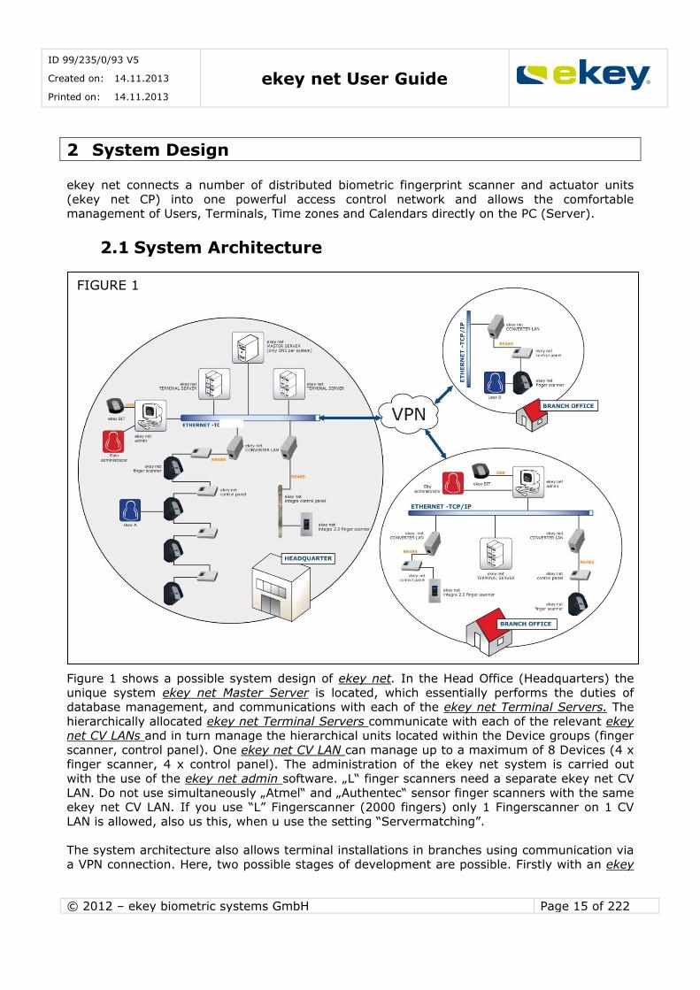
Figure 1 shows a possible system design of ekey net. In the Head Office (Headquarters) the
unique system ekey net Master Server is located, which essentially performs the duties of database management, and communications with each of the ekey net Terminal Servers. The
hierarchically allocated ekey net Terminal Servers communicate with each of the relevant ekey net CV LANs and in turn manage the hierarchical units located within the Device groups (finger
scanner, control panel). One ekey net CV LAN can manage up to a maximum of 8 Devices (4 x finger scanner, 4 x control panel). The administration of the ekey net system is carried out
with the use of the ekey net admin software. „L“ finger scanners need a separate ekey net CV
LAN. Do not use simultaneously „Atmel“ and „Authentec“ sensor finger scanners with the same ekey net CV LAN. If you use “L” Fingerscanner (2000 fingers) only 1 Fingerscanner on 1 CV
LAN is allowed, also us this, when u use the setting “Servermatching”.
The system architecture also allows terminal installations in branches using communication via a VPN connection. Here, two possible stages of development are possible. Firstly with an ekey
FIGURE 1
ID 99/235/0/93 V5
Created on: 14.11.2013
Printed on: 14.11.2013 ekey net User Guide
© 2012 – ekey biometric systems GmbH Page 16 of 222
net terminal server in the branch, or secondly using exclusively the connection over the ekey
net CV LAN, which can serve as a Terminal Server in small branches.
In systems where the ekey net Master Server is exclusively available, any number of ekey net Terminal Servers and ekey net admins in principle can be installed. However, there is the
constraint of the operating system itself. Windows Operating Systems which are not Server Operating Systems, allow up to 10 terminal servers or Terminal communications (there are
also other Terminal services such as ekey net Terminal Server, which allows the Master Server
to run). Physically, ekey net Master Server, ekey net Terminal Server and ekey net admin can operate on one computer, but can also be distributed and installed on individual computers. It
is only important that in this case the ekey Communication server is installed on every computer, and runs as a service.
The system service ekey Service Guard monitors all ekey net System services and
(re)starts these automatically. If the ekey net System services are to be stopped for maintenance, you must first stop the ekey Service Guard!
The basis of the communication is Microsoft Message Queuing (MSMQ). The data exchange between the Server services and ekey net CV LAN takes place via UDP packets. The data
exchange is not secure!
2.2 System Input Entries to the ekey net system can be made through the following interfaces:
ekey net admin ekey net FS
ekey net CP (only for Versions with digital input)
ekey net SDK (Software interface for ekey net -> it is not described in this User Guide).
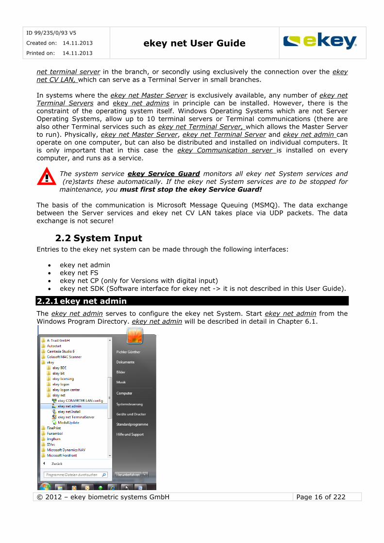
2.2.1 ekey net admin
The ekey net admin serves to configure the ekey net System. Start ekey net admin from the
Windows Program Directory. ekey net admin will be described in detail in Chapter 6.1.

ID 99/235/0/93 V5
Created on: 14.11.2013
Printed on: 14.11.2013 ekey net User Guide
© 2012 – ekey biometric systems GmbH Page 17 of 222
2.2.2 ekey net FS
ekey net FS concerns the scanning of the fingerprint and so the input of the user data during
operation. After the scanning of the fingerprint at the ekey net FS, a defined event can be triggered which in turn activates a certain action (assigned via the ekey net admin) on the
actuator units (ekey net CP).
2.2.3 ekey bit and ekey net desktop RFID reader
ekey bit is a fingerprint scanner with a USB interface. The fingerprint scanner in the ekey net
system is used for the storage (fingerprint recording) of the user finger. Thus, the User fingerprints are scanned centrally at the Administrator. The recorded ekey net fingerprints are
then implemented into the permission structure of ekey net FS and are distributed accordingly.
The ekey net desktop RFID reader records RFID cards to a user profile directly on the PC
workstation.
2.2.4 ekey net CP
An input into the ekey net System via the actuator is possible only with
ekey net CP IN (integra) ekey net CP mini
ekey net 4 CP REG
These device types make one or more digital inputs available for use, for example, door status
monitoring etc. See also Chapter 4.2.3.

ID 99/235/0/93 V5
Created on: 14.11.2013
Printed on: 14.11.2013 ekey net User Guide
© 2012 – ekey biometric systems GmbH Page 18 of 222
3 Licensing
3.1 License Model
ekey net is available with various licensing models, which include the ability to define the
scope of the system. The licensing options are:
LIGHT
COM BUSINESS (ekey net 3.x corresponds to the ekey net Business variant)
In the following chapters, these symbols are shown
if the parameter / function is available for the particular license mode.
The licensing model reflects a limited or full range of functions and should for you as the client, guarantee the optimal benefits for your application. The costs of the licenses vary of course
according to the particular license.
Roughly, it can be said:
Model “LIGHT”: for private users (limited functionality) Model “COM”: for printer applications and time recording (limited functionality)
Model “BUSINESS”: full version (the ekey net version 3.X corresponds to the Business
Version)
It is not possible to create hybrid forms. You can only operate the whole ekey net
System under one license. This means, when you acquire a finger scanner with the “BUSINESS” license, you cannot operate it in ekey net as a “LIGHT” variant!
3.2 Upgrade
ekey net can only upgraded from -> to the following LIGHT -> BUSINESS
COM -> BUSINESS It is not possible to change the license from LIGHT to COM. Furthermore, a downgrade from
BUSINESS to LIGHT / COM is also not possible.
BUSINESS
COM LIGHT

ID 99/235/0/93 V5
Created on: 14.11.2013
Printed on: 14.11.2013 ekey net User Guide
© 2012 – ekey biometric systems GmbH Page 19 of 222
3.3 Differences in the Licensing Models
The license models ekey net “Light” and ekey net “Com” are only available from Version 4.0. The License model “BUSINESS” is valid for ekey net
Version 3.5.
ekey net features depending on the license model:
ekey net FEATURES LICENSE MODELS
BUSINESS LIGHT COM*
Fingerscanner
hardware shapes wall-
mounted (WM), outlet-
mounted (OM), flush-mounted (IN) and door
handle (FSB)
WM, OM, IN,
FSB
WM, OM, IN,
FSB WM, OM, IN
Finger scanner sizes (S
= 40, M = 200, L =
2.000 fingerprints)
S, M, L S, M S, M, L
Number of time zones UNLIMITED 3 1 User groups UNLIMITED 1 UNLIMITED Terminal groups UNLIMITED 1 UNLIMITED
Max. number of sites
per each VPN
10
Max. number of
terminal
10
Amount of finger
scanners administrable
within an installation
80
Max. number of users
administrable within
an installation
4.000
Access YES YES NO
Number of time slots
per time zone
31 12 1
Attendance list YES NO NO
Calendar UNLIMITED 1 NON
Easy-Mode YES YES YES Enrollment via terminal
or USB
YES YES YES
Concierge mode YES NO NO
RFID YES YES YES
WIEGAND YES NO YES
Basic settings
adjustable
YES NO
(predefined)
YES (limited)
Customer-specified
actions and events
YES NO NO
E-Mail Notification YES NO NO

ID 99/235/0/93 V5
Created on: 14.11.2013
Printed on: 14.11.2013 ekey net User Guide
© 2012 – ekey biometric systems GmbH Page 20 of 222
CSV Logging YES Only positive YES
ekey-Reporting YES NO NO
ODBC(SQL) Logging YES NO YES
HTML Logging YES NO YES
UDP Logging YES YES YES
Time-controlled
operations
YES NO NO
Time-controlled anti-
pass back (min)
YES YES NO
Max. number of relays
tob e activated with 1
finger swipe
2 2 0
Mobile phone opening
via onetime PIN for increased security
YES YES NO
Offline capability YES YES YES
Number of relays 1 -
28
YES NO NO
Daytime operation
with or without first entry
YES YES NO
Area limit(s) YES YES NO
Multi-lingual software YES YES YES
Holiday calendar YES YES YES
* for time attendance only
3.4 License Key
As of Version 3.5, a license key is needed for the operation of ekey net FS in a system network.
You need License Keys for
The re-commission of ekey net FS in ekey net from Version 3.5. The update from ekey net 3.4 and older Versions to ekey net 4.0 for every Finger
Scanner (you get the license keys for free – see Chapter 5.3!)
For the Upgrade from ekey net Light (Com) to ekey net Business The Downgrade from ekey net FS with firmware version 5.X.X.X to Version 4.1.6.3 to
operate in ekey net systems older than Version 3.5
To order from ekey the appropriate licenses, you need to know what you want to do with the license (upgrade, downgrade, re-commission) and you need to know the number of Finger
Scanners. You must have a license for every Finger Scanner. The licenses can be purchased in packets of 1-30 pieces.
The license packages are indivisible and linked to the Master Server!

ID 99/235/0/93 V5
Created on: 14.11.2013
Printed on: 14.11.2013 ekey net User Guide
© 2012 – ekey biometric systems GmbH Page 21 of 222
ekey net business ekey net light
ekey net com ekey net Upgrade
ekey net Module Downgrade
3.5 License Manager
The License Manager is used to manage license keys for the ekey software components, ekey net / ekey logon etc. The License Manager is automatically installed on the Server / Computer,
and is also installed on the ekey net Master Server. In the License Manager, you can:
Add Licenses
Activate Licenses Online Activate Licenses Offline
Delete Licenses
Start the License Manager in the “Start Menu” -> “Program”-> “ekey” with a mouse click.
Editing licenses (adding, activating, importing…) in ekey net is always executed on the PC / Server, on which the ekey net Master Server is
installed!!!
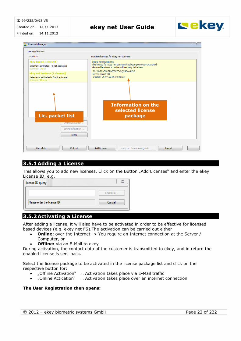
The License Manager opens. In the License package list (products) all ekey License packages are listed. Select a packet from there with a mouse click so you see in the right window,
information for the Packet e.g.:
ID 99/235/0/93 V5
Created on: 14.11.2013
Printed on: 14.11.2013 ekey net User Guide
© 2012 – ekey biometric systems GmbH Page 22 of 222
3.5.1 Adding a License
This allows you to add new licenses. Click on the Button „Add Licenses“ and enter the ekey
License ID, e.g.
3.5.2 Activating a License
After adding a license, it will also have to be activated in order to be effective for licensed
based devices (e.g. ekey net FS).The activation can be carried out either Online: over the Internet -> You require an Internet connection at the Server /
Computer, or Offline: via an E-Mail to ekey
During activation, the contact data of the customer is transmitted to ekey, and in return the
enabled license is sent back.
Select the license package to be activated in the license package list and click on the respective button for:
„Offline Activation“ … Activation takes place via E-Mail traffic „Online Actication“ … Activation takes place over an internet connection
The User Registration then opens:
Lic. packet list
Information on the selected license
package
ID 99/235/0/93 V5
Created on: 14.11.2013
Printed on: 14.11.2013 ekey net User Guide
© 2012 – ekey biometric systems GmbH Page 23 of 222
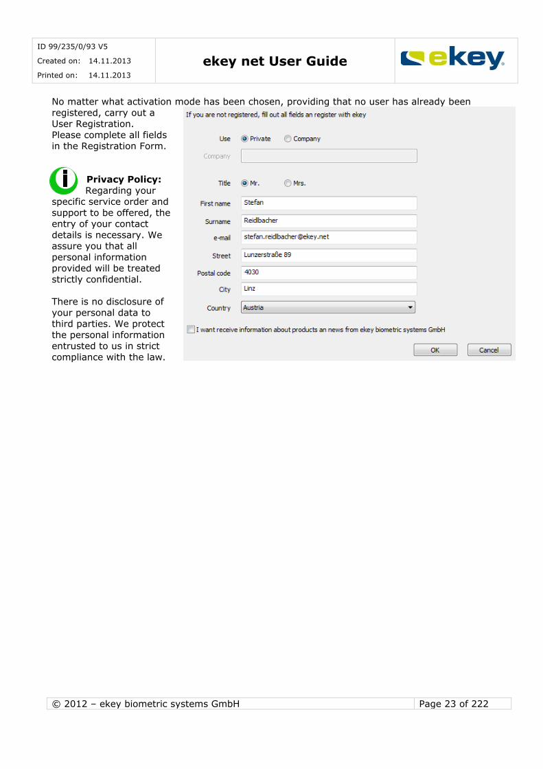
No matter what activation mode has been chosen, providing that no user has already been
registered, carry out a User Registration.
Please complete all fields in the Registration Form.
Privacy Policy:
Regarding your specific service order and
support to be offered, the entry of your contact
details is necessary. We assure you that all
personal information provided will be treated
strictly confidential.
There is no disclosure of
your personal data to third parties. We protect
the personal information entrusted to us in strict
compliance with the law.
ID 99/235/0/93 V5
Created on: 14.11.2013
Printed on: 14.11.2013 ekey net User Guide
© 2012 – ekey biometric systems GmbH Page 24 of 222
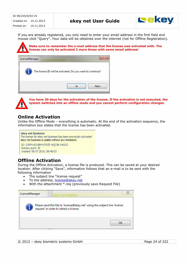
If you are already registered, you only need to enter your email address in the first field and
mouse click “Query”. Your data will be obtained over the internet (not for Offline Registration).
Make sure to remember the e-mail address that the license was activated with. The license can only be activated 2 more times with same email address!
You have 30 days for the activation of the license. If the activation is not executed, the system switches into an offline mode and you cannot perform configuration changes.
Online Activation Unlike the Offline Mode – everything is automatic. At the end of the activation sequence, the information box states that the license has been activated.
Offline Activation During the Offline Activation, a license file is produced. This can be saved at your desired location. After clicking “Save”, information follows that an e-mail is to be sent with the
following information The subject line “license request”
To the address, [email protected]
With the attachment *.req (previously save Request File)

ID 99/235/0/93 V5
Created on: 14.11.2013
Printed on: 14.11.2013 ekey net User Guide
© 2012 – ekey biometric systems GmbH Page 25 of 222
When using MS Outlook for your e-mail traffic, the mail client opens automatically and all
necessary data will be entered. Now, you only need to send your e-mail.
Do not change the above e-mail and send it by clicking on the “Send” button.
When using a different e-mail client other than MS Outlook, please send your e-mail with the following content:
SUBJECT: license request V2 Attach the previously created ekey license file (.req).
On receipt of your e-mail, ekey will send you the activated license container back within 1-2
working days. The activated license will be supplied in the form of a file (*.act).You can save this returned file (*.act) from ekey anywhere on your computer.
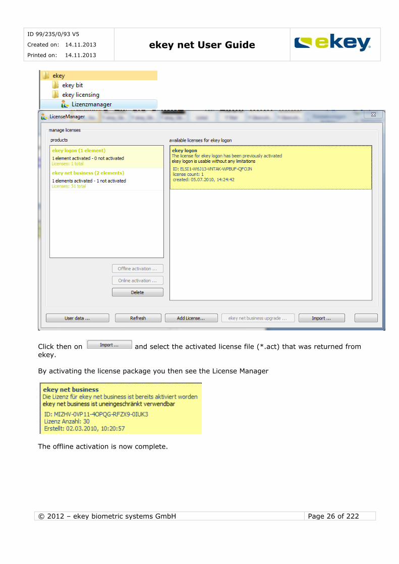
Start the License Manager in “Start Menu” -> “Programs”-> “ekey” with a single click.
ID 99/235/0/93 V5
Created on: 14.11.2013
Printed on: 14.11.2013 ekey net User Guide
© 2012 – ekey biometric systems GmbH Page 26 of 222
Click then on and select the activated license file (*.act) that was returned from
ekey.
By activating the license package you then see the License Manager
The offline activation is now complete.
ID 99/235/0/93 V5
Created on: 14.11.2013
Printed on: 14.11.2013 ekey net User Guide
© 2012 – ekey biometric systems GmbH Page 27 of 222
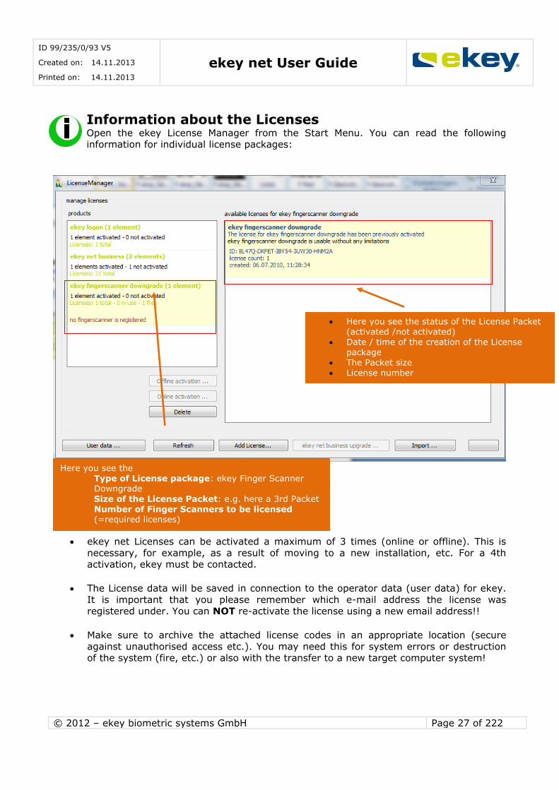
Information about the Licenses Open the ekey License Manager from the Start Menu. You can read the following information for individual license packages:
ekey net Licenses can be activated a maximum of 3 times (online or offline). This is
necessary, for example, as a result of moving to a new installation, etc. For a 4th activation, ekey must be contacted.
The License data will be saved in connection to the operator data (user data) for ekey.
It is important that you please remember which e-mail address the license was
registered under. You can NOT re-activate the license using a new email address!!
Make sure to archive the attached license codes in an appropriate location (secure
against unauthorised access etc.). You may need this for system errors or destruction of the system (fire, etc.) or also with the transfer to a new target computer system!
Here you see the Type of License package: ekey Finger Scanner Downgrade
Size of the License Packet: e.g. here a 3rd Packet Number of Finger Scanners to be licensed (=required licenses)
Here you see the status of the License Packet (activated /not activated)
Date / time of the creation of the License package
The Packet size
License number

ID 99/235/0/93 V5
Created on: 14.11.2013
Printed on: 14.11.2013 ekey net User Guide
© 2012 – ekey biometric systems GmbH Page 28 of 222
4 Devices
ekey net connects a variety of devices to a complete system, which are managed centrally with ekey net. In the following chapters you will learn about the individual devices and their role in
the complete system.
4.1 Device Types The following devices can operate in ekey net:
The list of Devices is reflected by the date of creation of this User Guide. New device
types are always being created. Check directly with ekey for currently available Devices.
Device Description Symbol Performance Description
ekey net S FS WM
40 Fingers Wall mounted Suitable for outdoor use
ekey net M FS WM
200 Fingers Wall mounted Suitable for outdoor use
ekey net L FS WM
2000 Fingers (200 Fingers in
ekey net light)
Wall mounted Suitable for outdoor use
ekey net S FS IN
40 Fingers Flush mounted
Suitable for outdoor use
ekey net M FS IN
200 Fingers Flush mounted Suitable for outdoor use
ekey net L FS IN
2000 Fingers (200 Fingers in ekey net light)
Flush mounted Suitable for outdoor use
ekey net S FS RFID
40 Fingers + RFID Interface
RFID-Functionality Wall mounted
Suitable for outdoor use
ekey net M FS RFID
200 Fingers + RFID Interface
RFID-Functionality Wall mounted Suitable for outdoor use
ekey net L FS RFID
2000 Fingers + RFID Interface
(200 Fingers in ekey net light)
RFID-Functionality Wall mounted
Suitable for outdoor use
Feller net S (M,L) FS UP
40/200/2000 Fingers
Socket-mounted / recessed Suitable for outdoor use
Feller net S (M,L) FS UP REL
40/200/2000 Fingers
Socket-mounted / recessed For REL use
FSB net S (M,L) FS
40/200/2000
Fingers
Door installation
For outdoor use
Device Description Symbol Performance Description
ID 99/235/0/93 V5
Created on: 14.11.2013
Printed on: 14.11.2013 ekey net User Guide
© 2012 – ekey biometric systems GmbH Page 29 of 222
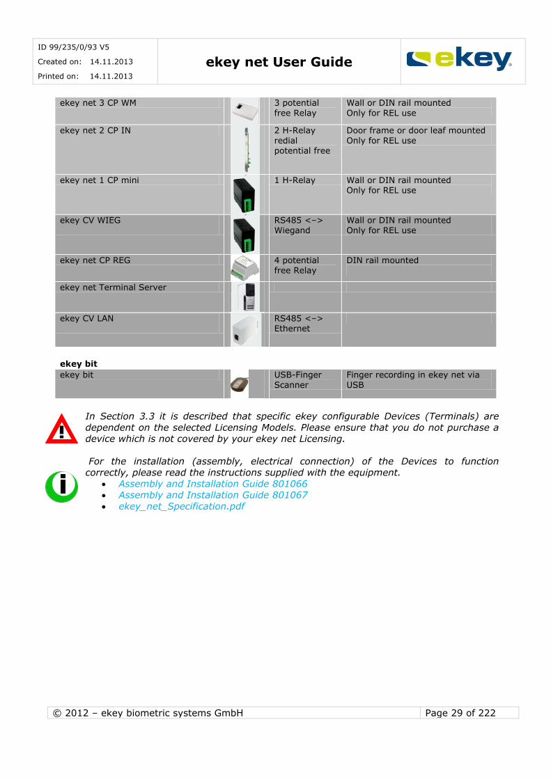
ekey net 3 CP WM
3 potential
free Relay
Wall or DIN rail mounted
Only for REL use
ekey net 2 CP IN
2 H-Relay
redial potential free
Door frame or door leaf mounted
Only for REL use
ekey net 1 CP mini
1 H-Relay Wall or DIN rail mounted Only for REL use
ekey CV WIEG
RS485 <–> Wiegand
Wall or DIN rail mounted Only for REL use
ekey net CP REG
4 potential free Relay
DIN rail mounted
ekey net Terminal Server
ekey CV LAN
RS485 <–> Ethernet
ekey bit
ekey bit
USB-Finger
Scanner
Finger recording in ekey net via
USB
In Section 3.3 it is described that specific ekey configurable Devices (Terminals) are
dependent on the selected Licensing Models. Please ensure that you do not purchase a device which is not covered by your ekey net Licensing.
For the installation (assembly, electrical connection) of the Devices to function correctly, please read the instructions supplied with the equipment.
Assembly and Installation Guide 801066 Assembly and Installation Guide 801067
ekey_net_Specification.pdf

ID 99/235/0/93 V5
Created on: 14.11.2013
Printed on: 14.11.2013 ekey net User Guide
© 2012 – ekey biometric systems GmbH Page 30 of 222
4.2 Functions of the Devices in ekey net
Individual Devices have different roles in ekey net. To understand the configuration with more clarity and transparency, it is recommended to go through this chapter.
4.2.1 ekey net FS (Finger Scanner)
ekey net FS are biometric sensor units which scan the fingerprints of the user, analyse and
trigger the following Events. The ekey net FS
record the Fingerprints (swipe the finger over the Sensor) creates Templates from the recorded finger image
compare the recorded fingerprint with the legitimate fingerprint templates which are stored on the Finger Scanner
store the legitimate Finger Templates store the User ID
store the access restrictions (time zones, calendar etc.)
store the Event definitions trigger defined events in dependence with the scanned finger and assigned
access rights.
If a finger is swiped over the Scanner, this leads to an Event. What Event however, must be defined prior in ekey net. Events are always associated with a finger. A finger can, in principle,
trigger one event only.
ID 99/235/0/93 V5
Created on: 14.11.2013
Printed on: 14.11.2013 ekey net User Guide
© 2012 – ekey biometric systems GmbH Page 31 of 222
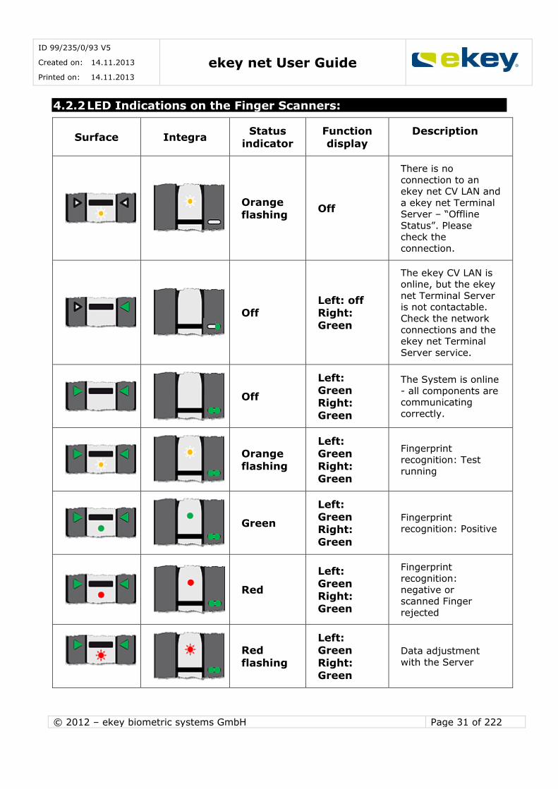
4.2.2 LED Indications on the Finger Scanners:
Surface Integra Status
indicator
Function
display
Description
Orange
flashing Off
There is no
connection to an ekey net CV LAN and
a ekey net Terminal Server – “Offline
Status”. Please check the
connection.
Off
Left: off
Right: Green
The ekey CV LAN is online, but the ekey
net Terminal Server is not contactable.
Check the network
connections and the ekey net Terminal
Server service.
Off
Left: Green
Right:
Green
The System is online
- all components are communicating
correctly.
Orange
flashing
Left:
Green
Right:
Green
Fingerprint recognition: Test
running
Green
Left:
Green Right:
Green
Fingerprint recognition: Positive
Red
Left:
Green
Right: Green
Fingerprint
recognition: negative or
scanned Finger
rejected
Red
flashing
Left:
Green
Right:
Green
Data adjustment
with the Server

ID 99/235/0/93 V5
Created on: 14.11.2013
Printed on: 14.11.2013 ekey net User Guide
© 2012 – ekey biometric systems GmbH Page 32 of 222
Off
Alternate
Left Right
Green flashing
Firmware Update will
be performed
Red
Green flashing
Left:
Green
Right:
Green
2 Finger or 2 Person mode:
The Device is waiting for the second
finger.
Red
Orange
flashing
Left: Green
Right:
Green
Waiting for triggered
Reboot Action from
the Finger Scanner
During the boot process:
Yellow Off Module database is
initialised
Green –
Yellow Off
Flash error -
automatic repair has started
Red -
Red -
Yellow
Off
Flash error - the
Finger Scanner must be replaced – please
get in contact with Support.
Red Green
flashing
Off
Communication with
the Scanner was not possible during the
boot process - please get in contact
with Support.
4.2.3 ekey net Control Panel (CP) – ekey net Composite CP
The ekey net CP and the ekey net CV WIEG are Actuator Units. These units perform an Action: e.g. Switching pulse of 3 sec on relay output 1 = Impulse relay output 1. ekey net CP

ID 99/235/0/93 V5
Created on: 14.11.2013
Printed on: 14.11.2013 ekey net User Guide
© 2012 – ekey biometric systems GmbH Page 33 of 222
switch relay output – or solid state relay
switch Impulse – or activate keep-switched function send data to external systems (e.g. Wiegand)
Provide feedback to the system via digital inputs (ekey net CP Mini)
The Actions triggered by the Control Panel are defined in the software application ekey net. For their execution they have to be associated with a specific Event.
Using an ekey net composite control panel the number of switchable relays, max. 4 relays on ekey net CP (varies with Model 1 to 4) increases up to a max. of 28 relays with 7 ekey net
CP in combination. See Chapter 6.6.3.2.2.
4.2.4 The 7-Segment Control Panel Display
Display Info Description
Both Points are illuminated
The Terminal is new and is not yet
initialised. The status may be forced by pressing both left and
right keys.
"r" in the right
Segment and flashing Points
that alternate
This Terminal was initialised in
another ekey net System. A reset is required by pressing the left
and right keys.
"o" in the right
Segment
There is no connection to an ekey
CV LAN and an ekey net Terminal
Server – “Offline – Status”. Please check the connection.
Left Point flashes
The ekey CV LAN is online, but
the Terminal Server is not contactable. Check the network
connections and the ekey net Terminal Server service.
Points flash
alternately
The System is online - all
components are communicating correctly.
4.2.5 ekey bit
ekey bit is a USB Finger Scanner which is used initially or for repeated Fingerprint
recording in ekey net (recording of the Fingerprint Template for each user).

ID 99/235/0/93 V5
Created on: 14.11.2013
Printed on: 14.11.2013 ekey net User Guide
© 2012 – ekey biometric systems GmbH Page 34 of 222
4.2.6 ekey net CV (converter) LAN
The ekey net CV LAN can be described as a Data Converter for
the physical implementation of RS485 to Ethernet
the administration of its associated Devices on RS485 – transfer side An ekey net CV LAN can manage up to 8 Devices on the RS485 Bus, it is irrelevant what type
of ekey net Device (Finger Scanner, Control Panel ...) is turned on.
4.2.7 ekey net Terminal Server
The ekey net Terminal Server is a System service on a PC / Server with a Windows Operating
System running. The tasks of this Service are:
the management of allocated Terminal Groups and Devices Server matching
Caching of log data Communication with the ekey net Master Server
WEB Logging
Please refer to ekey net specifications for which Windows Operating Systems can be used for
the operation of ekey net Terminal Servers.
4.2.8 ekey net Master Server
The ekey net Master Server is a System service on a PC / Server with a Windows Operating System running. In each system only 1 ekey net Master Server can exist. The tasks of this
Service are:
the management of allocated Terminal Servers Data storage and database management
Please refer to ekey net specifications for which Windows Operating Systems can be used for
the operation of ekey net Master Servers.
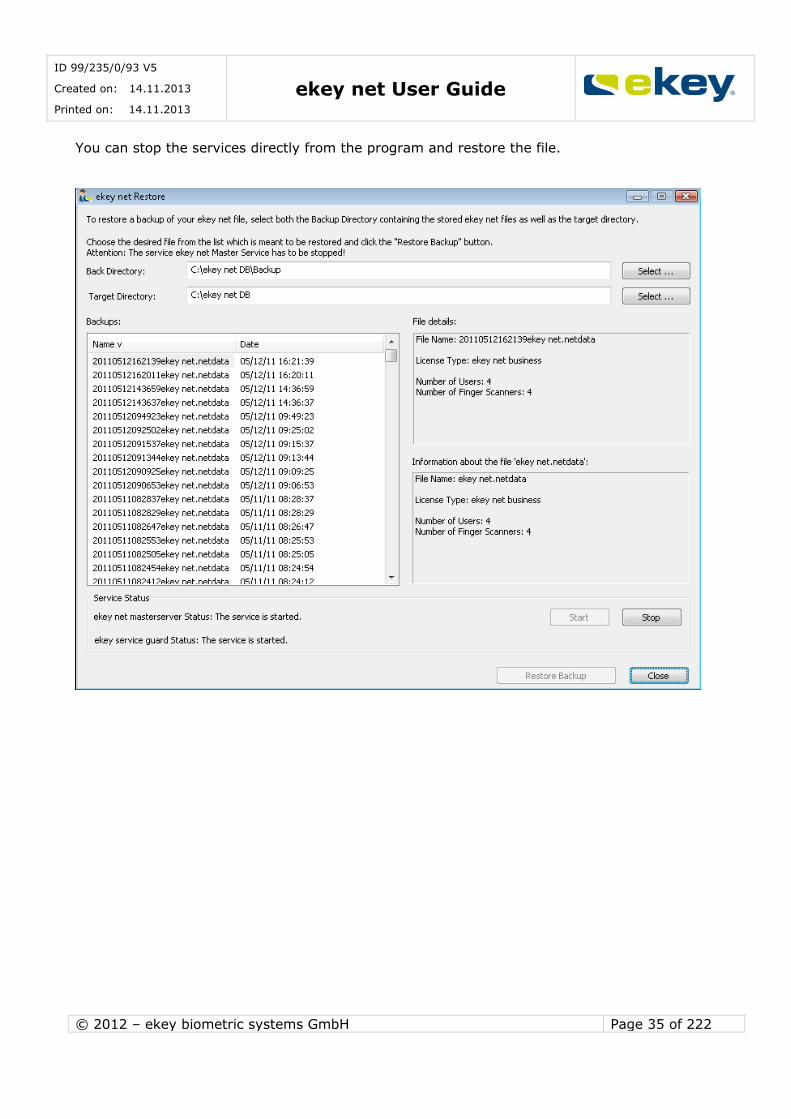
4.2.9 ekey net Restore
ekey net version 4.1 features a new program, „ekey net Restore“, which you can find under
Start/Programs/ekey/ekey net/.
This tool allows you to restore an older version of your config in case a user, or the current file,
has been deleted by mistake.
Simply select the backup folder and the folder where your current „ekey netdata“ file has been saved.
ID 99/235/0/93 V5
Created on: 14.11.2013
Printed on: 14.11.2013 ekey net User Guide
© 2012 – ekey biometric systems GmbH Page 35 of 222
You can stop the services directly from the program and restore the file.

ID 99/235/0/93 V5
Created on: 14.11.2013
Printed on: 14.11.2013 ekey net User Guide
© 2012 – ekey biometric systems GmbH Page 36 of 222
5 Software Installation
5.1 Installation Preparation
Before you start installing (both hardware and software) any components from ekey net, we
recommend that you make a system overview and a plan. This will help you put them into operation and also with configuration:
Define (or ask your IT Department to define)
the physical installation location of the ekey net Master Server the physical installation location(s) of the ekey net Terminal Server(s)
how will the ekey net CV LAN(s) assigned to the Terminal Server(s)? which Terminal (Finger Scanner, Control Unit) is allocated to which CV LAN?
give each Device a self-explanatory, understandable name!
You need the following data for the installation and configuration (consult with your
IT department or your IT specialists). Collect this data before the beginning of the installation.
Host (computer) name of the ekey net Master Server (to be defined by you or your IT
Department)
Host (computer) name of the ekey net Terminal Server(s) (to be defined by you or your IT Department)
IP Addresses of the ekey net CV LAN (defined by you or your IT Department) MAC Addresses of the ekey net CV LAN (see the serial number label (12 digit
hexadecimal, e.g. 00 20 4a ba 12 0d)) Serial number and Device type of the Terminals (finger scanner, control panel) can be
found on the serial number label on the Device (14 digit, e.g. 80034020090004)
For the minimum requirements for the target system on which ekey net should be operated,
see the ekey net specification.
Before starting the installation of ekey net on your target system, please check the following settings
Computer performance (ekey_net_Specification -> Chapter 4.1) Operating system (ekey_net_Specification -> Chapter 2.2)
Network settings (ekey_net_Specification -> Chapter 2.3) Wiring / Installation (ekey_net_Specification -> Chapter 4)
In the Network, it must be ensured, that the computer (server) on which the ekey net Master Server Services and Terminal
Server, and the application ekey net Admin with Names (DNS) are mutually accessible.
that the above Servers are synchronized.The time difference among the computers
(Servers) must not exceed 10 seconds (security function)
For the implementation of the Installation Chapter to proceed, all Devices must be
connected properly, are powered, and connected to the network (Ethernet).
ID 99/235/0/93 V5
Created on: 14.11.2013
Printed on: 14.11.2013 ekey net User Guide
© 2012 – ekey biometric systems GmbH Page 37 of 222
5.2 Carrying out the Installation
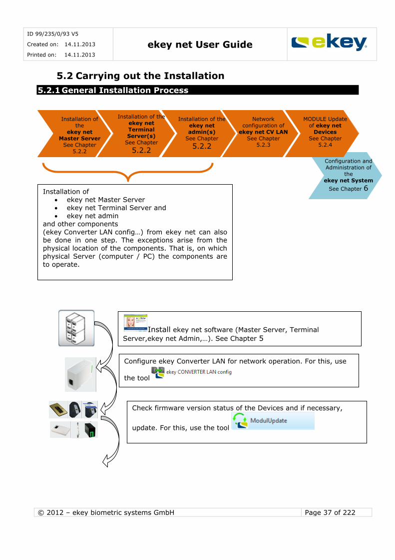
5.2.1 General Installation Process
Installation of
the
ekey net
Master Server
See Chapter
5.2.2
Installation of the
ekey net
Terminal
Server(s)
See Chapter
5.2.2
Network
configuration of
ekey net CV LAN
See Chapter 5.2.3
Installation of the
ekey net
admin(s)
See Chapter
5.2.2
Configuration and
Administration of
the
ekey net System
See Chapter 6 Installation of ekey net Master Server
ekey net Terminal Server and ekey net admin
and other components
(ekey Converter LAN config…) from ekey net can also be done in one step. The exceptions arise from the
physical location of the components. That is, on which physical Server (computer / PC) the components are
to operate.
Install ekey net software (Master Server, Terminal
Server,ekey net Admin,…). See Chapter 5
Configure ekey Converter LAN for network operation. For this, use
the tool
MODULE Update
of ekey net
Devices
See Chapter 5.2.4
Check firmware version status of the Devices and if necessary,
update. For this, use the tool
ID 99/235/0/93 V5
Created on: 14.11.2013
Printed on: 14.11.2013 ekey net User Guide
© 2012 – ekey biometric systems GmbH Page 38 of 222
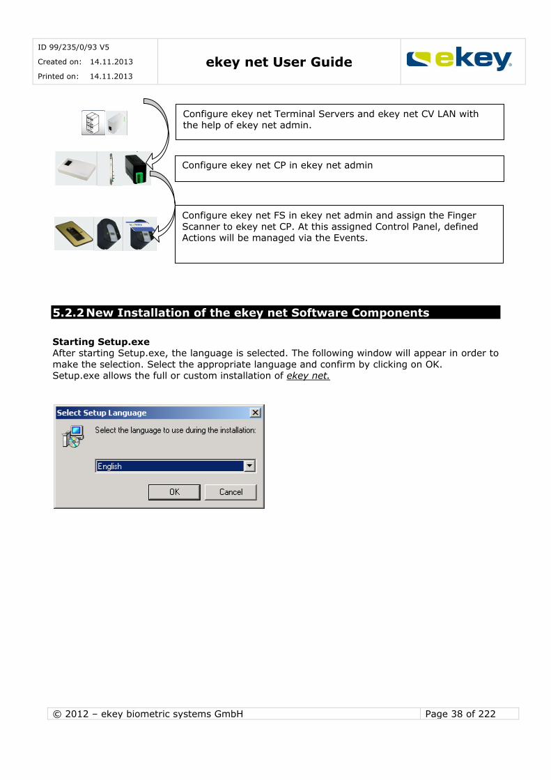
5.2.2 New Installation of the ekey net Software Components
Starting Setup.exe After starting Setup.exe, the language is selected. The following window will appear in order to
make the selection. Select the appropriate language and confirm by clicking on OK. Setup.exe allows the full or custom installation of ekey net.
Configure ekey net CP in ekey net admin
Configure ekey net FS in ekey net admin and assign the Finger
Scanner to ekey net CP. At this assigned Control Panel, defined Actions will be managed via the Events.
Configure ekey net Terminal Servers and ekey net CV LAN with the help of ekey net admin.

ID 99/235/0/93 V5
Created on: 14.11.2013
Printed on: 14.11.2013 ekey net User Guide
© 2012 – ekey biometric systems GmbH Page 39 of 222
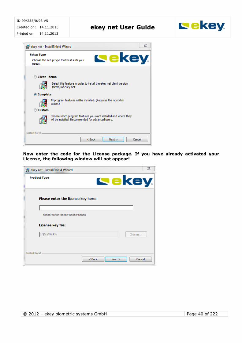
The ekey net InstallShield Wizard then starts
Confirm this with
The License Agreement Window opens. Please read through this and confirm by selecting the
field “I accept the terms of the licensing agreement”
and subsequently click on
ID 99/235/0/93 V5
Created on: 14.11.2013
Printed on: 14.11.2013 ekey net User Guide
© 2012 – ekey biometric systems GmbH Page 40 of 222
Now enter the code for the License package. If you have already activated your
License, the following window will not appear!
ID 99/235/0/93 V5
Created on: 14.11.2013
Printed on: 14.11.2013 ekey net User Guide
© 2012 – ekey biometric systems GmbH Page 41 of 222
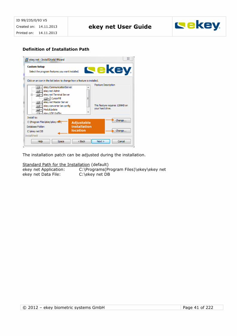
Definition of Installation Path
The installation patch can be adjusted during the installation.
Standard Path for the Installation (default)
ekey net Application: C:\Programs(Program Files)\ekey\ekey net
ekey net Data File: C:\ekey net DB
Adjustable
installation
location

ID 99/235/0/93 V5
Created on: 14.11.2013
Printed on: 14.11.2013 ekey net User Guide
© 2012 – ekey biometric systems GmbH Page 42 of 222
Avoid database folders using UNC paths or network drives to avoid problems concerning permissions. The service account for the Master Server service must have
full access to this folder!
Selecting the Components to install from ekey net
The following components must be installed in the complete system for the proper operation of ekey net.
ekey Communication Server
Function: ekey Communication Server manages the ekey net network communication based on MSMQ (Microsoft Message Queuing). This service must be installed on every
computer in ekey net. This is particularly true for the Server services, ekey net Master Server and ekey net Terminal Server and also for the ekey net admin.
ekey net admin Function: This program can be installed on any number of computers and assists the
ekey net Administrators with managing and setting parameters for ekey net. This software application is also used for the Doorman mode.
ekey net Master Server
Function: Database administration, where all system data (personal data, terminal
data, access data, …) is stored centrally. For each ekey net installation, only one ekey
net Master Server can be active.
ekey net Terminal Server
It is responsible for the distribution of access data from ekey net Master Server to the
Devices and back, monitoring of the Devices etc. Every installation can have any number of ekey net Terminal Servers active (restrictions imposed from the Operating
System are possible!).
ekey converter LAN config Lists the available ekey net CV LANs in the local network and allows network
configuration and firmware updates of individual ekey net CV LANs.
ID 99/235/0/93 V5
Created on: 14.11.2013
Printed on: 14.11.2013 ekey net User Guide
© 2012 – ekey biometric systems GmbH Page 43 of 222
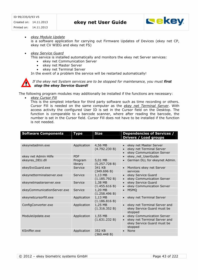
ekey Module Update
is a software application for carrying out Firmware Updates of Devices (ekey net CP, ekey net CV WIEG and ekey net FS)
ekey Service Guard
This service is installed automatically and monitors the ekey net Server services: ekey net Communication Server
ekey net Master Server
ekey net Terminal Server In the event of a problem the service will be restarted automatically!
If the ekey net System services are to be stopped for maintenance, you must first
stop the ekey Service Guard!
The following program modules may additionally be installed if the functions are necessary: ekey Cursor Fill
This is the simplest interface for third party software such as time recording or others.
Cursor Fill is needed on the same computer as the ekey net Terminal Server. With access activity the configured User ID is set in the Cursor field on the Desktop. The
function is comparable to a barcode scanner, where after reading the barcode, the number is set in the Cursor field. Cursor Fill does not have to be installed if the function
is not needed.
Software Components Type Size Dependencies of Services /
Drivers / Load groups
ekeynetadmin.exe Application 4,56 MB
(4.792.230 B)
ekey net Master Server
ekey net Terminal Server ekey Communication Server
ekey net Admin Hilfe PDF ekey_net_UserGuide
ekeyres_DEU.dll Program
library
5,01 MB
(5.257.728 B)
German DLL for ekeynet Admin.
ekeySvcGuard.exe Service 341 KB (349.696 B)
Monitors ekey net Server services
ekeynetterminalserver.exe Service 1,13 MB (1.185.792 B)
ekey Service Guard ekey Communication Server
ekeynetmasterserver.exe Service 1,38 MB (1.455.616 B)
ekey Service Guard ekey Communication Server
ekeyCommunicationServer.exe Service 1,20 MB (1.258.496 B)
MSMQ
ekeynetcursorfill.exe Application 1,13 MB (1.186.816 B)
ekey net Terminal Server
ConfigConverter.exe Application 1,25 MB (1.316.352 B)
ekey net Terminal Server and ekey Service Guard must be stopped
ModuleUpdate.exe Application 1,55 MB (1.631.232 B)
ekey Communication Server ekey net Terminal Server and
ekey Service Guard must be stopped
KSniffer.exe Application 352 KB
(360.448 B)
None
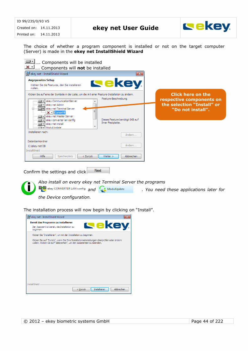
ID 99/235/0/93 V5
Created on: 14.11.2013
Printed on: 14.11.2013 ekey net User Guide
© 2012 – ekey biometric systems GmbH Page 44 of 222
The choice of whether a program component is installed or not on the target computer
(Server) is made in the ekey net InstallShield Wizard
…. Components will be installed
…. Components will not be installed
Confirm the settings and click
Also install on every ekey net Terminal Server the programs
ekey net CV LAN confi and ModulUpdate . You need these applications later for
the Device configuration.
The installation process will now begin by clicking on “Install”.
Click here on the respective components on
the selection “Install” or “Do not install”.
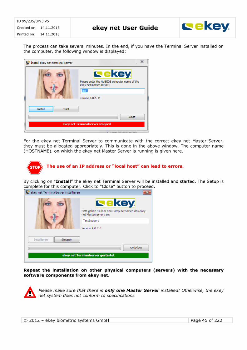
ID 99/235/0/93 V5
Created on: 14.11.2013
Printed on: 14.11.2013 ekey net User Guide
© 2012 – ekey biometric systems GmbH Page 45 of 222
The process can take several minutes. In the end, if you have the Terminal Server installed on
the computer, the following window is displayed:
For the ekey net Terminal Server to communicate with the correct ekey net Master Server,
they must be allocated appropriately. This is done in the above window. The computer name (HOSTNAME), on which the ekey net Master Server is running is given here.
The use of an IP address or “local host” can lead to errors.
By clicking on “Install” the ekey net Terminal Server will be installed and started. The Setup is complete for this computer. Click to “Close” button to proceed.
Repeat the installation on other physical computers (servers) with the necessary
software components from ekey net.
Please make sure that there is only one Master Server installed! Otherwise, the ekey
net system does not conform to specifications
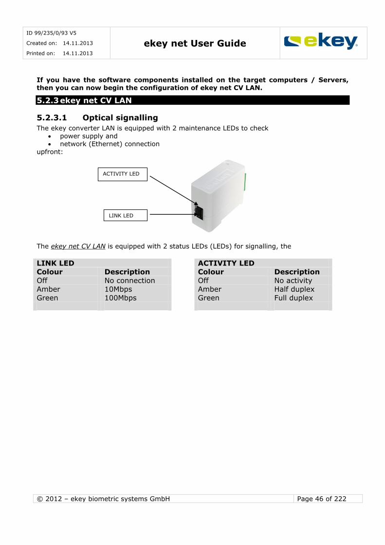
ID 99/235/0/93 V5
Created on: 14.11.2013
Printed on: 14.11.2013 ekey net User Guide
© 2012 – ekey biometric systems GmbH Page 46 of 222
If you have the software components installed on the target computers / Servers, then you can now begin the configuration of ekey net CV LAN.
5.2.3 ekey net CV LAN
5.2.3.1 Optical signalling
The ekey converter LAN is equipped with 2 maintenance LEDs to check
power supply and network (Ethernet) connection
upfront:
The ekey net CV LAN is equipped with 2 status LEDs (LEDs) for signalling, the
LINK LED ACTIVITY LED Colour Description Colour Description
Off No connection Off No activity
Amber 10Mbps Amber Half duplex
Green 100Mbps Green Full duplex
ACTIVITY LED
LINK LED
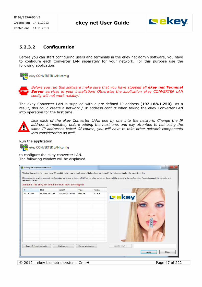
ID 99/235/0/93 V5
Created on: 14.11.2013
Printed on: 14.11.2013 ekey net User Guide
© 2012 – ekey biometric systems GmbH Page 47 of 222
5.2.3.2 Configuration
Before you can start configuring users and terminals in the ekey net admin software, you have to configure each Converter LAN separately for your network. For this purpose use the
following application:
Before you run this software make sure that you have stopped all ekey net Terminal
Server services in your installation! Otherwise the application ekey CONVERTER LAN config will not work reliably!
The ekey Converter LAN is supplied with a pre-defined IP address (192.168.1.250). As a
result, this could create a network / IP address conflict when taking the ekey Converter LAN into operation for the first time.
Link each of the ekey Converter LANs one by one into the network. Change the IP address immediately before adding the next one, and pay attention to not using the
same IP addresses twice! Of course, you will have to take other network components into consideration as well.
Run the application
to configure the ekey converter LAN.
The following window will be displayed
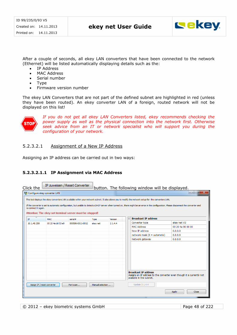
ID 99/235/0/93 V5
Created on: 14.11.2013
Printed on: 14.11.2013 ekey net User Guide
© 2012 – ekey biometric systems GmbH Page 48 of 222
After a couple of seconds, all ekey LAN converters that have been connected to the network (Ethernet) will be listed automatically displaying details such as the:
IP Address MAC Address
Serial number
Type Firmware version number
The ekey LAN Converters that are not part of the defined subnet are highlighted in red (unless
they have been routed). An ekey converter LAN of a foreign, routed network will not be displayed on this list!
If you do not get all ekey LAN Converters listed, ekey recommends checking the
power supply as well as the physical connection into the network first. Otherwise
seek advice from an IT or network specialist who will support you during the configuration of your network.
5.2.3.2.1 Assignment of a New IP Address
Assigning an IP address can be carried out in two ways:
5.2.3.2.1.1 IP Assignment via MAC Address
Click the button. The following window will be displayed.
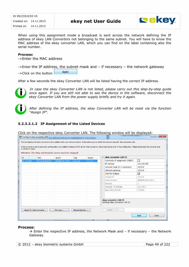
ID 99/235/0/93 V5
Created on: 14.11.2013
Printed on: 14.11.2013 ekey net User Guide
© 2012 – ekey biometric systems GmbH Page 49 of 222
When using this assignment mode a broadcast is sent across the network defining the IP
address of ekey LAN Converters not belonging to the same subnet. You will have to know the MAC address of the ekey converter LAN, which you can find on the label containing also the
serial number.
Process:
->Enter the MAC address
->Enter the IP address, the subnet mask and – if necessary – the network gateway
->Click on the button
After a few seconds the ekey Converter LAN will be listed having the correct IP address.
In case the ekey Converter LAN is not listed, please carry out this step-by-step guide once again. If you are still not able to see the device in the software, disconnect the
ekey Converter LAN from the power supply briefly and try it again.
After defining the IP address, the ekey Converter LAN will be reset via the function
“Assign IP”.
5.2.3.2.1.2 IP Assignment of the Listed Devices
Click on the respective ekey Converter LAN. The following window will be displayed:
Process: Enter the respective IP address, the Network Mask and – if necessary – the Network Gateway.
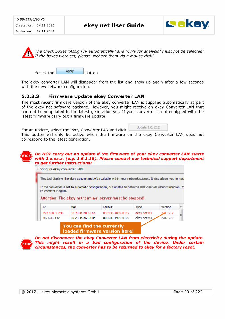
ID 99/235/0/93 V5
Created on: 14.11.2013
Printed on: 14.11.2013 ekey net User Guide
© 2012 – ekey biometric systems GmbH Page 50 of 222
The check boxes “Assign IP automatically” and “Only for analysis” must not be selected!
If the boxes were set, please uncheck them via a mouse click!
click the button
The ekey converter LAN will disappear from the list and show up again after a few seconds
with the new network configuration.
5.2.3.3 Firmware Update ekey Converter LAN
The most recent firmware version of the ekey converter LAN is supplied automatically as part
of the ekey net software package. However, you might receive an ekey Converter LAN that had not been updated to the latest generation yet. If your converter is not equipped with the
latest firmware carry out a firmware update.
For an update, select the ekey Converter LAN and click .
This button will only be active when the firmware on the ekey Converter LAN does not correspond to the latest generation.
Do NOT carry out an update if the firmware of your ekey converter LAN starts
with 1.x.xx.x. (e.g. 1.6.1.16). Please contact our technical support department to get further instructions!
Do not disconnect the ekey Converter LAN from electricity during the update. This might result in a bad configuration of the device. Under certain
circumstances, the converter has to be returned to ekey for a factory reset.
You can find the currently loaded firmware version here!
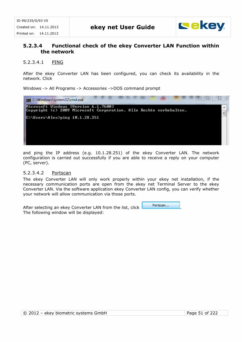
ID 99/235/0/93 V5
Created on: 14.11.2013
Printed on: 14.11.2013 ekey net User Guide
© 2012 – ekey biometric systems GmbH Page 51 of 222
5.2.3.4 Functional check of the ekey Converter LAN Function within
the network
5.2.3.4.1 PING
After the ekey Converter LAN has been configured, you can check its availability in the network. Click
Windows -> All Programs -> Accessories ->DOS command prompt
and ping the IP address (e.g. 10.1.28.251) of the ekey Converter LAN. The network
configuration is carried out successfully if you are able to receive a reply on your computer
(PC, server).
5.2.3.4.2 Portscan
The ekey Converter LAN will only work properly within your ekey net installation, if the
necessary communication ports are open from the ekey net Terminal Server to the ekey Converter LAN. Via the software application ekey Converter LAN config, you can verify whether
your network will allow communication via those ports.
After selecting an ekey Converter LAN from the list, click . The following window will be displayed:
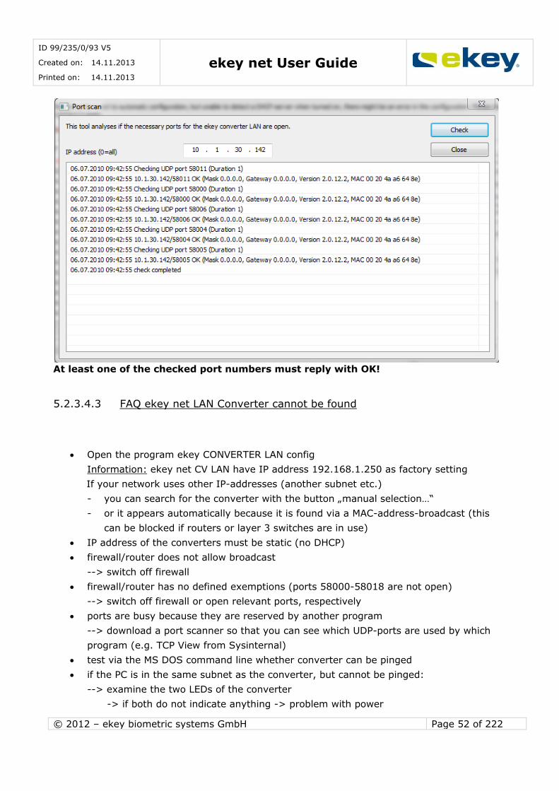
ID 99/235/0/93 V5
Created on: 14.11.2013
Printed on: 14.11.2013 ekey net User Guide
© 2012 – ekey biometric systems GmbH Page 52 of 222
At least one of the checked port numbers must reply with OK!
5.2.3.4.3 FAQ ekey net LAN Converter cannot be found
Open the program ekey CONVERTER LAN config
Information: ekey net CV LAN have IP address 192.168.1.250 as factory setting
If your network uses other IP-addresses (another subnet etc.)
- you can search for the converter with the button „manual selection…“
- or it appears automatically because it is found via a MAC-address-broadcast (this
can be blocked if routers or layer 3 switches are in use)
IP address of the converters must be static (no DHCP)
firewall/router does not allow broadcast
--> switch off firewall
firewall/router has no defined exemptions (ports 58000-58018 are not open)
--> switch off firewall or open relevant ports, respectively
ports are busy because they are reserved by another program
--> download a port scanner so that you can see which UDP-ports are used by which
program (e.g. TCP View from Sysinternal)
test via the MS DOS command line whether converter can be pinged
if the PC is in the same subnet as the converter, but cannot be pinged:
--> examine the two LEDs of the converter
-> if both do not indicate anything -> problem with power
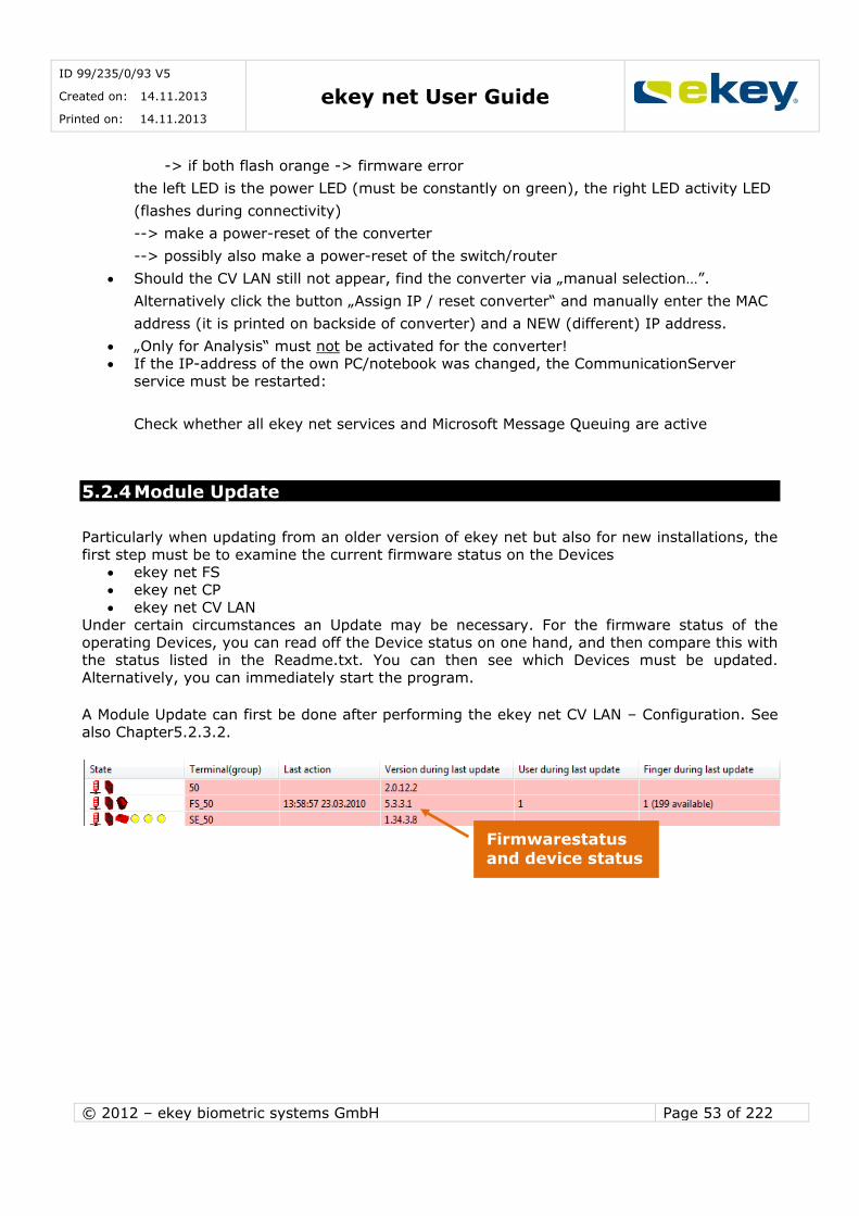
ID 99/235/0/93 V5
Created on: 14.11.2013
Printed on: 14.11.2013 ekey net User Guide
© 2012 – ekey biometric systems GmbH Page 53 of 222
-> if both flash orange -> firmware error
the left LED is the power LED (must be constantly on green), the right LED activity LED
(flashes during connectivity)
--> make a power-reset of the converter
--> possibly also make a power-reset of the switch/router
Should the CV LAN still not appear, find the converter via „manual selection…”.
Alternatively click the button „Assign IP / reset converter“ and manually enter the MAC
address (it is printed on backside of converter) and a NEW (different) IP address.
„Only for Analysis“ must not be activated for the converter! If the IP-address of the own PC/notebook was changed, the CommunicationServer
service must be restarted:
Check whether all ekey net services and Microsoft Message Queuing are active
5.2.4 Module Update
Particularly when updating from an older version of ekey net but also for new installations, the
first step must be to examine the current firmware status on the Devices ekey net FS
ekey net CP
ekey net CV LAN Under certain circumstances an Update may be necessary. For the firmware status of the
operating Devices, you can read off the Device status on one hand, and then compare this with the status listed in the Readme.txt. You can then see which Devices must be updated.
Alternatively, you can immediately start the program.
A Module Update can first be done after performing the ekey net CV LAN – Configuration. See
also Chapter5.2.3.2.
Firmwarestatus and device status

ID 99/235/0/93 V5
Created on: 14.11.2013
Printed on: 14.11.2013 ekey net User Guide
© 2012 – ekey biometric systems GmbH Page 54 of 222
Before a Module Update, make sure the System managed services ekey Service
Guard and ekey net Terminal Server are terminated (stopped)! Otherwise ekey Module Update will not work.
In the status window you will see the latest program versions listed. In this example: Update for 4.1.4.27 (Finger Scanner)
Update for 5.3.3.1 (Finger Scanner) Update for 1.34.3.8 (Control Panel)
Now begin by checking the settings
Normally, the values “Output” and “Baud rate” are already set and locked. If you see
something different to this, change it to LAN, 230400.
Now enter the IP Address and the Converter Port (always “1”) of the first ekey Converter LAN
and click on
So that you can have a connection with ekey net CV LAN, networking must be
accessible to the Program Module Update on the PC, i.e. it must lie in the same
network!
Module Update now lists all Devices connected with this ekey net CV LAN.
Status window
Device selection
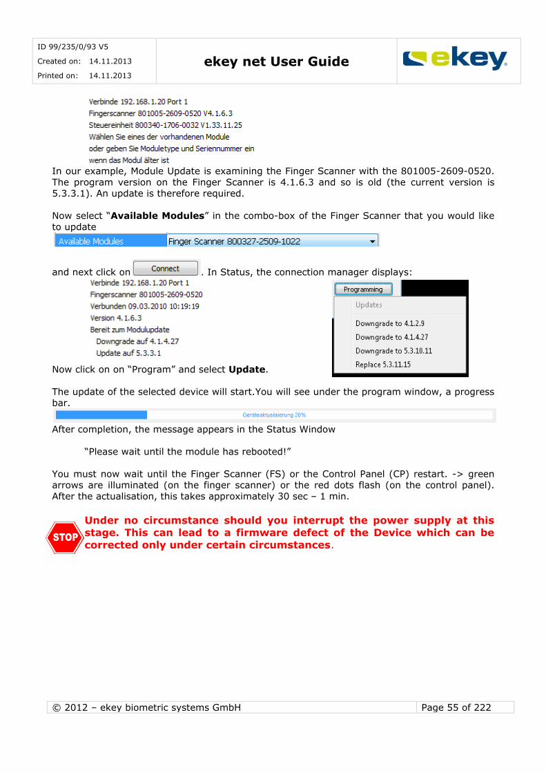
ID 99/235/0/93 V5
Created on: 14.11.2013
Printed on: 14.11.2013 ekey net User Guide
© 2012 – ekey biometric systems GmbH Page 55 of 222
In our example, Module Update is examining the Finger Scanner with the 801005-2609-0520.
The program version on the Finger Scanner is 4.1.6.3 and so is old (the current version is 5.3.3.1). An update is therefore required.
Now select “Available Modules” in the combo-box of the Finger Scanner that you would like
to update
and next click on . In Status, the connection manager displays:
Now click on on “Program” and select Update.
The update of the selected device will start.You will see under the program window, a progress
bar.
After completion, the message appears in the Status Window
“Please wait until the module has rebooted!”
You must now wait until the Finger Scanner (FS) or the Control Panel (CP) restart. -> green arrows are illuminated (on the finger scanner) or the red dots flash (on the control panel).
After the actualisation, this takes approximately 30 sec – 1 min.
Under no circumstance should you interrupt the power supply at this
stage. This can lead to a firmware defect of the Device which can be
corrected only under certain circumstances.
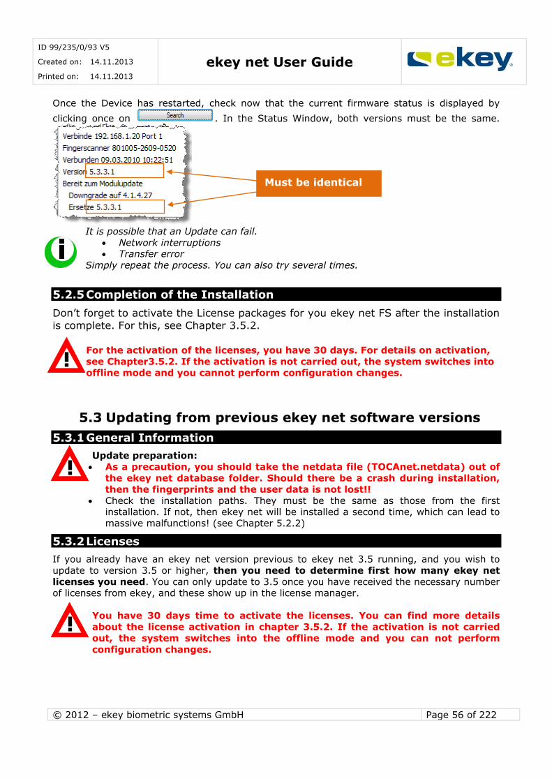
ID 99/235/0/93 V5
Created on: 14.11.2013
Printed on: 14.11.2013 ekey net User Guide
© 2012 – ekey biometric systems GmbH Page 56 of 222
Once the Device has restarted, check now that the current firmware status is displayed by
clicking once on . In the Status Window, both versions must be the same.
It is possible that an Update can fail.
Network interruptions Transfer error
Simply repeat the process. You can also try several times.
5.2.5 Completion of the Installation
Don’t forget to activate the License packages for you ekey net FS after the installation
is complete. For this, see Chapter 3.5.2.
For the activation of the licenses, you have 30 days. For details on activation,
see Chapter3.5.2. If the activation is not carried out, the system switches into offline mode and you cannot perform configuration changes.
5.3 Updating from previous ekey net software versions
5.3.1 General Information
Update preparation:
As a precaution, you should take the netdata file (TOCAnet.netdata) out of
the ekey net database folder. Should there be a crash during installation, then the fingerprints and the user data is not lost!!
Check the installation paths. They must be the same as those from the first installation. If not, then ekey net will be installed a second time, which can lead to
massive malfunctions! (see Chapter 5.2.2)
5.3.2 Licenses
If you already have an ekey net version previous to ekey net 3.5 running, and you wish to
update to version 3.5 or higher, then you need to determine first how many ekey net
licenses you need. You can only update to 3.5 once you have received the necessary number of licenses from ekey, and these show up in the license manager.
You have 30 days time to activate the licenses. You can find more details
about the license activation in chapter 3.5.2. If the activation is not carried out, the system switches into the offline mode and you can not perform
configuration changes.
Must be identical
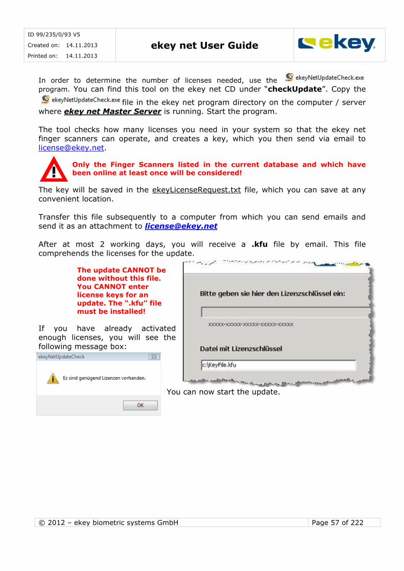
ID 99/235/0/93 V5
Created on: 14.11.2013
Printed on: 14.11.2013 ekey net User Guide
© 2012 – ekey biometric systems GmbH Page 57 of 222
In order to determine the number of licenses needed, use the
program. You can find this tool on the ekey net CD under “checkUpdate”. Copy the
file in the ekey net program directory on the computer / server
where ekey net Master Server is running. Start the program.
The tool checks how many licenses you need in your system so that the ekey net
finger scanners can operate, and creates a key, which you then send via email to
Only the Finger Scanners listed in the current database and which have
been online at least once will be considered!
The key will be saved in the ekeyLicenseRequest.txt file, which you can save at any
convenient location.
Transfer this file subsequently to a computer from which you can send emails and
send it as an attachment to [email protected]
After at most 2 working days, you will receive a .kfu file by email. This file comprehends the licenses for the update.
The update CANNOT be done without this file.
You CANNOT enter license keys for an
update. The “.kfu” file
must be installed!
If you have already activated enough licenses, you will see the
following message box:
You can now start the update.
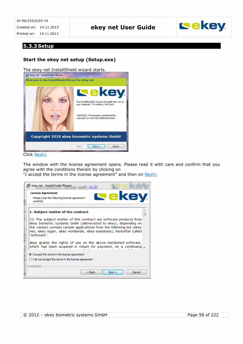
ID 99/235/0/93 V5
Created on: 14.11.2013
Printed on: 14.11.2013 ekey net User Guide
© 2012 – ekey biometric systems GmbH Page 58 of 222
5.3.3 Setup
Start the ekey net setup (Setup.exe) The ekey net InstallShield wizard starts.
Click Next>
The window with the license agreement opens. Please read it with care and confirm that you
agree with the conditions therein by clicking on “I accept the terms in the license agreement” and then on Next>
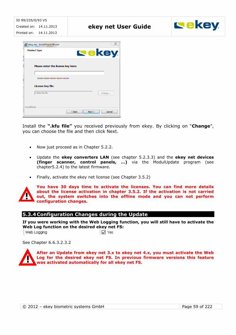
ID 99/235/0/93 V5
Created on: 14.11.2013
Printed on: 14.11.2013 ekey net User Guide
© 2012 – ekey biometric systems GmbH Page 59 of 222
Install the “.kfu file” you received previously from ekey. By clicking on “Change”,
you can choose the file and then click Next.
Now just proceed as in Chapter 5.2.2.
Update the ekey converters LAN (see chapter 5.2.3.3) and the ekey net devices
(finger scanner, control panels, …) via the ModulUpdate program (see chapter5.2.4) to the latest firmware.
Finally, activate the ekey net license (see Chapter 3.5.2)
You have 30 days time to activate the licenses. You can find more details about the license activation in chapter 3.5.2. If the activation is not carried
out, the system switches into the offline mode and you can not perform configuration changes.
5.3.4 Configuration Changes during the Update
If you were working with the Web Logging function, you will still have to activate the Web Log function on the desired ekey net FS:
See Chapter 6.6.3.2.3.2
After an Update from ekey net 3.x to ekey net 4.x, you must activate the Web Log for the desired ekey net FS. In previous firmware versions this feature
was activated automatically for all ekey net FS.
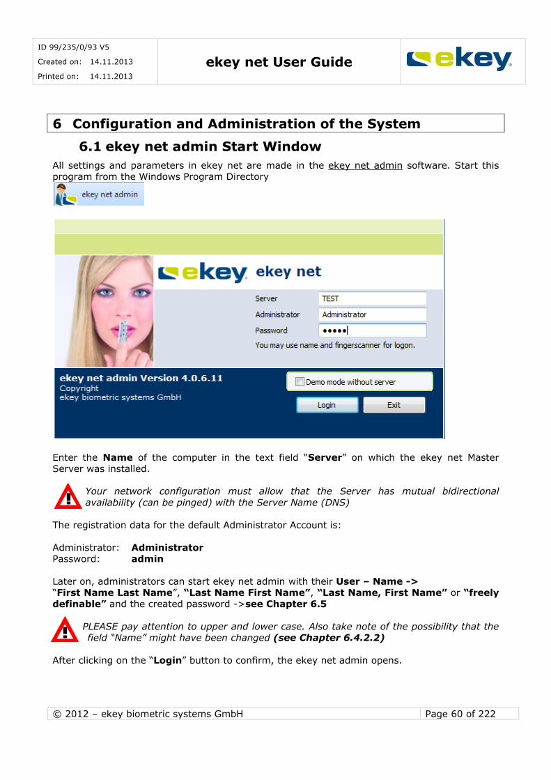
ID 99/235/0/93 V5
Created on: 14.11.2013
Printed on: 14.11.2013 ekey net User Guide
© 2012 – ekey biometric systems GmbH Page 60 of 222
6 Configuration and Administration of the System
6.1 ekey net admin Start Window
All settings and parameters in ekey net are made in the ekey net admin software. Start this program from the Windows Program Directory
Enter the Name of the computer in the text field “Server” on which the ekey net Master Server was installed.
Your network configuration must allow that the Server has mutual bidirectional
availability (can be pinged) with the Server Name (DNS)
The registration data for the default Administrator Account is:
Administrator: Administrator
Password: admin
Later on, administrators can start ekey net admin with their User – Name -> “First Name Last Name”, “Last Name First Name”, “Last Name, First Name” or “freely
definable” and the created password ->see Chapter 6.5
PLEASE pay attention to upper and lower case. Also take note of the possibility that the field “Name” might have been changed (see Chapter 6.4.2.2)
After clicking on the “Login” button to confirm, the ekey net admin opens.

ID 99/235/0/93 V5
Created on: 14.11.2013
Printed on: 14.11.2013 ekey net User Guide
© 2012 – ekey biometric systems GmbH Page 61 of 222
LIGHT
COM BUSINESS
e
After its start, the ekey net admin checks the activated license numbers against the numbers
of the registered Finger Scanners in ekey net. If there are too few activated licenses, the above message box will be displayed. To continue further, activate the outstanding licenses.
If you continue operating ekey net after this message without correcting it,
the ekey net FSs without licenses will not work properly. It cannot be said which scanners will be affected exactly!
Starting image of ekey net admin
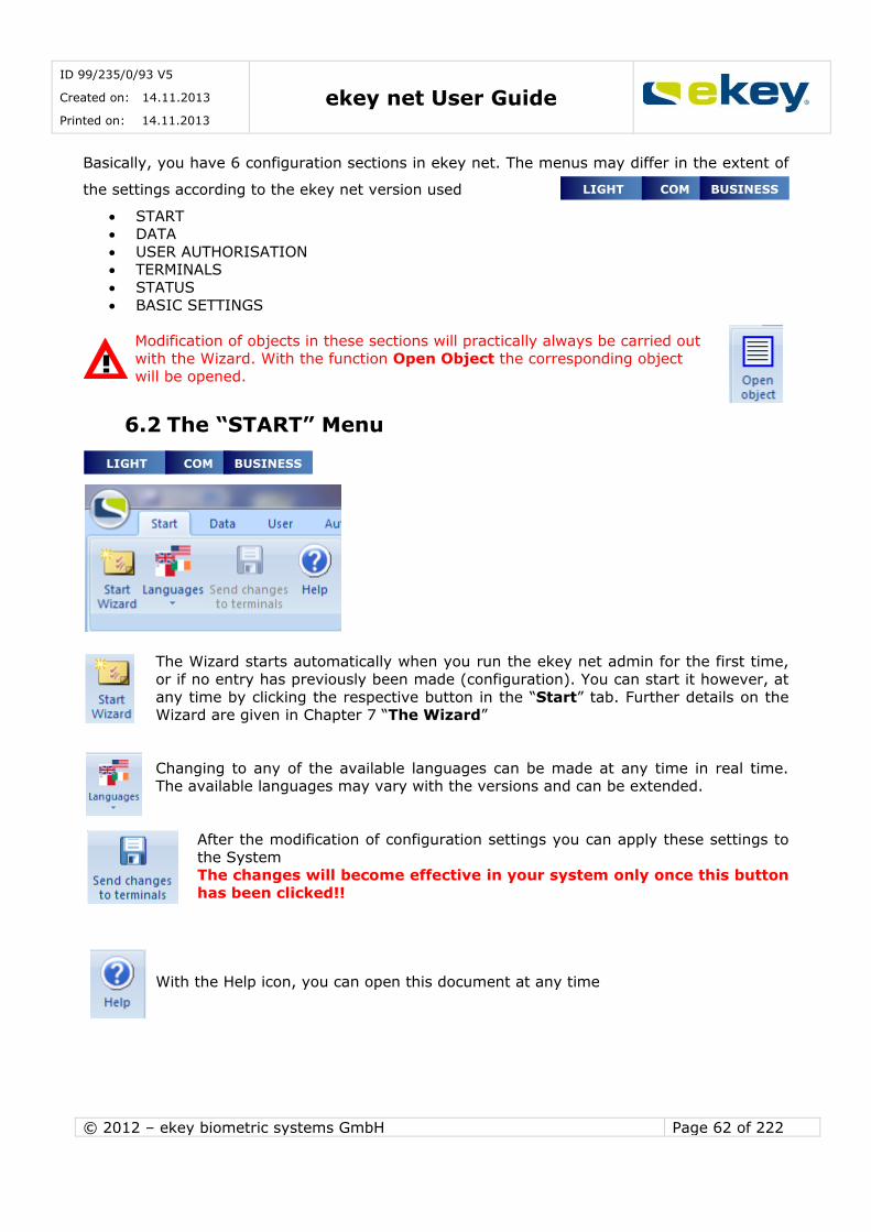
ID 99/235/0/93 V5
Created on: 14.11.2013
Printed on: 14.11.2013 ekey net User Guide
© 2012 – ekey biometric systems GmbH Page 62 of 222
LIGHT COM BUSINESS
e
Basically, you have 6 configuration sections in ekey net. The menus may differ in the extent of
the settings according to the ekey net version used
START DATA
USER AUTHORISATION TERMINALS
STATUS
BASIC SETTINGS
Modification of objects in these sections will practically always be carried out with the Wizard. With the function Open Object the corresponding object
will be opened.
6.2 The “START” Menu
The Wizard starts automatically when you run the ekey net admin for the first time,
or if no entry has previously been made (configuration). You can start it however, at
any time by clicking the respective button in the “Start” tab. Further details on the Wizard are given in Chapter 7 “The Wizard”
Changing to any of the available languages can be made at any time in real time. The available languages may vary with the versions and can be extended.
After the modification of configuration settings you can apply these settings to
the System The changes will become effective in your system only once this button
has been clicked!!
With the Help icon, you can open this document at any time
LIGHT COM BUSINESS
e
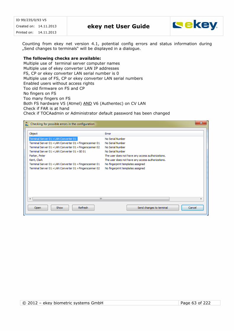
ID 99/235/0/93 V5
Created on: 14.11.2013
Printed on: 14.11.2013 ekey net User Guide
© 2012 – ekey biometric systems GmbH Page 63 of 222
Counting from ekey net version 4.1, potential config errors and status information during
„Send changes to terminals“ will be displayed in a dialogue.
The following checks are available:
Multiple use of terminal server computer names
Multiple use of ekey converter LAN IP addresses
FS, CP or ekey converter LAN serial number is 0
Multiple use of FS, CP or ekey converter LAN serial numbers
Enabled users without access rights
Too old firmware on FS and CP
No fingers on FS
Too many fingers on FS
Both FS hardware V5 (Atmel) AND V6 (Authentec) on CV LAN
Check if FAR is at hand Check if TOCAadmin or Administrator default password has been changed
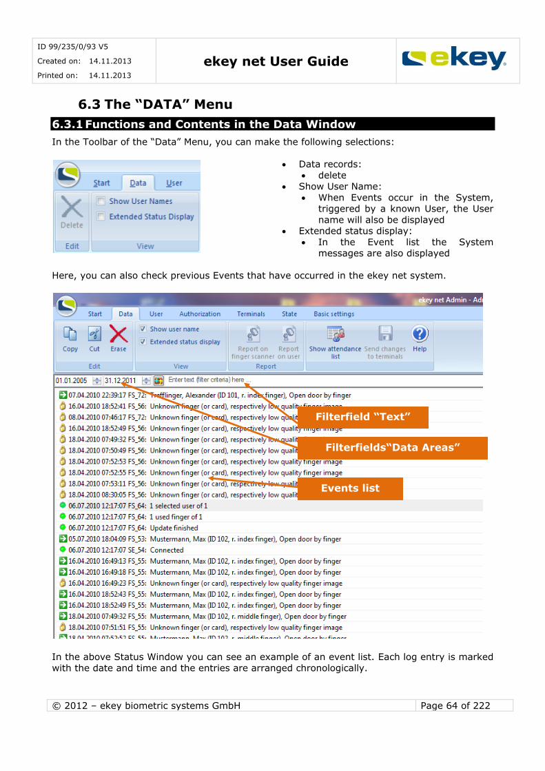
ID 99/235/0/93 V5
Created on: 14.11.2013
Printed on: 14.11.2013 ekey net User Guide
© 2012 – ekey biometric systems GmbH Page 64 of 222
6.3 The “DATA” Menu
6.3.1 Functions and Contents in the Data Window
In the Toolbar of the “Data” Menu, you can make the following selections:
Data records: delete
Show User Name:
When Events occur in the System, triggered by a known User, the User
name will also be displayed Extended status display:
In the Event list the System messages are also displayed
Here, you can also check previous Events that have occurred in the ekey net system.
In the above Status Window you can see an example of an event list. Each log entry is marked
with the date and time and the entries are arranged chronologically.
Events list
Filterfield “Text”
Filterfields“Data Areas”

ID 99/235/0/93 V5
Created on: 14.11.2013
Printed on: 14.11.2013 ekey net User Guide
© 2012 – ekey biometric systems GmbH Page 65 of 222
With “Delete” you can delete the whole list in ekey net.
Show Attendance List:
This will open the attendance list – see details in Chapter10
Send changes to the Terminal: Possibility of updating the System
Help:
To open this User Guide as a PDF
6.3.2 Reports on User activities or Finger Scanner activities
This function is active only when “Reporting” in “Basic Settings -> Records” is activated and configured properly. See Chapter 8.1.1.1
From ekey net Version 4 the following reports are possible: To display on screen
To export to HTML -> and then possible to print from the
WEB Browser To export to a CSV file
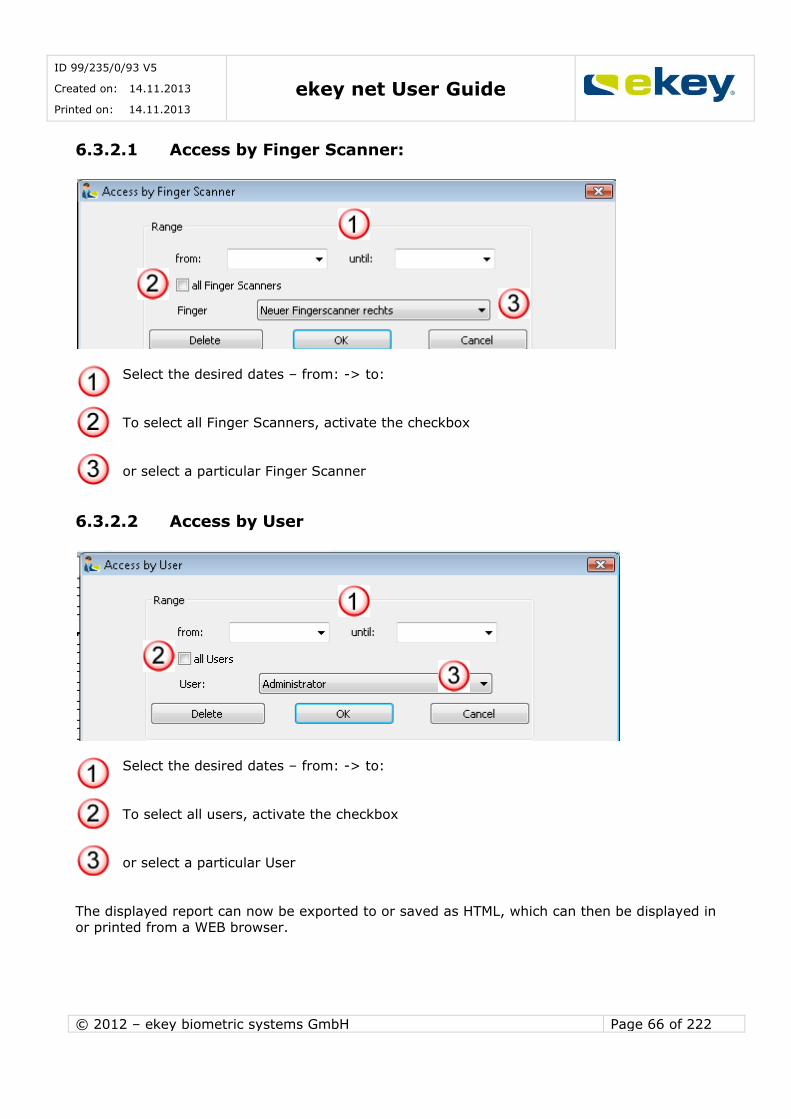
ID 99/235/0/93 V5
Created on: 14.11.2013
Printed on: 14.11.2013 ekey net User Guide
© 2012 – ekey biometric systems GmbH Page 66 of 222
6.3.2.1 Access by Finger Scanner:
Select the desired dates – from: -> to:
To select all Finger Scanners, activate the checkbox
or select a particular Finger Scanner
6.3.2.2 Access by User
Select the desired dates – from: -> to:
To select all users, activate the checkbox
or select a particular User
The displayed report can now be exported to or saved as HTML, which can then be displayed in or printed from a WEB browser.

ID 99/235/0/93 V5
Created on: 14.11.2013
Printed on: 14.11.2013 ekey net User Guide
© 2012 – ekey biometric systems GmbH Page 67 of 222
6.3.3 Data Window in Device Status
To get to Device Status, click on the Status menu.
Click on the specific Device or Device Group, so you can see only the log messages of the
allocated Device / Device Group. Otherwise “Display User Name” and “Extended Status Display” are available in the pop-up menu as described in Chapter 6.3.1
6.3.4 FAR Check
Counting from ekey net version 4.1, it is possible to run an FAR check. FAR=False Acceptance Rate.
The system checks if 2 users have the same fingers. This may happen if one person has been enrolled twice, or if 2 people´s fingers have been enrolled wrong (e.g. just the fingertip).
Right click on FAR check. If there is a problem, then an information dialogue will be displayed.
You can then see which two users/fingers are the same in the system and make the necessary
corrections.
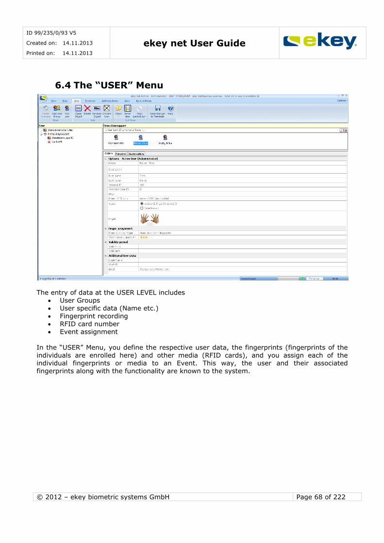
ID 99/235/0/93 V5
Created on: 14.11.2013
Printed on: 14.11.2013 ekey net User Guide
© 2012 – ekey biometric systems GmbH Page 68 of 222
6.4 The “USER” Menu
The entry of data at the USER LEVEL includes
User Groups User specific data (Name etc.)
Fingerprint recording
RFID card number Event assignment
In the “USER” Menu, you define the respective user data, the fingerprints (fingerprints of the
individuals are enrolled here) and other media (RFID cards), and you assign each of the individual fingerprints or media to an Event. This way, the user and their associated
fingerprints along with the functionality are known to the system.

ID 99/235/0/93 V5
Created on: 14.11.2013
Printed on: 14.11.2013 ekey net User Guide
© 2012 – ekey biometric systems GmbH Page 69 of 222
6.4.1 Schematic Procedure for Adding a User
At this level it is NOT known, on which Control Panel the Action is to be executed
If any authorisations to execute the Action are set at all (location / time /
calendar set authorisation). Therefore no Action execution will follow just yet, without the appropriate
configuration of the TERMINAL and AUTHORISATION LEVEL.
6.4.2 Entering the Parameter and Data
6.4.2.1 Companies and User Groups
In ekey net you can create companies and user groups for
a better system overview of your users
a simple and clear authorisation structure. Companies and user groups are added in the menu tab “User”
Companies are separate organisational units. A user from a Company can generally only
receive permissions within the Company he/she is belonging to. However, permissions may vary between user groups within a company.
User is recorded (Name, Position etc.)
Note on the workings of this allocation:
A triggered Event in turn leads to an Action. An Action, for example, switches
a relay output on the ekey net CP. In ekey net Admin,
one Event can be allocated to one (two) Action(s).
The Action(s) are then carried out by the respective Control Panel (e.g.
switching Relay Output 1 for 3 seconds).
An individual Fingerprint is allocated to an Event
One Finger -> One Event
the Finger and/or media (RFID card) of the user is enrolled.
Send changes to Terminal. Only from now on the changes will become effective in your system!!

ID 99/235/0/93 V5
Created on: 14.11.2013
Printed on: 14.11.2013 ekey net User Guide
© 2012 – ekey biometric systems GmbH Page 70 of 222
Before you start the user configuration, consider exactly which users will have the same rights (same Time zone access), and put these together into a group. The clarity of the
System, simplification of maintenance, and ultimately the reliability will increase enormously. Doing this, you will save time and money!
By clicking on the menu button “Add Company” you determine the top levels.
In the ekey net Wizard you define the “Name” of the Company. Further additional information
can be given under “Description”.
By clicking on the button “Create User Group” you are now setting the User Groups.
User Groups serve to create convenience of the system and to simplify management. It’s up to
you how you build the groups. You can also create more groups here (virtually unlimited).
We recommend users with the same access rights being grouped together (time of access to the Terminal). You can then manage entire user groupsand their corresponding access rights
directly on the terminals (see Chapter6.5), rather than having to deal with individual users rights.
In the above example, the users were grouped by departments. With the ekey net Wizard you
then define the “Name” of the user group and you can also add a “Description” here.
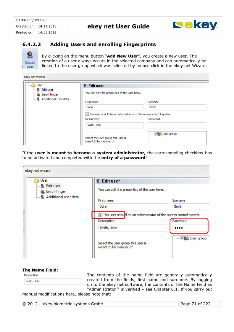
ID 99/235/0/93 V5
Created on: 14.11.2013
Printed on: 14.11.2013 ekey net User Guide
© 2012 – ekey biometric systems GmbH Page 71 of 222
6.4.2.2 Adding Users and enrolling Fingerprints
By clicking on the menu button “Add New User”, you create a new user. The
creation of a user always occurs in the selected company and can automatically be linked to the user group which was selected by mouse click in the ekey net Wizard.
If the user is meant to become a system administrator, the corresponding checkbox has to be activated and completed with the entry of a password!
The Name Field:
The contents of the name field are generally automatically created from the fields, first name and surname. By logging
on to the ekey net software, the contents of the Name Field as “Administrator “ is verified – see Chapter 6.1. If you carry out
manual modifications here, please note that:
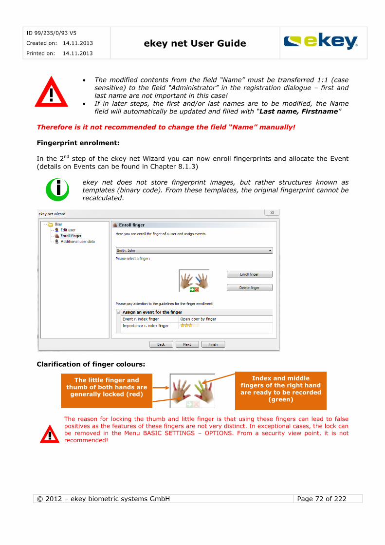
ID 99/235/0/93 V5
Created on: 14.11.2013
Printed on: 14.11.2013 ekey net User Guide
© 2012 – ekey biometric systems GmbH Page 72 of 222
The modified contents from the field “Name” must be transferred 1:1 (case sensitive) to the field “Administrator” in the registration dialogue – first and
last name are not important in this case! If in later steps, the first and/or last names are to be modified, the Name
field will automatically be updated and filled with “Last name, Firstname”
Therefore is it not recommended to change the field “Name” manually!
Fingerprint enrolment:
In the 2nd step of the ekey net Wizard you can now enroll fingerprints and allocate the Event
(details on Events can be found in Chapter 8.1.3)
ekey net does not store fingerprint images, but rather structures known as templates (binary code). From these templates, the original fingerprint cannot be
recalculated.
Clarification of finger colours:
The reason for locking the thumb and little finger is that using these fingers can lead to false positives as the features of these fingers are not very distinct. In exceptional cases, the lock can be removed in the Menu BASIC SETTINGS – OPTIONS. From a security view point, it is not
recommended!
The little finger and thumb of both hands are generally locked (red)
Index and middle fingers of the right hand
are ready to be recorded (green)
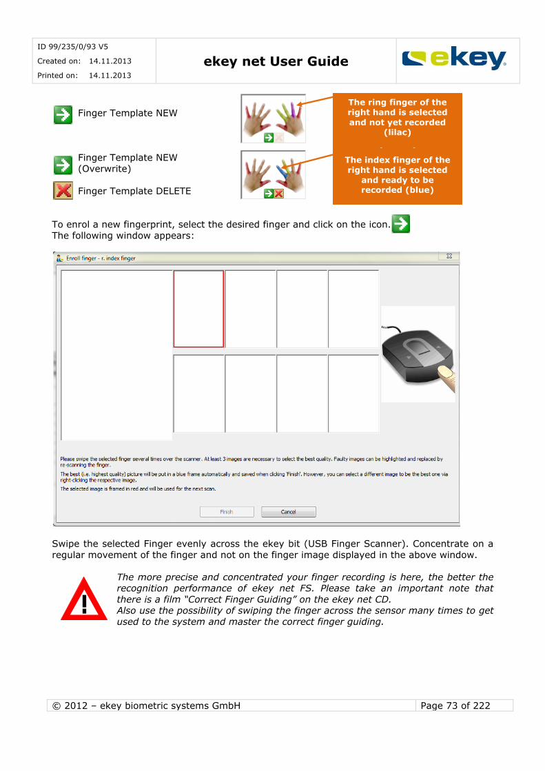
ID 99/235/0/93 V5
Created on: 14.11.2013
Printed on: 14.11.2013 ekey net User Guide
© 2012 – ekey biometric systems GmbH Page 73 of 222
Finger Template NEW
Finger Template NEW (Overwrite)
Finger Template DELETE
To enrol a new fingerprint, select the desired finger and click on the icon.
The following window appears:
Swipe the selected Finger evenly across the ekey bit (USB Finger Scanner). Concentrate on a
regular movement of the finger and not on the finger image displayed in the above window.
The more precise and concentrated your finger recording is here, the better the recognition performance of ekey net FS. Please take an important note that
there is a film “Correct Finger Guiding” on the ekey net CD. Also use the possibility of swiping the finger across the sensor many times to get
used to the system and master the correct finger guiding.
Ringfinger der rechten Hand ist ausgewählt
und noch nicht erfasst (violett)
The index finger of the
right hand is selected and ready to be recorded (blue)
The ring finger of the right hand is selected
and not yet recorded (lilac)

ID 99/235/0/93 V5
Created on: 14.11.2013
Printed on: 14.11.2013 ekey net User Guide
© 2012 – ekey biometric systems GmbH Page 74 of 222
At least 3 finger scans must be taken. The analysis of the finger images can be seen directly
on the bar below the images:
… Finger image is correct and OK for use in ekey net
… Finger image is just sufficient for use in ekey net. If you don’t get a green bar, you
can still work with this finger image.
… Finger image has very limited to no use.
The number within the bar shows further quality information (= Score). However, you don’t
need to try to achieve the highest number possible in this bar; it is enough when the bar is
green. After scanning the same fingerprint several times, the system highlights the best template
which will then be saved and distributed to the Finger Scanners. You can see which finger image is recommended because it is framed in blue.
We recommend to accept this identified template and to finish the fingerprint enrolment by clicking „Finish”.
It is possible that you scanned your finger with ekey bit, but no fingerprint image
appeared. This is normal.
ekey net cut outs completely corrupted images immediately and shows only the “Bad Quality – Please try again” message. If you have difficulties enrolling the fingerprint,
please refer to the movie “Correct Finger Guiding” on the enclosed CD.
Event Allocation: Next you must also allocate the recorded fingerprints to an appropriate Event, so that an
Action can be executed in the System. The assignment is made at this point. You can allocate each individual finger to a different Event, where you have the possibility of setting 10 fingers
to 10 different Events in the System.
Information bar
on the quality of
the fingerprint image.
Blue frame. ekey net
suggests using this fingerprint.

ID 99/235/0/93 V5
Created on: 14.11.2013
Printed on: 14.11.2013 ekey net User Guide
© 2012 – ekey biometric systems GmbH Page 75 of 222
In the example here, the “Right Index Finger” is assigned to “Open Door with Finger”. For the
function and workings of Events, see Chapter 8.1.3.
Another special function is available via the “Importance” (ranking) of the fingerprint. Here you have the possibility to define faster recognition on the fingerprint scanner and so enabling
faster activation for certain users (e.g. Management). This arises from users with higher
priorities having Star Ranking and so the reference templates of these users are checked first. New users will have 3 stars allocated automatically. You can increase or decrease their
importance by a mouse click.
If you give all users the same importance, this will lead to ekey net making an intelligent examination of the reference templates. Depending on how often the system
is used (fingerprint is scanned), the examination defines the ranking of the reference templates in the queue. User who uses the system more often will have faster access.
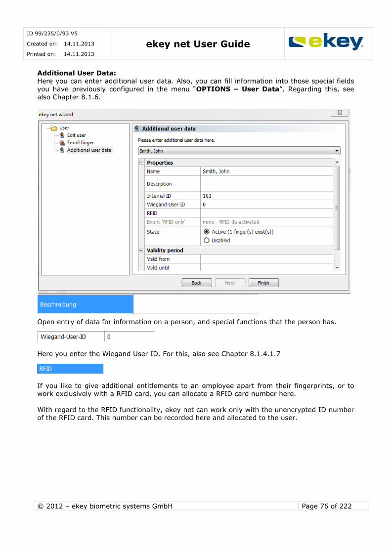
ID 99/235/0/93 V5
Created on: 14.11.2013
Printed on: 14.11.2013 ekey net User Guide
© 2012 – ekey biometric systems GmbH Page 76 of 222
Additional User Data:
Here you can enter additional user data. Also, you can fill information into those special fields you have previously configured in the menu “OPTIONS – User Data”. Regarding this, see
also Chapter 8.1.6.
Description:
Open entry of data for information on a person, and special functions that the person has.
Wiegand-Benutzer-ID
Here you enter the Wiegand User ID. For this, also see Chapter 8.1.4.1.7
RFID:
If you like to give additional entitlements to an employee apart from their fingerprints, or to work exclusively with a RFID card, you can allocate a RFID card number here.
With regard to the RFID functionality, ekey net can work only with the unencrypted ID number
of the RFID card. This number can be recorded here and allocated to the user.
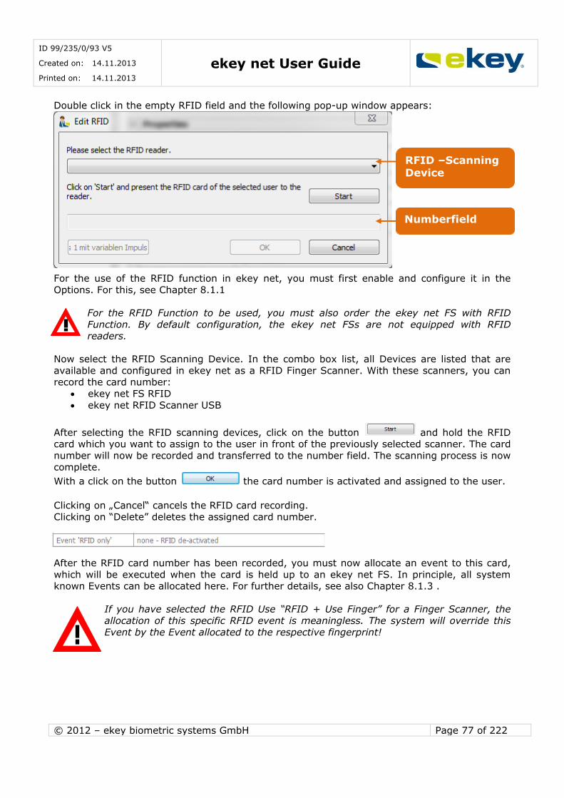
ID 99/235/0/93 V5
Created on: 14.11.2013
Printed on: 14.11.2013 ekey net User Guide
© 2012 – ekey biometric systems GmbH Page 77 of 222
Double click in the empty RFID field and the following pop-up window appears:
For the use of the RFID function in ekey net, you must first enable and configure it in the
Options. For this, see Chapter 8.1.1
For the RFID Function to be used, you must also order the ekey net FS with RFID
Function. By default configuration, the ekey net FSs are not equipped with RFID readers.
Now select the RFID Scanning Device. In the combo box list, all Devices are listed that are
available and configured in ekey net as a RFID Finger Scanner. With these scanners, you can record the card number:
ekey net FS RFID
ekey net RFID Scanner USB
After selecting the RFID scanning devices, click on the button and hold the RFID card which you want to assign to the user in front of the previously selected scanner. The card
number will now be recorded and transferred to the number field. The scanning process is now
complete.
With a click on the button the card number is activated and assigned to the user.
Clicking on „Cancel“ cancels the RFID card recording.
Clicking on “Delete” deletes the assigned card number.
Event “RFID only”
After the RFID card number has been recorded, you must now allocate an event to this card,
which will be executed when the card is held up to an ekey net FS. In principle, all system known Events can be allocated here. For further details, see also Chapter 8.1.3 .
If you have selected the RFID Use “RFID + Use Finger” for a Finger Scanner, the
allocation of this specific RFID event is meaningless. The system will override this
Event by the Event allocated to the respective fingerprint!
Numberfield
RFID –Scanning Device
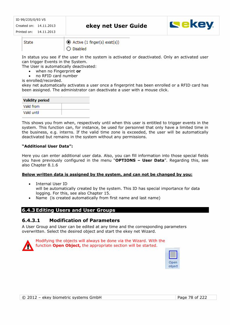
ID 99/235/0/93 V5
Created on: 14.11.2013
Printed on: 14.11.2013 ekey net User Guide
© 2012 – ekey biometric systems GmbH Page 78 of 222
Sate:
In status you see if the user in the system is activated or deactivated. Only an activated user can trigger Events in the System.
The User is automatically deactivated: when no Fingerprint or
no RFID card number
is enrolled/recorded. ekey net automatically activates a user once a fingerprint has been enrolled or a RFID card has
been assigned. The administrator can deactivate a user with a mouse click.
Validity period:
This shows you from when, respectively until when this user is entitled to trigger events in the system. This function can, for instance, be used for personnel that only have a limited time in
the business, e.g. interns. If the valid time zone is exceeded, the user will be automatically deactivated but remains in the system without any permissions.
“Additional User Data”:
Here you can enter additional user data. Also, you can fill information into those special fields
you have previously configured in the menu “OPTIONS – User Data”. Regarding this, see
also Chapter 8.1.6
Below written data is assigned by the system, and can not be changed by you:
Internal User ID will be automatically created by the system. This ID has special importance for data
logging. For this, see also Chapter 15. Name (is created automatically from first name and last name)
6.4.3 Editing Users and User Groups
6.4.3.1 Modification of Parameters
A User Group and User can be edited at any time and the corresponding parameters overwritten. Select the desired object and start the ekey net Wizard.
Modifying the objects will always be done via the Wizard. With the
function Open Object, the appropriate section will be started.
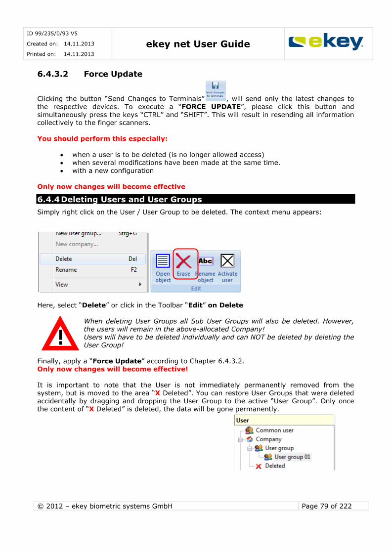
ID 99/235/0/93 V5
Created on: 14.11.2013
Printed on: 14.11.2013 ekey net User Guide
© 2012 – ekey biometric systems GmbH Page 79 of 222
6.4.3.2 Force Update
Clicking the button “Send Changes to Terminals” , will send only the latest changes to
the respective devices. To execute a “FORCE UPDATE”, please click this button and
simultaneously press the keys “CTRL” and “SHIFT”. This will result in resending all information collectively to the finger scanners.
You should perform this especially:
when a user is to be deleted (is no longer allowed access) when several modifications have been made at the same time.
with a new configuration
Only now changes will become effective
6.4.4 Deleting Users and User Groups
Simply right click on the User / User Group to be deleted. The context menu appears:
Here, select “Delete” or click in the Toolbar “Edit” on Delete
When deleting User Groups all Sub User Groups will also be deleted. However, the users will remain in the above-allocated Company!
Users will have to be deleted individually and can NOT be deleted by deleting the User Group!
Finally, apply a “Force Update” according to Chapter 6.4.3.2.
Only now changes will become effective!
It is important to note that the User is not immediately permanently removed from the
system, but is moved to the area “X Deleted”. You can restore User Groups that were deleted accidentally by dragging and dropping the User Group to the active “User Group”. Only once
the content of “X Deleted” is deleted, the data will be gone permanently.

ID 99/235/0/93 V5
Created on: 14.11.2013
Printed on: 14.11.2013 ekey net User Guide
© 2012 – ekey biometric systems GmbH Page 80 of 222
6.4.5 User Export and Import
You can export data from Users and User Groups – including the fingerprint templates – from ekey net and import them into another system. This is very advantageous for example, for a
company that is relocating, so that the employee fingerprints do not have to be rescanned.
6.4.5.1 User Export
For an Export, select the User / User Group to be exported in the User Explorer.
Here, as an example, the User “John Smith”
from User Group is to be exported
Click on the ekey Symbol in the upper left hand corner (menu bar) and select “Export”.
For the User Groups (internal Format), the system will
create an internal file,
at your desired location with a definable file name
This file contains all User data including Fingerprint templates though without authorisation
structure, which can be re-imported at any time to another or the same ekey net installation.

ID 99/235/0/93 V5
Created on: 14.11.2013
Printed on: 14.11.2013 ekey net User Guide
© 2012 – ekey biometric systems GmbH Page 81 of 222
The Export of a User List will result in an export of User data WITHOUT Fingerprint
templates. Possible Export formats are: .XML Example of an XML Export:
.XLS .CSV
6.4.5.2 User Import
Select the Terminal Groups, in which the User / User Group to be imported, is to be inserted.
Click on the ekey Symbol in the upper left hand corner (menu bar)”.
Now select “Import” and then one of the formats:
User Groups (internal format): Users / User Groups containing also fingerprint templates User List: only data without any Fingerprint templates
This opens the Windows Dialogue to select the appropriate files and after your selection the
data is inserted into the desired area of the User structure.

ID 99/235/0/93 V5
Created on: 14.11.2013
Printed on: 14.11.2013 ekey net User Guide
© 2012 – ekey biometric systems GmbH Page 82 of 222
6.5 The “AUTHORISATIONS” Menu
In the authorisation menu, it shows the allocation of who is entitled to trigger actions, when and where.
Before you begin the actual assigning of permissions, you must define the Time zones
(Chapter 6.6.6) and Calendar (Chapter 6.6.7) for the individual Terminal Groups
6.5.1 Authorisations
Here you define who, when, where has access / can trigger an Event with his / her Fingerprint.
The authorisations are assigned User Related. This means that a specific Time zone assigned to a Terminal will be applicable for all Fingerprints of a certain User.
The presentation of the Authorisation Level:
6.5.1.1 Assignment of Authorisations
To assign an authorisation, proceed as follows:
Terminal Selection: Select the Terminal Groups / Terminal (Finger Scanner) with a mouse click on the User Group /
User that you want to authorise:
The Time zone of the terminal level can now be seen in the authorisation window.
Terminal
Groups
User Groups
Authorisation Window
Time Frame of
the selected Terminal Groups
User of the
selected
User Group Terminal
Groups
Terminalgru
ppe
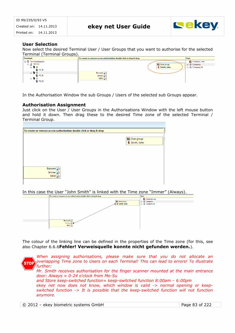
ID 99/235/0/93 V5
Created on: 14.11.2013
Printed on: 14.11.2013 ekey net User Guide
© 2012 – ekey biometric systems GmbH Page 83 of 222
User Selection Now select the desired Terminal User / User Groups that you want to authorise for the selected
Terminal (Terminal Groups).
In the Authorisation Window the sub Groups / Users of the selected sub Groups appear.
Authorisation Assignment Just click on the User / User Groups in the Authorisations Window with the left mouse button and hold it down. Then drag these to the desired Time zone of the selected Terminal /
Terminal Group.
In this case the User “John Smith” is linked with the Time zone “Immer” (Always).
The colour of the linking line can be defined in the properties of the Time zone (for this, see
also Chapter 6.6.6Fehler! Verweisquelle konnte nicht gefunden werden.).
When assigning authorisations, please make sure that you do not allocate an overlapping Time zone to Users on each Terminal! This can lead to errors! To illustrate
further:
Mr. Smith receives authorisation for the finger scanner mounted at the main entrance door: Always = 0-24 o’clock from Mo-Su
and Store keep-switched function= keep-switched function 8:00am – 6:00pm ekey net now does not know, which window is valid -> normal opening or keep-
switched function -> It is possible that the keep-switched function will not function anymore.
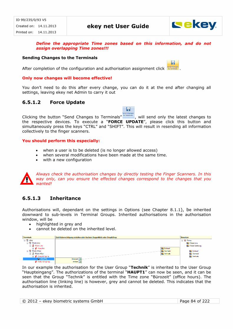
ID 99/235/0/93 V5
Created on: 14.11.2013
Printed on: 14.11.2013 ekey net User Guide
© 2012 – ekey biometric systems GmbH Page 84 of 222
Define the appropriate Time zones based on this information, and do not
assign overlapping Time zones!!!
Sending Changes to the Terminals
After completion of the configuration and authorisation assignment click .
Only now changes will become effective!
You don’t need to do this after every change, you can do it at the end after changing all
settings, leaving ekey net Admin to carry it out
6.5.1.2 Force Update
Clicking the button “Send Changes to Terminals” , will send only the latest changes to
the respective devices. To execute a “FORCE UPDATE”, please click this button and
simultaneously press the keys “CTRL” and “SHIFT”. This will result in resending all information collectively to the finger scanners.
You should perform this especially:
when a user is to be deleted (is no longer allowed access) when several modifications have been made at the same time.
with a new configuration
Always check the authorisation changes by directly testing the Finger Scanners. In this
way only, can you ensure the effected changes correspond to the changes that you wanted!
6.5.1.3 Inheritance
Authorisations will, dependant on the settings in Options (see Chapter 8.1.1), be inherited
downward to sub-levels in Terminal Groups. Inherited authorisations in the authorisation
window, will be highlighted in grey and
cannot be deleted on the inherited level.
In our example the authorisation for the User Group “Technik” is inherited to the User Group
“Haupteingang”. The authorizations of the terminal “HAUPT1” can now be seen, and it can be seen that the Group “Technik” is entitled with the Time zone “Bürozeit” (office hours). The
authorisation line (linking line) is however, grey and cannot be deleted. This indicates that the authorisation is inherited.
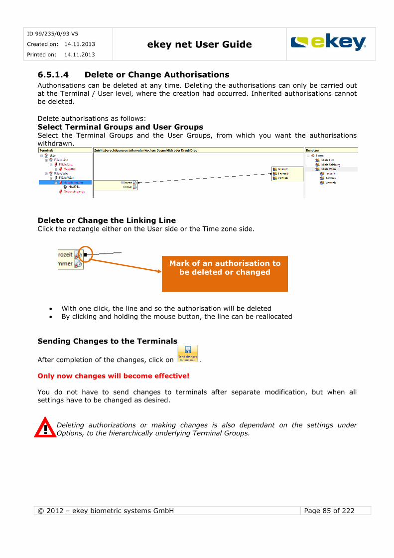
ID 99/235/0/93 V5
Created on: 14.11.2013
Printed on: 14.11.2013 ekey net User Guide
© 2012 – ekey biometric systems GmbH Page 85 of 222
6.5.1.4 Delete or Change Authorisations
Authorisations can be deleted at any time. Deleting the authorisations can only be carried out
at the Terminal / User level, where the creation had occurred. Inherited authorisations cannot be deleted.
Delete authorisations as follows:
Select Terminal Groups and User Groups Select the Terminal Groups and the User Groups, from which you want the authorisations
withdrawn.
Delete or Change the Linking Line Click the rectangle either on the User side or the Time zone side.
With one click, the line and so the authorisation will be deleted By clicking and holding the mouse button, the line can be reallocated
Sending Changes to the Terminals
After completion of the changes, click on .
Only now changes will become effective!
You do not have to send changes to terminals after separate modification, but when all settings have to be changed as desired.
Deleting authorizations or making changes is also dependant on the settings under
Options, to the hierarchically underlying Terminal Groups.
Mark of an authorisation to be deleted or changed
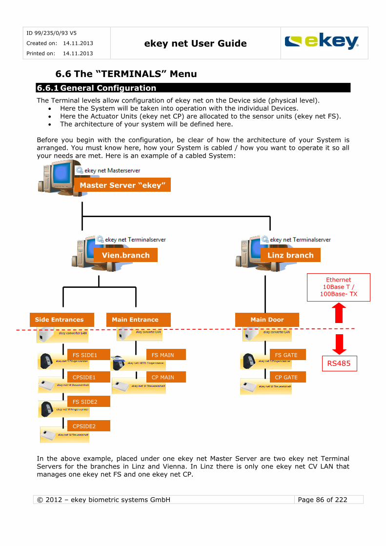
ID 99/235/0/93 V5
Created on: 14.11.2013
Printed on: 14.11.2013 ekey net User Guide
© 2012 – ekey biometric systems GmbH Page 86 of 222
6.6 The “TERMINALS” Menu
6.6.1 General Configuration
The Terminal levels allow configuration of ekey net on the Device side (physical level). Here the System will be taken into operation with the individual Devices.
Here the Actuator Units (ekey net CP) are allocated to the sensor units (ekey net FS). The architecture of your system will be defined here.
Before you begin with the configuration, be clear of how the architecture of your System is arranged. You must know here, how your System is cabled / how you want to operate it so all
your needs are met. Here is an example of a cabled System:
In the above example, placed under one ekey net Master Server are two ekey net Terminal Servers for the branches in Linz and Vienna. In Linz there is only one ekey net CV LAN that
manages one ekey net FS and one ekey net CP.
Master Server “ekey”
Vien.branch Linz branch
Side Entrances Main Entrance Main Door
FS MAIN
CP MAIN
FS SIDE1
CPSIDE1
FS SIDE2
CPSIDE2
FS GATE
CP GATE
RS485
Ethernet 10Base T /
100Base- TX
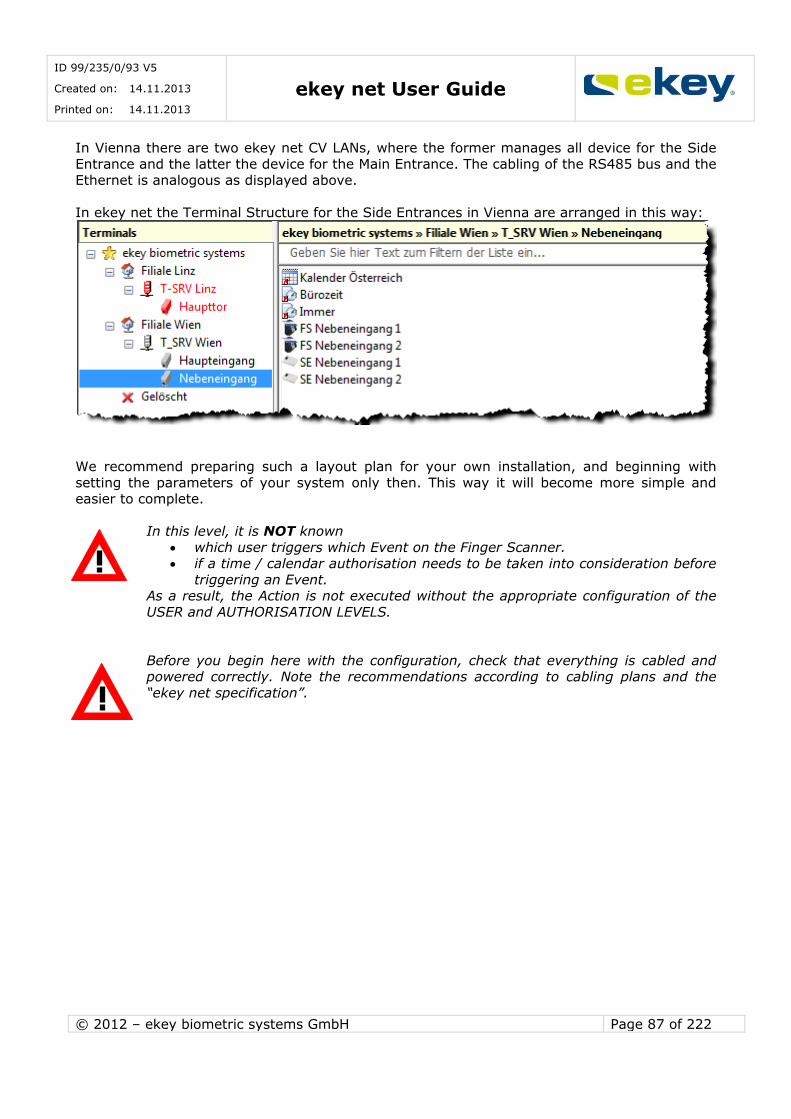
ID 99/235/0/93 V5
Created on: 14.11.2013
Printed on: 14.11.2013 ekey net User Guide
© 2012 – ekey biometric systems GmbH Page 87 of 222
In Vienna there are two ekey net CV LANs, where the former manages all device for the Side
Entrance and the latter the device for the Main Entrance. The cabling of the RS485 bus and the Ethernet is analogous as displayed above.
In ekey net the Terminal Structure for the Side Entrances in Vienna are arranged in this way:
We recommend preparing such a layout plan for your own installation, and beginning with
setting the parameters of your system only then. This way it will become more simple and easier to complete.
In this level, it is NOT known
which user triggers which Event on the Finger Scanner. if a time / calendar authorisation needs to be taken into consideration before
triggering an Event. As a result, the Action is not executed without the appropriate configuration of the
USER and AUTHORISATION LEVELS.
Before you begin here with the configuration, check that everything is cabled and powered correctly. Note the recommendations according to cabling plans and the
“ekey net specification”.
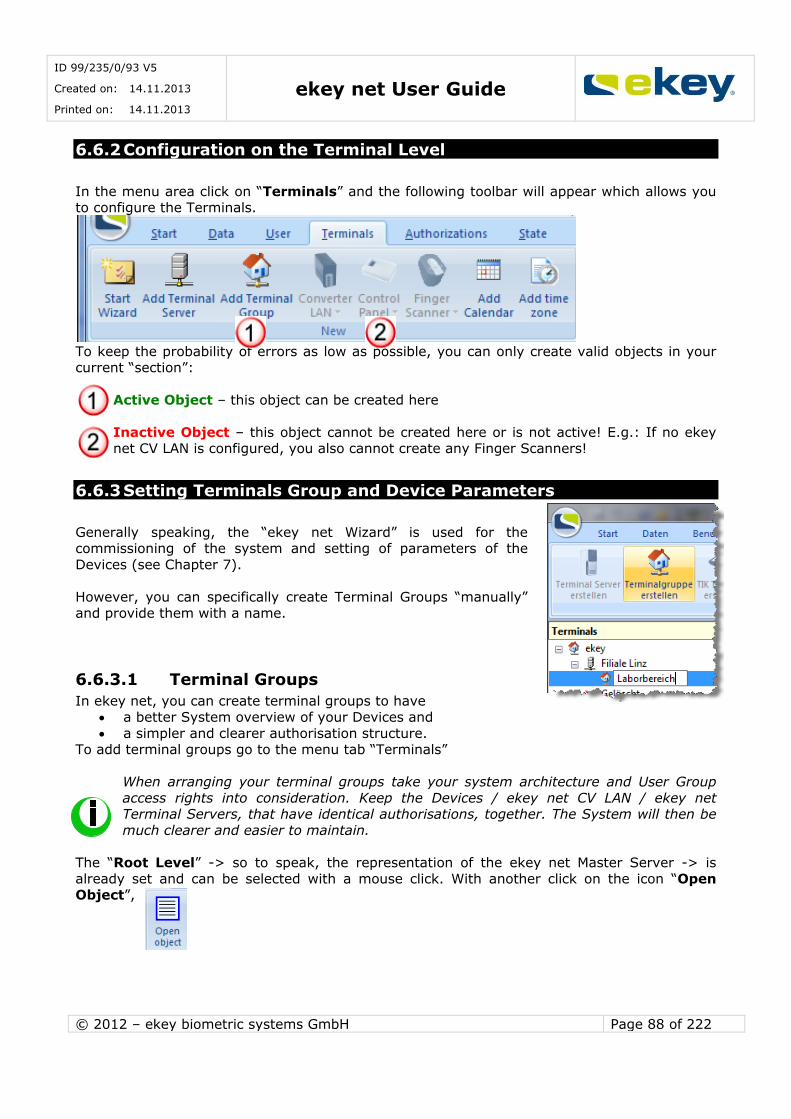
ID 99/235/0/93 V5
Created on: 14.11.2013
Printed on: 14.11.2013 ekey net User Guide
© 2012 – ekey biometric systems GmbH Page 88 of 222
6.6.2 Configuration on the Terminal Level
In the menu area click on “Terminals” and the following toolbar will appear which allows you to configure the Terminals.
To keep the probability of errors as low as possible, you can only create valid objects in your current “section”:
Active Object – this object can be created here
Inactive Object – this object cannot be created here or is not active! E.g.: If no ekey net CV LAN is configured, you also cannot create any Finger Scanners!
6.6.3 Setting Terminals Group and Device Parameters
Generally speaking, the “ekey net Wizard” is used for the commissioning of the system and setting of parameters of the
Devices (see Chapter 7).
However, you can specifically create Terminal Groups “manually”
and provide them with a name.
6.6.3.1 Terminal Groups
In ekey net, you can create terminal groups to have
a better System overview of your Devices and
a simpler and clearer authorisation structure. To add terminal groups go to the menu tab “Terminals”
When arranging your terminal groups take your system architecture and User Group
access rights into consideration. Keep the Devices / ekey net CV LAN / ekey net Terminal Servers, that have identical authorisations, together. The System will then be
much clearer and easier to maintain.
The “Root Level” -> so to speak, the representation of the ekey net Master Server -> is
already set and can be selected with a mouse click. With another click on the icon “Open Object”,
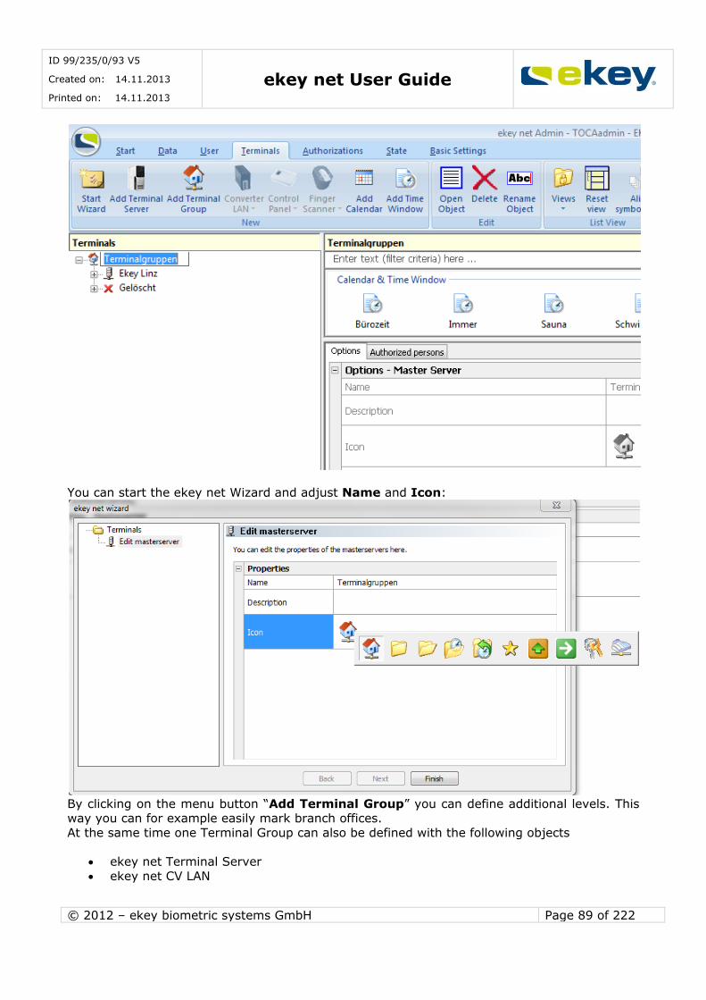
ID 99/235/0/93 V5
Created on: 14.11.2013
Printed on: 14.11.2013 ekey net User Guide
© 2012 – ekey biometric systems GmbH Page 89 of 222
You can start the ekey net Wizard and adjust Name and Icon:
By clicking on the menu button “Add Terminal Group” you can define additional levels. This way you can for example easily mark branch offices.
At the same time one Terminal Group can also be defined with the following objects
ekey net Terminal Server
ekey net CV LAN
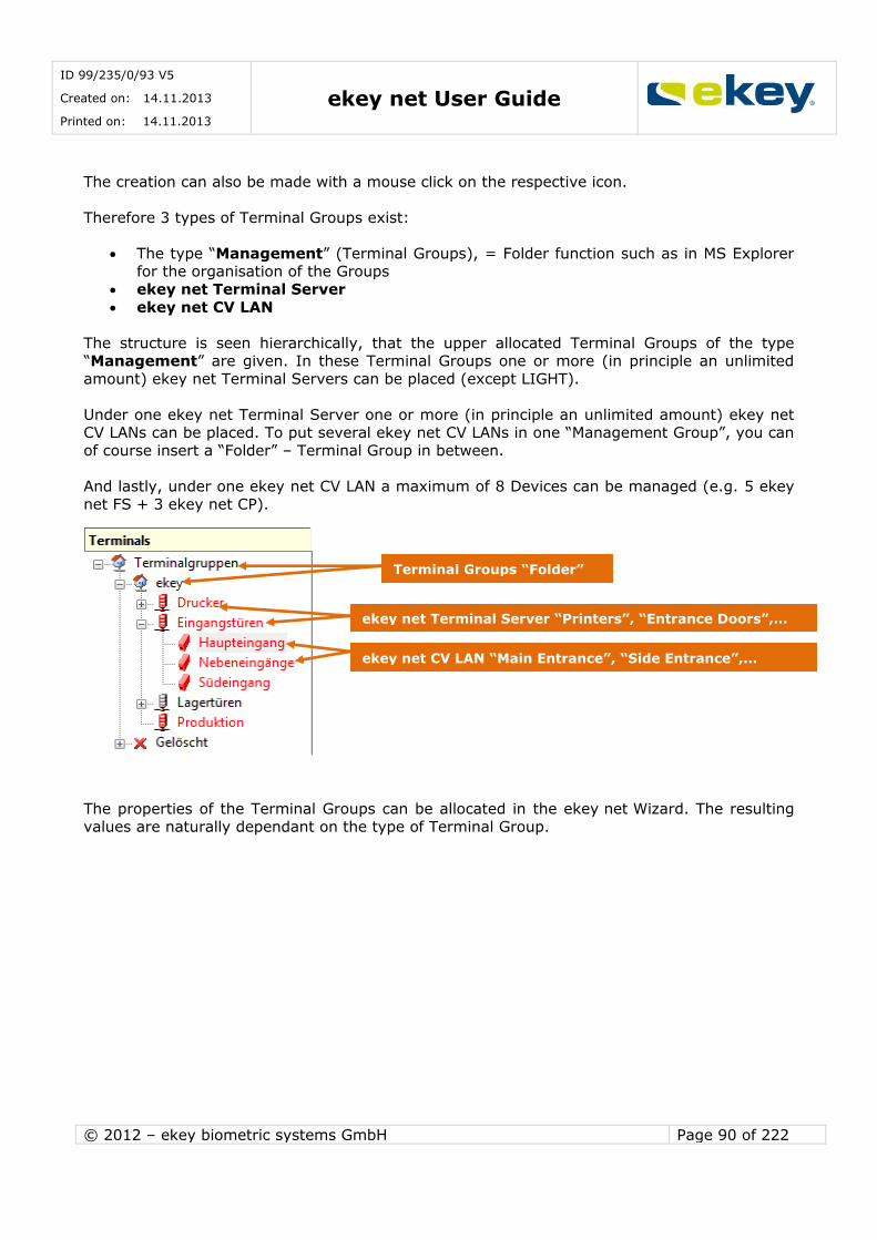
ID 99/235/0/93 V5
Created on: 14.11.2013
Printed on: 14.11.2013 ekey net User Guide
© 2012 – ekey biometric systems GmbH Page 90 of 222
The creation can also be made with a mouse click on the respective icon.
Therefore 3 types of Terminal Groups exist:
The type “Management” (Terminal Groups), = Folder function such as in MS Explorer for the organisation of the Groups
ekey net Terminal Server
ekey net CV LAN
The structure is seen hierarchically, that the upper allocated Terminal Groups of the type “Management” are given. In these Terminal Groups one or more (in principle an unlimited
amount) ekey net Terminal Servers can be placed (except LIGHT).
Under one ekey net Terminal Server one or more (in principle an unlimited amount) ekey net CV LANs can be placed. To put several ekey net CV LANs in one “Management Group”, you can
of course insert a “Folder” – Terminal Group in between.
And lastly, under one ekey net CV LAN a maximum of 8 Devices can be managed (e.g. 5 ekey
net FS + 3 ekey net CP).
The properties of the Terminal Groups can be allocated in the ekey net Wizard. The resulting
values are naturally dependant on the type of Terminal Group.
Terminal Groups “Folder”
ekey net Terminal Server “Printers”, “Entrance Doors”,…
ekey net CV LAN “Main Entrance”, “Side Entrance”,…
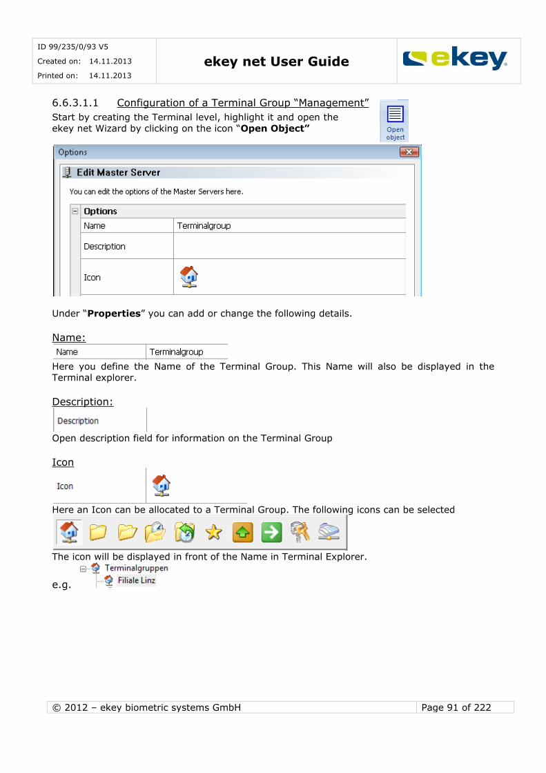
ID 99/235/0/93 V5
Created on: 14.11.2013
Printed on: 14.11.2013 ekey net User Guide
© 2012 – ekey biometric systems GmbH Page 91 of 222
6.6.3.1.1 Configuration of a Terminal Group “Management”
Start by creating the Terminal level, highlight it and open the
ekey net Wizard by clicking on the icon “Open Object”
Under “Properties” you can add or change the following details.
Name:
Here you define the Name of the Terminal Group. This Name will also be displayed in the Terminal explorer.
Description:
Open description field for information on the Terminal Group
Icon
Here an Icon can be allocated to a Terminal Group. The following icons can be selected
The icon will be displayed in front of the Name in Terminal Explorer.
e.g.

ID 99/235/0/93 V5
Created on: 14.11.2013
Printed on: 14.11.2013 ekey net User Guide
© 2012 – ekey biometric systems GmbH Page 92 of 222
Area Limit Actions:
Activate Terminal Groups as area limits. Further details on area limits can be found in Chapter
16.
6.6.3.1.2 Configuration of the Terminal Group “ekey net Terminal Server”
Select the desired ekey net Terminal Server for configuration.
The appropriate configurations are made under Properties.
The ekey net Terminal Server offers a range of additional functions, which go beyond mere
access. Two special options to be called are Notification and Logging.
The following parameters can be set at the ekey net Terminal Server:
Name:
Name of the ekey net Terminal Servers. This also appears in the Terminal Explorer.
Description:
Open description field for information about the Terminal Group
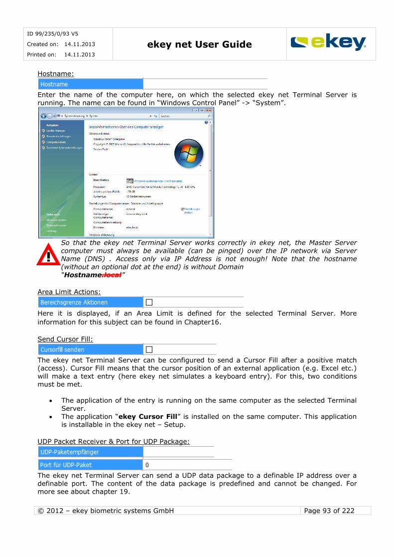
ID 99/235/0/93 V5
Created on: 14.11.2013
Printed on: 14.11.2013 ekey net User Guide
© 2012 – ekey biometric systems GmbH Page 93 of 222
Hostname:
Enter the name of the computer here, on which the selected ekey net Terminal Server is running. The name can be found in “Windows Control Panel” -> “System”.
So that the ekey net Terminal Server works correctly in ekey net, the Master Server
computer must always be available (can be pinged) over the IP network via Server Name (DNS) . Access only via IP Address is not enough! Note that the hostname
(without an optional dot at the end) is without Domain
“Hostname.local”
Area Limit Actions:
Here it is displayed, if an Area Limit is defined for the selected Terminal Server. More
information for this subject can be found in Chapter16. Send Cursor Fill:
The ekey net Terminal Server can be configured to send a Cursor Fill after a positive match (access). Cursor Fill means that the cursor position of an external application (e.g. Excel etc.)
will make a text entry (here ekey net simulates a keyboard entry). For this, two conditions must be met.
The application of the entry is running on the same computer as the selected Terminal
Server.
The application “ekey Cursor Fill” is installed on the same computer. This application is installable in the ekey net – Setup.
UDP Packet Receiver & Port for UDP Package:
The ekey net Terminal Server can send a UDP data package to a definable IP address over a
definable port. The content of the data package is predefined and cannot be changed. For more see about chapter 19.
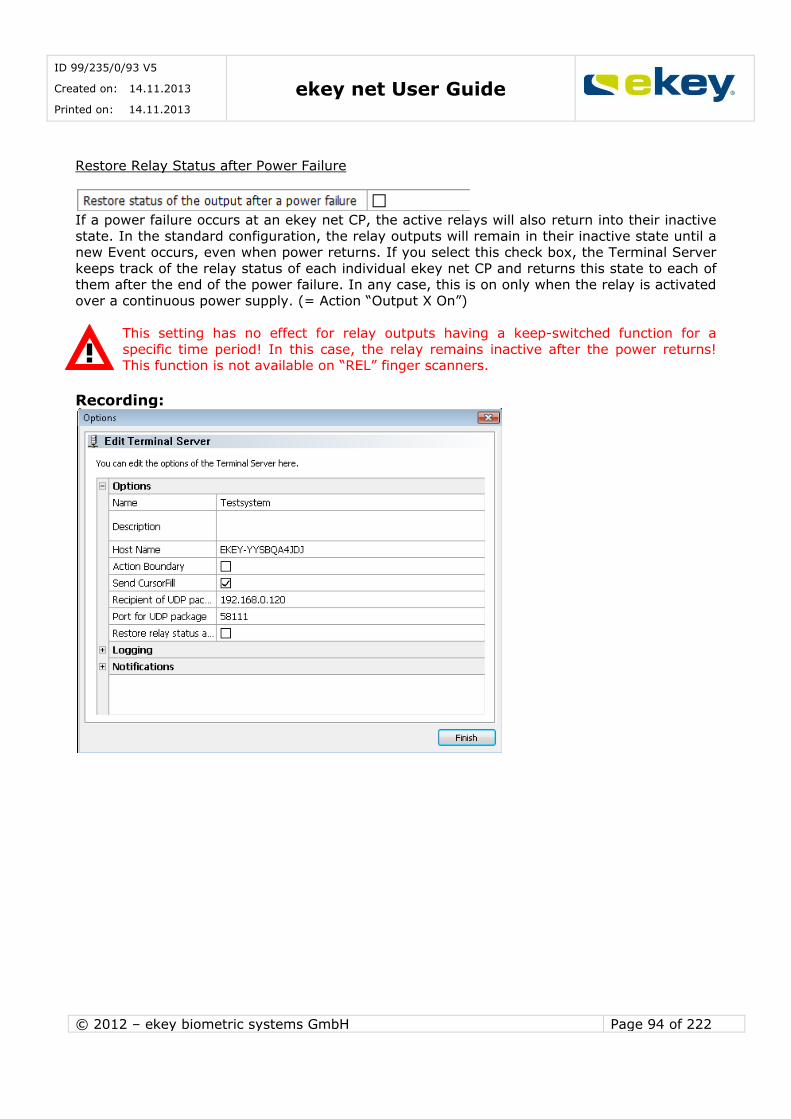
ID 99/235/0/93 V5
Created on: 14.11.2013
Printed on: 14.11.2013 ekey net User Guide
© 2012 – ekey biometric systems GmbH Page 94 of 222
Restore Relay Status after Power Failure
If a power failure occurs at an ekey net CP, the active relays will also return into their inactive
state. In the standard configuration, the relay outputs will remain in their inactive state until a new Event occurs, even when power returns. If you select this check box, the Terminal Server
keeps track of the relay status of each individual ekey net CP and returns this state to each of them after the end of the power failure. In any case, this is on only when the relay is activated
over a continuous power supply. (= Action “Output X On”)
This setting has no effect for relay outputs having a keep-switched function for a
specific time period! In this case, the relay remains inactive after the power returns! This function is not available on “REL” finger scanners.
Recording:
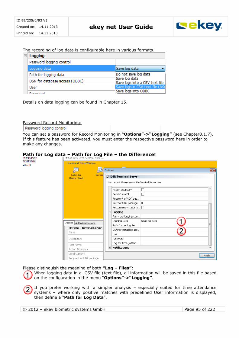
ID 99/235/0/93 V5
Created on: 14.11.2013
Printed on: 14.11.2013 ekey net User Guide
© 2012 – ekey biometric systems GmbH Page 95 of 222
The recording of log data is configurable here in various formats.
Details on data logging can be found in Chapter 15.
Password Record Monitoring:
You can set a password for Record Monitoring in “Options”->“Logging” (see Chapter8.1.7).
If this feature has been activated, you must enter the respective password here in order to make any changes.
Path for Log data – Path for Log File – the Difference!
Please distinguish the meaning of both “Log – Files”:
When logging data in a .CSV file (text file), all information will be saved in this file based on the configuration in the menu “Options”->“Logging”.
If you prefer working with a simpler analysis – especially suited for time attendance
systems – where only positive matches with predefined User information is displayed, then define a “Path for Log Data”.

ID 99/235/0/93 V5
Created on: 14.11.2013
Printed on: 14.11.2013 ekey net User Guide
© 2012 – ekey biometric systems GmbH Page 96 of 222
Finally, you will still have to define all ekey net finger scanners that are meant to log this
data. For this purpose, please activate the respective check box in the Properties of each
Finger Scanner.
Notifications:
It is possible to send the following notifications to defined recipients based on specific system
states or events:
Here are the settings, which were made in the Basic Settings /
Options for the notifications. Select “Default” in order to manage notifications centrally via “Options”. Please refer to Chapter 8.1.1 for further details.
An occurring Event will not result in any notifications to be sent.
For the occured Event an email will be sent to all ekey net
system administrators.
For the occured Event a notification will be sent
only to the ekey net Administrators for this particular terminal group.
To send notifications by e-mail, the settings have to be completed taking your system and server architecture into consideration:
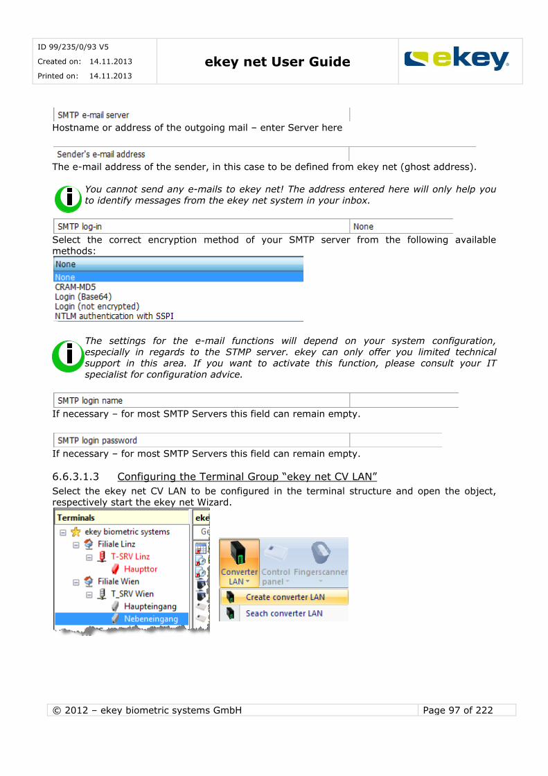
ID 99/235/0/93 V5
Created on: 14.11.2013
Printed on: 14.11.2013 ekey net User Guide
© 2012 – ekey biometric systems GmbH Page 97 of 222
Hostname or address of the outgoing mail – enter Server here
The e-mail address of the sender, in this case to be defined from ekey net (ghost address).
You cannot send any e-mails to ekey net! The address entered here will only help you to identify messages from the ekey net system in your inbox.
Select the correct encryption method of your SMTP server from the following available
methods:
The settings for the e-mail functions will depend on your system configuration,
especially in regards to the STMP server. ekey can only offer you limited technical support in this area. If you want to activate this function, please consult your IT
specialist for configuration advice.
If necessary – for most SMTP Servers this field can remain empty.
If necessary – for most SMTP Servers this field can remain empty.
6.6.3.1.3 Configuring the Terminal Group “ekey net CV LAN”
Select the ekey net CV LAN to be configured in the terminal structure and open the object, respectively start the ekey net Wizard.
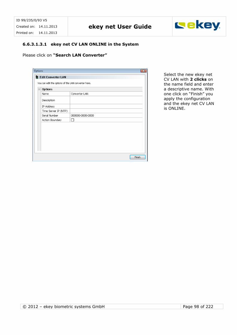
ID 99/235/0/93 V5
Created on: 14.11.2013
Printed on: 14.11.2013 ekey net User Guide
© 2012 – ekey biometric systems GmbH Page 98 of 222
6.6.3.1.3.1 ekey net CV LAN ONLINE in the System
Please click on “Search LAN Converter”
Select the new ekey net
CV LAN with 2 clicks on
the name field and enter a descriptive name. With
one click on “Finish” you apply the configuration
and the ekey net CV LAN is ONLINE.
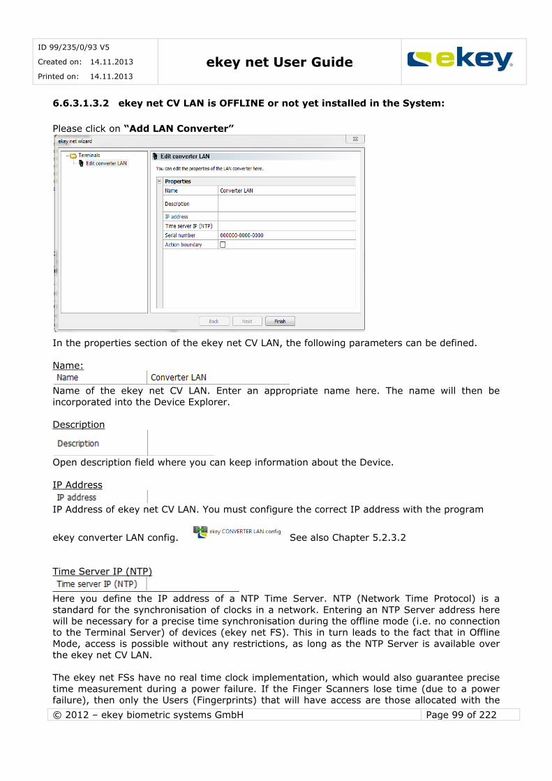
ID 99/235/0/93 V5
Created on: 14.11.2013
Printed on: 14.11.2013 ekey net User Guide
© 2012 – ekey biometric systems GmbH Page 99 of 222
6.6.3.1.3.2 ekey net CV LAN is OFFLINE or not yet installed in the System:
Please click on “Add LAN Converter”
In the properties section of the ekey net CV LAN, the following parameters can be defined.
Name:
Name of the ekey net CV LAN. Enter an appropriate name here. The name will then be
incorporated into the Device Explorer.
Description
Open description field where you can keep information about the Device.
IP Address
IP Address of ekey net CV LAN. You must configure the correct IP address with the program
ekey converter LAN config. See also Chapter 5.2.3.2
Time Server IP (NTP)
Here you define the IP address of a NTP Time Server. NTP (Network Time Protocol) is a
standard for the synchronisation of clocks in a network. Entering an NTP Server address here
will be necessary for a precise time synchronisation during the offline mode (i.e. no connection to the Terminal Server) of devices (ekey net FS). This in turn leads to the fact that in Offline
Mode, access is possible without any restrictions, as long as the NTP Server is available over the ekey net CV LAN.
The ekey net FSs have no real time clock implementation, which would also guarantee precise
time measurement during a power failure. If the Finger Scanners lose time (due to a power failure), then only the Users (Fingerprints) that will have access are those allocated with the
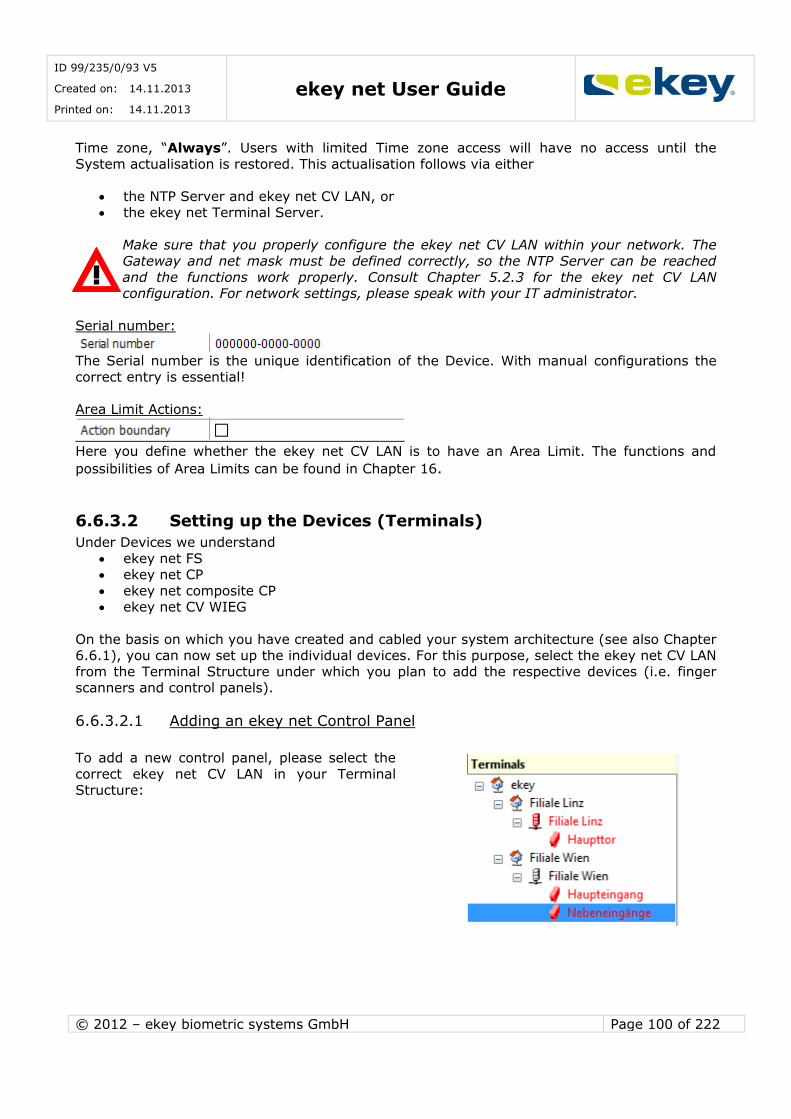
ID 99/235/0/93 V5
Created on: 14.11.2013
Printed on: 14.11.2013 ekey net User Guide
© 2012 – ekey biometric systems GmbH Page 100 of 222
Time zone, “Always”. Users with limited Time zone access will have no access until the
System actualisation is restored. This actualisation follows via either
the NTP Server and ekey net CV LAN, or the ekey net Terminal Server.
Make sure that you properly configure the ekey net CV LAN within your network. The
Gateway and net mask must be defined correctly, so the NTP Server can be reached
and the functions work properly. Consult Chapter 5.2.3 for the ekey net CV LAN configuration. For network settings, please speak with your IT administrator.
Serial number:
The Serial number is the unique identification of the Device. With manual configurations the
correct entry is essential!
Area Limit Actions:
Here you define whether the ekey net CV LAN is to have an Area Limit. The functions and
possibilities of Area Limits can be found in Chapter 16.
6.6.3.2 Setting up the Devices (Terminals)
Under Devices we understand
ekey net FS ekey net CP
ekey net composite CP ekey net CV WIEG
On the basis on which you have created and cabled your system architecture (see also Chapter 6.6.1), you can now set up the individual devices. For this purpose, select the ekey net CV LAN
from the Terminal Structure under which you plan to add the respective devices (i.e. finger scanners and control panels).
6.6.3.2.1 Adding an ekey net Control Panel
To add a new control panel, please select the
correct ekey net CV LAN in your Terminal Structure:
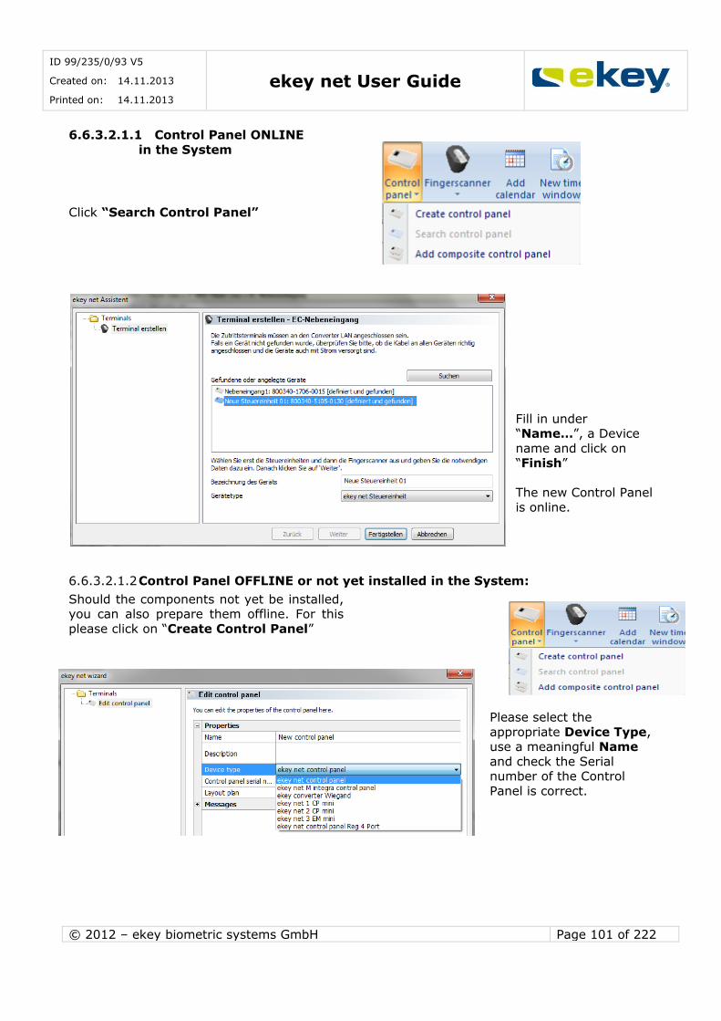
ID 99/235/0/93 V5
Created on: 14.11.2013
Printed on: 14.11.2013 ekey net User Guide
© 2012 – ekey biometric systems GmbH Page 101 of 222
6.6.3.2.1.1 Control Panel ONLINE
in the System
Click “Search Control Panel”
Fill in under “Name…”, a Device
name and click on “Finish”
The new Control Panel
is online.
6.6.3.2.1.2 Control Panel OFFLINE or not yet installed in the System:
Should the components not yet be installed, you can also prepare them offline. For this
please click on “Create Control Panel”
Please select the
appropriate Device Type, use a meaningful Name
and check the Serial number of the Control
Panel is correct.

ID 99/235/0/93 V5
Created on: 14.11.2013
Printed on: 14.11.2013 ekey net User Guide
© 2012 – ekey biometric systems GmbH Page 102 of 222
You find the serial number on the device label. It is a 14 digit number and begins with 8 (e.g.
800340 2209 0001).
The entry of the serial number is absolutely necessary! The devices are identified in the system with the serial number. Enter no serial number, and the devices will not be
known to the system and the function of the device will not be available!
Name:
Enter here a spoken name for the ekey net CP. The name will then be displayed in the terminal
explorer and in device status.
Description:
Empty field for additional information on the ekey net CP
Device Type:
The correct device type should already be selected in the menu. If you see the wrong device instead, you can select the correct one.
(Please double check the entry if the control panel was setup automatically).
In the combo box list, you can see all types of control panels defined in the system along with
client specific generated device types listed (see Chapter 8.1.4.1) Location:
Here you can enter a link to a location (external file). Locations cannot be created from within
ekey net. You can open the link by double clicking. Take note however, of the network
authorisations (the link must be available from the User / computer)
Notifications:
It is possible to send the following notifications to defined recipients based on specific system
states or events:
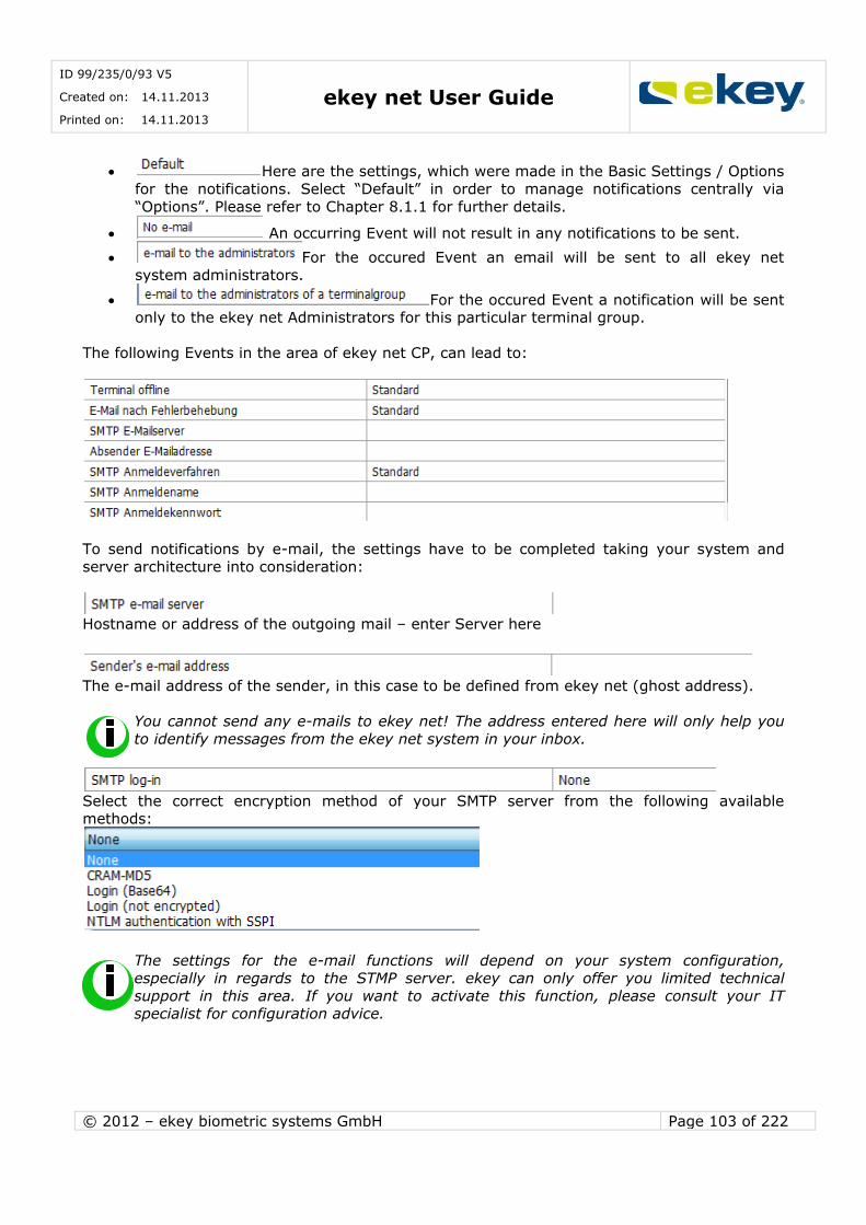
ID 99/235/0/93 V5
Created on: 14.11.2013
Printed on: 14.11.2013 ekey net User Guide
© 2012 – ekey biometric systems GmbH Page 103 of 222
Here are the settings, which were made in the Basic Settings / Options
for the notifications. Select “Default” in order to manage notifications centrally via
“Options”. Please refer to Chapter 8.1.1 for further details.
An occurring Event will not result in any notifications to be sent.
For the occured Event an email will be sent to all ekey net system administrators.
For the occured Event a notification will be sent only to the ekey net Administrators for this particular terminal group.
The following Events in the area of ekey net CP, can lead to:
To send notifications by e-mail, the settings have to be completed taking your system and
server architecture into consideration:
Hostname or address of the outgoing mail – enter Server here
The e-mail address of the sender, in this case to be defined from ekey net (ghost address).
You cannot send any e-mails to ekey net! The address entered here will only help you
to identify messages from the ekey net system in your inbox.
Select the correct encryption method of your SMTP server from the following available methods:
The settings for the e-mail functions will depend on your system configuration,
especially in regards to the STMP server. ekey can only offer you limited technical
support in this area. If you want to activate this function, please consult your IT specialist for configuration advice.
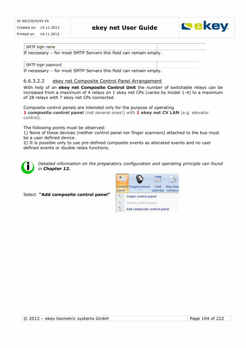
ID 99/235/0/93 V5
Created on: 14.11.2013
Printed on: 14.11.2013 ekey net User Guide
© 2012 – ekey biometric systems GmbH Page 104 of 222
If necessary – for most SMTP Servers this field can remain empty.
If necessary – for most SMTP Servers this field can remain empty.
6.6.3.2.2 ekey net Composite Control Panel Arrangement
With help of an ekey net Composite Control Unit the number of switchable relays can be
increased from a maximum of 4 relays on 1 ekey net CPs (varies by model 1-4) to a maximum of 28 relays with 7 ekey net CPs connected.
Composite control panels are intended only for the purpose of operating
1 composite control panel (not several ones!) with 1 ekey net CV LAN (e.g. elevator control).
The following points must be observed: 1) None of these devices (neither control panel nor finger scanners) attached to the bus must
be a user defined device. 2) It is possible only to use pre-defined composite events as allocated events and no user
defined events or double relais functions.
Detailed information on the preparatory configuration and operating principle can found
in Chapter 12.
Select “Add composite control panel”
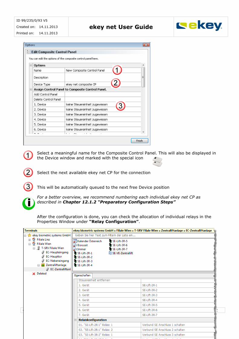
ID 99/235/0/93 V5
Created on: 14.11.2013
Printed on: 14.11.2013 ekey net User Guide
© 2012 – ekey biometric systems GmbH Page 105 of 222
Select a meaningful name for the Composite Control Panel. This will also be displayed in the Device window and marked with the special icon
Select the next available ekey net CP for the connection
This will be automatically queued to the next free Device position
For a better overview, we recommend numbering each individual ekey net CP as described in Chapter 12.1.2 “Preparatory Configuration Steps”
After the configuration is done, you can check the allocation of individual relays in the Properties Window under “Relay Configuration”.
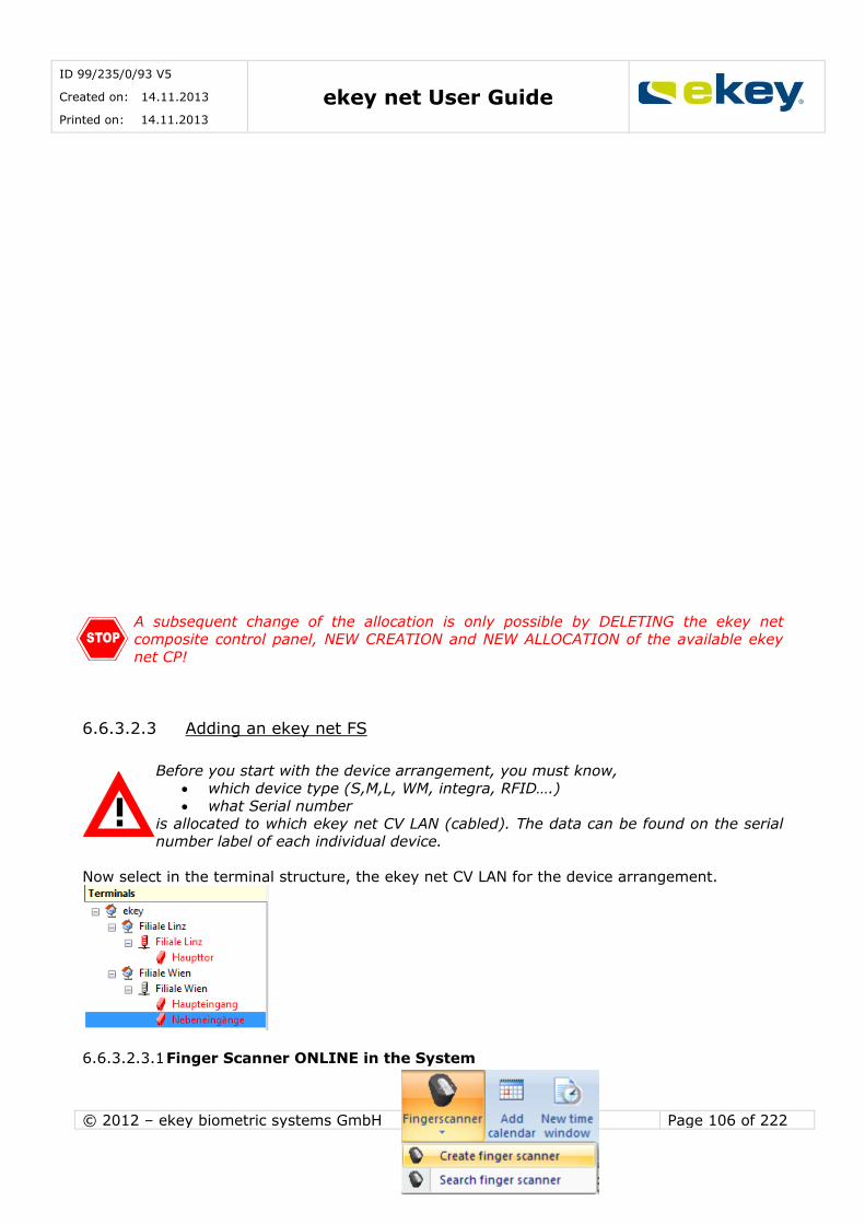
ID 99/235/0/93 V5
Created on: 14.11.2013
Printed on: 14.11.2013 ekey net User Guide
© 2012 – ekey biometric systems GmbH Page 106 of 222
A subsequent change of the allocation is only possible by DELETING the ekey net composite control panel, NEW CREATION and NEW ALLOCATION of the available ekey
net CP!
6.6.3.2.3 Adding an ekey net FS
Before you start with the device arrangement, you must know,
which device type (S,M,L, WM, integra, RFID….) what Serial number
is allocated to which ekey net CV LAN (cabled). The data can be found on the serial number label of each individual device.
Now select in the terminal structure, the ekey net CV LAN for the device arrangement.
6.6.3.2.3.1 Finger Scanner ONLINE in the System
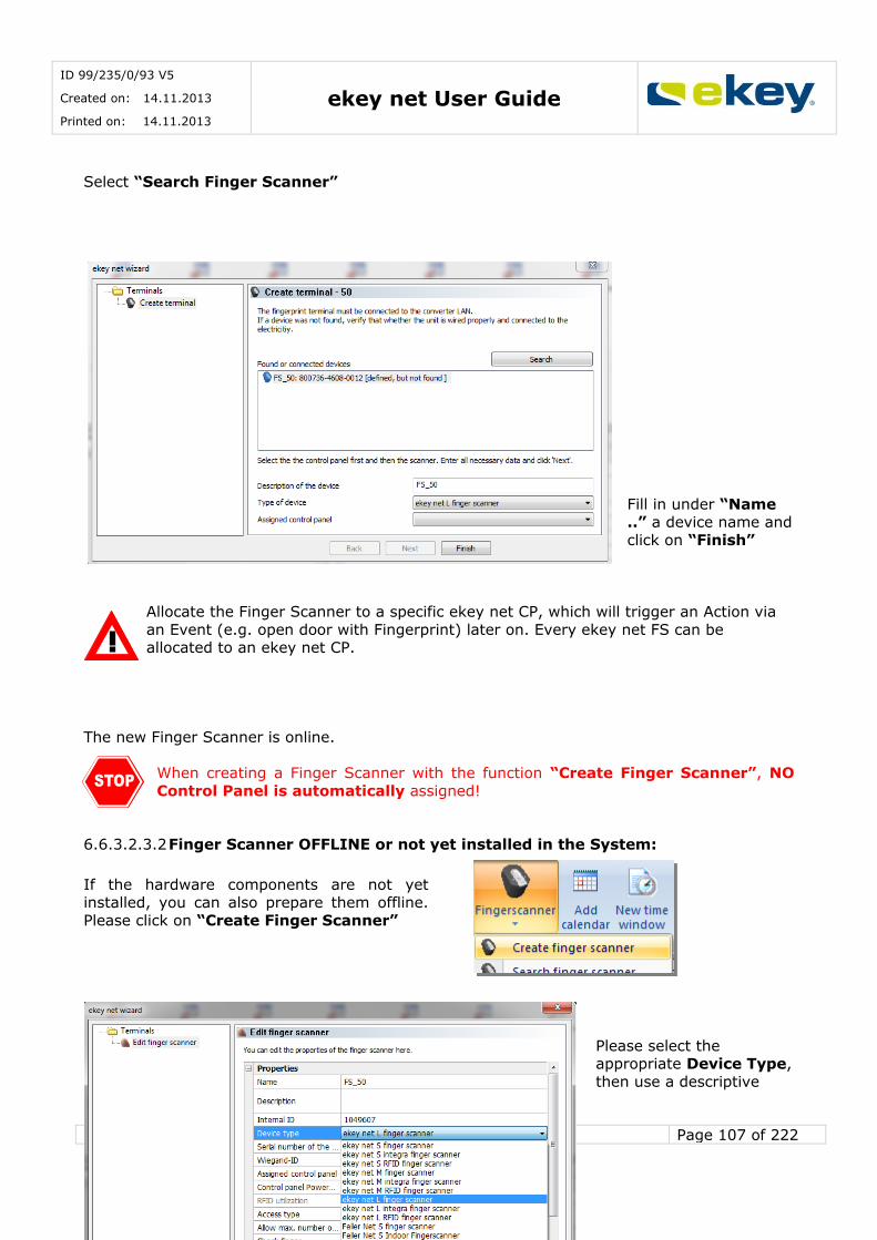
ID 99/235/0/93 V5
Created on: 14.11.2013
Printed on: 14.11.2013 ekey net User Guide
© 2012 – ekey biometric systems GmbH Page 107 of 222
Select “Search Finger Scanner”
Fill in under “Name ..” a device name and
click on “Finish”
Allocate the Finger Scanner to a specific ekey net CP, which will trigger an Action via
an Event (e.g. open door with Fingerprint) later on. Every ekey net FS can be allocated to an ekey net CP.
The new Finger Scanner is online.
When creating a Finger Scanner with the function “Create Finger Scanner”, NO
Control Panel is automatically assigned!
6.6.3.2.3.2 Finger Scanner OFFLINE or not yet installed in the System:
If the hardware components are not yet installed, you can also prepare them offline.
Please click on “Create Finger Scanner”
Please select the appropriate Device Type,
then use a descriptive
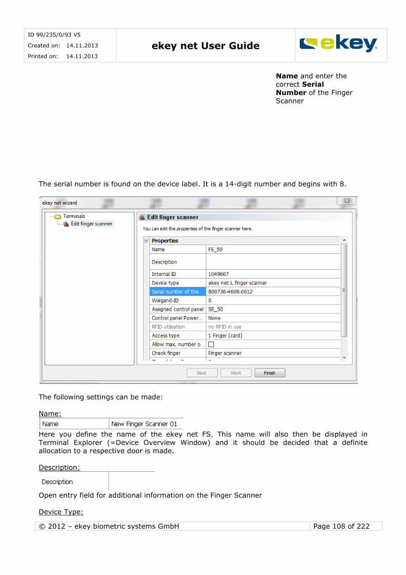
ID 99/235/0/93 V5
Created on: 14.11.2013
Printed on: 14.11.2013 ekey net User Guide
© 2012 – ekey biometric systems GmbH Page 108 of 222
Name and enter the
correct Serial Number of the Finger
Scanner
The serial number is found on the device label. It is a 14-digit number and begins with 8.
The following settings can be made:
Name:
Here you define the name of the ekey net FS. This name will also then be displayed in
Terminal Explorer (=Device Overview Window) and it should be decided that a definite allocation to a respective door is made.
Description:
Open entry field for additional information on the Finger Scanner
Device Type:

ID 99/235/0/93 V5
Created on: 14.11.2013
Printed on: 14.11.2013 ekey net User Guide
© 2012 – ekey biometric systems GmbH Page 109 of 222
The correct device type should already be selected in the menu. If you see the wrong device instead, you can here select the correct one.
In the combo box list, you can see all types of Finger Scanners defined in the system along
with client specific generated device types listed (see Chapter 8.1.4.1).
Finger Scanner Serial Number:
Here is where the serial number of the ekey net FSs is entered. The serial number is found on
the device label. It is a 14 digit number and begins with 8 (e.g. 800321 2209 0003).
The entry of serial number is absolutely necessary! The devices are identified in the
system via this serial number. Enter no serial number, and the devices will not be known to the System and the function of the device will not be available!
Wiegand ID:
The Wiegand ID is given only if you want to send access data over an ekey net Converter Wiegand to a Wiegand System (see Chapter 13).
Assigned Control Panel:
You can allocate a Finger Scanner to a specific ekey net Control Panel, on which an Event (e.g. open door with Fingerprint) will trigger a defined Action later on. Every ekey net FS can be
allocated to a Control Panel.
It is also defined, that with one ekey net FS, a maximum of 4 Actuators (relays) can be switched (Exception Area Switching -> see Chapter 16).
Open the combo box list, so you can see all ekey net CPs listed in your System. The dashed line divides the ekey net CPs which
are in the same Bus segment as the selected Finger Scanner (on the same electrical connection as the ekey net CV LAN) -> above the line
are connected to another Bus segment (to another ekey net CV LAN than the Finger Scanner) ->below the line
In principle, every available Actuator Unit (ekey net CP) can be allocated to an ekey net FS.
However, the Actuator Units which do not belong to the same Bus segment (and
hence are listed under the dashed line) will not support the Offline mode (i.e. ekey net Terminal Server is not active / separated from ekey net CV LAN)!
To secure proper operation when the terminals are offline, please pay attention to
proper wiring and assignment of devices!
Control Panel PowerOn Reset:

ID 99/235/0/93 V5
Created on: 14.11.2013
Printed on: 14.11.2013 ekey net User Guide
© 2012 – ekey biometric systems GmbH Page 110 of 222
The power supply on each finger scanner (PINs 3 and 4) can be managed via the ekey net CP.
This way the power supply for the Finger Scanner can be switched off and the Finger Scanner will be without power.
If the ekey net FS stops responding (monitoring function) for a defined time period of 2 minutes, then the ekey net Terminal Server will interrupt the power supply for the finger
scanner for approximately 3 seconds. You define the ekey net CP that will carry out this reset
here.
You must of course, supply the corresponding finger scanner via the PINs 3 and
4 of the chosen Control Panel. Furthermore you can only define an ekey net CP that belongs to the same Bus
segment as the ekey net FS.
Generally speaking, the ekey net FS complies with the current applicable
electromagnetic standards. However, there might be conditions on site that can lead to a system crash. By activating this function, the system availability can be
improved considerably..
Should an extreme ESD interference occur and cannot be contained (e.g. no
earthing possibilty, long floor covering…), perhaps this shut down cannot be carried out via this ekey net CP. In this unusual case there exists a “special ESD
Configuration” with additional hardware – see Chapter 14
RFID Use:
The ekey net FS RFID can be customised after the basic activation of the RFID functionality in
the Basic Settings – Chapter 8.1.1.2.
The defined RFID function types in the Basic Settings are applicable only with new ekey net FS RFID systems. Individual settings on existing Finger Scanners will not be
updated.
Access type:
The Parameter “Access Type” defines how the ekey net FS decides to trigger an Event (e.g.
open door with Fingerprint). Three possibilities are provided for this.
1 Finger (Card) -> one person must swipe an authorised Fingerprint / Card over the
sensor to trigger the Event (standard application).

ID 99/235/0/93 V5
Created on: 14.11.2013
Printed on: 14.11.2013 ekey net User Guide
© 2012 – ekey biometric systems GmbH Page 111 of 222
2 Different People -> 2 people must swipe their respective Fingerprints over the
sensor to trigger the Event (e.g. for places where 2 people must always be present). The first swiped Fingerprint defines which Event is to be triggered (the first person).
The Fingerprint of the second person serves only as a confirmation. 2 Different Fingerprints -> here 2 different Fingerprints from one person must be
swiped over the Sensor to trigger the Event. The first swiped Fingerprint triggers the Event. The second Fingerprint of the person serves as a confirmation.
Max. Fingers allowed for the L-finger scanner:
The ekey net Finger Scanner type “L” is installed by default settings only with a storage capacity of 200 Fingerprints.
With activation, the maximum storage capacity of the large sized terminal can be
increased to 2.000 finger templates. However, there is a theoretical probability that the occurrence of an individual FAR case will also increase for such an amount of
fingerprint comparisons (matches).
The Fingerprint check will be set to Server matching!
Fingerprint check:
The Fingerprint match (= Template comparison of the swiped Fingerprint with the Fingerprint in the database) will generally be carried out at the Finger Scanner. With an especially large
number of Fingerprints (>200) at the ekey net FS, the checking procedure can take a long time (> 10 seconds up to 50 seconds with 2000 Fingerprints). A possibility of carrying out the
check in an acceptable time is by defining the “Server” Fingerprint check. If more than 200 Fingerprint storage capacity is selected (possible with ekey net FS L), the “Server” will
automatically be set.
Finger Scanner -> Fingerprint check (Matching) will be carried out with ekey net FS (recommended for S and M Types)
Server -> Checking Procedure will be carried out at the ekey net Terminal Server (recommended for L Types)
Fingerprint check “Server” functions only in Online Mode. If the Finger Scanner is
offline (no connection to the ekey net Terminal Server), then the Fingerprint check will be carried out on the Scanner. The access decision may take
considerably longer!
Time-controlled anti-pass back (min)

ID 99/235/0/93 V5
Created on: 14.11.2013
Printed on: 14.11.2013 ekey net User Guide
© 2012 – ekey biometric systems GmbH Page 112 of 222
Users can be blocked for a period of time after access (Anti Pass Back), until they can regain
access (regardless of fingerprint). If a User swipes his Finger across the Sensor within this time (wait time), the User receives a rejection. The wait time is applied always to one User and the
function is valid for all allocated Users in ekey net FS.
The time can be set from 0 … no locking till
60 … 60min
in Minutes.
Web-Logging:
See Web Logging Chapter 15.1.7.
After an update from ekey net 3.x to ekey net 4.x, you must activate Web
Logging for the desired ekey net FS. In earlier versions it was automatically logged.
Web-Log Account:
See Web Log Chapter 15.1.7
Notifications:
It is possible to send the following notifications to defined recipients based on specific system
states or events:
Here are the settings, which were made in the Basic Settings / Options
for the notifications. Select “Default” in order to manage notifications centrally via
“Options”. Please refer to Chapter 8.1.1 for further details.
An occurring Event will not result in any notifications to be sent.
For the occured Event an email will be sent to all ekey net system administrators.
For the occured Event a notification will be sent only to the ekey net Administrators for this particular terminal group.
The following Events in the area of ekey net FS, can lead to:
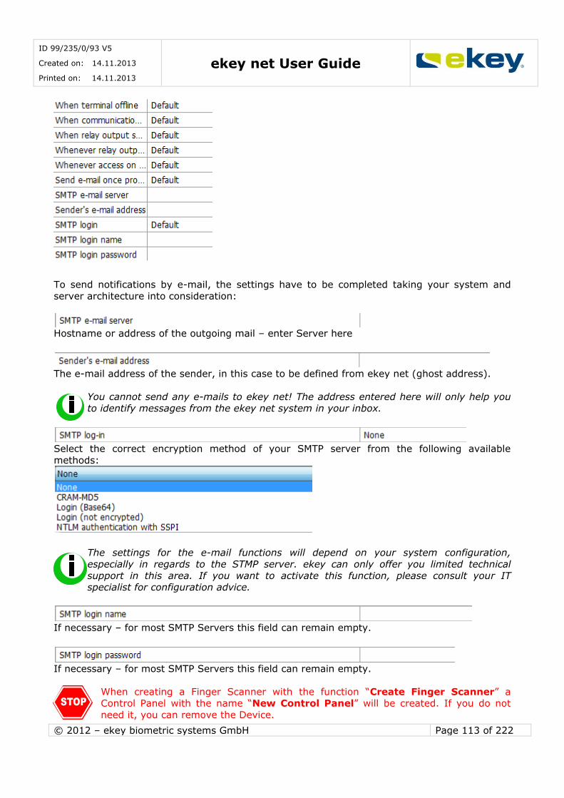
ID 99/235/0/93 V5
Created on: 14.11.2013
Printed on: 14.11.2013 ekey net User Guide
© 2012 – ekey biometric systems GmbH Page 113 of 222
To send notifications by e-mail, the settings have to be completed taking your system and
server architecture into consideration:
Hostname or address of the outgoing mail – enter Server here
The e-mail address of the sender, in this case to be defined from ekey net (ghost address).
You cannot send any e-mails to ekey net! The address entered here will only help you
to identify messages from the ekey net system in your inbox.
Select the correct encryption method of your SMTP server from the following available
methods:
The settings for the e-mail functions will depend on your system configuration,
especially in regards to the STMP server. ekey can only offer you limited technical
support in this area. If you want to activate this function, please consult your IT specialist for configuration advice.
If necessary – for most SMTP Servers this field can remain empty.
If necessary – for most SMTP Servers this field can remain empty.
When creating a Finger Scanner with the function “Create Finger Scanner” a Control Panel with the name “New Control Panel” will be created. If you do not
need it, you can remove the Device.

ID 99/235/0/93 V5
Created on: 14.11.2013
Printed on: 14.11.2013 ekey net User Guide
© 2012 – ekey biometric systems GmbH Page 114 of 222
6.6.3.3 Send Changes to Terminals
After the completion of all settings, click the button
or carry out a “Force Update” according to Chapter 6.5.1.2!
Only now system changes will become effective!!
6.6.4 Editing Terminals and Terminal Groups
6.6.4.1 Changing Parameters
Terminal groups and Terminals can be edited at any time and the appropriate parameters overwritten. Mark the desired object and start the ekey net Wizard.
Modifying object will generally always be done with the Wizard.
Alternatively, use the Open Object button to make the desired
changes.
6.6.4.2 Moving Terminals and Terminal Groups
With drag & drop, you can move Terminals and whole Terminal Groups at any time. However, pay attention to changed access rights!!
6.6.4.3 Force Update
Finally, always carry out a “Force Update” according to Chapter 6.5.1.2. Only now system changes will become effective!!
6.6.5 Deleting Terminals and Terminal Groups
Right click on the Terminal / Terminal Group to be deleted. The context menu appears:
Here select “Delete” or click in the toolbar “Edit” on Delete
By deleting a Terminal Groups all Terminals and Terminal Groups belonging to the selected one are, of course, removed.
Finally, carry out a “Force Update” according to Chapter 6.5.1.2 Only now system changes will become effective!!

ID 99/235/0/93 V5
Created on: 14.11.2013
Printed on: 14.11.2013 ekey net User Guide
© 2012 – ekey biometric systems GmbH Page 115 of 222
Please note that the Terminals will not be immediately irretrievably deleted from the System,
but are moved to the area “X Deleted” in the Terminal Explorer. This allows you to undo accidental changes by using drag & drop and moving the Terminal(Group) back to the “active”
Terminal Group. Only when the contents of “X Deleted” are empty, the data is irretrievably gone.
6.6.6 Time zone
In the Time zone you can define time restrictions for access of Personnel and Personnel Groups
on a daily basis over 7 days of the week. You can define access time to the minute.
In principle, you can define any Time zone in each Terminal Group and also at each
Terminal Level. It is recommended however, to use the smallest valid Time zones as possible to maintain better clarity of the System.
Click in the Terminal Window and select the desired Terminal Group / Terminal.
You now see the Calendar and Time zone in the right window that you can work on in this group. For example:
Here you have the Time zone in the Terminal Group Area “Vienna”
Office time Always
available.
6.6.6.1 Creating a New Time zone
You can now create a new Time zone either
with a right mouse click in the Terminal Group Area, and selecting in the context menu
“New Time zone”
or by clicking in the menu “Add Time zone” on the button

ID 99/235/0/93 V5
Created on: 14.11.2013
Printed on: 14.11.2013 ekey net User Guide
© 2012 – ekey biometric systems GmbH Page 116 of 222
A new Time zone will always be created in the selected Terminal Group. It is set
according to the definitions in Options (Chapter 8.1.1) and inherited to the underlying Groups and Devices.
Now define in the properties window:
Name:
Name of the window. Give a meaningful name for the Time zone (e.g. maintenance, etc.).
Description:
Here you can give an open description that provides further information on the Time zone.
Link Colour:
Here you define the colour displayed of the linking lines of the authorisations (see also Chapter
Fehler! Verweisquelle konnte nicht gefunden werden.). Allocating colour to the line
elps to clarify complex systems.
In the tab “Times”, you can define the actual time effectiveness of this window. Here you define individual time periods over the weekdays, when access can be obtained. You define the
open time periods (keep-switched function) and access rights in special situations (User mode, alarm…)
Time Period Parameters
Day and Special Access Times
Information onTime Periods
Time Periods

ID 99/235/0/93 V5
Created on: 14.11.2013
Printed on: 14.11.2013 ekey net User Guide
© 2012 – ekey biometric systems GmbH Page 117 of 222
To define a time period for access, click in the time bar of the desired day or the special time
(operations holiday, alarm…) and hold down the mouse button. You can now drag a bar to the end of the desired access time.
The colour of the time period bar tells you also which type of time period is available:
… Access
… Access with keep-switched function
… Time period selected for editing
The sum of all time periods defines the functional properties of the Time zone in ekey net!
After completing all entries always click on the button
to confirm the entries. The modified time period data will now be saved. To make them effective in the system, you must then click on
6.6.6.1.1 Time from - until
Define here the time when a User / User Group has access.
The time setting is exact to the minute.
Select, with a right mouse click, the time bar that you want to change. The time bar then appears shaded.
Now you can either enter the time period parameter directly as a value,
or move the bar beginning / end with the mouse (click and hold).
Click in the middle of the bar to move the whole bar.
6.6.6.1.2 Keep-switched function
Please check your locking systems (e.g. door opener, motorised lock, etc.) whether it will support a day/night operating mode (keep-switched function)! Some locks do not
offer this functionality, and a continuous signal (power supply) leads to failure of the locking system!!
The keep-switched function is a special function in ekey net which allows a door to be kept
open continuously (e.g. during shop opening hours).
When the keep-switched function is selected and an authorised Fingerprint is swiped across the Finger Scanner, the corresponding continuous connection is made until
the expiry of the time (UNTIL-time acc. 6.6.6.1.1) the appearance of the Action “Relay Output X Off”.

ID 99/235/0/93 V5
Created on: 14.11.2013
Printed on: 14.11.2013 ekey net User Guide
© 2012 – ekey biometric systems GmbH Page 118 of 222
If a time entry is defined as a keep-switched function, you can see the bar colour and the
information field in the bar, when you move the mouse pointer over the bar.
…Time zone without keep-switched function
…Time zone with keep-switched function
Example John Smith has a right index finger allocated to the “Open Door with Fingerprint”. “Open Door with Fingerprint” leads to the Action “Impulse Switch 1”
Mr. Smith is authorised to the Finger Scanner “FS TOR” in Linz for “Office time” (Bürozeit) access.
“Office time” is defined as follows
From Monday until Friday between 6:00am and 8:00am the door “FS TOR” can be opened by
an impulse to Relay Output 1. According to this Time zone, however, the door cannot be opened continuously. If he swipes his finger after 8 o’clock, the relay keeps switched(switch 1)
until 4:00pm. It stops automatically from 4:00pm until 6:00pm and he can then open the door without activating the keep-switched function.

ID 99/235/0/93 V5
Created on: 14.11.2013
Printed on: 14.11.2013 ekey net User Guide
© 2012 – ekey biometric systems GmbH Page 119 of 222
From 6:00pm until 6:00am, as well as Saturday and Sunday, Mr. Smith will not be granted
access.
The keep-switched function is always activated by presenting an authorized
Finger. A direct time control of the actuators without prior confirmation of an authorised Fingerprint is not possible in ekey net. This way the system secures
that an authorised person is present when the keep-switched function is
activated.
The function is used often for shops, so that clients have unrestricted access throughout the day. Outside of daily opening hours, only authorised users will have access to the premises.
Keep-switched function over midnight:
Generally speaking, the keep-switched function will always have a defined end at which the actuator (Switch) of the allocated Control Panel turns inactive again. If you have, for example,
a time defined from 8:00am until 12:00am, the keep-switched function will be activated on the
Relay Output when swiping a finger after 8:00am, and turn off automatically again at 12:00am.
The same will happen when the Time Period is for instance defined from 1:00pm until
12:00pm. However, there is an exception: If a new Time Period for the relay with the keep-switched
function begins on the next day at 00:00am, the relay output will not be deactivated at midnight but only at the end of the second Time Period! This way, the door remains open over
midnight.
Example:
In this example the keep-switched function would remain effective from Monday 1:00pm until
2:00am the next morning. Saturday, the door will stay locked.
Please note, that a Time-Window could only handle 1 x midnight This is not possible: Start on Monday 12:30 to Wednesday 02:00, the relay would drop off on
Tuesday 24:00.
If you make any changes in the Time zones while working with the keep-switched function (day use), their state will be changed once you “Send
Changes to Terminal”!!! As a result, you will have to reactive the relay with the
keep-switched function by swiping an authorised finger. This will even become effective when making changes in Time zones not using the keep-switched
function. If you do not reactive the correct relay state, the door could remain open when the Time zone was supposed to expire!
6.6.6.1.3 Timed controlled operations

ID 99/235/0/93 V5
Created on: 14.11.2013
Printed on: 14.11.2013 ekey net User Guide
© 2012 – ekey biometric systems GmbH Page 120 of 222
With Version 4.0.6 and above, you can set a self-operating Time-Window, which is working
without any Actions from a finger scanner.
Example: You want that every day from 8:00 to 18:00 a door should stay automatically open.
First you have to create a new Time-Window, see Chapter 6.6.6.1 In the options set it to „ Use Time zone for time controlled operation“
Then you have to select your Control Panel in “Terminals” and under the “Options” check “Time Control” and select here which Relay should work with your new Time-Window.
6.6.6.1.4 Send Changes to Terminals
After completing changes and saving, click on .
Only now system changes will become effective!!
6.6.6.2 Duplicating Time zones
When you already have a Time zone in a similar form to the one you need, you can very simply
duplicate the output Time zone.
Right mouse click on the Time zone and select from the context menu “Duplicate”
6.6.6.3 Editing Time zones (change)
For editing, you must select the desired Time zone with a mouse click.
Change the settings of the desired Time zone analogous to the description in Chapter 6.6.6.1.
Deleting Time Periods To delete a time period, select the bar to be deleted with a right mouse click.
It is then displayed shaded .
Finally, click below right. The selected time period will be deleted.
Filling in All Days
Click on to have all day and special functions set (without the keep-switched function) with a time bar from00:00am – 12:00pm. This way it will correspond to the Time zone
“Always”. You can of course, also adjust it accordingly.
Copying Day Times to other Days
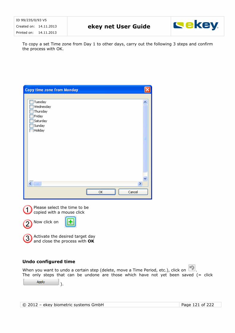
ID 99/235/0/93 V5
Created on: 14.11.2013
Printed on: 14.11.2013 ekey net User Guide
© 2012 – ekey biometric systems GmbH Page 121 of 222
To copy a set Time zone from Day 1 to other days, carry out the following 3 steps and confirm
the process with OK.
Please select the time to be
copied with a mouse click
Now click on
Activate the desired target day and close the process with OK
Undo configured time
When you want to undo a certain step (delete, move a Time Period, etc.), click on . The only steps that can be undone are those which have not yet been saved (= click
).
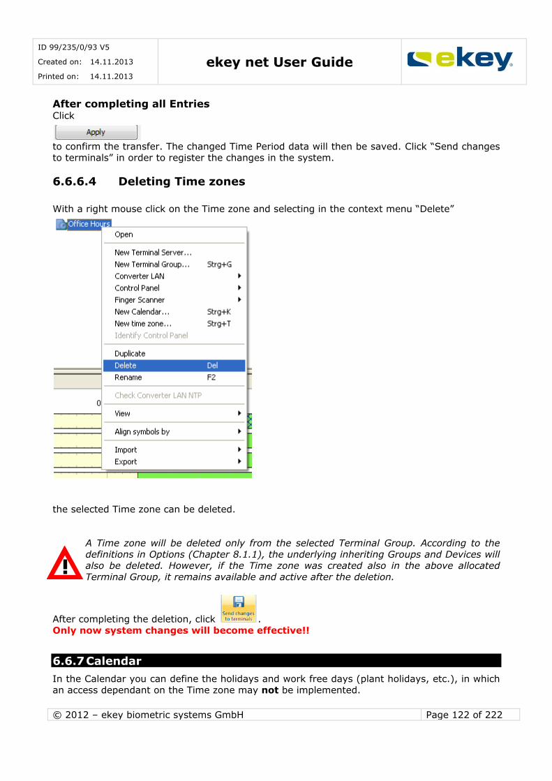
ID 99/235/0/93 V5
Created on: 14.11.2013
Printed on: 14.11.2013 ekey net User Guide
© 2012 – ekey biometric systems GmbH Page 122 of 222
After completing all Entries Click
to confirm the transfer. The changed Time Period data will then be saved. Click “Send changes to terminals” in order to register the changes in the system.
6.6.6.4 Deleting Time zones
With a right mouse click on the Time zone and selecting in the context menu “Delete”
the selected Time zone can be deleted.
A Time zone will be deleted only from the selected Terminal Group. According to the
definitions in Options (Chapter 8.1.1), the underlying inheriting Groups and Devices will also be deleted. However, if the Time zone was created also in the above allocated
Terminal Group, it remains available and active after the deletion.
After completing the deletion, click .
Only now system changes will become effective!!
6.6.7 Calendar
In the Calendar you can define the holidays and work free days (plant holidays, etc.), in which an access dependant on the Time zone may not be implemented.

ID 99/235/0/93 V5
Created on: 14.11.2013
Printed on: 14.11.2013 ekey net User Guide
© 2012 – ekey biometric systems GmbH Page 123 of 222
Excluded from access denial on the Calendar basis, are:
Time zone “Always”
Generally speaking, you can define one or more Calendars to each Terminal Group but also to Terminal levels. It is recommended to use only one Calendar (respectively as few as possible)
within the entire system for easier maintenance. When setting up multiple Calendars, then all of them will be active.
The effective days on which no access is possible, are the sum of all entries in the calendars that are placed in the corresponding Terminal Groups.
6.6.7.1 Creating a New Calendar
You create a new Calendar
With a right mouse click in the Terminal Group Overview and select “New Calendar” in the context menu
or by clicking on the button in the menu “New”.
A New Calendar will be created in the selected Terminal Group, and inherited to
underlying Groups and Devices based on the definitions set in the menu Options (Chapter8.1.1).
Now enter the following data in the properties window of the Calendar.
Name:
Enter a meaningful name for the Calendar here. This is especially useful if you have several Calendars in the System.
Description:
Open description field for further information on the Calendar.
In the Calendar tab, you then see

ID 99/235/0/93 V5
Created on: 14.11.2013
Printed on: 14.11.2013 ekey net User Guide
© 2012 – ekey biometric systems GmbH Page 124 of 222
6.6.7.2 Creating a Calendar
6.6.7.2.1 New Calendar Entry
To make a new calendar entry, click on
“+ Click here for a new entry” To delete a Calendar entry, click on the red cross
“X New Year (Holiday): 31.12.” next to the entry.
Generally, ALL holidays are predefined in the respective calendars. If you only want, for
example, the public holidays, you have to delete all the other ones!
6.6.7.2.2 Parameters
For every Calendar entry you have to define the parameters
Parameters
List of Calendar Entries

ID 99/235/0/93 V5
Created on: 14.11.2013
Printed on: 14.11.2013 ekey net User Guide
© 2012 – ekey biometric systems GmbH Page 125 of 222
Name: Name of the holiday, the free time periods (e.g. New Year, Operations Holiday)
Mode
You can define the properties of the free days / holidays during the year.
Fixed Date: is a day in a defined year – the day does not repeat every year
Fixed Period: is e.g. inventory is always from 27 – 30thof June. Date Every Year: is a fixed date every year, e.g. New Year on 1.1.
Easter Related: The holiday / free day depends on Easter, ekey net calculates Easter until year 2099. Define a holiday that is set every year and doesn’t need a definite date
worked out for every year, e.g. Pentecost.
Advent Related: Analogous to Easter Related Weekday: one day in the month: e.g. every 1st Tuesday in January.
The time entry field changes according to the selected mode.
6.6.7.2.3 Send Changes to Terminals
After completion of setting the parameters, click on .
Only now will the settings be sent to the Terminals and therefore be active!
6.6.7.3 Editing a Calendar
To edit, you must select the desired calendar with a mouse click. Then change the settings analogous as described in Chapter 6.6.7.2.
After completion of the changes click on .
Only now system changes will become effective!!
6.6.7.4 Deleting a Calendar
By right mouse clicking in the Calendar and selecting “Delete” in the context menu
the selected Calendar will be deleted.
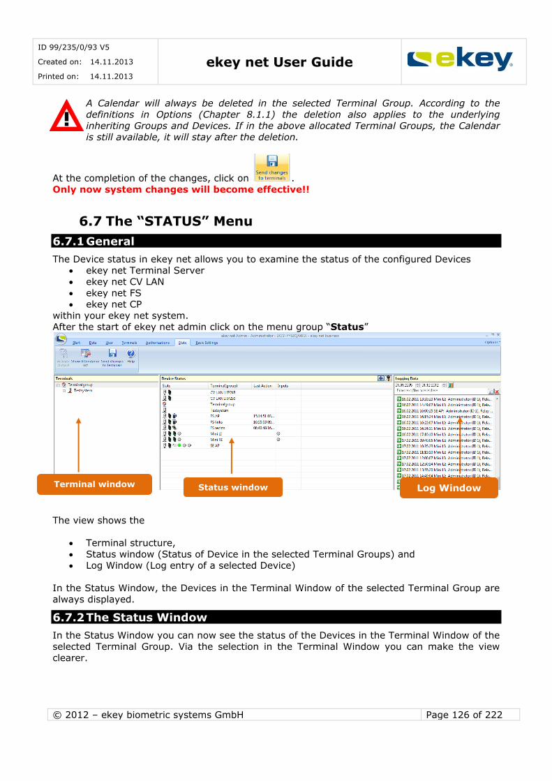
ID 99/235/0/93 V5
Created on: 14.11.2013
Printed on: 14.11.2013 ekey net User Guide
© 2012 – ekey biometric systems GmbH Page 126 of 222
A Calendar will always be deleted in the selected Terminal Group. According to the
definitions in Options (Chapter 8.1.1) the deletion also applies to the underlying inheriting Groups and Devices. If in the above allocated Terminal Groups, the Calendar
is still available, it will stay after the deletion.
At the completion of the changes, click on .
Only now system changes will become effective!!
6.7 The “STATUS” Menu
6.7.1 General
The Device status in ekey net allows you to examine the status of the configured Devices ekey net Terminal Server
ekey net CV LAN
ekey net FS ekey net CP
within your ekey net system. After the start of ekey net admin click on the menu group “Status”
The view shows the
Terminal structure,
Status window (Status of Device in the selected Terminal Groups) and Log Window (Log entry of a selected Device)
In the Status Window, the Devices in the Terminal Window of the selected Terminal Group are
always displayed.
6.7.2 The Status Window
In the Status Window you can now see the status of the Devices in the Terminal Window of the selected Terminal Group. Via the selection in the Terminal Window you can make the view
clearer.
Terminal window Status window Log Window

ID 99/235/0/93 V5
Created on: 14.11.2013
Printed on: 14.11.2013 ekey net User Guide
© 2012 – ekey biometric systems GmbH Page 127 of 222
ekey net CP IN and ekey net CP mini are available for digital input e.g. can be used for door
status monitoring. To see the status of these inputs, the view in the Status Window must be
changed. Please click on the icon in the above right corner of the Status Window.
The view of the Status Window changes as follows:
Devices: the colour shows whether the Device is ONLINE or OFFLINE: Red …. Offlline Grey… Online
Yellow… Action needed on the Device (e.g. pressing a key needed on the Device – “Reset a ekey net CP”)
Switches: (only for ekey net CP and ekey net CPREL): Shows the status of Relay Outputs 1,2 and 3 (from left to right).
Yellow… Status unknown Green… Relay switched Grey… Relay not switched
Firmware Version of the Device: 0.0.0.0 = Version not known
Last Action: Time of the last Action in the Device
Terminal (Groups): Name of the Terminal Groups / Terminals.
Fingers at the last Update: Shows the number of
Fingerprints at Terminal (Finger Scanner). In the display: 0(Maximum Finger
scanner)… the number of Fingerprints is unknown.
e.g. 20 of 2000 means that
20 Fingers of a max of 2000 (L-Finger Scanner) are loaded on the FS.
Users at the last Update: shows the number
of Users that have been loaded on to the Finger Scanner.

ID 99/235/0/93 V5
Created on: 14.11.2013
Printed on: 14.11.2013 ekey net User Guide
© 2012 – ekey biometric systems GmbH Page 128 of 222
The inputs of the ekey net CP mini are mostly used for door status monitoring.
6.7.3 Logging in Device Status
For this, see Chapter 6.3.1.
6.8 The “Basic Settings” Menu
For this, see Chapter 8.
Inputs: Here the status of the inputs is
shown below: Yellow… unknown status
Green… input is closed (short to the input pins)
Grey… input is open .
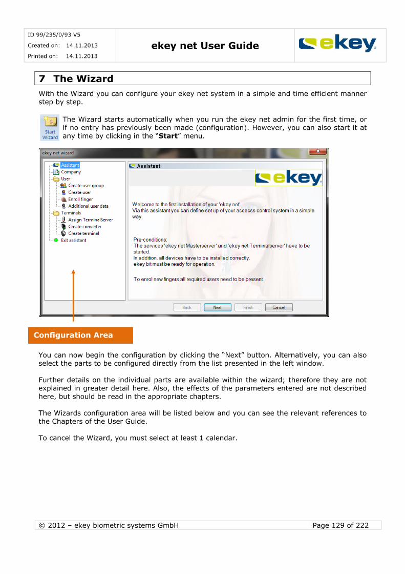
ID 99/235/0/93 V5
Created on: 14.11.2013
Printed on: 14.11.2013 ekey net User Guide
© 2012 – ekey biometric systems GmbH Page 129 of 222
7 The Wizard
With the Wizard you can configure your ekey net system in a simple and time efficient manner step by step.
The Wizard starts automatically when you run the ekey net admin for the first time, or if no entry has previously been made (configuration). However, you can also start it at
any time by clicking in the “Start” menu.
You can now begin the configuration by clicking the “Next” button. Alternatively, you can also select the parts to be configured directly from the list presented in the left window.
Further details on the individual parts are available within the wizard; therefore they are not
explained in greater detail here. Also, the effects of the parameters entered are not described here, but should be read in the appropriate chapters.
The Wizards configuration area will be listed below and you can see the relevant references to
the Chapters of the User Guide.
To cancel the Wizard, you must select at least 1 calendar.
Configuration Area
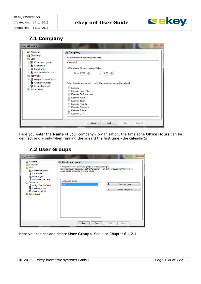
ID 99/235/0/93 V5
Created on: 14.11.2013
Printed on: 14.11.2013 ekey net User Guide
© 2012 – ekey biometric systems GmbH Page 130 of 222
7.1 Company
Here you enter the Name of your company / organisation, the time zone Office Hours can be defined, and – only when running the Wizard the first time –the calendar(s).
7.2 User Groups
Here you can set and delete User Groups. See also Chapter 6.4.2.1

ID 99/235/0/93 V5
Created on: 14.11.2013
Printed on: 14.11.2013 ekey net User Guide
© 2012 – ekey biometric systems GmbH Page 131 of 222
7.3 Create User
Add Users (Chapter 6.4.2.2) and allocate them to User Groups.
7.4 Enrol Finger
Here you can enrol individual Fingerprints for the new User and allocate every finger to an Event (Chapter 6.4.2.2).
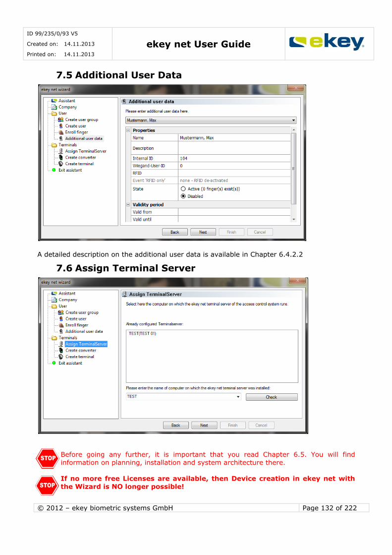
ID 99/235/0/93 V5
Created on: 14.11.2013
Printed on: 14.11.2013 ekey net User Guide
© 2012 – ekey biometric systems GmbH Page 132 of 222
7.5 Additional User Data
A detailed description on the additional user data is available in Chapter 6.4.2.2
7.6 Assign Terminal Server
Before going any further, it is important that you read Chapter 6.5. You will find
information on planning, installation and system architecture there.
If no more free Licenses are available, then Device creation in ekey net with
the Wizard is NO longer possible!
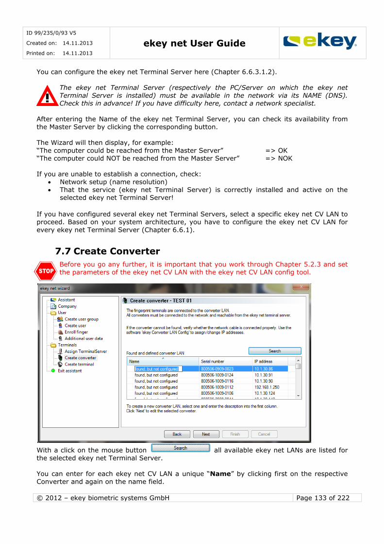
ID 99/235/0/93 V5
Created on: 14.11.2013
Printed on: 14.11.2013 ekey net User Guide
© 2012 – ekey biometric systems GmbH Page 133 of 222
You can configure the ekey net Terminal Server here (Chapter 6.6.3.1.2).
The ekey net Terminal Server (respectively the PC/Server on which the ekey net
Terminal Server is installed) must be available in the network via its NAME (DNS). Check this in advance! If you have difficulty here, contact a network specialist.
After entering the Name of the ekey net Terminal Server, you can check its availability from
the Master Server by clicking the corresponding button.
The Wizard will then display, for example:
“The computer could be reached from the Master Server” => OK “The computer could NOT be reached from the Master Server” => NOK
If you are unable to establish a connection, check:
Network setup (name resolution) That the service (ekey net Terminal Server) is correctly installed and active on the
selected ekey net Terminal Server!
If you have configured several ekey net Terminal Servers, select a specific ekey net CV LAN to
proceed. Based on your system architecture, you have to configure the ekey net CV LAN for
every ekey net Terminal Server (Chapter 6.6.1).
7.7 Create Converter
Before you go any further, it is important that you work through Chapter 5.2.3 and set
the parameters of the ekey net CV LAN with the ekey net CV LAN config tool.
With a click on the mouse button all available ekey net LANs are listed for
the selected ekey net Terminal Server.
You can enter for each ekey net CV LAN a unique “Name” by clicking first on the respective
Converter and again on the name field.
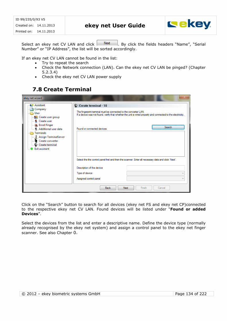
ID 99/235/0/93 V5
Created on: 14.11.2013
Printed on: 14.11.2013 ekey net User Guide
© 2012 – ekey biometric systems GmbH Page 134 of 222
Select an ekey net CV LAN and click . By click the fields headers “Name”, “Serial
Number” or “IP Address”, the list will be sorted accordingly.
If an ekey net CV LAN cannot be found in the list:
Try to repeat the search Check the Network connection (LAN). Can the ekey net CV LAN be pinged? (Chapter
5.2.3.4) Check the ekey net CV LAN power supply
7.8 Create Terminal
Click on the “Search” button to search for all devices (ekey net FS and ekey net CP)connected to the respective ekey net CV LAN. Found devices will be listed under “Found or added
Devices”.
Select the devices from the list and enter a descriptive name. Define the device type (normally
already recognised by the ekey net system) and assign a control panel to the ekey net finger
scanner. See also Chapter 0.
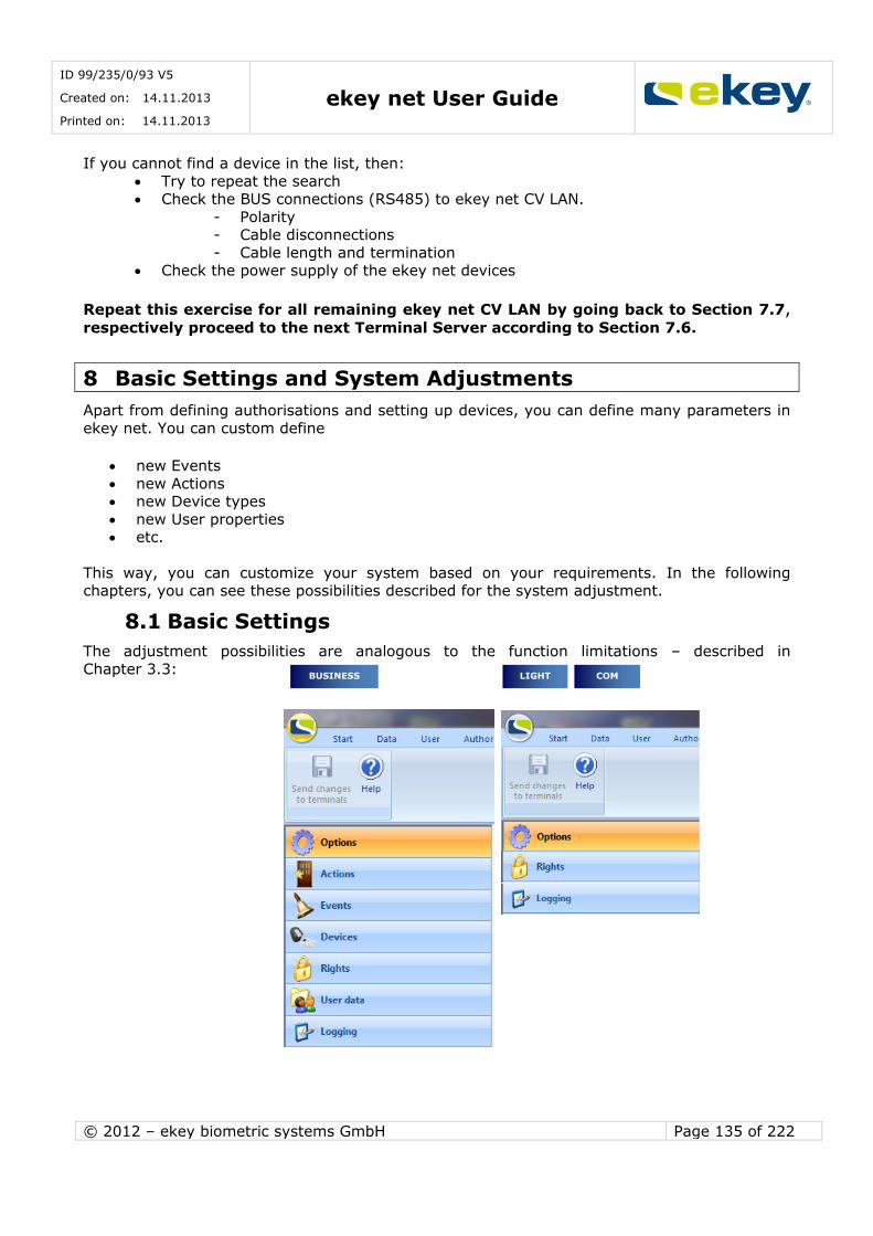
ID 99/235/0/93 V5
Created on: 14.11.2013
Printed on: 14.11.2013 ekey net User Guide
© 2012 – ekey biometric systems GmbH Page 135 of 222
If you cannot find a device in the list, then:
Try to repeat the search Check the BUS connections (RS485) to ekey net CV LAN.
- Polarity - Cable disconnections
- Cable length and termination Check the power supply of the ekey net devices
Repeat this exercise for all remaining ekey net CV LAN by going back to Section 7.7, respectively proceed to the next Terminal Server according to Section 7.6.
8 Basic Settings and System Adjustments
Apart from defining authorisations and setting up devices, you can define many parameters in
ekey net. You can custom define
new Events
new Actions new Device types
new User properties etc.
This way, you can customize your system based on your requirements. In the following chapters, you can see these possibilities described for the system adjustment.
8.1 Basic Settings
The adjustment possibilities are analogous to the function limitations – described in
Chapter 3.3:
LIGHT COM BUSINESS
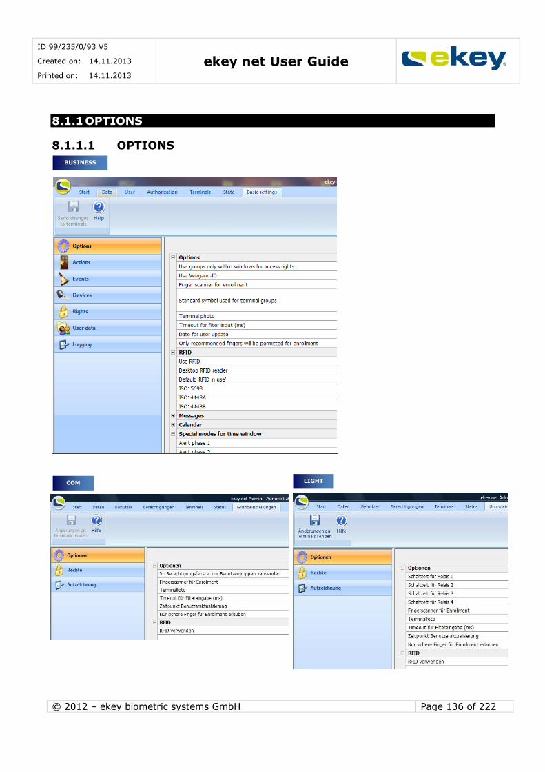
ID 99/235/0/93 V5
Created on: 14.11.2013
Printed on: 14.11.2013 ekey net User Guide
© 2012 – ekey biometric systems GmbH Page 136 of 222
8.1.1 OPTIONS
8.1.1.1 OPTIONS
LIGHT COM
BUSINESS

ID 99/235/0/93 V5
Created on: 14.11.2013
Printed on: 14.11.2013 ekey net User Guide
© 2012 – ekey biometric systems GmbH Page 137 of 222
In the Authorisation Window use only User Groups:
In case you manage a large number of users within the system, the overview in the
Authorisation Window can be improved by activating this function.
Individual Users will no longer be displayed in the User Explorer!
Wiegand ID user:
The field “Wiegand ID” will be displayed in the User and Terminal properties.
Finger Scanner for Enrolment:
To record the Finger Templates either the “USB Device” ekey bit or any ekey net FS can be used.
The final selection of the corresponding ekey net FS can be made
during the actual fingerprint enrolment.
When working in a remote desktop session on the Master Server, the server will in
practise not be physically accessible. Therefore the USB device will be deactivated
automatically, regardless of the settings in “Options”.
Standard Icons for Terminal Groups:
If a new Terminal is created, this icon will be assigned as “Default”. You can change the icon
for each individual Terminal under Properties. The following icons are available:
Timeout for Input Filter
When you write a search term into a filter field (e.g.: User search, Status Display…), after the last key press, the defined value here will be searched in milliseconds, and lastly the search
aborted.
Date for User Update:
BUSINESS
COM LIGHT
BUSINESS
BUSINESS
BUSINESS
COM

ID 99/235/0/93 V5
Created on: 14.11.2013
Printed on: 14.11.2013 ekey net User Guide
© 2012 – ekey biometric systems GmbH Page 138 of 222
The system transfers the learnt finger templates from the function known as “Learning
Finger” at a given point of time to the Finger Scanner (1 x daily). Please choose a point in time when there are little or no users working with the system. During
the data transfer, the fingerprint recognition on the terminal might be slower.
Only recommended fingers will be permitted for enrolment:
To avoid the risk of a falsely recognized fingerprint, which could theoretically occur when
different fingerprint templates are extremely similar, the enrolment of thumbs and little fingers are not permitted by default. Thumbs and little fingers have very few minutiae and comparably
large surface area which cannot be differentiated clearly.
8.1.1.2 RFID
RFID Use:
If you want to activate the RFID functionality for your ekey net finger scanner, this setting has to be set accordingly. Otherwise you cannot use RFID cards for your ekey net terminal.
Attention: You will require a finger scanner equipped with a RFID reader.
Desktop RFID Reader:
You can define the use of a USB RFID reader for reading in the RFID Card ID’s.
Not to Use or Not Available: You can add new RFID cards also directly via the ekey net FS
RFID. TRH-SR-100: USB desktop reader approved and tested by ekey.
Default “RFID Use”
You can define the default settings when creating a new terminal here. Of course, you can also
change the setting on every new terminal on an individual basis. The following default settings are definable:
The RFID Use Types defined in the Basic Settings will only work for new ekey net
FS RFID. Individual settings of existing Finger Scanners will not be updated. Chapter 6.6.3.2.3
BUSINESS
COM LIGHT
BUSINESS
COM LIGHT
BUSINESS
COM LIGHT

ID 99/235/0/93 V5
Created on: 14.11.2013
Printed on: 14.11.2013 ekey net User Guide
© 2012 – ekey biometric systems GmbH Page 139 of 222
The RFID Terminals are supporting ISO15693. The settings made here apply for all RFID
Terminals in the system.
8.1.1.3 NOTIFICATIONS
Below listed Events can be used to send e-mails automatically to a defined recipient:
BUSINESS
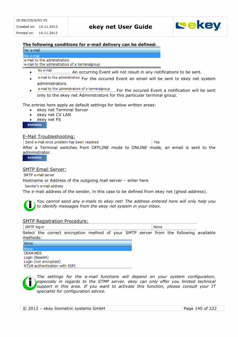
ID 99/235/0/93 V5
Created on: 14.11.2013
Printed on: 14.11.2013 ekey net User Guide
© 2012 – ekey biometric systems GmbH Page 140 of 222
The following conditions for e-mail delivery can be defined:
An occurring Event will not result in any notifications to be sent.
For the occured Event an email will be sent to ekey net system
administrators.
For the occured Event a notification will be sent
only to the ekey net Administrators for this particular terminal group.
The entries here apply as default settings for below written areas: ekey net Terminal Server
ekey net CV LAN ekey net FS
E-Mail Troubleshooting:
After a Terminal switches from OFFLINE mode to ONLINE mode, an email is sent to the
administrator.
SMTP Email Server:
Hostname or Address of the outgoing mail server – enter here
The e-mail address of the sender, in this case to be defined from ekey net (ghost address).
You cannot send any e-mails to ekey net! The address entered here will only help you
to identify messages from the ekey net system in your inbox.
SMTP Registration Procedure:
Select the correct encryption method of your SMTP server from the following available
methods:
The settings for the e-mail functions will depend on your system configuration,
especially in regards to the STMP server. ekey can only offer you limited technical support in this area. If you want to activate this function, please consult your IT
specialist for configuration advice.
BUSINESS
BUSINESS

ID 99/235/0/93 V5
Created on: 14.11.2013
Printed on: 14.11.2013 ekey net User Guide
© 2012 – ekey biometric systems GmbH Page 141 of 222
If necessary – for most SMTP Servers this field can remain empty.
If necessary – for most SMTP Servers this field can remain empty.
8.1.1.4 CALENDAR
Enter additional allocation names here for the Calendar properties (empty = not in use).
Example: Plant holiday, holiday, open door day, staff night…
If you create a new calendar in the “Terminals” area, you can assign the
entries made under allocations there.
BUSINESS
BUSINESS
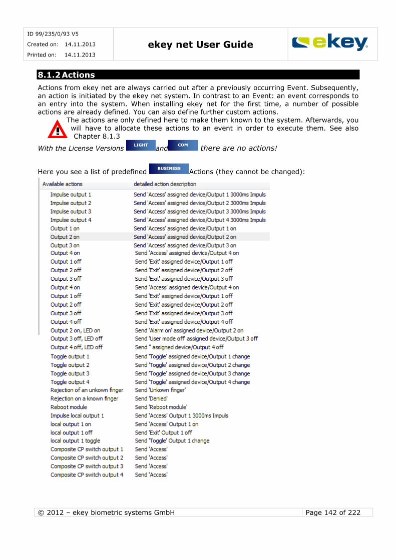
ID 99/235/0/93 V5
Created on: 14.11.2013
Printed on: 14.11.2013 ekey net User Guide
© 2012 – ekey biometric systems GmbH Page 142 of 222
8.1.2 Actions
Actions from ekey net are always carried out after a previously occurring Event. Subsequently,
an action is initiated by the ekey net system. In contrast to an Event: an event corresponds to an entry into the system. When installing ekey net for the first time, a number of possible
actions are already defined. You can also define further custom actions. The actions are only defined here to make them known to the system. Afterwards, you
will have to allocate these actions to an event in order to execute them. See also
Chapter 8.1.3
With the License Versions and there are no actions!
Here you see a list of predefined Actions (they cannot be changed):
BUSINESS
COM LIGHT
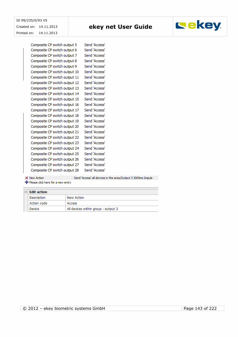
ID 99/235/0/93 V5
Created on: 14.11.2013
Printed on: 14.11.2013 ekey net User Guide
© 2012 – ekey biometric systems GmbH Page 143 of 222
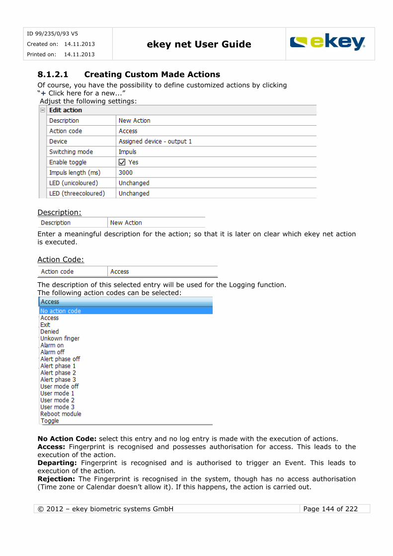
ID 99/235/0/93 V5
Created on: 14.11.2013
Printed on: 14.11.2013 ekey net User Guide
© 2012 – ekey biometric systems GmbH Page 144 of 222
8.1.2.1 Creating Custom Made Actions
Of course, you have the possibility to define customized actions by clicking
“+ Click here for a new...” Adjust the following settings:
Description:
Enter a meaningful description for the action; so that it is later on clear which ekey net action
is executed.
Action Code:
The description of this selected entry will be used for the Logging function. The following action codes can be selected:
No Action Code: select this entry and no log entry is made with the execution of actions. Access: Fingerprint is recognised and possesses authorisation for access. This leads to the
execution of the action. Departing: Fingerprint is recognised and is authorised to trigger an Event. This leads to
execution of the action.
Rejection: The Fingerprint is recognised in the system, though has no access authorisation (Time zone or Calendar doesn’t allow it). If this happens, the action is carried out.

ID 99/235/0/93 V5
Created on: 14.11.2013
Printed on: 14.11.2013 ekey net User Guide
© 2012 – ekey biometric systems GmbH Page 145 of 222
Unrecognised Fingerprint: An unknown Finger is recorded at a Terminal (swiped over
sensor). If this Event occurs, the Action will be carried out. Reboot Module: The Finger Scanner will be restarted
User Modes 1,2 or 3:All devices switch the defined relay outputs within a certain area limit and change the authorisation based on the related Time zone “User Mode 1, 2 or 3”
(predefined). User Mode off: The activated (powered) relay output from the User Mode will be switched
back off (deactivated).
Toggle: The Fingerprint is recognised and is authorised to trigger an Event. This leads to the Action being carried out.
Here, you defined on which device the action is meant to be carried out on. A device is understood in context as an ekey net CP. The name “relay output” points to the corresponding
switching element on the device. For example, the ekey net CPWMis equipped with 3 relay outputs.
The allocation is then: Switch 1 = Relay Output 1
Switch 2 = Relay Output 2 Switch 3 = Relay Output 3
The Following Settings are Available:
Assigned Device: Each ekey net FS is, with integration into the System, in its properties allocated to a Device. Now select “Allocated Device – Switch 1”, and here the defined Action
will be executed on this allocated Device on Relay 1 (or O1). This also applies analogously for:
“Assigned Device – Switch 2” -> Action on Relay Output 2 (or O2) “Assigned Device – Switch 3” -> Action on Relay Output 3 (or O3)
“Assigned Device – Switch 4” -> Action on Relay Output 4 (or O4)
Local Device: With a “Local Device”, the switching element is found directly on the ekey net
FS (e.g. ekey net M FS OM REL). Naturally, no device needs to be allocated to the Terminal properties. Switches 1-4 mean switching elements 1-4. The Action works with one of the
definitions directly on the switch of the Finger Scanner.
The respective terminal used (finger scanner) must of course be equipped with these relay outputs. Please check whether your ekey net finger scanner is equipped with a
relay output / IO port.

ID 99/235/0/93 V5
Created on: 14.11.2013
Printed on: 14.11.2013 ekey net User Guide
© 2012 – ekey biometric systems GmbH Page 146 of 222
All Devices in the Area: Here the actions are executed on all devices (local and also
unallocated) in a defined area. This area limit can be an ekey net CV LAN, a Terminal Server or a Terminal Group (see also Chapter 16 Area Limits).
Switching Mode:
The switching mode defines in which way the switching element (switch 1, 2, 3…) will work on the previously defined device (area, local, allocated).
The following modes can be defined
Impulse: The switching element creates an impulse switch. The relay output is activated
(switches) for a defined time period and then deactivated (switched off) again. The impulse duration is adjustable (see next section).
On: The switching element (relay output) is turned on (= contact NO closes / the exit goes to HIGH) and remains in this state.
Off: The switching element (relay output) is turned off (= contact NO opens / the exit goes
to low) and remains in this state. Toggle: The switching element (relay output) changes its state. If it was Off, it turns On and if
it was On, it turns Off.
Keep-switched function:
The keep-switched function in ekey net is described in another Chapter. The essential
difference to the switching mode ON / IMPULSE (see switching mode), is that the switching is dependent on the Time zone settings. Here you define whether by the execution of an Action,
the keep-switched function for the switching element (switch) is effective or not.
Impulse Duration:
If the switching mode “Impulse” is selected, then you can define the duration of the switching
impulse here when executing an action. The settings here are irrelevant for the switching modes ON, OFF, and TOGGLE.
Range:
100 = 0.1 Seconds 60000 = 60 Seconds
The default value proposed by ekey net is 3000ms (i.e. 3 sec). This way, you are compatible with a majority of door locking systems (motorised locks, etc.)
LED:
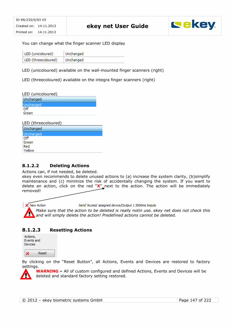
ID 99/235/0/93 V5
Created on: 14.11.2013
Printed on: 14.11.2013 ekey net User Guide
© 2012 – ekey biometric systems GmbH Page 147 of 222
You can change what the finger scanner LED display
LED (unicoloured) available on the wall-mounted finger scanners (right)
LED (threecoloured) available on the integra finger scanners (right)
LED (unicoloured)
LED (threecoloured)
8.1.2.2 Deleting Actions
Actions can, if not needed, be deleted.
ekey even recommends to delete unused actions to (a) increase the system clarity, (b)simplify maintenance and (c) minimize the risk of accidentally changing the system. If you want to
delete an action, click on the red “X” next to the action. The action will be immediately
removed!
Make sure that the action to be deleted is really notin use. ekey net does not check this and will simply delete the action! Predefined actions cannot be deleted.
8.1.2.3 Resetting Actions
By clicking on the “Reset Button”, all Actions, Events and Devices are restored to factory
settings. WARNING – All of custom configured and defined Actions, Events and Devices will be
deleted and standard factory setting restored.
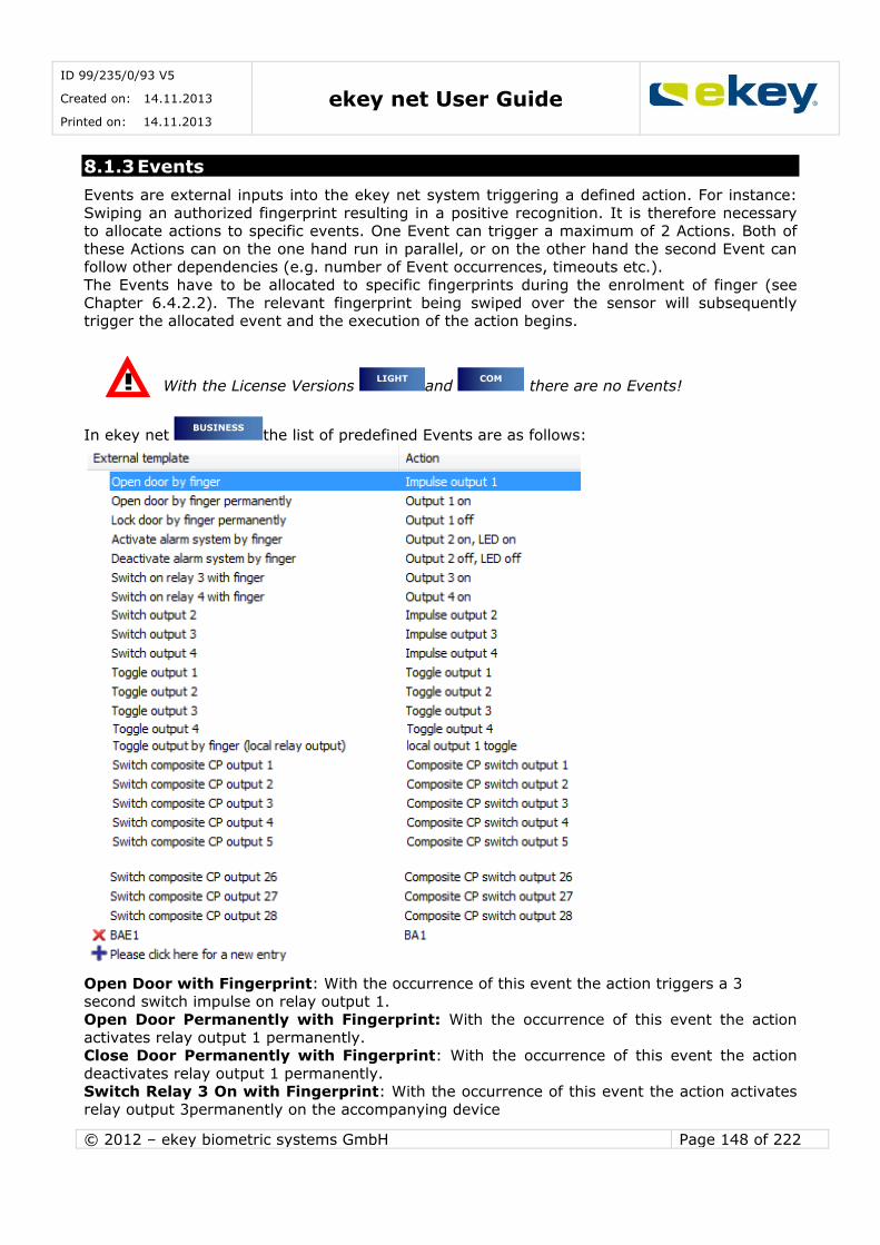
ID 99/235/0/93 V5
Created on: 14.11.2013
Printed on: 14.11.2013 ekey net User Guide
© 2012 – ekey biometric systems GmbH Page 148 of 222
8.1.3 Events
Events are external inputs into the ekey net system triggering a defined action. For instance:
Swiping an authorized fingerprint resulting in a positive recognition. It is therefore necessary to allocate actions to specific events. One Event can trigger a maximum of 2 Actions. Both of
these Actions can on the one hand run in parallel, or on the other hand the second Event can follow other dependencies (e.g. number of Event occurrences, timeouts etc.).
The Events have to be allocated to specific fingerprints during the enrolment of finger (see
Chapter 6.4.2.2). The relevant fingerprint being swiped over the sensor will subsequently trigger the allocated event and the execution of the action begins.
With the License Versions and there are no Events!
In ekey net the list of predefined Events are as follows:
Open Door with Fingerprint: With the occurrence of this event the action triggers a 3 second switch impulse on relay output 1.
Open Door Permanently with Fingerprint: With the occurrence of this event the action
activates relay output 1 permanently. Close Door Permanently with Fingerprint: With the occurrence of this event the action
deactivates relay output 1 permanently. Switch Relay 3 On with Fingerprint: With the occurrence of this event the action activates
relay output 3permanently on the accompanying device
BUSINESS
COM LIGHT

ID 99/235/0/93 V5
Created on: 14.11.2013
Printed on: 14.11.2013 ekey net User Guide
© 2012 – ekey biometric systems GmbH Page 149 of 222
Switch Relay 4 On with Fingerprint: With the occurrence of this event the action activates
relay output 4permanently on the accompanying device Switch Output 2With the occurrence of this event the action triggers a 3 second switch
impulse on relay output 2. Switch Output 3: With the occurrence of this event the action triggers a 3 second switch
impulse on relay output 3. Switch Output 4: With the occurrence of this event the action triggers a 3 second switch
impulse on relay output 4.
Toggle Relay Output 1: With the occurrence of this event the action toggles relay output 1 on the accompanying device (i.e. the relay output changes to the other state -> Off goes to
On). Toggle Relay Output 2: With the occurrence of this event the action toggles relay output 2
on the accompanying device (i.e. the relay output changes to the other state -> Off goes to On).
Toggle Relay Output 3: With the occurrence of this event the action toggles relay output 3 on the accompanying device (i.e. the relay output changes to the other state -> Off goes to
On).
Toggle Relay Output 4: With the occurrence of this event the action toggles relay output 4 on the accompanying device (i.e. the relay output changes to the other state -> Off goes to
On). Rejecting an Unrecognised Fingerprint: The finger scanner rejects a fingerprint that was
not recognised successfully. No further action is triggered. Rejecting a Recognised Fingerprint: The finger scanner rejects a fingerprint that was
recognised successfully. No further Action is triggered. Open Door with Fingerprint (local relay output): With the occurrence of this event the
action triggers a 3 second switch impulse directly on the local relay output of the ekey net
finger scanner. Open Door Permanently with Fingerprint (local relay output):With the occurrence of this
event the action activates the local relay output of the finger scanner permanently. Close Door Permanently with Fingerprint (local relay output): With the occurrence of
this event the action deactivates the local relay output of the finger scanner permanently. Toggle Relay Output with Fingerprint (local relay output): With the occurrence of this
event the action toggles the local relay output of the finger scanner (i.e. the relay output changes to the other state -> Off goes to On).
Switch Composite CP Relay Output “X”: With the occurrence of this event the action
triggers a 3 second switching impulse on the assigned composite switch “X”. It is possible from Switch 1 to Switch 28 – see Chapter 6.6.3.2.2
To use this event, the finger scanner must be equipped with a local relay switch.
The events rejecting recognised or unrecognised fingerprints always refer to the data on individual finger scanners. For example, “Reject Unrecognised Finger” means that the
fingerprint is not recorded on that specific finger scanner. However, it may well be that
the fingerprint is recorded in another finger scanner within the same system.
The rejection events in the default configuration lead to no direct switching actions.
However, you can allocate it to other actions (for this, see “User Defined Events” further down in the Chapter). For example, Switch 2 switches and connects to a camera. So
you can for example, take photo evidence of unauthorised use of your system.

ID 99/235/0/93 V5
Created on: 14.11.2013
Printed on: 14.11.2013 ekey net User Guide
© 2012 – ekey biometric systems GmbH Page 150 of 222
8.1.3.1 Creating User Defined Events
You have the possibility of defining customized events by clicking
“+ Click here for a new entry”
Enter the following settings:
Description:
Label the event descriptively, so it is clear which external input in the system will follow.
Action:
Select the respective action to be triggered either from the predefined or customized actions.
Actions can also be openly defined. The selected action be triggered when the allocated event
occurs.
Counter:
One event can also trigger 2 actions. The counter defines the point in time for triggering the “Action by Counter” (=2nd action). The set count value means that the event of the set number
of the count value must occur accordingly so that the “Action by Counter” will be triggered. Setting range: 1… 100
If it is set to 1 or 0 then the “action“ and “Action by Counter” is executed in parallel.
Reset:
Reset refers to the previously mentioned counter. If the “Action by Counter” is executed, then the Counter is automatically set back to 0. Alternatively, the counter can also be reset because
of the following conditions:
If the Counter is reset, no execution is performed by the “Action by Counter” Never: Counter value is reset only at “Counter End”, i.e. when the Event has occurred the
amount of times that was defined in the Counter. Through other Events: with any other defined event on the ekey net FS, the Counter will be
reset. Timeout: the Counter can also be reset after a certain time. The time is defined in the next
entry field “Timeout in Seconds”.
Through other Events or Timeout: The combination of other Events and Timeout is also possible.
To have the action carried out and the counter ended, the event must happen on the
same ekey net FS (Terminal) as the relevant count. The same applies for reset at the
counter end. How often the event is carried out in the whole system (the Event could occur on several Finger Scanners), is irrelevant.
Timeout in Seconds
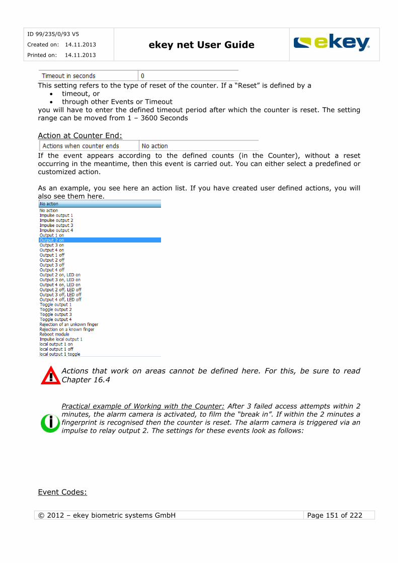
ID 99/235/0/93 V5
Created on: 14.11.2013
Printed on: 14.11.2013 ekey net User Guide
© 2012 – ekey biometric systems GmbH Page 151 of 222
This setting refers to the type of reset of the counter. If a “Reset” is defined by a
timeout, or through other Events or Timeout
you will have to enter the defined timeout period after which the counter is reset. The setting range can be moved from 1 – 3600 Seconds
Action at Counter End:
If the event appears according to the defined counts (in the Counter), without a reset
occurring in the meantime, then this event is carried out. You can either select a predefined or customized action.
As an example, you see here an action list. If you have created user defined actions, you will
also see them here.
Actions that work on areas cannot be defined here. For this, be sure to read Chapter 16.4
Practical example of Working with the Counter: After 3 failed access attempts within 2 minutes, the alarm camera is activated, to film the “break in”. If within the 2 minutes a
fingerprint is recognised then the counter is reset. The alarm camera is triggered via an
impulse to relay output 2. The settings for these events look as follows:
Event Codes:
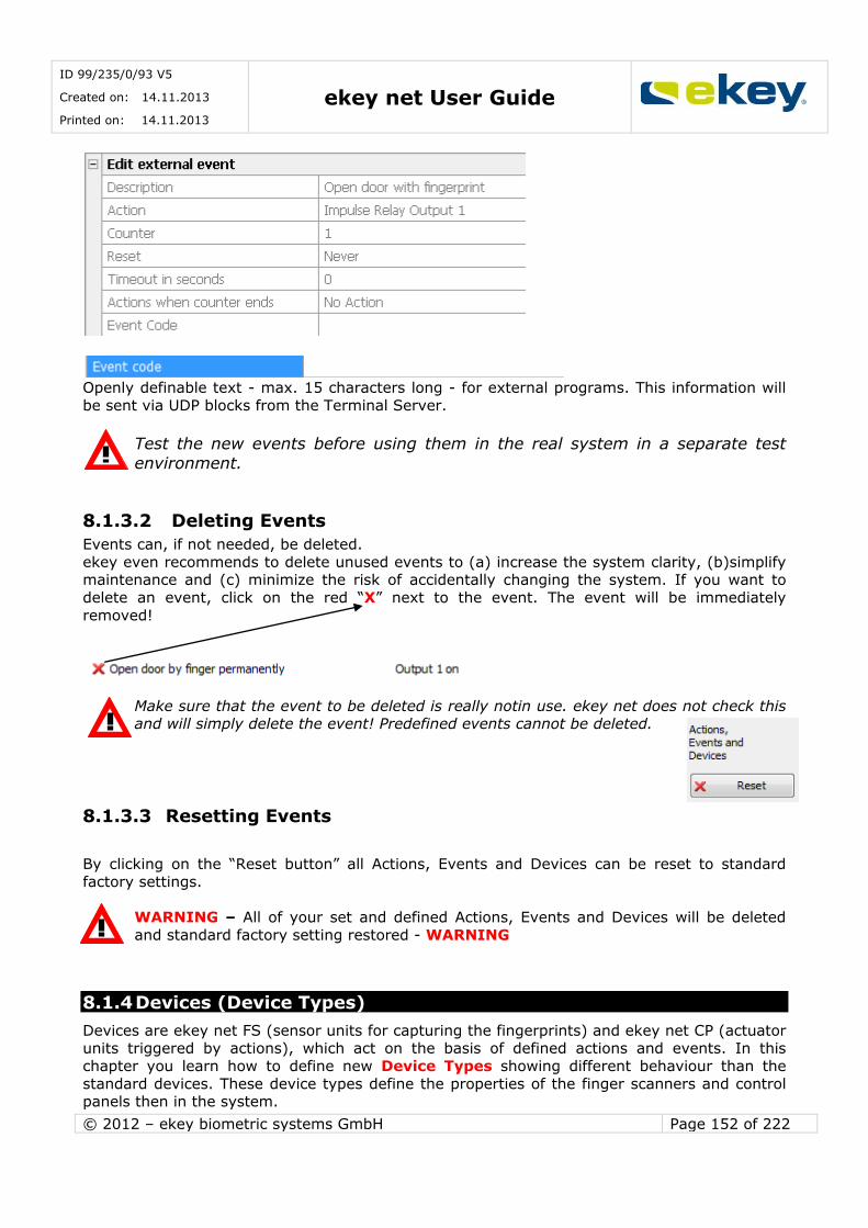
ID 99/235/0/93 V5
Created on: 14.11.2013
Printed on: 14.11.2013 ekey net User Guide
© 2012 – ekey biometric systems GmbH Page 152 of 222
Openly definable text - max. 15 characters long - for external programs. This information will
be sent via UDP blocks from the Terminal Server.
Test the new events before using them in the real system in a separate test
environment.
8.1.3.2 Deleting Events
Events can, if not needed, be deleted.
ekey even recommends to delete unused events to (a) increase the system clarity, (b)simplify maintenance and (c) minimize the risk of accidentally changing the system. If you want to
delete an event, click on the red “X” next to the event. The event will be immediately
removed!
Make sure that the event to be deleted is really notin use. ekey net does not check this and will simply delete the event! Predefined events cannot be deleted.
8.1.3.3 Resetting Events
By clicking on the “Reset button” all Actions, Events and Devices can be reset to standard
factory settings.
WARNING – All of your set and defined Actions, Events and Devices will be deleted
and standard factory setting restored - WARNING
8.1.4 Devices (Device Types)
Devices are ekey net FS (sensor units for capturing the fingerprints) and ekey net CP (actuator units triggered by actions), which act on the basis of defined actions and events. In this
chapter you learn how to define new Device Types showing different behaviour than the
standard devices. These device types define the properties of the finger scanners and control panels then in the system.
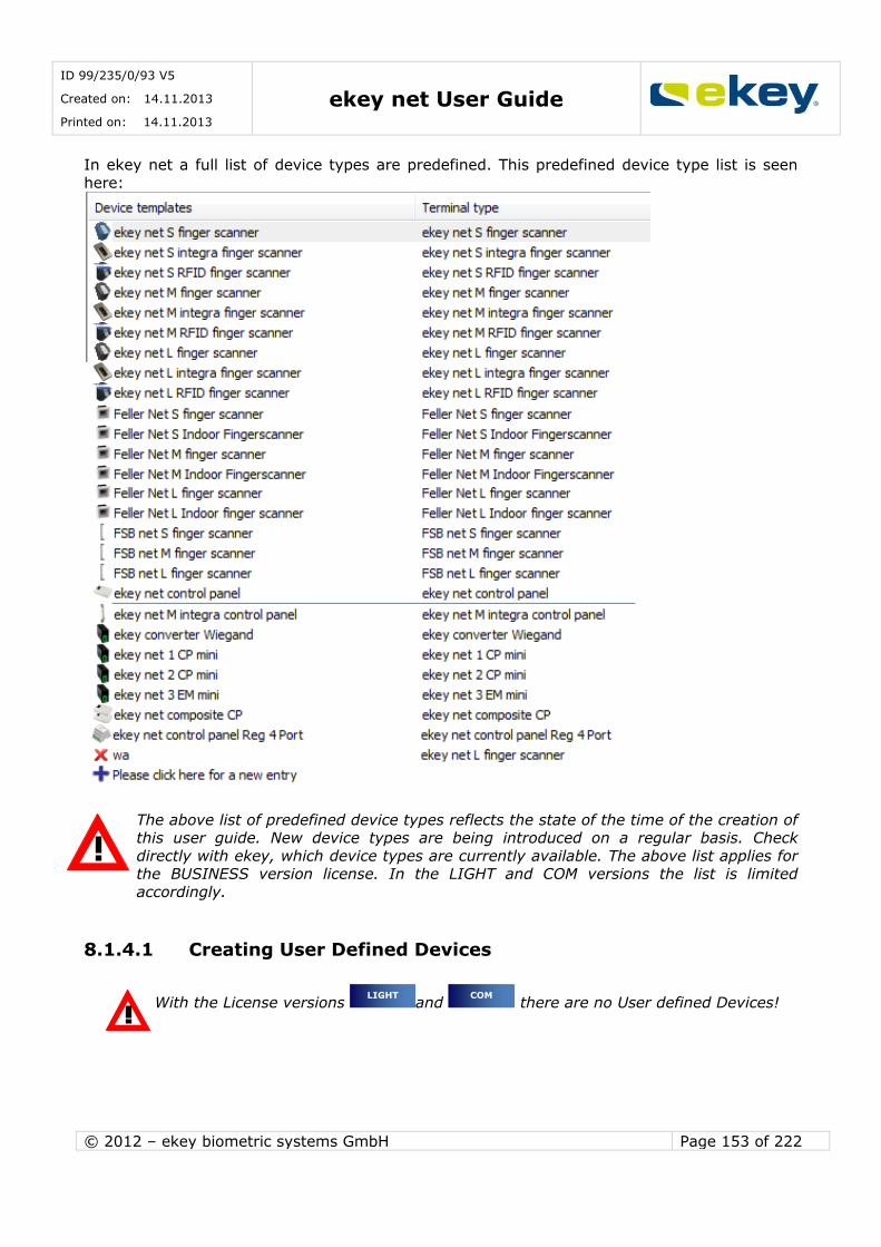
ID 99/235/0/93 V5
Created on: 14.11.2013
Printed on: 14.11.2013 ekey net User Guide
© 2012 – ekey biometric systems GmbH Page 153 of 222
In ekey net a full list of device types are predefined. This predefined device type list is seen
here:
The above list of predefined device types reflects the state of the time of the creation of this user guide. New device types are being introduced on a regular basis. Check
directly with ekey, which device types are currently available. The above list applies for the BUSINESS version license. In the LIGHT and COM versions the list is limited
accordingly.
8.1.4.1 Creating User Defined Devices
With the License versions and there are no User defined Devices!
COM LIGHT
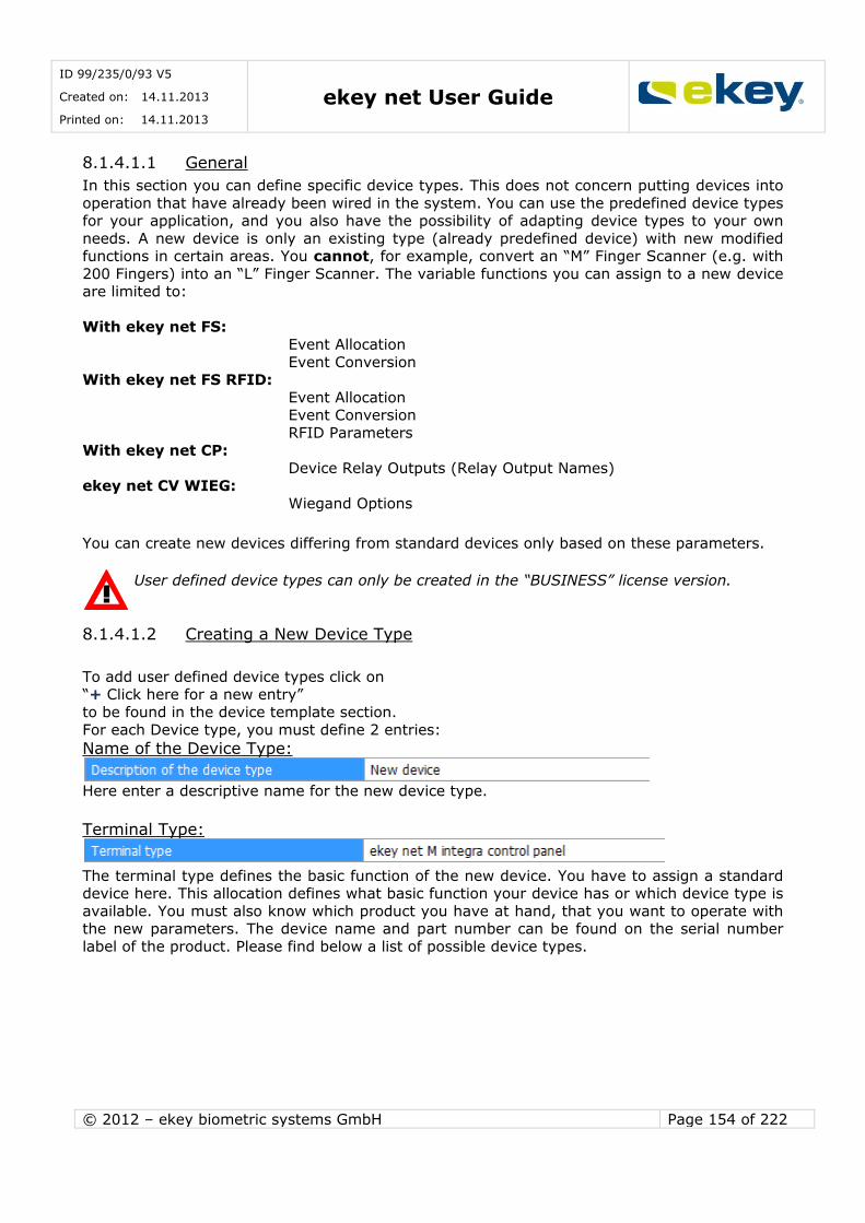
ID 99/235/0/93 V5
Created on: 14.11.2013
Printed on: 14.11.2013 ekey net User Guide
© 2012 – ekey biometric systems GmbH Page 154 of 222
8.1.4.1.1 General
In this section you can define specific device types. This does not concern putting devices into
operation that have already been wired in the system. You can use the predefined device types for your application, and you also have the possibility of adapting device types to your own
needs. A new device is only an existing type (already predefined device) with new modified functions in certain areas. You cannot, for example, convert an “M” Finger Scanner (e.g. with
200 Fingers) into an “L” Finger Scanner. The variable functions you can assign to a new device are limited to:
With ekey net FS:
Event Allocation
Event Conversion With ekey net FS RFID:
Event Allocation Event Conversion
RFID Parameters With ekey net CP:
Device Relay Outputs (Relay Output Names) ekey net CV WIEG:
Wiegand Options
You can create new devices differing from standard devices only based on these parameters.
User defined device types can only be created in the “BUSINESS” license version.
8.1.4.1.2 Creating a New Device Type
To add user defined device types click on “+ Click here for a new entry”
to be found in the device template section.
For each Device type, you must define 2 entries:
Name of the Device Type:
Here enter a descriptive name for the new device type.
Terminal Type:
The terminal type defines the basic function of the new device. You have to assign a standard device here. This allocation defines what basic function your device has or which device type is
available. You must also know which product you have at hand, that you want to operate with the new parameters. The device name and part number can be found on the serial number
label of the product. Please find below a list of possible device types.
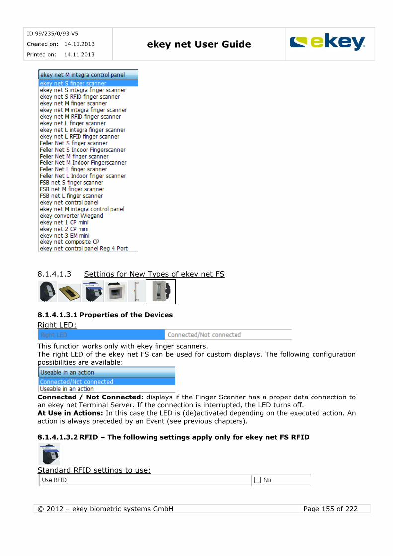
ID 99/235/0/93 V5
Created on: 14.11.2013
Printed on: 14.11.2013 ekey net User Guide
© 2012 – ekey biometric systems GmbH Page 155 of 222
8.1.4.1.3 Settings for New Types of ekey net FS
8.1.4.1.3.1 Properties of the Devices
Right LED:
This function works only with ekey finger scanners.
The right LED of the ekey net FS can be used for custom displays. The following configuration possibilities are available:
Connected / Not Connected: displays if the Finger Scanner has a proper data connection to an ekey net Terminal Server. If the connection is interrupted, the LED turns off.
At Use in Actions: In this case the LED is (de)activated depending on the executed action. An
action is always preceded by an Event (see previous chapters).
8.1.4.1.3.2 RFID – The following settings apply only for ekey net FS RFID
Standard RFID settings to use:

ID 99/235/0/93 V5
Created on: 14.11.2013
Printed on: 14.11.2013 ekey net User Guide
© 2012 – ekey biometric systems GmbH Page 156 of 222
If “Yes” is selected here then the settings in the “Options” tab apply (see Chapter 8.1.1). With
“NO” you can define the configuration different to the default for this finger scanner type. These settings are related to the possible communications protocols (=RFID card) the finger
scanner is able to recognise.
Make your selection here.
Even though you can enter other settings than the default configuration, we
recommend that you stay with the default ones. The System will remain easier to maintain this way.
8.1.4.1.3.3 Event Allocation
Event with Rejection of Unrecognised Fingerprint:
The new predefined finger scanner can trigger an appropriate event with an unrecognised
fingerprint. The corresponding event can be selected here. You can find in this list also the user defined events. When working with factory settings, the following events are selectable:
For standard devices the event “Rejecting Unrecognised Fingerprint” is predefined.
Event with Rejection of Recognised Fingerprint:
If a fingerprint is swiped over the sensor in ekey net and subsequently recognised successfully,
it is possible that access will not be granted based on time or calendar restrictions. If this happens, then the event defined here will be triggered.

ID 99/235/0/93 V5
Created on: 14.11.2013
Printed on: 14.11.2013 ekey net User Guide
© 2012 – ekey biometric systems GmbH Page 157 of 222
For standard devices the event “Rejecting recognised Fingerprint” is predefined.
8.1.4.1.3.3.1 The following settings apply only for Feller net M(S,L) FS
Name of Status Input 1:
The Feller net M(S, L) FS has a digital input, over which for example, the door status (door
open, door closed) can be read into the system. The name of this input is to be defined here.
The status of the input can be queried in the device status. If you activated the logging function, you can also see status changes of these inputs in the corresponding log files and
protocols.
Enter a descriptive name here, e.g. “Storage Room Door 1”. With this name you can
immediately recognise the relevant log entry.
8.1.4.1.3.3.2 The following settings apply only for Feller net M(S,L) FS REL
Relay Output 1:
With Feller net FS REL, there is an attached Relay Output available directly on the finger scanner. The name for this relay output can be defined here.
If you use the internal relay output placed on the finger scanner to open the door, you
have a security limitation. For this reason, we recommend to use this type of setup not for external doors!!

ID 99/235/0/93 V5
Created on: 14.11.2013
Printed on: 14.11.2013 ekey net User Guide
© 2012 – ekey biometric systems GmbH Page 158 of 222
8.1.4.1.3.4 Event Conversion
The Event Conversion is the essential reason why you set up a new device. Here you can
define that the new type of finger scanner does not trigger the standard event, but another event. This way you can trigger the first event (e.g. “Open Door with Fingerprint”) on the first
scanner and a second event on the new scanner a different one (e.g. “Switch Relay Output 2”). This makes it possible with one Finger on a Finger Scanner to trigger Event “Open Door with It
sounds complicated – but it isn’t. To illustrate this, the following example should offer some
help.
Suppose that Mr. John Smith wants to secure a door with a finger scanner. Additionally, he wants to use a second finger scanner for activating an alarm system using the same finger. For
both functions, he wants to use his right index finger. To trigger the action, he will install an ekey net control panel.
What Mr. Smith wants to do:
For the opening of the door ->
Event “Open door with Fingerprint” -> Action: Impulse Relay Output 1
For the additional activation of the alarm system: -> Event “Alarm System On” ->
Action: Impulse Relay Output 2 What does he do now?
He will start by enrolling his right index finger into the system allocating the event “Open Door with Fingerprint” and setting the corresponding authorisations.
At this point of time, when swiping his right index finger at an authorised finger scanner, the event “Open Door with Fingerprint” is triggered and so is a 3 second impulse to switch Relay
Output 1.
However, he wants to activate the alarm system with his right index finger on the second scanner at the same time. To implement this function in ekey net, he must define a new device
and activate to Event Conversion.

ID 99/235/0/93 V5
Created on: 14.11.2013
Printed on: 14.11.2013 ekey net User Guide
© 2012 – ekey biometric systems GmbH Page 159 of 222
On configuration, the finger scanner converts the event “Open Door with Fingerprint” to
“Switch Relay Output 2”. You can now, for the new Finger Scanner, convert the appropriate finger allocated Event.
8.1.4.1.4 Settings for the New Type ekey net 3 CP WM
8.1.4.1.4.1 Device Switches
Name of Relay Output 1:
Here the name of the Relay 1 (CHANNEL 1) of the ekey net CP WM is defined. By default “Relay 1” is used. You can however, use any name.
Name of Relay Output 2:
Here the name of the Relay 2 (CHANNEL 2) of the ekey net CP WM is defined. By default
“Relay 2” is used. You can however, use any name.
Name of Relay Output 3:
Here the name of the Relay 3 (CHANNEL 3) of the ekey net CP WM is defined. By default “Relay 3” is used. You can however, use any name.
8.1.4.1.5 Settings for the New Type ekey net 2 CP IN
8.1.4.1.5.1 Device Switches
Name of Relay Output 1:
Here the name of the Relay Output 1 (CHANNEL 1) of the ekey net CP IN is defined. By default
“Relay Output 1” is used. You can however, use any name.
Name of Relay Output 2:
Here the name of the Relay Output 2 (CHANNEL 2) of the ekey net CP IN is defined. By default “Relay Output 2” is used. You can however, use any name.
Name of Relay Output 3:
The ekey net CP integra has a digital input through which, for example, the door status (door open, door closed) can be displayed in your system. The name of this input is to be defined
here. The status of the input can be queried in the device status. If you have activated the

ID 99/235/0/93 V5
Created on: 14.11.2013
Printed on: 14.11.2013 ekey net User Guide
© 2012 – ekey biometric systems GmbH Page 160 of 222
logging function, you can also see status changes of these inputs in the appropriate Log Files
and protocols.
8.1.4.1.6 Settings for New Type ekey net 1 CP mini
8.1.4.1.6.1 Device Switches
Name of Relay Output 1:
Here the name of the Relay Output 1 (CHANNEL 1) of the ekey net CP mini is defined. By default “Relay Output 1” is used. You can however, use any name.
Name of Status Input 1:
The ekey net CP mini has a digital input through which, for example, the door status (door
open, door closed) can be displayed in your system. The name of this input is to be defined
here. The status of the input can be queried in the device status. If you have activated the logging function, you can also see status changes of these inputs in the appropriate Log Files
and protocols.
Enter a descriptive name here, e.g. “Storage Room Door 1”. With this name you can
immediately recognise the relevant log entry.
8.1.4.1.7 Settings for New Type ekey net CV WIEG
8.1.4.1.7.1 Wiegand Options
The ekey net CV WIEG sets a data package in WIEGAND protocol on an occurring, defined event. In principle, the ekey net CV WIEG works like a control panel not switching anyrelay
outputs. Instead, it will provide certain data via this interface to 3rd party applications (e.g. card based access control systems).
A data input from 3rd party systems into ekey net is not possible via the ekey net CV
WIEG!

ID 99/235/0/93 V5
Created on: 14.11.2013
Printed on: 14.11.2013 ekey net User Guide
© 2012 – ekey biometric systems GmbH Page 161 of 222
Protocols:
WIEGAND protocols are available in various versions, which differ in content and data bit
length.
For “Default” settings, all content and data lengths are predefined as follows:
The “Default” Protocol is identical with the widely used “26 Bit Protocol”.
Also with the “Pyramid” protocol, the contents and bit length are predefined:
With the selection “User Defined” the individual contents and bit lengths can be defined.
OEM Bit length & OEM identifier:
The bit length of the OEM identifier are to be defined here. The OEM identifier can show from
which organisation the data contents came from. This means you can tell straight away from
the data packet, which Branch the data came from.
Finger Scanner ID Bit Length:
The Finger Scanner ID Bit Length defines the number of bits that the Finger Scanner ID contains. The Finger Scanner ID length is to be defined in its properties when the Finger
Scanner is commissioned (see Chapter 13.6.3)
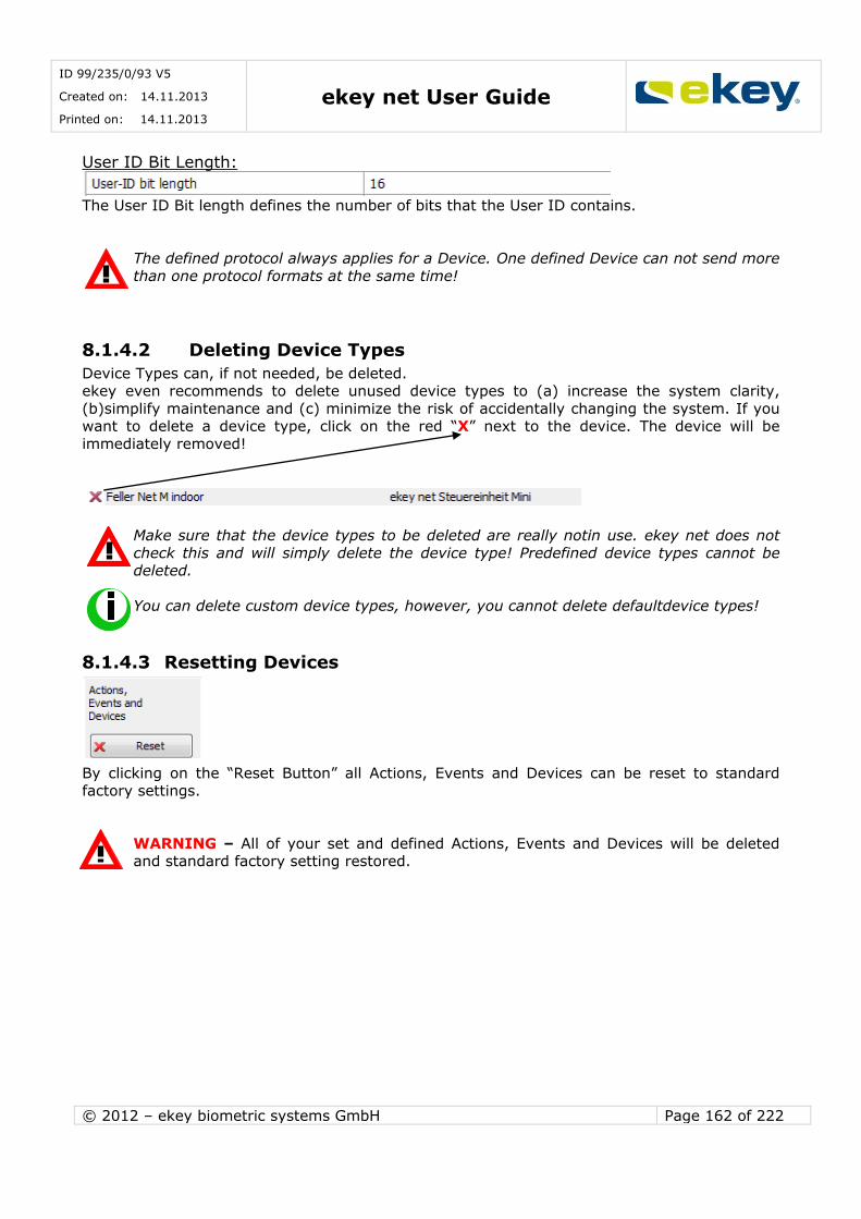
ID 99/235/0/93 V5
Created on: 14.11.2013
Printed on: 14.11.2013 ekey net User Guide
© 2012 – ekey biometric systems GmbH Page 162 of 222
User ID Bit Length:
The User ID Bit length defines the number of bits that the User ID contains.
The defined protocol always applies for a Device. One defined Device can not send more
than one protocol formats at the same time!
8.1.4.2 Deleting Device Types
Device Types can, if not needed, be deleted. ekey even recommends to delete unused device types to (a) increase the system clarity,
(b)simplify maintenance and (c) minimize the risk of accidentally changing the system. If you want to delete a device type, click on the red “X” next to the device. The device will be
immediately removed!
Make sure that the device types to be deleted are really notin use. ekey net does not
check this and will simply delete the device type! Predefined device types cannot be deleted.
You can delete custom device types, however, you cannot delete defaultdevice types!
8.1.4.3 Resetting Devices
By clicking on the “Reset Button” all Actions, Events and Devices can be reset to standard factory settings.
WARNING – All of your set and defined Actions, Events and Devices will be deleted and standard factory setting restored.

ID 99/235/0/93 V5
Created on: 14.11.2013
Printed on: 14.11.2013 ekey net User Guide
© 2012 – ekey biometric systems GmbH Page 163 of 222
8.1.5 Rights
8.1.5.1 Assigning Administrator Rights
In this tab you define which users are meant to be system administrators in ekey net, and
what rights are bound to this.
A User that is not given administrator rights in this window cannot open the ekey net
admin.
Administrator rights are fully independent of access rights!!
Administrators can, after entering their personal password and starting the ekey net Admin
program, adjust settings and parameters in the system.
BUSINESS
LIGHT COM
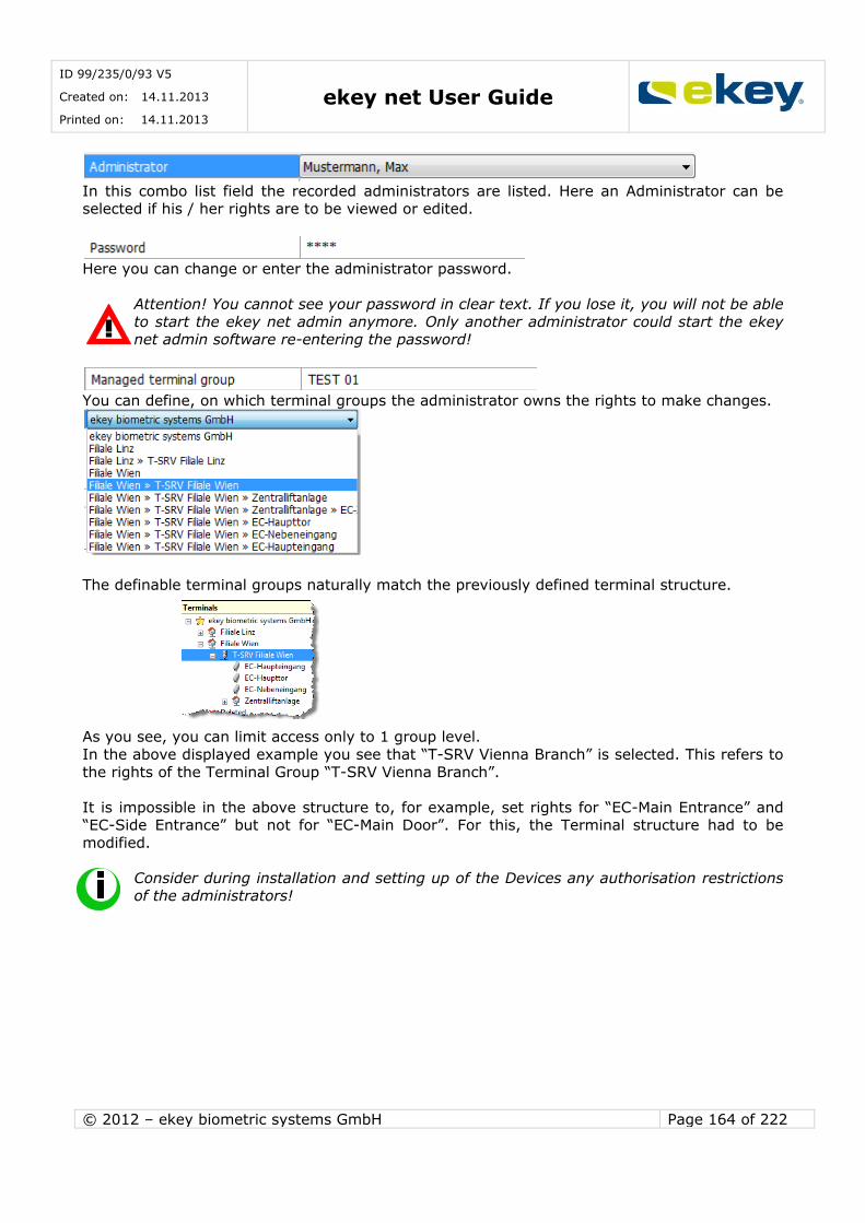
ID 99/235/0/93 V5
Created on: 14.11.2013
Printed on: 14.11.2013 ekey net User Guide
© 2012 – ekey biometric systems GmbH Page 164 of 222
In this combo list field the recorded administrators are listed. Here an Administrator can be selected if his / her rights are to be viewed or edited.
Here you can change or enter the administrator password.
Attention! You cannot see your password in clear text. If you lose it, you will not be able
to start the ekey net admin anymore. Only another administrator could start the ekey net admin software re-entering the password!
You can define, on which terminal groups the administrator owns the rights to make changes.
The definable terminal groups naturally match the previously defined terminal structure.
As you see, you can limit access only to 1 group level.
In the above displayed example you see that “T-SRV Vienna Branch” is selected. This refers to
the rights of the Terminal Group “T-SRV Vienna Branch”.
It is impossible in the above structure to, for example, set rights for “EC-Main Entrance” and “EC-Side Entrance” but not for “EC-Main Door”. For this, the Terminal structure had to be
modified.
Consider during installation and setting up of the Devices any authorisation restrictions of the administrators!
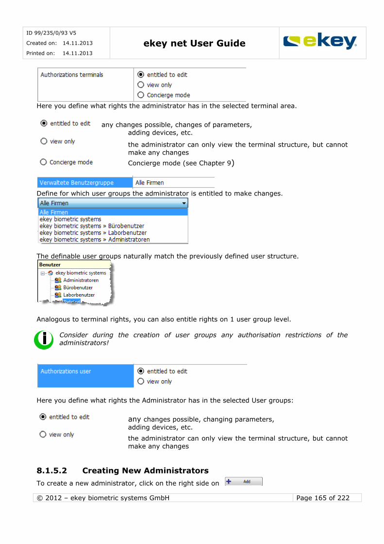
ID 99/235/0/93 V5
Created on: 14.11.2013
Printed on: 14.11.2013 ekey net User Guide
© 2012 – ekey biometric systems GmbH Page 165 of 222
Here you define what rights the administrator has in the selected terminal area.
any changes possible, changes of parameters,
adding devices, etc.
the administrator can only view the terminal structure, but cannot
make any changes
Concierge mode (see Chapter 9)
Define for which user groups the administrator is entitled to make changes.
The definable user groups naturally match the previously defined user structure.
Analogous to terminal rights, you can also entitle rights on 1 user group level.
Consider during the creation of user groups any authorisation restrictions of the administrators!
Here you define what rights the Administrator has in the selected User groups:
any changes possible, changing parameters,
adding devices, etc.
the administrator can only view the terminal structure, but cannot
make any changes
8.1.5.2 Creating New Administrators
To create a new administrator, click on the right side on
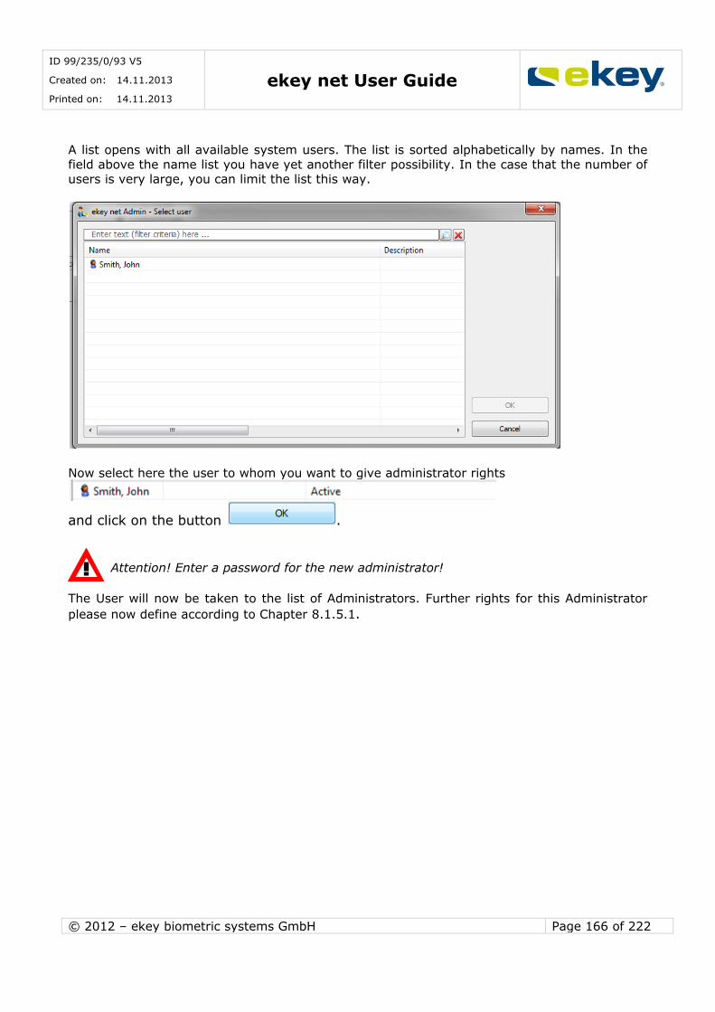
ID 99/235/0/93 V5
Created on: 14.11.2013
Printed on: 14.11.2013 ekey net User Guide
© 2012 – ekey biometric systems GmbH Page 166 of 222
A list opens with all available system users. The list is sorted alphabetically by names. In the
field above the name list you have yet another filter possibility. In the case that the number of users is very large, you can limit the list this way.
Now select here the user to whom you want to give administrator rights
and click on the button .
Attention! Enter a password for the new administrator!
The User will now be taken to the list of Administrators. Further rights for this Administrator
please now define according to Chapter 8.1.5.1.
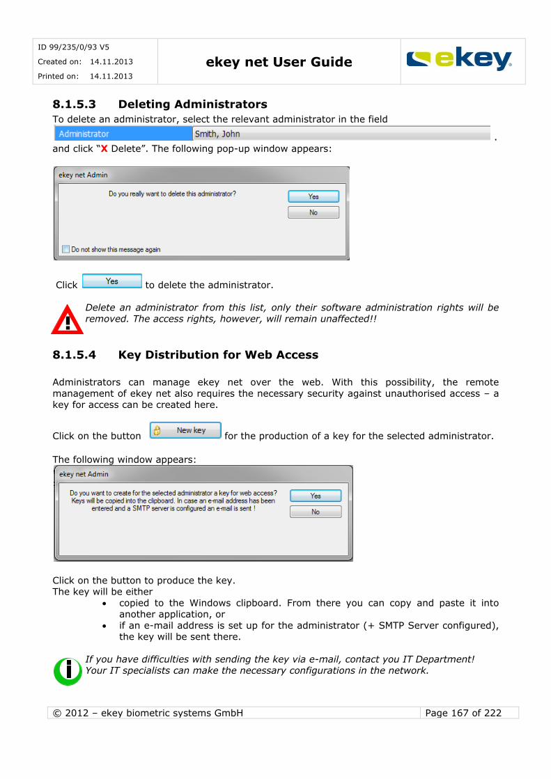
ID 99/235/0/93 V5
Created on: 14.11.2013
Printed on: 14.11.2013 ekey net User Guide
© 2012 – ekey biometric systems GmbH Page 167 of 222
8.1.5.3 Deleting Administrators
To delete an administrator, select the relevant administrator in the field
. and click “X Delete”. The following pop-up window appears:
Click to delete the administrator.
Delete an administrator from this list, only their software administration rights will be
removed. The access rights, however, will remain unaffected!!
8.1.5.4 Key Distribution for Web Access
Administrators can manage ekey net over the web. With this possibility, the remote
management of ekey net also requires the necessary security against unauthorised access – a key for access can be created here.
Click on the button for the production of a key for the selected administrator.
The following window appears:
Click on the button to produce the key. The key will be either
copied to the Windows clipboard. From there you can copy and paste it into another application, or
if an e-mail address is set up for the administrator (+ SMTP Server configured), the key will be sent there.
If you have difficulties with sending the key via e-mail, contact you IT Department! Your IT specialists can make the necessary configurations in the network.

ID 99/235/0/93 V5
Created on: 14.11.2013
Printed on: 14.11.2013 ekey net User Guide
© 2012 – ekey biometric systems GmbH Page 168 of 222
To activate the web access, you will have to click the button
A total of 16 keys in a set are given with each request. Each one of these keys can be used
once. Example of a Key Set: 28-HXVF-POML-IJMS
28-OSPQ-HTBB-PWKF
28-QTVQ-MKKV-VBFB
28-YQPO-KMEQ-RNDJ
28-UUJA-PQTL-YECP
28-GXGZ-RFPS-XKUY
28-KBAI-ZPHE-RNRB
28-ELLM-AIAN-XWFN
28-BQRI-CXTD-YPGO
28-QZIT-QDLD-UUJG
28-UEQO-GVSV-XLRJ
28-DGYX-OWAQ-EKMG
28-ICOV-HSWH-CPZY
28-GBKL-YBAZ-DOHC
28-CVOO-PZWY-TZDV
28-QCML-CHJB-HNJC
The web access function is described in detail in Chapter 11.
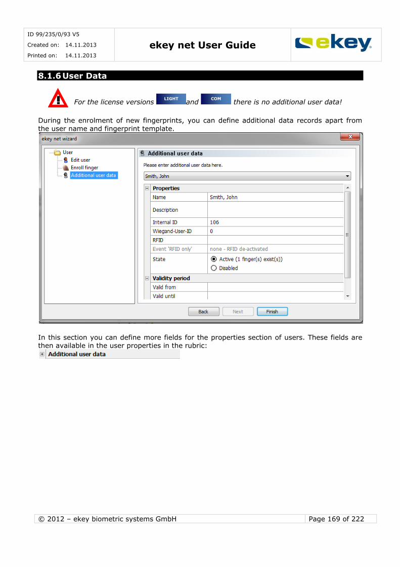
ID 99/235/0/93 V5
Created on: 14.11.2013
Printed on: 14.11.2013 ekey net User Guide
© 2012 – ekey biometric systems GmbH Page 169 of 222
8.1.6 User Data
For the license versions and there is no additional user data!
During the enrolment of new fingerprints, you can define additional data records apart from
the user name and fingerprint template.
In this section you can define more fields for the properties section of users. These fields are then available in the user properties in the rubric:
COM LIGHT
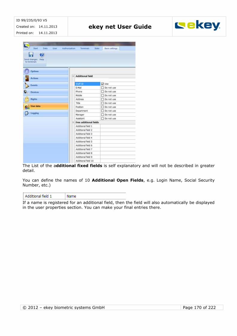
ID 99/235/0/93 V5
Created on: 14.11.2013
Printed on: 14.11.2013 ekey net User Guide
© 2012 – ekey biometric systems GmbH Page 170 of 222
The List of the additional fixed fields is self explanatory and will not be described in greater
detail.
You can define the names of 10 Additional Open Fields, e.g. Login Name, Social Security Number, etc.)
If a name is registered for an additional field, then the field will also automatically be displayed
in the user properties section. You can make your final entries there.

ID 99/235/0/93 V5
Created on: 14.11.2013
Printed on: 14.11.2013 ekey net User Guide
© 2012 – ekey biometric systems GmbH Page 171 of 222
8.1.7 Logging
For monitoring and protocol logging of the ekey net system, there are various logging
procedures available. Whether and which logging procedure to use as well as their basic settings can be defined in this tab.
In the license version you can only log positive access in a CSV file – Chapter 15.1.4
In the version the communication with other applications is in the centre of attention.
As a result, you can make all necessary adjustments for “Real Time Logging” over the HTTP protocol –simply called “Web Logging”. Details can be found in Chapter 15.1.7.
COM
LIGHT
COM
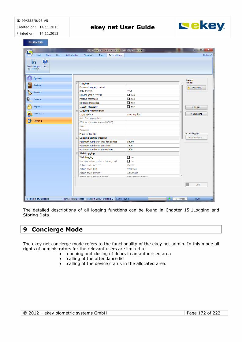
ID 99/235/0/93 V5
Created on: 14.11.2013
Printed on: 14.11.2013 ekey net User Guide
© 2012 – ekey biometric systems GmbH Page 172 of 222
The detailed descriptions of all logging functions can be found in Chapter 15.1Logging and
Storing Data.
9 Concierge Mode
The ekey net concierge mode refers to the functionality of the ekey net admin. In this mode all rights of administrators for the relevant users are limited to
opening and closing of doors in an authorised area calling of the attendance list
calling of the device status in the allocated area.
BUSINESS
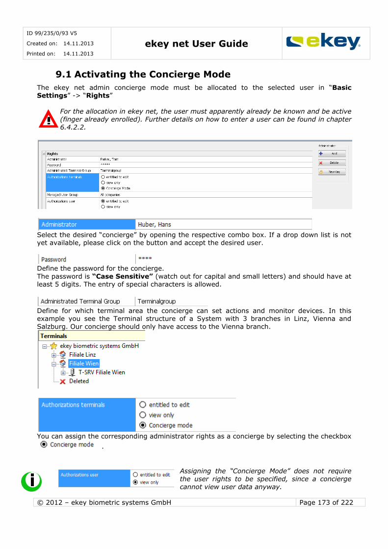
ID 99/235/0/93 V5
Created on: 14.11.2013
Printed on: 14.11.2013 ekey net User Guide
© 2012 – ekey biometric systems GmbH Page 173 of 222
9.1 Activating the Concierge Mode
The ekey net admin concierge mode must be allocated to the selected user in “Basic Settings” -> “Rights”
For the allocation in ekey net, the user must apparently already be known and be active
(finger already enrolled). Further details on how to enter a user can be found in chapter
6.4.2.2.
Select the desired “concierge” by opening the respective combo box. If a drop down list is not yet available, please click on the button and accept the desired user.
Define the password for the concierge.
The password is “Case Sensitive” (watch out for capital and small letters) and should have at least 5 digits. The entry of special characters is allowed.
Define for which terminal area the concierge can set actions and monitor devices. In this example you see the Terminal structure of a System with 3 branches in Linz, Vienna and
Salzburg. Our concierge should only have access to the Vienna branch.
You can assign the corresponding administrator rights as a concierge by selecting the checkbox
.
Assigning the “Concierge Mode” does not require
the user rights to be specified, since a concierge cannot view user data anyway.

ID 99/235/0/93 V5
Created on: 14.11.2013
Printed on: 14.11.2013 ekey net User Guide
© 2012 – ekey biometric systems GmbH Page 174 of 222
9.2 Functions in the Concierge Mode
If a concierge starts the ekey net admin using the corresponding name and password, the
concierge mode is activated automatically and minimized to the Windows tray. Click the respective icon in the Windows tray to open below written dialog:
You can trigger actions on the respective ekey net CP directly from your PC. In addition, you
can call the status of the devices in the area and check the attendance list.
9.2.1 Executing Switching Actions
To switch a relay output (e.g. to open a door) select a specific control panel and select an
action.
Click the icon to switch the relay (e.g. open the door). The action will be executed for the
selected ekey net CP. Only those control panels will be displayed that belong to the authorized
area.
Select for example the control panel Main Entrance and Impulse Switch 1.The relay output
1 will switch for 3 seconds on the ekey net CP with the name “Main Entrance”.
9.3 Device Status
The device status allows you to call the status of the terminals (finger scanner, control panel).
Click on the icon . The concierge can only see thosedevices that he/she is authorised for.
Here you can select relay 1

ID 99/235/0/93 V5
Created on: 14.11.2013
Printed on: 14.11.2013 ekey net User Guide
© 2012 – ekey biometric systems GmbH Page 175 of 222
A detailed description on the Device Status can be found in Chapter 6.7
9.4 Attendance List
The attendance list shows you the attendance of employees in the facility (organisation). By clicking on and then selecting
the window with the attendance list opens. Detailed functions on the attendance list can be
found in Chapter 10.
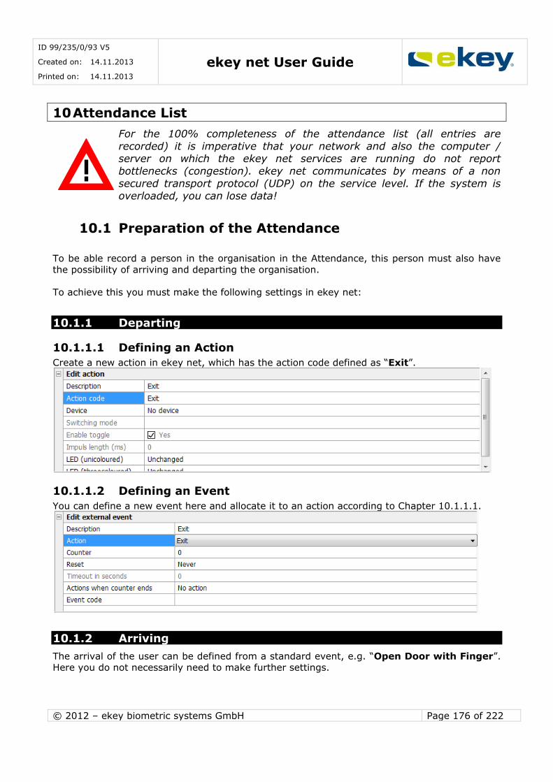
ID 99/235/0/93 V5
Created on: 14.11.2013
Printed on: 14.11.2013 ekey net User Guide
© 2012 – ekey biometric systems GmbH Page 176 of 222
10 Attendance List
For the 100% completeness of the attendance list (all entries are
recorded) it is imperative that your network and also the computer / server on which the ekey net services are running do not report
bottlenecks (congestion). ekey net communicates by means of a non
secured transport protocol (UDP) on the service level. If the system is
overloaded, you can lose data!
10.1 Preparation of the Attendance
To be able record a person in the organisation in the Attendance, this person must also have the possibility of arriving and departing the organisation.
To achieve this you must make the following settings in ekey net:
10.1.1 Departing
10.1.1.1 Defining an Action
Create a new action in ekey net, which has the action code defined as “Exit”.
10.1.1.2 Defining an Event
You can define a new event here and allocate it to an action according to Chapter 10.1.1.1.
10.1.2 Arriving
The arrival of the user can be defined from a standard event, e.g. “Open Door with Finger”. Here you do not necessarily need to make further settings.
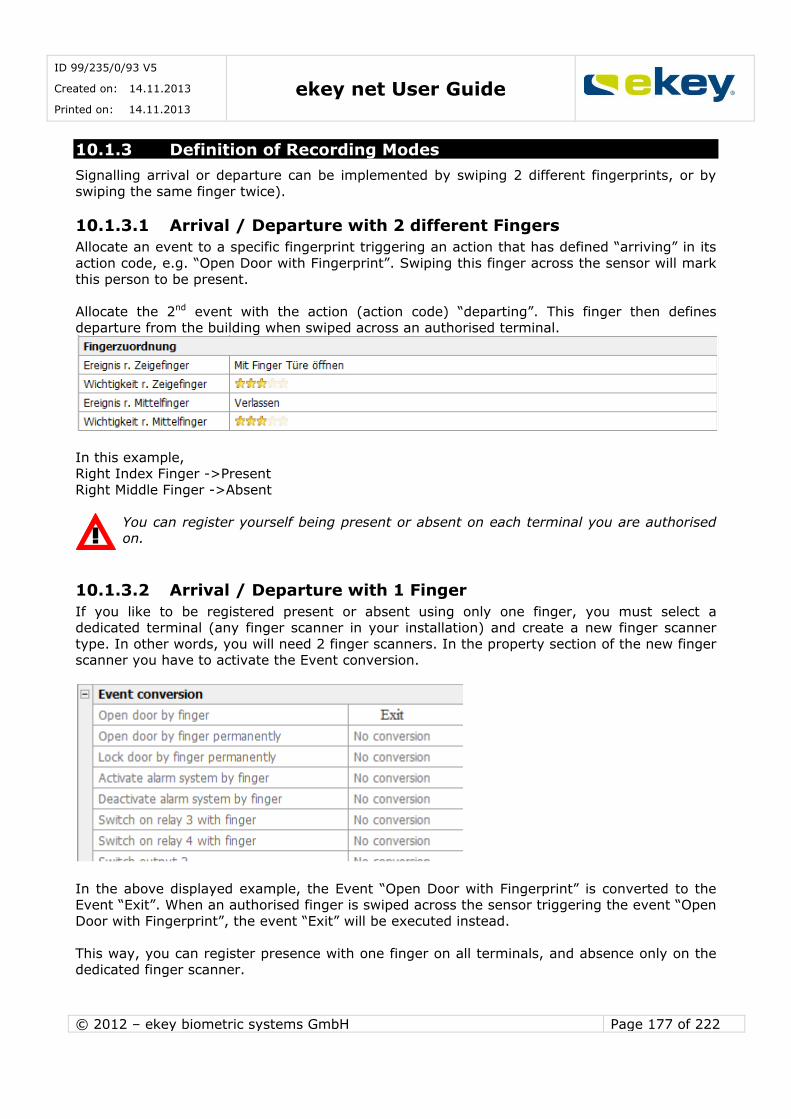
ID 99/235/0/93 V5
Created on: 14.11.2013
Printed on: 14.11.2013 ekey net User Guide
© 2012 – ekey biometric systems GmbH Page 177 of 222
10.1.3 Definition of Recording Modes
Signalling arrival or departure can be implemented by swiping 2 different fingerprints, or by
swiping the same finger twice).
10.1.3.1 Arrival / Departure with 2 different Fingers
Allocate an event to a specific fingerprint triggering an action that has defined “arriving” in its
action code, e.g. “Open Door with Fingerprint”. Swiping this finger across the sensor will mark
this person to be present.
Allocate the 2nd event with the action (action code) “departing”. This finger then defines departure from the building when swiped across an authorised terminal.
In this example, Right Index Finger ->Present
Right Middle Finger ->Absent
You can register yourself being present or absent on each terminal you are authorised on.
10.1.3.2 Arrival / Departure with 1 Finger
If you like to be registered present or absent using only one finger, you must select a dedicated terminal (any finger scanner in your installation) and create a new finger scanner
type. In other words, you will need 2 finger scanners. In the property section of the new finger scanner you have to activate the Event conversion.
In the above displayed example, the Event “Open Door with Fingerprint” is converted to the Event “Exit”. When an authorised finger is swiped across the sensor triggering the event “Open
Door with Fingerprint”, the event “Exit” will be executed instead.
This way, you can register presence with one finger on all terminals, and absence only on the
dedicated finger scanner.
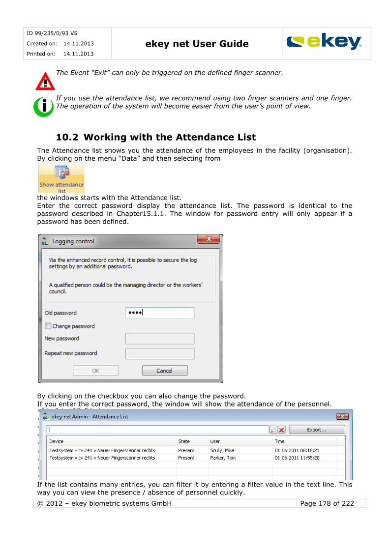
ID 99/235/0/93 V5
Created on: 14.11.2013
Printed on: 14.11.2013 ekey net User Guide
© 2012 – ekey biometric systems GmbH Page 178 of 222
The Event “Exit” can only be triggered on the defined finger scanner.
If you use the attendance list, we recommend using two finger scanners and one finger.
The operation of the system will become easier from the user’s point of view.
10.2 Working with the Attendance List
The Attendance list shows you the attendance of the employees in the facility (organisation). By clicking on the menu “Data” and then selecting from
the windows starts with the Attendance list. Enter the correct password display the attendance list. The password is identical to the
password described in Chapter15.1.1. The window for password entry will only appear if a password has been defined.
By clicking on the checkbox you can also change the password. If you enter the correct password, the window will show the attendance of the personnel.
If the list contains many entries, you can filter it by entering a filter value in the text line. This way you can view the presence / absence of personnel quickly.
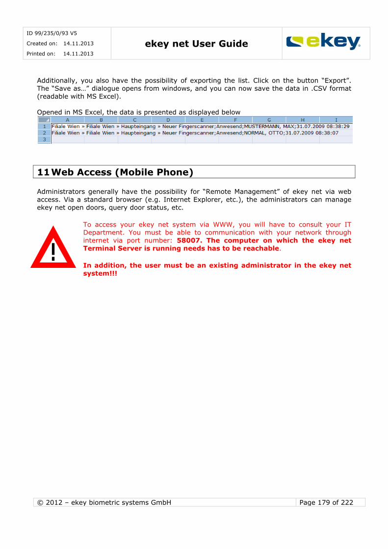
ID 99/235/0/93 V5
Created on: 14.11.2013
Printed on: 14.11.2013 ekey net User Guide
© 2012 – ekey biometric systems GmbH Page 179 of 222
Additionally, you also have the possibility of exporting the list. Click on the button “Export”. The “Save as…” dialogue opens from windows, and you can now save the data in .CSV format
(readable with MS Excel).
Opened in MS Excel, the data is presented as displayed below
11 Web Access (Mobile Phone)
Administrators generally have the possibility for “Remote Management” of ekey net via web
access. Via a standard browser (e.g. Internet Explorer, etc.), the administrators can manage
ekey net open doors, query door status, etc.
To access your ekey net system via WWW, you will have to consult your IT Department. You must be able to communication with your network through
internet via port number: 58007. The computer on which the ekey net Terminal Server is running needs has to be reachable.
In addition, the user must be an existing administrator in the ekey net
system!!!
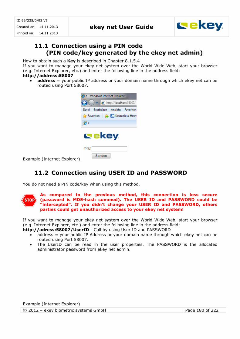
ID 99/235/0/93 V5
Created on: 14.11.2013
Printed on: 14.11.2013 ekey net User Guide
© 2012 – ekey biometric systems GmbH Page 180 of 222
11.1 Connection using a PIN code
(PIN code/key generated by the ekey net admin)
How to obtain such a Key is described in Chapter 8.1.5.4
If you want to manage your ekey net system over the World Wide Web, start your browser (e.g. Internet Explorer, etc.) and enter the following line in the address field:
http://address:58007
address = your public IP address or your domain name through which ekey net can be routed using Port 58007.
Example (Internet Explorer)
11.2 Connection using USER ID and PASSWORD
You do not need a PIN code/key when using this method.
As compared to the previous method, this connection is less secure (password is MD5-hash summed). The USER ID and PASSWORD could be
“intercepted”. If you didn’t change your USER ID and PASSWORD, others parties could get unauthorized access to your ekey net system!
If you want to manage your ekey net system over the World Wide Web, start your browser
(e.g. Internet Explorer, etc.) and enter the following line in the address field: http://adress:58007/UserID - Call by using User ID and PASSWORD
address = your public IP Address or your domain name through which ekey net can be routed using Port 58007.
The UserID can be read in the user properties. The PASSWORD is the allocated administrator password from ekey net admin.
Example (Internet Explorer)
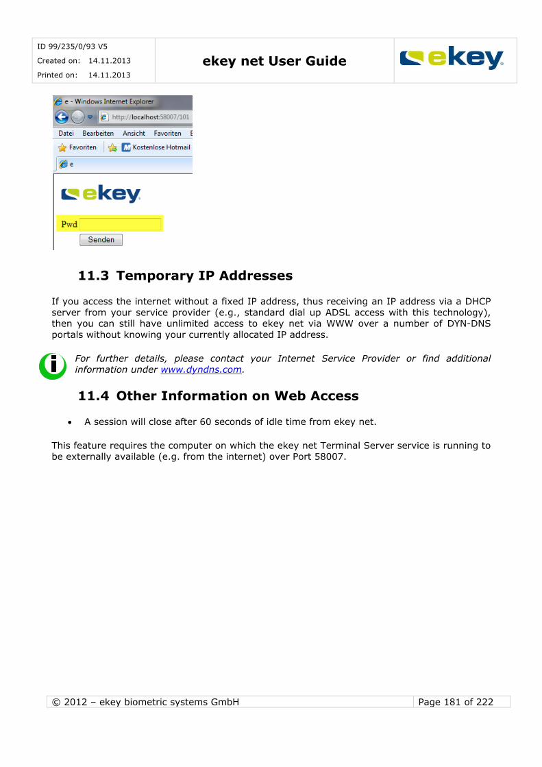
ID 99/235/0/93 V5
Created on: 14.11.2013
Printed on: 14.11.2013 ekey net User Guide
© 2012 – ekey biometric systems GmbH Page 181 of 222
11.3 Temporary IP Addresses
If you access the internet without a fixed IP address, thus receiving an IP address via a DHCP
server from your service provider (e.g., standard dial up ADSL access with this technology), then you can still have unlimited access to ekey net via WWW over a number of DYN-DNS
portals without knowing your currently allocated IP address.
For further details, please contact your Internet Service Provider or find additional information under www.dyndns.com.
11.4 Other Information on Web Access
A session will close after 60 seconds of idle time from ekey net.
This feature requires the computer on which the ekey net Terminal Server service is running to be externally available (e.g. from the internet) over Port 58007.

ID 99/235/0/93 V5
Created on: 14.11.2013
Printed on: 14.11.2013 ekey net User Guide
© 2012 – ekey biometric systems GmbH Page 182 of 222
12 ekey net Composite Control Panel
12.1 Technical Documentation
12.1.1 Wiring of the Components
By means of a so-called ekey net composite control panel, the number of switchable relays can be increased to maximum 28 relays (7 x ekey net CP DRM 4 ).
Such a composite control panel can only be made up of control panels using the same ekey net CV LAN. The maximum number of 8 devices (1 finger scanner + 7 control panels) per RS-
485-bus also applies in this case.
Either the ekey net CP mini 1 or ekey net CP mini 2 or ekey net CP DRM 4 serve as the base for the composite control panel. Those can then be extended with the required ekey net
EM mini 3 (attention: only in combination with an above-mentioned control panel!) or ekey net CP DRM 4.
Example with ekey net CP mini 2 and ekey net EM 3 - totally 20 available relays:
ekey net CV LAN
ekey net
4
1
3
2
6 5
7
8
9
10
4
1
3
2
6 5
7 8
9
10
4
1
3
2
6 5
7 8
9
10
4
1
3
2
6 5
7 8
9
10
4
1
3
2
6 5
7 8
9
10
4
1
3
2
6 5
7 8
9
10
ekey net CP MINI 2
ekey net EM
MINI 3R
ekey net EM MINI 3R
ekey net EM MINI 3R
ekey net EM
MINI 3R
ekey net EM
MINI 3R
ekey net EM
MINI 3R
6 5
7 8
9
10
4
1
3
2
ekey cable
type A
CAT5/CAT6
RELAY 1
RELAY 2
RELAY 17
RELAY 16
RELAY 15
RELAY 20
RELAY 19
RELAY 18
RELAY 10
RELAY 9
RELAY 14
RELAY 13
RELAY 12
RELAY 3
RELAY 8
RELAY 7
RELAY 6
RELAY 11
RELAY 5
RELAY 4
+8-
24VDC GND
4 white
1 green
3 brown
2yello
w
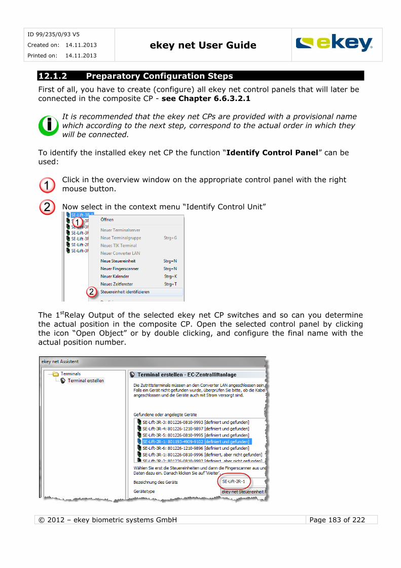
ID 99/235/0/93 V5
Created on: 14.11.2013
Printed on: 14.11.2013 ekey net User Guide
© 2012 – ekey biometric systems GmbH Page 183 of 222
12.1.2 Preparatory Configuration Steps
First of all, you have to create (configure) all ekey net control panels that will later be
connected in the composite CP - see Chapter 6.6.3.2.1
It is recommended that the ekey net CPs are provided with a provisional name which according to the next step, correspond to the actual order in which they
will be connected.
To identify the installed ekey net CP the function “Identify Control Panel” can be
used:
Click in the overview window on the appropriate control panel with the right
mouse button.
Now select in the context menu “Identify Control Unit”
The 1stRelay Output of the selected ekey net CP switches and so can you determine
the actual position in the composite CP. Open the selected control panel by clicking
the icon “Open Object” or by double clicking, and configure the final name with the
actual position number.
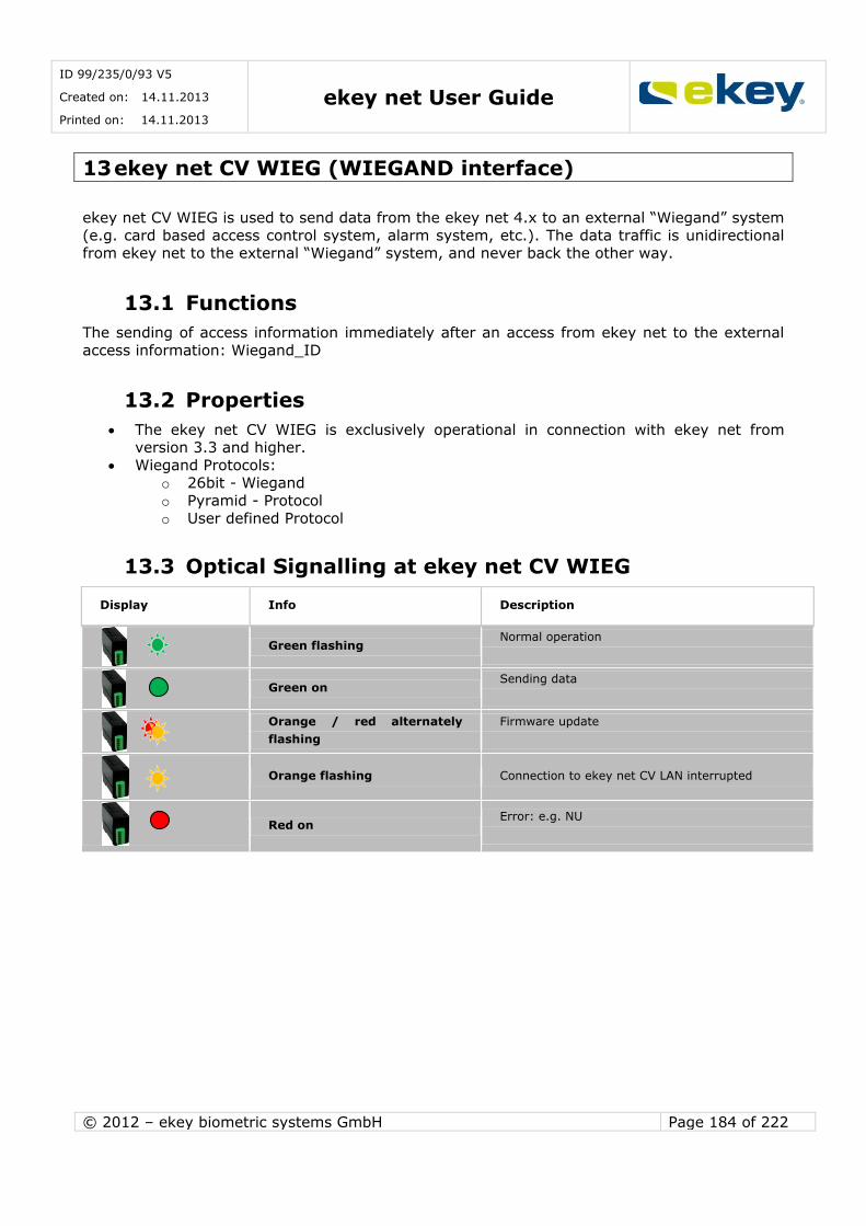
ID 99/235/0/93 V5
Created on: 14.11.2013
Printed on: 14.11.2013 ekey net User Guide
© 2012 – ekey biometric systems GmbH Page 184 of 222
13 ekey net CV WIEG (WIEGAND interface)
ekey net CV WIEG is used to send data from the ekey net 4.x to an external “Wiegand” system
(e.g. card based access control system, alarm system, etc.). The data traffic is unidirectional from ekey net to the external “Wiegand” system, and never back the other way.
13.1 Functions
The sending of access information immediately after an access from ekey net to the external
access information: Wiegand_ID
13.2 Properties
The ekey net CV WIEG is exclusively operational in connection with ekey net from version 3.3 and higher.
Wiegand Protocols: o 26bit - Wiegand
o Pyramid - Protocol
o User defined Protocol
13.3 Optical Signalling at ekey net CV WIEG
Display Info Description
Green flashing Normal operation
Green on Sending data
Orange / red alternately
flashing
Firmware update
Orange flashing Connection to ekey net CV LAN interrupted
Red on Error: e.g. NU
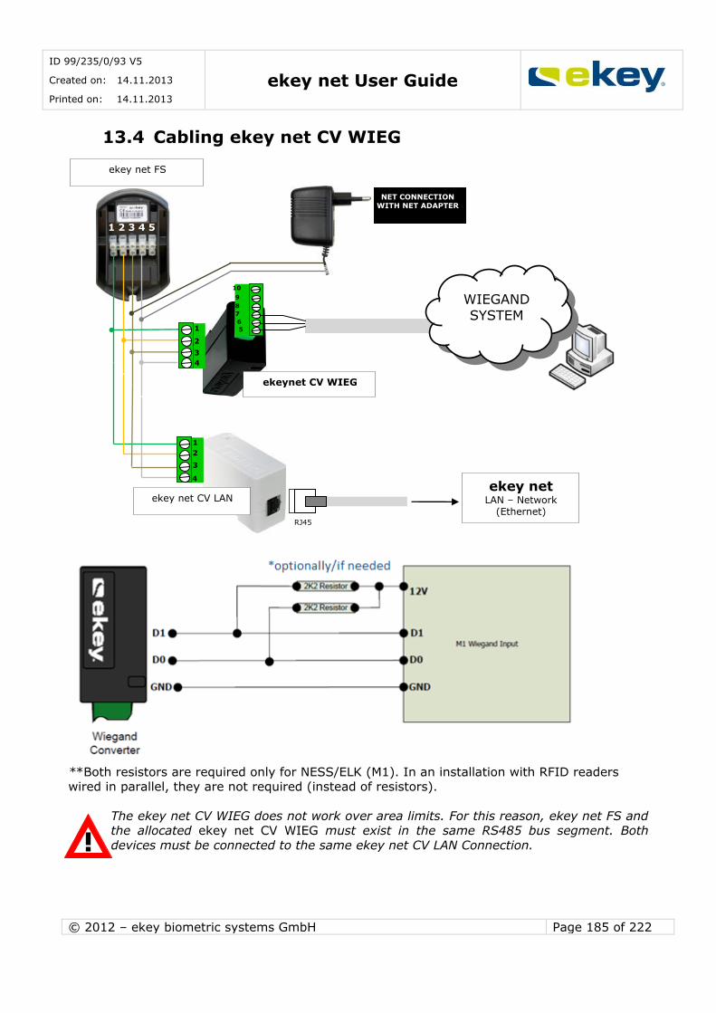
ID 99/235/0/93 V5
Created on: 14.11.2013
Printed on: 14.11.2013 ekey net User Guide
© 2012 – ekey biometric systems GmbH Page 185 of 222
13.4 Cabling ekey net CV WIEG
**Both resistors are required only for NESS/ELK (M1). In an installation with RFID readers wired in parallel, they are not required (instead of resistors).
The ekey net CV WIEG does not work over area limits. For this reason, ekey net FS and the allocated ekey net CV WIEG must exist in the same RS485 bus segment. Both
devices must be connected to the same ekey net CV LAN Connection.
ekey net FS
NET CONNECTION WITH NET ADAPTER
1 2 3 4 5
ekey net LAN – Network
(Ethernet) RJ45
ekey net CV LAN
4
1
3
2
4
1
3
2
ekeynet CV WIEG
6
5
7
8
9
10
WIEGAND SYSTEM

ID 99/235/0/93 V5
Created on: 14.11.2013
Printed on: 14.11.2013 ekey net User Guide
© 2012 – ekey biometric systems GmbH Page 186 of 222
13.5 PIN Assignment ekey net CV WIEG
PIN
No.
ekey net CV WIEG
PIN
No.
ekey net CV WIEG
1 RS485B (CL1)
5 WIEGAND D0
2 RS485A (CL2)
6 WIEGAND D1
3 -VCC (CL3) switched
7 GND
4 + VCC (CL4)
8 not used
9 not used
10 not used
You must adhere to the voltage limits (maximum ratings) as specified. The
configured device with the lowest voltage range defines the voltage limit of the power supply. However, you can also power all components separately.
4
1
3 2
6 5
7 8 9
10

ID 99/235/0/93 V5
Created on: 14.11.2013
Printed on: 14.11.2013 ekey net User Guide
© 2012 – ekey biometric systems GmbH Page 187 of 222
13.6 Activation Wiegand and Assigning Wiegand-ID in
ekey net
The configuration of ekey net CV WIEG follows in the ekey net Software from version 3.3.
13.6.1 WIEGAND- Activate Function in ekey net
To configure the Wiegand functions in ekey net, it is necessary that you have unrestricted administrator rights. Start the ekey net admin and activate under “Basic Settings” ->
“Options” -> the field “Use Wiegand ID”.
This way the Wiegand function is activated in ekey net. Next, define the Wiegand protocols to
be used.
13.6.2 Defining WIEGAND Protocol
Generally speaking, Wiegand is a fairly open protocol to transfer user specific data packets. As a result, you can define ID bit lengths as well as the total length for terminals openly within
your ekey net.
Under “Basic Settings” ->“Devices” -> you will find ekey net CV WIEG. In the device view you can find a predefined ekey net CV WIEG with the Standard 26bit-
Protocol. Total length = 26 (including Start & Stop bits)
Finger scanner ID bit length = 8
User ID bit length = 16

ID 99/235/0/93 V5
Created on: 14.11.2013
Printed on: 14.11.2013 ekey net User Guide
© 2012 – ekey biometric systems GmbH Page 188 of 222
If your system does not work with the standard configuration and requires different bit
lengths, you can create a user defined ekey net CV WIEG by clicking on the button “Click here for a new entry”.
Apart from the 26 bit Standard Wiegand protocol, there are 2otherpossibilities to definethe
protocol (please click into the entry field “Protocol” under “Wiegand Options”):
Pyramid: 39 bit protocol User defined: You can define an ID Bit length in any way.
Total Bit Length Equivalent to the added number of bits from the OEM ID, Finger Scanner ID and User ID plus 2
(Start + Stop bits) OEM ID Bit Length
Equivalent to the bit length of the OEM identification (= Company_ID). The OEM identification will be used for the construction inter-organisational systems.
The IDs will differ depending on the organisation that the Wiegand package came from.
Finger Scanner ID Length (Device ID)
The finger scanner ID Length corresponds to the device ID and is to be entered with the properties of the allocated finger scanners.
User ID Length
Equivalent to the number of bits of the user ID. To be entered in user section.
13.6.3 Entering Individual ID
Enter the ID as a decimal value. If the converted decimal value of the binary value exceeds the bit length, the
excess bits on the MSB side are truncated.

ID 99/235/0/93 V5
Created on: 14.11.2013
Printed on: 14.11.2013 ekey net User Guide
© 2012 – ekey biometric systems GmbH Page 189 of 222
Example 1 (correct entry): e.g. USER ID = 130, FINGERSCANNER ID = 98
Standard Protocol 26 bit: Finger Scanner ID Bit length = 8 User ID Bit length =16
Finger Scanner ID Bit 2 = MSB User ID Bit 10 = MSB
PE…. Even parity for Bit 2-13
PO … Odd parity for Bit 14-25
Gesendeter Bitstream an Wiegand-System:
Example 2 (incorrect entry):
ATTENTION! A false ID will be sent in this example!!!
ekey net does not check the entered ID against the total bit length.
User ID 137 Finger Scanner ID = 276 Standard Protocol 26 bit:
Finger Scanner ID Bit length= 8
UserID Bit length =16 Finger Scanner ID Bit 2 = MSB
User ID Bit 10 = MSB PE…. Even parity for Bit 2-13
PO … Odd parity for Bit 14-25
Sent bit stream to Wiegand system
ID PE FINGERSCANNER ID USER ID PO
BitN° 1 2 3 4 5 6 7 8 9 10 11 12 13 14 15 16 17 18 19 20 20 22 23 24 25 26
Contents 1 0 0 0 1 0 1 0 0 0 0 0 0 0 0 0 0 1 0 0 0 1 0 0 1 0
With regard to the finger scanner ID, the first bit from 276 = 1 0001 0100 will be truncated
and only sent as ID 20!!!
When entering an ID, it is therefore important to take the bit length into account. ekey net does not check this !!
13.6.4 Entering User ID
Under “User” the appropriate recorded user is to be selected and under “Additional User Data”, the “Wiegand User ID” has to be entered as a decimal value.
Pay attention to the correct bit length!! (See “Entering Individual ID”). The User ID can, for example, be identical with a Wiegand Card Number of an external system.
ID PE FINGERSCANNER ID USER ID PO
BitN° 1 2 3 4 5 6 7 8 9 10 11 12 13 14 15 16 17 18 19 20 20 22 23 24 25 26
Contents 1 0 1 1 0 0 0 1 0 0 0 0 0 0 0 0 0 1 0 0 0 0 0 1 0 1

ID 99/235/0/93 V5
Created on: 14.11.2013
Printed on: 14.11.2013 ekey net User Guide
© 2012 – ekey biometric systems GmbH Page 190 of 222
13.6.5 Entering Finger Scanner ID
Select the finger scanner under terminals, which should send the identification data to the
Wiegand System. Enter the “Wiegand ID” (= Finger Scanner ID as a decimal value) by clicking the “Edit Finger Scanner” button and define under “Assigned Control Panels” the
corresponding ekey CV WIEG. Pay attention to the correct bit length!! (See “Entering Individual ID”).
Parity Bits (first and last bit of Wiegand data packets) are automatically calculated
by ekey net and are not taken into account with the entry of the ID’s !

ID 99/235/0/93 V5
Created on: 14.11.2013
Printed on: 14.11.2013 ekey net User Guide
© 2012 – ekey biometric systems GmbH Page 191 of 222
13.7 Technical Data (maximum ratings)
General Data (MAXIMUM Ratings) Technical Data
ekey net CV WIEG
Unit Value
Supply
VAC 8-24
VDC 8-30
Power consumption W ca.1
Temperature range °C -20 bis +70
Protection IP20
Voltage limits D0, D1, LED1 and LED2
D0 and D1 are open collector outputs. The appropriate load of the Master System (remote) must be adjusted accordingly.
Value Unit min max
VoL (Output Low) V 4.0 5.5
Voh (Output High) V 0.0 1.0
Iol (Current output low) mA -1.0 0.0
Ioh (Current output high) mA -25.0 0.0
Waveform at D0 and D1
Symbol Description Unit Time
min Type ma
x
Tpw Time Pulse width µs 20 30 100
Tpi Time Pulse interval ms 1 2 20
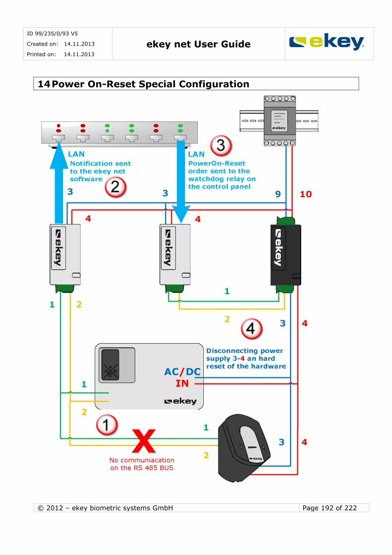
ID 99/235/0/93 V5
Created on: 14.11.2013
Printed on: 14.11.2013 ekey net User Guide
© 2012 – ekey biometric systems GmbH Page 192 of 222
14 Power On-Reset Special Configuration

ID 99/235/0/93 V5
Created on: 14.11.2013
Printed on: 14.11.2013 ekey net User Guide
© 2012 – ekey biometric systems GmbH Page 193 of 222
15 Data Logging
To guarantee the integrity of the log files (i.e. all events recorded), it is vital that neither your network (Ethernet) nor the computers / servers on
which the ekey net services have been installed face any bottlenecks.
ekey net uses a communication protocol that does not control data
transfer (UDP). If not enough resources are available, data could be lost!
15.1 Recording and Saving Log Files
ekey net offers the following options for saving system data (logs) which occur during
operation:
Logging in CSV-format (ASCII or UNICODE) ekey reporting (reports directly in the ekey software, requires ODBC/SQL server)
ODBC/SQL logging for 3rdparty software export WEB logging (via html links e.g. for print server/printing solutions)
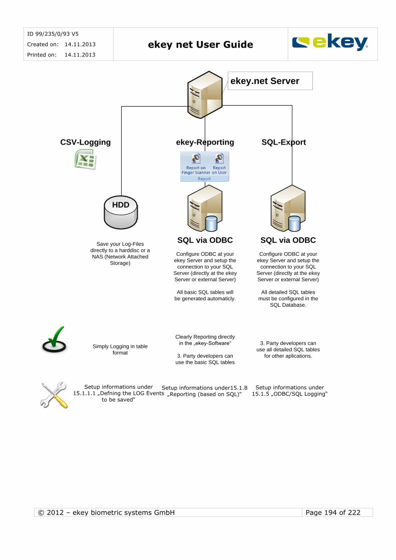
ID 99/235/0/93 V5
Created on: 14.11.2013
Printed on: 14.11.2013 ekey net User Guide
© 2012 – ekey biometric systems GmbH Page 194 of 222
ekey.net Server
CSV-Logging ekey-Reporting
SQL via ODBC
SQL-Export
SQL via ODBCSave your Log-Files
directly to a harddisc or a
NAS (Network Attached
Storage)
Configure ODBC at your
ekey Server and setup the
connection to your SQL
Server (directly at the ekey
Server or external Server)
All basic SQL tables will
be generated automaticly.
Configure ODBC at your
ekey Server and setup the
connection to your SQL
Server (directly at the ekey
Server or external Server)
All detailed SQL tables
must be configured in the
SQL Database.
Simply Logging in table
format
Clearly Reporting directly
in the „ekey-Software“
3. Party developers can
use the basic SQL tables
3. Party developers can
use all detailed SQL tables
for other aplications.
Setup informations under15.1.8 „Reporting (based on SQL)“
Setup informations under15.1.1.1 „Defning the LOG Events
to be saved“
Setup informations under15.1.5 „ODBC/SQL Logging“
HDD
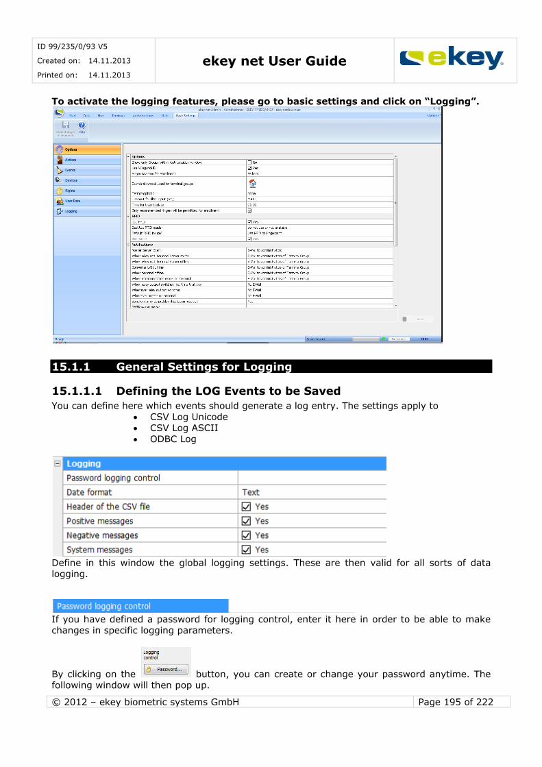
ID 99/235/0/93 V5
Created on: 14.11.2013
Printed on: 14.11.2013 ekey net User Guide
© 2012 – ekey biometric systems GmbH Page 195 of 222
To activate the logging features, please go to basic settings and click on “Logging”.
15.1.1 General Settings for Logging
15.1.1.1 Defining the LOG Events to be Saved
You can define here which events should generate a log entry. The settings apply to
CSV Log Unicode CSV Log ASCII
ODBC Log
Define in this window the global logging settings. These are then valid for all sorts of data logging.
If you have defined a password for logging control, enter it here in order to be able to make
changes in specific logging parameters.
By clicking on the button, you can create or change your password anytime. The following window will then pop up.
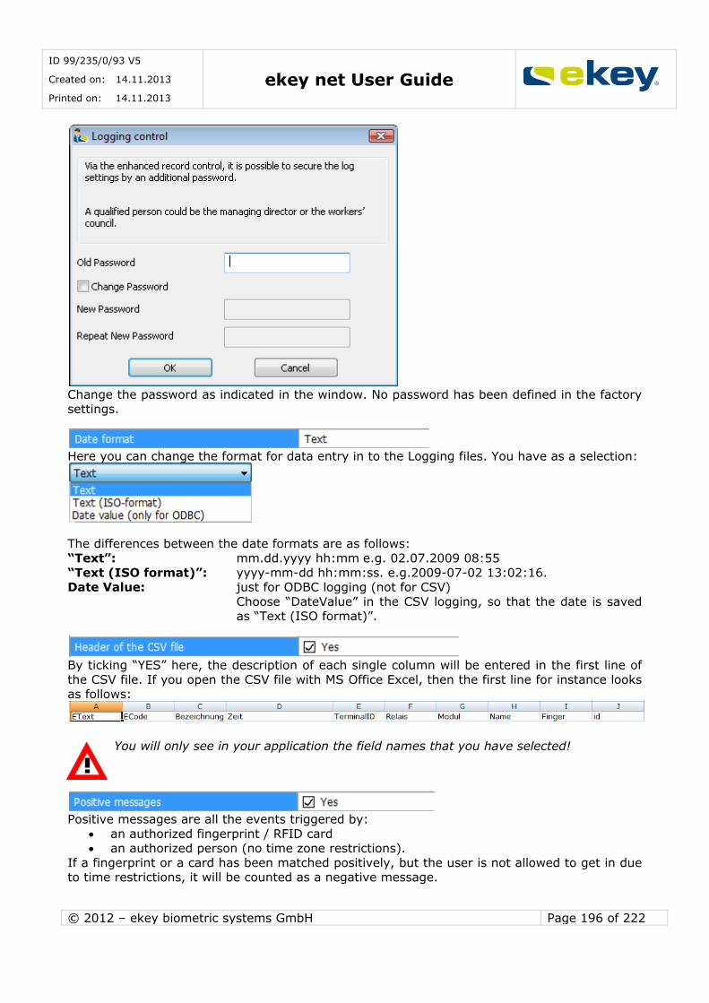
ID 99/235/0/93 V5
Created on: 14.11.2013
Printed on: 14.11.2013 ekey net User Guide
© 2012 – ekey biometric systems GmbH Page 196 of 222
Change the password as indicated in the window. No password has been defined in the factory settings.
Here you can change the format for data entry in to the Logging files. You have as a selection:
The differences between the date formats are as follows:
“Text”: mm.dd.yyyy hh:mm e.g. 02.07.2009 08:55
“Text (ISO format)”: yyyy-mm-dd hh:mm:ss. e.g.2009-07-02 13:02:16. Date Value: just for ODBC logging (not for CSV)
Choose “DateValue” in the CSV logging, so that the date is saved as “Text (ISO format)”.
By ticking “YES” here, the description of each single column will be entered in the first line of
the CSV file. If you open the CSV file with MS Office Excel, then the first line for instance looks as follows:
You will only see in your application the field names that you have selected!
Positive messages are all the events triggered by:
an authorized fingerprint / RFID card an authorized person (no time zone restrictions).
If a fingerprint or a card has been matched positively, but the user is not allowed to get in due to time restrictions, it will be counted as a negative message.

ID 99/235/0/93 V5
Created on: 14.11.2013
Printed on: 14.11.2013 ekey net User Guide
© 2012 – ekey biometric systems GmbH Page 197 of 222
If you tick YES here, then all these positive events will be recorded into the log file.
Negative messages are all the events triggered by:
an unauthorized fingerprint / RFID card rejection due to time zone / calendar restrictions.
You can decide here if these events should be recorded in the log file.
System messages are events carried out by the ekey net system automatically, without any user entries (except for the ekey net Admin logon) such as:
Learning finger Admin Logon
Data update on a device
connected / not connected You can decide here if these system messages should be recorded in the log file.
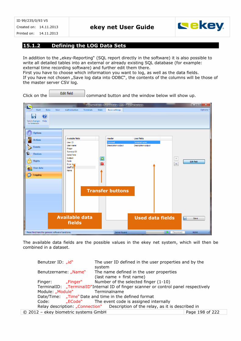
ID 99/235/0/93 V5
Created on: 14.11.2013
Printed on: 14.11.2013 ekey net User Guide
© 2012 – ekey biometric systems GmbH Page 198 of 222
15.1.2 Defining the LOG Data Sets
In addition to the „ekey-Reporting“ (SQL report directly in the software) it is also possible to write all detailed tables into an external or already existing SQL database (for example:
external time recording software) and further edit them there. First you have to choose which information you want to log, as well as the data fields.
If you have not chosen „Save log data into ODBC“, the contents of the columns will be those of the master server CSV log.
Click on the command button and the window below will show up.
The available data fields are the possible values in the ekey net system, which will then be
combined in a dataset.
Benutzer ID: „id“ The user ID defined in the user properties and by the
system
Benutzername: „Name“ The name defined in the user properties (last name + first name)
Finger: „Finger“ Number of the selected finger (1-10) TerminalID: „TerminalID“Internal ID of finger scanner or control panel respectively
Module: „Module“ Terminalname Date/Time: „Time“ Date and time in the defined format
Code: „ECode“ The event code is assigned internally Relay description: „Connection“ Description of the relay, as it is described in
Available data fields
Used data fields
Transfer buttons
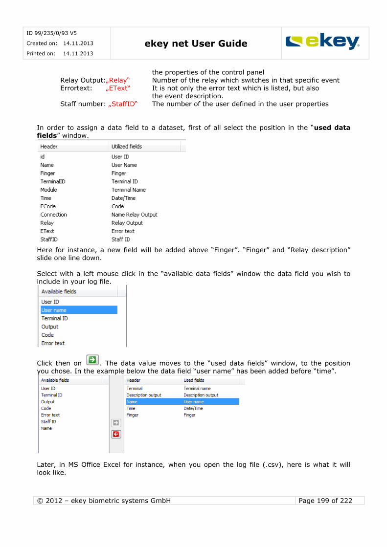
ID 99/235/0/93 V5
Created on: 14.11.2013
Printed on: 14.11.2013 ekey net User Guide
© 2012 – ekey biometric systems GmbH Page 199 of 222
the properties of the control panel
Relay Output:„Relay“ Number of the relay which switches in that specific event Errortext: „EText“ It is not only the error text which is listed, but also
the event description. Staff number: „StaffID“ The number of the user defined in the user properties
In order to assign a data field to a dataset, first of all select the position in the “used data
fields” window.
Here for instance, a new field will be added above “Finger”. “Finger” and “Relay description”
slide one line down.
Select with a left mouse click in the “available data fields” window the data field you wish to include in your log file.
Click then on . The data value moves to the “used data fields” window, to the position you chose. In the example below the data field “user name” has been added before “time”.
Later, in MS Office Excel for instance, when you open the log file (.csv), here is what it will
look like.

ID 99/235/0/93 V5
Created on: 14.11.2013
Printed on: 14.11.2013 ekey net User Guide
© 2012 – ekey biometric systems GmbH Page 200 of 222
If you change the order of the data fields in an already existing log file (.csv), then the
already existing entries will not be changed! The data fields sequence stays as it has
been defined before. All the new entries will be arranged in the new sequence which has been defined. Therefore, if you change your datasets, always create a new log file!
15.1.3 Logging Master Server
Log data will be collected here from the entire ekey net structure
Beware when using the “Log for Time Attendance” feature: if a personnel number has been
assigned to the user, then this personnel number will be displayed in the log instead of the user´s name.
You can make the following configurations.
Here select the type of logging
Do not save log data: No log data is saved. Save log data: Log data is saved, but in ekey internal Format. The data can then be called in
the data window. No path to be entered. Save log data in a CSV Text file (Unicode):The log data will be saved in a .csv file in
UNICODE Format.
Save log data in a CSV Text file (ASCII):The log data will be saved in a .csv file in ASCII format.
Save log data in ODBC: The log data will be saved in a database using ODBC (see ODBC Logging Chapter 15.1.5).
If you have selected one out of the two types of CSV logging, then enter a path here including
file name and file extension. Make sure that you have read/write permissions on the location the file is to be saved.
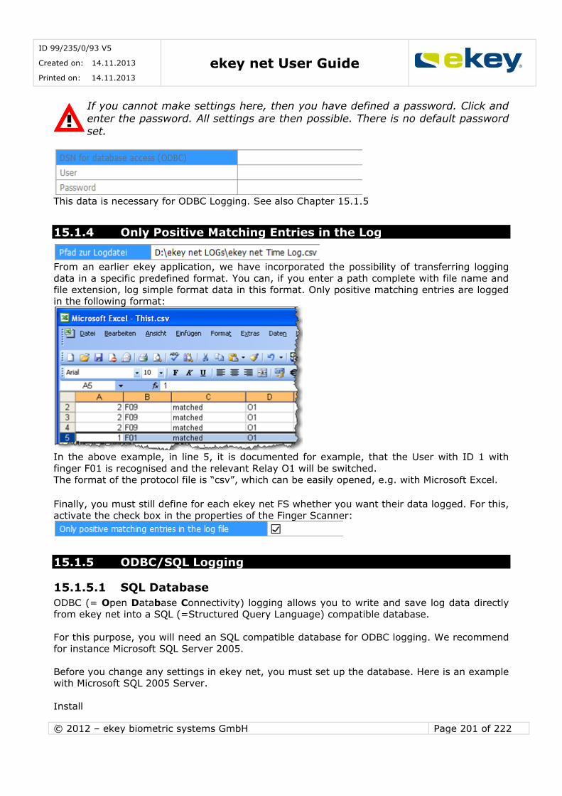
ID 99/235/0/93 V5
Created on: 14.11.2013
Printed on: 14.11.2013 ekey net User Guide
© 2012 – ekey biometric systems GmbH Page 201 of 222
If you cannot make settings here, then you have defined a password. Click and
enter the password. All settings are then possible. There is no default password
set.
This data is necessary for ODBC Logging. See also Chapter 15.1.5
15.1.4 Only Positive Matching Entries in the Log
From an earlier ekey application, we have incorporated the possibility of transferring logging
data in a specific predefined format. You can, if you enter a path complete with file name and file extension, log simple format data in this format. Only positive matching entries are logged
in the following format:
In the above example, in line 5, it is documented for example, that the User with ID 1 with
finger F01 is recognised and the relevant Relay O1 will be switched. The format of the protocol file is “csv”, which can be easily opened, e.g. with Microsoft Excel.
Finally, you must still define for each ekey net FS whether you want their data logged. For this, activate the check box in the properties of the Finger Scanner:
15.1.5 ODBC/SQL Logging
15.1.5.1 SQL Database
ODBC (= Open Database Connectivity) logging allows you to write and save log data directly from ekey net into a SQL (=Structured Query Language) compatible database.
For this purpose, you will need an SQL compatible database for ODBC logging. We recommend
for instance Microsoft SQL Server 2005.
Before you change any settings in ekey net, you must set up the database. Here is an example with Microsoft SQL 2005 Server.
Install
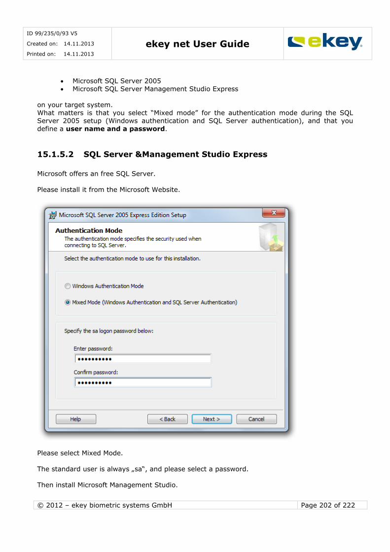
ID 99/235/0/93 V5
Created on: 14.11.2013
Printed on: 14.11.2013 ekey net User Guide
© 2012 – ekey biometric systems GmbH Page 202 of 222
Microsoft SQL Server 2005 Microsoft SQL Server Management Studio Express
on your target system.
What matters is that you select “Mixed mode” for the authentication mode during the SQL Server 2005 setup (Windows authentication and SQL Server authentication), and that you
define a user name and a password.
15.1.5.2 SQL Server &Management Studio Express
Microsoft offers an free SQL Server.
Please install it from the Microsoft Website.
Please select Mixed Mode.
The standard user is always „sa“, and please select a password.
Then install Microsoft Management Studio.
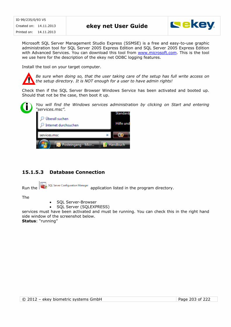
ID 99/235/0/93 V5
Created on: 14.11.2013
Printed on: 14.11.2013 ekey net User Guide
© 2012 – ekey biometric systems GmbH Page 203 of 222
Microsoft SQL Server Management Studio Express (SSMSE) is a free and easy-to-use graphic
administration tool for SQL Server 2005 Express Edition and SQL Server 2005 Express Edition with Advanced Services. You can download this tool from www.microsoft.com. This is the tool
we use here for the description of the ekey net ODBC logging features.
Install the tool on your target computer.
Be sure when doing so, that the user taking care of the setup has full write access on
the setup directory. It is NOT enough for a user to have admin rights!
Check then if the SQL Server Browser Windows Service has been activated and booted up. Should that not be the case, then boot it up.
You will find the Windows services administration by clicking on Start and entering
“services.msc”.
15.1.5.3 Database Connection
Run the application listed in the program directory.
The
SQL Server-Browser SQL Server (SQLEXPRESS)
services must have been activated and must be running. You can check this in the right hand
side window of the screenshot below. Status: “running”
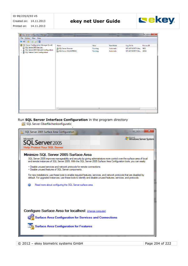
ID 99/235/0/93 V5
Created on: 14.11.2013
Printed on: 14.11.2013 ekey net User Guide
© 2012 – ekey biometric systems GmbH Page 204 of 222
Run SQL Server Interface Configuration in the program directory
.
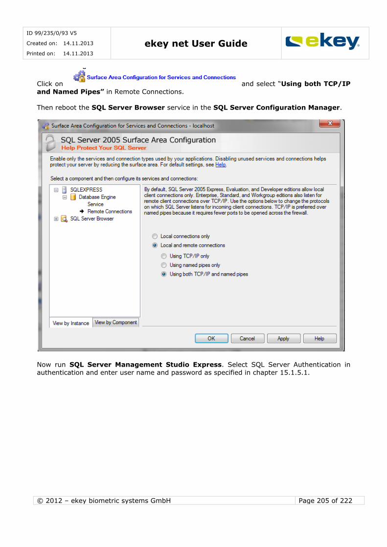
ID 99/235/0/93 V5
Created on: 14.11.2013
Printed on: 14.11.2013 ekey net User Guide
© 2012 – ekey biometric systems GmbH Page 205 of 222
Click on and select “Using both TCP/IP
and Named Pipes” in Remote Connections.
Then reboot the SQL Server Browser service in the SQL Server Configuration Manager.
Now run SQL Server Management Studio Express. Select SQL Server Authentication in
authentication and enter user name and password as specified in chapter 15.1.5.1.
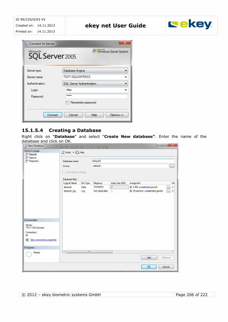
ID 99/235/0/93 V5
Created on: 14.11.2013
Printed on: 14.11.2013 ekey net User Guide
© 2012 – ekey biometric systems GmbH Page 206 of 222
15.1.5.4 Creating a Database
Right click on “Database” and select “Create New database”. Enter the name of the
database and click on OK.
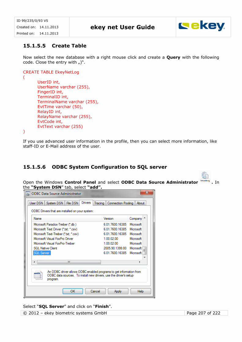
ID 99/235/0/93 V5
Created on: 14.11.2013
Printed on: 14.11.2013 ekey net User Guide
© 2012 – ekey biometric systems GmbH Page 207 of 222
15.1.5.5 Create Table
Now select the new database with a right mouse click and create a Query with the following code. Close the entry with „)“.
CREATE TABLE EkeyNetLog
(
UserID int, UserName varchar (255),
FingerID int, TerminalID int,
TerminalName varchar (255), EvtTime varchar (50),
RelayID int, RelayName varchar (255),
EvtCode int,
EvtText varchar (255) )
If you use advanced user information in the profile, then you can select more information, like
staff-ID or E-Mail address of the user.
15.1.5.6 ODBC System Configuration to SQL server
Open the Windows Control Panel and select ODBC Data Source Administrator . In
the “System DSN” tab, select “add”.
Select “SQL Server” and click on “Finish”.

ID 99/235/0/93 V5
Created on: 14.11.2013
Printed on: 14.11.2013 ekey net User Guide
© 2012 – ekey biometric systems GmbH Page 208 of 222
Enter the database name (= this name is then the one to be used in ekey net admin!)
and under Server “Host name”\SQLEXPRESS. Click on “Next>“.
Select “With SQL Server Authentication…..” and fill out the user name and password fields as specified in 15.1.5.1. Click on “Next>“.
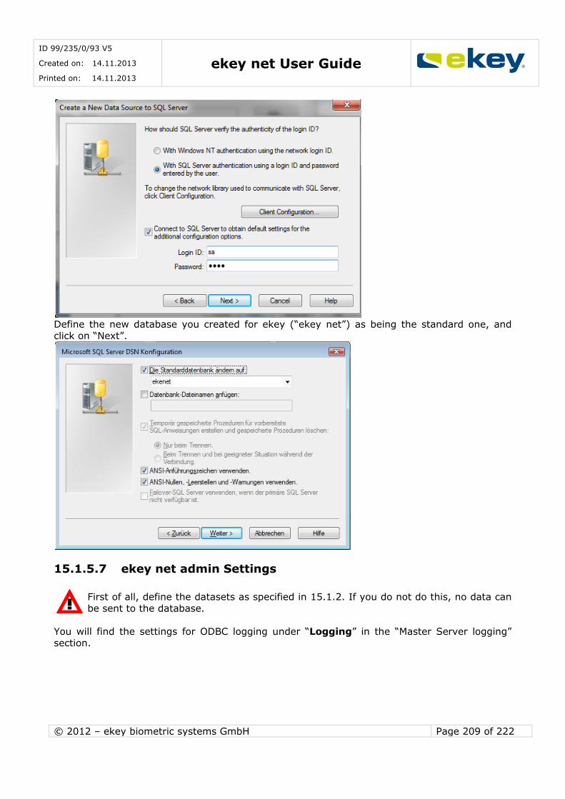
ID 99/235/0/93 V5
Created on: 14.11.2013
Printed on: 14.11.2013 ekey net User Guide
© 2012 – ekey biometric systems GmbH Page 209 of 222
Define the new database you created for ekey (“ekey net”) as being the standard one, and click on “Next”.
15.1.5.7 ekey net admin Settings
First of all, define the datasets as specified in 15.1.2. If you do not do this, no data can
be sent to the database.
You will find the settings for ODBC logging under “Logging” in the “Master Server logging” section.
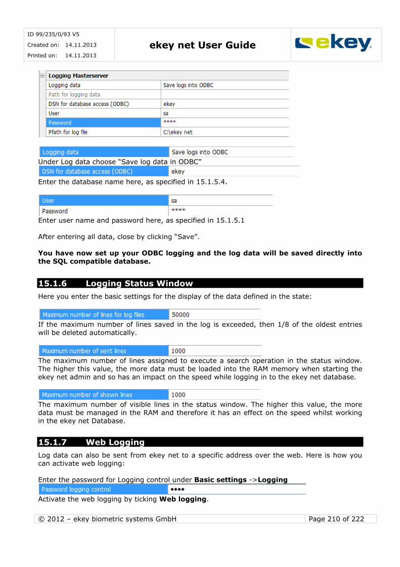
ID 99/235/0/93 V5
Created on: 14.11.2013
Printed on: 14.11.2013 ekey net User Guide
© 2012 – ekey biometric systems GmbH Page 210 of 222
Under Log data choose “Save log data in ODBC”
Enter the database name here, as specified in 15.1.5.4.
Enter user name and password here, as specified in 15.1.5.1
After entering all data, close by clicking “Save”.
You have now set up your ODBC logging and the log data will be saved directly into
the SQL compatible database.
15.1.6 Logging Status Window
Here you enter the basic settings for the display of the data defined in the state:
If the maximum number of lines saved in the log is exceeded, then 1/8 of the oldest entries
will be deleted automatically.
The maximum number of lines assigned to execute a search operation in the status window.
The higher this value, the more data must be loaded into the RAM memory when starting the ekey net admin and so has an impact on the speed while logging in to the ekey net database.
The maximum number of visible lines in the status window. The higher this value, the more
data must be managed in the RAM and therefore it has an effect on the speed whilst working in the ekey net Database.
15.1.7 Web Logging
Log data can also be sent from ekey net to a specific address over the web. Here is how you can activate web logging:
Enter the password for Logging control under Basic settings ->Logging
Activate the web logging by ticking Web logging.
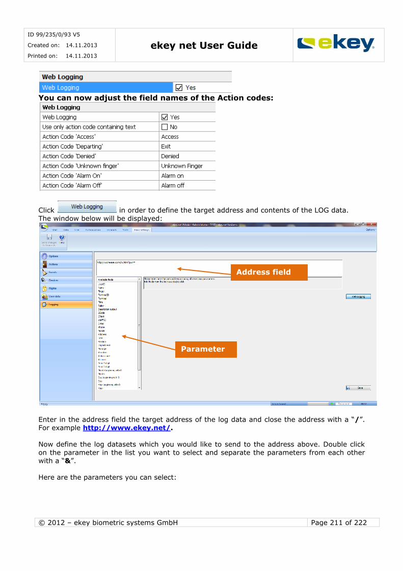
ID 99/235/0/93 V5
Created on: 14.11.2013
Printed on: 14.11.2013 ekey net User Guide
© 2012 – ekey biometric systems GmbH Page 211 of 222
You can now adjust the field names of the Action codes:
Click in order to define the target address and contents of the LOG data.
The window below will be displayed:
Enter in the address field the target address of the log data and close the address with a “/”.
For example http://www.ekey.net/.
Now define the log datasets which you would like to send to the address above. Double click
on the parameter in the list you want to select and separate the parameters from each other with a “&”.
Here are the parameters you can select:
Parameter
Address field
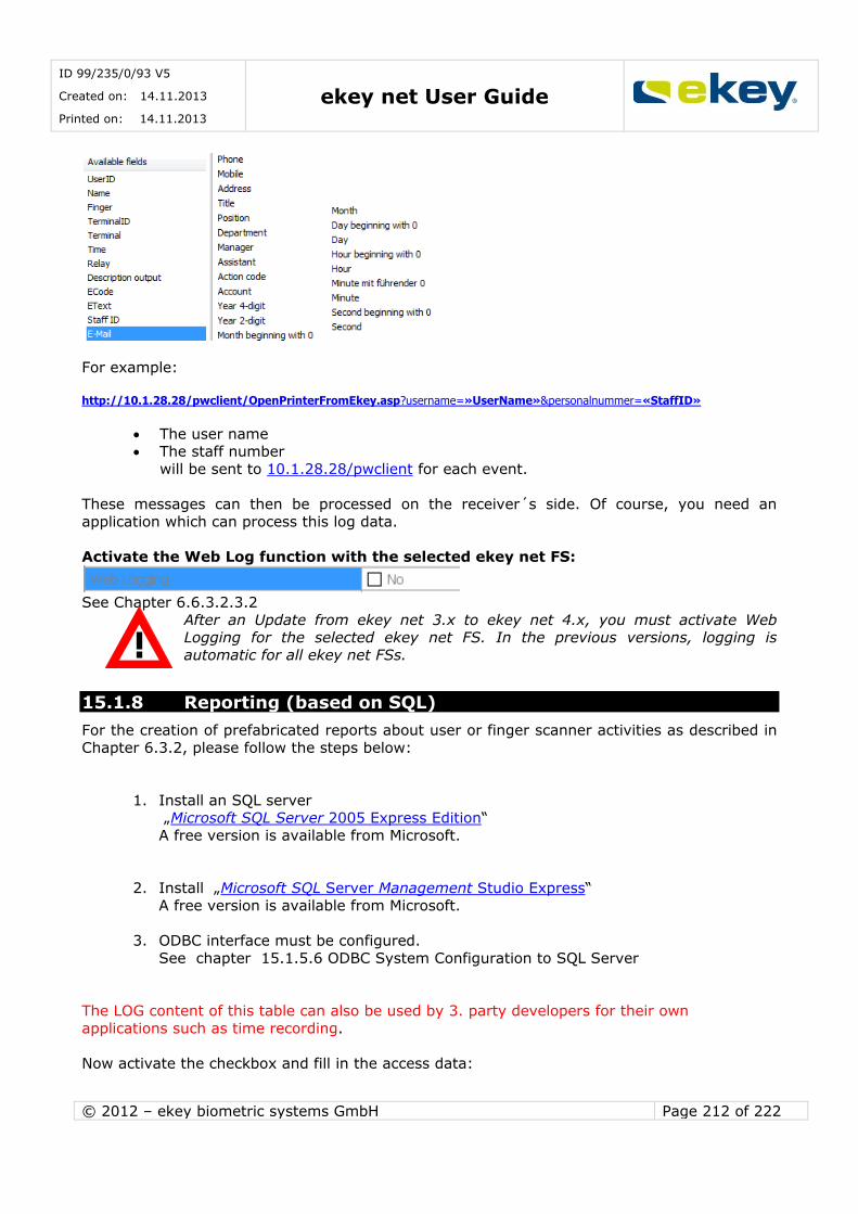
ID 99/235/0/93 V5
Created on: 14.11.2013
Printed on: 14.11.2013 ekey net User Guide
© 2012 – ekey biometric systems GmbH Page 212 of 222
For example:
http://10.1.28.28/pwclient/OpenPrinterFromEkey.asp?username=«UserName»&personalnummer=«StaffID»
The user name The staff number
will be sent to 10.1.28.28/pwclient for each event.
These messages can then be processed on the receiver´s side. Of course, you need an
application which can process this log data.
Activate the Web Log function with the selected ekey net FS:
See Chapter 6.6.3.2.3.2
After an Update from ekey net 3.x to ekey net 4.x, you must activate Web Logging for the selected ekey net FS. In the previous versions, logging is
automatic for all ekey net FSs.
15.1.8 Reporting (based on SQL)
For the creation of prefabricated reports about user or finger scanner activities as described in
Chapter 6.3.2, please follow the steps below:
1. Install an SQL server „Microsoft SQL Server 2005 Express Edition“
A free version is available from Microsoft.
2. Install „Microsoft SQL Server Management Studio Express“
A free version is available from Microsoft.
3. ODBC interface must be configured.
See chapter 15.1.5.6 ODBC System Configuration to SQL Server
The LOG content of this table can also be used by 3. party developers for their own
applications such as time recording.
Now activate the checkbox and fill in the access data:
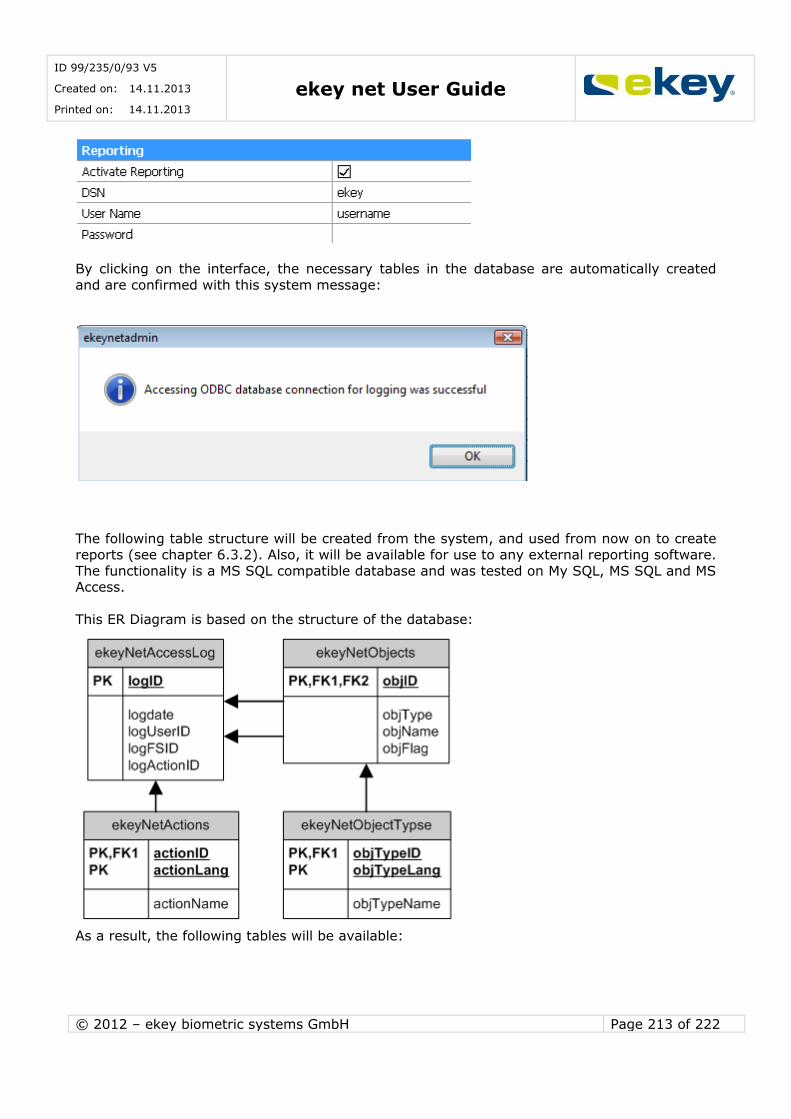
ID 99/235/0/93 V5
Created on: 14.11.2013
Printed on: 14.11.2013 ekey net User Guide
© 2012 – ekey biometric systems GmbH Page 213 of 222
By clicking on the interface, the necessary tables in the database are automatically created
and are confirmed with this system message:
The following table structure will be created from the system, and used from now on to create reports (see chapter 6.3.2). Also, it will be available for use to any external reporting software.
The functionality is a MS SQL compatible database and was tested on My SQL, MS SQL and MS Access.
This ER Diagram is based on the structure of the database:
As a result, the following tables will be available:
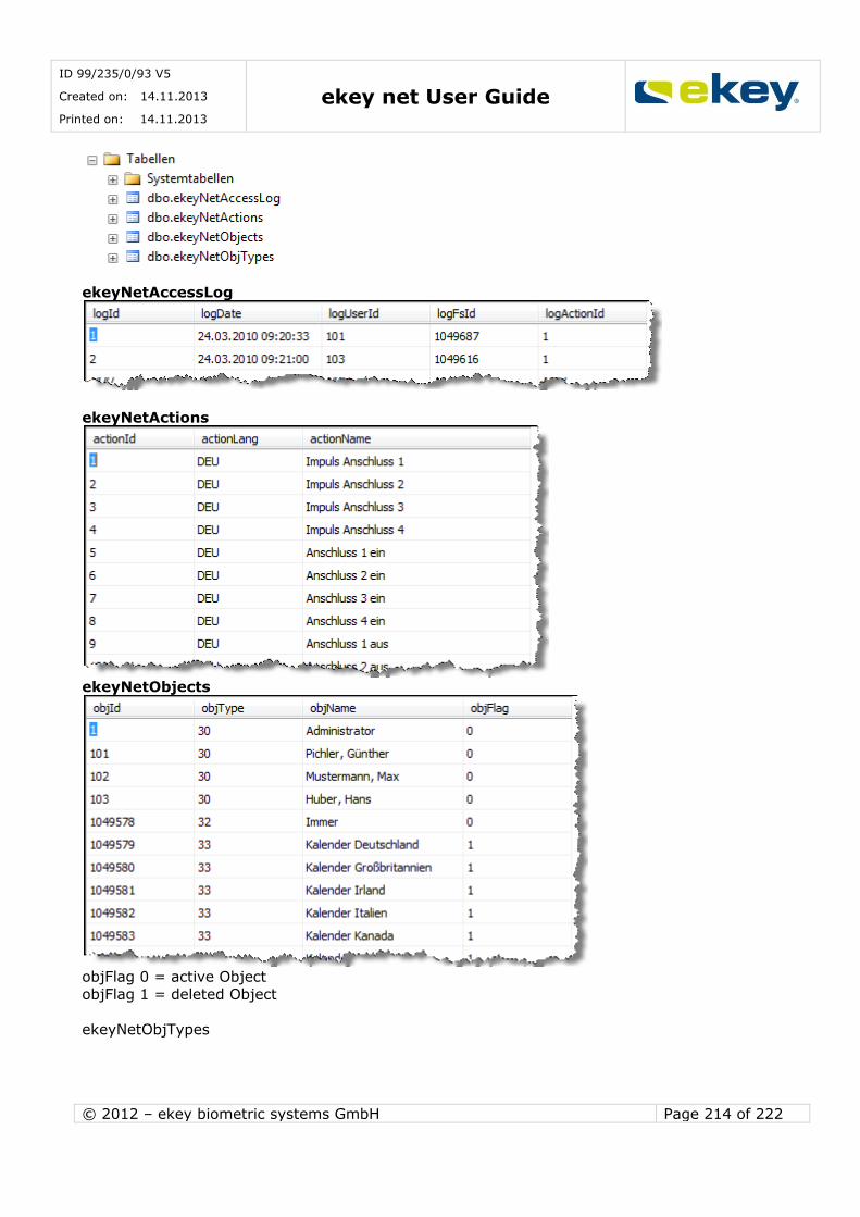
ID 99/235/0/93 V5
Created on: 14.11.2013
Printed on: 14.11.2013 ekey net User Guide
© 2012 – ekey biometric systems GmbH Page 214 of 222
ekeyNetAccessLog
ekeyNetActions
ekeyNetObjects
objFlag 0 = active Object
objFlag 1 = deleted Object
ekeyNetObjTypes

ID 99/235/0/93 V5
Created on: 14.11.2013
Printed on: 14.11.2013 ekey net User Guide
© 2012 – ekey biometric systems GmbH Page 215 of 222
16 Area Limits
16.1 General
Within ekey net, it is also possible to define events triggering actions for a group of devices
linked together (area). This way, you can for instance automatically open all doors in the area with one finger swipe.
Areas in ekey net are defined according to area limits. Such limits can be:
ekey CV LAN
ekey net Terminal Server ekey net Terminal Groups
If the ekey net CV LAN is defined as an area limit, all devices (i.e. finger scanner and control panels) assigned under it belong to this respective area. An area action (respectively an area
event) which is triggered within this device group, works on all devices in this area.
ATTENTION: The “Area Action” will also search for devices sitting in the above structure, until the next area limit was found. If you have NOT limited the area, the
entire ekey net system could theoretically be affected and all ekey net CP would switch.
To prevent this to happen, the configured area limits will NOT use the assigned
ekey net CV LAN automatically –defined on the level above –as such a border.
16.2 Defining the Area Limits
In Terminal Explorer the area limits and the Organisation are apparent.
ekey net Terminal Groups
ekey net Terminal Server
ekey net CV LAN
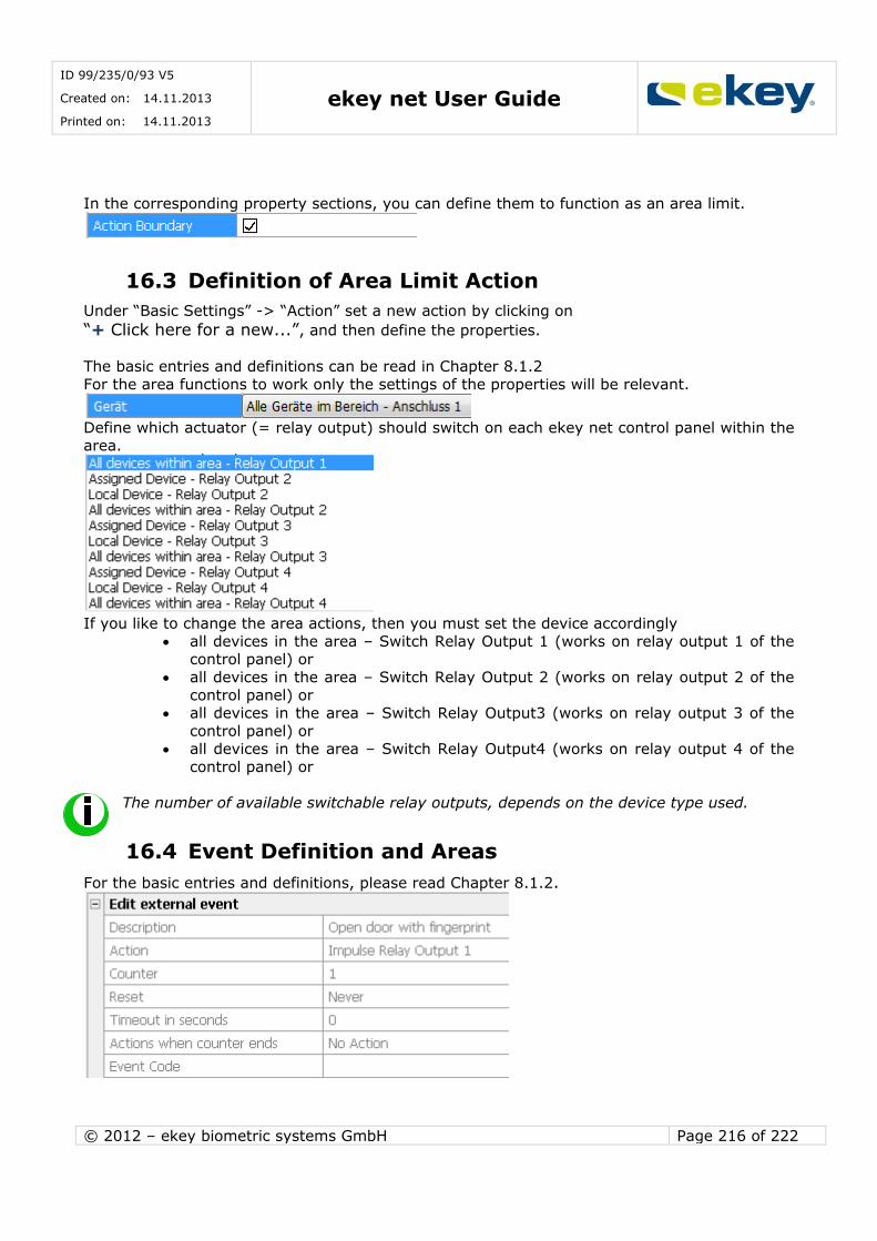
ID 99/235/0/93 V5
Created on: 14.11.2013
Printed on: 14.11.2013 ekey net User Guide
© 2012 – ekey biometric systems GmbH Page 216 of 222
In the corresponding property sections, you can define them to function as an area limit.
16.3 Definition of Area Limit Action
Under “Basic Settings” -> “Action” set a new action by clicking on
“+ Click here for a new...”, and then define the properties.
The basic entries and definitions can be read in Chapter 8.1.2
For the area functions to work only the settings of the properties will be relevant.
Define which actuator (= relay output) should switch on each ekey net control panel within the area.
If you like to change the area actions, then you must set the device accordingly
all devices in the area – Switch Relay Output 1 (works on relay output 1 of the control panel) or
all devices in the area – Switch Relay Output 2 (works on relay output 2 of the
control panel) or all devices in the area – Switch Relay Output3 (works on relay output 3 of the
control panel) or all devices in the area – Switch Relay Output4 (works on relay output 4 of the
control panel) or
The number of available switchable relay outputs, depends on the device type used.
16.4 Event Definition and Areas
For the basic entries and definitions, please read Chapter 8.1.2.

ID 99/235/0/93 V5
Created on: 14.11.2013
Printed on: 14.11.2013 ekey net User Guide
© 2012 – ekey biometric systems GmbH Page 217 of 222
Define a new event and allocate this to the area action. In this example we want to
open all doors in the production department.
When working with areas, you must define only 1 event triggering 1 action.
If you define an “Action when Counter ends”, please note that this second action will
only be triggered on the finger scanner on which the finger was presented. In other words, this second option will not affect the control panels grouped into an area.
For the same reason, you cannot run 2 actions in parallel when
working with area limits!!
16.5 Assignment to Finger and User
Lastly, assign the “area” event to the fingerprint of the relevant user.
Click
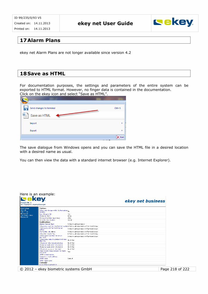
ID 99/235/0/93 V5
Created on: 14.11.2013
Printed on: 14.11.2013 ekey net User Guide
© 2012 – ekey biometric systems GmbH Page 218 of 222
17 Alarm Plans
ekey net Alarm Plans are not longer available since version 4.2
18 Save as HTML
For documentation purposes, the settings and parameters of the entire system can be
exported to HTML format. However, no finger data is contained in the documentation. Click on the ekey icon and select “Save as HTML”.
The save dialogue from Windows opens and you can save the HTML file in a desired location with a desired name as usual.
You can then view the data with a standard internet browser (e.g. Internet Explorer).
Here is an example:
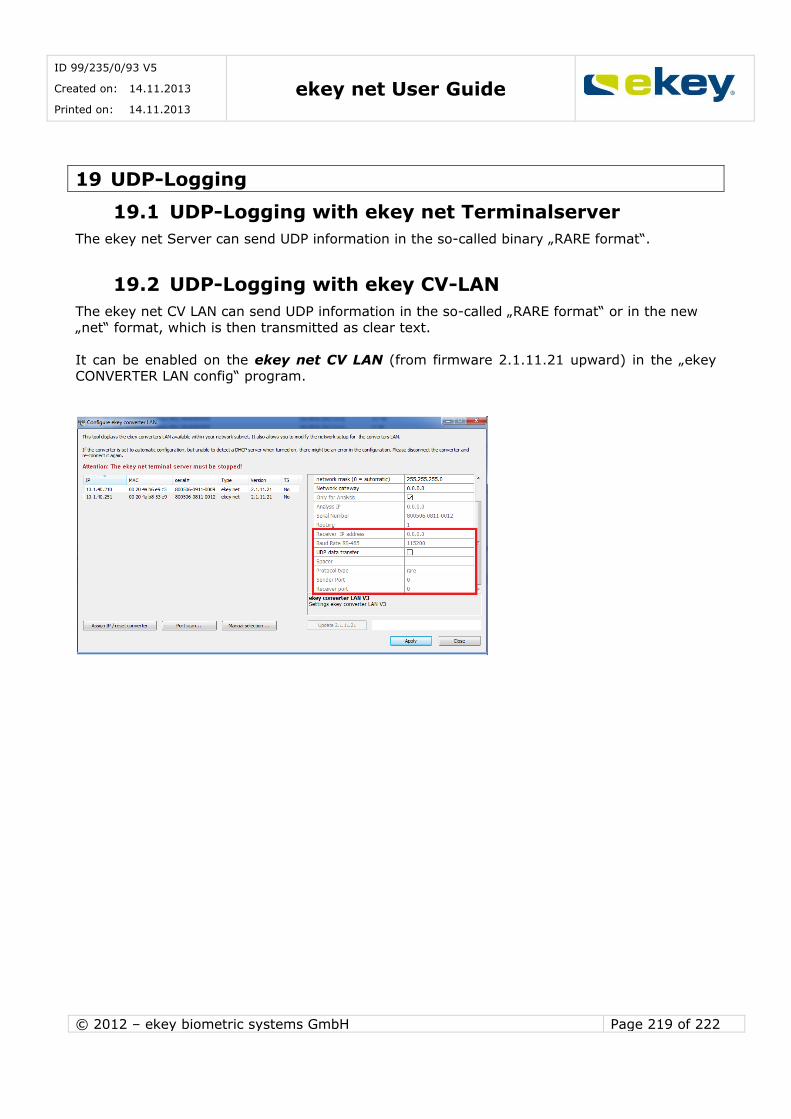
ID 99/235/0/93 V5
Created on: 14.11.2013
Printed on: 14.11.2013 ekey net User Guide
© 2012 – ekey biometric systems GmbH Page 219 of 222
19 UDP-Logging
19.1 UDP-Logging with ekey net Terminalserver
The ekey net Server can send UDP information in the so-called binary „RARE format“.
19.2 UDP-Logging with ekey CV-LAN
The ekey net CV LAN can send UDP information in the so-called „RARE format“ or in the new
„net“ format, which is then transmitted as clear text.
It can be enabled on the ekey net CV LAN (from firmware 2.1.11.21 upward) in the „ekey CONVERTER LAN config“ program.
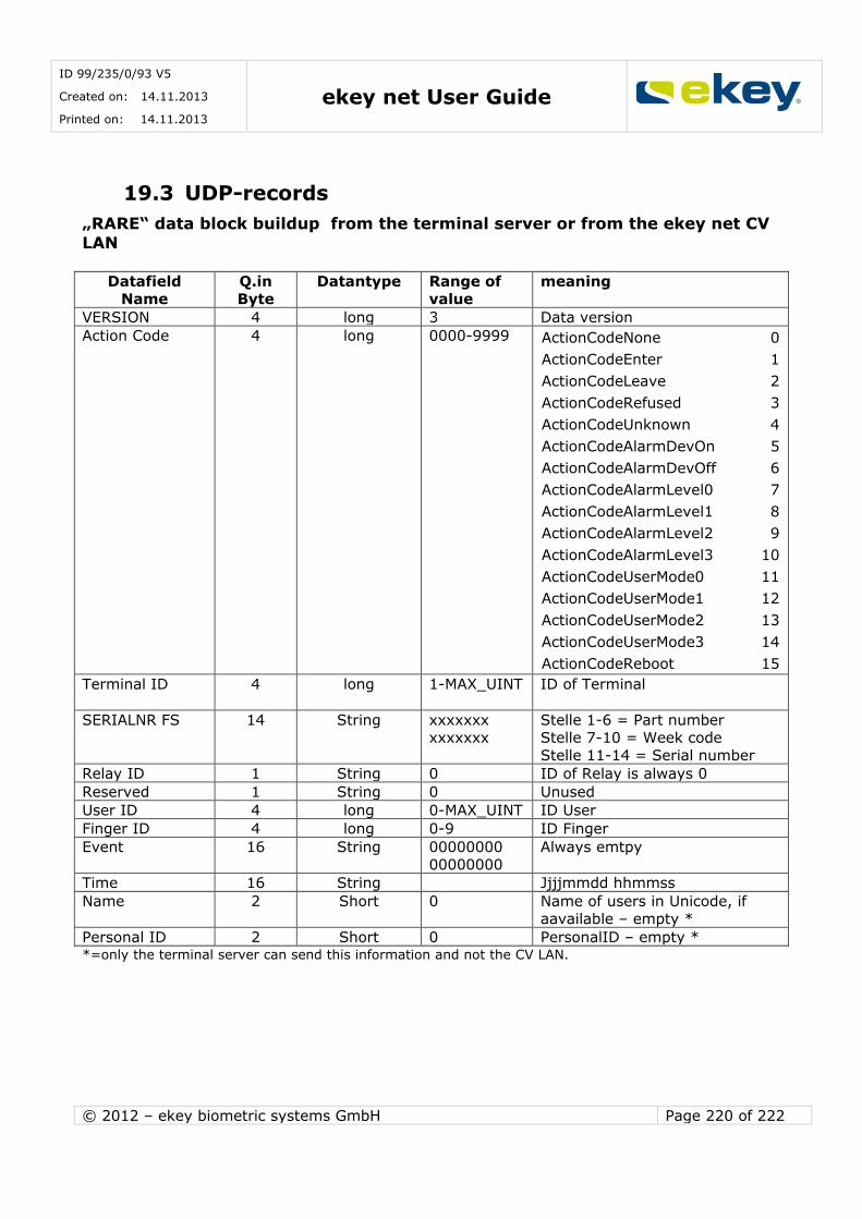
ID 99/235/0/93 V5
Created on: 14.11.2013
Printed on: 14.11.2013 ekey net User Guide
© 2012 – ekey biometric systems GmbH Page 220 of 222
19.3 UDP-records
„RARE“ data block buildup from the terminal server or from the ekey net CV LAN
Datafield
Name
Q.in
Byte
Datantype Range of
value
meaning
VERSION 4 long 3 Data version
Action Code 4 long 0000-9999 ActionCodeNone 0
ActionCodeEnter 1
ActionCodeLeave 2
ActionCodeRefused 3
ActionCodeUnknown 4
ActionCodeAlarmDevOn 5
ActionCodeAlarmDevOff 6
ActionCodeAlarmLevel0 7
ActionCodeAlarmLevel1 8
ActionCodeAlarmLevel2 9
ActionCodeAlarmLevel3 10
ActionCodeUserMode0 11
ActionCodeUserMode1 12
ActionCodeUserMode2 13
ActionCodeUserMode3 14
ActionCodeReboot 15
Terminal ID 4 long 1-MAX_UINT
ID of Terminal
SERIALNR FS 14 String xxxxxxx
xxxxxxx
Stelle 1-6 = Part number
Stelle 7-10 = Week code
Stelle 11-14 = Serial number
Relay ID 1 String 0 ID of Relay is always 0
Reserved 1 String 0 Unused
User ID 4 long 0-MAX_UINT ID User
Finger ID 4 long 0-9 ID Finger
Event 16 String 00000000
00000000
Always emtpy
Time 16 String Jjjjmmdd hhmmss
Name 2 Short 0 Name of users in Unicode, if
aavailable – empty *
Personal ID 2 Short 0 PersonalID – empty * *=only the terminal server can send this information and not the CV LAN.

ID 99/235/0/93 V5
Created on: 14.11.2013
Printed on: 14.11.2013 ekey net User Guide
© 2012 – ekey biometric systems GmbH Page 221 of 222
„net“ data block buildup from the ekey net CV LAN
Datafield Name digits Datentype Range
of value meaning
PACKAGE TYPE 1 String 1 Packag etype „User data“
USER ID 6 String (dezimal) 0-
999999
UserID from ekey net
000000: not defined
FINGER ID 1 String (dezimal) 0-9
1 = left small finger
2 = left ring finger . .
0 = right small finger ‚-‚= no finger
SERIALNR FS 14 String xxxxxxx
xxxxxxx
Digit 1-6 = Part number
Digit 7-10 = Week code Digit 11-14 = Serial number
EVENT 6 String 0-
999999
EventID from ekey net
In order to test UDP packet sending, you can use a UDP Sniffer tool like www.wireshark.org

ID 99/235/0/93 V5
Created on: 14.11.2013
Printed on: 14.11.2013 ekey net User Guide
© 2012 – ekey biometric systems GmbH Page 222 of 222
20 ekey net SDK
ekey net has a software interface that allows control over external applications (time recording
etc.). This interface is not described in detail within the scope of this user guide. For further information on this, please contact ekey.
21 Maintenance
21.1 Software
Despite the fact that ekey net is a high quality software product, individual isolated
malfunctions may occur. Please report errors to the ekey technical support department. ekey publishes new versions in regular time intervals (about twice a year) with
bugs new features
Performance improvements.
You can be informed of new Versions from ekey net on our webpage www.ekey.net.
21.2 Hardware
The basic hardware components:
ekey net FS ekey net CP
ekey CV LAN ekey CV WIEG
no special maintenance necessary.
Damage We recommend undergoing a visual inspection of all devices at least once a year and recording
of
defective housing and housing components possible cable damage
etc. and damage.
Impurities Impurities on the ekey net FS, especially in the sensor area are removed with a damp (not
wet!!!), not “scratchy or abrasive” cloth. Also use only warm water without detergents,
solvents, etc.