Embed Size (px)
Citation preview

Operation Instructions
MIB20_30_40 OPERATION MANUAL 2003_05 - 1 -
Operating Instructions
MAGSTOP Traffic Barrier MIB 20/30/40
MLC Controller Unit
Version 2003_05
Operation Instructions
MIB20_30_40 OPERATION MANUAL 2003_05
2
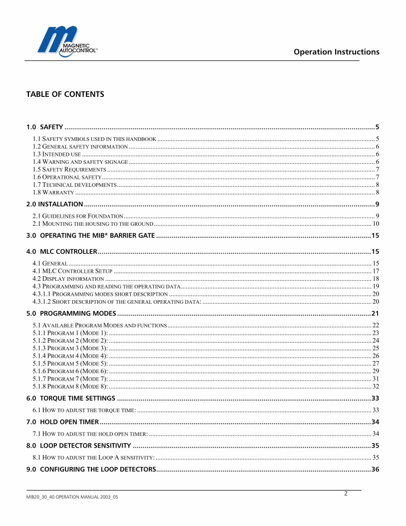
TABLE OF CONTENTS
1.0 SAFETY ...............................................................................................................................................................5 1.1 SAFETY SYMBOLS USED IN THIS HANDBOOK .................................................................................................................................. 5 1.2 GENERAL SAFETY INFORMATION ................................................................................................................................................... 6 1.3 INTENDED USE ............................................................................................................................................................................... 6 1.4 WARNING AND SAFETY SIGNAGE ................................................................................................................................................... 6 1.5 SAFETY REQUIREMENTS ................................................................................................................................................................ 7 1.6 OPERATIONAL SAFETY................................................................................................................................................................... 7 1.7 TECHNICAL DEVELOPMENTS.......................................................................................................................................................... 8 1.8 WARRANTY ................................................................................................................................................................................... 8
2.0 INSTALLATION.....................................................................................................................................................9 2.1 GUIDELINES FOR FOUNDATION...................................................................................................................................................... 9 2.1 MOUNTING THE HOUSING TO THE GROUND.................................................................................................................................. 10
3.0 OPERATING THE MIB* BARRIER GATE ..............................................................................................................15
4.0 MLC CONTROLLER............................................................................................................................................15 4.1 GENERAL..................................................................................................................................................................................... 15 4.1 MLC CONTROLLER SETUP .......................................................................................................................................................... 17 4.2 DISPLAY INFORMATION ............................................................................................................................................................... 18 4.3 PROGRAMMING AND READING THE OPERATING DATA.................................................................................................................. 19 4.3.1.1 PROGRAMMING MODES SHORT DESCRIPTION ......................................................................................................................... 20 4.3.1.2 SHORT DESCRIPTION OF THE GENERAL OPERATING DATA: ..................................................................................................... 20
5.0 PROGRAMMING MODES ..................................................................................................................................21 5.1 AVAILABLE PROGRAM MODES AND FUNCTIONS.......................................................................................................................... 22 5.1.1 PROGRAM 1 (MODE 1): ............................................................................................................................................................. 23 5.1.2 PROGRAM 2 (MODE 2): ............................................................................................................................................................. 24 5.1.3 PROGRAM 3 (MODE 3): ............................................................................................................................................................. 25 5.1.4 PROGRAM 4 (MODE 4): ............................................................................................................................................................. 26 5.1.5 PROGRAM 5 (MODE 5): ............................................................................................................................................................. 27 5.1.6 PROGRAM 6 (MODE 6): ............................................................................................................................................................. 29 5.1.7 PROGRAM 7 (MODE 7): ............................................................................................................................................................. 31 5.1.8 PROGRAM 8 (MODE 8): ............................................................................................................................................................. 32
6.0 TORQUE TIME SETTINGS ..................................................................................................................................33 6.1 HOW TO ADJUST THE TORQUE TIME: ............................................................................................................................................ 33
7.0 HOLD OPEN TIMER...........................................................................................................................................34 7.1 HOW TO ADJUST THE HOLD OPEN TIMER: ..................................................................................................................................... 34
8.0 LOOP DETECTOR SENSITIVITY ..........................................................................................................................35 8.1 HOW TO ADJUST THE LOOP A SENSITIVITY: ................................................................................................................................. 35
9.0 CONFIGURING THE LOOP DETECTORS..............................................................................................................36
Operation Instructions
MIB20_30_40 OPERATION MANUAL 2003_05 - 3 -
9.1 SAFETY/CLOSING LOOP A........................................................................................................................................................... 36 9.2 LOOP A MODE FUNCTION............................................................................................................................................................ 37
9.2.1 Detector Mode A............................................................................................................................................................................... 37 9.2.2 Directional Logic Loop A ................................................................................................................................................................. 37 9.3.1 Detector mode B ............................................................................................................................................................................... 40 9.3.2 Directional Logic Loop B ................................................................................................................................................................. 40
10.0 LOOP FREQUENCY.......................................................................................................................................... 42 10.1 HOW TO VIEW THE LOOP FREQUENCY:....................................................................................................................................... 42 10.2 HOW TO CHANGE THE LOOP FREQUENCY:.................................................................................................................................. 43
11.0 RELAY K1 OUTPUT.......................................................................................................................................... 44
12.0 ERROR CODE.................................................................................................................................................. 46
13.0 LANGUAGE SETTING ...................................................................................................................................... 46
14.0 DEFAULT SETTINGS ........................................................................................................................................ 47
15.0 EXTENDED MENU SETTINGS: ......................................................................................................................... 48 15.1 ADJUSTING THE SAFETY ANGLE:................................................................................................................................................ 49 15.2 OPERATING HOUR DISPLAY: ...................................................................................................................................................... 50 15.3 GATE CYCLE COUNTER: ............................................................................................................................................................ 50 15.4 READING THE BRAKE POINTS:................................................................................................................................................... 51 15.5 RESETTING THE BARRIER AFTER POWER FAILURE:..................................................................................................................... 51 15.6 TEST MODE ............................................................................................................................................................................... 52
16.0 INSTALLING THE INDUCTION LOOPS.............................................................................................................. 54 16.1 GENERAL INDUCTION LOOP FUNCTIONALITY............................................................................................................................. 54 16.2 LOOP INDUCTANCE ................................................................................................................................................................... 54 16.2.1 INDUCTANCE .......................................................................................................................................................................... 54 16.2.2 VEHICLE DETECTION .............................................................................................................................................................. 55 16.2.3 WIRE TURNS REQUIRED FOR LOOPS........................................................................................................................................ 55 16.2.4 LOOP INDUCTANCE CALCULATIONS ....................................................................................................................................... 56 16.3 LOOP DETECTOR SENSITIVITY................................................................................................................................................... 57 16.4 INSTALLING A INDUCTION LOOP ............................................................................................................................................... 57 16.4.1 USAGE OF PRE-MANUFACTURED LOOPS................................................................................................................................. 57 16.4.2 SELF-MADE LOOPS ................................................................................................................................................................ 58 16.4.3 LOOP LEAD WIRES ................................................................................................................................................................. 58 16.4.4 HOW DEEP SHOULD THE LOOP WIRES BE INSTALLED?............................................................................................................. 59 16.4.5 LOOP DISTANCE FROM OBJECTS:............................................................................................................................................. 60
17.0 COMMISSIONING........................................................................................................................................... 61 17.1 COMMISSIONING PROCEDURE.................................................................................................................................................... 61 17.3 STANDARD CONFIGURATION:.................................................................................................................................................... 62 17.3.1 PARKING OR ACCESS CONTROL CONFIGURATION: .............................................................................................................. 62 17.3.2 TOLL ROAD APPLICATION: ................................................................................................................................................. 62
18.0 INSTALLATION EXAMPLE: .............................................................................................................................. 63 18.1 FREE EXIT OR ENTRY CONFIGURATION: ..................................................................................................................................... 63 18.1.1 FREE ENTRY OR EXIT LANE LAYOUT ...................................................................................................................................... 64 18.1.2 FREE ENTRY OR EXIT WIRING DIAGRAM: ................................................................................................................................ 65 18.2 ENTRY OR EXIT WITH ACCESS CONTROL:................................................................................................................................... 66
Operation Instructions
MIB20_30_40 OPERATION MANUAL 2003_05
4
18.2.1 ACCESS CONTROL LANE LAYOUT........................................................................................................................................... 67 18.2.2 ACCESS CONTROL LANE WIRING DIAGRAM ............................................................................................................................ 68 18.3 ACCESS CONTROL ONE DIRECTION FREE IN/OUT OTHER DIRECTION........................................................................................... 69 18.3.1 ACCESS CONTROL IN FREE OUT LANE LAYOUT ..................................................................................................................... 70 18.3.2 ACCESS CONTROL IN FREE OUT LANE WIRING DIAGRAM....................................................................................................... 71 18.4 MASTER SLAVE CONFIGURATION .............................................................................................................................................. 72 18.4.1 MASTER/SLAVE LANE LAYOUT .............................................................................................................................................. 74 18.4.2 MASTER SLAVE WIRING DIAGRAM.......................................................................................................................................... 75 18.5 TOLL ROAD APPLICATION:......................................................................................................................................................... 76 18.5.1 TOLL ROAD LANE LAYOUT ..................................................................................................................................................... 77 18.5.2 TOLL ROAD WIRING DIAGRAM................................................................................................................................................ 78
19.0 MIB* BARRIER WITH BOOM LOCK MECHANISM ............................................................................................79
20.0 MIB* BARRIER WITH BOOM LIGHTS ...............................................................................................................80
21.0 MECHANICAL OPERATION..............................................................................................................................81 21.1 SPRING BALANCE....................................................................................................................................................................... 81 21.2 BARRIER ARM SUPPORT ............................................................................................................................................................. 83 21.2.1 PENDULUM SUPPORT............................................................................................................................................................... 83 21.2.2 SUPPORT POST ........................................................................................................................................................................ 83
22.0 TROUBLESHOOTING .......................................................................................................................................85 22.1 ADJUSTING THE BOOM POSITION SENSOR................................................................................................................................... 85 22.2 BOOM SENSOR OUT OF ADJUSTMENT ......................................................................................................................................... 88 22.3 LOOP DETECTOR ERROR ............................................................................................................................................................ 91 22.4 GATE DOES NOT CLOSE .............................................................................................................................................................. 92 22.5 GATE DOES NOT OPEN................................................................................................................................................................ 93 22.6 HOW TO CHANGE FROM RIGHT-HANDED GATE TO LEFT- HANDED? ............................................................................................ 94
23.0 TECHNICAL DATA ...........................................................................................................................................96 23.1 MAGSTOP BARRIERS .............................................................................................................................................................. 96 23.2 CONTROLLER............................................................................................................................................................................. 96
24. MAINTENANCE.................................................................................................................................................98 24.1 CHANGING THE RUBBER END STOP ........................................................................................................................................... 98 24.2 CHECKING THE EXTERIOR OF CABINET ..................................................................................................................................... 98 24.3 CHECK THE BARRIER ARM AND THE ATTACHMENT KIT .............................................................................................................. 98 24.4 CHECKING THE LOOP DETECTORS AND LOOP WIRES ................................................................................................................ 98 24.5 CHECK SAFETY SIGNAGE ........................................................................................................................................................... 98 24.5 MAINTENANCE SERVICE RECORD.............................................................................................................................................. 99 24.5 MAINTENANCE SERVICE RECORD............................................................................................................................................ 100
25. SPARE PARTS..................................................................................................................................................101
Operation Instructions
MIB20_30_40 OPERATION MANUAL 2003_05 - 5 -
1.0 Safety
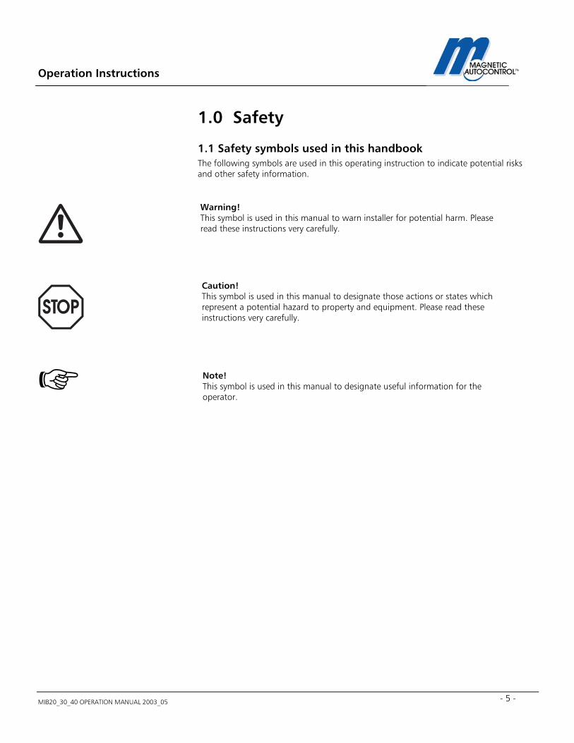
1.1 Safety symbols used in this handbook The following symbols are used in this operating instruction to indicate potential risks and other safety information.
Caution! This symbol is used in this manual to designate those actions or states which represent a potential hazard to property and equipment. Please read these instructions very carefully.
Note! This symbol is used in this manual to designate useful information for the operator.
Warning! This symbol is used in this manual to warn installer for potential harm. Please read these instructions very carefully.
Operation Instructions
MIB20_30_40 OPERATION MANUAL 2003_05
6
1.2 General safety information This MAGSTOP barrier system has been designed, built and tested using state-of-the-art technology and left our factory only after passing stringent safety and reliability criteria. Nevertheless the barrier system can represent a risk to persons and property if it is not installed and operated correctly. These operating instructions must therefore be read in their entirety and all safety information contained therein must be complied with. The manufacturer shall refuse to accept liability and shall withdraw warranty if this barrier system is used incorrectly or is used for a purpose for which it was not intended.
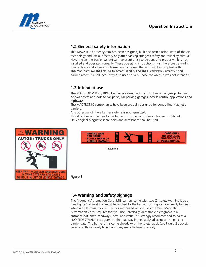
1.3 Intended use The MAGSTOP MIB 20/30/40 barriers are designed to control vehicular (see pictogram below) access and exits to car parks, car parking garages, access control applications and highways. The MAGTRONIC control units have been specially designed for controlling Magnetic barriers. Any other use of these barrier systems is not permitted. Modifications or changes to the barrier or to the control modules are prohibited. Only original Magnetic spare parts and accessories shall be used.
Figure 2
Figure 1
1.4 Warning and safety signage The Magnetic Automation Corp. MIB barriers come with two (2) safety warning labels (see Figure 1 above) that must be applied to the barrier housing so it can easily be seen when a pedestrian, bicycle users, or motorized vehicle uses the lane. Magnetic Automation Corp. requires that you use universally identifiable pictograms in all entrance/exit lanes, roadways, post, and walls. It is strongly recommended to paint a “NO PEDESTRIAN” pictogram on the roadway immediately adjacent to the parking barrier gate. The barrier arms come already with the safety labels (see Figure 2 above). Removing those safety labels voids any manufacturer’s liability.
Operation Instructions
MIB20_30_40 OPERATION MANUAL 2003_05 - 7 -
1.5 Safety Requirements - Use vibrant colors on parking equipment - Always provide proper signage, both on the road way and on other equipment - Maintain manufacturers warning stickers on gate housing and gate arms. - Always require that sidewalks are parallel to entrance and exit lanes, or require having pedestrian entrances on opposite side of vehicle entrance and exit.
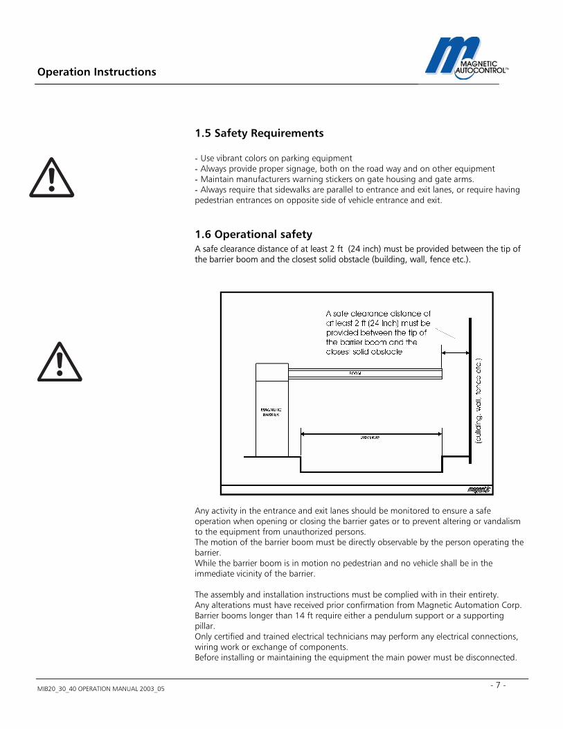
1.6 Operational safety A safe clearance distance of at least 2 ft (24 inch) must be provided between the tip of the barrier boom and the closest solid obstacle (building, wall, fence etc.).
Any activity in the entrance and exit lanes should be monitored to ensure a safe operation when opening or closing the barrier gates or to prevent altering or vandalism to the equipment from unauthorized persons. The motion of the barrier boom must be directly observable by the person operating the barrier. While the barrier boom is in motion no pedestrian and no vehicle shall be in the immediate vicinity of the barrier.
The assembly and installation instructions must be complied with in their entirety. Any alterations must have received prior confirmation from Magnetic Automation Corp. Barrier booms longer than 14 ft require either a pendulum support or a supporting pillar. Only certified and trained electrical technicians may perform any electrical connections, wiring work or exchange of components. Before installing or maintaining the equipment the main power must be disconnected.
Operation Instructions
MIB20_30_40 OPERATION MANUAL 2003_05
8
1.7 Technical developments The manufacturer reserves the right to modify, without prior notice, the technical specifications in order to accommodate the latest technical developments. Magnetic Automation Corp. will provide information on the status of existing operating instructions and on any alterations and extensions that may be relevant.
1.8 Warranty Magnetic provides a limited warranty on its barriers that covers all mechanical and electrical components, but excludes parts subject to wear and tear, for a period of two years from the date of first use or for a maximum of three years from the date on which the system was delivered provided that the operating instructions have been complied with, no unauthorized servicing of machine components has taken place, and that no mechanical damage to the machines is evident. Please refer to our Warranty Statement. NOTE: NONE COMPLYANCE WITH THE ABOVE SAFETY REQUIREMENTS (all of Chapter 1) SHALL VOID ANY MANUFACTURERS LIABILITY!
COPYRIGHT 2001 Magnetic Automation Corp. All rights reserved. No part of this publication may be reproduced, transmitted, transcribed, stored in a retrieval system, or translated into any language in any form by any means without the written permission of Magnetic Automation Corp. First Printing: 2001
Operation Instructions
MIB20_30_40 OPERATION MANUAL 2003_05 - 9 -
2.0 Installation
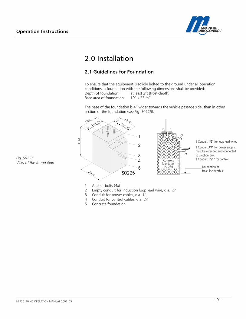
2.1 Guidelines for Foundation To ensure that the equipment is solidly bolted to the ground under all operation conditions, a foundation with the following dimensions shall be provided: Depth of foundation: at least 3ft (frost-depth) Base area of foundation: 19” x 23 ½” The base of the foundation is 4” wider towards the vehicle passage side, than in other section of the foundation (see Fig. S0225).
Fig. S0225 View of the foundation
1 Anchor bolts (4x) 2 Empty conduit for induction loop lead wire, dia. ½” 3 Conduit for power cables, dia. 1” 4 Conduit for control cables, dia. ½” 5 Concrete foundation
1 2 3 4
5
311/
2
S0225Foundation atfrost-line depth 3’
Concretefoundation
PC 250
1 Conduit 1/2” for loop lead wires
1 Conduit 3/4” for power supplymust be extended and connectedto junction box1 Conduit 1/2”” for control
Operation Instructions
MIB20_30_40 OPERATION MANUAL 2003_05
10
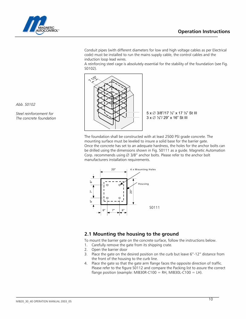
Conduit pipes (with different diameters for low and high voltage cables as per Electrical code) must be installed to run the mains supply cable, the control cables and the induction loop lead wires. A reinforcing steel cage is absolutely essential for the stability of the foundation (see Fig. S0102).
Abb. S0102 Steel reinforcement for The concrete foundation
The foundation shall be constructed with at least 2500 PSI grade concrete. The mounting surface must be leveled to insure a solid base for the barrier gate. Once the concrete has set to an adequate hardness, the holes for the anchor bolts can be drilled using the dimensions shown in Fig. S0111 as a guide. Magnetic Automation Corp. recommends using ∅ 3/8” anchor bolts. Please refer to the anchor bolt manufacturers installation requirements.
2.1 Mounting the housing to the ground To mount the barrier gate on the concrete surface, follow the instructions below. 1. Carefully remove the gate from its shipping crate. 2. Open the barrier door 3. Place the gate on the desired position on the curb but leave 6”-12” distance from
the front of the housing to the curb line. 4. Place the gate so that the gate arm flange faces the opposite direction of traffic.
Please refer to the figure S0112 and compare the Packing list to assure the correct flange position (example: MIB30R-C100 = RH, MIB30L-C100 = LH).
5 x ∅ 3/8”/17 ½” x 17 ½” St III 3 x ∅ ½”/ 29” x 16” St III
6"6"
7"
7"6" 6"
20"
20"
4 x M ounting Holes
H ousing
S0111
Operation Instructions
MIB20_30_40 OPERATION MANUAL 2003_05 - 11 -
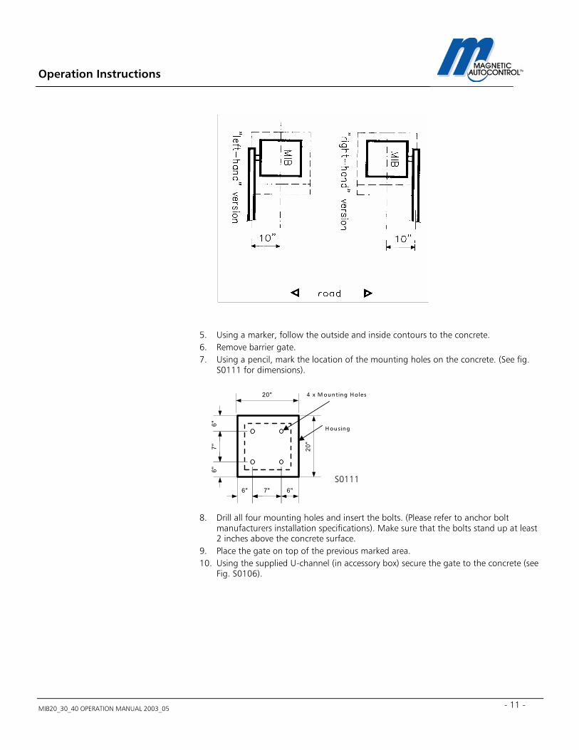
5. Using a marker, follow the outside and inside contours to the concrete. 6. Remove barrier gate. 7. Using a pencil, mark the location of the mounting holes on the concrete. (See fig.
S0111 for dimensions). 8. Drill all four mounting holes and insert the bolts. (Please refer to anchor bolt
manufacturers installation specifications). Make sure that the bolts stand up at least 2 inches above the concrete surface.
9. Place the gate on top of the previous marked area. 10. Using the supplied U-channel (in accessory box) secure the gate to the concrete (see
Fig. S0106).
6"6"
7"
7"6" 6"
20"
20"
4 x M ounting Holes
H ousing
S0111
Operation Instructions
MIB20_30_40 OPERATION MANUAL 2003_05
12
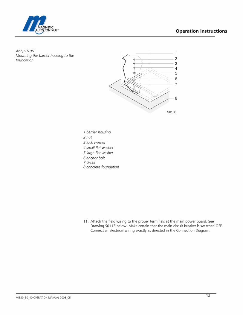
1 barrier housing 2 nut 3 lock washer 4 small flat washer 5 large flat washer 6 anchor bolt 7 U-rail 8 concrete foundation 11. Attach the field wiring to the proper terminals at the main power board. See
Drawing S0113 below. Make certain that the main circuit breaker is switched OFF. Connect all electrical wiring exactly as directed in the Connection Diagram.
1234567
8
S0106
Abb,S0106 Mounting the barrier housing to the foundation
Operation Instructions
MIB20_30_40 OPERATION MANUAL 2003_05 - 13 -
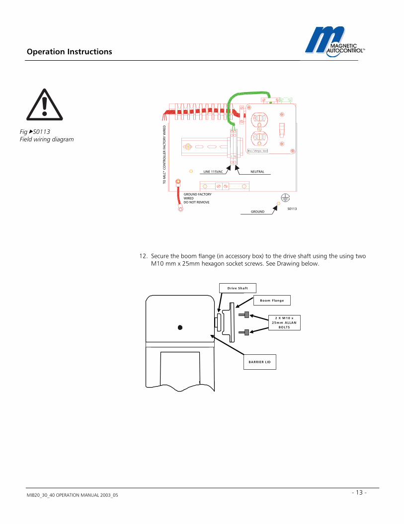
12. Secure the boom flange (in accessory box) to the drive shaft using the using two
M10 mm x 25mm hexagon socket screws. See Drawing below.
LINE 115VAC NEUTRAL
GROUNDS0113
TO M
LC*
CO
NTR
OLL
ER F
AC
TORY
WIR
ED
GROUND FACTORY WIREDDO NOT REMOVE
Fig S0113 Field wiring diagram
2 X M 10 x25m m A LLA N
BO LTS
Drive Shaft
Boom Flange
BA RRIER LID
Operation Instructions
MIB20_30_40 OPERATION MANUAL 2003_05
14
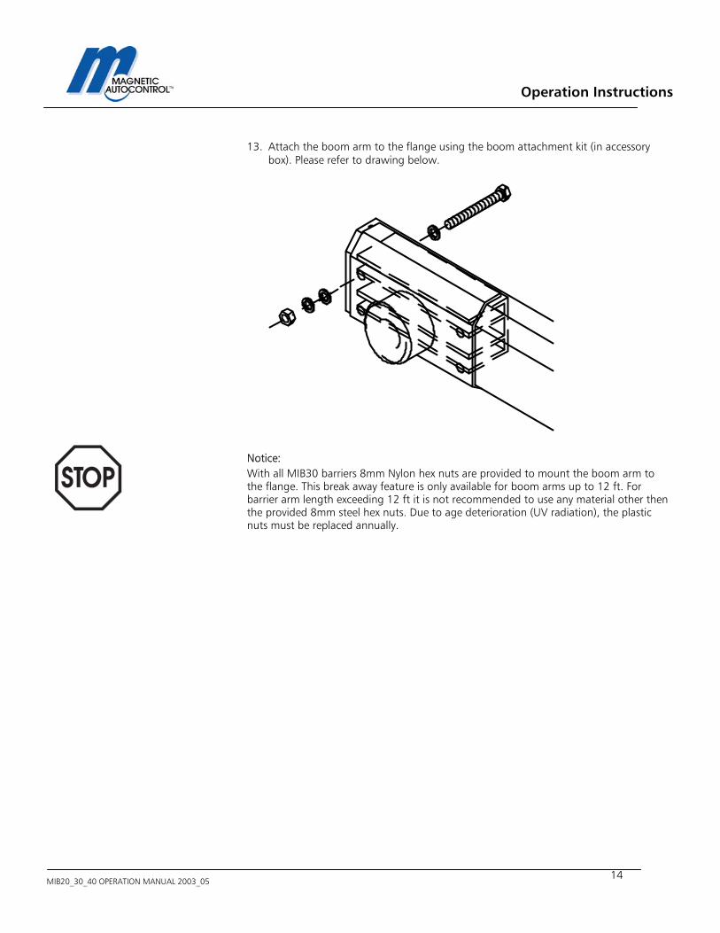
13. Attach the boom arm to the flange using the boom attachment kit (in accessory box). Please refer to drawing below.
Notice: With all MIB30 barriers 8mm Nylon hex nuts are provided to mount the boom arm to the flange. This break away feature is only available for boom arms up to 12 ft. For barrier arm length exceeding 12 ft it is not recommended to use any material other then the provided 8mm steel hex nuts. Due to age deterioration (UV radiation), the plastic nuts must be replaced annually.
Operation Instructions
MIB20_30_40 OPERATION MANUAL 2003_05 - 15 -
3.0 Operating the MIB* Barrier Gate In automatic operation, the MIB* Barrier gate can be operated using following devices: - Ticket Spitters - Vehicle Detectors - Card Readers - Coin and Token acceptors - Radio Controllers - Switches, Push buttons, and other devices.
4.0 MLC Controller
4.1 General The MLC control unit (Magnetic Lane Controller) has been specially designed for use with MIB 20/30/40 barrier gates. All standard configurations can be achieved with this new generation controller. Via a potentiometer (boom position sensor), located at the motor drive shaft, the position of the barrier arm is continuously detected and the MLC controller evaluates the information. This replaces the limit switch that is used in conventional barrier control systems. The combination of the potentiometer and the MLC unit guarantees the best possible control of the barrier boom movement. The controller also has a 16-digit LCD display that shows the current settings and in/out -put stages at any time. Software modifications are normally included at the factory but they can also be loaded very easily into the controller unit at some later date by connecting a software memory card via the interface connector. The barrier is factory wired and supplied ready for immediate connection.
Warning! The following description is based on the standard parameter S 24008. Other parameters sets are not described in this manual.
Operation Instructions
MIB20_30_40 OPERATION MANUAL 2003_05
16
00
Operation Instructions
MIB20_30_40 OPERATION MANUAL 2003_05 - 17 -
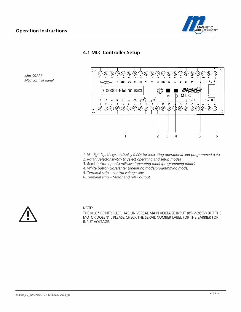
4.1 MLC Controller Setup
1 16- digit liquid crystal display (LCD) for indicating operational and programmed data 2. Rotary selector switch to select operating and setup modes 3. Black button open/scroll/save (operating mode/programming mode) 4. White button close/enter (operating mode/programming mode) 5. Terminal strip – control voltage side 6. Terminal strip – Motor and relay output NOTE: THE MLC* CONTROLLER HAS UNIVERSAL MAIN VOLTAGE INPUT (85-V-265V) BUT THE MOTOR DOESN’T. PLEASE CHECK THE SERAIL NUMBER LABEL FOR THE BARRIER FOR INPUT VOLTAGE.
1 2 3 4 5 6
Abb.S0227 MLC control panel
00
Operation Instructions
MIB20_30_40 OPERATION MANUAL 2003_05
18
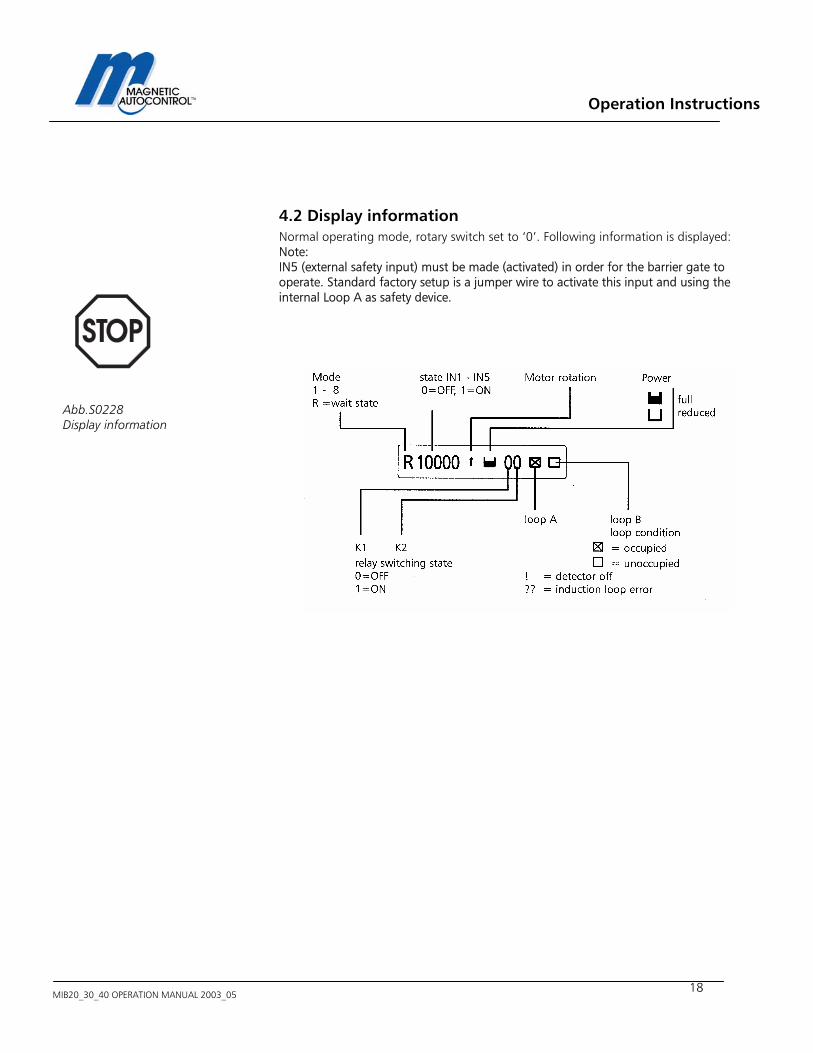
4.2 Display information Normal operating mode, rotary switch set to ‘0’. Following information is displayed: Note: IN5 (external safety input) must be made (activated) in order for the barrier gate to operate. Standard factory setup is a jumper wire to activate this input and using the internal Loop A as safety device.
Abb.S0228 Display information
Operation Instructions
MIB20_30_40 OPERATION MANUAL 2003_05 - 19 -
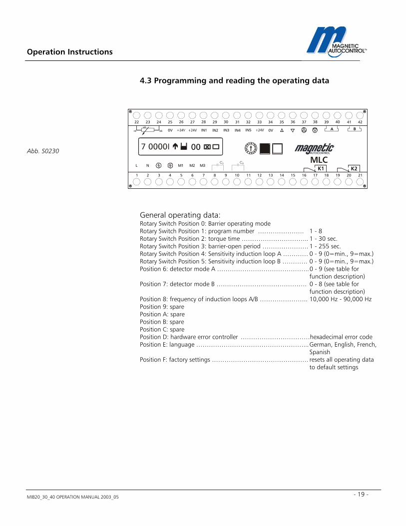
4.3 Programming and reading the operating data
General operating data: Rotary Switch Position 0: Barrier operating mode Rotary Switch Position 1: program number …………………. 1 - 8 Rotary Switch Position 2: torque time ………………………….. 1 - 30 sec. Rotary Switch Position 3: barrier-open period …………………. 1 - 255 sec. Rotary Switch Position 4: Sensitivity induction loop A ………… 0 - 9 (0=min., 9=max.) Rotary Switch Position 5: Sensitivity induction loop B ………… 0 - 9 (0=min., 9=max.) Position 6: detector mode A …………………………………….. 0 - 9 (see table for function description) Position 7: detector mode B ……………………………………. 0 - 8 (see table for function description) Position 8: frequency of induction loops A/B ………………….. 10,000 Hz - 90,000 Hz Position 9: spare Position A: spare Position B: spare Position C: spare Position D: hardware error controller ……………………………hexadecimal error code Position E: language ……………………………………………... German, English, French, Spanish Position F: factory settings ………………………………………. resets all operating data to default settings
Abb. S0230
M1
IN1 IN2 IN3 IN4 IN5
L NC C
0V 0V
M2 M3
272625242322 37363534333231302928 4241403938
A B
654321 16151413121110987 2120191817
K1 K2
bkrdwh
00
Operation Instructions
MIB20_30_40 OPERATION MANUAL 2003_05
20
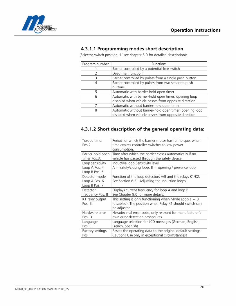
4.3.1.1 Programming modes short description (Selector switch position ‘1’ see chapter 5.0 for detailed description): Program number Function:
1 Barrier controlled by a potential-free switch 2 Dead man function 3 Barrier controlled by pulses from a single push button 4 Barrier controlled by pulses from two separate push
buttons 5 Automatic with barrier-hold open timer 6 Automatic with barrier-hold open timer, opening loop
disabled when vehicle passes from opposite direction 7 Automatic without barrier-hold open timer 8 Automatic without barrier-hold open timer, opening loop
disabled when vehicle passes from opposite direction
4.3.1.2 Short description of the general operating data: Torque time: Pos.2
Period for which the barrier motor has full torque, when time expires controller switches to low power consumption.
Barrier-hold open timer Pos.3:
Time after which the barrier closes automatically if no vehicle has passed through the safety device.
Loop sensitivity Loop A Pos. 4 Loop B Pos. 5
Inductive loop Sensitivity level A = safety/closing loop, B = opening / presence loop
Detector mode Loop A Pos. 6 Loop B Pos. 7
Function of the loop detectors A/B and the relays K1/K2. See Section 6.5: ‘Adjusting the induction loops’.
Detector frequency Pos. 8
Displays current frequency for loop A and loop B See Chapter 9.0 for more details.
K1 relay output Pos. B
This setting is only functioning when Mode Loop a = 0 (disabled). The position when Relay K1 should switch can be adjusted.
Hardware error Pos. D
Hexadecimal error code, only relevant for manufacturer’s own error detection procedures
Language Pos. E
Language selection for LCD messages (German, English, French, Spanish)
Factory settings Pos. F
Resets the operating data to the original default settings. Caution! Use only in exceptional circumstances!

Operation Instructions
MIB20_30_40 OPERATION MANUAL 2003_05 - 21 -
?
5.0 Programming Modes 1.0 To select a Programming mode turn the rotary switch in position 1.
Display Message:
2.0 To change to different Program Mode press and hold both, the black and the white button down. A cursor will appear below the number. Release both buttons. 3.0 When cursor appeared below the number use the black button to scroll through the available program modes. 4.0 When desired mode appeared on display press the white button. Display Message:
5.0 In order to save your changes press the Black button
Display Message: 6.0 To return to the normal operating mode turn rotary switch to Position 1
program number X
X = Selected Program mode number program number X
X = Current Program mode number

Operation Instructions
MIB20_30_40 OPERATION MANUAL 2003_05
22
5.1 Available Program Modes and functions Important note: The information provided here is based on the standard program S24008. Differences may exist to other standard programs or customized versions. These programs are documented and attached to this standard manual as addendum. To find out what software is currently installed please read chapter 17.1. All external equipment that uses the MLC* controller inputs (e.g. push buttons, light barriers, limit switches) must be connected as potential free contacts. Contact Magnetic for advice before connecting any equipment that doesn’t meet those requirements. Note: DO NOT CONNECT ANY DEVICE WHICH WOULD DELIVER ANY VOLTAGE OF ANY KIND TO THE INPUTS OF THE MLC* CONTROLLER. Note: External safety devices other then the internal loop A of the MLC* controller must be connected as normally closed contact to IN 5 (Terminal 32) and terminal 33 (+24VDC). If the internal loop A is used as safety device no additional wiring is necessary but a jumper wire between IN5 (terminal 32) and terminal 33 (+24VDC) is imperative. This jumper wire comes factory wired and loop A is active as safety device. Following are the functional descriptions of the available Program Modes
Operation Instructions
MIB20_30_40 OPERATION MANUAL 2003_05 - 23 -
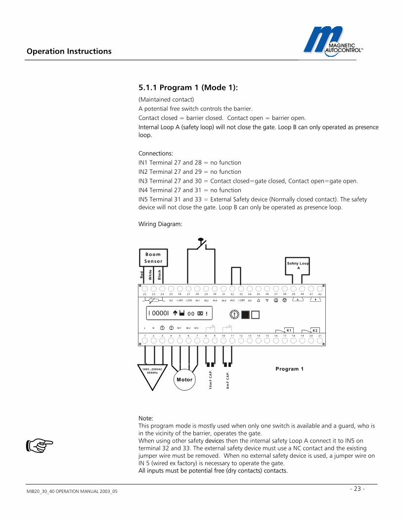
5.1.1 Program 1 (Mode 1): (Maintained contact) A potential free switch controls the barrier. Contact closed = barrier closed. Contact open = barrier open. Internal Loop A (safety loop) will not close the gate. Loop B can only operated as presence loop. Connections: IN1 Terminal 27 and 28 = no function IN2 Terminal 27 and 29 = no function IN3 Terminal 27 and 30 = Contact closed=gate closed, Contact open=gate open. IN4 Terminal 27 and 31 = no function IN5 Terminal 31 and 33 = External Safety device (Normally closed contact). The safety device will not close the gate. Loop B can only be operated as presence loop. Wiring Diagram: Note: This program mode is mostly used when only one switch is available and a guard, who is in the vicinity of the barrier, operates the gate. When using other safety devices then the internal safety Loop A connect it to IN5 on terminal 32 and 33. The external safety device must use a NC contact and the existing jumper wire must be removed. When no external safety device is used, a jumper wire on IN 5 (wired ex factory) is necessary to operate the gate. All inputs must be potential free (dry contacts) contacts.
10
mF
CA
P.
8m
F C
AP
.
B oomSensor
Red
Whi
te
Bla
ck
Motor
100V...250VAC50/60Hz
Program 1
Safety Loop A
M 1
IN 1 IN 2 IN 3 IN 4 IN 5
L N
0V 0V
M 2 M 3
272625242322 37363534333231302928 4241403938
A B
654321 16151413121110987 2120191817
K1 K2
bkrd
w h
00 !
CC
Operation Instructions
MIB20_30_40 OPERATION MANUAL 2003_05
24
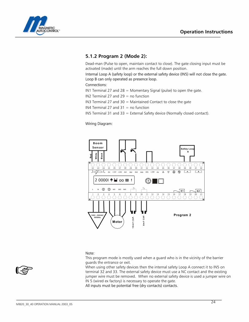
5.1.2 Program 2 (Mode 2): Dead-man (Pulse to open, maintain contact to close). The gate closing input must be activated (made) until the arm reaches the full down position. Internal Loop A (safety loop) or the external safety device (IN5) will not close the gate. Loop B can only operated as presence loop. Connections: IN1 Terminal 27 and 28 = Momentary Signal (pulse) to open the gate. IN2 Terminal 27 and 29 = no function IN3 Terminal 27 and 30 = Maintained Contact to close the gate IN4 Terminal 27 and 31 = no function IN5 Terminal 31 and 33 = External Safety device (Normally closed contact).
Wiring Diagram: Note: This program mode is mostly used when a guard who is in the vicinity of the barrier guards the entrance or exit. When using other safety devices then the internal safety Loop A connect it to IN5 on terminal 32 and 33. The external safety device must use a NC contact and the existing jumper wire must be removed. When no external safety device is used a jumper wire on IN 5 (wired ex factory) is necessary to operate the gate. All inputs must be potential free (dry contacts) contacts.
BoomSensor
Red
Whi
te
Bla
ck
Motor
100V...250VAC50/60Hz
Program 2
Safety Loop A
M1
IN1 IN2 IN3 IN4 IN5
L NC C
0V 0V
M2 M3
272625242322 37363534333231302928 4241403938
A B
654321 16151413121110987 2120191817
K1 K2
bkrd
wh
00 !
10
mF
CA
P.
8m
F C
AP
.
Operation Instructions
MIB20_30_40 OPERATION MANUAL 2003_05 - 25 -
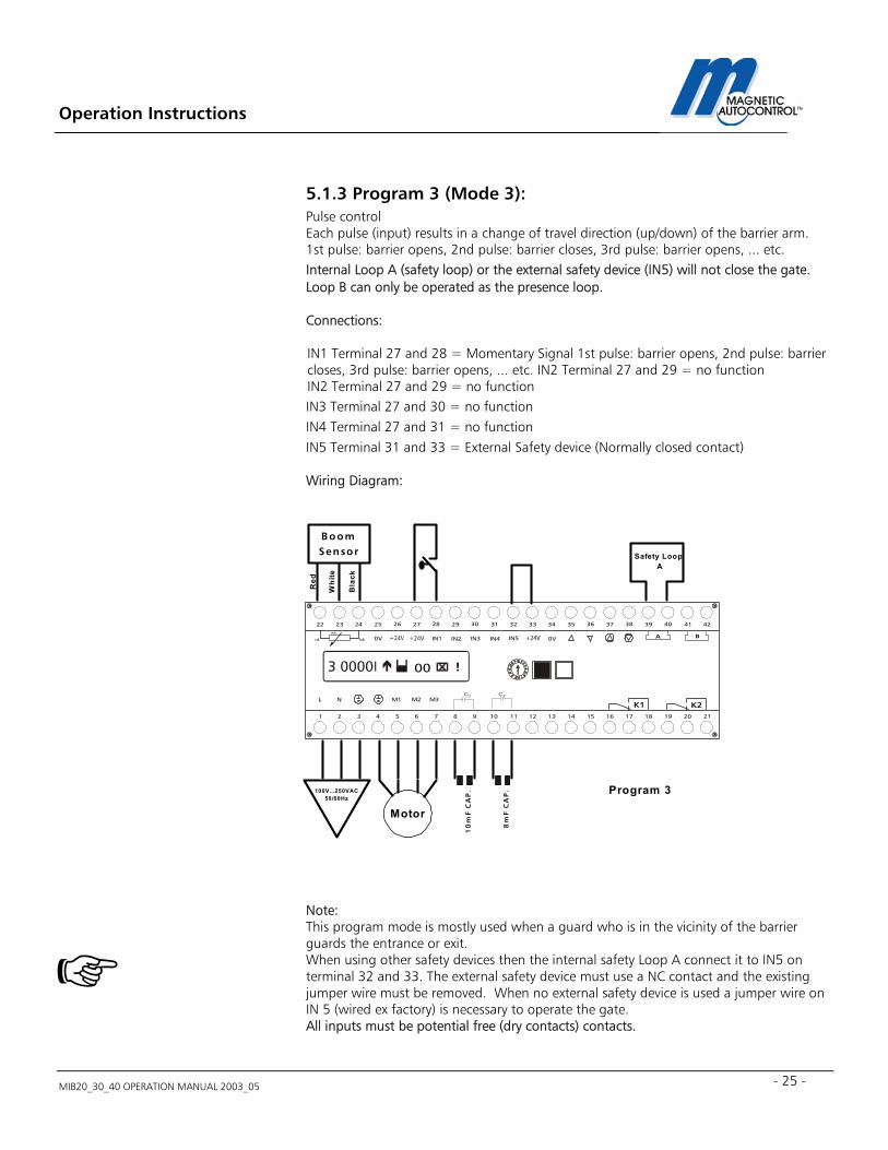
5.1.3 Program 3 (Mode 3): Pulse control Each pulse (input) results in a change of travel direction (up/down) of the barrier arm. 1st pulse: barrier opens, 2nd pulse: barrier closes, 3rd pulse: barrier opens, ... etc. Internal Loop A (safety loop) or the external safety device (IN5) will not close the gate. Loop B can only be operated as the presence loop. Connections: IN1 Terminal 27 and 28 = Momentary Signal 1st pulse: barrier opens, 2nd pulse: barrier closes, 3rd pulse: barrier opens, ... etc. IN2 Terminal 27 and 29 = no function IN2 Terminal 27 and 29 = no function IN3 Terminal 27 and 30 = no function IN4 Terminal 27 and 31 = no function IN5 Terminal 31 and 33 = External Safety device (Normally closed contact) Wiring Diagram: Note: This program mode is mostly used when a guard who is in the vicinity of the barrier guards the entrance or exit. When using other safety devices then the internal safety Loop A connect it to IN5 on terminal 32 and 33. The external safety device must use a NC contact and the existing jumper wire must be removed. When no external safety device is used a jumper wire on IN 5 (wired ex factory) is necessary to operate the gate. All inputs must be potential free (dry contacts) contacts.
BoomSensor
Red
Whi
te
Bla
ck
Motor
100V...250VAC50/60Hz
Program 3
Safety Loop A
M1
IN1 IN2 IN3 IN4 IN5
L NC C
0V 0V
M2 M3
272625242322 37363534333231302928 4241403938
A B
654321 16151413121110987 2120191817
K1 K2
bkrd
wh
00 !
10
mF
CA
P.
8m
F C
AP
.
Operation Instructions
MIB20_30_40 OPERATION MANUAL 2003_05
26
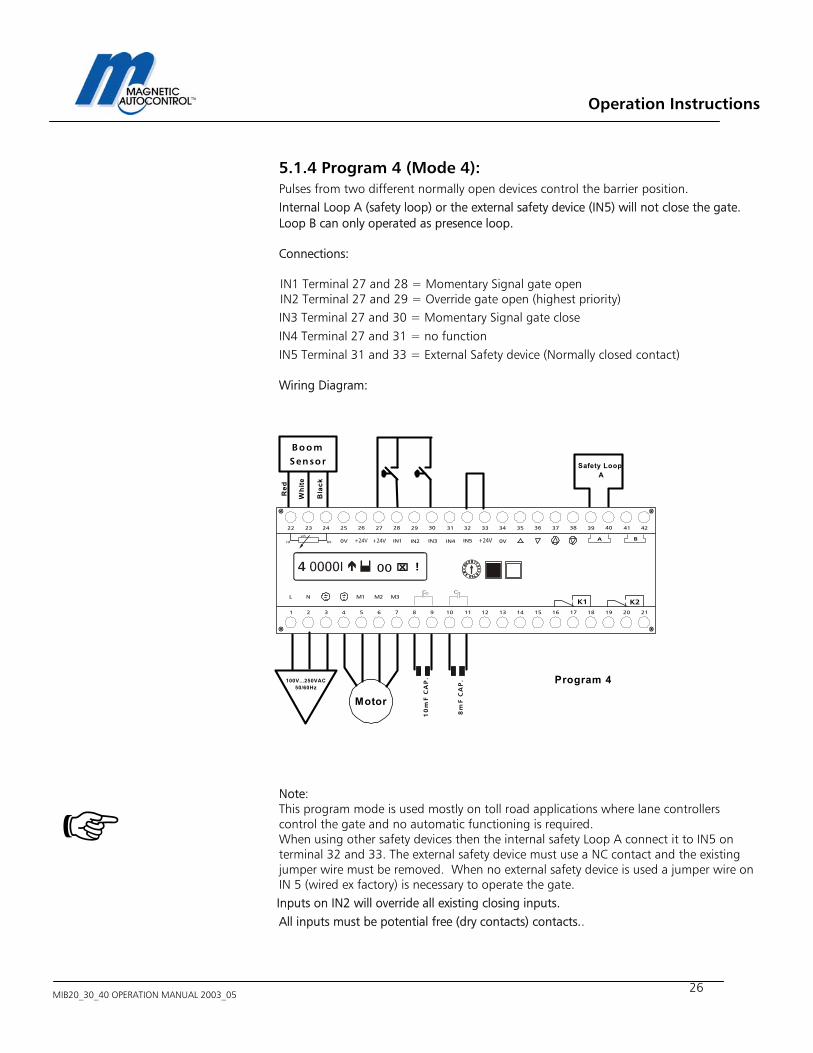
5.1.4 Program 4 (Mode 4): Pulses from two different normally open devices control the barrier position. Internal Loop A (safety loop) or the external safety device (IN5) will not close the gate. Loop B can only operated as presence loop. Connections: IN1 Terminal 27 and 28 = Momentary Signal gate open IN2 Terminal 27 and 29 = Override gate open (highest priority) IN3 Terminal 27 and 30 = Momentary Signal gate close IN4 Terminal 27 and 31 = no function IN5 Terminal 31 and 33 = External Safety device (Normally closed contact) Wiring Diagram: Note: This program mode is used mostly on toll road applications where lane controllers control the gate and no automatic functioning is required. When using other safety devices then the internal safety Loop A connect it to IN5 on terminal 32 and 33. The external safety device must use a NC contact and the existing jumper wire must be removed. When no external safety device is used a jumper wire on IN 5 (wired ex factory) is necessary to operate the gate.
Inputs on IN2 will override all existing closing inputs. All inputs must be potential free (dry contacts) contacts..
BoomSensor
Red
Whi
te
Bla
ck
Motor
100V...250VAC50/60Hz
Program 4
Safety Loop A
M1
IN1 IN2 IN3 IN4 IN5
L NC C
0V 0V
M2 M3
272625242322 37363534333231302928 4241403938
A B
654321 16151413121110987 2120191817
K1 K2
bkrd
wh
00 !
10
mF
CA
P.
8m
F C
AP
.
Operation Instructions
MIB20_30_40 OPERATION MANUAL 2003_05 - 27 -
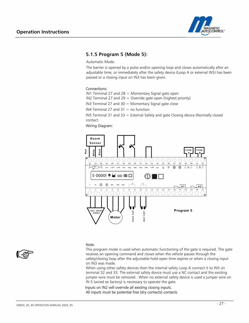
5.1.5 Program 5 (Mode 5): Automatic Mode. The barrier is opened by a pulse and/or opening loop and closes automatically after an adjustable time, or immediately after the safety device (Loop A or external IN5) has been passed or a closing input on IN3 has been given. Connections: IN1 Terminal 27 and 28 = Momentary Signal gate open IN2 Terminal 27 and 29 = Override gate open (highest priority) IN3 Terminal 27 and 30 = Momentary Signal gate close IN4 Terminal 27 and 31 = no function IN5 Terminal 31 and 33 = External Safety and gate Closing device (Normally closed contact. Wiring Diagram: Note: This program mode is used when automatic functioning of the gate is required. The gate receives an opening command and closes when the vehicle passes through the safety/closing loop after the adjustable hold-open time expires or when a closing input on IN3 was made. When using other safety devices then the internal safety Loop A connect it to IN5 on terminal 32 and 33. The external safety device must use a NC contact and the existing jumper wire must be removed. When no external safety device is used a jumper wire on IN 5 (wired ex factory) is necessary to operate the gate.
Inputs on IN2 will override all existing closing inputs. All inputs must be potential free (dry contacts) contacts
BoomSensor
Motor
Program 5
Loop A
M1
IN1 IN2 IN3 IN4 IN5
L NC C
0V 0V
M2 M3
272625242322 37363534333231302928 4241403938
A B
654321 16151413121110987 2120191817
K1 K2
bkrd
wh
00
10
mF
CA
P.
8m
F C
AP
.
Loop BR
ed
Whi
te
Bla
ck
100V...250VAC50/60Hz
Operation Instructions
MIB20_30_40 OPERATION MANUAL 2003_05
28
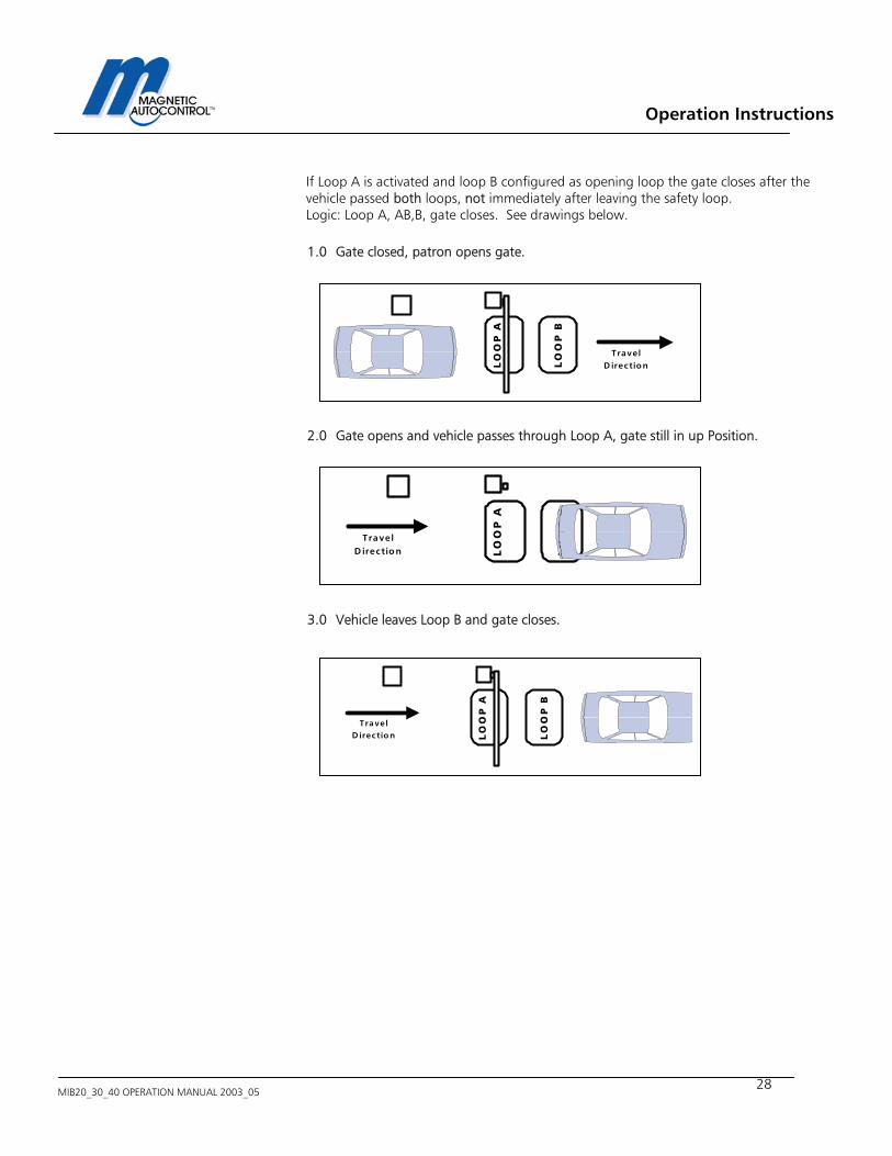
If Loop A is activated and loop B configured as opening loop the gate closes after the vehicle passed both loops, not immediately after leaving the safety loop. Logic: Loop A, AB,B, gate closes. See drawings below. 1.0 Gate closed, patron opens gate. 2.0 Gate opens and vehicle passes through Loop A, gate still in up Position.
3.0 Vehicle leaves Loop B and gate closes.
LO
OP
B
LO
OP
A
TravelD irection
LO
OP
B
LO
OP
A
TravelD irection
LO
OP
B
LO
OP
A
Trave lD irection
Operation Instructions
MIB20_30_40 OPERATION MANUAL 2003_05 - 29 -
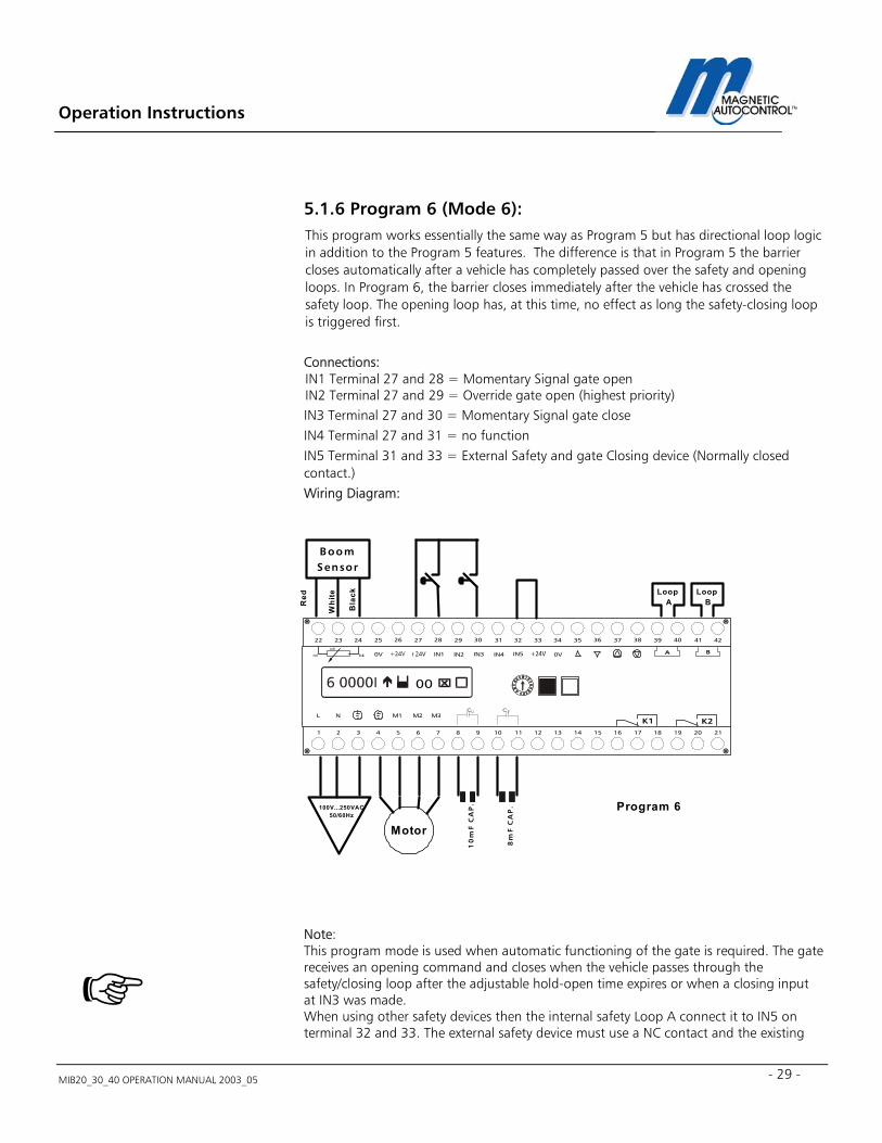
5.1.6 Program 6 (Mode 6): This program works essentially the same way as Program 5 but has directional loop logic in addition to the Program 5 features. The difference is that in Program 5 the barrier closes automatically after a vehicle has completely passed over the safety and opening loops. In Program 6, the barrier closes immediately after the vehicle has crossed the safety loop. The opening loop has, at this time, no effect as long the safety-closing loop is triggered first. Connections: IN1 Terminal 27 and 28 = Momentary Signal gate open IN2 Terminal 27 and 29 = Override gate open (highest priority) IN3 Terminal 27 and 30 = Momentary Signal gate close IN4 Terminal 27 and 31 = no function IN5 Terminal 31 and 33 = External Safety and gate Closing device (Normally closed contact.) Wiring Diagram: Note: This program mode is used when automatic functioning of the gate is required. The gate receives an opening command and closes when the vehicle passes through the safety/closing loop after the adjustable hold-open time expires or when a closing input at IN3 was made. When using other safety devices then the internal safety Loop A connect it to IN5 on terminal 32 and 33. The external safety device must use a NC contact and the existing
BoomSensor
Motor
Program 6
Loop A
M1
IN1 IN2 IN3 IN4 IN5
L NC C
0V 0V
M2 M3
272625242322 37363534333231302928 4241403938
A B
654321 16151413121110987 2120191817
K1 K2
bkrd
wh
00
10
mF
CA
P.
8m
F C
AP
.
Loop BR
ed
Whi
te
Bla
ck
100V...250VAC50/60Hz
Operation Instructions
MIB20_30_40 OPERATION MANUAL 2003_05
30
jumper wire must be removed. When no external safety device is used a jumper wire on IN 5 (wired ex factory) is necessary to operate the gate.
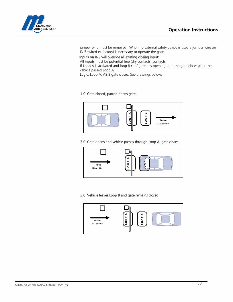
Inputs on IN2 will override all existing closing inputs. All inputs must be potential free (dry contacts) contacts If Loop A is activated and loop B configured as opening loop the gate closes after the vehicle passed Loop A Logic: Loop A, AB,B gate closes. See drawings below. 1.0 Gate closed, patron opens gate. 2.0 Gate opens and vehicle passes through Loop A, gate closes.
3.0 Vehicle leaves Loop B and gate remains closed.
LO
OP
B
LO
OP
A
TravelD irection
LO
OP
B
LO
OP
A
Trave lD irection
LO
OP
B
LO
OP
A
TravelD irection
Operation Instructions
MIB20_30_40 OPERATION MANUAL 2003_05 - 31 -
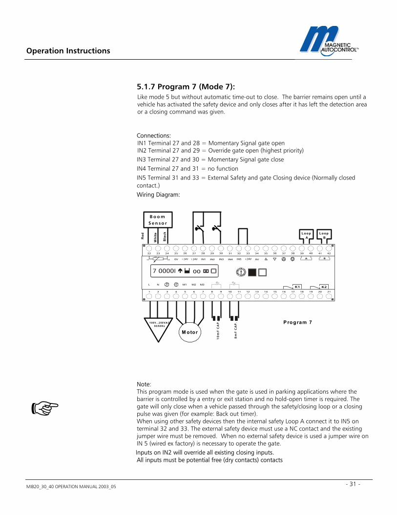
5.1.7 Program 7 (Mode 7): Like mode 5 but without automatic time-out to close. The barrier remains open until a vehicle has activated the safety device and only closes after it has left the detection area or a closing command was given. Connections: IN1 Terminal 27 and 28 = Momentary Signal gate open IN2 Terminal 27 and 29 = Override gate open (highest priority) IN3 Terminal 27 and 30 = Momentary Signal gate close IN4 Terminal 27 and 31 = no function IN5 Terminal 31 and 33 = External Safety and gate Closing device (Normally closed contact.) Wiring Diagram: Note: This program mode is used when the gate is used in parking applications where the barrier is controlled by a entry or exit station and no hold-open timer is required. The gate will only close when a vehicle passed through the safety/closing loop or a closing pulse was given (for example: Back out timer). When using other safety devices then the internal safety Loop A connect it to IN5 on terminal 32 and 33. The external safety device must use a NC contact and the existing jumper wire must be removed. When no external safety device is used a jumper wire on IN 5 (wired ex factory) is necessary to operate the gate.
Inputs on IN2 will override all existing closing inputs. All inputs must be potential free (dry contacts) contacts
B o o mS e n s o r
M otor
P rogram 7
Loop A
M1
IN1 IN2 IN3 IN4 IN5
L NC C
0V 0V
M2 M3
272625242322 37363534333231302928 4241403938
A B
654321 16151413121110987 2120191817
K1 K2
bkrd
wh
00
10
mF
CA
P.
8m
F C
AP
.Loop
BRed
Whi
te
Bla
ck
100V...250VA C50/60H z
Operation Instructions
MIB20_30_40 OPERATION MANUAL 2003_05
32
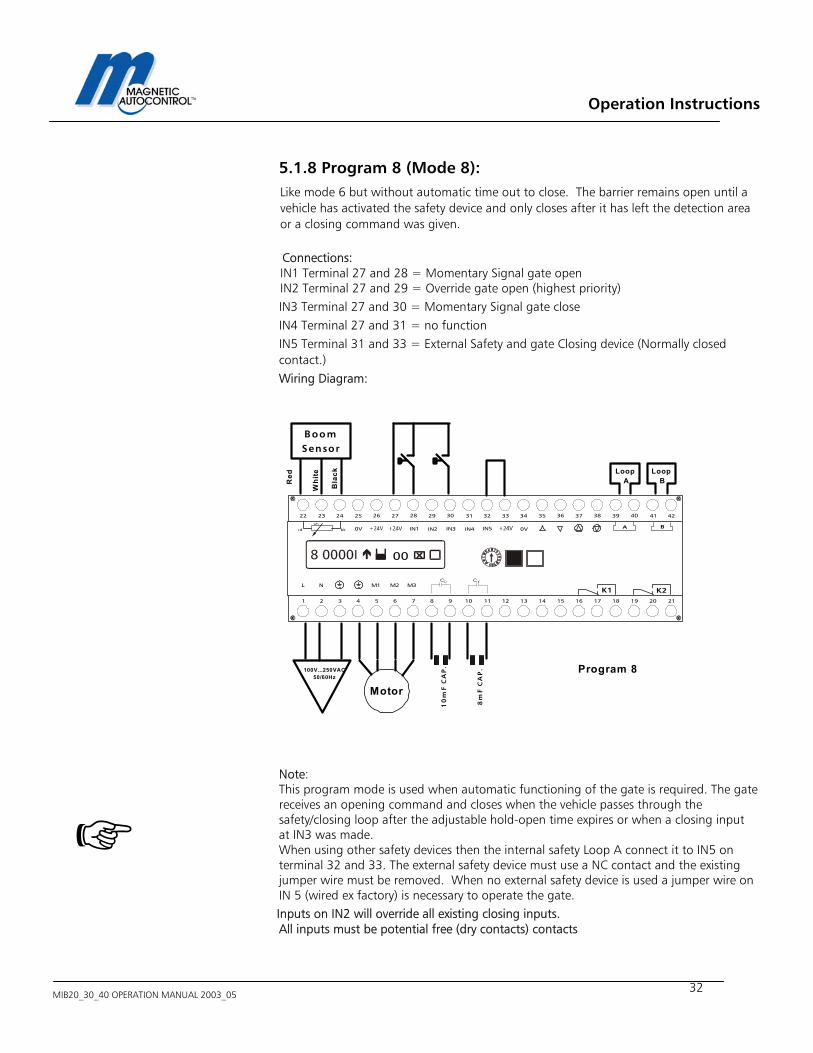
5.1.8 Program 8 (Mode 8): Like mode 6 but without automatic time out to close. The barrier remains open until a vehicle has activated the safety device and only closes after it has left the detection area or a closing command was given. Connections: IN1 Terminal 27 and 28 = Momentary Signal gate open IN2 Terminal 27 and 29 = Override gate open (highest priority) IN3 Terminal 27 and 30 = Momentary Signal gate close IN4 Terminal 27 and 31 = no function IN5 Terminal 31 and 33 = External Safety and gate Closing device (Normally closed contact.) Wiring Diagram: Note: This program mode is used when automatic functioning of the gate is required. The gate receives an opening command and closes when the vehicle passes through the safety/closing loop after the adjustable hold-open time expires or when a closing input at IN3 was made. When using other safety devices then the internal safety Loop A connect it to IN5 on terminal 32 and 33. The external safety device must use a NC contact and the existing jumper wire must be removed. When no external safety device is used a jumper wire on IN 5 (wired ex factory) is necessary to operate the gate.
Inputs on IN2 will override all existing closing inputs. All inputs must be potential free (dry contacts) contacts
BoomSensor
Motor
Program 8
Loop A
M1
IN1 IN2 IN3 IN4 IN5
L NC C
0V 0V
M2 M3
272625242322 37363534333231302928 4241403938
A B
654321 16151413121110987 2120191817
K1 K2
bkrd
wh
00
10
mF
CA
P.
8m
F C
AP
.Loop
BRed
Whi
te
Bla
ck
100V...250VAC50/60Hz
Operation Instructions
MIB20_30_40 OPERATION MANUAL 2003_05 - 33 -
?
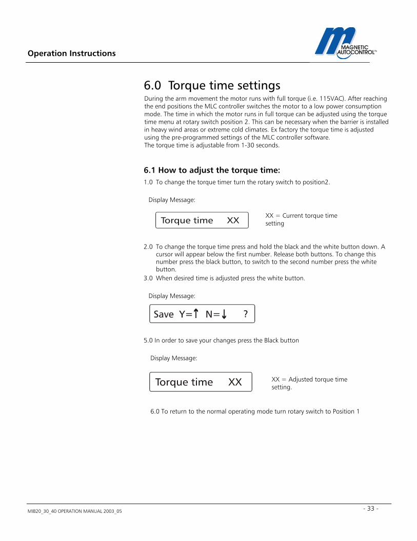
6.0 Torque time settings During the arm movement the motor runs with full torque (i.e. 115VAC). After reaching the end positions the MLC controller switches the motor to a low power consumption mode. The time in which the motor runs in full torque can be adjusted using the torque time menu at rotary switch position 2. This can be necessary when the barrier is installed in heavy wind areas or extreme cold climates. Ex factory the torque time is adjusted using the pre-programmed settings of the MLC controller software. The torque time is adjustable from 1-30 seconds.
6.1 How to adjust the torque time: 1.0 To change the torque timer turn the rotary switch to position2.
Display Message:
2.0 To change the torque time press and hold the black and the white button down. A
cursor will appear below the first number. Release both buttons. To change this number press the black button, to switch to the second number press the white button.
3.0 When desired time is adjusted press the white button. Display Message:
5.0 In order to save your changes press the Black button Display Message: 6.0 To return to the normal operating mode turn rotary switch to Position 1
XX = Adjusted torque time setting.
XX = Current torque time setting
Operation Instructions
MIB20_30_40 OPERATION MANUAL 2003_05
34
?
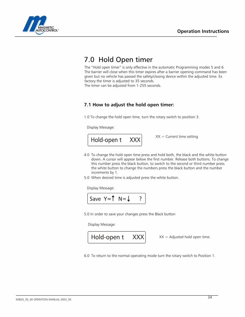
7.0 Hold Open timer The “Hold open timer” is only effective in the automatic Programming modes 5 and 6 The barrier will close when this timer expires after a barrier opening command has been given but no vehicle has passed the safety/closing device within the adjusted time. Ex factory the timer is adjusted to 35 seconds. The timer can be adjusted from 1-255 seconds.
7.1 How to adjust the hold open timer: 1.0 To change the hold open time, turn the rotary switch to position 3.
Display Message:
4.0 To change the hold open time press and hold both, the black and the white button
down. A cursor will appear below the first number. Release both buttons. To change this number press the black button, to switch to the second or third number press the white button to change the numbers press the black button and the number increments by 1.
5.0 When desired time is adjusted press the white button. Display Message:
5.0 In order to save your changes press the Black button Display Message:
6.0 To return to the normal operating mode turn the rotary switch to Position 1.
XX = Adjusted hold open time.
XX = Current time setting
Operation Instructions
MIB20_30_40 OPERATION MANUAL 2003_05 - 35 -
?
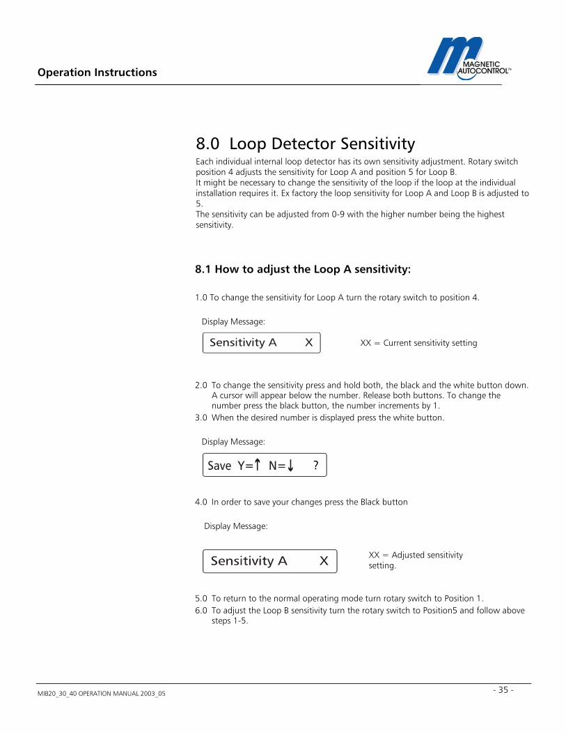
8.0 Loop Detector Sensitivity Each individual internal loop detector has its own sensitivity adjustment. Rotary switch position 4 adjusts the sensitivity for Loop A and position 5 for Loop B. It might be necessary to change the sensitivity of the loop if the loop at the individual installation requires it. Ex factory the loop sensitivity for Loop A and Loop B is adjusted to 5. The sensitivity can be adjusted from 0-9 with the higher number being the highest sensitivity.
8.1 How to adjust the Loop A sensitivity: 1.0 To change the sensitivity for Loop A turn the rotary switch to position 4.
Display Message:
2.0 To change the sensitivity press and hold both, the black and the white button down.
A cursor will appear below the number. Release both buttons. To change the number press the black button, the number increments by 1.
3.0 When the desired number is displayed press the white button. Display Message:
4.0 In order to save your changes press the Black button Display Message:
5.0 To return to the normal operating mode turn rotary switch to Position 1. 6.0 To adjust the Loop B sensitivity turn the rotary switch to Position5 and follow above
steps 1-5.
XX = Adjusted sensitivity setting.
XX = Current sensitivity setting
Operation Instructions
MIB20_30_40 OPERATION MANUAL 2003_05
36
?
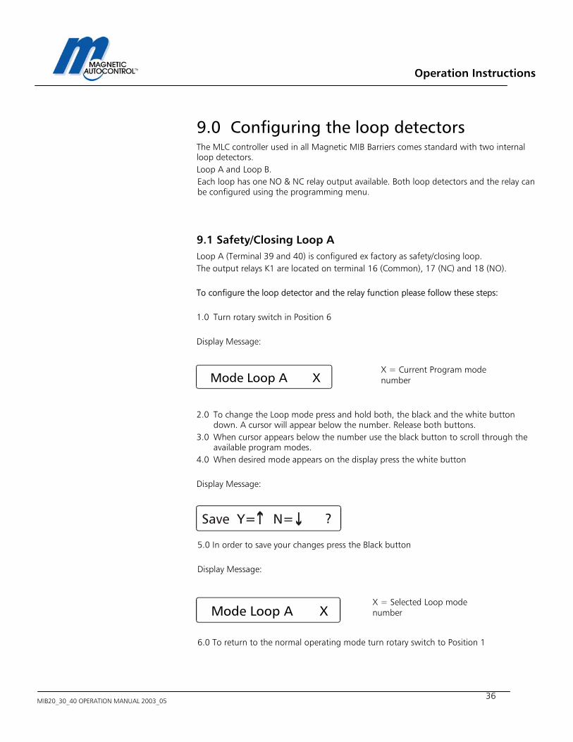
9.0 Configuring the loop detectors The MLC controller used in all Magnetic MIB Barriers comes standard with two internal loop detectors. Loop A and Loop B. Each loop has one NO & NC relay output available. Both loop detectors and the relay can be configured using the programming menu.
9.1 Safety/Closing Loop A Loop A (Terminal 39 and 40) is configured ex factory as safety/closing loop. The output relays K1 are located on terminal 16 (Common), 17 (NC) and 18 (NO). To configure the loop detector and the relay function please follow these steps: 1.0 Turn rotary switch in Position 6 Display Message: 2.0 To change the Loop mode press and hold both, the black and the white button
down. A cursor will appear below the number. Release both buttons. 3.0 When cursor appears below the number use the black button to scroll through the
available program modes. 4.0 When desired mode appears on the display press the white button Display Message:
5.0 In order to save your changes press the Black button
Display Message:
6.0 To return to the normal operating mode turn rotary switch to Position 1
Mode Loop A X
X = Current Program mode number
X = Selected Loop mode number Mode Loop A X
Operation Instructions
MIB20_30_40 OPERATION MANUAL 2003_05 - 37 -
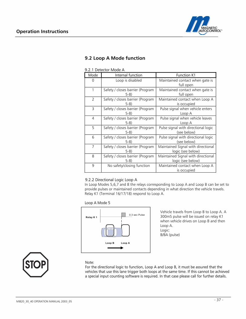
9.2 Loop A Mode function
9.2.1 Detector Mode A Mode Internal function Function K1
0 Loop is disabled Maintained contact when gate is full open
1 Safety / closes barrier (Program 5-8)
Maintained contact when gate is full open
2 Safety / closes barrier (Program 5-8)
Maintained contact when Loop A is occupied
3 Safety / closes barrier (Program 5-8)
Pulse signal when vehicle enters Loop A
4 Safety / closes barrier (Program 5-8)
Pulse signal when vehicle leaves Loop A
5 Safety / closes barrier (Program 5-8)
Pulse signal with directional logic (see below)
6 Safety / closes barrier (Program 5-8)
Pulse signal with directional logic (see below)
7 Safety / closes barrier (Program 5-8)
Maintained Signal with directional logic (see below)
8 Safety / closes barrier (Program 5-8)
Maintained Signal with directional logic (see below)
9 No safety/closing function Maintained contact when Loop A is occupied
9.2.2 Directional Logic Loop A In Loop Modes 5,6,7 and 8 the relays corresponding to Loop A and Loop B can be set to provide pulses or maintained contacts depending in what direction the vehicle travels. Relay K1 (Terminal 16/17/18) respond to Loop A. Loop A Mode 5 Note: For the directional logic to function, Loop A and Loop B, it must be assured that the vehicles that use this lane trigger both loops at the same time. If this cannot be achieved a special input counting software is required. In that case please call for further details.
Vehicle travels from Loop B to Loop A. A 300mS pulse will be issued on relay K1 when vehicle drives on Loop B and then Loop A. Logic: B/BA (pulse)
Loop B Loop A
Relay K 10.3 sec Pulse
Operation Instructions
MIB20_30_40 OPERATION MANUAL 2003_05
38
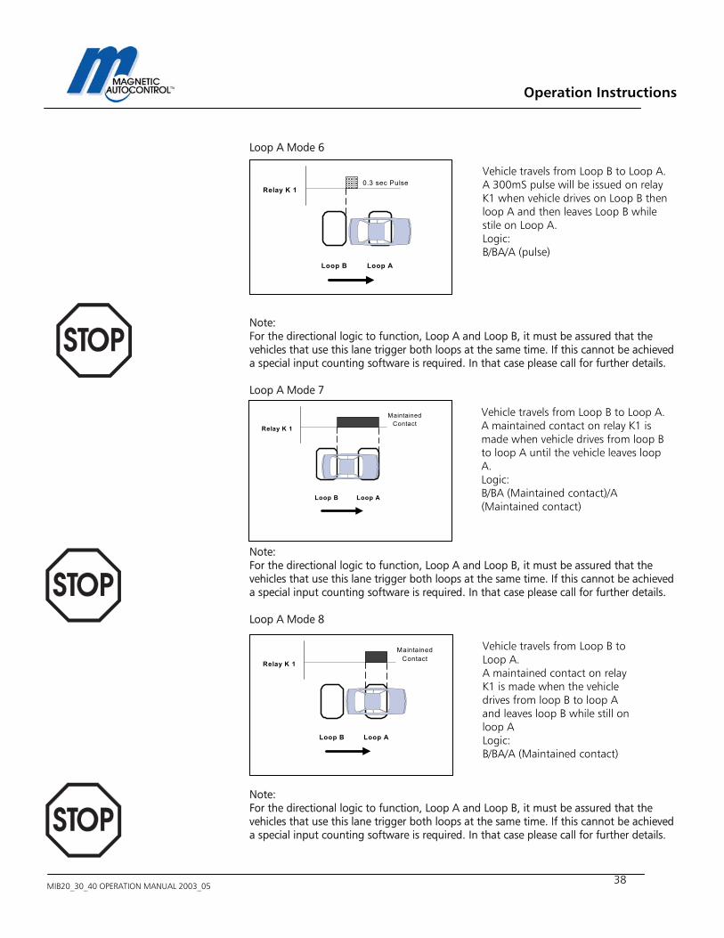
Loop A Mode 6 Note: For the directional logic to function, Loop A and Loop B, it must be assured that the vehicles that use this lane trigger both loops at the same time. If this cannot be achieved a special input counting software is required. In that case please call for further details. Loop A Mode 7 Note: For the directional logic to function, Loop A and Loop B, it must be assured that the vehicles that use this lane trigger both loops at the same time. If this cannot be achieved a special input counting software is required. In that case please call for further details. Loop A Mode 8
Note: For the directional logic to function, Loop A and Loop B, it must be assured that the vehicles that use this lane trigger both loops at the same time. If this cannot be achieved a special input counting software is required. In that case please call for further details.
Vehicle travels from Loop B to Loop A. A 300mS pulse will be issued on relay K1 when vehicle drives on Loop B then loop A and then leaves Loop B while stile on Loop A. Logic: B/BA/A (pulse)
Vehicle travels from Loop B to Loop A. A maintained contact on relay K1 is made when vehicle drives from loop B to loop A until the vehicle leaves loop A. Logic: B/BA (Maintained contact)/A (Maintained contact)
Loop B Loop A
Relay K 1
MaintainedContact
Vehicle travels from Loop B to Loop A. A maintained contact on relay K1 is made when the vehicle drives from loop B to loop A and leaves loop B while still on loop A Logic: B/BA/A (Maintained contact)
Loop B Loop A
Relay K 1
MaintainedContact
Loop B Loop A
Relay K 10.3 sec Pulse
Operation Instructions
MIB20_30_40 OPERATION MANUAL 2003_05 - 39 -
?
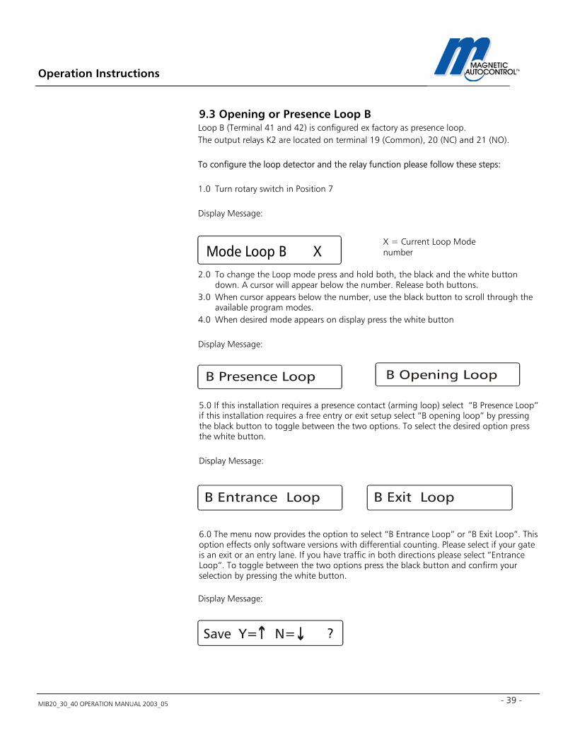
9.3 Opening or Presence Loop B Loop B (Terminal 41 and 42) is configured ex factory as presence loop. The output relays K2 are located on terminal 19 (Common), 20 (NC) and 21 (NO). To configure the loop detector and the relay function please follow these steps: 1.0 Turn rotary switch in Position 7 Display Message: 2.0 To change the Loop mode press and hold both, the black and the white button
down. A cursor will appear below the number. Release both buttons. 3.0 When cursor appears below the number, use the black button to scroll through the
available program modes. 4.0 When desired mode appears on display press the white button Display Message:
5.0 If this installation requires a presence contact (arming loop) select “B Presence Loop” if this installation requires a free entry or exit setup select “B opening loop” by pressing the black button to toggle between the two options. To select the desired option press the white button.
Display Message:
6.0 The menu now provides the option to select “B Entrance Loop” or “B Exit Loop”. This option effects only software versions with differential counting. Please select if your gate is an exit or an entry lane. If you have traffic in both directions please select “Entrance Loop”. To toggle between the two options press the black button and confirm your selection by pressing the white button. Display Message:
X = Current Loop Mode number
Mode Loop B X
Operation Instructions
MIB20_30_40 OPERATION MANUAL 2003_05
40
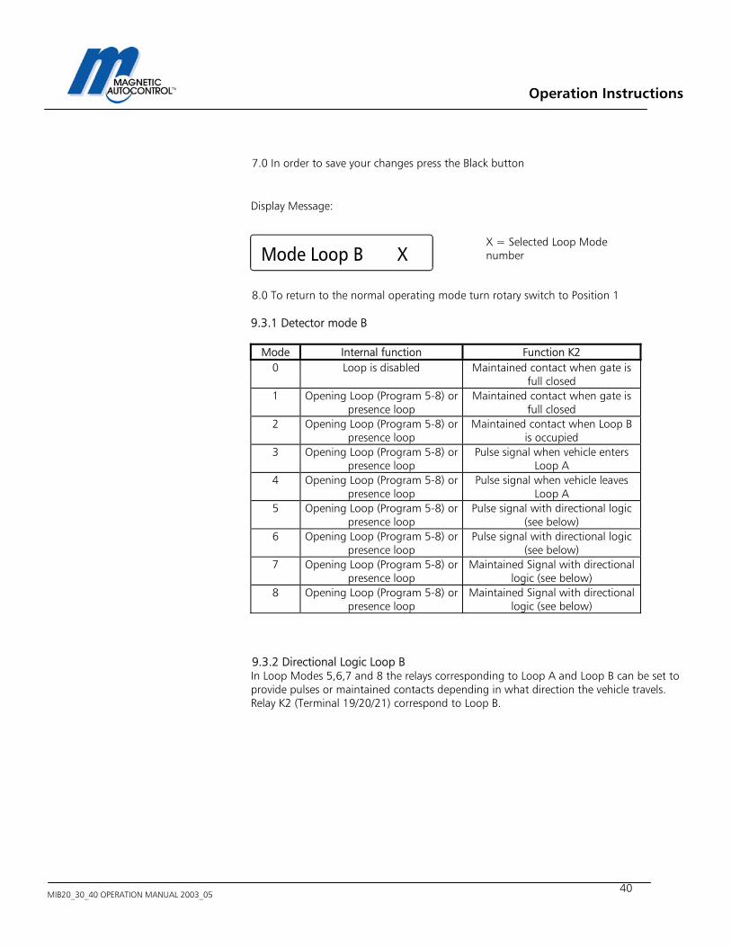
7.0 In order to save your changes press the Black button Display Message:
8.0 To return to the normal operating mode turn rotary switch to Position 1
9.3.1 Detector mode B
Mode Internal function Function K2
0 Loop is disabled Maintained contact when gate is full closed
1 Opening Loop (Program 5-8) or presence loop
Maintained contact when gate is full closed
2 Opening Loop (Program 5-8) or presence loop
Maintained contact when Loop B is occupied
3 Opening Loop (Program 5-8) or presence loop
Pulse signal when vehicle enters Loop A
4 Opening Loop (Program 5-8) or presence loop
Pulse signal when vehicle leaves Loop A
5 Opening Loop (Program 5-8) or presence loop
Pulse signal with directional logic (see below)
6 Opening Loop (Program 5-8) or presence loop
Pulse signal with directional logic (see below)
7 Opening Loop (Program 5-8) or presence loop
Maintained Signal with directional logic (see below)
8 Opening Loop (Program 5-8) or presence loop
Maintained Signal with directional logic (see below)
9.3.2 Directional Logic Loop B In Loop Modes 5,6,7 and 8 the relays corresponding to Loop A and Loop B can be set to provide pulses or maintained contacts depending in what direction the vehicle travels. Relay K2 (Terminal 19/20/21) correspond to Loop B.
X = Selected Loop Mode number
Mode Loop B X
Operation Instructions
MIB20_30_40 OPERATION MANUAL 2003_05 - 41 -
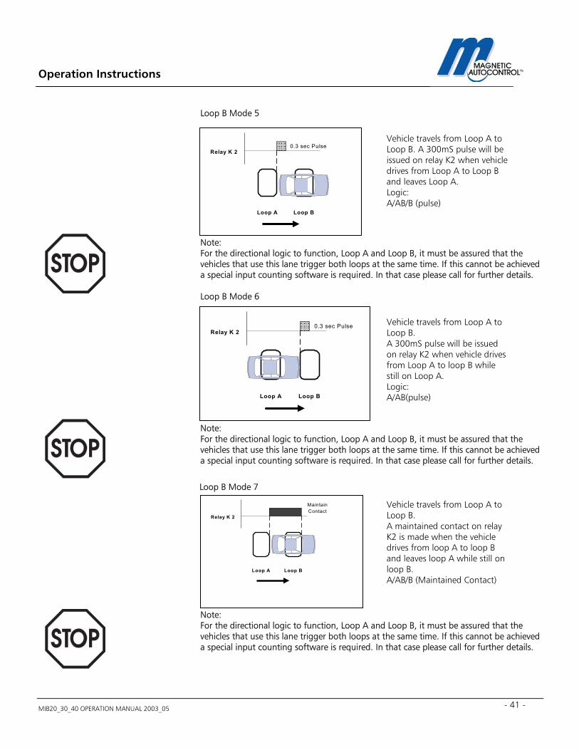
Loop B Mode 5 Note: For the directional logic to function, Loop A and Loop B, it must be assured that the vehicles that use this lane trigger both loops at the same time. If this cannot be achieved a special input counting software is required. In that case please call for further details. Loop B Mode 6 Note: For the directional logic to function, Loop A and Loop B, it must be assured that the vehicles that use this lane trigger both loops at the same time. If this cannot be achieved a special input counting software is required. In that case please call for further details. Loop B Mode 7 Note: For the directional logic to function, Loop A and Loop B, it must be assured that the vehicles that use this lane trigger both loops at the same time. If this cannot be achieved a special input counting software is required. In that case please call for further details.
Vehicle travels from Loop A to Loop B. A 300mS pulse will be issued on relay K2 when vehicle drives from Loop A to Loop B and leaves Loop A. Logic: A/AB/B (pulse)
Vehicle travels from Loop A to Loop B. A 300mS pulse will be issued on relay K2 when vehicle drives from Loop A to loop B while still on Loop A. Logic: A/AB(pulse)
Loop A Loop B
Relay K 2
MaintainContact
Vehicle travels from Loop A to Loop B. A maintained contact on relay K2 is made when the vehicle drives from loop A to loop B and leaves loop A while still on loop B. A/AB/B (Maintained Contact)
Loop A Loop B
Relay K 20.3 sec Pulse
Loop A Loop B
Relay K 20.3 sec Pulse
Operation Instructions
MIB20_30_40 OPERATION MANUAL 2003_05
42
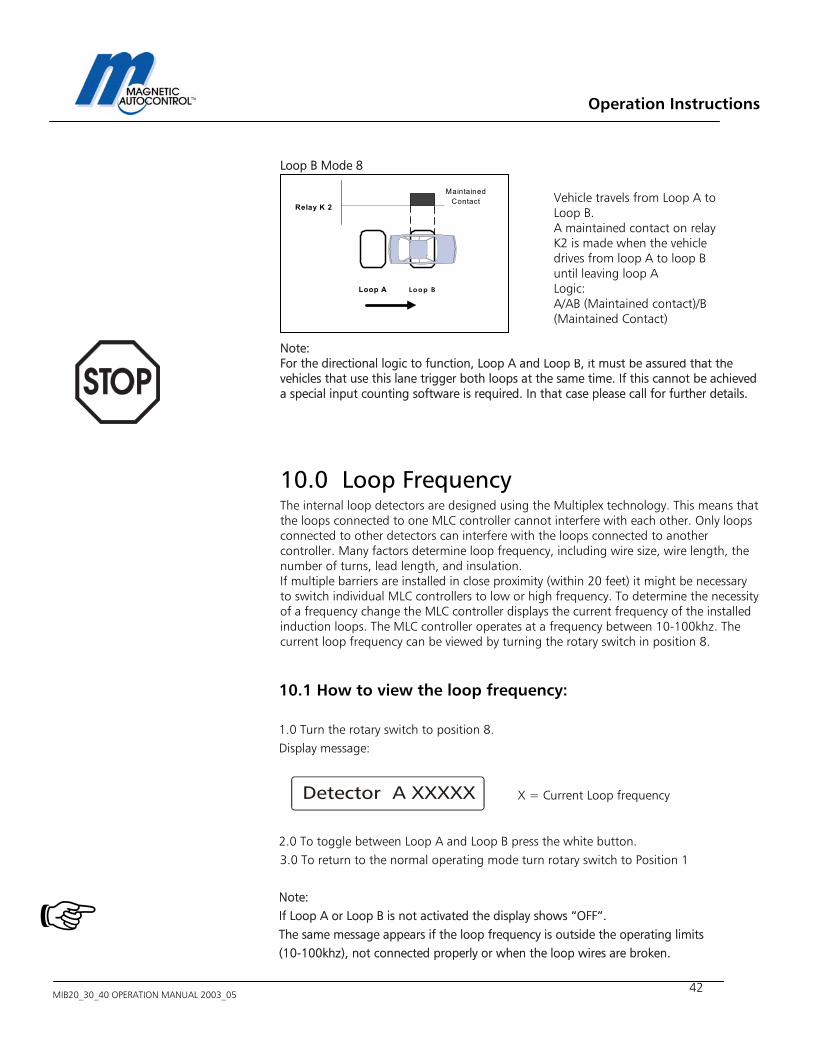
Loop B Mode 8 Note: For the directional logic to function, Loop A and Loop B, it must be assured that the vehicles that use this lane trigger both loops at the same time. If this cannot be achieved a special input counting software is required. In that case please call for further details.
10.0 Loop Frequency The internal loop detectors are designed using the Multiplex technology. This means that the loops connected to one MLC controller cannot interfere with each other. Only loops connected to other detectors can interfere with the loops connected to another controller. Many factors determine loop frequency, including wire size, wire length, the number of turns, lead length, and insulation. If multiple barriers are installed in close proximity (within 20 feet) it might be necessary to switch individual MLC controllers to low or high frequency. To determine the necessity of a frequency change the MLC controller displays the current frequency of the installed induction loops. The MLC controller operates at a frequency between 10-100khz. The current loop frequency can be viewed by turning the rotary switch in position 8.
10.1 How to view the loop frequency: 1.0 Turn the rotary switch to position 8. Display message: 2.0 To toggle between Loop A and Loop B press the white button. 3.0 To return to the normal operating mode turn rotary switch to Position 1 Note: If Loop A or Loop B is not activated the display shows “OFF”. The same message appears if the loop frequency is outside the operating limits (10-100khz), not connected properly or when the loop wires are broken.
Loop A Loop B
Relay K 2
MaintainedContact
Vehicle travels from Loop A to Loop B. A maintained contact on relay K2 is made when the vehicle drives from loop A to loop B until leaving loop A Logic: A/AB (Maintained contact)/B (Maintained Contact)
X = Current Loop frequency
Operation Instructions
MIB20_30_40 OPERATION MANUAL 2003_05 - 43 -
The frequency display can be used to determine what might be the cause of loop cross talking and can also be used to prevent it from happening. The frequencies of two loops that use different detectors (not connected to the same MLC controller) must be at least 3kHz (3000Hz) apart.
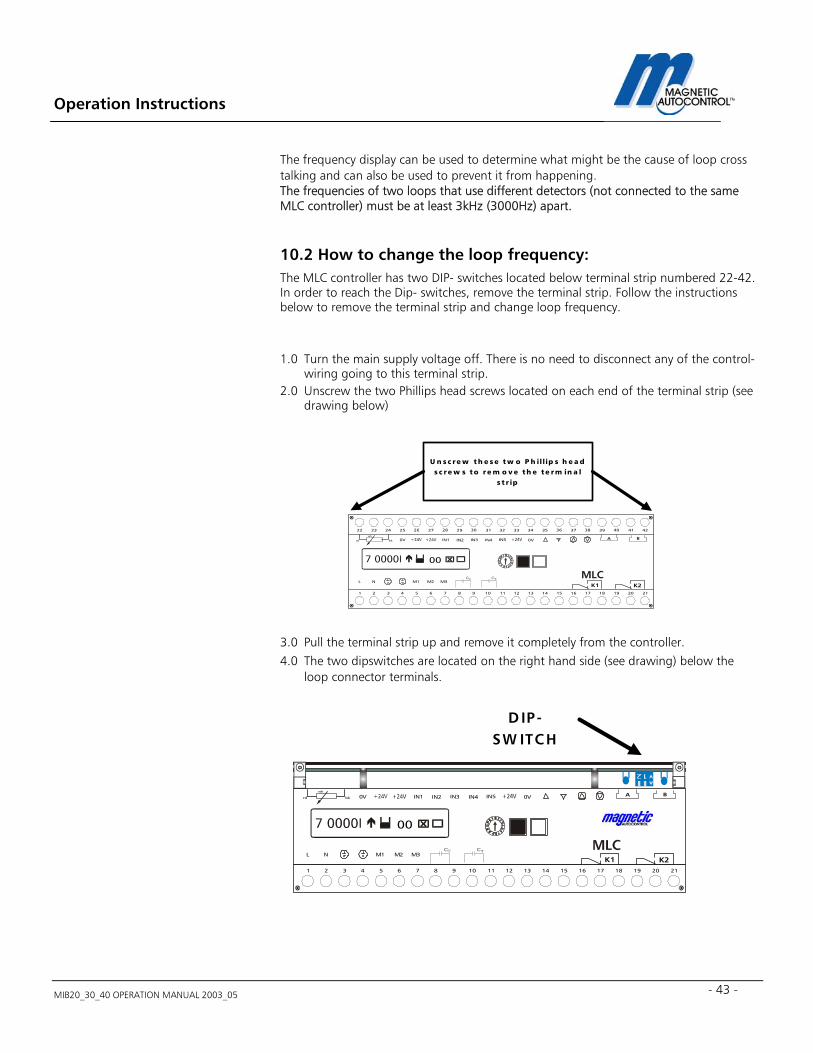
10.2 How to change the loop frequency: The MLC controller has two DIP- switches located below terminal strip numbered 22-42. In order to reach the Dip- switches, remove the terminal strip. Follow the instructions below to remove the terminal strip and change loop frequency.
1.0 Turn the main supply voltage off. There is no need to disconnect any of the control-
wiring going to this terminal strip. 2.0 Unscrew the two Phillips head screws located on each end of the terminal strip (see
drawing below) 3.0 Pull the terminal strip up and remove it completely from the controller. 4.0 The two dipswitches are located on the right hand side (see drawing) below the
loop connector terminals.
D IP-SW ITCH
M1
IN1 IN2 IN3 IN4 IN5
L NC C
0V 0V
M2 M3
A B
654321 16151413121110987 2120191817
K1 K2
bkrd
wh
00
M1
IN1 IN2 IN3 IN4 IN5
L NC C
0V 0V
M2 M3
272625242322 37363534333231302928 4241403938
A B
654321 16151413121110987 2120191817
K1 K2
bkrd
wh
00
U n s c re w t h e s e t w o P h il lip s h e a ds c re w s to r e m o v e th e te rm in a l
s t r ip
Operation Instructions
MIB20_30_40 OPERATION MANUAL 2003_05
44
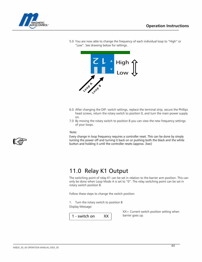
5.0 You are now able to change the frequency of each individual loop to “High” or “Low”. See drawing below for settings.
6.0 After changing the DIP- switch settings, replace the terminal strip, secure the Phillips head screws, return the rotary switch to position 0, and turn the main power supply on.
7.0 By moving the rotary switch to position 8 you can view the new frequency settings of your loops.
Note: Every change in loop frequency requires a controller reset. This can be done by simply turning the power off and turning it back on or pushing both the black and the white button and holding it until the controller resets (approx. 3sec)
11.0 Relay K1 Output The switching point of relay K1 can be set in relation to the barrier arm position. This can only be done when Loop Mode A is set to “0”. The relay switching point can be set in rotary switch position B. Follow these steps to change the switch position: 1. Turn the rotary switch to position B Display Message:
High
Low
Loop A
Loop B
1 - switch on XX
XX= Current switch position setting when barrier goes up.
Operation Instructions
MIB20_30_40 OPERATION MANUAL 2003_05 - 45 -
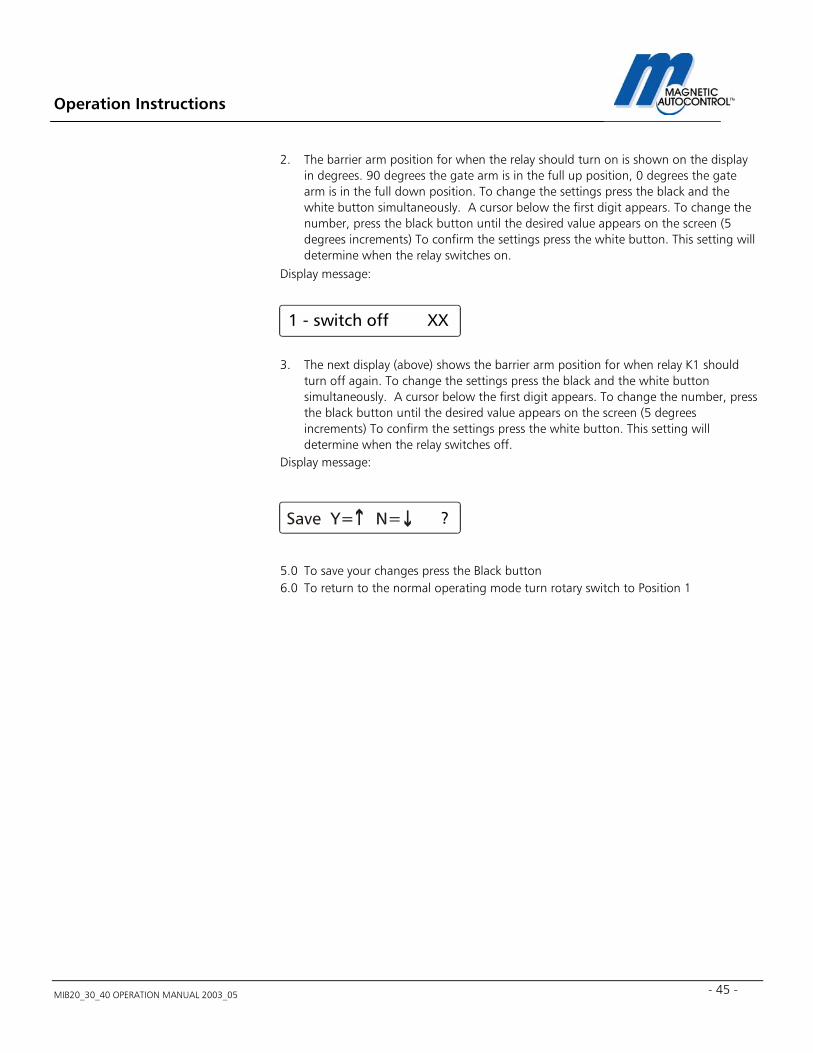
2. The barrier arm position for when the relay should turn on is shown on the display in degrees. 90 degrees the gate arm is in the full up position, 0 degrees the gate arm is in the full down position. To change the settings press the black and the white button simultaneously. A cursor below the first digit appears. To change the number, press the black button until the desired value appears on the screen (5 degrees increments) To confirm the settings press the white button. This setting will determine when the relay switches on.
Display message:
3. The next display (above) shows the barrier arm position for when relay K1 should turn off again. To change the settings press the black and the white button simultaneously. A cursor below the first digit appears. To change the number, press the black button until the desired value appears on the screen (5 degrees increments) To confirm the settings press the white button. This setting will determine when the relay switches off.
Display message:
5.0 To save your changes press the Black button 6.0 To return to the normal operating mode turn rotary switch to Position 1
1 - switch off XX
?

Operation Instructions
MIB20_30_40 OPERATION MANUAL 2003_05
46
12.0 Error Code The MLC controller comes with an error display feature that allows the user to determine internal controller errors. This Error is displayed as a hexadecimal code, which can be viewed by turning the rotary switch to position D. For the field technician only one error code is relevant: Display message: If the above error message is displayed the controller lost its boom sensor position and needs to be readjusted (see chapter 22.1 for readjusting the sensor). For all other error messages please call Magnetic Automation Corp. for technical support.
13.0 Language Setting The MLC controller can be set to multiple languages. Following are the pre-programmed standard languages: English= English Deutsch = German Francais = French Espanol = Spanish Move the rotary switch to position E to select the language of your choice. 1.0 Turn the rotary switch to position E Display Message:
2.0 To change the language, press both the black and the white button at the same
time. A cursor will appear at the last digit to the right. 3.0 Pressing the black button will change the display language. 4.0 To select a new language press the white button Display message: 5.0 To save your selection, press the black button. 6.0 Return the rotary switch to position 0 for normal operation.
?

Operation Instructions
MIB20_30_40 OPERATION MANUAL 2003_05 - 47 -
14.0 Default Settings The controller can be reset to original manufacturer default settings. By doing so all programmed settings are erased. To set the controller to its original manufacturer setting turn the rotary switch to position F. Press the black and white button, release. Press the black button to set the controller to default.
Operation Instructions
MIB20_30_40 OPERATION MANUAL 2003_05
48
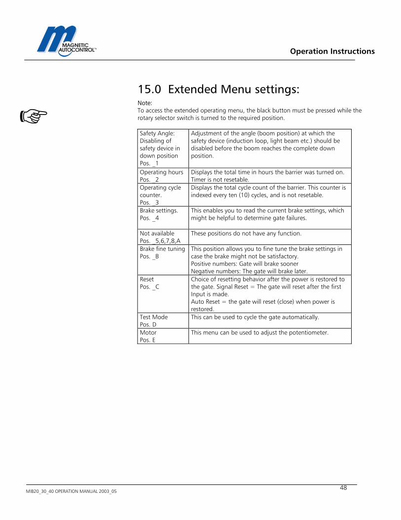
15.0 Extended Menu settings: Note: To access the extended operating menu, the black button must be pressed while the rotary selector switch is turned to the required position. Safety Angle: Disabling of safety device in down position Pos. _1
Adjustment of the angle (boom position) at which the safety device (induction loop, light beam etc.) should be disabled before the boom reaches the complete down position.
Operating hours Pos. _2
Displays the total time in hours the barrier was turned on. Timer is not resetable.
Operating cycle counter. Pos. _3
Displays the total cycle count of the barrier. This counter is indexed every ten (10) cycles, and is not resetable.
Brake settings. Pos. _4
This enables you to read the current brake settings, which might be helpful to determine gate failures.
Not available Pos. _5,6,7,8,A
These positions do not have any function.
Brake fine tuning Pos. _B
This position allows you to fine tune the brake settings in case the brake might not be satisfactory. Positive numbers: Gate will brake sooner Negative numbers: The gate will brake later.
Reset Pos. _C
Choice of resetting behavior after the power is restored to the gate. Signal Reset = The gate will reset after the first Input is made. Auto Reset = the gate will reset (close) when power is restored.
Test Mode Pos. D
This can be used to cycle the gate automatically.
Motor Pos. E
This menu can be used to adjust the potentiometer.
Operation Instructions
MIB20_30_40 OPERATION MANUAL 2003_05 - 49 -
15.1 Adjusting the safety angle: This setting allows the user to adjust the boom position in which the controller disables the safety devices. This setting allows the user to increase the safety of the operation or prevent tail gating from happening. To increase safety, the cut off angle is smaller; to prevent tail gating, the cut of angle is higher (i.e. the safety device is disabled sooner). To disable the safety cut off sooner to prevent tailgating will also increase the possibility that vehicles are being hit by the gate arm. This angle is adjustable between 10°- 80° in 5° increments. The down position equals 0° and the complete up position 90°. To change the setting follow steps below. 1.0 Press and hold the black button while turning the rotary switch to position 1 Display Message: 2.0 Press the black and the white button simultaneously. A cursor below the first digit
appears. To change the number, press the black button. To confirm the settings press the white button.
Display Message: 3.0 Press the black button to save the changes. 4.0 Return the rotary switch to position 0 for normal operation.
X = Current setting
?
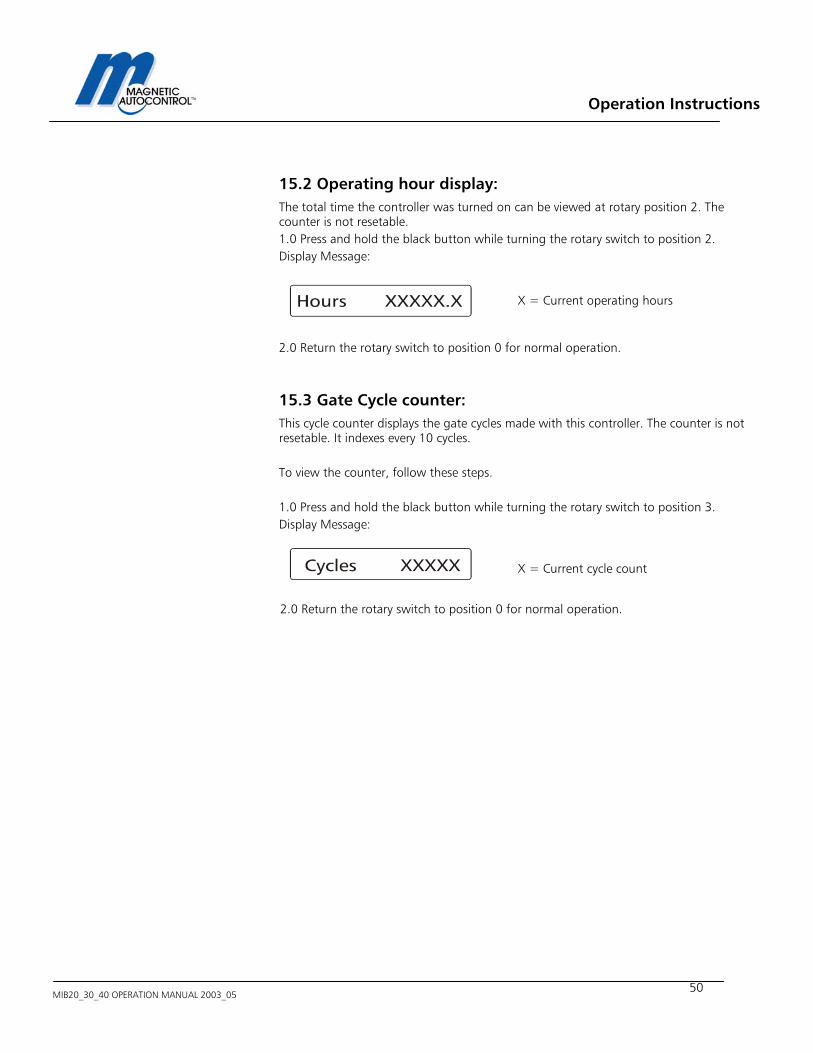
Operation Instructions
MIB20_30_40 OPERATION MANUAL 2003_05
50
15.2 Operating hour display: The total time the controller was turned on can be viewed at rotary position 2. The counter is not resetable. 1.0 Press and hold the black button while turning the rotary switch to position 2. Display Message: 2.0 Return the rotary switch to position 0 for normal operation.
15.3 Gate Cycle counter: This cycle counter displays the gate cycles made with this controller. The counter is not resetable. It indexes every 10 cycles. To view the counter, follow these steps. 1.0 Press and hold the black button while turning the rotary switch to position 3. Display Message: 2.0 Return the rotary switch to position 0 for normal operation.
X = Current operating hours
X = Current cycle count
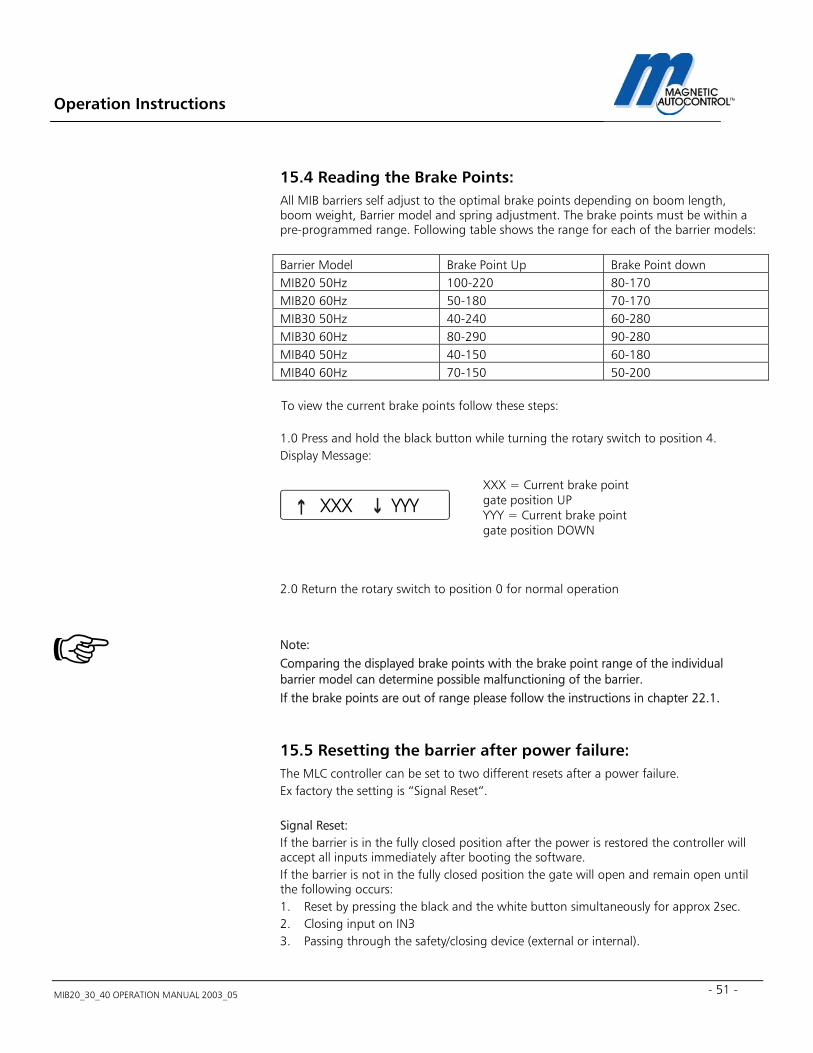
Operation Instructions
MIB20_30_40 OPERATION MANUAL 2003_05 - 51 -
15.4 Reading the Brake Points: All MIB barriers self adjust to the optimal brake points depending on boom length, boom weight, Barrier model and spring adjustment. The brake points must be within a pre-programmed range. Following table shows the range for each of the barrier models: Barrier Model Brake Point Up Brake Point down MIB20 50Hz 100-220 80-170 MIB20 60Hz 50-180 70-170 MIB30 50Hz 40-240 60-280 MIB30 60Hz 80-290 90-280 MIB40 50Hz 40-150 60-180 MIB40 60Hz 70-150 50-200 To view the current brake points follow these steps: 1.0 Press and hold the black button while turning the rotary switch to position 4. Display Message:
2.0 Return the rotary switch to position 0 for normal operation Note: Comparing the displayed brake points with the brake point range of the individual barrier model can determine possible malfunctioning of the barrier. If the brake points are out of range please follow the instructions in chapter 22.1.
15.5 Resetting the barrier after power failure: The MLC controller can be set to two different resets after a power failure. Ex factory the setting is “Signal Reset”. Signal Reset: If the barrier is in the fully closed position after the power is restored the controller will accept all inputs immediately after booting the software. If the barrier is not in the fully closed position the gate will open and remain open until the following occurs: 1. Reset by pressing the black and the white button simultaneously for approx 2sec. 2. Closing input on IN3 3. Passing through the safety/closing device (external or internal).
XXX = Current brake point gate position UP YYY = Current brake point gate position DOWN
XXX YYY
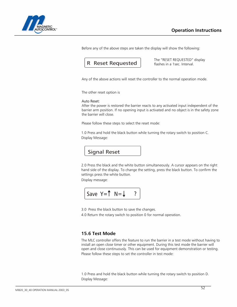
Operation Instructions
MIB20_30_40 OPERATION MANUAL 2003_05
52
Before any of the above steps are taken the display will show the following:
Any of the above actions will reset the controller to the normal operation mode. The other reset option is Auto Reset: After the power is restored the barrier reacts to any activated input independent of the barrier arm position. If no opening input is activated and no object is in the safety zone the barrier will close. Please follow these steps to select the reset mode: 1.0 Press and hold the black button while turning the rotary switch to position C. Display Message: 2.0 Press the black and the white button simultaneously. A cursor appears on the right hand side of the display. To change the setting, press the black button. To confirm the settings press the white button. Display message: 3.0 Press the black button to save the changes. 4.0 Return the rotary switch to position 0 for normal operation.
15.6 Test Mode The MLC controller offers the feature to run the barrier in a test mode without having to install an open close timer or other equipment. During this test mode the barrier will open and close continuously. This can be used for equipment demonstration or testing. Please follow these steps to set the controller in test mode: 1.0 Press and hold the black button while turning the rotary switch to position D. Display Message:
The “RESET REQUESTED” display flashes in a 1sec. Interval.
?
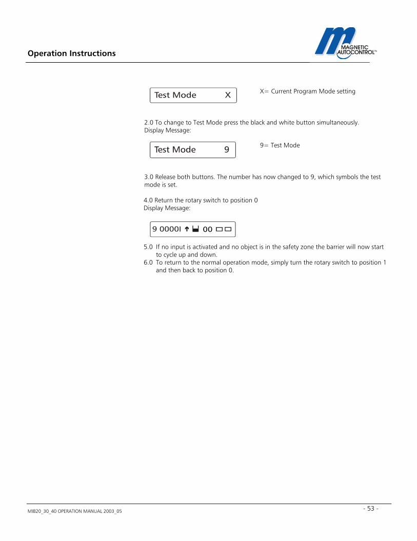
Operation Instructions
MIB20_30_40 OPERATION MANUAL 2003_05 - 53 -
2.0 To change to Test Mode press the black and white button simultaneously. Display Message: 3.0 Release both buttons. The number has now changed to 9, which symbols the test mode is set. 4.0 Return the rotary switch to position 0 Display Message: 5.0 If no input is activated and no object is in the safety zone the barrier will now start
to cycle up and down. 6.0 To return to the normal operation mode, simply turn the rotary switch to position 1
and then back to position 0.
X= Current Program Mode setting
9= Test Mode
00
Operation Instructions
MIB20_30_40 OPERATION MANUAL 2003_05
54
16.0 Installing the Induction Loops
16.1 General induction loop functionality The Loop detectors operate on the principle of inductance. The detector monitors an insulated electrical wire, placed on or below the road surface (LOOP). Any metallic object, such as a car, which passes through the field will absorb electromagnetic energy and simultaneously decrease the inductance and increase the resonant frequency of the loop. For most conventional installations, when the inductance or frequency changes beyond a preset threshold in the detector electronics, the detector indicates that a vehicle has been detected. Note: Only metallic objects can be detected. The loop frequency change depends on the size and form of the to be monitored object (i.e. car) not on the material mass, which does not influence the loop. The micro controller system self adjusts to the connected loop. Many factors determine loop inductance, including wire size, wire length, the number of turns, lead length, and insulation. Changes in loop inductance due to temperature or aging are automatically compensated. Detectors with multiple channels (i.e. dual channel) are monitored using the MULTIPLEX METHOD, which eliminates the interference (cross-talk) between the loops connected to this detector.
16.2 Loop Inductance
16.2.1 Inductance
Inductance is the resistance to the change of current flow. When a current is applied to a conductor (wire) a magnetic field is formed around the conductor (wire). If the current source is removed, the magnetic field collapses into the wire trying to maintain the current flow. By winding several turns of the wire into a coil, the magnetic field is intensified which increases the inductance. The loop inductance can be measured with an inductivity meter. The unit of measurements is the Henry (h). The inductance depends on the loop perimeter and number of turns. A bigger loop with more turns has a higher Inductance.
Operation Instructions
MIB20_30_40 OPERATION MANUAL 2003_05 - 55 -
16.2.2 Vehicle detection When a vehicle enters the loop the body and frame provide a conductive path for the magnetic field; causing a loading effect, which in turn causes the loop inductance to decrease. The decreased inductance causes the resonant frequency to increase from the nominal value. If the frequency change exceeds the threshold set by the sensitivity setting, the detector module will output a detect signal. There has been a misconception that an inductive loop requires a mass of metal for detection. Placing a single wire around the perimeter of the loop and shorting the ends together will quickly disprove the misconception. The single wire forming a shorted turn provides a current path for the magnetic field; thus causing a loading effect similar to that of a vehicle. The shorted turn effect of the single wire coil in the proximity of the loop acts much like a shorted turn secondary of a transformer.
16.2.3 Wire Turns required for loops The Inductive loop detectors will tune from 70 µH to 500 µH (µH = microHenry). It is preferable that the loop and lead-in have a minimum of approximately 70 µH for stability. The loop inductance should be equal to or greater than the lead-in inductance. If the inductance of the loop exceeds the requirements above, a proper functioning of the detector cannot be guaranteed. The loop inductance also influences the loop sensitivity. The best results are between 100 and 300 µH.
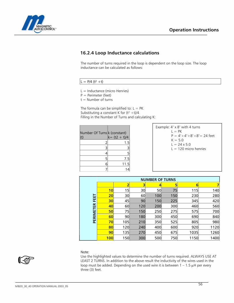
Operation Instructions
MIB20_30_40 OPERATION MANUAL 2003_05
56
16.2.4 Loop Inductance calculations
The number of turns required in the loop is dependent on the loop size. The loop inductance can be calculated as follows:
L = P/4 (t² +t)
L = Inductance (micro Henries) P = Perimeter (feet) t = Number of turns The formula can be simplified to: L = PK Substituting a constant K for (t² +t)/4 Filling in the Number of Turns and calculating K:
Note: Use the highlighted values to determine the number of turns required. ALWAYS USE AT LEAST 2 TURNS. In addition to the above result the inductivity of the wires used in the loop must be added. Depending on the used wire it is between 1 – 1.5 µH per every three (3) feet.
Example: 4’ x 8’ with 4 turns L = PK P = 4’+4’+8’+8’= 24 feet K = 5.0 L = 24 x 5.0 L = 120 micro henries
Number Of Turns(t)
k (constant) k= (t2 + t)/4
2 1.53 34 55 7.56 11.57 14
NUMBER OF TURNS 2 3 4 5 6 7
10 15 30 50 75 115 14020 30 60 100 150 230 28030 45 90 150 225 345 42040 60 120 200 300 460 56050 75 150 250 275 575 70060 90 180 300 450 690 84070 105 210 350 525 805 98080 120 240 400 600 920 112090 135 270 450 675 1035 1260
PERI
MET
ER F
EET
100 150 300 500 750 1150 1400
Operation Instructions
MIB20_30_40 OPERATION MANUAL 2003_05 - 57 -
16.3 Loop Detector Sensitivity
The MLC loop detector comes with multiple adjustable sensitivity settings. This means that only vehicles will be detected when the relative frequency change (difference between loop frequency with vehicle and without) is higher than the adjusted sensitivity. For example: If the sensitivity of a loop detector is adjusted to 0.05%, only vehicles that change the loop frequency by more than 0.05% will be detected. Note: To ensure a failsafe detection of vehicles, the value of the Relative Frequency Change should be at least 10 times higher than the adjusted loop sensitivity If the value is lower it might not detect every vehicle (i.e. Pick-Up trucks). A low Relative Frequency Change value can be caused by wrong loop dimensioning or geometry, not enough windings, not enough clearance to metal objects within the road (i.e. steel reinforcement, sewer grill etc.). The following table shows the MLC detectors Sensitivity Levels which can be set at rotary switch position 4 for Loop A and 5 for Loop B:
16.4 Installing a Induction Loop
16.4.1 Usage of Pre-manufactured Loops
Any pre-manufactured (formed) loop can be used as long they meet our requirements explained in this manual. Please refer to loop manufacturers Installation Instructions.
Sensitivity level MLC10/11-U100
Sensitivity
9 0,01% 8 0,015% 7 0,03% 6 0,06% 5 0,09% 4 0,15% 3 0,22% 2 0,3% 1 0,9% 0 1,8%
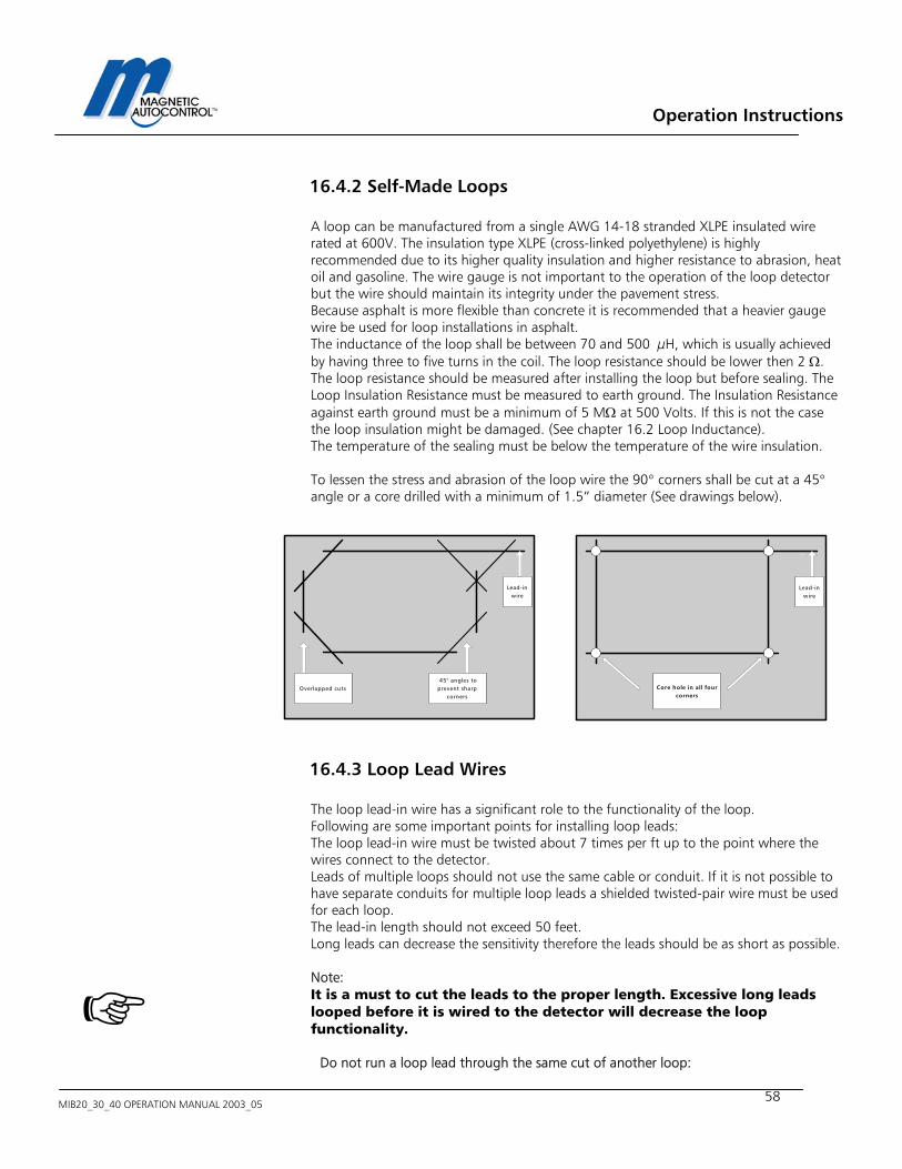
Operation Instructions
MIB20_30_40 OPERATION MANUAL 2003_05
58
16.4.2 Self-Made Loops A loop can be manufactured from a single AWG 14-18 stranded XLPE insulated wire rated at 600V. The insulation type XLPE (cross-linked polyethylene) is highly recommended due to its higher quality insulation and higher resistance to abrasion, heat oil and gasoline. The wire gauge is not important to the operation of the loop detector but the wire should maintain its integrity under the pavement stress. Because asphalt is more flexible than concrete it is recommended that a heavier gauge wire be used for loop installations in asphalt. The inductance of the loop shall be between 70 and 500 µH, which is usually achieved by having three to five turns in the coil. The loop resistance should be lower then 2 Ω. The loop resistance should be measured after installing the loop but before sealing. The Loop Insulation Resistance must be measured to earth ground. The Insulation Resistance against earth ground must be a minimum of 5 MΩ at 500 Volts. If this is not the case the loop insulation might be damaged. (See chapter 16.2 Loop Inductance). The temperature of the sealing must be below the temperature of the wire insulation. To lessen the stress and abrasion of the loop wire the 90° corners shall be cut at a 45° angle or a core drilled with a minimum of 1.5” diameter (See drawings below).
16.4.3 Loop Lead Wires
The loop lead-in wire has a significant role to the functionality of the loop. Following are some important points for installing loop leads: The loop lead-in wire must be twisted about 7 times per ft up to the point where the wires connect to the detector. Leads of multiple loops should not use the same cable or conduit. If it is not possible to have separate conduits for multiple loop leads a shielded twisted-pair wire must be used for each loop. The lead-in length should not exceed 50 feet. Long leads can decrease the sensitivity therefore the leads should be as short as possible. Note: It is a must to cut the leads to the proper length. Excessive long leads looped before it is wired to the detector will decrease the loop functionality.
Do not run a loop lead through the same cut of another loop:
Overlapped cuts 45° angles toprevent sharp
corners
Lead-inwire
Lead-inwire
Core hole in all fourcorners
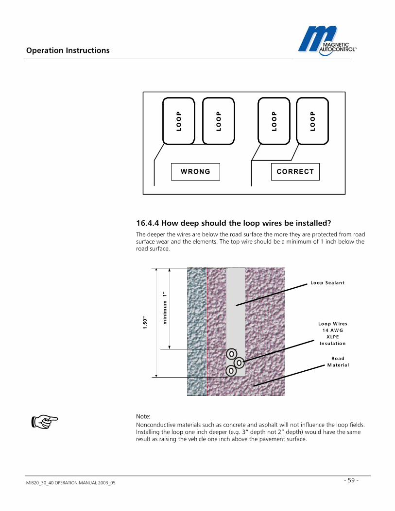
Operation Instructions
MIB20_30_40 OPERATION MANUAL 2003_05 - 59 -
16.4.4 How deep should the loop wires be installed? The deeper the wires are below the road surface the more they are protected from road surface wear and the elements. The top wire should be a minimum of 1 inch below the road surface. Note: Nonconductive materials such as concrete and asphalt will not influence the loop fields. Installing the loop one inch deeper (e.g. 3” depth not 2” depth) would have the same result as raising the vehicle one inch above the pavement surface.
LO
OP
LO
OP
LO
OP
WRONG CORRECTL
OO
P
Loop Sea lant
RoadM ateria l
Loop W ires14 A W G
XLPEInsu lation
1.50
"
min
imum
1"
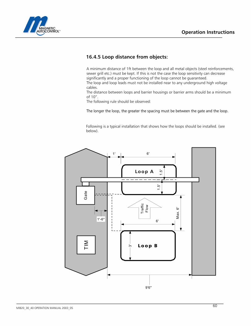
Operation Instructions
MIB20_30_40 OPERATION MANUAL 2003_05
60
16.4.5 Loop distance from objects: A minimum distance of 1ft between the loop and all metal objects (steel reinforcements, sewer grill etc.) must be kept. If this is not the case the loop sensitivity can decrease significantly and a proper functioning of the loop cannot be guaranteed. The loop and loop leads must not be installed near to any underground high voltage cables. The distance between loops and barrier housings or barrier arms should be a minimum of 10”. The following rule should be observed: The longer the loop, the greater the spacing must be between the gate and the loop. Following is a typical installation that shows how the loops should be installed. (see below).
TIM Lo o p B
Loop A
1.5'
1.5'
6'
3'
6'
Max
. 6'
1'
9'6"
Gat
e
Tra
ffic
Flo
w
1'-6"
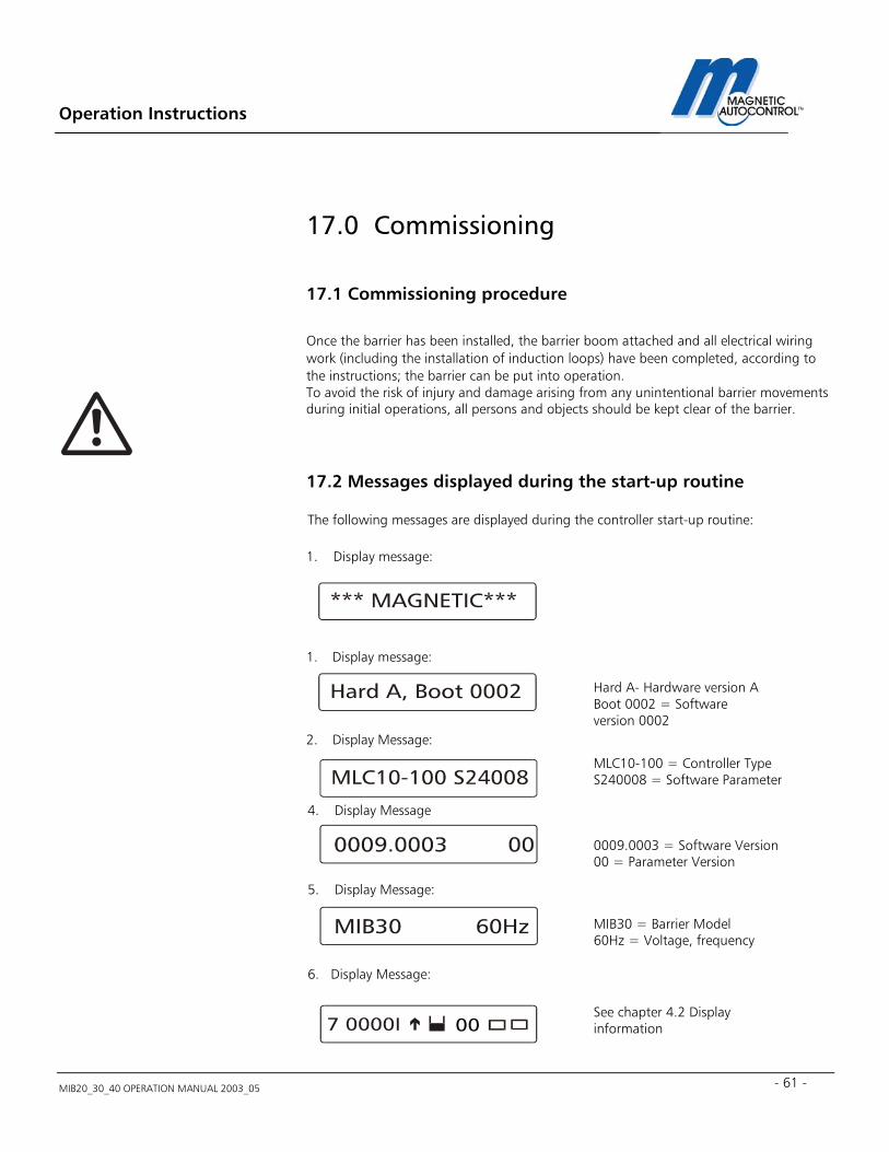
Operation Instructions
MIB20_30_40 OPERATION MANUAL 2003_05 - 61 -
17.0 Commissioning
17.1 Commissioning procedure Once the barrier has been installed, the barrier boom attached and all electrical wiring work (including the installation of induction loops) have been completed, according to the instructions; the barrier can be put into operation. To avoid the risk of injury and damage arising from any unintentional barrier movements during initial operations, all persons and objects should be kept clear of the barrier.
17.2 Messages displayed during the start-up routine The following messages are displayed during the controller start-up routine: 1. Display message:
1. Display message: 2. Display Message:
4. Display Message
5. Display Message:
6. Display Message:
Hard A- Hardware version A Boot 0002 = Software version 0002
MLC10-100 = Controller Type S240008 = Software Parameter
0009.0003 = Software Version 00 = Parameter Version
MIB30 = Barrier Model 60Hz = Voltage, frequency
00
See chapter 4.2 Display information
Operation Instructions
MIB20_30_40 OPERATION MANUAL 2003_05
62
Note: Ex factory the barrier is shipped with the reset function as “SIGNAL RESET” (see chapter 14.5 RESETTING THE BARRIER). After resetting the controller the barrier is now fully functioning. Please use the wiring diagrams displayed in chapter 5.0 PROGRAMMING MODES for Input wiring.
17.3 Standard Configuration: Following are the standard controller configuration ex-factory:
17.3.1 Parking or access control configuration: Program Mode: 7 see chapter 5.1.7 Loop A Sensitivity: 5 see chapter 8.0 and 15.3 Loop B Sensitivity: 5 see chapter 8.0 and 15.3 Loop Mode A: 2 see chapter 9.0 Loop Mode B: 2 presence see chapter 9.0 Safety Angle: 15° see chapter 15.1
17.3.2 Toll road application: Program Mode: 4 see chapter 5.1.7 Hold Open Time: 35sec. see chapter 7.0 Loop A Sensitivity: 5 see chapter 8.0 and 15.3 Loop B Sensitivity: 5 see chapter 8.0 and 15.3 Loop Mode A: 0 see chapter 9.0 Loop Mode B: 0 see chapter 9.0 Safety Angle: 15° see chapter 15.1 Note: If your installation requires different setting please follow the instructions in the corresponding chapters.
Operation Instructions
MIB20_30_40 OPERATION MANUAL 2003_05 - 63 -
18.0 Installation Example:
18.1 Free exit or entry configuration: For a free entry or exit application please follow these steps: 1.0 Program Mode setting: Mode 5, 6, 7 and 8 will work as free exit or entry application, depending on the application, set the mode accordingly. Please read chapter 5.1.5, 5.1.6,5.1.7 and 5.1.8 for details. Typical is Program Mode 5, which will close after the adjustable hold open timer elapses if no vehicle passed through the safety/closing loop. If this installation requires that the gate should stay up if no vehicle passes through the safety/closing loop then choose Program Mode 7. 2.0 Loop Mode A setting: Depending on the installation requirements, set Loop Mode A to meet those specifications. Please read chapter 9.0 for further details. Typical is Loop Mode 2, which issues a potential free maintained contact on relay K1 when a car is on the Loop. 3.0 Loop Mode B setting: Depending on the installation requirements, set Loop Mode B to meet those specifications. Please read chapter 9.3 for further details. For free exit or entry Loop Mode B must be set to “OPENING LOOP”. The output relay is typically set to 2 to receive a potential free maintained output on relay K2 whenever a vehicle is on the loop. Typical is Loop Mode 2, which issues a maintained potential free contact whenever a vehicle is on the loop. 4.0 Hold Open Timer setting: If this installation requires that the gate closes automatically after receiving an opening command without a vehicle passing through the safety closing zone, set Program Mode to 5 or 6 and set the hold-open timer according to your requirements. Please read chapter 7.0 for further details Typical hold open timer setting is 35sec. Note: After all settings are done, return the rotary switch to position 0 for normal operation. The barrier is now in full operation mode.
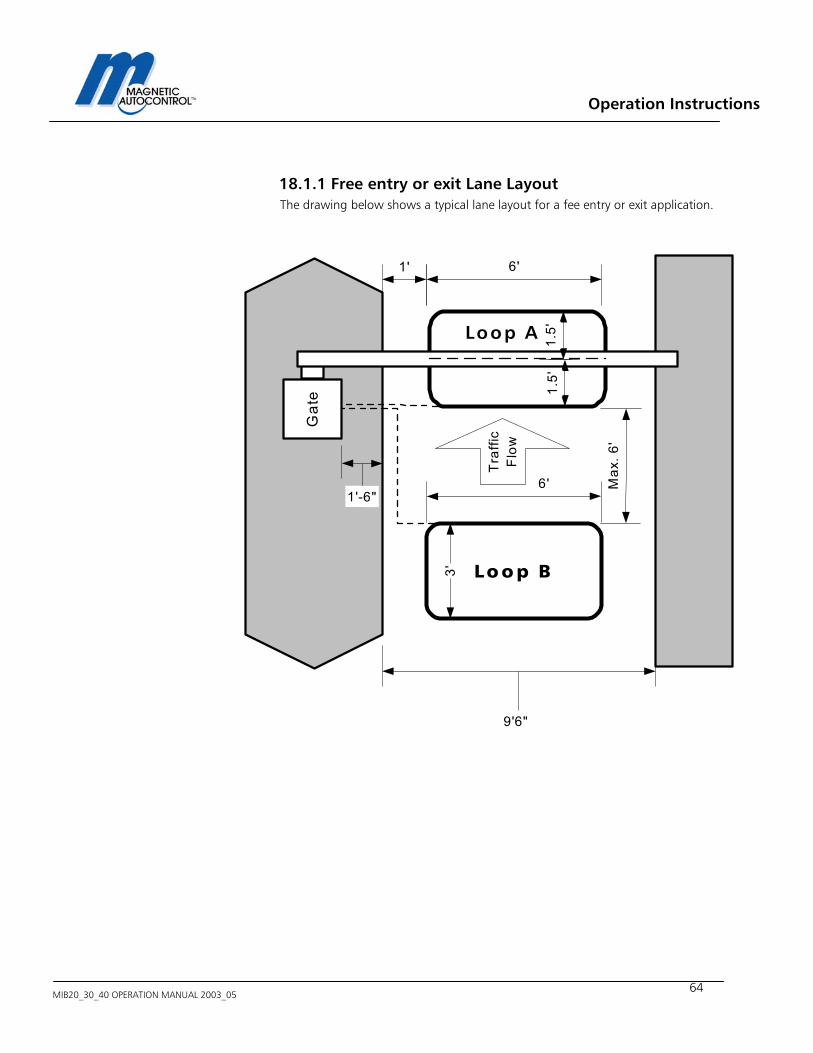
Operation Instructions
MIB20_30_40 OPERATION MANUAL 2003_05
64
18.1.1 Free entry or exit Lane Layout The drawing below shows a typical lane layout for a fee entry or exit application.
Lo o p B
Loop A 1.5'
1.5'
6'
3'
6' Max
. 6'
1'
9'6"
Gat
e
Tra
ffic
Flo
w1'-6"
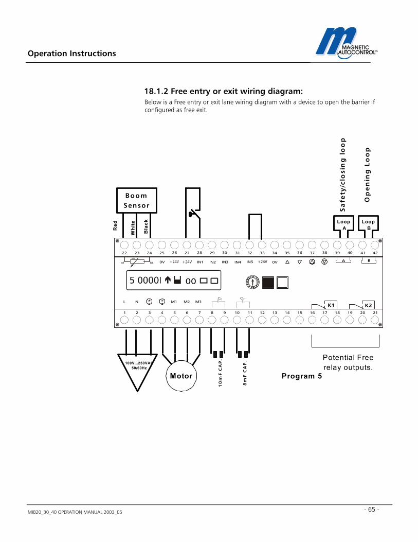
Operation Instructions
MIB20_30_40 OPERATION MANUAL 2003_05 - 65 -
18.1.2 Free entry or exit wiring diagram: Below is a Free entry or exit lane wiring diagram with a device to open the barrier if configured as free exit.
BoomSensor
Motor Program 5
Loop A
M1
IN1 IN2 IN3 IN4 IN5
L NC C
0V 0V
M2 M3
272625242322 37363534333231302928 4241403938
A B
654321 16151413121110987 2120191817
K1 K2
bkrd
wh
00
10
mF
CA
P.
8m
F C
AP
.
Loop BR
ed
Whi
te
Bla
ck
100V...250VAC50/60Hz
Potential Freerelay outputs.
Sa
fety
/clo
sin
g l
oo
p
Op
en
ing
Lo
op
Operation Instructions
MIB20_30_40 OPERATION MANUAL 2003_05
66
18.2 Entry or exit with access control: For a access controlled entry or exit , do the following: 1.0 Program Mode setting: Mode 5, 6, 7 and 8 will work for this application, depending on the application, set the mode accordingly. Please read chapter 5.1.5, 5.1.6,5.1.7 and 5.1.8 for details. Typical is Program Mode 7, which will remain open if no vehicle passed through the safety/closing zone. If this installation requires that the gate should automatically close if no vehicle passes through the safety/closing loop, choose Program Mode 5. 2.0 Loop Mode A setting: Depending on the installation requirements set Loop Mode A to meet those specifications. Please read chapter 9.0 for further details. Typical is Loop Mode 2, which issued a potential free maintained contact on relay K1 when a car is on the Loop. This can be used to reset the access control equipment. 3.0 Loop Mode B setting: In an access control application Loop B is used as presence (arming) loop. Please read chapter 9.3 for further details. To arm the access control equipment when a vehicle is present set the Loop Mode to 2 and “PRESENCE LOOP”. This will issue a potential free maintained contact at Relay K2 whenever a vehicle is on the loop. Typical is Loop Mode 2, which issues a maintained potential free contact at relay K2 whenever a vehicle is on the loop. 4.0 Hold Open Timer setting: If this installation requires that the gate closes automatically after receiving an opening command without a vehicle passing through the safety closing zone, set Program Mode to 5 or 6 and set the hold-open timer according to your requirements. Please read chapter 7.0 for further details. Typical hold open timer setting is 35sec.
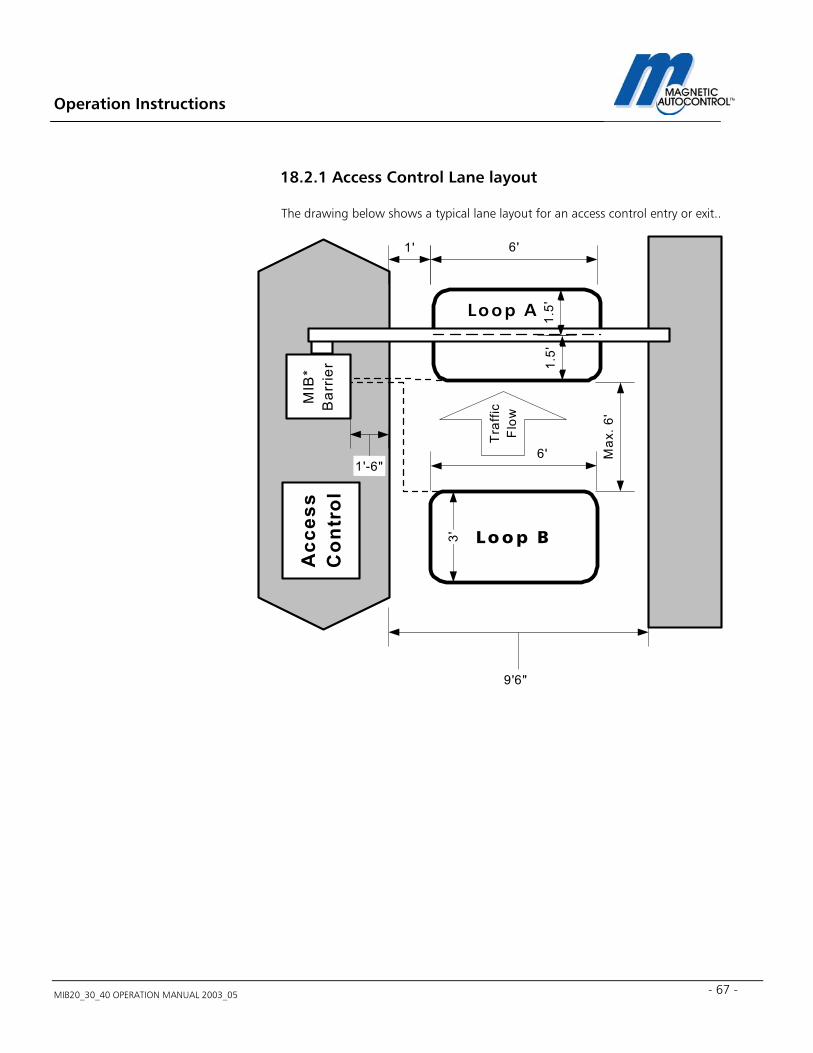
Operation Instructions
MIB20_30_40 OPERATION MANUAL 2003_05 - 67 -
18.2.1 Access Control Lane layout The drawing below shows a typical lane layout for an access control entry or exit..
Acc
ess
Con
trol
Lo o p B
Loop A 1.5'
1.5'
6'
3'6' M
ax. 6
'
1'
9'6"
MIB
*B
arrie
r
Tra
ffic
Flo
w
1'-6"
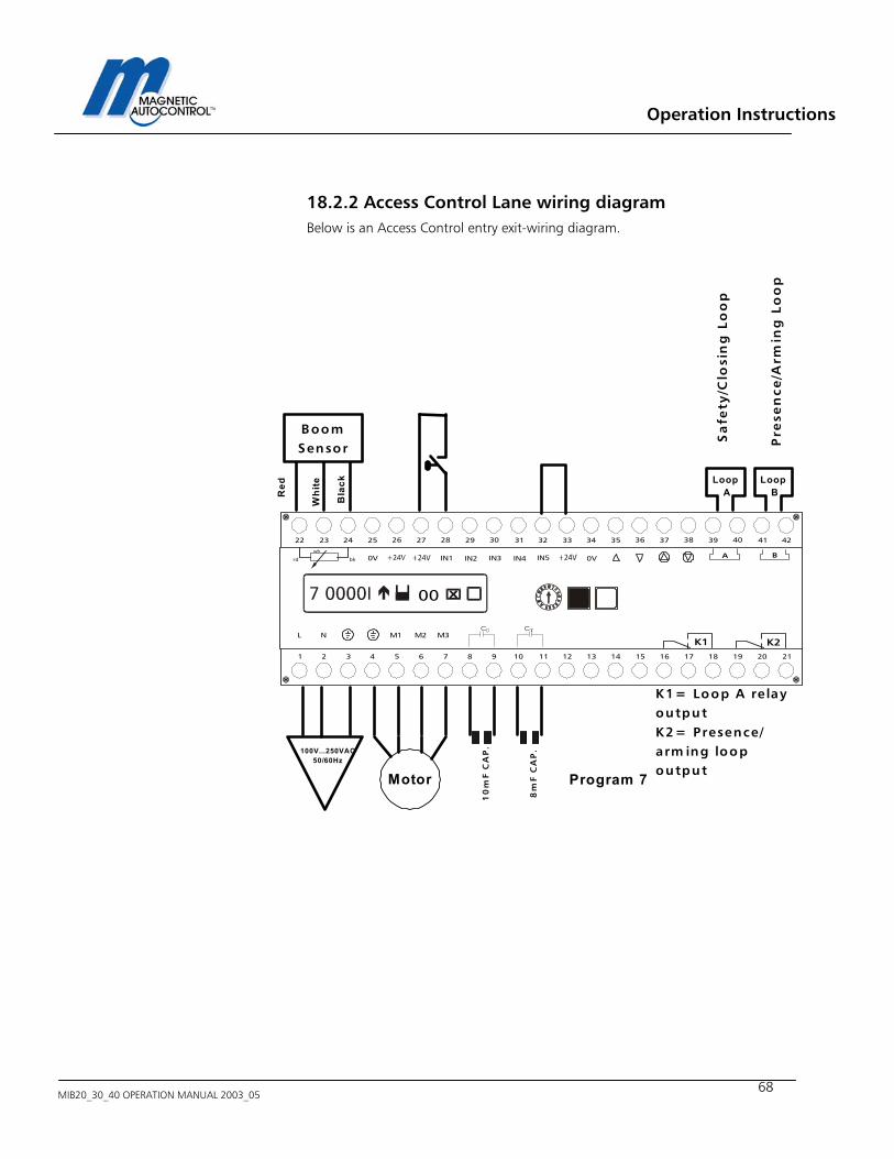
Operation Instructions
MIB20_30_40 OPERATION MANUAL 2003_05
68
18.2.2 Access Control Lane wiring diagram Below is an Access Control entry exit-wiring diagram.
BoomSensor
Motor Program 7
Loop A
M1
IN1 IN2 IN3 IN4 IN5
L NC C
0V 0V
M2 M3
272625242322 37363534333231302928 4241403938
A B
654321 16151413121110987 2120191817
K1 K2
bkrd
wh
00
10
mF
CA
P.
8m
F C
AP
.
Loop BR
ed
Whi
te
Bla
ck
100V...250VAC50/60Hz
Sa
fety
/Clo
sin
g L
oo
p
Pre
sen
ce/A
rmin
g L
oo
p
K1= Loop A re layoutputK2= Presence/arm ing loopoutput
Operation Instructions
MIB20_30_40 OPERATION MANUAL 2003_05 - 69 -
18.3 Access Control one direction free in/out other direction
1.0 Program Mode setting: Mode 6 and 8 are recommended for this application. See chapter 5.1.6, and 5.1.8 for details. If the installation requires a presence loop to arm the access control equipment an additional loop detector is required. Typical is Program Mode 6, which will close after the adjustable hold open timer elapses if no vehicle passed through the safety/closing loop. If this installation requires that the gate should stay up if no vehicle passes through the safety/closing loop choose Program Mode 8. 2.0 Loop Mode A setting: Loop A can only be used for the safety/closing function of the barrier. Depending on the installation requirements, set Loop Mode A to meet those specifications. Please read chapter 9.0 for further details. Typical is Loop Mode 2, which issues a potential free maintained contact on relay K1 when a car is on the Loop. 3.0 Loop Mode B setting: Depending on the installations requirements, set Loop Mode B to meet those specifications. Please read chapter 9.3 for further details. For free exit or entry Loop Mode B must be set to “OPENING LOOP”. The output relay is typically set to 2 to receive a potential free maintained output on relay K2 whenever a vehicle is on the loop. Typical is Loop Mode 2, which issues a maintained potential free contact whenever a vehicle is on the loop. 4.0 Hold Open Timer setting: If this installation requires that the gate closes automatically after receiving an opening command without a vehicle passing through the safety closing zone, set Program Mode to 6 and set the hold-open timer according to your requirements. Please read chapter 7.0 for further details Typical hold open timer setting is 35sec. Note: After all settings are done return the rotary switch to position 0 for normal operation. The barrier is now in full operation mode. If the installation requires a presence loop to arm the access control equipment an additional loop detector is required. No external wiring of the opening loop is required. The MLC controller handles the opening of the barrier internally.
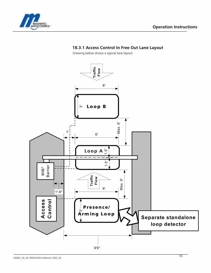
Operation Instructions
MIB20_30_40 OPERATION MANUAL 2003_05
70
18.3.1 Access Control In Free Out Lane Layout Drawing below shows a typical lane layout:
Acc
ess
Con
trol
Presence /A rm ing Lo o p
Loop A 1.5'
1.5'
6'
3'
6' Max
. 6 '
1'
9'6"
MIB
*B
arrie
r
Traf
ficFl
ow
1'-6"
Loop B
Max
. 6'
6'3'
Traf
ficFl
ow
Separate standaloneloop detector
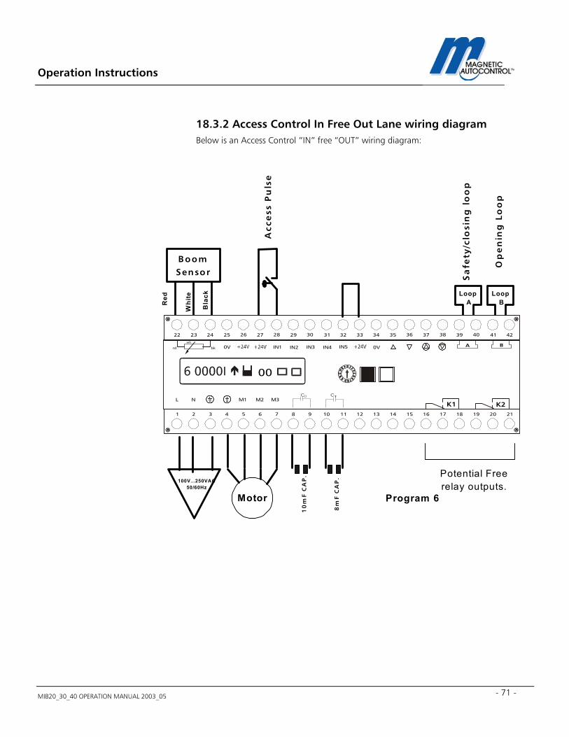
Operation Instructions
MIB20_30_40 OPERATION MANUAL 2003_05 - 71 -
18.3.2 Access Control In Free Out Lane wiring diagram Below is an Access Control “IN” free “OUT” wiring diagram:
BoomSensor
Motor Program 6
Loop A
M1
IN1 IN2 IN3 IN4 IN5
L NC C
0V 0V
M2 M3
272625242322 37363534333231302928 4241403938
A B
654321 16151413121110987 2120191817
K1 K2
bkrd
wh
00
10
mF
CA
P.
8m
F C
AP
.
Loop BR
ed
Whi
te
Bla
ck
100V...250VAC50/60Hz
Potential Freerelay outputs.
Sa
fety
/clo
sin
g l
oo
p
Op
en
ing
Lo
op
Acc
ess
Pu
lse
Operation Instructions
MIB20_30_40 OPERATION MANUAL 2003_05
72
18.4 Master Slave configuration In a master slave configuration, the master barrier controls the slave barrier. All access control wiring must go to the master barrier. An additional relay (see chapter 18.4.2) is required to achieve this function. The Master can be set in Mode 5 through 8 and the Slave barrier must be set to Mode 1. 1.0 Program Mode setting: Master Barrier: Mode 5, 6, 7 and 8 will work for this application. Depending on the application, set the mode accordingly. Please read chapter 5.1.5, 5.1.6,5.1.7 and 5.1.8 for details. Typical is Program Mode 7, which will remain open if no vehicle passed through the safety/closing zone. If this installation requires that the gate should automatically close if no vehicle passes through the safety/closing loop choose Program Mode 5 or 8. Slave Barrier: The slave barrier will only function in Program Mode 1. 2.0 Loop Mode A setting: Master Barrier: Depending on the installation requirements set Loop Mode A to meet those specifications. Please read chapter 9.0 for further details. Typical is Loop Mode 2, which issues a potential free maintained contact on relay K1 when a car is on the Loop. This can be used to reset the access control equipment. Slave Barrier: The Loop Mode A for the slave barrier should be 0 (= disabled). In wide lanes that require more then one loop, connect them in series to the Master MLC controller. 3.0 Loop Mode B setting: Master Barrier: In an access control application Loop B is used as a presence (arming) loop. Please read chapter 9.3 for further details. If no presence (arming) loop is required set Loop Mode B to 0. To arm the access control equipment when a vehicle is present you must set the Loop Mode to “2” and “PRESENCE LOOP”. This will issue a potential free maintained contact on relay K2 whenever a vehicle is on the loop. In a free entry or exit application, Loop B must be set to “OPENING LOOP” and the Mode depends on the application. Typical is Loop Mode 2, which issues a maintained potential free contact at relay K2 whenever a vehicle is on the loop. Slave Barrier: Loop B must be set to 0 (= disabled).
Operation Instructions
MIB20_30_40 OPERATION MANUAL 2003_05 - 73 -
4.0 Hold Open Timer setting: Master Barrier: If this installation requires that the gate closes automatically after receiving an opening command without a vehicle passing through the safety closing zone, set Program Mode to 5 or 6 and set the hold-open timer according your requirements. Please read chapter 7.0 for further details. Typical hold open timer setting is 35sec. Slave Barrier: The Slave barrier is operated in Program Mode 1, which doesn’t support this feature, but the slave barrier will operate simultaneously with the Master barrier.
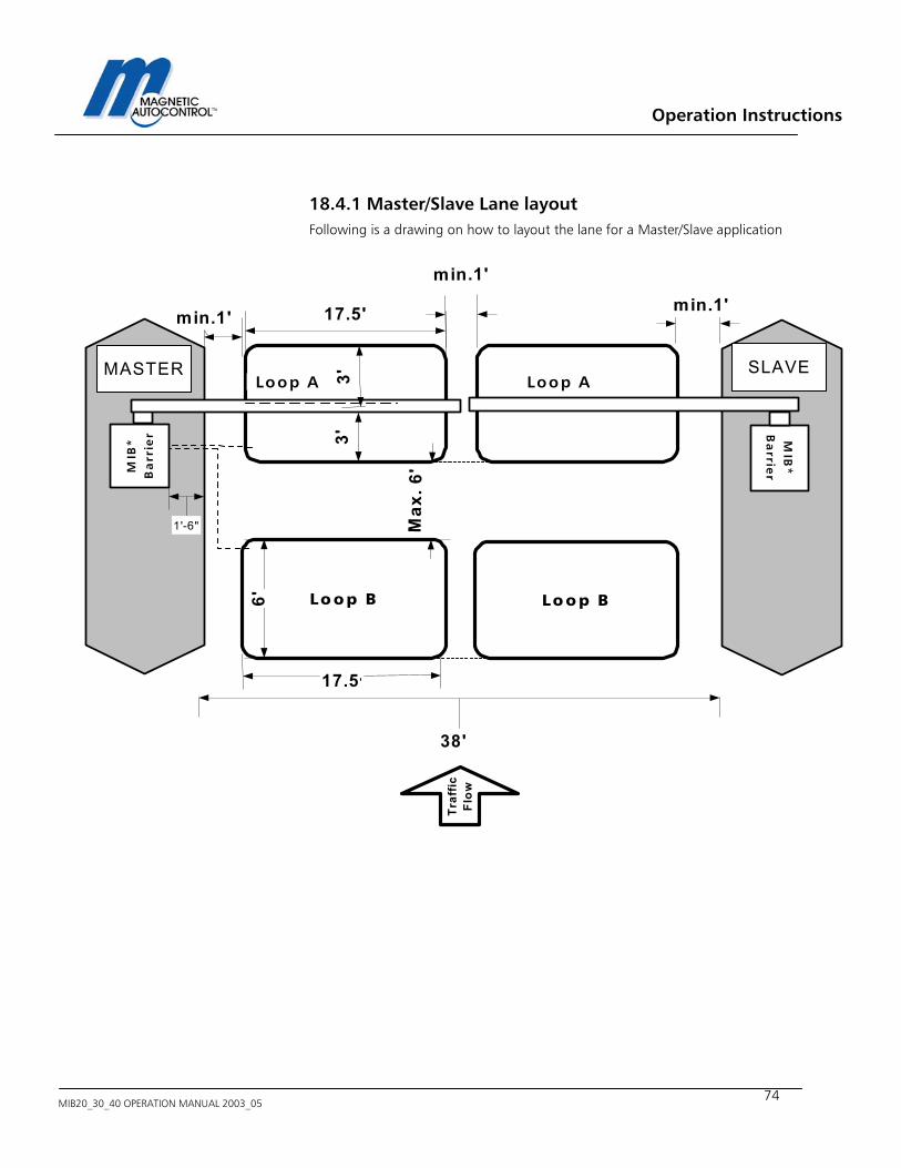
Operation Instructions
MIB20_30_40 OPERATION MANUAL 2003_05
74
18.4.1 Master/Slave Lane layout Following is a drawing on how to layout the lane for a Master/Slave application
Lo op B
Loop A 3'3'
17.5'
6'
17.5 '
Max
. 6'
min.1'
38'
MIB
*B
arr
ier
Traf
ficFl
ow
1'-6"
MIB
*B
arrie
r
MASTER SLAVE
Lo o p B
Loop A
min.1'
min.1'
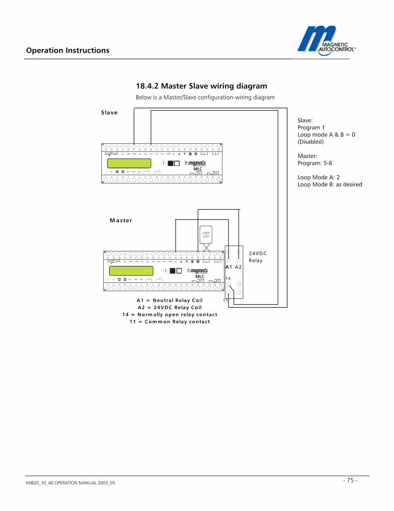
Operation Instructions
MIB20_30_40 OPERATION MANUAL 2003_05 - 75 -
18.4.2 Master Slave wiring diagram Below is a Master/Slave configuration-wiring diagram
M 1
IN 1 IN 2 IN 3 IN 4 IN 5
L NC C
0V 0V
M 2 M 3
272625242322 37363534333231302928 4241403938
A B
654321 16151413121110987 2120191817
K 1 K2
AB
CD
EF 0 1 2
34
56
789
bkrd
w h
M 1
IN 1 IN 2 IN 3 IN 4 IN 5
L NC C
0V 0V
M 2 M 3
272625242322 37363534333231302928 4241403938
A B
654321 16151413121110987 2120191817
K1 K 2
AB
CD
EF 0 1 2
34
56
789
bkrd
w h
M aster
S lave
A2A1A1
11
14
24VD CRelay
A 1 = N eutral Re lay Co ilA 2 = 24VD C Relay Co il
14 = N orm ally open re lay contact11 = Com m on Relay contact
Operation Instructions
MIB20_30_40 OPERATION MANUAL 2003_05
76
18.5 Toll Road application: In most Toll-road applications, a lane controller controls the gate. Therefore the gate controller must respond to all inputs without being in an automatic mode. This is achieved by using Program Mode 4. See chapter 5.1.4 for details. 1.0 Program Mode setting: Mode 4 is recommended for this application. See chapter 5.1.4 for details. Mode 4 will open the barrier when an input on IN1 is made and will close when an input on IN3 was made. The inputs shall be pulses of minimum 300msec.. 2.0 Loop Mode A setting: Loop A is set to Loop Mode 0 ex factory. Loop Mode 0 disables the loop detector and enables a potential free contact on relay K1 when the barrier is in the full up position. See chapter 9.2 for details. 3.0 Loop Mode B setting: Loop B is set to Loop Mode 0 ex factory. Loop Mode 0 disables the loop detector and enables a potential free contact on relay K2 when the barrier is in the full down position. See chapter 9.3 for details. 4.0 Hold Open Timer setting: The Hold open timer has no function in Mode 4. Note: After all settings are done return the rotary switch to position 0 for normal operation. The barrier is now in full operation mode. If the installation requires a input override switch connect a normally open contact to input IN2 of the controller. This input overrides all existing inputs.
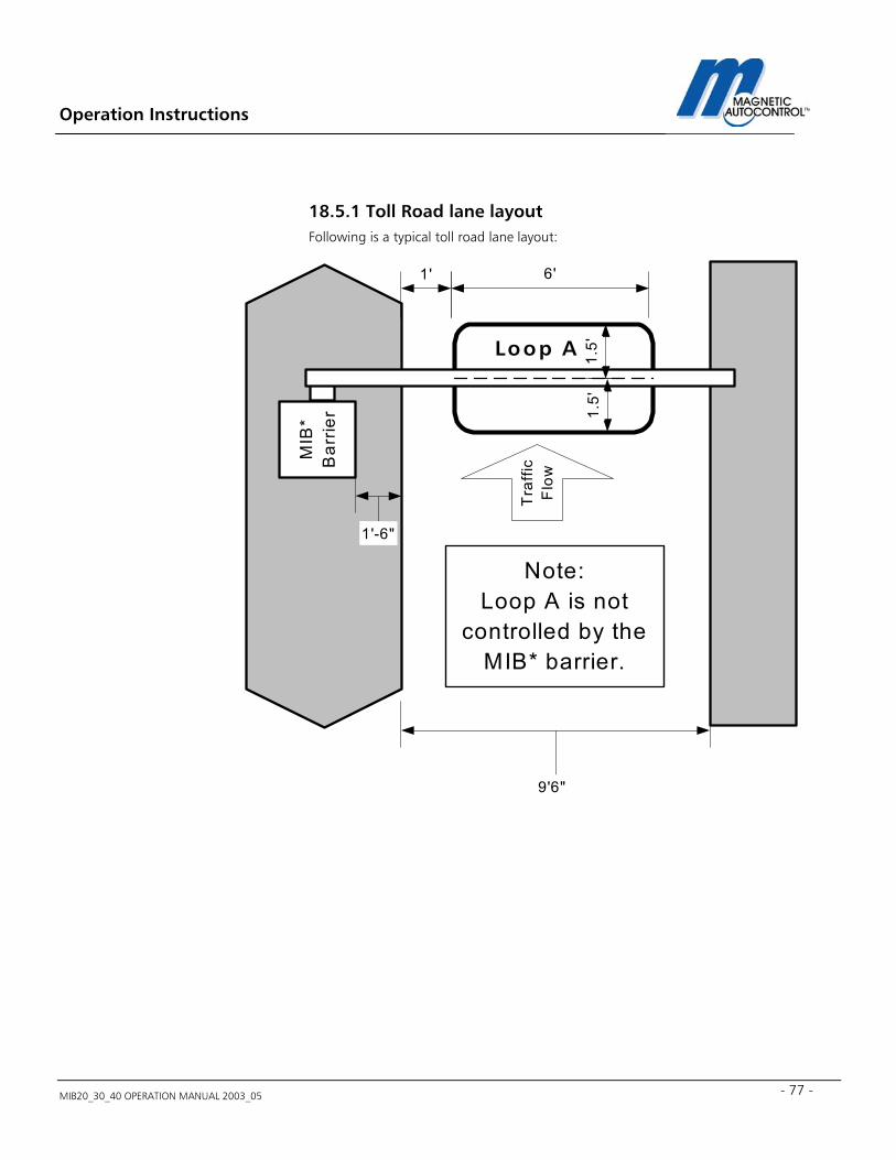
Operation Instructions
MIB20_30_40 OPERATION MANUAL 2003_05 - 77 -
18.5.1 Toll Road lane layout Following is a typical toll road lane layout:
Loop A 1.5'
1.5'
6'1'
9'6"
MIB
*B
arrie
r
Tra
ffic
Flo
w1'-6"
Note:Loop A is not
controlled by theMIB* barrier.
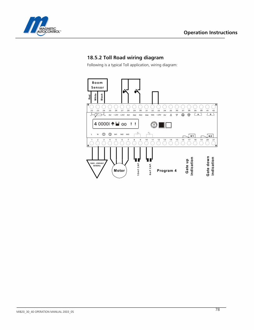
Operation Instructions
MIB20_30_40 OPERATION MANUAL 2003_05
78
18.5.2 Toll Road wiring diagram Following is a typical Toll application, wiring diagram:
BoomSensor
Red
Whi
te
Bla
ck
Motor
100V...250VAC50/60Hz
Program 4
M1
IN1 IN2 IN3 IN4 IN5
L NC C
0V 0V
M2 M3
272625242322 37363534333231302928 4241403938
A B
654321 16151413121110987 2120191817
K1 K2
bkrd
wh
00 !!
10
mF
CA
P.
8m
F C
AP
.
Gat
e up
indi
catio
n
Gat
e do
wn
indi
catio
n

Operation Instructions
MIB20_30_40 OPERATION MANUAL 2003_05 - 79 -
19.0 MIB* barrier with boom Lock mechanism The MIB* barriers can be operated with the boom locking mechanism. Please see Magnetic Info sheet MM5141 for details. The Info sheet is attached to this manual if a MIB* barrier with locking mechanism was purchased. Following is a wiring diagram showing the connection of the MLC controller and the MMV1C-100 boom-locking controller:
BoomSensor
Red
Whi
te
Bla
ck
M1
IN1 IN2 IN3 IN4 IN5
L NC C
0V 0V
M2 M3
272625242322 37363534333231302928 4241403938
A B
654321 16151413121110987 2120191817
K1 K2
bkrd
wh
00
Motor
100V...250VAC50/60Hz
1 2 3 4 5
6 7 8 9 10
MMV
Lock
ing
me
cha
nis
m2
4V
DC
ma
x.1
75
mA
NE
UT
RA
L
LIN
E1
15
VA
C
GR
OU
ND
Loop A
Loop B
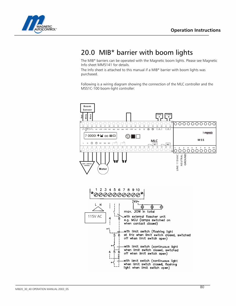
Operation Instructions
MIB20_30_40 OPERATION MANUAL 2003_05
80
20.0 MIB* barrier with boom lights The MIB* barriers can be operated with the Magnetic boom lights. Please see Magnetic Info sheet MM5141 for details. The Info sheet is attached to this manual if a MIB* barrier with boom lights was purchased. Following is a wiring diagram showing the connection of the MLC controller and the MSS1C-100 boom-light controller:
BoomSensor
Red
Whi
te
Bla
ck
M1
IN1 IN2 IN3 IN4 IN5
L NC C
0V 0V
M2 M3
272625242322 37363534333231302928 4241403938
A B
654321 16151413121110987 2120191817
K1 K2
bkrd
wh
00
Motor
100V...250VAC50/60Hz
M SS
NE
UT
RA
L
LIN
E1
15
VA
C
GRO
UN
D
Loop A
Loop B
1 2 3 4 5 6 7 8 9 10
115V AC
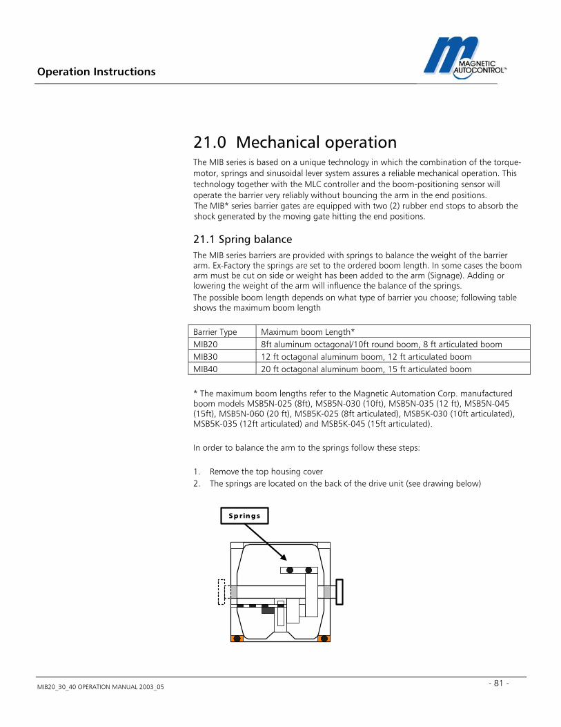
Operation Instructions
MIB20_30_40 OPERATION MANUAL 2003_05 - 81 -
21.0 Mechanical operation The MIB series is based on a unique technology in which the combination of the torque- motor, springs and sinusoidal lever system assures a reliable mechanical operation. This technology together with the MLC controller and the boom-positioning sensor will operate the barrier very reliably without bouncing the arm in the end positions. The MIB* series barrier gates are equipped with two (2) rubber end stops to absorb the shock generated by the moving gate hitting the end positions.
21.1 Spring balance The MIB series barriers are provided with springs to balance the weight of the barrier arm. Ex-Factory the springs are set to the ordered boom length. In some cases the boom arm must be cut on side or weight has been added to the arm (Signage). Adding or lowering the weight of the arm will influence the balance of the springs. The possible boom length depends on what type of barrier you choose; following table shows the maximum boom length Barrier Type Maximum boom Length* MIB20 8ft aluminum octagonal/10ft round boom, 8 ft articulated boom MIB30 12 ft octagonal aluminum boom, 12 ft articulated boom MIB40 20 ft octagonal aluminum boom, 15 ft articulated boom * The maximum boom lengths refer to the Magnetic Automation Corp. manufactured boom models MSB5N-025 (8ft), MSB5N-030 (10ft), MSB5N-035 (12 ft), MSB5N-045 (15ft), MSB5N-060 (20 ft), MSB5K-025 (8ft articulated), MSB5K-030 (10ft articulated), MSB5K-035 (12ft articulated) and MSB5K-045 (15ft articulated).
In order to balance the arm to the springs follow these steps: 1. Remove the top housing cover 2. The springs are located on the back of the drive unit (see drawing below)
Sp rings

Operation Instructions
MIB20_30_40 OPERATION MANUAL 2003_05
82
3. Each boom length requires different spring tension and therefore different quantities of springs (see table below)
Boom Length MIB20 MIB30 MIB40 MSB5N -025 8FT ALUMINUM OCTAGONAL 2 2 MSB5N -030 10FT ALUMINUM OCTAGONAL N/A 3 MSB5N -035 12FT ALUMINUM OCTAGONAL N/A 4 2 (STRONG SPRINGS, YELLOW MARK)* MSB5N -045 15FT ALUMINUM OCTAGONAL N/A N/A 4 (STRONG SPRINGS, YELLOW MARK)* MSB5N-060 20FT ALUMINUM OCTAGONAL N/A N/A 6 (STRONG SPRINGS, YELLOW MARK)* MSB4B-030 10FT ROUND ALUMINUM BOOM 3 3 N/A
* The MIB40 uses a springs that have a higher tension then the MIB20&30’s. The MIB40 springs are marked with yellow paint on each of the ends. The above table does not ably to articulated barrier arms (Part# MSB5K-025/030/035/045). All Magnetic Automation Corp. articulated barrier arms are custom made to specifications provided by the client. The differences in the lane clearance height influence the weight of the barrier arm and therefore each articulated arm must be adjusted to the individual barrier.
4. In order to balance the springs you have to move the barrier arm to a 45° angle. The
gate arm is balanced when it stays at this position without any electrical power applied to the gate.
5. If the arm moves down, the springs are too weak; if it moves up the springs are too tight.
6. To adjust the springs to the correct tension, remove the plastic clips that hold the adjustment screws in place. Turn the adjustment screws to raise or lower the springs (raise= higher tension, low= lower tension) until the arm is balanced.
7. After balancing the arm replace the plastic spring clips. 8. Replace the housing lid and turn the power on. 9. Now the controller brake needs to be set to the new settings. Follow instructions in
chapter 22.1 to re-adjust the gate arm brake settings.
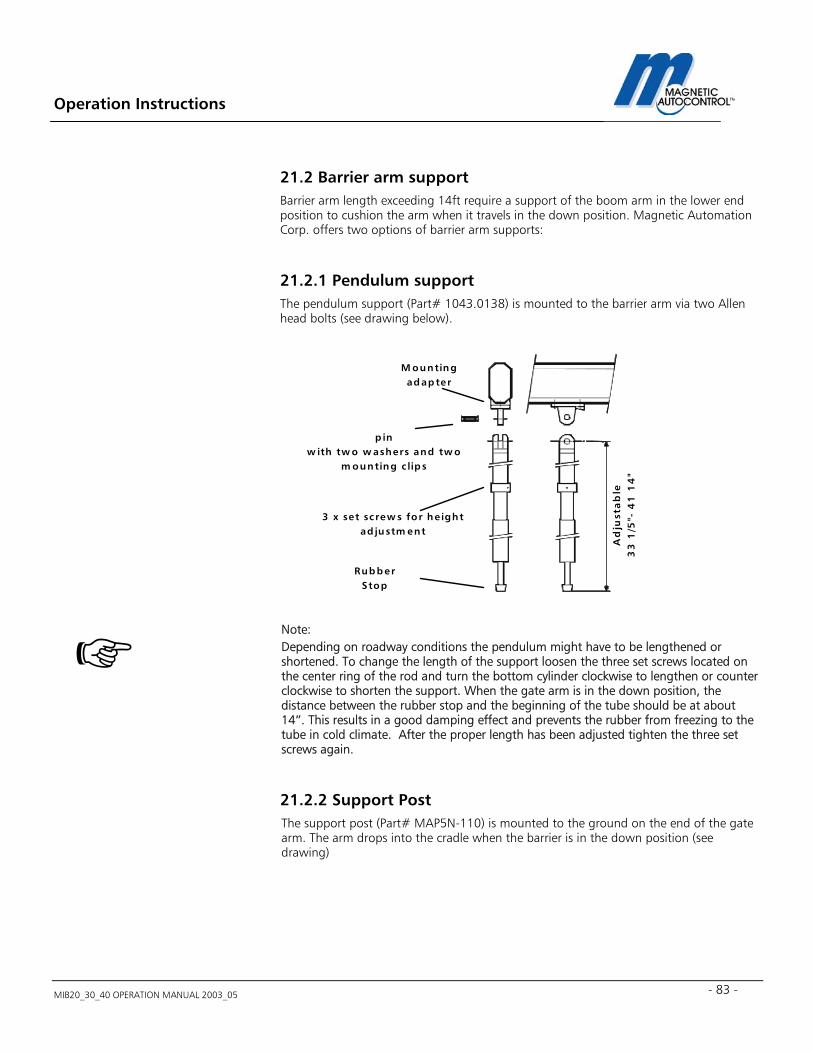
Operation Instructions
MIB20_30_40 OPERATION MANUAL 2003_05 - 83 -
21.2 Barrier arm support Barrier arm length exceeding 14ft require a support of the boom arm in the lower end position to cushion the arm when it travels in the down position. Magnetic Automation Corp. offers two options of barrier arm supports:
21.2.1 Pendulum support The pendulum support (Part# 1043.0138) is mounted to the barrier arm via two Allen head bolts (see drawing below).
Note: Depending on roadway conditions the pendulum might have to be lengthened or shortened. To change the length of the support loosen the three set screws located on the center ring of the rod and turn the bottom cylinder clockwise to lengthen or counter clockwise to shorten the support. When the gate arm is in the down position, the distance between the rubber stop and the beginning of the tube should be at about 14”. This results in a good damping effect and prevents the rubber from freezing to the tube in cold climate. After the proper length has been adjusted tighten the three set screws again.
21.2.2 Support Post The support post (Part# MAP5N-110) is mounted to the ground on the end of the gate arm. The arm drops into the cradle when the barrier is in the down position (see drawing)
M ountingadapter
p inw ith tw o w ashers and tw o
m ounting c lips
3 x set screw s for he ightad justm ent
Ad
just
ab
le3
3 1
/5"-
41
14
"
RubberStop
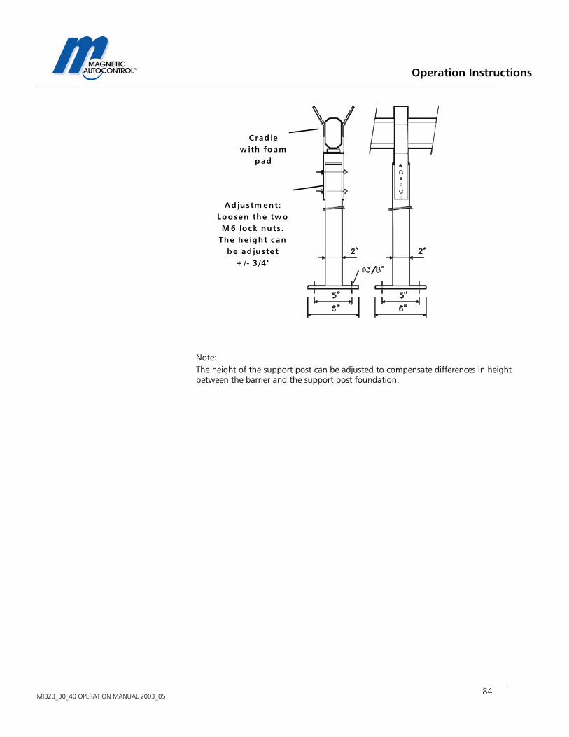
Operation Instructions
MIB20_30_40 OPERATION MANUAL 2003_05
84
Note: The height of the support post can be adjusted to compensate differences in height between the barrier and the support post foundation.
Crad lew ith foam
pad
Ad justm ent:Loosen the tw oM 6 lock nuts.
The he ight canbe ad justet
+ /- 3 /4 "
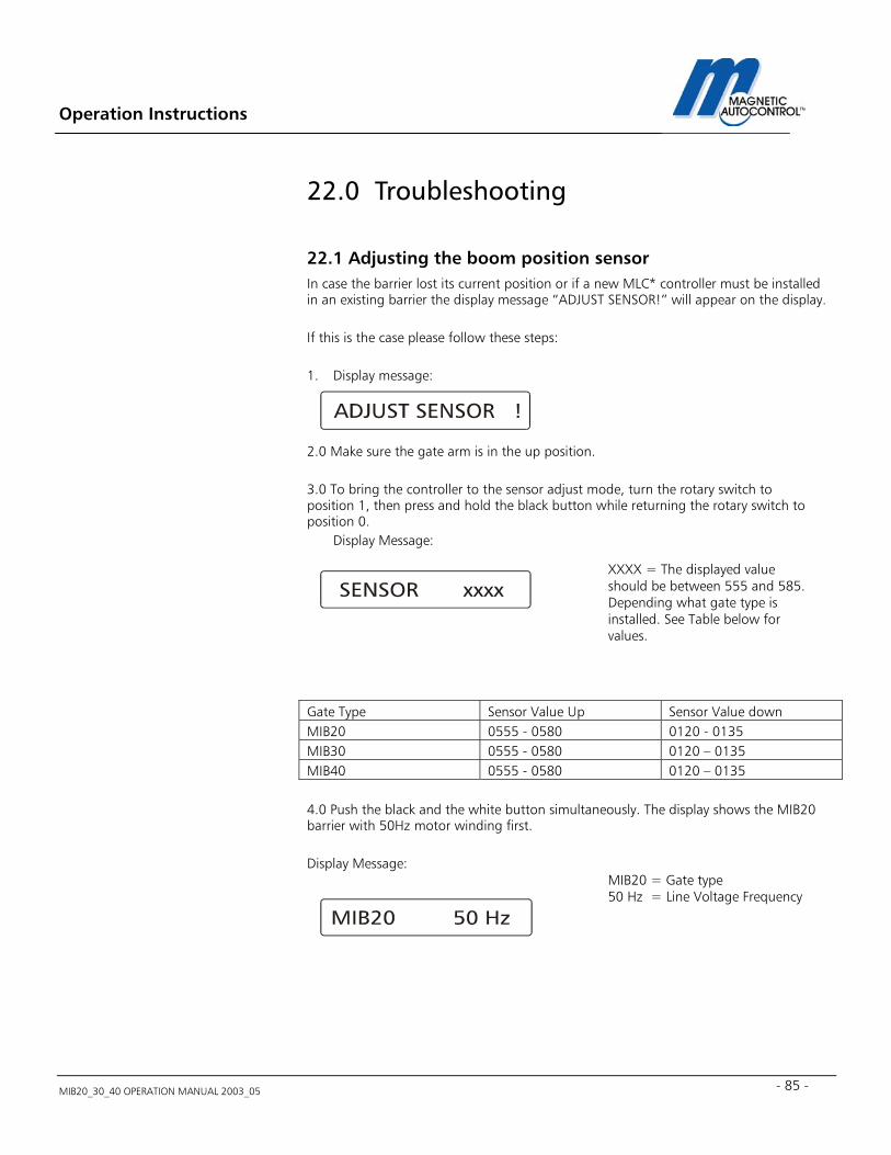
Operation Instructions
MIB20_30_40 OPERATION MANUAL 2003_05 - 85 -
22.0 Troubleshooting
22.1 Adjusting the boom position sensor In case the barrier lost its current position or if a new MLC* controller must be installed in an existing barrier the display message “ADJUST SENSOR!” will appear on the display. If this is the case please follow these steps: 1. Display message: 2.0 Make sure the gate arm is in the up position. 3.0 To bring the controller to the sensor adjust mode, turn the rotary switch to position 1, then press and hold the black button while returning the rotary switch to position 0.
Display Message:
Gate Type Sensor Value Up Sensor Value down MIB20 0555 - 0580 0120 - 0135 MIB30 0555 - 0580 0120 – 0135 MIB40 0555 - 0580 0120 – 0135 4.0 Push the black and the white button simultaneously. The display shows the MIB20 barrier with 50Hz motor winding first. Display Message:
XXXX = The displayed value should be between 555 and 585. Depending what gate type is installed. See Table below for values.
MIB20 = Gate type 50 Hz = Line Voltage Frequency
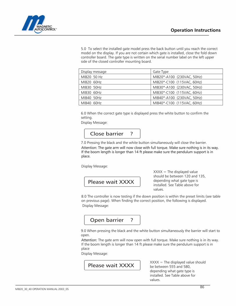
Operation Instructions
MIB20_30_40 OPERATION MANUAL 2003_05
86
5.0 To select the installed gate model press the back button until you reach the correct model on the display. If you are not certain which gate is installed, close the fold down controller board. The gate type is written on the serial number label on the left upper side of the closed controller mounting board. Display message Gate Type MIB20 50 Hz MIB20*-A100 (230VAC, 50Hz) MIB20 60Hz MIB20*-C100 (115VAC, 60Hz) MIB30 50Hz MIB30*-A100 (230VAC, 50Hz) MIB30 60Hz MIB30*-C100 (115VAC, 60Hz) MIB40 50Hz MIB40*-A100 (230VAC, 50Hz) MIB40 60Hz MIB40*-C100 (115VAC, 60Hz) 6.0 When the correct gate type is displayed press the white button to confirm the setting. Display Message: 7.0 Pressing the black and the white button simultaneously will close the barrier. Attention: The gate arm will now close with full torque. Make sure nothing is in its way. If the boom length is longer than 14 ft please make sure the pendulum support is in place. Display Message: 8.0 The controller is now testing if the down position is within the preset limits (see table on previous page). When finding the correct position, the following is displayed. Display Message: 9.0 When pressing the black and the white button simultaneously the barrier will start to open. Attention: The gate arm will now open with full torque. Make sure nothing is in its way. If the boom length is longer than 14 ft please make sure the pendulum support is in place Display Message:
XXXX = The displayed value should be between 120 and 135, depending what gate type is installed. See Table above for values.
XXXX = The displayed value should be between 555 and 580, depending what gate type is installed. See Table above for values.
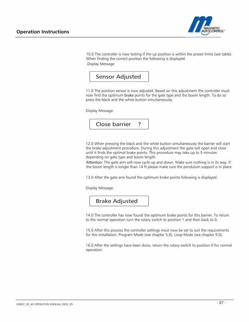
Operation Instructions
MIB20_30_40 OPERATION MANUAL 2003_05 - 87 -
10.0 The controller is now testing if the up position is within the preset limits (see table). When finding the correct position the following is displayed. Display Message:
11.0 The position sensor is now adjusted. Based on this adjustment the controller must now find the optimum brake points for the gate type and the boom length. To do so press the black and the white button simultaneously. Display Message: 12.0 When pressing the black and the white button simultaneously the barrier will start the brake adjustment procedure. During this adjustment the gate will open and close until it finds the optimal brake points. This procedure may take up to 5 minutes depending on gate type and boom length. Attention: The gate arm will now cycle up and down. Make sure nothing is in its way. If the boom length is longer than 14 ft please make sure the pendulum support is in place. 13.0 After the gate arm found the optimum brake points following is displayed. Display Message: 14.0 The controller has now found the optimum brake points for this barrier. To return to the normal operation turn the rotary switch to position 1 and then back to 0. 15.0 After this process the controller settings must now be set to suit the requirements for this installation: Program Mode (see chapter 5.0), Loop Mode (see chapter 9.0). 16.0 After the settings have been done, return the rotary switch to position 0 for normal operation.
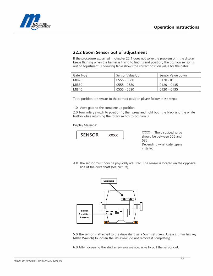
Operation Instructions
MIB20_30_40 OPERATION MANUAL 2003_05
88
22.2 Boom Sensor out of adjustment If the procedure explained in chapter 22.1 does not solve the problem or if the display keeps flashing when the barrier is trying to find its end position, the position sensor is out of adjustment. Following table shows the correct position value for the gates Gate Type Sensor Value Up Sensor Value down MIB20 0555 - 0580 0120 - 0135 MIB30 0555 - 0580 0120 – 0135 MIB40 0555 - 0580 0120 – 0135 To re-position the sensor to the correct position please follow these steps: 1.0 Move gate to the complete up position 2.0 Turn rotary switch to position 1, then press and hold both the black and the white button while returning the rotary switch to position 0. Display Message: 4.0 The sensor must now be physically adjusted. The sensor is located on the opposite
side of the drive shaft (see picture). 5.0 The sensor is attached to the drive shaft via a 5mm set screw. Use a 2.5mm hex key (Allen Wrench) to loosen the set-screw (do not remove it completely). 6.0 After loosening the stud screw you are now able to pull the sensor out.
XXXX = The displayed value should be between 555 and 585. Depending what gate type is installed.
Bo o mPo sitio nSenso r
Springs
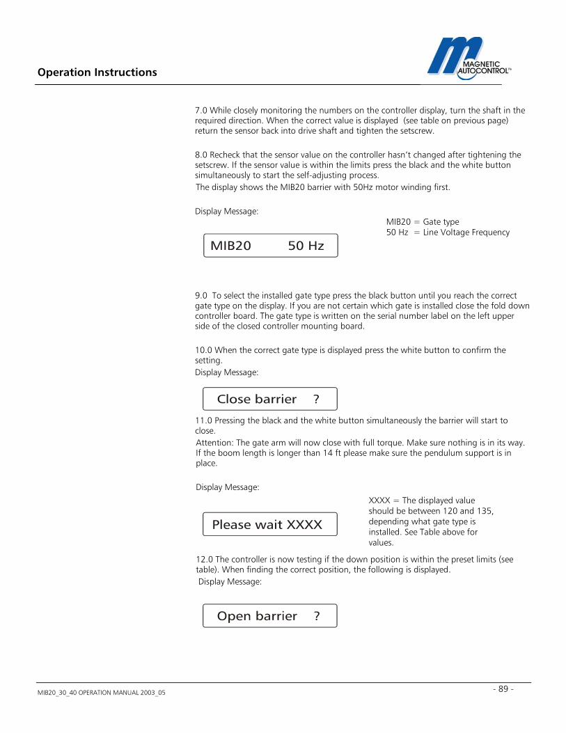
Operation Instructions
MIB20_30_40 OPERATION MANUAL 2003_05 - 89 -
7.0 While closely monitoring the numbers on the controller display, turn the shaft in the required direction. When the correct value is displayed (see table on previous page) return the sensor back into drive shaft and tighten the setscrew. 8.0 Recheck that the sensor value on the controller hasn’t changed after tightening the setscrew. If the sensor value is within the limits press the black and the white button simultaneously to start the self-adjusting process. The display shows the MIB20 barrier with 50Hz motor winding first. Display Message: 9.0 To select the installed gate type press the black button until you reach the correct gate type on the display. If you are not certain which gate is installed close the fold down controller board. The gate type is written on the serial number label on the left upper side of the closed controller mounting board. 10.0 When the correct gate type is displayed press the white button to confirm the setting. Display Message: 11.0 Pressing the black and the white button simultaneously the barrier will start to close. Attention: The gate arm will now close with full torque. Make sure nothing is in its way. If the boom length is longer than 14 ft please make sure the pendulum support is in place. Display Message: 12.0 The controller is now testing if the down position is within the preset limits (see table). When finding the correct position, the following is displayed. Display Message:
MIB20 = Gate type 50 Hz = Line Voltage Frequency
XXXX = The displayed value should be between 120 and 135, depending what gate type is installed. See Table above for values.
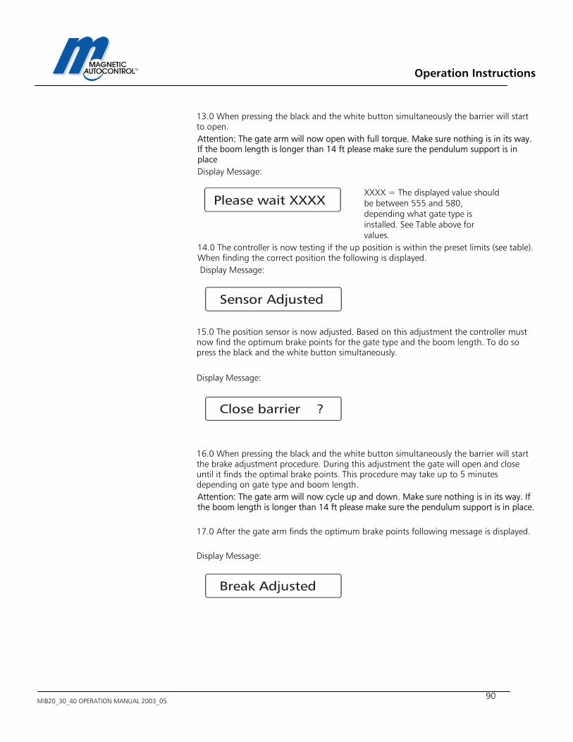
Operation Instructions
MIB20_30_40 OPERATION MANUAL 2003_05
90
13.0 When pressing the black and the white button simultaneously the barrier will start to open. Attention: The gate arm will now open with full torque. Make sure nothing is in its way. If the boom length is longer than 14 ft please make sure the pendulum support is in place Display Message:
14.0 The controller is now testing if the up position is within the preset limits (see table). When finding the correct position the following is displayed. Display Message:
15.0 The position sensor is now adjusted. Based on this adjustment the controller must now find the optimum brake points for the gate type and the boom length. To do so press the black and the white button simultaneously. Display Message: 16.0 When pressing the black and the white button simultaneously the barrier will start the brake adjustment procedure. During this adjustment the gate will open and close until it finds the optimal brake points. This procedure may take up to 5 minutes depending on gate type and boom length. Attention: The gate arm will now cycle up and down. Make sure nothing is in its way. If the boom length is longer than 14 ft please make sure the pendulum support is in place. 17.0 After the gate arm finds the optimum brake points following message is displayed. Display Message:
XXXX = The displayed value should be between 555 and 580, depending what gate type is installed. See Table above for values.
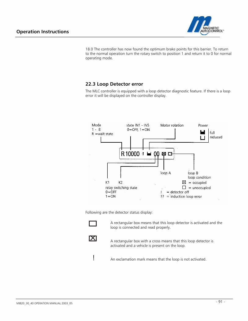
Operation Instructions
MIB20_30_40 OPERATION MANUAL 2003_05 - 91 -
18.0 The controller has now found the optimum brake points for this barrier. To return to the normal operation turn the rotary switch to position 1 and return it to 0 for normal operating mode.
22.3 Loop Detector error The MLC controller is equipped with a loop detector diagnostic feature. If there is a loop error it will be displayed on the controller display. Following are the detector status display:
A rectangular box means that this loop detector is activated and the loop is connected and read properly.
A rectangular box with a cross means that this loop detector is activated and a vehicle is present on the loop.
! An exclamation mark means that the loop is not activated.
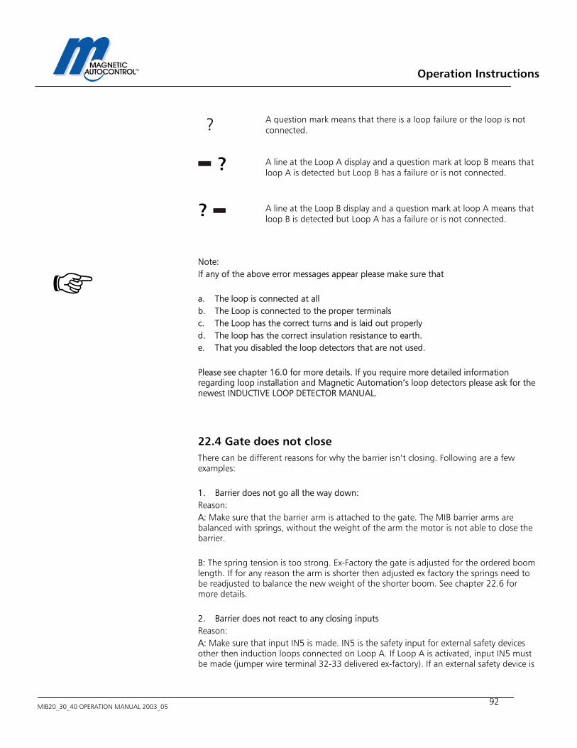
Operation Instructions
MIB20_30_40 OPERATION MANUAL 2003_05
92
Note: If any of the above error messages appear please make sure that a. The loop is connected at all b. The Loop is connected to the proper terminals c. The Loop has the correct turns and is laid out properly d. The loop has the correct insulation resistance to earth. e. That you disabled the loop detectors that are not used. Please see chapter 16.0 for more details. If you require more detailed information regarding loop installation and Magnetic Automation’s loop detectors please ask for the newest INDUCTIVE LOOP DETECTOR MANUAL.
22.4 Gate does not close There can be different reasons for why the barrier isn’t closing. Following are a few examples: 1. Barrier does not go all the way down: Reason: A: Make sure that the barrier arm is attached to the gate. The MIB barrier arms are balanced with springs, without the weight of the arm the motor is not able to close the barrier. B: The spring tension is too strong. Ex-Factory the gate is adjusted for the ordered boom length. If for any reason the arm is shorter then adjusted ex factory the springs need to be readjusted to balance the new weight of the shorter boom. See chapter 22.6 for more details. 2. Barrier does not react to any closing inputs Reason: A: Make sure that input IN5 is made. IN5 is the safety input for external safety devices other then induction loops connected on Loop A. If Loop A is activated, input IN5 must be made (jumper wire terminal 32-33 delivered ex-factory). If an external safety device is
? A question mark means that there is a loop failure or the loop is not connected.
? A line at the Loop A display and a question mark at loop B means that loop A is detected but Loop B has a failure or is not connected.
? A line at the Loop B display and a question mark at loop A means that loop B is detected but Loop A has a failure or is not connected.

Operation Instructions
MIB20_30_40 OPERATION MANUAL 2003_05 - 93 -
used (for example: Photo Beam) the normally closed contact of this device must be connected to this terminal. If Input IN5 is not made the gate will not close. B: Make sure that safety device, externally connected on IN5 (if used) or the internal safety loop A is not triggered. The barrier won’t close if the safety device is activated. C: If the gate should close by passing through the safety device please check if the safety device is actually being triggered when a vehicle drives through the safety zone. If Loop A is used for safety/closing check if a cross appears in the square on the Loop A status display when the vehicle is on the loop. If an external safety/closing device is used make sure the status display of IN5 displays “0” when the vehicle is on the safety zone and returns to “I” when the vehicle has left. The gate should then close. D: If using the safety/closing loop/device to close the gate, make sure the Program mode is set to 5,6,7 or 8 (see chapter 5.0 for more details). C: If you are using inputs to close the barrier make sure you connected it to the correct terminals in respect to the program modes (see chapter 5.0 for more details). Note: In any case; if the barrier does not open or close try the provided gate UP/NORMAL/DOWN switch first to determine if the problem comes from the gate or the peripheral equipment. 22.5 Gate does not open There can be several reasons for why the barrier isn’t opening. Following are a few examples: A: The barrier arm is too heavy. The spring tension is too weak. Ex-Factory the gate is adjusted for the ordered boom length. If for any reason the arm is longer or additional weight was added to it (for example: Stop signs) the springs have to be readjusted to balance the boom arm. The motor is not strong enough to lift the arm if the springs are not balanced with the arm. See chapter 22.6 for more details. B: Make sure the barrier open contact is connected to the correct terminal. See chapter 5.0 for details. C: Make sure that IN3 is not made. This contact has higher priority then IN1. If using IN1 to open the gate IN3 must be off. Note: In any case, if the barrier does not open or close try the provided gate UP/NORMAL/DOWN switch first to determine if the problem comes from the gate or the peripheral equipment.
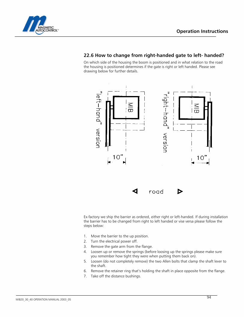
Operation Instructions
MIB20_30_40 OPERATION MANUAL 2003_05
94
22.6 How to change from right-handed gate to left- handed? On which side of the housing the boom is positioned and in what relation to the road the housing is positioned determines if the gate is right or left handed. Please see drawing below for further details. Ex-factory we ship the barrier as ordered, either right or left-handed. If during installation the barrier has to be changed from right to left handed or vise versa please follow the steps below: 1. Move the barrier to the up position. 2. Turn the electrical power off. 3. Remove the gate arm from the flange. 4. Loosen up or remove the springs (before loosing up the springs please make sure
you remember how tight they were when putting them back on). 5. Loosen (do not completely remove) the two Allen bolts that clamp the shaft lever to
the shaft. 6. Remove the retainer ring that’s holding the shaft in place opposite from the flange. 7. Take off the distance bushings.
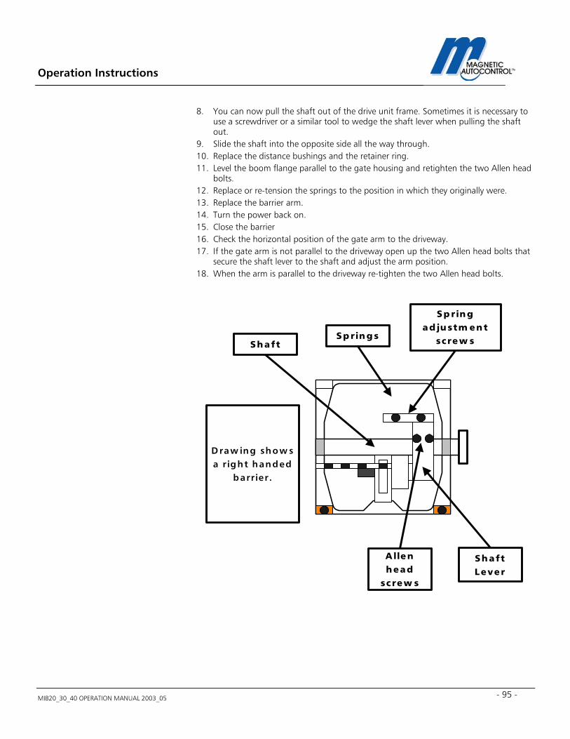
Operation Instructions
MIB20_30_40 OPERATION MANUAL 2003_05 - 95 -
8. You can now pull the shaft out of the drive unit frame. Sometimes it is necessary to use a screwdriver or a similar tool to wedge the shaft lever when pulling the shaft out.
9. Slide the shaft into the opposite side all the way through. 10. Replace the distance bushings and the retainer ring. 11. Level the boom flange parallel to the gate housing and retighten the two Allen head
bolts. 12. Replace or re-tension the springs to the position in which they originally were. 13. Replace the barrier arm. 14. Turn the power back on. 15. Close the barrier 16. Check the horizontal position of the gate arm to the driveway. 17. If the gate arm is not parallel to the driveway open up the two Allen head bolts that
secure the shaft lever to the shaft and adjust the arm position. 18. When the arm is parallel to the driveway re-tighten the two Allen head bolts.
Springs
Springad justm ent
screw sShaft
ShaftLever
A llenhead
screw s
D raw ing show sa right handed
barrier.

Operation Instructions
MIB20_30_40 OPERATION MANUAL 2003_05
96
23.0 Technical Data
23.1 MAGSTOP Barriers MIB20 MIB30 MIB40 Max. Boom length 8FT octagonal/10ft
round 12FT octagonal 20 FT octagonal
Opening/closing time 0, 9 sec 1,4 sec 4,0 sec Power consumption 240 W 120 W 120 W
Housing Zinc-plated sheet steel color powder coated
Zinc-plated sheet steel color powder coated
Zinc-plated sheet steel color powder coated
Housing dimensions (W x D x H)
14” x 14”x 42” 14” x 14”x 42” 14” x 14”x 42”
Foundation base frame Stainless steel Stainless steel Stainless steel
Weight (without arm) 145 lbs. 145 lbs. 145 lbs.
Operating temp. Range (Ambient)
-22°F TO +140°F -22°F TO +140°F -22°F TO +140°F
Drive Unit Torque motor Torque motor Torque motor
23.2 Controller Unit MLC10 MLC11* Voltage (+/- 10%) Volt 100-240 100-240 Frequency Hertz 50 - 60 50 - 60 Max. power consumption
Watt 20 20
Fuse F4AH F4AH
Control Voltage 24 V DC / max. 300 mA
24 V DC / max. 300 mA”
No. of inputs 5 5 No of zero-potential changeover relays
max.250V AC/3A 2 2 2
No. of open collector outputs
max.50mA/24V DC 2 2
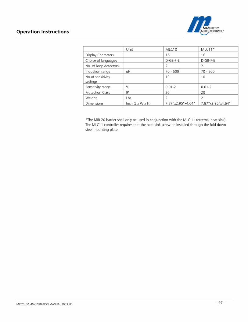
Operation Instructions
MIB20_30_40 OPERATION MANUAL 2003_05 - 97 -
Unit MLC10 MLC11* Display Characters 16 16
Choice of languages D-GB-F-E D-GB-F-E
No. of loop detectors 2 2
Induction range µH 70 - 500 70 - 500
No of sensitivity settings
10 10
Sensitivity range % 0.01-2 0.01-2
Protection Class IP 20 20
Weight Lbs 2 2
Dimensions Inch (L x W x H) 7.87”x2.95”x4.64” 7.87”x2.95”x4.64”
*The MIB 20 barrier shall only be used in conjunction with the MLC 11 (external heat sink). The MLC11 controller requires that the heat sink screw be installed through the fold down steel mounting plate.
Operation Instructions
MIB20_30_40 OPERATION MANUAL 2003_05
98
24. Maintenance The MIB20/30/40 series barrier gates are designed for a long lifetime with only a minimum of maintenance required. To guarantee the greatest available equipment uptime and maximize the lifetime of the MIB20/30/40 series barriers please follow the prescribed maintenance schedules. Use the Maintenance Service Record, located on page 98, to keep track of your maintenance and upkeep activities on the MIB series barrier models.
24.1 Changing the Rubber End Stop The MIB* series barrier gates are equipped with two (2) rubber end stops to absorb the shock generated by the moving gate hitting the end positions. Those rubber end stops need to be replaced once per year or after one million cycles whatever comes first.
24.2 Checking the Exterior of Cabinet Inspect the housing for vehicular damage every six months.
24.3 Check the barrier arm and the attachment kit Inspect the barrier arm for physical damage and check if the barrier arm attachment kit is used properly and all parts are in place and tight. Perform this inspection every six months.
24.4 Checking the Loop Detectors and Loop Wires Check the frequencies of the loops every six months. The loop wires should be replaced approximately every four years or as needed. Check the loop sealant every year for cracks or peeling. Replace if needed.
24.5 Check safety signage Inspect for proper attachment of all safety related signage such as Gate Cabinet and barrier arm safety sticker.

Operation Instructions
MIB20_30_40 OPERATION MANUAL 2003_05 - 99 -
This Page was intentionally left blank.
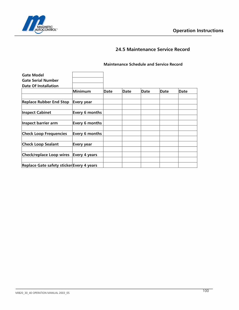
Operation Instructions
MIB20_30_40 OPERATION MANUAL 2003_05
100
24.5 Maintenance Service Record
Maintenance Schedule and Service Record Gate Model Gate Serial Number Date Of Installation Minimum Date Date Date Date Date Replace Rubber End Stop Every year Inspect Cabinet Every 6 months Inspect barrier arm Every 6 months Check Loop Frequencies Every 6 months Check Loop Sealant Every year Check/replace Loop wires Every 4 years Replace Gate safety sticker Every 4 years
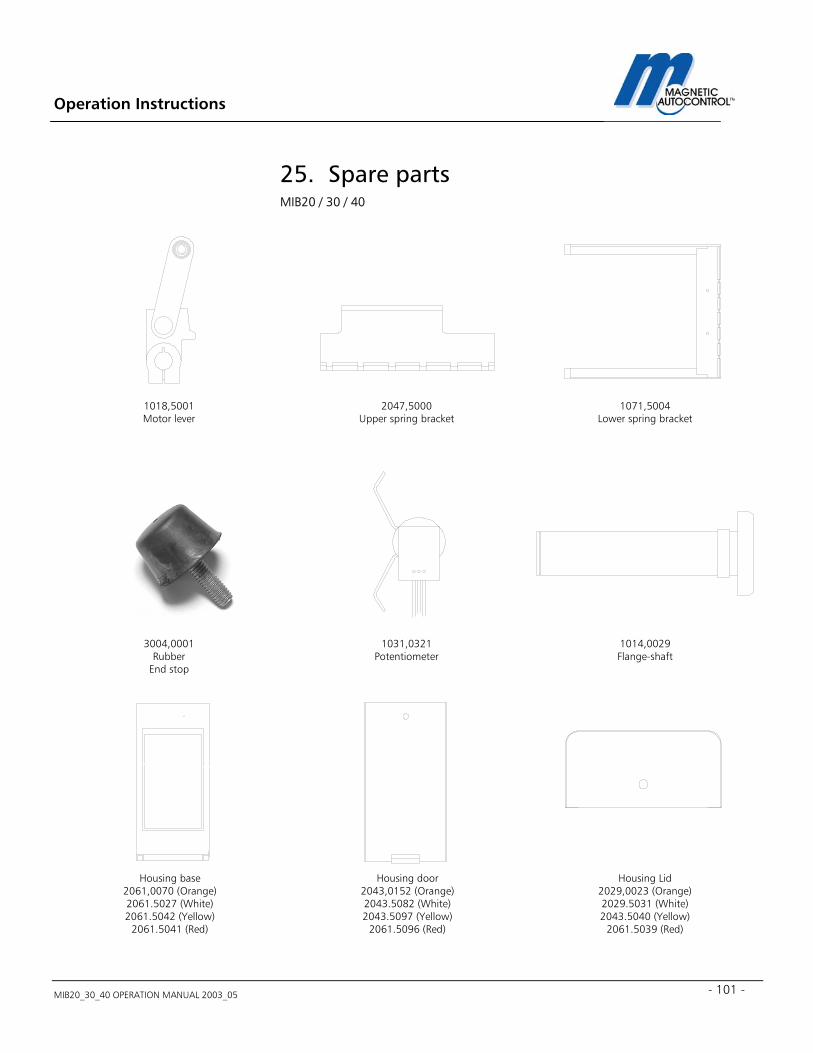
Operation Instructions
MIB20_30_40 OPERATION MANUAL 2003_05 - 101 -
25. Spare parts MIB20 / 30 / 40
1018,5001 Motor lever
2047,5000 Upper spring bracket
1071,5004 Lower spring bracket
3004,0001 Rubber
End stop
1031,0321 Potentiometer
1014,0029 Flange-shaft
Housing base 2061,0070 (Orange) 2061.5027 (White) 2061.5042 (Yellow)
2061.5041 (Red)
Housing door 2043,0152 (Orange) 2043.5082 (White) 2043.5097 (Yellow)
2061.5096 (Red)
Housing Lid 2029,0023 (Orange) 2029.5031 (White) 2043.5040 (Yellow)
2061.5039 (Red)
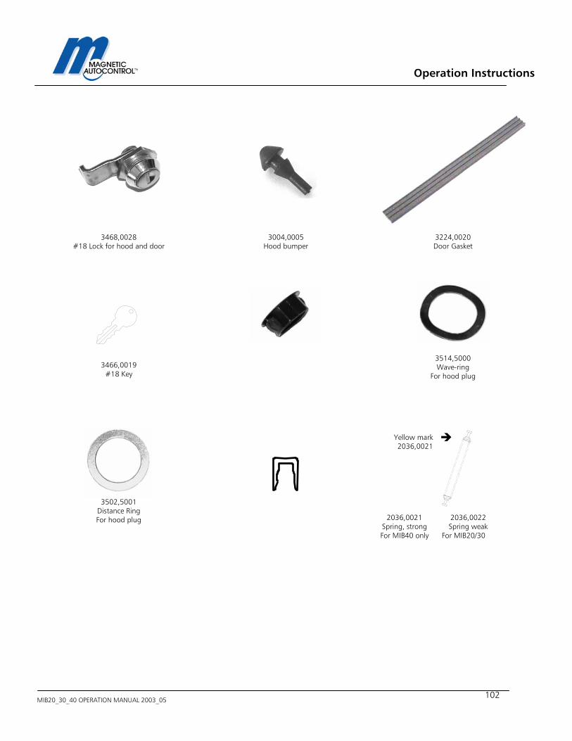
Operation Instructions
MIB20_30_40 OPERATION MANUAL 2003_05
102
3468,0028
#18 Lock for hood and door 3004,0005
Hood bumper 3224,0020 Door Gasket
3466,0019
#18 Key
3514,5000 Wave-ring
For hood plug
3502,5001
Distance Ring For hood plug
Yellow mark 2036,0021
2036,0021
Spring, strong For MIB40 only
2036,0022 Spring weak
For MIB20/30
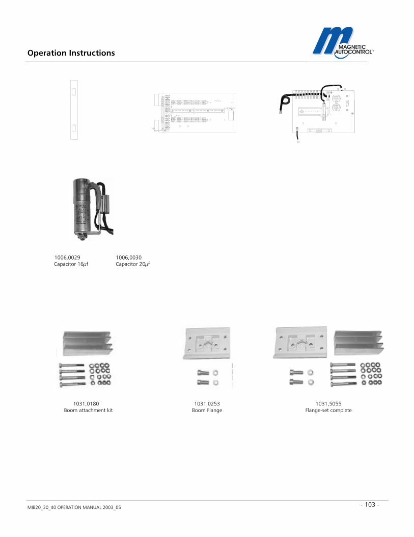
Operation Instructions
MIB20_30_40 OPERATION MANUAL 2003_05 - 103 -
1006,0029 Capacitor 16µf
1006,0030 Capacitor 20µf
1031,0180 Boom attachment kit
1031,0253 Boom Flange
1031,5055 Flange-set complete
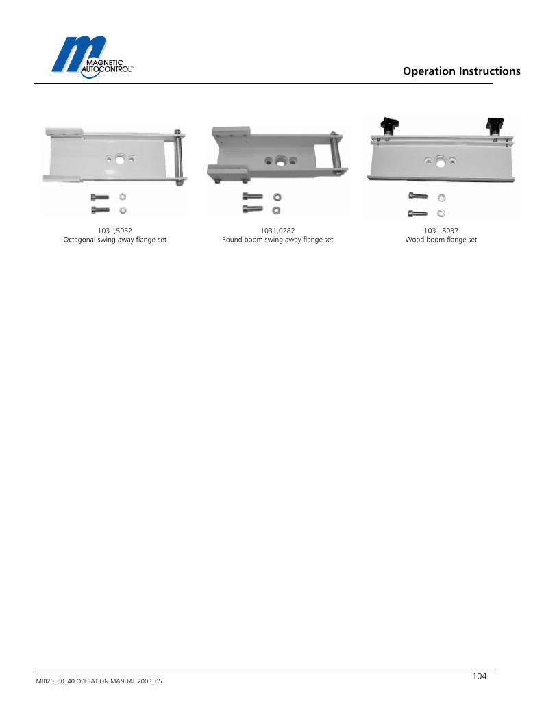
Operation Instructions
MIB20_30_40 OPERATION MANUAL 2003_05
104
1031,5052
Octagonal swing away flange-set
1031,0282 Round boom swing away flange set
1031,5037 Wood boom flange set

Operation Instructions
MIB20_30_40 OPERATION MANUAL 2003_05 - 105 -
Notes:

Operation Instructions
MIB20_30_40 OPERATION MANUAL 2003_05
106
Magnetic Automation Corp. 3160 Murrell Road Rockledge, FL 32955 Phone: 321-635-8585 Fax: 321-635-9449 E-Mail: [email protected] Web: http://www.ac-magnetic.com
For Sales and Service, Contact Your Local Magnetic Automation Corp. Distributor:
2001 Magnetic Automation Corp. Subject to design and/or appearance modifications, which are production standards at the time of shipment