Embed Size (px)
Citation preview
New Brunswick Scientific PO Box 4005 44 Talmadge Rd. Edison, 08818-4005 USA
1.800.631.5417 1.732.287.1200 [email protected] www.nbsc.com
Guide to Operations
BioFlo 310 Benchtop
Fermentor/Bioreactor
MANUAL No: M1287-0054 Revision E
November 11, 2010

ii
BioFlo 310 M1287-0054 User’s Guide
BioFlo® , Excella®, Innova® and BioCommand® are trademarks owned and registered by New Brunswick Scientific Co., Inc., USA. Tri-Clamp® is a registered trademark of Ladish Co. Corporation, Alfa Laval, Inc., Richmond, Virginia, USA. Windows® is a registered trademark of Microsoft Corporation in the United States and other countries. New Brunswick Scientific has attempted to identify the ownership of all trademarks from public records. Any omissions or errors are unintentional.
iii
New Brunswick Scientific User’s Guide
CONTACT US: New Brunswick Scientific maintains regional sales and service offices throughout the world to best serve you. To locate the office nearest you, see the “Contact Us” section of our website at www.nbsc.com, or contact us at our world headquarters: New Brunswick Scientific 44 Talmadge Road Post Office Box 4005 Edison, New Jersey 08818-4005 USA Tel. +1.732.287.1200 Toll-free in North America: +1.800.631.5417 Fax: +1.723.287.4222 Email: [email protected] Website: www.nbsc.com
iv
BioFlo 310 M1287-0054 User’s Guide
WARNING! This product is not designed to contain gases within the range of their lower explosion limit (LEL) and their upper explosion limit (UEL). If your process requires or produces flammable gases, be sure to verify the LEL and UEL range of the gases used with this product.
NBS does not warrant the accuracy and flow control of any gases in this product other than Air, N2, O2 and CO2.
NBS is not responsible for any and all hazards created by the use of any gases in this product other than Air, N2, O2 and CO2. The use of flammable or toxic materials in the product without the appropriate monitoring or safety devices could restrict NBS from providing warranty repair, technical advice or application support on this product.
CAUTION! This equipment must be operated as described in this manual. If operational guidelines are not followed, equipment damage and personal injury can occur. Please read the entire User’s Guide before attempting to use this equipment.
Do not use this equipment in a hazardous atmosphere or with hazardous materials for which the equipment was not designed.
New Brunswick Scientific Co., Inc. (NBS) is not responsible for any damage to this equipment that may result from the use of an accessory not manufactured by NBS.
WARNING! High voltage. Always make sure this equipment is properly grounded.
v
New Brunswick Scientific User’s Guide
Copyright Notice New Brunswick Scientific Box 4005 44 Talmadge Road Edison, New Jersey 08818-4005 USA
Copyright 2010 New Brunswick Scientific
All Rights Reserved. Reproduction, adaptation, or translation without prior written permission from New Brunswick Scientific is prohibited.
Disclaimer Notice New Brunswick Scientific reserves the right to change information in this document without notice. Updates to information in this document reflect our commitment to continuing product development and improvement.
Manual Conventions
NOTE: Notes contain essential information that deserves special attention.
CAUTION!
Caution messages appear before procedures which, if caution is not observed, could result in damage to the equipment.
WARNING!
Warning messages alert you to specific procedures or practices which, if not followed correctly, could result in serious personal injury.
WARNING!
This particular Warning message represents a potential electrical hazard.
WARNING!
This particular Warning message, whether found in the manual or on the equipment, means HOT SURFACE–and therefore represents a potential danger to touch.
CRUSH WARNING!
Crush Warning messages alert you to specific procedures or practices regarding heavy objects which, if not followed correctly, could result in serious personal injury.
vi
BioFlo 310 M1287-0054 User’s Guide
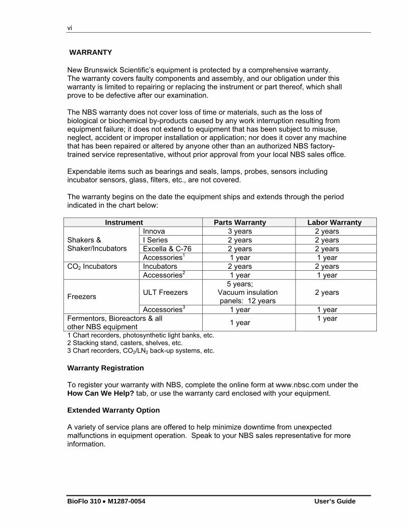
WARRANTY New Brunswick Scientific’s equipment is protected by a comprehensive warranty. The warranty covers faulty components and assembly, and our obligation under this warranty is limited to repairing or replacing the instrument or part thereof, which shall prove to be defective after our examination. The NBS warranty does not cover loss of time or materials, such as the loss of biological or biochemical by-products caused by any work interruption resulting from equipment failure; it does not extend to equipment that has been subject to misuse, neglect, accident or improper installation or application; nor does it cover any machine that has been repaired or altered by anyone other than an authorized NBS factory-trained service representative, without prior approval from your local NBS sales office. Expendable items such as bearings and seals, lamps, probes, sensors including incubator sensors, glass, filters, etc., are not covered. The warranty begins on the date the equipment ships and extends through the period indicated in the chart below:
Instrument Parts Warranty Labor Warranty Innova 3 years 2 years I Series 2 years 2 years Excella & C-76 2 years 2 years
Shakers & Shaker/Incubators
Accessories1 1 year 1 year Incubators 2 years 2 years CO2 Incubators Accessories2 1 year 1 year
ULT Freezers 5 years;
Vacuum insulation panels: 12 years
2 years Freezers
Accessories3 1 year 1 year Fermentors, Bioreactors & all other NBS equipment
1 year 1 year
1 Chart recorders, photosynthetic light banks, etc. 2 Stacking stand, casters, shelves, etc. 3 Chart recorders, CO2/LN2 back-up systems, etc.
Warranty Registration To register your warranty with NBS, complete the online form at www.nbsc.com under the How Can We Help? tab, or use the warranty card enclosed with your equipment. Extended Warranty Option A variety of service plans are offered to help minimize downtime from unexpected malfunctions in equipment operation. Speak to your NBS sales representative for more information.
vii
New Brunswick Scientific User’s Guide
FERMENTOR/BIOREACTOR
INFORMATION SHEET
On this page, record the information for your fermentor/bioreactor and retain this for future reference. MODEL NUMBER: ________________________________ VOLTAGE: ________________________________ SERIAL NUMBER: ________________________________
The above information can be found on the electrical specification plate. Purchased with the following installed options:
__________________________________________________ __________________________________________________ __________________________________________________ __________________________________________________ __________________________________________________
viii
BioFlo 310 M1287-0054 User’s Guide
TABLE OF CONTENTS
1 WARNINGS & CAUTIONS ........................................................................................... 1
1.1 WARNINGS .............................................................................................................. 1 1.2 CAUTIONS................................................................................................................ 2
2 INSPECTION & UNPACKING OF EQUIPMENT..................................................... 4
2.1 INSPECTION OF BOX(ES) .............................................................................................. 4 2.2 PACKING LIST VERIFICATION...................................................................................... 4 2.3 BASIC COMPONENTS ................................................................................................... 4
3 INTRODUCTION & OVERVIEW................................................................................ 5
3.1 SYSTEM....................................................................................................................... 5 3.2 VESSELS...................................................................................................................... 5 3.3 AGITATION SYSTEM .................................................................................................... 5 3.4 TEMPERATURE CONTROL ............................................................................................ 6 3.5 AERATION ................................................................................................................... 6 3.6 PH CONTROL ............................................................................................................... 6 3.7 DO CONTROL.............................................................................................................. 7 3.8 HIGH FOAM CONTROL................................................................................................. 7 3.9 EXHAUST SYSTEM....................................................................................................... 7 3.10 SAMPLING SYSTEM...................................................................................................... 7 3.11 RECOMMENDED ACCESSORIES & SUPPLIES................................................................. 8 3.12 SUPERVISORY SOFTWARE ........................................................................................... 8
4 INSTALLATION ............................................................................................................. 9
4.1 PHYSICAL LOCATION .................................................................................................. 9 4.2 ENVIRONMENT ............................................................................................................ 9 4.3 INSTALLING THE CONTROL CABINET........................................................................... 9 4.4 INSTALLING THE TOUCHSCREEN.................................................................................. 9 4.5 CONNECTING CONTROL CABINETS............................................................................ 11 4.6 ADDING OPTIONAL CONTROLLERS............................................................................ 12 4.7 GROUNDING STRAP ................................................................................................... 13 4.8 UTILITIES .................................................................................................................. 13
4.8.1 Electrical Requirements ................................................................................... 14 4.8.2 Water and Drain Connections.......................................................................... 14 4.8.3 Gas Connections .............................................................................................. 15
4.9 VESSEL ASSEMBLY ................................................................................................... 15 4.9.1 Insert Baffle ...................................................................................................... 18 4.9.2 Insert Impellers ................................................................................................ 18 4.9.3 Install Retention Rings ..................................................................................... 19 4.9.4 Install Sparger.................................................................................................. 20 4.9.5 Headplate Penetrations.................................................................................... 21 4.9.6 Install Harvest Tube ......................................................................................... 24 4.9.7 Insert Thermowell ............................................................................................ 25
ix
New Brunswick Scientific User’s Guide
4.9.8 Install Sampler ................................................................................................. 26 4.9.9 Install Foam/Level Probe................................................................................. 28 4.9.10 Install Headplate on Vessel.............................................................................. 29 4.9.11 Install pH Probe ............................................................................................... 30 4.9.12 Install DO Probe .............................................................................................. 30 4.9.13 Install Vessel .................................................................................................... 30 4.9.14 Install Motor Assembly..................................................................................... 30 4.9.15 Make All Connections ...................................................................................... 31
4.10 MAIN POWER SWITCH ............................................................................................... 33 4.11 OPTIONAL BIOCOMMAND SOFTWARE....................................................................... 33 4.12 INPUTS/OUTPUTS FOR ANCILLARY DEVICES ............................................................. 33
5 SPECIFICATIONS........................................................................................................ 35
5.1 CERTIFICATIONS........................................................................................................ 37
6 OPERATING CONTROLS .......................................................................................... 39
6.1 TOUCHSCREEN .......................................................................................................... 39 6.2 DISPLAY SCREENS..................................................................................................... 39
6.2.1 Touchscreen Calibration.................................................................................. 39 6.2.2 Start-Up Screen ................................................................................................ 40 6.2.3 Summary Screen............................................................................................... 40 6.2.4 Synoptic Screen ................................................................................................ 42 6.2.5 Gauge Screens.................................................................................................. 43 6.2.6 Adding Loops.................................................................................................... 43 6.2.7 Deleting Loops ................................................................................................. 45 6.2.8 Selecting Loop Control Modes......................................................................... 46 6.2.9 Calibration Screen ........................................................................................... 47 6.2.10 Cascade Screen ................................................................................................ 47 6.2.11 Trend Screen .................................................................................................... 48 6.2.12 Pumps Screen ................................................................................................... 49 6.2.13 Alarms Screen .................................................................................................. 49 6.2.14 Setup Screen ..................................................................................................... 50
6.3 RS232/422 COMPUTER INTERFACE........................................................................... 52
7 PROBE PREPARATION & CALIBRATION............................................................ 55
7.1 PH PROBE INSPECTION .............................................................................................. 55 7.2 PH PROBE CALIBRATION ........................................................................................... 55
7.2.1 pH Probe Installation....................................................................................... 57 7.2.2 pH Probe Maintenance & Storage................................................................... 58
7.3 DISSOLVED OXYGEN (DO) PROBE PREPARATION ..................................................... 58 7.3.1 Inspecting the DO Probe.................................................................................. 58 7.3.2 DO Probe Preparation..................................................................................... 59 7.3.3 DO Probe Installation...................................................................................... 59 7.3.4 DO Probe Polarization .................................................................................... 60 7.3.5 DO Probe Calibration: Setting Zero............................................................... 60 7.3.6 DO Probe Calibration: Setting Span .............................................................. 62 7.3.7 About Pump Calibration .................................................................................. 62
x
BioFlo 310 M1287-0054 User’s Guide
8 VESSEL STERILIZATION.......................................................................................... 63
8.1 INITIAL PREPARATION FOR AUTOCLAVING................................................................ 64 8.1.1 Filling the Water Jacket ................................................................................... 64
8.2 ADDITIONAL PREPARATION FOR AUTOCLAVING ....................................................... 65 8.3 AUTOCLAVING THE VESSEL ...................................................................................... 66
8.3.1 Sterilization Time and Temperature................................................................. 67
9 REINSTALLING THE VESSEL ASSEMBLY .......................................................... 68
9.1 REINSTALL THE VESSEL ASSEMBLY.......................................................................... 68 9.2 LOAD PUMP TUBING ................................................................................................. 69 9.3 CONFIRM PH CALIBRATION....................................................................................... 70 9.4 INSTALL LIQUID ADDITION SYSTEMS........................................................................ 71
9.4.1 Addition Tubing Size ........................................................................................ 71 9.5 RECONNECT GASES ................................................................................................... 72 9.6 INSTALL TEMPERATURE (RTD) PROBE ..................................................................... 73
10 GETTING STARTED ............................................................................................... 74
10.1 CONTROL MODES...................................................................................................... 74 10.2 SETTING P & I VALUES ............................................................................................. 74 10.3 LOOP SETPOINTS ....................................................................................................... 74
10.3.1 Entering Setpoints ............................................................................................ 74 10.3.2 Modifying Setpoints.......................................................................................... 75
10.4 DO CASCADE SYSTEM .............................................................................................. 76 10.5 PUMP ASSIGNMENT ................................................................................................... 76 10.6 USING LEVEL PROBES TO PROGRAM FEED PUMPS .................................................... 77
10.6.1 Setting a Feed Pump to Add Liquid ................................................................. 77 10.6.2 Setting a Feed Pump to Harvest....................................................................... 78 10.6.3 Level Control Off.............................................................................................. 79 10.6.4 Pump Calibration............................................................................................. 79
11 CASCADE CONTROL ............................................................................................. 80
11.1 CREATING A CASCADE .............................................................................................. 80 11.2 CONTROLLING DO BY CASCADE ............................................................................... 82
12 PLOTTING TRENDS................................................................................................ 85
12.1 CREATING A TREND GRAPH ...................................................................................... 85 12.1.1 Using the Export Button................................................................................... 87 12.1.2 Using the Zoom Button..................................................................................... 88 12.1.3 Using the Read Line ......................................................................................... 88
13 ABOUT PUMPS......................................................................................................... 90
13.1 PUMP SETPOINT......................................................................................................... 91 13.2 PUMP CONTROL MODE.............................................................................................. 91 13.3 PUMP FLOW RATE & CALIBRATION METHODS ......................................................... 92 13.4 PUMP PERIOD ............................................................................................................ 93 13.5 INSTALLING AN EXTERNAL VARIABLE SPEED PUMP ................................................. 94
xi
New Brunswick Scientific User’s Guide
14 ABOUT ALARMS ..................................................................................................... 96
14.1 ABS AND DEV ALARMS........................................................................................... 96 14.2 SETTING ALARMS...................................................................................................... 96 14.3 ACKNOWLEDGING AN ALARM................................................................................... 98 14.4 ALARMS HISTORY ..................................................................................................... 99
15 USING THE SETUP SCREEN............................................................................... 101
15.1 CONTROLLER SETUP ............................................................................................... 101 15.1.1 Gas Control with 1 or No TMFC ................................................................... 103 15.1.2 Gas Control with 2 TMFCs............................................................................ 103 15.1.3 Gas Control with 3 TMFCs............................................................................ 104 15.1.4 Gas Control with 4 TMFCs............................................................................ 105
15.2 RECIPE MANAGER................................................................................................... 106 15.3 SYSTEM SETTINGS................................................................................................... 107
15.3.1 Resetting Date/Time ....................................................................................... 108 15.3.2 Updating Software.......................................................................................... 109
15.4 HARDWARE SETUP .................................................................................................. 109 15.5 SECURITY SETTINGS................................................................................................ 110
16 PERFORMING A RUN........................................................................................... 113
16.1 SET UP FOAM CONTROL.......................................................................................... 113 16.2 PREPARING FOR A FERMENTATION RUN.................................................................. 113 16.3 INOCULATION.......................................................................................................... 115 16.4 START BIOCOMMAND (IF PRESENT) ........................................................................ 115 16.5 SAMPLING PROCEDURE ........................................................................................... 115 16.6 FERMENTATION PHASES.......................................................................................... 116
16.6.1 Lag Phase....................................................................................................... 116 16.6.2 Exponential Growth Phase............................................................................. 116 16.6.3 Steady State Phase ......................................................................................... 116 16.6.4 Decline Phase................................................................................................. 116
16.7 BATCH OPERATION ................................................................................................. 116 16.8 FED BATCH OPERATION .......................................................................................... 116 16.9 CONTINUOUS OPERATION ....................................................................................... 117 16.10 ANAEROBIC AND MICROAEROPHILIC CULTURE .................................................. 118 16.11 HARVESTING PROCEDURE ................................................................................... 118 16.12 SHUTDOWN PROCEDURE ..................................................................................... 119
17 ESSENTIAL OPERATING TIPS .......................................................................... 120
17.1 PRECAUTIONS FOR GLASS VESSEL ASSEMBLY ........................................................ 120 17.2 EXHAUST CONDENSER & EXHAUST FILTERS........................................................... 120 17.3 INSTALL A DOUBLE FILTER SYSTEM ....................................................................... 121 17.4 ADAPTING THE MOTOR TO BIOFLO 3000 VESSELS ................................................. 121
18 CLEANING .............................................................................................................. 122
18.1 CLEANING THE VESSEL ........................................................................................... 122 18.1.1 List of Wetted Parts ........................................................................................ 122
18.2 CLEANING THE CABINET ......................................................................................... 123
xii
BioFlo 310 M1287-0054 User’s Guide
19 MAINTENANCE ..................................................................................................... 124
19.1 PH PROBE MAINTENANCE AND STORAGE................................................................ 124 19.2 DO PROBE MAINTENANCE AND STORAGE .............................................................. 124 19.3 VESSEL & TUBING................................................................................................... 125 19.4 PERIODIC INSPECTION ............................................................................................. 125 19.5 AGITATOR BEARING HOUSING ................................................................................ 125
19.5.1 Motor Assembly Replacement ........................................................................ 125 19.6 FUSE REPLACEMENT ............................................................................................... 125 19.7 REPLACEMENT PARTS ............................................................................................. 126
20 SERVICE .................................................................................................................. 129
20.1 TROUBLESHOOTING................................................................................................. 129
21 DRAWINGS ............................................................................................................. 131
21.1 LIST OF DRAWINGS ................................................................................................. 133 21.2 LIST OF TABLES....................................................................................................... 135
22 APPENDIX A: MICROBIAL TO CELL CULTURE CONVERSION KIT .... 136
22.1 FOR GAS OVERLAY ONLY....................................................................................... 137 22.2 FOR CONVERSION FROM FERMENTATION TO CELL CULTURE.................................. 137
23 APPENDIX B: SOME GENERAL CONCEPTS................................................. 139
23.1 WHAT IS A CONTROLLER?....................................................................................... 139 23.2 WHAT IS A CONTROL LOOP? ................................................................................... 139 23.3 WHAT IS PROBE CALIBRATION? .............................................................................. 140 23.4 WHAT ARE P-I-D CONSTANTS?............................................................................... 140 23.5 WHAT IS P-I-D TUNING?......................................................................................... 141 23.6 WHAT DO THE CONSTANTS MEAN? ........................................................................ 142
24 APPENDIX C: OTR ............................................................................................... 143
24.1 DETERMINING AN OXYGEN TRANSFER RATE .......................................................... 143 24.1.1 OTR Calculations........................................................................................... 143
24.2 SOME FACTORS THAT AFFECT OTR AND HORSEPOWER......................................... 144
25 APPENDIX D: FERMENTATION TECHNIQUES ........................................... 146
25.1 MEDIA FORMULATION ............................................................................................ 146 25.2 ANTIFOAM FORMULATION ...................................................................................... 147 25.3 TUBING SIZE............................................................................................................ 147 25.4 ACID & BASE .......................................................................................................... 148 25.5 GLUCOSE FEED........................................................................................................ 148 25.6 RECOMMENDED PROCESS CONTROL SETTINGS ....................................................... 149 25.7 TYPICAL FERMENTATION RUN ................................................................................ 149
25.7.1 Vessel Preparation Before Autoclaving ......................................................... 149 25.7.2 Vessel Sterilization ......................................................................................... 151 25.7.3 Post-Sterilization Vessel Set-Up..................................................................... 152 25.7.4 Vessel Operation ............................................................................................ 153 25.7.5 Vessel Shutdown & Cleaning ......................................................................... 153

xiii
New Brunswick Scientific User’s Guide
26 APPENDIX E: CORROSION RESISTANCE ..................................................... 157
27 APPENDIX F: GENERAL CHARACTERISTICS OF EPR ............................. 158
27.1 IDENTIFYING EPR ................................................................................................... 158 27.2 GENERAL CHARACTERISTICS .................................................................................. 158
28 INDEX ....................................................................................................................... 159

1
New Brunswick Scientific User’s Guide
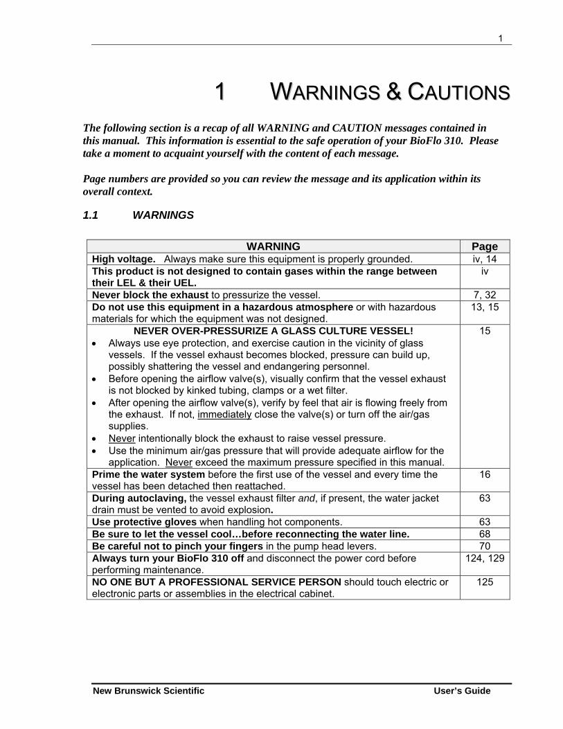
11 WWAARRNNIINNGGSS && CCAAUUTTIIOONNSS The following section is a recap of all WARNING and CAUTION messages contained in this manual. This information is essential to the safe operation of your BioFlo 310. Please take a moment to acquaint yourself with the content of each message. Page numbers are provided so you can review the message and its application within its overall context.
1.1 WARNINGS
WARNING Page
High voltage. Always make sure this equipment is properly grounded. iv, 14 This product is not designed to contain gases within the range between their LEL & their UEL.
iv
Never block the exhaust to pressurize the vessel. 7, 32 Do not use this equipment in a hazardous atmosphere or with hazardous materials for which the equipment was not designed.
13, 15
NEVER OVER-PRESSURIZE A GLASS CULTURE VESSEL! Always use eye protection, and exercise caution in the vicinity of glass
vessels. If the vessel exhaust becomes blocked, pressure can build up, possibly shattering the vessel and endangering personnel.
Before opening the airflow valve(s), visually confirm that the vessel exhaust is not blocked by kinked tubing, clamps or a wet filter.
After opening the airflow valve(s), verify by feel that air is flowing freely from the exhaust. If not, immediately close the valve(s) or turn off the air/gas supplies.
Never intentionally block the exhaust to raise vessel pressure. Use the minimum air/gas pressure that will provide adequate airflow for the
application. Never exceed the maximum pressure specified in this manual.
15
Prime the water system before the first use of the vessel and every time the vessel has been detached then reattached.
16
During autoclaving, the vessel exhaust filter and, if present, the water jacket drain must be vented to avoid explosion.
63
Use protective gloves when handling hot components. 63 Be sure to let the vessel cool…before reconnecting the water line. 68 Be careful not to pinch your fingers in the pump head levers. 70 Always turn your BioFlo 310 off and disconnect the power cord before performing maintenance.
124, 129
NO ONE BUT A PROFESSIONAL SERVICE PERSON should touch electric or electronic parts or assemblies in the electrical cabinet.
125
2
BioFlo 310 M1287-0054 User’s Guide
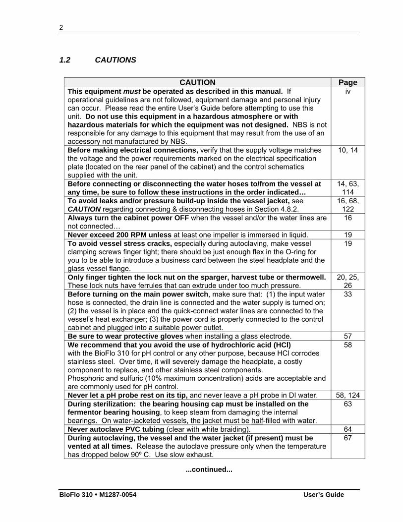
1.2 CAUTIONS
CAUTION Page
This equipment must be operated as described in this manual. If operational guidelines are not followed, equipment damage and personal injury can occur. Please read the entire User’s Guide before attempting to use this unit. Do not use this equipment in a hazardous atmosphere or with hazardous materials for which the equipment was not designed. NBS is not responsible for any damage to this equipment that may result from the use of an accessory not manufactured by NBS.
iv
Before making electrical connections, verify that the supply voltage matches the voltage and the power requirements marked on the electrical specification plate (located on the rear panel of the cabinet) and the control schematics supplied with the unit.
10, 14
Before connecting or disconnecting the water hoses to/from the vessel at any time, be sure to follow these instructions in the order indicated…
14, 63, 114
To avoid leaks and/or pressure build-up inside the vessel jacket, see CAUTION regarding connecting & disconnecting hoses in Section 4.8.2.
16, 68, 122
Always turn the cabinet power OFF when the vessel and/or the water lines are not connected…
16
Never exceed 200 RPM unless at least one impeller is immersed in liquid. 19 To avoid vessel stress cracks, especially during autoclaving, make vessel clamping screws finger tight; there should be just enough flex in the O-ring for you to be able to introduce a business card between the steel headplate and the glass vessel flange.
19
Only finger tighten the lock nut on the sparger, harvest tube or thermowell. These lock nuts have ferrules that can extrude under too much pressure.
20, 25, 26
Before turning on the main power switch, make sure that: (1) the input water hose is connected, the drain line is connected and the water supply is turned on; (2) the vessel is in place and the quick-connect water lines are connected to the vessel’s heat exchanger; (3) the power cord is properly connected to the control cabinet and plugged into a suitable power outlet.
33
Be sure to wear protective gloves when installing a glass electrode. 57 We recommend that you avoid the use of hydrochloric acid (HCl) with the BioFlo 310 for pH control or any other purpose, because HCl corrodes stainless steel. Over time, it will severely damage the headplate, a costly component to replace, and other stainless steel components. Phosphoric and sulfuric (10% maximum concentration) acids are acceptable and are commonly used for pH control.
58
Never let a pH probe rest on its tip, and never leave a pH probe in DI water. 58, 124 During sterilization: the bearing housing cap must be installed on the fermentor bearing housing, to keep steam from damaging the internal bearings. On water-jacketed vessels, the jacket must be half-filled with water.
63
Never autoclave PVC tubing (clear with white braiding). 64 During autoclaving, the vessel and the water jacket (if present) must be vented at all times. Release the autoclave pressure only when the temperature has dropped below 90º C. Use slow exhaust.
67
...continued...
3
New Brunswick Scientific User’s Guide
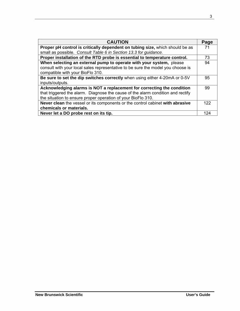
CAUTION Page Proper pH control is critically dependent on tubing size, which should be as small as possible. Consult Table 6 in Section 13.3 for guidance.
71
Proper installation of the RTD probe is essential to temperature control. 73 When selecting an external pump to operate with your system, please consult with your local sales representative to be sure the model you choose is compatible with your BioFlo 310.
94
Be sure to set the dip switches correctly when using either 4-20mA or 0-5V inputs/outputs.
95
Acknowledging alarms is NOT a replacement for correcting the condition that triggered the alarm. Diagnose the cause of the alarm condition and rectify the situation to ensure proper operation of your BioFlo 310.
99
Never clean the vessel or its components or the control cabinet with abrasive chemicals or materials.
122
Never let a DO probe rest on its tip. 124
4
BioFlo 310 M1287-0054 User’s Guide
22 IINNSSPPEECCTTIIOONN && UUNNPPAACCKKIINNGG OOFF
EEQQUUIIPPMMEENNTT
2.1 Inspection of Box(es)
When you have received your order from New Brunswick Scientific, carefully inspect all parts of the shipment for damage that may have occurred during shipping. Report any damage immediately to the carrier and to your local NBS Sales Order Department.
2.2 Packing List Verification
Verify against your NBS packing list that you have received the correct materials. Report any missing parts to your local NBS Sales Order Department.
2.3 Basic Components
You should have at least the following components, which will be described in greater detail later in this manual:
Control Cabinet Motor Touchscreen* Bearing Housing Vessel Filters & connectors Thermowell & RTD Inoculation/Addition System Baffles Sampling System Impellers Harvesting System Probe Kits (i.e., pH, DO, Foam, Level) Sparging System
*While you may have multiple units, each with its own components, you will have ordered only one touchscreen.
NOTE: The assembled Control Cabinet/Touchscreen assembly is called a Control Station. For purposes of clarity in this manual, however, the control cabinet (which houses the controller) and the touchscreen will be referred to separately by their component names.
5
New Brunswick Scientific User’s Guide
33 IINNTTRROODDUUCCTTIIOONN && OOVVEERRVVIIEEWW
3.1 System
BioFlo 310 is a versatile fermentor/bioreactor that provides a fully equipped system in one compact package. It can be employed for batch, fed batch or continuous culture with process control for pH, dissolved oxygen (DO), agitation, temperature, pump feed, antifoam, foam/level, and additional analog/digital inputs and outputs. Systems can be configured as either control stations or utility stations. Each individual stand-alone system is a control station. One master control station can control up to three additional utility fermentor systems, which are dependent on the control station.
3.2 Vessels
The fermentation vessels are designed for total volumes of 2.5, 5.0, 7.5 and 14.0 liters. Each vessel consists of a stainless steel headplate, a flanged glass tube (thick-walled) vessel body which is detachable from the stainless steel bottom-dished head. The dished head is jacketed for the circulation of temperature-controlled water. Ports in the headplate are provided for, but not limited to, the following purposes: inoculation; base and acid addition; a thermowell for a resistance temperature detector (RTD); a foam probe; a sparger; a harvest tube; a sampling tube; an exhaust condenser; and dissolved oxygen (DO) and pH electrodes. The drive bearing housing is also located on the headplate (see Figures 3a, 8, 9 and 10).
3.3 Agitation System
A removable agitation motor located on top of the bearing housing on the headplate is connected to the agitation shaft with a multi-jaw coupling for fermentation.
It can be easily disconnected for autoclaving the vessel and easily replaced after sterilization. The motor will provide a speed range from 50 to 1200 RPM. The process control software ensures agitation speed control throughout the speed range. It is possible to cascade Dissolved Oxygen (DO) to Agitation (AGIT) so the agitation speed will vary between the user-specified minimum and maximum setpoints in order to maintain the set percentage of DO. (See Section 11 for further information on setting up cascades.)
Default P & I (proportional & integral) values are preset at the factory. We strongly recommend that you maintain the factory-set parameters.
6
BioFlo 310 M1287-0054 User’s Guide
3.4 Temperature Control
The culture temperature setpoint may be selected within the range from 5C above coolant temperature to 80C ( 0.1C). It is controlled by the process control software. The media temperature is sensed by a Resistance Temperature Detector (RTD) submerged in the thermowell (see Figure 9).
Default P & I (proportional & integral) values are preset at the factory. We strongly recommend that you maintain the factory-set parameters.
3.5 Aeration
You will regulate the airflow rate by inputting values through the touchscreen on the control cabinet.
Up to four gases, including air, nitrogen, carbon dioxide and oxygen, can be introduced into the media through the ring sparger. The flow rate is controlled automatically by one, two, three or four thermal mass flow controller(s), according to the definition of your system. The thermal mass flow controller is regulated automatically according to values set via the control cabinet touchscreen. If you wish to use a rotameter, there is an option for no thermal mass flow controller.
The percentage of oxygen blended with the sparge air can be controlled manually by the user or automatically through the controller by applying the O2 enrichment function. (For further information on cascading, see Section 11.) Default P & I (proportional & integral) values are preset at the factory. We strongly recommend that you maintain the factory-set parameters.
3.6 pH Control
pH is controlled in the range of 2.00-12.00 ( 0.01). The pH is sensed by a Gel-filled pH probe (see Figures 34a & 34b). Control is maintained by a P & I (proportional & integral) controller which operates two peristaltic pumps, assigned to acid and base addition ports, or controls the use of gas(es) for this purpose. The user can also select a deadband value to control pH within the user-assigned range: no acid or base will be added when the pH value falls within the deadband tolerance above or below the setpoint.
Default P & I (proportional & integral) values are preset at the factory. We strongly recommend that you maintain the factory-set parameters.
7
New Brunswick Scientific User’s Guide
3.7 DO Control
DO is controlled in the range of 0-200% ( 1%). It is sensed by the DO electrode and control is maintained by the P & I controller by changing the speed of agitation, the thermal mass flow controller-regulated flow rate (if your system is so equipped), and/or the percentage of oxygen in aeration.
Default P & I (proportional & integral) values are preset at the factory. We strongly recommend that you maintain the factory-set parameters. The DO probe is a polarographic probe (see Figure 35).
3.8 High Foam Control
Foam can be controlled during batch fermentation by a foam/level probe (see Figure 12), located in the headplate. The controller operates the antifoam-assigned pump that adds chemical defoamer into the vessel as needed.
3.9 Exhaust System
The exhaust gases pass into the exhaust condenser (see Figures 13 and 14) where moisture is removed, then returned to the vessel. The remaining air passes through the 0.2 m exhaust filter.
WARNING! NEVER block the exhaust to pressurize the vessel! See Section 4.9 for further details.
3.10 Sampling System
SYSTEM I
This system consists of a sampler attached to a sampling tube that extends to the lower portion of the vessel (see Figure 10). The sampler has a rubber suction bulb to facilitate collection of representative samples without contamination. A 25mL or 40mL screw cap container serves as a reservoir for the sample collected.
8
BioFlo 310 M1287-0054 User’s Guide
SYSTEM II
This system consists of a sample line and a peristaltic pump (see Figure 11). The ON/OFF function of the pump serves to operate the sampling system.
3.11 Recommended Accessories & Supplies
Before you begin to assemble your BioFlo 310, it would be prudent to verify that you have all of the following accessories and supplies readily at hand:
An autoclave An inoculation syringe Rubber gloves Media Silicone tubing Antifoam agent A tie gun Aluminum foil Plastic ties Rubber bands Plastic tubing connectors pH 4 buffer Addition bottles pH 7 buffer A liquid trap Silicone O-ring lubricant A user’s kit is available from NBS with many of the commonly required items (including a selection of tubing, clamps, filters, connectors and addition vessels). Speak to your NBS sales representative for more information.
3.12 Supervisory Software
In addition to the built-in software that you interface with through the touchscreen, your BioFlo 310 system can be remotely controlled from a PC via NBS BioCommand optional supervisory software (see Section 4.11). Consult your NBS representative for details; be sure to ask for your choice of AFS or ModBus protocol.
9
New Brunswick Scientific User’s Guide
44 IINNSSTTAALLLLAATTIIOONN
4.1 Physical Location
The surface on which you place the BioFlo 310 fermentor should be smooth, level and sturdy. Ensure that the surface can bear the weight of the fermentor plus vessel contents and any applicable ancilliary equipment.
Also ensure that there is enough space around the back and the front of the BioFlo 310 for proper operation and access. Allow at least 4 inches of clearance behind the unit for heat dissipation. See Section 5, Specifications, for weights and dimensions.
4.2 Environment
The BioFlo 310 fermentor operates properly under the following conditions:
Ambient temperature range 10C to 30C Relative humidity up to 80% non-condensing
4.3 Installing the Control Cabinet
Position the BioFlo 310 control cabinet on a firm, level surface in an area where utilities are readily available. Level the horizontal surface of the base with four leveling glides if necessary. Connect the power cord to the rear of the control cabinet. At a later time, once the unit is completely assembled and all connections have been made, you will plug the power cord into a suitable electrical outlet.
4.4 Installing the Touchscreen
With reference to Figures 1a (for location) & 1b, align the monitor with the mounting rack on the cabinet, and use the four screws provided with the monitor to securely fasten it to the rack. The mounting rack swivels for easy access. With reference to Figure 1b, connect the cabinet’s power cord plug, com port connector and VGA monitor connector to the bottom of the touchscreen monitor.
10
BioFlo 310 M1287-0054 User’s Guide
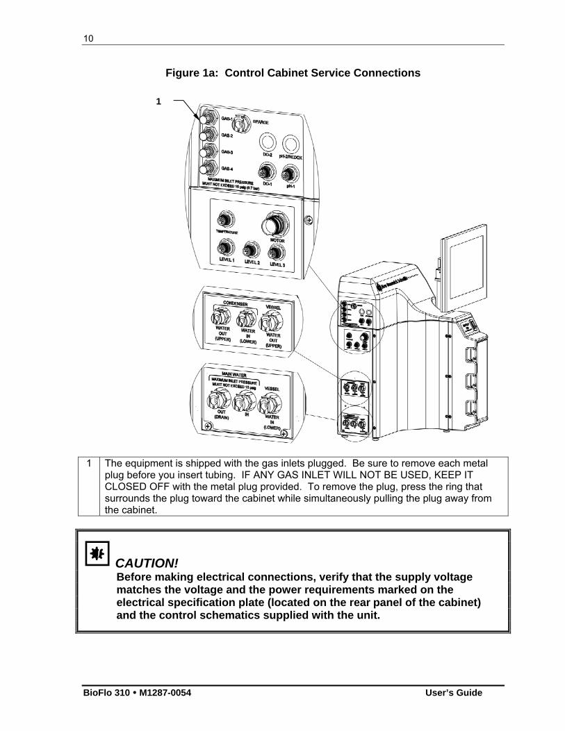
Figure 1a: Control Cabinet Service Connections
1 The equipment is shipped with the gas inlets plugged. Be sure to remove each metal
plug before you insert tubing. IF ANY GAS INLET WILL NOT BE USED, KEEP IT CLOSED OFF with the metal plug provided. To remove the plug, press the ring that surrounds the plug toward the cabinet while simultaneously pulling the plug away from the cabinet.
CAUTION! Before making electrical connections, verify that the supply voltage matches the voltage and the power requirements marked on the electrical specification plate (located on the rear panel of the cabinet) and the control schematics supplied with the unit.
1
11
New Brunswick Scientific User’s Guide
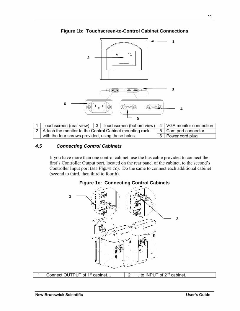
Figure 1b: Touchscreen-to-Control Cabinet Connections
1 Touchscreen (rear view) 3 Touchscreen (bottom view) 4 VGA monitor connection 5 Com port connector 2 Attach the monitor to the Control Cabinet mounting rack
with the four screws provided, using these holes. 6 Power cord plug
4.5 Connecting Control Cabinets
If you have more than one control cabinet, use the bus cable provided to connect the first’s Controller Output port, located on the rear panel of the cabinet, to the second’s Controller Input port (see Figure 1c). Do the same to connect each additional cabinet (second to third, then third to fourth).
Figure 1c: Connecting Control Cabinets
1 Connect OUTPUT of 1st cabinet… 2 …to INPUT of 2nd cabinet.
1
2
3
6 4
5
1
2
12
BioFlo 310 M1287-0054 User’s Guide
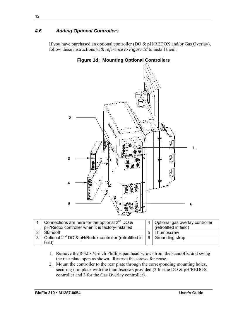
4.6 Adding Optional Controllers
If you have purchased an optional controller (DO & pH/REDOX and/or Gas Overlay), follow these instructions with reference to Figure 1d to install them:
Figure 1d: Mounting Optional Controllers
1 Connections are here for the optional 2nd DO &
pH/Redox controller when it is factory-installed 4 Optional gas overlay controller
(retrofitted in field) 2 Standoff 5 Thumbscrew 3 Optional 2nd DO & pH/Redox controller (retrofitted in
field) 6 Grounding strap
1. Remove the 8-32 x ¼-inch Phillips pan head screws from the standoffs, and swing
the rear plate open as shown. Reserve the screws for reuse. 2. Mount the controller to the rear plate through the corresponding mounting holes,
securing it in place with the thumbscrews provided (2 for the DO & pH/REDOX controller and 3 for the Gas Overlay controller).
1
2
3
4
5 6
13
New Brunswick Scientific User’s Guide
3. Swing the backplate and controller(s) back to the standoffs and reinstall the 8-32 x 1/4-inch screws.
If you have purchased the Microbial to Cell Culture/Gas Overlay Conversion Kit (NBS part number M1287-3501), see Appendix A for installation instructions.
4.7 Grounding Strap
There is a grounding strap shown in Figure 1d as anchored to the lower left mounting screw on the control cabinet’s side panel. When you install the vessel, the clip end of this grounding strap must be clipped to the vessel headplate to ground the motor to the cabinet. This is a requirement to meet safety regulations.
4.8 Utilities
WARNING! Do not use this equipment in a hazardous atmosphere or with hazardous materials for which the equipment was not designed.
The control cabinet assembly must be properly connected to gases, water supply, vessel water, electrical power and an open drain. All service connections are located on the lefthand side of the cabinet (see Figure 1a). Using standard plant practices and respecting all applicable codes, connect services to the appropriate connections, as recapped in Table 1 and explained in greater detail in Sections 4.8.1 - 4.8.3.
Table 1: Service Connections
Service/Utility Requirement Connection 100-120 VAC, 50/60 Hz., Single Phase, 15 Amp (fluctuations not to exceed ±10%)
100-120 VAC 1ph field wired to 15 Amp disconnect in panel
Electrical
208-230 VAC, 50/60 Hz., Single Phase, 15 Amp (fluctuations not to exceed ±10%)
208-230 VAC 1ph field wired to 15 Amp disconnect in panel
Water Return Maximum backpressure 5 PSIG Quick Connect Facility Water 3 GPM must be regulated to 10 PSIG Quick Connect Process Air 10 PSIG Push on Oxygen 10 PSIG Push on Nitrogen 10 PSIG Push on Carbon Dioxide 10 PSIG Push on Exhaust 1/2 PSIG maximum backpressure Quick Connect
14
BioFlo 310 M1287-0054 User’s Guide
4.8.1 Electrical Requirements
100-120 Volts 50/60 Hertz 15 Amp 208-230 Volts 50/60 Hertz 15 Amp
NOTE: The electrical requirements vary depending on the part number that has been ordered. Model, Part Number and Electrical Power Requirements for each fermentor appear on a metal label affixed to the rear of the unit just above the connection for the power cord.
CAUTION! Before making electrical connections, verify that the supply voltage matches the voltage and the power requirements marked on the electrical specification plate (located on the rear panel of the cabinet) and the control schematics supplied with the unit.
WARNING! High voltage. Always make sure this equipment is properly grounded.
4.8.2 Water and Drain Connections
The water inlet and drain connections are located on the left side of the control cabinet (see Figure 1a). Water pressure should be 10 PSIG, with 50 m filtration. Connectors are quick-connect fittings that accept a six-foot long utility hose, which is supplied with the fermentor.
CAUTION! Before connecting or disconnecting the water hoses to/from the vessel at any time, be sure to follow these instructions in the order indicated: To connect: (1) Connect vessel Water Out line, (2) Connect vessel Water In line, (3) Connect cabinet Main Water In line, (4) Turn ON main power switch on cabinet. To disconnect: (1) Turn OFF main power switch on cabinet, (2) Disconnect Main Water In line from cabinet, (3) Disconnect vessel Water In line,
(4) Disconnect vessel Water Out line. Failure to heed these instructions may lead to hose leakage and/or pressure build-up
inside the vessel jacket.
15
New Brunswick Scientific User’s Guide
4.8.3 Gas Connections
Gas inlets are located on the left side of the control cabinet (see Figure 1a). There are push-in connectors for air, nitrogen, oxygen and carbon dioxide. These connectors accept flexible tubing (NBS Part No.P0740-3113C3 polyurethane tubing); tubing is supplied with the fermentor. Other soft, flexible-walled, chemically inert tubing (such as Marprene, Pharmed, etc.) may be used as well. Be sure to remove the metal inlet plug first.
WARNING! • Do not use this equipment in a hazardous atmosphere or with hazardous materials for which the equipment was not designed. • All gases supplied should be medical grade. • No gas pressure should rise above 10 PSIG (see also page iv). • Never leave a gas inlet open; if no tubing will be connected, keep the inlet plugged.
All gases should be regulated using a two-stage regulator. The scale of the regulator gauge for gases going into the fermentor should be such that one can regulate pressure between 0-10 PSIG maximum.
4.9 Vessel Assembly
WARNING!
NEVER OVER-PRESSURIZE A GLASS CULTURE VESSEL!
Always use eye protection, and exercise caution in the vicinity of glass vessels. If the vessel exhaust becomes blocked, pressure can build up, possibly shattering the vessel and endangering personnel.
Before opening the airflow valve(s), visually confirm that the vessel exhaust is not blocked by kinked tubing, clamps or a wet filter.
After opening the airflow valve(s), verify by feel that air is flowing freely from the exhaust. If not, immediately close the valve(s) or turn off the air/gas supplies.
Never intentionally block the exhaust to raise vessel pressure. Use the minimum air/gas pressure that will provide adequate airflow for the
application. Never exceed the maximum pressure specified in this manual.
16
BioFlo 310 M1287-0054 User’s Guide
NOTE: Clean the vessel thoroughly after each run with detergent, otherwise debris will build up thus providing a place for bacteria to grow and produce toxins. This can result in low cell viability.
CAUTION! To avoid leaks and/or pressure build-up inside the vessel jacket, see CAUTION regarding connecting & disconnecting hoses in Section 4.8.2.
CAUTION! Always turn the cabinet power OFF when the vessel and/or the water lines are not connected to the supply or the vessel. Failure to do this will result in premature failure of the pump.
WARNING! Prime the water system before the first use of the vessel and every time the vessel has been detached then reattached. To prime the water system: Make sure all water connections are intact. Set the Temp setpoint (see Section 10.3.1) 10°C below process value. Turn Temp to AUTO for 3 minutes (see Section 10.1) to run 100% cooling. The cooling water will drive out any air that was left in the water system lines and the vessel heat exchanger.
1. Clean the jacketed glass vessel with a cell culture compatible detergent. After cleaning, rinse several times with distilled water.
2. If microcarriers are being used, the glass vessel should be siliconized. A silicone solution such as Sigmacote may be used according to the manufacturer's instructions.
17
New Brunswick Scientific User’s Guide
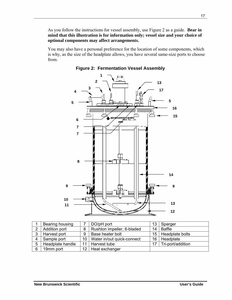
As you follow the instructions for vessel assembly, use Figure 2 as a guide. Bear in mind that this illustration is for information only; vessel size and your choice of optional components may affect arrangements.
You may also have a personal preference for the location of some components, which is why, as the size of the headplate allows, you have several same-size ports to choose from.
Figure 2: Fermentation Vessel Assembly
1 Bearing housing 7 DO/pH port 13 Sparger 2 Addition port 8 Rushton impeller, 6-bladed 14 Baffle 3 Harvest port 9 Base heater bolt 15 Headplate bolts 4 Sample port 10 Water in/out quick-connect 16 Headplate 5 Headplate handle 11 Harvest tube 17 Tri-port/addition 6 19mm port 12 Heat exchanger
1
2
3 4
5 5
16
15
17
13
6
7
7
8
9 9
10
11
12
13
14
18
BioFlo 310 M1287-0054 User’s Guide
If you need to insert the baffle (see Section 4.9.1) and/or impellers (see Section 4.9.2), remove the headplate by unscrewing the headbolts, each a little at a time, working diagonally rather than around in a circle. Set the headbolts aside for reuse. Carefully lift the headplate (using the handles if they are present) and set it aside.
4.9.1 Insert Baffle
For fermentation only: If you are using a baffle, and it is not already installed, install the baffle assembly inside the glass vessel by gently compressing the baffle ring at its ends and then sliding the assembly into the vessel until it rests on the bottom. Make sure the baffle’s vertical opening faces the location where you plan to install the pH and DO probes.
4.9.2 Insert Impellers
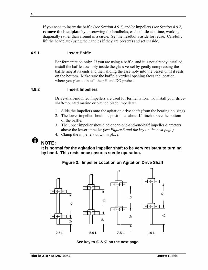
Drive-shaft-mounted impellers are used for fermentation. To install your drive-shaft-mounted marine or pitched blade impellers:
1. Slide the impellers onto the agitation drive shaft (from the bearing housing). 2. The lower impeller should be positioned about 1/4 inch above the bottom
of the baffle. 3. The upper impeller should be one to one-and-one-half impeller diameters
above the lower impeller (see Figure 3 and the key on the next page). 4. Clamp the impellers down in place.
NOTE: It is normal for the agitation impeller shaft to be very resistant to turning by hand. This resistance ensures sterile operation.
See key to & on the next page.
Figure 3: Impeller Location on Agitation Drive Shaft
2.5 L 5.0 L 7.5 L 14 L
19
New Brunswick Scientific User’s Guide
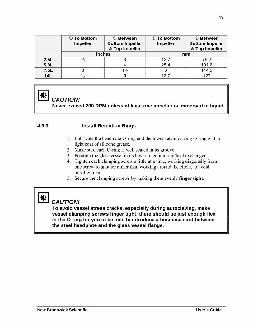
To Bottom
Impeller
Between Bottom Impeller & Top Impeller
To Bottom Impeller
Between Bottom Impeller & Top Impeller
inches mm 2.5L ½ 3 12.7 76.2 5.0L 1 4 25.4 101.6 7.5L 0 4½ 0 114.3 14L ½ 5 12.7 127
CAUTION! Never exceed 200 RPM unless at least one impeller is immersed in liquid.
4.9.3 Install Retention Rings
1. Lubricate the headplate O-ring and the lower retention ring O-ring with a light coat of silicone grease.
2. Make sure each O-ring is well seated in its groove. 3. Position the glass vessel in its lower retention ring/heat exchanger. 4. Tighten each clamping screw a little at a time, working diagonally from
one screw to another rather than working around the circle, to avoid misalignment.
5. Secure the clamping screws by making them evenly finger tight.
CAUTION! To avoid vessel stress cracks, especially during autoclaving, make vessel clamping screws finger tight; there should be just enough flex in the O-ring for you to be able to introduce a business card between the steel headplate and the glass vessel flange.
20
BioFlo 310 M1287-0054 User’s Guide
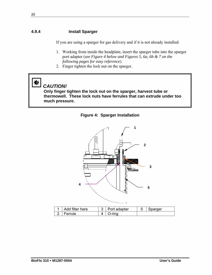
4.9.4 Install Sparger If you are using a sparger for gas delivery and if it is not already installed: 1. Working from inside the headplate, insert the sparger tube into the sparger
port adapter (see Figure 4 below and Figures 5, 6a, 6b & 7 on the following pages for easy reference).
2. Finger tighten the lock nut on the sparger.
CAUTION! Only finger tighten the lock nut on the sparger, harvest tube or thermowell. These lock nuts have ferrules that can extrude under too much pressure.
Figure 4: Sparger Installation
1 Add filter here 3 Port adapter 5 Sparger 2 Ferrule 4 O-ring
1
3
5
2
4
21
New Brunswick Scientific User’s Guide
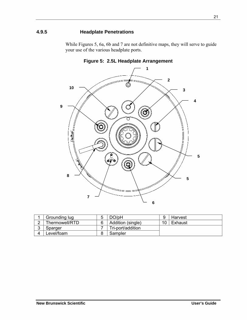
4.9.5 Headplate Penetrations While Figures 5, 6a, 6b and 7 are not definitive maps, they will serve to guide your use of the various headplate ports.
Figure 5: 2.5L Headplate Arrangement
1 Grounding lug 5 DO/pH 9 Harvest 2 Thermowell/RTD 6 Addition (single) 10 Exhaust 3 Sparger 7 Tri-port/addition 4 Level/foam 8 Sampler
1
2
3
4
5
5
6
7
8
9
10
22
BioFlo 310 M1287-0054 User’s Guide
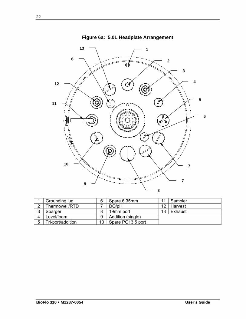
Figure 6a: 5.0L Headplate Arrangement
1 Grounding lug 6 Spare 6.35mm 11 Sampler 2 Thermowell/RTD 7 DO/pH 12 Harvest 3 Sparger 8 19mm port 13 Exhaust 4 Level/foam 9 Addition (single) 5 Tri-port/addition 10 Spare PG13.5 port
1
2
3
4
7
7 9
5 11
12
13
6
8
10
6
23
New Brunswick Scientific User’s Guide
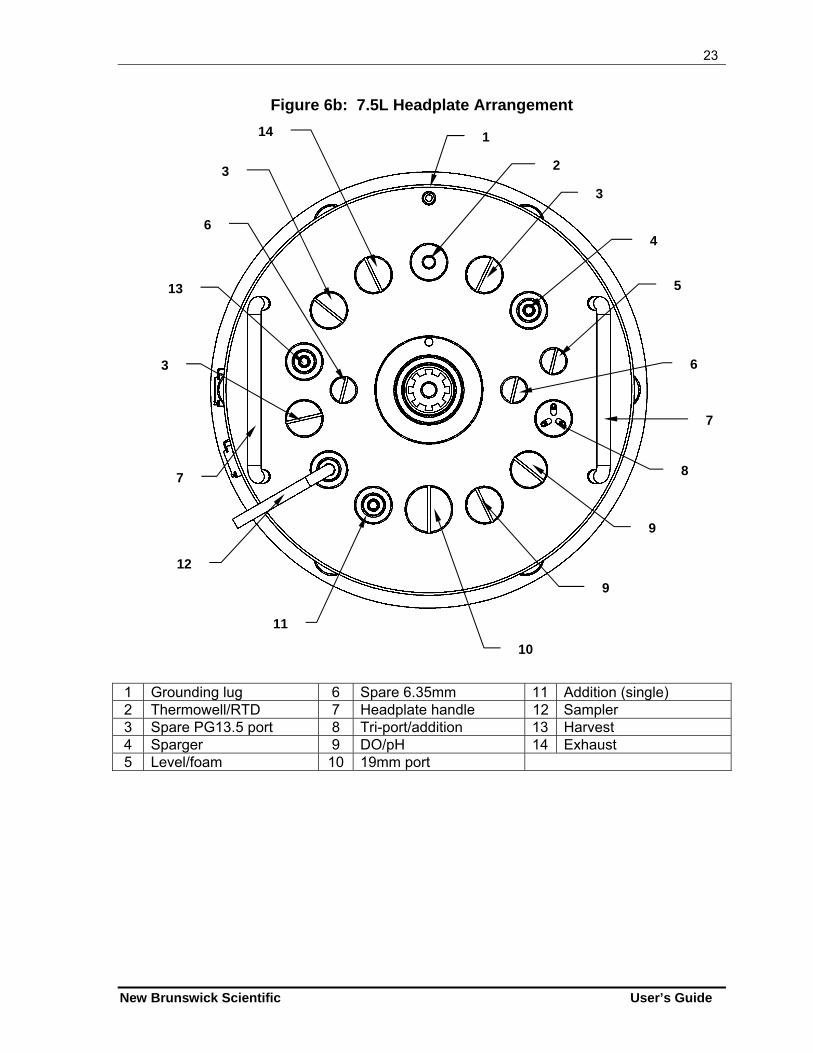
Figure 6b: 7.5L Headplate Arrangement
1 Grounding lug 6 Spare 6.35mm 11 Addition (single) 2 Thermowell/RTD 7 Headplate handle 12 Sampler 3 Spare PG13.5 port 8 Tri-port/addition 13 Harvest 4 Sparger 9 DO/pH 14 Exhaust 5 Level/foam 10 19mm port
1
2
4
5
9
9
11
8
12
13
14
6
10
3
6
7
3
3
7
24
BioFlo 310 M1287-0054 User’s Guide
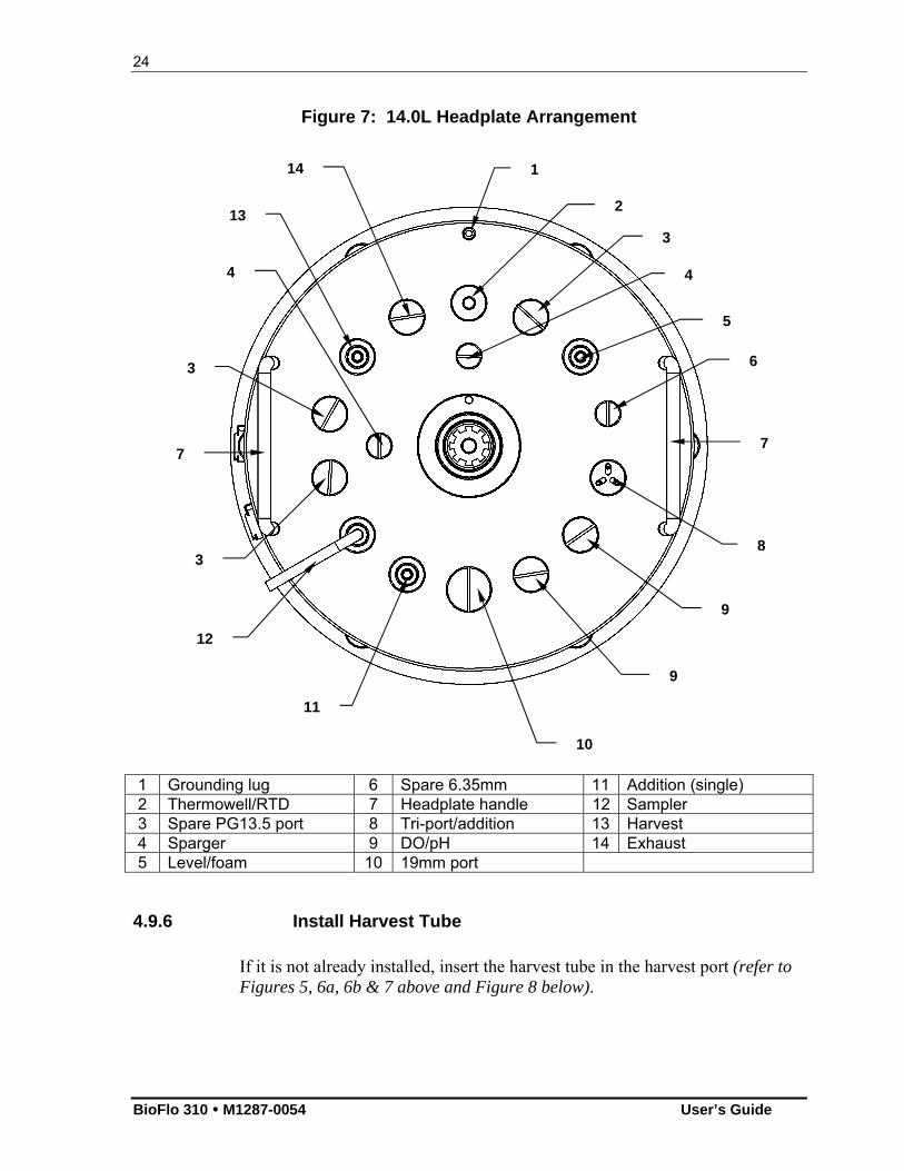
Figure 7: 14.0L Headplate Arrangement
1 Grounding lug 6 Spare 6.35mm 11 Addition (single) 2 Thermowell/RTD 7 Headplate handle 12 Sampler 3 Spare PG13.5 port 8 Tri-port/addition 13 Harvest 4 Sparger 9 DO/pH 14 Exhaust 5 Level/foam 10 19mm port
4.9.6 Install Harvest Tube
If it is not already installed, insert the harvest tube in the harvest port (refer to Figures 5, 6a, 6b & 7 above and Figure 8 below).
1
2
5
6
9
9
11
8
12
13
14
4
10
3
4
7
3
3
7
25
New Brunswick Scientific User’s Guide
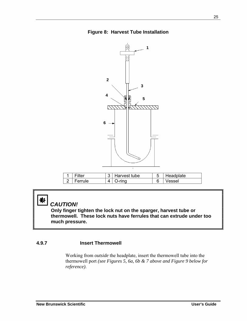
Figure 8: Harvest Tube Installation
1 Filter 3 Harvest tube 5 Headplate 2 Ferrule 4 O-ring 6 Vessel
CAUTION! Only finger tighten the lock nut on the sparger, harvest tube or thermowell. These lock nuts have ferrules that can extrude under too much pressure.
4.9.7 Insert Thermowell
Working from outside the headplate, insert the thermowell tube into the thermowell port (see Figures 5, 6a, 6b & 7 above and Figure 9 below for reference).
FERRULE
4
1
2
3
5
6
26
BioFlo 310 M1287-0054 User’s Guide
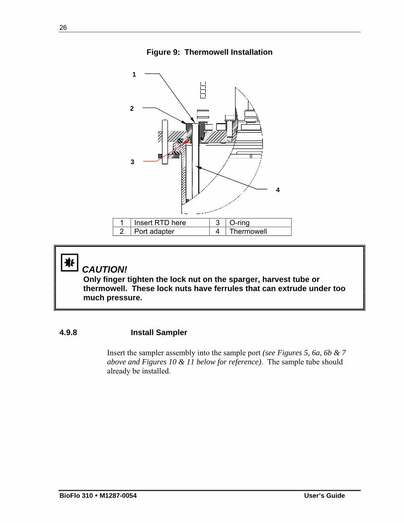
Figure 9: Thermowell Installation
1 Insert RTD here 3 O-ring 2 Port adapter 4 Thermowell
CAUTION! Only finger tighten the lock nut on the sparger, harvest tube or thermowell. These lock nuts have ferrules that can extrude under too much pressure.
4.9.8 Install Sampler
Insert the sampler assembly into the sample port (see Figures 5, 6a, 6b & 7 above and Figures 10 & 11 below for reference). The sample tube should already be installed.
4
2
3
1
27
New Brunswick Scientific User’s Guide
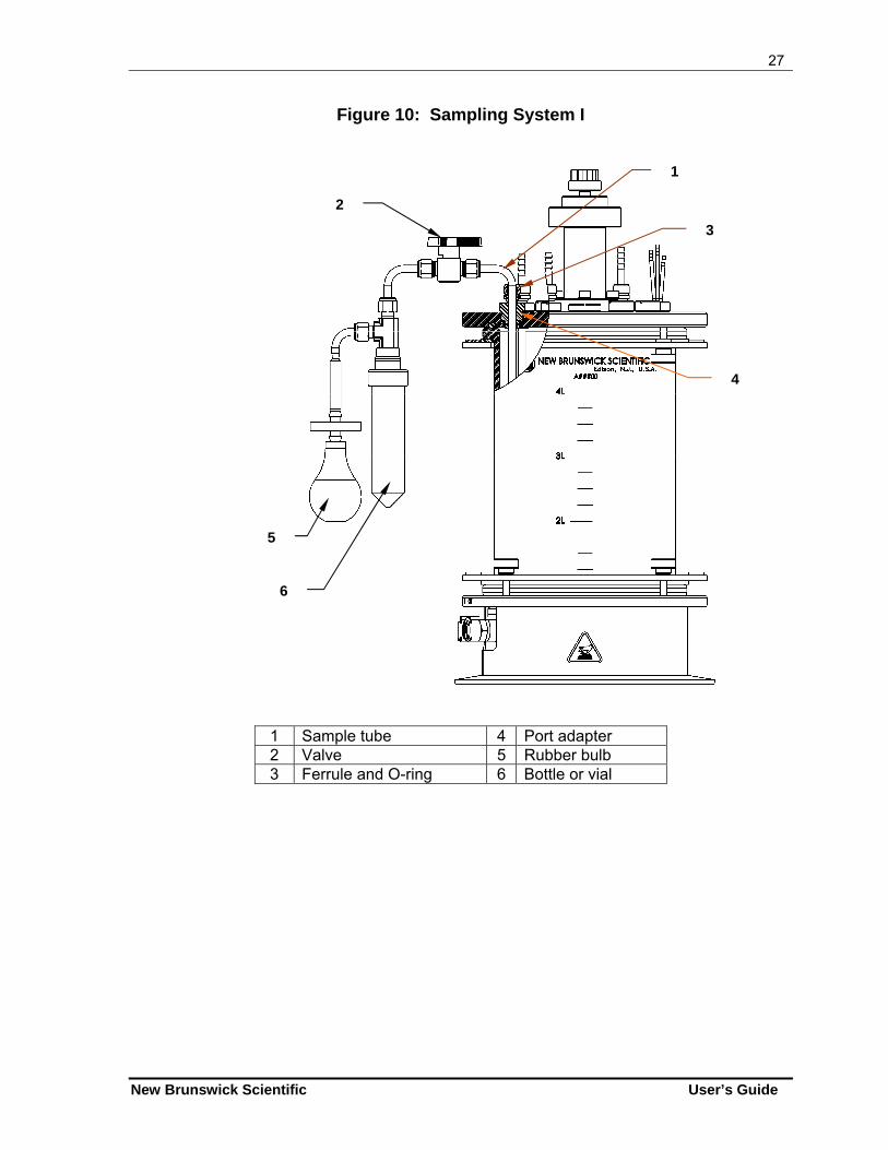
Figure 10: Sampling System I
1 Sample tube 4 Port adapter 2 Valve 5 Rubber bulb 3 Ferrule and O-ring 6 Bottle or vial
5
6
2
1
3
4
28
BioFlo 310 M1287-0054 User’s Guide
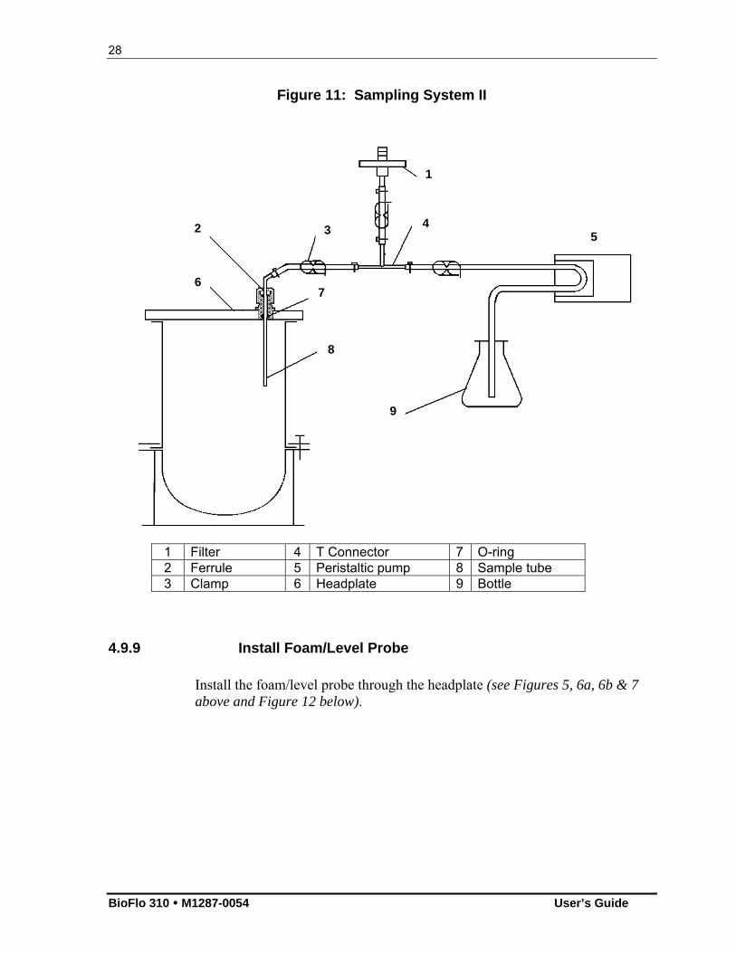
Figure 11: Sampling System II
1 Filter 4 T Connector 7 O-ring 2 Ferrule 5 Peristaltic pump 8 Sample tube 3 Clamp 6 Headplate 9 Bottle
4.9.9 Install Foam/Level Probe
Install the foam/level probe through the headplate (see Figures 5, 6a, 6b & 7 above and Figure 12 below).
FERRULE “T” CONNECTOR
O-RING
1
2 3 4
5
6 7
8
9
29
New Brunswick Scientific User’s Guide
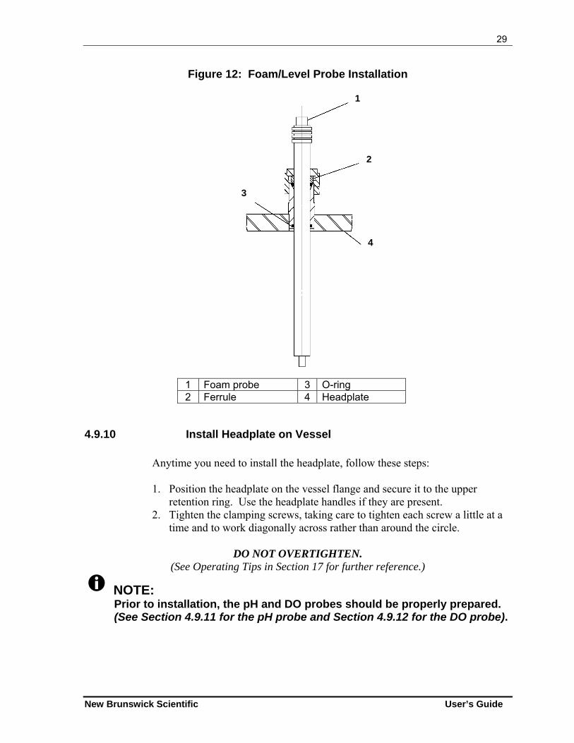
Figure 12: Foam/Level Probe Installation
1 Foam probe 3 O-ring 2 Ferrule 4 Headplate
4.9.10 Install Headplate on Vessel Anytime you need to install the headplate, follow these steps: 1. Position the headplate on the vessel flange and secure it to the upper
retention ring. Use the headplate handles if they are present. 2. Tighten the clamping screws, taking care to tighten each screw a little at a
time and to work diagonally across rather than around the circle.
DO NOT OVERTIGHTEN. (See Operating Tips in Section 17 for further reference.)
NOTE: Prior to installation, the pH and DO probes should be properly prepared. (See Section 4.9.11 for the pH probe and Section 4.9.12 for the DO probe).
FERRULE
O-RING
1
2
3
4
30
BioFlo 310 M1287-0054 User’s Guide
4.9.11 Install pH Probe
1. Wear protective gloves to protect yourself in case of accidental breakage. 2. Lightly coat the pH probe with glycerol or DI water to reduce friction. 3. Gently insert the probe into the appropriate port (see Figures 5, 6a, 6b & 7
above). The fit may be snug; gently turn the probe as you press it into the port to avoid breakage.
4.9.12 Install DO Probe
1. Wear protective gloves to protect yourself in case of accidental breakage. 2. Lightly coat the DO probe with glycerol or DI water to reduce friction. 3. Gently insert the probe into its adapter. 4. Gently insert the probe & adaptor into the appropriate port (see Figures 5,
6a, 6b & 7 above for reference). The fit may be snug; gently turn the probe as you press it into the port to avoid breakage.
NOTE: To avoid damage to the probes during operation, be sure that there is no interference between the probes and the baffle assembly, or between the probes and the impeller blades. We recommend installation of the probes at the vertical opening of the baffle.
4.9.13 Install Vessel
Position the vessel next to the control cabinet, in the rounded cut-out designed for vessel placement between pumps and connectors. Be sure to keep the water line quick-connects to the left. (See Figure 2 for reference.)
4.9.14 Install Motor Assembly
1. Position the motor assembly on top of the bearing housing, using the locating pin (or locating slot, if applicable) to orient it properly.
2. Connect the motor cable to the receptacle on the face of the control cabinet.
31
New Brunswick Scientific User’s Guide
4.9.15 Make All Connections
1. Connect cables from all probes to their respective sockets on the face of the control cabinet (see Figure 1a).
2. Connect the ground lead from the antifoam socket on the face of the control cabinet to the pin in the headplate (see Figures 5, 6a, 6b & 7 above for reference).
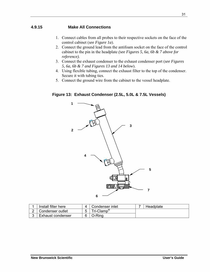
3. Connect the exhaust condenser to the exhaust condenser port (see Figures 5, 6a, 6b & 7 and Figures 13 and 14 below).
4. Using flexible tubing, connect the exhaust filter to the top of the condenser. Secure it with tubing ties.
5. Connect the ground wire from the cabinet to the vessel headplate.
Figure 13: Exhaust Condenser (2.5L, 5.0L & 7.5L Vessels)
1 Install filter here 4 Condenser inlet 7 Headplate 2 Condenser outlet 5 Tri-Clamp® 3 Exhaust condenser 6 O-Ring
3
7
6
1
5
2
4
32
BioFlo 310 M1287-0054 User’s Guide
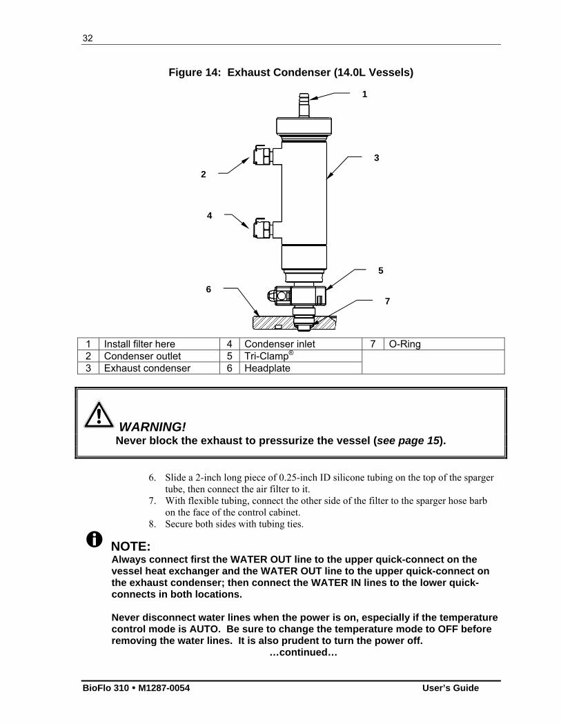
Figure 14: Exhaust Condenser (14.0L Vessels)
1 Install filter here 4 Condenser inlet 7 O-Ring 2 Condenser outlet 5 Tri-Clamp® 3 Exhaust condenser 6 Headplate
WARNING! Never block the exhaust to pressurize the vessel (see page 15).
6. Slide a 2-inch long piece of 0.25-inch ID silicone tubing on the top of the sparger
tube, then connect the air filter to it. 7. With flexible tubing, connect the other side of the filter to the sparger hose barb
on the face of the control cabinet. 8. Secure both sides with tubing ties.
NOTE: Always connect first the WATER OUT line to the upper quick-connect on the vessel heat exchanger and the WATER OUT line to the upper quick-connect on the exhaust condenser; then connect the WATER IN lines to the lower quick-connects in both locations.
Never disconnect water lines when the power is on, especially if the temperature control mode is AUTO. Be sure to change the temperature mode to OFF before removing the water lines. It is also prudent to turn the power off.
…continued…
1
3
6 7
5
2
4
33
New Brunswick Scientific User’s Guide
When you do remove the water lines, disconnect the WATER IN line first, to protect yourself from water spraying from the heat exchanger or exhaust condenser.
Prime water lines before first use and every time the vessel has been disconnected (see Section 4.9).
4.10 Main Power Switch
The main power switch is located on the righthand side of the control cabinet, below the touchscreen and above Pumps 1-3.
CAUTION! Before turning on the main power switch, make sure that: (1) The input water hose is connected, the drain line is connected and the water supply is turned on; (2) The vessel is in place and the quick-connect water lines are connected to the vessel’s heat exchanger; (3) The power cord is properly connected to the control cabinet and plugged into a suitable power outlet. Failure to observe these cautions may lead to premature pump failure.
4.11 Optional BioCommand Software
If you are using NBS supervisory software, be sure to consult your BioCommand user’s manual for installation and start-up instructions in addition to the general instructions provided below.
A 25-pin RS232/422 Modbus com port is provided on the rear panel of the control cabinet (see Figure 33 in Section 6.3) to connect the BioFlo 310 to a supervisory host computer. Communications to BioCommand software are via an optional RS-232 interface cable:
1. Connect the 25-pin end of the RS-232 cable to the AFS/Modbus port, and ensure that the connection is secure.
2. Hand tighten the thumbscrews. 3. Refer to the BioCommand user’s guide for instructions on connecting the RS-232
interface cable to the supervisory host computer.
4.12 Inputs/Outputs for Ancillary Devices
Each thermal mass flow controller (TMFC) uses one 0-5V analog input and one 0-5V analog output port. There is also an analog input/output port reserved (and labeled) for the Gas Overlay option available for cell culture.
34
BioFlo 310 M1287-0054 User’s Guide
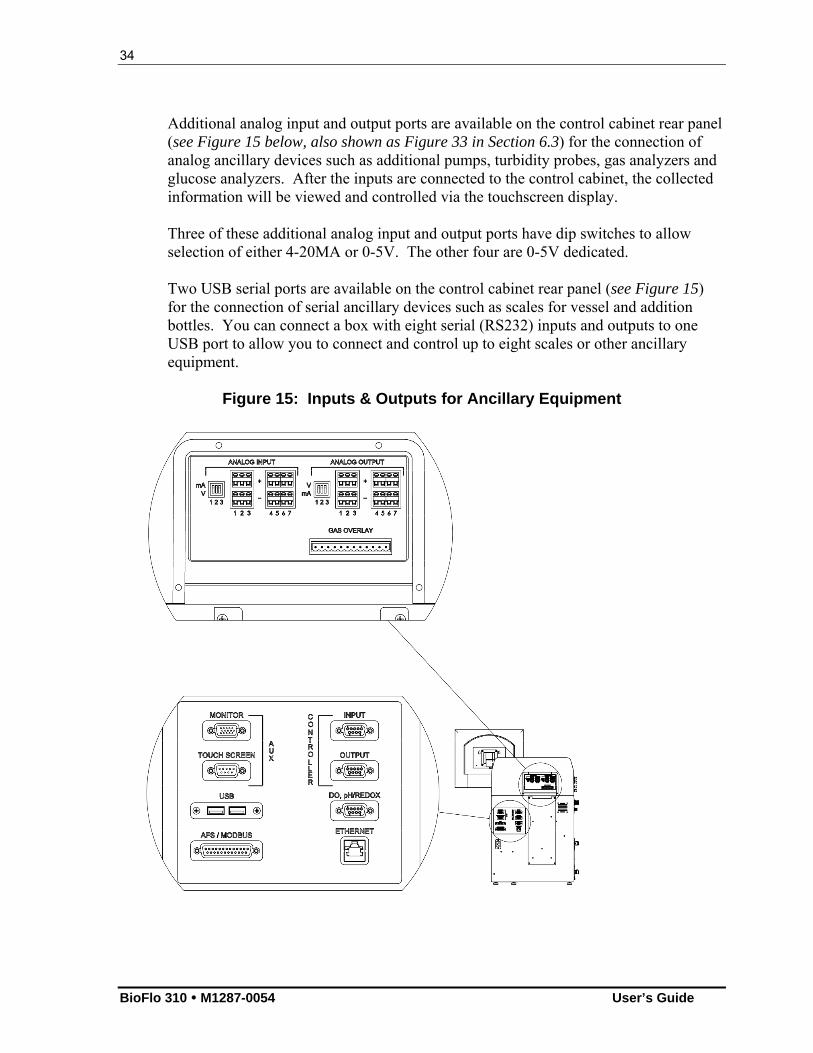
Additional analog input and output ports are available on the control cabinet rear panel (see Figure 15 below, also shown as Figure 33 in Section 6.3) for the connection of analog ancillary devices such as additional pumps, turbidity probes, gas analyzers and glucose analyzers. After the inputs are connected to the control cabinet, the collected information will be viewed and controlled via the touchscreen display. Three of these additional analog input and output ports have dip switches to allow selection of either 4-20MA or 0-5V. The other four are 0-5V dedicated. Two USB serial ports are available on the control cabinet rear panel (see Figure 15) for the connection of serial ancillary devices such as scales for vessel and addition bottles. You can connect a box with eight serial (RS232) inputs and outputs to one USB port to allow you to connect and control up to eight scales or other ancillary equipment.
Figure 15: Inputs & Outputs for Ancillary Equipment
35
New Brunswick Scientific User’s Guide
55 SSPPEECCIIFFIICCAATTIIOONNSS
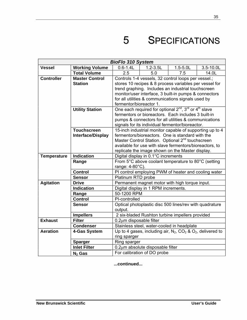
BioFlo 310 System Working Volume 0.6-1.4L 1.2-3.5L 1.5-5.0L 3.5-10.0L Vessel Total Volume 2.5 5.0 7.5 14.0L Master Control Station
Controls 1-4 vessels, 32 control loops per vessel.; stores 10 recipes & 8 process variables per vessel for trend graphing. Includes an industrial touchscreen monitor/user interface, 3 built-in pumps & connectors for all utilities & communications signals used by fermentor/bioreactor 1.
Utility Station One each required for optional 2nd, 3rd or 4th slave fermentors or bioreactors. Each includes 3 built-in pumps & connectors for all utilities & communications signals for its individual fermentor/bioreactor.
Controller
Touchscreen Interface/Display
15-inch industrial monitor capable of supporting up to 4 fermentors/bioreactors. One is standard with the Master Control Station. Optional 2nd touchscreen available for use with slave fermentors/bioreactors, to replicate the image shown on the Master display.
Indication Digital display in 0.1°C increments Range From 5°C above coolant temperature to 80°C (setting
range: 4-80°C). Control PI control employing PWM of heater and cooling water
Temperature
Sensor Platinum RTD probe Drive Permanent magnet motor with high torque input. Indication Digital display in 1 RPM increments. Range 50-1200 RPM Control PI-controlled Sensor Optical photoplastic disc 500 lines/rev with quadrature
output.
Agitation
Impellers 2 six-bladed Rushton turbine impellers provided Filter 0.2μm disposable filter Exhaust Condenser Stainless steel, water-cooled in headplate 4-Gas System Up to 4 gases, including air, N2, CO2 & O2, delivered to
ring sparger Sparger Ring sparger Inlet Filter 0.2μm absolute disposable filter
Aeration
N2 Gas For calibration of DO probe
...continued...
36
BioFlo 310 M1287-0054 User’s Guide
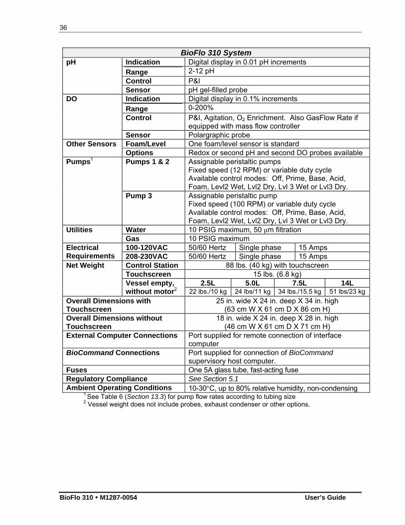
BioFlo 310 System Indication Digital display in 0.01 pH increments Range 2-12 pH Control P&I
pH
Sensor pH gel-filled probe Indication Digital display in 0.1% increments Range 0-200% Control P&I, Agitation, O2 Enrichment. Also GasFlow Rate if
equipped with mass flow controller
DO
Sensor Polargraphic probe Foam/Level One foam/level sensor is standard Other Sensors Options Redox or second pH and second DO probes available Pumps 1 & 2 Assignable peristaltic pumps
Fixed speed (12 RPM) or variable duty cycle Available control modes: Off, Prime, Base, Acid, Foam, Levl2 Wet, Lvl2 Dry, Lvl 3 Wet or Lvl3 Dry.
Pumps1
Pump 3 Assignable peristaltic pump Fixed speed (100 RPM) or variable duty cycle Available control modes: Off, Prime, Base, Acid, Foam, Levl2 Wet, Lvl2 Dry, Lvl 3 Wet or Lvl3 Dry.
Water 10 PSIG maximum, 50 μm filtration Utilities Gas 10 PSIG maximum 100-120VAC 50/60 Hertz Single phase 15 Amps Electrical
Requirements 208-230VAC 50/60 Hertz Single phase 15 Amps Net Weight Control Station 88 lbs. (40 kg) with touchscreen Touchscreen 15 lbs. (6.8 kg) 2.5L 5.0L 7.5L 14L
Vessel empty, without motor2 22 lbs./10 kg 24 lbs/11 kg 34 lbs./15.5 kg 51 lbs/23 kg
Overall Dimensions with Touchscreen
25 in. wide X 24 in. deep X 34 in. high (63 cm W X 61 cm D X 86 cm H)
Overall Dimensions without Touchscreen
18 in. wide X 24 in. deep X 28 in. high (46 cm W X 61 cm D X 71 cm H)
External Computer Connections Port supplied for remote connection of interface computer
BioCommand Connections Port supplied for connection of BioCommand supervisory host computer.
Fuses One 5A glass tube, fast-acting fuse Regulatory Compliance See Section 5.1 Ambient Operating Conditions 10-30C, up to 80% relative humidity, non-condensing
1 See Table 6 (Section 13.3) for pump flow rates according to tubing size 2 Vessel weight does not include probes, exhaust condenser or other options.

37
New Brunswick Scientific User’s Guide
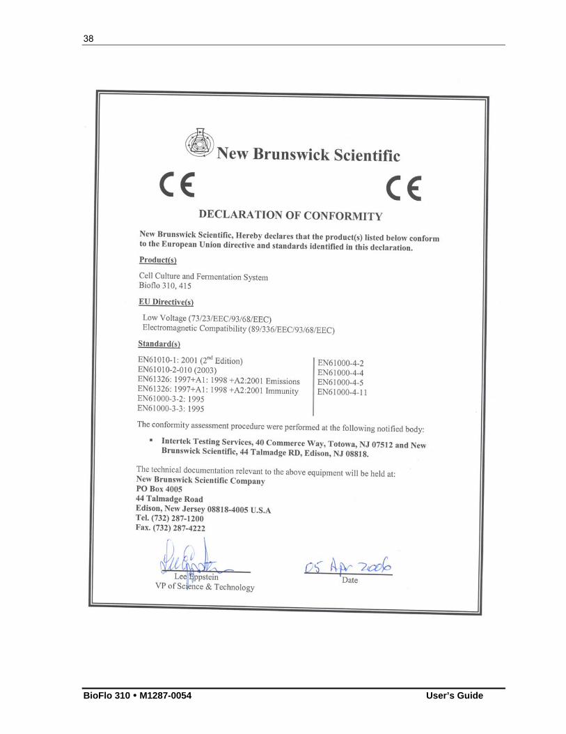
5.1 Certifications
The BioFlo 310 has been tested to ETL standards, to comply with all appropriate safety standards. As attested in the CE Declaration of Conformity reproduced on the following page, they also conform to the appropriate CE standards.
38
BioFlo 310 M1287-0054 User’s Guide
39
New Brunswick Scientific User’s Guide
66 OOPPEERRAATTIINNGG CCOONNTTRROOLLSS
6.1 Touchscreen
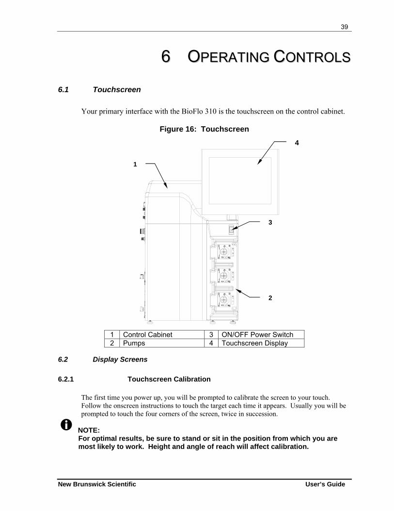
Your primary interface with the BioFlo 310 is the touchscreen on the control cabinet.
Figure 16: Touchscreen
1 Control Cabinet 3 ON/OFF Power Switch 2 Pumps 4 Touchscreen Display
6.2 Display Screens
6.2.1 Touchscreen Calibration
The first time you power up, you will be prompted to calibrate the screen to your touch. Follow the onscreen instructions to touch the target each time it appears. Usually you will be prompted to touch the four corners of the screen, twice in succession.
NOTE: For optimal results, be sure to stand or sit in the position from which you are most likely to work. Height and angle of reach will affect calibration.
1
4
3
2
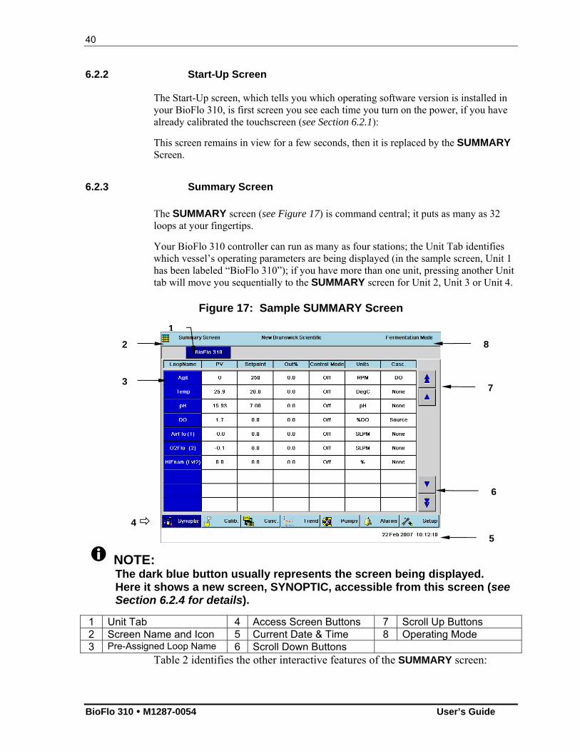
40
BioFlo 310 M1287-0054 User’s Guide
6.2.2 Start-Up Screen
The Start-Up screen, which tells you which operating software version is installed in your BioFlo 310, is first screen you see each time you turn on the power, if you have already calibrated the touchscreen (see Section 6.2.1):
This screen remains in view for a few seconds, then it is replaced by the SUMMARY Screen.
6.2.3 Summary Screen
The SUMMARY screen (see Figure 17) is command central; it puts as many as 32 loops at your fingertips.
Your BioFlo 310 controller can run as many as four stations; the Unit Tab identifies which vessel’s operating parameters are being displayed (in the sample screen, Unit 1 has been labeled “BioFlo 310”); if you have more than one unit, pressing another Unit tab will move you sequentially to the SUMMARY screen for Unit 2, Unit 3 or Unit 4.
Figure 17: Sample SUMMARY Screen
NOTE: The dark blue button usually represents the screen being displayed. Here it shows a new screen, SYNOPTIC, accessible from this screen (see Section 6.2.4 for details).
1 Unit Tab 4 Access Screen Buttons 7 Scroll Up Buttons 2 Screen Name and Icon 5 Current Date & Time 8 Operating Mode 3 Pre-Assigned Loop Name 6 Scroll Down Buttons
Table 2 identifies the other interactive features of the SUMMARY screen:
4
6
7
5
2
3
8
1
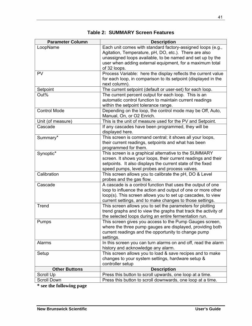
41
New Brunswick Scientific User’s Guide
Table 2: SUMMARY Screen Features
Parameter Column Description LoopName Each unit comes with standard factory-assigned loops (e.g.,
Agitation, Temperature, pH, DO, etc.). There are also unassigned loops available, to be named and set up by the user when adding external equipment, for a maximum total of 32 loops.
PV Process Variable: here the display reflects the current value for each loop, in comparison to its setpoint (displayed in the next column).
Setpoint The current setpoint (default or user-set) for each loop. Out% The current percent output for each loop. This is an
automatic control function to maintain current readings within the setpoint tolerance range.
Control Mode Depending on the loop, the control mode may be Off, Auto, Manual, On, or O2 Enrich.
Unit (of measure) This is the unit of measure used for the PV and Setpoint. Cascade If any cascades have been programmed, they will be
displayed here. Summary* This screen is command central; it shows all your loops,
their current readings, setpoints and what has been programmed for them.
Synoptic* This screen is a graphical alternative to the SUMMARY screen. It shows your loops, their current readings and their setpoints. It also displays the current state of the fixed speed pumps, level probes and process valves.
Calibration This screen allows you to calibrate the pH, DO & Level probes and the gas flow.
Cascade A cascade is a control function that uses the output of one loop to influence the action and output of one or more other loop(s). This screen allows you to set up cascades, to view current settings, and to make changes to those settings.
Trend This screen allows you to set the parameters for plotting trend graphs and to view the graphs that track the activity of the selected loops during an entire fermentation run.
Pumps This screen gives you access to the Pump Gauges screen, where the three pump gauges are displayed, providing both current readings and the opportunity to change pump settings.
Alarms In this screen you can turn alarms on and off, read the alarm history and acknowledge any alarm.
Setup This screen allows you to load & save recipes and to make changes to your system settings, hardware setup & controller setup
Other Buttons Description Scroll Up Press this button to scroll upwards, one loop at a time. Scroll Down Press this button to scroll downwards, one loop at a time. * see the following page
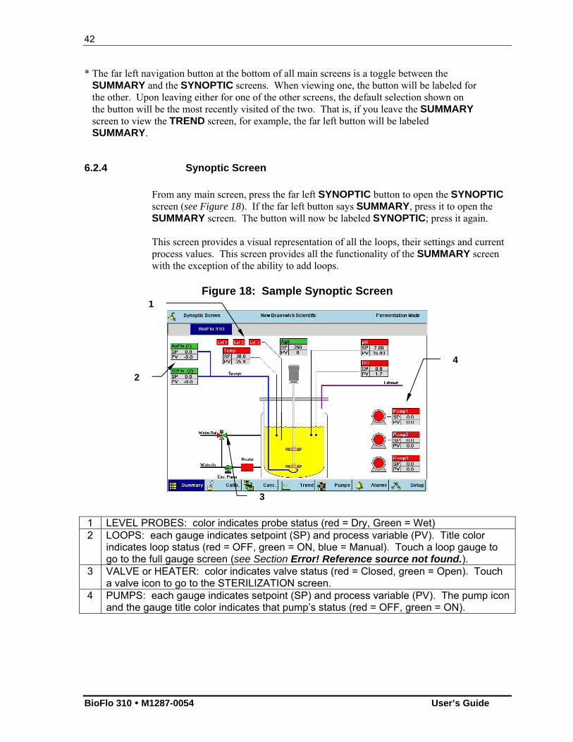
42
BioFlo 310 M1287-0054 User’s Guide
* The far left navigation button at the bottom of all main screens is a toggle between the SUMMARY and the SYNOPTIC screens. When viewing one, the button will be labeled for the other. Upon leaving either for one of the other screens, the default selection shown on the button will be the most recently visited of the two. That is, if you leave the SUMMARY screen to view the TREND screen, for example, the far left button will be labeled SUMMARY.
6.2.4 Synoptic Screen
From any main screen, press the far left SYNOPTIC button to open the SYNOPTIC screen (see Figure 18). If the far left button says SUMMARY, press it to open the SUMMARY screen. The button will now be labeled SYNOPTIC; press it again. This screen provides a visual representation of all the loops, their settings and current process values. This screen provides all the functionality of the SUMMARY screen with the exception of the ability to add loops.
Figure 18: Sample Synoptic Screen
1 LEVEL PROBES: color indicates probe status (red = Dry, Green = Wet) 2 LOOPS: each gauge indicates setpoint (SP) and process variable (PV). Title color
indicates loop status (red = OFF, green = ON, blue = Manual). Touch a loop gauge to go to the full gauge screen (see Section Error! Reference source not found.).
3 VALVE or HEATER: color indicates valve status (red = Closed, green = Open). Touch a valve icon to go to the STERILIZATION screen.
4 PUMPS: each gauge indicates setpoint (SP) and process variable (PV). The pump icon and the gauge title color indicates that pump’s status (red = OFF, green = ON).
4
3
1
2
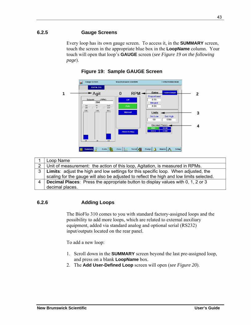
43
New Brunswick Scientific User’s Guide
6.2.5 Gauge Screens
Every loop has its own gauge screen. To access it, in the SUMMARY screen, touch the screen in the appropriate blue box in the LoopName column. Your touch will open that loop’s GAUGE screen (see Figure 19 on the following page).
Figure 19: Sample GAUGE Screen
1 Loop Name 2 Unit of measurement: the action of this loop, Agitation, is measured in RPMs. 3 Limits: adjust the high and low settings for this specific loop. When adjusted, the
scaling for the gauge will also be adjusted to reflect the high and low limits selected. 4 Decimal Places: Press the appropriate button to display values with 0, 1, 2 or 3
decimal places.
6.2.6 Adding Loops
The BioFlo 310 comes to you with standard factory-assigned loops and the possibility to add more loops, which are related to external auxiliary equipment, added via standard analog and optional serial (RS232) input/outputs located on the rear panel.
To add a new loop: 1. Scroll down in the SUMMARY screen beyond the last pre-assigned loop,
and press on a blank LoopName box. 2. The Add User-Defined Loop screen will open (see Figure 20).
1 2
4
3
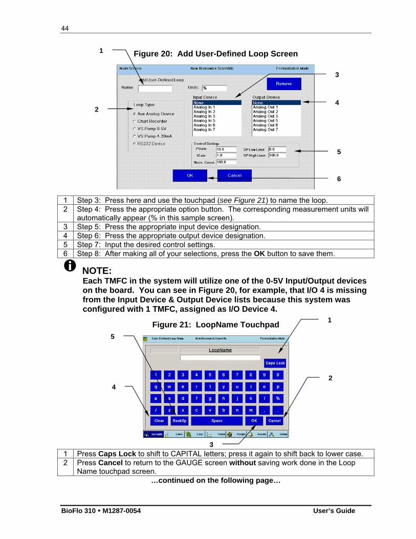
44
BioFlo 310 M1287-0054 User’s Guide
Figure 20: Add User-Defined Loop Screen
1 Step 3: Press here and use the touchpad (see Figure 21) to name the loop. 2 Step 4: Press the appropriate option button. The corresponding measurement units will
automatically appear (% in this sample screen). 3 Step 5: Press the appropriate input device designation. 4 Step 6: Press the appropriate output device designation. 5 Step 7: Input the desired control settings. 6 Step 8: After making all of your selections, press the OK button to save them.
NOTE: Each TMFC in the system will utilize one of the 0-5V Input/Output devices on the board. You can see in Figure 20, for example, that I/O 4 is missing from the Input Device & Output Device lists because this system was configured with 1 TMFC, assigned as I/O Device 4.
Figure 21: LoopName Touchpad
1 Press Caps Lock to shift to CAPITAL letters; press it again to shift back to lower case. 2 Press Cancel to return to the GAUGE screen without saving work done in the Loop
Name touchpad screen. …continued on the following page…
1
5
2
3
4
1
2
3
4
5
6
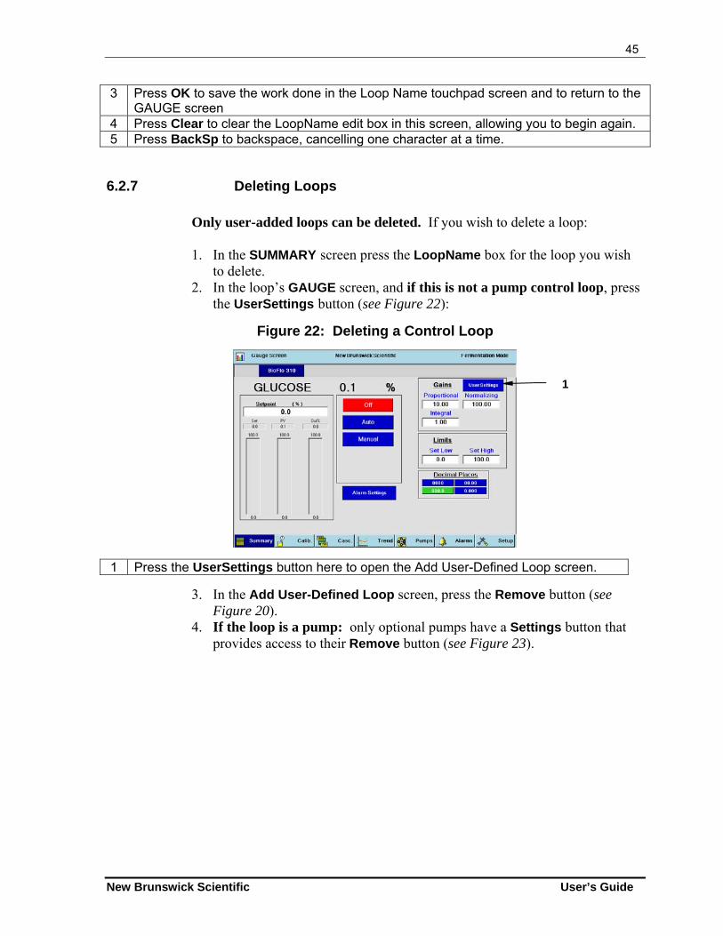
45
New Brunswick Scientific User’s Guide
3 Press OK to save the work done in the Loop Name touchpad screen and to return to the GAUGE screen
4 Press Clear to clear the LoopName edit box in this screen, allowing you to begin again. 5 Press BackSp to backspace, cancelling one character at a time.
6.2.7 Deleting Loops
Only user-added loops can be deleted. If you wish to delete a loop: 1. In the SUMMARY screen press the LoopName box for the loop you wish
to delete. 2. In the loop’s GAUGE screen, and if this is not a pump control loop, press
the UserSettings button (see Figure 22):
Figure 22: Deleting a Control Loop
1 Press the UserSettings button here to open the Add User-Defined Loop screen.
3. In the Add User-Defined Loop screen, press the Remove button (see Figure 20).
4. If the loop is a pump: only optional pumps have a Settings button that provides access to their Remove button (see Figure 23).
1
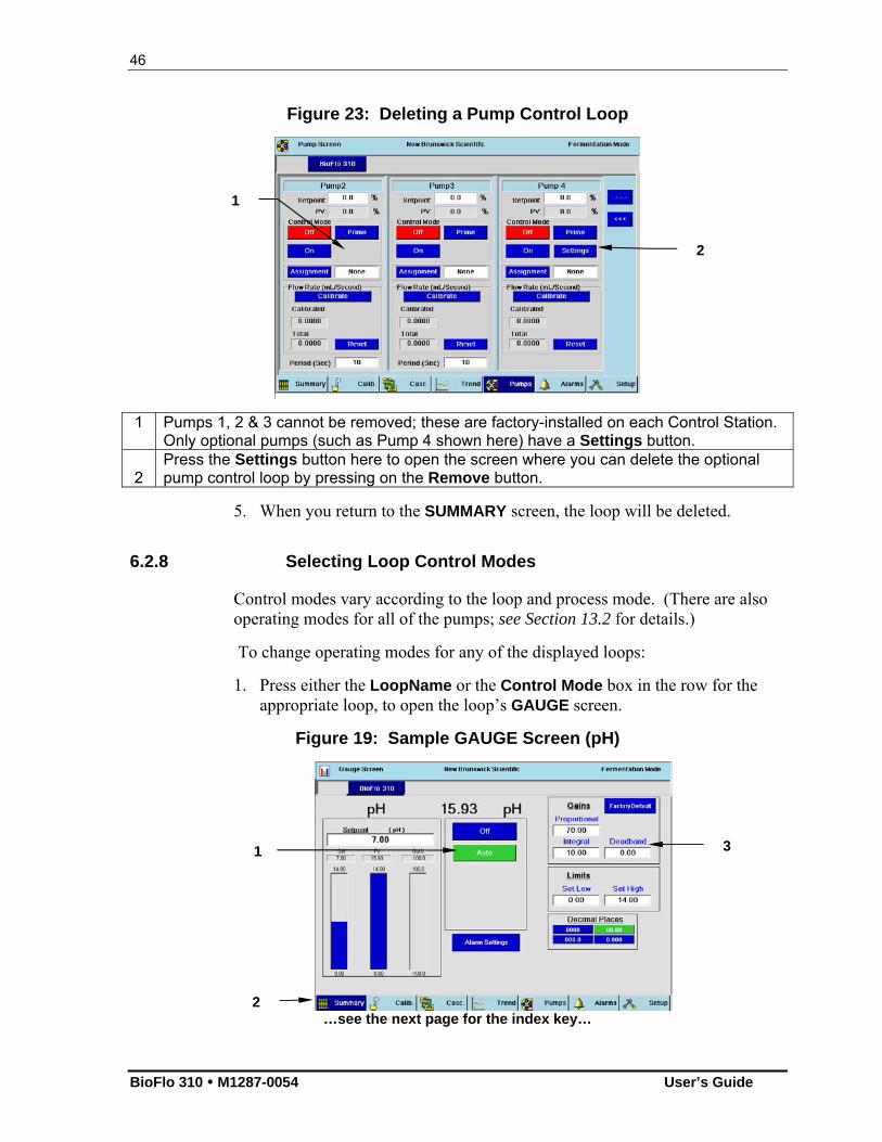
46
BioFlo 310 M1287-0054 User’s Guide
Figure 23: Deleting a Pump Control Loop
1 Pumps 1, 2 & 3 cannot be removed; these are factory-installed on each Control Station. Only optional pumps (such as Pump 4 shown here) have a Settings button.
2
Press the Settings button here to open the screen where you can delete the optional pump control loop by pressing on the Remove button.
5. When you return to the SUMMARY screen, the loop will be deleted.
6.2.8 Selecting Loop Control Modes
Control modes vary according to the loop and process mode. (There are also operating modes for all of the pumps; see Section 13.2 for details.)
To change operating modes for any of the displayed loops:
1. Press either the LoopName or the Control Mode box in the row for the appropriate loop, to open the loop’s GAUGE screen.
Figure 19: Sample GAUGE Screen (pH)
…see the next page for the index key…
2
1
1
2
3
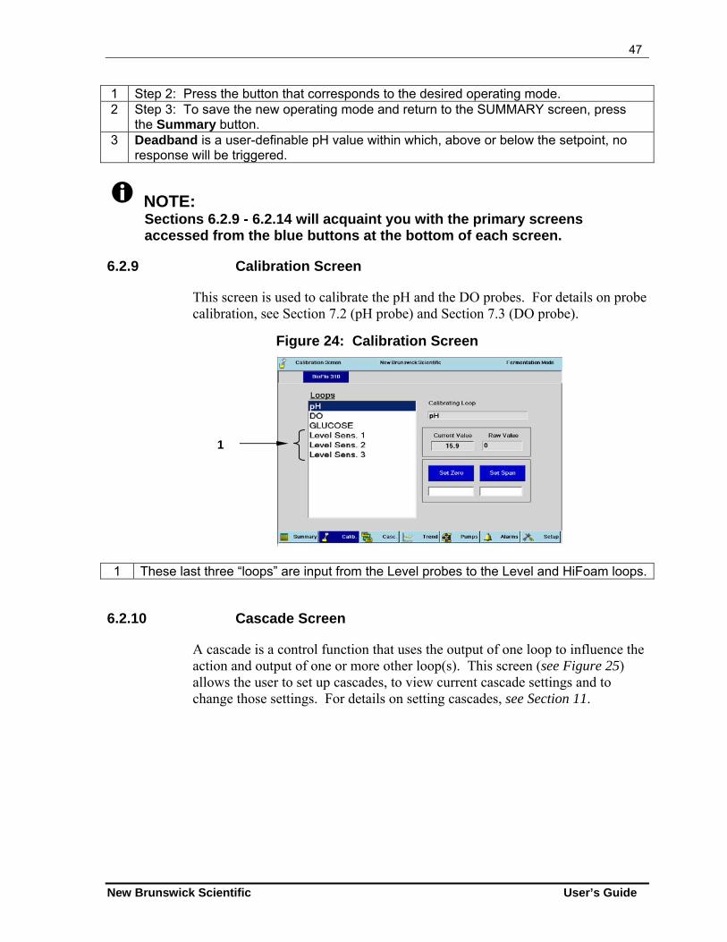
47
New Brunswick Scientific User’s Guide
1 Step 2: Press the button that corresponds to the desired operating mode. 2 Step 3: To save the new operating mode and return to the SUMMARY screen, press
the Summary button. 3 Deadband is a user-definable pH value within which, above or below the setpoint, no
response will be triggered.
NOTE: Sections 6.2.9 - 6.2.14 will acquaint you with the primary screens accessed from the blue buttons at the bottom of each screen.
6.2.9 Calibration Screen
This screen is used to calibrate the pH and the DO probes. For details on probe calibration, see Section 7.2 (pH probe) and Section 7.3 (DO probe).
Figure 24: Calibration Screen
1 These last three “loops” are input from the Level probes to the Level and HiFoam loops.
6.2.10 Cascade Screen
A cascade is a control function that uses the output of one loop to influence the action and output of one or more other loop(s). This screen (see Figure 25) allows the user to set up cascades, to view current cascade settings and to change those settings. For details on setting cascades, see Section 11.
1
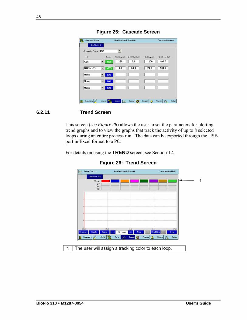
48
BioFlo 310 M1287-0054 User’s Guide
Figure 25: Cascade Screen
6.2.11 Trend Screen
This screen (see Figure 26) allows the user to set the parameters for plotting trend graphs and to view the graphs that track the activity of up to 8 selected loops during an entire process run. The data can be exported through the USB port in Excel format to a PC. For details on using the TREND screen, see Section 12.
Figure 26: Trend Screen
1 The user will assign a tracking color to each loop.
1

49
New Brunswick Scientific User’s Guide
6.2.12 Pumps Screen
This screen (see Figure 27) allows the user to access the pump gauges screens, where the three standard pumps (plus any optional pumps) are displayed, providing both current readings and the opportunity to change pump settings. For details on using the PUMPS screen, see Section 10.5.
Figure 27: Pumps Screen
6.2.13 Alarms Screen
This screen (see Figure 28) allows the user to turn alarms on and off, to read the alarm history and to acknowledge any alarm while it is active. For details on using the ALARMS screen, see Section 14.
Figure 28: Alarms Screen
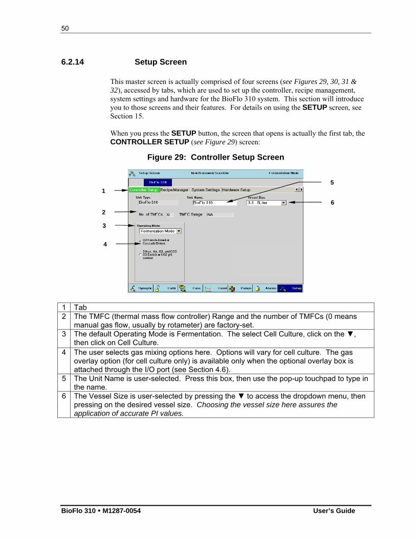
50
BioFlo 310 M1287-0054 User’s Guide
6.2.14 Setup Screen
This master screen is actually comprised of four screens (see Figures 29, 30, 31 & 32), accessed by tabs, which are used to set up the controller, recipe management, system settings and hardware for the BioFlo 310 system. This section will introduce you to those screens and their features. For details on using the SETUP screen, see Section 15. When you press the SETUP button, the screen that opens is actually the first tab, the CONTROLLER SETUP (see Figure 29) screen:
Figure 29: Controller Setup Screen
1 Tab 2 The TMFC (thermal mass flow controller) Range and the number of TMFCs (0 means
manual gas flow, usually by rotameter) are factory-set. 3 The default Operating Mode is Fermentation. The select Cell Culture, click on the ▼,
then click on Cell Culture. 4 The user selects gas mixing options here. Options will vary for cell culture. The gas
overlay option (for cell culture only) is available only when the optional overlay box is attached through the I/O port (see Section 4.6).
5 The Unit Name is user-selected. Press this box, then use the pop-up touchpad to type in the name.
6 The Vessel Size is user-selected by pressing the ▼ to access the dropdown menu, then pressing on the desired vessel size. Choosing the vessel size here assures the application of accurate PI values.
1 5
6
2
3
4
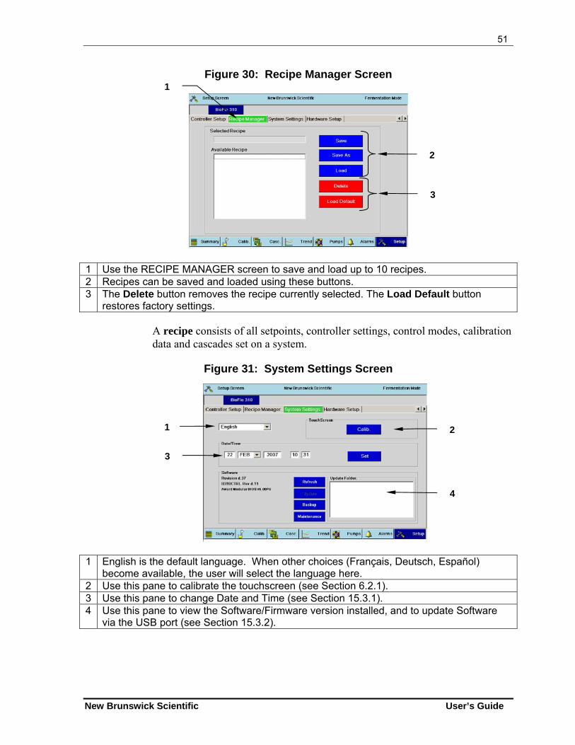
51
New Brunswick Scientific User’s Guide
Figure 30: Recipe Manager Screen
1 Use the RECIPE MANAGER screen to save and load up to 10 recipes. 2 Recipes can be saved and loaded using these buttons. 3 The Delete button removes the recipe currently selected. The Load Default button
restores factory settings.
A recipe consists of all setpoints, controller settings, control modes, calibration data and cascades set on a system.
Figure 31: System Settings Screen
1 English is the default language. When other choices (Français, Deutsch, Español) become available, the user will select the language here.
2 Use this pane to calibrate the touchscreen (see Section 6.2.1). 3 Use this pane to change Date and Time (see Section 15.3.1). 4 Use this pane to view the Software/Firmware version installed, and to update Software
via the USB port (see Section 15.3.2).
3
1 2
4
1
2
3
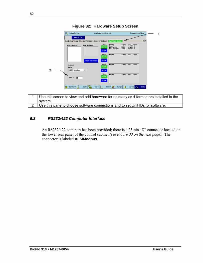
52
BioFlo 310 M1287-0054 User’s Guide
Figure 32: Hardware Setup Screen
1 Use this screen to view and add hardware for as many as 4 fermentors installed in the system.
2 Use this pane to choose software connections and to set Unit IDs for software.
6.3 RS232/422 Computer Interface
An RS232/422 com port has been provided; there is a 25-pin “D” connector located on the lower rear panel of the control cabinet (see Figure 33 on the next page). The connector is labeled AFS/Modbus.
1
2
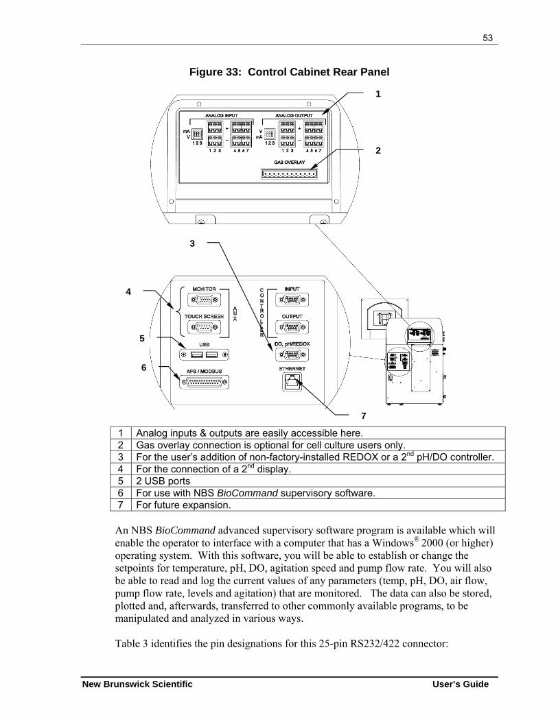
53
New Brunswick Scientific User’s Guide
Figure 33: Control Cabinet Rear Panel
1 Analog inputs & outputs are easily accessible here. 2 Gas overlay connection is optional for cell culture users only. 3 For the user’s addition of non-factory-installed REDOX or a 2nd pH/DO controller. 4 For the connection of a 2nd display. 5 2 USB ports 6 For use with NBS BioCommand supervisory software. 7 For future expansion.
An NBS BioCommand advanced supervisory software program is available which will enable the operator to interface with a computer that has a Windows® 2000 (or higher) operating system. With this software, you will be able to establish or change the setpoints for temperature, pH, DO, agitation speed and pump flow rate. You will also be able to read and log the current values of any parameters (temp, pH, DO, air flow, pump flow rate, levels and agitation) that are monitored. The data can also be stored, plotted and, afterwards, transferred to other commonly available programs, to be manipulated and analyzed in various ways.
Table 3 identifies the pin designations for this 25-pin RS232/422 connector:
1
2
3
7
4
5
6
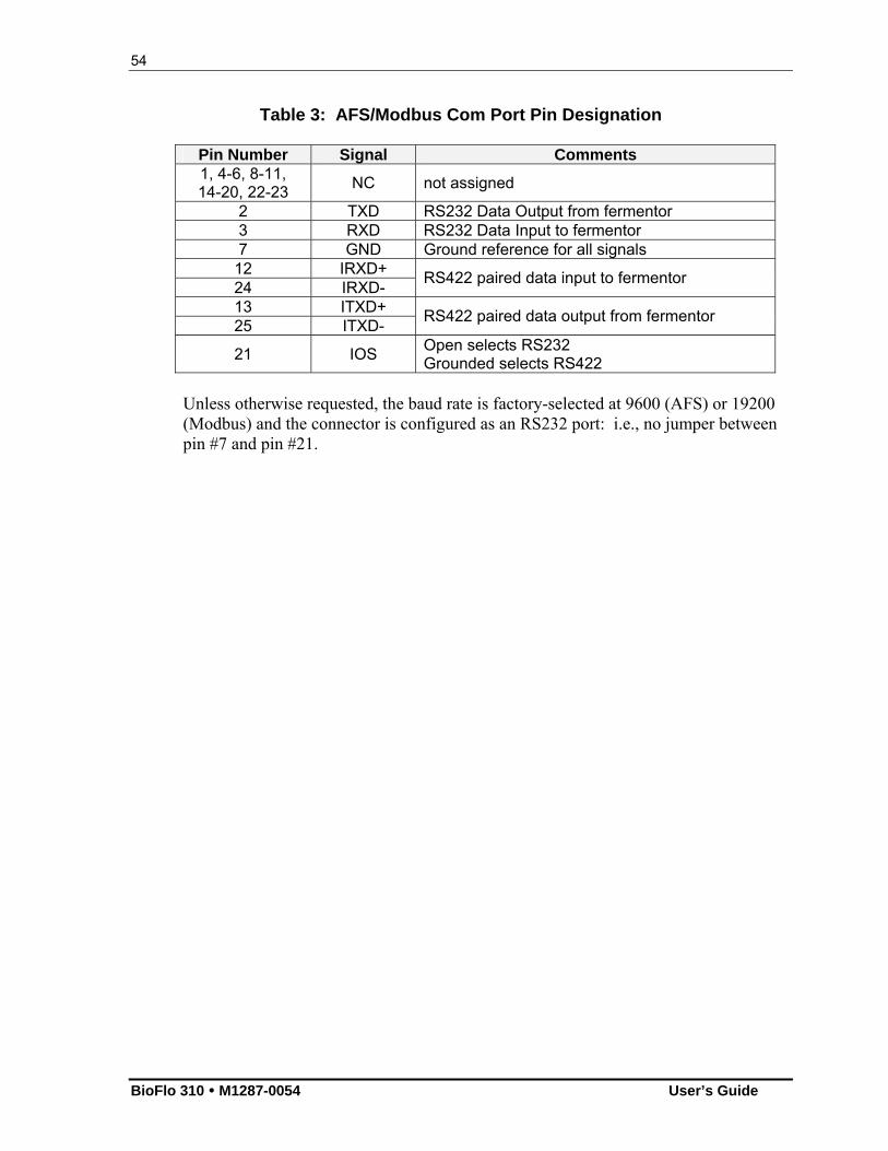
54
BioFlo 310 M1287-0054 User’s Guide
Table 3: AFS/Modbus Com Port Pin Designation
Pin Number Signal Comments 1, 4-6, 8-11, 14-20, 22-23
NC not assigned
2 TXD RS232 Data Output from fermentor 3 RXD RS232 Data Input to fermentor 7 GND Ground reference for all signals
12 IRXD+ 24 IRXD-
RS422 paired data input to fermentor
13 ITXD+ 25 ITXD-
RS422 paired data output from fermentor
21 IOS Open selects RS232 Grounded selects RS422
Unless otherwise requested, the baud rate is factory-selected at 9600 (AFS) or 19200 (Modbus) and the connector is configured as an RS232 port: i.e., no jumper between pin #7 and pin #21.
55
New Brunswick Scientific User’s Guide
77 PPRROOBBEE PPRREEPPAARRAATTIIOONN &&
CCAALLIIBBRRAATTIIOONN
7.1 pH Probe Inspection
Inspect probe for possible shipping damage. If damage is observed, notify the New Brunswick Scientific Service Department immediately. If you have a liquid-filled probe, check the level of the reference electrolyte. It should be about 1cm below the filling orifice. To add reference electrolyte, take the filling pipette (P0740-4820) and fill it with electrolyte solution. Check the electrode tip for trapped air bubbles. To remove any air bubbles, hold the electrode upright and shake gently. NEVER REST THE PROBE ON ITS TIP.
NOTE: Both chambers of the electrode are filled with the same reference electrolyte, for a total volume of approximately 30 mL. For normal operation, remove the rubber T stoppers if the probe is so equipped, saving them for use during sterilization.
7.2 pH Probe Calibration
NOTE: Calibrate the pH probe before autoclaving it with the vessel.
1. If you have not already done so, connect the pH probe to the pH connector on the control cabinet (see Figure 1a), using the appropriate cable.
2. Turn the main power switch ON. 3. Press the CALIBRATION button to display the CALIBRATION screen.
NOTE: The pH probe is calibrated using two external buffer solutions of known pH, usually 7.00 and 4.00.
4. Rinse the pH electrode with distilled water, then immerse it into pH 7.00 buffer solution and allow a few minutes for the system to equilibrate.
5. Open the CALIBRATION screen (see Figure 24, repeated below for easy reference).
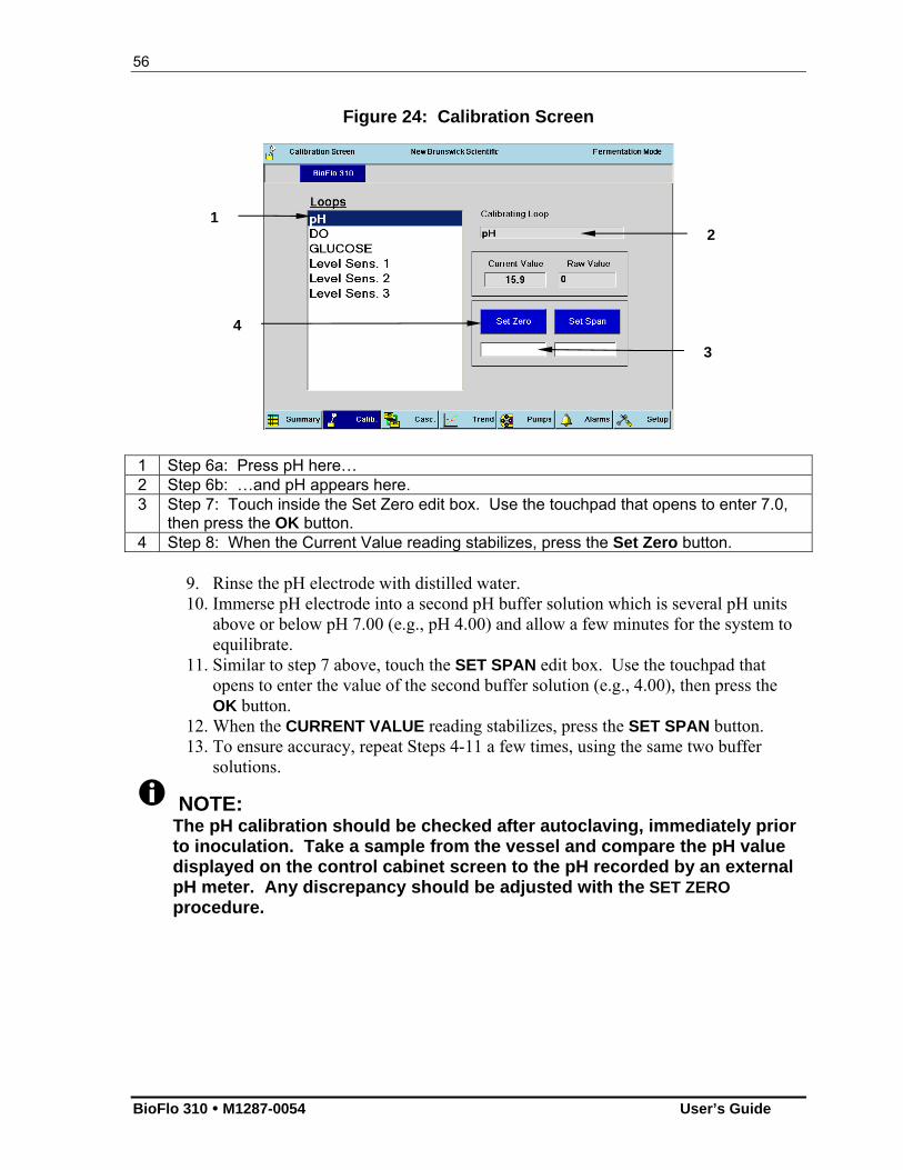
56
BioFlo 310 M1287-0054 User’s Guide
Figure 24: Calibration Screen
1 Step 6a: Press pH here… 2 Step 6b: …and pH appears here. 3 Step 7: Touch inside the Set Zero edit box. Use the touchpad that opens to enter 7.0,
then press the OK button. 4 Step 8: When the Current Value reading stabilizes, press the Set Zero button.
9. Rinse the pH electrode with distilled water. 10. Immerse pH electrode into a second pH buffer solution which is several pH units
above or below pH 7.00 (e.g., pH 4.00) and allow a few minutes for the system to equilibrate.
11. Similar to step 7 above, touch the SET SPAN edit box. Use the touchpad that opens to enter the value of the second buffer solution (e.g., 4.00), then press the OK button.
12. When the CURRENT VALUE reading stabilizes, press the SET SPAN button. 13. To ensure accuracy, repeat Steps 4-11 a few times, using the same two buffer
solutions.
NOTE: The pH calibration should be checked after autoclaving, immediately prior to inoculation. Take a sample from the vessel and compare the pH value displayed on the control cabinet screen to the pH recorded by an external pH meter. Any discrepancy should be adjusted with the SET ZERO procedure.
1 2
3
4
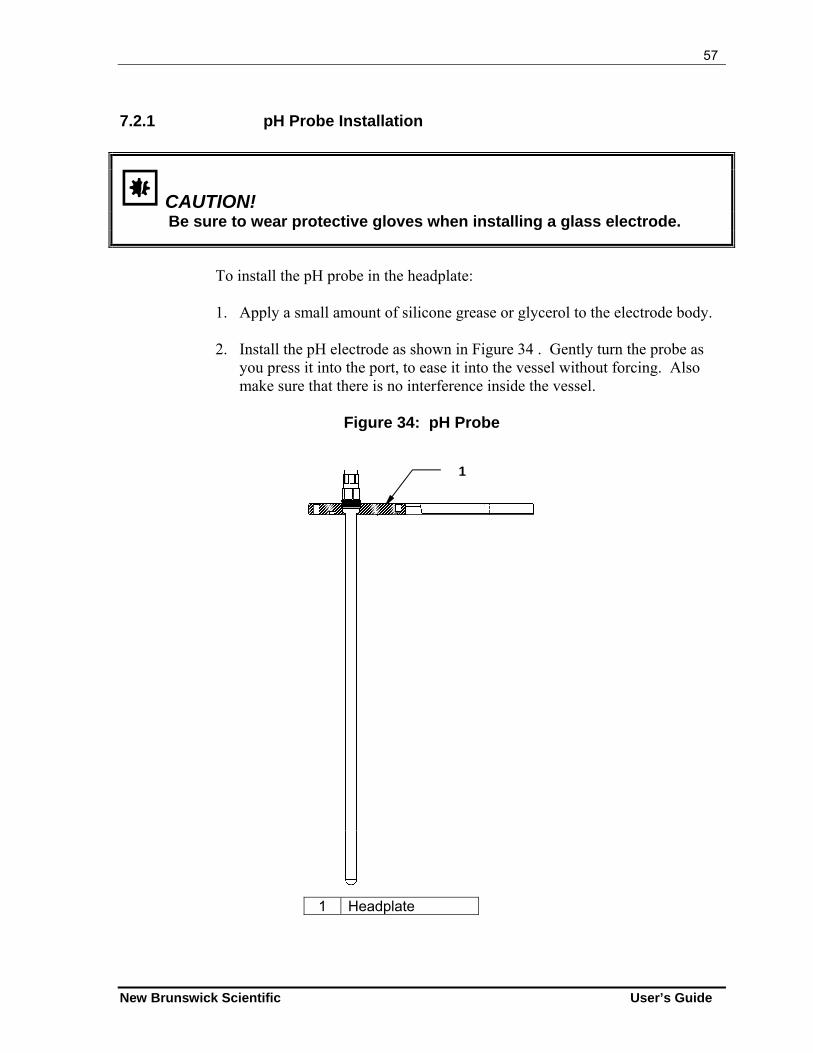
57
New Brunswick Scientific User’s Guide
7.2.1 pH Probe Installation
CAUTION! Be sure to wear protective gloves when installing a glass electrode.
To install the pH probe in the headplate:
1. Apply a small amount of silicone grease or glycerol to the electrode body.
2. Install the pH electrode as shown in Figure 34 . Gently turn the probe as
you press it into the port, to ease it into the vessel without forcing. Also make sure that there is no interference inside the vessel.
Figure 34: pH Probe
1 Headplate
1
58
BioFlo 310 M1287-0054 User’s Guide
CAUTION! We recommend that you avoid the use of hydrochloric acid (HCl) with the BioFlo 310 for pH control or any other purpose, because HCl corrodes stainless steel. Over time, it will severely damage the headplate, a costly component to replace, and other stainless steel components. Phosphoric and sulfuric (10% maximum concentration) acids are acceptable and are commonly used for pH control.
7.2.2 pH Probe Maintenance & Storage
If you have a liquid-filled probe, check the level of the filling solution. It should be about 1cm below the filling orifice.
Check for any trapped air bubbles in the electrode’s tip to remove bubbles, hold electrode upright and shake electrode gently.
The probe should be stored standing upright. The electrode tip should be immersed in the solution of 3 molar KCl or a buffer solution between pH 4.00 and pH 7.00. If the probe is so equipped, the two rubber T stoppers should be inserted.
CAUTION! Never let a pH probe rest on its tip, and never leave a pH probe in DI water.
7.3 Dissolved Oxygen (DO) Probe Preparation
7.3.1 Inspecting the DO Probe
Inspect the probe for possible shipping damage. Immediately report any damage you may observe to the New Brunswick Scientific Service Department. Remove the protective cap from the electrode end. The membrane is delicate and care must be exercised to prevent accidental damage. NEVER REST THE PROBE ON ITS MEMBRANE.
59
New Brunswick Scientific User’s Guide
7.3.2 DO Probe Preparation
To ensure stable output, the probe should be sent through two or three sterilization (autoclaving) cycles prior to use. The probe will be operable after the second cycle, but it will be more stable with additional sterilizations. The shorting plug should be installed on the probe during autoclaving or sterilization.
Default P & I (proportional & integral) gains are preset at the factory. They are different for each operating mode, fermentation and cell culture. It is strongly recommended that you maintain the factory-set parameters.
Nevertheless, P & I gains for the DO loop can be modified by the operator, using the touch pad on the front of the control cabinet. As noted above, fermentation mode and cell culture mode require different P & I values to ensure proper DO control. Whether you choose to use (as recommended) the factory-set values or to alter them, it is highly unlikely that you will ever need to re-set or change them. Even if the power fails during a run, the P & I values (pre-set if you do not change them, or your settings when you do) are stored in memory and should still be in effect when the power is restored. For details regarding P & I settings, see Section 22, Appendix B.
Nevertheless, it is always prudent to check these values at the beginning of a run, especially if the fermentor has not been used for a while or if other people have access to the unit.
NOTE: It is recommended that you use the factory-set P & I values. Do not attempt to change the settings unless you are experienced with P & I control.
7.3.3 DO Probe Installation
Install the DO probe into the vessel headplate assembly (see Figures 5-7 and Figure 35), ensuring that there is no interference inside the vessel and taking care to never strike or bump the tip of the probe. To install the probe without an adapter: 1. Unscrew the lock nut from the port. 2. Gently slide the lock nut onto the DO probe, from bottom to top. 3. Apply a light coat of glycerol to the sides of the probe. 4. Carefully insert the probe into the port, gently rotating it as you glide it into place. 5. When it is fully seated, finger tighten the lock nut.
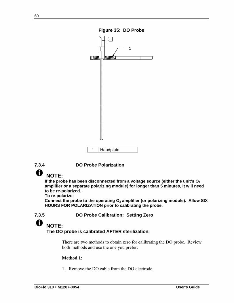
60
BioFlo 310 M1287-0054 User’s Guide
Figure 35: DO Probe
1 Headplate
7.3.4 DO Probe Polarization
NOTE: If the probe has been disconnected from a voltage source (either the unit’s O2 amplifier or a separate polarizing module) for longer than 5 minutes, it will need to be re-polarized. To re-polarize: Connect the probe to the operating O2 amplifier (or polarizing module). Allow SIX HOURS FOR POLARIZATION prior to calibrating the probe.
7.3.5 DO Probe Calibration: Setting Zero
NOTE: The DO probe is calibrated AFTER sterilization.
There are two methods to obtain zero for calibrating the DO probe. Review both methods and use the one you prefer: Method 1:
1. Remove the DO cable from the DO electrode.
1
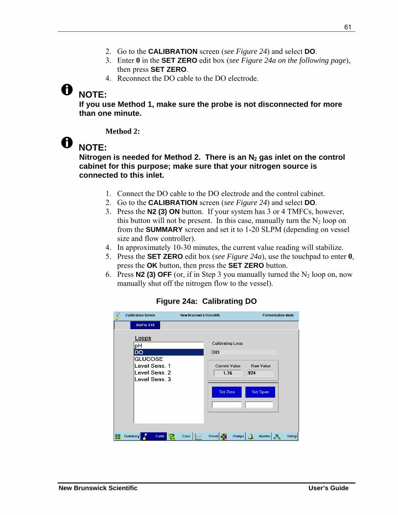
61
New Brunswick Scientific User’s Guide
2. Go to the CALIBRATION screen (see Figure 24) and select DO. 3. Enter 0 in the SET ZERO edit box (see Figure 24a on the following page),
then press SET ZERO. 4. Reconnect the DO cable to the DO electrode.
NOTE: If you use Method 1, make sure the probe is not disconnected for more than one minute.
Method 2:
NOTE: Nitrogen is needed for Method 2. There is an N2 gas inlet on the control cabinet for this purpose; make sure that your nitrogen source is connected to this inlet.
1. Connect the DO cable to the DO electrode and the control cabinet. 2. Go to the CALIBRATION screen (see Figure 24) and select DO. 3. Press the N2 (3) ON button. If your system has 3 or 4 TMFCs, however,
this button will not be present. In this case, manually turn the N2 loop on from the SUMMARY screen and set it to 1-20 SLPM (depending on vessel size and flow controller).
4. In approximately 10-30 minutes, the current value reading will stabilize. 5. Press the SET ZERO edit box (see Figure 24a), use the touchpad to enter 0,
press the OK button, then press the SET ZERO button. 6. Press N2 (3) OFF (or, if in Step 3 you manually turned the N2 loop on, now
manually shut off the nitrogen flow to the vessel).
Figure 24a: Calibrating DO
62
BioFlo 310 M1287-0054 User’s Guide
7.3.6 DO Probe Calibration: Setting Span
1. In the AGIT GAUGE screen, set the AGIT speed to 50 RPM. 2. Set the AGIT mode to AUTO. 3. Vigorously sparge air into the vessel via the filter on the headplate until the
display is stable for approximately 10 minutes (this may take up to 30 minutes total).
4. In the CALIBRATION screen, select DO. 5. Enter 100 in the SET SPAN edit box (see Figure 24a), then press the SET
SPAN button.
7.3.7 About Pump Calibration
To assure the most accurate flow rate, calibrate the pump each time you change tubing. See Section 10.6.4 for details.
63
New Brunswick Scientific User’s Guide
88 VVEESSSSEELL SSTTEERRIILLIIZZAATTIIOONN
NOTE: Before proceeding, consult the dimensions of your vessel assemblies to be sure your autoclave is large enough to accommodate the vessel with its various components.
WARNING! During autoclaving, the vessel exhaust filter and, if present, the water jacket drain must be vented to avoid explosion.
WARNING! Use protective gloves when handling hot components.
CAUTION! Before connecting or disconnecting the water hoses to/from the vessel at any time, be sure to follow these instructions in the order indicated: To connect: (1) Connect vessel Water Out line, (2) Connect vessel Water In line, (3) Connect cabinet Main Water In line, (4) Turn ON main power switch on cabinet. To disconnect: (1) Turn OFF main power switch on cabinet, (2) Disconnect Main Water In line from cabinet, (3) Disconnect vessel Water In line,
(4) Disconnect vessel Water Out line. Failure to heed these instructions may lead to hose leakage and/or pressure build-up inside the vessel jacket.
CAUTION! During sterilization: The bearing housing cap must be installed on the fermentation vessel bearing housing, to keep steam from damaging the internal bearings. On water-jacketed vessels, the jacket must be half-filled with water.
64
BioFlo 310 M1287-0054 User’s Guide
CAUTION! Never autoclave PVC tubing (clear with white braiding).
There are four objectives to preparing a vessel for sterilization:
A. To minimize pressure differences throughout the sterilization process by ensuring that the air can transfer freely between the inside and the outside of the vessel;
B. To ensure that minor pressure differences do not expel liquid from the vessel by clamping off all penetrations that go below liquid level;
C. To protect hydrophobic filters from blockage, which would occur if condensation were allowed to wet and block the filter surface;
D. To protect susceptible vessel assembly components from steam damage.
The first objective is met by leaving at least one vessel port open, the second by clamping shut flexible tubing attached to immersed penetrations, and the third by wrapping filters with a protective cap of aluminum foil. Use protective caps on probes and bearings to meet the fourth objective.
8.1 Initial Preparation for Autoclaving
If this is a water-jacketed vessel for Cell Culture, the jacket must be half-filled with water prior to autoclaving. Follow the steps in Section 8.1.1 below.
If this is a non-jacketed vessel, proceed to Section 8.2.
8.1.1 Filling the Water Jacket
To fill the water jacket on a Cell Culture vessel: 1. After the tubing and water supply are connected, make sure the solenoid
valve cable and the RTD cable are plugged into the Power Controller. 2. Set the temperature control mode to OFF. 3. Check that the temperature reading is higher than 5ºC. 4. Allow water to enter the piping system; it will stop at the solenoid valve. 5. Set the temperature loop control mode to AUTO. 6. Enter a temperature setpoint (SP) that is at least 12ºC below the process
variable (PV). The controller will respond to the call for cooling by opening the solenoid valve, filling the jacket with water.
7. When the jacket is halfway filled, set the temperature control mode to OFF.
65
New Brunswick Scientific User’s Guide
8.2 Additional Preparation for Autoclaving
To continue preparing the vessel for sterilization: 1. Turn off power to the controller. 2. Remove the motor from the top of the vessel and carefully put it aside. 3. Lubricate the vinyl bearing housing cap with silicone grease to facilitate sliding the
cap securely onto the housing. 4. Place the bearing housing cap on the top of the bearing housing. 5. Disconnect the air and/or gas lines from the inlet filter on the sparger. 6. Disconnect the water lines. Remove all PVC tubing. 7. Clamp off the harvest tube, the sample tube and all other penetrations that are
immersed in the media. 8. Remove the RTD from the thermowell. 9. Disconnect all probes and sensors, and remove their cables. 10. If you are using pH and DO probes, install each probe’s shorting cap (provided in
the probe kit). 11. Before placing the vessel into the autoclave, loosen the glass sample bottle by ½
turn. 12. Wrap all filters with aluminum foil to protect them from steam. 13. Attach a piece of tubing, wrapped with some non-absorbent material (such as glass
wool or non-absorbent cotton) to each of the addition ports. Wrap foil around the end of the tubing, shaped like a funnel, to allow the vessel to vent more easily during autoclaving. Place a clamp on the tubing.
NOTE: Be sure to leave one clamp open during autoclaving to equalize pressure. If this is a water-jacketed vessel, also leave the jacket water inlet clamp open.
If you have addition, foam trap or harvest bottles mounted at the base of the vessel, you can autoclave them with the vessel. Without detaching their tubing from the headplate: 14. Remove the bottle holder(s) and reinstall each on one of the headplate clamping
screws. 15. Reinsert the bottle and turn the holder until the bottle and holder are positioned
over the headplate, rather than extended over the edge. 16. Finger tighten the knurled nut. 17. Clamp off the tubing, and, where appropriate, remove it from the pump.
Probe tips must be moist during sterilization:
If you will be doing batch fermentation, be sure the vessel is filled with media so
the media will also be sterilized.
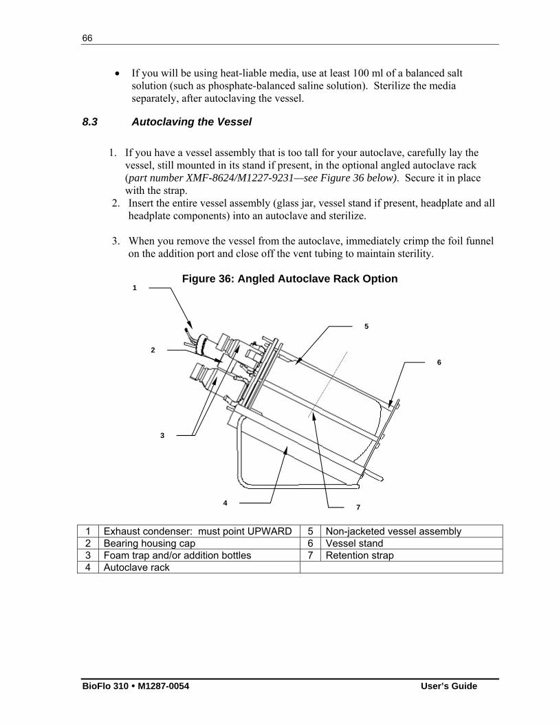
66
BioFlo 310 M1287-0054 User’s Guide
If you will be using heat-liable media, use at least 100 ml of a balanced salt solution (such as phosphate-balanced saline solution). Sterilize the media separately, after autoclaving the vessel.
8.3 Autoclaving the Vessel
1. If you have a vessel assembly that is too tall for your autoclave, carefully lay the
vessel, still mounted in its stand if present, in the optional angled autoclave rack (part number XMF-8624/M1227-9231—see Figure 36 below). Secure it in place with the strap.
2. Insert the entire vessel assembly (glass jar, vessel stand if present, headplate and all headplate components) into an autoclave and sterilize.
3. When you remove the vessel from the autoclave, immediately crimp the foil funnel
on the addition port and close off the vent tubing to maintain sterility.
Figure 36: Angled Autoclave Rack Option
1 Exhaust condenser: must point UPWARD 5 Non-jacketed vessel assembly 2 Bearing housing cap 6 Vessel stand 3 Foam trap and/or addition bottles 7 Retention strap 4 Autoclave rack
1
3
2
4
5
6
7
67
New Brunswick Scientific User’s Guide
8.3.1 Sterilization Time and Temperature
Sterilization time varies with autoclave characteristics, temperature settings, vessel size and contents (i.e., media properties). As a starting point, autoclave for 25 minutes after the autoclave reaches 121° C.
CAUTION! During autoclaving, the vessel and the water jacket (if present) must be vented at all times. Release the autoclave pressure only when the temperature has dropped below 90° C. Use slow exhaust (30-60 minutes). If available, the autoclave should be on liquid cycle pressure release.
NOTE: Filter manufacturers generally advise limiting filter sterilization to 30 minutes, but the longer time required for slow exhaust is essential to protecting the vessel integrity. NBS’ long experience has shown no adverse effects at all on filters exposed to longer autoclaving times.
Adjust the time and temperature as needed. If you have a water-jacketed vessel and the jacket is not half-filled, the vessel may not reach sterile temperature. If, after autoclaving, most of the liquid has left the vessel, the autoclave is exhausting too quickly. Adjust the autoclave to exhaust more slowly.
68
BioFlo 310 M1287-0054 User’s Guide
99 RREEIINNSSTTAALLLLIINNGG TTHHEE VVEESSSSEELL
AASSSSEEMMBBLLYY
9.1 Reinstall the Vessel Assembly
WARNING! Cold water and hot glass is a potentially dangerous mix! Be sure to let the vessel cool for a few minutes before reconnecting the water line.
1. Position the vessel next to the BioFlo 310 control cabinet. Connect the water lines to the heat exchanger and the exhaust condenser (see Vessel Assembly, Section 4.9). Remember to connect the WATER OUT lines first.
CAUTION! To avoid leaks and/or pressure build-up inside the vessel jacket, see CAUTION regarding connecting & disconnecting hoses in Section 4.8.2.
2. Carefully place the motor on the bearing housing, on top of the vessel assembly. 3. Remove the pH shorting cap and connect the pH cable to the pH connector on the
control cabinet. 4. Remove the DO shorting cap and connect the DO cable to the DO connector on the
control cabinet. 5. Connect the foam probe cable to the foam connector on the control cabinet. 6. Be sure to attach the grounding strap clip to the vessel headplate.
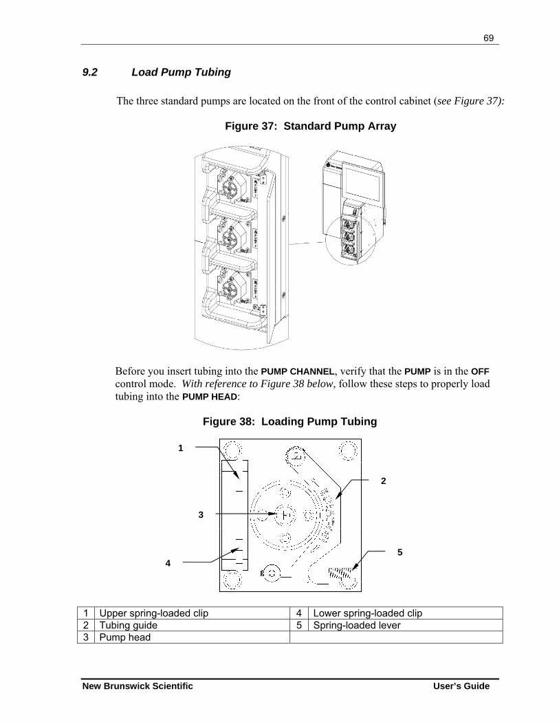
69
New Brunswick Scientific User’s Guide
9.2 Load Pump Tubing
The three standard pumps are located on the front of the control cabinet (see Figure 37):
Figure 37: Standard Pump Array
Before you insert tubing into the PUMP CHANNEL, verify that the PUMP is in the OFF control mode. With reference to Figure 38 below, follow these steps to properly load tubing into the PUMP HEAD:
Figure 38: Loading Pump Tubing
1 Upper spring-loaded clip 4 Lower spring-loaded clip 2 Tubing guide 5 Spring-loaded lever 3 Pump head
5
2
3
1
4
70
BioFlo 310 M1287-0054 User’s Guide
1. Open the PUMP cover to gain access to the interior of the pump. 2. Select the desired tubing size (see Table 6 in Section 13.3 for reference) and cut a
length sufficient to reach from the inlet source, through the pump, and to the outlet recipient, allowing a few extra inches.
3. Form a loop large enough to go around the pump head. 4. Pull the right side of the spring-loaded lever down to release the tubing guide. 5. Hold the upper spring-loaded clip open and load the upper clip channel; allow the
upper clip to close over the tubing. 6. Lift the tubing guide up to the right, and thread the tubing around the pump head,
anchoring the tubing with one finger. 7. Pulling the loop taut, open the lower spring-loaded clip, load the lower clip
channel.
WARNING! Be careful not to pinch your fingers in the pump head levers.
8. Let the tubing guide drop down to hold the tubing in place, and close the spring-loaded lever. Make sure it snaps shut.
9. Press and hold the pump mode Prime button or change the pump mode to ON at 100% setpoint and ensure that the pump operates smoothly.
See Section 10.5 for details on pump assignment and Section 13 for details on pump set-up and operation.
9.3 Confirm pH Calibration
Autoclaving can alter the zero characteristics of pH probes, typically by 0.1-0.3 pH. To check, and to compensate for any discrepancy, you will need an accurate external pH meter. 1. Following sterilization, with the media at room temperature, note the pH value on
the BioFlo 310 SUMMARY screen. 2. Take a sample of media and measure the pH using the external meter. 3. If the two values disagree, return to the pH calibration screen (see Section 7.2) and
Set Zero to the value reported by the external meter. Do not change the Span or you will invalidate the entire calibration.
The pH value will now agree with the external meter’s reading.
71
New Brunswick Scientific User’s Guide
9.4 Install Liquid Addition Systems
Figure 39 is a simple depiction of a typical addition system. Depending on the liquids (base, acid, nutrients, media) to be added, your system may be slightly different.
1. Aseptically install (if applicable) a sterile (0.2µm) filter in one of the two
penetrations on the addition bottle cap. 2. Aseptically connect the tubing, securing it with a plastic tie, to the harvest tube in
the addition bottle. Clamp it off at the top. 3. If you have not already done so, thread the tubing through the selected feed pump. 4. Connect the tubing, securing it with a plastic tie, to the appropriate addition port on
the headplate. 5. Remove the clamp.
CAUTION! Proper pH control is critically dependent on tubing size, which should be as small as possible. Consult Table 6, the flow rate/tubing size chart, for guidance.
9.4.1 Addition Tubing Size
pH can be controlled by automatic additions of liquid acid and base. Additions are triggered by the BioFlo 310 controller, which is constantly comparing current pH value with the pH setpoint and making adjustments as necessary. The concentrations of acid and base, and the inner diameter of the acid and base addition tubing (where they pass through the peristaltic pumps), are critical parameters in the proper operation of a P&I pH control system. If the tubing is too large, excessive doses will be added. The result is that the system will “overcontrol,” alternating in close succession between adding one liquid, then the other, providing little or no change in pH reading. A user-selected deadband value is an aid to control pH within the user-assigned range: no acid or base will be added when the pH value falls within the deadband tolerance above or below the setpoint.
5-normal solutions make a good trade-off between moderate addition volume and good control characteristics. The correct tubing diameter varies a little with process, but inside diameters as small as 0.2 mm sometimes eliminate over- control while supplying sufficient liquid during high-demand culture phases.
NOTE: Whatever the tubing ID, the tubing wall thickness must be 1/16 inch/1.6 mm.
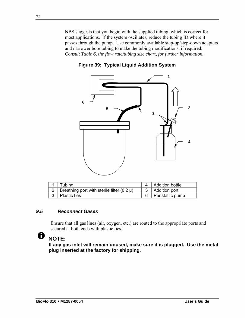
72
BioFlo 310 M1287-0054 User’s Guide
NBS suggests that you begin with the supplied tubing, which is correct for most applications. If the system oscillates, reduce the tubing ID where it passes through the pump. Use commonly available step-up/step-down adapters and narrower bore tubing to make the tubing modifications, if required. Consult Table 6, the flow rate/tubing size chart, for further information.
Figure 39: Typical Liquid Addition System
1 Tubing 4 Addition bottle 2 Breathing port with sterile filter (0.2 µ) 5 Addition port 3 Plastic ties 6 Peristaltic pump
9.5 Reconnect Gases
Ensure that all gas lines (air, oxygen, etc.) are routed to the appropriate ports and secured at both ends with plastic ties.
NOTE: If any gas inlet will remain unused, make sure it is plugged. Use the metal plug inserted at the factory for shipping.
6
4
2 5
1
3
73
New Brunswick Scientific User’s Guide
9.6 Install Temperature (RTD) Probe
CAUTION! Proper installation of the RTD probe is essential to temperature control.
1. Turn the power switch ON. 2. Add 1-2 ml of glycerin to the thermowell and insert the RTD temperature probe. 3. Attach the RTD cable to the RTD connector on the control cabinet. 4. Set agitation (AGIT) to the desired speed and then set its control mode to AUTO. 5. Set TEMP to the desired working temperature, and set its control mode to AUTO.
74
BioFlo 310 M1287-0054 User’s Guide
1100 GGEETTTTIINNGG SSTTAARRTTEEDD
10.1 Control Modes
A control mode is the logic by which a controller generates the desired control signal. The operator has a choice of control modes, the most common of which are ON, OFF, AUTO and MANUAL. In cascaded control, one sensor influences an actuator that is normally associated with a different sensor. The onscreen control mode choice will be the name of the loop chosen to have influence on the actuator.
10.2 Setting P & I Values
P & I values are numbers that determine how the fermentor responds to changing growth conditions and new setpoints. These are listed in each loop’s GAUGE screen. You may need to modify P&I values to suit your particular process. To do so, press inside the Proportional & Integral edit boxes, each time entering the desired value using the popup keypad.
NOTE: If you change P&I values, you can return to the original settings at any time by pressing the Factory Default button (see Figure 19).
10.3 Loop Setpoints
The setpoint is the value you want each loop to attain. When the loop control mode is AUTO, the fermentor will automatically make appropriate adjustments to maintain the value at the setpoint.
10.3.1 Entering Setpoints
To enter a setpoint for any loop, follow these steps: 1. Touch either the LoopName box or the Setpoint box for the desired loop on the
SUMMARY screen. In this example, we have selected AGIT. 2. The loop GAUGE screen opens (see Figure 19, repeated on the following page for
easy reference):
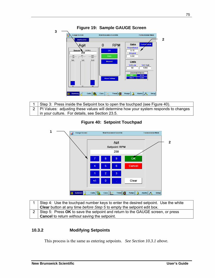
75
New Brunswick Scientific User’s Guide
Figure 19: Sample GAUGE Screen
1 Step 3: Press inside the Setpoint box to open the touchpad (see Figure 40). 2 PI Values: adjusting these values will determine how your system responds to changes
in your culture. For details, see Section 23.5.
Figure 40: Setpoint Touchpad
1 Step 4: Use the touchpad number keys to enter the desired setpoint. Use the white
Clear button at any time before Step 5 to empty the setpoint edit box. 2 Step 5: Press OK to save the setpoint and return to the GAUGE screen, or press
Cancel to return without saving the setpoint.
10.3.2 Modifying Setpoints
This process is the same as entering setpoints. See Section 10.3.1 above.
1
2
3
2
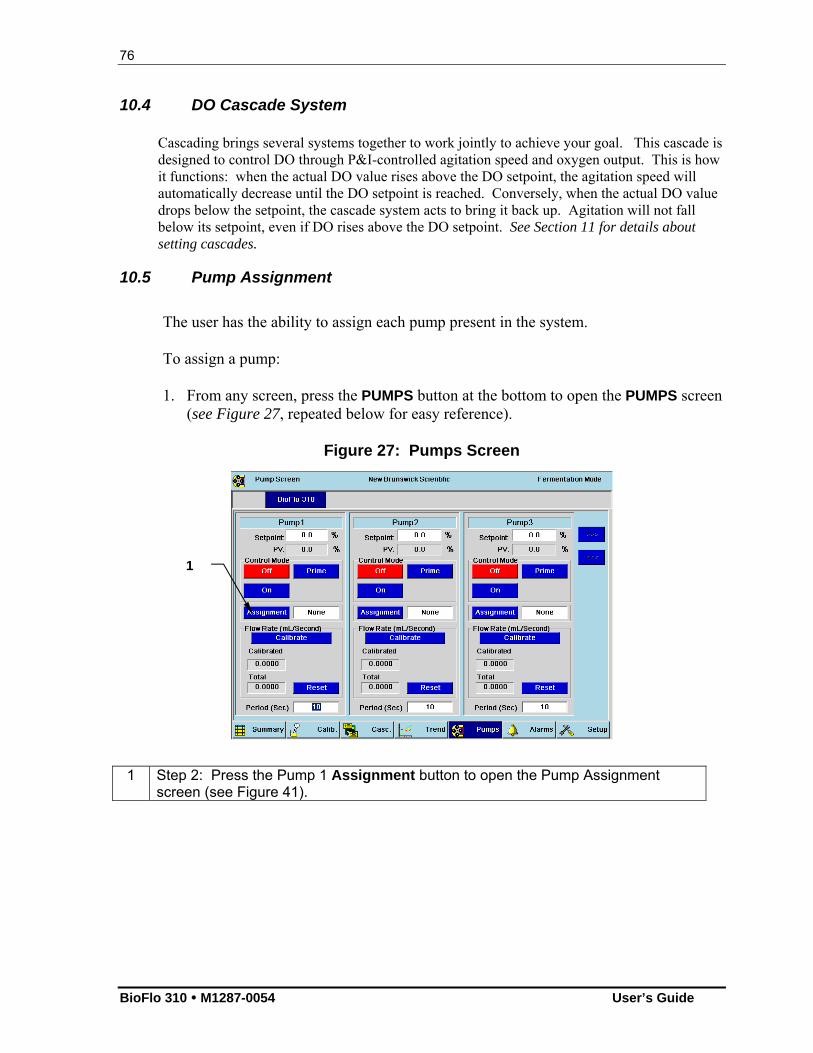
76
BioFlo 310 M1287-0054 User’s Guide
10.4 DO Cascade System
Cascading brings several systems together to work jointly to achieve your goal. This cascade is designed to control DO through P&I-controlled agitation speed and oxygen output. This is how it functions: when the actual DO value rises above the DO setpoint, the agitation speed will automatically decrease until the DO setpoint is reached. Conversely, when the actual DO value drops below the setpoint, the cascade system acts to bring it back up. Agitation will not fall below its setpoint, even if DO rises above the DO setpoint. See Section 11 for details about setting cascades.
10.5 Pump Assignment
The user has the ability to assign each pump present in the system. To assign a pump: 1. From any screen, press the PUMPS button at the bottom to open the PUMPS screen
(see Figure 27, repeated below for easy reference).
Figure 27: Pumps Screen
1 Step 2: Press the Pump 1 Assignment button to open the Pump Assignment screen (see Figure 41).
1
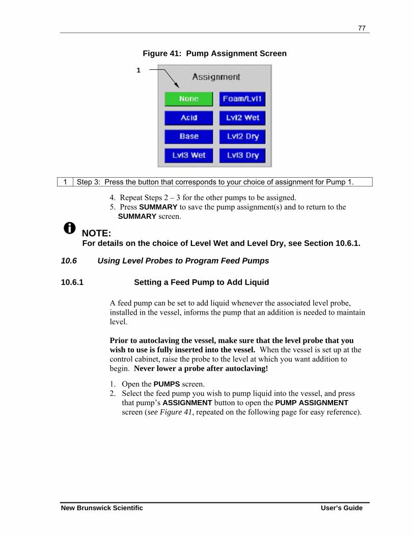
77
New Brunswick Scientific User’s Guide
Figure 41: Pump Assignment Screen
1 Step 3: Press the button that corresponds to your choice of assignment for Pump 1.
4. Repeat Steps 2 – 3 for the other pumps to be assigned. 5. Press SUMMARY to save the pump assignment(s) and to return to the SUMMARY screen.
NOTE: For details on the choice of Level Wet and Level Dry, see Section 10.6.1.
10.6 Using Level Probes to Program Feed Pumps
10.6.1 Setting a Feed Pump to Add Liquid
A feed pump can be set to add liquid whenever the associated level probe, installed in the vessel, informs the pump that an addition is needed to maintain level. Prior to autoclaving the vessel, make sure that the level probe that you wish to use is fully inserted into the vessel. When the vessel is set up at the control cabinet, raise the probe to the level at which you want addition to begin. Never lower a probe after autoclaving!
1. Open the PUMPS screen. 2. Select the feed pump you wish to pump liquid into the vessel, and press
that pump’s ASSIGNMENT button to open the PUMP ASSIGNMENT screen (see Figure 41, repeated on the following page for easy reference).
1
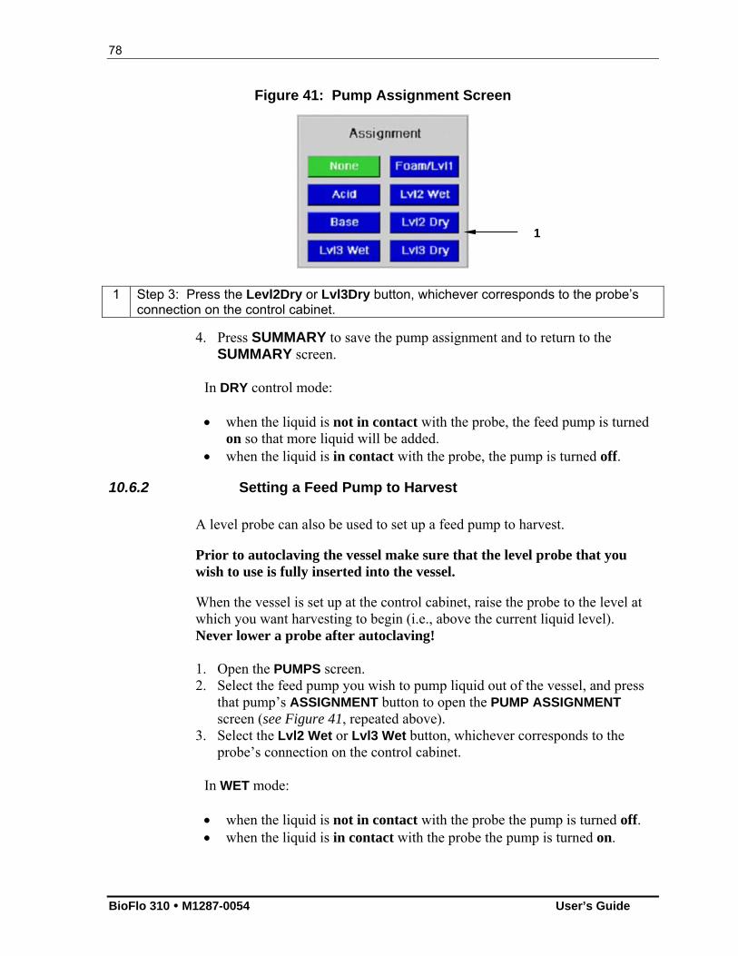
78
BioFlo 310 M1287-0054 User’s Guide
Figure 41: Pump Assignment Screen
1 Step 3: Press the Levl2Dry or Lvl3Dry button, whichever corresponds to the probe’s connection on the control cabinet.
4. Press SUMMARY to save the pump assignment and to return to the SUMMARY screen.
In DRY control mode: when the liquid is not in contact with the probe, the feed pump is turned
on so that more liquid will be added. when the liquid is in contact with the probe, the pump is turned off.
10.6.2 Setting a Feed Pump to Harvest
A level probe can also be used to set up a feed pump to harvest. Prior to autoclaving the vessel make sure that the level probe that you wish to use is fully inserted into the vessel. When the vessel is set up at the control cabinet, raise the probe to the level at which you want harvesting to begin (i.e., above the current liquid level). Never lower a probe after autoclaving! 1. Open the PUMPS screen. 2. Select the feed pump you wish to pump liquid out of the vessel, and press
that pump’s ASSIGNMENT button to open the PUMP ASSIGNMENT screen (see Figure 41, repeated above).
3. Select the Lvl2 Wet or Lvl3 Wet button, whichever corresponds to the probe’s connection on the control cabinet.
In WET mode: when the liquid is not in contact with the probe the pump is turned off. when the liquid is in contact with the probe the pump is turned on.
1
79
New Brunswick Scientific User’s Guide
10.6.3 Level Control Off
When OFF is selected from any level (Foam, HiFoam, Lvl2 Wet, Lvl3 Wet, Lvl 2 Dry, Lvl3 Dry, Acid or Base) control mode menu, the pump is off.
10.6.4 Pump Calibration
Pump flow rates are provided in Table 6 (Section 13.3). However, more accurate flow rates through the various lines may be established by pre-calibrating the pumps, using the PUMPS screen. This screen controls all pump parameters for the three standard fixed speed pumps supplied with each control cabinet and for any additional pumps added through the available analog input and output connections. Using the PUMPS screen, you can view total pump flow rate in ml/second and set the pump’s cycle time, and assign each pump to one of eight functions (None, Acid, Base, Foam/Lvl1, Lvl2Wet, Lvl2Dry, Lvl3Wet or Lvl3Dry—any “level dry” function turns the pump on when the probe is not in contact with liquid; see Section 10.5 for details).
NOTE: To assure the most accurate flow rate, calibrate the pump (see Section 13.3) each time you change tubing.
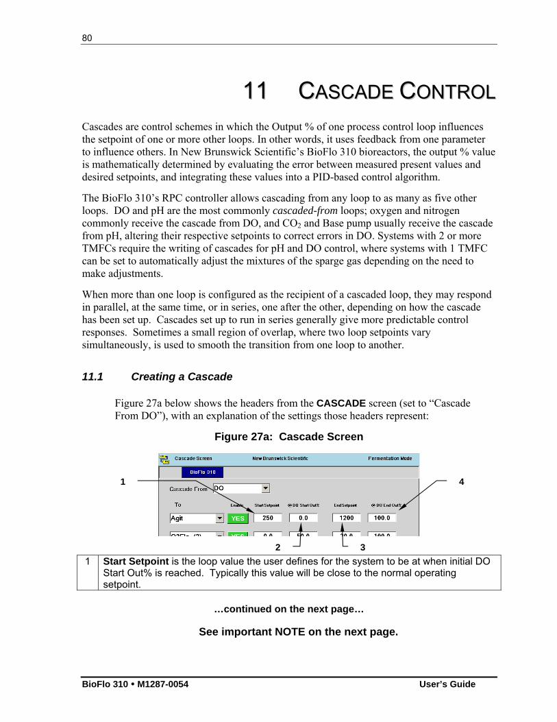
80
BioFlo 310 M1287-0054 User’s Guide
1111 CCAASSCCAADDEE CCOONNTTRROOLL Cascades are control schemes in which the Output % of one process control loop influences the setpoint of one or more other loops. In other words, it uses feedback from one parameter to influence others. In New Brunswick Scientific’s BioFlo 310 bioreactors, the output % value is mathematically determined by evaluating the error between measured present values and desired setpoints, and integrating these values into a PID-based control algorithm.
The BioFlo 310’s RPC controller allows cascading from any loop to as many as five other loops. DO and pH are the most commonly cascaded-from loops; oxygen and nitrogen commonly receive the cascade from DO, and CO2 and Base pump usually receive the cascade from pH, altering their respective setpoints to correct errors in DO. Systems with 2 or more TMFCs require the writing of cascades for pH and DO control, where systems with 1 TMFC can be set to automatically adjust the mixtures of the sparge gas depending on the need to make adjustments.
When more than one loop is configured as the recipient of a cascaded loop, they may respond in parallel, at the same time, or in series, one after the other, depending on how the cascade has been set up. Cascades set up to run in series generally give more predictable control responses. Sometimes a small region of overlap, where two loop setpoints vary simultaneously, is used to smooth the transition from one loop to another.
11.1 Creating a Cascade
Figure 27a below shows the headers from the CASCADE screen (set to “Cascade From DO”), with an explanation of the settings those headers represent:
Figure 27a: Cascade Screen
1 Start Setpoint is the loop value the user defines for the system to be at when initial DO Start Out% is reached. Typically this value will be close to the normal operating setpoint.
…continued on the next page…
See important NOTE on the next page.
1 4
3 2
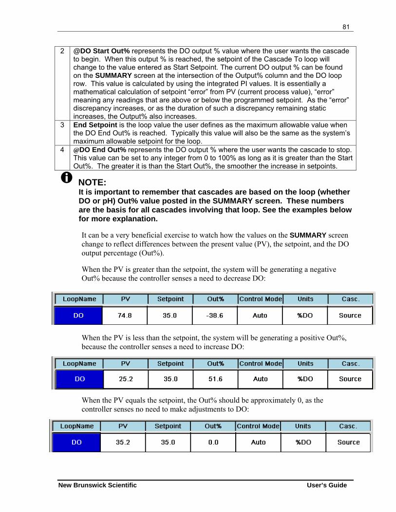
81
New Brunswick Scientific User’s Guide
2 @DO Start Out% represents the DO output % value where the user wants the cascade to begin. When this output % is reached, the setpoint of the Cascade To loop will change to the value entered as Start Setpoint. The current DO output % can be found on the SUMMARY screen at the intersection of the Output% column and the DO loop row. This value is calculated by using the integrated PI values. It is essentially a mathematical calculation of setpoint “error” from PV (current process value), “error” meaning any readings that are above or below the programmed setpoint. As the “error” discrepancy increases, or as the duration of such a discrepancy remaining static increases, the Output% also increases.
3 End Setpoint is the loop value the user defines as the maximum allowable value when the DO End Out% is reached. Typically this value will also be the same as the system’s maximum allowable setpoint for the loop.
4 @DO End Out% represents the DO output % where the user wants the cascade to stop. This value can be set to any integer from 0 to 100% as long as it is greater than the Start Out%. The greater it is than the Start Out%, the smoother the increase in setpoints.
NOTE: It is important to remember that cascades are based on the loop (whether DO or pH) Out% value posted in the SUMMARY screen. These numbers are the basis for all cascades involving that loop. See the examples below for more explanation.
It can be a very beneficial exercise to watch how the values on the SUMMARY screen change to reflect differences between the present value (PV), the setpoint, and the DO output percentage (Out%). When the PV is greater than the setpoint, the system will be generating a negative Out% because the controller senses a need to decrease DO:
When the PV is less than the setpoint, the system will be generating a positive Out%, because the controller senses a need to increase DO:
When the PV equals the setpoint, the Out% should be approximately 0, as the controller senses no need to make adjustments to DO:
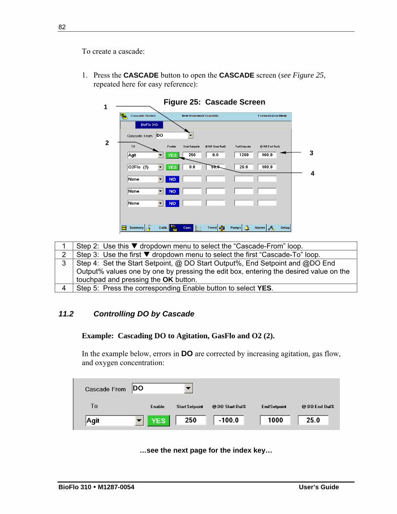
82
BioFlo 310 M1287-0054 User’s Guide
To create a cascade:
1. Press the CASCADE button to open the CASCADE screen (see Figure 25,
repeated here for easy reference):
Figure 25: Cascade Screen
1 Step 2: Use this dropdown menu to select the “Cascade-From” loop. 2 Step 3: Use the first dropdown menu to select the first “Cascade-To” loop. 3 Step 4: Set the Start Setpoint, @ DO Start Output%, End Setpoint and @DO End
Output% values one by one by pressing the edit box, entering the desired value on the touchpad and pressing the OK button.
4 Step 5: Press the corresponding Enable button to select YES.
11.2 Controlling DO by Cascade
Example: Cascading DO to Agitation, GasFlo and O2 (2). In the example below, errors in DO are corrected by increasing agitation, gas flow, and oxygen concentration:
…see the next page for the index key…
(1)
1
2
3
4
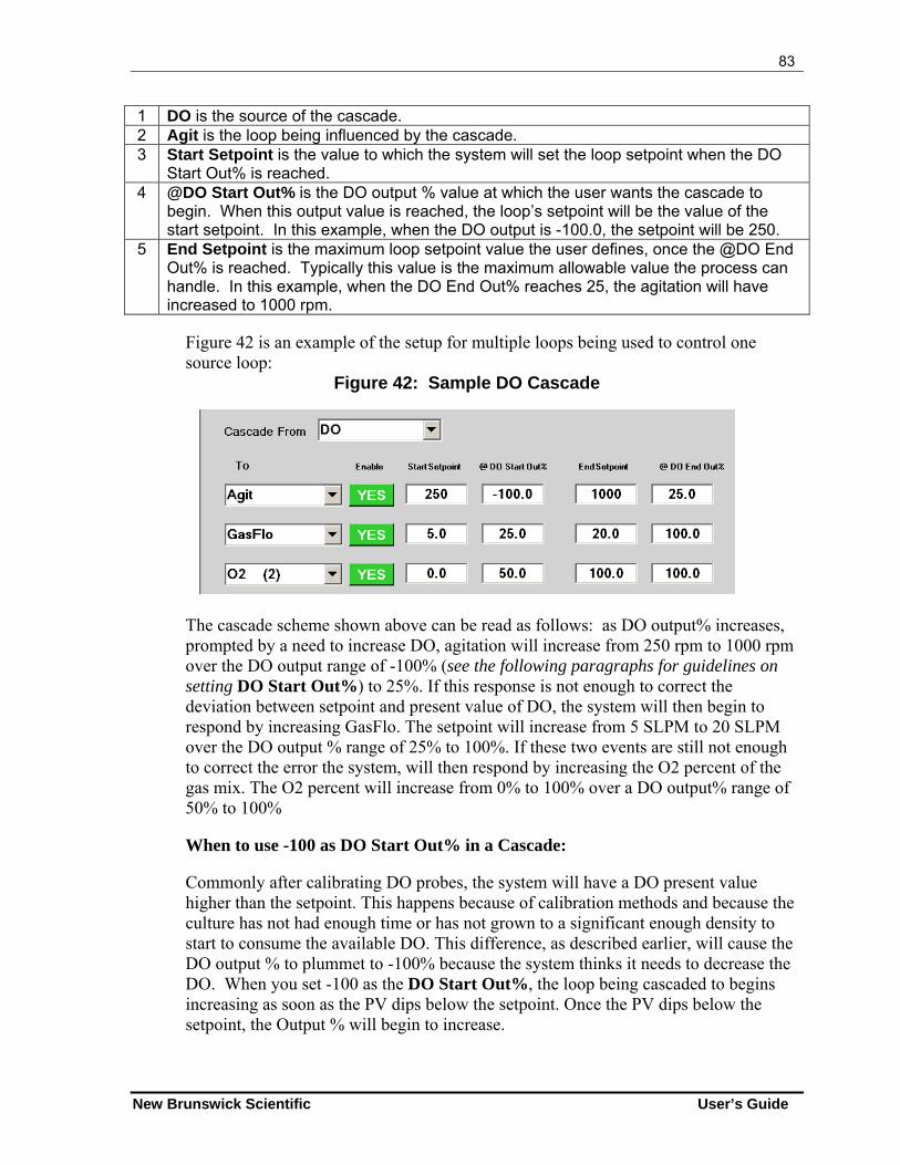
83
New Brunswick Scientific User’s Guide
1 DO is the source of the cascade. 2 Agit is the loop being influenced by the cascade. 3 Start Setpoint is the value to which the system will set the loop setpoint when the DO
Start Out% is reached. 4 @DO Start Out% is the DO output % value at which the user wants the cascade to
begin. When this output value is reached, the loop’s setpoint will be the value of the start setpoint. In this example, when the DO output is -100.0, the setpoint will be 250.
5 End Setpoint is the maximum loop setpoint value the user defines, once the @DO End Out% is reached. Typically this value is the maximum allowable value the process can handle. In this example, when the DO End Out% reaches 25, the agitation will have increased to 1000 rpm.
Figure 42 is an example of the setup for multiple loops being used to control one source loop:
Figure 42: Sample DO Cascade
The cascade scheme shown above can be read as follows: as DO output% increases, prompted by a need to increase DO, agitation will increase from 250 rpm to 1000 rpm over the DO output range of -100% (see the following paragraphs for guidelines on setting DO Start Out%) to 25%. If this response is not enough to correct the deviation between setpoint and present value of DO, the system will then begin to respond by increasing GasFlo. The setpoint will increase from 5 SLPM to 20 SLPM over the DO output % range of 25% to 100%. If these two events are still not enough to correct the error the system, will then respond by increasing the O2 percent of the gas mix. The O2 percent will increase from 0% to 100% over a DO output% range of 50% to 100%
When to use -100 as DO Start Out% in a Cascade: Commonly after calibrating DO probes, the system will have a DO present value higher than the setpoint. This happens because of calibration methods and because the culture has not had enough time or has not grown to a significant enough density to start to consume the available DO. This difference, as described earlier, will cause the DO output % to plummet to -100% because the system thinks it needs to decrease the DO. When you set -100 as the DO Start Out%, the loop being cascaded to begins increasing as soon as the PV dips below the setpoint. Once the PV dips below the setpoint, the Output % will begin to increase.
84
BioFlo 310 M1287-0054 User’s Guide
When to use 0 as DO Start Out% in a Cascade: Zero should be used as the DO Start Out% if the media is equilibrated to the desired setpoints before inoculation or before the cascade is enabled. In other words, if the DO setpoint and DO PV are close to equal at the start of a run, it will work best if the cascade DO Start Out% is 0. When configured this way, any drop in DO below the setpoint will be compensated by the cascade loop.
NOTE: Regardless of DO (cascaded-from) output, the setpoint of any cascade-
to loop will not go below its own Minimum Setpoint value. Minimum Output% corresponds to the minimum value that will produce
the minimum setpoint; lower outputs will not affect setpoint. Regardless of DO output, the setpoint of any cascade-to loop will not
rise above its own maximum setpoint.
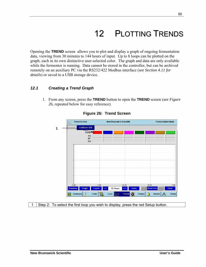
85
New Brunswick Scientific User’s Guide
1122 PPLLOOTTTTIINNGG TTRREENNDDSS Opening the TREND screen allows you to plot and display a graph of ongoing fermentation data, viewing from 30 minutes to 144 hours of input. Up to 8 loops can be plotted on the graph, each in its own distinctive user-selected color. The graph and data are only available while the fermentor is running. Data cannot be stored in the controller, but can be archived remotely on an auxiliary PC via the RS232/422 Modbus interface (see Section 4.11 for details) or saved to a USB storage device.
12.1 Creating a Trend Graph
1. From any screen, press the TREND button to open the TREND screen (see Figure
26, repeated below for easy reference).
Figure 26: Trend Screen
1 Step 2: To select the first loop you wish to display, press the red Setup button.
1
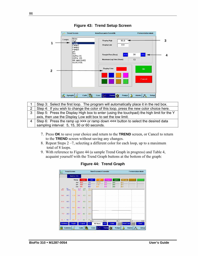
86
BioFlo 310 M1287-0054 User’s Guide
Figure 43: Trend Setup Screen
1 Step 3: Select the first loop. The program will automatically place it in the red box. 2 Step 4: If you wish to change the color of this loop, press the new color choice here. 3 Step 5: Press the Display High box to enter (using the touchpad) the high limit for the Y
axis, then use the Display Low edit box to set the low limit. 4 Step 6: Press the ramp up >>> or ramp down <<< button to select the desired data
sampling interval: 5, 15, 30 or 60 seconds.
7. Press OK to save your choice and return to the TREND screen, or Cancel to return to the TREND screen without saving any changes. 8. Repeat Steps 2 –7, selecting a different color for each loop, up to a maximum total of 8 loops. 9. With reference to Figure 44 (a sample Trend Graph in progress) and Table 4, acquaint yourself with the Trend Graph buttons at the bottom of the graph:
Figure 44: Trend Graph
1
2
3
4
87
New Brunswick Scientific User’s Guide
Table 4: Trend Graph Buttons
Button/Feature Description Summary Press this button to cycle through three summary display
modes: all eight loops at once, loops 1-4 (red-fuschia), and loops 5-8 (dark green-light green).
Single Press this button to display the graph for one loop at a time, in the order (left to right) they are displayed in the colored buttons at the top of the screen.
Export Press this button to export a text file containing all of the Trend data. See Section 12.1.1 for detailed instructions.
<<< Ramp Down Press this button to select a lower Timespan or to move the Read Line toward the left of the screen.
[Timespan Indicator] Using the Ramp Down or Ramp up button on either side of this edit box, select the timespan to display onscreen. Preset increments range from 30 Minutes to 144 Hours.
>>> Ramp Up Press this button to select a higher Timespan or to move the Read Line toward the right of the screen.
Zoom Press this button to open an interactive mode where you can zoom in on a section of interest on one plot. The button turns red when you touch it, indicating you are in Zoom mode. See Section 12.1.2 below for detailed instructions.
Read Line Press this button to open an interactive mode where you can move a vertical (cross-sectional) line across the graph to aid in determining a particular reading. See Section 12.1.3 below for detailed instructions.
12.1.1 Using the Export Button
To export Trend data as a text file to a USB external memory device for use with a PC program (e.g., Microsoft Excel®): 1. Install the USB external memory device into one of the USB connections
on the back of the Control Cabinet. 2. Open the TREND screen and push the Export button. 3. In the screen that opens, select the USB external memory device from the
list of available drives. 4. Touch the empty FileName box. Using the touchpad that appears, enter
the desired file name, then press the OK button. 5. Press the Save button to save the file to the USB external memory device. 6. Remove the USB external memory device and use it to download the data
to your PC.
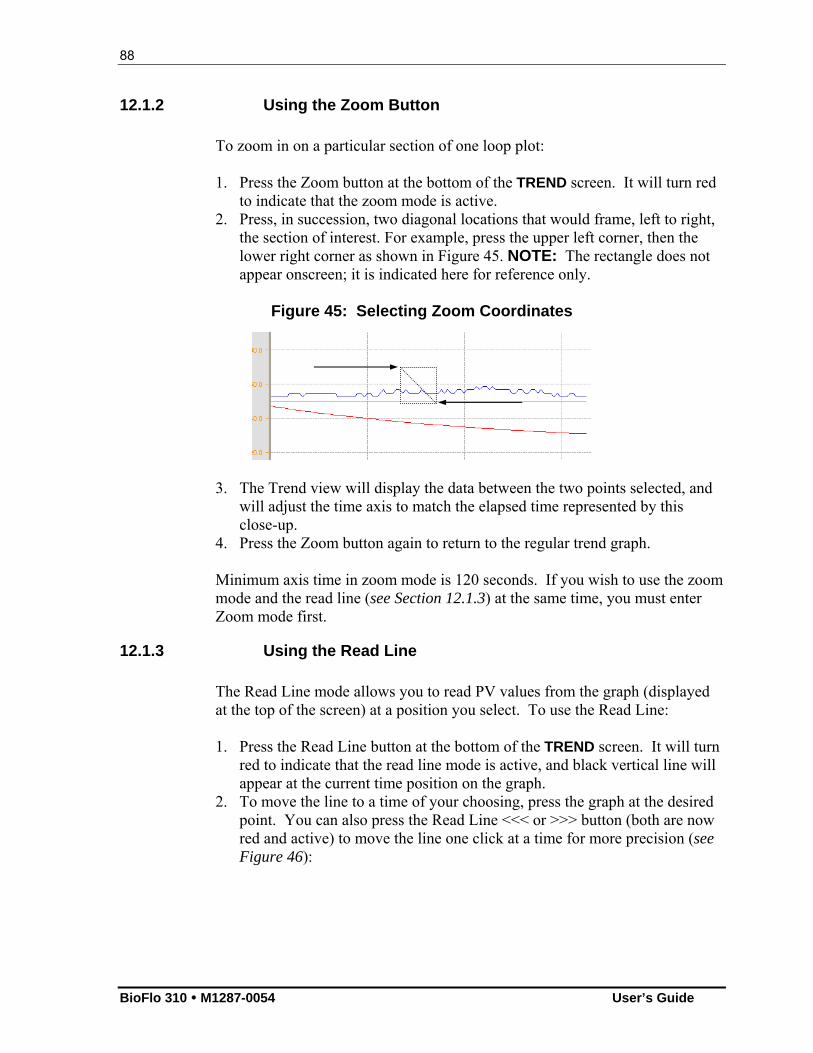
88
BioFlo 310 M1287-0054 User’s Guide
12.1.2 Using the Zoom Button
To zoom in on a particular section of one loop plot: 1. Press the Zoom button at the bottom of the TREND screen. It will turn red
to indicate that the zoom mode is active. 2. Press, in succession, two diagonal locations that would frame, left to right,
the section of interest. For example, press the upper left corner, then the lower right corner as shown in Figure 45. NOTE: The rectangle does not appear onscreen; it is indicated here for reference only.
Figure 45: Selecting Zoom Coordinates
3. The Trend view will display the data between the two points selected, and will adjust the time axis to match the elapsed time represented by this close-up.
4. Press the Zoom button again to return to the regular trend graph.
Minimum axis time in zoom mode is 120 seconds. If you wish to use the zoom mode and the read line (see Section 12.1.3) at the same time, you must enter Zoom mode first.
12.1.3 Using the Read Line
The Read Line mode allows you to read PV values from the graph (displayed at the top of the screen) at a position you select. To use the Read Line: 1. Press the Read Line button at the bottom of the TREND screen. It will turn
red to indicate that the read line mode is active, and black vertical line will appear at the current time position on the graph.
2. To move the line to a time of your choosing, press the graph at the desired point. You can also press the Read Line <<< or >>> button (both are now red and active) to move the line one click at a time for more precision (see Figure 46):
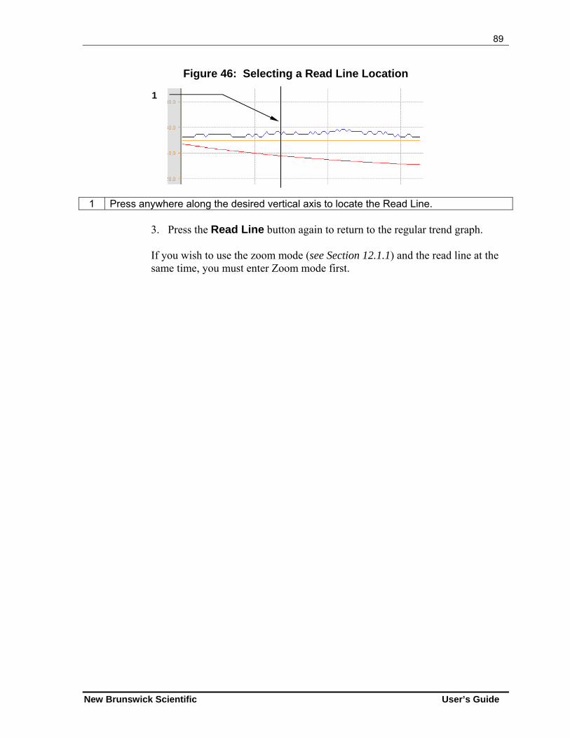
89
New Brunswick Scientific User’s Guide
Figure 46: Selecting a Read Line Location
1 Press anywhere along the desired vertical axis to locate the Read Line.
3. Press the Read Line button again to return to the regular trend graph.
If you wish to use the zoom mode (see Section 12.1.1) and the read line at the same time, you must enter Zoom mode first.
1
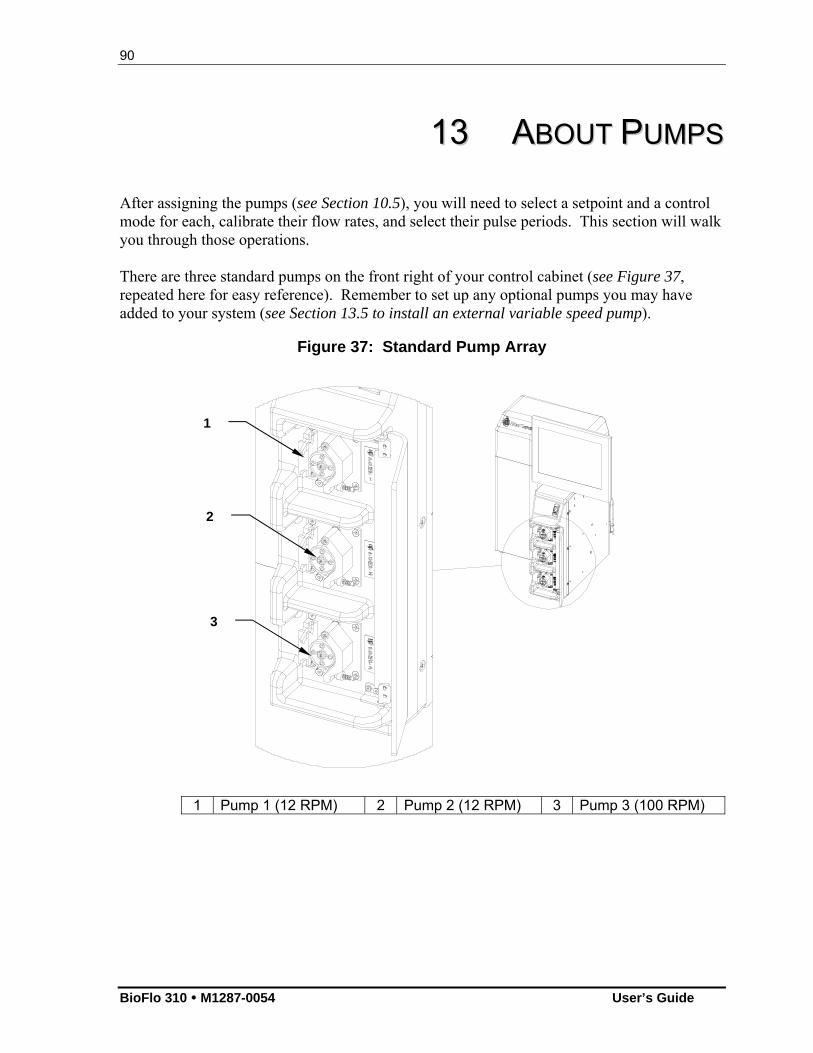
90
BioFlo 310 M1287-0054 User’s Guide
1133 AABBOOUUTT PPUUMMPPSS After assigning the pumps (see Section 10.5), you will need to select a setpoint and a control mode for each, calibrate their flow rates, and select their pulse periods. This section will walk you through those operations. There are three standard pumps on the front right of your control cabinet (see Figure 37, repeated here for easy reference). Remember to set up any optional pumps you may have added to your system (see Section 13.5 to install an external variable speed pump).
Figure 37: Standard Pump Array
1 Pump 1 (12 RPM) 2 Pump 2 (12 RPM) 3 Pump 3 (100 RPM)
1
2
3
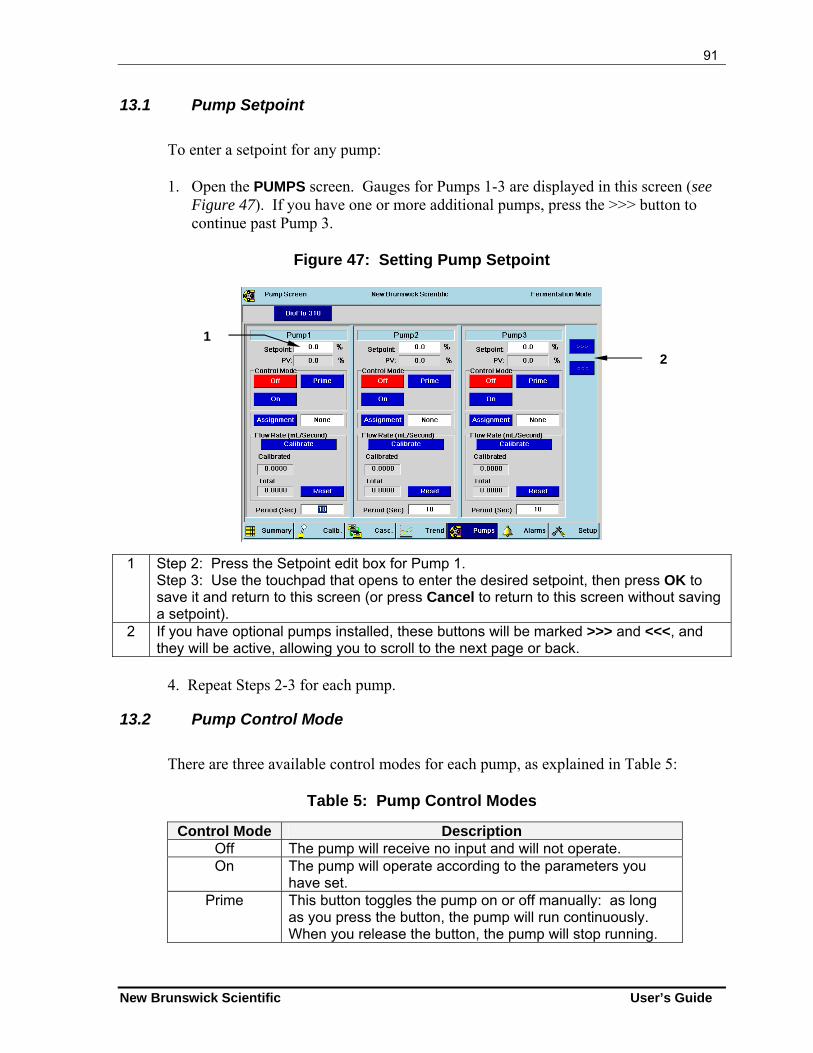
91
New Brunswick Scientific User’s Guide
13.1 Pump Setpoint
To enter a setpoint for any pump: 1. Open the PUMPS screen. Gauges for Pumps 1-3 are displayed in this screen (see
Figure 47). If you have one or more additional pumps, press the >>> button to continue past Pump 3.
Figure 47: Setting Pump Setpoint
1 Step 2: Press the Setpoint edit box for Pump 1. Step 3: Use the touchpad that opens to enter the desired setpoint, then press OK to save it and return to this screen (or press Cancel to return to this screen without saving a setpoint).
2 If you have optional pumps installed, these buttons will be marked >>> and <<<, and they will be active, allowing you to scroll to the next page or back.
4. Repeat Steps 2-3 for each pump.
13.2 Pump Control Mode
There are three available control modes for each pump, as explained in Table 5:
Table 5: Pump Control Modes
Control Mode Description Off The pump will receive no input and will not operate. On The pump will operate according to the parameters you
have set. Prime This button toggles the pump on or off manually: as long
as you press the button, the pump will run continuously. When you release the button, the pump will stop running.
1
2
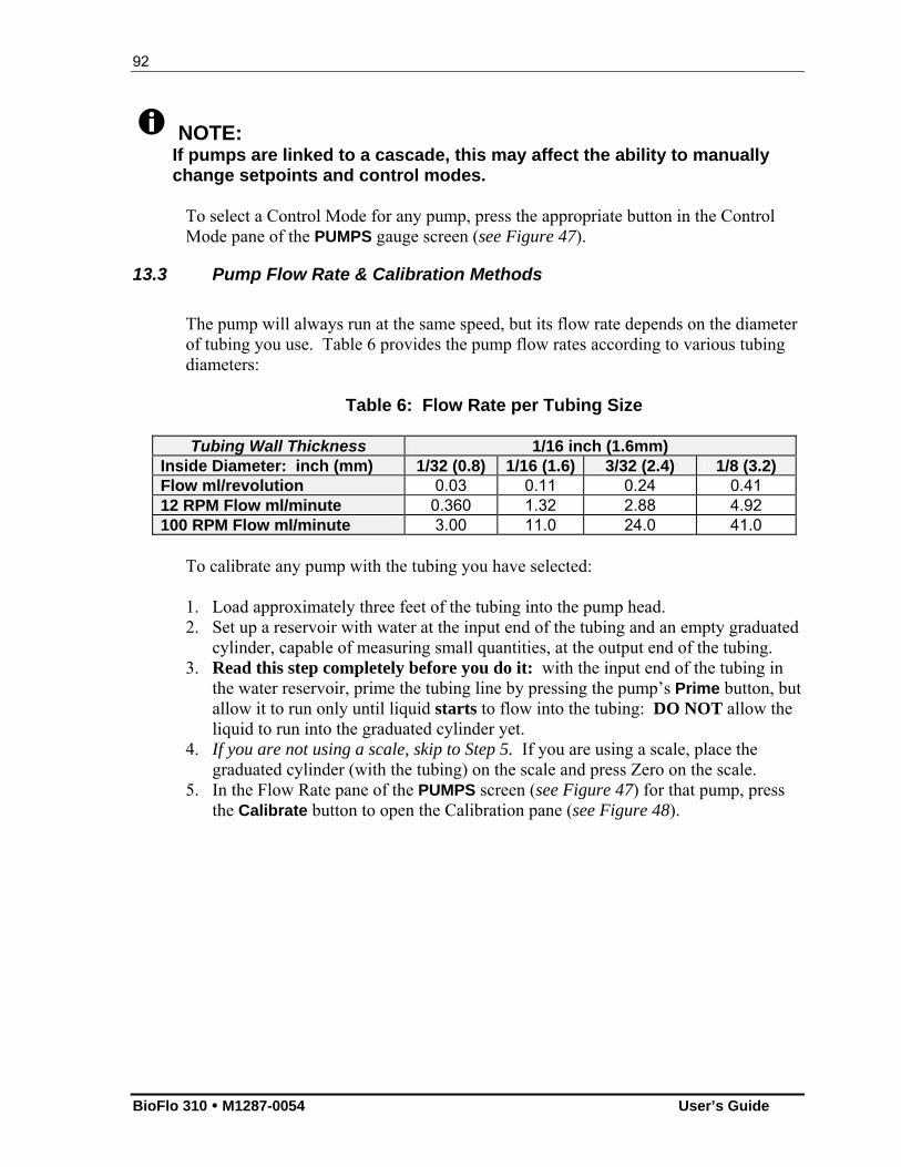
92
BioFlo 310 M1287-0054 User’s Guide
NOTE: If pumps are linked to a cascade, this may affect the ability to manually change setpoints and control modes.
To select a Control Mode for any pump, press the appropriate button in the Control Mode pane of the PUMPS gauge screen (see Figure 47).
13.3 Pump Flow Rate & Calibration Methods
The pump will always run at the same speed, but its flow rate depends on the diameter of tubing you use. Table 6 provides the pump flow rates according to various tubing diameters:
Table 6: Flow Rate per Tubing Size
Tubing Wall Thickness 1/16 inch (1.6mm) Inside Diameter: inch (mm) 1/32 (0.8) 1/16 (1.6) 3/32 (2.4) 1/8 (3.2) Flow ml/revolution 0.03 0.11 0.24 0.41 12 RPM Flow ml/minute 0.360 1.32 2.88 4.92 100 RPM Flow ml/minute 3.00 11.0 24.0 41.0
To calibrate any pump with the tubing you have selected: 1. Load approximately three feet of the tubing into the pump head. 2. Set up a reservoir with water at the input end of the tubing and an empty graduated
cylinder, capable of measuring small quantities, at the output end of the tubing. 3. Read this step completely before you do it: with the input end of the tubing in
the water reservoir, prime the tubing line by pressing the pump’s Prime button, but allow it to run only until liquid starts to flow into the tubing: DO NOT allow the liquid to run into the graduated cylinder yet.
4. If you are not using a scale, skip to Step 5. If you are using a scale, place the graduated cylinder (with the tubing) on the scale and press Zero on the scale.
5. In the Flow Rate pane of the PUMPS screen (see Figure 47) for that pump, press the Calibrate button to open the Calibration pane (see Figure 48).
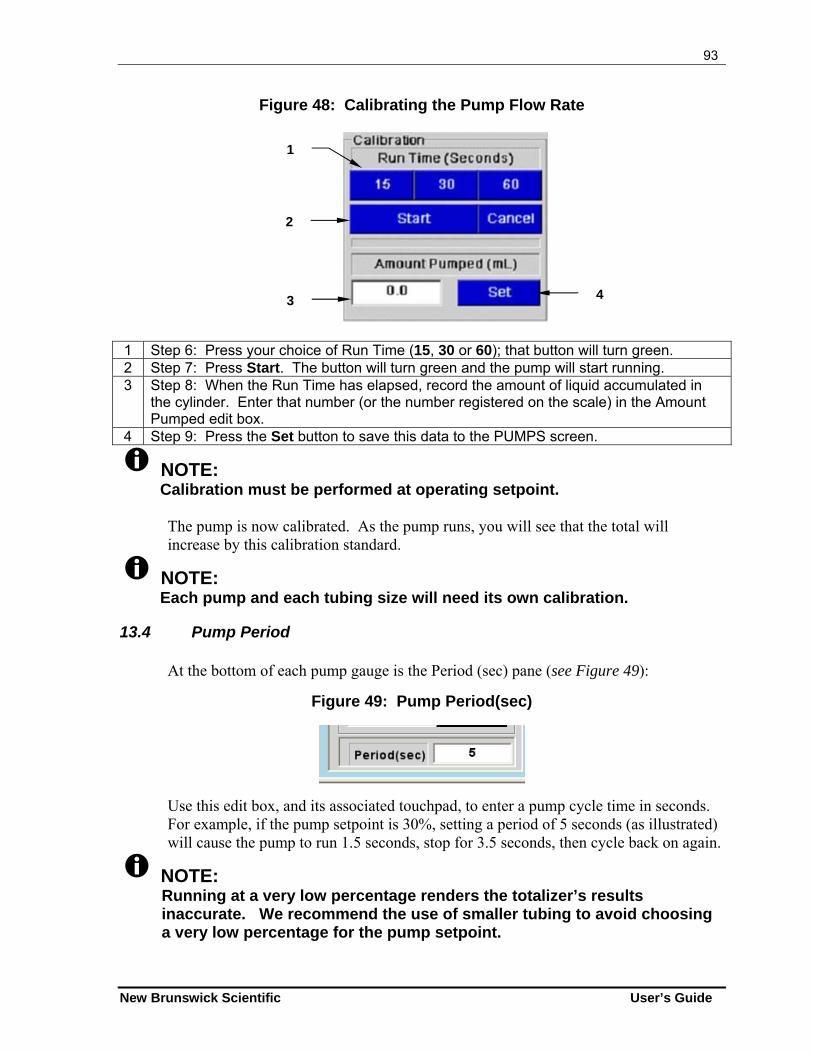
93
New Brunswick Scientific User’s Guide
Figure 48: Calibrating the Pump Flow Rate
1 Step 6: Press your choice of Run Time (15, 30 or 60); that button will turn green. 2 Step 7: Press Start. The button will turn green and the pump will start running. 3 Step 8: When the Run Time has elapsed, record the amount of liquid accumulated in
the cylinder. Enter that number (or the number registered on the scale) in the Amount Pumped edit box.
4 Step 9: Press the Set button to save this data to the PUMPS screen.
NOTE: Calibration must be performed at operating setpoint.
The pump is now calibrated. As the pump runs, you will see that the total will increase by this calibration standard.
NOTE: Each pump and each tubing size will need its own calibration.
13.4 Pump Period
At the bottom of each pump gauge is the Period (sec) pane (see Figure 49):
Figure 49: Pump Period(sec)
Use this edit box, and its associated touchpad, to enter a pump cycle time in seconds. For example, if the pump setpoint is 30%, setting a period of 5 seconds (as illustrated) will cause the pump to run 1.5 seconds, stop for 3.5 seconds, then cycle back on again.
NOTE: Running at a very low percentage renders the totalizer’s results inaccurate. We recommend the use of smaller tubing to avoid choosing a very low percentage for the pump setpoint.
1
2
3 4
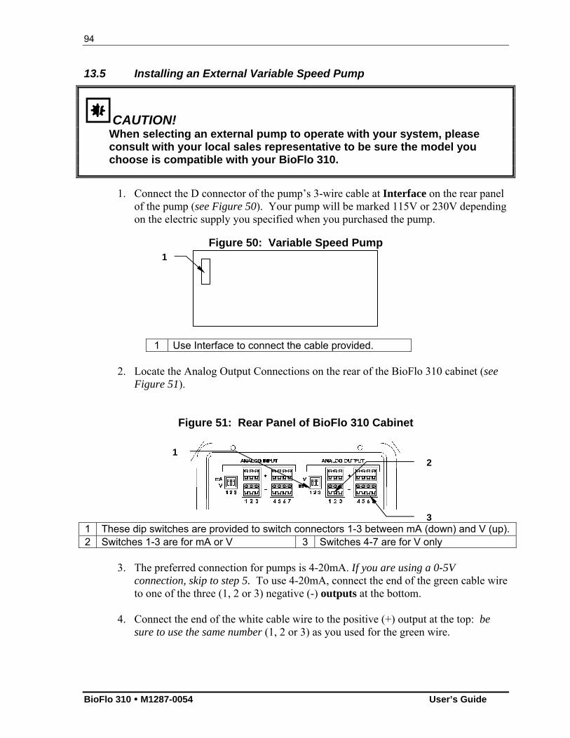
94
BioFlo 310 M1287-0054 User’s Guide
13.5 Installing an External Variable Speed Pump
CAUTION! When selecting an external pump to operate with your system, please consult with your local sales representative to be sure the model you choose is compatible with your BioFlo 310.
1. Connect the D connector of the pump’s 3-wire cable at Interface on the rear panel of the pump (see Figure 50). Your pump will be marked 115V or 230V depending on the electric supply you specified when you purchased the pump.
Figure 50: Variable Speed Pump
1 Use Interface to connect the cable provided.
2. Locate the Analog Output Connections on the rear of the BioFlo 310 cabinet (see Figure 51).
Figure 51: Rear Panel of BioFlo 310 Cabinet
1 These dip switches are provided to switch connectors 1-3 between mA (down) and V (up). 2 Switches 1-3 are for mA or V 3 Switches 4-7 are for V only
3. The preferred connection for pumps is 4-20mA. If you are using a 0-5V connection, skip to step 5. To use 4-20mA, connect the end of the green cable wire to one of the three (1, 2 or 3) negative (-) outputs at the bottom.
4. Connect the end of the white cable wire to the positive (+) output at the top: be
sure to use the same number (1, 2 or 3) as you used for the green wire.
1
1 2
3
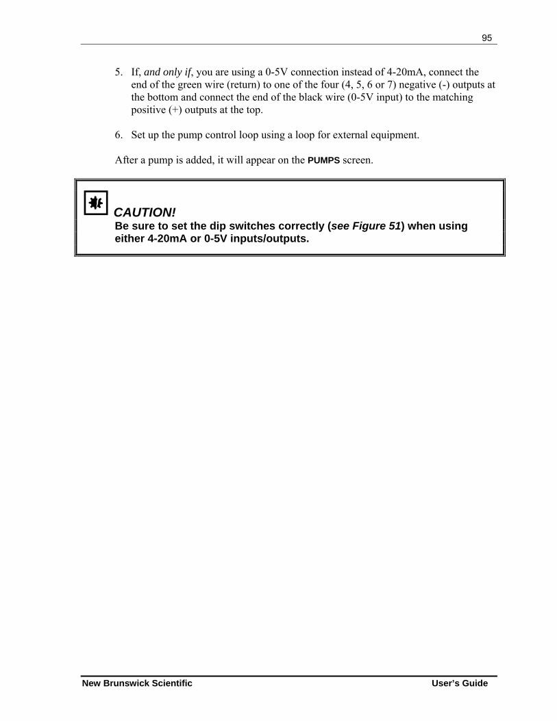
95
New Brunswick Scientific User’s Guide
5. If, and only if, you are using a 0-5V connection instead of 4-20mA, connect the end of the green wire (return) to one of the four (4, 5, 6 or 7) negative (-) outputs at the bottom and connect the end of the black wire (0-5V input) to the matching positive (+) outputs at the top.
6. Set up the pump control loop using a loop for external equipment.
After a pump is added, it will appear on the PUMPS screen.
CAUTION! Be sure to set the dip switches correctly (see Figure 51) when using either 4-20mA or 0-5V inputs/outputs.
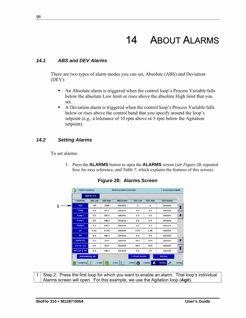
96
BioFlo 310 M1287-0054 User’s Guide
1144 AABBOOUUTT AALLAARRMMSS
14.1 ABS and DEV Alarms
There are two types of alarm modes you can set, Absolute (ABS) and Deviation (DEV): An Absolute alarm is triggered when the control loop’s Process Variable falls
below the absolute Low limit or rises above the absolute High limit that you set.
A Deviation alarm is triggered when the control loop’s Process Variable falls below or rises above the control band that you specify around the loop’s setpoint (e.g., a tolerance of 10 rpm above or 5 rpm below the Agitation setpoint).
14.2 Setting Alarms
To set alarms:
1. Press the ALARMS button to open the ALARMS screen (see Figure 28, repeated here for easy reference, and Table 7, which explains the features of this screen).
Figure 28: Alarms Screen
1 Step 2: Press the first loop for which you want to enable an alarm. That loop’s individual
Alarms screen will open. For this example, we use the Agitation loop (Agit).
1
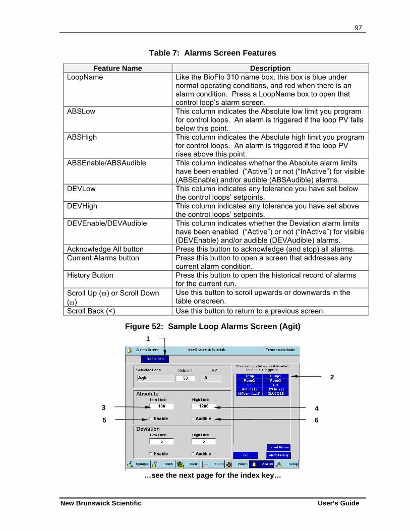
97
New Brunswick Scientific User’s Guide
Table 7: Alarms Screen Features
Feature Name Description LoopName Like the BioFlo 310 name box, this box is blue under
normal operating conditions, and red when there is an alarm condition. Press a LoopName box to open that control loop’s alarm screen.
ABSLow This column indicates the Absolute low limit you program for control loops. An alarm is triggered if the loop PV falls below this point.
ABSHigh This column indicates the Absolute high limit you program for control loops. An alarm is triggered if the loop PV rises above this point.
ABSEnable/ABSAudible This column indicates whether the Absolute alarm limits have been enabled (“Active”) or not (“InActive”) for visible (ABSEnable) and/or audible (ABSAudible) alarms.
DEVLow This column indicates any tolerance you have set below the control loops’ setpoints.
DEVHigh This column indicates any tolerance you have set above the control loops’ setpoints.
DEVEnable/DEVAudible This column indicates whether the Deviation alarm limits have been enabled (“Active”) or not (“InActive”) for visible (DEVEnable) and/or audible (DEVAudible) alarms.
Acknowledge All button Press this button to acknowledge (and stop) all alarms. Current Alarms button Press this button to open a screen that addresses any
current alarm condition. History Button Press this button to open the historical record of alarms
for the current run. Scroll Up () or Scroll Down ()
Use this button to scroll upwards or downwards in the table onscreen.
Scroll Back (<) Use this button to return to a previous screen.
Figure 52: Sample Loop Alarms Screen (Agit)
…see the next page for the index key…
3 4
5 6
1
2
98
BioFlo 310 M1287-0054 User’s Guide
1 In an alarm condition, this name box turns red, 2 Pressing any of these loop buttons will cause the selected loop(s) to shut down when an
alarm is triggered for (in this sample) the Agit loop. 3 Step 3: If you wish to set an Absolute alarm, enter an Absolute Low limit here… 4 …and enter an Absolute High Limit here. 5 Step 4: Press here to enable the Visual Absolute alarm. 6 Step 5: Press here to enable the Audible Absolute alarm.
6. If you wish to set a Deviation alarm, use the Deviation pane and follow
the same procedure as outlined in Steps 3-5 above. 7. Use the Scroll Back button (<<<) to return to the main Alarms screen and
follow these steps for any other alarms you wish to set, or press the SUMMARY button to return to the SUMMARY screen.
14.3 Acknowledging an Alarm
When an alarm condition develops, the LoopName box on the SUMMARY screen for the control loop involved will turn from blue to red, as will the BioFlo 310 name box. This is the Visual alarm. A footnote, written in red, will also appear in order to identify the nature of the alarm (e.g., Unit 1—Deviation Low Error). The Visible alarm will remain onscreen until the alarm condition is rectified. If the Audible alarm is also enabled, beeping will occur until the alarm is acknowledged. There are three ways to acknowledge alarms: (1) one alarm at a time, (2) all alarms for one control loop at a time, and (3) all alarms for all control loops at a time, for the rare occasion such a condition should arise. To acknowledge one alarm at a time: 1. Press the ALARMS screen button to open the ALARMS screen. 2. Press the red LoopName box to open that control loop’s ALARMS screen. 3. Press the Current Alarms button to open the Current Alarms Summary screen. 4. Press the Index box for the alarm you wish to acknowledge. It will turn green. 5. Press the Acknowledge button. The alarm will be deleted from the screen. 6. Repeat Steps 4 & 5 for any other alarms recorded for this loop. 7. Press the Scroll Back (<<<) button to return to the ALARMS screen. 8. Repeat Steps 2-7 for any other control loop alarms.
To acknowledge all alarms simultaneously for one control loop: 1. Press the ALARMS screen button to open the ALARMS screen. 2. Press the red LoopName box to open that control loop’s ALARMS screen. 3. Press the Current Alarms button to open the Current Alarms Summary screen. 4. Press the Acknowledge All button. All alarms will be deleted from this screen. 5. Press the Scroll Back (<<<) button to return to the ALARMS screen.
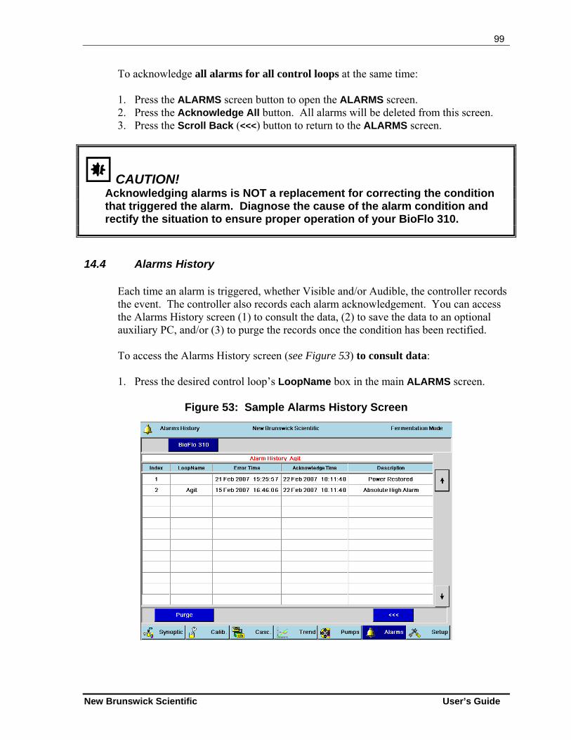
99
New Brunswick Scientific User’s Guide
To acknowledge all alarms for all control loops at the same time: 1. Press the ALARMS screen button to open the ALARMS screen. 2. Press the Acknowledge All button. All alarms will be deleted from this screen. 3. Press the Scroll Back (<<<) button to return to the ALARMS screen.
CAUTION! Acknowledging alarms is NOT a replacement for correcting the condition that triggered the alarm. Diagnose the cause of the alarm condition and rectify the situation to ensure proper operation of your BioFlo 310.
14.4 Alarms History
Each time an alarm is triggered, whether Visible and/or Audible, the controller records the event. The controller also records each alarm acknowledgement. You can access the Alarms History screen (1) to consult the data, (2) to save the data to an optional auxiliary PC, and/or (3) to purge the records once the condition has been rectified. To access the Alarms History screen (see Figure 53) to consult data: 1. Press the desired control loop’s LoopName box in the main ALARMS screen.
Figure 53: Sample Alarms History Screen
100
BioFlo 310 M1287-0054 User’s Guide
2. In the control loop’s Alarms Screen that opens, press the Alarm History button. 3. Press the Scroll Down () or Scroll Up () button to read through the data. 4. Press the Scroll Back (<<<) button to return to the ALARMS screen. To access the Alarms History screen to purge the history: 1. Press the desired control loop’s LoopName box in the main ALARMS screen. 2. In the control loop’s Alarms Screen that opens, press the Alarm History button. 3. Press the Purge button to erase all records.
NOTE: You cannot delete one record at a time; you can only purge all records simultaneously.
4. Press the Scroll Back (<<<) button to return to the ALARMS screen.
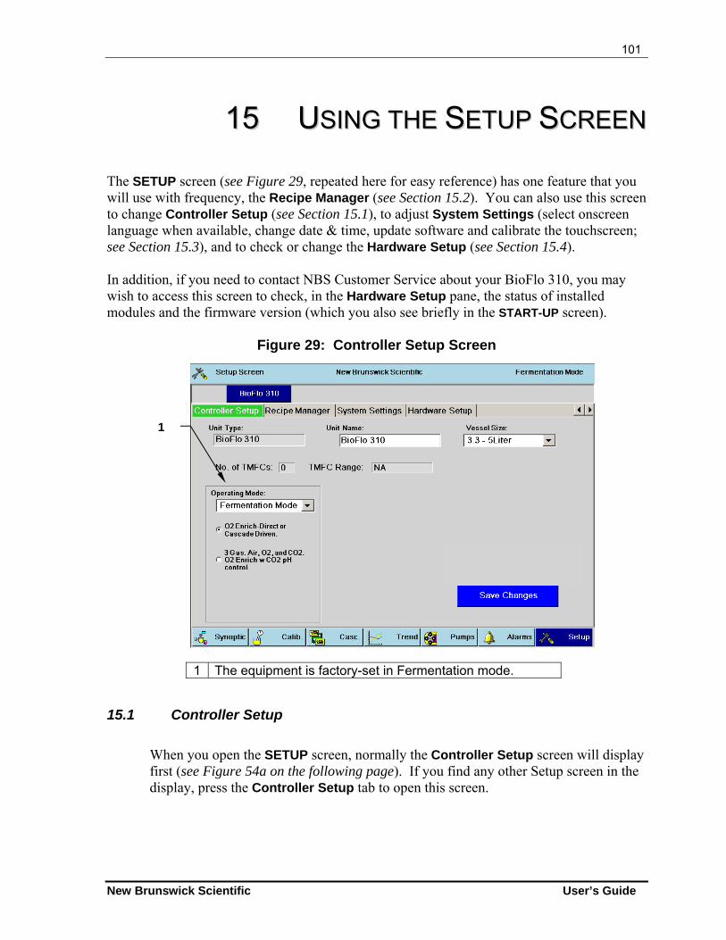
101
New Brunswick Scientific User’s Guide
1155 UUSSIINNGG TTHHEE SSEETTUUPP SSCCRREEEENN The SETUP screen (see Figure 29, repeated here for easy reference) has one feature that you will use with frequency, the Recipe Manager (see Section 15.2). You can also use this screen to change Controller Setup (see Section 15.1), to adjust System Settings (select onscreen language when available, change date & time, update software and calibrate the touchscreen; see Section 15.3), and to check or change the Hardware Setup (see Section 15.4). In addition, if you need to contact NBS Customer Service about your BioFlo 310, you may wish to access this screen to check, in the Hardware Setup pane, the status of installed modules and the firmware version (which you also see briefly in the START-UP screen).
Figure 29: Controller Setup Screen
1 The equipment is factory-set in Fermentation mode.
15.1 Controller Setup
When you open the SETUP screen, normally the Controller Setup screen will display first (see Figure 54a on the following page). If you find any other Setup screen in the display, press the Controller Setup tab to open this screen.
1
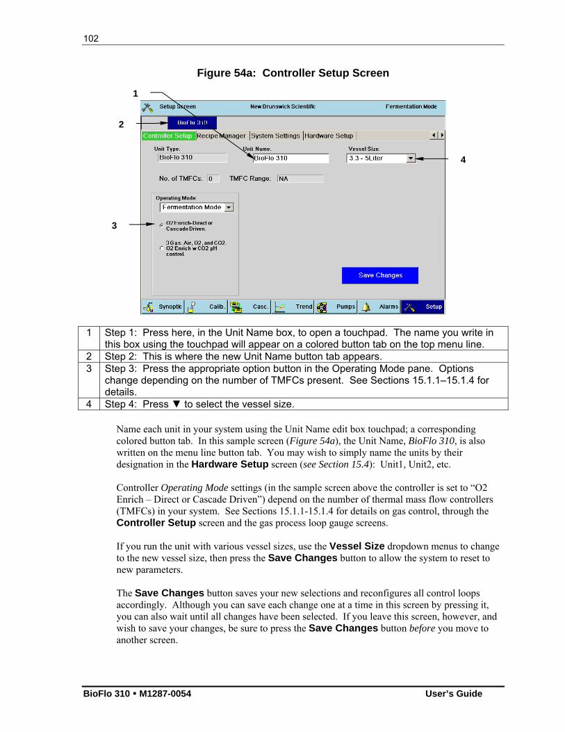
102
BioFlo 310 M1287-0054 User’s Guide
Figure 54a: Controller Setup Screen
1 Step 1: Press here, in the Unit Name box, to open a touchpad. The name you write in this box using the touchpad will appear on a colored button tab on the top menu line.
2 Step 2: This is where the new Unit Name button tab appears. 3 Step 3: Press the appropriate option button in the Operating Mode pane. Options
change depending on the number of TMFCs present. See Sections 15.1.1–15.1.4 for details.
4 Step 4: Press ▼ to select the vessel size. Name each unit in your system using the Unit Name edit box touchpad; a corresponding colored button tab. In this sample screen (Figure 54a), the Unit Name, BioFlo 310, is also written on the menu line button tab. You may wish to simply name the units by their designation in the Hardware Setup screen (see Section 15.4): Unit1, Unit2, etc. Controller Operating Mode settings (in the sample screen above the controller is set to “O2 Enrich – Direct or Cascade Driven”) depend on the number of thermal mass flow controllers (TMFCs) in your system. See Sections 15.1.1-15.1.4 for details on gas control, through the Controller Setup screen and the gas process loop gauge screens. If you run the unit with various vessel sizes, use the Vessel Size dropdown menus to change to the new vessel size, then press the Save Changes button to allow the system to reset to new parameters. The Save Changes button saves your new selections and reconfigures all control loops accordingly. Although you can save each change one at a time in this screen by pressing it, you can also wait until all changes have been selected. If you leave this screen, however, and wish to save your changes, be sure to press the Save Changes button before you move to another screen.
4
1
3
2
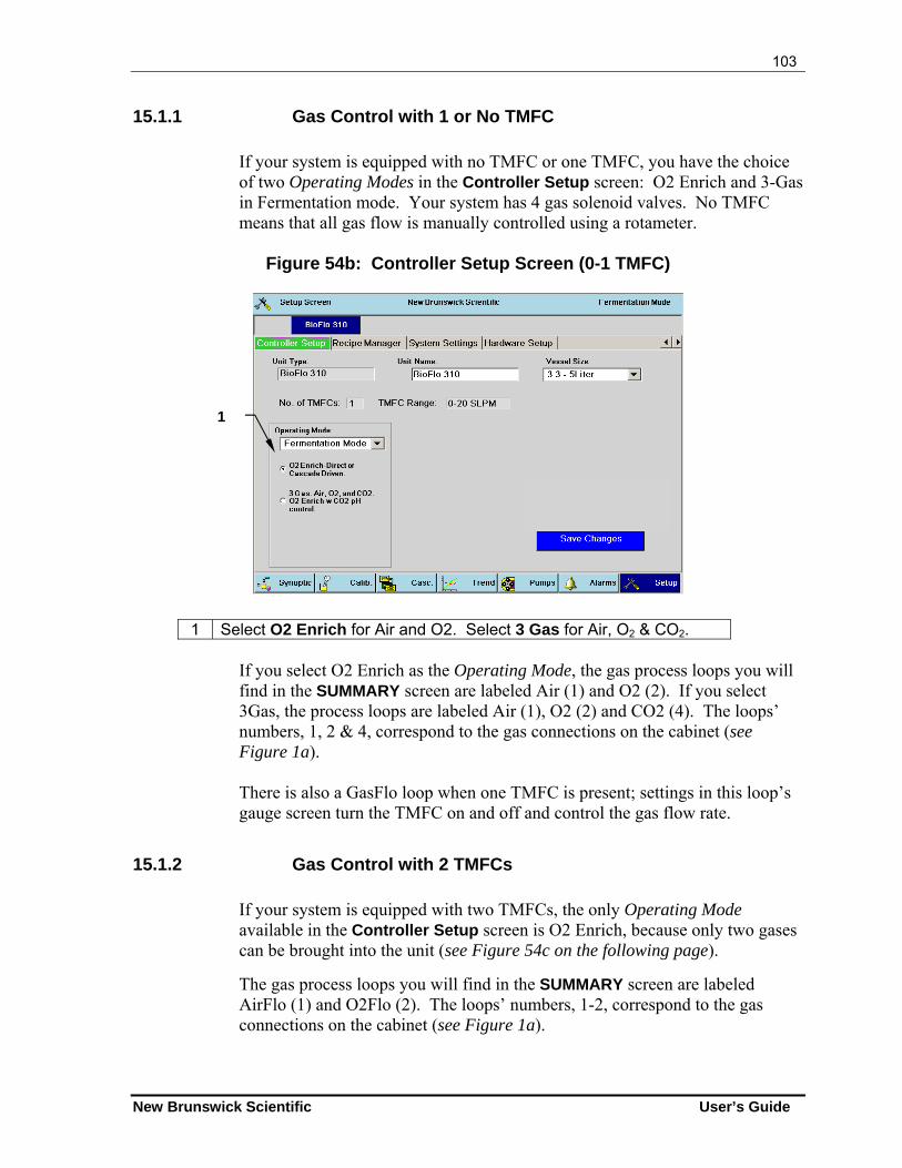
103
New Brunswick Scientific User’s Guide
15.1.1 Gas Control with 1 or No TMFC
If your system is equipped with no TMFC or one TMFC, you have the choice of two Operating Modes in the Controller Setup screen: O2 Enrich and 3-Gas in Fermentation mode. Your system has 4 gas solenoid valves. No TMFC means that all gas flow is manually controlled using a rotameter.
Figure 54b: Controller Setup Screen (0-1 TMFC)
1 Select O2 Enrich for Air and O2. Select 3 Gas for Air, O2 & CO2.
If you select O2 Enrich as the Operating Mode, the gas process loops you will find in the SUMMARY screen are labeled Air (1) and O2 (2). If you select 3Gas, the process loops are labeled Air (1), O2 (2) and CO2 (4). The loops’ numbers, 1, 2 & 4, correspond to the gas connections on the cabinet (see Figure 1a). There is also a GasFlo loop when one TMFC is present; settings in this loop’s gauge screen turn the TMFC on and off and control the gas flow rate.
15.1.2 Gas Control with 2 TMFCs
If your system is equipped with two TMFCs, the only Operating Mode available in the Controller Setup screen is O2 Enrich, because only two gases can be brought into the unit (see Figure 54c on the following page).
The gas process loops you will find in the SUMMARY screen are labeled AirFlo (1) and O2Flo (2). The loops’ numbers, 1-2, correspond to the gas connections on the cabinet (see Figure 1a).
1
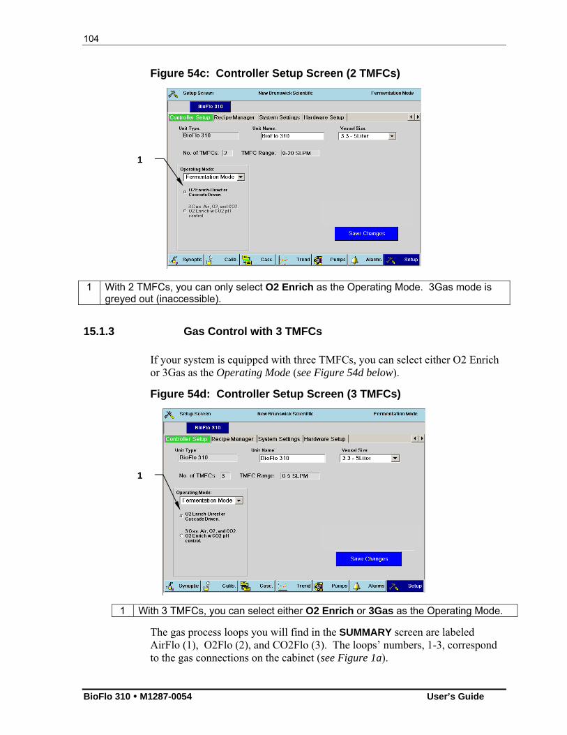
104
BioFlo 310 M1287-0054 User’s Guide
Figure 54c: Controller Setup Screen (2 TMFCs)
1 With 2 TMFCs, you can only select O2 Enrich as the Operating Mode. 3Gas mode is greyed out (inaccessible).
15.1.3 Gas Control with 3 TMFCs
If your system is equipped with three TMFCs, you can select either O2 Enrich or 3Gas as the Operating Mode (see Figure 54d below).
Figure 54d: Controller Setup Screen (3 TMFCs)
1 With 3 TMFCs, you can select either O2 Enrich or 3Gas as the Operating Mode.
The gas process loops you will find in the SUMMARY screen are labeled AirFlo (1), O2Flo (2), and CO2Flo (3). The loops’ numbers, 1-3, correspond to the gas connections on the cabinet (see Figure 1a).
1
1
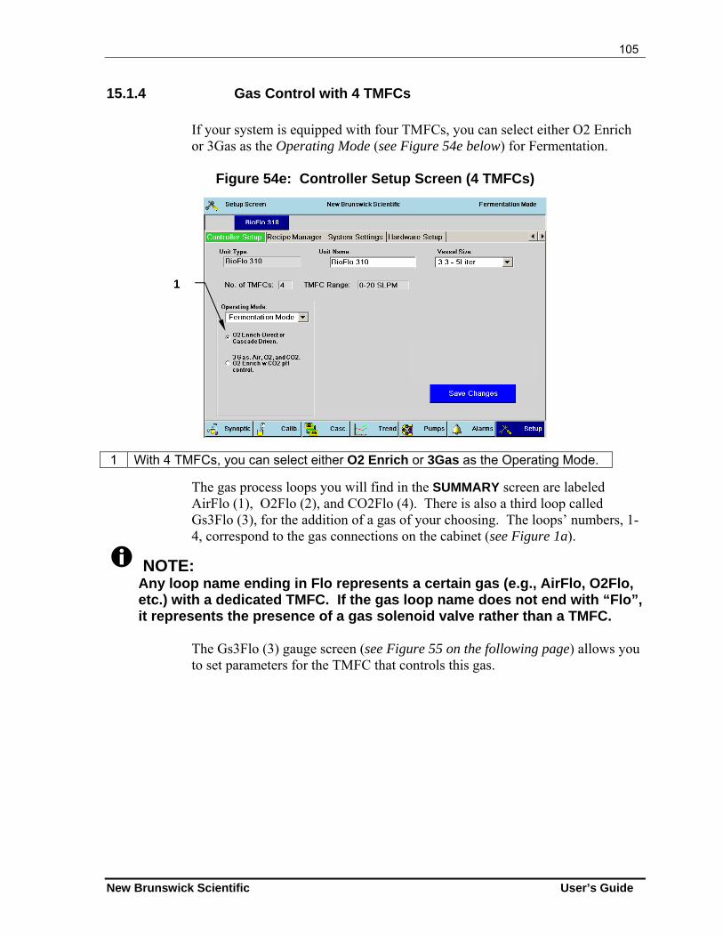
105
New Brunswick Scientific User’s Guide
15.1.4 Gas Control with 4 TMFCs
If your system is equipped with four TMFCs, you can select either O2 Enrich or 3Gas as the Operating Mode (see Figure 54e below) for Fermentation.
Figure 54e: Controller Setup Screen (4 TMFCs)
1 With 4 TMFCs, you can select either O2 Enrich or 3Gas as the Operating Mode.
The gas process loops you will find in the SUMMARY screen are labeled AirFlo (1), O2Flo (2), and CO2Flo (4). There is also a third loop called Gs3Flo (3), for the addition of a gas of your choosing. The loops’ numbers, 1-4, correspond to the gas connections on the cabinet (see Figure 1a).
NOTE: Any loop name ending in Flo represents a certain gas (e.g., AirFlo, O2Flo, etc.) with a dedicated TMFC. If the gas loop name does not end with “Flo”, it represents the presence of a gas solenoid valve rather than a TMFC.
The Gs3Flo (3) gauge screen (see Figure 55 on the following page) allows you to set parameters for the TMFC that controls this gas.
1
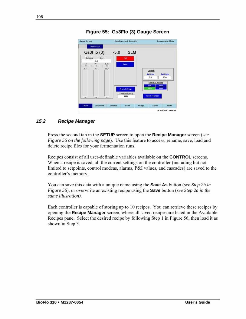
106
BioFlo 310 M1287-0054 User’s Guide
Figure 55: Gs3Flo (3) Gauge Screen
15.2 Recipe Manager
Press the second tab in the SETUP screen to open the Recipe Manager screen (see Figure 56 on the following page). Use this feature to access, rename, save, load and delete recipe files for your fermentation runs. Recipes consist of all user-definable variables available on the CONTROL screens. When a recipe is saved, all the current settings on the controller (including but not limited to setpoints, control modeas, alarms, P&I values, and cascades) are saved to the controller’s memory. You can save this data with a unique name using the Save As button (see Step 2b in Figure 56), or overwrite an existing recipe using the Save button (see Step 2a in the same illusration). Each controller is capable of storing up to 10 recipes. You can retrieve these recipes by opening the Recipe Manager screen, where all saved recipes are listed in the Available Recipes pane. Select the desired recipe by following Step 1 in Figure 56, then load it as shown in Step 3.
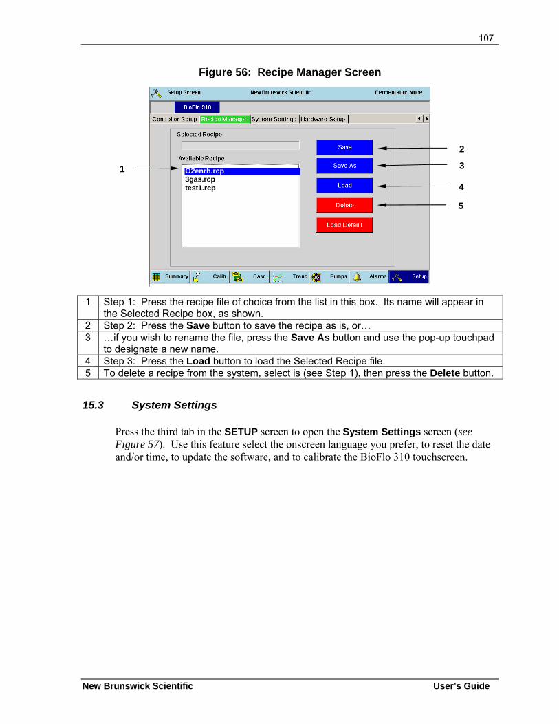
107
New Brunswick Scientific User’s Guide
Figure 56: Recipe Manager Screen
1 Step 1: Press the recipe file of choice from the list in this box. Its name will appear in the Selected Recipe box, as shown.
2 Step 2: Press the Save button to save the recipe as is, or… 3 …if you wish to rename the file, press the Save As button and use the pop-up touchpad
to designate a new name. 4 Step 3: Press the Load button to load the Selected Recipe file. 5 To delete a recipe from the system, select is (see Step 1), then press the Delete button.
15.3 System Settings
Press the third tab in the SETUP screen to open the System Settings screen (see Figure 57). Use this feature select the onscreen language you prefer, to reset the date and/or time, to update the software, and to calibrate the BioFlo 310 touchscreen.
O2enrh.rcp 3gas.rcp test1.rcp
1
4
3
2
5
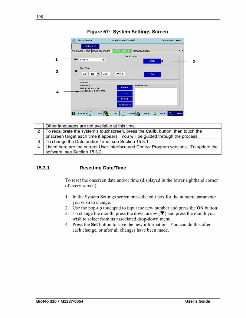
108
BioFlo 310 M1287-0054 User’s Guide
Figure 57: System Settings Screen
1 Other languages are not available at this time. 2 To recalibrate the system’s touchscreen, press the Calib. button, then touch the
onscreen target each time it appears. You will be guided through the process. 3 To change the Date and/or Time, see Section 15.3.1. 4 Listed here are the current User Interface and Control Program versions. To update the
software, see Section 15.3.2.
15.3.1 Resetting Date/Time
To reset the onscreen date and/or time (displayed in the lower righthand corner of every screen): 1. In the System Settings screen press the edit box for the numeric parameter
you wish to change. 2. Use the pop-up touchpad to input the new number and press the OK button. 3. To change the month, press the down arrow () and press the month you
wish to select from its associated drop-down menu. 4. Press the Set button to save the new information. You can do this after
each change, or after all changes have been made.
1
3
4
2
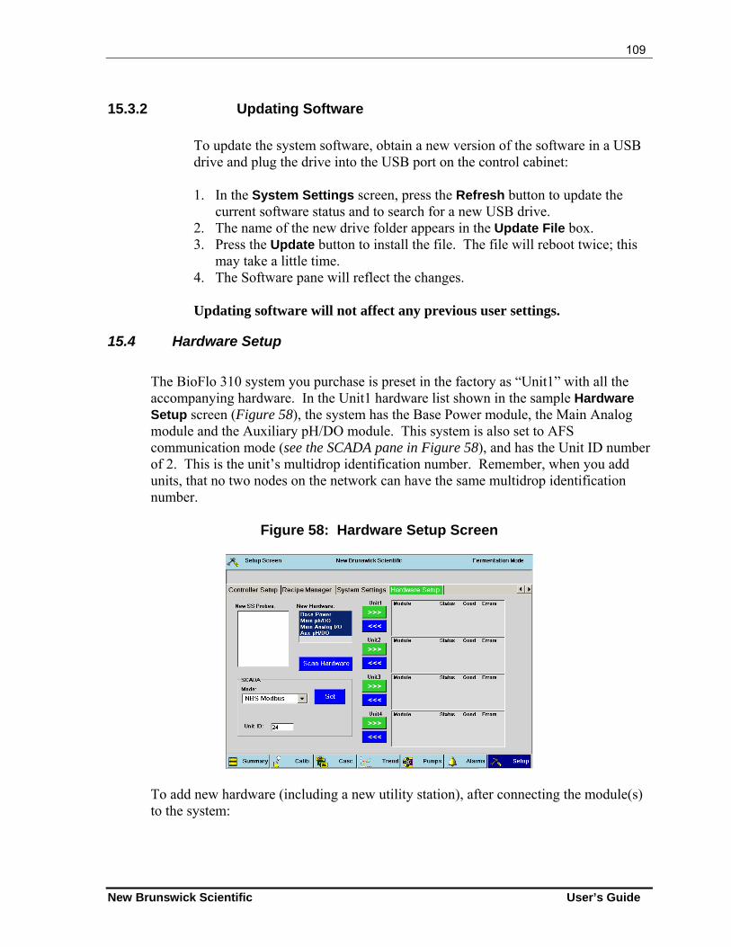
109
New Brunswick Scientific User’s Guide
15.3.2 Updating Software
To update the system software, obtain a new version of the software in a USB drive and plug the drive into the USB port on the control cabinet: 1. In the System Settings screen, press the Refresh button to update the
current software status and to search for a new USB drive. 2. The name of the new drive folder appears in the Update File box. 3. Press the Update button to install the file. The file will reboot twice; this
may take a little time. 4. The Software pane will reflect the changes. Updating software will not affect any previous user settings.
15.4 Hardware Setup
The BioFlo 310 system you purchase is preset in the factory as “Unit1” with all the accompanying hardware. In the Unit1 hardware list shown in the sample Hardware Setup screen (Figure 58), the system has the Base Power module, the Main Analog module and the Auxiliary pH/DO module. This system is also set to AFS communication mode (see the SCADA pane in Figure 58), and has the Unit ID number of 2. This is the unit’s multidrop identification number. Remember, when you add units, that no two nodes on the network can have the same multidrop identification number.
Figure 58: Hardware Setup Screen
To add new hardware (including a new utility station), after connecting the module(s) to the system:
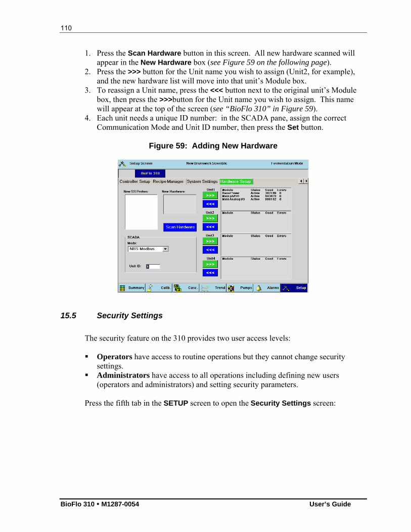
110
BioFlo 310 M1287-0054 User’s Guide
1. Press the Scan Hardware button in this screen. All new hardware scanned will appear in the New Hardware box (see Figure 59 on the following page).
2. Press the >>> button for the Unit name you wish to assign (Unit2, for example), and the new hardware list will move into that unit’s Module box.
3. To reassign a Unit name, press the <<< button next to the original unit’s Module box, then press the >>>button for the Unit name you wish to assign. This name will appear at the top of the screen (see “BioFlo 310” in Figure 59).
4. Each unit needs a unique ID number: in the SCADA pane, assign the correct Communication Mode and Unit ID number, then press the Set button.
Figure 59: Adding New Hardware
15.5 Security Settings
The security feature on the 310 provides two user access levels:
Operators have access to routine operations but they cannot change security
settings. Administrators have access to all operations including defining new users
(operators and administrators) and setting security parameters.
Press the fifth tab in the SETUP screen to open the Security Settings screen:
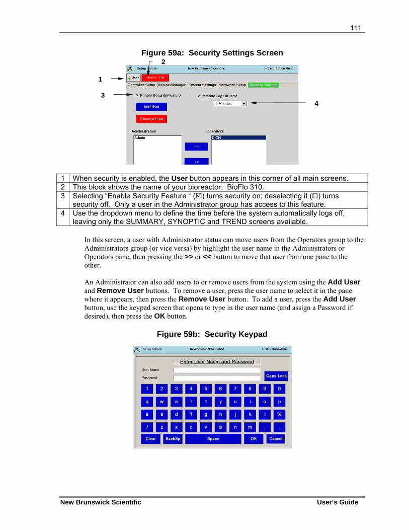
111
New Brunswick Scientific User’s Guide
Figure 59a: Security Settings Screen
1 When security is enabled, the User button appears in this corner of all main screens. 2 This block shows the name of your bioreactor: BioFlo 310. 3 Selecting “Enable Security Feature “ () turns security on; deselecting it () turns
security off. Only a user in the Administrator group has access to this feature. 4 Use the dropdown menu to define the time before the system automatically logs off,
leaving only the SUMMARY, SYNOPTIC and TREND screens available. In this screen, a user with Administrator status can move users from the Operators group to the Administrators group (or vice versa) by highlight the user name in the Administrators or Operators pane, then pressing the >> or << button to move that user from one pane to the other.
An Administrator can also add users to or remove users from the system using the Add User and Remove User buttons. To remove a user, press the user name to select it in the pane where it appears, then press the Remove User button. To add a user, press the Add User button, use the keypad screen that opens to type in the user name (and assign a Password if desired), then press the OK button.
Figure 59b: Security Keypad
1
3 4
2
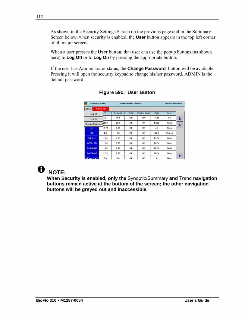
112
BioFlo 310 M1287-0054 User’s Guide
As shown in the Security Settings Screen on the previous page and in the Summary Screen below, when security is enabled, the User button appears in the top left corner of all major screens.
When a user presses the User button, that user can use the popup buttons (as shown here) to Log Off or to Log On by pressing the appropriate button. If the user has Administrator status, the Change Password button will be available. Pressing it will open the security keypad to change his/her password. ADMIN is the default password.
Figure 59c: User Button
NOTE: When Security is enabled, only the Synoptic/Summary and Trend navigation buttons remain active at the bottom of the screen; the other navigation buttons will be greyed out and inaccessible.
113
New Brunswick Scientific User’s Guide
1166 PPEERRFFOORRMMIINNGG AA RRUUNN
16.1 Set Up Foam Control
Before you fill the vessel with medium, confirm that the foam probe is working properly:
1. Fill the vessel with tap water or saline solution. DO NOT USE DISTILLED
WATER: an ionic solution is necessary for conductivity. 2. Fill an addition bottle with the antifoam you will use. Attach small bore tubing to
the bottle. Plug the end with cotton, and wrap the cotton with aluminum foil. Autoclave the bottle and tubing.
3. Thread the tubing through the pump, then aseptically connect the tubing to the headplate antifoam addition port.
4. Turn the pump on to prime the line. 5. Install the foam probe in its headplate port. 6. Connect the foam probe cable to Lvl 1 on the control cabinet, then attach the cable
to the foam probe. Attach the ground. 7. Open the PUMPS screen. 8. Select the feed pump you are using by assigning Foam to that pump. 9. Enter the pump setpoint and press the ON button. 10. Remove the water/saline solution from the vessel. 11. Add medium to the vessel. 12. Ensure that all appropriate sensors and feed/harvest tubes, including the foam
probe and antifoam addition system, are properly inserted and secure. 13. Make sure the DO probe and the pH probe are capped. 14. Ensure that the temperature probe is not in the thermowell; it cannot be autoclaved. 15. Close off all connectors with cotton and aluminum foil, clamp off all tubing, and
autoclave the entire assembly. 16. After the vessel has cooled, connect all probes to the control cabinet and all
addition tubes to the appropriate pumps. Make sure that all harvest and sample tubes are at the right level.
17. Make sure the impeller shaft is correctly and completely seated into the bearing housing.
18. Make sure that any unused ports are plugged with the supplied penetration plugs.
16.2 Preparing for a Fermentation Run
1. Connect water to the unit and turn it on. 2. Make sure the drain line is properly connected to the unit. 3. Connect the quick-connect plastic water lines to the vessel jacket and exhaust
condenser.

114
BioFlo 310 M1287-0054 User’s Guide
CAUTION! Before connecting or disconnecting the water hoses to/from the vessel at any time, be sure to follow these instructions in the order indicated: To connect: (1) Connect vessel Water Out line, (2) Connect vessel Water In line, (3) Connect cabinet Main Water In line, (4) Turn ON main power switch on cabinet. To disconnect: (1) Turn OFF main power switch on cabinet, (2) Disconnect Main Water In line from cabinet, (3) Disconnect vessel Water In line,
(4) Disconnect vessel Water Out line. Failure to heed these instructions may lead to hose leakage and/or pressure build-up inside the vessel jacket.
4. Add glycerin to the thermowell and insert the temperature probe. 5. Make sure the motor is not connected. Turn the power ON. 6. Set the TEMP loop sepoint below the ambient temperature and select Auto as the
TEMP control mode. This will prime the water jacket. 7. Set the TEMP setpoint to the desired working temperature. 8. Check that agitation (Agit) is in OFF mode. Connect the motor, then set agitation
to the desired speed, and select Auto as its control mode. 9. Remove the shorting cap from the pH probe. Connect the pH cable to the pH
probe. 10. Remove the protective cap from the DO probe and connect the DO cable to the DO
probe.
NOTE: The DO polarographic probe will need to be connected for a minimum of six hours, to be properly polarized, before it can be correctly calibrated.
11. Calibrate the DO probe (see Section Error! Reference source not found.). 12. Set pH and DO to the desired setpoints 13. Set the pH control mode to Auto. 14. Set the DO control mode to Auto. 15. Open the PUMPS screen and assign a pump to Acid and another pump to Base.
Turn the pumps ON. 16. If you are using oxygen, set the O2 control loop to the desired setpoint for oxygen
enrichment. If, however, you are using Air only, set the O2 setpoint to 0 (zero). 17. Set the O2 (or Air) control loop control mode to O2 Enrich. 18. Open the CASCADE screen and select the pH loop. 19. Enable the pumps. 20. Return to the CASCADE screen and select the DO loop. 21. Set up cascades for Agit, GasFlow (if your unit has automatic thermal mass flow
control) and O2. You can also cascade a pump for glucose addition. 22. Enable the cascades.
115
New Brunswick Scientific User’s Guide
23. Set the GasFlow loop’s control mode to ON.
NOTE:
Aeration is required whenever the agitation setpoint is greater than 750 RPM. NBS suggests a minimum airflow rate of 0.25 VVM when running at speeds 750 RPM.
16.3 Inoculation
Using the septum port: 1. Aseptically remove the inoculum from its flask with the inoculation syringe. 2. Inject the inoculum through the septum in the inoculation port.
If you prefer to inoculate via an addition port, be sure to flame the connectors and use an inoculum flask as your “addition vessel” (see Figure 39 for reference).
16.4 Start BioCommand (if present)
1. Start the BioCommand supervisory software on your computer, reset the EFT
(Elapsed Fermentation Time) to zero, make appropriate program selections to begin logging data.
2. Make sure all gas pressures are 10 PSI and the water pressure is 10 PSI. 3. If your BioFlo 310 has rotameter air flow control, adjust the airflow to the desired
rate. Check to see that flow is stable and that all gases are properly connected.
16.5 Sampling Procedure
Referring to Figure 10 or 11, whichever represents your sampling system:
1. Check to be sure that the sample bottle is slightly loose, not tight against the gasket.
2. Close the valve on the sampler tube, if it is open. 3. Squeeze the bulb and, holding it compressed, tighten the sample bottle against the
gasket. 4. Open the valve and gradually let go of the rubber bulb to obtain the desired sample
volume. 5. When you have obtained the desire volume, close the valve. 6. Unscrew the sample bottle from the sampler. Take the cap from a new bottle, and
place it on the sample-filled bottle. 7. Install the new bottle in the sampler and make sure that the sample bottle is firmly
sealed against the sampler gasket. Always use aseptic techniques. 8. Repeat the above steps until you have the desired number of samples.
116
BioFlo 310 M1287-0054 User’s Guide
16.6 Fermentation Phases
In a typical fermentation run, you can expect to see four characteristic phases: (1) the Lag phase, (2) the Exponential Growth phase, (3) the Steady State phase, and (4) the Decline phase.
16.6.1 Lag Phase
This initial phase is aptly named because it is the slow beginning of your fermentation run, while the microbes become accustomed to their medium.
16.6.2 Exponential Growth Phase
After the initial lag, a sudden spurt in growth will indicate that the environment is fully hospitable to the microbes. Compared to the nearly inanimate lag phase, this activity will appear to be nearly uncontrolled.
16.6.3 Steady State Phase Most of your run will be the desired steady state of growth. As long as the temperature, pH, DO and other essential parameters are stable and you feed your batch appropriately, this phase can last, for a standard e.coli fermentation, for example, approximately 2-3 hours. Eventually, however, you must expect your batch to decline.
16.6.4 Decline Phase
This final phase is marked by a slow dying off, which is, of course, inevitable.
16.7 Batch Operation
A batch operation is a closed growth environment in the sense that it contains a finite amount of media. The inoculum grows through the various phases of fermentation until it begins to decline and you harvest the desired product. It is easy to run and yields results quickly.
16.8 Fed Batch Operation
A fed batch operation (see Figure 60 on the following page) includes the addition of media to feed the batch fresh nutrient and to dilute any build-up of toxic by-products in the broth, thereby extending the life and growth of the desired product. (See also Figure 39.)
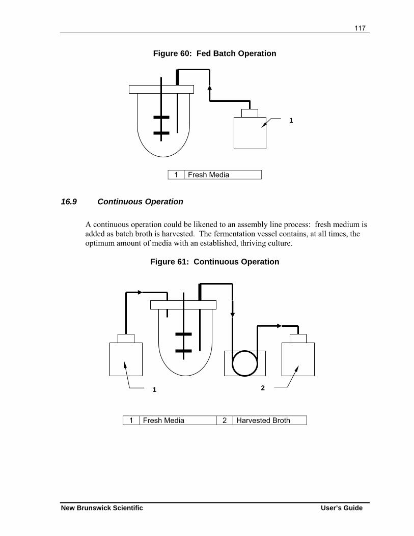
117
New Brunswick Scientific User’s Guide
Figure 60: Fed Batch Operation
1 Fresh Media
16.9 Continuous Operation
A continuous operation could be likened to an assembly line process: fresh medium is added as batch broth is harvested. The fermentation vessel contains, at all times, the optimum amount of media with an established, thriving culture.
Figure 61: Continuous Operation
1 Fresh Media 2 Harvested Broth
1
1 2
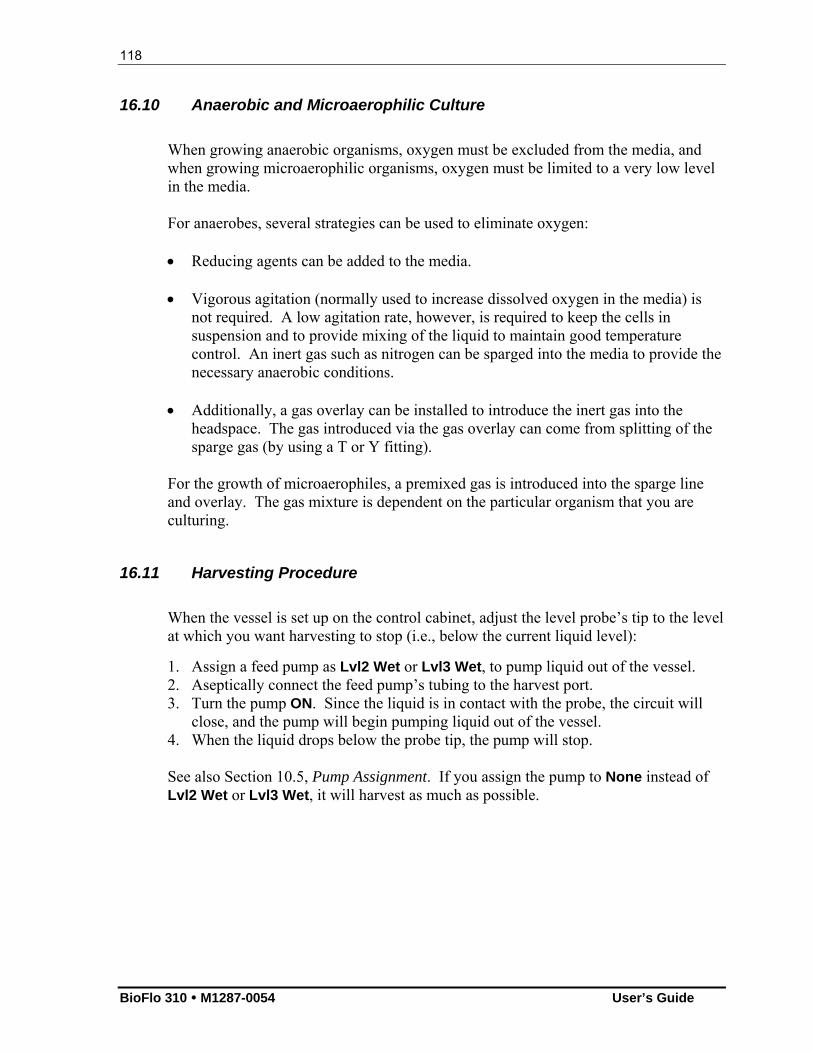
118
BioFlo 310 M1287-0054 User’s Guide
16.10 Anaerobic and Microaerophilic Culture
When growing anaerobic organisms, oxygen must be excluded from the media, and when growing microaerophilic organisms, oxygen must be limited to a very low level in the media. For anaerobes, several strategies can be used to eliminate oxygen: Reducing agents can be added to the media.
Vigorous agitation (normally used to increase dissolved oxygen in the media) is
not required. A low agitation rate, however, is required to keep the cells in suspension and to provide mixing of the liquid to maintain good temperature control. An inert gas such as nitrogen can be sparged into the media to provide the necessary anaerobic conditions.
Additionally, a gas overlay can be installed to introduce the inert gas into the headspace. The gas introduced via the gas overlay can come from splitting of the sparge gas (by using a T or Y fitting).
For the growth of microaerophiles, a premixed gas is introduced into the sparge line and overlay. The gas mixture is dependent on the particular organism that you are culturing.
16.11 Harvesting Procedure
When the vessel is set up on the control cabinet, adjust the level probe’s tip to the level at which you want harvesting to stop (i.e., below the current liquid level):
1. Assign a feed pump as Lvl2 Wet or Lvl3 Wet, to pump liquid out of the vessel. 2. Aseptically connect the feed pump’s tubing to the harvest port. 3. Turn the pump ON. Since the liquid is in contact with the probe, the circuit will
close, and the pump will begin pumping liquid out of the vessel. 4. When the liquid drops below the probe tip, the pump will stop.
See also Section 10.5, Pump Assignment. If you assign the pump to None instead of Lvl2 Wet or Lvl3 Wet, it will harvest as much as possible.
119
New Brunswick Scientific User’s Guide
16.12 Shutdown Procedure
At the end of a run, to shut down the system, follow these steps:
1. Set GasFlow to OFF. 2. Set Agit and Temp to OFF. 3. Set all other control loops to OFF. 4. Turn off the power. 5. If the system is not to be used for several days, disconnect the power plug. 6. Remove, drain and clean the vessel as outlined in Section 18.
See also Section 25.7.5 for shutdown and cleaning tips.NOTE:
Never wash the filters or get them wet.
120
BioFlo 310 M1287-0054 User’s Guide
1177 EESSSSEENNTTIIAALL OOPPEERRAATTIINNGG TTIIPPSS
17.1 Precautions for Glass Vessel Assembly
There are certain precautions you should take to avoid cracking or breaking the glass vessel during assembly and autoclaving:
Glass can crack or break during assembly if the clamping screws are
overtightened. As a precaution, tighten the screws only finger tight prior to autoclaving. You should be able to insert a business card between the glass and the metal.
If the vessel is not sufficiently vented during autoclaving, it can crack or break. As
a precaution, make certain that the exhaust filter(s) is (are) not wet or clogged. Also loosen the inoculation diaphragm cap for additional venting.
After autoclaving, tighten the inoculation cap. When the vessel is installed on the
control cabinet and air is freely flowing through it, you may retighten all nuts and screws, again taking care not to overtighten.
NOTE: To maintain the best possible seal, O-rings should be replaced every six months or more frequently if needed.
17.2 Exhaust Condenser & Exhaust Filters
The inner assembly of the exhaust condenser can be removed for cleaning:
1. Pass warm water and detergent through the top of the condenser, but not through
the quick-connects. Do this twice. 2. Run clear water through once. 3. Blow out with air. 4. Autoclave.
Clean the exhaust condenser after each run. This is most critical when operating as a chemostat for protracted fermentation times.
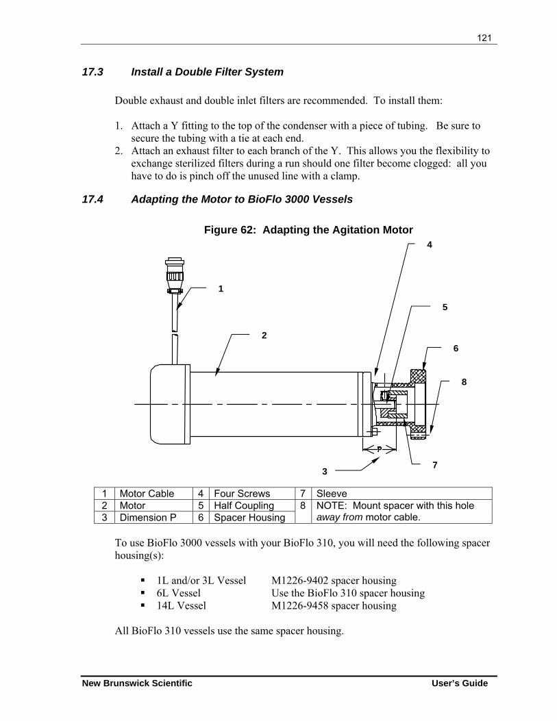
121
New Brunswick Scientific User’s Guide
17.3 Install a Double Filter System
Double exhaust and double inlet filters are recommended. To install them:
1. Attach a Y fitting to the top of the condenser with a piece of tubing. Be sure to
secure the tubing with a tie at each end. 2. Attach an exhaust filter to each branch of the Y. This allows you the flexibility to
exchange sterilized filters during a run should one filter become clogged: all you have to do is pinch off the unused line with a clamp.
17.4 Adapting the Motor to BioFlo 3000 Vessels
Figure 62: Adapting the Agitation Motor
1 Motor Cable 4 Four Screws 7 Sleeve 2 Motor 5 Half Coupling 3 Dimension P 6 Spacer Housing
8 NOTE: Mount spacer with this hole away from motor cable.
To use BioFlo 3000 vessels with your BioFlo 310, you will need the following spacer housing(s):
1L and/or 3L Vessel M1226-9402 spacer housing 6L Vessel Use the BioFlo 310 spacer housing 14L Vessel M1226-9458 spacer housing
All BioFlo 310 vessels use the same spacer housing.
1
2
4
6
7
5
8
3
122
BioFlo 310 M1287-0054 User’s Guide
1188 CCLLEEAANNIINNGG
CAUTION! To avoid leaks and/or pressure build-up inside the vessel jacket, see CAUTION regarding connecting & disconnecting hoses in Section 4.8.2.
CAUTION! Never clean the vessel or its components or the control cabinet with abrasive chemicals or materials.
18.1 Cleaning the Vessel
NOTE: If applicable, be sure to follow the bio-safety regulations regarding the release of microorganisms into the environment.
1. Fill the vessel with a mild detergent and water solution. 2. Let it stand for one hour, then brush it thoroughly with a soft brush. Use the brush
both on inside and on outside surfaces. 3. Drain the vessel and rinse several times with tap water. 4. Repeat rinsing with distilled water and let it dry.
18.1.1 List of Wetted Parts
For further reference in your choice of cleaning detergents, Table 8 provides a list of wetted parts in the vessel assembly and the materials they are made of:
Table 8: Wetted Parts
Wetted Parts Material Purple headplate O-ring EPDM O-ring lubricant Silicone Headplate penetration O-rings EPDM Metal surfaces 316L or 316 stainless steel Vessel glass Borosilicate glass Inoculation septum Pure gum rubber, color tan

123
New Brunswick Scientific User’s Guide
18.2 Cleaning the Cabinet
At least once a month, clean all the metal parts of your unit. Use a soft, damp cloth moistened with water or mild detergent. If a detergent is used, remove all residue by rinsing them with clean water.
124
BioFlo 310 M1287-0054 User’s Guide
1199 MMAAIINNTTEENNAANNCCEE Preventive maintenance keeps your equipment in proper working condition. When performed routinely, maintenance results in longer life for your equipment. It also reduces time lost due to equipment failure.
WARNING! Always turn your BioFlo 310 off and disconnect the power cord before performing maintenance.
19.1 pH Probe Maintenance and Storage
The pH probe should be stored standing upright, with the electrode tip immersed in a solution of 3 molar KCl or a buffer solution between pH 4.00 and pH 7.00.
CAUTION! Never let a pH probe rest on its tip. Never leave a pH probe in DI water.
19.2 DO Probe Maintenance and Storage
Use soft facial tissue to clean the DO probe.
Check the probe’s Teflon membrane to be sure there are no punctures, puckers or wrinkles. If there are, the probe should be replaced.
When it is not in use in the vessel, the DO probe should be stored standing upright with the shorting cap in place and the membrane isolated from the air environment. At no time should the probe be allowed to rest on its membrane.
CAUTION! Never let a DO probe rest on its tip.
125
New Brunswick Scientific User’s Guide
19.3 Vessel & Tubing
After each and every run, clean the vessel and the headplate with its associated parts. All tubing and filters should be replaced.
19.4 Periodic Inspection
At three-month intervals, perform the following checks and inspections.
NOTE: Before you begin, make sure that the power switch is in the OFF position and that the power supply has been disconnected.
1. Check all controls and accessible items (power switch, connectors, screws, nuts
and bolts) to make sure they are properly tightened. Tighten any loose item(s). 2. Check that all controls and connectors are free of dust. 3. Check that all O-rings in the headplate and impellers are intact and in good
condition. Replace those that are not.
19.5 Agitator Bearing Housing
Every 3-6 months, the ball bearings and the shaft seals in the bearing housing should be checked and cleaned. Replace any worn-out bearings and/or shaft seals.
19.5.1 Motor Assembly Replacement
WARNING! NO ONE BUT A PROFESSIONAL SERVICE PERSON should touch electric or electronic parts or assemblies in the control cabinet.
If the motor assembly should require replacement, call for an authorized NBS service technician.
19.6 Fuse Replacement
There is one replaceable 5-Amp fast-acting glass tube fuse.
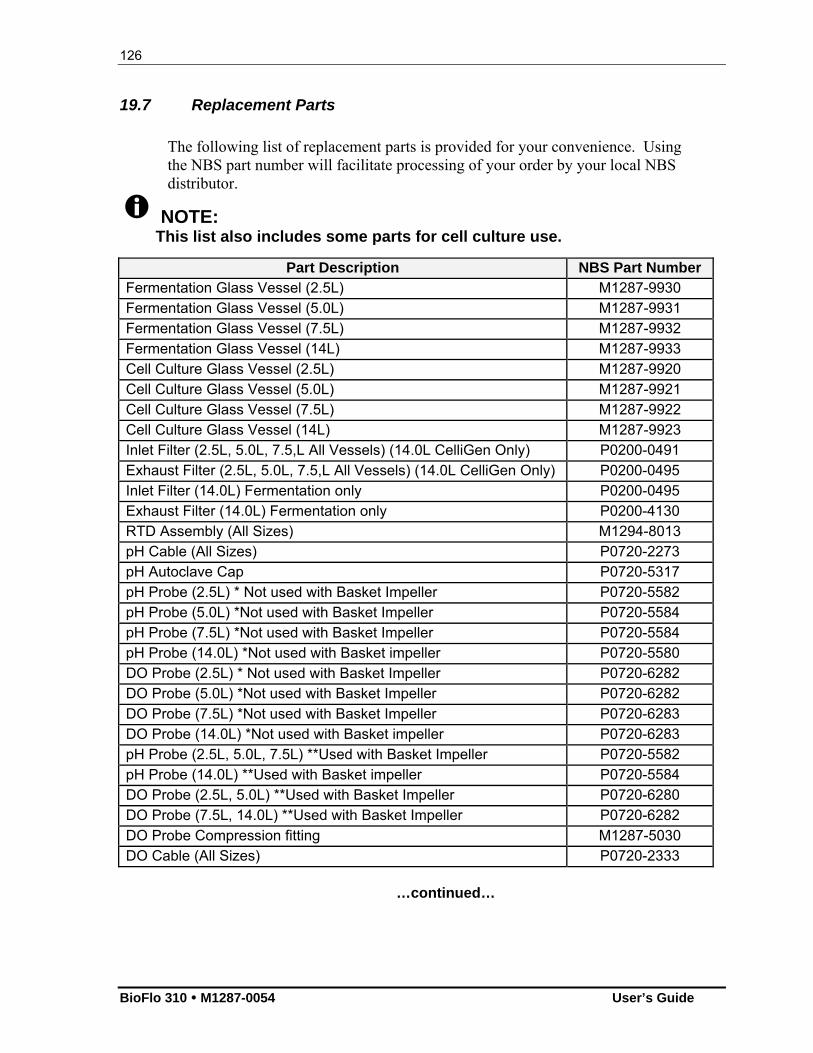
126
BioFlo 310 M1287-0054 User’s Guide
19.7 Replacement Parts
The following list of replacement parts is provided for your convenience. Using the NBS part number will facilitate processing of your order by your local NBS distributor.
NOTE: This list also includes some parts for cell culture use.
Part Description NBS Part Number Fermentation Glass Vessel (2.5L) M1287-9930 Fermentation Glass Vessel (5.0L) M1287-9931 Fermentation Glass Vessel (7.5L) M1287-9932 Fermentation Glass Vessel (14L) M1287-9933 Cell Culture Glass Vessel (2.5L) M1287-9920 Cell Culture Glass Vessel (5.0L) M1287-9921 Cell Culture Glass Vessel (7.5L) M1287-9922 Cell Culture Glass Vessel (14L) M1287-9923 Inlet Filter (2.5L, 5.0L, 7.5,L All Vessels) (14.0L CelliGen Only) P0200-0491 Exhaust Filter (2.5L, 5.0L, 7.5,L All Vessels) (14.0L CelliGen Only) P0200-0495 Inlet Filter (14.0L) Fermentation only P0200-0495 Exhaust Filter (14.0L) Fermentation only P0200-4130 RTD Assembly (All Sizes) M1294-8013 pH Cable (All Sizes) P0720-2273 pH Autoclave Cap P0720-5317 pH Probe (2.5L) * Not used with Basket Impeller P0720-5582 pH Probe (5.0L) *Not used with Basket Impeller P0720-5584 pH Probe (7.5L) *Not used with Basket Impeller P0720-5584 pH Probe (14.0L) *Not used with Basket impeller P0720-5580 DO Probe (2.5L) * Not used with Basket Impeller P0720-6282 DO Probe (5.0L) *Not used with Basket Impeller P0720-6282 DO Probe (7.5L) *Not used with Basket Impeller P0720-6283 DO Probe (14.0L) *Not used with Basket impeller P0720-6283 pH Probe (2.5L, 5.0L, 7.5L) **Used with Basket Impeller P0720-5582 pH Probe (14.0L) **Used with Basket impeller P0720-5584 DO Probe (2.5L, 5.0L) **Used with Basket Impeller P0720-6280 DO Probe (7.5L, 14.0L) **Used with Basket Impeller P0720-6282 DO Probe Compression fitting M1287-5030 DO Cable (All Sizes) P0720-2333
…continued…
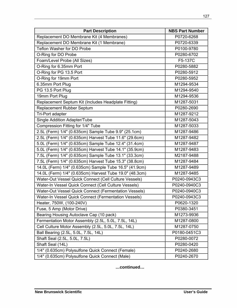
127
New Brunswick Scientific User’s Guide
Part Description NBS Part Number Replacement DO Membrane Kit (4 Membranes) P0720-6268 Replacement DO Membrane Kit (1 Membrane) P0720-6339 Teflon Washer for DO Probe P0100-9780 O-Ring for DO Probe P0280-6702 Foam/Level Probe (All Sizes) F5-137C O-Ring for 6.35mm Port P0280-5882 O-Ring for PG 13.5 Port P0280-5912 O-Ring for 19mm Port P0280-5952 6.35mm Port Plug M1294-9534 PG 13.5 Port Plug M1294-9540 19mm Port Plug M1294-9536 Replacement Septum Kit (Includes Headplate Fitting) M1287-5031 Replacement Rubber Septum P0280-2690 Tri-Port adapter M1287-9212 Single Addition Adapter/Tube M1287-5043 Compression Fitting for 1/4" Tube M1287-5033 2.5L (Ferm) 1/4" (0.635cm) Sample Tube 9.9" (25.1cm) M1287-9486 2.5L (Ferm) 1/4" (0.635cm) Harvest Tube 11.6" (29.6cm) M1287-9482 5.0L (Ferm) 1/4" (0.635cm) Sample Tube 12.4" (31.4cm) M1287-9487 5.0L (Ferm) 1/4" (0.635cm) Harvest Tube 14.1" (35.9cm) M1287-9483 7.5L (Ferm) 1/4" (0.635cm) Sample Tube 13.1" (33.3cm) M2187-9488 7.5L (Ferm) 1/4" (0.635cm) Harvest Tube 15.3" (38.8cm) M1287-9484 14.0L (Ferm) 1/4" (0.635cm) Sample Tube 16.5" (41.9cm) M1287-9489 14.0L (Ferm) 1/4" (0.635cm) Harvest Tube 19.0" (48.3cm) M1287-9485 Water-Out Vessel Quick Connect (Cell Culture Vessels) P0240-0943C3 Water-In Vessel Quick Connect (Cell Culture Vessels) P0240-0940C3 Water-Out Vessel Quick Connect (Fermentation Vessels) P0240-0940C3 Water-In Vessel Quick Connect (Fermentation Vessels) P0240-0943C3 Heater, 750W, (100-240V) P0620-1320 Fuse, 5 Amp (Motor Drive) P0380-3451 Bearing Housing Autoclave Cap (10 pack) M1273-9936 Fermentation Motor Assembly (2.5L, 5.0L, 7.5L, 14L) M1287-0800 Cell Culture Motor Assembly (2.5L, 5.0L, 7.5L, 14L) M1287-0750 Ball Bearing (2.5L, 5.0L, 7.5L, 14L) P0180-0451C3 Shaft Seal (2.5L, 5.0L, 7.5L) P0280-0072 Shaft Seal (14L) P0280-0420 1/4" (0.635cm) Polysulfone Quick Connect (Female) P0240-2680 1/4" (0.635cm) Polysulfone Quick Connect (Male) P0240-2670
…continued…

128
BioFlo 310 M1287-0054 User’s Guide
Part Description NBS Part Number 250mL Addition Bottle M1273-9989 500mL Addition Bottle M1273-9990 3/16" ID Silicone Tubing (25' Length) M0740-2505 1/8" ID Silicone Tubing (25' Length) M0740-2445 Replacement Headplate Thumb Screws M1287-9466 Silicone Grease (FDA Approved) P0860-1050
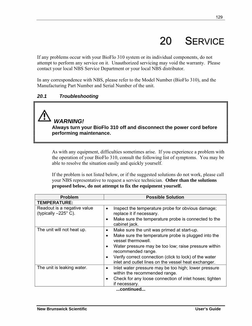
129
New Brunswick Scientific User’s Guide
2200 SSEERRVVIICCEE If any problems occur with your BioFlo 310 system or its individual components, do not attempt to perform any service on it. Unauthorized servicing may void the warranty. Please contact your local NBS Service Department or your local NBS distributor. In any correspondence with NBS, please refer to the Model Number (BioFlo 310), and the Manufacturing Part Number and Serial Number of the unit.
20.1 Troubleshooting
WARNING! Always turn your BioFlo 310 off and disconnect the power cord before performing maintenance.
As with any equipment, difficulties sometimes arise. If you experience a problem with the operation of your BioFlo 310, consult the following list of symptoms. You may be able to resolve the situation easily and quickly yourself. If the problem is not listed below, or if the suggested solutions do not work, please call your NBS representative to request a service technician. Other than the solutions proposed below, do not attempt to fix the equipment yourself.
Problem Possible Solution
TEMPERATURE: Readout is a negative value (typically –225° C).
Inspect the temperature probe for obvious damage; replace it if necessary.
Make sure the temperature probe is connected to the cabinet jack.
The unit will not heat up. Make sure the unit was primed at start-up. Make sure the temperature probe is plugged into the
vessel thermowell. Water pressure may be too low; raise pressure within
recommended range. Verify correct connection (click to lock) of the water
inlet and outlet lines on the vessel heat exchanger. The unit is leaking water. Inlet water pressure may be too high; lower pressure
within the recommended range. Check for any loose connection of inlet hoses; tighten
if necessary. ...continued...
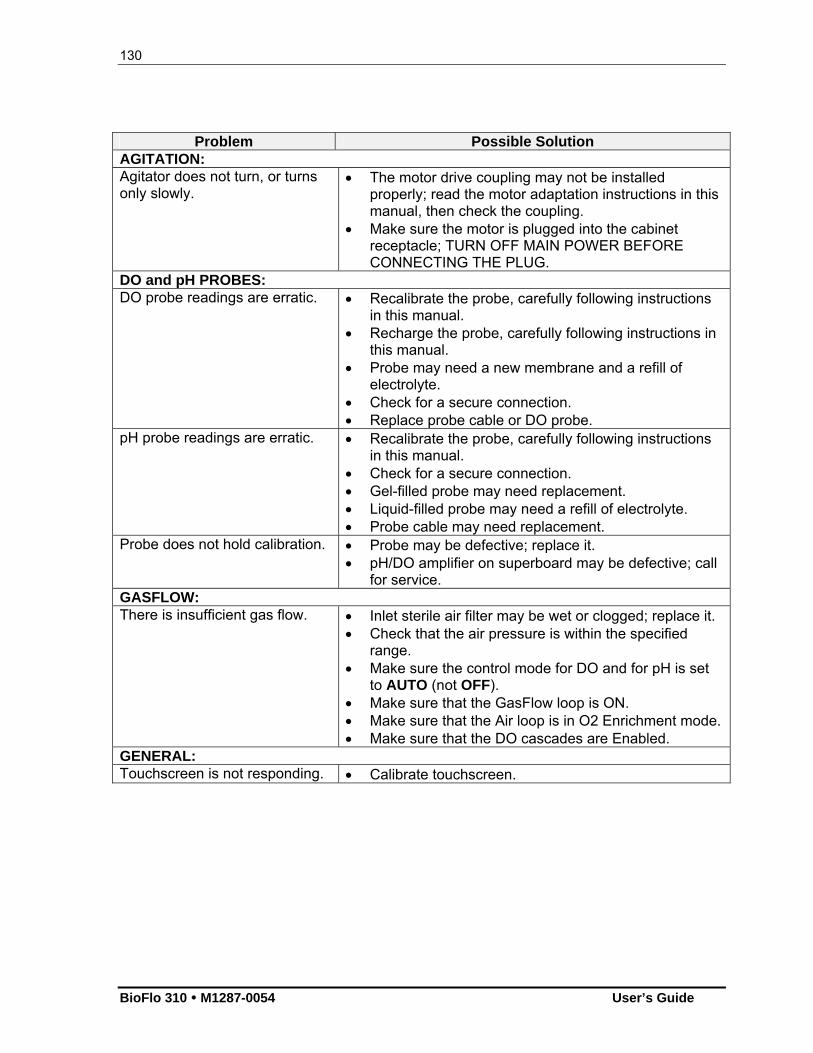
130
BioFlo 310 M1287-0054 User’s Guide
Problem Possible Solution AGITATION: Agitator does not turn, or turns only slowly.
The motor drive coupling may not be installed properly; read the motor adaptation instructions in this manual, then check the coupling.
Make sure the motor is plugged into the cabinet receptacle; TURN OFF MAIN POWER BEFORE CONNECTING THE PLUG.
DO and pH PROBES: DO probe readings are erratic. Recalibrate the probe, carefully following instructions
in this manual. Recharge the probe, carefully following instructions in
this manual. Probe may need a new membrane and a refill of
electrolyte. Check for a secure connection. Replace probe cable or DO probe.
pH probe readings are erratic. Recalibrate the probe, carefully following instructions in this manual.
Check for a secure connection. Gel-filled probe may need replacement. Liquid-filled probe may need a refill of electrolyte. Probe cable may need replacement.
Probe does not hold calibration. Probe may be defective; replace it. pH/DO amplifier on superboard may be defective; call
for service. GASFLOW: There is insufficient gas flow. Inlet sterile air filter may be wet or clogged; replace it.
Check that the air pressure is within the specified range.
Make sure the control mode for DO and for pH is set to AUTO (not OFF).
Make sure that the GasFlow loop is ON. Make sure that the Air loop is in O2 Enrichment mode. Make sure that the DO cascades are Enabled.
GENERAL: Touchscreen is not responding. Calibrate touchscreen.
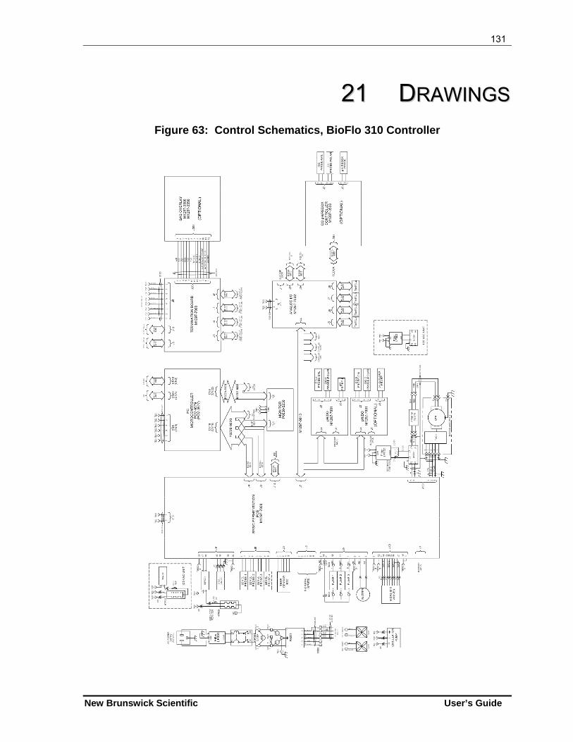
131
New Brunswick Scientific User’s Guide
2211 DDRRAAWWIINNGGSS Figure 63: Control Schematics, BioFlo 310 Controller
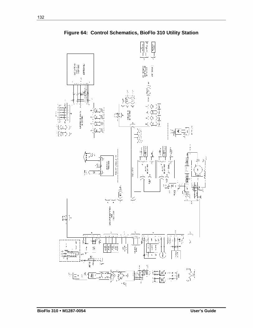
132
BioFlo 310 M1287-0054 User’s Guide
Figure 64: Control Schematics, BioFlo 310 Utility Station
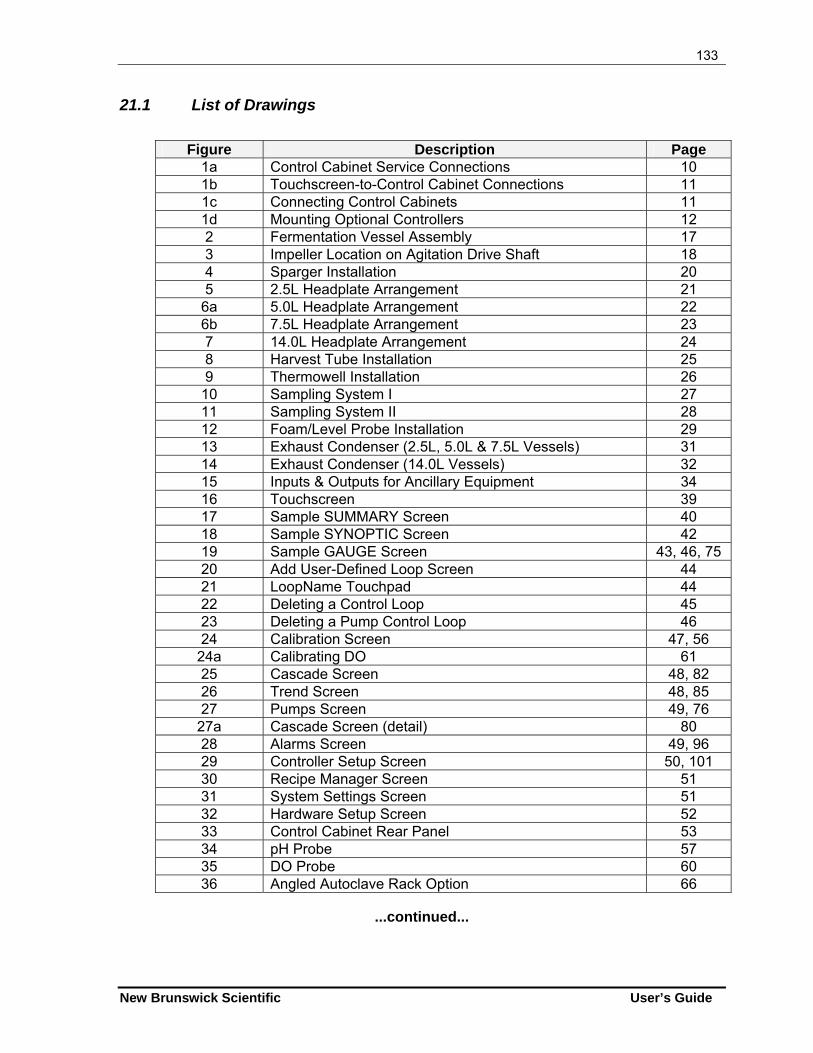
133
New Brunswick Scientific User’s Guide
21.1 List of Drawings
Figure Description Page
1a Control Cabinet Service Connections 10 1b Touchscreen-to-Control Cabinet Connections 11 1c Connecting Control Cabinets 11 1d Mounting Optional Controllers 12 2 Fermentation Vessel Assembly 17 3 Impeller Location on Agitation Drive Shaft 18 4 Sparger Installation 20 5 2.5L Headplate Arrangement 21
6a 5.0L Headplate Arrangement 22 6b 7.5L Headplate Arrangement 23 7 14.0L Headplate Arrangement 24 8 Harvest Tube Installation 25 9 Thermowell Installation 26
10 Sampling System I 27 11 Sampling System II 28 12 Foam/Level Probe Installation 29 13 Exhaust Condenser (2.5L, 5.0L & 7.5L Vessels) 31 14 Exhaust Condenser (14.0L Vessels) 32 15 Inputs & Outputs for Ancillary Equipment 34 16 Touchscreen 39 17 Sample SUMMARY Screen 40 18 Sample SYNOPTIC Screen 42 19 Sample GAUGE Screen 43, 46, 75 20 Add User-Defined Loop Screen 44 21 LoopName Touchpad 44 22 Deleting a Control Loop 45 23 Deleting a Pump Control Loop 46 24 Calibration Screen 47, 56
24a Calibrating DO 61 25 Cascade Screen 48, 82 26 Trend Screen 48, 85 27 Pumps Screen 49, 76
27a Cascade Screen (detail) 80 28 Alarms Screen 49, 96 29 Controller Setup Screen 50, 101 30 Recipe Manager Screen 51 31 System Settings Screen 51 32 Hardware Setup Screen 52 33 Control Cabinet Rear Panel 53 34 pH Probe 57 35 DO Probe 60 36 Angled Autoclave Rack Option 66
...continued...
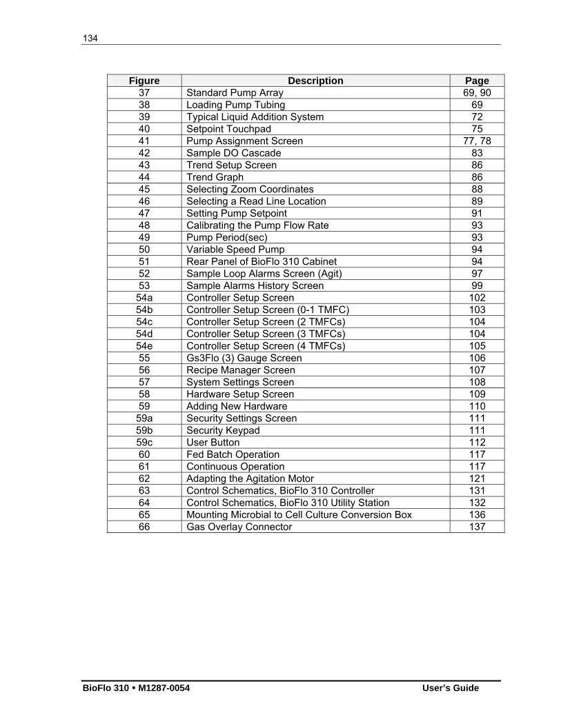
134
BioFlo 310 M1287-0054 User’s Guide
Figure Description Page 37 Standard Pump Array 69, 90 38 Loading Pump Tubing 69 39 Typical Liquid Addition System 72 40 Setpoint Touchpad 75 41 Pump Assignment Screen 77, 78 42 Sample DO Cascade 83 43 Trend Setup Screen 86 44 Trend Graph 86 45 Selecting Zoom Coordinates 88 46 Selecting a Read Line Location 89 47 Setting Pump Setpoint 91 48 Calibrating the Pump Flow Rate 93 49 Pump Period(sec) 93 50 Variable Speed Pump 94 51 Rear Panel of BioFlo 310 Cabinet 94 52 Sample Loop Alarms Screen (Agit) 97 53 Sample Alarms History Screen 99
54a Controller Setup Screen 102 54b Controller Setup Screen (0-1 TMFC) 103 54c Controller Setup Screen (2 TMFCs) 104 54d Controller Setup Screen (3 TMFCs) 104 54e Controller Setup Screen (4 TMFCs) 105 55 Gs3Flo (3) Gauge Screen 106 56 Recipe Manager Screen 107 57 System Settings Screen 108 58 Hardware Setup Screen 109 59 Adding New Hardware 110
59a Security Settings Screen 111 59b Security Keypad 111 59c User Button 112 60 Fed Batch Operation 117 61 Continuous Operation 117 62 Adapting the Agitation Motor 121 63 Control Schematics, BioFlo 310 Controller 131 64 Control Schematics, BioFlo 310 Utility Station 132 65 Mounting Microbial to Cell Culture Conversion Box 136 66 Gas Overlay Connector 137
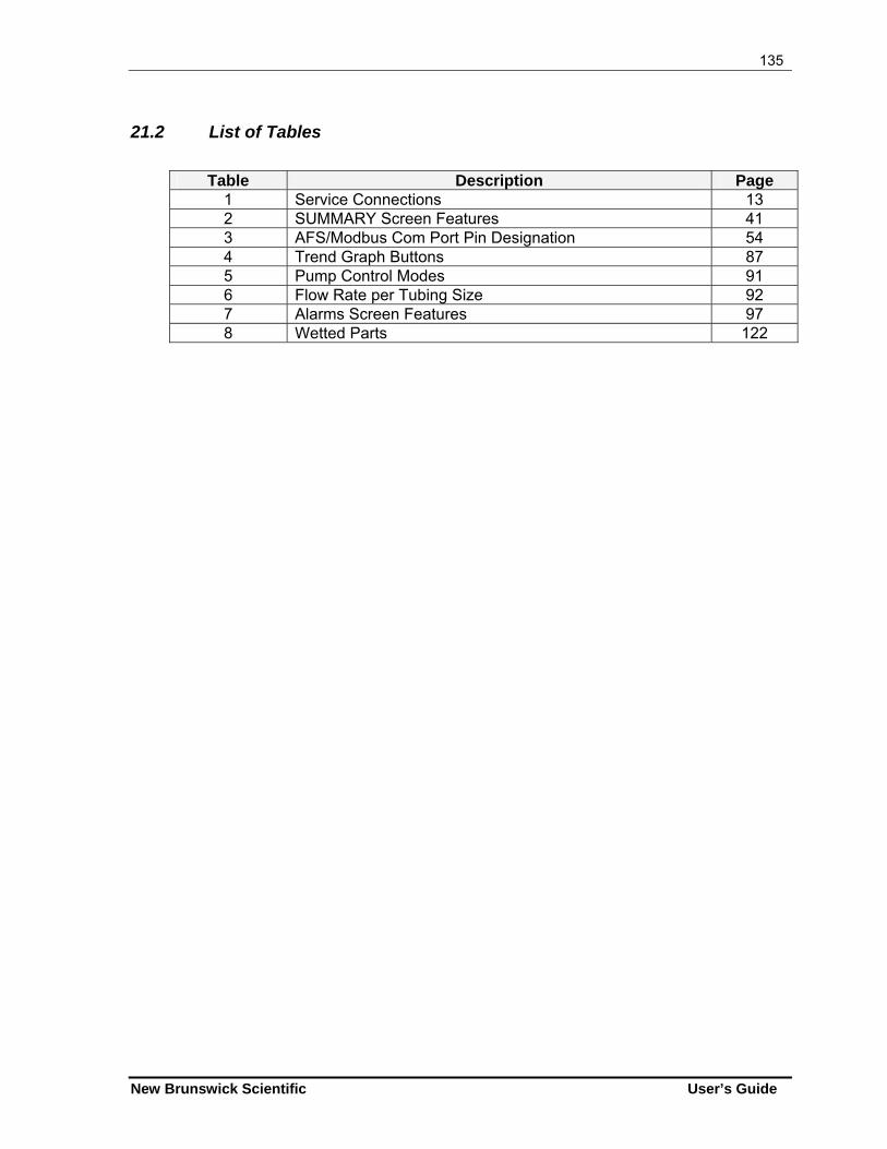
135
New Brunswick Scientific User’s Guide
21.2 List of Tables
Table Description Page
1 Service Connections 13 2 SUMMARY Screen Features 41 3 AFS/Modbus Com Port Pin Designation 54 4 Trend Graph Buttons 87 5 Pump Control Modes 91 6 Flow Rate per Tubing Size 92 7 Alarms Screen Features 97 8 Wetted Parts 122
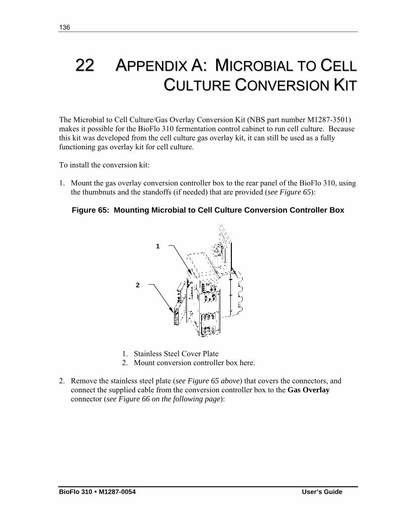
136
BioFlo 310 M1287-0054 User’s Guide
2222 AAPPPPEENNDDIIXX AA:: MMIICCRROOBBIIAALL TTOO CCEELLLL
CCUULLTTUURREE CCOONNVVEERRSSIIOONN KKIITT The Microbial to Cell Culture/Gas Overlay Conversion Kit (NBS part number M1287-3501) makes it possible for the BioFlo 310 fermentation control cabinet to run cell culture. Because this kit was developed from the cell culture gas overlay kit, it can still be used as a fully functioning gas overlay kit for cell culture. To install the conversion kit: 1. Mount the gas overlay conversion controller box to the rear panel of the BioFlo 310, using
the thumbnuts and the standoffs (if needed) that are provided (see Figure 65):
Figure 65: Mounting Microbial to Cell Culture Conversion Controller Box
1. Stainless Steel Cover Plate 2. Mount conversion controller box here.
2. Remove the stainless steel plate (see Figure 65 above) that covers the connectors, and connect the supplied cable from the conversion controller box to the Gas Overlay connector (see Figure 66 on the following page):
2
1
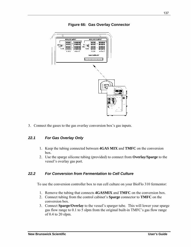
137
New Brunswick Scientific User’s Guide
Figure 66: Gas Overlay Connector
3. Connect the gases to the gas overlay conversion box’s gas inputs.
22.1 For Gas Overlay Only
1. Keep the tubing connected between 4GAS MIX and TMFC on the conversion
box. 2. Use the sparge silicone tubing (provided) to connect from Overlay/Sparge to the
vessel’s overlay gas port.
22.2 For Conversion from Fermentation to Cell Culture
To use the conversion controller box to run cell culture on your BioFlo 310 fermentor:
1. Remove the tubing that connects 4GASMIX and TMFC on the conversion box. 2. Connect tubing from the control cabinet’s Sparge connector to TMFC on the
conversion box. 3. Connect Sparge/Overlay to the vessel’s sparger tube. This will lower your sparge
gas flow range to 0.1 to 5 slpm from the original built-in TMFC’s gas flow range of 0.4 to 20 slpm.
138
BioFlo 310 M1287-0054 User’s Guide
4. Using the ¼-inch tubing adaptor provided, connect 4GASMIX to the bottom of your external rotameter. Connect the top of the rotameter to the vessel for overlay gas. The gas overlay is now manually controlled via the rotameter and the conversion box’s 4-gas manifold.
5. On the touchscreen display, choose the Setup Screen; make sure the control mode is set to Cell Culture and make sure the gas overlay is selected with the automatic gas flow control. In the Setup Screen, press the Save Changes button to generate the OvlFlo and OvlMix loops.
6. From the Gauge Screen, set the GasFlo loop setpoint to 20 slpm and set the control mode to AUTO.
7. From the Gauge Screen, set the OvlFlo loop setpoint to your preferred sparger gas flow rate, as it is now the sparger flow rate controller.
8. OvlMix still controls the mixing of the overlay gas. The overlay gas flow rate is manually controlled via the rotameter; adjust the rotameter to get the preferred overlay gas flow rate.
139
New Brunswick Scientific User’s Guide
2233 AAPPPPEENNDDIIXX BB:: SSOOMMEE GGEENNEERRAALL
CCOONNCCEEPPTTSS
NOTE: In this section, all discussions of P-I-D control are to explain the theory on which it is based. This product uses only P (proportional) & I (integral) control, not D (derivative).
23.1 What is a Controller?
The local process controller is a multi-loop controller, which means it can control several process parameters simultaneously. It compares current values with setpoints and creates independent control signals for each controlled parameter. The control signals are used to drive appropriate actuators that maintain the various parameters at their setpoints. Using temperature as an example, the controller compares the output of a temperature sensor to the user-entered temperature setpoint, and generates a signal to activate either a heater or a cooler to maintain vessel temperature at the temperature setpoint. The controller provides the logic that generates appropriate drive signals to various actuators so that process parameters remain at their setpoints.
23.2 What is a Control Loop?
A control loop is the basic element of automatic process control. Three components comprise one control loop: a sensor, a controller, and an actuator. Based on information from a sensor, the controller generates an actuator control signal that maintains a parameter at its setpoint. Control will fail if any element in the control loop fails.
140
BioFlo 310 M1287-0054 User’s Guide
23.3 What is Probe Calibration?
In bioprocess control, calibration generally refers to establishing a correspondence between a probe’s output and the actual value of whatever that probe senses. For example, pH probes are often calibrated with pH 7.0 and pH 4.0 buffers to establish a “zero” (pH 7.0) and a “span” (pH 4.0). Other buffers can be used, but the principle is always the same. For any probe calibration, two values—a zero and a span—are required for the controller to correctly translate inputs from that probe. DO and pH probes are routinely calibrated before each use. Most other probes need be calibrated only infrequently.
23.4 What are P-I-D Constants?
The mathematics of P-I-D control is familiar to most control and process engineers.
In P-I-D mode, the controller creates a control signal that is based upon the deviation between the setpoint and input from a sensor. The magnitude of the control signal is determined by a mathematical formula that can include proportional (“P”), integral (“I”) and derivative (“D”) terms. The P, I and D constants are three numbers that determine the relative sizes of the proportional, integral and derivative terms, respectively. To use a temporal analogy, the P or proportional part of the control signal reflects present deviations between setpoint and current value. The I or integral component reflects past deviations, and the D or derivative term anticipates future values of the error.
Generally, with noisy or slow-responding sensors, such as dissolved oxygen and pH probes, the D constant should be set to zero. If the constants for a loop are too large, that loop will oscillate, displaying extreme swings in actuator output. If, for example, agitation changes suddenly and frequently between minimum and maximum RPM, one should suspect incorrect P, I and D values for the agitation control loop. This condition can easily be mistaken for a defective component when it actually results from incorrect settings.
If the constants are too small, control response will be slow, and setpoints may never be reached. Again, this can be mistaken for defective components. P-I-D constants are usually established by methodical trial and error.
141
New Brunswick Scientific User’s Guide
23.5 What is P-I-D Tuning?
Tuning consists of establishing controller settings (the proportional, integral, and derivative constants) such that the controller provides proper control. If the P-I-D constants are incorrect, the control signal may be too weak for the parameter to ever reach setpoint or, at the other extreme, the controller may respond excessively to small errors, causing the actuator to oscillate between high and low values. Usable P-I-D constants must be determined for each P-I-D loop. The process is largely one of calculated trial and error. All loops that are configured with the P-I-D control mode must be tuned. When delivered as part of an NBS system, P-I-D loops will have been tuned at the factory to work correctly with the NBS-controlled instruments. For other applications, the user is responsible for P-I-D tuning. Tuning can be a complex task for those unfamiliar with the process, which is why a trained engineer or technician normally performs this task. A number of textbooks1 that explain the theory and describe the process could be useful for the mathematically-inclined novice. The Ziegler-Nichols method, described in the footnoted reference, is used at our production facilities. The following suggestions are intended for novices. Be sure to refer to a textbook, and consider utilizing the services of a technician. Allow sufficient time for the task. Tuning is an iterative process. It consists of
configuring a loop with trial P, I and D values, evaluating loop response, then readjusting the constants. The process is repeated until the loop responds fully and without oscillation.
One usually begins with a trial P, setting I and D to zero. After P is established, a
similar iterative process establishes I. Most fermentor probes respond too slowly or are too noisy to utilize the D term to
advantage. In most cases, D should remain at zero. Agitation is sometimes an exception.
The magnitude of the control signal depends on the P, I and D constants. It also
depends inversely on a Normalizing Constant.
1 For example, Chinks, F.G., Process Control Systems: Application, Design, and Tuning, McGraw-Hill (1988), New York, Auckland, Bogota, London, Toronto, Sydney, Tokyo, Montreal.
142
BioFlo 310 M1287-0054 User’s Guide
23.6 What Do the Constants Mean?
The control signal, SN, for a loop that is N seconds into a run is expressed mathematically as:
SN = P(eN/k) + (I/60)(en/k) + D[(eN-eN-1)/k]
Where:
P, I, and D are, respectively, the proportional, integral and derivative constants
e is the loop setpoint minus the current value, or error
k is a normalizing constant for the loop
The controller reevaluates SN every second. I is divided by 60, so any value entered by the user should be in reciprocal minutes.
The normalizing constant k can be set to any non-zero value, but is usually set to the full-scale reading of the loop. For example, if the range of expected temperatures is 0 to 125, setting k to 125 results in a P term value of P when the error is at a maximum, i.e.:
P(eN/k) = P(125/125) = P
Similarly, with a full-scale error, the I term (after 1 minute) and the D term will be I and D respectively.
143
New Brunswick Scientific User’s Guide
2244 AAPPPPEENNDDIIXX CC:: OOTTRR
24.1 Determining an Oxygen Transfer Rate
The oxygen transfer rate (OTR) of all NBS fermentors is determined by a standard sulfite oxidation test. The standard operating conditions for determining OTR are:
Temperature: 30C Agitation: 1000 RPM Aeration: 1 VVM
24.1.1 OTR Calculations
OTR can be estimated by titrating a fixed amount of sodium sulfite, Na2SO3, with air, CU+2: 2SO3 + 02 2SO4
The Procedure
Calibrate the DO electrode: Set zero on DO. Fully oxygenate the fermentor with agitation and airflow. Set span to 100%. Introduce a known amount of Na2SO3 into the fermentor when fully oxygenated. OTR = 30,000 n mM O2/L/hr
V T
n = number of moles of sodium sulfite
V = vessel volume in liters T = time taken from DO curve at two points of 50% DO min.
144
BioFlo 310 M1287-0054 User’s Guide
24.2 Some Factors that Affect OTR And Horsepower
Many factors influence OTR, not the least of which are type, size and placement of impellers in the reactor. (Factors which effect OTR are vessel dimensions, impeller diameter, type of impeller, i.e. turbine, marine, pitched blade, etc.). New Brunswick Scientific selects and recommends the placement of impellers in the vessel to attain a minimum of 350 mM O2/L/hr of OTR. The BioFlo 310 fermentor is supplied with two properly sized Rushton Impellers. Placement of the impellers should be as indicated in Figure 3.
In some processes, users may wish to use a third impeller. Should this be the case, however, a smaller impeller diameter is required, since the systems are specifically designed such that the vessel diameter, motor, impellers, to produce a specific OTR. When any of the factors is changed, other features may also change. For example, the standard impeller used on the 10-liter BioFlo 310 has a 3.24-inch (± 0.015) diameter. If three impellers are to be used, 3.06” diameter impellers are required. This size impeller is normally used in a 7.5L BioFlo 310 vessel. These impellers should be placed such that the bottom impeller is placed one impeller diameter from the bottom of the vessel. The second impeller should be placed one impeller diameter above the bottom impeller, and the third impeller should be placed one impeller diameter above the second. To determine the horsepower utilized by a given number of impellers, the following formula can be used. The impeller diameter varies to the 5th power with respect to horsepower. A very slight change in the diameter of an impeller can make a great deal of difference in the HP required to drive that impeller.
The approximate horsepower utilized to drive a given set of impellers is determined as follows:
HP = D5 x RPM3 x (4.5 x 10-13) x I
Where:
HP = Horsepower D = Impeller diameter in inches RPM = Agitator speed in RPM 4.5 x 10-13 = Constant (factor based on unaerated water at 20C
with a six-bladed Rushton impeller) I = factor based on the number of impellers used in the
vessel: Use 1 for one impeller Use 1.8 for two impellers Use 2.4 for three impellers

145
New Brunswick Scientific User’s Guide
NOTE: The HP requirements are substantially affected by aeration. An airflow rate of one vessel volume per minute (VVM) may produce as much as 40% reduction in the horsepower used. It is required that some air/gas flow be utilized when running at speeds above 750 RPM. The relationship in the reduction of horsepower when gas is added into the system is not linear. A small amount of air can produce a 20% reduction in horsepower.
146
BioFlo 310 M1287-0054 User’s Guide
2255 AAPPPPEENNDDIIXX DD:: FFEERRMMEENNTTAATTIIOONN
TTEECCHHNNIIQQUUEESS The following section outlines step-by-step procedures for carrying out a benchtop fermentation. Provided in a question and answer format, this discussion covers such topics as which media formulation, tubing size, and concentration of various additives should be used. It also addresses the preparation, autoclaving and clean-up procedures for the vessel and accessories. While this example refers specifically to an E. coli fermentation in a BioFlo 310, the information is generally applicable for any fermentation.
25.1 Media Formulation
Question: What kind of media should be used, and does it differ from media used in shake flasks? Answer: The media used in shake flasks does differ from the standard media used in a fermentation vessel. Shake flask media is generally of a much simpler composition. LB Broth and Tryptic Soy Broth are standard shake flask media. Here is an example of a more complex media used in a recombinant E. coli fermentation:
Chemical g/L KH2PO4 3.5 K2HPO4 5.0 (NH4)2HPO4 3.5 MgSO4
.7H2O 0.5 Glucose 5.0 (for fed batch) 30.0 (for batch) Yeast Extract 5.0 Trace Metals 1.0 ml/L Antifoam 0.5 ml/L
Trace metals formulation: FeCl3 1.6 CoCl2
.6H2O 0.2 CuCl2 0.1 ZnCl2
.4H2O 0.2 NaMoO4 0.2 H3BO4 0.05 Hcl 10 ml H2O to 1000 ml
147
New Brunswick Scientific User’s Guide
For fermentation, the glucose solution is usually sterilized in a separate flask. It is then added aseptically to the other (heat labile) components that cannot be subjected to autoclaving, such as Ampicillin and the trace metal solution. These are prepared in advance by sterile filtration so that they are available as stock solutions. The magnesium sulfate is sometimes sterilized separately. Most materials are available from a variety of vendors. Note that Sigma and Difco are often the best sources for the more unusual biological and chemical materials. The exact formulations of the trace metals solution and the fermentation media for the fermentors will depend on the precise fermentation you wish to conduct. Various formulations can be found in the handbooks and literature.
25.2 Antifoam Formulation
Question: What kind of antifoam should be used, and in what concentration?
Answer: Please visit our website at www.nbsc.com (click on the FAQs tab, then click on Fermentation and Cell Culture) for recommendations on types of antifoam agents to use. The initial concentration of antifoam is usually 0.1-0.5 ml/L. When the foam probe is used, the pumping of antifoam is controlled by the unit. The pump should be set to add the minimum amount of antifoaming agent required to prevent foaming in your particular process. That amount varies depending on the amount of protein in the media, the amount of protein secreted by the microorganism, agitation speed, and other factors. Therefore, you will have to experiment to get the proper pump setting.
25.3 Tubing Size
Question: What is the correct tubing size for acid, base, antifoam and nutrient feed for a fed-batch run?
Answer: For vessels up to 5 liters, NBS part number TU202. This is Marprene tubing with an inside dimension (ID) of 1.6 mm. It has an OD of 4.8mm (3/16"NOM) and a wall thickness of 1.6mm. Larger tubing will be required for vessels over 5 liters. It may also be necessary to use a connecting fitting to allow two different tubing sizes to be used (in cases when the tubing size required for the pump and the size required for the direct connection to the vessel differ). NBS recommends silicon tubing for use with the pump heads provided as standard on BioFlo fermentors. However, Marprene tubing may be used as well, as long as the tubing size does not exceed 3/16” bore x 1/16” wall. Marprene tubing of this size or smaller can be used with Watson-Marlow 101 pump heads under low pressure and with clockwise rotation.
148
BioFlo 310 M1287-0054 User’s Guide
Take note that silicon tubing should not be used with hydrochloric acid (HCL), sulfuric acid (H2SO4)) or sodium hydroxide solutions since this material deteriorates rapidly when in contact with such solutions. Another reason for avoiding HCL is that HCL (and to a lesser extent H2SO4 ) causes corrosion of stainless steel. NaOH solutions equal to or less than 20% can be used in silicon tubing at temperatures less than 120 F without destroying the tubing. Solutions of sulfuric acid less than 10% can cause moderate damage to silicon tubing.
25.4 Acid & Base
Question: What concentration and type of acid and base should be used?
Answer: The acid solution is 2 - 3N H2SO4. The base solution is either 5N NaOH or NH4OH ~ 29% (which is the standard commercially available concentration.) Note that these are fairly concentrated. The acid can affect the stainless steel parts of the fermentor vessel. To avoid damage to the entry ports, it is a good idea to use a sterile, disposable needle at the end of the addition tubing and to add the acid (or base) through the disposable needle. The needle will corrode, but it saves the fermentor vessel. Insert the needle though a septum port so that the drip point is away from stainless steel components and fairly close to the liquid level. You may also use a more diluted solution of the acid or base. However, take note that this may cause the complication of adding a larger volume of liquid to the vessel. Also, it is not a good idea to add acid and base through a single double or triple port adapter. The combined effects of both causes rapid corrosion of the adapter.
The pump setting is usually 20.0 - 25.0 under acid or base mode. For these concentrations of acid and base, Marprene tubing should be used. To avoid damage to the stainless steel headplate, use a septum port for introduction of these strong solutions into the vessel. If you are using silicon tubing, reduce the concentration of H2SO4 to less than 8% (about 5%) and use a 20% solution of NaOH. When selecting an acid for use in fermentation, select the lowest possible concentration that allows for pH control.
25.5 Glucose Feed
Question: What is the proper concentration of glucose feed?
Answer: The glucose is 50% concentration. The feed rate is not usually a constant value as this will differ not only from run to run, but it will vary greatly over the course of a run, depending upon the organism's growth. This operation can be controlled automatically by BioCommand, NBS' proprietary Windows-based software.
149
New Brunswick Scientific User’s Guide
Glucose feeding can be set to respond to other sensor cues (such as DO level, the pH reading, the turbidity measurement, the glucose measurement, etc.). The pumping profile to be used must generally be determined through experimental experience.
25.6 Recommended Process Control Settings
Question: What are the recommended process control settings (i.e., temperature, pH, agitation speed, DO & gas sparge rate)? Answer: For E. coli, temperature is usually set to 32° - 35°C and pH is set at 7.0 - 7.2. For yeast the values are 30°C and a pH value of 5.0. Agitation speed is usually set to a minimum of 200 - 300 rpm with a maximum value of 1000 rpm. Dissolved oxygen (or DO) level is usually 30%. The gas sparge rate is generally 0.5 to 1.0 VVM.
25.7 Typical Fermentation Run
Question: Can you review the steps involved in set-up through shutdown of a fermentation run?
Answer: To answer properly, let's break the process down, as follows:
25.7.1 Vessel Preparation Before Autoclaving
It is advisable to rinse the previously cleaned vessel prior to use. When doing this, remember that all clamps must be open and the valve for the sampling tube must be in the open position. If the glass wool is going to be replaced for the run, then remove it (and the rubber sampler bulb) prior to rinsing. The protective bearing housing cap must also be in place. It will be necessary to hold the protective cap in place if you plan to invert the headplate while rinsing it. In this case it is usually advisable to also remove the clamps that hold the headplate onto the rest of the vessel, as failure to do so will result in their falling out during inversion. The pH and DO probes should not be in the headplate while you rinse it. All gas filters must be removed prior to rinsing. The sparger must, in particular, be checked to ensure that it isn't clogged. The headplate must be oriented in combination with the vessel and the internal baffle so as to allow for the exhaust condenser lines and the cooling jacket water lines to be connected. Also, the baffle must be positioned so that it does not interfere with the insertion of the pH and DO probes into their ports. Do not place the sample port to the rear of the vessel, and position it so that ample room is available to take a sample. It is advantageous to have the addition ports for acid, base, etc., on the same side as (or at least not opposite) the pumps. The old grease on the top of the glass cylinder should be wiped clean. Reapply grease (Dow Corning silicone grease) prior to installing the headplate:
150
BioFlo 310 M1287-0054 User’s Guide
smear a very thin layer around the top of the cylinder with your fingertip. (Take care to ensure that no residual grease remains on your hands when you touch other parts of the vessel.) When the headplate is in place, be sure to properly tighten the headplate clamps. All tubing connected to the headplate should be secured at the headplate connection point, as well as to any addition bottles or other connectors. A tie-gun is useful for this purpose. Note that both the air sparger and the exhaust line will have a terminal filter. (For the BioFlo 310 vessel, the NBS part numbers are P0200-0491 for the sparge line’s small filter, and P0200-0490 for the exhaust line’s large filter.) All tubing connected to ports that have their terminus within the vessel below the liquid level (i.e., the harvest and sparge ports) must be clamped prior to autoclaving. The sampler valve must be in the closed position. Other hoses, such as those attached to base or addition ports, should be clamped to facilitate sterile hook-ups. NBS primarily uses the following clamps: a Hosecock Clamp (Fisher catalog number 05-847) and a Hoffman Side Tubing Clamp (Fisher catalog number 05-875B).
Do not rely on polymer clamps to survive autoclaving; they often pop open in the autoclave. If you wish to use the newer polymer clamps during the running of your fermentation, then place them onto the tubing but leave them open. Use easily removable metal clamps to actually close the line during autoclaving. These may be removed after the vessel has been autoclaved. Be sure to use the polymer clamp to close off the tubing BEFORE you remove the metal clamp. Clamps can be placed at any point on tubing, but be sure they don't clamp down onto a port or connector, because that would interfere with proper sealing. The open end of the tubing should be covered with cotton, then with aluminum foil. The clamp on the tubing be below the foil & cotton. The sparger filter should also be covered, but not quite as tightly. The exhaust filter is usually not covered. All tubing should be inspected both prior to and after autoclaving to insure integrity. The above description also applies to any side harvest ports in use. Note that this type of port is often below the media fill line. It is also possible to use a hose that has been tied off and crimped at one end to provide a cap for the base port & addition port, as well as other ports. These caps must fit very securely over the port, in order to avoid loss of sterility due to displacement while autoclaving.
All O-rings should be checked for damage prior to autoclaving. All fittings must be checked for tightness. A loose fitting is often an indication that the small O-ring in the fitting assembly requires replacement.
151
New Brunswick Scientific User’s Guide
Verify that the bottom of the glass cylinder is properly secured to its base. The agitation shaft must have its protective cap on prior to autoclaving. It is advisable to check that the connectors from the unit to the vessel (cooling jacket water line and exhaust gas condenser) are compatible. This is a good time to check that the air and water lines to the unit are open and that (if required) an oxygen source is available and correctly connected.
The pH probe must be inspected prior to insertion: enough electrolyte must be present and in good condition, and the rubber stoppers must be securely in place. The pH probe must be properly calibrated prior to insertion in the headplate. (Be sure to carefully follow the manufacturer's instructions for probe calibration, or the instructions in this manual.) It is often necessary to coat the probe with a very thin layer of glycerin or deionized water in order to avoid jamming or breaking it during insertion. The pH probe must be inserted carefully, using two hands, with one hand holding the base of the probe near the port opening. Never force the probe, and never insert the pH or the DO probe until the headplate is properly secured. It is absolutely critical that both the pH and DO probes have their protective caps on prior to autoclaving; in fact, the caps should always be on except when the probe is being hooked up to the unit. NEVER autoclave a pH probe or a DO probe without its protective cap. Check the DO probe to be sure the required amount of electrolyte is present prior to insertion; NBS usually replaces electrolyte for each new run. The DO probe's membrane must also be inspected prior to use. The glass wool for the sampler is prepared by rolling a small quantity up and inserting it into the small tube that attaches to the bulb. It may be necessary to trim any glass wool fibers that stick out. Note that it is undesirable to pack glass wool too tightly; use the bulb and a sampling tube to see if a vacuum can be held and released properly, as when a sample is normally taken. Attach a sample tube prior to autoclaving. This tube should be ¼ to ½ turn loose to avoid explosion or implosion. The glass wool should be covered with a piece of foil.
25.7.2 Vessel Sterilization
When autoclaving, the unit exhausts through the exhaust filter, so it is essential that the line be prevented from crimping and that the filter be good (unplugged). To ensure that crimping does not occur, use a short piece of fairly rigid tubing. If rigid tubing is not available, use a small splint to support the tubing. The vessel is normally sterilized for 45 minutes. Note, however, that certain media formulations cannot be sterilized for this length of time, as degradation will occur (check the media manufacturer's instructions). The probes must never be autoclaved dry.
152
BioFlo 310 M1287-0054 User’s Guide
If it becomes necessary to sterilize the vessel without media, use a balanced salt (phosphate-buffered saline) solution to cover the ends of the probes. Aseptically remove the PBS prior to filling the vessel with the desired media. NEVER PLACE PROBES IN DISTILLED OR DEIONIZED WATER: THIS WILL CAUSE YOUR PROBE TO LOSE ELECTROLYTE. The maximum fill is ~70% of the vessel's maximum volume. Autoclaving should be done (when liquid is present in the vessel) on a slow exhaust setting (see autoclave manufacturer’s instructions for autoclaving liquids). Sterilization is at 121°C. When sterilization is complete, check the exhaust line to verify that it didn't crimp, and check the vessel's integrity.
25.7.3 Post-Sterilization Vessel Set-Up
The vessel must be handled gently when removed from the autoclave, to prevent the media from boiling up. Confirm that any unprotected vented lines are clamped off upon removing the vessel from the autoclave. Check the vessel's integrity again, then transport it to the bench unit.
Place the vessel next to the control cabinet. The orientation must allow for proper hook-up to the cooling jacket water lines and the exhaust gas condenser lines. Connect the water lines, connecting the outgoing (return) lines before the incoming (delivery) lines, and ensuring that the delivery and return lines are not inverted. Insert the temperature probe into the thermowell. Check that the water lines to the unit are open. Set the temperature value below ambient temperature and set the control to Auto. If using an external recirculating chiller, it also must be turned on at this time, and the water level in the chiller should also be checked prior to use; this will prime the jacket. After ~2-5 minutes, the unit can be switched to the desired temperature setting. This can be checked by making sure that water is truly leaving the unit: observe the water drained through the Drain or Water Out port. Remove the protective caps from the pH and DO probes and connect the probes to the unit. Be careful with the pH probe: do not twist the probe into its connection to the unit, as this can compromise sterility. The connection must be screwed onto the probe. The pH probe should also be checked to ensure that its rubber stoppers have not been displaced. Note the time that the DO probe is connected, since the probe requires a minimum of 6 hours for polarization.
Remove the bearing housing cap and attach the motor. Open the SUMMARY screen and set the air from OFF to O2 Enrichment. Return to the SUMMARY screen and make sure that GasFlow is in ON mode. Connect the air line from the unit to the sparger’s terminal filter as aseptically as possible (although the filter will prevent external contamination, good technique is always a good idea).
153
New Brunswick Scientific User’s Guide
Open the clamp on the sparger line and visually observe the vessel to ensure that air is flowing properly. Then set the agitation to the minimum desired value.
After set-up, the unit should be carefully observed to ensure that there are no problems, (especially no water line leaks).
25.7.4 Vessel Operation
The vessel must have any and all necessary addition bottles connected prior to use. If another bottle, such as the glucose feed, is not initially required, it can be hooked up later. The pH will probably need to be adjusted. This is done by setting the pH control to Auto. Note that due to the unit’s tendency to overshoot the target pH during this initial adjustment, it is desirable to set the initial pH setpoint a little conservatively. (For example: post-sterilization pH reading is 6.8, and desired setpoint is 7.2. Set the unit to setpoint 7.0 when conducting the initial adjustment.) Note that the pH reading must be taken from a vessel that has already cooled down. Additional media components that are not autoclaved can be added once the vessel has cooled sufficiently. The protocol for this is the same as for inoculation, as described below.
Inoculation can be performed by aseptically pouring liquids into the vessel through the inoculation port, although NBS normally uses the harvest port to inoculate. A peristaltic pump or gravity is used to introduce the inoculum. The shake flask is connected to the port terminus using aseptic techniques, and then the clamps are opened to allow for addition. Once the material is all in (except for any residual inoculum which must be retained for testing), secure the clamps and disconnect the shake flask. At this point, the harvest port terminus must be covered up again, using asceptic techniques, with sterile cotton and foil. To harvest from the vessel, attach a line to the harvest port and use a peristaltic pump to pump the culture broth out.
25.7.5 Vessel Shutdown & Cleaning
When the fermentation run is complete, it is necessary to carefully shut the process down. First, all operating parameters (agitation, temperature, DO level, pH, and gas feed) must be set from their current control modes (such as Auto, Manual, or ON) to the OFF mode.
154
BioFlo 310 M1287-0054 User’s Guide
Additionally, if a supplemental oxygen feed was used, it will be necessary to close the gas tank valve and its lines to the unit. If a recirculating chiller is in use, it should be shut off when the temperature control is shut off. Clamp off the feed lines (from any addition bottles used) prior to detaching them from the vessel.
The next step is to disconnect the vessel from the unit. Remove the temperature probe from the thermowell. Remove the motor and place the protective cap over the agitation shaft/bearing housing. When you disconnect the water lines, always disconnect the incoming lines prior to the outgoing lines. Disconnect the air line from the sparger. Disconnect the pH and DO probes from the unit, and put on their protective caps. The DO probe presents an easy removal as you simply unscrew the thread and gently pull it out. Immediately rinse it off, then gently wipe it dry, always remembering to never touch the membrane at the tip. Some runs will result in an accumulation of biomaterial on the probe, so and it may be necessary to wipe the probe down more vigorously; nevertheless, in no case should the tip be touched. After cleaning the DO probe, visually inspect the tip for damage. (If it is damaged, replace the probe.) Store the probe in a clean area in such a way as to protect the sensitive tip. Removing the pH probe is usually not so difficult inserting it because the shaft is wet and should be relatively easy to remove. The danger of probe breakage is still very real, however, so extreme care must be taken while removing it. Be sure to use two hands, with one hand at the top of the port acting as a guide to ensure proper removal. A gentle pace is required; if at any point in the process the probe should jam, absolutely avoid forcing. It may be necessary to reinsert the probe partway, and to apply a lubricant such as glycerin to the shaft and port in order to effect the removal. In extreme cases, it may be necessary to remove the headplate with the probe still inside so that you can approach the problem from both ends. In such a case, it is critical to remove the headplate very carefully. (We recommend that you have a spare probe available at all times, in case of breakage.) Once the pH probe has been removed, it should be immediately washed off with warm water. If biomaterial has accumulated on the probe, use a sponge (or an equivalent that will not scratch glass) with gentle pressure to clean the surface. The very tip of the probe should be handled with extreme care and a Kimwipe should be used to gently dry it off after washing. The probe should be stored with the tip immersed in either electrolyte or pH 7 buffer. This electrolyte/buffer can be reused, but it should always be inspected prior to each use for precipitation or contamination.
155
New Brunswick Scientific User’s Guide
Now that the vessel is detached from the unit, it can be cleaned. Remove any remaining cotton and foil covering the ports. The rubber sampler bulb should be removed and rinsed separately. The glass wool can be removed at this point, too. Detach the sampling tube and wash it separately. Open the valve on the sampling port and all clamps on all tubing connected to ports for proper washing (be sure to remove the media prior to unclamping any tubing below liquid level, such as a side harvest line). The headplate should be detached by loosening and then removing the clamps that hold it to the rest of the vessel. Those clamps may require rinsing. The remaining culture broth should be sterilized, or emptied into a bucket and disinfected by using bleach or other accepted disinfectant prior to disposal. Note that some media may be incompatible with this procedure, in which case the media can be placed into another container for sterilization prior to disposal. The headplate should be washed thoroughly with warm water and then with deionized (DI) water. It may be necessary to scrub off any accumulations of biomaterial. A pad that won't scratch the steel is required for this. The agitation shaft, thermowell, harvest and sparger tubes, and the short beveled tips of the interior portion of the base-type addition ports will often require special attention. All tubes and shafts must be cleaned. Note that there may be some residual base or acid left in those lines, so extreme caution and the use of chemically-resistant gloves is highly recommended for this procedure. It is often necessary to hand wipe surfaces with a paper towel in order to fully remove residual traces of small particulate debris.
The washing of the bottom portion of the vessel requires the same procedures as the headplate. Note that the sides of the vessel, particularly near the baffle, may require special attention.
The vessel can now be cleaned by washing with detergent, or by using a cleaning solution. If the vessel is to be sterilized, all standard precautions must be taken. Note that for this purpose, the vessel does not need to be sealed except for those previously cited valves and tubing which run under the liquid level. It will be necessary to use water in the vessel. We recommend the use of DI (deionized) water, and the fill should be at least as high as your standard level for a run. Unless you have already specifically wiped the residual grease off the top of the glass cylinder, there should be enough so that the headplate can be clamped to the glass vessel. DO NOT tighten the headplate clamps with the same force used to install the headplate prior to a run, as this could lead to vessel damage. Instead, the lightest possible pressure should be used.
156
BioFlo 310 M1287-0054 User’s Guide
The advantage to sterilization is that not only are residual viable organisms killed, but also residual debris will loosen and become removable by washing after the vessel has cooled. If a cleaning solution is required, we recommend a 10% dilution of Micro cleaning solution (International Products Corporation, catalog number 6732). Alternatively, if you are using the vessel for consecutive runs with the same media, rinsing it with warm tap water and with DI water may suffice. Note that if water will run over a vessel surface that is greased, the grease should be removed: wipe it off with a wet paper towel.
In cases where the vessel must be decontaminated prior to cleaning, add water so that the liquid level reaches the maximum working volume of the vessel. This will help prevent biological materials from adhering.

157
New Brunswick Scientific User’s Guide
2266 AAPPPPEENNDDIIXX EE:: CCOORRRROOSSIIOONN
RREESSIISSTTAANNCCEE Websites such as www.outokumpu.com provide up-to-date information about the 316 type stainless steel used in your BioFlo 310 vessels.
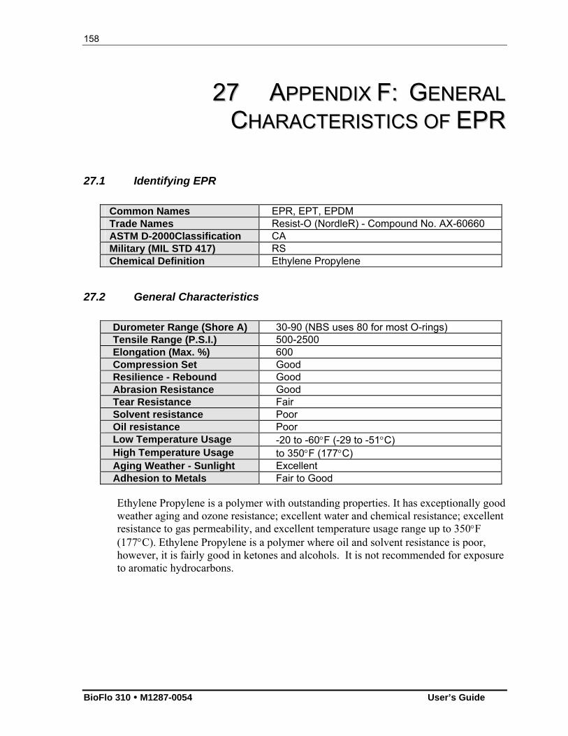
158
BioFlo 310 M1287-0054 User’s Guide
2277 AAPPPPEENNDDIIXX FF:: GGEENNEERRAALL
CCHHAARRAACCTTEERRIISSTTIICCSS OOFF EEPPRR
27.1 Identifying EPR
Common Names EPR, EPT, EPDM Trade Names Resist-O (NordleR) - Compound No. AX-60660 ASTM D-2000Classification CA Military (MIL STD 417) RS Chemical Definition Ethylene Propylene
27.2 General Characteristics
Durometer Range (Shore A) 30-90 (NBS uses 80 for most O-rings) Tensile Range (P.S.I.) 500-2500 Elongation (Max. %) 600 Compression Set Good Resilience - Rebound Good Abrasion Resistance Good Tear Resistance Fair Solvent resistance Poor Oil resistance Poor Low Temperature Usage -20 to -60F (-29 to -51C) High Temperature Usage to 350F (177C) Aging Weather - Sunlight Excellent Adhesion to Metals Fair to Good Ethylene Propylene is a polymer with outstanding properties. It has exceptionally good weather aging and ozone resistance; excellent water and chemical resistance; excellent resistance to gas permeability, and excellent temperature usage range up to 350F (177C). Ethylene Propylene is a polymer where oil and solvent resistance is poor, however, it is fairly good in ketones and alcohols. It is not recommended for exposure to aromatic hydrocarbons.
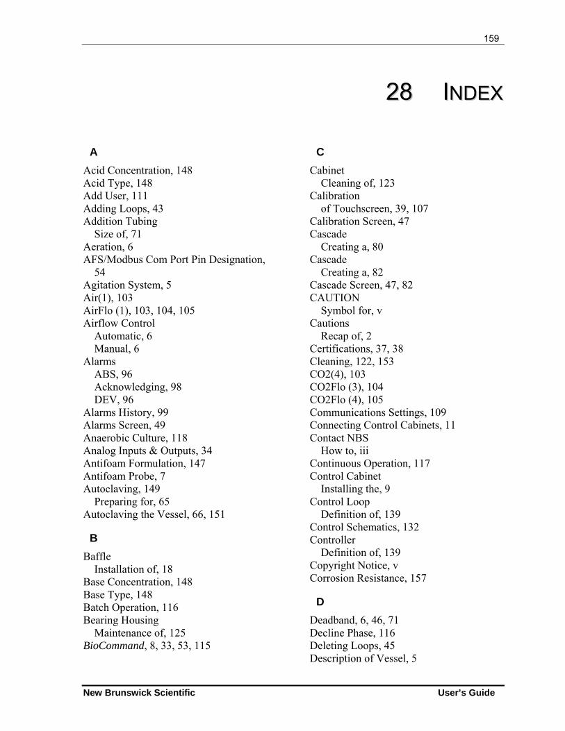
159
New Brunswick Scientific User’s Guide
2288 IINNDDEEXX
A
Acid Concentration, 148 Acid Type, 148 Add User, 111 Adding Loops, 43 Addition Tubing
Size of, 71 Aeration, 6 AFS/Modbus Com Port Pin Designation,
54 Agitation System, 5 Air(1), 103 AirFlo (1), 103, 104, 105 Airflow Control
Automatic, 6 Manual, 6
Alarms ABS, 96 Acknowledging, 98 DEV, 96
Alarms History, 99 Alarms Screen, 49 Anaerobic Culture, 118 Analog Inputs & Outputs, 34 Antifoam Formulation, 147 Antifoam Probe, 7 Autoclaving, 149
Preparing for, 65 Autoclaving the Vessel, 66, 151
B
Baffle Installation of, 18
Base Concentration, 148 Base Type, 148 Batch Operation, 116 Bearing Housing
Maintenance of, 125 BioCommand, 8, 33, 53, 115
C
Cabinet Cleaning of, 123
Calibration of Touchscreen, 39, 107
Calibration Screen, 47 Cascade
Creating a, 80 Cascade
Creating a, 82 Cascade Screen, 47, 82 CAUTION
Symbol for, v Cautions
Recap of, 2 Certifications, 37, 38 Cleaning, 122, 153 CO2(4), 103 CO2Flo (3), 104 CO2Flo (4), 105 Communications Settings, 109 Connecting Control Cabinets, 11 Contact NBS
How to, iii Continuous Operation, 117 Control Cabinet
Installing the, 9 Control Loop
Definition of, 139 Control Schematics, 132 Controller
Definition of, 139 Copyright Notice, v Corrosion Resistance, 157
D
Deadband, 6, 46, 71 Decline Phase, 116 Deleting Loops, 45 Description of Vessel, 5
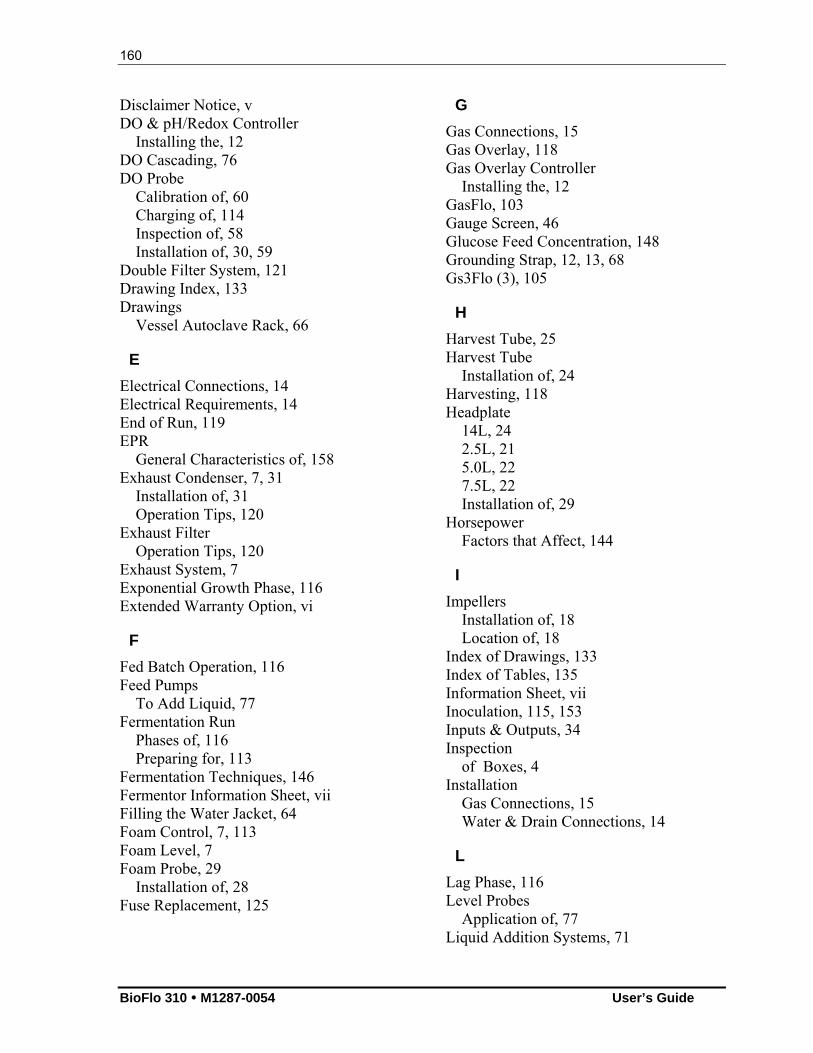
160
BioFlo 310 M1287-0054 User’s Guide
Disclaimer Notice, v DO & pH/Redox Controller
Installing the, 12 DO Cascading, 76 DO Probe
Calibration of, 60 Charging of, 114 Inspection of, 58 Installation of, 30, 59
Double Filter System, 121 Drawing Index, 133 Drawings
Vessel Autoclave Rack, 66
E
Electrical Connections, 14 Electrical Requirements, 14 End of Run, 119 EPR
General Characteristics of, 158 Exhaust Condenser, 7, 31
Installation of, 31 Operation Tips, 120
Exhaust Filter Operation Tips, 120
Exhaust System, 7 Exponential Growth Phase, 116 Extended Warranty Option, vi
F
Fed Batch Operation, 116 Feed Pumps
To Add Liquid, 77 Fermentation Run
Phases of, 116 Preparing for, 113
Fermentation Techniques, 146 Fermentor Information Sheet, vii Filling the Water Jacket, 64 Foam Control, 7, 113 Foam Level, 7 Foam Probe, 29
Installation of, 28 Fuse Replacement, 125
G
Gas Connections, 15 Gas Overlay, 118 Gas Overlay Controller
Installing the, 12 GasFlo, 103 Gauge Screen, 46 Glucose Feed Concentration, 148 Grounding Strap, 12, 13, 68 Gs3Flo (3), 105
H
Harvest Tube, 25 Harvest Tube
Installation of, 24 Harvesting, 118 Headplate
14L, 24 2.5L, 21 5.0L, 22 7.5L, 22 Installation of, 29
Horsepower Factors that Affect, 144
I
Impellers Installation of, 18 Location of, 18
Index of Drawings, 133 Index of Tables, 135 Information Sheet, vii Inoculation, 115, 153 Inputs & Outputs, 34 Inspection
of Boxes, 4 Installation
Gas Connections, 15 Water & Drain Connections, 14
L
Lag Phase, 116 Level Probes
Application of, 77 Liquid Addition Systems, 71
161
New Brunswick Scientific User’s Guide
Loading Pump Tubing, 69 Location
Environment, 9 Physical, 9
Loop Setpoints Entering the, 74 Modifying the, 75
M
Main Power Switch, 33 Maintenance, 124 Maintenance Inspections, 125 Manual Conventions, v Mass Flow Controller, 6 Media Formulation, 146 Microaerophilic Culture, 118 Motor Assembly
Installation of, 30 Motor Replacement, 125
N
NBS Offices, iii NOTE
Symbol for, v
O
O2(2), 103 O2Flo (2), 103, 104, 105 Operating Controls, 39 Operating Tips, 120 OTR
Calculating an, 143 Determining an, 143 Factors that Affect, 144
P
P&I Gains, 59 P&I Values
Factory Settings, 74 Setting, 74
Parts Lists, 126 pH
Control of, 6 pH Probe, 6
Calibration of, 55
Inspection of, 55 Installation of, 30, 57 Maintenance of, 58 Storage of, 58
PID Explanation of Constants, 140 Explanation of Tuning, 141
Plotting Trends, 85 Preparing for a Fermentation Run, 113 Preparing Vessel for Autoclaving, 149 Probe Calibration
Definition of, 140 Probe Cleaning, 154 Probe Removal, 154 Probe Storage, 124, 154 Process Control Settings
Recommendations for, 149 Pump Array
Standard, 90 Pump Assignment, 76 Pump Assignment Screen, 77 Pump Calibration, 79, 92 Pump Control Modes, 91 Pump Flow Rate, 92 Pump Period (sec), 93 Pump Setpoints, 91 Pumps Screen, 49
R
Read Line, 88 Regulatory Compliance, 37 Remove User, 111 Renaming Control Loops, 43 Replacement Parts, 126 Rotameter, 6 RS232/422 Computer Interface, 52 RTD Probe
Installation of, 73
S
Sampler, 27, 28 Sampler Assembly
Installation of, 26 Sampling, 115
System I, 7 System II, 8
162
BioFlo 310 M1287-0054 User’s Guide
Saving a Process Configuration, 140, 141 Security Keypad, 111 Serial Inputs & Outputs, 34 Service, 129 Service Connections, 13 Service/Utility
Electrical, 14 Setting Alarms, 96 Setting Up the Vessel, 152 Setup Screen, 50, 101 Shutdown, 119, 153 Siliconizing the Vessel, 16 Sparger
Installation of, 20 Specifications, 35 Start-Up Screen, 40 Steady State Phase, 116 Sterilization
Preparing for, 65 Sterilization Temperature, 67 Sterilization Time, 67 Sterilizing the Vessel, 151 Summary Screen, 40 Summary Screen Features, 40 Supervisory Software, 8 Synoptic Screen, 42
T
Table Index, 135 Table of Contents, xiii Temperature
Control, 6 RTD, 6 Setpoint, 6
Temperature Probe Installation of, 73
Thermowell, 26 Installation of, 25
Touchscreen Calibrating the, 39, 107 Installing the, 9
Trend Graph, 86 Creating a, 85
Trend Graph Buttons, 87 Trend Screen, 48 Trend Setup Screen, 86 Troubleshooting, 129 Tubing Recommendations, 147 Tubing Size, 147
U
User Button, 111, 112 Utilities, 13
V
Vessel Description of, 5 Installation of, 30
Vessel Assembly Precautions, 120 Vessel Cleaning, 122, 153 Vessel Operation, 153 Vessel Preparation for Autoclaving, 149 Vessel Pressurization, 15 Vessel Set-Up, 152 Vessel Shutdown, 153 Vessel Sterilization, 151 Vessels
Siliconizing the, 16
W
WARNING Symbol for, v
Warnings Recap of, 1
Warranty, vi Option for Extended, vi
Warranty Registration, vi Water & Drain Connections, 14 Water Jacket
Filling the, 64 Wetted Parts, 122
Z
Zoom Coordinates, 88