Embed Size (px)
Citation preview
Automatic Transfer Switch
Operation and
Installation
Model:
RDT
100--400 Amp Automatic Transfer Switches
100 and 200 Amp Automatic Transfer Switches with Load Centers
200 and 400 Amp Service Entrance Rated Transfer Switches
Electrical Controls:
MPAC 500
TP-6345 9/13j
TP-6345 9/132
Product Identification Information
Product identification numbers determine service parts.
Record the product identification numbers in the spaces
below immediately after unpacking the products so that
the numbers are readily available for future reference.
Record field-installed kit numbers after installing the
kits.
Transfer Switch Identification Numbers
Record the product identification numbers from the
transfer switch nameplate.
Model Designation
Serial Number
Accessory Number Accessory Description
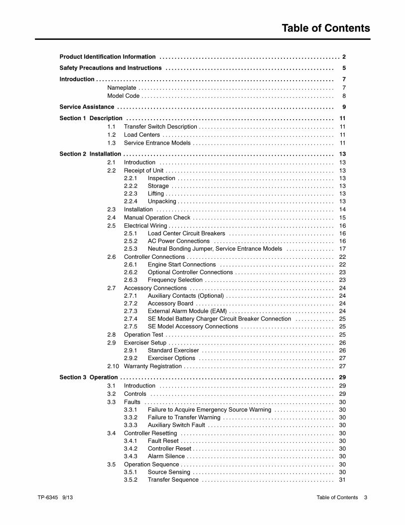
Table of Contents
TP-6345 9/13 Table of Contents 3
Product Identification Information 2. . . . . . . . . . . . . . . . . . . . . . . . . . . . . . . . . . . . . . . . . . . . . . . . . . . . . . . . . . . .
Safety Precautions and Instructions 5. . . . . . . . . . . . . . . . . . . . . . . . . . . . . . . . . . . . . . . . . . . . . . . . . . . . . . . .
Introduction 7. . . . . . . . . . . . . . . . . . . . . . . . . . . . . . . . . . . . . . . . . . . . . . . . . . . . . . . . . . . . . . . . . . . . . . . . . . . . . . .
Nameplate 7. . . . . . . . . . . . . . . . . . . . . . . . . . . . . . . . . . . . . . . . . . . . . . . . . . . . . . . . . . . . . . . . .
Model Code 8. . . . . . . . . . . . . . . . . . . . . . . . . . . . . . . . . . . . . . . . . . . . . . . . . . . . . . . . . . . . . . . .
Service Assistance 9. . . . . . . . . . . . . . . . . . . . . . . . . . . . . . . . . . . . . . . . . . . . . . . . . . . . . . . . . . . . . . . . . . . . . . . .
Section 1 Description 11. . . . . . . . . . . . . . . . . . . . . . . . . . . . . . . . . . . . . . . . . . . . . . . . . . . . . . . . . . . . . . . . . . . . .
1.1 Transfer Switch Description 11. . . . . . . . . . . . . . . . . . . . . . . . . . . . . . . . . . . . . . . . . . . . .
1.2 Load Centers 11. . . . . . . . . . . . . . . . . . . . . . . . . . . . . . . . . . . . . . . . . . . . . . . . . . . . . . . . .
1.3 Service Entrance Models 11. . . . . . . . . . . . . . . . . . . . . . . . . . . . . . . . . . . . . . . . . . . . . . .
Section 2 Installation 13. . . . . . . . . . . . . . . . . . . . . . . . . . . . . . . . . . . . . . . . . . . . . . . . . . . . . . . . . . . . . . . . . . . . . .
2.1 Introduction 13. . . . . . . . . . . . . . . . . . . . . . . . . . . . . . . . . . . . . . . . . . . . . . . . . . . . . . . . . .
2.2 Receipt of Unit 13. . . . . . . . . . . . . . . . . . . . . . . . . . . . . . . . . . . . . . . . . . . . . . . . . . . . . . . .
2.2.1 Inspection 13. . . . . . . . . . . . . . . . . . . . . . . . . . . . . . . . . . . . . . . . . . . . . . . . . . . .
2.2.2 Storage 13. . . . . . . . . . . . . . . . . . . . . . . . . . . . . . . . . . . . . . . . . . . . . . . . . . . . . .
2.2.3 Lifting 13. . . . . . . . . . . . . . . . . . . . . . . . . . . . . . . . . . . . . . . . . . . . . . . . . . . . . . . .
2.2.4 Unpacking 13. . . . . . . . . . . . . . . . . . . . . . . . . . . . . . . . . . . . . . . . . . . . . . . . . . . .
2.3 Installation 14. . . . . . . . . . . . . . . . . . . . . . . . . . . . . . . . . . . . . . . . . . . . . . . . . . . . . . . . . . .
2.4 Manual Operation Check 15. . . . . . . . . . . . . . . . . . . . . . . . . . . . . . . . . . . . . . . . . . . . . . .
2.5 Electrical Wiring 16. . . . . . . . . . . . . . . . . . . . . . . . . . . . . . . . . . . . . . . . . . . . . . . . . . . . . . .
2.5.1 Load Center Circuit Breakers 16. . . . . . . . . . . . . . . . . . . . . . . . . . . . . . . . . . .
2.5.2 AC Power Connections 16. . . . . . . . . . . . . . . . . . . . . . . . . . . . . . . . . . . . . . . .
2.5.3 Neutral Bonding Jumper, Service Entrance Models 17. . . . . . . . . . . . . . . .
2.6 Controller Connections 22. . . . . . . . . . . . . . . . . . . . . . . . . . . . . . . . . . . . . . . . . . . . . . . . .
2.6.1 Engine Start Connections 22. . . . . . . . . . . . . . . . . . . . . . . . . . . . . . . . . . . . . .
2.6.2 Optional Controller Connections 23. . . . . . . . . . . . . . . . . . . . . . . . . . . . . . . . .
2.6.3 Frequency Selection 23. . . . . . . . . . . . . . . . . . . . . . . . . . . . . . . . . . . . . . . . . . .
2.7 Accessory Connections 24. . . . . . . . . . . . . . . . . . . . . . . . . . . . . . . . . . . . . . . . . . . . . . . .
2.7.1 Auxiliary Contacts (Optional) 24. . . . . . . . . . . . . . . . . . . . . . . . . . . . . . . . . . . .
2.7.2 Accessory Board 24. . . . . . . . . . . . . . . . . . . . . . . . . . . . . . . . . . . . . . . . . . . . . .
2.7.3 External Alarm Module (EAM) 24. . . . . . . . . . . . . . . . . . . . . . . . . . . . . . . . . . .
2.7.4 SE Model Battery Charger Circuit Breaker Connection 25. . . . . . . . . . . . .
2.7.5 SE Model Accessory Connections 25. . . . . . . . . . . . . . . . . . . . . . . . . . . . . . .
2.8 Operation Test 25. . . . . . . . . . . . . . . . . . . . . . . . . . . . . . . . . . . . . . . . . . . . . . . . . . . . . . . .
2.9 Exerciser Setup 26. . . . . . . . . . . . . . . . . . . . . . . . . . . . . . . . . . . . . . . . . . . . . . . . . . . . . . .
2.9.1 Standard Exerciser 26. . . . . . . . . . . . . . . . . . . . . . . . . . . . . . . . . . . . . . . . . . . .
2.9.2 Exerciser Options 27. . . . . . . . . . . . . . . . . . . . . . . . . . . . . . . . . . . . . . . . . . . . .
2.10 Warranty Registration 27. . . . . . . . . . . . . . . . . . . . . . . . . . . . . . . . . . . . . . . . . . . . . . . . . .
Section 3 Operation 29. . . . . . . . . . . . . . . . . . . . . . . . . . . . . . . . . . . . . . . . . . . . . . . . . . . . . . . . . . . . . . . . . . . . . . .
3.1 Introduction 29. . . . . . . . . . . . . . . . . . . . . . . . . . . . . . . . . . . . . . . . . . . . . . . . . . . . . . . . . .
3.2 Controls 29. . . . . . . . . . . . . . . . . . . . . . . . . . . . . . . . . . . . . . . . . . . . . . . . . . . . . . . . . . . . .
3.3 Faults 30. . . . . . . . . . . . . . . . . . . . . . . . . . . . . . . . . . . . . . . . . . . . . . . . . . . . . . . . . . . . . . .
3.3.1 Failure to Acquire Emergency Source Warning 30. . . . . . . . . . . . . . . . . . . .
3.3.2 Failure to Transfer Warning 30. . . . . . . . . . . . . . . . . . . . . . . . . . . . . . . . . . . . .
3.3.3 Auxiliary Switch Fault 30. . . . . . . . . . . . . . . . . . . . . . . . . . . . . . . . . . . . . . . . . .
3.4 Controller Resetting 30. . . . . . . . . . . . . . . . . . . . . . . . . . . . . . . . . . . . . . . . . . . . . . . . . . .
3.4.1 Fault Reset 30. . . . . . . . . . . . . . . . . . . . . . . . . . . . . . . . . . . . . . . . . . . . . . . . . . .
3.4.2 Controller Reset 30. . . . . . . . . . . . . . . . . . . . . . . . . . . . . . . . . . . . . . . . . . . . . . .
3.4.3 Alarm Silence 30. . . . . . . . . . . . . . . . . . . . . . . . . . . . . . . . . . . . . . . . . . . . . . . . .
3.5 Operation Sequence 30. . . . . . . . . . . . . . . . . . . . . . . . . . . . . . . . . . . . . . . . . . . . . . . . . . .
3.5.1 Source Sensing 30. . . . . . . . . . . . . . . . . . . . . . . . . . . . . . . . . . . . . . . . . . . . . . .
3.5.2 Transfer Sequence 31. . . . . . . . . . . . . . . . . . . . . . . . . . . . . . . . . . . . . . . . . . . .
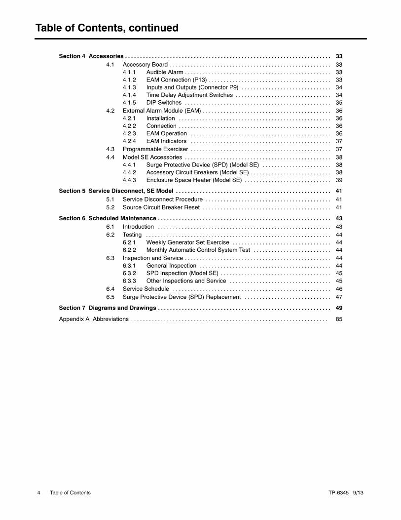
Table of Contents, continued
TP-6345 9/13Table of Contents4
Section 4 Accessories 33. . . . . . . . . . . . . . . . . . . . . . . . . . . . . . . . . . . . . . . . . . . . . . . . . . . . . . . . . . . . . . . . . . . . .
4.1 Accessory Board 33. . . . . . . . . . . . . . . . . . . . . . . . . . . . . . . . . . . . . . . . . . . . . . . . . . . . . .
4.1.1 Audible Alarm 33. . . . . . . . . . . . . . . . . . . . . . . . . . . . . . . . . . . . . . . . . . . . . . . . .
4.1.2 EAM Connection (P13) 33. . . . . . . . . . . . . . . . . . . . . . . . . . . . . . . . . . . . . . . . .
4.1.3 Inputs and Outputs (Connector P9) 34. . . . . . . . . . . . . . . . . . . . . . . . . . . . . .
4.1.4 Time Delay Adjustment Switches 34. . . . . . . . . . . . . . . . . . . . . . . . . . . . . . . .
4.1.5 DIP Switches 35. . . . . . . . . . . . . . . . . . . . . . . . . . . . . . . . . . . . . . . . . . . . . . . . .
4.2 External Alarm Module (EAM) 36. . . . . . . . . . . . . . . . . . . . . . . . . . . . . . . . . . . . . . . . . . .
4.2.1 Installation 36. . . . . . . . . . . . . . . . . . . . . . . . . . . . . . . . . . . . . . . . . . . . . . . . . . .
4.2.2 Connection 36. . . . . . . . . . . . . . . . . . . . . . . . . . . . . . . . . . . . . . . . . . . . . . . . . . .
4.2.3 EAM Operation 36. . . . . . . . . . . . . . . . . . . . . . . . . . . . . . . . . . . . . . . . . . . . . . .
4.2.4 EAM Indicators 37. . . . . . . . . . . . . . . . . . . . . . . . . . . . . . . . . . . . . . . . . . . . . . .
4.3 Programmable Exerciser 37. . . . . . . . . . . . . . . . . . . . . . . . . . . . . . . . . . . . . . . . . . . . . . .
4.4 Model SE Accessories 38. . . . . . . . . . . . . . . . . . . . . . . . . . . . . . . . . . . . . . . . . . . . . . . . .
4.4.1 Surge Protective Device (SPD) (Model SE) 38. . . . . . . . . . . . . . . . . . . . . . .
4.4.2 Accessory Circuit Breakers (Model SE) 38. . . . . . . . . . . . . . . . . . . . . . . . . . .
4.4.3 Enclosure Space Heater (Model SE) 39. . . . . . . . . . . . . . . . . . . . . . . . . . . . .
Section 5 Service Disconnect, SE Model 41. . . . . . . . . . . . . . . . . . . . . . . . . . . . . . . . . . . . . . . . . . . . . . . . . . . .
5.1 Service Disconnect Procedure 41. . . . . . . . . . . . . . . . . . . . . . . . . . . . . . . . . . . . . . . . . .
5.2 Source Circuit Breaker Reset 41. . . . . . . . . . . . . . . . . . . . . . . . . . . . . . . . . . . . . . . . . . .
Section 6 Scheduled Maintenance 43. . . . . . . . . . . . . . . . . . . . . . . . . . . . . . . . . . . . . . . . . . . . . . . . . . . . . . . . . .
6.1 Introduction 43. . . . . . . . . . . . . . . . . . . . . . . . . . . . . . . . . . . . . . . . . . . . . . . . . . . . . . . . . .
6.2 Testing 44. . . . . . . . . . . . . . . . . . . . . . . . . . . . . . . . . . . . . . . . . . . . . . . . . . . . . . . . . . . . . .
6.2.1 Weekly Generator Set Exercise 44. . . . . . . . . . . . . . . . . . . . . . . . . . . . . . . . .
6.2.2 Monthly Automatic Control System Test 44. . . . . . . . . . . . . . . . . . . . . . . . . .
6.3 Inspection and Service 44. . . . . . . . . . . . . . . . . . . . . . . . . . . . . . . . . . . . . . . . . . . . . . . . .
6.3.1 General Inspection 44. . . . . . . . . . . . . . . . . . . . . . . . . . . . . . . . . . . . . . . . . . . .
6.3.2 SPD Inspection (Model SE) 45. . . . . . . . . . . . . . . . . . . . . . . . . . . . . . . . . . . . .
6.3.3 Other Inspections and Service 45. . . . . . . . . . . . . . . . . . . . . . . . . . . . . . . . . .
6.4 Service Schedule 46. . . . . . . . . . . . . . . . . . . . . . . . . . . . . . . . . . . . . . . . . . . . . . . . . . . . .
6.5 Surge Protective Device (SPD) Replacement 47. . . . . . . . . . . . . . . . . . . . . . . . . . . . .
Section 7 Diagrams and Drawings 49. . . . . . . . . . . . . . . . . . . . . . . . . . . . . . . . . . . . . . . . . . . . . . . . . . . . . . . . . .
Appendix A Abbreviations 85. . . . . . . . . . . . . . . . . . . . . . . . . . . . . . . . . . . . . . . . . . . . . . . . . . . . . . . . . . . . . . . . . .
TP-6345 9/13 5Safety Precautions and Instructions
Safety Precautions and Instructions
IMPORTANT SAFETY INSTRUCTIONS.
Electromechanical equipment,including generator sets, transferswitches,switchgear, andaccessories,
can cause bodily harm and poselife-threatening danger whenimproperly installed, operated, ormaintained. To prevent accidents beaware of potential dangers and actsafely. Read and follow all safety
precautions and instructions. SAVETHESE INSTRUCTIONS.
Thismanual hasseveral typesofsafetyprecautions and instructions: Danger,Warning, Caution, and Notice.
DANGER
Danger indicates the presence of ahazard that will cause severe
personal injury,death, orsubstantialproperty damage.
WARNING
Warning indicates the presence of ahazard that can cause severe
personal injury,death,orsubstantialproperty damage.
CAUTION
Caution indicates the presence of ahazard that will or can cause minor
personal injury or property damage.
NOTICE
Notice communicates installation,operation, or maintenance informationthat is safety related but not hazardrelated.
Safety decals affixed to the equipment
in prominent places alert the operatoror service technician to potentialhazards and explain how to act safely.The decals are shown throughout thispublication to improve operatorrecognition. Replace missing or
damaged decals.
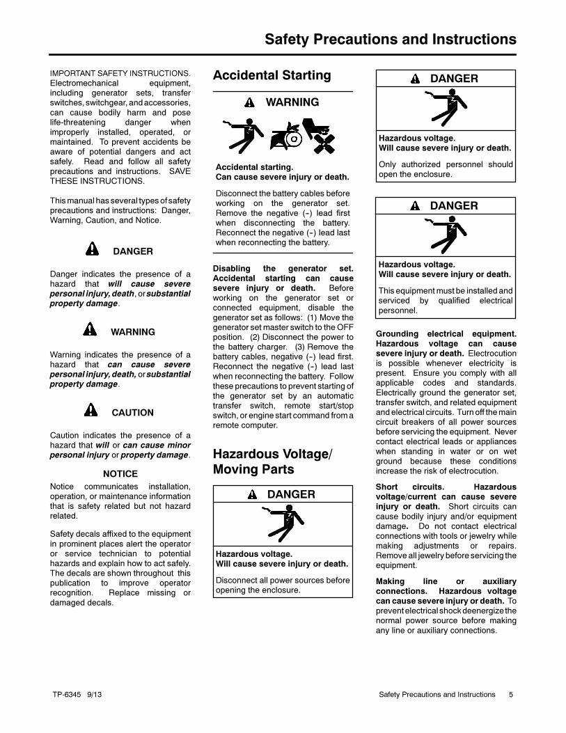
Accidental Starting
Accidental starting.Can cause severe injury or death.
Disconnect the battery cables beforeworking on the generator set.
Remove the negative (--) lead firstwhen disconnecting the battery.Reconnect the negative (--) lead lastwhen reconnecting the battery.
WARNING
Disabling the generator set.Accidental starting can causesevere injury or death. Beforeworking on the generator set orconnected equipment, disable the
generator set as follows: (1) Move thegenerator set master switch to theOFFposition. (2) Disconnect the power tothe battery charger. (3) Remove thebattery cables, negative (--) lead first.Reconnect the negative (--) lead last
when reconnecting the battery. Followthese precautions to prevent starting ofthe generator set by an automatictransfer switch, remote start/stopswitch, or engine start command fromaremote computer.
Hazardous Voltage/Moving Parts
Hazardous voltage.Will cause severe injury or death.
Disconnect all power sources beforeopening the enclosure.
DANGER
Hazardous voltage.Will cause severe injury or death.
Only authorized personnel shouldopen the enclosure.
DANGER
Hazardous voltage.Will cause severe injury or death.
This equipmentmust be installed andserviced by qualified electrical
personnel.
DANGER
Grounding electrical equipment.Hazardous voltage can causesevere injury or death. Electrocutionis possible whenever electricity ispresent. Ensure you comply with allapplicable codes and standards.
Electrically ground the generator set,transfer switch, and related equipmentandelectrical circuits. Turnoff themaincircuit breakers of all power sourcesbefore servicing the equipment. Nevercontact electrical leads or appliances
when standing in water or on wetground because these conditionsincrease the risk of electrocution.
Short circuits. Hazardousvoltage/current can cause severeinjury or death. Short circuits can
cause bodily injury and/or equipmentdamage. Do not contact electricalconnections with tools or jewelry whilemaking adjustments or repairs.Removeall jewelrybefore servicing theequipment.
Making line or auxiliaryconnections. Hazardous voltagecan cause severe injury or death. Topreventelectrical shockdeenergize thenormal power source before making
any line or auxiliary connections.
TP-6345 9/136 Safety Precautions and Instructions
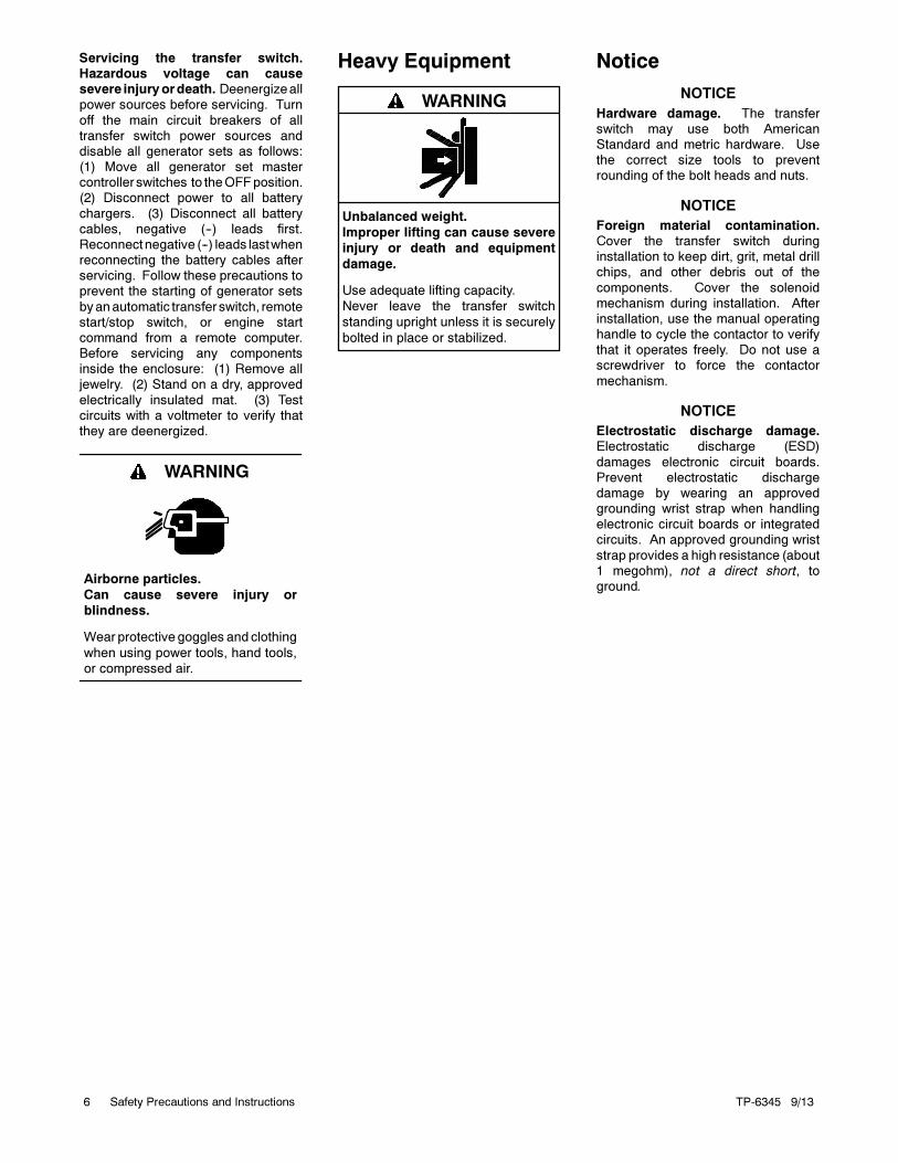
Servicing the transfer switch.Hazardous voltage can causesevere injuryordeath. Deenergizeallpower sources before servicing. Turn
off the main circuit breakers of alltransfer switch power sources anddisable all generator sets as follows:(1) Move all generator set mastercontroller switches to theOFFposition.(2) Disconnect power to all battery
chargers. (3) Disconnect all batterycables, negative (--) leads first.Reconnectnegative (--) leads lastwhenreconnecting the battery cables afterservicing. Follow these precautions toprevent the starting of generator sets
byanautomatic transfer switch, remotestart/stop switch, or engine startcommand from a remote computer.Before servicing any componentsinside the enclosure: (1) Remove alljewelry. (2) Stand on a dry, approved
electrically insulated mat. (3) Testcircuits with a voltmeter to verify thatthey are deenergized.
Airborne particles.
Can cause severe injury or
blindness.
Wear protective goggles and clothing
when using power tools, hand tools,
or compressed air.
WARNING
Heavy Equipment
Unbalanced weight.
Improper lifting can cause severe
injury or death and equipment
damage.
Use adequate lifting capacity.
Never leave the transfer switch
standing upright unless it is securely
bolted in place or stabilized.
WARNING
Notice
NOTICE
Hardware damage. The transferswitch may use both AmericanStandard and metric hardware. Usethe correct size tools to preventrounding of the bolt heads and nuts.
NOTICE
Foreign material contamination.Cover the transfer switch duringinstallation to keep dirt, grit, metal drillchips, and other debris out of the
components. Cover the solenoidmechanism during installation. Afterinstallation, use the manual operatinghandle to cycle the contactor to verifythat it operates freely. Do not use ascrewdriver to force the contactor
mechanism.
NOTICE
Electrostatic discharge damage.Electrostatic discharge (ESD)
damages electronic circuit boards.Prevent electrostatic dischargedamage by wearing an approvedgrounding wrist strap when handlingelectronic circuit boards or integratedcircuits. An approved grounding wrist
strap provides a high resistance (about1 megohm), not a direct short, toground.
TP-6345 9/13 7Introduction
Introduction
This manual provides operation and installation
instructions for Kohler Model RDT automatic transfer
switches with MPAC 500 electrical controls.
Information in this publication represents data available
at the time of print. Kohler Co. reserves the right to
change this literature and the products represented
without notice and without any obligation or liability
whatsoever.
Read this manual and carefully follow all procedures
and safety precautions to ensure proper equipment
operation and to avoid bodily injury. Read and follow the
Safety Precautions and Instructions section at the
beginning of this manual. Keep this manual with the
equipment for future reference.
The equipment service requirements are very important
to safe and efficient operation. Inspect parts often and
perform required service at the prescribed intervals.
Obtain service from an authorized service distributor/
dealer to keep equipment in top condition.
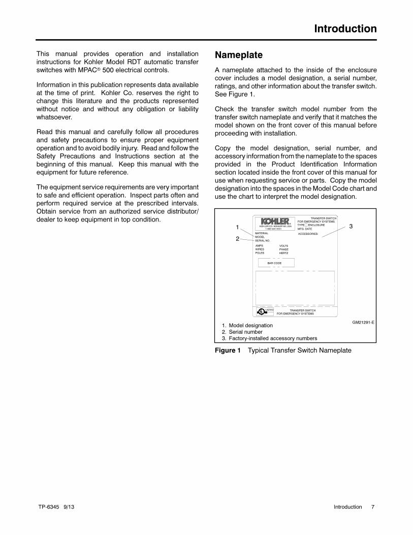
Nameplate
A nameplate attached to the inside of the enclosure
cover includes a model designation, a serial number,
ratings, and other information about the transfer switch.
See Figure 1.
Check the transfer switch model number from the
transfer switch nameplate and verify that it matches the
model shown on the front cover of this manual before
proceeding with installation.
Copy the model designation, serial number, and
accessory information from the nameplate to the spaces
provided in the Product Identification Information
section located inside the front cover of this manual for
use when requesting service or parts. Copy the model
designation into the spaces in theModel Code chart and
use the chart to interpret the model designation.
TRANSFER SWITCH
GM21291-E
1
2
3
1. Model designation
2. Serial number3. Factory-installed accessory numbers
MATERIAL
FOR EMERGENCY SYSTEMS
TRANSFER SWITCH
TYPE ENCLOSURE
MFG. DATE
POLES
WIRES
AMPS
HERTZ
BAR CODE
PHASE
VOLTS
SERIAL NO.
MODEL
ACCESSORIES:
FOR EMERGENCY SYSTEMS
LISTED
R
Figure 1 Typical Transfer Switch Nameplate
TP-6345 9/138 Introduction
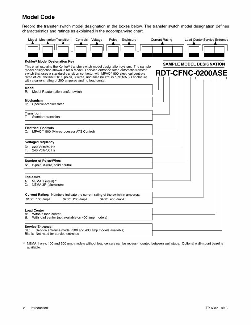
Model Code
Record the transfer switch model designation in the boxes below. The transfer switch model designation defines
characteristics and ratings as explained in the accompanying chart.
Kohler Model Designation Key
This chart explains the Kohler transfer switch model designation system. The samplemodel designation shown is for a Model R service entrance rated automatic transferswitch that uses a standard-transition contactor with MPAC 500 electrical controlsrated at 240 volts/60 Hz, 2 poles, 3 wires, and solid neutral in a NEMA 3R enclosurewith a current rating of 200 amperes and no load center.
ModelR: Model R automatic transfer switch
Electrical ControlsC: MPAC 500 (Microprocessor ATS Control)
Number of Poles/Wires
0100: 100 amps 0200: 200 amps 0400: 400 amps
RDT-CFNC-0200ASE
SAMPLE MODEL DESIGNATION
MechanismD: Specific-breaker rated
TransitionT: Standard transition
Load CenterA: Without load centerB: With load center (not available on 400 amp models)
D: 220 Volts/50 HzF: 240 Volts/60 Hz
Voltage/Frequency
N: 2-pole, 3-wire, solid neutral
Model Controls Voltage Poles Enclosure Current Rating Load CenterMechanismTransition
Current Rating: Numbers indicate the current rating of the switch in amperes:
* NEMA 1 only: 100 and 200 amp models without load centers can be recess-mounted between wall studs. Optional wall-mount bezel isavailable.
Service Entrance:SE: Service entrance model (200 and 400 amp models available)Blank: Not rated for service entrance
Service Entrance
Enclosure
A: NEMA 1 (steel) *C: NEMA 3R (aluminum)
TP-6345 9/13 9Service Assistance
Service Assistance
For professional advice on generator set power
requirements and conscientious service, please contact
your nearest Kohler distributor or dealer.
Consult the Yellow Pages under the heading
Generators—Electric.
Visit the Kohler Power Systems website at
KOHLERPower.com.
Look at the labels and stickers on your Kohler product
or review the appropriate literature or documents
included with the product.
Call toll free in the US and Canada 1-800-544-2444.
Outside the US andCanada, call the nearest regional
office.
Headquarters Europe, Middle East, Africa
(EMEA)
Kohler Power Systems
3 rue de Brennus
93200 Saint Denis
France
Phone: (33) 1 49 178300
Fax: (33) 1 49 178301
Asia Pacific
Power Systems Asia Pacific Regional Office
Singapore, Republic of Singapore
Phone: (65) 6264-6422
Fax: (65) 6264-6455
China
North China Regional Office, Beijing
Phone: (86) 10 6518 7950
(86) 10 6518 7951
(86) 10 6518 7952
Fax: (86) 10 6518 7955
East China Regional Office, Shanghai
Phone: (86) 21 6288 0500
Fax: (86) 21 6288 0550
India, Bangladesh, Sri Lanka
India Regional Office
Bangalore, India
Phone: (91) 80 3366208
(91) 80 3366231
Fax: (91) 80 3315972
Japan, Korea
North Asia Regional Office
Tokyo, Japan
Phone: (813) 3440-4515
Fax: (813) 3440-2727
Latin America
Latin America Regional Office
Lakeland, Florida, USA
Phone: (863) 619-7568
Fax: (863) 701-7131

TP-6345 9/1310 Service Assistance
Notes
TP-6345 9/13 11Section 1 Description
Section 1 Description
1.1 Transfer Switch Description
An automatic transfer switch (ATS) transfers electrical
loads from a normal source of electrical power to an
emergency source when the normal source voltage or
frequency falls below an acceptable level. The normal
source is typically utility power. The emergency source
is usually a generator set.
When the normal source fails, the ATS signals the
emergency source generator set to start. When the
emergency source reaches acceptable levels and
stabilizes, the ATS transfers the electrical load to the
emergency source.
The ATS continuously monitors the normal source and
transfers the load back when the normal source returns
and stabilizes. After transferring the load back to the
normal source, the ATS removes the generator start
signal, allowing the generator set to shut down.
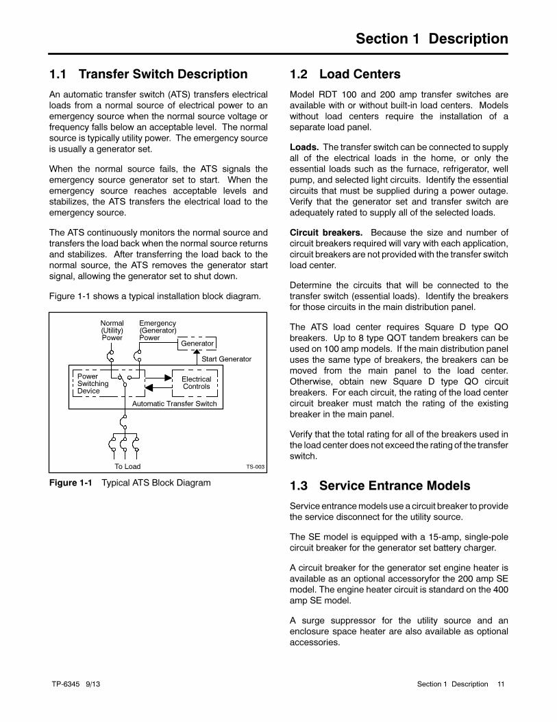
Figure 1-1 shows a typical installation block diagram.
PowerSwitchingDevice
To Load
Automatic Transfer Switch
ElectricalControls
Normal(Utility)Power
Emergency(Generator)Power
Generator
Start Generator
TS-003
Figure 1-1 Typical ATS Block Diagram
1.2 Load Centers
Model RDT 100 and 200 amp transfer switches are
available with or without built-in load centers. Models
without load centers require the installation of a
separate load panel.
Loads. The transfer switch can be connected to supply
all of the electrical loads in the home, or only the
essential loads such as the furnace, refrigerator, well
pump, and selected light circuits. Identify the essential
circuits that must be supplied during a power outage.
Verify that the generator set and transfer switch are
adequately rated to supply all of the selected loads.
Circuit breakers. Because the size and number of
circuit breakers required will vary with each application,
circuit breakers are not provided with the transfer switch
load center.
Determine the circuits that will be connected to the
transfer switch (essential loads). Identify the breakers
for those circuits in the main distribution panel.
The ATS load center requires Square D type QO
breakers. Up to 8 type QOT tandem breakers can be
used on 100 amp models. If the main distribution panel
uses the same type of breakers, the breakers can be
moved from the main panel to the load center.
Otherwise, obtain new Square D type QO circuit
breakers. For each circuit, the rating of the load center
circuit breaker must match the rating of the existing
breaker in the main panel.
Verify that the total rating for all of the breakers used in
the load center does not exceed the rating of the transfer
switch.
1.3 Service Entrance Models
Service entrancemodels use a circuit breaker to provide
the service disconnect for the utility source.
The SE model is equipped with a 15-amp, single-pole
circuit breaker for the generator set battery charger.
A circuit breaker for the generator set engine heater is
available as an optional accessoryfor the 200 amp SE
model. The engine heater circuit is standard on the 400
amp SE model.
A surge suppressor for the utility source and an
enclosure space heater are also available as optional
accessories.

TP-6345 9/1312 Section 1 Description
Notes
TP-6345 9/13 13Section 2 Installation
Section 2 Installation
2.1 Introduction
Kohler transfer switches are shipped factory-wired,
factory-tested, and ready for installation. Have the
equipment installed only by trained and qualified
personnel, and verify that the installation complies with
applicable codes and standards. Protect the switch
against damage before and during installation.
2.2 Receipt of Unit
2.2.1 Inspection
At the time of delivery, inspect the packaging and the
transfer switch for signs of shipping damage. Unpack
the transfer switch as soon as possible and inspect the
exterior and interior for shipping damage. If damage
and/or rough handling is evident, immediately file a
damage claim with the transportation company.
2.2.2 Storage
Store the transfer switch in its protective packing until
final installation. Protect the transfer switch at all times
frommoisture, construction grit, and metal chips. Avoid
storage in cold or damp areas where moisture could
condense on the unit. See Figure 2-1 for acceptable
storage temperatures.
2.2.3 Lifting
Unbalanced weight.
Improper lifting can cause severe
injury or death and equipment
damage.
Use adequate lifting capacity.
Never leave the transfer switch
standing upright unless it is securely
bolted in place or stabilized.
WARNING
See Figure 2-2 or the dimensional drawing for the
weight of the transfer switch. Use a spreader bar to lift
the transfer switch. Attach the bar only to the
enclosure’s mounting holes or lifting brackets; do not lift
the unit any other way. Close and latch the enclosure
door before moving the unit.
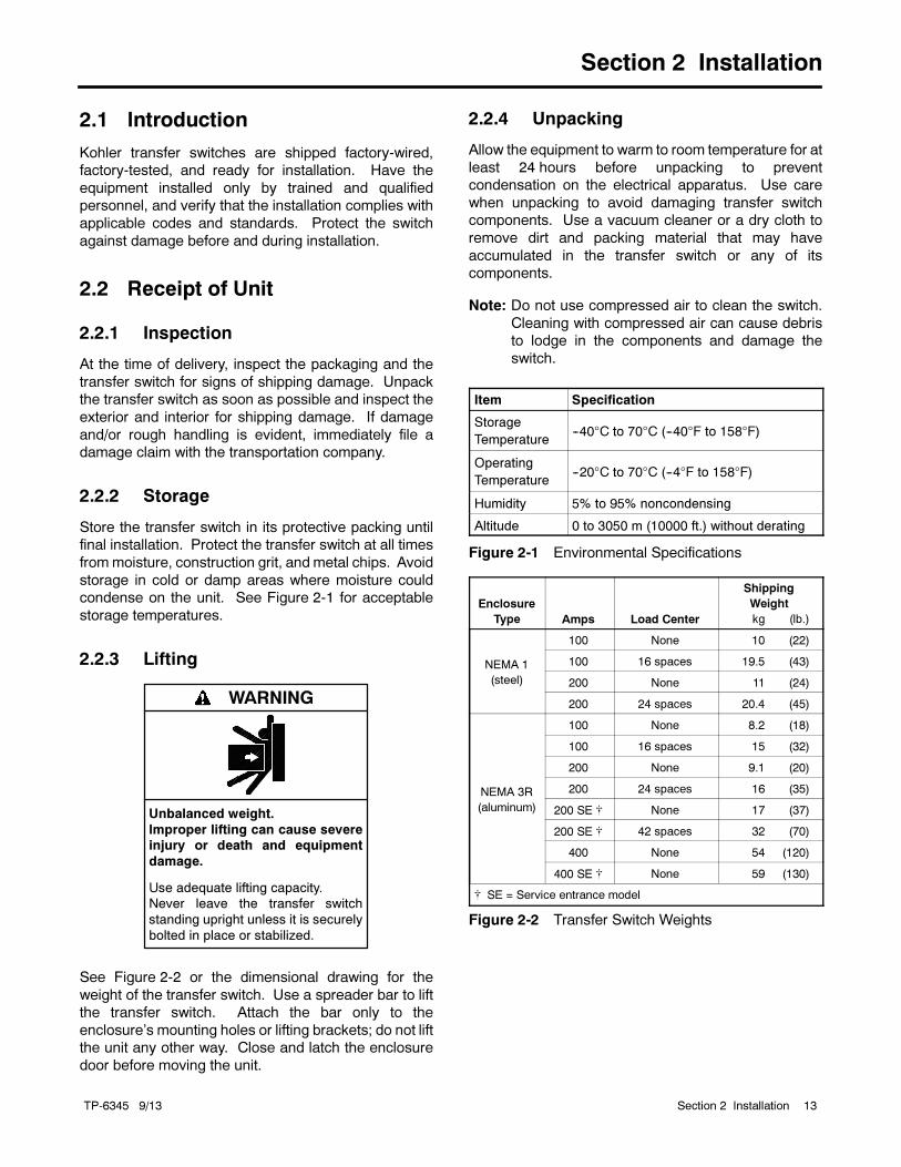
2.2.4 Unpacking
Allow the equipment to warm to room temperature for at
least 24 hours before unpacking to prevent
condensation on the electrical apparatus. Use care
when unpacking to avoid damaging transfer switch
components. Use a vacuum cleaner or a dry cloth to
remove dirt and packing material that may have
accumulated in the transfer switch or any of its
components.
Note: Do not use compressed air to clean the switch.
Cleaning with compressed air can cause debris
to lodge in the components and damage the
switch.
Item Specification
Storage
Temperature--40°C to 70°C (--40°F to 158°F)
Operating
Temperature--20°C to 70°C (--4°F to 158°F)
Humidity 5% to 95% noncondensing
Altitude 0 to 3050 m (10000 ft.) without derating
Figure 2-1 Environmental Specifications
Enclosure
Type Amps Load Center
Shipping
Weight
kg (lb.)
NEMA 1
(steel)
100 None 10 (22)
100 16 spaces 19.5 (43)
200 None 11 (24)
200 24 spaces 20.4 (45)
NEMA 3R
(aluminum)
100 None 8.2 (18)
100 16 spaces 15 (32)
200 None 9.1 (20)
200 24 spaces 16 (35)
200 SE None 17 (37)
200 SE 42 spaces 32 (70)
400 None 54 (120)
400 SE None 59 (130)
SE = Service entrance model
Figure 2-2 Transfer Switch Weights
TP-6345 9/1314 Section 2 Installation
2.3 Installation
NOTICE
Foreign material contamination. Cover the transfer switchduring installation to keep dirt, grit, metal drill chips, and otherdebris out of the components. Cover the solenoidmechanismduring installation. After installation, use themanualoperating
handle to cycle the contactor to verify that it operates freely.Do not use a screwdriver to force the contactor mechanism.
NOTICE
Hardware damage. The transfer switch may use both
AmericanStandard andmetric hardware. Use the correct sizetools to prevent rounding of the bolt heads and nuts.
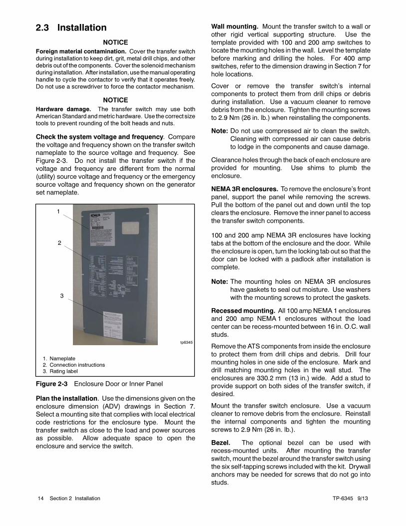
Check the system voltage and frequency. Compare
the voltage and frequency shown on the transfer switch
nameplate to the source voltage and frequency. See
Figure 2-3. Do not install the transfer switch if the
voltage and frequency are different from the normal
(utility) source voltage and frequency or the emergency
source voltage and frequency shown on the generator
set nameplate.
1
tp6345
1. Nameplate
2. Connection instructions3. Rating label
2
3
Figure 2-3 Enclosure Door or Inner Panel
Plan the installation. Use the dimensions given on the
enclosure dimension (ADV) drawings in Section 7.
Select a mounting site that complies with local electrical
code restrictions for the enclosure type. Mount the
transfer switch as close to the load and power sources
as possible. Allow adequate space to open the
enclosure and service the switch.
Wall mounting. Mount the transfer switch to a wall or
other rigid vertical supporting structure. Use the
template provided with 100 and 200 amp switches to
locate themounting holes in thewall. Level the template
before marking and drilling the holes. For 400 amp
switches, refer to the dimension drawing in Section 7 for
hole locations.
Cover or remove the transfer switch’s internal
components to protect them from drill chips or debris
during installation. Use a vacuum cleaner to remove
debris from the enclosure. Tighten themounting screws
to 2.9 Nm (26 in. lb.) when reinstalling the components.
Note: Do not use compressed air to clean the switch.
Cleaning with compressed air can cause debris
to lodge in the components and cause damage.
Clearance holes through the back of each enclosure are
provided for mounting. Use shims to plumb the
enclosure.
NEMA3Renclosures. To remove the enclosure’s front
panel, support the panel while removing the screws.
Pull the bottom of the panel out and down until the top
clears the enclosure. Remove the inner panel to access
the transfer switch components.
100 and 200 amp NEMA 3R enclosures have locking
tabs at the bottom of the enclosure and the door. While
the enclosure is open, turn the locking tab out so that the
door can be locked with a padlock after installation is
complete.
Note: The mounting holes on NEMA 3R enclosures
have gaskets to seal out moisture. Use washers
with the mounting screws to protect the gaskets.
Recessedmounting. All 100 amp NEMA 1 enclosures
and 200 amp NEMA 1 enclosures without the load
center can be recess-mounted between 16 in. O.C. wall
studs.
Remove the ATS components from inside the enclosure
to protect them from drill chips and debris. Drill four
mounting holes in one side of the enclosure. Mark and
drill matching mounting holes in the wall stud. The
enclosures are 330.2 mm (13 in.) wide. Add a stud to
provide support on both sides of the transfer switch, if
desired.
Mount the transfer switch enclosure. Use a vacuum
cleaner to remove debris from the enclosure. Reinstall
the internal components and tighten the mounting
screws to 2.9 Nm (26 in. lb.).
Bezel. The optional bezel can be used with
recess-mounted units. After mounting the transfer
switch,mount the bezel around the transfer switch using
the six self-tapping screws included with the kit. Drywall
anchors may be needed for screws that do not go into
studs.
TP-6345 9/13 15Section 2 Installation
2.4 Manual Operation Check
Hazardous voltage.Will cause severe injury or death.
Disconnect all power sources beforeopening the enclosure.
DANGER
Check the manual operation before energizing the
transfer switch. Verify that the contactor operates
smoothly without binding. Do not place the transfer
switch into service if the contactor does not operate
smoothly.
After checking the manual operation, place the
contactor in the Normal (utility) position.
Manual Operation, 100 and 200 Amp Switches
Note: Never manually operate the transfer switch when
the power is connected. Disconnect both power
sources before manually operating the switch.
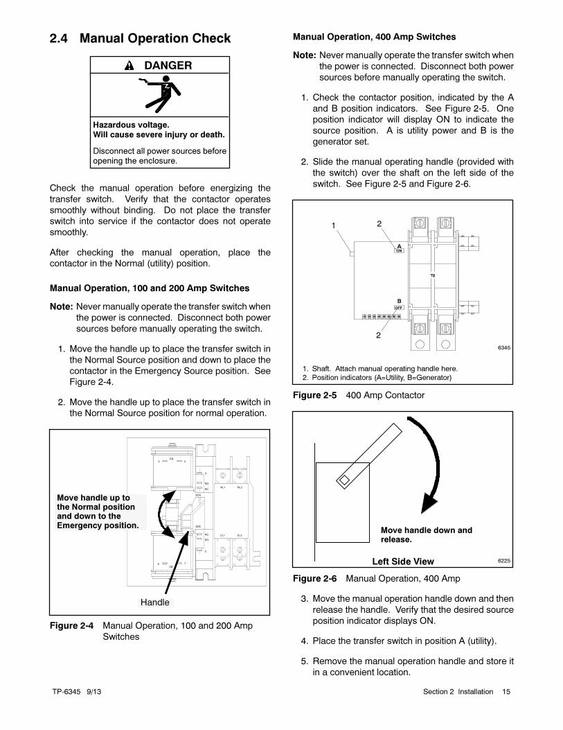
1. Move the handle up to place the transfer switch in
the Normal Source position and down to place the
contactor in the Emergency Source position. See
Figure 2-4.
2. Move the handle up to place the transfer switch in
the Normal Source position for normal operation.
4 3
78
CN
CE
NL1 NL2
EL2EL1
SCN
C
NO
NC
SCE
C
NC
NO
Move handle up tothe Normal positionand down to theEmergency position.
Handle
Figure 2-4 Manual Operation, 100 and 200 Amp
Switches
Manual Operation, 400 Amp Switches
Note: Never manually operate the transfer switch when
the power is connected. Disconnect both power
sources before manually operating the switch.
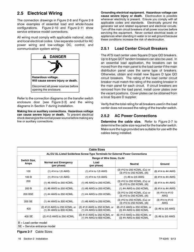
1. Check the contactor position, indicated by the A
and B position indicators. See Figure 2-5. One
position indicator will display ON to indicate the
source position. A is utility power and B is the
generator set.
2. Slide the manual operating handle (provided with
the switch) over the shaft on the left side of the
switch. See Figure 2-5 and Figure 2-6.
1
6345
1. Shaft. Attach manual operating handle here.
2. Position indicators (A=Utility, B=Generator)
A
B
ON
OFF
2
2
Figure 2-5 400 Amp Contactor
6225
Move handle down andrelease.
Left Side View
Figure 2-6 Manual Operation, 400 Amp
3. Move the manual operation handle down and then
release the handle. Verify that the desired source
position indicator displays ON.
4. Place the transfer switch in position A (utility).
5. Remove the manual operation handle and store it
in a convenient location.
TP-6345 9/1316 Section 2 Installation
2.5 Electrical Wiring
The connection drawings in Figure 2-8 and Figure 2-9
show examples of essential load and whole-house
configurations. Figure 2-10 and Figure 2-11 show
service entrance model connections.
All wiring must comply with applicable national, state,
and local electrical codes. Use separate conduit for AC
power wiring and low-voltage DC, control, and
communication system wiring.
Hazardous voltage.Will cause severe injury or death.
Disconnect all power sources beforeopening the enclosure.
DANGER
Refer to the connection diagrams on the transfer switch
enclosure door (see Figure 2-3) and the wiring
diagrams in Section 7 during installation.
Making line or auxiliary connections. Hazardous voltagecan cause severe injury or death. To prevent electricalshockdeenergize thenormalpower sourcebeforemakingany
line or auxiliary connections.
Grounding electrical equipment. Hazardous voltage cancause severe injury or death. Electrocution is possiblewhenever electricity is present. Ensure you comply with allapplicable codes and standards. Electrically ground the
generator set and related equipment and electrical circuits.Turn off the main circuit breakers of all power sources beforeservicing the equipment. Never contact electrical leads orappliances when standing in water or on wet ground becausethese conditions increase the risk of electrocution.
2.5.1 Load Center Circuit Breakers
The ATS load center uses Square D type QO breakers.
Up to 8 typeQOT tandem breakers can also be used. In
an essential load application, the breakers can be
moved from the main panel to the load center if themain
distribution panel uses the same type of breakers.
Otherwise, obtain and install new Square D type QO
circuit breakers. The rating of the load center circuit
breaker must match the rating of the existing breaker in
the main panel for each circuit. If circuit breakers are
removed from the load panel, install cover plates over
the vacant positions. Cover plates can be obtained from
a local Square D supplier.
Verify that the total rating for all breakers used in the load
center does not exceed the rating of the transfer switch.
2.5.2 AC Power Connections
Determine the cable size. Refer to Figure 2-7 to
determine the cable size required for the transfer switch.
Make sure the lugs provided are suitable for use with the
cables being installed.
Cable Sizes
AL/CU UL-Listed Solderless Screw-Type Terminals for External Power Connections
Switch Size,
Amps
Range of Wire Sizes, Cu/Al
Normal and Emergency
(per phase)
Load
(per phase)Neutral Ground
100 (1) #14 to 1/0 AWG (1) #14 to 1/0 AWG(3) #12 to 250 KCMIL (Cu) or
(3) #10 to 250 KCMIL (Al)(9) #14 to #4 AWG
100 B (1) #14 to 1/0 AWG (1) #14 to 1/0 AWG (1) #6 to 2/0 AWG (9) #14 to #4 AWG
200(1) #6 AWG to 250 KCMIL (1) #6 AWG to 250 KCMIL
(3) #12 to 250 KCMIL (Cu) or
(3) #10 to 250 KCMIL (Al)(9) #14 to #4 AWG
200 B (1) #6 AWG to 250 KCMIL (1) #6 AWG to 250 KCMIL (1) #4 AWG to 250 KCMIL (9) #14 to #4 AWG
200 BSE (1) #4 AWG to 250 KCMIL (1) #4 AWG to 250 KCMIL(3) #12 to 250 KCMIL (Cu) or
(3) #10 to 250 KCMIL (Al)
(4) #14 to #1/0
AWG
200 SE (1) #4 AWG to 300 KCMIL (1) #6 AWG to 250 KCMIL(3) #12 to 250 KCMIL (Cu) or
(3) #10 to 250 KCMIL (Al)
(3) #14 to #1/0
AWG
400(2) #1/0 AWG to 250 KCMIL or(1) #4 AWG to 600 KCMIL
(2) #1/0 AWG to 250 KCMIL or(1) #4 AWG to 600 KCMIL
(6) #1/0 AWG to 250 KCMIL or(3) #4 AWG to 600 KCMIL
(3) #6 to 3/0 AWG
400 SE (2) #1/0 AWG to 250 KCMIL(2) #1/0 AWG to 250 KCMIL or(1) #4 AWG to 600 KCMIL
(6) #1/0 AWG to 250 KCMIL or(3) #4 AWG to 600 KCMIL
(3) #6 to 3/0 AWG
B = Load center model
SE = Service entrance model
Figure 2-7 Cable Sizes
TP-6345 9/13 17Section 2 Installation
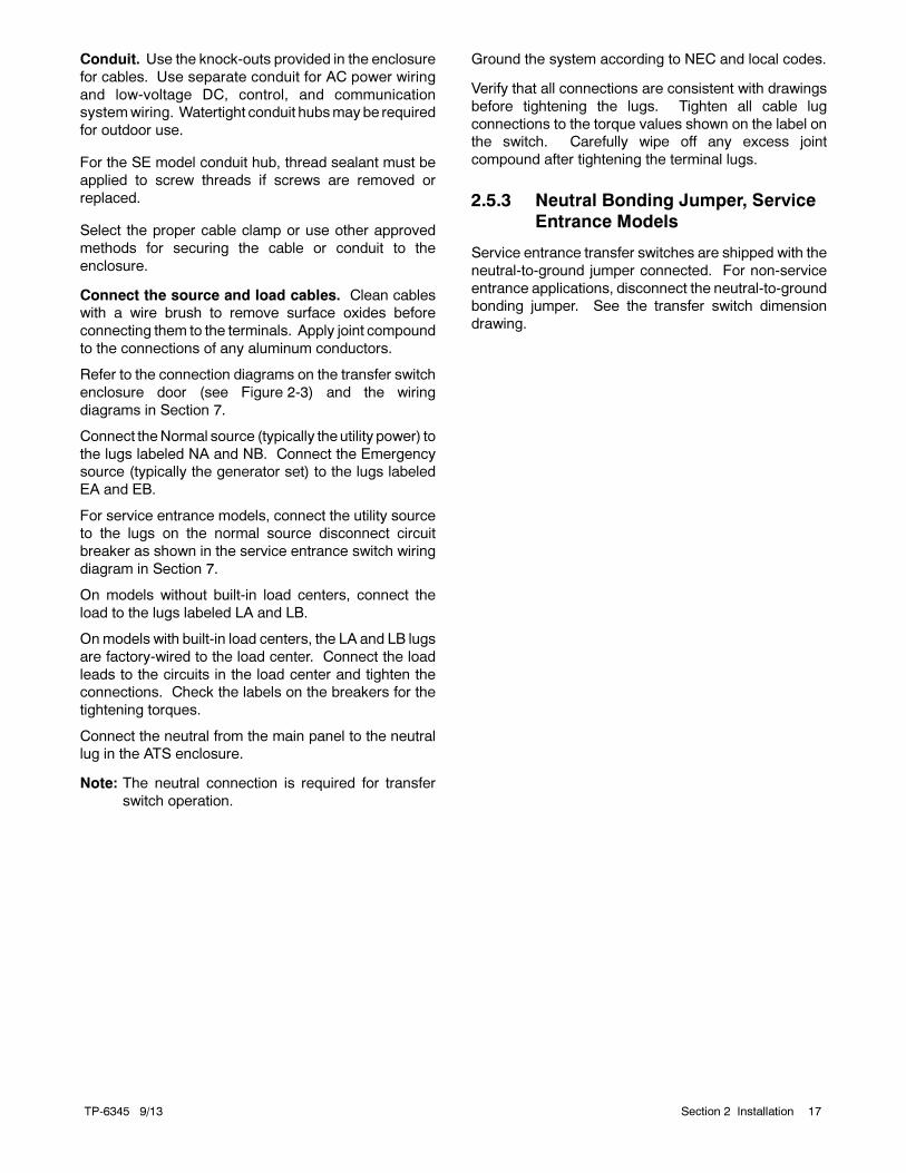
Conduit. Use the knock-outs provided in the enclosure
for cables. Use separate conduit for AC power wiring
and low-voltage DC, control, and communication
systemwiring. Watertight conduit hubsmay be required
for outdoor use.
For the SE model conduit hub, thread sealant must be
applied to screw threads if screws are removed or
replaced.
Select the proper cable clamp or use other approved
methods for securing the cable or conduit to the
enclosure.
Connect the source and load cables. Clean cables
with a wire brush to remove surface oxides before
connecting them to the terminals. Apply joint compound
to the connections of any aluminum conductors.
Refer to the connection diagrams on the transfer switch
enclosure door (see Figure 2-3) and the wiring
diagrams in Section 7.
Connect theNormal source (typically theutility power) to
the lugs labeled NA and NB. Connect the Emergency
source (typically the generator set) to the lugs labeled
EA and EB.
For service entrance models, connect the utility source
to the lugs on the normal source disconnect circuit
breaker as shown in the service entrance switch wiring
diagram in Section 7.
On models without built-in load centers, connect the
load to the lugs labeled LA and LB.
Onmodels with built-in load centers, the LA and LB lugs
are factory-wired to the load center. Connect the load
leads to the circuits in the load center and tighten the
connections. Check the labels on the breakers for the
tightening torques.
Connect the neutral from the main panel to the neutral
lug in the ATS enclosure.
Note: The neutral connection is required for transfer
switch operation.
Ground the system according to NEC and local codes.
Verify that all connections are consistent with drawings
before tightening the lugs. Tighten all cable lug
connections to the torque values shown on the label on
the switch. Carefully wipe off any excess joint
compound after tightening the terminal lugs.
2.5.3 Neutral Bonding Jumper, Service
Entrance Models
Service entrance transfer switches are shipped with the
neutral-to-ground jumper connected. For non-service
entrance applications, disconnect the neutral-to-ground
bonding jumper. See the transfer switch dimension
drawing.
TP-6345 9/1318 Section 2 Installation
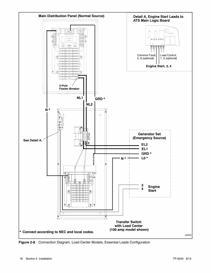
tp6345
Main Distribution Panel (Normal Source)
Generator Set(Emergency Source)
NL2
GRD *
N *
EL1
EL2
2-PoleFeeder Breaker
34
Transfer Switchwith Load Center
(100 amp model shown)
L0 *
GRD *
* Connect according to NEC and local codes.
EngineStart
N *
NL1
See Detail A.
Engine Start, 3, 4
Load Control,1, 2 (optional)
Detail A, Engine Start Leads toATS Main Logic Board
Common Fault,5, 6 (optional)
Figure 2-8 Connection Diagram, Load Center Models, Essential Loads Configuration
TP-6345 9/13 19Section 2 Installation
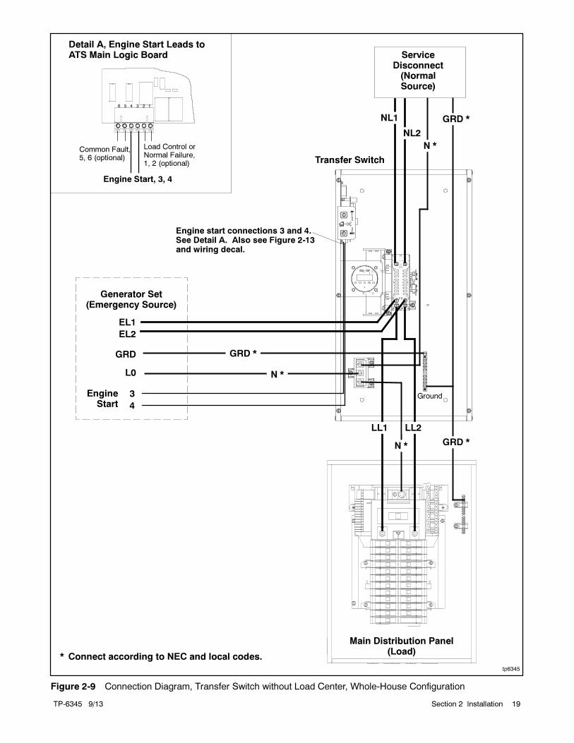
tp6345
Main Distribution Panel(Load)
ServiceDisconnect(NormalSource)
L0
GRD
EngineStart
* Connect according to NEC and local codes.
Generator Set(Emergency Source)
NL1
NL2
GRD *
N *
3
4
GRD *
Transfer Switch
GRD *
N *
LL2LL1
N *
EL1
EL2
Engine start connections 3 and 4.See Detail A. Also see Figure 2-13and wiring decal.
Ground
Engine Start, 3, 4
Load Control orNormal Failure,1, 2 (optional)
Detail A, Engine Start Leads toATS Main Logic Board
Common Fault,5, 6 (optional)
Figure 2-9 Connection Diagram, Transfer Switch without Load Center, Whole-House Configuration
TP-6345 9/1320 Section 2 Installation
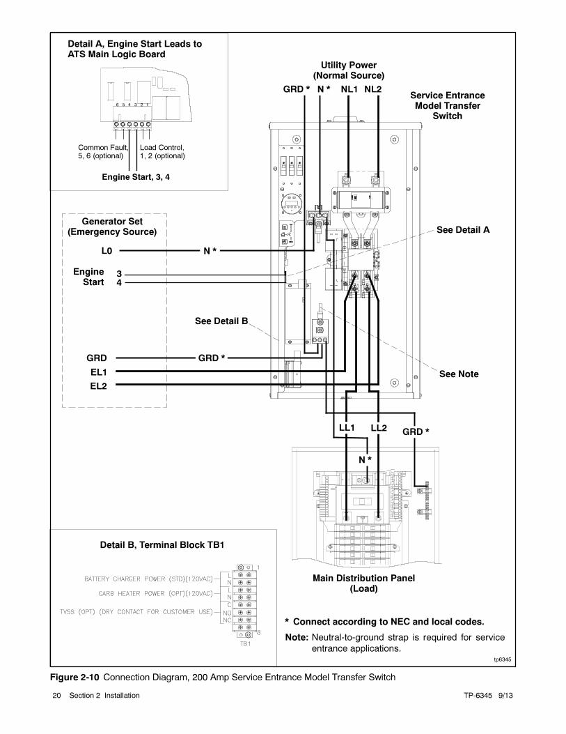
tp6345
Main Distribution Panel(Load)
Utility Power(Normal Source)
L0
EngineStart
* Connect according to NEC and local codes.
Note: Neutral-to-ground strap is required for service
entrance applications.
Generator Set(Emergency Source)
NL1 NL2GRD * N *
EL1
EL2
34
Service EntranceModel Transfer
Switch
N *
LL2LL1
N *
GRD *
Detail B, Terminal Block TB1
GRD
Engine Start, 3, 4
Load Control,1, 2 (optional)
Detail A, Engine Start Leads toATS Main Logic Board
Common Fault,5, 6 (optional)
See Detail B
See Note
See Detail A
GRD *
Figure 2-10 Connection Diagram, 200 Amp Service Entrance Model Transfer Switch
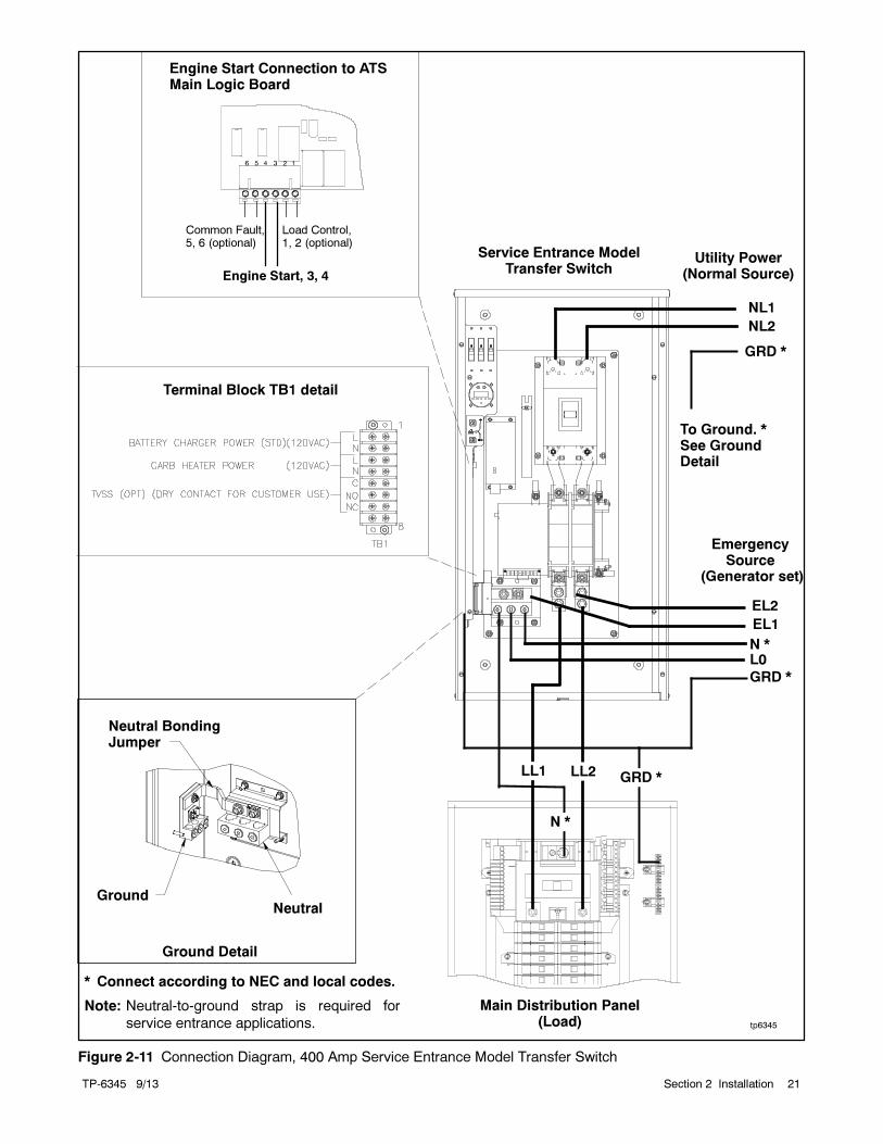
TP-6345 9/13 21Section 2 Installation
tp6345
Main Distribution Panel(Load)
Utility Power(Normal Source)
NL1
NL2
GRD *
N *
EL1
EL2
Service Entrance ModelTransfer Switch
LL2LL1
N *
GRD *
EmergencySource
(Generator set)
Terminal Block TB1 detail
GRD *
Engine Start, 3, 4
Load Control,1, 2 (optional)
Engine Start Connection to ATSMain Logic Board
Common Fault,5, 6 (optional)
L0
* Connect according to NEC and local codes.
Note: Neutral-to-ground strap is required for
service entrance applications.
Neutral BondingJumper
GroundNeutral
Ground Detail
To Ground. *See GroundDetail
Figure 2-11 Connection Diagram, 400 Amp Service Entrance Model Transfer Switch
TP-6345 9/1322 Section 2 Installation
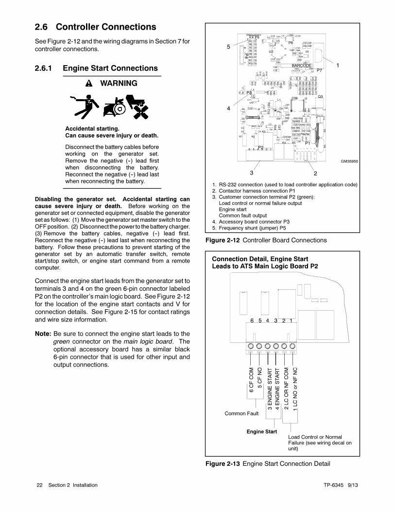
2.6 Controller Connections
See Figure 2-12 and thewiring diagrams in Section 7 for
controller connections.
2.6.1 Engine Start Connections
Accidental starting.Can cause severe injury or death.
Disconnect the battery cables beforeworking on the generator set.
Remove the negative (--) lead firstwhen disconnecting the battery.Reconnect the negative (--) lead lastwhen reconnecting the battery.
WARNING
Disabling the generator set. Accidental starting can
cause severe injury or death. Before working on thegenerator set or connected equipment, disable the generatorset as follows: (1) Move thegenerator setmaster switch to theOFFposition. (2) Disconnect thepower to thebattery charger.(3) Remove the battery cables, negative (--) lead first.Reconnect the negative (--) lead last when reconnecting the
battery. Follow these precautions to prevent starting of thegenerator set by an automatic transfer switch, remotestart/stop switch, or engine start command from a remotecomputer.
Connect the engine start leads from the generator set to
terminals 3 and 4 on the green 6-pin connector labeled
P2 on the controller’smain logic board. SeeFigure 2-12
for the location of the engine start contacts and V for
connection details. See Figure 2-15 for contact ratings
and wire size information.
Note: Be sure to connect the engine start leads to the
green connector on the main logic board. The
optional accessory board has a similar black
6-pin connector that is used for other input and
output connections.
GM35950
1. RS-232 connection (used to load controller application code)
2. Contactor harness connection P13. Customer connection terminal P2 (green):
Load control or normal failure output
Engine startCommon fault output
4. Accessory board connector P3
5. Frequency shunt (jumper) P5
23
BARCODE
6
712
1
P1
R69
R33
C31
C39
+
K2K1
C11 +
VR2
R34
K5
VR1
D7
R36Z1
+
C12
C15
R31
Q3
C26
D18
R68D6
R32
K3
L1
K4
Z2R37
C19
+
Z5
C27
+
C32
D9
D19
C30
D1
R19
+
R70
C13
R47
U1R59
D2
Q2
C50
C5
R11
2212
11
1
44 34
33
23
U2
50
60
P5FREQUENCY +3.3V
GND
+12V
R23
C40
U3
R72
C38
D17
C22C8
C37
C21
R3
R61
C44
R52
R9
R77
C36
U5
R5
C20
C46
R10
R39
R29
R56R16
C47
R58
C14+
C6
R46
D15
R40
C54
R63
C35
C24
R57
R65
R60
R76
R54
C41
R41
R27
R15
R55
C43
R13
R43
Q1
R25
R50
D16
C7
R4
C51
R14
R51
R35
C42
R6
R44
R74
R75
D12
R30
C10 +
C3
D14
C53
D13
C2
C49
R53
R42
C25R18
R7
C28R38
R12
R71
R67
C23
R62
R64
C52
C9
C48
R73
R26
R28
P7
R45R17
C45
C4
R8
P2
R66
6 4
3
P4
1
P6
D8
2
D11
43
1
D10
P3
C29
C34
D5
D3
D4
C55
U4
R24
R22
R21
V4
34
V1
51
8
1
V2
L2
V3
3
16 2
Z3
C18
C1
R48
R20
Y1
R49
C17
R1
C16
Z4
C33
R2
4
1
5
Figure 2-12 Controller Board Connections
Load Control or NormalFailure (see wiring decal onunit)
Connection Detail, Engine StartLeads to ATS Main Logic Board P2
Common Fault
6CFCOM
5CFNO
2LCORNFCOM
1LCNO
orNFNC
3ENGINESTART
4ENGINESTART
Engine Start
Figure 2-13 Engine Start Connection Detail
TP-6345 9/13 23Section 2 Installation
2.6.2 Optional Controller Connections
The green 6-pin connector P2 on the controller’s main
logic board provides connection points for optional
common fault and load control or normal failure circuits.
See Figure 2-12 for the connector location and
Figure 2-13 for connection details. See Figure 2-15 for
contact ratings, connection, and wire size information.
Load Control Contact. Normally open (NO) contact
provided on most models; see the wiring decal on the
unit. Provides a delayed contact closure to allow startup
of selected loads 5 minutes after transfer to the
emergency power source (generator set). Use this
contact to delay startup of equipment with large
motor-starting loads such as air conditioners.
The optional accessory board allows you to change the
load control time delay to 10 minutes. See Section 4.1.
Normal Failure Contact. Normally-closed (NC)
contact provided on models equipped with controller
board GM41597 only; see the wiring diagram decal on
the unit. This contact opens when the normal source is
available and closes when the normal source is lost.
Common Fault Contact. The normally open contact
closes and latches on the following conditions:
Failure to transfer
Position-indicating auxiliary contact fault
Failure to acquire emergency source
Connect customer-supplied equipment such as an
indicator lamp or alarm horn to the common fault
connections on connector P2. See Section 3.3 for fault
information.
The faults must be reset to open this contact after a fault
condition. See Section 3.4 for instructions to reset
faults.
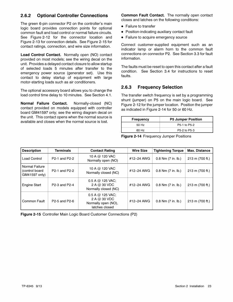
2.6.3 Frequency Selection
The transfer switch frequency is set by a programming
shunt (jumper) on P5 on the main logic board. See
Figure 2-12 for the jumper location. Position the jumper
as indicated in Figure 2-14 for 50 or 60 Hz.
Frequency P5 Jumper Position
50 Hz P5-1 to P5-2
60 Hz P5-2 to P5-3
Figure 2-14 Frequency Jumper Positions
Description Terminals Contact Rating Wire Size Tightening Torque Max. Distance
Load Control P2-1 and P2-210 A @ 120 VAC
Normally open (NO)#12--24 AWG 0.8 Nm (7 in. lb.) 213 m (700 ft.)
Normal Failure
(control board
GM41597 only)P2-1 and P2-2
10 A @ 120 VAC
Normally closed (NC)#12--24 AWG 0.8 Nm (7 in. lb.) 213 m (700 ft.)
Engine Start P2-3 and P2-4
0.5 A @ 125 VAC;
2 A @ 30 VDC
Normally closed (NC)#12--24 AWG 0.8 Nm (7 in. lb.) 213 m (700 ft.)
Common Fault P2-5 and P2-6
0.5 A @ 125 VAC;
2 A @ 30 VDC
Normally open (NO),
latches closed
#12--24 AWG 0.8 Nm (7 in. lb.) 213 m (700 ft.)
Figure 2-15 Controller Main Logic Board Customer Connections (P2)
TP-6345 9/1324 Section 2 Installation
2.7 Accessory Connections
Factory-installed accessories may require power, input,
and output connections. Refer to the following sections
and Section 4 for instructions to connect optional
accessories. Check settings on optional accessories as
described in the following sections.
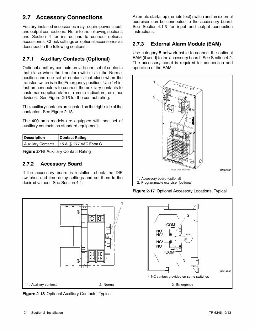
2.7.1 Auxiliary Contacts (Optional)
Optional auxiliary contacts provide one set of contacts
that close when the transfer switch is in the Normal
position and one set of contacts that close when the
transfer switch is in the Emergency position. Use 1/4 in.
fast-on connectors to connect the auxiliary contacts to
customer-supplied alarms, remote indicators, or other
devices. See Figure 2-16 for the contact rating.
The auxiliary contacts are located on the right side of the
contactor. See Figure 2-18.
The 400 amp models are equipped with one set of
auxiliary contacts as standard equipment.
Description Contact Rating
Auxiliary Contacts 15 A @ 277 VAC Form C
Figure 2-16 Auxiliary Contact Rating
2.7.2 Accessory Board
If the accessory board is installed, check the DIP
switches and time delay settings and set them to the
desired values. See Section 4.1.
A remote start/stop (remote test) switch and an external
exerciser can be connected to the accessory board.
See Section 4.1.3 for input and output connection
instructions.
2.7.3 External Alarm Module (EAM)
Use category 5 network cable to connect the optional
EAM (if used) to the accessory board. See Section 4.2.
The accessory board is required for connection and
operation of the EAM.
1
GM82988
1. Accessory board (optional)
2. Programmable exerciser (optional)
2
Figure 2-17 Optional Accessory Locations, Typical
1. Auxiliary contacts 2. Normal 3. Emergency
GM29856
NO
NO
2
3
1
NC*
NC*
COM
COM
* NC contact provided on some switches
Figure 2-18 Optional Auxiliary Contacts, Typical
TP-6345 9/13 25Section 2 Installation
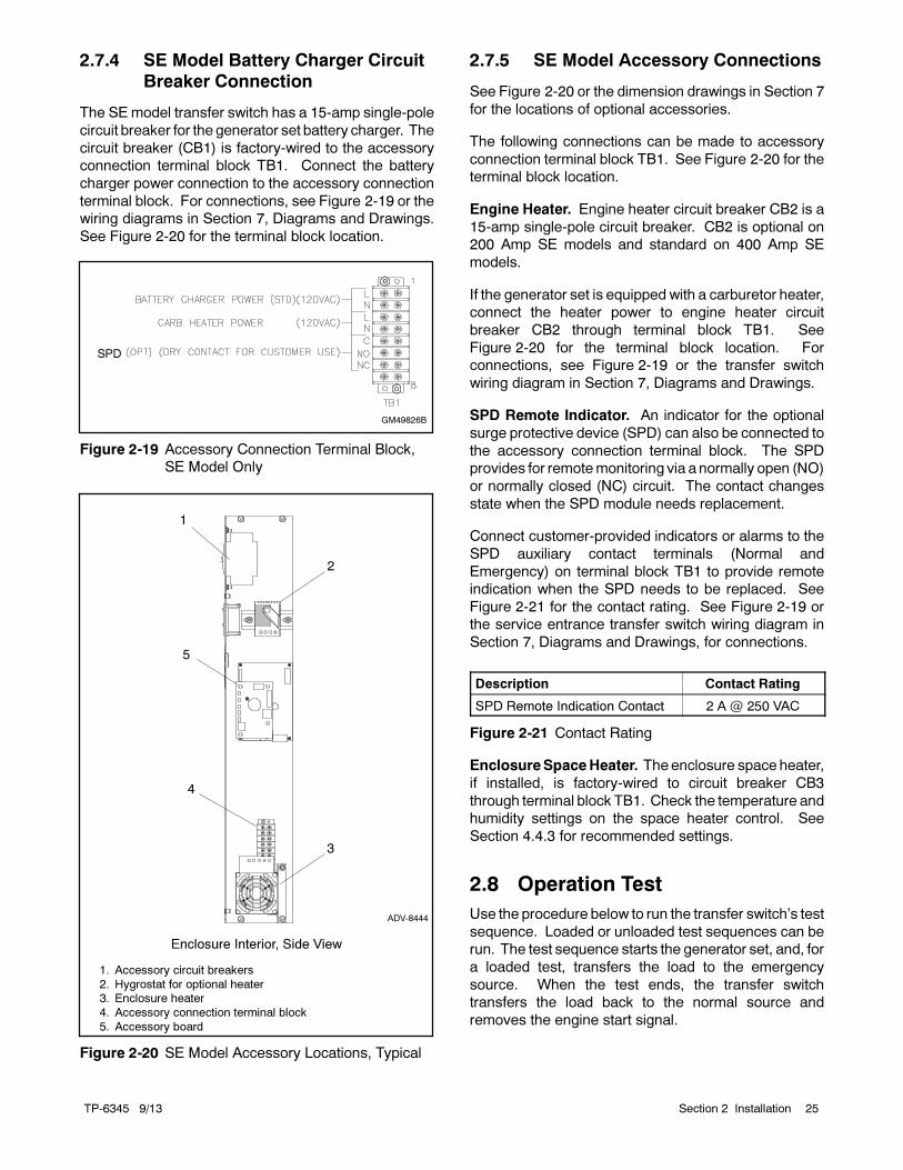
2.7.4 SE Model Battery Charger Circuit
Breaker Connection
The SEmodel transfer switch has a 15-amp single-pole
circuit breaker for the generator set battery charger. The
circuit breaker (CB1) is factory-wired to the accessory
connection terminal block TB1. Connect the battery
charger power connection to the accessory connection
terminal block. For connections, see Figure 2-19 or the
wiring diagrams in Section 7, Diagrams and Drawings.
See Figure 2-20 for the terminal block location.
GM49826B
SPD
Figure 2-19 Accessory Connection Terminal Block,
SE Model Only
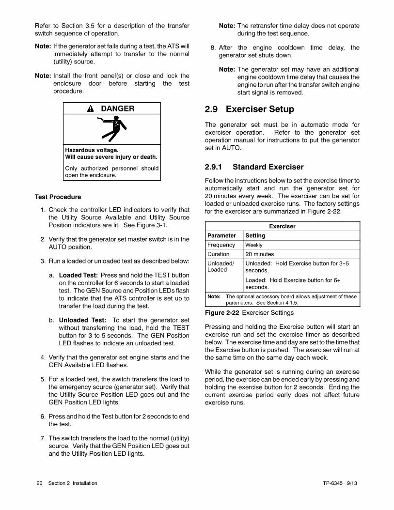
4
ADV-8444
1. Accessory circuit breakers
2. Hygrostat for optional heater3. Enclosure heater
4. Accessory connection terminal block
5. Accessory board
1
Enclosure Interior, Side View
2
3
5
Figure 2-20 SE Model Accessory Locations, Typical
2.7.5 SE Model Accessory Connections
See Figure 2-20 or the dimension drawings in Section 7
for the locations of optional accessories.
The following connections can be made to accessory
connection terminal block TB1. See Figure 2-20 for the
terminal block location.
Engine Heater. Engine heater circuit breaker CB2 is a
15-amp single-pole circuit breaker. CB2 is optional on
200 Amp SE models and standard on 400 Amp SE
models.
If the generator set is equipped with a carburetor heater,
connect the heater power to engine heater circuit
breaker CB2 through terminal block TB1. See
Figure 2-20 for the terminal block location. For
connections, see Figure 2-19 or the transfer switch
wiring diagram in Section 7, Diagrams and Drawings.
SPD Remote Indicator. An indicator for the optional
surge protective device (SPD) can also be connected to
the accessory connection terminal block. The SPD
provides for remotemonitoring via a normally open (NO)
or normally closed (NC) circuit. The contact changes
state when the SPD module needs replacement.
Connect customer-provided indicators or alarms to the
SPD auxiliary contact terminals (Normal and
Emergency) on terminal block TB1 to provide remote
indication when the SPD needs to be replaced. See
Figure 2-21 for the contact rating. See Figure 2-19 or
the service entrance transfer switch wiring diagram in
Section 7, Diagrams and Drawings, for connections.
Description Contact Rating
SPD Remote Indication Contact 2 A @ 250 VAC
Figure 2-21 Contact Rating
EnclosureSpaceHeater. The enclosure space heater,
if installed, is factory-wired to circuit breaker CB3
through terminal block TB1. Check the temperature and
humidity settings on the space heater control. See
Section 4.4.3 for recommended settings.
2.8 Operation Test
Use the procedure below to run the transfer switch’s test
sequence. Loaded or unloaded test sequences can be
run. The test sequence starts the generator set, and, for
a loaded test, transfers the load to the emergency
source. When the test ends, the transfer switch
transfers the load back to the normal source and
removes the engine start signal.
TP-6345 9/1326 Section 2 Installation
Refer to Section 3.5 for a description of the transfer
switch sequence of operation.
Note: If the generator set fails during a test, the ATSwill
immediately attempt to transfer to the normal
(utility) source.
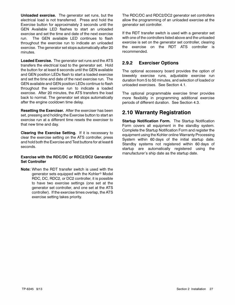
Note: Install the front panel(s) or close and lock the
enclosure door before starting the test
procedure.
Hazardous voltage.Will cause severe injury or death.
Only authorized personnel shouldopen the enclosure.
DANGER
Test Procedure
1. Check the controller LED indicators to verify that
the Utility Source Available and Utility Source
Position indicators are lit. See Figure 3-1.
2. Verify that the generator set master switch is in the
AUTO position.
3. Run a loaded or unloaded test as described below:
a. Loaded Test: Press and hold the TEST button
on the controller for 6 seconds to start a loaded
test. The GEN Source and Position LEDs flash
to indicate that the ATS controller is set up to
transfer the load during the test.
b. Unloaded Test: To start the generator set
without transferring the load, hold the TEST
button for 3 to 5 seconds. The GEN Position
LED flashes to indicate an unloaded test.
4. Verify that the generator set engine starts and the
GEN Available LED flashes.
5. For a loaded test, the switch transfers the load to
the emergency source (generator set). Verify that
the Utility Source Position LED goes out and the
GEN Position LED lights.
6. Press and hold the Test button for 2 seconds to end
the test.
7. The switch transfers the load to the normal (utility)
source. Verify that the GEN Position LED goes out
and the Utility Position LED lights.
Note: The retransfer time delay does not operate
during the test sequence.
8. After the engine cooldown time delay, the
generator set shuts down.
Note: The generator set may have an additional
engine cooldown time delay that causes the
engine to run after the transfer switch engine
start signal is removed.
2.9 Exerciser Setup
The generator set must be in automatic mode for
exerciser operation. Refer to the generator set
operation manual for instructions to put the generator
set in AUTO.
2.9.1 Standard Exerciser
Follow the instructions below to set the exercise timer to
automatically start and run the generator set for
20 minutes every week. The exerciser can be set for
loaded or unloaded exercise runs. The factory settings
for the exerciser are summarized in Figure 2-22.
Exerciser
Parameter Setting
Frequency Weekly
Duration 20 minutes
Unloaded/Loaded
Unloaded: Hold Exercise button for 3--5
seconds.
Loaded: Hold Exercise button for 6+
seconds.
Note: The optional accessory board allows adjustment of these
parameters. See Section 4.1.5.
Figure 2-22 Exerciser Settings
Pressing and holding the Exercise button will start an
exercise run and set the exercise timer as described
below. The exercise time and day are set to the time that
the Exercise button is pushed. The exerciser will run at
the same time on the same day each week.
While the generator set is running during an exercise
period, the exercise can be ended early by pressing and
holding the exercise button for 2 seconds. Ending the
current exercise period early does not affect future
exercise runs.
TP-6345 9/13 27Section 2 Installation
Unloaded exercise. The generator set runs, but the
electrical load is not transferred. Press and hold the
Exercise button for approximately 3 seconds until the
GEN Available LED flashes to start an unloaded
exercise and set the time and date of the next exercise
run. The GEN available LED continues to flash
throughout the exercise run to indicate an unloaded
exercise. The generator set stops automatically after 20
minutes.
Loaded Exercise. The generator set runs and the ATS
transfers the electrical load to the generator set. Hold
the button for at least 6 seconds until the GEN available
and GEN position LEDs flash to start a loaded exercise
and set the time and date of the next exercise run. The
GEN available and GEN position LEDs continue to flash
throughout the exercise run to indicate a loaded
exercise. After 20 minutes, the ATS transfers the load
back to normal. The generator set stops automatically
after the engine cooldown time delay.
Resetting the Exerciser. After the exerciser has been
set, pressing and holding the Exercise button to start an
exercise run at a different time resets the exerciser to
that new time and day.
Clearing the Exercise Setting. If it is necessary to
clear the exercise setting on the ATS controller, press
and hold both the Exercise and Test buttons for at least 6
seconds.
Exercise with the RDC/DC or RDC2/DC2 Generator
Set Controller
Note: When the RDT transfer switch is used with the
generator sets equipped with the Kohler Model
RDC, DC, RDC2, or DC2 controller, it is possible
to have two exercise settings (one set at the
generator set controller, and one set at the ATS
controller). If the exercise times overlap, the ATS
exercise setting takes priority.
The RDC/DC and RDC2/DC2 generator set controllers
allow the programming of an unloaded exercise at the
generator set controller.
If the RDT transfer switch is used with a generator set
with one of the controllers listed above and the unloaded
exercise is set on the generator set controller, clearing
the exercise on the RDT ATS controller is
recommended.
2.9.2 Exerciser Options
The optional accessory board provides the option of
biweekly exercise runs, adjustable exercise run
duration from 5 to 50minutes, and selection of loaded or
unloaded exercises. See Section 4.1.
The optional programmable exercise timer provides
more flexibility in programming additional exercise
periods of different duration. See Section 4.3.
2.10 Warranty Registration
Startup Notification Form. The Startup Notification
Form covers all equipment in the standby system.
Complete the Startup Notification Form and register the
equipment using the Kohler onlineWarranty Processing
System within 60 days of the initial startup date.
Standby systems not registered within 60 days of
startup are automatically registered using the
manufacturer’s ship date as the startup date.

TP-6345 9/1328 Section 2 Installation
Notes
TP-6345 9/13 29Section 3 Operation
Section 3 Operation
3.1 Introduction
Red and green LEDs on the transfer switch controls
indicate which sources are available, show which
source is connected to the load, and flash to indicate
fault conditions. Pushbuttons allow you to start and stop
the generator set and set the exercise timer. See
Figure 3-1.
The transfer switch uses fixed settings for time delays,
voltage and frequency pickup and dropout, and other
system settings. An optional accessory board allows
changes to the time delays and exerciser settings and
provides connections for remote test and remote
exercise inputs. See Section 4.1 for information on the
accessory board.
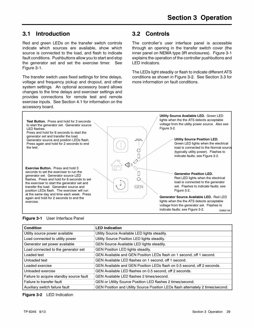
3.2 Controls
The controller’s user interface panel is accessible
through an opening in the transfer switch cover (the
inner panel on NEMA type 3R enclosures). Figure 3-1
explains the operation of the controller pushbuttons and
LED indicators.
The LEDs light steadily or flash to indicate different ATS
conditions as shown in Figure 3-2. See Section 3.3 for
more information on fault conditions.
Generator Source Available LED. Red LED
lights when the the ATS detects acceptable
voltage from the generator set. Flashes to
indicate faults; see Figure 3-2.
Exercise Button. Press and hold 3seconds to set the exerciser to run thegenerator set. Generator source LEDflashes. Press and hold for 6 seconds to setthe exerciser to start the generator set andtransfer the load. Generator source andposition LEDs flash. The exerciser will runat the same day and time each week. Pressagain and hold for 2 seconds to end theexercise.
GM82156
Test Button. Press and hold for 3 secondsto start the generator set. Generator sourceLED flashes.Press and hold for 6 seconds to start thegenerator set and transfer the load.Generator source and position LEDs flash.Press again and hold for 2 seconds to endthe test.
Utility Source Position LED.
Green LED lights when the electrical
load is connected to the Normal source
(typically utility power). Flashes to
indicate faults; see Figure 3-2.
Utility Source Available LED. Green LED
lights when the the ATS detects acceptable
voltage from the utility power source. Also see
Figure 3-2.
Generator Position LED.
Red LED lights when the electrical
load is connected to the generator
set. Flashes to indicate faults; see
Figure 3-2.
Figure 3-1 User Interface Panel
Condition LED Indication
Utility source power available Utility Source Available LED lights steadily.
Load connected to utility power Utility Source Position LED lights steadily.
Generator set power available GEN Source Available LED lights steadily.
Load connected to the generator set GEN Position LED lights steadily.
Loaded test GEN Available and GEN Position LEDs flash on 1 second, off 1 second.
Unloaded test GEN Available LED flashes on 1 second, off 1 second.
Loaded exercise GEN Available and GEN Position LEDs flash on 0.5 second, off 2 seconds.
Unloaded exercise GEN Available LED flashes on 0.5 second, off 2 seconds.
Failure to acquire standby source fault GEN Available LED flashes 2 times/second.
Failure to transfer fault GEN or Utility Source Position LED flashes 2 times/second.
Auxiliary switch failure fault GEN Position and Utility Source Position LEDs flash alternately 2 times/second.
Figure 3-2 LED Indication
TP-6345 9/1330 Section 3 Operation
3.3 Faults
The LEDs on the controller’s user interface flash as
shown in Figure 3-2 to indicate various fault conditions.
Contact an authorized distributor/dealer for service if the
fault persists.
3.3.1 Failure to Acquire Emergency
Source Warning
The Failure to Acquire Emergency Source fault occurs if
the transfer switch does not sense voltage from the
generator set within 78 seconds after signaling the
generator set to start. Check the generator set
operation and the connections from the generator set to
the ATS in the case of this fault.
The Failure to Acquire Emergency Time Delay is set for
78 seconds to allow for three 15-second engine
cranking cycles plus 15 seconds rest between starting
attempts.
The fault clears when the system acquires the
emergency source.
3.3.2 Failure to Transfer Warning
The Failure to Transfer warning occurs if a signal to
transfer is sent to the contactor and the position-
indicating contacts do not indicate a complete transfer.
The controller will attempt to transfer three times before
indicating the fault. If the transfer switch is in the Normal
position, the Engine Cooldown time delay is executed
and then the engine start contacts open to stop the
generator set.
Reset the controller to clear the fault condition. See
Section 3.4.
3.3.3 Auxiliary Switch Fault
An Auxiliary Switch fault occurs if the position-indicating
contacts indicate that the ATS position changed when
no transfer was called for. If the transfer switch is in the
Normal position, the Engine Cooldown time delay is
executed and then the engine start contacts open to
stop the generator set.
An Auxiliary Switch fault also occurs if both auxiliary
switches are open or closed so that the controller is
unable to determine the transfer switch position.
Reset the controller to clear the fault condition. See
Section 3.4.
3.4 Controller Resetting
3.4.1 Fault Reset
Always identify and correct the cause of a fault condition
before resetting the ATS controller. Press and hold the
Exercise and Test buttons for approximately 3 seconds
until the LEDs flash to clear faults and warnings.
Warnings reset automatically with a change in the
source availability or a signal to transfer.
Note: The Common Fault output remains closed until
the faults are reset. See Section 2.6.2.
3.4.2 Controller Reset
Press and hold both buttons for 6 seconds to reset the
controller to its original state at powerup, if necessary.
Note: Resetting the controller clears the exerciser
setting. Set the exercise time and day as
described in Section 2.9 after resetting the
controller.
3.4.3 Alarm Silence
If the transfer switch is equipped with an optional
accessory board, pressing both buttons will also silence
the alarm horn.
3.5 Operation Sequence
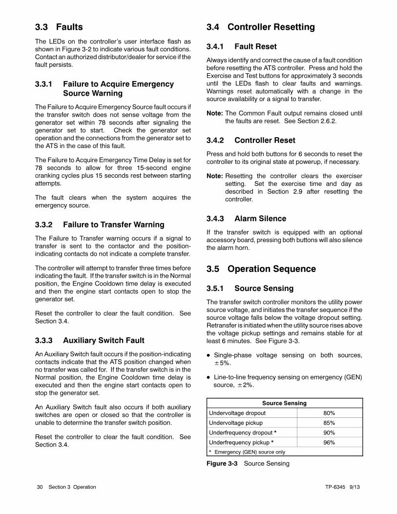
3.5.1 Source Sensing
The transfer switch controller monitors the utility power
source voltage, and initiates the transfer sequence if the
source voltage falls below the voltage dropout setting.
Retransfer is initiatedwhen the utility source rises above
the voltage pickup settings and remains stable for at
least 6 minutes. See Figure 3-3.
Single-phase voltage sensing on both sources,
±5%.
Line-to-line frequency sensing on emergency (GEN)
source, ±2%.
Source Sensing
Undervoltage dropout 80%
Undervoltage pickup 85%
Underfrequency dropout * 90%
Underfrequency pickup * 96%
* Emergency (GEN) source only
Figure 3-3 Source Sensing
TP-6345 9/13 31Section 3 Operation
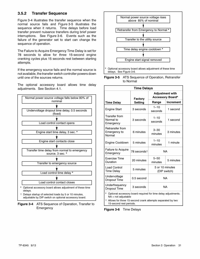
3.5.2 Transfer Sequence
Figure 3-4 illustrates the transfer sequence when the
normal source fails and Figure 3-5 illustrates the
sequence when it returns. Time delays before load
transfer prevent nuisance transfers during brief power
interruptions. See Figure 3-6. Events such as the
failure of the generator set to start can change the
sequence of operation.
The Failure to Acquire Emergency Time Delay is set for
78 seconds to allow for three 15-second engine
cranking cycles plus 15 seconds rest between starting
attempts.
If the emergency source fails and the normal source is
not available, the transfer switch controller powers down
until one of the sources returns.
The optional accessory board allows time delay
adjustments. See Section 4.1.
Transfer time delay from normal to emergencysource, 3 sec. *
Load control time delay *
* Optional accessory board allows adjustment of these timedelays.
Delays startup of selected loads by 5 or 10 minutes,adjustable by DIP switch on optional accessory board.
Engine start time delay, 3 sec. *
Normal power source voltage falls below 80% ofnominal
Undervoltage dropout time delay, 0.5 seconds(fixed)
Transfer to emergency source
Load control contact opens
Engine start contacts close
Load control contact closes
Figure 3-4 ATS Sequence of Operation, Transfer to
Emergency
Retransfer from Emergency to Normal *
Transfer to the utility source
Time delay engine cooldown *
Engine start signal removed
Normal power source voltage risesabove 85% of nominal
* Optional accessory board allows adjustment of these timedelays. See Figure 3-6.
Figure 3-5 ATS Sequence of Operation, Retransfer
to Normal
Time Delays
Time Delay
Factory
Setting
Adjustment with
Accessory Board*
Range Increment
Engine Start 3 seconds1--10
seconds1 second
Transfer from
Normal to
Emergency3 seconds
1--10
seconds1 second
Retransfer from
Emergency to
Normal6 minutes
3--30
minutes3 minutes
Engine Cooldown 5 minutes1--10
minutes1 minute
Failure to Acquire
Emergency78 seconds NA
Exercise Time
Duration20 minutes
5--50
minutes5 minutes
Load Control
Time Delay5 minutes
5 or 10 minutes
(DIP switch)
Undervoltage
Dropout Time0.5 second NA
Underfrequency
Dropout Time3 seconds NA
* Optional accessory board required for time delay adjustments.NA = not adjustable
Allows for three 15-second crank attempts separated by two15-second rest periods.
Figure 3-6 Time Delays

TP-6345 9/1332 Section 3 Operation
Notes
TP-6345 9/13 33Section 4 Accessories
Section 4 Accessories
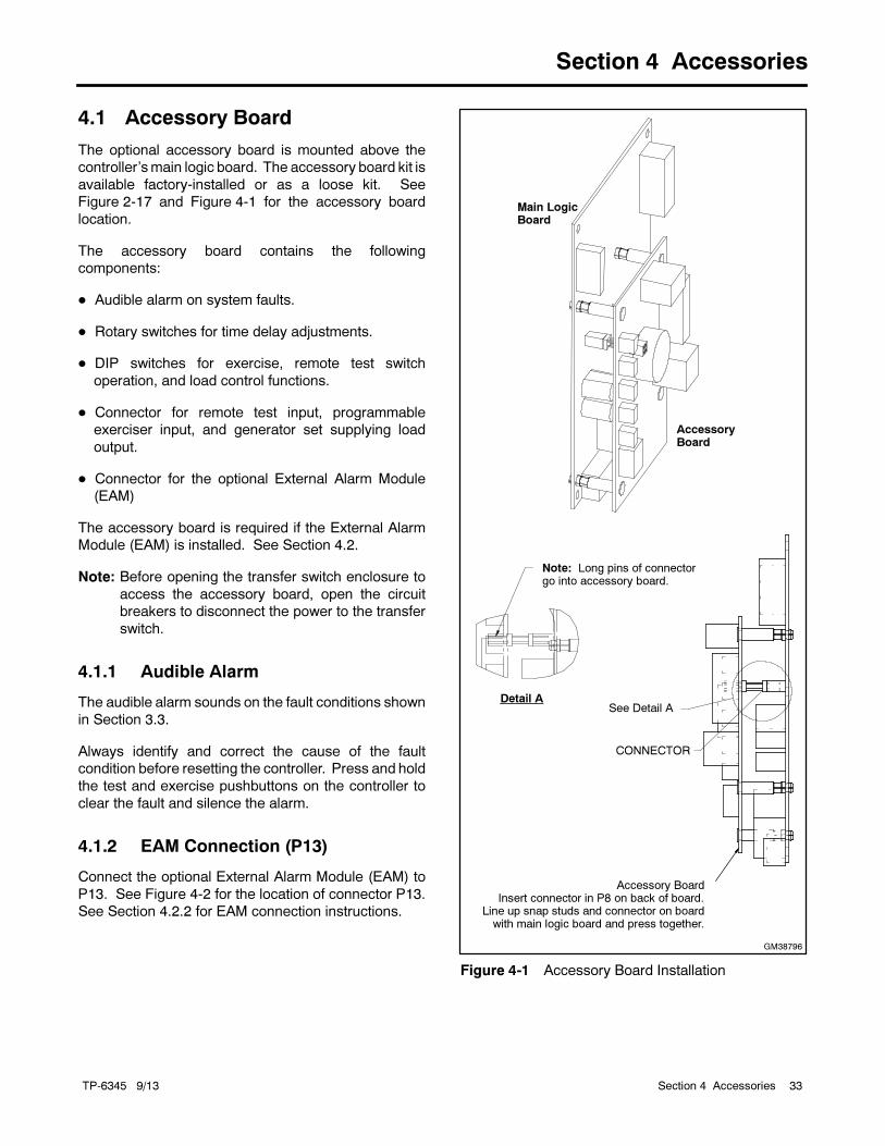
4.1 Accessory Board
The optional accessory board is mounted above the
controller’smain logic board. The accessory board kit is
available factory-installed or as a loose kit. See
Figure 2-17 and Figure 4-1 for the accessory board
location.
The accessory board contains the following
components:
Audible alarm on system faults.
Rotary switches for time delay adjustments.
DIP switches for exercise, remote test switch
operation, and load control functions.
Connector for remote test input, programmable
exerciser input, and generator set supplying load
output.
Connector for the optional External Alarm Module
(EAM)
The accessory board is required if the External Alarm
Module (EAM) is installed. See Section 4.2.
Note: Before opening the transfer switch enclosure to
access the accessory board, open the circuit
breakers to disconnect the power to the transfer
switch.
4.1.1 Audible Alarm
The audible alarm sounds on the fault conditions shown
in Section 3.3.
Always identify and correct the cause of the fault
condition before resetting the controller. Press and hold
the test and exercise pushbuttons on the controller to
clear the fault and silence the alarm.
4.1.2 EAM Connection (P13)
Connect the optional External Alarm Module (EAM) to
P13. See Figure 4-2 for the location of connector P13.
See Section 4.2.2 for EAM connection instructions.
GM38796
Note: Long pins of connectorgo into accessory board.
Detail ASee Detail A
Accessory BoardInsert connector in P8 on back of board.
Line up snap studs and connector on boardwith main logic board and press together.
CONNECTOR
Main LogicBoard
AccessoryBoard
Figure 4-1 Accessory Board Installation
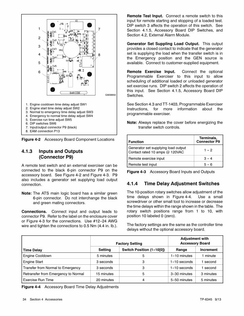
TP-6345 9/1334 Section 4 Accessories
7
GM39650
1. Engine cooldown time delay adjust SW1
2. Engine start time delay adjust SW23. Normal to emergency time delay adjust SW3
4. Emergency to normal time delay adjust SW4
5. Exercise run time adjust SW56. DIP switches SW6
7. Input/output connector P9 (black)
8. EAM connection P13
1
2
3
4
5
6
8
Figure 4-2 Accessory Board Component Locations
4.1.3 Inputs and Outputs
(Connector P9)
A remote test switch and an external exerciser can be
connected to the black 6-pin connector P9 on the
accessory board. See Figure 4-2 and Figure 4-3. P9
also includes a generator set supplying load output
connection.
Note: The ATS main logic board has a similar green
6-pin connector. Do not interchange the black
and green mating connectors.
Connections. Connect input and output leads to
connector P9. Refer to the label on the enclosure cover
or Figure 4-3 for the connections. Use #12--24 AWG
wire and tighten the connections to 0.5 Nm (4.4 in. lb.).
Remote Test Input. Connect a remote switch to this
input for remote starting and stopping of a loaded test.
DIP switch 3 affects the operation of this switch. See
Section 4.1.5, Accessory Board DIP Switches, and
Section 4.2, External Alarm Module.
Generator Set Suppling Load Output. This output
provides a closed contact to indicate that the generator
set is supplying the load when the transfer switch is in
the Emergency position and the GEN source is
available. Connect to customer-supplied equipment.
Remote Exercise Input. Connect the optional
Programmable Exerciser to this input to allow
scheduling of additional loaded or unloaded generator
set exercise runs. DIP switch 2 affects the operation of
this input. See Section 4.1.5, Accessory Board DIP
Switches.
See Section 4.3 and TT-1403, Programmable Exerciser
Instructions, for more information about the
programmable exerciser.
Note: Always replace the cover before energizing the
transfer switch controls.
FunctionTerminals,
Connector P9
Generator set supplying load output
Contact rated 10 amps @ 120VAC1 -- 2
Remote exercise input 3 -- 4
Remote test input 5 -- 6
Figure 4-3 Accessory Board Inputs and Outputs
4.1.4 Time Delay Adjustment Switches
The 10-position rotary switches allow adjustment of the
time delays shown in Figure 4-4. Use a small
screwdriver or other small tool to increase or decrease
the time delays within the range shown in the table. The
rotary switch positions range from 1 to 10, with
position 10 labeled 0 (zero).
The factory settings are the same as the controller time
delays without the optional accessory board.
Time Delay
Factory Setting
Adjustment with
Accessory Board
Setting Switch Position (1--10[0]) Range Increment
Engine Cooldown 5 minutes 5 1--10 minutes 1 minute
Engine Start 3 seconds 3 1--10 seconds 1 second
Transfer from Normal to Emergency 3 seconds 3 1--10 seconds 1 second
Retransfer from Emergency to Normal 15 minutes 5 3--30 minutes 3 minutes
Exercise Run Time 20 minutes 4 5--50 minutes 5 minutes
Figure 4-4 Accessory Board Time Delay Adjustments
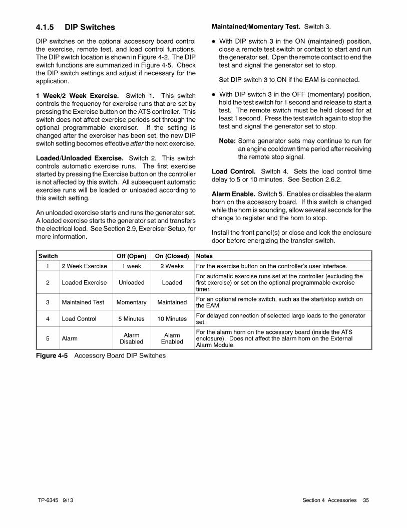
TP-6345 9/13 35Section 4 Accessories
4.1.5 DIP Switches
DIP switches on the optional accessory board control
the exercise, remote test, and load control functions.
The DIP switch location is shown in Figure 4-2. TheDIP
switch functions are summarized in Figure 4-5. Check
the DIP switch settings and adjust if necessary for the
application.
1 Week/2 Week Exercise. Switch 1. This switch
controls the frequency for exercise runs that are set by
pressing the Exercise button on the ATS controller. This
switch does not affect exercise periods set through the
optional programmable exerciser. If the setting is
changed after the exerciser has been set, the new DIP
switch setting becomes effective after the next exercise.
Loaded/Unloaded Exercise. Switch 2. This switch
controls automatic exercise runs. The first exercise
started by pressing the Exercise button on the controller
is not affected by this switch. All subsequent automatic
exercise runs will be loaded or unloaded according to
this switch setting.
An unloaded exercise starts and runs the generator set.
A loaded exercise starts the generator set and transfers
the electrical load. SeeSection 2.9, Exerciser Setup, for
more information.
Maintained/Momentary Test. Switch 3.
With DIP switch 3 in the ON (maintained) position,
close a remote test switch or contact to start and run
the generator set. Open the remote contact to end the
test and signal the generator set to stop.
Set DIP switch 3 to ON if the EAM is connected.
With DIP switch 3 in the OFF (momentary) position,
hold the test switch for 1 second and release to start a
test. The remote switch must be held closed for at
least 1 second. Press the test switch again to stop the
test and signal the generator set to stop.
Note: Some generator sets may continue to run for
an engine cooldown time period after receiving
the remote stop signal.
Load Control. Switch 4. Sets the load control time
delay to 5 or 10 minutes. See Section 2.6.2.
AlarmEnable. Switch 5. Enables or disables the alarm
horn on the accessory board. If this switch is changed
while the horn is sounding, allow several seconds for the
change to register and the horn to stop.
Install the front panel(s) or close and lock the enclosure
door before energizing the transfer switch.
Switch Off (Open) On (Closed) Notes
1 2 Week Exercise 1 week 2 Weeks For the exercise button on the controller’s user interface.
2 Loaded Exercise Unloaded LoadedFor automatic exercise runs set at the controller (excluding thefirst exercise) or set on the optional programmable exercisetimer.
3 Maintained Test Momentary MaintainedFor an optional remote switch, such as the start/stop switch onthe EAM.
4 Load Control 5 Minutes 10 MinutesFor delayed connection of selected large loads to the generatorset.
5 AlarmAlarm
DisabledAlarm
Enabled
For the alarm horn on the accessory board (inside the ATSenclosure). Does not affect the alarm horn on the ExternalAlarm Module.
Figure 4-5 Accessory Board DIP Switches
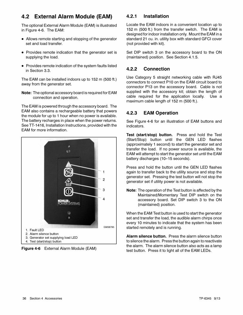
TP-6345 9/1336 Section 4 Accessories
4.2 External Alarm Module (EAM)
The optional External Alarm Module (EAM) is illustrated
in Figure 4-6. The EAM:
Allows remote starting and stopping of the generator
set and load transfer.
Provides remote indication that the generator set is
supplying the load.
Provides remote indication of the system faults listed
in Section 3.3.
The EAM can be installed indoors up to 152 m (500 ft.)
away from the generator set.
Note: The optional accessory board is required for EAM
connection and operation.
The EAM is powered through the accessory board. The
EAM also contains a rechargeable battery that powers
the module for up to 1 hour when no power is available.
The battery recharges in place when the power returns.
See TT-1416, Installation Instructions, provided with the
EAM for more information.
GM38795
1. Fault LED
2. Alarm silence button3. Generator set supplying load LED
4. Test (start/stop) button
3
2
1
4
Figure 4-6 External Alarm Module (EAM)
4.2.1 Installation
Locate the EAM indoors in a convenient location up to
152 m (500 ft.) from the transfer switch. The EAM is
designed for indoor installation only. Mount theEAM in a
standard 21 cu. in. utility box with standard GFCI cover
(not provided with kit).
Set DIP switch 3 on the accessory board to the ON
(maintained) position. See Section 4.1.5.
4.2.2 Connection
Use Category 5 straight networking cable with RJ45
connectors to connect P10 on the EAM circuit board to
connector P13 on the accessory board. Cable is not
supplied with the accessory kit; obtain the length of
cable required for the application locally. Use a
maximum cable length of 152 m (500 ft.).
4.2.3 EAM Operation
See Figure 4-6 for an illustration of EAM buttons and
indicators.
Test (start/stop) button. Press and hold the Test
(Start/Stop) button until the GEN LED flashes
(approximately 1 second) to start the generator set and
transfer the load. If no power source is available, the
EAMwill attempt to start the generator set until the EAM
battery discharges (10--15 seconds).
Press and hold the button until the GEN LED flashes
again to transfer back to the utility source and stop the
generator set. Pressing the test button will not stop the
generator set if utility power is not available.
Note: The operation of the Test button is affected by the
Maintained/Momentary Test DIP switch on the
accessory board. Set DIP switch 3 to the ON
(maintained) position.
When the EAM Test button is used to start the generator
set and transfer the load, the audible alarm chirps once
every 10 minutes to indicate that the system has been
started remotely and is running.
Alarm silence button. Press the alarm silence button
to silence the alarm. Press the button again to reactivate
the alarm. The alarm silence button also acts as a lamp
test button. Press it to light all of the EAM LEDs.
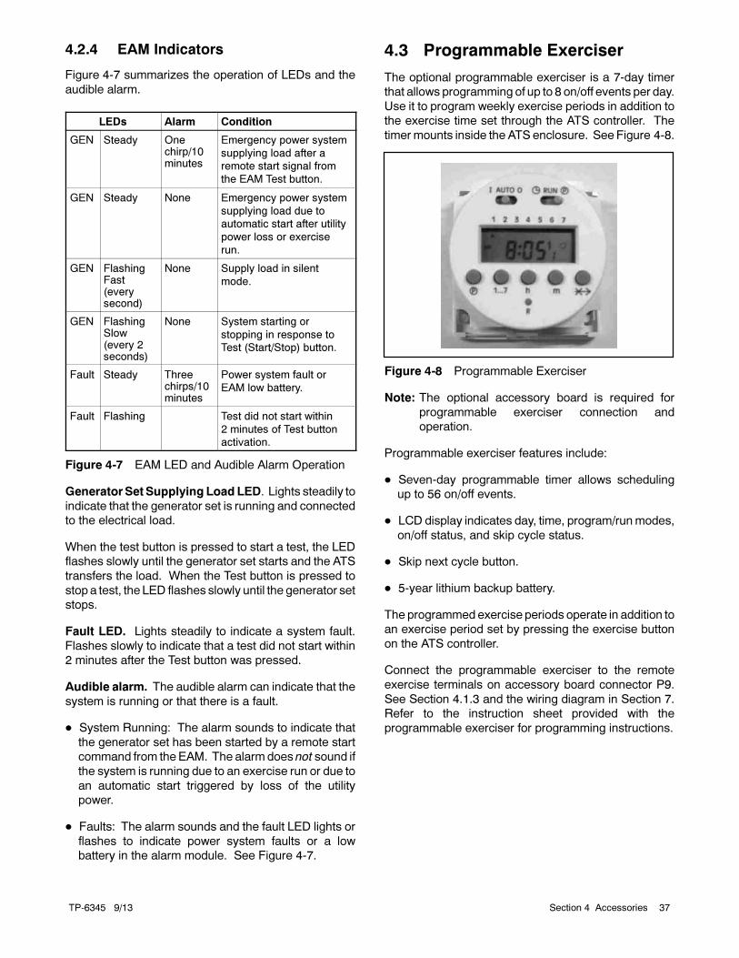
TP-6345 9/13 37Section 4 Accessories
4.2.4 EAM Indicators
Figure 4-7 summarizes the operation of LEDs and the
audible alarm.
LEDs Alarm Condition
GEN Steady Onechirp/10minutes
Emergency power system
supplying load after a
remote start signal from
the EAM Test button.
GEN Steady None Emergency power system
supplying load due to
automatic start after utility
power loss or exercise
run.
GEN FlashingFast(everysecond)
None Supply load in silent
mode.
GEN FlashingSlow(every 2seconds)
None System starting or
stopping in response to
Test (Start/Stop) button.
Fault Steady Threechirps/10minutes
Power system fault or
EAM low battery.
Fault Flashing Test did not start within
2 minutes of Test button
activation.
Figure 4-7 EAM LED and Audible Alarm Operation
Generator Set SupplyingLoadLED. Lights steadily to
indicate that the generator set is running and connected
to the electrical load.
When the test button is pressed to start a test, the LED
flashes slowly until the generator set starts and the ATS
transfers the load. When the Test button is pressed to
stop a test, the LED flashes slowly until the generator set
stops.
Fault LED. Lights steadily to indicate a system fault.
Flashes slowly to indicate that a test did not start within
2 minutes after the Test button was pressed.
Audible alarm. The audible alarm can indicate that the
system is running or that there is a fault.
System Running: The alarm sounds to indicate that
the generator set has been started by a remote start
command from the EAM. The alarm does not sound if
the system is running due to an exercise run or due to
an automatic start triggered by loss of the utility
power.
Faults: The alarm sounds and the fault LED lights or
flashes to indicate power system faults or a low
battery in the alarm module. See Figure 4-7.
4.3 Programmable Exerciser
The optional programmable exerciser is a 7-day timer
that allows programming of up to 8 on/off events per day.
Use it to program weekly exercise periods in addition to
the exercise time set through the ATS controller. The
timer mounts inside the ATS enclosure. See Figure 4-8.
Figure 4-8 Programmable Exerciser
Note: The optional accessory board is required for
programmable exerciser connection and
operation.
Programmable exerciser features include:
Seven-day programmable timer allows scheduling
up to 56 on/off events.
LCD display indicates day, time, program/runmodes,
on/off status, and skip cycle status.
Skip next cycle button.
5-year lithium backup battery.
The programmed exercise periods operate in addition to
an exercise period set by pressing the exercise button
on the ATS controller.
Connect the programmable exerciser to the remote
exercise terminals on accessory board connector P9.
See Section 4.1.3 and the wiring diagram in Section 7.
Refer to the instruction sheet provided with the
programmable exerciser for programming instructions.
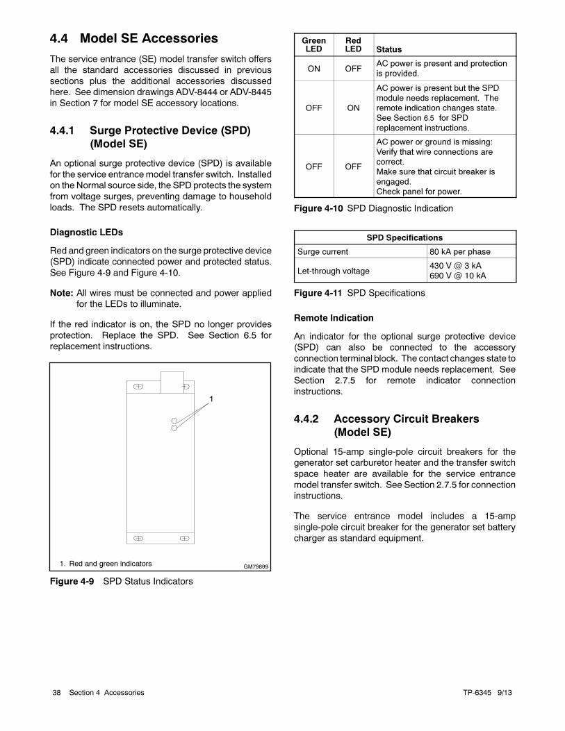
TP-6345 9/1338 Section 4 Accessories
4.4 Model SE Accessories
The service entrance (SE) model transfer switch offers
all the standard accessories discussed in previous
sections plus the additional accessories discussed
here. See dimension drawings ADV-8444 or ADV-8445
in Section 7 for model SE accessory locations.
4.4.1 Surge Protective Device (SPD)
(Model SE)
An optional surge protective device (SPD) is available
for the service entrancemodel transfer switch. Installed
on the Normal source side, the SPDprotects the system
from voltage surges, preventing damage to household
loads. The SPD resets automatically.
Diagnostic LEDs
Red and green indicators on the surge protective device
(SPD) indicate connected power and protected status.
See Figure 4-9 and Figure 4-10.
Note: All wires must be connected and power applied
for the LEDs to illuminate.
If the red indicator is on, the SPD no longer provides
protection. Replace the SPD. See Section 6.5 for
replacement instructions.
1
GM798991. Red and green indicators
Figure 4-9 SPD Status Indicators
GreenLED
RedLED Status
ON OFFAC power is present and protection
is provided.
OFF ON
AC power is present but the SPD
module needs replacement. The
remote indication changes state.
See Section 6.5 for SPD
replacement instructions.
OFF OFF
AC power or ground is missing:
Verify that wire connections are
correct.
Make sure that circuit breaker is
engaged.
Check panel for power.
Figure 4-10 SPD Diagnostic Indication
SPD Specifications
Surge current 80 kA per phase
Let-through voltage430 V @ 3 kA
690 V @ 10 kA
Figure 4-11 SPD Specifications
Remote Indication
An indicator for the optional surge protective device
(SPD) can also be connected to the accessory
connection terminal block. The contact changes state to
indicate that the SPD module needs replacement. See
Section 2.7.5 for remote indicator connection
instructions.
4.4.2 Accessory Circuit Breakers
(Model SE)
Optional 15-amp single-pole circuit breakers for the
generator set carburetor heater and the transfer switch
space heater are available for the service entrance
model transfer switch. See Section 2.7.5 for connection
instructions.
The service entrance model includes a 15-amp
single-pole circuit breaker for the generator set battery
charger as standard equipment.
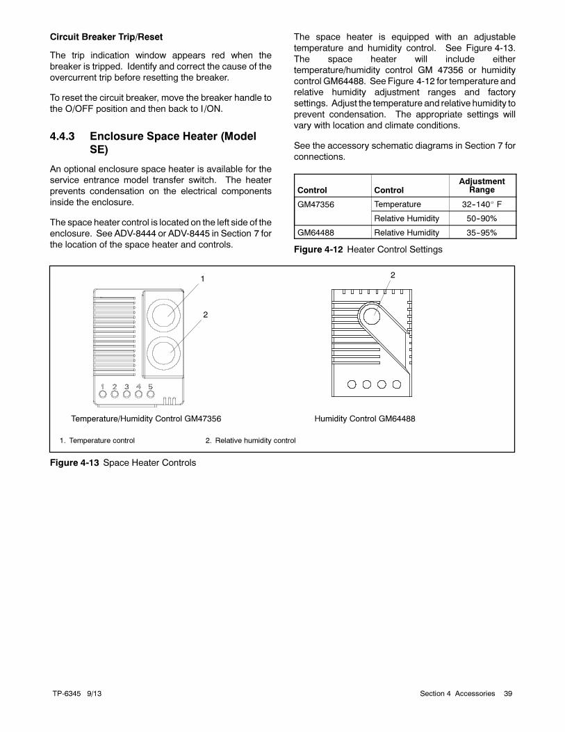
TP-6345 9/13 39Section 4 Accessories
Circuit Breaker Trip/Reset
The trip indication window appears red when the
breaker is tripped. Identify and correct the cause of the
overcurrent trip before resetting the breaker.
To reset the circuit breaker, move the breaker handle to
the O/OFF position and then back to I/ON.
4.4.3 Enclosure Space Heater (Model
SE)
An optional enclosure space heater is available for the
service entrance model transfer switch. The heater
prevents condensation on the electrical components
inside the enclosure.
The space heater control is located on the left side of the
enclosure. See ADV-8444 or ADV-8445 in Section 7 for
the location of the space heater and controls.
The space heater is equipped with an adjustable
temperature and humidity control. See Figure 4-13.
The space heater will include either
temperature/humidity control GM 47356 or humidity
control GM64488. See Figure 4-12 for temperature and
relative humidity adjustment ranges and factory
settings. Adjust the temperature and relative humidity to
prevent condensation. The appropriate settings will
vary with location and climate conditions.
See the accessory schematic diagrams in Section 7 for
connections.
Control ControlAdjustment
Range
GM47356 Temperature 32--140 F
Relative Humidity 50--90%
GM64488 Relative Humidity 35--95%
Figure 4-12 Heater Control Settings
1
1. Temperature control 2. Relative humidity control
2
Temperature/Humidity Control GM47356 Humidity Control GM64488
2
Figure 4-13 Space Heater Controls

TP-6345 9/1340 Section 4 Accessories
Notes
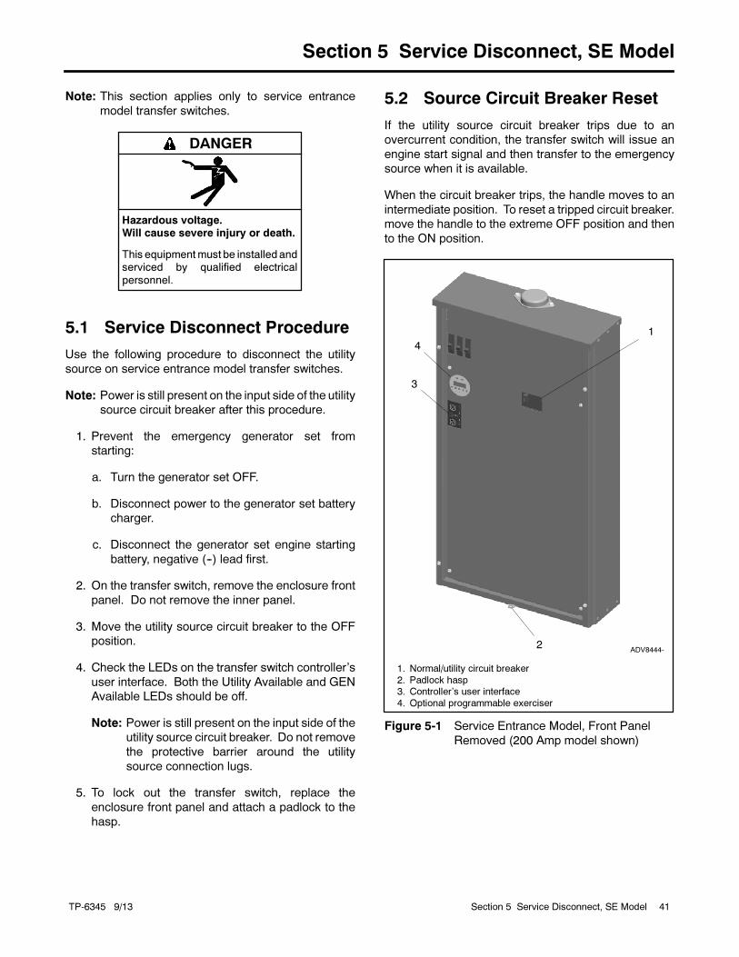
TP-6345 9/13 41Section 5 Service Disconnect, SE Model
Section 5 Service Disconnect, SE Model
Note: This section applies only to service entrance
model transfer switches.
Hazardous voltage.Will cause severe injury or death.
This equipmentmust be installed andserviced by qualified electrical
personnel.
DANGER
5.1 Service Disconnect Procedure
Use the following procedure to disconnect the utility
source on service entrance model transfer switches.
Note: Power is still present on the input side of the utility
source circuit breaker after this procedure.
1. Prevent the emergency generator set from
starting:
a. Turn the generator set OFF.
b. Disconnect power to the generator set battery
charger.
c. Disconnect the generator set engine starting
battery, negative (--) lead first.
2. On the transfer switch, remove the enclosure front
panel. Do not remove the inner panel.
3. Move the utility source circuit breaker to the OFF
position.
4. Check the LEDs on the transfer switch controller’s
user interface. Both the Utility Available and GEN
Available LEDs should be off.
Note: Power is still present on the input side of the
utility source circuit breaker. Do not remove
the protective barrier around the utility
source connection lugs.
5. To lock out the transfer switch, replace the
enclosure front panel and attach a padlock to the
hasp.
5.2 Source Circuit Breaker Reset
If the utility source circuit breaker trips due to an
overcurrent condition, the transfer switch will issue an
engine start signal and then transfer to the emergency
source when it is available.
When the circuit breaker trips, the handle moves to an
intermediate position. To reset a tripped circuit breaker.
move the handle to the extreme OFF position and then
to the ON position.
1
ADV8444-
1. Normal/utility circuit breaker
2. Padlock hasp3. Controller’s user interface
4. Optional programmable exerciser
3
2
4
Figure 5-1 Service Entrance Model, Front Panel
Removed (200 Amp model shown)

TP-6345 9/1342 Section 5 Service Disconnect, SE Model
Notes
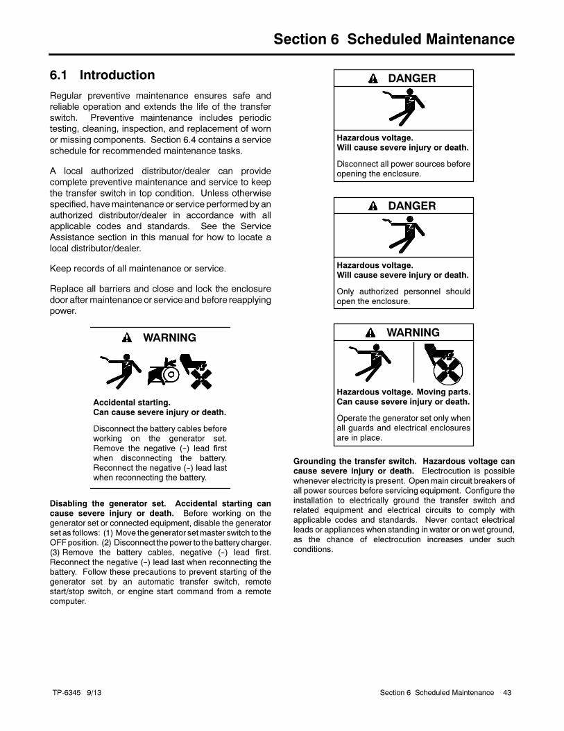
TP-6345 9/13 43Section 6 Scheduled Maintenance
Section 6 Scheduled Maintenance
6.1 Introduction
Regular preventive maintenance ensures safe and
reliable operation and extends the life of the transfer
switch. Preventive maintenance includes periodic
testing, cleaning, inspection, and replacement of worn
or missing components. Section 6.4 contains a service
schedule for recommended maintenance tasks.
A local authorized distributor/dealer can provide
complete preventive maintenance and service to keep
the transfer switch in top condition. Unless otherwise
specified, havemaintenance or service performed by an
authorized distributor/dealer in accordance with all
applicable codes and standards. See the Service
Assistance section in this manual for how to locate a
local distributor/dealer.
Keep records of all maintenance or service.
Replace all barriers and close and lock the enclosure
door aftermaintenance or service and before reapplying
power.
Accidental starting.Can cause severe injury or death.
Disconnect the battery cables beforeworking on the generator set.
Remove the negative (--) lead firstwhen disconnecting the battery.Reconnect the negative (--) lead lastwhen reconnecting the battery.
WARNING
Disabling the generator set. Accidental starting cancause severe injury or death. Before working on thegenerator set or connected equipment, disable the generatorset as follows: (1) Move thegenerator setmaster switch to theOFFposition. (2) Disconnect thepower to thebattery charger.(3) Remove the battery cables, negative (--) lead first.
Reconnect the negative (--) lead last when reconnecting thebattery. Follow these precautions to prevent starting of thegenerator set by an automatic transfer switch, remotestart/stop switch, or engine start command from a remotecomputer.
Hazardous voltage.Will cause severe injury or death.
Disconnect all power sources beforeopening the enclosure.
DANGER
Hazardous voltage.Will cause severe injury or death.
Only authorized personnel shouldopen the enclosure.
DANGER
Hazardous voltage.Can cause severe injury or death.
Operate the generator set only whenall guards and electrical enclosures
are in place.
Moving parts.
WARNING
Grounding the transfer switch. Hazardous voltage cancause severe injury or death. Electrocution is possible
whenever electricity is present. Openmain circuit breakers ofall power sources before servicing equipment. Configure theinstallation to electrically ground the transfer switch andrelated equipment and electrical circuits to comply withapplicable codes and standards. Never contact electricalleads or appliances when standing in water or on wet ground,
as the chance of electrocution increases under suchconditions.
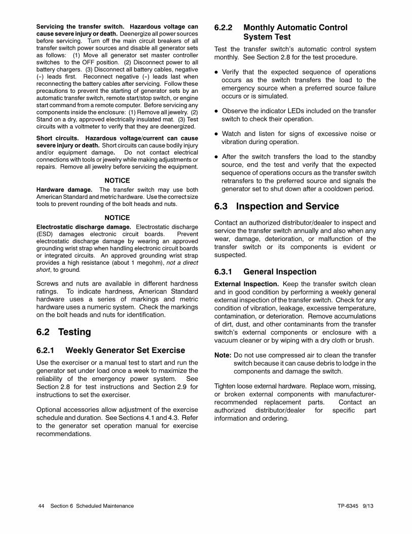
TP-6345 9/1344 Section 6 Scheduled Maintenance
Servicing the transfer switch. Hazardous voltage cancause severe injuryor death. Deenergize all power sourcesbefore servicing. Turn off the main circuit breakers of alltransfer switch power sources and disable all generator sets
as follows: (1) Move all generator set master controllerswitches to the OFF position. (2) Disconnect power to allbattery chargers. (3) Disconnect all battery cables, negative(--) leads first. Reconnect negative (--) leads last whenreconnecting the battery cables after servicing. Follow theseprecautions to prevent the starting of generator sets by an
automatic transfer switch, remote start/stop switch, or enginestart command from a remote computer. Before servicing anycomponents inside the enclosure: (1) Remove all jewelry. (2)Stand on a dry, approved electrically insulated mat. (3) Testcircuits with a voltmeter to verify that they are deenergized.
Short circuits. Hazardous voltage/current can causesevere injury or death. Short circuits can cause bodily injuryand/or equipment damage. Do not contact electricalconnections with tools or jewelry whilemaking adjustments orrepairs. Remove all jewelry before servicing the equipment.
NOTICE
Hardware damage. The transfer switch may use bothAmericanStandard andmetric hardware. Use the correct sizetools to prevent rounding of the bolt heads and nuts.
NOTICE
Electrostatic discharge damage. Electrostatic discharge(ESD) damages electronic circuit boards. Preventelectrostatic discharge damage by wearing an approvedgrounding wrist strap when handling electronic circuit boards
or integrated circuits. An approved grounding wrist strapprovides a high resistance (about 1 megohm), not a direct
short, to ground.
Screws and nuts are available in different hardnessratings. To indicate hardness, American Standardhardware uses a series of markings and metrichardware uses a numeric system. Check the markingson the bolt heads and nuts for identification.
6.2 Testing
6.2.1 Weekly Generator Set Exercise
Use the exerciser or a manual test to start and run the
generator set under load once a week to maximize the
reliability of the emergency power system. See
Section 2.8 for test instructions and Section 2.9 for
instructions to set the exerciser.
Optional accessories allow adjustment of the exercise
schedule and duration. SeeSections 4.1 and 4.3. Refer
to the generator set operation manual for exercise
recommendations.
6.2.2 Monthly Automatic ControlSystem Test
Test the transfer switch’s automatic control system
monthly. See Section 2.8 for the test procedure.
Verify that the expected sequence of operations
occurs as the switch transfers the load to the
emergency source when a preferred source failure
occurs or is simulated.
Observe the indicator LEDs included on the transfer
switch to check their operation.
Watch and listen for signs of excessive noise or
vibration during operation.
After the switch transfers the load to the standby
source, end the test and verify that the expected
sequence of operations occurs as the transfer switch
retransfers to the preferred source and signals the
generator set to shut down after a cooldown period.
6.3 Inspection and Service
Contact an authorized distributor/dealer to inspect and
service the transfer switch annually and also when any
wear, damage, deterioration, or malfunction of the
transfer switch or its components is evident or
suspected.
6.3.1 General Inspection
External Inspection. Keep the transfer switch clean
and in good condition by performing a weekly general
external inspection of the transfer switch. Check for any
condition of vibration, leakage, excessive temperature,
contamination, or deterioration. Remove accumulations
of dirt, dust, and other contaminants from the transfer
switch’s external components or enclosure with a
vacuum cleaner or by wiping with a dry cloth or brush.
Note: Do not use compressed air to clean the transfer
switch because it can cause debris to lodge in the
components and damage the switch.
Tighten loose external hardware. Replace worn, missing,
or broken external components with manufacturer-
recommended replacement parts. Contact an
authorized distributor/dealer for specific part
information and ordering.
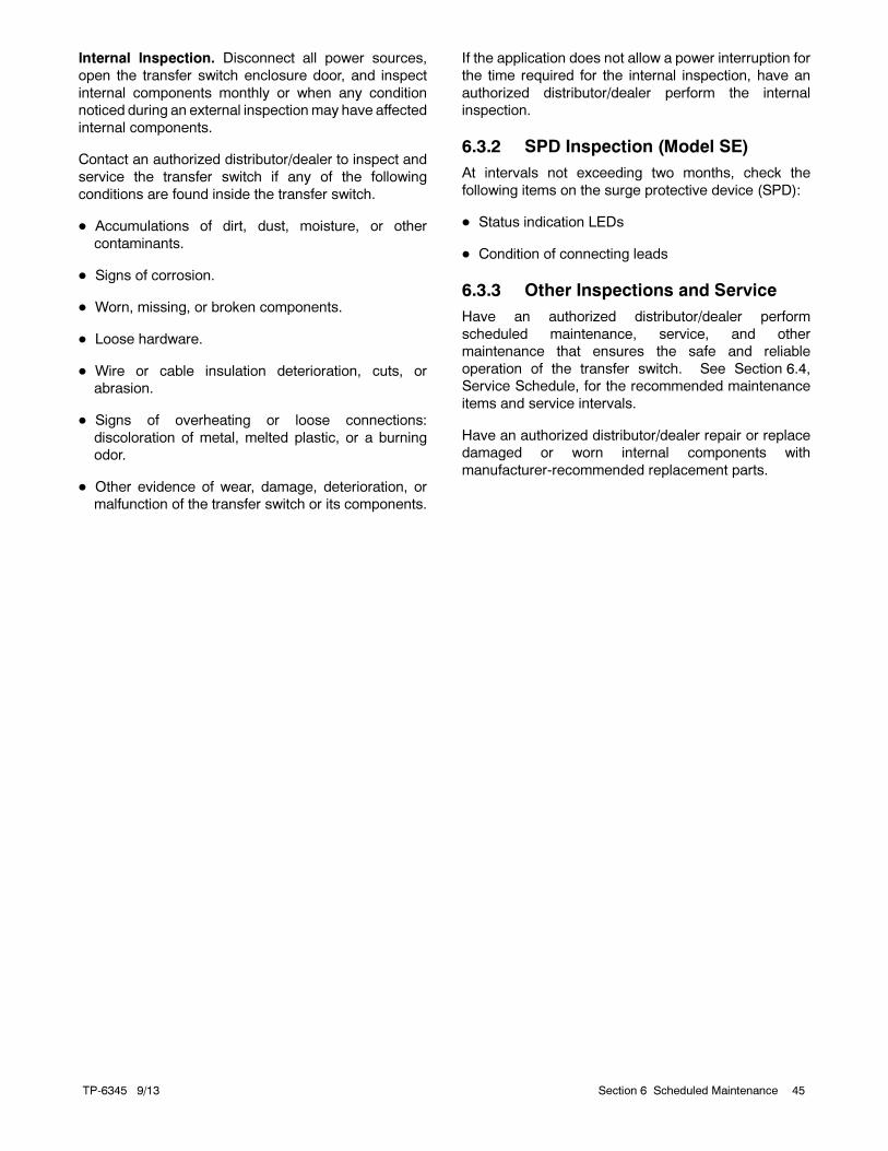
TP-6345 9/13 45Section 6 Scheduled Maintenance
Internal Inspection. Disconnect all power sources,
open the transfer switch enclosure door, and inspect
internal components monthly or when any condition
noticed during an external inspectionmay have affected
internal components.
Contact an authorized distributor/dealer to inspect and
service the transfer switch if any of the following
conditions are found inside the transfer switch.
Accumulations of dirt, dust, moisture, or other
contaminants.
Signs of corrosion.
Worn, missing, or broken components.
Loose hardware.
Wire or cable insulation deterioration, cuts, or
abrasion.
Signs of overheating or loose connections:
discoloration of metal, melted plastic, or a burning
odor.
Other evidence of wear, damage, deterioration, or
malfunction of the transfer switch or its components.
If the application does not allow a power interruption for
the time required for the internal inspection, have an
authorized distributor/dealer perform the internal
inspection.
6.3.2 SPD Inspection (Model SE)
At intervals not exceeding two months, check the
following items on the surge protective device (SPD):
Status indication LEDs
Condition of connecting leads
6.3.3 Other Inspections and Service
Have an authorized distributor/dealer perform
scheduled maintenance, service, and other
maintenance that ensures the safe and reliable
operation of the transfer switch. See Section 6.4,
Service Schedule, for the recommended maintenance
items and service intervals.
Have an authorized distributor/dealer repair or replace
damaged or worn internal components with
manufacturer-recommended replacement parts.
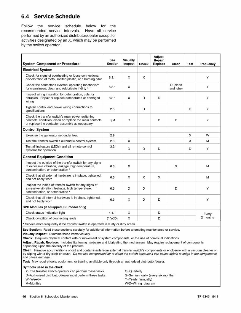
TP-6345 9/1346 Section 6 Scheduled Maintenance
6.4 Service Schedule
Follow the service schedule below for the
recommended service intervals. Have all service
performed by an authorized distributor/dealer except for
activities designated by an X, which may be performed
by the switch operator.
System Component or ProcedureSee
SectionVisuallyInspect Check
Adjust,Repair,Replace Clean Test Frequency
Electrical System
Check for signs of overheating or loose connections:discoloration of metal, melted plastic, or a burning odor
6.3.1 X X Y
Check the contactor’s external operating mechanismfor cleanliness; clean and relubricate if dirty *
6.3.1 XD (cleanand lube)
Y
Inspect wiring insulation for deterioration, cuts, orabrasion. Repair or replace deteriorated or damagedwiring
6.3.1 X D D Y
Tighten control and power wiring connections tospecifications
2.5 D D Y
Check the transfer switch’s main power switchingcontacts’ condition; clean or replace the main contactsor replace the contactor assembly as necessary
S/M D D D Y
Control System
Exercise the generator set under load 2.9 X W
Test the transfer switch’s automatic control system 2.8 X X M
Test all indicators (LEDs) and all remote controlsystems for operation
3.2D D D D Y
General Equipment Condition
Inspect the outside of the transfer switch for any signsof excessive vibration, leakage, high temperature,contamination, or deterioration *
6.3 X X M
Check that all external hardware is in place, tightened,and not badly worn
6.3 X X X M
Inspect the inside of transfer switch for any signs ofexcessive vibration, leakage, high temperature,contamination, or deterioration *
6.3 D D D Y
Check that all internal hardware is in place, tightened,and not badly worn
6.3 X D D Y
SPD Modules (if equipped, SE model only)
Check status indication light 4.4.1 X D Every2 monthsCheck condition of connecting leads 7 (W/D) X D
* Service more frequently if the transfer switch is operated in dusty or dirty areas.
See Section: Read these sections carefully for additional information before attempting maintenance or service.
Visually Inspect: Examine these items visually.
Check: Requires physical contact with or movement of system components, or the use of nonvisual indications.
Adjust, Repair, Replace: Includes tightening hardware and lubricating the mechanism. May require replacement of componentsdepending upon the severity of the problem.
Clean: Remove accumulations of dirt and contaminants from external transfer switch’s components or enclosure with a vacuum cleaner orby wiping with a dry cloth or brush. Do not use compressed air to clean the switch because it can cause debris to lodge in the componentsand cause damage.
Test: May require tools, equipment, or training available only through an authorized distributor/dealer.
Symbols used in the chart:
X=The transfer switch operator can perform these tasks.
D=Authorized distributor/dealer must perform these tasks.
W=Weekly
M=Monthly
Q=Quarterly
S=Semiannually (every six months)
Y=Yearly (annually)
W/D=Wiring diagram
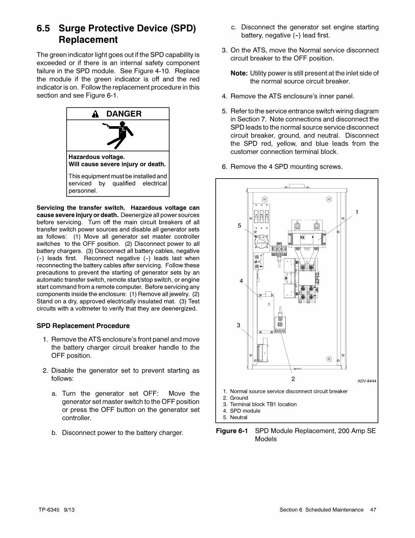
TP-6345 9/13 47Section 6 Scheduled Maintenance
6.5 Surge Protective Device (SPD)
Replacement
The green indicator light goes out if the SPD capability is
exceeded or if there is an internal safety component
failure in the SPD module. See Figure 4-10. Replace
the module if the green indicator is off and the red
indicator is on. Follow the replacement procedure in this
section and see Figure 6-1.
Hazardous voltage.Will cause severe injury or death.
This equipmentmust be installed andserviced by qualified electrical
personnel.
DANGER
Servicing the transfer switch. Hazardous voltage can
cause severe injuryor death. Deenergize all power sourcesbefore servicing. Turn off the main circuit breakers of alltransfer switch power sources and disable all generator setsas follows: (1) Move all generator set master controllerswitches to the OFF position. (2) Disconnect power to allbattery chargers. (3) Disconnect all battery cables, negative
(--) leads first. Reconnect negative (--) leads last whenreconnecting the battery cables after servicing. Follow theseprecautions to prevent the starting of generator sets by anautomatic transfer switch, remote start/stop switch, or enginestart command from a remote computer. Before servicing anycomponents inside the enclosure: (1) Remove all jewelry. (2)
Stand on a dry, approved electrically insulated mat. (3) Testcircuits with a voltmeter to verify that they are deenergized.
SPD Replacement Procedure
1. Remove the ATS enclosure’s front panel andmove
the battery charger circuit breaker handle to the
OFF position.
2. Disable the generator set to prevent starting as
follows:
a. Turn the generator set OFF: Move the
generator setmaster switch to theOFFposition
or press the OFF button on the generator set
controller.
b. Disconnect power to the battery charger.
c. Disconnect the generator set engine starting
battery, negative (--) lead first.
3. On the ATS, move the Normal service disconnect
circuit breaker to the OFF position.
Note: Utility power is still present at the inlet side of
the normal source circuit breaker.
4. Remove the ATS enclosure’s inner panel.
5. Refer to the service entrance switchwiring diagram
in Section 7. Note connections and disconnect the
SPD leads to the normal source service disconnect
circuit breaker, ground, and neutral. Disconnect
the SPD red, yellow, and blue leads from the
customer connection terminal block.
6. Remove the 4 SPD mounting screws.
ADV-8444
1. Normal source service disconnect circuit breaker
2. Ground3. Terminal block TB1 location
4. SPD module
5. Neutral
3
4
1
2
5
Figure 6-1 SPD Module Replacement, 200 Amp SE
Models
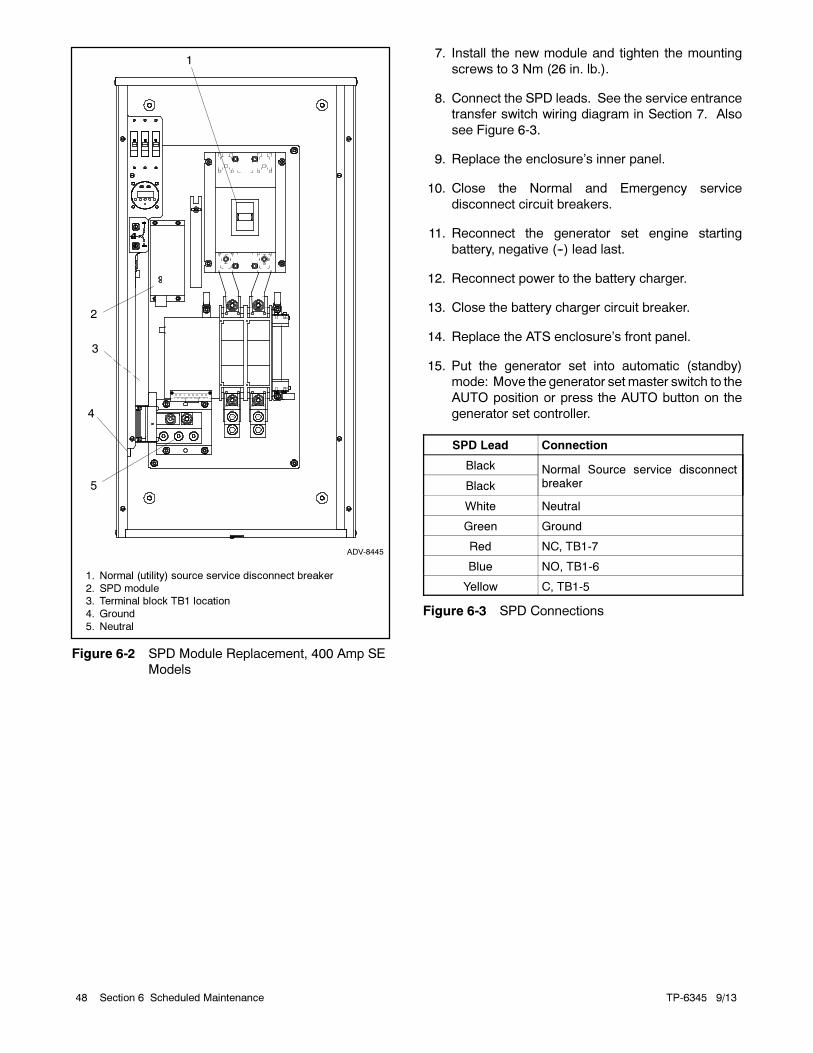
TP-6345 9/1348 Section 6 Scheduled Maintenance
5
3
4
2
ADV-8445
1. Normal (utility) source service disconnect breaker
2. SPD module3. Terminal block TB1 location
4. Ground
5. Neutral
1
Figure 6-2 SPD Module Replacement, 400 Amp SE
Models
7. Install the new module and tighten the mounting
screws to 3 Nm (26 in. lb.).
8. Connect the SPD leads. See the service entrance
transfer switch wiring diagram in Section 7. Also
see Figure 6-3.
9. Replace the enclosure’s inner panel.
10. Close the Normal and Emergency service
disconnect circuit breakers.
11. Reconnect the generator set engine starting
battery, negative (--) lead last.
12. Reconnect power to the battery charger.
13. Close the battery charger circuit breaker.
14. Replace the ATS enclosure’s front panel.
15. Put the generator set into automatic (standby)
mode: Move the generator set master switch to the
AUTO position or press the AUTO button on the
generator set controller.
SPD Lead Connection
Black Normal Source service disconnectbreakerBlack
White Neutral
Green Ground
Red NC, TB1-7
Blue NO, TB1-6
Yellow C, TB1-5
Figure 6-3 SPD Connections
TP-6345 9/13 49Section 7 Diagrams and Drawings
Section 7 Diagrams and Drawings
Drawings are arranged in alphanumeric order on the following pages.
Diagram or Drawing Drawing Number Page
Enclosure Dimensions Drawings
100 Amp NEMA 1 without Load Center ADV-8437-A 52. . . . . . . . . . . . . . . . . . . . . . . . . . . . . . .
100 Amp NEMA 1 with Load Center ADV-8435-A 50. . . . . . . . . . . . . . . . . . . . . . . . . . . . . . . . . .
100 Amp NEMA 3R without Load Center ADV-8440-A 56. . . . . . . . . . . . . . . . . . . . . . . . . . . . . .
100 Amp NEMA 3R with Load Center ADV-8442-A 58. . . . . . . . . . . . . . . . . . . . . . . . . . . . . . . . .
200 Amp NEMA 1 without Load Center ADV-8438-A 53. . . . . . . . . . . . . . . . . . . . . . . . . . . . . . .
200 Amp NEMA1 with Load Center ADV-8436-A 51. . . . . . . . . . . . . . . . . . . . . . . . . . . . . . . . . . .
200 Amp NEMA 3R without Load Center ADV-8441-A 57. . . . . . . . . . . . . . . . . . . . . . . . . . . . . .
200 Amp NEMA 3R with Load Center ADV-8443-A 59. . . . . . . . . . . . . . . . . . . . . . . . . . . . . . . . .
200 Amp NEMA 3R Service Entrance Switch
Sheet 1 ADV-8444-B 60. . . . . . . . . . . . . . . . . . . . . . . . . . . . . . . . . . . . . . . . . . . . . . . . . . . . . . . .
Sheet 2 ADV-8444-B 61. . . . . . . . . . . . . . . . . . . . . . . . . . . . . . . . . . . . . . . . . . . . . . . . . . . . . . . .
200 Amp NEMA 3R Service Entrance Switch with 42-space load center
Sheet 1 ADV-8540 64. . . . . . . . . . . . . . . . . . . . . . . . . . . . . . . . . . . . . . . . . . . . . . . . . . . . . . . .
Sheet 2 ADV-8540 65. . . . . . . . . . . . . . . . . . . . . . . . . . . . . . . . . . . . . . . . . . . . . . . . . . . . . . . .
Sheet 3 ADV-8540 66. . . . . . . . . . . . . . . . . . . . . . . . . . . . . . . . . . . . . . . . . . . . . . . . . . . . . . . .
400 Amp NEMA 3R without Load Center
Sheet 1 ADV-8439-B 54. . . . . . . . . . . . . . . . . . . . . . . . . . . . . . . . . . . . . . . . . . . . . . . . . . . . . . . .
Sheet 2 ADV-8439-B 55. . . . . . . . . . . . . . . . . . . . . . . . . . . . . . . . . . . . . . . . . . . . . . . . . . . . . . . .
400 Amp NEMA 3R Service Entrance Switch
Sheet 1 ADV-8445-B 62. . . . . . . . . . . . . . . . . . . . . . . . . . . . . . . . . . . . . . . . . . . . . . . . . . . . . . . .
Sheet 2 ADV-8445-B 63. . . . . . . . . . . . . . . . . . . . . . . . . . . . . . . . . . . . . . . . . . . . . . . . . . . . . . . .
Schematic Diagrams
100/200 Amp without Load Center GM34466-E 68. . . . . . . . . . . . . . . . . . . . . . . . . . . . . . . . . . . .
100/200 Amp with Load Center GM37649-D 69. . . . . . . . . . . . . . . . . . . . . . . . . . . . . . . . . . . . . .
200 Amp Service Entrance Switch GM84856 82. . . . . . . . . . . . . . . . . . . . . . . . . . . . . . . . . . . .
Accessories GM52482-B 73. . . . . . . . . . . . . . . . . . . . . . . . . . . . . . . . . . . . . . . . . . . . . . . . . . . .
200 Amp Service Entrance Switch with 42-space load center GM83845-A 78. . . . . . . . . . . . .
400 Amp without Load Center GM37651-D 71. . . . . . . . . . . . . . . . . . . . . . . . . . . . . . . . . . . . . . .
400 Amp Service Entrance Switch GM84855 81. . . . . . . . . . . . . . . . . . . . . . . . . . . . . . . . . . . .
Accessories GM65397-C 75. . . . . . . . . . . . . . . . . . . . . . . . . . . . . . . . . . . . . . . . . . . . . . . . . . . .
Wiring Diagrams
100/200 Amp without Load Center GM34465-F 67. . . . . . . . . . . . . . . . . . . . . . . . . . . . . . . . . . . .
100/200 Amp with Load Center GM37650-E 70. . . . . . . . . . . . . . . . . . . . . . . . . . . . . . . . . . . . . .
200 Amp Service Entrance Switch GM84857-B 83. . . . . . . . . . . . . . . . . . . . . . . . . . . . . . . . . . . .
Accessories, Sheet 2 GM84857-B 84. . . . . . . . . . . . . . . . . . . . . . . . . . . . . . . . . . . . . . . . . . . .
200 Amp Service Entrance Switch with 42-space load center GM83844-B 76. . . . . . . . . . . . .
Accessories, Sheet 2 GM83844-B 77. . . . . . . . . . . . . . . . . . . . . . . . . . . . . . . . . . . . . . . . . . . .
400 Amp without Load Center GM37652-E 72. . . . . . . . . . . . . . . . . . . . . . . . . . . . . . . . . . . . . . .
400 Amp Service Entrance Switch GM84854-B 79. . . . . . . . . . . . . . . . . . . . . . . . . . . . . . . . . . . .
Accessories, Sheet 2 GM84854-B 80. . . . . . . . . . . . . . . . . . . . . . . . . . . . . . . . . . . . . . . . . . . .
Programmable Exerciser (Optional) GM64071 74. . . . . . . . . . . . . . . . . . . . . . . . . . . . . . . . . .
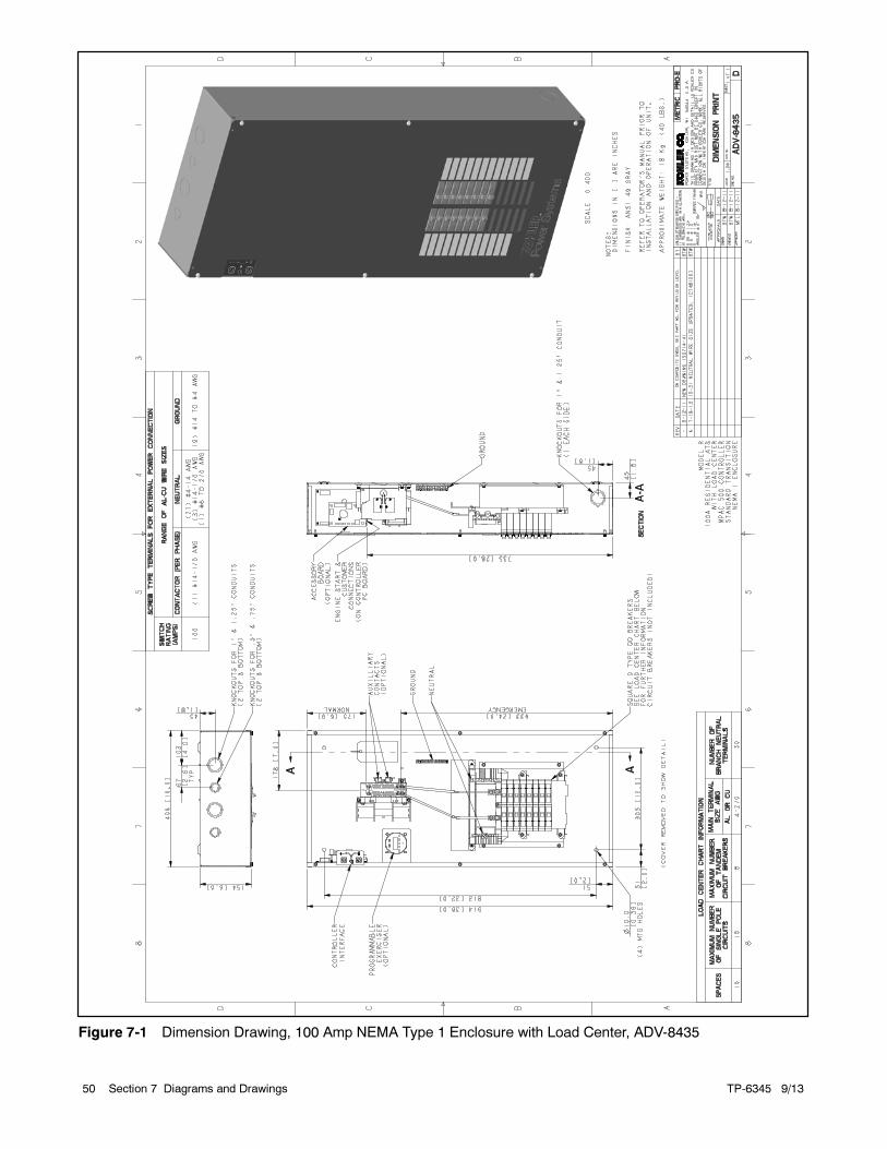
TP-6345 9/1350 Section 7 Diagrams and Drawings
Figure 7-1 Dimension Drawing, 100 Amp NEMA Type 1 Enclosure with Load Center, ADV-8435
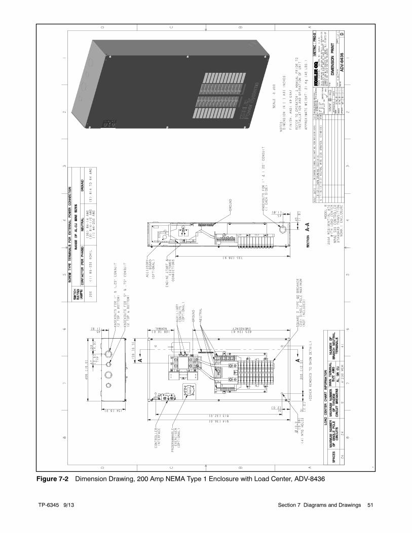
TP-6345 9/13 51Section 7 Diagrams and Drawings
-
Figure 7-2 Dimension Drawing, 200 Amp NEMA Type 1 Enclosure with Load Center, ADV-8436
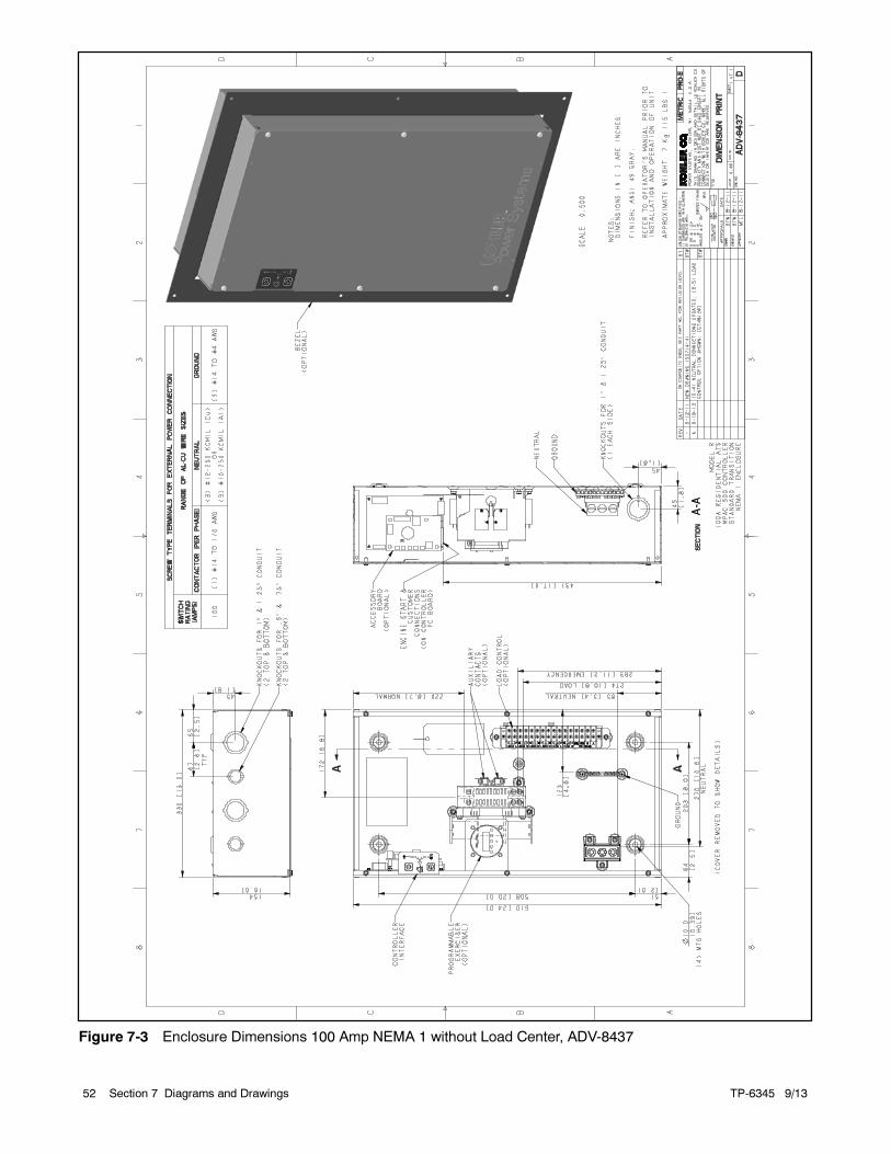
TP-6345 9/1352 Section 7 Diagrams and Drawings
Figure 7-3 Enclosure Dimensions 100 Amp NEMA 1 without Load Center, ADV-8437
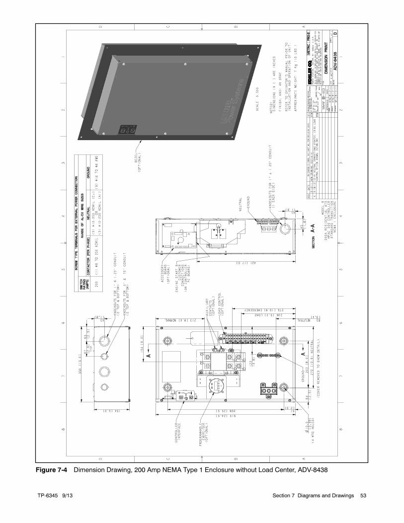
TP-6345 9/13 53Section 7 Diagrams and Drawings
Figure 7-4 Dimension Drawing, 200 Amp NEMA Type 1 Enclosure without Load Center, ADV-8438
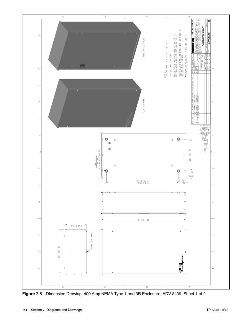
TP-6345 9/1354 Section 7 Diagrams and Drawings
Figure 7-5 Dimension Drawing, 400 Amp NEMA Type 1 and 3R Enclosure, ADV-8439, Sheet 1 of 2
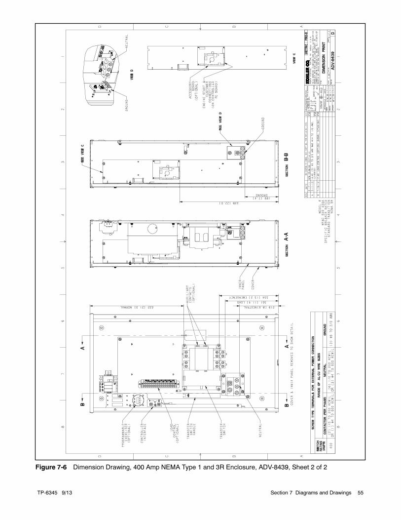
TP-6345 9/13 55Section 7 Diagrams and Drawings
Figure 7-6 Dimension Drawing, 400 Amp NEMA Type 1 and 3R Enclosure, ADV-8439, Sheet 2 of 2
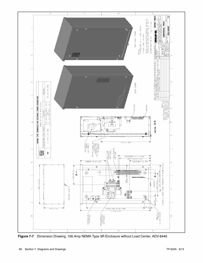
TP-6345 9/1356 Section 7 Diagrams and Drawings
Figure 7-7 Dimension Drawing, 100 Amp NEMA Type 3R Enclosure without Load Center, ADV-8440
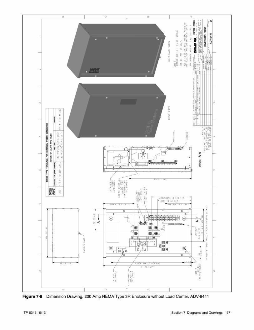
TP-6345 9/13 57Section 7 Diagrams and Drawings
Figure 7-8 Dimension Drawing, 200 Amp NEMA Type 3R Enclosure without Load Center, ADV-8441
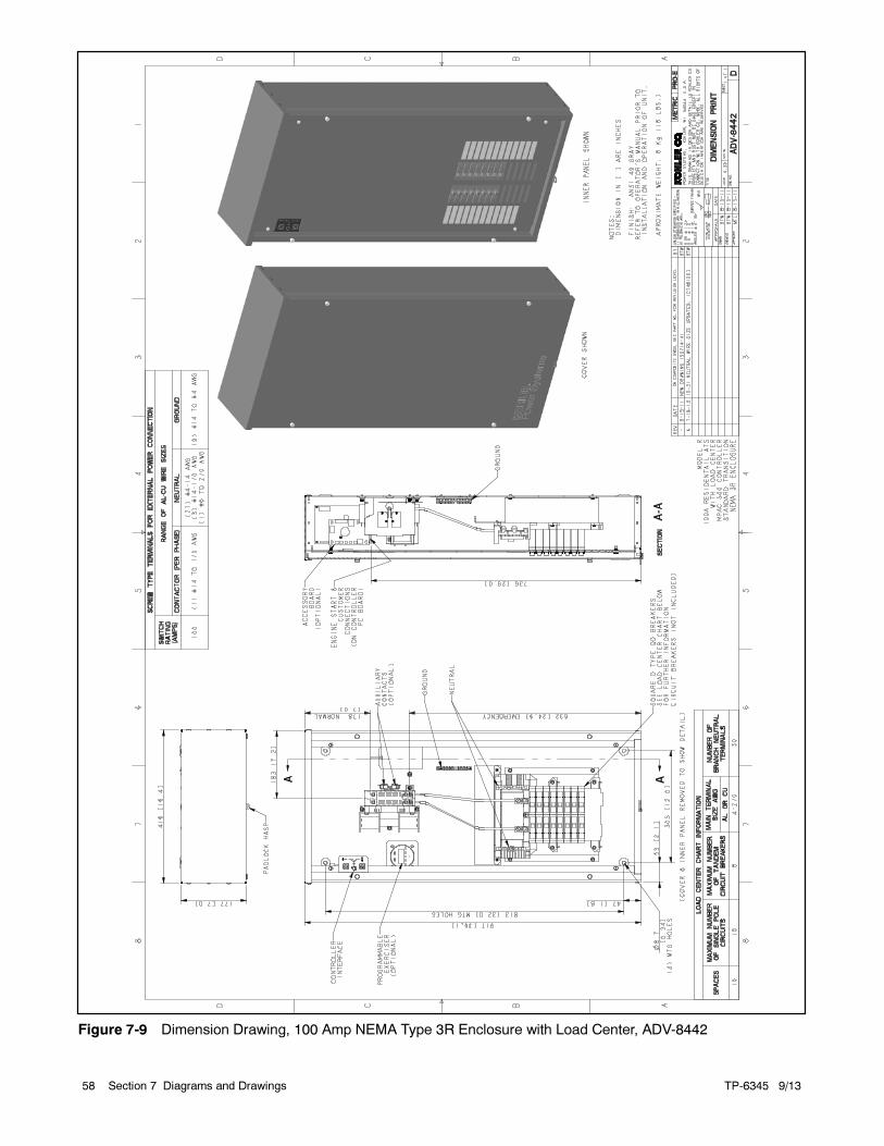
TP-6345 9/1358 Section 7 Diagrams and Drawings
Figure 7-9 Dimension Drawing, 100 Amp NEMA Type 3R Enclosure with Load Center, ADV-8442
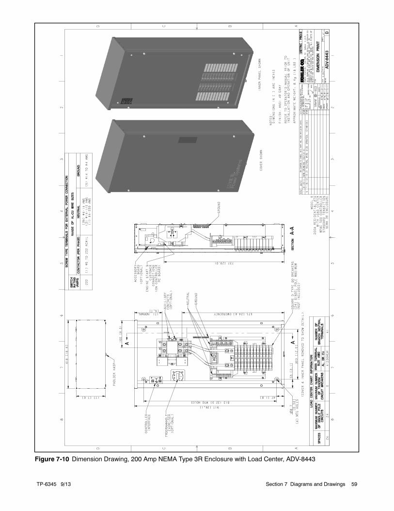
TP-6345 9/13 59Section 7 Diagrams and Drawings
Figure 7-10 Dimension Drawing, 200 Amp NEMA Type 3R Enclosure with Load Center, ADV-8443
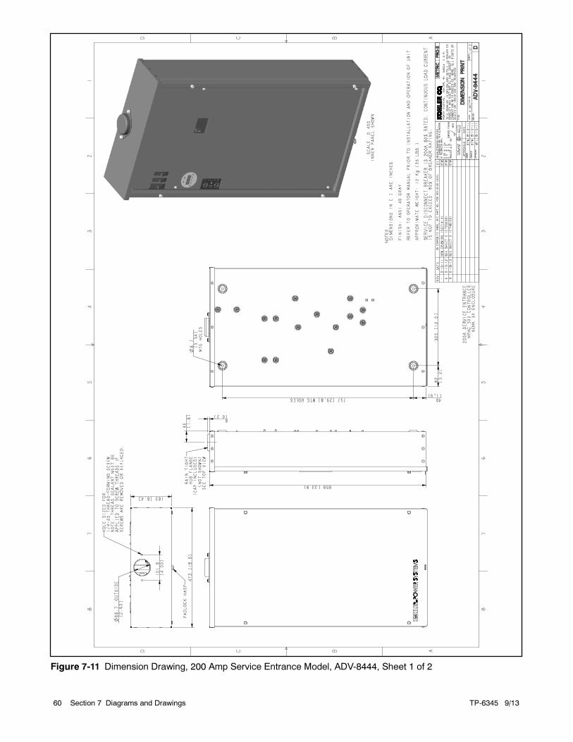
TP-6345 9/1360 Section 7 Diagrams and Drawings
Figure 7-11 Dimension Drawing, 200 Amp Service Entrance Model, ADV-8444, Sheet 1 of 2
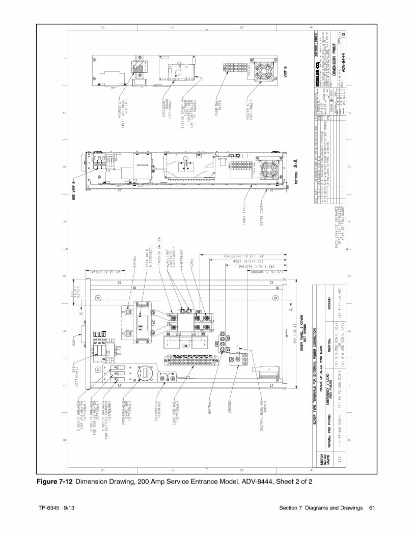
TP-6345 9/13 61Section 7 Diagrams and Drawings
Figure 7-12 Dimension Drawing, 200 Amp Service Entrance Model, ADV-8444, Sheet 2 of 2
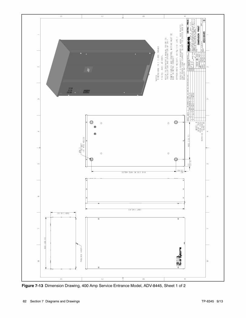
TP-6345 9/1362 Section 7 Diagrams and Drawings
Figure 7-13 Dimension Drawing, 400 Amp Service Entrance Model, ADV-8445, Sheet 1 of 2
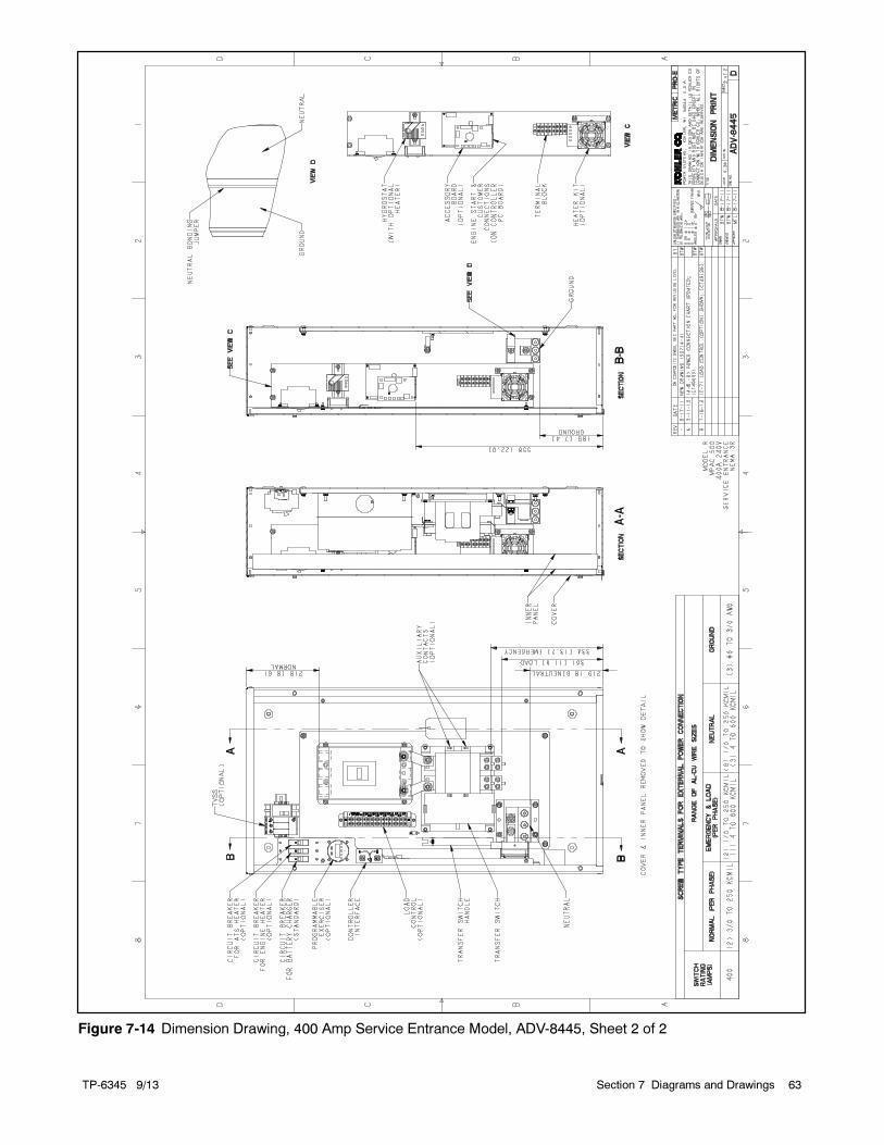
TP-6345 9/13 63Section 7 Diagrams and Drawings
Figure 7-14 Dimension Drawing, 400 Amp Service Entrance Model, ADV-8445, Sheet 2 of 2
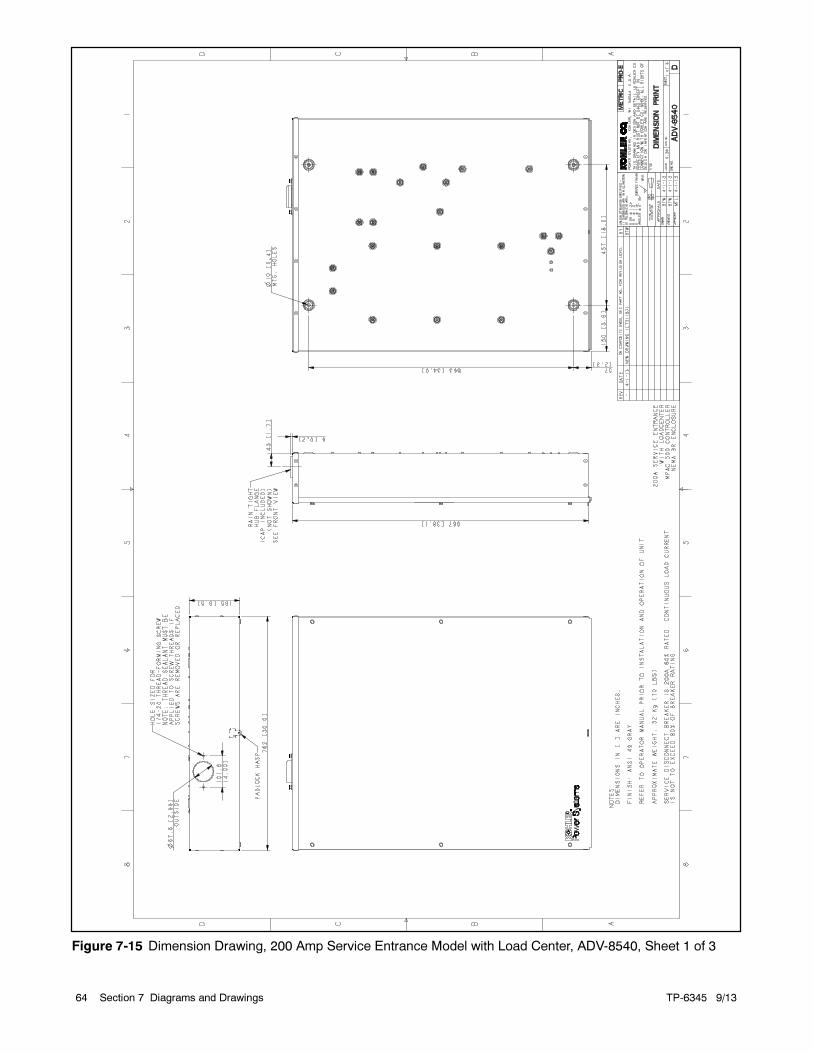
TP-6345 9/1364 Section 7 Diagrams and Drawings
Figure 7-15 Dimension Drawing, 200 Amp Service Entrance Model with Load Center, ADV-8540, Sheet 1 of 3
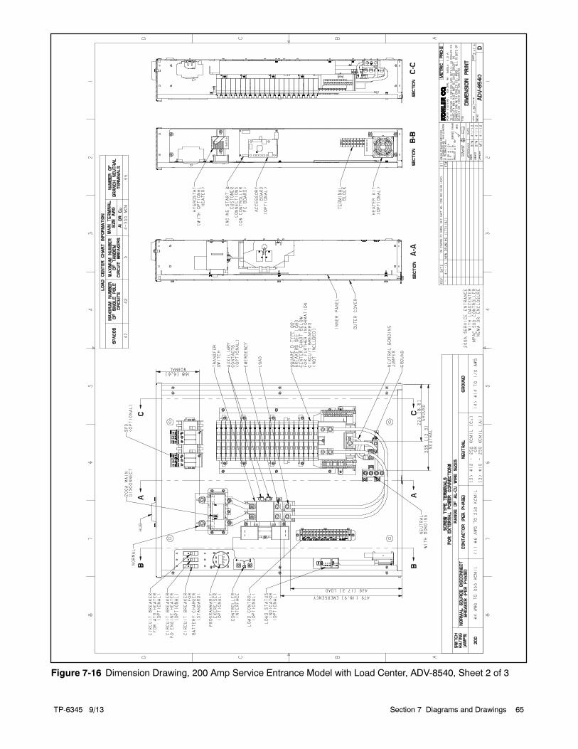
TP-6345 9/13 65Section 7 Diagrams and Drawings
Figure 7-16 Dimension Drawing, 200 Amp Service Entrance Model with Load Center, ADV-8540, Sheet 2 of 3
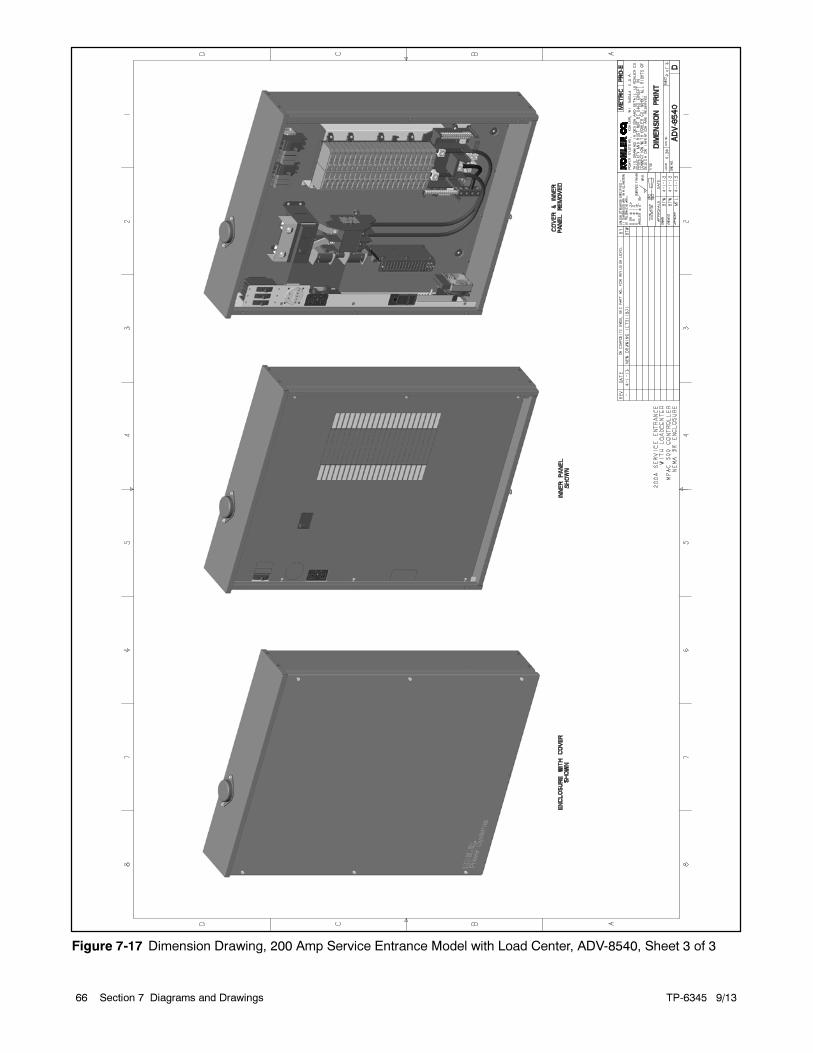
TP-6345 9/1366 Section 7 Diagrams and Drawings
Figure 7-17 Dimension Drawing, 200 Amp Service Entrance Model with Load Center, ADV-8540, Sheet 3 of 3
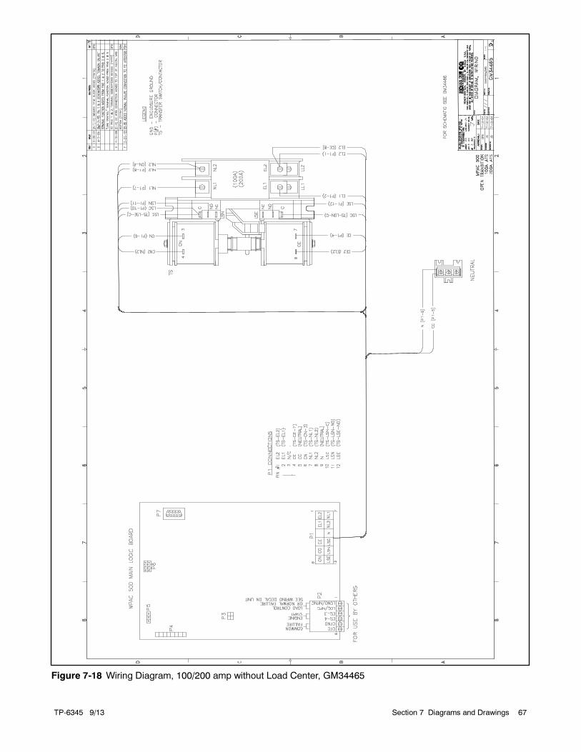
TP-6345 9/13 67Section 7 Diagrams and Drawings
Figure 7-18 Wiring Diagram, 100/200 amp without Load Center, GM34465
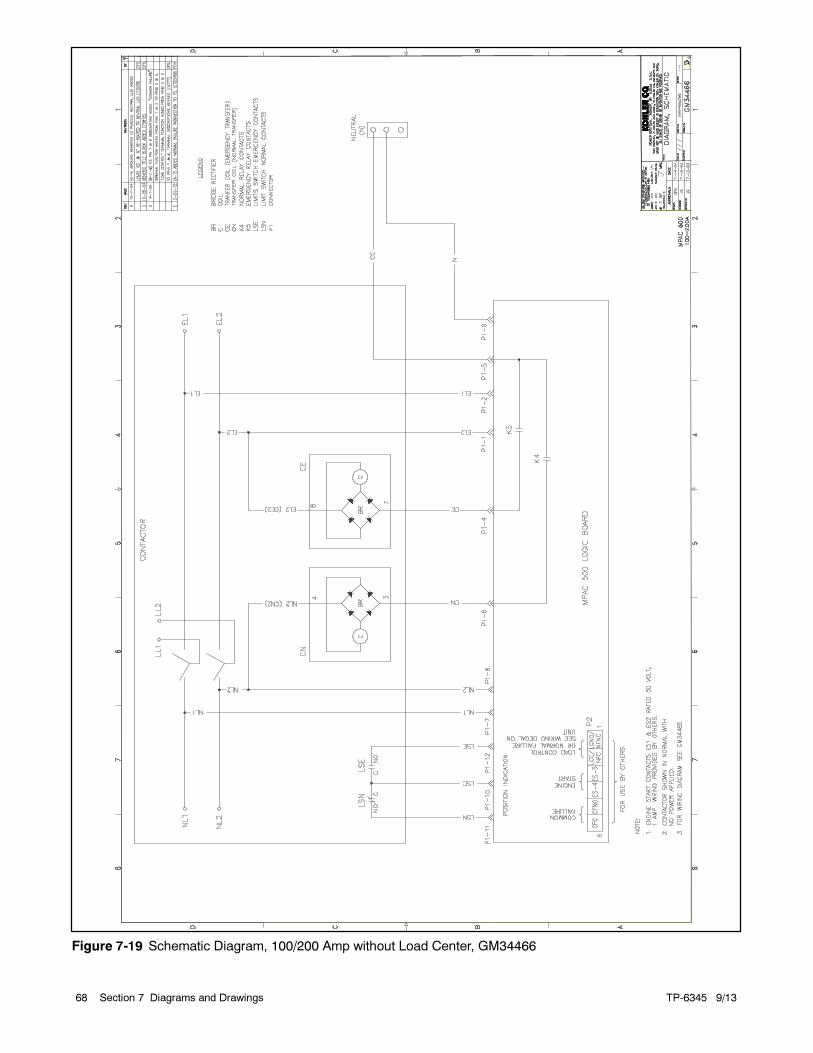
TP-6345 9/1368 Section 7 Diagrams and Drawings
Figure 7-19 Schematic Diagram, 100/200 Amp without Load Center, GM34466
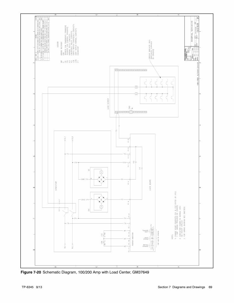
TP-6345 9/13 69Section 7 Diagrams and Drawings
Figure 7-20 Schematic Diagram, 100/200 Amp with Load Center, GM37649
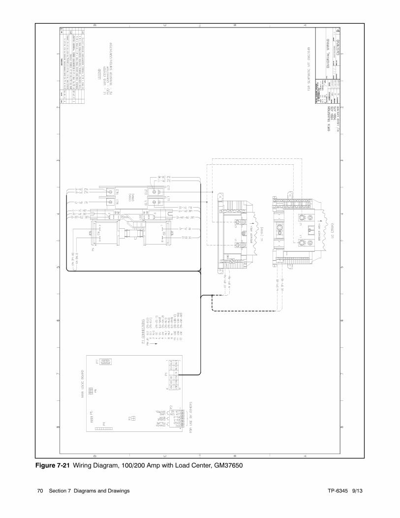
TP-6345 9/1370 Section 7 Diagrams and Drawings
Figure 7-21 Wiring Diagram, 100/200 Amp with Load Center, GM37650
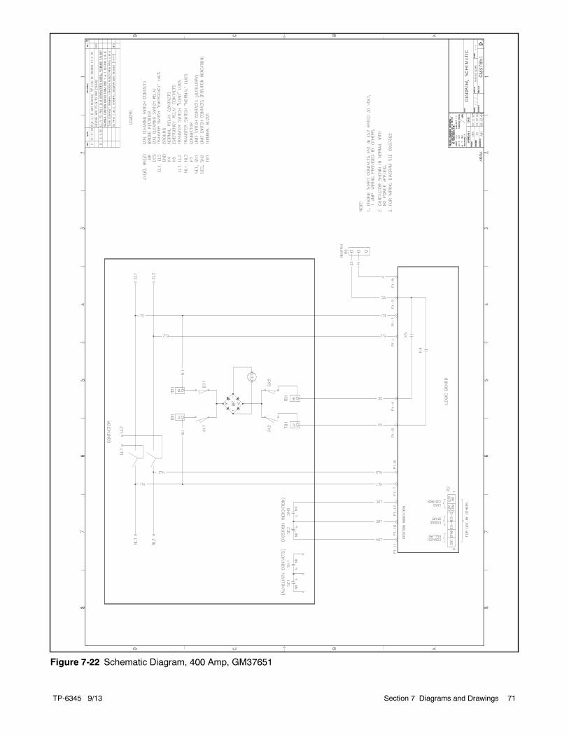
TP-6345 9/13 71Section 7 Diagrams and Drawings
Figure 7-22 Schematic Diagram, 400 Amp, GM37651
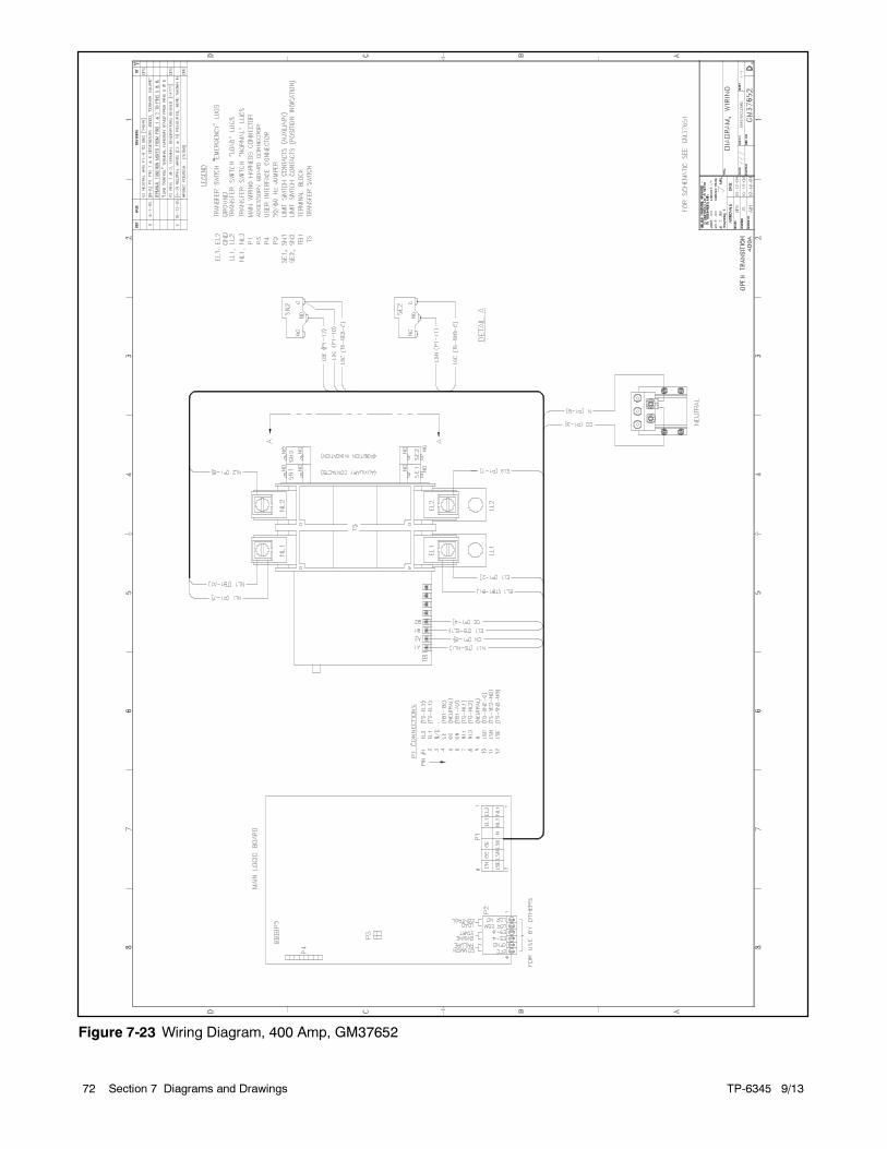
TP-6345 9/1372 Section 7 Diagrams and Drawings
Figure 7-23 Wiring Diagram, 400 Amp, GM37652
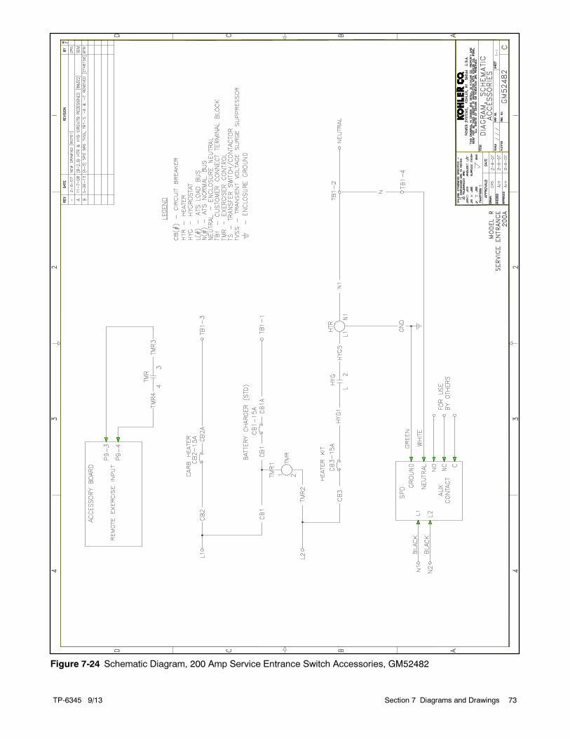
TP-6345 9/13 73Section 7 Diagrams and Drawings
Figure 7-24 Schematic Diagram, 200 Amp Service Entrance Switch Accessories, GM52482
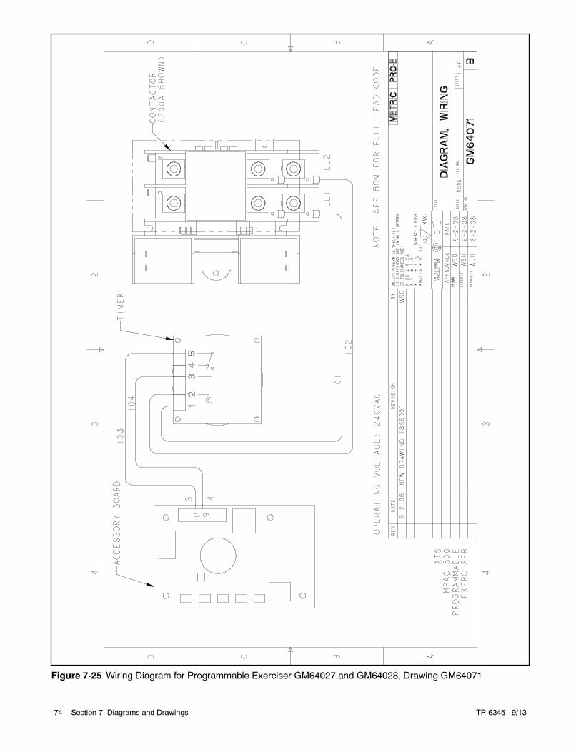
TP-6345 9/1374 Section 7 Diagrams and Drawings
Figure 7-25 Wiring Diagram for Programmable Exerciser GM64027 and GM64028, Drawing GM64071
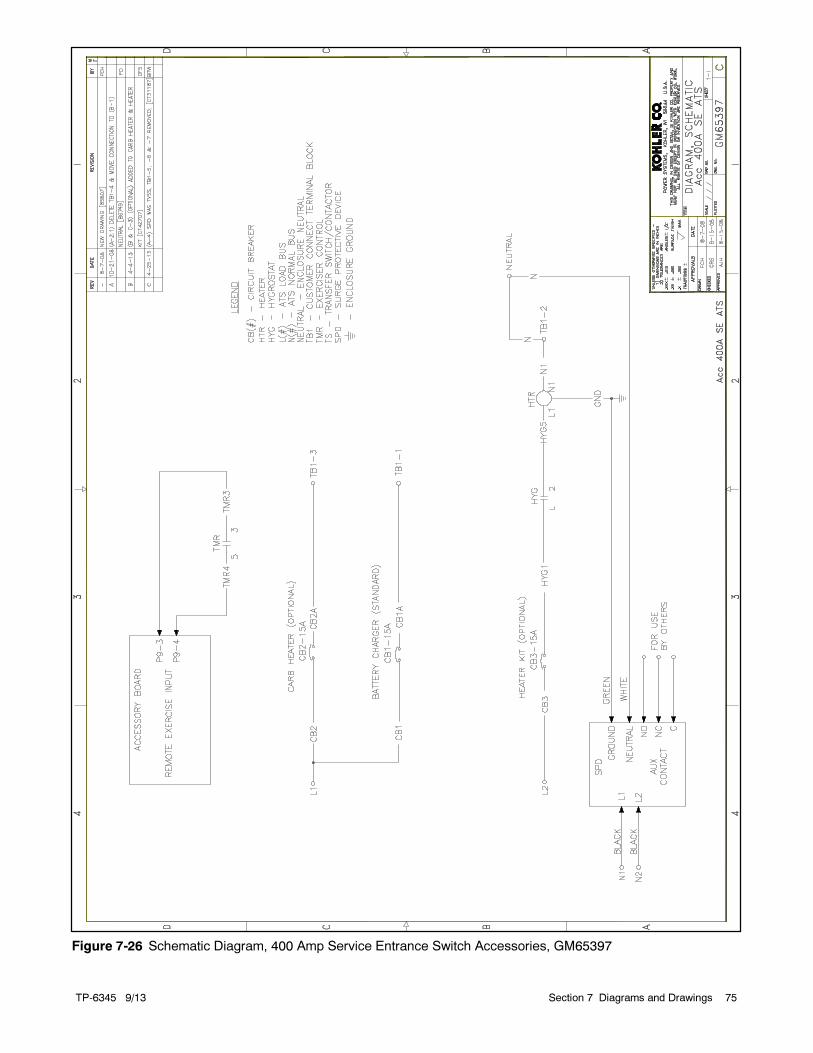
TP-6345 9/13 75Section 7 Diagrams and Drawings
Figure 7-26 Schematic Diagram, 400 Amp Service Entrance Switch Accessories, GM65397
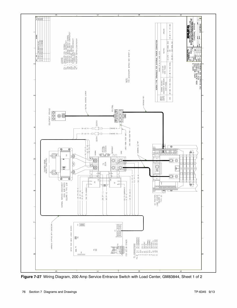
TP-6345 9/1376 Section 7 Diagrams and Drawings
Figure 7-27 Wiring Diagram, 200 Amp Service Entrance Switch with Load Center, GM83844, Sheet 1 of 2
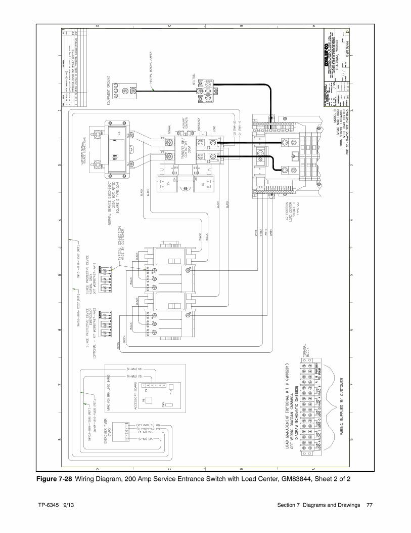
TP-6345 9/13 77Section 7 Diagrams and Drawings
Figure 7-28 Wiring Diagram, 200 Amp Service Entrance Switch with Load Center, GM83844, Sheet 2 of 2
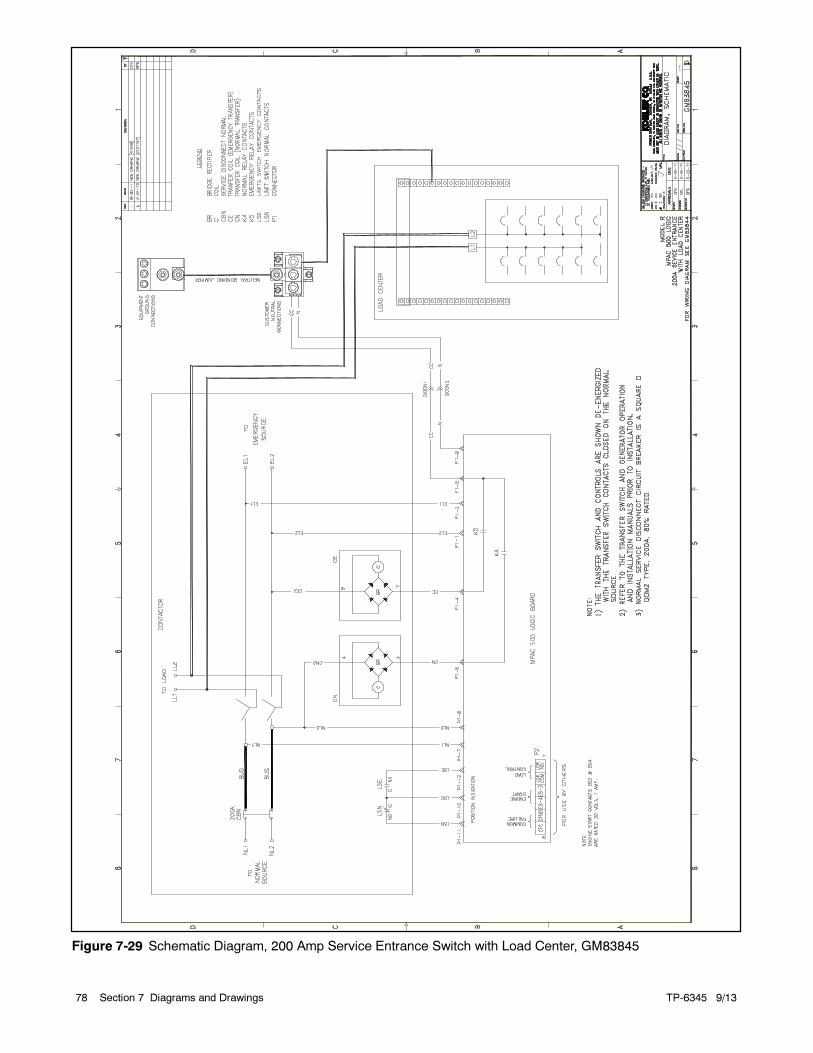
TP-6345 9/1378 Section 7 Diagrams and Drawings
Figure 7-29 Schematic Diagram, 200 Amp Service Entrance Switch with Load Center, GM83845
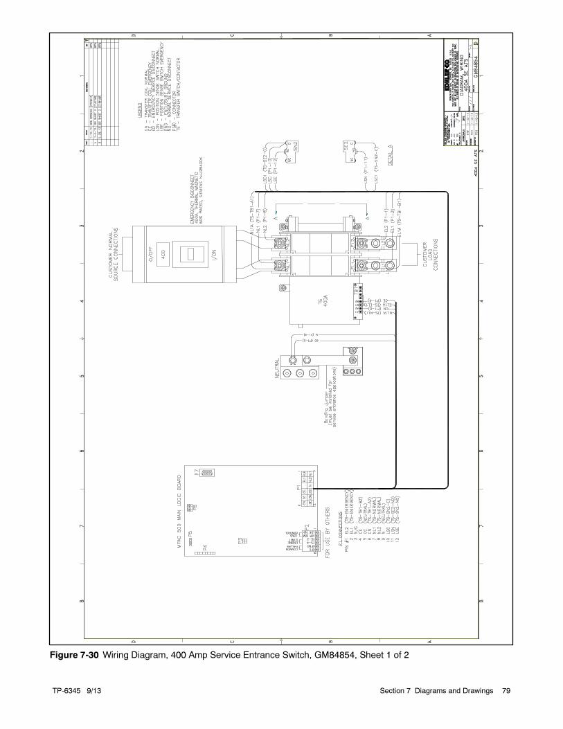
TP-6345 9/13 79Section 7 Diagrams and Drawings
Figure 7-30 Wiring Diagram, 400 Amp Service Entrance Switch, GM84854, Sheet 1 of 2
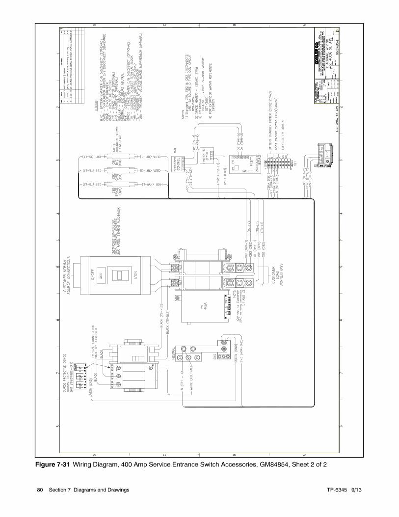
TP-6345 9/1380 Section 7 Diagrams and Drawings
Figure 7-31 Wiring Diagram, 400 Amp Service Entrance Switch Accessories, GM84854, Sheet 2 of 2
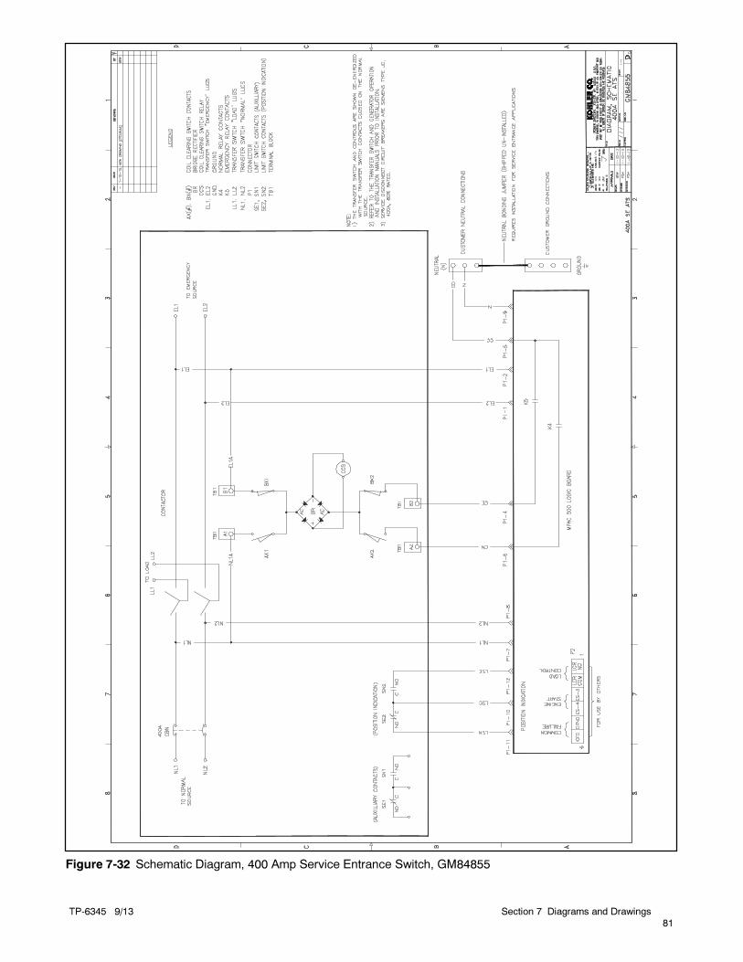
TP-6345 9/13
81
Section 7 Diagrams and Drawings
Figure 7-32 Schematic Diagram, 400 Amp Service Entrance Switch, GM84855
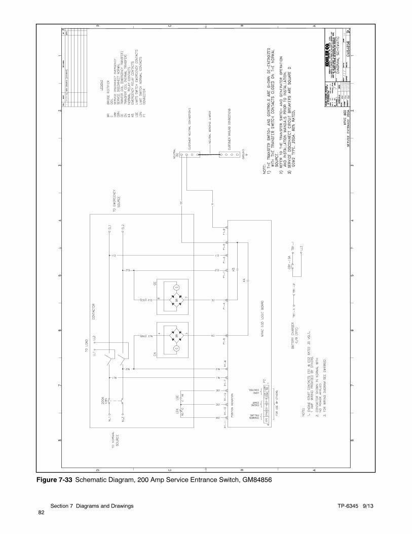
TP-6345 9/13
82
Section 7 Diagrams and Drawings
Figure 7-33 Schematic Diagram, 200 Amp Service Entrance Switch, GM84856
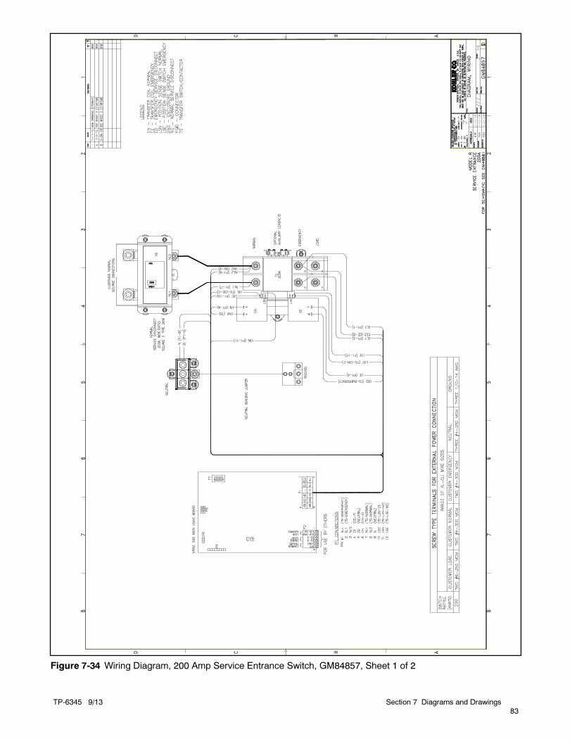
TP-6345 9/13
83
Section 7 Diagrams and Drawings
Figure 7-34 Wiring Diagram, 200 Amp Service Entrance Switch, GM84857, Sheet 1 of 2
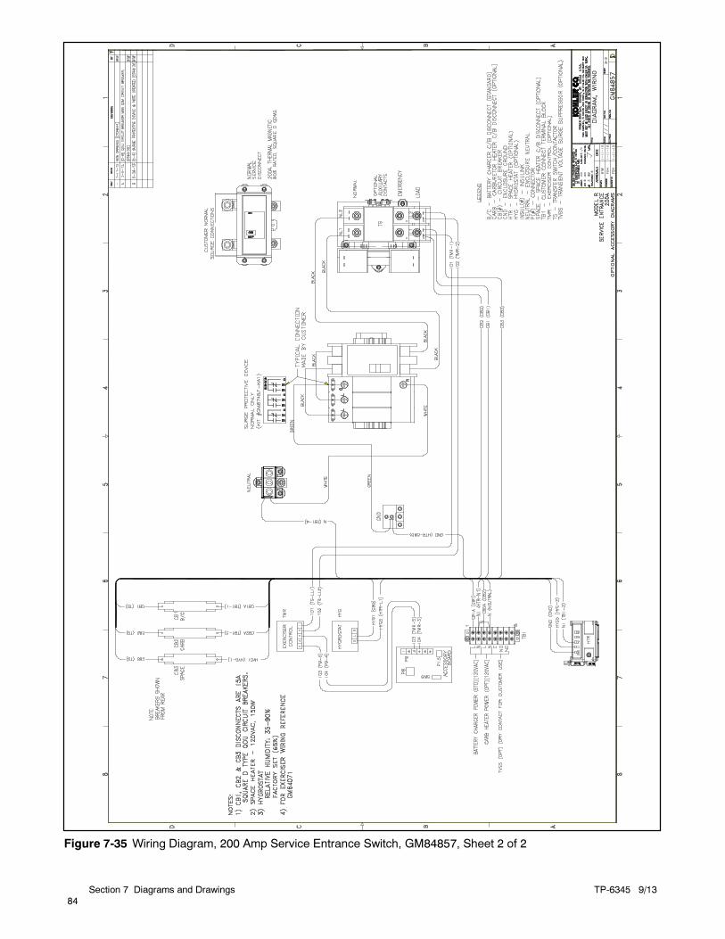
TP-6345 9/13
84
Section 7 Diagrams and Drawings
Figure 7-35 Wiring Diagram, 200 Amp Service Entrance Switch, GM84857, Sheet 2 of 2
TP-6345 9/13 Appendix 85
Appendix A Abbreviations
The following list contains abbreviations that may appear in this publication.
A, amp ampere
ABDC after bottom dead centerAC alternating current
A/D analog to digitalADC advanced digital control;
analog to digital converteradj. adjust, adjustment
ADV advertising dimensionaldrawing
Ah amp-hour
AHWT anticipatory high watertemperature
AISI American Iron and SteelInstitute
ALOP anticipatory low oil pressurealt. alternator
Al aluminum
ANSI American National StandardsInstitute (formerly AmericanStandards Association, ASA)
AO anticipatory only
APDC Air Pollution Control DistrictAPI American Petroleum Institute
approx. approximate, approximately
AQMD Air Quality Management DistrictAR as required, as requested
AS as supplied, as stated, assuggested
ASE American Society of EngineersASME American Society of
Mechanical Engineersassy. assembly
ASTM American Society for TestingMaterials
ATDC after top dead center
ATS automatic transfer switchauto. automatic
aux. auxiliary
avg. averageAVR automatic voltage regulator
AWG American Wire GaugeAWM appliance wiring material
bat. battery
BBDC before bottom dead centerBC battery charger, battery
chargingBCA battery charging alternator
BCI Battery Council International
BDC before dead centerBHP brake horsepower
blk. black (paint color), block(engine)
blk. htr. block heaterBMEP brake mean effective pressure
bps bits per second
br. brassBTDC before top dead center
Btu British thermal unit
Btu/min. British thermal units per minuteC Celsius, centigrade
cal. calorieCAN controller area network
CARB California Air Resources Board
CB circuit breakercc cubic centimeter
CCA cold cranking ampsccw. counterclockwise
CEC Canadian Electrical Code
cert. certificate, certification, certifiedcfh cubic feet per hour
cfm cubic feet per minute
CG center of gravityCID cubic inch displacement
CL centerlinecm centimeter
CMOS complementary metal oxidesubstrate (semiconductor)
cogen. cogeneration
com communications (port)coml commercial
Coml/Rec Commercial/Recreational
conn. connectioncont. continued
CPVC chlorinated polyvinyl chloridecrit. critical
CRT cathode ray tube
CSA Canadian StandardsAssociation
CT current transformerCu copper
cUL Canadian Underwriter’sLaboratories
CUL Canadian Underwriter’sLaboratories
cu. in. cubic inch
cw. clockwiseCWC city water-cooled
cyl. cylinderD/A digital to analog
DAC digital to analog converter
dB decibeldB(A) decibel (A weighted)
DC direct current
DCR direct current resistancedeg., ° degree
dept. departmentDFMEA Design Failure Mode and
Effects Analysisdia. diameter
DI/EO dual inlet/end outlet
DIN Deutsches Institut fur Normunge. V. (also Deutsche IndustrieNormenausschuss)
DIP dual inline package
DPDT double-pole, double-throwDPST double-pole, single-throw
DS disconnect switch
DVR digital voltage regulatorE, emer. emergency (power source)
ECM electronic control module,engine control module
EDI electronic data interchangeEFR emergency frequency relay
e.g. for example (exempli gratia)
EG electronic governorEGSA Electrical Generating Systems
AssociationEIA Electronic Industries
AssociationEI/EO end inlet/end outlet
EMI electromagnetic interference
emiss. emissioneng. engine
EPA Environmental ProtectionAgency
EPS emergency power systemER emergency relay
ES engineering special,engineered special
ESD electrostatic discharge
est. estimated
E-Stop emergency stopetc. et cetera (and so forth)
exh. exhaustext. external
F Fahrenheit, female
fglass. fiberglassFHM flat head machine (screw)
fl. oz. fluid ounceflex. flexible
freq. frequency
FS full scaleft. foot, feet
ft. lb. foot pounds (torque)
ft./min. feet per minuteftp file transfer protocol
g gramga. gauge (meters, wire size)
gal. gallon
gen. generatorgenset generator set
GFI ground fault interrupter
GND, groundgov. governor
gph gallons per hourgpm gallons per minute
gr. grade, gross
GRD equipment groundgr. wt. gross weight
H x W x D height by width by depth
HC hex capHCHT high cylinder head temperature
HD heavy dutyHET high exhaust temp., high
engine temp.hex hexagon
Hg mercury (element)
HH hex headHHC hex head cap
HP horsepower
hr. hourHS heat shrink
hsg. housingHVAC heating, ventilation, and air
conditioningHWT high water temperature
Hz hertz (cycles per second)
IC integrated circuitID inside diameter, identification
IEC International ElectrotechnicalCommission
IEEE Institute of Electrical andElectronics Engineers
IMS improved motor starting
in. inchin. H2O inches of water
in. Hg inches of mercuryin. lb. inch pounds
Inc. incorporated
ind. industrialint. internal
int./ext. internal/externalI/O input/output
IP iron pipe
ISO International Organization forStandardization
J jouleJIS Japanese Industry Standard

TP-6345 9/1386 Appendix
k kilo (1000)
K kelvinkA kiloampere
KB kilobyte (210 bytes)KBus Kohler communication protocol
kg kilogram
kg/cm2 kilograms per squarecentimeter
kgm kilogram-meterkg/m3 kilograms per cubic meter
kHz kilohertz
kJ kilojoulekm kilometer
kOhm, kΩ kilo-ohmkPa kilopascal
kph kilometers per hour
kV kilovoltkVA kilovolt ampere
kVAR kilovolt ampere reactivekW kilowatt
kWh kilowatt-hour
kWm kilowatt mechanicalkWth kilowatt-thermal
L liter
LAN local area networkL x W x H length by width by height
lb. pound, poundslbm/ft3 pounds mass per cubic feet
LCB line circuit breaker
LCD liquid crystal displayld. shd. load shed
LED light emitting diodeLph liters per hour
Lpm liters per minute
LOP low oil pressureLP liquefied petroleum
LPG liquefied petroleum gas
LS left sideLwa sound power level, A weighted
LWL low water levelLWT low water temperature
m meter, milli (1/1000)
M mega (106 when used with SIunits), male
m3 cubic meterm3/hr. cubic meters per hour
m3/min. cubic meters per minute
mA milliampereman. manual
max. maximumMB megabyte (220 bytes)
MCCB molded-case circuit breaker
MCM one thousand circular milsmeggar megohmmeter
MHz megahertz
mi. milemil one one-thousandth of an inch
min. minimum, minutemisc. miscellaneous
MJ megajoule
mJ millijoulemm millimeter
mOhm,mΩmilliohmMOhm, MΩmegohm
MOV metal oxide varistor
MPa megapascalmpg miles per gallon
mph miles per hour
MS military standardms millisecond
m/sec. meters per secondMTBF mean time between failure
MTBO mean time between overhauls
mtg. mountingMTU Motoren-und Turbinen-Union
MW megawattmW milliwatt
μF microfarad
N, norm. normal (power source)NA not available, not applicable
nat. gas natural gasNBS National Bureau of Standards
NC normally closed
NEC National Electrical CodeNEMA National Electrical
Manufacturers AssociationNFPA National Fire Protection
AssociationNm newton meter
NO normally open
no., nos. number, numbersNPS National Pipe, Straight
NPSC National Pipe, Straight-coupling
NPT National Standard taper pipethread per general use
NPTF National Pipe, Taper-FineNR not required, normal relay
ns nanosecondOC overcrank
OD outside diameter
OEM original equipmentmanufacturer
OF overfrequencyopt. option, optional
OS oversize, overspeed
OSHA Occupational Safety and HealthAdministration
OV overvoltageoz. ounce
p., pp. page, pagesPC personal computer
PCB printed circuit board
pF picofaradPF power factor
ph., ∅ phase
PHC Phillips head Crimptite(screw)
PHH Phillips hex head (screw)
PHM pan head machine (screw)
PLC programmable logic controlPMG permanent magnet generator
pot potentiometer, potentialppm parts per million
PROM programmable read-onlymemory
psi pounds per square inch
psig pounds per square inch gaugept. pint
PTC positive temperature coefficient
PTO power takeoffPVC polyvinyl chloride
qt. quart, quartsqty. quantity
R replacement (emergency)power source
rad. radiator, radius
RAM random access memoryRDO relay driver output
ref. reference
rem. remoteRes/Coml Residential/Commercial
RFI radio frequency interferenceRH round head
RHM round head machine (screw)
rly. relay
rms root mean square
rnd. roundROM read only memory
rot. rotate, rotatingrpm revolutions per minute
RS right side
RTU remote terminal unitRTV room temperature vulcanization
RW read/writeSAE Society of Automotive
Engineers
scfm standard cubic feet per minuteSCR silicon controlled rectifier
s, sec. secondSI Systeme international d’unites,
International System of UnitsSI/EO side in/end out
sil. silencer
SN serial numberSNMP simple network management
protocolSPDT single-pole, double-throw
SPST single-pole, single-throw
spec specificationspecs specification(s)
sq. squaresq. cm square centimeter
sq. in. square inch
SS stainless steelstd. standard
stl. steeltach. tachometer
TD time delay
TDC top dead centerTDEC time delay engine cooldown
TDEN time delay emergency tonormal
TDES time delay engine start
TDNE time delay normal toemergency
TDOE time delay off to emergencyTDON time delay off to normal
temp. temperatureterm. terminal
THD total harmonic distortion
TIF telephone influence factorTIR total indicator reading
tol. tolerance
turbo. turbochargertyp. typical (same in multiple
locations)UF underfrequency
UHF ultrahigh frequencyUL Underwriter’s Laboratories, Inc.
UNC unified coarse thread (was NC)
UNF unified fine thread (was NF)univ. universal
US undersize, underspeed
UV ultraviolet, undervoltageV volt
VAC volts alternating currentVAR voltampere reactive
VDC volts direct current
VFD vacuum fluorescent displayVGA video graphics adapter
VHF very high frequencyW watt
WCR withstand and closing rating
w/ withw/o without
wt. weight
xfmr transformer


KOHLER CO. Kohler, Wisconsin 53044Phone 920-457-4441, Fax 920-459-1646For the nearest sales/service outlet in theUS and Canada, phone 1-800-544-2444KOHLERPower.com
Kohler Power SystemsAsia Pacific Headquarters7 Jurong Pier RoadSingapore 619159Phone (65) 6264-6422, Fax (65) 6264-6455 2004, 2005, 2007, 2008, 2011, 2012, 2013 by Kohler Co. All rights reserved.
TP-6345 9/13j