Embed Size (px)
Citation preview

LENS
FD32x12.5SR4A-CV1
BB00036335-200 LC235A-CV1 2803
Operation manual
FOR YOUR SAFETY
i
This section explains important notices to use this product safely. Read the information carefully before using, and
follow the instructions.
The symbols WARNING and CAUTION indicate:
△WARNING
Do not moisten inside of the appliances. It may cause fire or electric shock.If the incident occurs, shut off the power supplied to the lens immediately. Do not look at any sorts of strong illuminant such as the sun through the lens. Eyes could be harmed. Be sure to attach all the parts securely. Dropping any parts from a height may cause severe accidents. When using a heavy camera, use the tripod mounts of both the camera and the lens to fix them securely. If using the tripod mount on the lens only, the lens may be damaged due to the weight of the camera, or the camera may become disconnected from the mount and fall down, causing a serious accident.
△WARNING Indicates the possibility of causing death or serious injury when misused.
△CAUTION Indicates the possibility of causing injury or substantial damage when misused.
Indicates what the user “should not do.”
△CAUTION
Do not leave or store the lens under direct sunshine. The lens may condense light on a near-by object, and cause a fire.Do not turn the lens toward the sun. The sunlight may be concentrated on the inside the lens causing damage to the parts.Before supplying the power to the lens, make sure all the parts are connected correctly.Take care when carrying the lens. Dropping the lens while carrying may cause injury.Make sure the power supplied to the lens is of the rated input voltage; otherwise, a fire, electrical shock, or breakage of the product may occur. In order to install or release the lens cable, be sure to hold the joint part. Do not damage the cable by gripping. It may cause fire or electric shock.If any sort of incidents such as unusual smoke, noise, smell or obstacles are found, shut off the power supplied to the lens and pull out the lens cable immediately. Please notify the sales agent from which you purchased the product.Do not modify the product: it may impair the functions of the product or cause electric shock.
FOR YOUR SAFETY
△ △
◆
◆◆◆
◆
◆
◆◆◆
◆
◆
◆

FOR YOUR SAFETY
ii
NOTICES
Do not use this product for purposes not mentioned in this manual. Lens and accessories are extremely precise instruments. Avoid strong impact.This lens is designed for indoor use. When using the lens outdoors, always take proper measures including the use of a protective cover.There may be a case that the glasses of the lens mist when the lens is carried from a cool place to a place of high temperature and high humidity. To avoid a mist on the glasses, before moving the lens, let the lens adjust to the ambient temperature of the place where the lens will be used.Put the cap on the lens when the camera is not used for a long time.A special anti-reflection coating is applied to this lens. The coating may make the lens surface appear uneven, but this does not affect the lens performance.
◆◆◆
◆
◆◆
This device complies with part 15 of the FCC Rules. Operation is subject to the following two conditions: (1) This device may not cause harmful interference, and (2) this device must accept any interference received, including interference that may cause undesired operation.
Note: This equipment has been tested and found to comply with the limits for a Class B digital device, pursuant to part 15 of the FCC Rules. These limits are designed to provide reasonable protection against harmful interference in a residential installation. This equipment generates, uses and can radiate radio frequency energy and, if not installed and used in accordance with the instructions, may cause harmful interference to radio communications. However, there is no guarantee that interference will not occur in a particular installation. If this equipment does cause harmful interference to radio or television reception, which can be determined by turning the equipment off and on, the user is encouraged to try to correct the interference by one or more of the following measures: ・ Reorient or relocate the receiving antenna. ・ Increase the separation between the equipment and receiver. ・ Connect the equipment into an outlet on a circuit different from that to which the receiver is
connected. ・ Consult the dealer or an experienced radio/TV technician for help.
CAUTION : Changes or modifications not expressly approved by the party responsible for compliance could void the user’s authority to operate the equipment.
FCC REGURATIONS
In the European Union, Norway, Iceland and Liechtenstein: This symbol on the product, or in the manual, and/or on its packaging indicates that this product shall not be treated as household waste. Instead it should be taken to an applicable collection point for the recycling of electrical and electronic equipment. By ensuring this product is disposed of correctly, you will help prevent potential negative consequences to the environment and human health, which could otherwise be caused by inappropriate waste handling of this product.
Disposal of Electrical and Electronic Equipment in Private Households
Canadian Radio Interference Regulation CAN ICES 3(B) / NMB-3(B)
CAUTION : This Class B digital apparatus complies with Canadian ICES-003.
- 1 -
CONTENTS
■ GENERAL DESCRIPTION···········································································································································2
■
■ SPECIFICATIONS··························································································································································4
◇1 OPTICAL AND MECHANICAL····························································································································4
◇2 ELECTRICAL······························································································································································5
■ INSTALLATION OF CAMERA···································································································································6
■ FIXING OF LENS····························································································································································7
■ WIRING DIAGRAM ·························································································································································8
■ SELECTION OF CONTROL MODE ························································································································9
■ ANALOG CONTROL MODE SETTING················································································································10
■ SERIAL COMMUNICATION CONTROL MODE SETTING···········································································11
■ IRIS CONTROL MODE SELECTION ····················································································································12
■ CONNECTION OF CABLE ·······································································································································13
■ OPERATION OF LENS ··············································································································································14
■ ADJUSTMENT OF FLANGE FOCAL LENGTH································································································15
■ VIDEO IRIS ADJUSTMENT······································································································································17
■ MAINTENANCE·····························································································································································18
◇1 DAILY MAINTENANCE ········································································································································18
◇2 ELIMINATION OF WATER ··································································································································18
◇3 INSPECTION····························································································································································18
■ WHEN A FAILURE IS SUSPECTED······················································································································19
■ OUTLINE DRAWING····················································································································································20
LIST OF COMPONENTS·············································································································································3
- 2 -
G E N E R A L D E S C R I P T I O N
FUJINON CCTV Lens of FD32×12.5 is a high performance zoom lens which has been developed for 1/1.8" format day/night cameras. The main features are as follows:
・ Full HD supported (when using a 1/1.8” format camera)
Shooting with the high resolution of Full HD is possible across the entire zoom range.
・ 1/1.8” format high-sensitivity sensor supported
・
・
Focal lengths ranging from 12.5 mm to 400 mm are covered using this high-magnification lens with a 32x zoom ratio.
・
・
・Stability during installation has been improved by enlarging the seating surface for mounting (*2) and by providing eight threaded holes for attachment.
*1 Distance from the lens mounting reference surface to the image surface.
*2
A 1/1.8” format high-sensitivity sensor is supported. The lens can be attached to cameras with image sizes ranging from 1/1.8” to 1/3” for use. However, in order to optimise the performance of the lens, use with a 1/1.8” format camera is recommended.
Flange focal length adjustment functionSince one of the requirements with Full HD shooting is a focusing performance that is very precise, a flange focal length adjustment function has been provided. This function enables the image-formation surface of the lens to be adjusted to the optimum position in line with the flange focal length (*1) of the camera concerned.
High magnification and long focus
Interfaces compatible with many different kinds of systems featured
Both analog control and serial communication are supported for lens control. The interface best suited to the system may be selected.In terms of serial communication control, the popular Pelco-D camera control protocol is supported in addition to our proprietary C10 protocol.
Visible light cut filter incorporated
When this lens is mounted on cameras that support near-infrared light and that are being widely used in remote monitoring, use of the visible light cut filter ensures that the images will remain clear even when visibility is compromised by the presence of mist or fog.
Improved convenience during installation
Mounting area provided on the bottom surface of the lens to enable the lens to be installed on such devices as a pan-tilt head for surveillance applications.
- 3 -
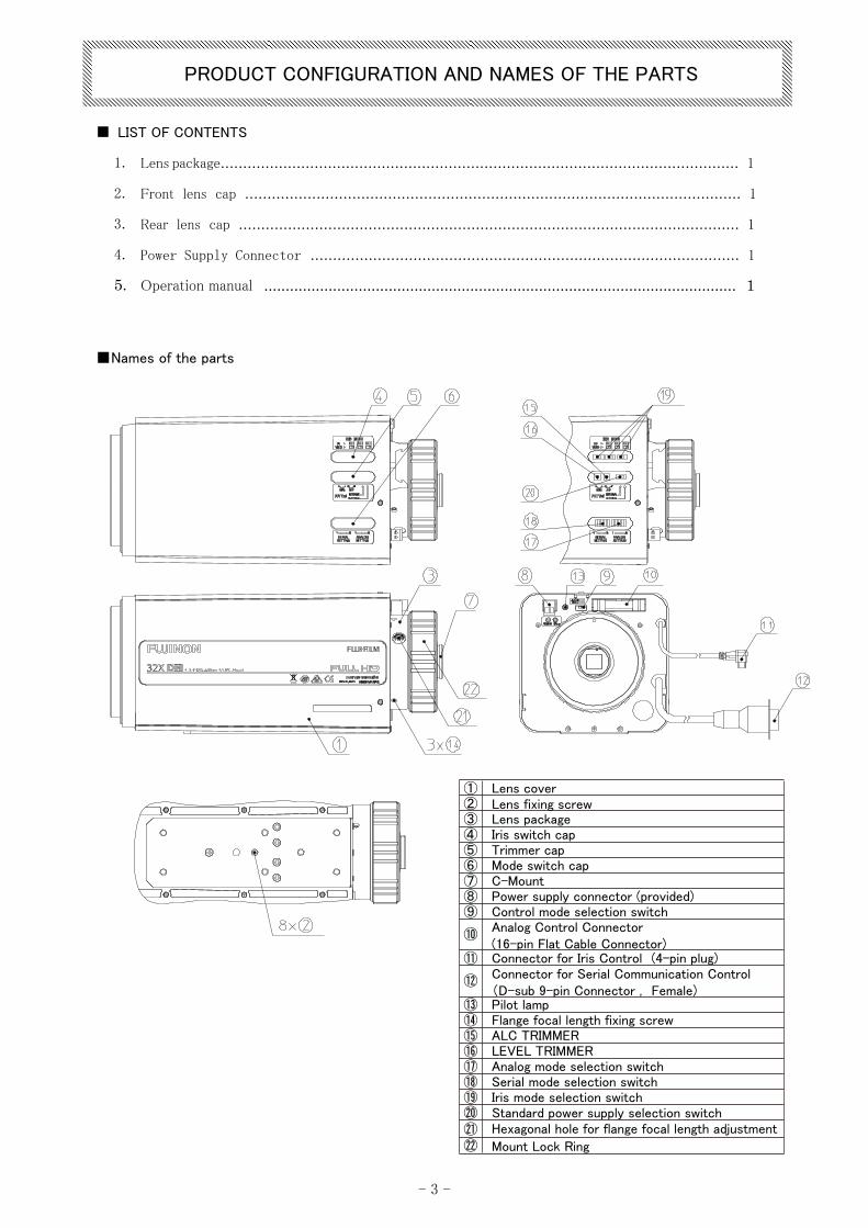
PRODUCT CONFIGURATION AND NAMES OF THE PARTS
■ LIST OF CONTENTS
1. Lens package.................................................................................................................... 1
2. Front lens cap ............................................................................................................... 1
3. Rear lens cap ................................................................................................................ 1
4. Power Supply Connector ................................................................................................ 1
5. Operation manual .............................................................................................................. 1
① Lens cover② Lens fixing screw③ Lens package④ Iris switch cap⑤ Trimmer cap⑥ Mode switch cap⑦ C-Mount⑧ Power supply connector (provided)⑨ Control mode selection switch
Analog Control Connector (16-pin Flat Cable Connector)
⑩
⑪ Connector for Iris Control (4-pin plug)Connector for Serial Communication Control (D-sub 9-pin Connector , Female)
⑫
⑬ Pilot lamp⑭ Flange focal length fixing screw⑮ ALC TRIMMER⑯ LEVEL TRIMMER⑰ Analog mode selection switch⑱ Serial mode selection switch⑲ Iris mode selection switch⑳ Standard power supply selection switch㉑ Hexagonal hole for flange focal length adjustment㉒ Mount Lock Ring
■Names of the parts
- 4 -
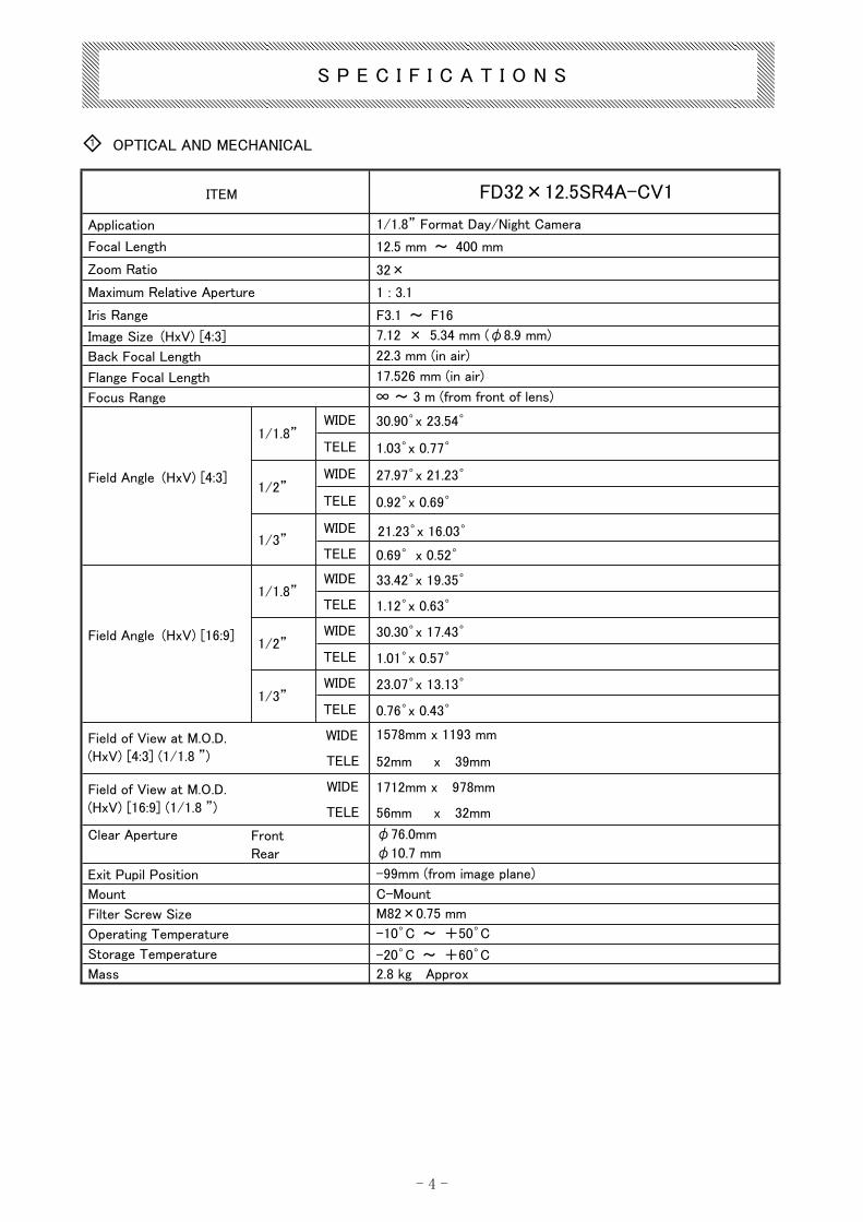
ITEM FD32×12.5SR4A-CV1
Application 1/1.8” Format Day/Night Camera
Focal Length 12.5 mm ~ 400 mm
Zoom Ratio 32×
Maximum Relative Aperture 1 : 3.1
Iris Range F3.1 ~ F16
Image Size (HxV) [4:3] 7.12 × 5.34 mm (φ8.9 mm)
Back Focal Length 22.3 mm (in air)
Flange Focal Length 17.526 mm (in air)
Focus Range ∞ ~ 3 m (from front of lens)
WIDE 30.90゜x 23.54゜ 1/1.8”
TELE 1.03゜x 0.77゜
WIDE 27.97゜x 21.23゜ 1/2”
TELE 0.92゜x 0.69゜
WIDE 21.23゜x 16.03゜
Field Angle (HxV) [4:3]
1/3” TELE 0.69゜ x 0.52゜
WIDE 33.42゜x 19.35゜ 1/1.8”
TELE 1.12゜x 0.63゜
WIDE 30.30゜x 17.43゜ 1/2”
TELE 1.01゜x 0.57゜
WIDE 23.07゜x 13.13゜
Field Angle (HxV) [16:9]
1/3” TELE 0.76゜x 0.43゜
WIDE 1578mm x 1193 mm Field of View at M.O.D.
(HxV) [4:3] (1/1.8 ”) TELE 52mm x 39mm
WIDE 1712mm x 978mm Field of View at M.O.D.
(HxV) [16:9] (1/1.8 ”) TELE 56mm x 32mm
Clear Aperture Front
Rear
φ76.0mm
φ10.7 mm
Exit Pupil Position -99mm (from image plane)
Mount C-Mount
Filter Screw Size M82×0.75 mm
Operating Temperature -10゜C ~ +50゜C
Storage Temperature -20゜C ~ +60゜C
Mass 2.8 kg Approx
S P E C I F I C A T I O N S
1◇ OPTICAL AND MECHANICAL
- 5 -
Serial Communication Control
Communication specifications
D-sub 9-pin Connector (Female)
RS-232C
Communication Protocol
Baud rate
Device address Selected from 1 to 16 (Pelco-D)
Analog Control
16-pin Flat Cable Connector
Control Voltage
(Zoom) DC 6/9/12V,±6/±9/±12V
Potentiometer reference voltage
(*) Selected using a switch
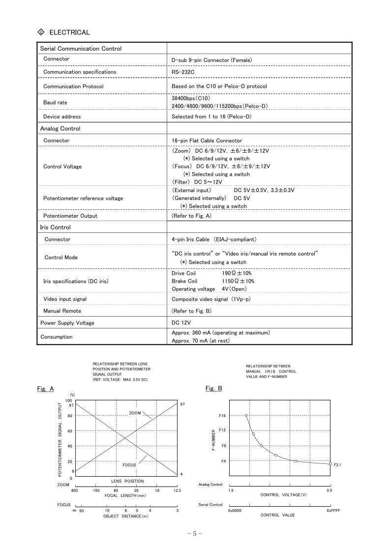
Potentiometer Output (Refer to Fig. A)
Iris Control
4-pin Iris Cable (EIAJ-compliant)
Control Mode “DC iris control” or “Video iris/manual iris remote control”
Iris specifications (DC iris)
Composite video signal (1Vp-p)
(Refer to Fig. B)
Power Supply Voltage DC 12V
Consumption Approx. 360 mA (operating at maximum)
Approx. 70 mA (at rest)
Fig. A
RELATIONSHIP BETWEEN LENS
POSITION AND POTENTIOMETER
SIGNAL OUTPUT
(REF. VOLTAGE: MAX. 5.5V DC)
RELATIONSHIP BETWEEN
MANUAL I R I S CONTROL
VALUE AND F-NUMBER
F4
F16
F-N
UM
BER
Analog Control
CONTROL VOLTAGE(V)1.5 5.5
Serial Control
CONTROL VALUE0x0000 0xFFFF
F8
F12
F3.120
40
60
80
100
0
(%)
LENS POSITION
PO
TEN
TIO
NM
ET
ER
S
IGN
AL
OU
TP
UT
ZOOM
FOCUS
FOCAL LENGTH(mm)
OBJECT DISTANCE(m)
400 12.5
∞
97
8
97
4
ZOOM
FOCUS
183060150
34561050
◇2 ELECTRICAL
Connector
Based on the C10 or Pelco-D protocol
38400bps(C10)
2400/4800/9600/115200bps(Pelco-D)
Connector
(*) Selected using a switch
(Focus) DC 6/9/12V,±6/±9/±12V
(*) Selected using a switch
(Filter) DC 5~12V
(External input)
(Generated internally)
DC 5V±0.5V,3.3±0.3V
DC 5V
Connector
(*) Selected using a switch
Drive Coil
Brake Coil
Operating voltage
1150Ω±10%
4V(Open)
190Ω±10%
Video input signal
Manual Remote
Fig. B
- 6 -
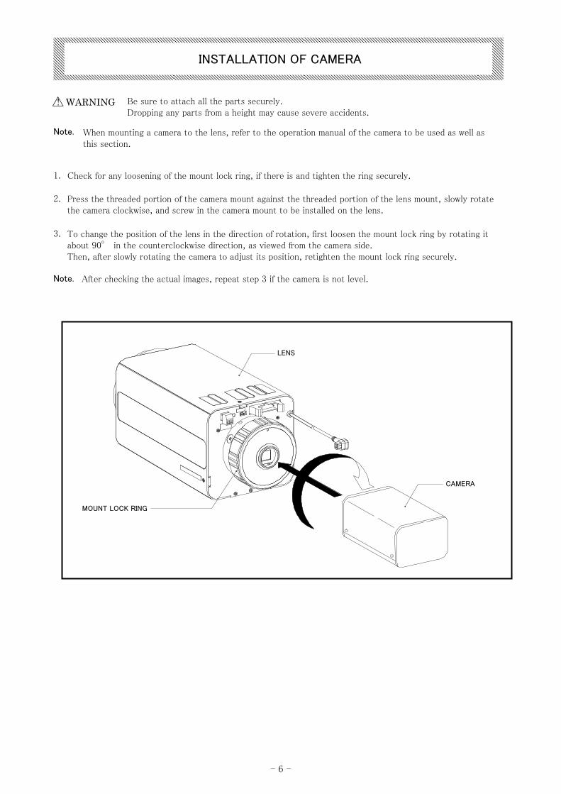
INSTALLATION OF CAMERA
! WARNING
Note.
1.
2. Press the threaded portion of the camera mount against the threaded portion of the lens mount, slowly rotatethe camera clockwise, and screw in the camera mount to be installed on the lens.
3. To change the position of the lens in the direction of rotation, first loosen the mount lock ring by rotating itabout 90° in the counterclockwise direction, as viewed from the camera side.Then, after slowly rotating the camera to adjust its position, retighten the mount lock ring securely.
After checking the actual images, repeat step 3 if the camera is not level.
△ Be sure to attach all the parts securely. Dropping any parts from a height may cause severe accidents.
When mounting a camera to the lens, refer to the operation manual of the camera to be used as well as this section.
Check for any loosening of the mount lock ring, if there is and tighten the ring securely.
Note.
LENS
CAMERA
MOUNT LOCK RING
- 7 -
FIXING OF LENS
! WARNING
Note.
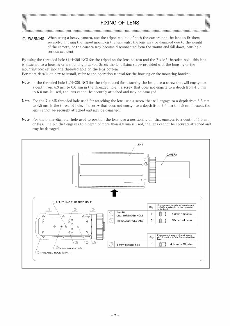
For the 7 x M5 threaded hole used for attaching the lens, use a screw that will engage to a depth from 3.5 mm to 4.5 mm in the threaded hole. If a screw that does not engage to a depth from 3.5 mm to 4.5 mm is used, the lens cannot be securely attached and may be damaged.
For the 5 mm-diameter hole used to position the lens, use a positioning pin that engages to a depth of 4.5 mm or less. If a pin that engages to a depth of more than 4.5 mm is used, the lens cannot be securely attached and may be damaged.
LENS
CAMERA
1/4-20 UNC THREADED HOLEEngagement lengths of attachment screws in relation to the threaded hole depth
Qty.
1/4-20 UNC THREADED HOLE
1 4.3mm~6.0mm
THREADED HOLE (M5) 7 3.5mm~4.5mm
Engagement length of positioning pin in relation to the 5 mm-diameter hole
Qty.
5 mm-diameter hole 4.5mm or Shorter5 mm-diameter hole
THREADED HOLE (M5)×7
△ When using a heavy camera, use the tripod mounts of both the camera and the lens to fix them securely. If using the tripod mount on the lens only, the lens may be damaged due to the weight of the camera, or the camera may become disconnected from the mount and fall down, causing a serious accident.
By using the threaded hole (1/4-20UNC) for the tripod on the lens bottom and the 7 x M5 threaded hole, this lens is attached to a housing or a mounting bracket. Screw the lens fixing screw provided with the housing or the mounting bracket into the threaded hole on the lens bottom. For more details on how to install, refer to the operation manual for the housing or the mounting bracket.
In the threaded hole (1/4-20UNC) for the tripod used for attaching the lens, use a screw that will engage to a depth from 4.3 mm to 6.0 mm in the threaded hole.If a screw that does not engage to a depth from 4.3 mm to 6.0 mm is used, the lens cannot be securely attached and may be damaged.
Note.
Note.
- 8 -
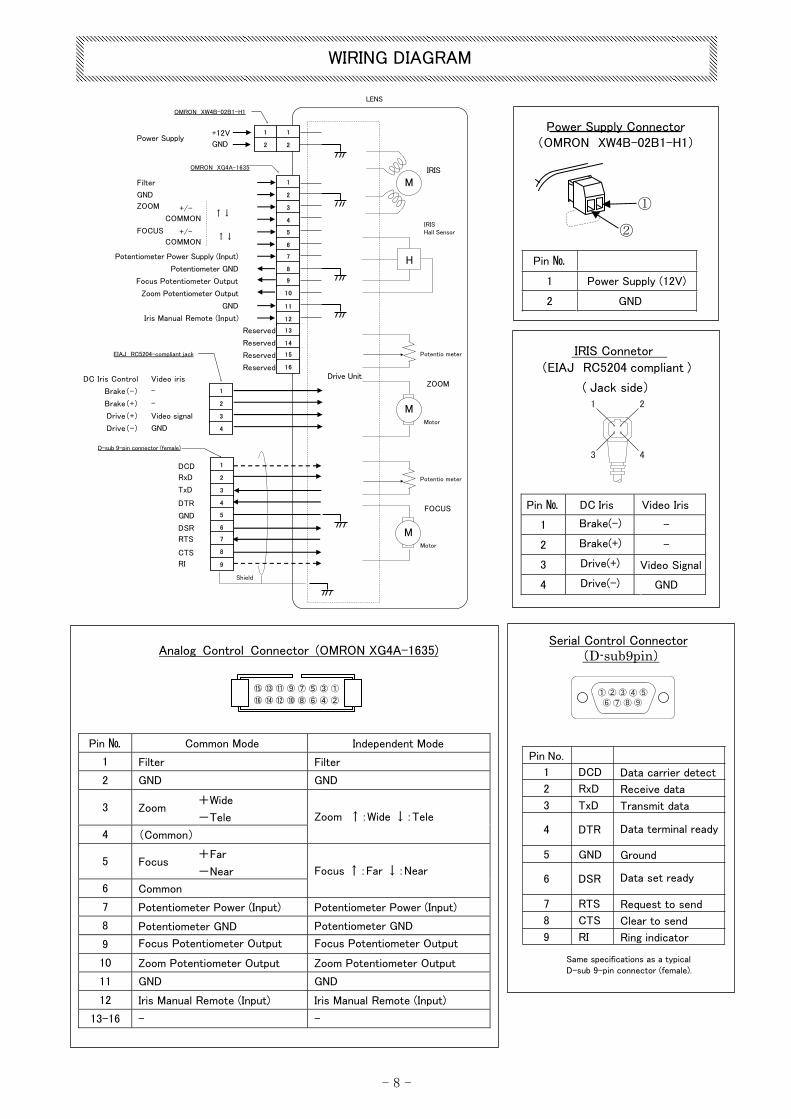
Analog Control Connector (OMRON XG4A-1635)
Pin № Common Mode Independent Mode
1 Filter Filter
2 GND GND
3 Zoom +Wide
-Tele
4 (Common)
Zoom ↑:Wide ↓:Tele
5 Focus +Far
-Near
6 Common
Focus ↑:Far ↓:Near
7 Potentiometer Power (Input) Potentiometer Power (Input)
8 Potentiometer GND Potentiometer GND
9 Focus Potentiometer Output Focus Potentiometer Output
10 Zoom Potentiometer Output Zoom Potentiometer Output
11 GND GND
12 Iris Manual Remote (Input) Iris Manual Remote (Input)
13-16 - -
IRIS Connetor
(EIAJ RC5204 compliant )
( Jack side)
Pin № DC Iris Video Iris
1 Brake(-) -
2 Brake(+) -
3 Drive(+) Video Signal
4 Drive(-) GND
Pin №
1 Power Supply (12V)
2 GND
Power Supply Connector(OMRON XW4B-02B1-H1)
①
②
Serial Control Connector(D-sub9pin)
Pin No.
1 DCD Data carrier detect
2 RxD Receive data
3 TxD Transmit data
4 DTR Data terminal ready
5 GND Ground
6 DSR Data set ready
7 RTS Request to send
8 CTS Clear to send
9 RI Ring indicator
Same specifications as a typical D-sub 9-pin connector (female).
Shield
M
M
M
LENS
H
FOCUS
ZOOM
Motor
Motor
Potentio meter
IRIS
IRIS Hall Sensor
Drive Unit
OMRON XG4A-1635
OMRON XW4B-02B1-H1
EIAJ RC5204-compliant jack
D-sub 9-pin connector (female)
1
2
1
2
1
2
3
4
5
6
7
8
9
10
11
12
13
14
15
16
Reserved
Reserved
Reserved
Reserved
1
2
3
4
1
2
3
4
5
6
7
8
9
+12V
GNDPower Supply
Filter
GND
ZOOM
FOCUS
+/-COMMON
+/-COMMON
↑↓
↑↓
DCD
RxD
TxD
DTR
GND
DSR
RTS
CTS
RI
DC Iris Control Video iris
Brake(-)
Brake(+)
Drive(+)
Drive(-)
-
-
Video signal
GND
①
②
⑮
⑯
⑬
⑭
⑪
⑫
⑨
⑩
⑦
⑧
⑤
⑥
③
④① ② ③ ④ ⑤
⑥ ⑦ ⑧ ⑨
WIRING DIAGRAM
Potentiometer Power Supply (Input)
Potentiometer GND
Focus Potentiometer Output
Zoom Potentiometer Output
GND
Iris Manual Remote (Input)
Potentio meter
- -9
SELECTION OF CONTROL MODE
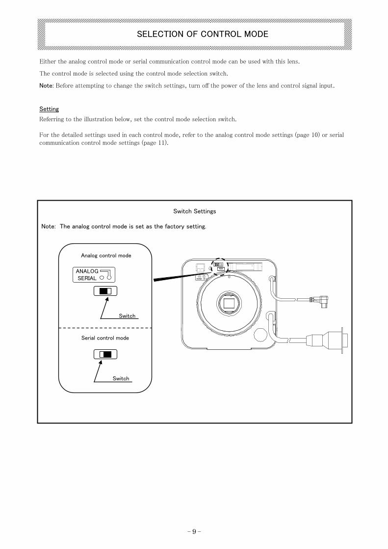
Analog control mode
Switch
Serial control mode
ANALOGSERIAL
Either the analog control mode or serial communication control mode can be used with this lens.
The control mode is selected using the control mode selection switch.
Note: Before attempting to change the switch settings, turn off the power of the lens and control signal input.
Setting
Referring to the illustration below, set the control mode selection switch.
For the detailed settings used in each control mode, refer to the analog control mode settings (page 10) or serial communication control mode settings (page 11).
Switch Settings
Note: The analog control mode is set as the factory setting.
Switch
- -10
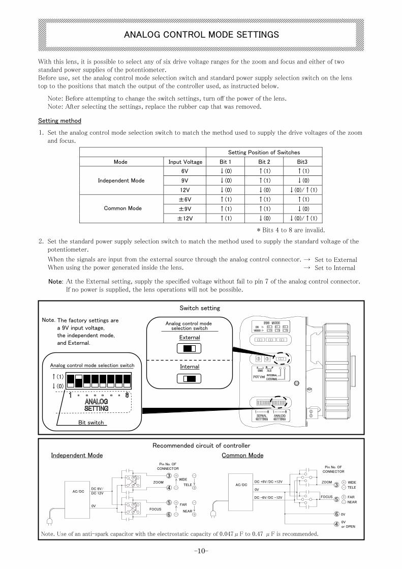
Setting Position of Switches
Mode Input Voltage Bit 1 Bit 2 Bit3
6V ↓(0) ↑(1) ↑(1)
9V ↓(0) ↑(1) ↓(0) Independent Mode
12V ↓(0) ↓(0) ↓(0)/↑(1)
±6V ↑(1) ↑(1) ↑(1)
±9V ↑(1) ↑(1) ↓(0) Common Mode
±12V ↑(1) ↓(0) ↓(0)/↑(1)
Internal
Switch setting
Analog control mode selection switch
↑(1)
↓(0)
Bit switch
Independent Mode
Note. The factory settings are a 9V input voltage, the independent mode, and External.
Recommended circuit of controller
Common Mode
Note: At the External setting, supply the specified voltage without fail to pin 7 of the analog control connector. If no power is supplied, the lens operations will not be possible.
With this lens, it is possible to select any of six drive voltage ranges for the zoom and focus and either of two standard power supplies of the potentiometer.Before use, set the analog control mode selection switch and standard power supply selection switch on the lens top to the positions that match the output of the controller used, as instructed below.
Note: Before attempting to change the switch settings, turn off the power of the lens.Note: After selecting the settings, replace the rubber cap that was removed.
Setting method
Set the analog control mode selection switch to match the method used to supply the drive voltages of the zoom and focus.
1.
* Bits 4 to 8 are invalid.
Set the standard power supply selection switch to match the method used to supply the standard voltage of the potentiometer.
2.
When the signals are input from the external source through the analog control connector.When using the power generated inside the lens.
→ Set to External→ Set to Internal
Analog control mode selection switch
External
Note. Use of an anti-spark capacitor with the electrostatic capacity of 0.047μF to 0.47 μF is recommended.
ANALOG CONTROL MODE SETTINGS
③ZOOM DC +6V/DC +12V ZOOM
AC/DC ③④
AC/DC 0V
DC -6V/DC -12V FOCUS⑤
⑤0V FAR
FOCUSNEAR
⑥ ⑥ 0V
④
Pin No. OFCONNECTOR Pin No. OF
CONNECTOR
WIDE
TELEWIDE
TELEDC 6V/DC 12V
FAR
NEAR
0Vor OPEN
- -11
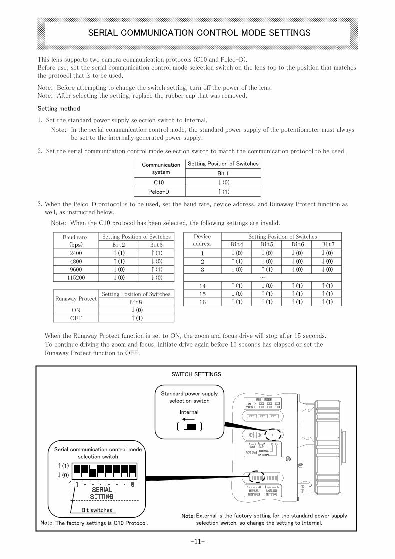
1. Set the standard power supply selection switch to Internal.
2. Set the serial communication control mode selection switch to match the communication protocol to be used.
Setting Position of Switches Communication system Bit 1
C10 ↓(0)
Pelco-D ↑(1)
3. When the Pelco-D protocol is to be used, set the baud rate, device address, and Runaway Protect function as well, as instructed below.
Note: When the C10 protocol has been selected, the following settings are invalid.
Setting Position of Switches Setting Position of SwitchesBaud rate(bps) Bit2 Bit3
Device address
2400 ↑(1) ↑(1) 1 ↓(0) ↓(0) ↓(0) ↓(0)
4800 ↑(1) ↓(0) 2 ↑(1) ↓(0) ↓(0) ↓(0)
9600 ↓(0) ↑(1) 3 ↓(0) ↑(1) ↓(0) ↓(0)
115200 ↓(0) ↓(0) ~
14 ↑(1) ↓(0) ↑(1) ↑(1)
Setting Position of Switches 15 ↓(0) ↑(1) ↑(1) ↑(1)Runaway Protect
Bit8 16 ↑(1) ↑(1) ↑(1) ↑(1)
ON ↓(0)
OFF ↑(1)
When the Runaway Protect function is set to ON, the zoom and focus drive will stop after 15 seconds.
To continue driving the zoom and focus, initiate drive again before 15 seconds has elapsed or set the
Runaway Protect function to OFF.
Internal
Standard power supply selection switch
Bit switches
Serial communication control mode selection switch
↑(1)
↓(0)
This lens supports two camera communication protocols (C10 and Pelco-D).Before use, set the serial communication control mode selection switch on the lens top to the position that matches the protocol that is to be used.
Note: Before attempting to change the switch setting, turn off the power of the lens.Note: After selecting the setting, replace the rubber cap that was removed.
Setting method
In the serial communication control mode, the standard power supply of the potentiometer must always be set to the internally generated power supply.
Note:
Bit4 Bit5 Bit6 Bit7
SWITCH SETTINGS
Note:Note. The factory settings is C10 Protocol.
External is the factory setting for the standard power supply selection switch, so change the setting to Internal.
SERIAL COMMUNICATION CONTROL MODE SETTINGS
- -12
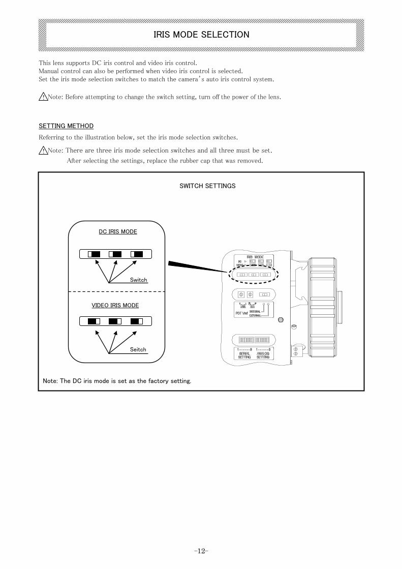
Note: Before attempting to change the switch setting, turn off the power of the lens.
Note: There are three iris mode selection switches and all three must be set.
After selecting the settings, replace the rubber cap that was removed.
!
!
DC IRIS MODE
Switch
VIDEO IRIS MODE
Seitch
IRIS MODE SELECTION
This lens supports DC iris control and video iris control.Manual control can also be performed when video iris control is selected.Set the iris mode selection switches to match the camera’s auto iris control system.
SETTING METHOD
Referring to the illustration below, set the iris mode selection switches.
SWITCH SETTINGS
Note: The DC iris mode is set as the factory setting.
- -13
CONNECTION OF CABLE
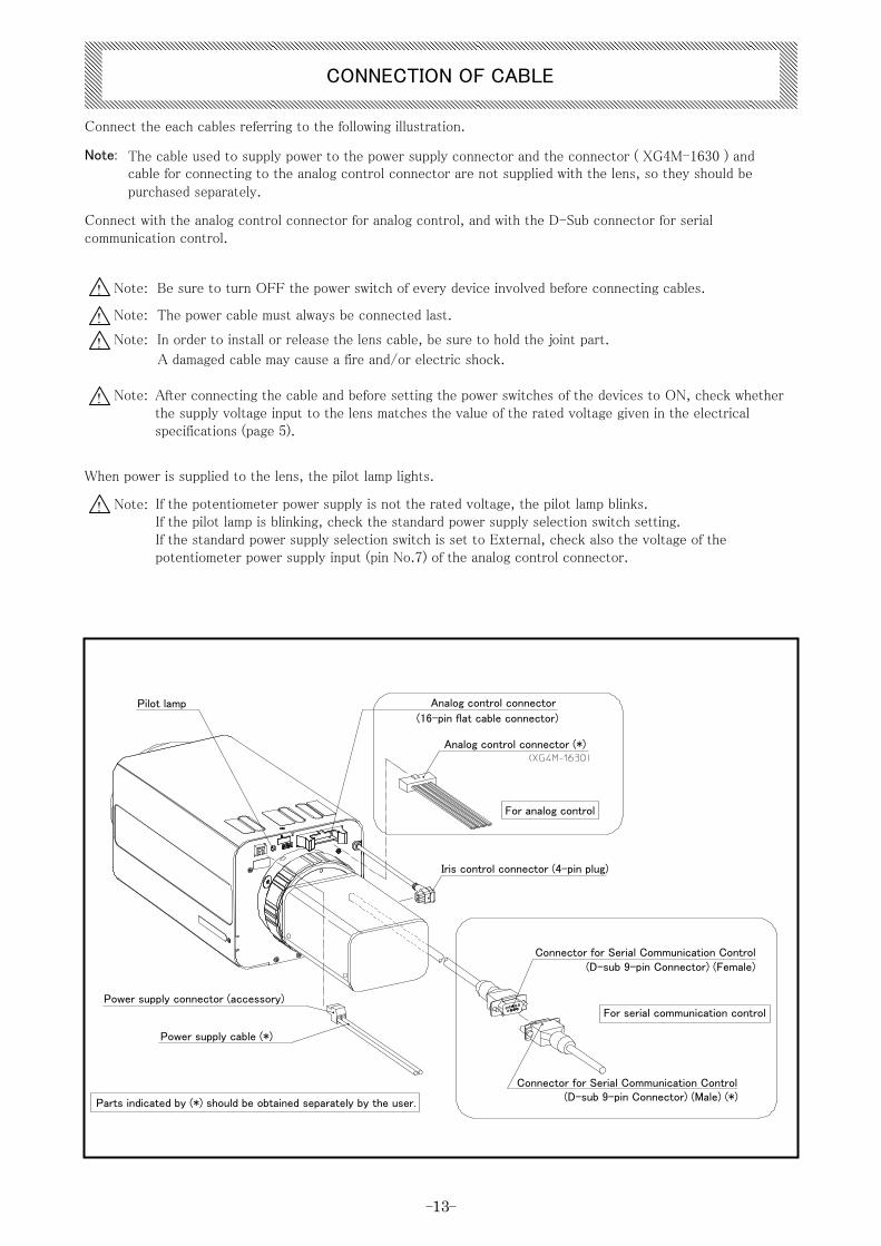
Connect the each cables referring to the following illustration.
Note:
When power is supplied to the lens, the pilot lamp lights.
!
! !
!
The cable used to supply power to the power supply connector and the connector ( XG4M-1630 ) and cable for connecting to the analog control connector are not supplied with the lens, so they should be purchased separately.
Connect with the analog control connector for analog control, and with the D-Sub connector for serial communication control.
Note: Be sure to turn OFF the power switch of every device involved before connecting cables.
Note: The power cable must always be connected last.
Note: In order to install or release the lens cable, be sure to hold the joint part.
A damaged cable may cause a fire and/or electric shock.
Note: After connecting the cable and before setting the power switches of the devices to ON, check whether the supply voltage input to the lens matches the value of the rated voltage given in the electrical specifications (page 5).
! Note: If the potentiometer power supply is not the rated voltage, the pilot lamp blinks.If the pilot lamp is blinking, check the standard power supply selection switch setting.If the standard power supply selection switch is set to External, check also the voltage of the potentiometer power supply input (pin No.7) of the analog control connector.
Pilot lamp
For analog control
Iris control connector (4-pin plug)
Connector for Serial Communication Control(D-sub 9-pin Connector) (Female)
Power supply connector (accessory)For serial communication control
Power supply cable (*)
Connector for Serial Communication Control(D-sub 9-pin Connector) (Male) (*)
Parts indicated by (*) should be obtained separately by the user.
Analog control connector
(16-pin flat cable connector)
Analog control connector (*)
- 14 -
1. Zoom and focus drive
For common mode
For independent mode
Note. The value of the lower-limit voltage that is required to drive at the lowest speed cannot be guaranteed. In addition, even when the same voltage is applied, the drive speed changes depending on the temperature, positioning and other factors in the environment.
2. Filter drive
OPERATION OF LENS
When using the camera in the serial communication control mode, refer to the separate C10 protocol manual or Pelco-D protocol manual.Address all inquiries concerning the protocol manuals to one of our sales agents.When using the camera in the analog control mode, follow the procedure below to apply the voltages to the pins of the analog control connector, and begin to operate.
3. Iris drive
Note.
*1
By setting pin No.12 to open or to 0V, the iris is driven as an auto iris.By applying a voltage, which is 1.5V to 5.5V higher than the pin No.11 voltage, to pin No.12, the iris is drivenin the manual remote mode. (*2)
For a guideline to the F-values in relation to the applied voltages (1.5V closed, +5.5V open), refer to the electrical specifications (page 5)
The rated voltage is changed in accordance with the setting of the analog control mode selection switch.The drive speed changes in accordance with the level of the applied voltage.
*2
When the voltage applied to pin No.3 is higher (0 to +12V) than the voltage applied to pin No.6, the zoom is driven to the wide-angle side. (*1)
When the voltage applied to pin No.3 is lower (0 to -12V) than the voltage applied to pin No.6, the zoom is driven to the telephoto side. (*1)
When the voltage applied to pin No.5 is higher (0 to +12V) than the voltage applied to pin No.6, the focus is driven to the infinity side. (*1)
When the voltage applied to pin No.5 is lower (0 to -12V) than the voltage applied to pin No.6, the focus is driven to the near side. (*1)
Set pin No.4 to common with No.6 or set it to open.
When the voltage applied to pin No.3 is higher (0 to +12V) than the voltage applied to pin No.4, the zoom is driven to the wide-angle side. (*1)
When the voltage applied to pin No.4 is higher (0 to +12V) than the voltage applied to pin No.3, the zoom is driven to the telephoto side. (*1)
When the voltage applied to pin No.5 is higher (0 to +12V) than the voltage applied to pin No.6, the focus is driven to the infinity side. (*1)
When the voltage applied to pin No.6 is higher (0 to +12V) than the voltage applied to pin No.5, the focus is driven to the near side. (*1)
By applying a voltage, which is 5V to 12V higher than the pin No.2 voltage, to pin No.1, the visible light cutfilter is set.The visible light cut filter is canceled by either setting pin No.1 to open or applying a voltage that is same as thevoltage applied to pin No.2.
When the iris mode selection switch is set to the video iris system, these functions are enabled.
- 15 -
When the camera has a flange focal length adjustment mechanism
When the camera does not have a flange focal length adjustment mechanism
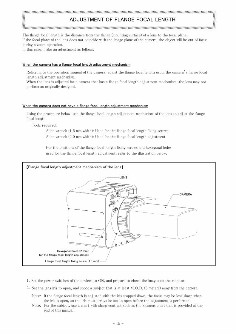
【Flange focal length adjustment mechanism of the lens】
ADJUSTMENT OF FLANGE FOCAL LENGTH
The flange focal length is the distance from the flange (mounting surface) of a lens to the focal plane.If the focal plane of the lens does not coincide with the image plane of the camera, the object will be out of focus during a zoom operation.In this case, make an adjustment as follows:
Referring to the operation manual of the camera, adjust the flange focal length using the camera’s flange focal length adjustment mechanism.When the lens is adjusted for a camera that has a flange focal length adjustment mechanism, the lens may not perform as originally designed.
Using the procedure below, use the flange focal length adjustment mechanism of the lens to adjust the flange focal length.
Tools required:
1. Set the power switches of the devices to ON, and prepare to check the images on the monitor.
2. Set the lens iris to open, and shoot a subject that is at least M.O.D. (3 meters) away from the camera.
Note:
Note:
If the flange focal length is adjusted with the iris stopped down, the focus may be less sharp when the iris is open, so the iris must always be set to open before the adjustment is performed.For the subject, use a chart with sharp contrast such as the Siemens chart that is provided at the end of this manual.
LENS
CAMERA
Hexagonal holes (2 mm) for the flange focal length adjustment
Flange focal length fixing screw (1.5 mm)
Allen wrench (1.5 mm width): Used for the flan ge focal length fixing screws
Allen wrench (2.0 mm width): Used for the flan ge focal length adjustment
For the positions of the flange focal length fixing screws and hexagonal holes
used for the flange focal length adjustment, refer to the illustration below.
- 16 -
3. Insert the Allen wrench (1.5 mm width) into the flange focal length fixing screws, and loosen the three screws
(by rotating the wrench through one complete turn).
Take care not to loosen the screws too much as they may fall out.
4. Set the zoom to the telephoto end, and operate the lens focus to bring the subject into focus.
5. Set the zoom to the wide end, insert the Allen wrench (2.0 mm width) into the hexagonal holes used for the
flange focal length adjustment, and rotate the wrench to bring the subject into focus.
6. Operate the zoom from the wide end to the telephoto end, and check whether the subject remains in focusthroughout the entire zoom range.
7.
8. Upon completion of the adjustment, insert the Allen wrench (1.5 mm width) into the flange focal length fixing
screws, and securely tighten the three screws.
If the subject does not remain in focus, repeat steps 4 to 6.
- 17 -
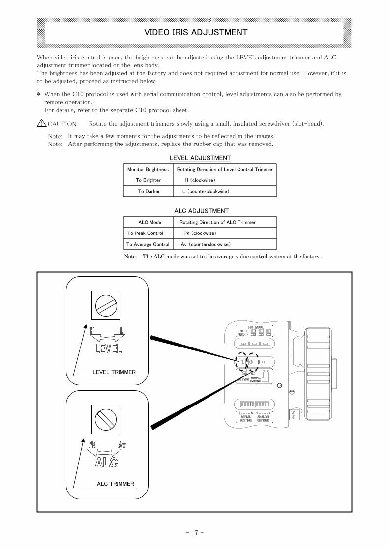
LEVEL ADJUSTMENT
Monitor Brightness Rotating Direction of Level Control Trimmer
To Brighter H (clockwise)
To Darker L (counterclockwise)
ALC ADJUSTMENT
ALC Mode Rotating Direction of ALC Trimmer
To Peak Control Pk (clockwise)
To Average Control Av (counterclockwise)
Note. The ALC mode was set to the average value control system at the factory.
LEVEL TRIMMER
ALC TRIMMER
VIDEO IRIS ADJUSTMENT
When video iris control is used, the brightness can be adjusted using the LEVEL adjustment trimmer and ALC adjustment trimmer located on the lens body.The brightness has been adjusted at the factory and does not required adjustment for normal use. However, if it is to be adjusted, proceed as instructed below.
* When the C10 protocol is used with serial communication control, level adjustments can also be performed byremote operation.For details, refer to the separate C10 protocol sheet.
CAUTION! Rotate the adjustment trimmers slowly using a small, insulated screwdriver (slot-head).
Note:Note:
It may take a few moments for the adjustments to be reflected in the images.After performing the adjustments, replace the rubber cap that was removed.
- 18 -
■ LENS CLEANING
■ CHECK CONNECTION CORDS
a. Wipe away any moisture that has collected on the outside of the lens unit.
b. Place the lens unit in a sealed vinyl bag together with a drying agent so that the agent can absorb anymoisture that remains.
Note. A new drying agent should be used for maximum effect.
MAINTENANCE
◇
◇
2
3
◇ DAILY MAINTENANCE
ELIMINATION OF WATER
INSPECTION
To avoid scratching the lens, clean it using an oil-free soft brush, a blower-brush (for photography use),or lens paper.
1
Carefully inspect outer covering and terminals for cuts, scratches or other damages.
If the moisture contained in the air is collected in the lens unit, it may produce stubborn soils on the glasses and rust on the metal parts.Remove such moisture in the following manner:
If an abnormality occurs on the lens, contact the sales agent from which you purchased the product.In order to ensure that high lens performance will be maintained for a long time to come, we recommended that periodic inspections be conducted.
- 19 -
SYMPTOM CAUSE ACTION REF. PAGE
5,8,13
12,13
-
-
-
14
-
-
15
-
18
18
-
10,11
8,9,13
10
11
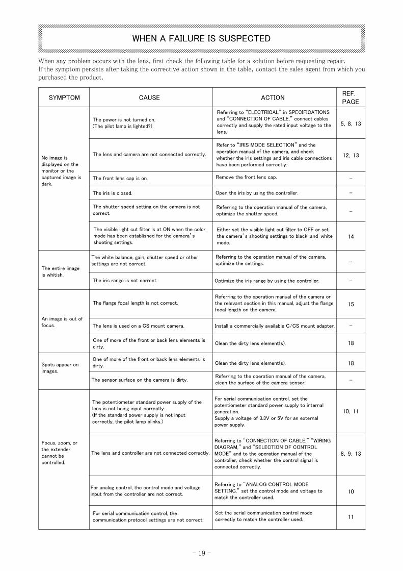
WHEN A FAILURE IS SUSPECTED
When any problem occurs with the lens, first check the following table for a solution before requesting repair.If the symptom persists after taking the corrective action shown in the table, contact the sales agent from which you purchased the product.
No image is displayed on the monitor or the captured image is dark.
The power is not turned on.(The pilot lamp is lighted?)
The lens and camera are not connected correctly.
The front lens cap is on.
The iris is closed.
The shutter speed setting on the camera is not correct.
The visible light cut filter is at ON when the color mode has been established for the camera’s shooting settings.
Referring to “ELECTRICAL” in SPECIFICATIONS and “CONNECTION OF CABLE,” connect cables correctly and supply the rated input voltage to the lens.
Refer to “IRIS MODE SELECTION” and the operation manual of the camera, and check whether the iris settings and iris cable connections have been performed correctly.
Remove the front lens cap.
Open the iris by using the controller.
Referring to the operation manual of the camera, optimize the shutter speed.
Either set the visible light cut filter to OFF or set the camera’s shooting settings to black-and-white mode.
The entire image is whitish.
The white balance, gain, shutter speed or other settings are not correct.
The iris range is not correct.
Referring to the operation manual of the camera, optimize the settings.
Optimize the iris range by using the controller.
An image is out of focus.
The flange focal length is not correct.Referring to the operation manual of the camera or the relevant section in this manual, adjust the flange focal length on the camera.
The lens is used on a CS mount camera. Install a commercially available C/CS mount adapter.
One of more of the front or back lens elements is dirty.
Clean the dirty lens element(s).
Spots appear on images.
The sensor surface on the camera is dirty.Referring to the operation manual of the camera, clean the surface of the camera sensor.
One of more of the front or back lens elements is dirty. Clean the dirty lens element(s).
Focus, zoom, or the extender cannot be controlled.
The potentiometer standard power supply of the lens is not being input correctly.(If the standard power supply is not input correctly, the pilot lamp blinks.)
For serial communication control, set the potentiometer standard power supply to internal generation.Supply a voltage of 3.3V or 5V for an external power supply.
The lens and controller are not connected correctly.
Referring to “CONNECTION OF CABLE,” “WIRING DIAGRAM,” and “SELECTION OF CONTROL MODE” and to the operation manual of the controller, check whether the control signal is connected correctly.
For analog control, the control mode and voltage input from the controller are not correct.
Referring to “ANALOG CONTROL MODE SETTING,” set the control mode and voltage to match the controller used.
For serial communication control, the communication protocol settings are not correct.
Set the serial communication control mode correctly to match the controller used.
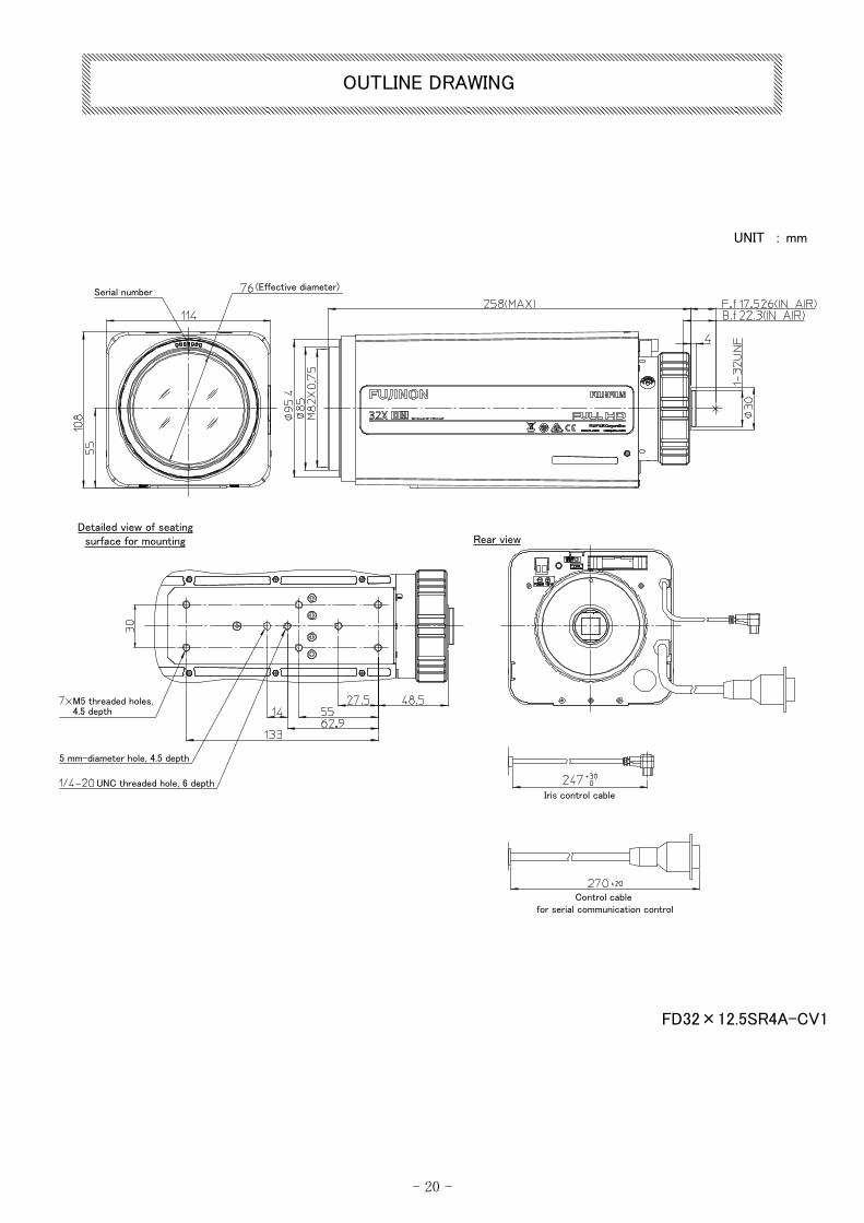
(Effective diameter)Serial number
Detailed view of seating surface for mounting Rear view
5 mm-diameter hole, 4.5 depth
UNC threaded hole, 6 depthIris control cable
Control cable for serial communication control
M5 threaded holes, 4.5 depth
FD32×12.5SR4A-CV1
UNIT : mm
- 20 -
OUTLINE DRAWING


http://www.fujifilm.com/products/optical_devices/cctv/index.htmlhttp://www.fujifilm.com/products/optical_devices/cctv/offices