Embed Size (px)
Citation preview
Operation Manual
for the D2376 3G/GSM Signal Analyser
Dycon Ltd Tel: +44 (0)1443 471 060 Fax: +44 (0)1443 479 374
Cwm Cynon Business Park – Mountain Ash – CF45 4ER - UK
www.dyconsecurity.com [email protected]
D2376 3G/GSM Signal Analyser – Operation Manual – D2376/a14/v11 - 2
Table Of Contents
1 DESCRIPTION ........................................................................................................................................... 3
2 3G/GSM SIGNAL ANALYSER CONTENTS ................................................................................................... 3
3 QUICK START GUIDE ................................................................................................................................ 4
4 SITE SURVEY ............................................................................................................................................ 6
5 FITTING A SIM CARD ................................................................................................................................ 6
5.1 ENTERING THE SIM CARD’S PIN NUMBER ...................................................................................................... 7
6 STARTUP SCREEN .................................................................................................................................... 8
7 MAIN MENU ............................................................................................................................................ 8
8 SETUP SCREEN ......................................................................................................................................... 9
9 OPTIONS ................................................................................................................................................ 10
9.1 NETWORK OPTIONS .................................................................................................................................. 11
9.2 SELECT MODE ......................................................................................................................................... 11
9.3 GPRS TEST ............................................................................................................................................. 12
10 SURVEY ................................................................................................................................................. 13
11 RESULTS ................................................................................................................................................ 14
12 MONITOR .............................................................................................................................................. 17
13 JAMMING DETECTION ........................................................................................................................... 20
14 SCREENSAVER........................................................................................................................................ 20
15 POWER-UP FUNCTIONS ......................................................................................................................... 20
16 AERIAL SITING ....................................................................................................................................... 21
17 BATTERY AND CHARGING ...................................................................................................................... 21
18 APPENDIX 1 – TROUBLE SHOOTING ....................................................................................................... 22
18.1 GSM FAULTS .......................................................................................................................................... 22
19 APPENDIX 1 - SPECIFICATION ................................................................................................................ 23
20 APPENDIX 2 - GLOSSARY OF TERMS ....................................................................................................... 24
D2376 3G/GSM Signal Analyser – Operation Manual – D2376/a14/v11 - 3
1 Description This manual documents the use of the following products:
D2376-UK – 3G 900/2100 and Dual band GSM Signal Analyser with UK plug-top charger
D2376-EU – 3G 900/2100 and Dual band GSM Signal Analyser with global plug-top charger
D2376-G – 3G 850/1900/2100 and Quad band GSM Signal Analyser with global plug-top charger
The D2376 is a Signal Analyser for use with GSM and 3G radio networks. Suitable for testing where automatic signalling equipment is used, including smart metering, any communication products and the full range of Dycon GSM/GPRS signalling equipment. It may be used to position an aerial and to test the performance of aerial systems.
The D2376 3G/GSM Signal Analyser displays mobile network information including; network provider names, cell identities, frequencies and signal strength. Jamming signals may also be detected.
The D2376 3G/GSM Signal Analyser contains a battery allowing remote operation for up to 12 hours. The internal battery may be recharged from the supplied mains power supply or a suitable car charger.
To improve battery performance and life please ensure you charge the battery for a minimum of 12hours before first use.
If the D2376 3G/GSM Signal Analyser is left switched on and unused, the unit will automatically switch off after a preset time.
The D2376 3G/GSM Signal Analyser is contained within a strong protective sleeve and is supplied complete with a charger and manual.
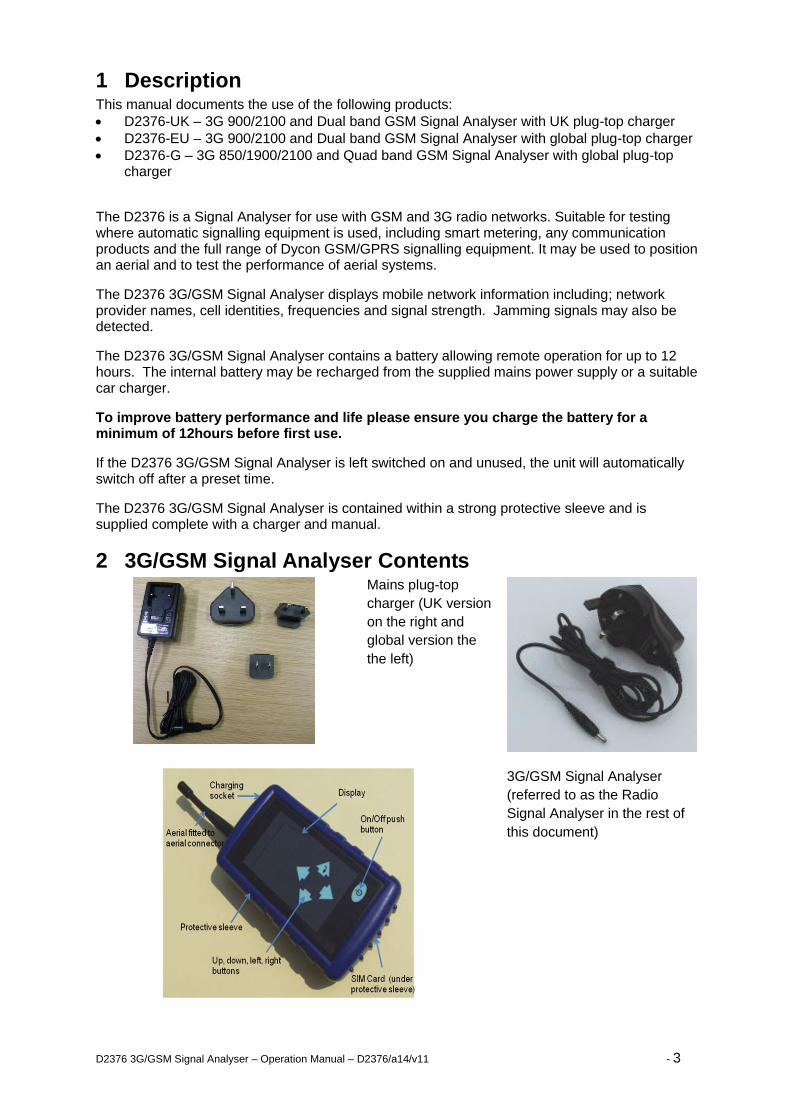
2 3G/GSM Signal Analyser Contents
Mains plug-top
charger (UK version
on the right and
global version the
the left)
3G/GSM Signal Analyser
(referred to as the Radio
Signal Analyser in the rest of
this document)
D2376 3G/GSM Signal Analyser – Operation Manual – D2376/a14/v11 - 4
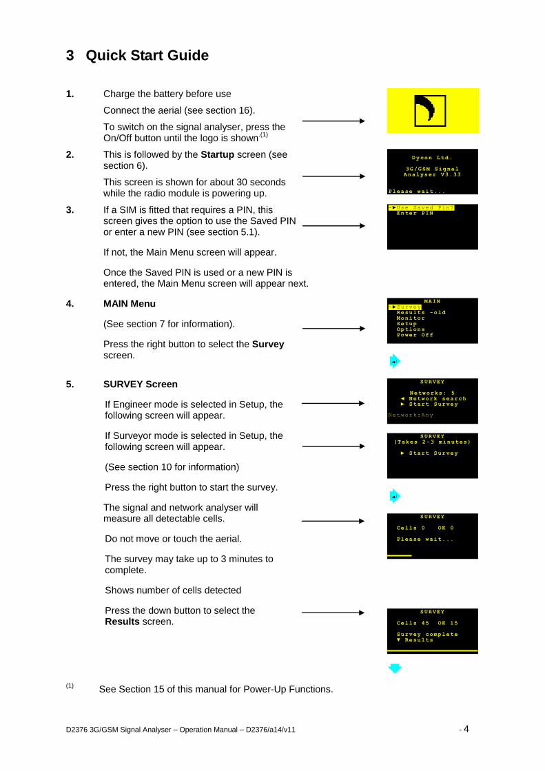
3 Quick Start Guide
1. Charge the battery before use
Connect the aerial (see section 16).
To switch on the signal analyser, press the On/Off button until the logo is shown
.(1)
2. This is followed by the Startup screen (see section 6).
This screen is shown for about 30 seconds while the radio module is powering up.
3. If a SIM is fitted that requires a PIN, this screen gives the option to use the Saved PIN or enter a new PIN (see section 5.1).
If not, the Main Menu screen will appear.
Once the Saved PIN is used or a new PIN is entered, the Main Menu screen will appear next.
4. MAIN Menu
(See section 7 for information).
Press the right button to select the Survey screen.
5. SURVEY Screen
If Engineer mode is selected in Setup, the following screen will appear.
If Surveyor mode is selected in Setup, the following screen will appear.
(See section 10 for information)
Press the right button to start the survey.
The signal and network analyser will measure all detectable cells.
Do not move or touch the aerial.
The survey may take up to 3 minutes to complete.
Shows number of cells detected
Press the down button to select the Results screen.
(1) See Section 15 of this manual for Power-Up Functions.
SURVEY Cells 45 OK 15 Survey complete ▼ Results
SURVEY Cells 0 OK 0 Please wait...
SURVEY (Takes 2-3 minutes)
► Start Survey
SURVEY
Networks: 5 ◄ Network search ► Start Survey Network:Any
Dycon Ltd.
3G/GSM Signal Analyser V3.33
Please wait...
-►Use Saved Pin?
Enter PIN
MAIN -►Survey Results -old Monitor Setup Options Power Off
Dycon Ltd
GSM Signal Analyser
V2.01
Please wait...
Dycon Ltd
GSM Signal Analyser
V2.01
Please wait...
D2376 3G/GSM Signal Analyser – Operation Manual – D2376/a14/v11 - 5
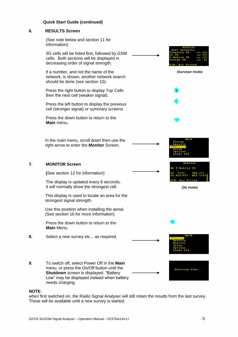
Quick Start Guide (continued)
6. RESULTS Screen
(See note below and section 11 for information)
3G cells will be listed first, followed by GSM cells. Both sections will be displayed in decreasing order of signal strength.
If a number, and not the name of the network, is shown, another network search should be done (see section 10).
Press the right button to display Top Cells then the next cell (weaker signal).
Press the left button to display the previous cell (stronger signal) or summary screens.
Press the down button to return to the Main menu.
(Surveyor mode)
In the main menu, scroll down then use the right arrow to enter the Monitor Screen.
7. MONITOR Screen
(See section 12 for information)
The display is updated every 8 seconds. It will normally show the strongest cell.
This display is used to locate an area for the strongest signal strength.
Use this position when installing the aerial. (See section 16 for more information)
Press the down button to return to the Main Menu.
(3G mode)
8. Select a new survey etc... as required.
9. To switch off, select Power Off in the Main menu, or press the On/Off button until the Shutdown screen is displayed. “Battery Low” may be displayed instead when battery needs charging.
NOTE: when first switched on, the Radio Signal Analyser will still retain the results from the last survey. These will be available until a new survey is started.
Shutting down...
MONITOR ◄► T-Mobile UK 3G 2100 dBm:27% ID:BC57837 BAT:100% SIM: Not Fitted
RESULTS Best Networks Vodafone UK G S M 54% O2 UK G S M 30% T-Mobile UK G S M 15% Orange UK G S M 9% SIM: Not Fitted
MAIN -►Survey Results Monitor Setup Options Power Off
MAIN Survey Results -►Monitor Setup Options Power Off
D2376 3G/GSM Signal Analyser – Operation Manual – D2376/a14/v11 - 6
Operating Manual
4 Site Survey It is recommended that a site survey is conducted prior to installation of any GSM or 3G equipment and associated aerial system to confirm that an adequate radio signal is available at the site.
It is particularly important that a site survey is conducted when:
a. There may be a weak signal strength at the proposed site;
b. It is known that the aerial will be fitted inside a sheet metal covered building or under a sheet metal roof;
c. The aerial will be on lower floors of buildings in heavily built-up areas.
The Radio Signal Analyser is ideal for surveying a proposed site for a suitable radio signal. Note the point of best signal. Install the aerial at this location.
Use the Radio Signal Analyser to find the point of best signal. This means maximising the signal strength.
Full details on optimising signal strength are in section 16.
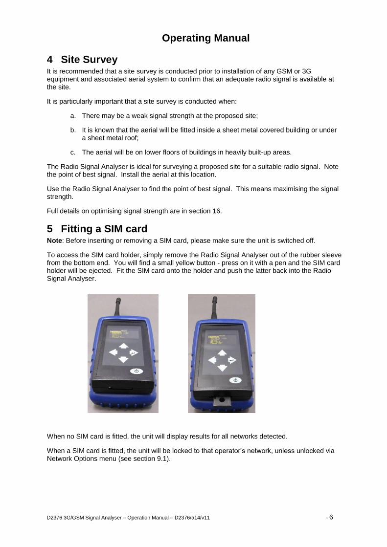
5 Fitting a SIM card Note: Before inserting or removing a SIM card, please make sure the unit is switched off.
To access the SIM card holder, simply remove the Radio Signal Analyser out of the rubber sleeve from the bottom end. You will find a small yellow button - press on it with a pen and the SIM card holder will be ejected. Fit the SIM card onto the holder and push the latter back into the Radio Signal Analyser.
When no SIM card is fitted, the unit will display results for all networks detected.
When a SIM card is fitted, the unit will be locked to that operator’s network, unless unlocked via Network Options menu (see section 9.1).
D2376 3G/GSM Signal Analyser – Operation Manual – D2376/a14/v11 - 7
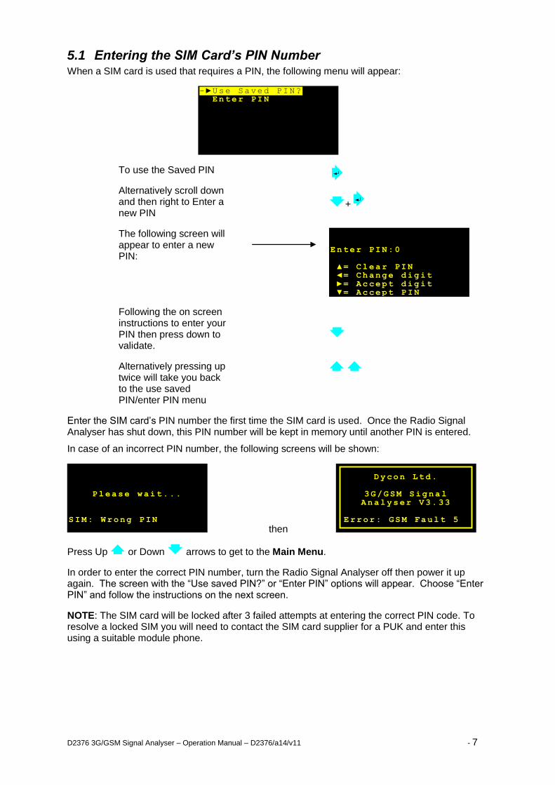
5.1 Entering the SIM Card’s PIN Number When a SIM card is used that requires a PIN, the following menu will appear:
To use the Saved PIN
Alternatively scroll down and then right to Enter a new PIN
+
The following screen will appear to enter a new PIN:
Following the on screen instructions to enter your PIN then press down to validate.
Alternatively pressing up twice will take you back to the use saved PIN/enter PIN menu
Enter the SIM card’s PIN number the first time the SIM card is used. Once the Radio Signal Analyser has shut down, this PIN number will be kept in memory until another PIN is entered.
In case of an incorrect PIN number, the following screens will be shown:
then
Press Up or Down arrows to get to the Main Menu.
In order to enter the correct PIN number, turn the Radio Signal Analyser off then power it up again. The screen with the “Use saved PIN?” or “Enter PIN” options will appear. Choose “Enter PIN” and follow the instructions on the next screen.
NOTE: The SIM card will be locked after 3 failed attempts at entering the correct PIN code. To resolve a locked SIM you will need to contact the SIM card supplier for a PUK and enter this using a suitable module phone.
-►Use Saved PIN? Enter PIN
Dycon Ltd.
3G/GSM Signal Analyser V3. 33
Error: GSM Fault 5
Please wait...
SIM: Wrong PIN
Enter PIN:0 ▲= Clear PIN ◄= Change digit ►= Accept digit ▼= Accept P IN
D2376 3G/GSM Signal Analyser – Operation Manual – D2376/a14/v11 - 8
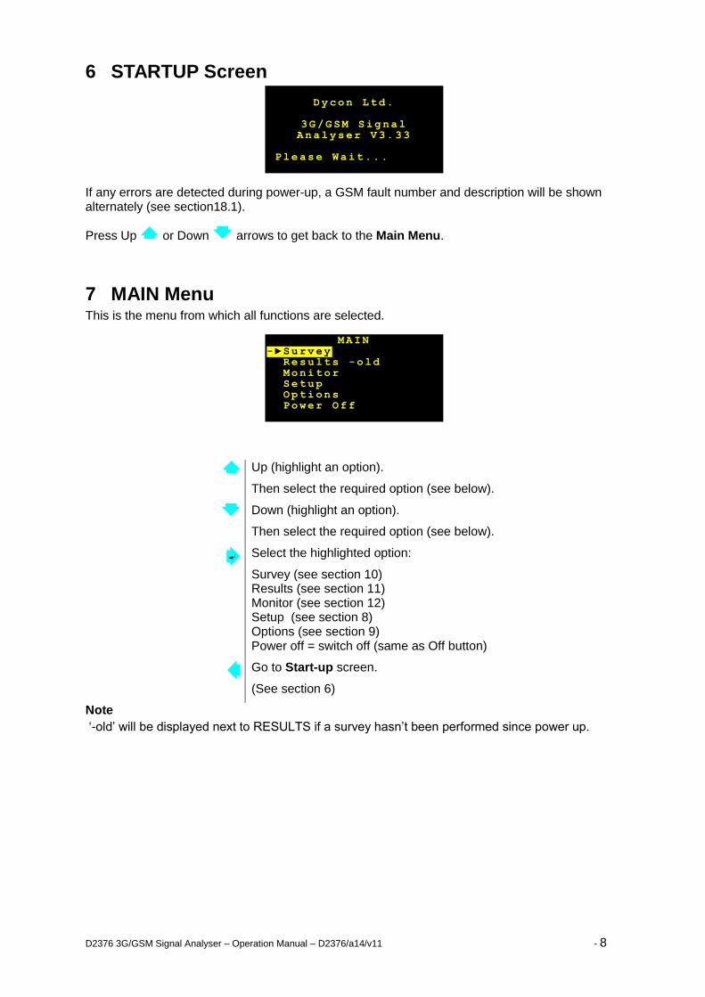
6 STARTUP Screen
If any errors are detected during power-up, a GSM fault number and description will be shown alternately (see section18.1).
Press Up or Down arrows to get back to the Main Menu.
7 MAIN Menu This is the menu from which all functions are selected.
Up (highlight an option).
Then select the required option (see below).
Down (highlight an option).
Then select the required option (see below).
Select the highlighted option:
Survey (see section 10) Results (see section 11) Monitor (see section 12) Setup (see section 8) Options (see section 9) Power off = switch off (same as Off button)
Go to Start-up screen.
(See section 6)
Note
‘-old’ will be displayed next to RESULTS if a survey hasn’t been performed since power up.
MAIN -►Survey Results -old Monitor Setup Options Power Off
Dycon Ltd.
3G/GSM Signal Analyser V3. 33
Please Wait...
D2376 3G/GSM Signal Analyser – Operation Manual – D2376/a14/v11 - 9
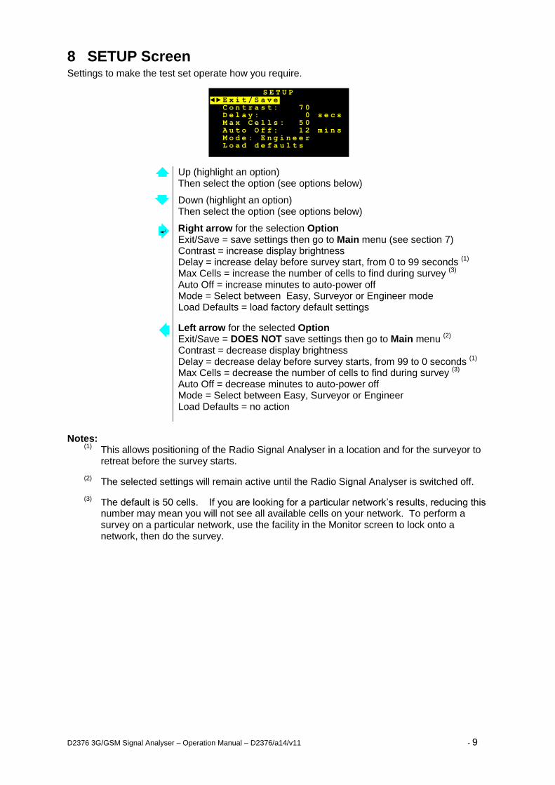
8 SETUP Screen Settings to make the test set operate how you require.
Up (highlight an option) Then select the option (see options below)
Down (highlight an option) Then select the option (see options below)
Right arrow for the selection Option Exit/Save = save settings then go to Main menu (see section 7) Contrast = increase display brightness Delay = increase delay before survey start, from 0 to 99 seconds
(1)
Max Cells = increase the number of cells to find during survey (3)
Auto Off = increase minutes to auto-power off Mode = Select between Easy, Surveyor or Engineer mode Load Defaults = load factory default settings
Left arrow for the selected Option Exit/Save = DOES NOT save settings then go to Main menu
(2)
Contrast = decrease display brightness Delay = decrease delay before survey starts, from 99 to 0 seconds
(1)
Max Cells = decrease the number of cells to find during survey (3)
Auto Off = decrease minutes to auto-power off Mode = Select between Easy, Surveyor or Engineer Load Defaults = no action
Notes:
(1) This allows positioning of the Radio Signal Analyser in a location and for the surveyor to
retreat before the survey starts.
(2) The selected settings will remain active until the Radio Signal Analyser is switched off.
(3) The default is 50 cells. If you are looking for a particular network’s results, reducing this
number may mean you will not see all available cells on your network. To perform a survey on a particular network, use the facility in the Monitor screen to lock onto a network, then do the survey.
S E T U P ◄ ► E x i t / S a v e C o n t r a s t : 7 0 D e l a y : 0 s e c s M a x C e l l s : 5 0 A u t o O f f : 1 2 m i n s M o d e : E n g i n e e r L o a d d e f a u l t s
D2376 3G/GSM Signal Analyser – Operation Manual – D2376/a14/v11 - 10
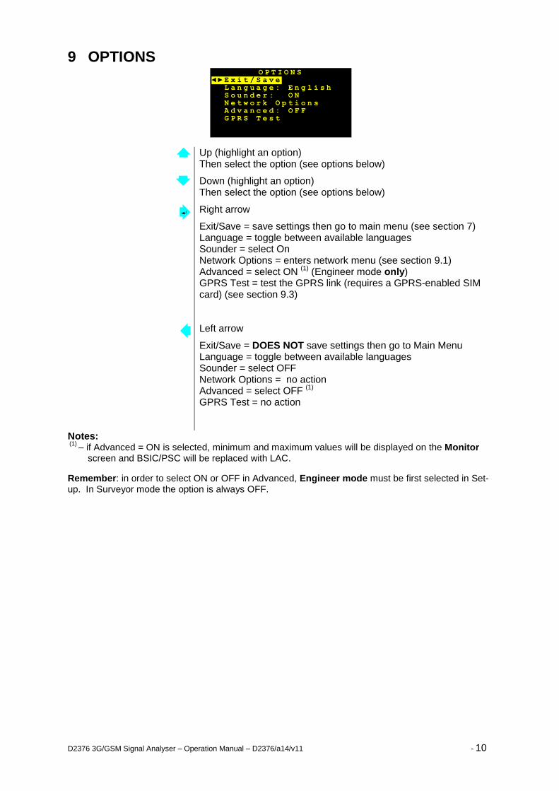
9 OPTIONS
Up (highlight an option) Then select the option (see options below)
Down (highlight an option) Then select the option (see options below)
Right arrow
Exit/Save = save settings then go to main menu (see section 7) Language = toggle between available languages Sounder = select On Network Options = enters network menu (see section 9.1) Advanced = select ON
(1) (Engineer mode only)
GPRS Test = test the GPRS link (requires a GPRS-enabled SIM card) (see section 9.3)
Left arrow
Exit/Save = DOES NOT save settings then go to Main Menu Language = toggle between available languages Sounder = select OFF Network Options = no action Advanced = select OFF
(1)
GPRS Test = no action
Notes: (1)
– if Advanced = ON is selected, minimum and maximum values will be displayed on the Monitor screen and BSIC/PSC will be replaced with LAC.
Remember: in order to select ON or OFF in Advanced, Engineer mode must be first selected in Set-up. In Surveyor mode the option is always OFF.
O P T I O N S ◄ ► E x i t / S a v e L a n g u a g e : E n g l i s h S o u n d e r : O N N e t w o r k O p t i o n s A d v a n c e d : O F F G P R S T e s t
D2376 3G/GSM Signal Analyser – Operation Manual – D2376/a14/v11 - 11
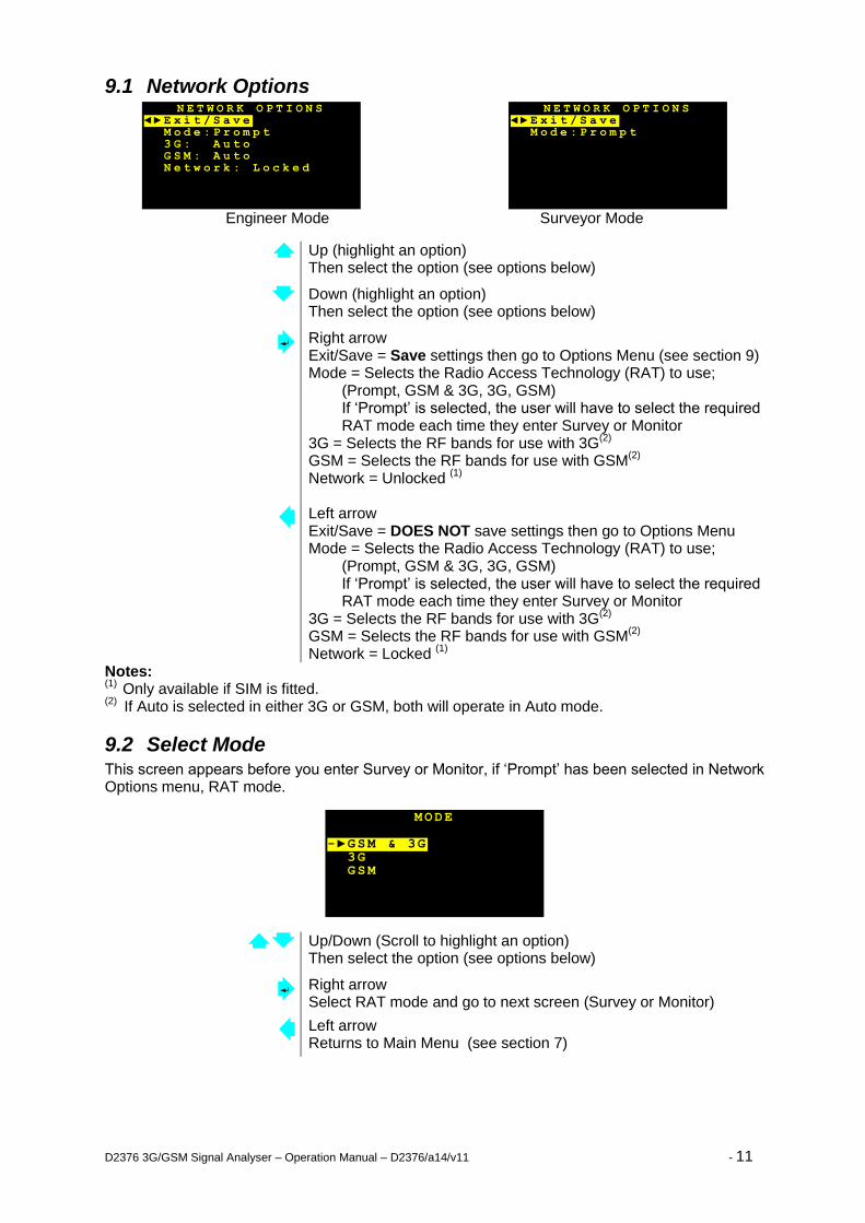
9.1 Network Options
Engineer Mode Surveyor Mode
Up (highlight an option) Then select the option (see options below)
Down (highlight an option) Then select the option (see options below)
Right arrow Exit/Save = Save settings then go to Options Menu (see section 9) Mode = Selects the Radio Access Technology (RAT) to use;
(Prompt, GSM & 3G, 3G, GSM) If ‘Prompt’ is selected, the user will have to select the required RAT mode each time they enter Survey or Monitor
3G = Selects the RF bands for use with 3G(2)
GSM = Selects the RF bands for use with GSM
(2)
Network = Unlocked (1)
Left arrow Exit/Save = DOES NOT save settings then go to Options Menu Mode = Selects the Radio Access Technology (RAT) to use;
(Prompt, GSM & 3G, 3G, GSM) If ‘Prompt’ is selected, the user will have to select the required RAT mode each time they enter Survey or Monitor
3G = Selects the RF bands for use with 3G(2)
GSM = Selects the RF bands for use with GSM
(2)
Network = Locked (1)
Notes: (1)
Only available if SIM is fitted. (2)
If Auto is selected in either 3G or GSM, both will operate in Auto mode.
9.2 Select Mode This screen appears before you enter Survey or Monitor, if ‘Prompt’ has been selected in Network Options menu, RAT mode.
Up/Down (Scroll to highlight an option) Then select the option (see options below)
Right arrow Select RAT mode and go to next screen (Survey or Monitor)
Left arrow Returns to Main Menu (see section 7)
MODE -►GSM & 3G 3G GSM
N E T W O R K O P T I O N S ◄ ► E x i t / S a v e M o d e : P r o m p t
N E T W O R K O P T I O N S ◄ ► E x i t / S a v e M o d e : P r o m p t 3 G : A u t o G S M : A u t o N e t w o r k : L o c k e d
D2376 3G/GSM Signal Analyser – Operation Manual – D2376/a14/v11 - 12
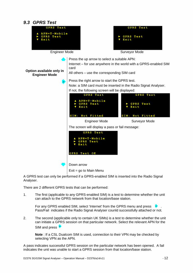
9.3 GPRS Test
Engineer Mode Surveyor Mode
Option available only in Engineer Mode
Press the up arrow to select a suitable APN:
Internet – for use anywhere in the world with a GPRS-enabled SIM card
All others – use the corresponding SIM card
Press the right arrow to start the GPRS test.
Note: a SIM card must be inserted in the Radio Signal Analyser.
If not, the following screen will be displayed:
Engineer Mode Surveyor Mode
The screen will display a pass or fail message:
Down arrow
Exit = go to Main Menu
A GPRS test can only be performed if a GPRS-enabled SIM is inserted into the Radio Signal Analyser.
There are 2 different GPRS tests that can be performed:
1. The first (applicable to any GPRS-enabled SIM) is a test to determine whether the unit can attach to the GPRS network from that location/base station.
For any GPRS enabled SIM, select 'Internet' from the GPRS menu and press . Pass/Fail indicates if the Radio Signal Analyser counld successfully attached or not.
2. The second (applicable only to certain UK SIMs) is a test to determine whether the unit can initiate a GPRS session on that particular network. Select the relevant APN for the
SIM and press
Note : If a CSL Dualcom SIM is used, connection to their VPN may be checked by selecting VPN as the APN.
A pass indicates successful GPRS session on the particular network has been opened. A fail indicates the unit was unable to start a GPRS session from that location/base station.
GPRS Test ▲ APN=T-Mobile ► GPRS Test ▼ Exit GPRS Test OK
GPRS Test ► GPRS Test ▼ Exit SIM: Not Fitted
GPRS Test ▲ APN=T-Mobile ► GPRS Test ▼ Exit SIM: Not Fitted
GPRS Test ► GPRS Test ▼ Exit
GPRS Test ▲ APN=T-Mobile ► GPRS Test ▼ Exit
GPRS Test
APN= T-Mobile
GPRS Test
D2376 3G/GSM Signal Analyser – Operation Manual – D2376/a14/v11 - 13
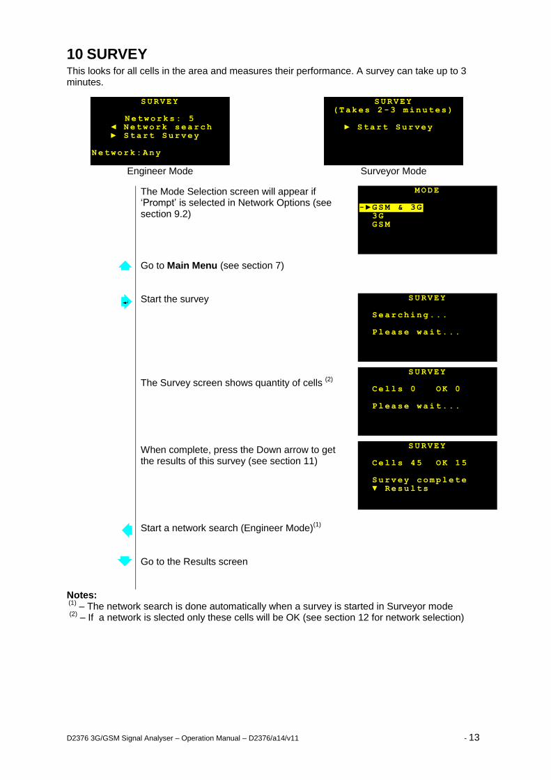
10 SURVEY This looks for all cells in the area and measures their performance. A survey can take up to 3 minutes.
Engineer Mode Surveyor Mode
The Mode Selection screen will appear if ‘Prompt’ is selected in Network Options (see section 9.2)
Go to Main Menu (see section 7)
Start the survey
The Survey screen shows quantity of cells (2)
When complete, press the Down arrow to get the results of this survey (see section 11)
Start a network search (Engineer Mode)
(1)
Go to the Results screen
Notes: (1)
– The network search is done automatically when a survey is started in Surveyor mode (2)
– If a network is slected only these cells will be OK (see section 12 for network selection)
SURVEY Cells 45 OK 15 Survey complete ▼ Results
SURVEY Cells 0 OK 0 Please wait...
SURVEY Searching... Please wait...
MODE -►GSM & 3G 3G GSM
SURVEY (Takes 2 -3 minutes)
► Start Survey
SURVEY
Networks: 5 ◄ Network search ► Start Survey Network:Any
D2376 3G/GSM Signal Analyser – Operation Manual – D2376/a14/v11 - 14
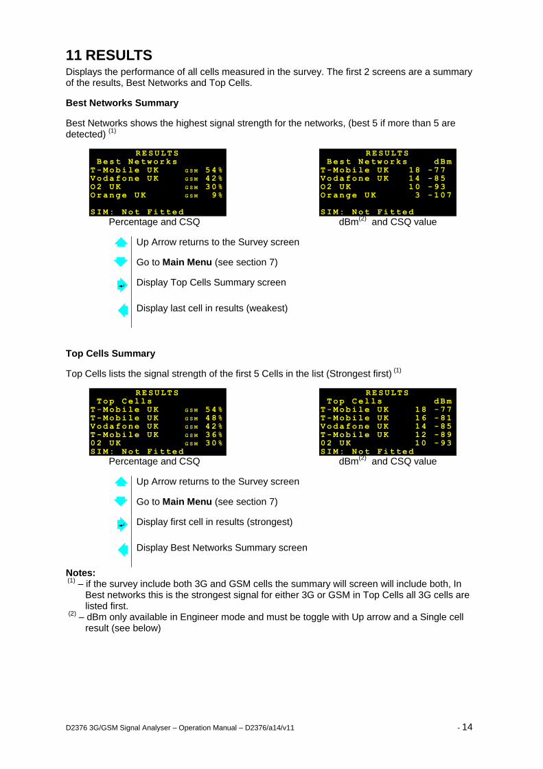
11 RESULTS Displays the performance of all cells measured in the survey. The first 2 screens are a summary of the results, Best Networks and Top Cells.
Best Networks Summary
Best Networks shows the highest signal strength for the networks, (best 5 if more than 5 are detected)
(1)
Percentage and CSQ dBm
(2) and CSQ value
Up Arrow returns to the Survey screen
Go to Main Menu (see section 7)
Display Top Cells Summary screen
Display last cell in results (weakest)
Top Cells Summary
Top Cells lists the signal strength of the first 5 Cells in the list (Strongest first) (1)
Percentage and CSQ dBm
(2) and CSQ value
Up Arrow returns to the Survey screen
Go to Main Menu (see section 7)
Display first cell in results (strongest)
Display Best Networks Summary screen
Notes: (1)
– if the survey include both 3G and GSM cells the summary will screen will include both, In Best networks this is the strongest signal for either 3G or GSM in Top Cells all 3G cells are listed first.
(2)
– dBm only available in Engineer mode and must be toggle with Up arrow and a Single cell result (see below)
RESULTS Top Cells T-Mobile UK G S M 54% T-Mobile UK G S M 48% Vodafone UK G S M 42% T-Mobile UK G S M 36% 02 UK G S M 30% SIM: Not Fitted
RESULTS Top Cells dBm T-Mobile UK 18 -77 T-Mobile UK 16 -81 Vodafone UK 14 -85 T-Mobile UK 12 -89 02 UK 10 -93 SIM: Not Fitted
RESULTS Best Networks T-Mobile UK G S M 54% Vodafone UK G S M 42% O2 UK G S M 30% Orange UK G S M 9% SIM: Not Fitted
RESULTS Best Networks dBm T-Mobile UK 18 -77 Vodafone UK 14 -85 O2 UK 1 0 -93 Orange UK 3 -107 SIM: Not Fitted
D2376 3G/GSM Signal Analyser – Operation Manual – D2376/a14/v11 - 15
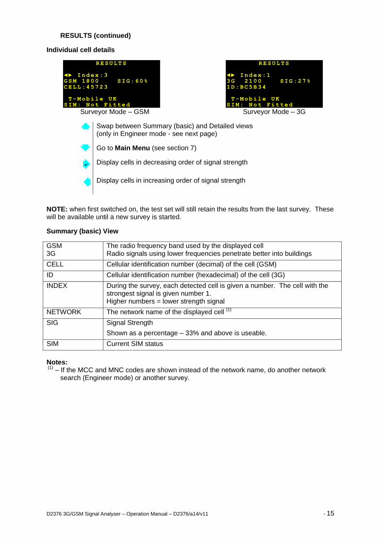
RESULTS (continued)
Individual cell details
Surveyor Mode – GSM Surveyor Mode – 3G
Swap between Summary (basic) and Detailed views (only in Engineer mode - see next page)
Go to Main Menu (see section 7)
Display cells in decreasing order of signal strength
Display cells in increasing order of signal strength
NOTE: when first switched on, the test set will still retain the results from the last survey. These will be available until a new survey is started.
Summary (basic) View
GSM 3G
The radio frequency band used by the displayed cell Radio signals using lower frequencies penetrate better into buildings
CELL Cellular identification number (decimal) of the cell (GSM)
ID Cellular identification number (hexadecimal) of the cell (3G)
INDEX During the survey, each detected cell is given a number. The cell with the strongest signal is given number 1. Higher numbers = lower strength signal
NETWORK The network name of the displayed cell (1)
SIG Signal Strength
Shown as a percentage – 33% and above is useable.
SIM Current SIM status
Notes: (1)
– If the MCC and MNC codes are shown instead of the network name, do another network search (Engineer mode) or another survey.
RESULTS ◄► Index:1 3G 2100 SIG:27% ID:BC5B34 T-Mobile UK SIM: Not Fitted
RESULTS ◄► Index:3 GSM 1800 SIG:60% CELL:45723 T-Mobile UK SIM: Not Fitted
D2376 3G/GSM Signal Analyser – Operation Manual – D2376/a14/v11 - 16
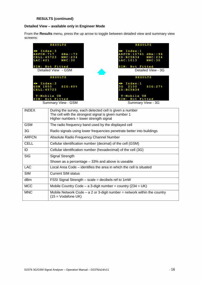
RESULTS (continued)
Detailed View – available only in Engineer Mode
From the Results menu, press the up arrow to toggle between detailed view and summary view screens:
Detailed View - GSM Detailed View - 3G
Summary View - GSM Summary View - 3G
INDEX During the survey, each detected cell is given a number The cell with the strongest signal is given number 1 Higher numbers = lower strength signal
GSM
3G
The radio frequency band used by the displayed cell
Radio signals using lower frequencies penetrate better into buildings
ARFCN Absolute Radio Frequency Channel Number
CELL Cellular identification number (decimal) of the cell (GSM)
ID Cellular identification number (hexadecimal) of the cell (3G)
SIG Signal Strength
Shown as a percentage – 33% and above is useable
LAC Local Area Code – identifies the area in which the cell is situated
SIM Current SIM status
dBm FSSI Signal Strength – scale = decibels ref to 1mW
MCC Mobile Country Code – a 3-digit number = country (234 = UK)
MNC Mobile Network Code – a 2 or 3-digit number = network within the country (15 = Vodafone UK)
RESULTS ◄► Index:3 ARFCN:717 dBm: -73 CELL:45723 MMC:234 LAC:421 MNC:30 SIM: Not Fitted
RESULTS ◄► Index:1 ARFCN:10761 dBm: -96 ID:BC5B34 MMC:234 LAC:1013 MNC:30 SIM: Not Fitted
RESULTS ◄► Index:3 GSM 1800 SIG:60% CELL:45723 T-Mobile UK SIM: Not Fitted
RESULTS ◄► Index:1 3G 2100 SIG:27% ID:BC5B34 T-Mobile UK SIM: Not Fitted
D2376 3G/GSM Signal Analyser – Operation Manual – D2376/a14/v11 - 17
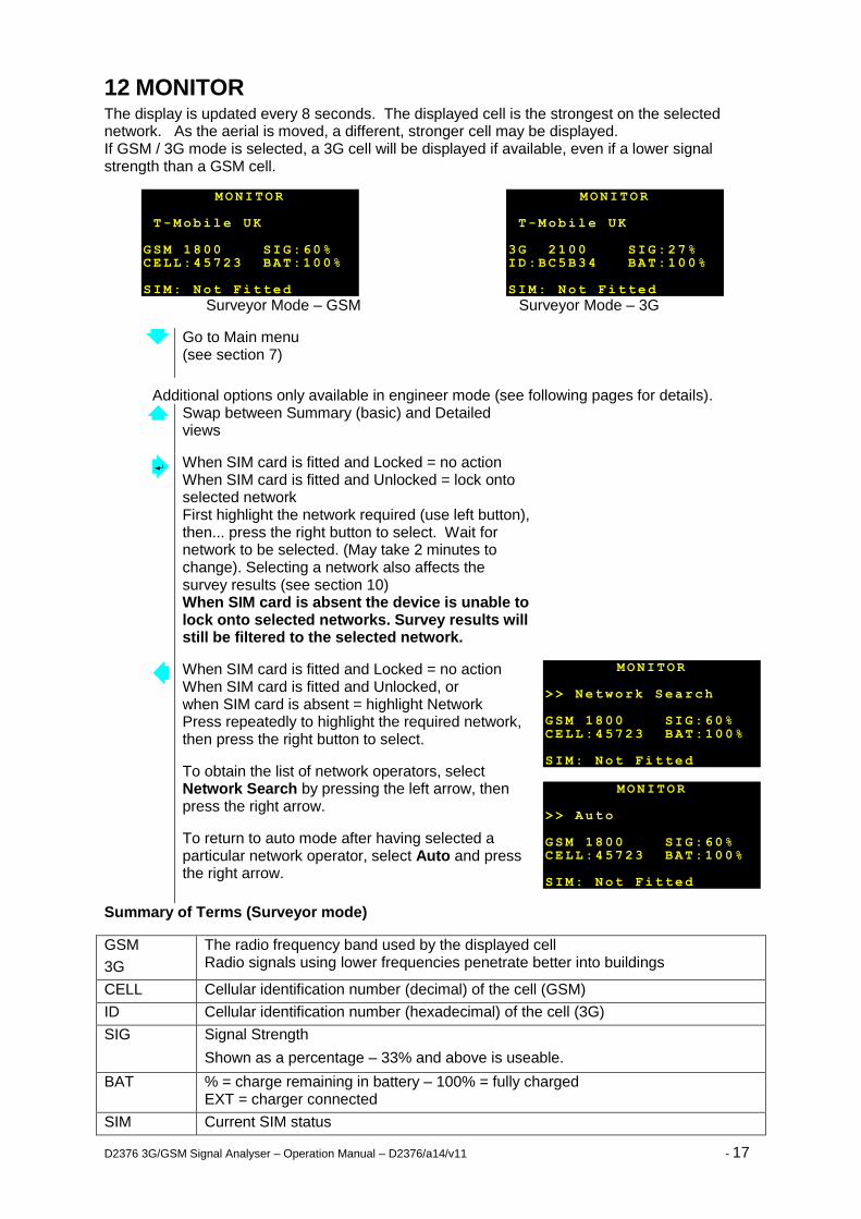
12 MONITOR The display is updated every 8 seconds. The displayed cell is the strongest on the selected network. As the aerial is moved, a different, stronger cell may be displayed. If GSM / 3G mode is selected, a 3G cell will be displayed if available, even if a lower signal strength than a GSM cell.
Surveyor Mode – GSM Surveyor Mode – 3G
Go to Main menu (see section 7)
Additional options only available in engineer mode (see following pages for details).
Swap between Summary (basic) and Detailed views
When SIM card is fitted and Locked = no action When SIM card is fitted and Unlocked = lock onto selected network First highlight the network required (use left button), then... press the right button to select. Wait for network to be selected. (May take 2 minutes to change). Selecting a network also affects the survey results (see section 10) When SIM card is absent the device is unable to lock onto selected networks. Survey results will still be filtered to the selected network.
When SIM card is fitted and Locked = no action When SIM card is fitted and Unlocked, or when SIM card is absent = highlight Network Press repeatedly to highlight the required network, then press the right button to select.
To obtain the list of network operators, select Network Search by pressing the left arrow, then press the right arrow.
To return to auto mode after having selected a particular network operator, select Auto and press the right arrow.
Summary of Terms (Surveyor mode)
GSM
3G
The radio frequency band used by the displayed cell Radio signals using lower frequencies penetrate better into buildings
CELL Cellular identification number (decimal) of the cell (GSM)
ID Cellular identification number (hexadecimal) of the cell (3G)
SIG Signal Strength
Shown as a percentage – 33% and above is useable.
BAT % = charge remaining in battery – 100% = fully charged EXT = charger connected
SIM Current SIM status
MONITOR >> Auto GSM 1800 SIG:60% CELL:45723 BAT:100% SIM: Not Fitted
MONITOR >> Network Search GSM 1800 SIG:60% CELL:45723 BAT:100% SIM: Not Fitted
MONITOR T-Mobile UK GSM 1800 SIG:60% CELL:45723 BAT:100% SIM: Not Fitted
MONITOR T-Mobile UK 3G 2100 SIG:27% ID:BC5B34 BAT:100% SIM: Not Fitted
D2376 3G/GSM Signal Analyser – Operation Manual – D2376/a14/v11 - 18
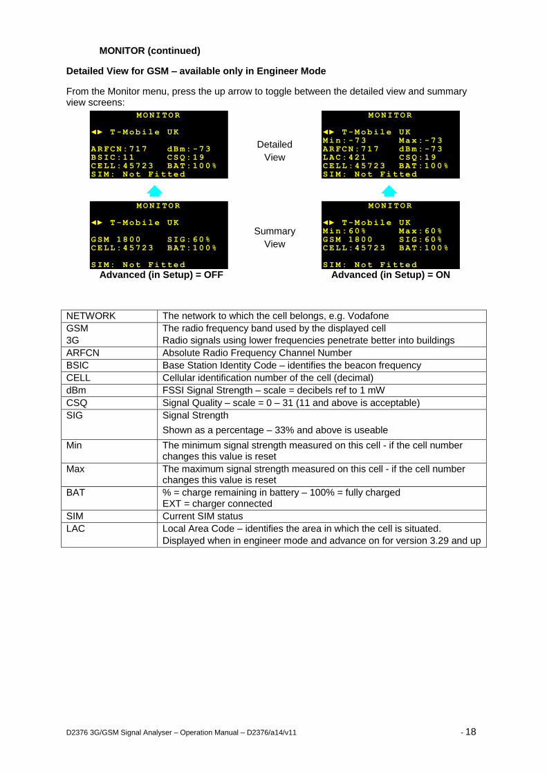
MONITOR (continued)
Detailed View for GSM – available only in Engineer Mode
From the Monitor menu, press the up arrow to toggle between the detailed view and summary view screens:
Advanced (in Setup) = OFF Advanced (in Setup) = ON
NETWORK The network to which the cell belongs, e.g. Vodafone
GSM
3G
The radio frequency band used by the displayed cell
Radio signals using lower frequencies penetrate better into buildings
ARFCN Absolute Radio Frequency Channel Number
BSIC Base Station Identity Code – identifies the beacon frequency
CELL Cellular identification number of the cell (decimal)
dBm FSSI Signal Strength – scale = decibels ref to 1 mW
CSQ Signal Quality – scale = 0 – 31 (11 and above is acceptable)
SIG Signal Strength
Shown as a percentage – 33% and above is useable
Min The minimum signal strength measured on this cell - if the cell number changes this value is reset
Max The maximum signal strength measured on this cell - if the cell number changes this value is reset
BAT % = charge remaining in battery – 100% = fully charged EXT = charger connected
SIM Current SIM status
LAC Local Area Code – identifies the area in which the cell is situated.
Displayed when in engineer mode and advance on for version 3.29 and up
MONITOR ◄► T-Mobile UK Min:60% Max:60% GSM 1800 SIG:60% CELL:45723 BAT:100% SIM: Not Fitted
MONITOR ◄► T-Mobile UK GSM 1800 SIG:60% CELL:45723 BAT:100% SIM: Not Fitted
MONITOR ◄► T-Mobile UK Min:-73 Max: -73 ARFCN:717 dBm: -73 LAC:421 CSQ: 19 CELL:45723 BAT:100% SIM: Not Fitted
MONITOR ◄► T-Mobile UK ARFCN:717 dBm: -73 BSIC:11 CSQ: 19 CELL:45723 BAT:100% SIM: Not Fitted
Summary
View
Detailed
View
D2376 3G/GSM Signal Analyser – Operation Manual – D2376/a14/v11 - 19
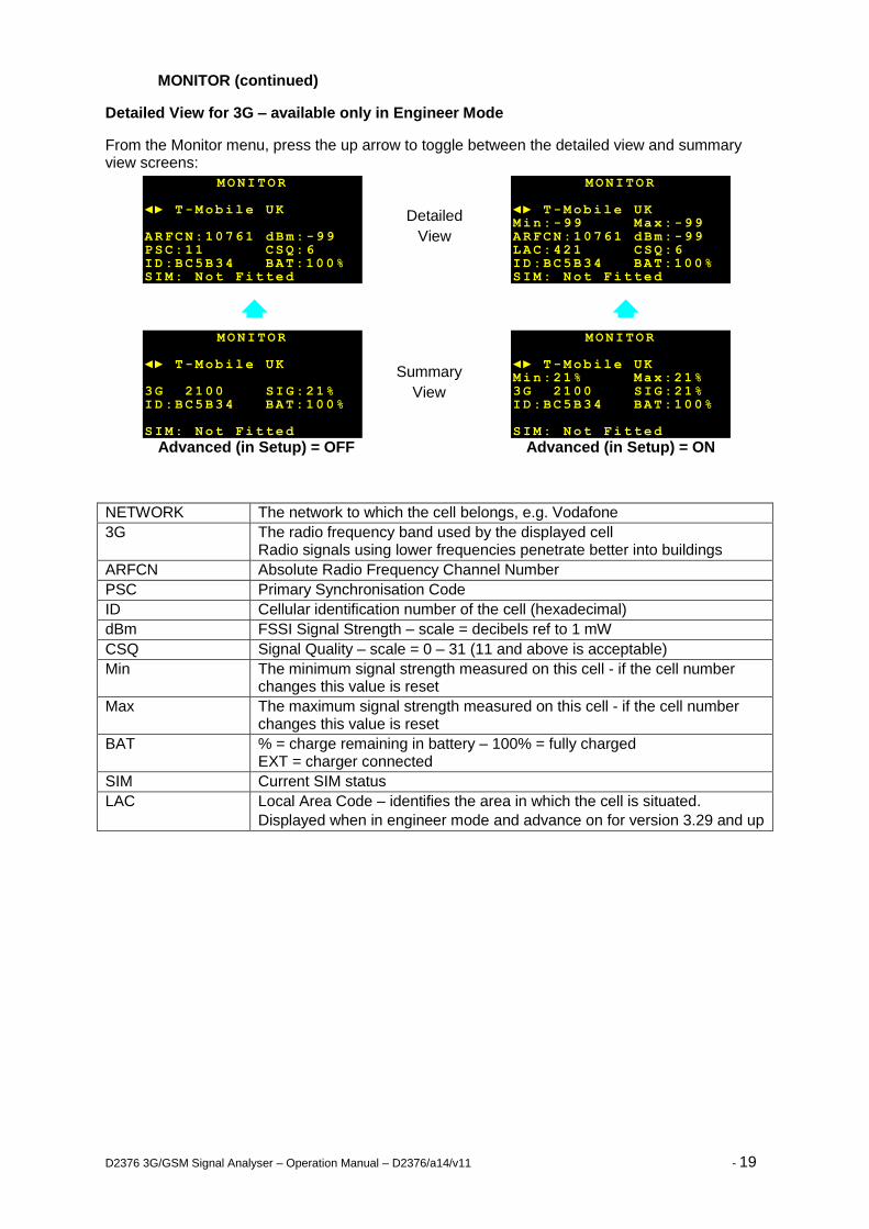
MONITOR (continued)
Detailed View for 3G – available only in Engineer Mode
From the Monitor menu, press the up arrow to toggle between the detailed view and summary view screens:
Advanced (in Setup) = OFF Advanced (in Setup) = ON
NETWORK The network to which the cell belongs, e.g. Vodafone
3G The radio frequency band used by the displayed cell Radio signals using lower frequencies penetrate better into buildings
ARFCN Absolute Radio Frequency Channel Number
PSC Primary Synchronisation Code
ID Cellular identification number of the cell (hexadecimal)
dBm FSSI Signal Strength – scale = decibels ref to 1 mW
CSQ Signal Quality – scale = 0 – 31 (11 and above is acceptable)
Min The minimum signal strength measured on this cell - if the cell number changes this value is reset
Max The maximum signal strength measured on this cell - if the cell number changes this value is reset
BAT % = charge remaining in battery – 100% = fully charged EXT = charger connected
SIM Current SIM status
LAC Local Area Code – identifies the area in which the cell is situated.
Displayed when in engineer mode and advance on for version 3.29 and up
MONITOR ◄► T-Mobile UK Min:21% Max:21% 3G 2100 SIG:21% ID:BC5B34 BAT:100% SIM: Not Fitted
MONITOR ◄► T-Mobile UK Min:-99 Max: -99 ARFCN:10761 dBm: -99 LAC:421 CSQ: 6 ID:BC5B34 BAT:100% SIM: Not Fitted
MONITOR ◄► T-Mobile UK 3G 2100 SIG:21% ID:BC5B34 BAT:100% SIM: Not Fitted
MONITOR ◄► T-Mobile UK ARFCN:10761 dBm: -99 PSC:11 CSQ: 6 ID:BC5B34 BAT:100% SIM: Not Fitted
Summary
View
Detailed
View
D2376 3G/GSM Signal Analyser – Operation Manual – D2376/a14/v11 - 20
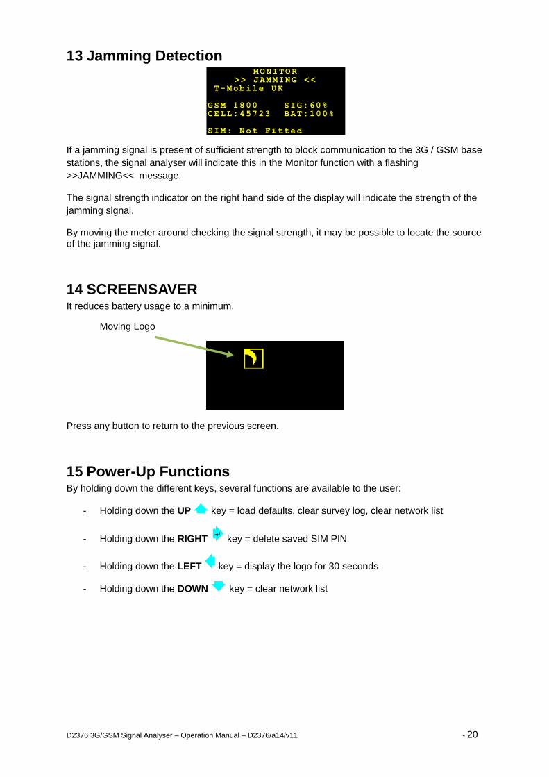
13 Jamming Detection
If a jamming signal is present of sufficient strength to block communication to the 3G / GSM base
stations, the signal analyser will indicate this in the Monitor function with a flashing
>>JAMMING<< message.
The signal strength indicator on the right hand side of the display will indicate the strength of the
jamming signal.
By moving the meter around checking the signal strength, it may be possible to locate the source of the jamming signal.
14 SCREENSAVER It reduces battery usage to a minimum.
Moving Logo
Press any button to return to the previous screen.
15 Power-Up Functions By holding down the different keys, several functions are available to the user:
- Holding down the UP key = load defaults, clear survey log, clear network list
- Holding down the RIGHT key = delete saved SIM PIN
- Holding down the LEFT key = display the logo for 30 seconds
- Holding down the DOWN key = clear network list
MONITOR >> JAMMING <<
T-Mobile UK GSM 1800 SIG:60% CELL:45723 BAT:100% SIM: Not Fitted
D2376 3G/GSM Signal Analyser – Operation Manual – D2376/a14/v11 - 21
16 Aerial Siting ALWAYS do a site survey to find the point of best signal before installation.
The aerial should normally be mounted vertically at the point of best signal. This is usually the highest point in the building (often the loft area). For security applications, the position chosen should be inside the protected area.
Large metal structures can affect radio signals. Therefore, whenever possible, avoid installing the aerial directly under sheet metal roofs or within sheet metal covered buildings because this will reduce the signal strength. If this is unavoidable, the strongest signal will be found away from the metal roof or close to large external windows or skylights.
Many large buildings closely spaced together will reduce the signal strength, particularly for aerials on the lower floors, e.g. ground floor installation in city centres. The strongest signal will normally be found close to external windows or skylights as high as possible.
Wherever possible, do not install the aerial close (2 metres) to sources of interfering signals. These include: fluorescent or neon lighting, power distribution panels, power cable runs, fridges, freezers, air-conditioning and ventilation equipment as well as electronic equipment, e.g. photocopiers, fax machines, computers, televisions...
Reliable radio operation is unlikely with low signal strength, with an incorrectly installed aerial or with strong interfering signals.
Use the Radio Signal Analyser to find the point of best signal. This means maximising the signal strength.
The supplied short black aerial is for hand-held use, i.e. site surveys.
OR
Use an aerial adapter to connect and test a remote aerial.
Remember: It is always easier to find the point of best signal before the equipment is fitted on the wall. Moving aerials, cables, trunking... after installation is wasted time and effort.
17 Battery and Charging Before first use, fully charge the battery.
When charging, use only the supplied mains plug-top power supply.
Charging will typically take 3 hours. Please ensure a full charge is given as the battery state reading can be in error after a short charge.
A fully charged battery will operate the test set for up to 12 hours.
The battery state may be read on the Monitor screen. See page 16.
When the charger is connected, the unit is always on and the On/Off button will not turn the unit off. The charger can be left plugged in indefinitely.
When the charger is disconnected, the Radio Signal Analyser will automatically switch off within one minute or after the preset time has expired.
If the Radio Signal Analyser is left switched on and unused (no buttons are being pressed), the unit will automatically switch off after a preset time to preserve the battery life. The preset time may be changed in the Setup screen. See page 9.
The internal battery is a Solid Electrolyte Lithium long type that may be transported, charged and used in any orientation. It should be protected from frost and temperatures above 40°C.
As with all rechargeable batteries, over several years, its capacity to store power will degrade. If the operational life of the battery reduces below 1 hour, contact your supplier for replacement information.
Do not attempt to open the case or remove the battery.
D2376 3G/GSM Signal Analyser – Operation Manual – D2376/a14/v11 - 22
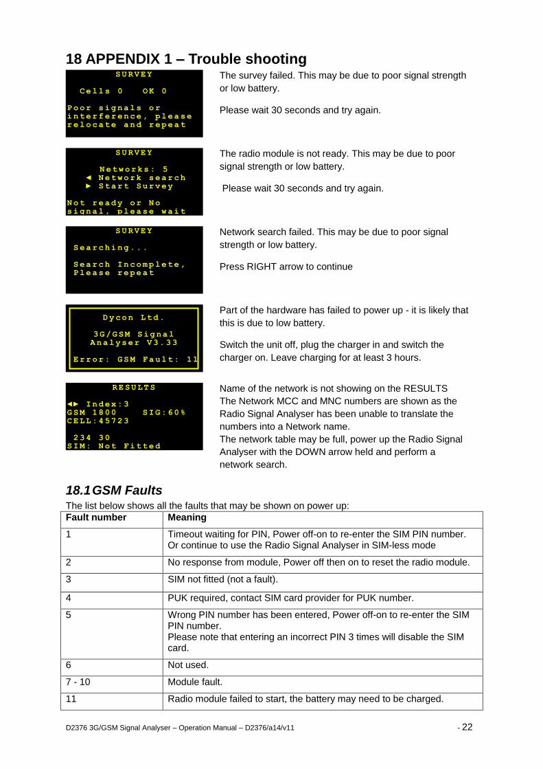
18 APPENDIX 1 – Trouble shooting
The survey failed. This may be due to poor signal strength
or low battery.
Please wait 30 seconds and try again.
The radio module is not ready. This may be due to poor
signal strength or low battery.
Please wait 30 seconds and try again.
Network search failed. This may be due to poor signal
strength or low battery.
Press RIGHT arrow to continue
Part of the hardware has failed to power up - it is likely that
this is due to low battery.
Switch the unit off, plug the charger in and switch the
charger on. Leave charging for at least 3 hours.
Name of the network is not showing on the RESULTS
The Network MCC and MNC numbers are shown as the
Radio Signal Analyser has been unable to translate the
numbers into a Network name.
The network table may be full, power up the Radio Signal
Analyser with the DOWN arrow held and perform a
network search.
18.1 GSM Faults The list below shows all the faults that may be shown on power up:
Fault number Meaning
1 Timeout waiting for PIN, Power off-on to re-enter the SIM PIN number. Or continue to use the Radio Signal Analyser in SIM-less mode
2 No response from module, Power off then on to reset the radio module.
3 SIM not fitted (not a fault).
4 PUK required, contact SIM card provider for PUK number.
5 Wrong PIN number has been entered, Power off-on to re-enter the SIM PIN number. Please note that entering an incorrect PIN 3 times will disable the SIM card.
6 Not used.
7 - 10 Module fault.
11 Radio module failed to start, the battery may need to be charged.
SURVEY
Networks: 5 ◄ Network search ► Start Survey Not ready or No signal, please wait
RESULTS ◄► Index:3 GSM 1800 SIG:60% CELL:45723 234 30 SIM: Not Fitted
Dycon Ltd.
3G/GSM Signal Analyser V3. 33
Error: GSM Fault: 11
SURVEY
Searching... Search Incomplete, Please repeat
SURVEY Cells 0 OK 0 Poor signals or interference, please relocate and repeat
D2376 3G/GSM Signal Analyser – Operation Manual – D2376/a14/v11 - 23
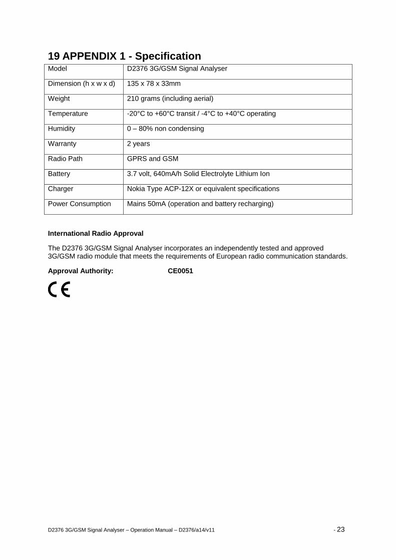
19 APPENDIX 1 - Specification Model D2376 3G/GSM Signal Analyser
Dimension (h x w x d) 135 x 78 x 33mm
Weight 210 grams (including aerial)
Temperature -20°C to +60°C transit / -4°C to +40°C operating
Humidity 0 – 80% non condensing
Warranty 2 years
Radio Path GPRS and GSM
Battery 3.7 volt, 640mA/h Solid Electrolyte Lithium Ion
Charger Nokia Type ACP-12X or equivalent specifications
Power Consumption Mains 50mA (operation and battery recharging)
International Radio Approval
The D2376 3G/GSM Signal Analyser incorporates an independently tested and approved 3G/GSM radio module that meets the requirements of European radio communication standards.
Approval Authority: CE0051
D2376 3G/GSM Signal Analyser – Operation Manual – D2376/a14/v11 - 24
20 APPENDIX 2 - Glossary of Terms
CELL – Cellular Identity Number
A number to uniquely identify each GSM/GPRS base station in the UK.
FSSI – Forward Signalling Strength Indication
This is a value indicating the radio signal strength received from the base station at a GSM communicator or the Radio Signal Analyser.
GPRS – General Packet Radio Service
A packet-based network, within the GSM system, where cost is determined by data quantity (as distinct from a circuit switched network, where cost is determined by time). Data rates range from14.4kbps, using just one of the available TDMA time slots, up to a theoretical 115 kbps when all eight time slots are used. Being a packet-switched system, the bandwidth within each GPRS cell sector will be divided between all the subscribers.
GSM – Global System for Mobile communication
A second generation cellular telecommunication system, originally for Europe, now global. A circuit-switched network, where cost is determined by time. It operates in 3 frequency bands: 900MHz, 1800MHz and 1900MHz.
3G – Third Generation System for Mobile communication
A third generation cellular telecommunication system. A packet switched network, where cost is determined by the amount of data transferred. It operates in several frequency bands: also referred to as UMTS and WCDMA.
SIM – Subscriber Identity Module
This is usually referred to as a SIM card. The SIM is the user subscription to the mobile network. The SIM contains relevant information that enables access onto the subscripted operator’s network.