Embed Size (px)
Citation preview
Optical micromanipulations inside yeast cells
Leonardo Sacconi, Iva M. Tolic-Nørrelykke, Chiara Stringari,Renzo Antolini, and Francesco S. Pavone
We present a combination of nonlinear microscopy and optical trapping applied to three-dimensionalimaging and manipulation of intracellular structures in living cells. We use Titanium-sapphire laserpulses for nonlinear microscopy of the nuclear envelope and the microtubules marked with greenfluorescent protein in fission yeast. The same laser source is also used to trap small lipid granulesnaturally present in the cell. The trapped granule is used as a handle to exert a pushing force on the cellnucleus. The granule is moved in a raster-scanning fashion to cover the area of the nucleus and hencedisplace the nucleus away from its normal position in the center of the cell. Such indirect manipulationsof an organelle (e.g., nucleus) can be useful when direct trapping of the chosen organelle is disadvanta-geous or inefficient. We show that nonlinear microscopy and optical manipulation can be performedwithout substantial damage or heating of the cell. We present this method as an important tool in cellbiology for manipulation of specific structures, as an alternative to genetic and biochemical methods. Thistechnique can be applied to several fundamental problems in cell biology, including the mechanism ofnuclear positioning and the spatial coordination of nuclear and cell division. © 2005 Optical Society ofAmerica
OCIS codes: 140.7010, 170.1420, 180.5810, 190.0190.
1. Introduction
In the last few years there has been a growing inter-est toward the use of nonlinear optical techniques forthe imaging of biological samples.1,2 With respect toconventional fluorescence, these techniques offer sev-eral advantages, including higher spatial resolution,reduced photodamage of the living sample, reducedphotobleaching of the dye, and increased penetrationdepth. For example, nonlinear microscopy is wellsuited for high-resolution imaging of intrinsic molec-ular signals in living cells and tissues,3 cell motility,4
and the distribution of a neurotransmitter in livingcells.5
On the other hand, optical manipulation tech-niques have offered new opportunities for applied re-search in biophysics and nanotecnology.6 Many of themost powerful optical manipulation techniques arederived from single-beam optical traps known as op-tical tweezers.7,8 Optical tweezers have been used forthe manipulation of viruses and cells,9,10 as well asfor displacement of intracellular organelles.9,11–13 Re-cently, Ketelaar et al.14 used optical tweezers to trapand stop the movement of the nucleus of root cells, inorder to study how cell growth depends on the loca-tion of the nucleus. Single molecules such as DNA15
and motor proteins16 have been also studied by use ofoptical tweezers.
Here we report an integration of optical tweezerswith nonlinear microscopy. We show that it is possi-ble to manipulate intracellular structure inside fis-sion yeast cells, and we analyze the trapping of lipidgranules in the cytoplasm. We show that trappingdoes not induce cell death or heating of the cell. Fi-nally, we describe an optical manipulation proceduredesigned to displace the cell nucleus away from itsnormal position in the center of the cell. This tech-nique can be used to study the mechanism of nuclearpositioning, as well as the spatial coordination of nu-clear events (chromosome segregation) and corticalactivities (cytokinesis) during cell division.
L. Sacconi ([email protected]) and R. Antolini are with theUniversity of Trento, via Sommarive 14, 38050 Povo (Trento), Ita-ly. I. M. Tolic-Nørrelykke and F. S. Pavone are with the EuropeanLaboratory for Non-linear Spectroscopy (LENS), via Nello Carrara1, 50019 Sesto Fiorentino (Florence), Italy. I. M. Tolic-Nørrelykkeis also with Rugjer Boškovic Institute, Bijeni�ka 54, 10000 Zagreb,Croatia. F. S. Pavone is also with the Department of Physics,University of Florence and Istituto Nazionale per la Fisica dellaMateria Sezione di Firenze, via Sansone 1, 50019 Sesto Fiorentino(Florence), Italy. C. Stringari is with the Department of Physics,University of Bologna, viale C. Berti Pichat 6�2, 40217 Bologna,Italy.
Received 19 July 2004; revised manuscript received 2 November2004; accepted 19 November 2004.
0003-6935/05/112001-07$15.00/0© 2005 Optical Society of America
10 April 2005 � Vol. 44, No. 11 � APPLIED OPTICS 2001
2. Materials and Methods
A. Cell Preparations
The Schizosaccharomyces pombe strain SP837 (h90
leul-32 ura4-D18 ade6-216) was transformed withthe green fluorescent protein (GFP)–fusion constructD81717 to visualize the nuclear envelope. The cellswere cultured at 30 °C on a synthetic drop-out me-dium lacking leucine (AA-leu). Visualizing the mi-totic spindle was possible with the above strain beingtransformed with the GFP-�2-tubulin fusion con-struct pDQ10518 and cultured at 30 °C on the AA-leumedium plus 2 �M thiamine. Before microscopy, thecells were resuspended in liquid AA medium andmounted on a coverslip covered with lectin BS-1(2 mg�ml, Sigma). Experiments were performed atroom temperature (21 °C–22 °C).
B. Experimental Setup
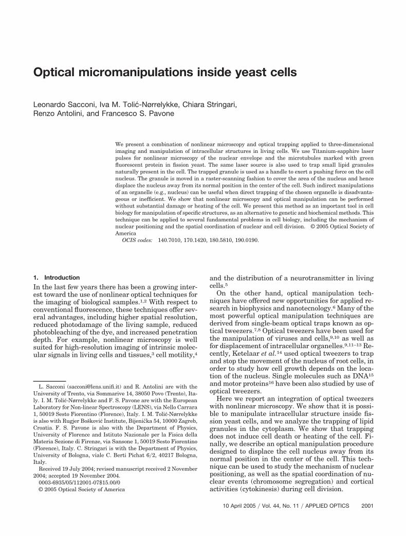
A scheme of the experimental setup is shown in Fig.1. The expanded beam of a mode-locked Titanium-sapphire laser (Mira 900F, Coherent, 100-fs pulseduration, 80-MHz repetition rate) passes through thescanning system. This system is made of two galvo-mirrors (VM500, GSI Lumunics) and a telescopic lenspair (L1 and L2) that pivot the laser beam from thefirst galvomirror (GX) to the second one (GY). L3 andTL (see Fig. 1) pivot the laser beam in the back focalplane of the microscope objective (Plan Apo 60X�1.40Oil, Nikon). The highly focalized laser beam can beused for nonlinear microscopy with the laser in themode lock (ML) configuration, or it can be used asoptical tweezers with the laser in a continuous-wave(cw) configuration. In the nonlinear microscope con-figuration, the optical sectioning (Z direction) of thesample is achieved with a piezoelectric translator (P-721, Physik Intrumente). The two-photon emission ofthe specimen is extracted from the backscattered sig-
nal by a dichroic mirror (DM), and the signal is fil-tered by an IR blocking filter (BF), focalized, andcollected by an avalanche photon diode (APD). In theoptical tweezers configuration, obtaining a strongtrap requires that the laser beam be aligned with theoptical axis of the objective by use of galvomirrors. Inthis case we use a XY piezoelectric translator (P-500,Physik Intrumente) to move the sample with respectto the optical trap. Galvomirrors and the XYZ piezo-electric translator are computer-controlled duringmicroscopy and optical manipulation experiments bya software written in LabVIEW (National Instru-ments).
A typical experiment was performed as follows.First, a three-dimensional image of the cell was takenby two-photon microscopy.19,20 Then, the laser pa-rameters were changed from the imaging configura-tion (ML mode, � � 880 nm, power in the sample�1 mW) to the trapping configuration (cw mode, �� 830 nm, power in the sample �200 mW). After theoptical manipulation, the laser parameters werechanged back to those for microscopy and a time-lapse sequence of three-dimensional images was ac-quired to visualize the effect of the manipulation andthe subsequent behavior of the cell.
3. Results and Discussion
A. Trapping of Lipid Granules
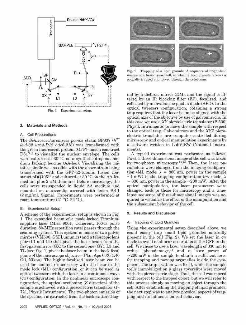
Using the experimental setup described above, wecould easily trap small lipid granules naturallypresent in the cell (Fig. 2). We set the laser in cwmode to avoid nonlinear absorption of the GFP in thecell. We chose to use a laser wavelength of 830 nm toreduce photodamage,21 and a laser power of�200 mW in the sample to obtain a sufficient forcefor trapping and moving organelles inside the cyto-plasm. The trap location was fixed, while the sample(cells immobilized on a glass coverslip) were movedwith the piezoelectric stage. Thus, the cell was movedwith respect to the trapped object, but we will refer tothis process simply as moving an object through thecell. After establishing the trapping of lipid granules,the next step was to analyze physical aspects of trap-ping and its influence on cell behavior.
Fig. 1. Experimental setup.
Fig. 2. Trapping of a lipid granule. A sequence of bright-fieldimages of a fission yeast cell, in which a lipid granule (arrow) isoptically trapped and moved through the cytoplasm.
2002 APPLIED OPTICS � Vol. 44, No. 11 � 10 April 2005
1. Maximum Trapping ForceWhen a particle is moved at a high velocity, the dragforce between the particle and its surroundings ishigher than the force exerted by the optical tweezers,hence the particle escapes from the trap.22 The max-imum force exerted by optical tweezers on a lipidgranule was estimated as the drag force at the max-imum velocity (�max) with which a trapped granulecould be moved without escaping from the trap. Thegranule was moved at velocities from 10 to 30 �m�s,and the escape velocity was found to be greater than25 �m�s. The apparent viscosity of the cytoplasmwas previously measured to be � � 0.1–0.8 Pa s.23,24
The radius of the granules (r) was estimated to be 150nm from electron micrographs of fission yeast cells.25
We estimated the force assuming Stoke’s law, F� 6�r��max � 10–60 pN. This value has to be takenwith reservation because (i) the cytoplasm is vis-coelastic and not purely viscous, though the viscousresponse dominates at time scales of 0.1 ms to 10 s,26
(ii) the Stoke’s law assumption of an infinite mediumdoes not hold in a �4 � 12 �m cell surrounded by astiff wall, and the cell wall proximity implies that thereal magnitude of the force is higher than the esti-mated value, and (iii) the cytoplasm is inhomoge-neous and the escape force may be affected by thepresence of internal membranes and organelles.
2. Cell ViabilityTo test for potential photodamage to the cell, wetrapped a lipid granule in the cell for 5 min andobserved the subsequent behavior of the cell. Trap-ping did not induce any visible damage to the cell.Yet, when the granules were trapped at a wavelengthof 880 nm (used in two-photon microscopy) instead of830 nm as usual, we observed photodamage effects (abubble forming near the trapped granule) after a fewminutes of trapping. This observation is consistentwith the finding of a photodamage minimum at 830nm and a maximum at 870 nm21 in Escherichia coli,suggesting that photodamage may be caused by asimilar mechanism in different cell types. A minorphotodamage can be expected even when a wave-length of 830 nm is used.
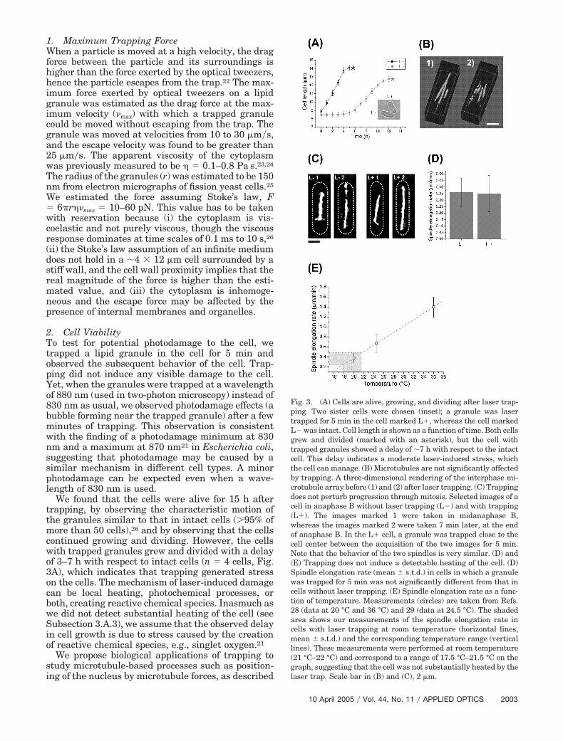
We found that the cells were alive for 15 h aftertrapping, by observing the characteristic motion ofthe granules similar to that in intact cells (�95% ofmore than 50 cells),26 and by observing that the cellscontinued growing and dividing. However, the cellswith trapped granules grew and divided with a delayof 3–7 h with respect to intact cells (n � 4 cells, Fig.3A), which indicates that trapping generated stresson the cells. The mechanism of laser-induced damagecan be local heating, photochemical processes, orboth, creating reactive chemical species. Inasmuch aswe did not detect substantial heating of the cell (seeSubsection 3.A.3), we assume that the observed delayin cell growth is due to stress caused by the creationof reactive chemical species, e.g., singlet oxygen.21
We propose biological applications of trapping tostudy microtubule-based processes such as position-ing of the nucleus by microtubule forces, as described
Fig. 3. (A) Cells are alive, growing, and dividing after laser trap-ping. Two sister cells were chosen (inset); a granule was lasertrapped for 5 min in the cell marked L, whereas the cell markedL was intact. Cell length is shown as a function of time. Both cellsgrew and divided (marked with an asterisk), but the cell withtrapped granules showed a delay of �7 h with respect to the intactcell. This delay indicates a moderate laser-induced stress, whichthe cell can manage. (B) Microtubules are not significantly affectedby trapping. A three-dimensional rendering of the interphase mi-crotubule array before (1) and (2) after laser trapping. (C) Trappingdoes not perturb progression through mitosis. Selected images of acell in anaphase B without laser trapping (L) and with trapping(L). The images marked 1 were taken in midanaphase B,whereas the images marked 2 were taken 7 min later, at the endof anaphase B. In the L cell, a granule was trapped close to thecell center between the acquisition of the two images for 5 min.Note that the behavior of the two spindles is very similar. (D) and(E) Trapping does not induce a detectable heating of the cell. (D)Spindle elongation rate (mean � s.t.d.) in cells in which a granulewas trapped for 5 min was not significantly different from that incells without laser trapping. (E) Spindle elongation rate as a func-tion of temperature. Measurements (circles) are taken from Refs.28 (data at 20 °C and 36 °C) and 29 (data at 24.5 °C). The shadedarea shows our measurements of the spindle elongation rate incells with laser trapping at room temperature (horizontal lines,mean � s.t.d.) and the corresponding temperature range (verticallines). These measurements were performed at room temperature(21 °C–22 °C) and correspond to a range of 17.5 °C–21.5 °C on thegraph, suggesting that the cell was not substantially heated by thelaser trap. Scale bar in (B) and (C), 2 �m.
10 April 2005 � Vol. 44, No. 11 � APPLIED OPTICS 2003
in Subsection 3.B. We therefore tested whether trap-ping affects microtubules. When the trapping wasperformed in interphase cells, a typical interphasearray of microtubules was visible after trapping (n� 3 cells, Fig. 3B). The microtubules showed normaldynamics of growth and shrinking. When the trap-ping was performed in cells that were dividing, themitotic spindle continued elongating at a normal rate(n � 10 cells, Figs. 3C and 3D) and the process of celldivision finished as usual. We conclude that trappingdoes not affect the dynamics of interphase microtu-bules and of the mitotic spindle, and hence it can beused to study microtubule-related processes, includ-ing those during cell division.
3. Laser-Induced Heating in the CellIn optical trap experiments an intense laser beam istightly focused at high intensities, which can induceheating of the sample.27 The temperature increase inthe focus can reach 50 K�W, depending on the prop-erties of the trapped particle and its surroundings.27
For the application of optical tweezers in the study ofcell division, as in the current research, it is essentialto estimate the overall laser-induced heating of thecell, instead of the heating in the focus. The overallheating can affect the dynamics of cell division activ-ities, whereas the extent of heating of the trappedparticle is of secondary importance, since this particleis used merely as a handle, as described (see Subsec-tion 3.B). We estimated the overall heating in the cellby investigating a well-characterized temperature-dependent process: the elongation of the mitotic spin-dle in Anaphase B.28 To examine whether trappingincreases the spindle elongation rate, we used cellswith a mitotic spindle marked by GFP (Fig. 3C). Wechose those in midanaphase B (using the imagingconfiguration of the setup), and trapped a granuleclose to the cell center for 5 min (using the trappingconfiguration). The 5-min interval was chosen be-cause the application of this method (the displace-ment of the nucleus) required trapping of the granulefor up to 5 min (see Subsection 3.B). The measuredspindle elongation rate during the period of opticaltrapping in the cell was 0.35 � 0.14 �m�min(mean � s.t.d., n � 10 cells). As a control, the spindleelongation rate in intact cells at room temperaturewas measured to be 0.36 � 0.11 �m�min (n � 14).The two groups of elongation rates (with and withouttrapping) were not significantly different (t-test, p� 0.81, Fig. 3D). The previously published spindleelongation rates are 0.38 � 0.1 �m�min at 20 °C,28
0.67 � 0.18 �m�min at 24 °C–25 °C,29 and 1.4� 0.2 �m�min at 36 °C.28 The rates measured here inthe cells with laser trapping correspond to a temper-ature range of 17.5 °C–21.5 °C, considering elonga-tion rate as a function of temperature (Fig. 3E). Theseresults indicate that the cell was not substantiallyheated by the laser trap.
B. Optically Induced Displacement of the Cell Nucleus
In fission yeast, the nucleus is positioned in the cen-ter of the cell. The site of cell division, which also
coincides with the cell center, seems determined bythe position of the predivision nucleus.30 To study themechanism of nuclear centering and the coordinationbetween the location of the nucleus and of the divi-sion plane, we set out to displace the cell nucleusaway from the cell center. Using the experimentalsetup described in Subsection 2.B, it was not possibleto optically trap the yeast nucleus, probably becauseof an insufficient difference between the refractiveindices of the nucleus and the surrounding cyto-plasm. Thus we trapped lipid granules in the cyto-plasm, also as described in Subsection 3.A, and usedthem as handles to push the nucleus.
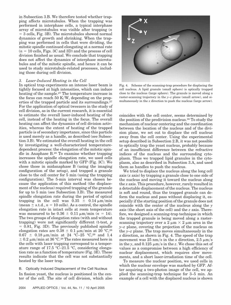
We tried to displace the nucleus along the long cellaxis (x axis) by trapping a granule close to one side ofthe nucleus and moving it toward the nucleus alongthe x axis. This procedure, however, rarely resulted ina detectable displacement of the nucleus. The nucleusis soft and round, thus the trapped granule can de-form the nucleus and pass without displacing it, es-pecially if the starting position of the granule does notcoincide with the center of the nucleus along the yaxis (the short axis of the cell) and the z axis. There-fore, we designed a scanning-trap technique in whichthe trapped granule is being moved along a raster-scanning trajectory over a 2 �m � 2 �m area in they–z plane, covering the projection of the nucleus onthe y–z plane. The trap moves simultaneously in thex direction, as shown in Fig. 4. The speed of the trapmovement was 25 nm�s in the x direction, 2.5 �m�sin the y, and 0.125 �m�s in the z. We chose this set ofvalues as a compromise between a high efficiency ofnuclear displacement, which requires slow move-ments, and a short laser-irradiation time of the cell.
To measure the nuclear position, we used cells inwhich the nuclear envelope was marked by GFP. Af-ter acquiring a two-photon image of the cell, we ap-plied the scanning-trap technique for 3–5 min. Anexample of a cell with the displaced nucleus is shown
Fig. 4. Scheme of the scanning-trap procedure for displacing thecell nucleus. A lipid granule (small sphere) is optically trappedclose to the nucleus (large sphere). The granule is moved along araster-scanning trajectory in the y–z plane (small arrow), and si-multaneously in the x direction to push the nucleus (large arrow).
2004 APPLIED OPTICS � Vol. 44, No. 11 � 10 April 2005
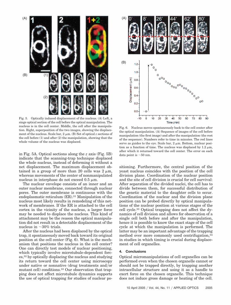
in Fig. 5A. Optical sections along the z axis (Fig. 5B)indicate that the scanning-trap technique displacedthe whole nucleus, instead of deforming it without anet displacement. The maximum displacement ob-tained in a group of more than 20 cells was 2 �m,whereas movements of the center of nonmanipulatednucleus in interphase do not exceed 0.5 �m.
The nuclear envelope consists of an inner and anouter nuclear membrane, connected through nuclearpores. The outer membrane is continuous with theendoplasmatic reticulum (ER).31 Manipulation of thenucleus most likely results in remodeling of this net-work of membranes. If the ER is attached to the cellcortex in the vicinity of the nucleus, a larger forcemay be needed to displace the nucleus. This kind ofattachment may be the reason the optical manipula-tion did not result in a detectable displacement of thenucleus in �30% trials.
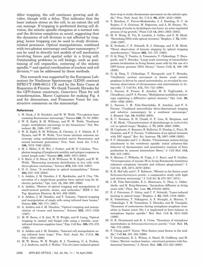
After the nucleus had been displaced by the opticaltrap, it spontaneously moved back toward its originalposition at the cell center (Fig. 6). What is the mech-anism that positions the nucleus in the cell center?One can directly test models of nuclear positioning,which typically involve microtubule-dependent forc-es,32 by optically displacing the nucleus and studyingits return toward the cell center using microscopyunder native or nonnative (drug treatments and�ormutant cell) conditions.33 Our observation that trap-ping does not affect microtubule dynamics supportsthe use of optical trapping for studies of nuclear po-
sitioning. Furthermore, the central position of theyeast nucleus coincides with the position of the celldivision plane. Coordination of the nuclear positionand the site of cell division is crucial for cell survival:After separation of the divided nuclei, the cell has todivide between them, for successful distribution ofthe genetic material to the daughter cells to occur.Coordination of the nuclear and the division planeposition can be probed directly by optical manipula-tions of the nuclear position at various stages of thecell cycle.33 Optical trapping does not affect the dy-namics of cell division and allows for observation of asingle cell both before and after the manipulation,hence it is possible to know the exact stage of the cellcycle at which the manipulation is performed. Thelatter may be an important advantage of the trappingmethod over more commonly used centrifugation,34
in studies in which timing is crucial during displace-ment of cell organelles.
4. Conclusions
Optical micromanipulations of cell organelles can beperformed even when the chosen organelle cannot orshould not be trapped directly, by trapping anotherintracellular structure and using it as a handle toexert force on the chosen organelle. This techniquedoes not induce gross damage or heating of the cell.
Fig. 5. Optically induced displacement of the nucleus. (A) Left, asinge optical section of the cell before the optical manipulation. Thenucleus is in the cell center. Middle, the cell after the manipula-tion. Right, superposition of the two images, showing the displace-ment of the nucleus. Scale bar, 2 �m. (B) Set of optical z sections ofthe cell before (1) and after (2) the manipulation, showing that thewhole volume of the nucleus was displaced.
Fig. 6. Nucleus moves spontaneously back to the cell center afterthe optical manipulation. (A) Sequence of images of the cell beforemanipulation (the first image) and after the manipulation (the restof the sequence). Numbers refer to time in minutes. The red linesserve as guides to the eye. Scale bar, 2 �m. Bottom, nuclear posi-tion as a function of time. The nucleus was displaced by 1.2 �m,after which it returned toward the cell center. The error on eachdata point is �50 nm.
10 April 2005 � Vol. 44, No. 11 � APPLIED OPTICS 2005
After trapping, the cell continues growing and di-vides, though with a delay. This indicates that thelaser induces stress on the cell, to an extent the cellcan manage. If trapping is performed during cell di-vision, the mitotic spindle elongates at a normal rateand the division completes as usual, suggesting thatthe dynamics of cell division is not affected by trap-ping; hence trapping can be used to study division-related processes. Optical manipulations, combinedwith two-photon microscopy and laser nanosurgery,20
can be used to directly test models of cell mechanicsinvolving forces and spatial order in a living cell.Outstanding problems in cell biology, such as posi-tioning of cell organelles, centering of the mitoticspindle,35 and spatial coordination of nuclear and celldivision,33 can be addressed by these methods.
This research was supported by the European Lab-oratory for Nonlinear Spectroscopy (LENS) contractHPRI-CT-1999-00111 CE and by the Ente Cassa diRisparmio di Firenze. We thank Yasushi Hiraoka forthe GFP-fusion constructs, Genevieve Thon for celltransformation, Marco Capitanio for making Fig. 4and for discussions, and Francesco Vanzi for con-structive comments on the manuscript.
References1. W. Denk, J. H. Strickler, and W. W. Webb, “Two-photon laser
scanning fluorescence microscopy,” Science 248, 73–76 (1990).2. W. R. Zipfel, R. M. Williams, and W. W. Webb, “Nonlinear
magic: multiphoton microscopy in the biosciences,” Nat. Bio-technol. 21, 1369–1377 (2003).
3. W. R. Zipfel, R. M. Williams, R. Christie, A. Y. Nikitin, B. T.Hyman, and W. W. Webb, “Live tissue intrinsic emission mi-croscopy using multiphoton-excited native fluorescence andsecond harmonic generation,” Proc. Natl. Acad. Sci. U.S.A.100, 7075–7080 (2003).
4. M. J. Miller, S. H. Wei, I. Parker, and M. D. Cahalan, “Two-photon imaging of lymphocyte motility and antigen response inintact lymph node,” Science 296, 1869–1873 (2002).
5. S. Maiti, J. B. Shear, R. M. Williams, W. R. Zipfel, and W. W.Webb, “Measuring serotonin distribution in live cells withthree-photon excitation,” Science 275, 530–532 (1997).
6. D. G. Grier, “A revolution in optical manipulation,” Nature424, 810–816 (2003).
7. A. Ashkin, J. M. Dziedzic, J. E. Bjorkholm, and S. Chu, “Ob-servation of a single-beam gradient force optical trap for di-electric particles,” Opt. Lett. 11, 288–290 (1986).
8. A. Ashkin, “History of optical trapping and manipulation ofsmall-neutral particle, atoms, and molecules,” IEEE J. Sel.Top. Quantum Electron. 6, 841–856 (2000).
9. A. Ashkin, J. M. Dziedzic, and T. Yamane, “Optical trappingand manipulation of single cells using infrared laser beams,”Nature 330, 769–771 (1987).
10. A. Ashkin and J. M. Dziedzic, “Optical trapping and manip-ulation of viruses and bacteria,” Science 235, 1517–1520(1987).
11. M. W. Berns, J. R. Aist, W. H. Wright, and H. Liang, “Opticaltrapping in animal and fungal cells using a tunable, near-infrared titanium-sapphire laser,” Exp. Cell Res. 198, 375–378(1992).
12. A. Ashkin and J. M. Dziedzic, “Internal cell manipulation us-ing infrared laser traps,” Proc. Natl. Acad. Sci. U.S.A. 86,7914–7918 (1989).
13. M. W. Berns, W. H. Wright, B. J. Tromberg, G. A. Profeta,J. J. Andrews, and R. J. Walter, “Use of a laser-induced optical
force trap to study chromosome movement on the mitotic spin-dle,” Proc. Natl. Acad. Sci. U.S.A. 86, 4539–4543 (1989).
14. T. Ketelaar, C. Faivre-Moskalenko, J. J. Esseling, N. C. deRuijter, C. S. Grierson, M. Dogterom, and A. M. Emons, “Po-sitioning of nuclei in Arabidopsis root hairs: an actin-regulatedprocess of tip growth,” Plant Cell 14, 2941–2955 (2002).
15. M. D. Wang, H. Yin, R. Landick, J. Gelles, and S. M. Block,“Stretching DNA with optical tweezers,” Biophys. J. 72, 1335–1346 (1997).
16. K. Svoboda, C. F. Schmidt, B. J. Schnapp, and S. M. Block,“Direct observation of kinesin stepping by optical trappinginterferometry,” Nature 365, 721–727 (1993).
17. D. Q. Ding, Y. Tomita, A. Yamamoto, Y. Chikashige, T. Hara-guchi, and Y. Hiraoka, “Large-scale screening of intracellularprotein localization in living fission yeast cells by the use of aGFP-fusion genomic DNA library,” Genes Cells 5, 169–190(2000).
18. D. Q. Ding, Y. Chikashige, T. Haraguchi, and Y. Hiraoka,“Oscillatory nuclear movement in fission yeast meioticprophase is driven by astral microtubules, as revealed by con-tinuous observation of chromosomes and microtubules in liv-ing cells,” J. Cell Sci. 111, 701–712 (1998).
19. L. Sacconi, E. Froner, R. Antolini, M. R. Taghizadeh, A.Choudhury, and F. S. Pavone, “Multiphoton multifocal micros-copy exploiting a diffractive optical element,” Opt. Lett. 28,1918–1920 (2003).
20. L. Sacconi, I. M. Tolic-Nørrelykke, R. Antolini, and F. S.Pavone, “Combined intracellular three-dimensional imagingand selective nanosurgery by a nonlinear microscope,”J. Biomed. Opt. 10, 014002 (2005).
21. K. C. Neuman, E. H. Chadd, G. F. Liou, K. Bergman, andS. M. Block, “Characterization of photodamage to escherichiacoli in optical traps,” Biophys. J. 77, 2856–2863 (1999).
22. M. Capitanio, G. Romano, R. Ballerini, D. Dunlap, L. Finzi, M.Giuntini, and F. S. Pavone, “Calibration of an optical tweezerswith DIC signal,” Rev. Sci. Instrum. 73, 1687–1696 (2002).
23. S. P. Alexander and C. L. Rieder, “Chromosome motion duringattachment to the vertebrate spindle: initial saltatory-likebehavior of chromosomes and quantitative analysis of forceproduction by nascent kinetochore fibers,” J. Cell Biol. 113,805–815 (1991).
24. S. Marion, C. Wilhelm, H. Voigt, J. C. Bacri, and N. Guillen,“Overexpression of myosin IB in living Entamoeba histolyticaenhances cytoplasm viscosity and reduces phagocytosis,” J.Cell Sci. 117, 3271–3279 (2004).
25. E. K. McCully and C. F. Robinow, “Mitosis in the fission yeastSchizosaccharomyces pombe: a comparative study with lightand electron microscopy,” J. Cell Sci. 9, 475–507 (1971).
26. I. M. Tolic-Nørrelykke, E.-L. Munteanu, G. Thon, L. Odder-shede, and K. Berg-Sørensen, “Anomalous diffusion in livingyeast cells,” Phys. Rev. Lett. 90, 078102 (2004).
27. E. J. Peterman, F. Gittes, and C. F. Schmidt, “Laser-inducedheating in optical traps,” Biophys. J. 84, 1308–1316 (2003).
28. K. Nabeshima, T. Nakagawa, A. F. Straight, A. Murray, Y.Chikashige, Y. M. Yamashita, Y. Hiraoka, and M. Yanagida,“Dynamics of centromeres during metaphase-anaphase tran-sition in fission yeast: Dis 1 is implicated in force balance inmetaphase bipolar spindle,” Mol. Biol. Cell 9, 3211–3225(1998).
29. D. R. Drummond and R. A. Cross, “Dynamics of interphasemicrotubules in Schizosaccharomyces pombe,” Curr. Biol. 10,766–775 (2000).
30. F. Chang and P. Nurse, “How fission yeast fission in the mid-dle,” Cell 84, 191–194 (1996).
31. Y. Gruenbaum, K. L. Wilson, A. Harel, M. Goldberg, and M.Cohen, “Review: nuclear lamins—structural proteins with fun-damental functions,” J. Struct. Biol. 129, 313–323 (2000).
2006 APPLIED OPTICS � Vol. 44, No. 11 � 10 April 2005
32. S. Reinsch and P. Gonczy, “Mechanisms of nuclear position-ing,” J. Cell Sci. 111, 2283–2295 (1998).
33. I. M. Tolic-Norrelykke, L. Sacconi, C. Stringari, and F. S.Pavone are preparing a manuscript to be called “Nuclear anddivision plane positioning studied with optical tweezers.”
34. A. Sievers and L. Heyder-Caspers, “The effect of centrifugal
accelerations on the polarity of statocytes and on the graviper-ception of cress roots,” Planta 157, 64–70 (1983).
35. I. M. Tolic-Norrelykke, L. Sacconi, G. Thon, and F. S.Pavone, “Positioning and elongation of the fission yeast spin-dle by microtubule-based pushing,” Curr Biol 14, 1181–1186(2004).
10 April 2005 � Vol. 44, No. 11 � APPLIED OPTICS 2007