Embed Size (px)
Citation preview
IEEE TRANSACTIONS ON GEOSCIENCE AND REMOTE SENSING, VOL. 52, NO. 11, NOVEMBER 2014 6999
Optimal Energy Transfer Pipe Arrangementfor Acoustic Drill String Telemetry
Lakshmi Sutha Kumar, Member, IEEE, Wei Kwang Han, Yong Liang Guan, Member, IEEE,Sumei Sun, Senior Member, IEEE, and Yee Hui Lee, Member, IEEE
Abstract—Drill string acoustic telemetry is an effective trans-mission method to retrieve downhole data. Finite-difference sim-ulations produce the comb-filter-like channel response (patternsof pass bands and stop bands) due to the presence of couplingjoints in the metallic drill string. Practical pipes used for drillingdeep wells have slight variation in length. The selection andarrangement of downhole pipes is important for improving thetransmission efficiency of extensional waves transmitted throughthe drill string. Downhole drill string channel is studied using thetransmission coefficients calculated from the transmission matrixmethod, and the resultant transfer function produces identicalresults similar to the finite-difference simulations. Reciprocity ofthe drill string structure is proved by comparing the pass bandresponses using the ascend-only (AO) and descend-only pipe ar-rangements. Transferred energies calculated up to 180 pipes ofrandom length at the end of the drill strings using transmissioncoefficients for the three different pipe arrangements, namely,AO, descend-then-ascend, and ascend-then-descend (ATD), arecompared to find the optimal pipe arrangement for single mea-surement. For the situations when pipes are distributed in sets,multiple measurements are required. In this paper, two sets ofAO and two sets of ATD arrangements are analyzed for multiplemeasurements. ATD and nxATD arrangements are proposed asoptimal pipe arrangements to produce the best possible telemetryperformance in terms of optimal acoustic energy transfer viaone- and two-way acoustic communication for single and multiplemeasurements, respectively.
Index Terms—Acoustic telemetry, comb-filter response, drillstring, finite-difference time-domain (FDTD) algorithm, pipe pe-riodicity, reciprocity principle, transfer matrix.
I. INTRODUCTION
D EEP subterranean wells are typically drilled using drillstrings assembled by pipe elements, which are approxi-
mately 10 m long, using heavy threaded tool joints. Communi-cation of information to the surface from downhole sensors ofparameters such as pressure, temperature, drilling direction, orformation is desirable. The operator can use this information for
Manuscript received October 8, 2012; revised March 26, 2013 andSeptember 23, 2013; accepted January 14, 2014. Date of publication March11, 2014. This work was supported by the Agency for Science, Technology andResearch (A∗STAR), Singapore.
L. S. Kumar, Y. L. Guan, and Y. H. Lee are with the School of Electrical andElectronic Engineering, Nanyang Technological University, Singapore 639798(e-mail: [email protected]; [email protected]; [email protected]).
W. K. Han was with Nanyang Technological University, Singapore 639798(e-mail: [email protected]).
S. Sun is with the Institute for Infocomm Research (I2R), Agency forScience, Technology and Research (A∗STAR), Singapore 138632 (e-mail:[email protected]).
Color versions of one or more of the figures in this paper are available onlineat http://ieeexplore.ieee.org.
Digital Object Identifier 10.1109/TGRS.2014.2306686
navigational purposes, to control the drill bit torque, or to abortthe mission, if necessary. Obtaining this capability translatesto increased efficiency and substantial reductions in operatingcost. Various methods of communicating that have been triedwith varying degrees of success include electromagnetic radi-ation through the ground formation [1], electrical transmissionthrough an insulated cable [2], laser communication througha fiber optic cable [3], pressure pulse propagation through thedrilling mud [4], and wave propagation through the metal drillstring [5], [6]. The electronic wire line telemetry system utilizesthe cables to transmit information from downhole to the surface.It has the advantages of real time, high speed, surface readout,and surface energy supply. However, wire line telemetry isprone to failures caused by the abrasive conditions of the mudand the wear abrasions caused by the rotation of the drill string[7], [8]. The use of special drill pipe and special tool joint con-nectors substantially increases the cost of the drilling operation.So far, mud-pulse telemetry has been the only commerciallysuccessful method. However, attenuation mechanisms in themud limit the transmission rate to less than 5 b/s. On the otherhand, due to the strong dependence of electromagnetic wavepropagation properties to the formation’s resistivity profile,electromagnetic telemetry is not a popular technique and hasvery limited applications. Among all, acoustic telemetry is oneof the promising techniques that can achieve a reliable and high-rate Logging-While-Drilling (LWD) telemetry [9], [10].
The idea of acoustic wave transmission through the drillstring was initially proposed in 1948 by Sun Oil Company, whoalso performed the first field test to measure the acoustic atten-uation of the drill string [11]. Systematic analysis of acousticwave propagation in the drill string was carried out by Barnesand Kirkwood [5] and Drumheller [6]. Several patents werelater issued on devices based on this telemetry technique [11],[12]. Pipe periodicity of the drill string structure introducesimportant impacts for wave propagation. One such impact isthe pass bands and stop bands in the frequency spectrum.The acoustic impedance mismatch in each interface causesreflection to take place at that interface. The degree to whichthey are reflected and transmitted is completely determined bythe impedance variation along the two media.
However, real drill strings are not homogeneous or exactlyperiodic. The bottom-hole assembly contains elements of dif-ferent dimensions and materials (for instance, some parts canbe made of rubber or aluminum) [13]. Drill pipes can be formedof sections with different types of tool joints and may havedifferent lengths. In practice, the pipe body may not be exactlyuniform due to manufacturing tolerance and wear. There may
0196-2892 © 2014 IEEE. Personal use is permitted, but republication/redistribution requires IEEE permission.See http://www.ieee.org/publications_standards/publications/rights/index.html for more information.
7000 IEEE TRANSACTIONS ON GEOSCIENCE AND REMOTE SENSING, VOL. 52, NO. 11, NOVEMBER 2014
be also different types of pipes for mass distribution per unitlength, often in the same drill string. However, the pipes, inmany cases, can be approximated as a periodic system ofindividual elements each formed of an elongated body with thepipe joints (tool joints) at its ends. Drumheller explained [14]that the length of all joints is constant for different sections ofthe pipe; however, there is considerable variation in the lengthof pipes among different sections because the pipe length is notaccurately controlled during the manufacture of drill pipes. Thepositions of pass bands and stop bands are decided by the pipelength of the drill string. If a drill string is assembled usingtwo pipes with different lengths, the resultant response allowswaves with frequencies located in pass bands common to bothpipe lengths.
It is disclosed in [14] and [15] that the selection andarrangement of downhole pipes plays a vital role in improvingthe transmission efficiency of extensional waves transmittedthrough the drill string for acoustic telemetry, particularlyin the high-frequency bands. The order in which the pipesbetween the transmitter and the receiver are arranged hasa significant impact on minimizing the transmission lossof signal energy from the transmitter to the receiver. If thepipes are arranged either in ascending or descending orderbased on their lengths, then peaks (or phase shifts) from theindividual pipe lengths are closer to each other, which increasethe resultant energy transfer. Pipes are arranged in ascending(descending) order based on their lengths from the source(downhole end) to the receiver (surface) for the ascend-only(AO) [descend-only (DO)] pipe arrangement. Peaks in therandom pipe arrangements are away from each other, whichreduces the resultant peak amplitudes and energy transfer.Random pipe arrangements spread the energy over a broadband of frequencies; echoes dispersed the waves and dilutedthe energy [14]. This is the reason for the selection of AO andDO pipe arrangements by Drumheller [14], [15].
It is found from the tapered dual-plane compact electromag-netic band gap microstrip filter structure [16] that ascendingfollowed by the descending [ascend-then-descend (ATD)] ar-rangement exhibits wide and smooth pass band characteristics.In this pipe arrangement, peaks (or phase shifts) from theindividual pipe lengths will be closer to one another as the pipesare either ascended or descended. In order to find the optimalpipe arrangement, in [17], four pipes with different lengths inincreasing values between 8.8683 and 9.3434 m are arranged inall 24 possible permutations. The joint lengths are kept constantas 0.4751 m in [17], and it is concluded that placing the shortestand second shortest pipes at the downhole and surface endsof the drill string gives the optimal energy transfer. Therefore,ATD arrangement, one of the ordered pipe arrangements, whichhas the shortest and second shortest pipes at the downhole andsurface ends of the drill string, is considered for analysis.
Another pipe arrangement, i.e., descending the pipes fol-lowed by ascending [descend-then-ascend (DTA)], is also con-sidered for comparison. This pipe arrangement has smoothtransition in pipe lengths from the first pipe to the last pipe,but it has the longest and second longest pipes at the downholeand surface ends of the drill string. In this paper, four orderedpipe arrangements, namely, AO, DTA, ATD, and DO, are con-
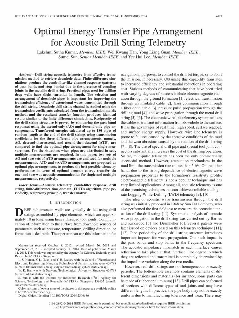
Fig. 1. Idealized drill string geometry.
sidered. For illustrative purposes, five pipes of different lengths(values of lengths in increasing order), which are numberedas 1, 2, 3, 4, and 5, respectively, are arranged using AO by“12345,” DTA by “53124,” ATD by “13542,” and DO by“54321.” Pipes are arranged using these four ways starting fromthe source (downhole) to the receiver (surface). It is stated in[18] that signal attenuation is caused by various factors such astype of pipes, type of formation, well configuration, and densityof the drilling fluid. Attenuation on drill string ranges between4 and 7 dB/1000 ft for vertical to deviated wells under normalconditions. Therefore, attenuation of 7 dB/1000 ft (0.023 dB/m)is added in the finite-difference and transmission coefficientsimulations.
Memarzadeh [19] stated that the high intensity of acousticnoise generated below 400 Hz prohibits the use of the firsttwo pass bands for reliable communication, and on the upperend, 1800 Hz is the maximum acoustic frequency that can begenerated by the transmitter’s transducer. Therefore, energiesare evaluated at the end of the drill string for different lengthdrill strings from the frequency response found (third to sixthpass bands) using the transmission coefficients by arranging thepipes in the four ways considered. The study is extended upto 180 pipes. Extensional waves, which are less dispersive, ascompared with bending and torsional waves [15], are selectedas a means for communicating information from downhole tothe surface.
II. DRILL STRING ACOUSTIC CHANNEL
A. Finite-Difference Algorithm
The drill string can be seen as a slender elastic rod, whichconsists of a number of segments. The idealized drill stringgeometry is shown in Fig. 1. As shown in Fig. 1, each pipe seg-ment has two types of elements—pipe and tool joint. The lengthof the element is d, the mass density is ρ, the cross-sectionalarea is a, and the velocity of the extensional waves is c.The acoustic wave propagation in the drill string is analyzedusing the finite-difference algorithm [6], [17]. Assume that theposition along the drill string is denoted by x and that time isdenoted by t. The mass coordinate is defined as
m =
x∫0
ρ(ζ)a(ζ)dζ (1)
KUMAR et al.: OPTIMAL ENERGY TRANSFER PIPE ARRANGEMENT FOR ACOUSTIC DRILL STRING TELEMETRY 7001
TABLE IDRILL STRING PARAMETERS
Fig. 2. Frequency response of constant pipe length drill strings.
and the impedance z = ρac. The extensional wave equation canbe deduced as [6]
∂2u
∂t2=
∂
∂m
(z2
∂u
∂m
). (2)
The wave equation (2) is discretized, and the finite-differencealgorithm can be obtained as
uj+1n + uj−1
n =2Δrn+1/2
Δrn+1/2 +Δrn−1/2ujn+1
+2Δrn−1/2
Δrn+1/2 +Δrn−1/2ujn−1 (3)
where ujn denotes the displacement field u(x, t) at position
x = xn and time t = jΔt, and n and j are the positionand the time, respectively, Δrn+1/2 denotes the string massbetween the nth and the (n+ 1)th grids, being Δrn+1/2 =ρn+1/2an+1/2Δxn+1/2.
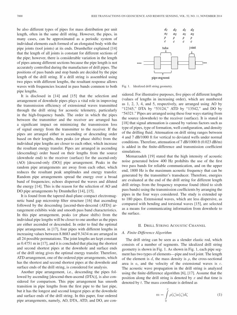
Drill string parameters are listed in Table I. Drill stringsconsisting of 10 pipes (92 m), 50 pipes (458 m), and 100 pipes(915 m) are considered. For each of the drill string, tool jointsare placed at the beginning and at the end of the drill stringand placed between the pipes. An impulse excitation signal oftime duration 30.87 μs is transmitted from the downhole, thewave displacement at the receiver is found for constant length10-, 50-, and 100-pipe drill strings using finite-difference time-domain (FDTD) algorithm, and the corresponding frequencyresponses are plotted in Fig. 2. Signal attenuation of 7 dB/1000ft is included in the simulations.
The values for ρ, a1 (area of pipe), a2 (area of joint), and clisted in Table I are used for all the simulations (Figs. 2, 4,and 5, Figs. 7(a) and (b)–9) in this paper. However, the valuesof d (d1 is the length of pipe, and d2 is the length of joint) in
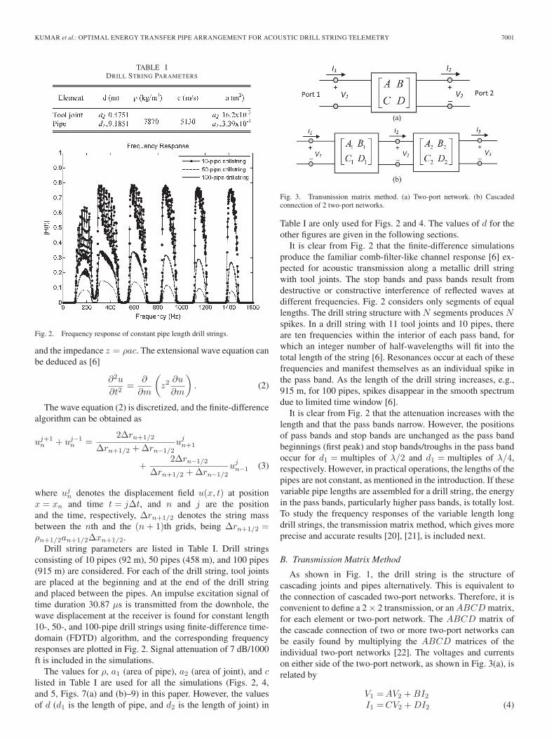
Fig. 3. Transmission matrix method. (a) Two-port network. (b) Cascadedconnection of 2 two-port networks.
Table I are only used for Figs. 2 and 4. The values of d for theother figures are given in the following sections.
It is clear from Fig. 2 that the finite-difference simulationsproduce the familiar comb-filter-like channel response [6] ex-pected for acoustic transmission along a metallic drill stringwith tool joints. The stop bands and pass bands result fromdestructive or constructive interference of reflected waves atdifferent frequencies. Fig. 2 considers only segments of equallengths. The drill string structure with N segments produces Nspikes. In a drill string with 11 tool joints and 10 pipes, thereare ten frequencies within the interior of each pass band, forwhich an integer number of half-wavelengths will fit into thetotal length of the string [6]. Resonances occur at each of thesefrequencies and manifest themselves as an individual spike inthe pass band. As the length of the drill string increases, e.g.,915 m, for 100 pipes, spikes disappear in the smooth spectrumdue to limited time window [6].
It is clear from Fig. 2 that the attenuation increases with thelength and that the pass bands narrow. However, the positionsof pass bands and stop bands are unchanged as the pass bandbeginnings (first peak) and stop bands/troughs in the pass bandoccur for d1 = multiples of λ/2 and d1 = multiples of λ/4,respectively. However, in practical operations, the lengths of thepipes are not constant, as mentioned in the introduction. If thesevariable pipe lengths are assembled for a drill string, the energyin the pass bands, particularly higher pass bands, is totally lost.To study the frequency responses of the variable length longdrill strings, the transmission matrix method, which gives moreprecise and accurate results [20], [21], is included next.
B. Transmission Matrix Method
As shown in Fig. 1, the drill string is the structure ofcascading joints and pipes alternatively. This is equivalent tothe connection of cascaded two-port networks. Therefore, it isconvenient to define a 2 × 2 transmission, or an ABCD matrix,for each element or two-port network. The ABCD matrix ofthe cascade connection of two or more two-port networks canbe easily found by multiplying the ABCD matrices of theindividual two-port networks [22]. The voltages and currentson either side of the two-port network, as shown in Fig. 3(a), isrelated by
V1 =AV2 +BI2I1 =CV2 +DI2 (4)
7002 IEEE TRANSACTIONS ON GEOSCIENCE AND REMOTE SENSING, VOL. 52, NO. 11, NOVEMBER 2014
or in matrix form as[V1
I1
]=
[A BC D
] [V2
I2
]. (5)
The transmission matrix for the lossy transmission line with thecharacteristic impedance Z0 and length l is defined as
[V1
I1
]=
[cosh(γl) Z0 sinh(γl)
sinh(γl)/Z0 cosh(γl)
] [V2
I2
](6)
where γ = α+ jβ is the complex propagation constant, α isthe attenuation factor in nepers per meter, and β = 2π/λ is the(real) propagation constant. Signal attenuation of 7 dB/1000 ftis converted into nepers per meter and is used as α in calcu-lations. The relationship between the voltages and currents oneither side of the cascaded connection of 2 two-port networksin Fig. 3(b) is given by
[V1
I1
]=
[A1 B1
C1 D1
] [A2 B2
C2 D2
] [V3
I3
]
=
[A BC D
] [V3
I3
]= M1M2
[V3
I3
](7)
where the transmission matrix, i.e., M , of the cascaded con-nection of the two networks is equal to the product of thetransmission matrices, i.e., M1 and M2, of the individual two-port networks. The transmission matrix of the tool joint (pipe),i.e., Mj (Mp), having the length d2 m (d1 m) and impedanceZj = ρa2c (Zp = ρa1c) is defined by
Mj =
[cosh(γd2) Zj sinh(γd2)1Zj
sinh(γd2) cosh(γd2)
]
Mp =
[cosh(γd1) Zp sinh(γd1)1Zp
sinh(γd1) cosh(γd1)
]. (8)
As stated in Section II-A, tool joints are placed at the beginningand at the end of the drill string and placed between the pipes.The 2 × 2 transmission matrix for the variable length drill stringwith N pipes is calculated by
M = M jMp1MjMp2 . . .MjMpNMj (9)
where Mp1,Mp2, . . . ,MpN are the transmission matrices ofthe pipes with lengths d11, d12, . . . , d1N respectively. The pipes(as well as the corresponding segments) are arranged fromdownhole to the surface end, and the transmission matrixis calculated accordingly. For convenience, the characteristicimpedance of the drill string is set to the impedance Zj of thejoint pipe, yielding that all reflections are concentrated at theends of the joints [23]. The transmission coefficient, i.e., S21 orT , of the drill string is calculated using the transmission matrixfound from (9), i.e.,
T =2
A+B/Zj + CZj +D(10)
where Zj is the characteristic impedance of the drill string.
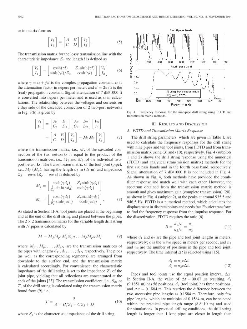
Fig. 4. Frequency response for the nine-pipe drill string using FDTD andtransmission matrix methods.
III. RESULTS AND DISCUSSION
A. FDTD and Transmission Matrix Response
The drill string parameters, which are given in Table I, areused to calculate the frequency responses for the drill stringwith nine pipes and ten tool joints, from FDTD and from trans-mission matrix using (3) and (10), respectively. Fig. 4 (subplots1 and 2) shows the drill string response using the numerical(FDTD) and analytical (transmission matrix) methods for thefirst six pass bands and in the fourth pass band, respectively.Signal attenuation of 7 dB/1000 ft is not included in Fig. 4.As shown in Fig. 4, both methods have provided the comb-filter response and match well with each other. However, thespectrum obtained from the transmission matrix method issmooth and gives maximum gain (complete transmission) [20],as shown in Fig. 4 (subplot 2), at the peaks at around 935.5 and946.5 Hz. FDTD is a numerical method, which calculates thedisplacement in discrete points and needs fast Fourier transformto find the frequency response from the impulse response. Forthe discretization, FDTD requires the ratio [6]
R =d1/c
d2/c=
n1
n2(11)
where d1 and d2 are the pipe and tool joint lengths in meters,respectively; c is the wave speed in meters per second; and n1
and n2 are the number of positions in the pipe and tool joint,respectively. The time interval Δt is selected using [15],
d1 =n1cΔtd2 =n2cΔt. (12)
Pipes and tool joints use the equal position interval Δx.In Section II-A, the value of Δt = 30.87 μs resulting, d1(9.1851 m) has 58 positions, d2 (tool joint) has three positions,and Δx = 0.1584 m. This restricts the difference between thetwo successive pipe lengths as 0.1584 m. Therefore, only fewpipe lengths, which are multiples of 0.1584 m, can be selectedwithin the practical pipe length range (8.8–10 m) and usedfor simulations. In practical drilling conditions, the drill stringlength is longer than 1 km; pipes are closer in length than
KUMAR et al.: OPTIMAL ENERGY TRANSFER PIPE ARRANGEMENT FOR ACOUSTIC DRILL STRING TELEMETRY 7003
0.1584 m. It is necessary to consider more number of pipes withless deviation in length to find the optimal pipe arrangement.The minimum possible length difference of 0.1584 m is used inthe finite-difference algorithm for Figs. 2 and 4. If this lengthdifference is further reduced to include more pipes with lengthdifferences as low as 0.01 m by reducing Δt, then FDTDneeds to work for more grids and introduces memory problemsduring simulations. FDTD’s frequency resolution is limitedto the sampling time, compared with the transmission matrixmethod. Moreover, the transmission matrix method is simpleand produces more precise response [20], [21]. Therefore, it isused for further analysis to find the optimal pipe arrangementusing more pipes; random pipe lengths with mean, i.e., μ, of9.45 m and standard deviation, i.e., σ, of 0.16 m are consideredto match with practical drill pipe lengths [15], [24]; tool jointlength is fixed as 0.5 m.
As ordering these pipes improves the energy performanceand decreases the attenuation, four different ordered pipe ar-rangements are considered. The AO and DO pipe arrangementsare included for analyzing the energy performance of the drillstring using more pipes. Ascending the pipes followed bydescending (ATD) arrangement satisfies both the conditionsrequired for the higher energy transfer, ordering the pipes basedon their length, placing the shortest and second shortest pipesat the downhole and surface ends of the drill string. Therefore,the ATD arrangement is included for analysis. Another pipearrangement, i.e., descending the pipes followed by ascending(DTA) is also considered for comparison. DTA pipe arrange-ment has smooth transition in pipe lengths from the first pipeto the last pipe, but it has the longest and second longestpipes at the downhole and surface ends of the drill string. Thepipe arrangements AO, DTA, ATD, and DO are compared for20-pipe drill string,and the frequency responses in the fourthpass band for different arrangements are analyzed next.
B. Pass Band Response for Different Pipe Arrangements
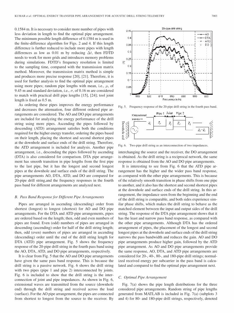
Pipes are arranged in ascending (descending) order fromshortest (longest) to longest (shortest) for AO and DO pipearrangements. For the DTA and ATD pipe arrangements, pipesare ordered based on the length; then, odd and even numbers ofpipes are found. Even (odd) numbers of pipes are arranged indescending (ascending) order for half of the drill string length;then, odd (even) numbers of pipes are arranged in ascending(descending) order until the end of the drill string length forDTA (ATD) pipe arrangement. Fig. 5 shows the frequencyresponse of the 20-pipe drill string in the fourth pass band usingthe AO, DTA, ATD, and DO pipe arrangements, respectively.
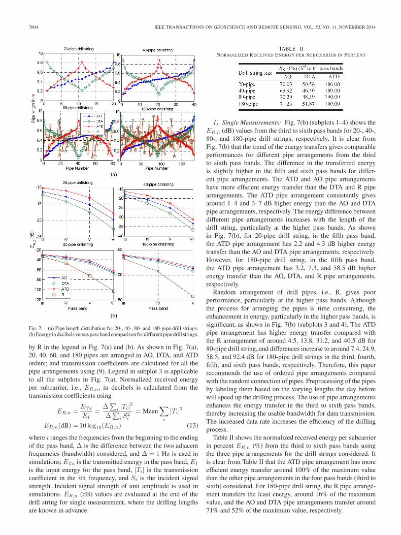
It is clear from Fig. 5 that the AO and DO pipe arrangementshave given the same pass band response. This is because thedrill string is a passive network. Fig. 6 shows the drill stringwith two pipes (pipe 1 and pipe 2) interconnected by joints.Fig. 6 is included to show that the drill string is the inter-connection of joint and pipe impedances. As shown in Fig. 6,extensional waves are transmitted from the source (downholeend) through the drill string and received across the load(surface). For the AO pipe arrangement, the pipes are connectedfrom shortest to longest from the source to the receiver. By
Fig. 5. Frequency response of the 20-pipe drill string in the fourth pass band.
Fig. 6. Two-pipe drill string as an interconnection of two impedances.
interchanging the source and the receiver, the DO arrangementis obtained. As the drill string is a reciprocal network, the sameresponse is obtained from the AO and DO pipe arrangements.
It is interesting to see from Fig. 6 that the ATD pipe ar-rangement has the higher and the wider pass band response,as compared with the other pipe arrangements. This is becauseof the relatively smooth transition in phase shifts from one pipeto another, and it also has the shortest and second shortest pipesat the downhole and surface ends of the drill string. In this ar-rangement, the impedance seen from the beginning and the endof the drill string is comparable, and both sides experience sim-ilar phase shifts, which makes the drill string to behave as thematched element between the input and output sides of the drillstring. The response of the DTA pipe arrangement shows that ithas the least and narrow pass band response, as compared withthe other pipe arrangements. Although DTA has the orderedarrangement of pipes, the placement of the longest and secondlongest pipes at the downhole and surface ends of the drill stringnarrows the pass bandwidth and reduces the gain. AO and DOpipe arrangements produce higher gain, followed by the ATDpipe arrangement. As AO and DO pipe arrangements providethe same response, AO, DTA, and ATD pipe arrangements areconsidered for 20-, 40-, 80-, and 180-pipe drill strings; normal-ized received energy per subcarrier in the pass band is calcu-lated and compared to find the optimal pipe arrangement next.
C. Optimal Pipe Arrangement
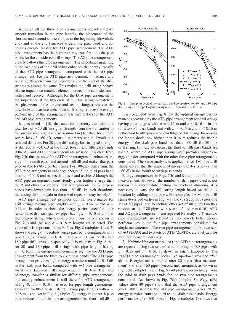
Fig. 7(a) shows the pipe length distributions for the threeconsidered pipe arrangements. Random string of pipe lengthsgenerated from MATLAB is included in Fig. 7(a) (subplots 3and 4) for 80- and 180-pipe drill strings, respectively, denoted
7004 IEEE TRANSACTIONS ON GEOSCIENCE AND REMOTE SENSING, VOL. 52, NO. 11, NOVEMBER 2014
Fig. 7. (a) Pipe length distribution for 20-, 40-, 80- and 180-pipe drill strings.(b) Energy in decibels versus pass band comparison for different pipe drill strings.
by R in the legend in Fig. 7(a) and (b). As shown in Fig. 7(a),20, 40, 60, and 180 pipes are arranged in AO, DTA, and ATDorders; and transmission coefficients are calculated for all thepipe arrangements using (9). Legend in subplot 3 is applicableto all the subplots in Fig. 7(a). Normalized received energyper subcarrier, i.e., ER,n, in decibels is calculated from thetransmission coefficients using
ER,n =ETx
EI=
Δ∑
i |Ti|2
Δ∑
i S2i
= Mean∑i
|Ti|2
ER,n(dB) = 10 log10(ER,n) (13)
where i ranges the frequencies from the beginning to the endingof the pass band, Δ is the difference between the two adjacentfrequencies (bandwidth) considered, and Δ = 1 Hz is used insimulations; ETx is the transmitted energy in the pass band, EI
is the input energy for the pass band, |Ti| is the transmissioncoefficient in the ith frequency, and Si is the incident signalstrength. Incident signal strength of unit amplitude is used insimulations. ER,n (dB) values are evaluated at the end of thedrill string for single measurement, where the drilling lengthsare known in advance.
TABLE IINORMALIZED RECEIVED ENERGY PER SUBCARRIER IN PERCENT
1) Single Measurements: Fig. 7(b) (subplots 1–4) shows theER,n (dB) values from the third to sixth pass bands for 20-, 40-,80-, and 180-pipe drill strings, respectively. It is clear fromFig. 7(b) that the trend of the energy transfers gives comparableperformances for different pipe arrangements from the thirdto sixth pass bands. The difference in the transferred energyis slightly higher in the fifth and sixth pass bands for differ-ent pipe arrangements. The ATD and AO pipe arrangementshave more efficient energy transfer than the DTA and R pipearrangements. The ATD pipe arrangement consistently givesaround 1–4 and 3–7 dB higher energy than the AO and DTApipe arrangements, respectively. The energy difference betweendifferent pipe arrangements increases with the length of thedrill string, particularly at the higher pass bands. As shownin Fig. 7(b), for 20-pipe drill string, in the fifth pass band,the ATD pipe arrangement has 2.2 and 4.3 dB higher energytransfer than the AO and DTA pipe arrangements, respectively.However, for 180-pipe drill string, in the fifth pass band,the ATD pipe arrangement has 3.2, 7.3, and 58.5 dB higherenergy transfer than the AO, DTA, and R pipe arrangements,respectively.
Random arrangement of drill pipes, i.e., R, gives poorperformance, particularly at the higher pass bands. Althoughthe process for arranging the pipes is time consuming, theenhancement in energy, particularly in the higher pass bands, issignificant, as shown in Fig. 7(b) (subplots 3 and 4). The ATDpipe arrangement has higher energy transfer compared withthe R arrangement of around 4.5, 13.8, 31.2, and 40.5 dB for80-pipe drill string, and differences increase to around 7.4, 24.9,58.5, and 92.4 dB for 180-pipe drill strings in the third, fourth,fifth, and sixth pass bands, respectively. Therefore, this paperrecommends the use of ordered pipe arrangements comparedwith the random connection of pipes. Preprocessing of the pipesby labeling them based on the varying lengths the day beforewill speed up the drilling process. The use of pipe arrangementsenhances the energy transfer in the third to sixth pass bands,thereby increasing the usable bandwidth for data transmission.The increased data rate increases the efficiency of the drillingprocess.
Table II shows the normalized received energy per subcarrierin percent ER,n (%) from the third to sixth pass bands usingthe three pipe arrangements for the drill strings considered. Itis clear from Table II that the ATD pipe arrangement has moreefficient energy transfer around 100% of the maximum valuethan the other pipe arrangements in the four pass bands (third tosixth) considered. For 180-pipe drill string, the R pipe arrange-ment transfers the least energy, around 16% of the maximumvalue, and the AO and DTA pipe arrangements transfer around71% and 52% of the maximum value, respectively.
KUMAR et al.: OPTIMAL ENERGY TRANSFER PIPE ARRANGEMENT FOR ACOUSTIC DRILL STRING TELEMETRY 7005
Although all the three pipe arrangements considered havesmooth transition in the pipe lengths, the placement of theshortest and second shortest pipes at the beginning (downholeend) and at the end (surface) widens the pass band and in-creases energy transfer for ATD pipe arrangement. The ATDpipe arrangement has the higher energy transfer at all the passbands for the considered drill strings. The AO pipe arrangementclosely follows this pipe arrangement. The impedance matchingat the two ends of the drill string enhances the energy transferof the ATD pipe arrangement compared with the AO pipearrangement. For the ATD pipe arrangement, impedance andphase shifts seen from the beginning and the end of the drillstring are almost the same. This makes the drill string behavelike an impedance-matched element between the acoustic trans-mitter and receiver. Although, for the DTA pipe arrangement,the impedance at the two ends of the drill string is matched,the placement of the longest and second longest pipes at thedownhole and surface ends of the drill string reduces the energyperformance of this arrangement less than it does for the ATDand AO pipe arrangements.
It is assumed in [10] that acoustic telemetry can tolerate atotal loss of −50 dB in signal strength from the transmitter tothe surface receiver. It is also assumed in [10] that, for a moresevere loss of −60 dB, acoustic telemetry can still work at areduced data rate. For 80-pipe drill string, loss in signal strengthis still above −50 dB at the third, fourth, and fifth pass bandsif the AO and ATD pipe arrangements are used. It is clear fromFig. 7(b) that the use of the ATD pipe arrangement enhances en-ergy in the sixth pass band around −60 dB and makes that passband usable for 80-pipe drill string. For 180-pipe drill string, theATD pipe arrangement enhances energy in the third pass bandaround −60 dB and makes that pass band usable. Although theATD pipe arrangement consistently gives higher energy thanthe R and other two ordered pipe arrangements, the other passbands have lower gain less than −60 dB. In such situations,increasing the input gain or the use of repeaters may be helpful.
ATD pipe arrangement provides optimal performance fordrill strings having pipe lengths with μ = 9.45 m and σ =0.16 m. In order to check the energy performance for otherrandomized drill strings, new pipes having σ = 0.16 m [anotherrandomized string, which is different from the one shown inFig. 7(a) and (b)] and σ = 0.18 m lengths are selected. Thevalue of μ is kept constant as 9.45 m. Fig. 8 (subplots 1 and 2)shows the energy in decibels versus pass band comparison withpipe lengths having σ = 0.16 m and σ = 0.18 m for 80- and180-pipe drill strings, respectively. It is clear from Fig. 8 thatfor 80- and 180-pipe drill strings with pipe lengths havingσ = 0.16 m, the energy enhancement is seen for the ATD pipearrangement from the third to sixth pass bands. The ATD pipearrangement provides higher energy transfer around 2 dB, 3 dBin the sixth pass band, compared with AO pipe arrangementfor 80- and 180-pipe drill strings when σ = 0.16 m. The trendof energy transfer is similar for different pipe arrangements,and energy enhancement is still there for ATD arrangementin Fig. 8, if σ = 0.18 m is used for pipe length generations.However, for 80-pipe drill string, having pipe lengths with σ =0.18 m, as shown in Fig. 8 (subplot 2), energy in the sixth passband reduces for all the pipe arrangements less than −60 dB.
Fig. 8. Energy in decibels versus pass band comparison for 80- and 180-pipedrill strings with pipe lengths having σ = 0.16 m and σ = 0.18 m.
It is concluded from Fig. 8 that the optimal energy perfor-mance is provided by the ATD pipe arrangement for drill stringshaving pipe lengths with μ = 9.45 m and σ ≤ 0.16 m in thethird to sixth pass bands and with μ = 9.45 m and σ ≤ 0.18 min the third to fifth pass bands for 80-pipe drill string. Increasingthe length deviations higher than 0.16 m reduces the usableenergy in the sixth pass band less than −60 dB for 80-pipedrill string. In these situations, the third to fifth pass bands areusable, where the ATD pipe arrangement provides higher en-ergy transfer compared with the other three pipe arrangementsconsidered. The same analysis is applicable for 180-pipe drillstring, except that the amount of energy transfer is lower than−60 dB in the fourth to sixth pass bands.
Energy comparisons in Figs. 7(b) and 8 are plotted for singlemeasurement. However, the number of drill pipes used is notknown in advance while drilling. In practical situations, it isnecessary to vary the drill string length based on the oil’slocation by adding more pipes. For example, the 80-pipe drillstring described earlier in Fig. 7(a) and (b) (subplot 3) uses oneset of 80 pipes, and to include other set of 80 pipes (anotherrandom string of 80 pipes with μ = 9.45 and σ = 0.16), ATDand AO pipe arrangements are repeated for analysis. These twopipe arrangements are selected as they provide better energyperformances in the four pipe arrangements considered forsingle measurement. The two pipe arrangements, i.e., two setsof AO (2xAO) and two sets of ATD (2xATD), are analyzed formultiple measurements next.
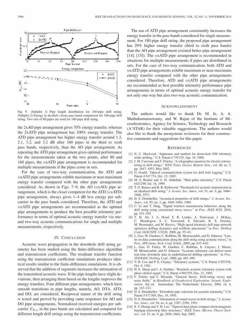
2) Multiple Measurements: AO and ATD pipe arrangementsare repeated using two sets of random strings of 80 pipes withμ = 9.45 and σ = 0.16, as shown in Fig. 9 (subplot 1). The2xATD pipe arrangement looks like up–down reversed “W”shape. Energies are compared after 80 pipes (first measure-ment) and after 160 pipes (second measurement), as shown inFig. 7(b) (subplot 3) and Fig. 9 (subplot 2), respectively, fromthe third to sixth pass bands for the two pipe arrangementsconsidered. As shown in Fig. 7(b) (subplot 3), ER,n (dB)values after 80 pipes show that the ATD pipe arrangementgives 100%, whereas the AO pipe arrangement gives 70.2%energy transfer from the third to the sixth pass bands. Energyperformance after 160 pipes in Fig. 9 (subplot 2) shows that
7006 IEEE TRANSACTIONS ON GEOSCIENCE AND REMOTE SENSING, VOL. 52, NO. 11, NOVEMBER 2014
Fig. 9. (Subplot 1) Pipe length distribution for 160-pipe drill string.(Subplot 2) Energy in decibels versus pass band comparison for 160-pipe drillstring. Two sets of 80 pipes are used for 160-pipe drill string.
the 2xAO pipe arrangement gives 70% energy transfer, whereasthe 2xATD pipe arrangement has 100% energy transfer. TheATD pipe arrangement has higher energy transfer around 1.3,2.1, 3.2, and 3.2 dB after 160 pipes in the third to sixthpass bands, respectively, than the AO pipe arrangement. Asrepeating the ATD pipe arrangement gives optimal performancefor the measurements taken at the two points, after 80 and160 pipes, the nxATD pipe arrangement is recommended formultiple measurements if the pipes come in sets.
For the case of two-way communication, the ATD andnxATD pipe arrangements exhibit maximum or near-maximumenergy transfer compared with the other pipe arrangementsconsidered. As shown in Figs. 7–9, the AO (nxAO) pipe ar-rangement, which is the closer competent for the ATD (nxATD)pipe arrangement, always gives 1–4 dB less energy per sub-carrier in the pass bands considered. Therefore, the ATD andnxATD pipe arrangements are recommended as the optimalpipe arrangements to produce the best possible telemetry per-formance in terms of optimal acoustic energy transfer via one-and two-way acoustic communications for single and multiplemeasurements, respectively.
IV. CONCLUSION
Acoustic wave propagation in the downhole drill string ge-ometry has been studied using the finite-difference algorithmand transmission coefficients. The resultant transfer functionusing the transmission coefficient simulations produces iden-tical results similar to the finite-difference simulations. It is ob-served that the addition of segments increases the attenuation ofthe transmitted acoustic wave. If the pipe lengths have slight de-viations, then arranging them based on the lengths improves theenergy transfers. Four different pipe arrangements, which havesmooth transitions in pipe lengths, namely, AO, DTA, ATD,and DO, are considered. Reciprocal nature of the drill stringis tested and proved by providing same responses for AO andDO pipe arrangements. Normalized received energies per sub-carrier ER,n in the pass bands are calculated and compared fordifferent length drill strings using the transmission coefficients.
The use of ATD pipe arrangement consistently increases theenergy transfer in the pass bands considered for single measure-ment. For 180-pipe drill string, the proposed pipe arrangementhas 29% higher energy transfer (third to sixth pass bands)than the AO pipe arrangement (existed better pipe arrangement[14], [15]). The nxATD pipe arrangement is recommended insituations for multiple measurements if pipes are distributed insets. For the case of two-way communication, both ATD andnxATD pipe arrangements exhibit maximum or near-maximumenergy transfer compared with the other pipe arrangementsconsidered. Therefore, ATD and nxATD pipe arrangementsare recommended as best possible telemetry performance pipearrangements in terms of optimal acoustic energy transfer fornot only one-way but also two-way acoustic communication.
ACKNOWLEDGMENT
The authors would like to thank Dr. M. Je, A. A.Muthukumaraswamy, and W. Rajan of the Institute of Mi-croelectronics, Agency for Science, Technology and Research(A∗STAR) for their valuable suggestions. The authors wouldalso like to thank the anonymous reviewers for their construc-tive comments and suggestions for this paper.
REFERENCES
[1] N. C. MacLeod, “Apparatus and method for down-hole EM telemetrywhile drilling,” U.S. Patent 4 739 325, Apr. 19, 1988.
[2] J. M. Carcione and F. Poletto, “A telegrapher equation for electric teleme-tering in drill strings,” IEEE Trans. Geosci. Remote Sens., vol. 40, no. 5,pp. 1047–1053, May 2002.
[3] G. Gould, “Optical communication system for drill hole logging,” U.S.Patent 4 547 774, Oct. 15, 1985.
[4] M. S. Beattie and A. H. Abdnllah, “Mud pulse telemetry,” U.S. Patent6421298, Jul. 16, 1999.
[5] T. G. Barnes and B. R. Kirkwood, “Passbands for acoustic transmission inan idealized drill string,” J. Acoust. Soc. Amer., vol. 51, no. 5, pp. 1606–1608, 1972.
[6] D. S. Drumheller, “Acoustical properties of drill strings,” J. Acoust. Soc.Amer., vol. 85, no. 3, pp. 1048–1064, 1989.
[7] C. Li and T. Ding, “Signal wireless transmission behaviors along thedrill string using extensional stress waves,” in Proc. IEEE ICIS, 2010,pp. 541–545.
[8] T. H. Ali, J. A. Hood, S. R. Lemke, A. Srinivasan, J. McKay,C. Mondragon, S. C. Townsend, S. Edwards, K. S. Fereday,M. Hernandez, and M. Reeves, “High speed telemetry drill pipe networkoptimizes drilling dynamics and wellbore placement,” in Proc. DrillingConf. IADC/SPE 112636, 2008, pp. 55–63.
[9] L. Gao, W. Gardner, C. Robbins, M. Memarzadeh, and D. Johnson, “Lim-its on data communication along the drill string using acoustic waves,” inProc. SPE Annu. Tech. Conf. Exhib., 2005, pp. 637–642.
[10] L. Gao, D. Finley, W. Gardner, C. Robbins, E. Linyaev, J. Moore,M. Memarzadeh, and D. Johnson, “Acoustic telemetry can deliver morereal-time downhole data in underbalanced drilling operations,” in Proc.SPE/IADC Drilling Conf., 2006, pp. 485–490.
[11] V. H. Cox and P. E. Chaney, “Telemetry systems,” U.S. Patent 4 293 936,Oct. 6, 1981.
[12] H. E. Sharp and I. A. Smither, “Borehole acoustic telemetry system withphase shifted signal,” U.S. Patent 4 569 559, Dec. 31, 1985.
[13] F. Poletto and F. Miranda, “General theory: Drill-string waves andnoise fields,” in Handbook of Geophysical Exploration: Seismic Explo-ration, 3rd ed. Amsterdam, The Netherlands: Elsevier, 2004, ch. 4,pp. 163–212.
[14] D. S. Drumheller, “Downhole pipe selection for acoustic telemetry,” U.S.Patent 5 477 505, Dec. 19, 1995.
[15] D. S. Drumheller, “Attenuation of sound waves in drill strings,” J. Acoust.Soc. Amer., vol. 94, no. 4, pp. 2387–2396, 1993.
[16] S. Y. Huang and Y. H. Lee, “Tapered dual-plane compact electromagneticbandgap microstrip filter structures,” IEEE Trans. Microw. Theory Tech-nol., vol. 53, no. 9, pp. 2656–2664, Sep. 2005.

KUMAR et al.: OPTIMAL ENERGY TRANSFER PIPE ARRANGEMENT FOR ACOUSTIC DRILL STRING TELEMETRY 7007
[17] L. S. Kumar, W. K. Han, Y. L. Guan, S. Sun, Y. H. Lee,A. A. Muthukumaraswamy, and M. Je, “Downhole pipe selection andarrangement for acoustic drill string telemetry,” in Proc. 7th IEEE ICIEA,2012, pp. 1539–1542.
[18] L. Gao, W. Gardner, C. Robbins, D. Johnson, and M. Memarzadeh, “Lim-its on data communication along the drill string using acoustic waves,” inProc. SPE Reservoir Eval. Eng., 2008, pp. 141–146.
[19] M. Memarzadeh, “Optimal borehole communication using multicarriermodulation,” M.S. Thesis, Rice University, Houston, TX, USA, 2007.
[20] Y. W. Liu, Z. C. Guan, G. S. Zhao, and Z. Q. Long, “Discussion oncommonly methods for analysis of drill string acoustic spectral charac-teristics,” Appl. Mech. Mater., vol. 226–228, pp. 466–469, 2012.
[21] C. Y. Wang, W. X. Qiao, and W. Q. Zhang, “Using transfer matrix methodto study the acoustic property of drill strings,” in Proc. IEEE Int. Symp.Signal Process. Inf. Technol., 2006, pp. 415–419.
[22] D. M. Pozar, Microwave Engineering, 3rd ed. Hoboken, NJ, USA:Wiley, ch. 4, pp. 183–187.
[23] M. A. Gutierrez-Estevez, U. Krueger, K. A. Krueger, K. Manolakis,V. Jungnickel, K. Jaksch, K. Krueger, S. Mikulla, R. Giese, M. Sohmer,and M. Reich, “Acoustic broadband communications over deep drill stringsusing adaptive OFDM,” in Proc. IEEE WCNC, 2013, pp. 4089–4094.
[24] D. S. Drumheller and S. D. Knudsen, “The propagation of sound waves indrill strings,” J. Acoust. Soc. Amer., vol. 94, pp. 2387–2396, 1995.
Lakshmi Sutha Kumar (M’13) received theB.Eng. degree from Bharathidasan University,Tiruchirappalli, India, in 1994, the M.Tech. degreefrom Vellore Institute of Technology, Vellore, India,in 2005, and the Ph.D. degree from Nanyang Tech-nological University, Singapore, in 2012.
From 1995 to 1998 and from 1998 to 2002, shewas a Lecturer with Bharathidasan University andPondicherry University, Pondicherry, India, respec-tively. From 2011 to 2012, she was a Research En-gineer with the School of Electrical and Electronic
Engineering, Nanyang Technological University, where she has been a Re-search Fellow since 2012. Her research interests include microwave andmillimeter-wave propagation, the study of the effects of rain on performanceof microwave terrestrial and satellite communications, and channel characteri-zation and modeling.
Wei Kwang Han received the B.Eng. degree inelectrical and electronic engineering from NanyangTechnological University, Singapore, in 2003, andthe M.Sc. degree in communications and signalprocessing and the Ph.D. degree in electrical andelectronic engineering from Newcastle University,Newcastle upon Tyne, U.K., in 2005 and 2009,respectively.
From January 2011 to August 2011, he was anElectrical Engineer with Singapore PowerGrid. FromSeptember 2011 to August 2013, he was a Re-
search Fellow with Nanyang Technological University, Singapore. His researchinterests include coded modulation, information theory, iterative receiver algo-rithms, error correction coding, diversity techniques, Orthogonal Frequency-Division Multiplexing (OFDM), statistical signal processing, and wirelesscommunications.
Dr. Han is a member of the Institution of Engineering and Technology.
Yong Liang Guan (M’94) received the Bachelor’sdegree (with first-class honors) in engineering fromthe National University of Singapore and the Ph.D.degree from Imperial College London, London, U.K.
He is an Associate Professor and the Head ofthe Communication Engineering Division with theSchool of Electrical and Electronic Engineering,Nanyang Technological University, Singapore. Hisresearch interests include modulation and coding andsignal processing for communication systems andinformation security systems.
Sumei Sun (SM’12) received the B.Sc. degree (withhonors) from Peking University, Beijing, China, theM.Eng. degree from Nanyang Technological Univer-sity, Singapore, and the Ph.D. degree from NationalUniversity of Singapore, Singapore.
She has been with the Institute for Infocomm Re-search (I2R), Agency for Science, Technology, andResearch (A∗STAR), Singapore, where she is cur-rently the Head of the Modulation and Coding De-partment, developing energy- and spectrum-efficienttechnologies for the next-generation communication
systems. Her recent research interests include fifth-generation transmissiontechnologies, renewable energy management and cooperation in wireless sys-tems and networks, and wireless transceiver design.
Dr. Sun served as a Track Cochair for Mobile Networks, Applications,Services, IEEE Vehicular Technology Conference (VTC) 2014 Spring; a TrackCochair for Transmission Technologies, IEEE VTC 2012 Spring; the TechnicalProgram Committee (TPC) Vice Chair for the 14th (2014) and the TPC Chairfor the 12th (2010) IEEE International Conference on Communications; aGeneral Cochair for the 7th (2010) and 8th (2011) IEEE Vehicular TechnologySociety Asia Pacific Wireless Communications Symposium; and a Track Chairfor Signal Processing for Communications, Asia Pacific Signal and InformationProcessing Association Annual Summit and Conference 2010. She is an Editorof the IEEE TRANSACTIONS ON VEHICULAR TECHNOLOGY and an Editor ofthe IEEE WIRELESS COMMUNICATION LETTERS. She was a corecipient ofthe 16th Annual IEEE International Symposium on Personal Indoor and MobileRadio Communications Best Paper Award.
Yee Hui Lee (S’96–M’02) received the B.Eng.(Hons.) and M.Eng. degrees in electrical and elec-tronics engineering from Nanyang TechnologicalUniversity, Singapore, in 1996 and 1998, respec-tively, and the Ph.D. degree from the University ofYork, York, U.K., in 2002.
Since July 2002, she has been an Associate Profes-sor with the School of Electrical and Electronic En-gineering, Nanyang Technological University. Herresearch interests include channel characterization,rain propagation, antenna design, electromagnetic
band gap structures, and evolutionary techniques.