Embed Size (px)
Citation preview
953
Insights and Innovations in Structural Engineering, Mechanics and Computation – Zingoni (Ed.)© 2016 Taylor & Francis Group, London, ISBN 978-1-138-02927-9
Optimised design of wind turbine gravity foundations
P.B. LoubserGIBB Engineering and Architecture, Cape Town, South Africa
A.R. JacobsABT Consulting Engineers, Velp, The Netherlands
ABSTRACT: South Africa has seen an exponential growth in the provision of wind energy and the construction of windfarms in recent years. A primary structural component of any wind farm is the foundation required to support the turbine structure. Traditional turbine foundations are normally mas-sive gravity structures, circular in shape designed based on simplified methods, often based on the rec-ommendations by the turbine suppliers. Using sophisticated 3-D soils and structural modelling it has been established that material savings of 30–40% can be achieved relative to the simplified design meth-ods. Founding materials are modelled using 3-D PLAXIS based on material parameters obtained from the geotechnical investigation and the concrete foundation is analysed assuming full non-linear material behaviour using DIANA 3-D software where the reinforcement is modelled discretely, taking into account the benefits of stress redistribution at the ultimate limit state.
2 CONTRACTINg MODeL
The nature of most windfarm projects in South Africa is such that an ePC contract is entered into between the turbine supplier (or more commonly now directly with the operator) and a civil con-tractor for the Civil Balance of Plant (BOP) which includes the design and construction of the roads and stormwater and the concrete foundations. The foundations are handed over to the turbine sup-plier for erection of their turbines with the inter-face being the grouting of the base tower section onto free-issue bolt sets cast into the concrete.
1 INTRODUCTION
The typical wind turbine requires a substan-tial concrete gravity base to anchor the turbine. Increasingly the trend is towards larger more effi-cient turbines with individual capacities of 3 MW and greater and hub heights exceeding 100 m now being the norm.
The design of the turbine foundations take into account the normal operating and extreme load conditions imposed by the turbine. The standard method of providing support to the turbine is by way of a concrete gravity base, typically of a cir-cular shape to account of the variable directional nature of the design loadings.
The foundation is required to provide both stability and stiffness to the tower and the design needs satisfy both structural strength requirements as well as adequate fatigue behaviour.
The design diameter of the foundation depends largely on the nature of the supporting material so as to limit ground bearing pressures. Where founding conditions are good a minimum diam-eter is required to provide sufficient safety against overturning.
It is possible to provide for soil or rock anchors to improve stability but the additional cost of such specialised installations compared with the addi-tion of some mass concrete normally makes for an uneconomical design.
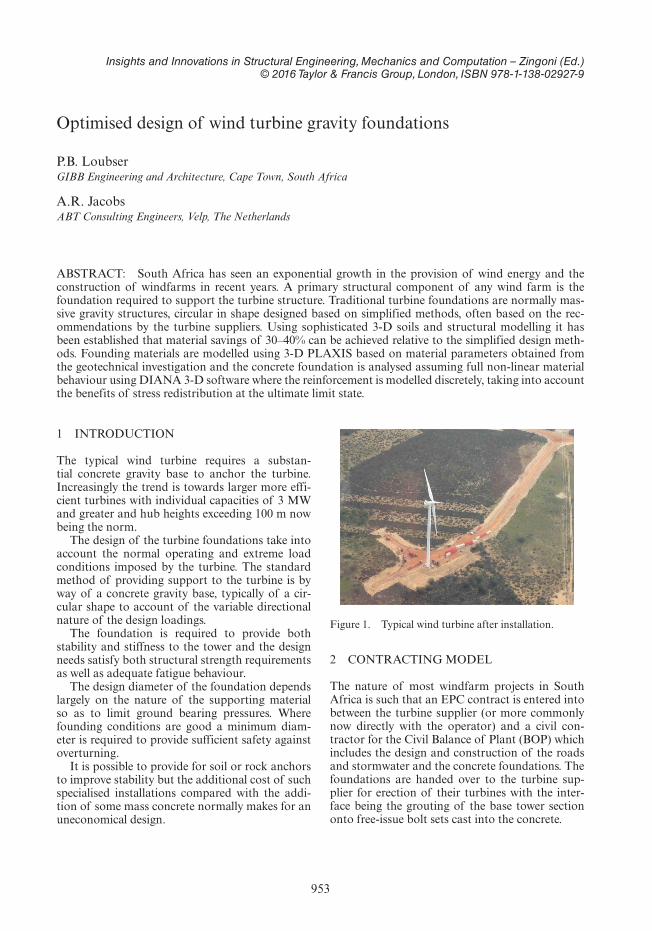
Figure 1. Typical wind turbine after installation.
954
The ePC contractor therefore takes full respon-sibility for the foundation design and has the opportunity to optimise such design to the overall benefit of the project. Typically the Civil BOP can comprise up to 10% of the total development cost of the windfarm so although a small component overall savings can still be significant.
There are however frequently significant and often onerous specification and design conditions imposed by both the turbine supplier and the oper-ator which can negatively affect the design opti-misation process. Unfortunately there seem to be enough incidences of failure of turbines worldwide which has led to some operators becoming risk averse and insisting on very conservative design assumptions.
3 STRUCTURAL FORM
Typical foundation diameters vary from as little as 15 m to as much as 20 m where soil conditions are poor. Although various turbine suppliers have their own proprietary details which vary slightly, the turbine towers are generally fixed to the con-crete foundation by way of cast-in high tensile bolts which are stressed after installation.
The required thickness of the concrete founda-tion under the tower is controlled by both struc-tural requirements as well as the embedment requirements for the bolts, resulting in thicknesses in excess of 2.5 m to 3.0 m.
The structural element acts primarily as a canti-lever from the central support pedestal which allows for the thickness to be reduced towards the outer edge of the foundations. Typically the edge thick-ness can be as low as 0.4 m however steep slopes make for more difficulty in casting where a back shutter is not provided for. The circular nature of the base also makes for relatively simple formwork
where the outer steel shutter is effectively in ring tension.
Typically the concrete volumes involved are any-where between 350 and 450 m3 and the large forces involved require reinforcing densities anywhere between 80 and 100 kg/m3 depending on the design philosophy employed.
The nature of the design is such that there is a relatively high congestion of rebar at the centre of the foundation and the rebar detailing needs to take this into account, together with the need to allow passage of the ducting required for installa-tion of power cables from the turbine.
4 DeSIgN CODeS
As most of the wind turbine manufacturers are located in europe, in general eurocode standards and codes are applied for the foundation design, although reference is also made to the incorpo-ration of local code requirements to suit local conditions.
Typical designs are carried out to the following codes
• eurocode 2 for concrete design• eurocode 7 for geotechnical design• CeB FIP model code 2010 for fatigue checks
In addition certain turbine manufacturers may also make reference to other codes such as germa-nischer Lloyd or DNV for example.
5 DeSIgN PROCeSS AND ASSeSSMeNT OF The RISk OF FAILURe
The design loadings as applied to the foundations, both static and fatigue, are normally provided by the turbine supplier specific for a particular tur-bine, and assume minimum foundation rotational and lateral stiffnesses for the loadings to be valid.
Often design guidelines are also given which are based on very simplified linear elastic assumptions.
Advances in computer modelling and design are such that significant economies can be gained through the use of full 3-D modelling both for soil modelling as well as for the reinforced concrete design.
The large number of repetitions within a windfarm, often with adjacent windfarms being designed for the same basic loading criteria and similar ground conditions, lends itself to investing much more effort in the design phase of the project so as to ensure optimisation of the design with associated material and program savings.
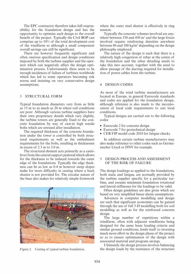
Ultimately the design process involves balancing the design loads by the resistance of the structure Figure 2. Casting of typical turbine foundation.
955
with an adequate degree of safety in accordance with established design codes. The loads for the design are defined with a high degree of accuracy however the resistance of the structure is relatively poorly defined due to a number of factors:
• high sensitivity to geotechnical conditions• Bearing pressures• Rotational and lateral stiffness• Settlements
• Structural response of reinforced concrete base
The foundation design process involves two rela-tively independent but related design processes viz. the behaviour and capacity of the soil in response to the structural loading, and the subsequent design of the concrete element that comprises the base and transfers the loadings from the tower to the soil.
5.1 Geotechnical design
The following aspects control the design and gen-erally dictate the size and form of the base:
• Bearing capacity of the founding material• Rotational stiffness• Allowable settlements• FOS against overturning• gapping (% of base width subject to tension)
The controlling criteria will depend on the nature of the founding material. For good qual-ity founding the requirement for limiting gapping and overturning stability will control, whereas for poorer soils bearing capacity or rotational stiffness will be more significant. A gapping criterion inde-pendent from the soil type and properties, which is often used, can be argued. Soil degradation and therefore loss of stiffness and differential settle-ment should rather be judged using other criteria than gapping.
The effects of uplift by groundwater on the foundation size can be substantial. A detailed estimation of the probability of high water levels, caused by high groundwater levels or rain water accumulation, is therefore essential.
5.2 Structural design
The design of the reinforced concrete structural element takes into account the following design aspects:
• Moment capacity• Shear capacity• Crack control• Anchor bolt anchorage• Anchor bolt prestress splitting• Fatigue
The structural design process involves the appli-cation of the defined loadings with the various load factors onto a model of the structure with some realistic representation of the soils support.
6 OPTIMISATION AND LeVeLS OF APPROXIMATION
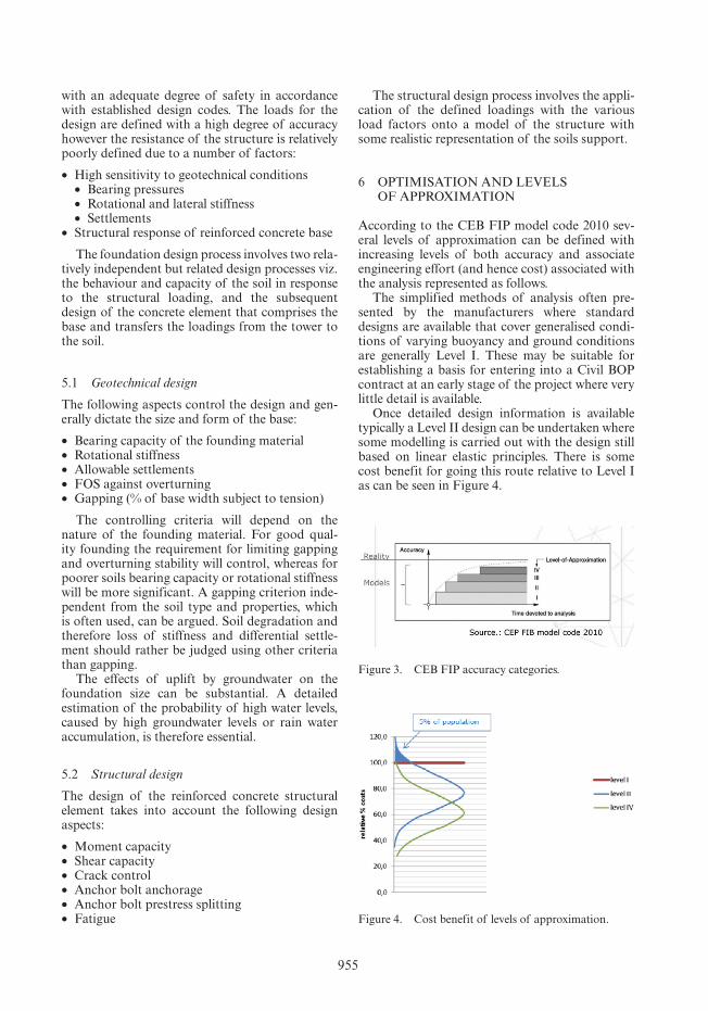
According to the CeB FIP model code 2010 sev-eral levels of approximation can be defined with increasing levels of both accuracy and associate engineering effort (and hence cost) associated with the analysis represented as follows.
The simplified methods of analysis often pre-sented by the manufacturers where standard designs are available that cover generalised condi-tions of varying buoyancy and ground conditions are generally Level I. These may be suitable for establishing a basis for entering into a Civil BOP contract at an early stage of the project where very little detail is available.
Once detailed design information is available typically a Level II design can be undertaken where some modelling is carried out with the design still based on linear elastic principles. There is some cost benefit for going this route relative to Level I as can be seen in Figure 4.
Figure 3. CeB FIP accuracy categories.
Figure 4. Cost benefit of levels of approximation.
956
The most significant savings are achieved when progressing to a Level IV approximation, which in this instance represents a full non-linear analysis where the actual behaviour of the structure under loading is modelled accurately using sophisticated software which incorporates realistic material behaviour.
7 LINeAR eLASTIC DeSIgN ANALySIS (LeVeL II)
Linear elastic design assumes that under all load-ing conditions, the materials (concrete and rebar) remain elastic. Typically the assessment of the founding material is done by way of simplified bearing capacity formulae and the support pro-vided to the foundation is modelled by way of dis-crete spring stiffnesses.
The concrete structure can be modelled in vari-ous ways with the preference being to use some type of 3-D finite element model to try and rep-resent the circular base as realistically as possible. Typically the model is assumed to have linear elas-tic elements and the resulting elastic stresses are converted into global moments and shears by way of Wood Armor or some other method. It is not common to include the modelling of rebar dis-cretely when carrying out this analysis.
Localised stresses associated with highly stressed areas around the anchor bolts and tower base can be modelled separately but more generally simpli-fying assumptions are made to provide rebar to account for any bursting stresses.
A more realistic 3-D modelling of the founding materials by way of PLAXIS 3-D or similar can be used to provide additional accuracy with regard to this aspect of the design but frequently the con-trolling factors tend to be gapping and overturn-ing rather than any bearing capacity of rotational stiffness issues.
8 NON-LINeAR DeSIgN (LeVeL IV)
8.1 Modelling
The non-linear design process involves a very simi-lar process to the linear elastic analysis and design but has some very specific differences. It needs to be emphasised here that although there is obvi-ously computer software available that is specifi-cally tailored to non-linear modelling this is not an area that many engineers specialise in and caution needs to be taken to make sure that the analysis and design is undertaken by experienced and spe-cialised engineers familiar with both the method and the software.
Currently the option of a full 3-D model of com-bined soil-structure is not possible as the size of the model and the computational power required is prohibitive.
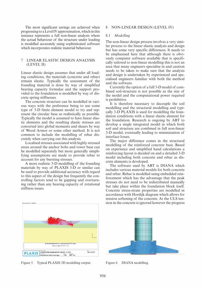
It is therefore necessary to decouple the soil modelling and the structural modelling and typi-cally 3-D PLAXIS is used for modelling the foun-dation conditions with a linear elastic element for the foundation. Research is ongoing by ABT to develop a single integrated model in which both soil and structure are combined in full non-linear 3-D model, eventually leading to minimization of interface losses.
The major difference comes in the structural modelling of the reinforced concrete base. Based on experience and simplified hand calculations a reinforcing layout is decided on and a detailed 3-D model including both concrete and rebar as dis-crete elements is developed.
The software used by ABT is DIANA which includes various material models for both concrete and rebar. Rebar is modelled using embedded rein-forcement which has the advantage that the peak stresses do not need to be redistributed manually but take place within the foundation block itself. Concrete stress-strain properties are modelled in accordance with hordijk diagram which allows for tension softening of the concrete. At the ULS ten-sion in the concrete is ignored however the progress
Figure 5. Typical PLAXIS 3D modelling output. Figure 6. DIANA modelling.
957
of tensile strength is required to take up the shear forces developed.
Stresses and strain in the compressive zone of the concrete are assumed to develop according to a non-linear parabolic diagram in accordance with eN-1992-1-1 whilst the stress-strain diagram for the rebar is also as defined as per eN-1992-1-1 with a maximum loading strain of 0.0045.
Anchor bars may be discretely modelled and the grout between the tower section and the base can be modelled by means of interface elements. This is important as it allows for an accurate assessment
of this highly stressed area which is very sensitive to fatigue loading.
8.2 Evaluation of output
As with any analysis and design process it is critical that the results be assessed by an engineer experi-ence in working with such model to ensure that the results are valid.
In addition to the normal output of concrete and rebar stresses at various load levels it is also possible to get detailed estimates of crack pat-terns as well as strains and associated non-linear displacements.
9 ReSULTS OF COMPARATIVe ASSeSSMeNT
Although optimised design solutions had already been implemented on a number of successful windfarm projects using non-linear modelling, on a recent project the operator was not prepared to accept the results of this non-linear method of analysis and insisted on a re-design based on linear elastic methods, despite the significant impact the design had on the overall cost.
Although obviously very frustrating, the result-ing exercise allowed the project team to get a very specific comparison of the results of the two design methods as described below.
The specialist design of the foundations was carried out by ABT Consulting engineers of hol-land who have a long history of work in the wind energy generation business.
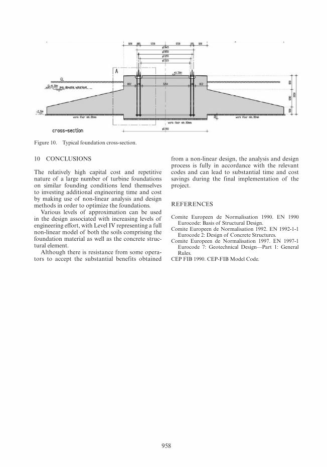
The typical form of the foundation assumed is as shown in Figure 10 based on a typical Vestas anchoring requirement and provision for cable exit below blinding level.
The resulting output from the comparison was as follows:
Analysis type Linear elastic Non-linear Saving
Approximation Level II Level IVBase diameter 16.2 m 15.5 mConcrete volume 256.6 m3 239.7 m3 7.1%Rebar 23.5 t 17.5 t 34.3%
The relatively low level of the saving in concrete is attributed to the fact that for this windfarm site the founding material was extremely good and the base sizing was controlled more by gapping crite-ria rather than foundation bearing capacity. Also 3-D PLAXIS was used for both analyses so there is already an element of approximation in the found-ing design better than Level II for the linear elastic design.
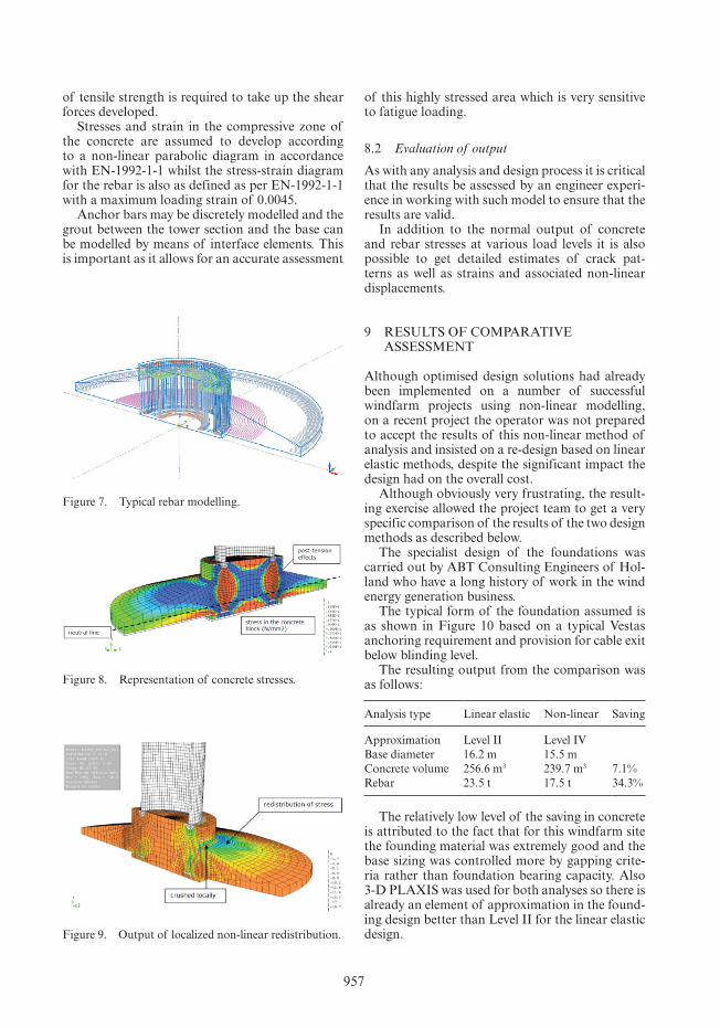
Figure 7. Typical rebar modelling.
Figure 8. Representation of concrete stresses.
Figure 9. Output of localized non-linear redistribution.
958
10 CONCLUSIONS
The relatively high capital cost and repetitive nature of a large number of turbine foundations on similar founding conditions lend themselves to investing additional engineering time and cost by making use of non-linear analysis and design methods in order to optimize the foundations.
Various levels of approximation can be used in the design associated with increasing levels of engineering effort, with Level IV representing a full non-linear model of both the soils comprising the foundation material as well as the concrete struc-tural element.
Although there is resistance from some opera-tors to accept the substantial benefits obtained
Figure 10. Typical foundation cross-section.
from a non-linear design, the analysis and design process is fully in accordance with the relevant codes and can lead to substantial time and cost savings during the final implementation of the project.
ReFeReNCeS
Comite europeen de Normalisation 1990. eN 1990 eurocode: Basis of Structural Design.
Comite europeen de Normalisation 1992. eN 1992-1-1 eurocode 2: Design of Concrete Structures.
Comite europeen de Normalisation 1997. eN 1997-1 eurocode 7: geotechnical Design—Part 1: general Rules.
CeP FIB 1990. CeP-FIB Model Code.