Embed Size (px)
Citation preview
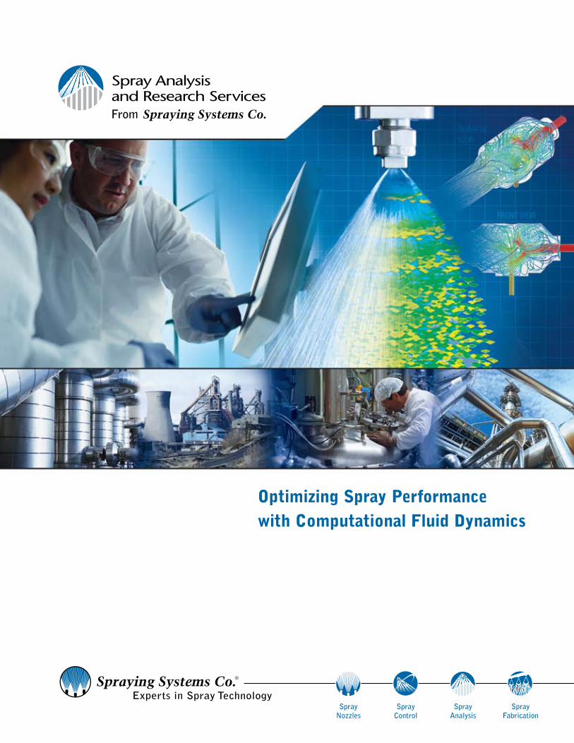
Optimizing Spray Performance with Computational Fluid Dynamics
From Spraying Systems Co.
Spray Nozzles
Spray Control
Spray Analysis
Spray Fabrication
2From Spraying Systems Co.
www.sprayconsultants.com
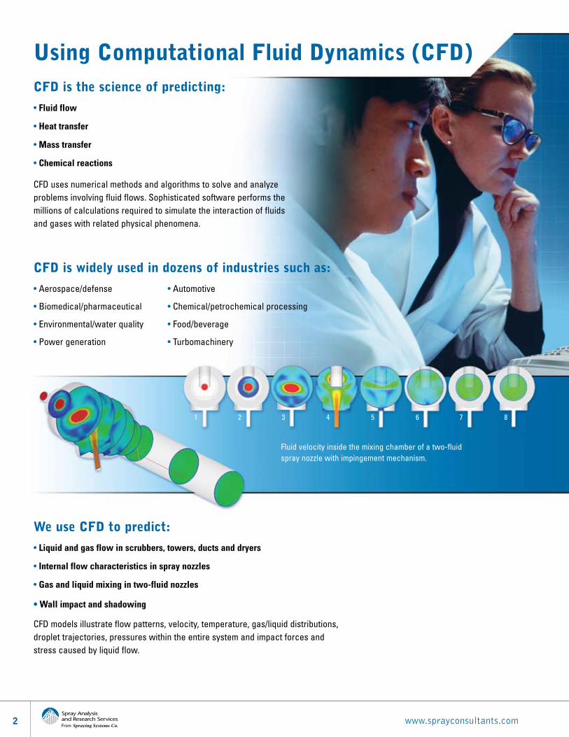
Using Computational Fluid Dynamics (CFD)CFD is the science of predicting:
• Fluid flow
• Heat transfer
• Mass transfer
• Chemical reactions
CFD uses numerical methods and algorithms to solve and analyze problems involving fluid flows. Sophisticated software performs the millions of calculations required to simulate the interaction of fluids and gases with related physical phenomena.
CFD is widely used in dozens of industries such as:
• Aerospace/defense • Automotive
• Biomedical/pharmaceutical • Chemical/petrochemical processing
• Environmental/water quality • Food/beverage
• Power generation • Turbomachinery
We use CFD to predict:
• Liquid and gas flow in scrubbers, towers, ducts and dryers
• Internal flow characteristics in spray nozzles
• Gas and liquid mixing in two-fluid nozzles
• Wall impact and shadowing
CFD models illustrate flow patterns, velocity, temperature, gas/liquid distributions, droplet trajectories, pressures within the entire system and impact forces and stress caused by liquid flow.
Fluid velocity inside the mixing chamber of a two-fluid spray nozzle with impingement mechanism.
1 2 3 4 5 6 7 8
31.800.95.SPRAY | Intl. 1.630.665.5000 | www.spray.comFrom Spraying Systems Co.
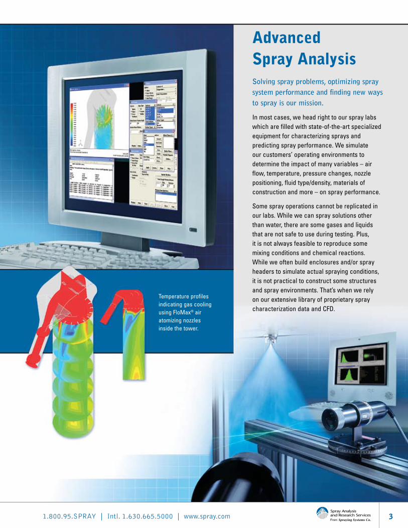
Advanced Spray Analysis Solving spray problems, optimizing spray system performance and finding new ways to spray is our mission.
In most cases, we head right to our spray labs which are filled with state-of-the-art specialized equipment for characterizing sprays and predicting spray performance. We simulate our customers’ operating environments to determine the impact of many variables – air flow, temperature, pressure changes, nozzle positioning, fluid type/density, materials of construction and more – on spray performance.
Some spray operations cannot be replicated in our labs. While we can spray solutions other than water, there are some gases and liquids that are not safe to use during testing. Plus, it is not always feasible to reproduce some mixing conditions and chemical reactions. While we often build enclosures and/or spray headers to simulate actual spraying conditions, it is not practical to construct some structures and spray environments. That’s when we rely on our extensive library of proprietary spray characterization data and CFD.
Temperature profiles indicating gas cooling using FloMax® air atomizing nozzles inside the tower.
4From Spraying Systems Co.
www.sprayconsultants.com
How Our Approach to CFD is Different… And Yields Better Results The difference between standard and custom CFD
Standard CFD models use theoretical numeric codes that require extensive user time commitments and computational resources. Users must compile and prepare a wide variety of specific information – often requiring weeks of work. Once the data is input into the CFD modeling program, the computational work begins. The computation time will be dependent on the complexity of the model. Standard desktop computers can be used, however, computations can take weeks to complete.
Our custom CFD models use data we’ve collected in our spray labs and considerably shorten the amount of time required for data preparation and entry. We can often complete the preparation phase in a matter of days rather than weeks. Computation time is also reduced significantly due to the specially equipped hardware we use. Although each model is different, one recent project was completed in less than an hour compared to the nearly two days required prior to our latest hardware upgrade. This shortened the overall project time to weeks rather than months.
The use of actual spray performance data increases model accuracy
Using estimated data increases the error factor in CFD modeling. For example, theoretical calculation of coverage overestimates the real spray coverage and cannot account for specific conditions that may impact the spray such as co- or counter-current gas flow, heat barriers and more. In addition, our research has shown that the error factor in theoretical calculations increases as the distance from the nozzle to the target increases.
Our CFD modeling of sprays uses actual drop size and velocity data we’ve collected in our labs. We use this extensive database of performance data in every model where drop size and velocity play a role in the physical process. Our experienced engineers, specialists in spray technology, understand when to rely on our proprietary data or conduct additional testing in the lab to ensure the required level of accuracy.
51.800.95.SPRAY | Intl. 1.630.665.5000 | www.spray.comFrom Spraying Systems Co.
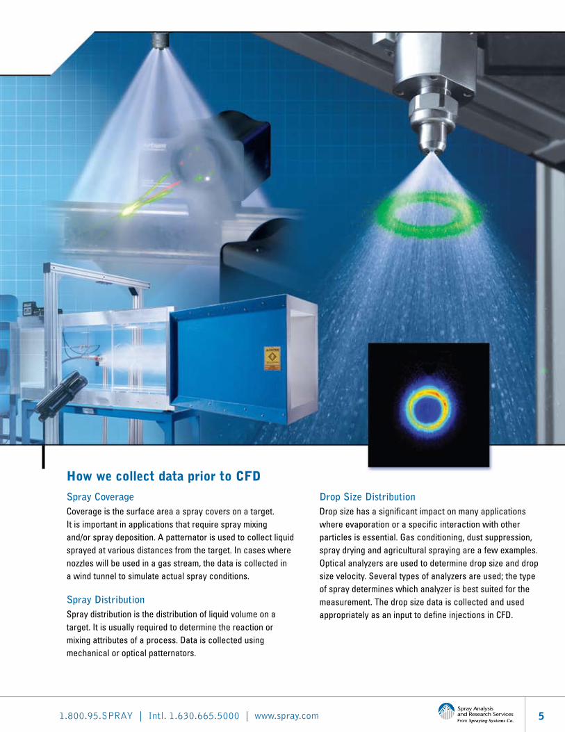
How we collect data prior to CFD
Spray CoverageCoverage is the surface area a spray covers on a target. It is important in applications that require spray mixing and/or spray deposition. A patternator is used to collect liquid sprayed at various distances from the target. In cases where nozzles will be used in a gas stream, the data is collected in a wind tunnel to simulate actual spray conditions.
Spray DistributionSpray distribution is the distribution of liquid volume on a target. It is usually required to determine the reaction or mixing attributes of a process. Data is collected using mechanical or optical patternators.
Drop Size DistributionDrop size has a significant impact on many applications where evaporation or a specific interaction with other particles is essential. Gas conditioning, dust suppression, spray drying and agricultural spraying are a few examples. Optical analyzers are used to determine drop size and drop size velocity. Several types of analyzers are used; the type of spray determines which analyzer is best suited for the measurement. The drop size data is collected and used appropriately as an input to define injections in CFD.
6From Spraying Systems Co.
www.sprayconsultants.com
Problem-Solving with CFD
Gas conditioning in a cooling tower
CASe StuDy:
Challenge:
A major refinery needed to upgrade a gas conditioning tower to comply with government environmental standards. There were many obstructions and sharp bends throughout the tower that could negatively impact spray nozzle performance, result in wall wetting and preclude effective cooling.
Requirements:
5:1 turndown ratio
Operate in an atomizing steam pressure range below 100 psi (7 bar) and a water injection pressure in the range of the atomizing pressure
Tight drop size distribution in the exhaust gas flow
Low spray trajectory that would insure no wall wetting
The sprayed liquid must evaporate before the exit of the duct to avoid any damage to downstream equipment
Large free passage nozzle to reduce clogging
Solution:
We designed the cooling system for the tower based on customer requirements using our FloMax® gas atomizing nozzles. We were then asked to validate the design.
Using CFD and actual FloMax nozzle performance data collected in our labs, we determined that the proposed design would result in wall wetting, hot spots on sidewalls causing damage to wall lining and ultimate system failure.
We developed an alternate design that eliminated the sidewall hot spots and improved evaporation by 10%.
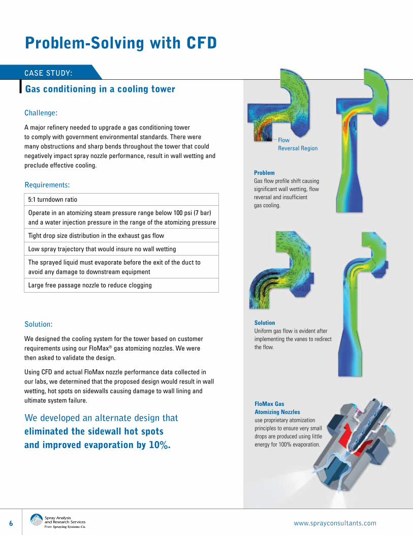
Problem Gas flow profile shift causing significant wall wetting, flow reversal and insufficient gas cooling.
FloMax Gas Atomizing Nozzles use proprietary atomization principles to ensure very small drops are produced using little energy for 100% evaporation.
Solution Uniform gas flow is evident after implementing the vanes to redirect the flow.
Flow Reversal Region
71.800.95.SPRAY | Intl. 1.630.665.5000 | www.spray.comFrom Spraying Systems Co.
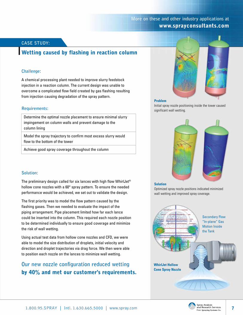
Challenge:
A chemical processing plant needed to improve slurry feedstock injection in a reaction column. The current design was unable to overcome a complicated flow field created by gas flashing resulting from injection causing degradation of the spray pattern.
Requirements:
Determine the optimal nozzle placement to ensure minimal slurry impingement on column walls and prevent damage to the column lining
Model the spray trajectory to confirm most excess slurry would flow to the bottom of the tower
Achieve good spray coverage throughout the column
Solution:
The preliminary design called for six lances with high flow WhirlJet® hollow cone nozzles with a 60° spray pattern. To ensure the needed performance would be achieved, we set out to validate the design.
The first priority was to model the flow pattern caused by the flashing gases. Then we needed to evaluate the impact of the piping arrangement. Pipe placement limited how far each lance could be inserted into the column. This required each nozzle position to be determined individually to ensure good coverage and minimize the risk of wall wetting.
Using actual test data from hollow cone nozzles and CFD, we were able to model the size distribution of droplets, initial velocity and direction and droplet trajectories via drag force. We then were able to position each nozzle on the lances to minimize wall wetting.
Our new nozzle configuration reduced wetting by 40% and met our customer’s requirements.
Wetting caused by flashing in reaction column
CASe StuDy:
WhirlJet Hollow Cone Spray Nozzle
Problem Initial spray nozzle positioning inside the tower caused significant wall wetting.
Solution Optimized spray nozzle positions indicated minimized wall wetting and improved spray coverage.
More on these and other industry applications at www.sprayconsultants.com
Secondary Flow “In-plane” Gas Motion Inside the Tank
Other Helpful Resources
Spray Analysis and Research Services Bulletin 520C
8-page bulletin addresses how advanced spray testing helps determine performance under varying operating conditions to ensure application success.
Spray Technology Reference Guide: Understanding Drop Size Bulletin 459C
36-page educational guide takes an in-depth look at atomization, drop size measurement techniques, analyzers, data collection and analysis and more.
Optimizing Your Spray System Technical Manual 410
52-page handbook explains how to evaluate your spray system, uncover and solve costly problems, improve quality, reduce maintenance time and more.
A Guide to Spray Technology for Pharmaceutical Processing Bulletin 599A
6-page bulletin covers spray nozzles for tablet coating, tank washing and spray drying.
Improving Process and Product Quality in Chemical Production Through Spray Technology Bulletin 568
12-page bulletin provides an overview of how spray technology is used in a wide range of applications.
Gas Cooling and Conditioning Guide Bulletin 540B
12-page bulletin describes how to optimize efficiency and performance in gas cooling and conditioning applications.
North Avenue and Schmale Road, P.O. Box 7900, Wheaton, IL 60187-7901 USA
Tel: 1.800.95.SPRAY Intl. Tel: 1.630.665.5000 Fax: 1.888.95.SPRAY Intl. Fax: 1.630.260.0842
www.spray.com
Bulletin No. 621A Printed in the U.S.A. ©Spraying Systems Co. 2009
SprayNozzles
SprayControl
SprayAnalysis
SprayFabrication