Embed Size (px)
Citation preview
Journal of Engineering and Technology of The Open University of Sri Lanka (JET-OUSL), Vol. 1, No.1
1
Optimum Blasting Parameters for Single Shot Blasting in
Non Fractured Biotite-Gneiss Rocks of Sri Lanka
H.A.S.I Abeywardana1, G.G.K.Kodagoda1, M.N.C Samarawickrama2*
1Sri Lanka Air Force, Colombo, Sri Lanka
1Northshore College of Business & Technology (PVT) Ltd, Colombo 15, Sri Lanka 2*Department of Civil Engineering, Open University of Sri Lanka, Nawala, Nugegoda, Sri Lanka
*Corresponding Author email: [email protected] , Tele: +94112881479
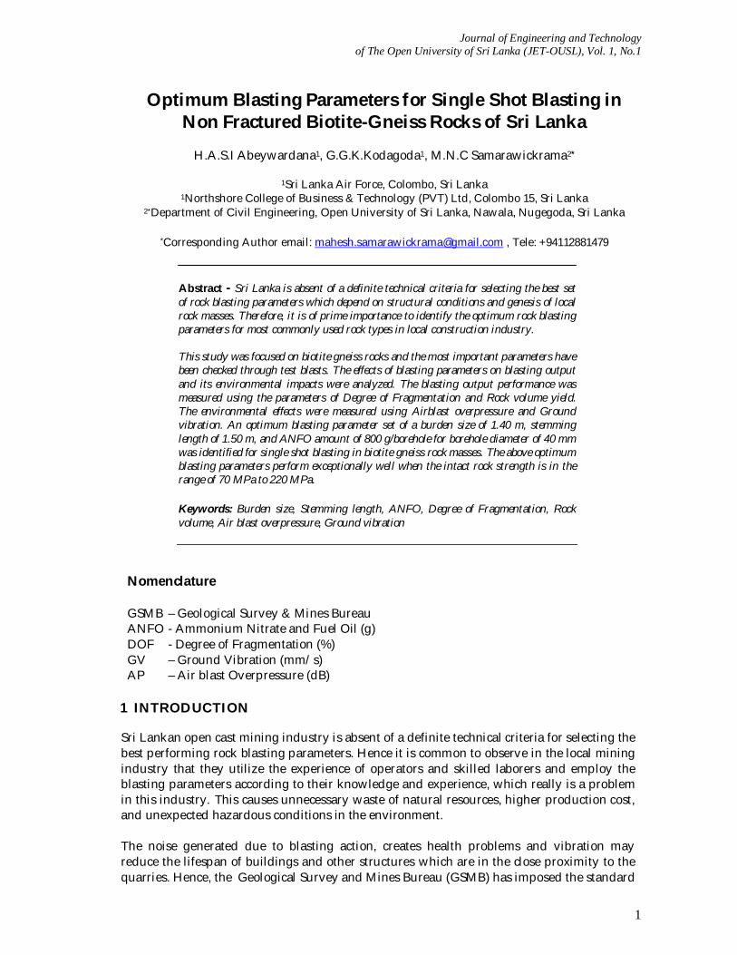
Abstract - Sri Lanka is absent of a definite technical criteria for selecting the best set of rock blasting parameters which depend on structural conditions and genesis of local rock masses. Therefore, it is of prime importance to identify the optimum rock blasting parameters for most commonly used rock types in local construction industry. This study was focused on biotite gneiss rocks and the most important parameters have been checked through test blasts. The effects of blasting parameters on blasting output and its environmental impacts were analyzed. The blasting output performance was measured using the parameters of Degree of Fragmentation and Rock volume yield. The environmental effects were measured using Airblast overpressure and Ground vibration. An optimum blasting parameter set of a burden size of 1.40 m, stemming length of 1.50 m, and ANFO amount of 800 g/borehole for borehole diameter of 40 mm was identified for single shot blasting in biotite gneiss rock masses. The above optimum blasting parameters perform exceptionally well when the intact rock strength is in the range of 70 MPa to 220 MPa. Keywords: Burden size, Stemming length, ANFO, Degree of Fragmentation, Rock volume, Air blast overpressure, Ground vibration
Nomenclature GSMB – Geological Survey & Mines Bureau ANFO - Ammonium Nitrate and Fuel Oil (g) DOF - Degree of Fragmentation (%) GV – Ground Vibration (mm/s) AP – Air blast Overpressure (dB)
1 INTRODUCTION
Sri Lankan open cast mining industry is absent of a definite technical criteria for selecting the best performing rock blasting parameters. Hence it is common to observe in the local mining industry that they utilize the experience of operators and skilled laborers and employ the blasting parameters according to their knowledge and experience, which really is a problem in this industry. This causes unnecessary waste of natural resources, higher production cost, and unexpected hazardous conditions in the environment. The noise generated due to blasting action, creates health problems and vibration may reduce the lifespan of buildings and other structures which are in the close proximity to the quarries. Hence, the Geological Survey and Mines Bureau (GSMB) has imposed the standard
Journal of Engineering and Technology of The Open University of Sri Lanka (JET-OUSL), Vol. 1, No.1
2
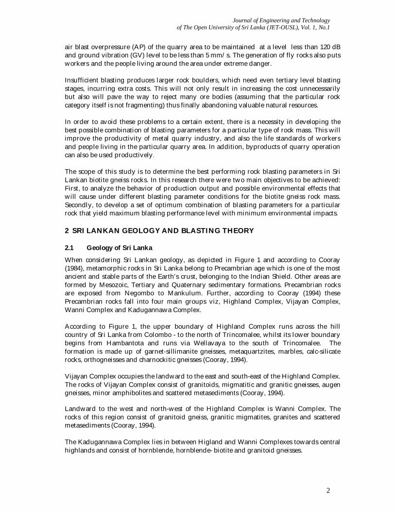
air blast overpressure (AP) of the quarry area to be maintained at a level less than 120 dB and ground vibration (GV) level to be less than 5 mm/s. The generation of fly rocks also puts workers and the people living around the area under extreme danger. Insufficient blasting produces larger rock boulders, which need even tertiary level blasting stages, incurring extra costs. This will not only result in increasing the cost unnecessarily but also will pave the way to reject many ore bodies (assuming that the particular rock category itself is not fragmenting) thus finally abandoning valuable natural resources. In order to avoid these problems to a certain extent, there is a necessity in developing the best possible combination of blasting parameters for a particular type of rock mass. This will improve the productivity of metal quarry industry, and also the life standards of workers and people living in the particular quarry area. In addition, byproducts of quarry operation can also be used productively. The scope of this study is to determine the best performing rock blasting parameters in Sri Lankan biotite gneiss rocks. In this research there were two main objectives to be achieved: First, to analyze the behavior of production output and possible environmental effects that will cause under different blasting parameter conditions for the biotite gneiss rock mass. Secondly, to develop a set of optimum combination of blasting parameters for a particular rock that yield maximum blasting performance level with minimum environmental impacts. 2 SRI LANKAN GEOLOGY AND BLASTING THEORY 2.1 Geology of Sri Lanka
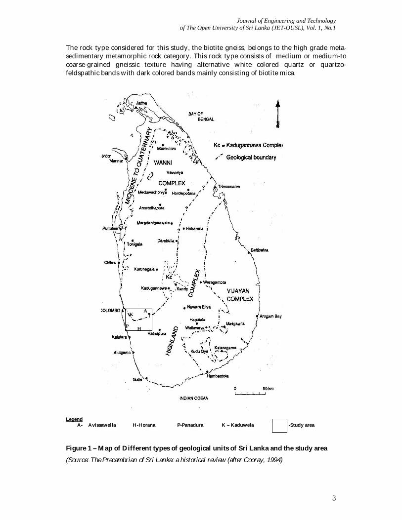
When considering Sri Lankan geology, as depicted in Figure 1 and according to Cooray (1984), metamorphic rocks in Sri Lanka belong to Precambrian age which is one of the most ancient and stable parts of the Earth’s crust, belonging to the Indian Shield. Other areas are formed by Mesozoic, Tertiary and Quaternary sedimentary formations. Precambrian rocks are exposed from Negombo to Mankulum. Further, according to Cooray (1994) these Precambrian rocks fall into four main groups viz, Highland Complex, Vijayan Complex, Wanni Complex and Kadugannawa Complex. According to Figure 1, the upper boundary of Highland Complex runs across the hill country of Sri Lanka from Colombo - to the north of Trincomalee, whilst its lower boundary begins from Hambantota and runs via Wellavaya to the south of Trincomalee. The formation is made up of garnet-sillimanite gneisses, metaquartzites, marbles, calc-silicate rocks, orthogneisses and charnockitic gneisses (Cooray, 1994). Vijayan Complex occupies the landward to the east and south-east of the Highland Complex. The rocks of Vijayan Complex consist of granitoids, migmatitic and granitic gneisses, augen gneisses, minor amphibolites and scattered metasediments (Cooray, 1994). Landward to the west and north-west of the Highland Complex is Wanni Complex. The rocks of this region consist of granitoid gneiss, granitic migmatites, granites and scattered metasediments (Cooray, 1994). The Kadugannawa Complex lies in between Higland and Wanni Complexes towards central highlands and consist of hornblende, hornblende- biotite and granitoid gneisses.
Journal of Engineering and Technology of The Open University of Sri Lanka (JET-OUSL), Vol. 1, No.1
3
The rock type considered for this study, the biotite gneiss, belongs to the high grade meta-sedimentary metamorphic rock category. This rock type consists of medium or medium-to coarse-grained gneissic texture having alternative white colored quartz or quartzo-feldspathic bands with dark colored bands mainly consisting of biotite mica. Legend
A- Avissawella H-Horana P-Panadura K – Kaduwela -Study area Figure 1 – Map of Different types of geological units of Sri Lanka and the study area
(Source: The Precambrian of Sri Lanka: a historical review (after Cooray, 1994)
P
H
A K
P
Journal of Engineering and Technology of The Open University of Sri Lanka (JET-OUSL), Vol. 1, No.1
4
2.2 Theory of Rock Blasting
There are a number of theories to explain how rocks are fragmented by explosives. Most popular of them is the reflection theory. When detonating occurs, explosive charge creates a high gas pressure in the blast hole. This generates a compressive strain pulse in the surrounding rock and travels outward in all directions from the center of the hole. Strain pulse decays rapidly with the crushing of the rock in the vicinity of the blast hole. When original compressive strain pulse reaches free surface, reflection tensile strain pulse will generate. The bulk of the rock mass is progressively broken up away from the free faces. To break the massive rocks, higher blast hole pressure should be provided. Therefore selected explosives should be of maximum strength and detonation velocity. When highly stratified or fissured rocks have to be blasted, the total area of discontinuities is relatively larger than that is created by the blasting. Therefore the explosives of low density and detonation velocity are more efficient. When the detonation of an explosive creates too many fines during the effect of crushing of the rock, it should use Ammonium Nitrate (NH4NO3) + Fuel Oil (CH2) (commonly called as ANFO) mixture and the mixtures of ANFO with inert substances (Carcedo et al., 1995). In Sri Lanka, the mix proportion is 94% of NH4NO3 and 6% of CH2 by weight. The quantity of explosives necessary to fragment 1 m³ of rock is known as the powder factor. One Kilogram of explosive can expand to 1,000 litres of gas in milliseconds and released up to 5,000 kJ of heat. 3NH4NO3 + CH2 → 7H2O + 3N2 + CO2 + Heat 2.3 Common Rock Blasting Parameters
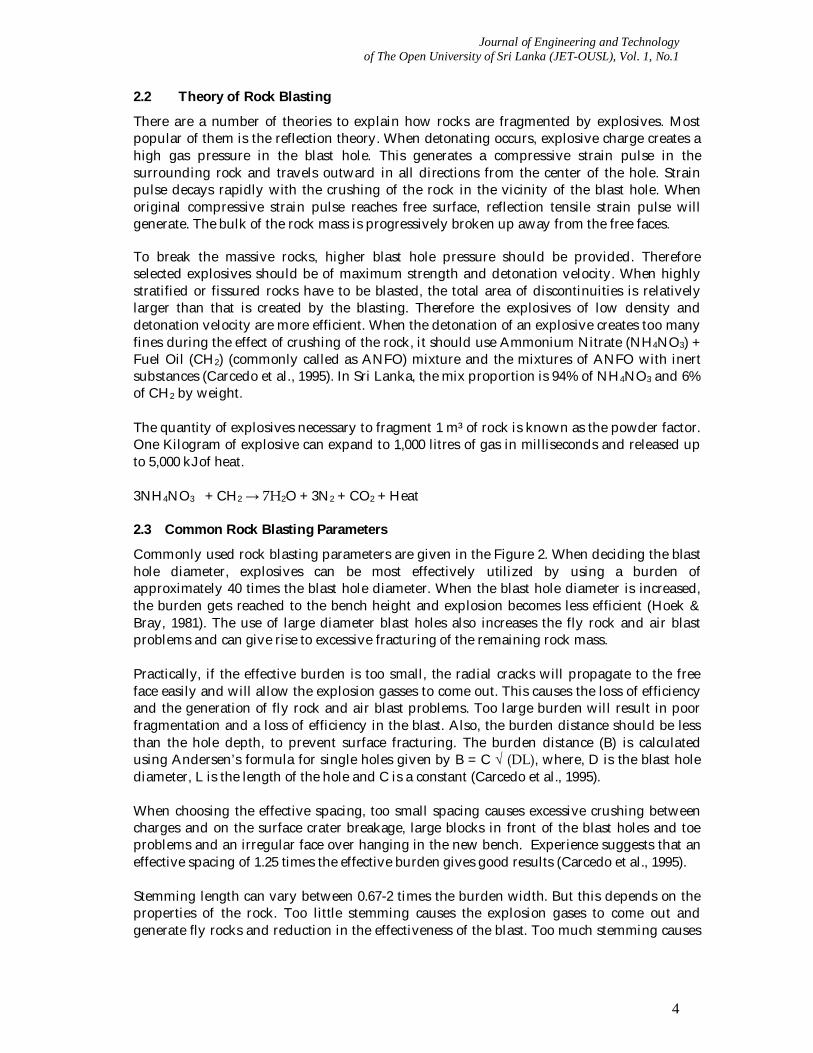
Commonly used rock blasting parameters are given in the Figure 2. When deciding the blast hole diameter, explosives can be most effectively utilized by using a burden of approximately 40 times the blast hole diameter. When the blast hole diameter is increased, the burden gets reached to the bench height and explosion becomes less efficient (Hoek & Bray, 1981). The use of large diameter blast holes also increases the fly rock and air blast problems and can give rise to excessive fracturing of the remaining rock mass. Practically, if the effective burden is too small, the radial cracks will propagate to the free face easily and will allow the explosion gasses to come out. This causes the loss of efficiency and the generation of fly rock and air blast problems. Too large burden will result in poor fragmentation and a loss of efficiency in the blast. Also, the burden distance should be less than the hole depth, to prevent surface fracturing. The burden distance (B) is calculated using Andersen’s formula for single holes given by B = C √ (DL), where, D is the blast hole diameter, L is the length of the hole and C is a constant (Carcedo et al., 1995). When choosing the effective spacing, too small spacing causes excessive crushing between charges and on the surface crater breakage, large blocks in front of the blast holes and toe problems and an irregular face over hanging in the new bench. Experience suggests that an effective spacing of 1.25 times the effective burden gives good results (Carcedo et al., 1995). Stemming length can vary between 0.67-2 times the burden width. But this depends on the properties of the rock. Too little stemming causes the explosion gases to come out and generate fly rocks and reduction in the effectiveness of the blast. Too much stemming causes
Journal of Engineering and Technology of The Open University of Sri Lanka (JET-OUSL), Vol. 1, No.1
5
poor fragmentation of the rock above the top load. Stemming columns shorter than two thirds of the burden width, normally causes fly rock and back break problem (Carcedo et al., 1995).
Figure 2 - Definition of bench blasting terms Sub drilling or drilling to a depth below the toe of the bench is in order to break the rock on the floor of the bench, so that a shovel can dig into the required level. If there is poor fragmentation at this level, it can lead to very expensive shovel operations which cause delays and break downs. Excessive fragmentation shows that the rock forming the lower bench is damaged and will reduce its stability. Experience has shown that a Sub drilling depth of 0.2 to 0.3 times the distance between adjacent blast holes is usually adequate to ensure effective digging to bench grade (Carcedo et al., 1995). 2.4 Fragmentation of Rocks
When a solid mass of rock is broken by explosives, the size of distribution of rock boulders and particles produced are termed as Fragmentation. When poor fragmentation occurs, it needs secondary blasting operation to reduce the over size or large boulders. Then it can be handled economically, safely and efficiently by loading and haulage equipment. Excessive fragmentation of rock mass indicates possible wastage of explosives. In order to improve the fragmentation, measures such as reduction of hole depth. ( shallow holes with improved distribution of explosives), reduction of spacing between adjacent holes in a row, reduction of burden distance, use of an explosive with greater gas generation (have) and less brisance and using short delay detonators can be adopted.
Sub-drill depth
Burden Blast hole
Spacing
Stemming
Bench Height
Bottom load
Top load
Journal of Engineering and Technology of The Open University of Sri Lanka (JET-OUSL), Vol. 1, No.1
6
3 METHODOLOGY In this study, twenty (20) number of test blasts were carried out under the guidance of GSMB in the selected area. 3.1 Selection of the Study Area and Rock type
When analyzing the total rock aggregate consumption of Sri Lanka, the highest level of rock aggregate demand is in Western province. Considering this fact and the type of rock focused in this study, the quarrying operations are presently carried out in the Biotite gneissic rocks in Kaduwela, Panadura, Horana and Avissawella areas. Therefore, this study was restricted to the quarries located in the above areas. These locations are shown in the above Figure (figure 1) and as depicted in the map, geologically these belong to both Highland and Wanni Complexes and are located close to the boundary which separate these two Complexes. 3.2 General Assumptions Made
When going through the theory of rock blasting and structural properties of rocks it is quite a Complex task in developing a generalized combination of best performing blasting parameters suitable for every rock mass and for each and every blasting parameter. Therefore this study was conducted and results were analyzed while keeping following blasting parameter factors constant. 1. Blast hole Diameter is 40mm and the packing factor is equal to 1. 2. Sub-drill depth is zero. 3. Blast hole inclination is vertical. 4. No effective spacing between holes since the test blasts were carried out for single shot
holes only. 5. Rock mass is absent of fractures and the spacing between fracture planes is high. 6. Fly rock condition is absent. 3.3 Rock Blasting Parameter Measurements
Throughout the study, the performances (production performance) of test blasts were measured under different blasting parameter conditions (burden size (m), stemming length (m) and amount of explosives used (ANFO) (g)) and intact rock conditions (UCS value in MPa). 3.4 Production Performance Measurements
Keeping the above parameters constant, the performance of each test blast was analyzed in two folded criteria, viz., production performance and environmental impact performance. The production performance was measured using; Volume of rock yield (m3) and Degree of Fragmentation (%). The rock volume produced after each test blast was measured by tightly packing the aggregates on a flat area in a cubical arrangement. The plan area dimensions of this arrangement were always maintained as 4.0 m X 2.0 m. The degree of fragmentation (DOF) was measured using following Equation; DOF = Total Volume Yield due to blasting (m3) – Total Volume of rock boulders
which does have dimensions greater than 0.61 m (m3) X 100 (%) Total Volume Yield due to blasting (m3)
Journal of Engineering and Technology of The Open University of Sri Lanka (JET-OUSL), Vol. 1, No.1
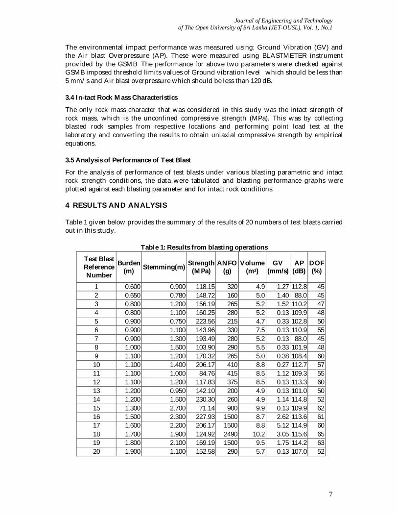
7
The environmental impact performance was measured using; Ground Vibration (GV) and the Air blast Overpressure (AP). These were measured using BLASTMETER instrument provided by the GSMB. The performance for above two parameters were checked against GSMB imposed threshold limits values of Ground vibration level which should be less than 5 mm/s and Air blast overpressure which should be less than 120 dB. 3.4 In-tact Rock Mass Characteristics
The only rock mass character that was considered in this study was the intact strength of rock mass, which is the unconfined compressive strength (MPa). This was by collecting blasted rock samples from respective locations and performing point load test at the laboratory and converting the results to obtain uniaxial compressive strength by empirical equations. 3.5 Analysis of Performance of Test Blast
For the analysis of performance of test blasts under various blasting parametric and intact rock strength conditions, the data were tabulated and blasting performance graphs were plotted against each blasting parameter and for intact rock conditions. 4 RESULTS AND ANALYSIS Table 1 given below provides the summary of the results of 20 numbers of test blasts carried out in this study.
Table 1: Results from blasting operations
Test Blast Reference Number
Burden (m) Stemming(m) Strength
(MPa) ANFO
(g) Volume
(m3) GV
(mm/s) AP
(dB) DOF (%)
1 0.600 0.900 118.15 320 4.9 1.27 112.8 45 2 0.650 0.780 148.72 160 5.0 1.40 88.0 45 3 0.800 1.200 156.19 265 5.2 1.52 110.2 47 4 0.800 1.100 160.25 280 5.2 0.13 109.9 48 5 0.900 0.750 223.56 215 4.7 0.33 102.8 50 6 0.900 1.100 143.96 330 7.5 0.13 110.9 55 7 0.900 1.300 193.49 280 5.2 0.13 88.0 45 8 1.000 1.500 103.90 290 5.5 0.33 101.9 48 9 1.100 1.200 170.32 265 5.0 0.38 108.4 60 10 1.100 1.400 206.17 410 8.8 0.27 112.7 57 11 1.100 1.000 84.76 415 8.5 1.12 109.3 55 12 1.100 1.200 117.83 375 8.5 0.13 113.3 60 13 1.200 0.950 142.10 200 4.9 0.13 101.0 50 14 1.200 1.500 230.30 260 4.9 1.14 114.8 52 15 1.300 2.700 71.14 900 9.9 0.13 109.9 62 16 1.500 2.300 227.93 1500 8.7 2.62 113.6 61 17 1.600 2.200 206.17 1500 8.8 5.12 114.9 60 18 1.700 1.900 124.92 2490 10.2 3.05 115.6 65 19 1.800 2.100 169.19 1500 9.5 1.75 114.2 63 20 1.900 1.100 152.58 290 5.7 0.13 107.0 52
Journal of Engineering and Technology of The Open University of Sri Lanka (JET-OUSL), Vol. 1, No.1
8
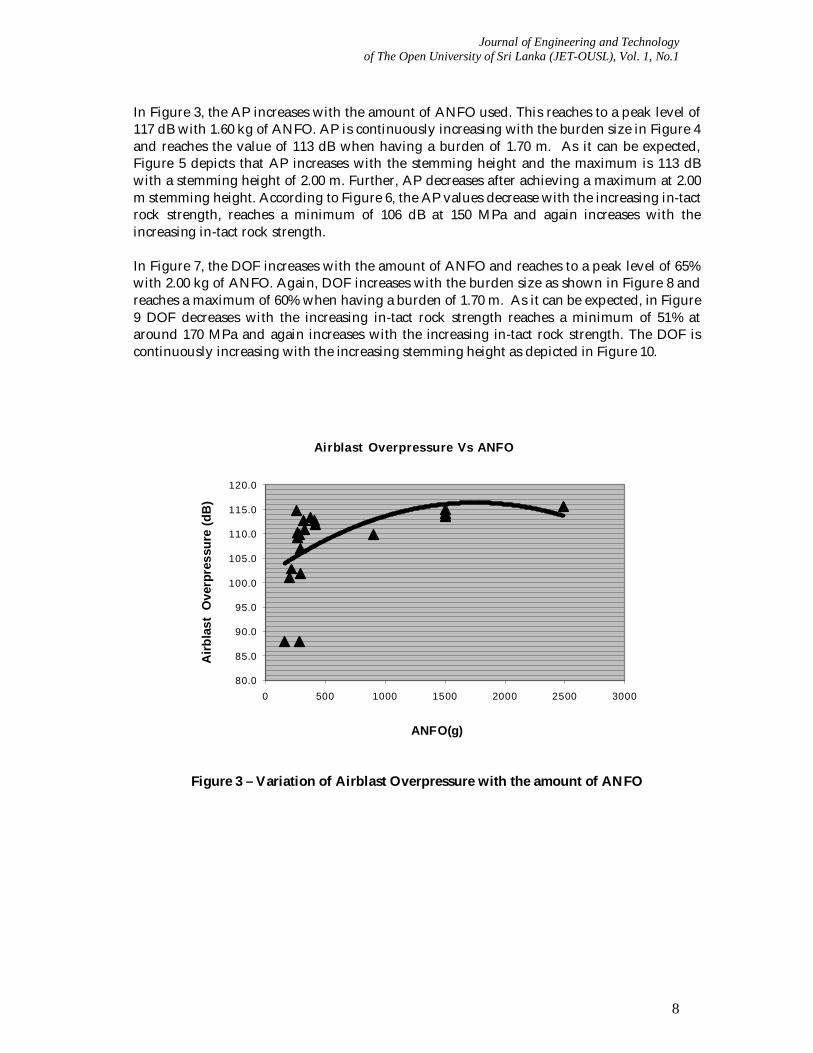
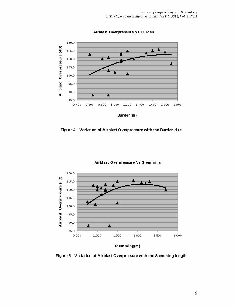
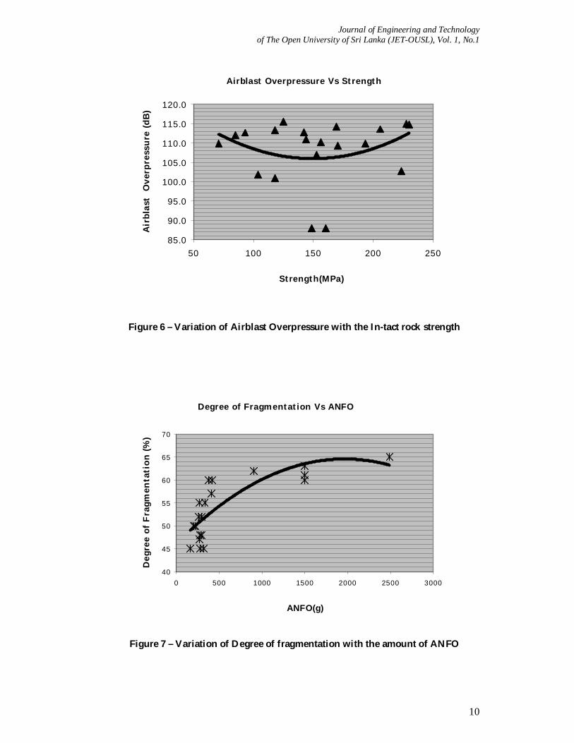
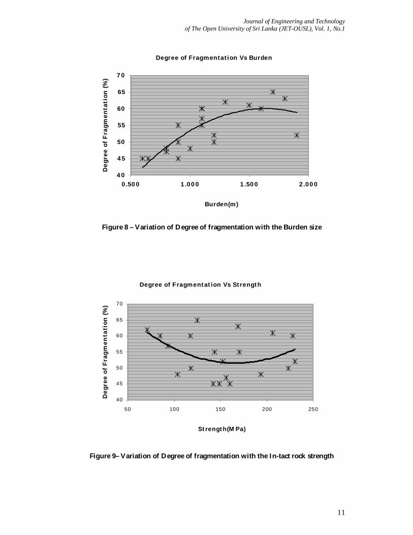
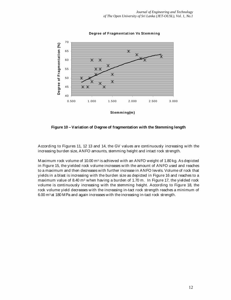
In Figure 3, the AP increases with the amount of ANFO used. This reaches to a peak level of 117 dB with 1.60 kg of ANFO. AP is continuously increasing with the burden size in Figure 4 and reaches the value of 113 dB when having a burden of 1.70 m. As it can be expected, Figure 5 depicts that AP increases with the stemming height and the maximum is 113 dB with a stemming height of 2.00 m. Further, AP decreases after achieving a maximum at 2.00 m stemming height. According to Figure 6, the AP values decrease with the increasing in-tact rock strength, reaches a minimum of 106 dB at 150 MPa and again increases with the increasing in-tact rock strength. In Figure 7, the DOF increases with the amount of ANFO and reaches to a peak level of 65% with 2.00 kg of ANFO. Again, DOF increases with the burden size as shown in Figure 8 and reaches a maximum of 60% when having a burden of 1.70 m. As it can be expected, in Figure 9 DOF decreases with the increasing in-tact rock strength reaches a minimum of 51% at around 170 MPa and again increases with the increasing in-tact rock strength. The DOF is continuously increasing with the increasing stemming height as depicted in Figure 10.
Airblast Overpressure Vs ANFO
80.0
85.0
90.0
95.0
100.0
105.0
110.0
115.0
120.0
0 500 1000 1500 2000 2500 3000
ANFO(g)
Airb
last
Ove
rpre
ssur
e (d
B)
Figure 3 – Variation of Airblast Overpressure with the amount of ANFO
Journal of Engineering and Technology of The Open University of Sri Lanka (JET-OUSL), Vol. 1, No.1
9
Airblast Overpressure Vs Burden
85.0
90.0
95.0
100.0
105.0
110.0
115.0
120.0
0.400 0.600 0.800 1.000 1.200 1.400 1.600 1.800 2.000
Burden(m)
Air
blas
t O
verp
ress
ure
(dB
)
Figure 4 – Variation of Airblast Overpressure with the Burden size
Airblast Overpressure Vs Stemming
85.0
90.0
95.0
100.0
105.0
110.0
115.0
120.0
0.500 1.000 1.500 2.000 2.500 3.000
Stemming(m)
Air
blas
t O
verp
ress
ure
(dB
)
Figure 5 – Variation of Airblast Overpressure with the Stemming length
Journal of Engineering and Technology of The Open University of Sri Lanka (JET-OUSL), Vol. 1, No.1
10
Airblast Overpressure Vs Strength
85.0
90.0
95.0
100.0
105.0
110.0
115.0
120.0
50 100 150 200 250
Strength(MPa)
Air
blas
t O
verp
ress
ure
(dB
)
Figure 6 – Variation of Airblast Overpressure with the In-tact rock strength
Degree of Fragmentation Vs ANFO
40
45
50
55
60
65
70
0 500 1000 1500 2000 2500 3000
ANFO(g)
Deg
ree
of F
ragm
enta
tion
(%)
Figure 7 – Variation of Degree of fragmentation with the amount of ANFO
Journal of Engineering and Technology of The Open University of Sri Lanka (JET-OUSL), Vol. 1, No.1
11
Degree of Fragmentation Vs Burden
40
45
50
55
60
65
70
0.500 1.000 1.500 2.000
Burden(m)
Deg
ree
of F
ragm
enta
tion
(%)
Figure 8 – Variation of Degree of fragmentation with the Burden size
Degree of Fragmentation Vs Strength
40
45
50
55
60
65
70
50 100 150 200 250
Strength(MPa)
Deg
ree
of F
ragm
enta
tion
(%)
Figure 9– Variation of Degree of fragmentation with the In-tact rock strength
Journal of Engineering and Technology of The Open University of Sri Lanka (JET-OUSL), Vol. 1, No.1
12
Degree of Fragmentation Vs Stemming
40
45
50
55
60
65
70
0.500 1.000 1.500 2.000 2.500 3.000
Stemming(m)
Deg
ree
of F
ragm
enta
tion
(%)
Figure 10 – Variation of Degree of fragmentation with the Stemming length
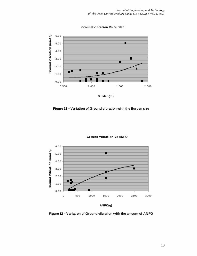
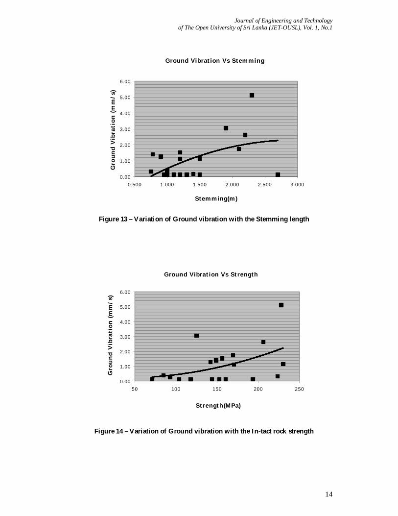
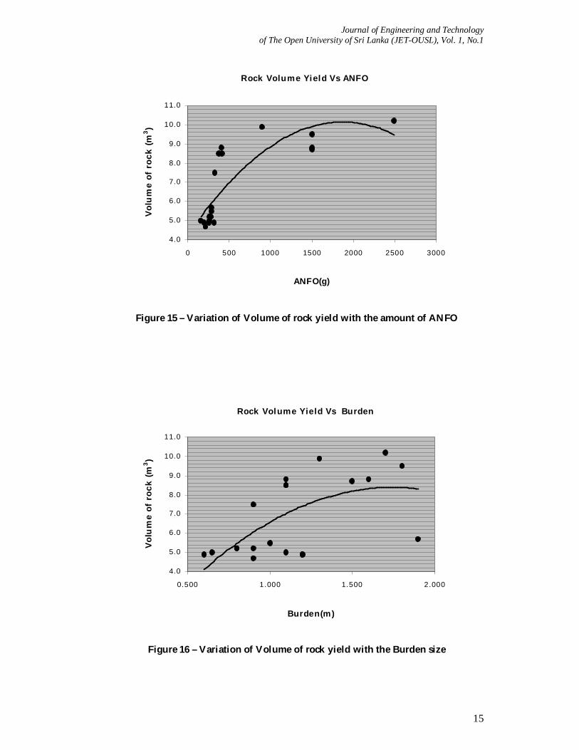
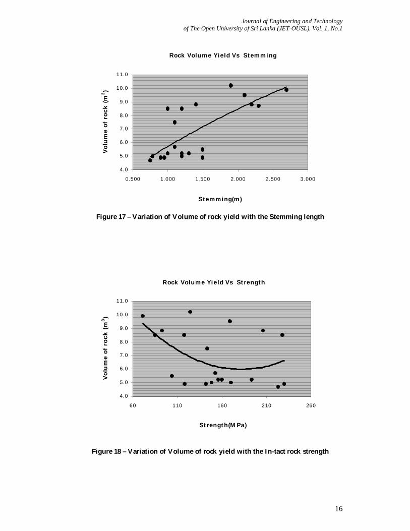
According to Figures 11, 12 13 and 14, the GV values are continuously increasing with the increasing burden size, ANFO amounts, stemming height and intact rock strength. Maximum rock volume of 10.00 m3 is achieved with an ANFO weight of 1.80 kg. As depicted in Figure 15, the yielded rock volume increases with the amount of ANFO used and reaches to a maximum and then decreases with further increase in ANFO levels. Volume of rock that yields in a blast is increasing with the burden size as depicted in Figure 16 and reaches to a maximum value of 8.40 m3 when having a burden of 1.70 m. In Figure 17, the yielded rock volume is continuously increasing with the stemming height. According to Figure 18, the rock volume yield decreases with the increasing in-tact rock strength reaches a minimum of 6.00 m3 at 180 MPa and again increases with the increasing in-tact rock strength.
Journal of Engineering and Technology of The Open University of Sri Lanka (JET-OUSL), Vol. 1, No.1
13
Ground Vibration Vs Burden
0.00
1.00
2.00
3.00
4.00
5.00
6.00
0.500 1.000 1.500 2.000
Burden(m)
Gro
und
Vibr
atio
n (m
m/s
)
Figure 11 – Variation of Ground vibration with the Burden size
Ground Vibration Vs ANFO
0.00
1.00
2.00
3.00
4.00
5.00
6.00
0 500 1000 1500 2000 2500 3000
ANFO(g)
Gro
und
Vibr
atio
n (m
m/s
)
Figure 12 – Variation of Ground vibration with the amount of ANFO
Journal of Engineering and Technology of The Open University of Sri Lanka (JET-OUSL), Vol. 1, No.1
14
Ground Vibration Vs Stemming
0.00
1.00
2.00
3.00
4.00
5.00
6.00
0.500 1.000 1.500 2.000 2.500 3.000
Stemming(m)
Gro
und
Vib
rati
on (m
m/s
)
Figure 13 – Variation of Ground vibration with the Stemming length
Ground Vibration Vs Strength
0.00
1.00
2.00
3.00
4.00
5.00
6.00
50 100 150 200 250
Strength(MPa)
Gro
und
Vib
rati
on (m
m/s
)
Figure 14 – Variation of Ground vibration with the In-tact rock strength
Journal of Engineering and Technology of The Open University of Sri Lanka (JET-OUSL), Vol. 1, No.1
15
Rock Volume Yield Vs ANFO
4.0
5.0
6.0
7.0
8.0
9.0
10.0
11.0
0 500 1000 1500 2000 2500 3000
ANFO(g)
Volu
me
of r
ock
(m3 )
Figure 15 – Variation of Volume of rock yield with the amount of ANFO
Rock Volume Yield Vs Burden
4.0
5.0
6.0
7.0
8.0
9.0
10.0
11.0
0.500 1.000 1.500 2.000
Burden(m)
Volu
me
of r
ock
(m3 )
Figure 16 – Variation of Volume of rock yield with the Burden size
Journal of Engineering and Technology of The Open University of Sri Lanka (JET-OUSL), Vol. 1, No.1
16
Rock Volume Yield Vs Stemming
4.0
5.0
6.0
7.0
8.0
9.0
10.0
11.0
0.500 1.000 1.500 2.000 2.500 3.000
Stemming(m)
Volu
me
of r
ock
(m3 )
Figure 17 – Variation of Volume of rock yield with the Stemming length
Rock Volume Yield Vs Strength
4.0
5.0
6.0
7.0
8.0
9.0
10.0
11.0
60 110 160 210 260
Strength(MPa)
Volu
me
of r
ock
(m3 )
Figure 18 – Variation of Volume of rock yield with the In-tact rock strength
Journal of Engineering and Technology of The Open University of Sri Lanka (JET-OUSL), Vol. 1, No.1
17
5 DISCUSSION. Theoretically, the above results are in agreement with the classical rock blasting practices. When higher amounts of explosives are used, enormous pressure generates inside the borehole, which creates and ejects excessive air blast overpressure to the air when it is released from the borehole. The AP reaches the vulnerable range of 110 dB to 120 dB when more than 800 g of ANFO is used. A burden size more than 1.40 m will create the AP to move into the vulnerable limits and the same will create when the stemming height is more than 1.50 m. AP exceeds 110 dB when the trough oriented AP – intact rock strength curve is below 70 MPa and above 220 Mpa. However, the data are highly scattered and most probably this is due to other intact rock conditions such as variations in mineralogical compositions and texture. Even though a higher degree of fragmentation can be achieved with 2.00 kg of explosives, it will create AP to push into vulnerable limits and when considering this factor, the DOF that can be achieved will limit to 58% which is corresponding to 800 g of ANFO. The burden size which is restricted from AP limits (which is 1.40m) results in a DOF of 58%. However, when the stemming height is increased excessive AP is generated and the DOF is limited due to this excessive AP and the safe stemming height of 1.50 m results in 55% DOF. When applying the safe limit criteria of the above AP to intact rock strength (i.e in between 70 MPa – 220 MPa), a DOF of 61% and 53% can be achieved at its lower and upper bounded values respectively. Again in this case also the data in the intact rock strength plot are highly scattered and the reasons are same as in the AP variation. When applying a blasting parameter set of 800 g of ANFO, 1.40 m of burden size and a stemming height of 1.50m to ground vibration plots, GV values always exit below 2 mm/s, which is quite safe when considering its threshold limit of 5 mm/s. With the application of 800 g ANFO limit, a maximum rock volume of 8.00 m3 can be achieved, while 1.40 m of burden size will yield 8.00 m3 again. A rock volume of 7.20 m3 will yield with the use of 1.50 m of stemming height. The safe intact rock strength region will produce a rock volume of 9.40 m3 and its lower limit and 6.40 m3 at the upper limit. 6 CONCLUSIONS In addressing the main objectives of this study, following conclusions can be made. 6.1 Impact of Blasting Parameters on Production output and Environmental effects
1. A maximum rock volume of 10.00 m3 can be achieved with 2.00 kg of ANFO. Further increase of ANFO will result in the decrease of yielded rock volume. However, this value is limited to 8.40 m3 with a maximum burden size of 1.70 m. The increasing stemming height continuously increases the yield and the corresponding height at the maximum yield is 2.70 m.
2. The degree of fragmentation increases with ANFO levels and reaches the maximum of
65% with 2.00 kg of ANFO and further addition of ANFO will result in the
3. This maximum value of DOF is limited by the effects of burden size and reduces its value to 51% with a burden size of 1.70 m. The same maximum degree of fragmentation of 51%
Journal of Engineering and Technology of The Open University of Sri Lanka (JET-OUSL), Vol. 1, No.1
18
can be achieved with intact rock strength of 170 MPa. The rising stemming height continuously increases the yield and the corresponding stemming height at the maximum DOF, is 2.70 m.
4. The air blast overpressure values increase with the increasing ANFO levels and this trend
is the same for burden size. With the increasing stemming height, the AP increases and it reaches to a maximum of 113 dB with a stemming height of 2.00 m and further addition of ANFO will reduce the airblast overpressure. The airblast overpressure decreases with the increasing intact rock strength, reaches to a minimum of 106 dB at 150 MPa and increases thereafter.
5. The ground vibration levels increase with the rising values of all blasting parameters and
also with the intact rock strength. 6. When considering the maximum production output view, from the above conclusions, it
can be proposed to use 2.00 kg of ANFO with a burden size of 1.70 m. A stemming height of 2.70 m will produce a rock yield volume of 8.40 m3 with a degree of fragmentation of at least 51% from a rock mass with intact rock strength of 170 MPa. These parametric conditions will cause environmental hazards. Therefore, these blasting parameters can be effectively utilized in isolated quarry areas.
6.2 Optimum Set of Blasting Parameters for Minimum Environmental Impacts that
Produces Maximum Production Output 1. The safe allowable airblast overpressure imposed by GSMB is 110 dB. To meet this
requirement, a weight less than 800 g of ANFO should be used. Also, a burden size less than 1.40 m should be adopted to mitigate AP problems. The stemming height should be maintained less than 1.50 m (not too small, which again cause to AP problems). AP exceeds safety limits when the intact rock strength is below 70 MPa and above 220 Mpa.
2. When considering the above mentioned parameters in (1), the maximum degree of
fragmentation that can be achieved under safe AP conditions is 55% and the maximum rock volume that can be obtained is limited to 7.20 m3.
3. The above set of blasting parameters firmly fits to the safe ground vibration levels which
always exits below 2 mm/s and is quite safe when considering its threshold limit of 5 mm/s.
7 FURTHER RECOMMENDATIONS This study was focused to make a base to develop a set of blasting parameters that will suit best for a given rock type. However, due to various constraints, impact of other blasting parameters and intact rock conditions on blasting performance was unable to investigate. Further, in this study the impact on Fly rocks was also not performed as blasting operations were carried out under restricted conditions. Hence it is highly recommended to use these parameters in the industry with a sense in the impact from other non investigated parameters also.
Journal of Engineering and Technology of The Open University of Sri Lanka (JET-OUSL), Vol. 1, No.1
19
REFERENCES 1. Cooray, P.G. (1984), Introduction to Geology of Sri Lanka, National museum of Sri Lanka,
Sri Lanka, Second edition, 49-114 pp. 2. Cooray, P.G. (1994), The Precambrian of Sri Lanka: a historical review, Precambrian
Research, 66(1994) 3 – 18. Elsevier Science B.V, Amsterdam. 3. Carcedo, F.J, Jimeno, C.L and Jimeno, E.L and (1995), Drilling and Blasting of Rocks, A.A.
Balkema/Rotterdam/Brookfield, Netherland, Revised edition, 93 -203 pp.
4. Hoek, E. & Bray J.W. (1981), Rock Slope Engineering, Institution of Mining & Metallurgy, New York, Revised third edition, 142-168 pp.
5. Sweet, K. (1988), Open Cast Mining, Institution of Mining & Metallurgy, New York, First
edition, 34-47 pp.
6. Waltham, T. (2002), Foundation of Engineering Geology, Spon Press, London, Second edition, 17-68 pp.
7. www.uet.edu.pk, visited 10.09.2009 8. www.arpnjournals.com, visited 10.09.2009