Embed Size (px)
Citation preview
OPTIMUM PERFORMANCE
RELAYS & FLASHER UNITS
Product / Technical Information
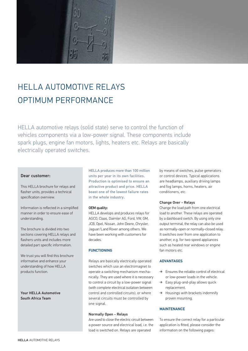
HELLA AUTOMOTIVE RELAYS
HELLA automotive relays (solid state) serve to control the function of vehicles components via a low-power signal. These components include spark plugs, engine fan motors, lights, heaters etc. Relays are basically electrically operated switches.
HELLA AUTOMOTIVE RELAYSOPTIMUM PERFORMANCE
HELLA produces more than 100 million
units per year in its own facilities.
Production is optimised to ensure an
attractive product and price. HELLA
boast one of the lowest failure rates
in the whole industry.
OEM quality:
HELLA develops and produces relays for AGCO, Claas, Daimler AG, Ford, VW, GM, JCB, Opel, Nissan, John Deere, Chrysler, Jaguar/Land Rover among others. We have been working with customers for decades.
FUNCTIONING
Relays are basically electrically operated switches which use an electromagnet to operate a switching mechanism mecha-nically. They are used where it is necessary to control a circuit by a low-power signal (with complete electrical isolation between control and controlled circuits), or where several circuits must be controlled by one signal.
Normally Open - Relays Are used to close the electric circuit between a power source and electrical load, i.e. the load is switched on. Relays are operated
by means of switches, pulse generators or control devices. Typical applications are headlamps, auxiliary driving lamps and fog lamps, horns, heaters, air conditioners, etc.
Change Over - Relays
Change the load path from one electrical load to another. These relays are operated by a dashboard switch. By using only one output terminal, the relay can also be used as normally-open or normally-closed relay. It switches over from one application to another, e.g. for two speed appliances such as heated rear windows or engine fan motors etc. ADVANTAGES
Ensures the reliable control of electrical or low-power loads in the vehicle.
Easy plug-and-play allows quick replacement.
Housings with brackets indemnify proven mounting.
MAINTENANCE
To ensure the correct relay for a particular application is fitted, please consider the information on the following pages:
Dear customer:
This HELLA brochure for relays and flasher units, provides a technical specification overview.
Information is reflected in a simplified manner in order to ensure ease of understanding.
The brochure is divided into two sections covering HELLA relays and flashers units and includes more detailed part specific information.
We trust you will find this brochure informative and enhance your understanding of how HELLA products function.
Your HELLA Automotive
South Africa Team
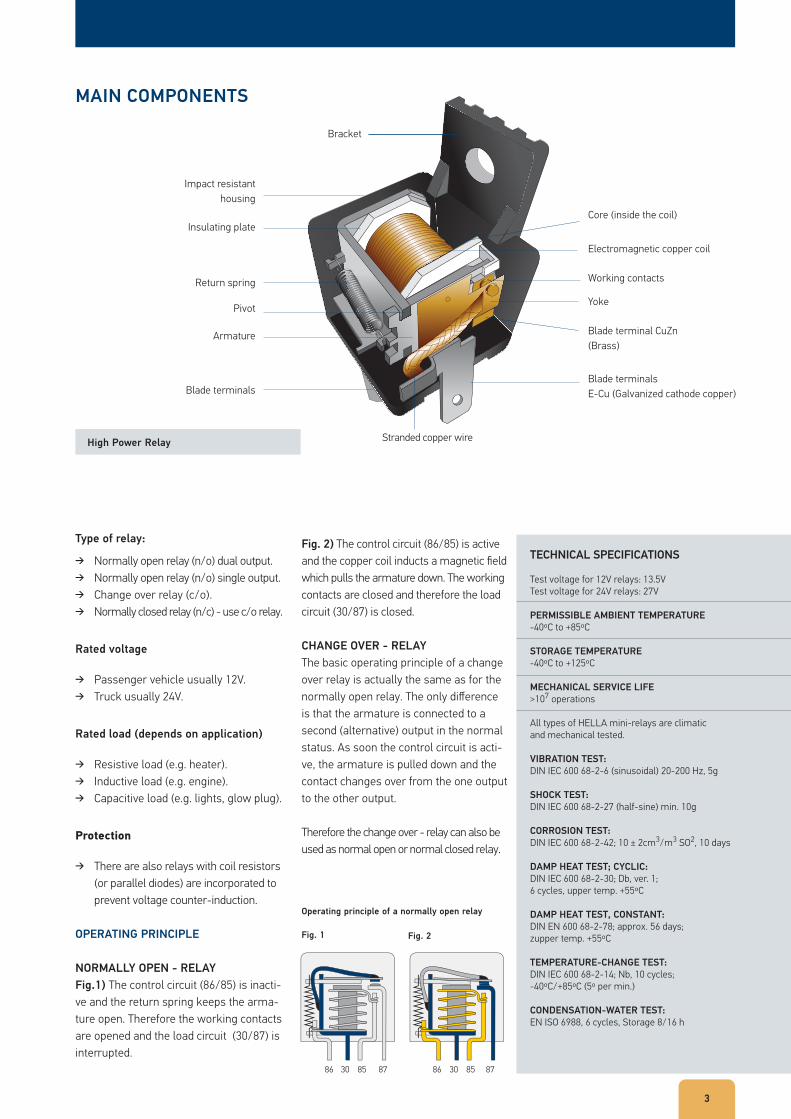
MAIN COMPONENTS
TECHNICAL SPECIFICATIONS
Test voltage for 12V relays: 13.5VTest voltage for 24V relays: 27V
PERMISSIBLE AMBIENT TEMPERATURE
-40ºC to +85ºC
STORAGE TEMPERATURE
-40ºC to +125ºC
MECHANICAL SERVICE LIFE
>107 operations
All types of HELLA mini-relays are climatic and mechanical tested.
VIBRATION TEST:
DIN IEC 600 68-2-6 (sinusoidal) 20-200 Hz, 5g
SHOCK TEST:
DIN IEC 600 68-2-27 (half-sine) min. 10g
CORROSION TEST:
DIN IEC 600 68-2-42; 10 ± 2cm3/m3 SO2, 10 days
DAMP HEAT TEST; CYCLIC:
DIN IEC 600 68-2-30; Db, ver. 1; 6 cycles, upper temp. +55ºC
DAMP HEAT TEST, CONSTANT:
DIN EN 600 68-2-78; approx. 56 days; zupper temp. +55ºC
TEMPERATURE-CHANGE TEST:
DIN IEC 600 68-2-14; Nb, 10 cycles; -40ºC/+85ºC (5º per min.)
CONDENSATION-WATER TEST:
EN ISO 6988, 6 cycles, Storage 8/16 h
Type of relay:
Normally open relay (n/o) dual output. Normally open relay (n/o) single output. Change over relay (c/o). Normally closed relay (n/c) - use c/o relay.
Rated voltage
Passenger vehicle usually 12V. Truck usually 24V.
Rated load (depends on application)
Resistive load (e.g. heater). Inductive load (e.g. engine). Capacitive load (e.g. lights, glow plug).
Protection
There are also relays with coil resistors (or parallel diodes) are incorporated to prevent voltage counter-induction.
OPERATING PRINCIPLE
NORMALLY OPEN - RELAY
Fig.1) The control circuit (86/85) is inacti-ve and the return spring keeps the arma-ture open. Therefore the working contacts are opened and the load circuit (30/87) is interrupted.
3
Armature
Return spring
Pivot Yoke
Blade terminal CuZn (Brass)
Working contacts
Electromagnetic copper coil
Core (inside the coil)
Blade terminals E-Cu (Galvanized cathode copper)Blade terminals
Impact resistanthousing
Insulating plate
Bracket
Stranded copper wireHigh Power Relay
Operating principle of a normally open relay
Fig. 1 Fig. 2
Fig. 2) The control circuit (86/85) is active and the copper coil inducts a magnetic field which pulls the armature down. The working contacts are closed and therefore the load circuit (30/87) is closed.
CHANGE OVER - RELAY
The basic operating principle of a change over relay is actually the same as for the normally open relay. The only difference is that the armature is connected to a second (alternative) output in the normal status. As soon the control circuit is acti-ve, the armature is pulled down and the contact changes over from the one output to the other output.
Therefore the change over - relay can also be used as normal open or normal closed relay.
86 30 85 8786 30 85 87
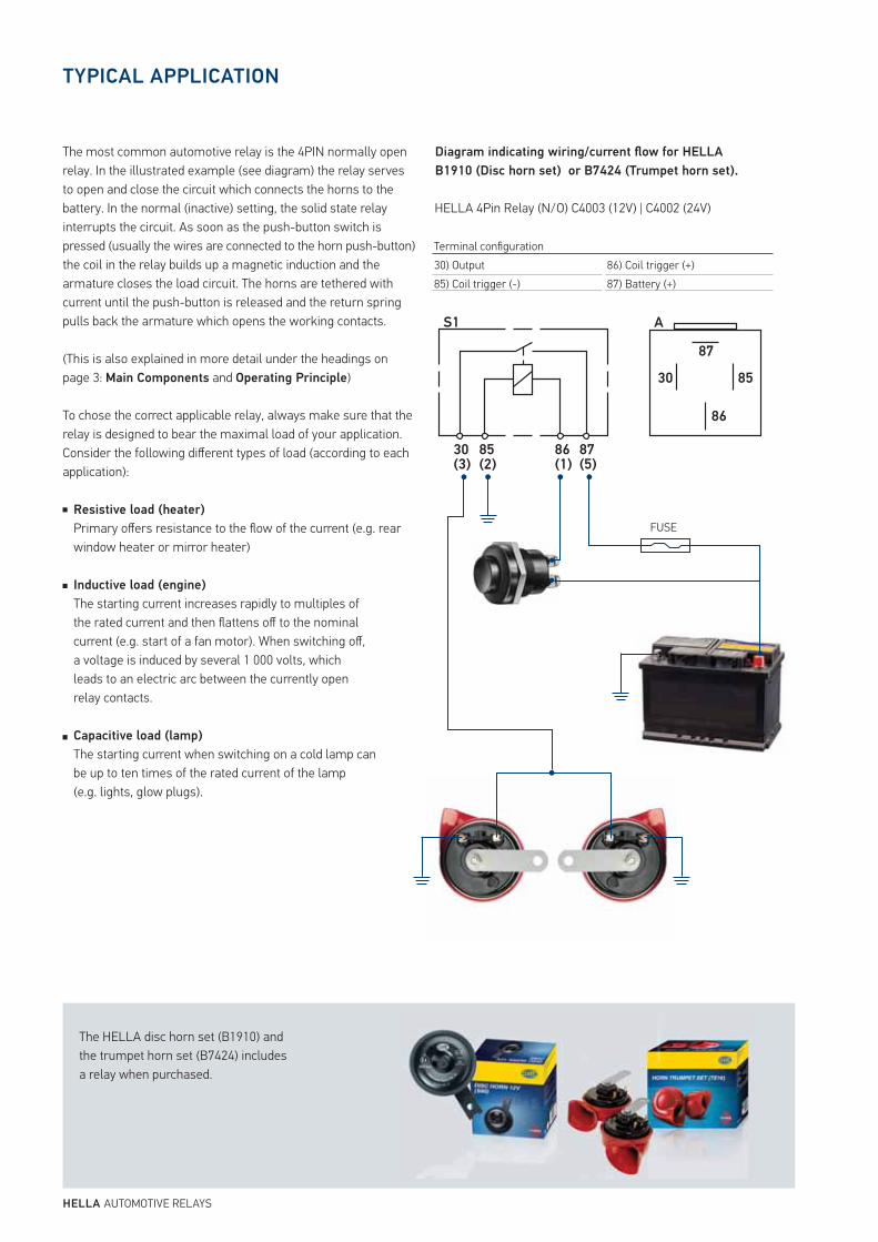
TYPICAL APPLICATION
The most common automotive relay is the 4PIN normally open relay. In the illustrated example (see diagram) the relay serves to open and close the circuit which connects the horns to the battery. In the normal (inactive) setting, the solid state relay interrupts the circuit. As soon as the push-button switch is pressed (usually the wires are connected to the horn push-button) the coil in the relay builds up a magnetic induction and the armature closes the load circuit. The horns are tethered with current until the push-button is released and the return spring pulls back the armature which opens the working contacts.
(This is also explained in more detail under the headings on page 3: Main Components and Operating Principle)
To chose the correct applicable relay, always make sure that the relay is designed to bear the maximal load of your application. Consider the following different types of load (according to each application):
Resistive load (heater)
Primary offers resistance to the flow of the current (e.g. rear window heater or mirror heater)
Inductive load (engine)
The starting current increases rapidly to multiples ofthe rated current and then flattens off to the nominalcurrent (e.g. start of a fan motor). When switching off,a voltage is induced by several 1 000 volts, which leads to an electric arc between the currently open relay contacts.
Capacitive load (lamp)
The starting current when switching on a cold lamp canbe up to ten times of the rated current of the lamp(e.g. lights, glow plugs).
Diagram indicating wiring/current flow for HELLA
B1910 (Disc horn set) or B7424 (Trumpet horn set).
HELLA 4Pin Relay (N/O) C4003 (12V) | C4002 (24V)
Terminal configuration30) Output85) Coil trigger (-)
86) Coil trigger (+)87) Battery (+)
HELLA AUTOMOTIVE RELAYS
S1
30(3)
85(2)
86(1)
87
30 85
86
87(5)
A
FUSE
The HELLA disc horn set (B1910) and the trumpet horn set (B7424) includes a relay when purchased.
55
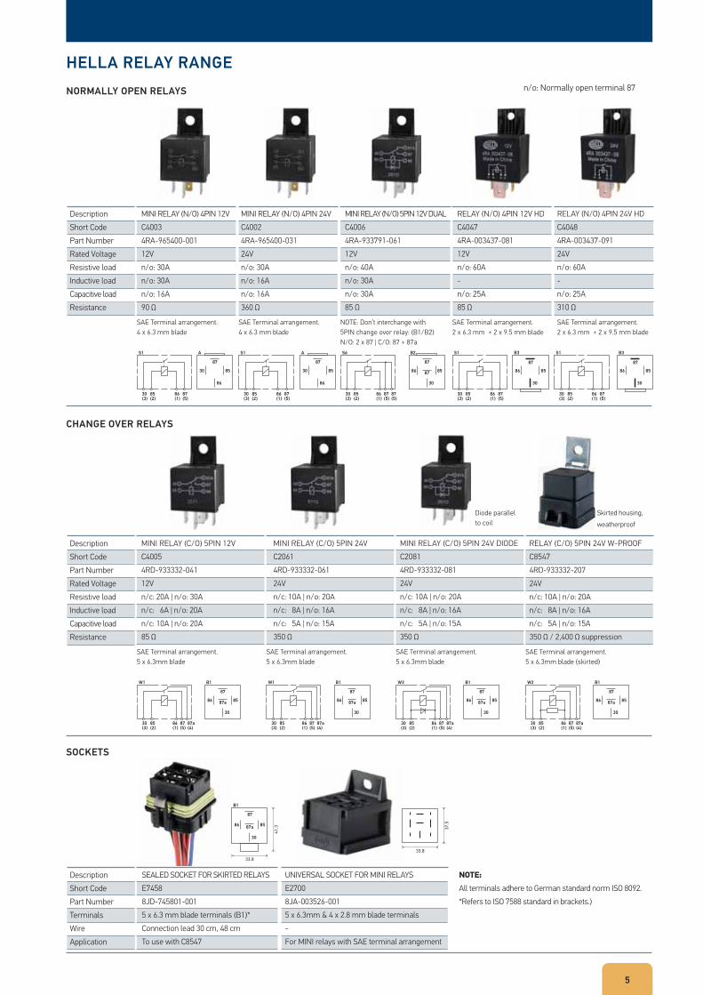
HELLA RELAY RANGE
NORMALLY OPEN RELAYS
CHANGE OVER RELAYS
SOCKETS
DescriptionShort CodePart NumberRated VoltageResistive loadInductive loadCapacitive loadResistance
DescriptionShort CodePart NumberRated VoltageResistive loadInductive loadCapacitive loadResistance
DescriptionShort CodePart NumberTerminalsWireApplication
n/o: Normally open terminal 87
SAE Terminal arrangement.4 x 6.3 mm blade
SAE Terminal arrangement.5 x 6.3mm blade
SAE Terminal arrangement.5 x 6.3mm blade
SAE Terminal arrangement.5 x 6.3mm blade
SAE Terminal arrangement.5 x 6.3mm blade (skirted)
SAE Terminal arrangement.4 x 6.3 mm blade
SAE Terminal arrangement.2 x 6.3 mm + 2 x 9.5 mm blade
SAE Terminal arrangement.2 x 6.3 mm + 2 x 9.5 mm blade
NOTE: Don’t interchange with 5PIN change over relay: (B1/B2) N/O: 2 x 87 | C/O: 87 + 87a
MINI RELAY (N/O) 4PIN 12VC40034RA-965400-00112Vn/o: 30An/o: 30An/o: 16A90 Ω
MINI RELAY (C/O) 5PIN 12VC40054RD-933332-04112V n/c: 20A | n/o: 30An/c: 6A | n/o: 20An/c: 10A | n/o: 20A85 Ω
MINI RELAY (C/O) 5PIN 24VC20614RD-933332-06124V n/c: 10A | n/o: 20An/c: 8A | n/o: 16An/c: 5A | n/o: 15A350 Ω
MINI RELAY (C/O) 5PIN 24V DIODEC20814RD-933332-08124Vn/c: 10A | n/o: 20An/c: 8A | n/o: 16An/c: 5A | n/o: 15A350 Ω
Diode parallel to coil
Skirted housing, weatherproof
RELAY (C/O) 5PIN 24V W-PROOFC85474RD-933332-20724Vn/c: 10A | n/o: 20An/c: 8A | n/o: 16An/c: 5A | n/o: 15A350 Ω / 2,400 Ω suppression
SEALED SOCKET FOR SKIRTED RELAYSE74588JD-745801-0015 x 6.3 mm blade terminals (B1)*Connection lead 30 cm, 48 cmTo use with C8547
MINI RELAY (N/O) 4PIN 24VC40024RA-965400-03124Vn/o: 30An/o: 16An/o: 16A360 Ω
UNIVERSAL SOCKET FOR MINI RELAYSE27008JA-003526-0015 x 6.3mm & 4 x 2.8 mm blade terminals-For MINI relays with SAE terminal arrangement
NOTE:All terminals adhere to German standard norm ISO 8092.*Refers to ISO 7588 standard in brackets.)
MINI RELAY (N/O) 5PIN 12V DUALC40064RA-933791-06112Vn/o: 40An/o: 30An/o: 30A85 Ω
RELAY (N/O) 4PIN 12V HDC40474RA-003437-08112Vn/o: 60A-n/o: 25A85 Ω
RELAY (N/O) 4PIN 24V HDC40484RA-003437-09124Vn/o: 60A-n/o: 25A310 Ω
S1
30(3)
85(2)
86(1)
87(5)
S1
30(3)
85(2)
86(1)
87(5)
S1
30(3)
85(2)
86(1)
87(5)
87
30 85
86
A S1
30(3)
85(2)
86(1)
87(5)
87
30 85
86
A S6
30(3)
85(2)
86(1)
87(5)
87(5)
87
86 85
30
87
B2
87
86 85
30
B3
87
86 85
30
B3
W1
30(3)
85(2)
86(1)
87
86 85
30
87a(4)
87(5)
87a
B1 W1
30(3)
85(2)
86(1)
87
86 85
30
87a(4)
87(5)
87a
B1 W3
30(3)
85(2)
86(1)
87
86 85
30
87a(4)
87(5)
87a
B1 W2
30(3)
85(2)
86(1)
87
86 85
30
87a(4)
87(5)
87a
B1
87
86 85
30
87a
33.8
41.3
B1
33.8
37.5
HELLA AUTOMOTIVE FLASHER UNITS
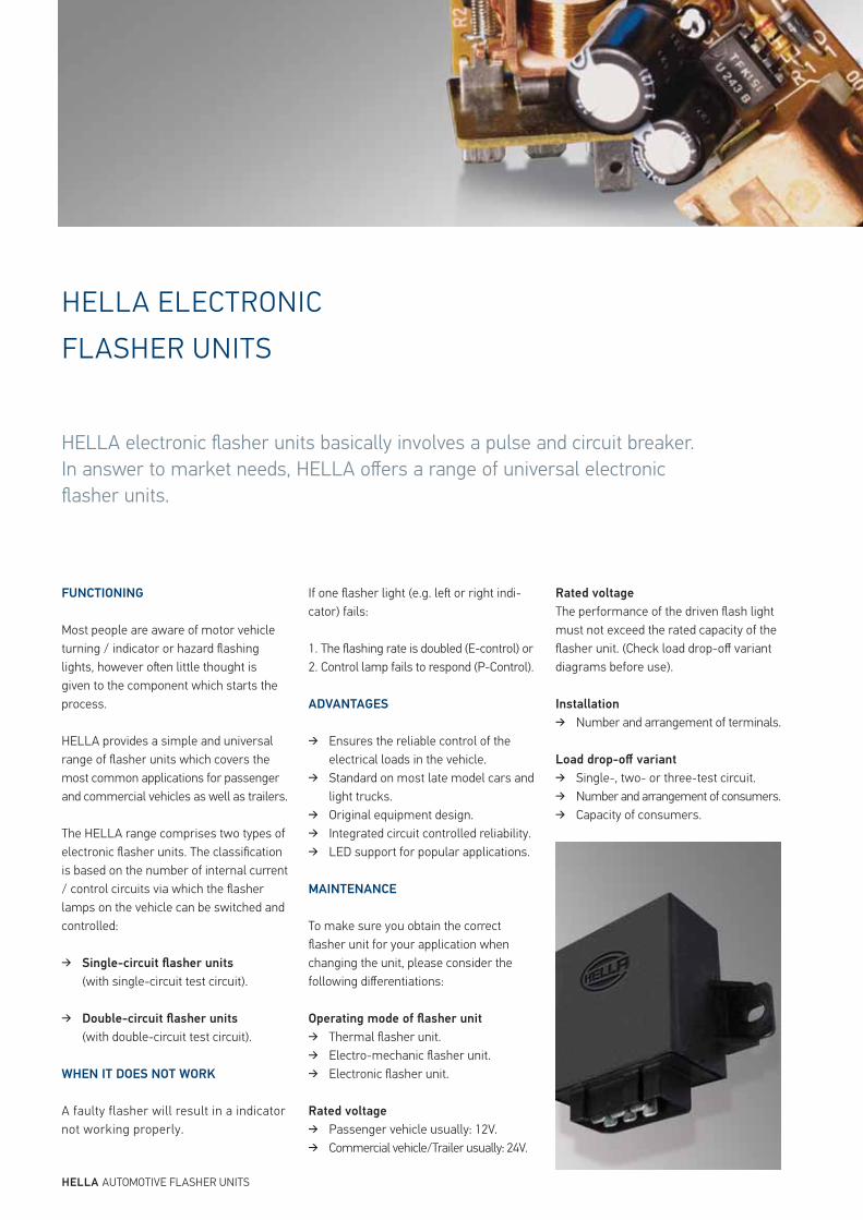
HELLA ELECTRONIC FLASHER UNITS
FUNCTIONING
Most people are aware of motor vehicle turning / indicator or hazard flashing lights, however oen little thought is given to the component which starts the process.
HELLA provides a simple and universal range of flasher units which covers the most common applications for passenger and commercial vehicles as well as trailers.
The HELLA range comprises two types of electronic flasher units. The classification is based on the number of internal current / control circuits via which the flasher lamps on the vehicle can be switched and controlled:
Single-circuit flasher units (with single-circuit test circuit).
Double-circuit flasher units (with double-circuit test circuit).
WHEN IT DOES NOT WORK
A faulty flasher will result in a indicator not working properly.
If one flasher light (e.g. le or right indi-cator) fails:
1. The flashing rate is doubled (E-control) or2. Control lamp fails to respond (P-Control).
ADVANTAGES
Ensures the reliable control of the electrical loads in the vehicle.
Standard on most late model cars and light trucks.
Original equipment design. Integrated circuit controlled reliability. LED support for popular applications.
MAINTENANCE
To make sure you obtain the correct flasher unit for your application when changing the unit, please consider the following differentiations: Operating mode of flasher unit
Thermal flasher unit. Electro-mechanic flasher unit. Electronic flasher unit.
Rated voltage
Passenger vehicle usually: 12V. Commercial vehicle/Trailer usually: 24V.
Rated voltage
The performance of the driven flash light must not exceed the rated capacity of the flasher unit. (Check load drop-off variant diagrams before use).
Installation
Number and arrangement of terminals. Load drop-off variant
Single-, two- or three-test circuit. Number and arrangement of consumers. Capacity of consumers.
HELLA electronic flasher units basically involves a pulse and circuit breaker. In answer to market needs, HELLA offers a range of universal electronic flasher units.
TECHNICAL SPECIFICATIONS
Test voltage for 12V relays: 13VTest voltage for 24V relays: 28V
OPERATING TEMPERATURE
-30ºC to +80º C
STORAGE TEMPERATURE
-40ºC to +90º C
FLASHING RATES
90 ± flashes/min.
DEVICE PROTECTION SYSTEM
IP 53 DIN 40050
CONTROL TYPE**12V: E/P, EP, PP, PPP | 24V: EP, PP
VOLTAGE DROP
49 → 49a< 450 mV
All types of HELLA flasher units comply with national and international regulations.
StVZO § 54 turn indicator.
ECE Directive 48 lighting equipment.
EEC Directive 76/756 lighting equipment.
US Federal Standard FMVSS 108 lighting
equipment.
SAE J 590 Turn signal flasher unit.
SAE J 945 Hazard warning flasher unit.
EEC Directive 72/245 radio interference
suppression.
HISTORIC FLASHER DEVELOPMENT
Basically each flasher unit consists of a pulse and a circuit breaker. There are three different main operating principles.
The first mechanical flasher used a bimetallic strip to generate a delayed output, which was heated by a heating coil. The bimetallic strip was designed as a break contact with a heating coil connected in series.
Following developments a hot wire and a solenoid to generate the repetitive signal delayed output was used. However, as the working principle was based on mechanical characteristics such as tension of the wire and electrical resistance, these units were very sensitive to low voltage and humidity.
This was followed by the development of electro-mechanic flasher units. Those used a single capacitor and were dependant on mechanical characteristics susceptible to environmental influences.
Towards the end of the 1960‘s, the first solely electronic flasher unit with dual capacitor was developed. These were much more accurate and lasted longer than all former flasher units.
7
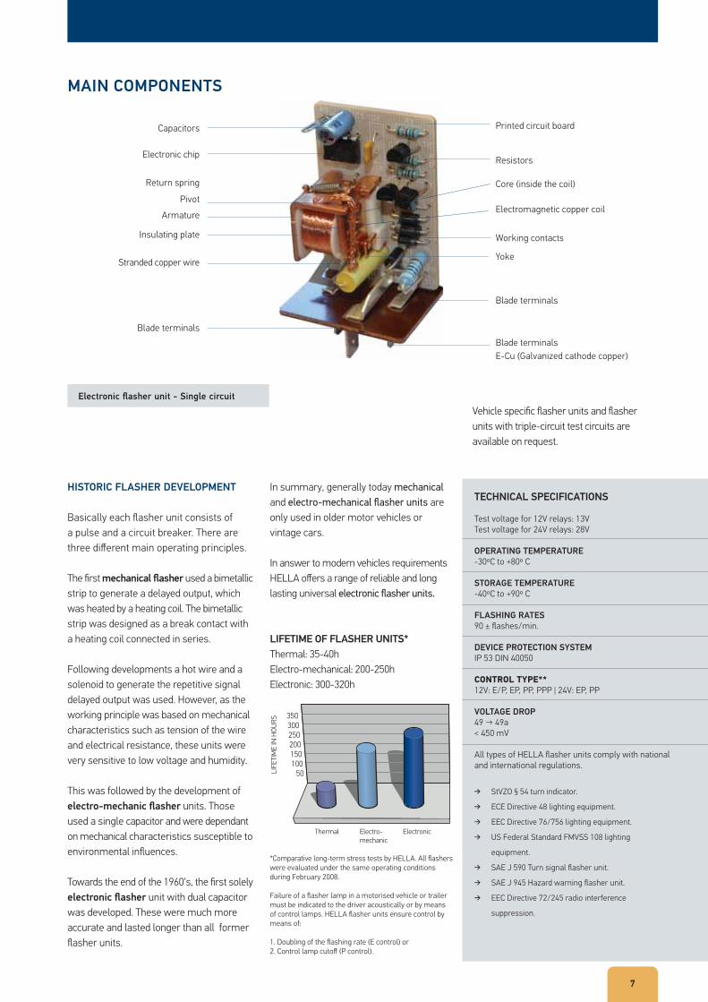
Electronic flasher unit - Single circuit
In summary, generally today mechanical and electro-mechanical flasher units are only used in older motor vehicles or vintage cars.
In answer to modern vehicles requirements HELLA offers a range of reliable and long lasting universal electronic flasher units.
LIFETIME OF FLASHER UNITS*
Thermal: 35-40hElectro-mechanical: 200-250hElectronic: 300-320h
Vehicle specific flasher units and flasher units with triple-circuit test circuits are available on request.
*Comparative long-term stress tests by HELLA. All flashers were evaluated under the same operating conditions during February 2008.
Failure of a flasher lamp in a motorised vehicle or trailer must be indicated to the driver acoustically or by means of control lamps. HELLA flasher units ensure control by means of:
1. Doubling of the flashing rate (E control) or 2. Control lamp cutoff (P control).
50100150200250300350
LIFE
TIM
E IN
HOU
RS
Thermal Electro-mechanic
Electronic
MAIN COMPONENTS
Armature
Return spring
Capacitors
Electronic chip
Pivot
Yoke
Blade terminals
Working contacts
Electromagnetic copper coil
Core (inside the coil)
Printed circuit board
Resistors
Blade terminals E-Cu (Galvanized cathode copper)
Blade terminals
Insulating plate
Stranded copper wire
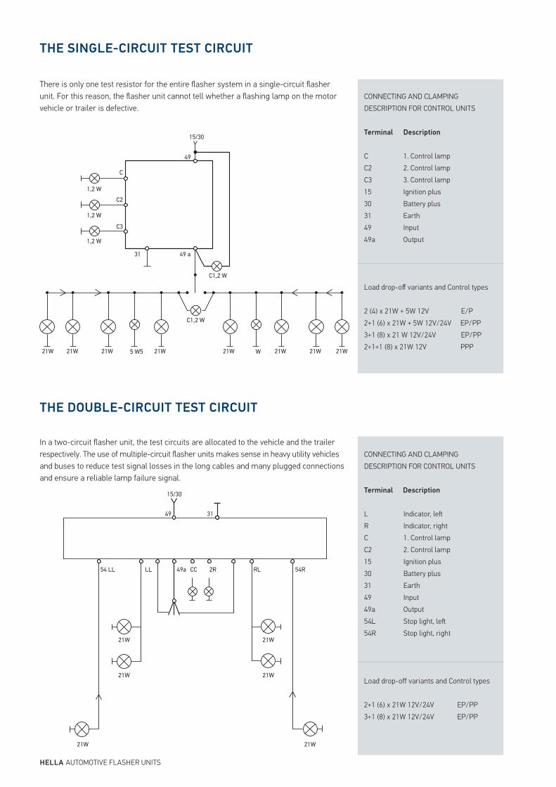
THE SINGLECIRCUIT TEST CIRCUIT
THE DOUBLECIRCUIT TEST CIRCUIT
There is only one test resistor for the entire flasher system in a single-circuit flasher unit. For this reason, the flasher unit cannot tell whether a flashing lamp on the motor vehicle or trailer is defective.
In a two-circuit flasher unit, the test circuits are allocated to the vehicle and the trailer respectively. The use of multiple-circuit flasher units makes sense in heavy utility vehicles and buses to reduce test signal losses in the long cables and many plugged connections and ensure a reliable lamp failure signal.
CONNECTING AND CLAMPINGDESCRIPTION FOR CONTROL UNITS
Terminal
CC2C31530314949a
Description
1. Control lamp2. Control lamp3. Control lampIgnition plusBattery plusEarthInputOutput
CONNECTING AND CLAMPINGDESCRIPTION FOR CONTROL UNITS
Terminal Description
LRCC21530314949a54L54R
Indicator, leIndicator, right1. Control lamp2. Control lampIgnition plusBattery plusEarthInputOutputStop light, leStop light, right
Load drop-off variants and Control types
2 (4) x 21W + 5W 12V E/P2+1 (6) x 21W + 5W 12V/24V EP/PP3+1 (8) x 21 W 12V/24V EP/PP2+1+1 (8) x 21W 12V PPP
Load drop-off variants and Control types
2+1 (6) x 21W 12V/24V EP/PP3+1 (8) x 21W 12V/24V EP/PP
HELLA AUTOMOTIVE FLASHER UNITS
21W 21W 21W 21W
C1,2 W
C1,2 W
49 a31
1,2 W
1,2 W
1,2 W
C
15/30
49
C2
C3
21W 21W 21W 21W5 W5 W
21W 21W
21W
21W
21W
21W
54 LL LL 49a CC 2R RL 54R
15/30
49 31
59
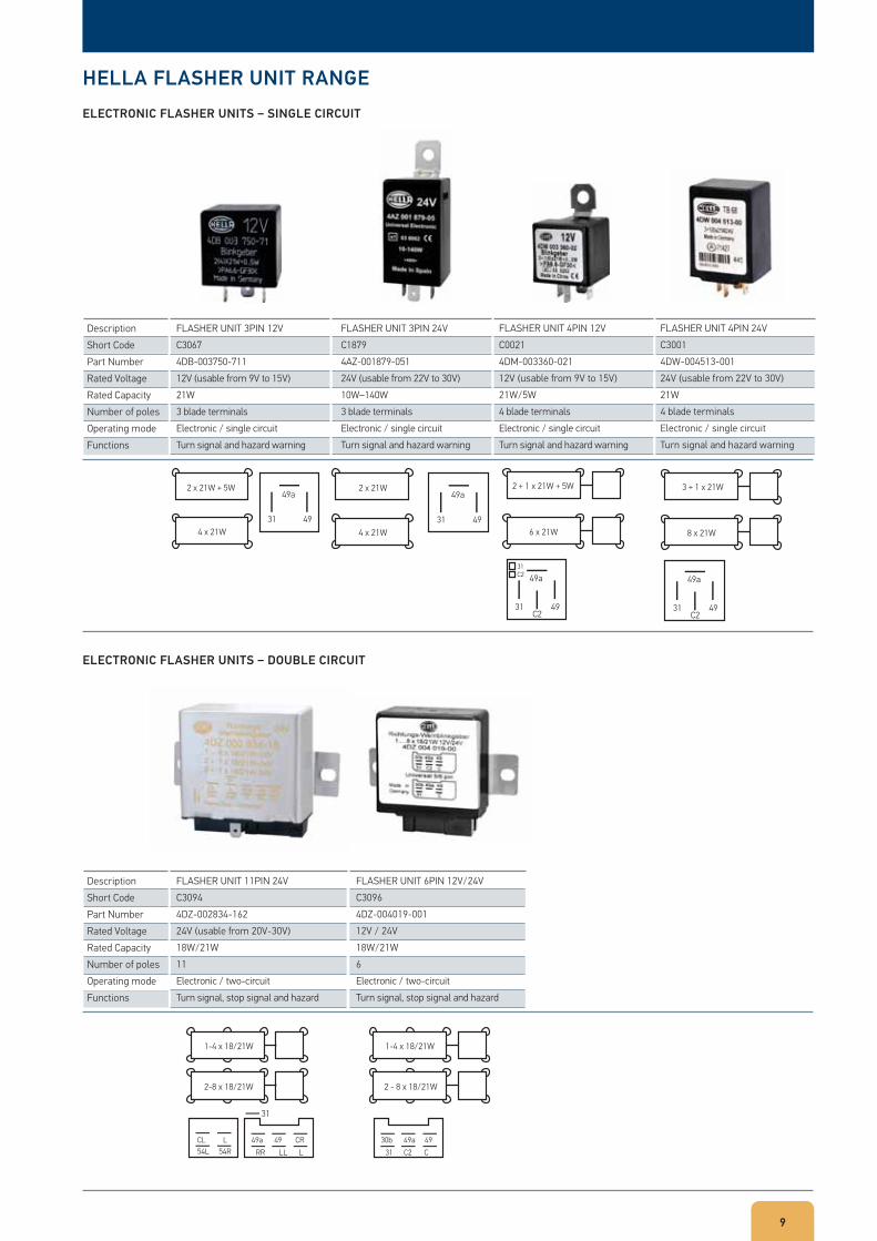
HELLA FLASHER UNIT RANGE
ELECTRONIC FLASHER UNITS SINGLE CIRCUIT
ELECTRONIC FLASHER UNITS DOUBLE CIRCUIT
DescriptionShort CodePart NumberRated VoltageRated CapacityNumber of polesOperating modeFunctions
DescriptionShort CodePart NumberRated VoltageRated CapacityNumber of polesOperating modeFunctions
FLASHER UNIT 3PIN 12VC30674DB-003750-71112V (usable from 9V to 15V)21W3 blade terminalsElectronic / single circuitTurn signal and hazard warning
FLASHER UNIT 11PIN 24VC30944DZ-002834-16224V (usable from 20V-30V)18W/21W11Electronic / two-circuitTurn signal, stop signal and hazard
FLASHER UNIT 3PIN 24VC18794AZ-001879-05124V (usable from 22V to 30V)10W–140W3 blade terminalsElectronic / single circuitTurn signal and hazard warning
FLASHER UNIT 6PIN 12V/24VC30964DZ-004019-00112V / 24V18W/21W6Electronic / two-circuitTurn signal, stop signal and hazard
FLASHER UNIT 4PIN 12VC00214DM-003360-02112V (usable from 9V to 15V)21W/5W4 blade terminalsElectronic / single circuitTurn signal and hazard warning
FLASHER UNIT 4PIN 24VC30014DW-004513-00124V (usable from 22V to 30V)21W4 blade terminalsElectronic / single circuitTurn signal and hazard warning
49a2 x 21W + 5W
4 x 21W31 49
2 x 21W
4 x 21W
49a
31 49
2 + 1 x 21W + 5W
6 x 21W
49a31C2
31 49C2
3 + 1 x 21W
8 x 21W
49a
31 49C2
2-8 x 18/21W
31
1-4 x 18/21W
49aCL L54L 54R
49 CRRR LL L
2 - 8 x 18/21W
1-4 x 18/21W
30b 49a 4931 C2 C
Notes
HELLA AUTOMOTIVE FLASHER UNITS

11
Notes
HELLA Automotive South Africa (Pty) Ltd.
P O Box 6130Moselville, Uitenhage,SOUTH AFRICA6230
Sales Telephone: +27 (0) 41 996-5700Sales Telefax: +27 (0) 41 996-5720www.hella.co.za
© HELLA KGaA Hueck & Co., Lippstadt PN: Z9007 06.2012Printed in South Africa