Embed Size (px)
Citation preview

Design Guide
Oracle Application Server 10g Deployment with Cisco Application Control Engine Deployment Guide, Version 1.1
This design guide describes how to deploy The Cisco® Application Control Engine (Cisco ACE) by Cisco Systems® with Oracle Application Server 10g. This guide was created through the collaborative efforts of Cisco and Oracle as a part of a larger effort to provide Cisco and Oracle solutions to the market. Additional design guides for other product combinations, and other related documents are available from Cisco and Oracle.
Oracle Application Server 10g offers a comprehensive solution for developing, integrating, and deploying enterprise applications, portals, and Web services. Based on a powerful and scalable J2EE server, Oracle Application Server 10g provides complete business integration and business intelligence suites, and best-of-breed portal software. Designed for grid computing as well as full lifecycle support for Service-Oriented Architecture (SOA), Oracle Application Server provides unmatched scalability, availability, manageability, and security. Oracle Application Server 10g is a member of the Oracle Fusion Middleware family of products, which bring greater agility, better decision-making, and reduced cost and risk to diverse IT environments.
The Cisco ACE performs high-performance server load balancing (SLB) among groups of servers, server farms, firewalls, and other network devices, based on Layer 3 as well as Layer 4 through Layer 7 packet information. The ACE can also terminate and initiate SSL-encrypted traffic, which enables it to perform intelligent load balancing while ensuring secure end-to-end encryption. The module is capable of internetworking speeds of 4 Gigabits per second (Gbps) by default, and can achieve speeds of 8 Gbps with the purchase of an upgrade license. ACE is a high-performance and feature-rich product that provides application-aware functions on the network, including Layer 4-7 load balancing, TCP optimization, Secure Sockets Layer (SSL) offloading, etc.
The Oracle 10g Application Server suite, when deployed with Cisco ACE, provides a solution for enterprises that offers security, scalability, and availability.
In May 2006, Oracle validated the interoperability of the Cisco ACE Application Control Engine with the Oracle Application Server 10g as tested and documented by Cisco in this “Oracle 10g Application Server Suite Deployment with Cisco Application Control Engine Deployment Guide Version 1.0.”
All contents are Copyright © 1992–2006 Cisco Systems, Inc. All rights reserved. This document is Cisco Public Information. Page 1 of 25
All contents are Copyright © 1992–2006 Cisco Systems, Inc. All rights reserved. This document is Cisco Public Information. Page 2 of 25
DOCUMENT PURPOSE
This document serves as a guide for deploying the Oracle 10g Application Server suite with the Cisco ACE for the Oracle myPortal Enterprise Deployment Architecture.
The Oracle myPortal Enterprise Deployment Architecture provides a complete and integrated framework for developing, deploying, and managing enterprise portals and helps enable secure information access, self-service publishing, online collaboration, and process automation,.enabling you to conduct business more efficiently with customers, partners, and suppliers.
The network architecture presented in this document meets all the functional requirements of myPortal architecture of the Oracle 10g Application Server suite which is documented in the Oracle document Oracle Application Server Enterprise Deployment Guide 10g Release 2 (10.1.2) for Windows or UNIX with Oracle Part No. B13998-03 provided by Oracle (otn.oracle.com).
Additional application optimization technologies such as HTTP compression, dynamic caching, etc. are not discussed in this document, but can be easily integrated using features on Cisco ACE and other products.
SUMMARY
The following summarizes the application and network architecture discussed in this document:
● The network architecture meets all the functional requirements of the Oracle myPortal deployment architecture.
● The outer-based data center network architecture used in this document does not require source Network Address Translation (NAT) of any load-balanced traffic, resulting in ease of implementation and management.
● Bridge mode (transparent mode) implementation of the Cisco ACE allows ease of application deployment and management.
● Application health checking, persistence, and adjustable connection-timeout capabilities of the Cisco ACE help ensure high availability and optimized use of application resources.
● Although each major application component is presented in a separate tier in this document, multiple tiers can be easily merged into a single tier for a particular deployment, demonstrating the flexibility of the Cisco ACE for application deployments.
The interoperability of the Cisco ACE Application Control Engine with the Oracle Application Server 10g as tested and documented by Cisco was validated by Oracle in May 2006.
TERMS AND DEFINITIONS
This section defines terms for Oracle Application Servers and the Cisco ACE relevant to the scope of this document.
Oracle 10g Application Server Suite The following are the Oracle 10g Application Server terms relevant to this document:
APPHOST Oracle application servers that provide portal, Java2 Platform, Enterprise Edition (J2EE) applications and caching functions.
IDMHOST Identity management servers that provide identity management (login) functions.
OIDHOST Oracle Internet Directory servers running Lightweight Directory Access Protocol (LDAP) services work in conjunction with Oracle Identity Management (IDM) hosts and other components to provide complete identity management functions.
APPDBHOST Servers with 2-node Oracle Real Application Clusters database for application data.
INFRADBHOST Servers with 2-node Oracle Real Application Clusters database for Security Metadata Repository.
OHS Oracle HTTP Server.
All contents are Copyright © 1992–2006 Cisco Systems, Inc. All rights reserved. This document is Cisco Public Information. Page 3 of 25
SSO Single sign-on, a mechanism by which a single action of user authentication and authorization can permit a user to access all permissible applications without entering passwords multiple times.
JPDK Java Portal Development Kit.
SERVICE Group of processes running on a single machine that provides a particular function, for example, HTTP service.
TIER Grouping of services, potentially across physical machines. Tier represents logical grouping. A tier can be represented by multiple network segments (subnets) where a particular application (running on multiple physical machines) is deployed in each subnet, or multiple applications can be merged into a single network segment.
Cisco Application Control Engine The following are the Cisco ACE terms relevant to this document:
Probe Refers to application health checks sent by the load balancer.
Rserver Refers to real server. In Cisco ACE configuration it represents the physical server.
Serverfarm Group of Rservers running the same applications and providing the same content.
Sticky Also referred as “session persistence”, a mechanism by which a client is “bound” to the same server for the duration of a session.
VIP Virtual IP address that front ends load-balanced applications.
APPLICATION AND NETWORK ARCHITECTURE
Architecture Overview The following are some important points about the overall application and network architecture presented in this document:
The applications architecture is divided into four tiers as follows:
● Desktop tier—This tier represents the clients on the Internet or intranet accessing the portal site. The client interface is provided through a Java-enabled Web browser. The desktop client downloads Java applets as needed. Client1 and Client2 in Figure 1 represent the desktop tier in this architecture.
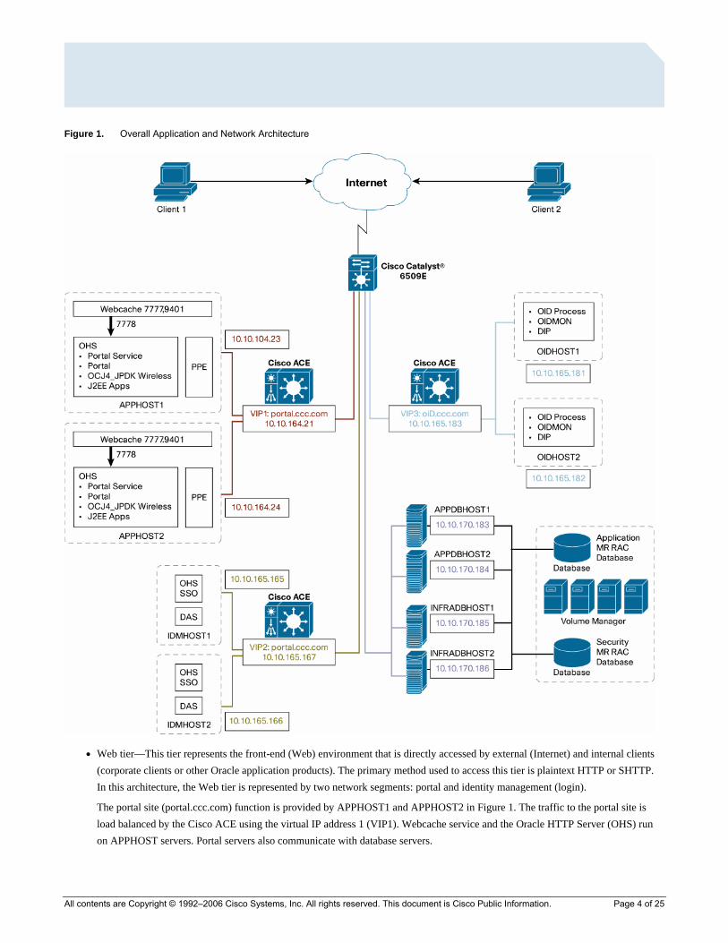
Figure 1. Overall Application and Network Architecture
● Web tier—This tier represents the front-end (Web) environment that is directly accessed by external (Internet) and internal clients (corporate clients or other Oracle application products). The primary method used to access this tier is plaintext HTTP or SHTTP. In this architecture, the Web tier is represented by two network segments: portal and identity management (login).
The portal site (portal.ccc.com) function is provided by APPHOST1 and APPHOST2 in Figure 1. The traffic to the portal site is load balanced by the Cisco ACE using the virtual IP address 1 (VIP1). Webcache service and the Oracle HTTP Server (OHS) run on APPHOST servers. Portal servers also communicate with database servers.
All contents are Copyright © 1992–2006 Cisco Systems, Inc. All rights reserved. This document is Cisco Public Information. Page 4 of 25
All contents are Copyright © 1992–2006 Cisco Systems, Inc. All rights reserved. This document is Cisco Public Information. Page 5 of 25
The identity management (login) function is provided by IDMHOST1 and IDMHOST2 in Figure 1. The traffic to identity management services is load balanced by the Cisco ACE using VIP2. Several application-level services such as OHS, stateful switchover (SSO), etc. are running on IDM host(s). Identity management servers also communicate with Oracle Internet Directory (OID) services and database servers to complete login functions.
Details of the flows to APPHOSTs (portal) and IDMHOSTs (login) are covered in later sections in the document.
Note: Although portal and login functions are deployed in separate network segments in the document, they can be easily merged into a single network segment if needed. In addition, some architecture deployments also isolate Web and application functions in separate segments.
● Application tier—This tier represents OID servers OIDHOST1 and OIDHOST2, which are running Lightweight Directory Access Protocol (LDAP) services in this architecture. Internet clients in the desktop tier do not access OID services directly. Hosts in other tiers such as IDMHOSTs in the Web tier and database servers in the database tier access OID services. The traffic to the OID services is load balanced by the Cisco ACE using VIP3.
● Database tier—This tier contains database servers, which store all the data maintained by the myPortal application. In general, external clients do not communicate with database servers directly, but servers in the application tier and Web tier communicate with database servers in order to process certain client requests. Traffic to database servers is not load balanced by the Cisco ACE in this deployment, so database servers are not shown to be deployed behind the Cisco ACE. High availability and load balancing of the database is provided by the Oracle Resource Availability Confirmation (RAC) implementation. Hosts in this tier include APPDBHOST1 and APPDBHOST2, and INFRADBHost1, and INFRADBHost2.
Application Flows
APPHOST (Portal) Flows The following flows are related to the APPHOST suite of the application server suite:
1. Client to portal VIP
The client on the Internet accesses http://portal.ccc.com (port 80) or https://portal.ccc.com (port 443), which is configured as VIP1: 10.10.164.21 as on the Cisco ACE.
The Cisco ACE load balances the request to one of the available Webcache servers running on APPHOST1 or APPHOST2. When the engine load balances the request, it translates the destination TCP port (from 80 or 443) to port 7777 (Webcache server listening port).
Session persistence (stickiness) based on client source IP address or HTTP cookies are recommended to be configured on the Cisco ACE for this flow.
This flow is marked as “1” in light green in Figure 2.
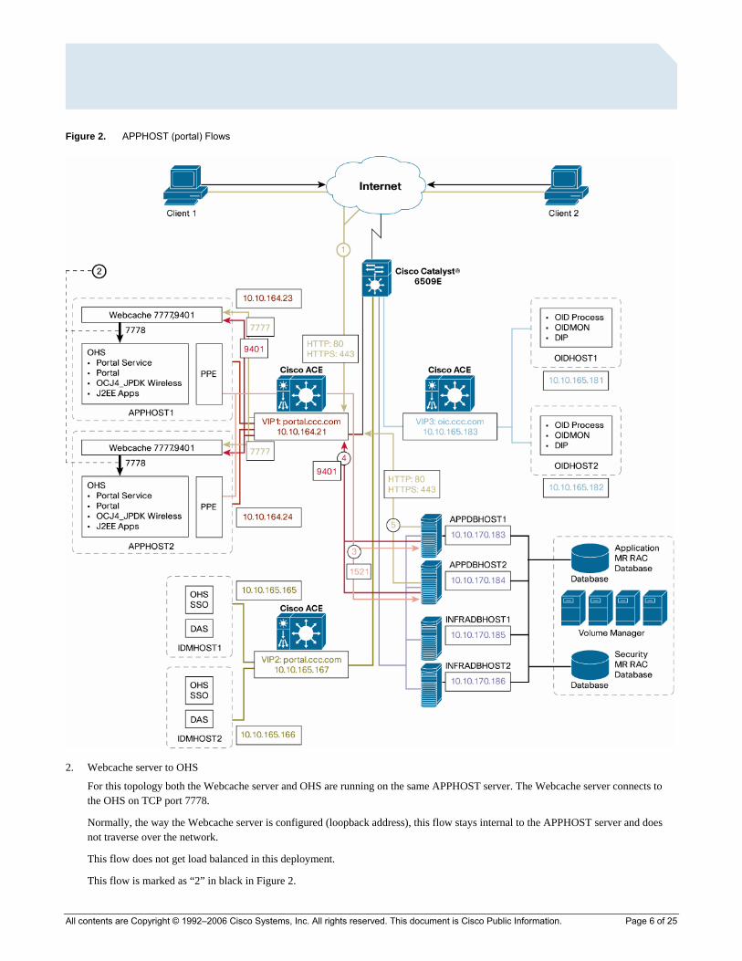
Figure 2. APPHOST (portal) Flows
2. Webcache server to OHS
For this topology both the Webcache server and OHS are running on the same APPHOST server. The Webcache server connects to the OHS on TCP port 7778.
Normally, the way the Webcache server is configured (loopback address), this flow stays internal to the APPHOST server and does not traverse over the network.
This flow does not get load balanced in this deployment.
This flow is marked as “2” in black in Figure 2.
All contents are Copyright © 1992–2006 Cisco Systems, Inc. All rights reserved. This document is Cisco Public Information. Page 6 of 25
All contents are Copyright © 1992–2006 Cisco Systems, Inc. All rights reserved. This document is Cisco Public Information. Page 7 of 25
3. APPHOST to APPDBHOST servers
APPHOST1 and APPHOST2 make database queries to the database server (APPDBHOST1 or APPDBHOST2). For this topology this connection is established on the destination TCP port 1521 (SQL*NET or NET8 as referred to by Oracle) running on the database servers. Some deployments may have this port customized to another TCP port.
This request traverses the network and is routed through the Cisco ACE and the router on the network.
This flow is marked as “3” in pink in Figure 2.
4. Invalidation messages from database to Webcache
The Oracle Application Server Portal Repository (database server in this topology) sends invalidation messages to the Webcache server when content that is cached in the Oracle Application Server Webcache becomes stale.
Webcache servers are listening on TCP port 9401 to receive this message.
This request is an HTTP request made over TCP port 9401 to the virtual IP address 10.10.164.21 on the Cisco ACE by the APPDBHosts.
The Cisco ACE load balances the request to one of the available Webcache servers running on APPHOST1 or APPHOST2.
This flow is marked as “4” in red in Figure 2.
5. JPDK provider registration (from APPDBHOSTs to portal)
This flow is similar to flow 1 except that it is initiated by database hosts APPDBHOST1 and APPDBHOST2. In a multiple middle tier deployment where a load balancer is used, all Java Portal Development Kit (JPDK) applications must be reregistered with the load-balancer router URL.
The database host (APPDBHOST 1 or APPDBHOST2) can access the portal as http://portal.ccc.com/<webApp>/providers/<providername> (port 80), where portal.ccc.com is configured as VIP1: 10.10.164.21on the Cisco ACE.
The Cisco ACE load balances the request to one of the available application hosts—APPHOST1 or APPHOST2. When the Cisco ACE load balances the request, it translates the destination TCP port (from 80 or 443) to port 7777 (APPhost listening port).
Persistence or stickiness based on client source IP address or HTTP cookies is recommended to be configured on the Cisco ACE for this flow.
This flow is marked as “5” in light green in Figure 2.
IDMHOST (Login) Flows 6. Client to login
Clients (on the Internet) are redirected to identity management as http://login.ccc.com (port 80) or https://logic.ccc.com (port 443) if they are not already authenticated. This connection is made to VIP2: 10.10.165.167 on the Cisco ACE.
The Cisco ACE load balances the request to one of the available identity management hosts (IDMHOST1 or IDMHOST2). When the Cisco ACE load balances the request, it translates the destination TCP port (from 80 or 443) to port 7777 (IDMHOST listening port).
Persistence (stickiness) based on client source IP address or HTTP cookies are recommended to be configured on the Cisco ACE for this flow.
This flow is marked as “6” in red in Figure 3.
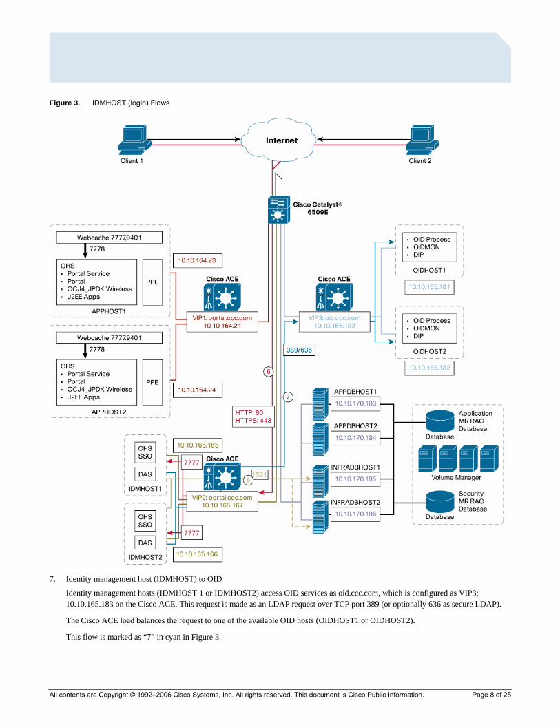
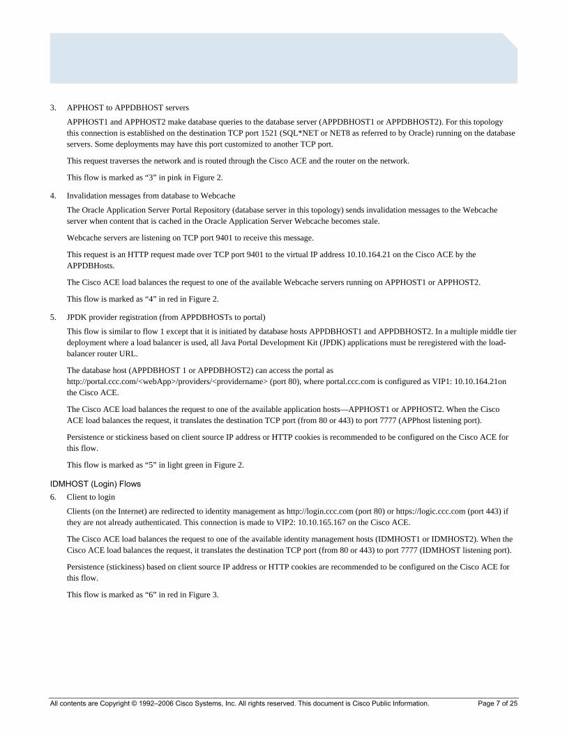
Figure 3. IDMHOST (login) Flows
7. Identity management host (IDMHOST) to OID
Identity management hosts (IDMHOST 1 or IDMHOST2) access OID services as oid.ccc.com, which is configured as VIP3: 10.10.165.183 on the Cisco ACE. This request is made as an LDAP request over TCP port 389 (or optionally 636 as secure LDAP).
The Cisco ACE load balances the request to one of the available OID hosts (OIDHOST1 or OIDHOST2).
This flow is marked as “7” in cyan in Figure 3.
All contents are Copyright © 1992–2006 Cisco Systems, Inc. All rights reserved. This document is Cisco Public Information. Page 8 of 25

All contents are Copyright © 1992–2006 Cisco Systems, Inc. All rights reserved. This document is Cisco Public Information. Page 9 of 25
8. Identity management host (IDMHOST) to database server
IDMHOST1 and IDMHOST2 make database queries to the database server (INFRADBHost1 or INFRADBHost2). For this topology the connection is established on the destination TCP port 1521 (SQL*NET or NET8 as referred to by Oracle) running on the database servers. Some deployment may have this port customized to another TCP port.
This request traverses the network and is routed through the Cisco ACE and router on the network.
This flow is marked as “8” in light green in Figure 3.
OIDhost (LDAP) Flows The following flows are related to the APPHOST suite of the application server suite:
9. Database host (INFRADBHost) to OID
Database hosts (INFRADBHost 1 or INFRADBHost2) access OID services as oid.ccc.com, which is configured as VIP3: 10.10.165.183 on the Cisco ACE. This request is made as an LDAP request over TCP port 389 (or optionally 636 as secure LDAP).
The Cisco ACE load balances the request to one of the available OID hosts (OIDHOST1 or OIDHOST2).
This flow is marked as “9” in light green in Figure 4.
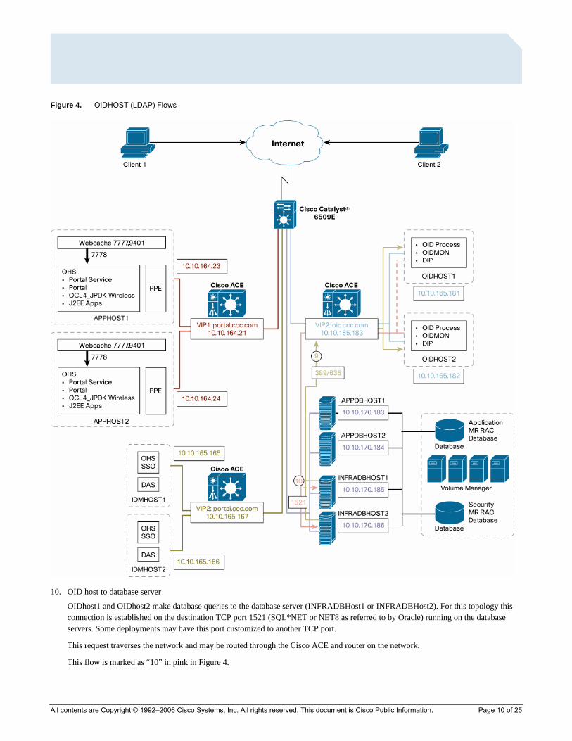
Figure 4. OIDHOST (LDAP) Flows
10. OID host to database server
OIDhost1 and OIDhost2 make database queries to the database server (INFRADBHost1 or INFRADBHost2). For this topology this connection is established on the destination TCP port 1521 (SQL*NET or NET8 as referred to by Oracle) running on the database servers. Some deployments may have this port customized to another TCP port.
This request traverses the network and may be routed through the Cisco ACE and router on the network.
This flow is marked as “10” in pink in Figure 4.
All contents are Copyright © 1992–2006 Cisco Systems, Inc. All rights reserved. This document is Cisco Public Information. Page 10 of 25
NETWORK DESIGN AND CONFIGURATION
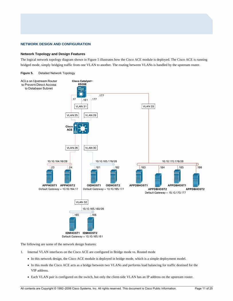
Network Topology and Design Features The logical network topology diagram shown in Figure 5 illustrates how the Cisco ACE module is deployed. The Cisco ACE is running bridged mode, simply bridging traffic from one VLAN to another. The routing between VLANs is handled by the upstream router.
Figure 5. Detailed Network Topology
The following are some of the network design features:
1. Internal VLAN interfaces on the Cisco ACE are configured in Bridge mode vs. Routed mode
● In this network design, the Cisco ACE module is deployed in bridge mode, which is a simple deployment model.
● In this mode the Cisco ACE acts as a bridge between two VLANs and performs load balancing for traffic destined for the VIP address.
● Each VLAN pair is configured on the switch, but only the client-side VLAN has an IP address on the upstream router.
All contents are Copyright © 1992–2006 Cisco Systems, Inc. All rights reserved. This document is Cisco Public Information. Page 11 of 25
All contents are Copyright © 1992–2006 Cisco Systems, Inc. All rights reserved. This document is Cisco Public Information. Page 12 of 25
● The server default gateway is configured to point to the upstream router (Hot Standby Router Protocol [HSRP]) IP address for each client-side VLAN.
● Direct server access is possible if security policy allows.
2. Server segmentation is done through multiple subnets.
● Each functional group of servers is deployed onto its own IP subnet.
● This segmentation provides logical grouping for similar functions and provides easy future expansion.
3. Security is handled by the upstream router and the Cisco ACE module.
● Access lists on the upstream router permit wanted traffic to reach the Cisco ACE and servers directly.
● Access lists are configured on the upstream router to prevent direct access to database servers.
● The Cisco ACE module access lists are configured to allow access to the VIP on application ports.
4. Port translation is handled by the Cisco ACE module.
● The Cisco ACE translates traffic that hits VIP1 and VIP2 on port 80 or 443 to the application port (7777).
5. SSL termination is configured on the Cisco ACE module.
● SSL traffic (port 443) is terminated on the Cisco ACE module, which sends cleartext traffic to application servers on the Webcache services port (7777).
● The client’s source IP address is preserved in this transaction.
● By default, the Cisco ACE can handle up to 1000 SSL transactions per second (tps). For additional performance requirements, additional licenses need to be installed on the Cisco ACE.
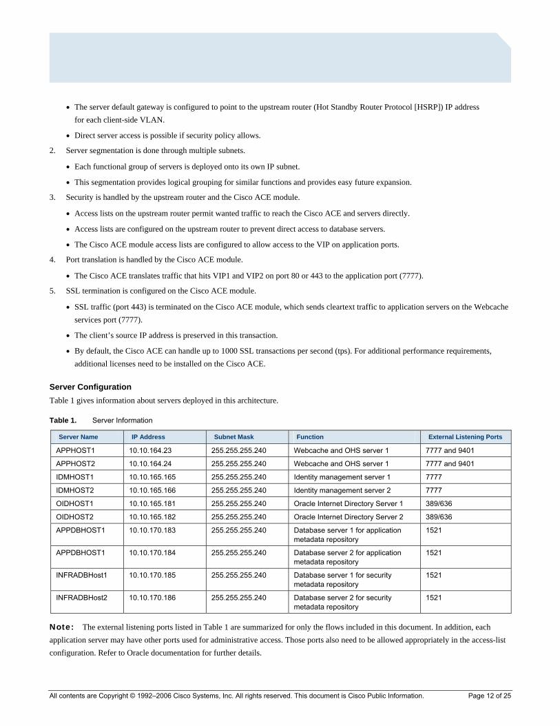
Server Configuration Table 1 gives information about servers deployed in this architecture.
Table 1. Server Information
Server Name IP Address Subnet Mask Function External Listening Ports
APPHOST1 10.10.164.23 255.255.255.240 Webcache and OHS server 1 7777 and 9401
APPHOST2 10.10.164.24 255.255.255.240 Webcache and OHS server 1 7777 and 9401
IDMHOST1 10.10.165.165 255.255.255.240 Identity management server 1 7777
IDMHOST2 10.10.165.166 255.255.255.240 Identity management server 2 7777
OIDHOST1 10.10.165.181 255.255.255.240 Oracle Internet Directory Server 1 389/636
OIDHOST2 10.10.165.182 255.255.255.240 Oracle Internet Directory Server 2 389/636
APPDBHOST1 10.10.170.183 255.255.255.240 Database server 1 for application metadata repository
1521
APPDBHOST1 10.10.170.184 255.255.255.240 Database server 2 for application metadata repository
1521
INFRADBHost1 10.10.170.185 255.255.255.240 Database server 1 for security metadata repository
1521
INFRADBHost2 10.10.170.186 255.255.255.240 Database server 2 for security metadata repository
1521
Note: The external listening ports listed in Table 1 are summarized for only the flows included in this document. In addition, each application server may have other ports used for administrative access. Those ports also need to be allowed appropriately in the access-list configuration. Refer to Oracle documentation for further details.
All contents are Copyright © 1992–2006 Cisco Systems, Inc. All rights reserved. This document is Cisco Public Information. Page 13 of 25
Oracle 10g Application Server Configuration For specific steps to configure Oracle application servers with external hardware load balancers and external SSL termination devices, refer to Chapter 4, “Configuring the Application Infrastructure for myPortalCompany.com” and Appendix A, “Sample Configurations for Certified Load Balancers” in the Oracle document Oracle Application Server Enterprise Deployment Guide 10g Release 2 (10.1.2) for Windows or UNIX with Oracle Part No. B13998-0 provided by Oracle (otn.oracle.com).
Router Configuration The Cisco ACE is installed in a distribution layer Cisco Catalyst® 6509E switch chassis. The Multilayer Switch Feature Card (MSFC) module in the chassis also serves as the upstream router for the Cisco ACE.
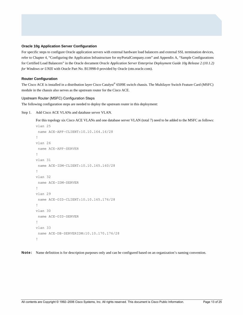
Upstream Router (MSFC) Configuration Steps The following configuration steps are needed to deploy the upstream router in this deployment:
Step 1. Add Cisco ACE VLANs and database server VLAN.
For this topology six Cisco ACE VLANs and one database server VLAN (total 7) need to be added to the MSFC as follows: vlan 25
name ACE-APP-CLIENT:10.10.164.16/28
!
vlan 26
name ACE-APP-SERVER
!
vlan 31
name ACE-IDM-CLIENT:10.10.165.160/28
!
vlan 32
name ACE-IDM-SERVER
!
vlan 29
name ACE-OID-CLIENT:10.10.165.176/28
!
vlan 30
name ACE-OID-SERVER
!
vlan 33
name ACE-DB-SERVERIDM:10.10.170.176/28
!
Note: Name definition is for description purposes only and can be configured based on an organization’s naming convention.

All contents are Copyright © 1992–2006 Cisco Systems, Inc. All rights reserved. This document is Cisco Public Information. Page 14 of 25
Step 2. Permit VLAN traffic to Cisco ACE
The ACE will not accept VLAN traffic unless Cisco Catalyst 6509E switch is specifically configured to allow VLANs to access the ACE module. By not allowing all VLANs to access ACE, broadcast storms on non-ACE VLANs have no effect to the ACE. For this deployment, the Cisco ACE is installed in slot 4 in the Cisco Catalyst 6509E chassis. The following configuration needs to be added to allow Cisco ACE-specific VLAN traffic to be directed toward the Cisco ACE: svclc multiple-vlan-interfaces
svclc module 4 vlan-group 11
svclc vlan-group 11 25,26,29,30,31,32,33
Step 3. Configure the switched virtual interface (SVI) (interface VLAN).
The SVI (interface VLAN) configuration defines the Layer 3 instance on the router (MSFC). For this deployment, four SVIs need to be configured: three Cisco ACE client-side VLAN SVIs and one database server-side VLAN.
The Cisco ACE client-side VLAN SVI configuration follows: interface Vlan25
description ACE-APPSRV-Client-Side
ip address 10.10.164.17 255.255.255.240
no ip redirects
no ip proxy-arp
!
Note: This IP address serves as the default gateway for APPHOST servers and for the Cisco ACE. In a redundant design, this IP address is configured as an HSRP address. Refer to the Cisco HSRP configuration guide for an example: http://www.cisco.com/en/US/tech/tk648/tk362/technologies_tech_note09186a0080094afd.shtml#topic1
interface Vlan31
description ACE-IDMSRV-Client-Side
ip address 10.10.165.171 255.255.255.240
no ip redirects
no ip proxy-arp
!
Note: This IP address serves as the default gateway for IDMHOST servers and for the Cisco ACE. In a redundant design, this IP address is configured as an HSRP address. Refer to the Cisco HSRP configuration guide for an example: http://www.cisco.com/en/US/tech/tk648/tk362/technologies_tech_note09186a0080094afd.shtml#topic1
interface Vlan29
description ACE-OIDSRV-Client-Side
ip address 10.10.165.177 255.255.255.240
no ip redirects
no ip proxy-arp
!
All contents are Copyright © 1992–2006 Cisco Systems, Inc. All rights reserved. This document is Cisco Public Information. Page 15 of 25
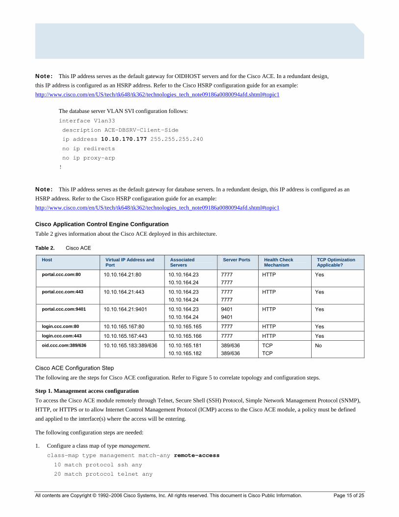
Note: This IP address serves as the default gateway for OIDHOST servers and for the Cisco ACE. In a redundant design, this IP address is configured as an HSRP address. Refer to the Cisco HSRP configuration guide for an example: http://www.cisco.com/en/US/tech/tk648/tk362/technologies_tech_note09186a0080094afd.shtml#topic1
The database server VLAN SVI configuration follows: interface Vlan33
description ACE-DBSRV-Client-Side
ip address 10.10.170.177 255.255.255.240
no ip redirects
no ip proxy-arp
!
Note: This IP address serves as the default gateway for database servers. In a redundant design, this IP address is configured as an HSRP address. Refer to the Cisco HSRP configuration guide for an example: http://www.cisco.com/en/US/tech/tk648/tk362/technologies_tech_note09186a0080094afd.shtml#topic1
Cisco Application Control Engine Configuration Table 2 gives information about the Cisco ACE deployed in this architecture.
Table 2. Cisco ACE
Host Virtual IP Address and Port
Associated Servers
Server Ports Health Check Mechanism
TCP Optimization Applicable?
portal.ccc.com:80 10.10.164.21:80 10.10.164.23 10.10.164.24
7777 7777
HTTP Yes
portal.ccc.com:443 10.10.164.21:443 10.10.164.23 10.10.164.24
7777 7777
HTTP Yes
portal.ccc.com:9401 10.10.164.21:9401 10.10.164.23 10.10.164.24
9401 9401
HTTP Yes
login.ccc.com:80 10.10.165.167:80 10.10.165.165 7777 HTTP Yes
login.ccc.com:443 10.10.165.167:443 10.10.165.166 7777 HTTP Yes
oid.ccc.com:389/636 10.10.165.183:389/636 10.10.165.181 10.10.165.182
389/636 389/636
TCP TCP
No
Cisco ACE Configuration Step The following are the steps for Cisco ACE configuration. Refer to Figure 5 to correlate topology and configuration steps.
Step 1. Management access configuration To access the Cisco ACE module remotely through Telnet, Secure Shell (SSH) Protocol, Simple Network Management Protocol (SNMP), HTTP, or HTTPS or to allow Internet Control Management Protocol (ICMP) access to the Cisco ACE module, a policy must be defined and applied to the interface(s) where the access will be entering.
The following configuration steps are needed:
1. Configure a class map of type management. class-map type management match-any remote-access
10 match protocol ssh any
20 match protocol telnet any
All contents are Copyright © 1992–2006 Cisco Systems, Inc. All rights reserved. This document is Cisco Public Information. Page 16 of 25
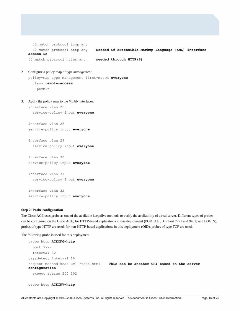
30 match protocol icmp any
40 match protocol http any Needed if Extensible Markup Language (XML) interface access is
50 match protocol https any needed through HTTP(S)
2. Configure a policy map of type management. policy-map type management first-match everyone
class remote-access
permit
3. Apply the policy map to the VLAN interfaces. interface vlan 25
service-policy input everyone
interface vlan 26
service-policy input everyone
interface vlan 29
service-policy input everyone
interface vlan 30
service-policy input everyone
interface vlan 31
service-policy input everyone
interface vlan 32
service-policy input everyone
Step 2: Probe configuration The Cisco ACE uses probe as one of the available keepalive methods to verify the availability of a real server. Different types of probes can be configured on the Cisco ACE; for HTTP-based applications in this deployment (PORTAL [TCP Port 7777 and 9401] and LOGIN), probes of type HTTP are used; for non-HTTP-based applications in this deployment (OID), probes of type TCP are used.
The following probe is used for this deployment:
probe http ACECFG-http
port 7777
interval 30
passdetect interval 10
request method head url /test.html This can be another URI based on the server configuration
expect status 200 202
probe http ACEINV-http

All contents are Copyright © 1992–2006 Cisco Systems, Inc. All rights reserved. This document is Cisco Public Information. Page 17 of 25
port 9401
interval 30
passdetect interval 10
request method head url /test.html This can be another URI based on the server configuration
expect status 200 202
probe tcp OID-probe
port 389
interval 30
passdetect interval 10
Step 3: Rserver configuration The load balancer selects the “real servers” to send the intended traffic based on certain sets of criteria. When configuring an Rserver, be aware that the real server name is case-sensitive. The minimum configuration needed for Rserver configuration is setting the IP address and making the Rserver the in-service server.
The following Rservers are used for this deployment:
rserver host aceapp1
ip address 10.10.164.23
inservice
rserver host aceapp2
ip address 10.10.164.24
inservice
rserver host aceidm1
ip address 10.10.165.165
inservice
rserver host aceidm2
ip address 10.10.165.166
inservice
rserver host aceoid1
ip address 10.10.165.181
inservice
rserver host aceoid2
ip address 10.10.165.182
inservice

All contents are Copyright © 1992–2006 Cisco Systems, Inc. All rights reserved. This document is Cisco Public Information. Page 18 of 25
Step 4: Server farm configuration A server farm is a logical collection of real servers (Rservers) that the load balancer selects based on certain sets of criteria. As with real server, the server farm name is also case-sensitive. Basic server farm configuration includes adding real servers and probes to the server farm.
The following server farms are configured for this deployment:
serverfarm host aceapp
probe ACECFG-http
rserver aceapp1 7777
inservice
rserver aceapp2 7777
inservice
serverfarm host aceinv
probe ACEINV-http
rserver aceapp1 9401
inservice
rserver aceapp2 9401
inservice
serverfarm host aceidm
probe ACECFG-http
rserver aceidm1 7777
inservice
rserver aceidm2 7777
inservice
serverfarm host aceoid
probe OID-probe
rserver aceoid1
inservice
rserver aceoid2
inservice
Step 5: SSL termination configuration SSL termination configuration on the Cisco ACE allows terminating SSL traffic on the engine instead of on the application servers. This setup allows the offloading of server resources, and also allows HTTP request inspection of various load-balancing functions.
The following steps are needed to configure SSL termination on the Cisco ACE:
1. Generate or import the key.
The syntax to generate the key on the Cisco ACE follows:
crypto generate key 1024 <file name>
Example: crypto generate key 1024 testkey
All contents are Copyright © 1992–2006 Cisco Systems, Inc. All rights reserved. This document is Cisco Public Information. Page 19 of 25
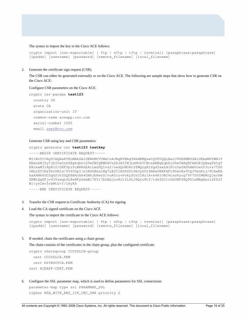
The syntax to import the key to the Cisco ACE follows:
crypto import [non-exportable] [ ftp | sftp | tftp | terminal] [passphrase:passphrase] [ipaddr] [username] [password] [remote_filename] [local_filename]
2. Generate the certificate sign request (CSR).
The CSR can either be generated externally or on the Cisco ACE. The following are sample steps that show how to generate CSR on the Cisco ACE:
Configure CSR parameters on the Cisco ACE:
crypto csr-params test123
country US
state CA
organization-unit IT
common-name aceapp.ccc.com
serial-number 1000
email [email protected]
Generate CSR using key and CSR parameters:
crypto generate csr test123 testkey
-----BEGIN CERTIFICATE REQUEST-----
MIIBnTCCAQYCAQAwXTELMAkGA1UEBhMCVVMxCzAJBgNVBAgTAkNBMQswCQYDVQQLEwJJVDEXMBUGA1UEAxMOYWNlY XBwLmNjYy5jb20xGzAZBgkqhkiG9w0BCQEWDHVzZXJAY2NjLmNvbTCBnzANBgkqhkiG9w0BAQEFAAOBjQAwgYkCgY EA1eaM318pX10/G8FYpi0cBRHdZA1Lxd9Q1vz2/nedQnNOkt0ZWQogH1Zgd5sxLHlPtn5afADhXmVreoY3c+s7TSG vMLLXTIKxTbcURlw/0Y6CGpI/e3ASUBeLtMg7LE2C1EG6ZUL9HJyhUrZNXwOBXFAFL9DwrEx9CQJTmnKzj/8CAwEA AaAAMA0GCSqGSIb3DQEBBAUAA4GBAJbKwzS/vuKhiu+PvEySUzCCHclA+x4KiON26txzKyog7YF7D0ZMKMcQjxrKW ZRWtQgZPjv43Yzwqz4L8w8PyGsmBl7EYi7bOHQjcoKitfL4LJ9Qro8tf/tdn5DC1rGd3BP4XQ9SlxNBgHxzlzFS2f WI/ynCmv5rbMtG+f/LHyKA
-----END CERTIFICATE REQUEST-----
3. Transfer the CSR request to Certificate Authority (CA) for signing
4. Load the CA signed certificate on the Cisco ACE
The syntax to import the certificate to the Cisco ACE follows:
crypto import [non-exportable] [ ftp | sftp | tftp | terminal] [passphrase:passphrase] [ipaddr] [username] [password] [remote_filename] [local_filename]
5. If needed, chain the certificates using a chain group:
The chain consists of the certificates in the chain group, plus the configured certificate.
crypto chaingroup CCCSSLCA-group
cert CCCSSLCA.PEM
cert DSTROOTCA.PEM
cert ACEAPP-CERT.PEM
6. Configure the SSL parameter map, which is used to define parameters for SSL connections: parameter-map type ssl PARAMMAP_SSL
cipher RSA_WITH_AES_128_CBC_SHA priority 2
All contents are Copyright © 1992–2006 Cisco Systems, Inc. All rights reserved. This document is Cisco Public Information. Page 20 of 25
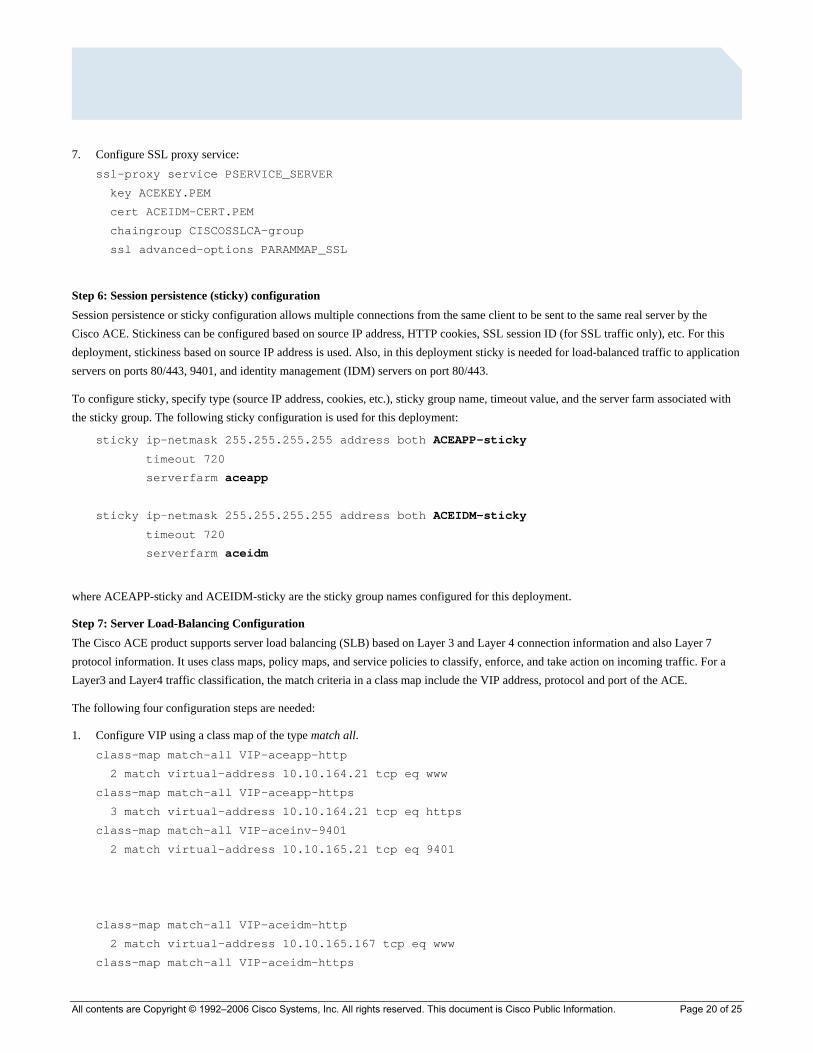
7. Configure SSL proxy service: ssl-proxy service PSERVICE_SERVER
key ACEKEY.PEM
cert ACEIDM-CERT.PEM
chaingroup CISCOSSLCA-group
ssl advanced-options PARAMMAP_SSL
Step 6: Session persistence (sticky) configuration Session persistence or sticky configuration allows multiple connections from the same client to be sent to the same real server by the Cisco ACE. Stickiness can be configured based on source IP address, HTTP cookies, SSL session ID (for SSL traffic only), etc. For this deployment, stickiness based on source IP address is used. Also, in this deployment sticky is needed for load-balanced traffic to application servers on ports 80/443, 9401, and identity management (IDM) servers on port 80/443.
To configure sticky, specify type (source IP address, cookies, etc.), sticky group name, timeout value, and the server farm associated with the sticky group. The following sticky configuration is used for this deployment:
sticky ip-netmask 255.255.255.255 address both ACEAPP-sticky
timeout 720
serverfarm aceapp
sticky ip-netmask 255.255.255.255 address both ACEIDM-sticky
timeout 720
serverfarm aceidm
where ACEAPP-sticky and ACEIDM-sticky are the sticky group names configured for this deployment.
Step 7: Server Load-Balancing Configuration The Cisco ACE product supports server load balancing (SLB) based on Layer 3 and Layer 4 connection information and also Layer 7 protocol information. It uses class maps, policy maps, and service policies to classify, enforce, and take action on incoming traffic. For a Layer3 and Layer4 traffic classification, the match criteria in a class map include the VIP address, protocol and port of the ACE.
The following four configuration steps are needed:
1. Configure VIP using a class map of the type match all. class-map match-all VIP-aceapp-http
2 match virtual-address 10.10.164.21 tcp eq www
class-map match-all VIP-aceapp-https
3 match virtual-address 10.10.164.21 tcp eq https
class-map match-all VIP-aceinv-9401
2 match virtual-address 10.10.165.21 tcp eq 9401
class-map match-all VIP-aceidm-http
2 match virtual-address 10.10.165.167 tcp eq www
class-map match-all VIP-aceidm-https

All contents are Copyright © 1992–2006 Cisco Systems, Inc. All rights reserved. This document is Cisco Public Information. Page 21 of 25
3 match virtual-address 10.10.165.167 tcp eq https
class-map match-all VIP-aceoid
2 match virtual-address 10.10.165.183 tcp eq 389
2. Configure a policy map of the type load balance to associate to a sticky server farm. policy-map type loadbalance first-match vip-lb-ACEAPP
class class-default
sticky-serverfarm ACEAPP-sticky
policy-map type loadbalance first-match vip-lb-ACEINV
class class-default
serverfarm aceinv
policy-map type loadbalance first-match vip-lb-ACEIDM
class class-default
sticky-serverfarm ACEIDM-sticky
policy-map type loadbalance first-match vip-lb-ACEOID
class class-default
serverfarm aceoid
3. Configure policy map of the type multimatch to associate the class map configured in step 1. Also apply the SSL proxy server under class maps for HTTPS traffic. policy-map multi-match lb-vip
class VIP-aceapp-https
loadbalance vip inservice
loadbalance vip-lb-ACEAPP
ssl-proxy server PSERVICE_SERVER
class VIP-aceapp-http
loadbalance vip inservice
loadbalance vip-lb-ACEAPP
class VIP-aceinv-9401
loadbalance vip inservice
loadbalance vip-lb-ACEINV
class VIP-aceidm-https
loadbalance vip inservice
loadbalance vip-lb-ACEIDM
ssl-proxy server PSERVICE_SERVER
class VIP-aceidm-http
loadbalance vip inservice
loadbalance vip-lb-ACEIDM
class VIP-aceoid
loadbalance vip inservice
loadbalance vip-lb-ACEOID
All contents are Copyright © 1992–2006 Cisco Systems, Inc. All rights reserved. This document is Cisco Public Information. Page 22 of 25
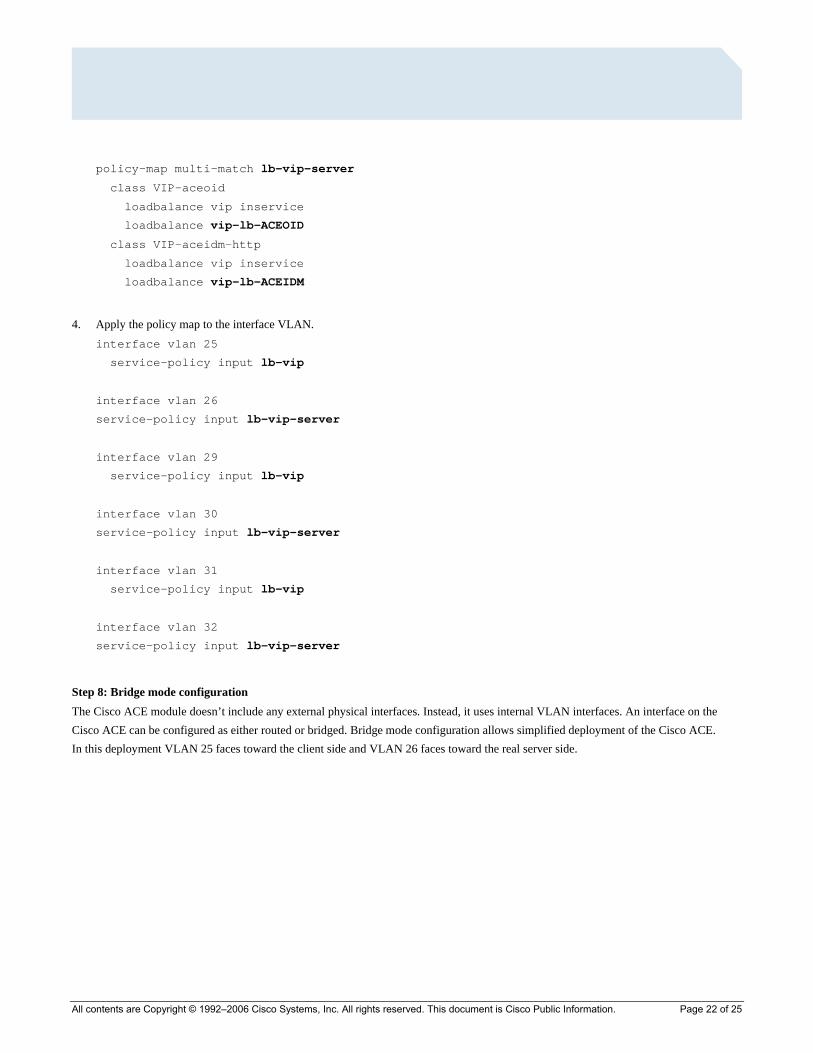
policy-map multi-match lb-vip-server
class VIP-aceoid
loadbalance vip inservice
loadbalance vip-lb-ACEOID
class VIP-aceidm-http
loadbalance vip inservice
loadbalance vip-lb-ACEIDM
4. Apply the policy map to the interface VLAN. interface vlan 25
service-policy input lb-vip
interface vlan 26
service-policy input lb-vip-server
interface vlan 29
service-policy input lb-vip
interface vlan 30
service-policy input lb-vip-server
interface vlan 31
service-policy input lb-vip
interface vlan 32
service-policy input lb-vip-server
Step 8: Bridge mode configuration The Cisco ACE module doesn’t include any external physical interfaces. Instead, it uses internal VLAN interfaces. An interface on the Cisco ACE can be configured as either routed or bridged. Bridge mode configuration allows simplified deployment of the Cisco ACE. In this deployment VLAN 25 faces toward the client side and VLAN 26 faces toward the real server side.

All contents are Copyright © 1992–2006 Cisco Systems, Inc. All rights reserved. This document is Cisco Public Information. Page 23 of 25
The following configuration steps are needed to implement bridge mode configuration on the Cisco ACE:
1. Access-list configuration
An access control list (ACL) must be configured on every interface in order to permit connections. Otherwise, the Cisco ACE denies all traffic on the interface. For this deployment, two access lists named PERMIT_ALL are configured to permit IP and ICMP traffic on interface VLANs. The access list named PERMIT_ALL is assigned for security policies on interface VLAN 25, VLAN 29, and VLAN 31 to allow direct access to real servers; the same access list is also assigned for security policies on interface VLAN 26, VLAN 30, and VLAN 32 in order to permit traffic between real servers and also to access other networks from the real servers. The following configuration permits all IP and ICMP traffic on desired interface VLANs, but Cisco ACE can be easily configured to filter incoming/outgoing traffic on the interface VLANs based on criteria such as source address, destination address, protocol, protocol specific parameters, and so on if required by the Customers.
access-list PERMIT_ALL line 5 extended permit ip any any
access-list PERMIT_ALL line 6 extended permit icmp any any
2. VLAN interfaces configuration
For bridge mode configuration, both client- and server-side VLANs need to be configured. Both VLAN interfaces share a common bridge group. In addition, access lists and a load-balancing service policy are also applied at the interface VLANs.
The following configuration shows the interface VLAN configurations for this deployment, shown in Figure 5:
interface vlan 25
bridge-group 1
access-group input PERMIT_ALL
service-policy input everyone
service-policy input lb-vip
no shutdown
interface vlan 26
bridge-group 1
access-group input PERMIT_ALL
service-policy input everyone
service-policy input lb-vip-server
no shutdown
interface vlan 29
bridge-group 2
access-group input PERMIT_ALL
service-policy input everyone
service-policy input lb-vip
no shutdown
interface vlan 30
bridge-group 2
access-group input PERMIT_ALL
service-policy input everyone
service-policy input lb-vip-server
no shutdown
All contents are Copyright © 1992–2006 Cisco Systems, Inc. All rights reserved. This document is Cisco Public Information. Page 24 of 25
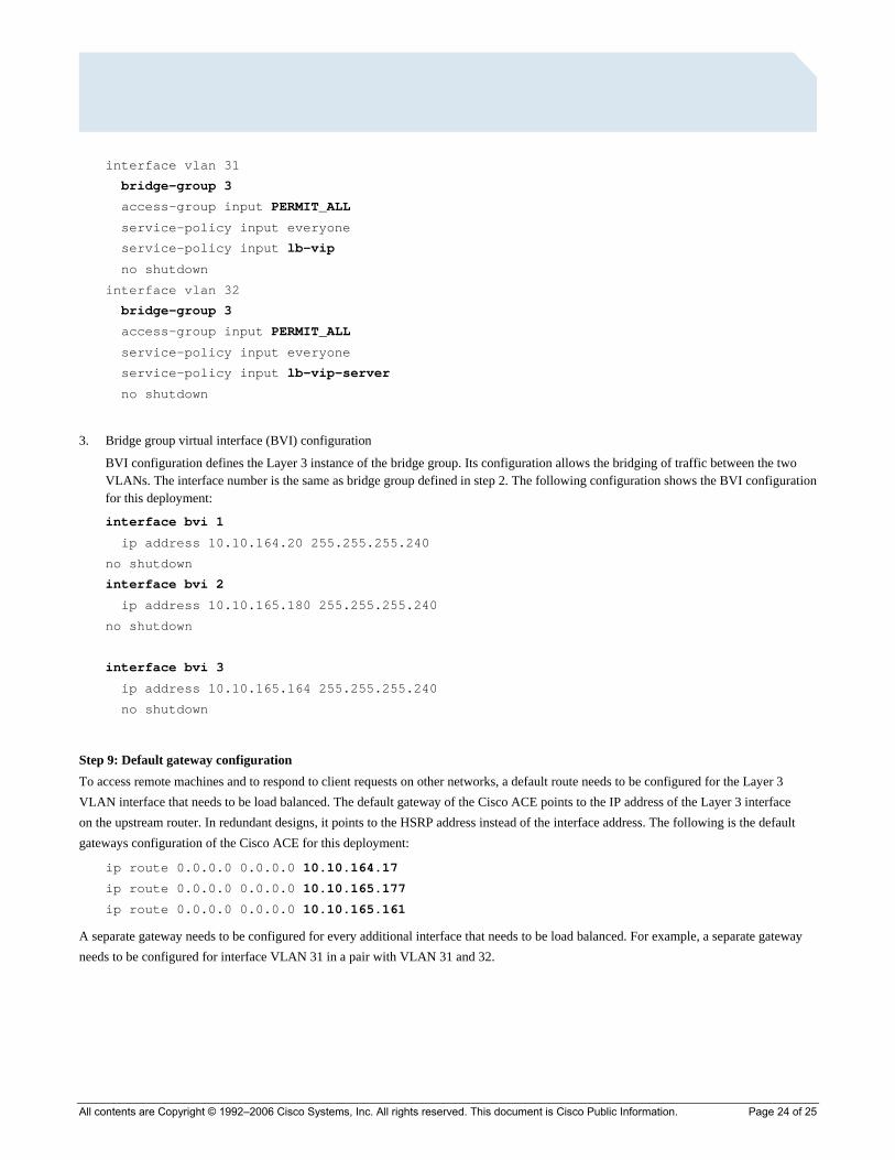
interface vlan 31
bridge-group 3
access-group input PERMIT_ALL
service-policy input everyone
service-policy input lb-vip
no shutdown
interface vlan 32
bridge-group 3
access-group input PERMIT_ALL
service-policy input everyone
service-policy input lb-vip-server
no shutdown
3. Bridge group virtual interface (BVI) configuration
BVI configuration defines the Layer 3 instance of the bridge group. Its configuration allows the bridging of traffic between the two VLANs. The interface number is the same as bridge group defined in step 2. The following configuration shows the BVI configuration for this deployment:
interface bvi 1
ip address 10.10.164.20 255.255.255.240
no shutdown
interface bvi 2
ip address 10.10.165.180 255.255.255.240
no shutdown
interface bvi 3
ip address 10.10.165.164 255.255.255.240
no shutdown
Step 9: Default gateway configuration To access remote machines and to respond to client requests on other networks, a default route needs to be configured for the Layer 3 VLAN interface that needs to be load balanced. The default gateway of the Cisco ACE points to the IP address of the Layer 3 interface on the upstream router. In redundant designs, it points to the HSRP address instead of the interface address. The following is the default gateways configuration of the Cisco ACE for this deployment:
ip route 0.0.0.0 0.0.0.0 10.10.164.17
ip route 0.0.0.0 0.0.0.0 10.10.165.177
ip route 0.0.0.0 0.0.0.0 10.10.165.161
A separate gateway needs to be configured for every additional interface that needs to be load balanced. For example, a separate gateway needs to be configured for interface VLAN 31 in a pair with VLAN 31 and 32.

Printed in USA ETMG_205595.Y_NN_7.06
All contents are Copyright © 1992–2006 Cisco Systems, Inc. All rights reserved. This document is Cisco Public Information. Page 25 of 25