Embed Size (px)
Citation preview
An Oracle White Paper
June 2012
Oracle Real Application Clusters (RAC) and Oracle Clusterware Interconnect Virtual Local Area Networks (VLANs) Deployment Considerations
Oracle RAC and Clusterware Interconnect Virtual Local Area Networks (VLANs)
Executive Overview ........................................................................... 2
Introduction ....................................................................................... 2
Oracle’s Documented Interconnect Deployment Requirements ......... 4
Latency and Bandwidth ..................................................................... 5
Shared Ethernet Switch, VLANs and the Interconnect ....................... 7
Layer 2 Adjacency ......................................................................... 8
Spanning Tree ............................................................................... 8
VLAN Pruning ................................................................................ 9
Consolidation and Converged Networks ...................................... 11
Oversubscription.......................................................................... 11
Conclusion ...................................................................................... 12
Appendix ......................................................................................... 13
A. Spanning Tree Diagnostics .................................................. 13
Oracle RAC and Clusterware Interconnect Virtual Local Area Networks (VLANs)
2
Executive Overview
This paper addresses Oracle’s interconnect requirement as ‘private’ and ‘separate’ and evaluates this
requirement in terms of latency and bandwidth in an shared Ethernet network environment.
A shared Ethernet network, in an Oracle Clusterware interconnect context, is a network where a switch,
network interface or network segment is configured to handle network traffic that is unrelated to the
interconnect traffic. This unrelated traffic may be private interconnect traffic from consolidated databases
or consolidated virtual environments, public traffic from adjacent Local Area Network (LAN) segments,
storage traffic, backup and replication traffic or any other network traffic unrelated to the cluster
interconnect. A shared Ethernet switch network is usually partitioned for broadcast isolation using Virtual
Local Area Networks (VLANs). Partitioning may be configured at the port level on the switch (most
common configuration) for tagged or untagged VLANs depending on the topology. Partitioning may also
occur on the host network adapter using tagged VLANs. A shared Ethernet network implies shared switch
and NIC resources and, as such, are potentially subject to increased contention, performance
degradation and diminished availability.
This paper draws focus to shared Ethernet switch, shared NIC VLAN configuration and deployment
practices intended to optimize for Oracle Clusterware interconnect performance and availability. Oracle
Real Application Clusters (RAC) interconnect latency and bandwidth baselines are described in generic
terms as guidelines and are not intended to apply to Oracle Engineered Systems. These baselines should
be considered when deploying the Oracle Clusterware interconnect in an Shared Ethernet network
topology. The target audience is anyone with an interest in Oracle Clusterware interconnect network
deployment requirements, specifically Architects, DBAs, System Administrators and Network Engineers.
This is paper is not intended to provide specific VLAN configuration guidance but will assist in network
architectural design based on the requirements of the Oracle Clusterware interconnect, variable workload
and the supporting network components.
Introduction
Oracle Clusterware requires a cluster interconnect configured for inter-node communication. This cluster interconnect communication is fundamentally of two types:
1) Inter-node cluster heartbeat and messaging for cluster topology (node and group) management. Inter-node cluster heartbeats and messages tend to be small, ~200 bytes.
2) Inter-node global cache buffer transfers for applications, such as Real Application Clusters (RAC), that exploit active/active inter-node, in-memory buffer access across nodes in the cluster. Inter-node global cache buffer transfers may vary from 2k-16k block sizes depending on the application and the data access patterns.
Oracle RAC and Clusterware Interconnect Virtual Local Area Networks (VLANs)
3
The Oracle Clusterware interconnect is a non-traditional interconnect and should be considered, in shared global cache applications, such as Oracle RAC, to be an I/O subsystem for inter-node global cache buffer transfers with the latency and bandwidth requirements of high performance cluster computing. For this reason, Oracle Clusterware for RAC requires a highly reliable, low-latency, high-bandwidth transport medium to ensure highly available and efficient global cache buffer processing. This requirement traditionally has been satisfied by stand alone, dedicated switches where isolation guarantees control over latency and throughput. To achieve complete isolation and dedicated bandwidth, dedicated switches and NICs are required. In a shared Ethernet network, however, VLANs must be configured to support the cluster interconnect as a private network. VLANs can satisfy the low latency, high bandwidth and network isolation required by the Oracle Clusterware private interconnect. VLAN configurations may vary depending on the desired topology, degree of sharing on the host network interface, the network traffic characteristics and required isolation. This paper describes Oracle interconnect lower bound latency estimates for optimal message and RAC block processing and provides guidelines for conservative bandwidth estimates. These estimates provide a baseline when evaluating actual application runtime latency and throughput requirements and should be measured and evaluated in a shared Ethernet VLAN deployment. The latency, bandwidth and availability requirements of the cluster interconnect require that standard Ethernet design, deployment and monitoring best practices be applied to protect against cluster outages and performance degradation due to common Shared Ethernet switch network events. This paper highlights concern with Spanning Tree events, network congestion due to oversubscribed network segments (switch/NIC), packet broadcast propagation, and VLAN configuration. Footnotes reference network vendor documentation that describes in greater detail Data Center Ethernet network design and deployment best practices relevant to the Oracle Clusterware interconnect performance and availability.
Oracle RAC and Clusterware Interconnect Virtual Local Area Networks (VLANs)
4
Oracle’s Documented Interconnect Deployment Requirements
The Oracle documented requirements for interconnect deployment describe a ‘private’ and ‘separate’ network. The requirements are stated in terms of ‘private’ and ‘separate’ as an isolated network dedicated to interconnect traffic. From Oracle’s documentation:
The interconnect network is a private network using a switch (or multiple switches) that only the nodes in the cluster can access.1
And Oracle Clusterware requires that you connect the nodes in the cluster to a private network by way of a private interconnect. The private interconnect is a separate network that you configure between cluster nodes. The interconnect used by Oracle RAC is the same interconnect that Oracle Clusterware uses. This interconnect should be a private interconnect, meaning it is not accessible to nodes that are not members of the cluster.2
The terms ‘private’ and ‘separate’ have long been interpreted to mean a dedicated, stand-alone switch (or switches for high availability (HA)). For clustered environments that require complete isolation and dedicated bandwidth, this continues to be Oracle’s best practices for interconnect deployment. However, ‘private’ and ‘separate’ dedicated switches do not necessarily correspond to the definitions of latency and bandwidth requirements which are usually needed by the network engineer. And dedicated hardware is contrary to the hardware and software consolidation efforts taking place within the data center.
Currently, the most common Oracle Clusterware interconnect deployments tend to be single gigabit Ethernet (1GbE) links or aggregated/bonded links (an HA best practice), OSI layer 2 adjacency to a switch, e.g. directly attached to a switch or switches. The switch(es) are commonly standalone and provide a dedicated broadcast/multicast domain and non-routed LAN for the interconnect traffic. Consolidation efforts in the datacenter have rendered stand-alone switches unmanageable and contrary to evolving network deployment standards. Increasingly, single gigabit Ethernet is also replaced with 10 gigabit networks to handle the consolidated network load. Motivated by this consolidation and ease of management, network engineers are retiring legacy OSI layer 2 switches for Enterprise Class, multi-layer, managed switches of greater bandwidth capacity. These switches are feature rich and include support for VLANs, variable MTU, link aggregation and Quality of Service. VLANs play a significant role in the network consolidation effort within the datacenter, and, as a consequence, Oracle’s interconnect deployment requirements of ‘private’ and ‘separate’ are evaluated in this context.
1 Oracle® Clusterware Administration and Deployment Guide 11g Release 2 (11.2) Part Number E10717-03 http://download.oracle.com/docs/cd/E14072_01/rac.112/e10717/intro.htm#sthref24 2 Oracle® Database 2 Day + Real Application Clusters Guide11g Release 2 (11.2) Part Number E10743-01
Oracle RAC and Clusterware Interconnect Virtual Local Area Networks (VLANs)
5
Latency and Bandwidth
Oracle Clusterware interconnect latency requirements are reasonably predictable. However, bandwidth requirements may be difficult to calculate prior to deployment. Both latency and bandwidth requirements vary from application to application and are highly dependent on block size, transport media, network stack, hardware (drivers, PCI bus), server cpus (number/speed), interrupt processing, workload (OLTP or DSS) and RDBMS processing efficiencies. Lower bound round trip latencies for Oracle Cache Fusion block processing for UDP single gigabit Ethernet are published and are noted in Table 1 measured in milliseconds for varying block sizes.
Block Size 2K 4K 8K 16K
Round Trip (ms) UDP/1GbE 0.30 0.31 0.36 0.46
Table 1: Oracle Cache Fusion block processing latencies for varying block sizes for UDP on 1GbE
This represents minimum latencies for 2/3-way messaging3. These are lower bound database measured end-to-end latencies, which are optimal, near wire-rate latencies and should be very close to expected values. Upper bound latency is driven by the performance and availability service level requirements of the application with a generous upper bound default latency threshold of 30 seconds. If network messages are not processed within this upper bound threshold, the Oracle Clusterware perceives this as a network fault and may initiate split-brain prevention node fencing. Continued high latency jitter introduces severe performance degradation and may result in cluster packet retransmissions and/or packet loss, which can exacerbate performance problems. High packet processing latencies, and especially sustained high latency, should be thoroughly investigated. As of Oracle Database 11g Release 1, AWR expose interconnect database ping latencies for varying message sizes as depicted in Table 2. These ping latencies are reported as averages with standard deviation for varying database block sizes. The measured latency for a single roundtrip message from the source instance to other instances is measured in milliseconds. The latency of loop back messages from the source instance to itself is used as a control, since message latency can include wait for non-network resources such as memory and CPU. Evaluating these statistics pre-production should give an accurate estimate of latency for the interconnect and for the instance in the environment under test. Regularly monitoring reported latencies should be a common practice for early problem detection, trend analysis and consolidation projections.
3 AWR and Statspack reports would report averages as if they were normally distributed. The session wait history which is included in Statspack in 10.2 and AWR in 11g will show the actual quantities. The minimum values in this table are the optimal values for 2-way and 3-way block transfers, but can be assumed to be the expected values ( i.e., 10ms for a 2-way block would be very high )
Oracle RAC and Clusterware Interconnect Virtual Local Area Networks (VLANs)
6
Target Instance
500B Ping Count
Avg Latency 500B msg
Stddev 500B msg
8K Ping Count
Avg Latency 8K msg
Stddev 8K msg
1 145 1.30 5.07 145 1.30 5.07 2 145 1.01 4.50 145 1.01 4.50 3 145 1.16 4.79 145 1.01 4.50 4 145 1.16 4.79 145 1.16 4.79
Table 2: AWR exposes database interconnect ping latencies in milliseconds for varying message sizes
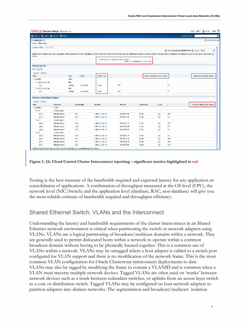
Oracle Clusterware interconnect bandwidth requirements for Ethernet are generally defined by the wire rate of the transport media, which today is commonly 1GbE, and increasingly 10GbE, aggregated for increased bandwidth and/or availability. Bandwidth calculators can only give a course grained estimate of the bandwidth requirement, which is highly dependent on data access patterns in the cluster. Very generally speaking, a 1GbE link saturates at approximately 80-90%, after which, packet loss is likely. For any application or combination of workload, care must be taken to understand the interconnect traffic patterns, peak variation, congestion and potential block loss. The Oracle AWR exposes estimated interconnect traffic4 in kilobytes in the ‘Global Cache Load Profile. Oracle Database 11 Release 2 AWR expose even more statistics related to Global Cache Transfers for CUR and CR buffers for immediate, busy and congested processing as well as interconnect throughput by software component (global cache, parallel query, db locks, db streams and others). The AWR ‘Cache Transfer Statistics’ for Oracle RAC, when evaluated in pre-production testing, provide reliable estimates of interconnect throughput efficiency and a granular breakdown of inter-node block processing per block class 5(data block, undo header, undo block). In addition to AWR, Cloud Control 12c exposes interconnect transfer rates aggregated for the cluster and measured in MB/sec. Cloud Control 12c also provides a breakdown for each node in the cluster, the private network interface total throughput rate and the percentage of total errors on the interface. This data can be displayed graphically or in tabular format covering a specific timeframe6. Figure 1 below is an EM Cloud Control 12c snapshot of the Cluster page reporting Cluster interconnects metrics.
4 see $ORACLE_HOME/rdbms/admin/sprepins.sql for calculation. 5 Transfer statistics aggregated per class is reported only if define variable cache_xfer_per_instance = ‘Y’ 6 See Appendix X for 12c Cloud Control snapshots of Cluster interconnect stats/metrics and threshold alarms.
Oracle RAC and Clusterware Interconnect Virtual Local Area Networks (VLANs)
7
Figure 1: 12c Cloud Control Cluster Interconnect reporting – significant metrics highlighted in red
Testing is the best measure of the bandwidth required and expected latency for any application or consolidation of applications. A combination of throughput measured at the OS level (CPU), the network level (NIC/Switch) and the application level (database, RAC, non-database) will give you the most reliable estimate of bandwidth required and throughput efficiency.
Shared Ethernet Switch, VLANs and the Interconnect
Understanding the latency and bandwidth requirements of the cluster interconnect in an Shared Ethernet network environment is critical when partitioning the switch or network adapters using VLANs. VLANs are a logical partitioning of broadcast/multicast domains within a network. They are generally used to permit dislocated hosts within a network to operate within a common broadcast domain without having to be physically located together. This is a common use of VLANs within a network. VLANs may be untagged where a host adapter is cabled to a switch port configured for VLAN support and there is no modification of the network frame. This is the most common VLAN configuration for Oracle Clusterware interconnect deployments to date. VLANs may also be tagged by modifying the frame to contain a VLANID and is common when a VLAN must traverse multiple network devices. Tagged VLANs are often used on ‘trunks’ between network devices such as a trunk between redundant switches, or uplinks from an access layer switch to a core or distribution switch. Tagged VLANs may be configured on host network adapters to partition adapters into distinct networks. The segmentation and broadcast/multicast isolation
Oracle RAC and Clusterware Interconnect Virtual Local Area Networks (VLANs)
8
provided by VLANs are adequate for interconnect deployment purposes and satisfy the ‘private’ and ‘separate’ network requirements for the cluster interconnect, albeit, with the following caveats:
Layer 2 Adjacency
Servers configured in the Oracle Clusterware must deploy the Oracle Clusterware interconnect as OSI layer 2 adjacent. Servers are considered adjacent when communication with any node in the cluster is in the same broadcast domain and the communication is generally satisfied in a single hop. Each server will be direct attached to the access layer switch or redundant switches. Unlike conventional VLAN configurations, Oracle requires all servers in the cluster to be direct attached to access layer switches. Figure 2 below illustrates the required layer 2 adjacency.
Spanning Tree
The Oracle Clusterware interconnect configured in an Shared Ethernet access switch implies that the switch is participating in a larger bridged Ethernet corporate LAN topology, generally hierarchical, with access, distribution and core switches servicing public, storage, private and management network traffic. The Spanning Tree Protocol (STP) is a network protocol that ensures a loop-free topology for any bridged Ethernet local area network. The basic function of STP is to prevent bridge loops and the broadcast radiation that results from them. Spanning tree also allows a network design to include redundant links to provide automatic backup paths if an active link fails, without the danger of bridge loops, or the need for manual enabling/disabling of these backup links.7 When a network switch or routing device participating in the bridged network fails, a network topology change is detected and is advertised to the entire bridged network. This STP event can flood the network and suspend network packet processing for all devices in the bridged network8. Such an event can interrupt the Oracle Clusterware interconnect traffic causing severe performance degradation and in most cases, clusterware node evictions due to interconnect network failure. STP events should be contained, either by disabling STP for the VLAN or implementing vendor specific STP re-convergence optimizations such as Port Fast definitions, RootGuard, BPDU filtering. Lack of mitigation of STP convergence events can create cluster-wide outages9. Any STP convergence must complete within the Oracle Clusterware heartbeat threshold (30 seconds by default). Some applications have stringent availability Service Level Agreements (SLAs) and will have a more aggressive heartbeat threshold to optimize failure detection. Appendix A illustrates wireshark output for a cluster wide outage triggered by an STP network topology change.
7 Wikipedia, http://en.wikipedia.org/wiki/Spanning_tree_protocol 8 Understanding Spanning-Tree Protocol Topology Changes, Cisco Document ID: 12013 9 Spanning Tree convergence is in function of the number of devices involved and the distance from the STP root and can take greater than Oracle Clusterware default node miscount setting of 30secs. For example Per-VLAN Spanning Tree (PVST), commonly used in inter-switch links (ISL), convergence time can take more than 45 seconds.
Oracle RAC and Clusterware Interconnect Virtual Local Area Networks (VLANs)
9
Note: By default, spanning tree runs on every port. Generally, the spanning tree feature cannot be turned off in switches on a per-port basis. STP can be turned off on a per-VLAN basis, or globally on the switch. Network engineers should coordinate with the appropriate switch vendor for STP best practices.
VLAN Pruning
Switch vendors may provide the ability to extend VLANs between switches through proprietary trunking protocols, such as Cisco’s VTP or VLAN tagging protocols such as Cisco Inter-Switch Links (ISL) and the IEEE 802.1q standard. These features define a VLAN aware network whereby VLAN definitions are propagated on the entire bridged network. This is most often observed when server network redundancy is configured through multi-home (multiple network adapters) configured to redundant access layer switches. Both switches must be aware of the defined VLANs for their network segments and support the use of the appropriate protocol. Figure 2 below illustrates multi-homed servers configured to redundant switches where VLANs are extended between the access layer switches as well as to upstream distribution or core switches. The server network adapters may be VLAN tagged but it is not required in this context. The focus in this use case is the tagged VLANs on the inter-switch link or trunk. VLAN trunking or the use of VLAN tagging is supported for Oracle Clusteware interconnect configuration. Trunks carry traffic from all VLANs to and from switches as all VLANs are active on a trunk link by default. The VLAN trunk or ISL should have the bandwidth capacity to handle all required traffic and not create a bottleneck. VLANs use broadcast and multicast protocols which is replicated over the entire VLAN. All switches in the network where the VLAN is defined would receive all broadcast and multicast communication. To facilitate VLAN configuration in the bridged network, vendor VLAN extensions may automatically propagate VLAN definitions through the bridged network by default. This makes sense for public traffic, however, it is highly discouraged for the Oracle Clusterware private interconnect traffic. VLAN pruning 10 or disabling the clusterware private interconnect VLAN in the trunk should be configured so that private broadcast and multicast traffic does not propagate beyond the access layer11.
10 Understanding VLAN Trunk Protocol (VTP) – VTP Pruning, Cisco Document ID: 10558 11 Access layer switch deployment topologies may vary based on data center deployment standards, where the trunk or ISL is cabled at the access layer (U topology) or, it may be cabled at the distribution layer (inverted U topology) or both (box topology). Please consult your network engineer to determine where VLAN pruning should be enabled.
Oracle RAC and Clusterware Interconnect Virtual Local Area Networks (VLANs)
10
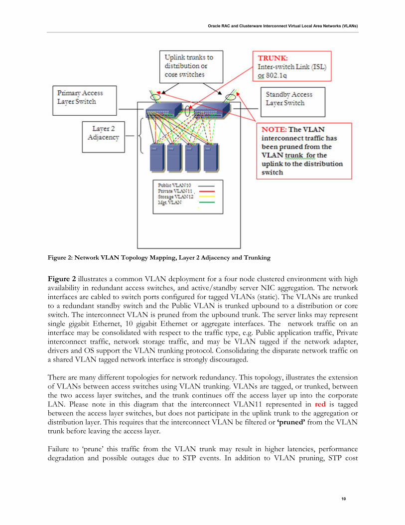
Figure 2: Network VLAN Topology Mapping, Layer 2 Adjacency and Trunking
Figure 2 illustrates a common VLAN deployment for a four node clustered environment with high availability in redundant access switches, and active/standby server NIC aggregation. The network interfaces are cabled to switch ports configured for tagged VLANs (static). The VLANs are trunked to a redundant standby switch and the Public VLAN is trunked upbound to a distribution or core switch. The interconnect VLAN is pruned from the upbound trunk. The server links may represent single gigabit Ethernet, 10 gigabit Ethernet or aggregate interfaces. The network traffic on an interface may be consolidated with respect to the traffic type, e.g. Public application traffic, Private interconnect traffic, network storage traffic, and may be VLAN tagged if the network adapter, drivers and OS support the VLAN trunking protocol. Consolidating the disparate network traffic on a shared VLAN tagged network interface is strongly discouraged. There are many different topologies for network redundancy. This topology, illustrates the extension of VLANs between access switches using VLAN trunking. VLANs are tagged, or trunked, between the two access layer switches, and the trunk continues off the access layer up into the corporate LAN. Please note in this diagram that the interconnect VLAN11 represented in red is tagged between the access layer switches, but does not participate in the uplink trunk to the aggregation or distribution layer. This requires that the interconnect VLAN be filtered or ‘pruned’ from the VLAN trunk before leaving the access layer. Failure to ‘prune’ this traffic from the VLAN trunk may result in higher latencies, performance degradation and possible outages due to STP events. In addition to VLAN pruning, STP cost
Oracle RAC and Clusterware Interconnect Virtual Local Area Networks (VLANs)
11
calculations and port blocking should be configured to eliminate or minimize the impact of STP topology changes.
Consolidation and Converged Networks
Consolidation of RAC databases implies that network traffic can be consolidated. For Oracle Clusterware interconnect deployment, this is entirely possible. Oracle supports consolidation of RAC databases and associated private interconnect traffic on dedicated network adapters. A common consolidation is the simultaneous migration of databases to a RAC environment along with the upgrade of 1GbE network interfaces to 10GbE. The consolidated databases in the RAC environment can share the same network interface. The network interface must respect the same interconnect requirements of a dedicated, non-routed subnet. Just as in 1GbE deployments, the consolidated interconnect may be deployed in a single VLAN. If the environment requires segregated networks for the interconnect, tagged VLANs on the interface are supported for network isolation. A common consequence of network consolidation may be a reduction of required IP subnets and supporting VLANs where like-traffic is consolidated from multiple subnets to a single subnet. A common use case is where consolidated RAC databases in a single cabinet may share a single, non-routed subnet mapped to a single static VLAN on the switch. Even though there may be perceived adequate bandwidth to accommodate further consolidated traffic, there are issues related to performance, security and availability that discourages consolidation of clustered public and private traffic on a single or aggregated interfaces. Field experience indicates that consolidation of network traffic should be restricted to network traffic with similar performance and availability characteristics, e.g. consolidated public, consolidated private, consolidated network storage. As a shared resource, any adverse behavior on the network segment may negatively impact unrelated private communication. Distinct from consolidated networks, vendors are providing converged network solutions which are high bandwidth, low latency network solutions, such as, Fibre Channel over Ethernet (FCoE). These solutions tend to be vendor specific with specialized adapters capable of Fibre Channel encapsulation in an Ethernet frame. Proprietary solutions often provide virtualization of interfaces ( virtual NICs, virtual HBAs and virtual switching), as well as support for Data Center Bridging12 (DCB) protocols for Priority Flow Control, Congestion management and Enhanced Transmission Selection for network bandwidth assignment and management. Certification and support for FCoE solutions are posted on the Oracle Technical Network certification matrix. As Ethernet bandwidth increases, Oracle will evaluate a broader generalization of the DCB framework for larger and more diverse consolidation support.
Oversubscription
RAC IP traffic, and network traffic in an Ethernet environment in general, tends to be bursty in nature and lends itself to oversubscription design. Calculated oversubscription is common in switch configurations, particularly as you move away from the network edge devices. In a shared network
12 See 802.1 Working Group Data Center Bridging Task Group - http://www.ieee802.org/1/pages/dcbridges.html
Oracle RAC and Clusterware Interconnect Virtual Local Area Networks (VLANs)
12
environment for shared switches, ports, network adapters and network segments, careful evaluation of interconnect usage, usage variation and network efficiencies must be regularly evaluated. The consequences of transient oversubscription may be negligible, however, sustained oversubscription of a network device will likely result in degraded performance, a fault of the network device or server and subsequent interruption of service to the business.
Conclusion
Oracle’s interconnect deployment requirements are historically conservative. They are conservative because the consequences of performance degradation or interconnect failure are costly. Oracle requires the interconnect to be configured on a private, dedicated LAN or VLAN (tagged or untagged), which is non-routed and isolated from non-interconnect traffic. Oracle requires the low latency and bandwidth to satisfy the performance and availability requirements of the application. These requirements, should be within the latencies norms described above and not exceed any timeout values configured for the rdbms, or clusterware, mandated by the application, which may trigger instance or node eviction . At a minimum, the application availability and response time (service time) should define the service level agreement (SLA), which, in turn, defines the network requirements. As network technologies evolve to respond to the changing dynamics in the data center, Oracle will continue to evaluate the Oracle Clusterware interconnect requirements.
Oracle RAC and Clusterware Interconnect Virtual Local Area Networks (VLANs)
13
Appendix
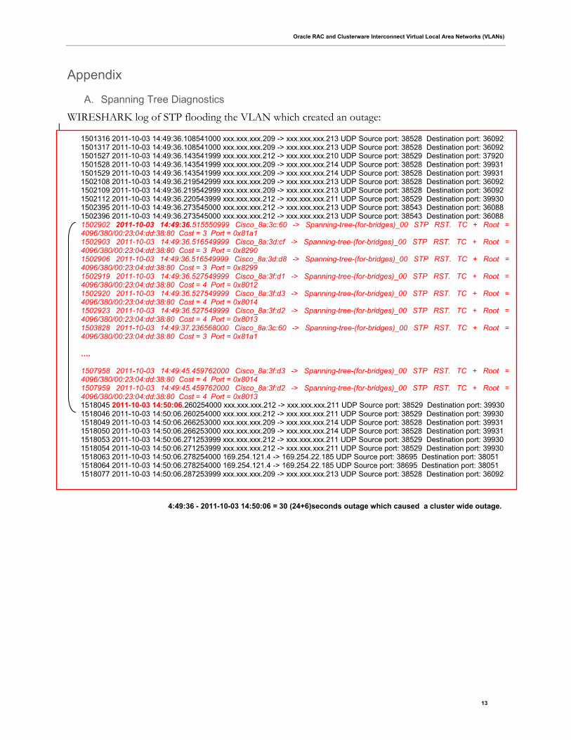
A. Spanning Tree Diagnostics
WIRESHARK log of STP flooding the VLAN which created an outage:
4:49:36 - 2011-10-03 14:50:06 = 30 (24+6)seconds outage which caused a cluster wide outage.
1501316 2011-10-03 14:49:36.108541000 xxx.xxx.xxx.209 -> xxx.xxx.xxx.213 UDP Source port: 38528 Destination port: 36092 1501317 2011-10-03 14:49:36.108541000 xxx.xxx.xxx.209 -> xxx.xxx.xxx.213 UDP Source port: 38528 Destination port: 36092 1501527 2011-10-03 14:49:36.143541999 xxx.xxx.xxx.212 -> xxx.xxx.xxx.210 UDP Source port: 38529 Destination port: 37920 1501528 2011-10-03 14:49:36.143541999 xxx.xxx.xxx.209 -> xxx.xxx.xxx.214 UDP Source port: 38528 Destination port: 39931 1501529 2011-10-03 14:49:36.143541999 xxx.xxx.xxx.209 -> xxx.xxx.xxx.214 UDP Source port: 38528 Destination port: 39931 1502108 2011-10-03 14:49:36.219542999 xxx.xxx.xxx.209 -> xxx.xxx.xxx.213 UDP Source port: 38528 Destination port: 36092 1502109 2011-10-03 14:49:36.219542999 xxx.xxx.xxx.209 -> xxx.xxx.xxx.213 UDP Source port: 38528 Destination port: 36092 1502112 2011-10-03 14:49:36.220543999 xxx.xxx.xxx.212 -> xxx.xxx.xxx.211 UDP Source port: 38529 Destination port: 39930 1502395 2011-10-03 14:49:36.273545000 xxx.xxx.xxx.212 -> xxx.xxx.xxx.213 UDP Source port: 38543 Destination port: 36088 1502396 2011-10-03 14:49:36.273545000 xxx.xxx.xxx.212 -> xxx.xxx.xxx.213 UDP Source port: 38543 Destination port: 36088 1502902 2011-10-03 14:49:36.515550999 Cisco_8a:3c:60 -> Spanning-tree-(for-bridges)_00 STP RST. TC + Root = 4096/380/00:23:04:dd:38:80 Cost = 3 Port = 0x81a1 1502903 2011-10-03 14:49:36.516549999 Cisco_8a:3d:cf -> Spanning-tree-(for-bridges)_00 STP RST. TC + Root = 4096/380/00:23:04:dd:38:80 Cost = 3 Port = 0x8290 1502906 2011-10-03 14:49:36.516549999 Cisco_8a:3d:d8 -> Spanning-tree-(for-bridges)_00 STP RST. TC + Root = 4096/380/00:23:04:dd:38:80 Cost = 3 Port = 0x8299 1502919 2011-10-03 14:49:36.527549999 Cisco_8a:3f:d1 -> Spanning-tree-(for-bridges)_00 STP RST. TC + Root = 4096/380/00:23:04:dd:38:80 Cost = 4 Port = 0x8012 1502920 2011-10-03 14:49:36.527549999 Cisco_8a:3f:d3 -> Spanning-tree-(for-bridges)_00 STP RST. TC + Root = 4096/380/00:23:04:dd:38:80 Cost = 4 Port = 0x8014 1502923 2011-10-03 14:49:36.527549999 Cisco_8a:3f:d2 -> Spanning-tree-(for-bridges)_00 STP RST. TC + Root = 4096/380/00:23:04:dd:38:80 Cost = 4 Port = 0x8013 1503828 2011-10-03 14:49:37.236568000 Cisco_8a:3c:60 -> Spanning-tree-(for-bridges)_00 STP RST. TC + Root = 4096/380/00:23:04:dd:38:80 Cost = 3 Port = 0x81a1 …. 1507958 2011-10-03 14:49:45.459762000 Cisco_8a:3f:d3 -> Spanning-tree-(for-bridges)_00 STP RST. TC + Root = 4096/380/00:23:04:dd:38:80 Cost = 4 Port = 0x8014 1507959 2011-10-03 14:49:45.459762000 Cisco_8a:3f:d2 -> Spanning-tree-(for-bridges)_00 STP RST. TC + Root = 4096/380/00:23:04:dd:38:80 Cost = 4 Port = 0x8013 1518045 2011-10-03 14:50:06.260254000 xxx.xxx.xxx.212 -> xxx.xxx.xxx.211 UDP Source port: 38529 Destination port: 39930 1518046 2011-10-03 14:50:06.260254000 xxx.xxx.xxx.212 -> xxx.xxx.xxx.211 UDP Source port: 38529 Destination port: 39930 1518049 2011-10-03 14:50:06.266253000 xxx.xxx.xxx.209 -> xxx.xxx.xxx.214 UDP Source port: 38528 Destination port: 39931 1518050 2011-10-03 14:50:06.266253000 xxx.xxx.xxx.209 -> xxx.xxx.xxx.214 UDP Source port: 38528 Destination port: 39931 1518053 2011-10-03 14:50:06.271253999 xxx.xxx.xxx.212 -> xxx.xxx.xxx.211 UDP Source port: 38529 Destination port: 39930 1518054 2011-10-03 14:50:06.271253999 xxx.xxx.xxx.212 -> xxx.xxx.xxx.211 UDP Source port: 38529 Destination port: 39930 1518063 2011-10-03 14:50:06.278254000 169.254.121.4 -> 169.254.22.185 UDP Source port: 38695 Destination port: 38051 1518064 2011-10-03 14:50:06.278254000 169.254.121.4 -> 169.254.22.185 UDP Source port: 38695 Destination port: 38051 1518077 2011-10-03 14:50:06.287253999 xxx.xxx.xxx.209 -> xxx.xxx.xxx.213 UDP Source port: 38528 Destination port: 36092
Oracle RAC and Clusterware Interconnect Virtual Local Area Networks (VLANs)
14
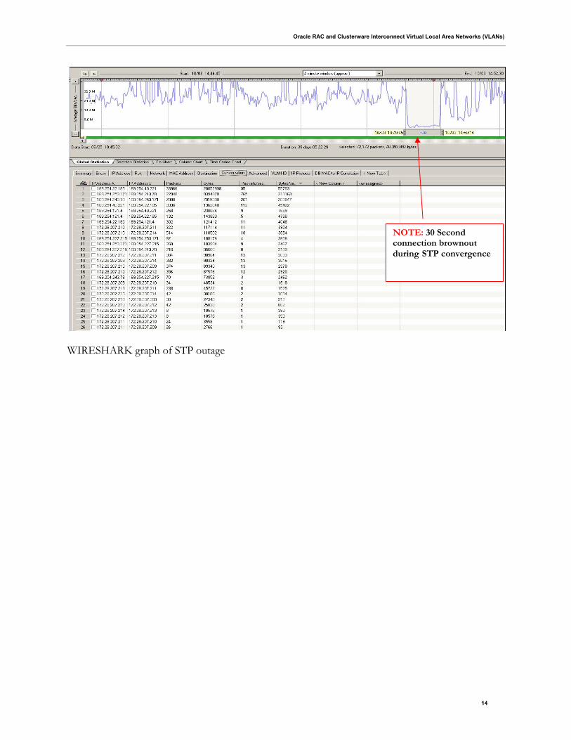
WIRESHARK graph of STP outage
NOTE: 30 Second connection brownout during STP convergence
White Paper Title
June 2012
Author: John P. McHugh
Contributing Authors: Michael Zoll, Kevin
Reardon
Oracle Corporation
World Headquarters
500 Oracle Parkway
Redwood Shores, CA 94065
U.S.A.
Worldwide Inquiries:
Phone: +1.650.506.7000
Fax: +1.650.506.7200
oracle.com
Copyright © 2011, Oracle and/or its affiliates. All rights reserved. This document is provided for information purposes only and the
contents hereof are subject to change without notice. This document is not warranted to be error-free, nor subject to any other
warranties or conditions, whether expressed orally or implied in law, including implied warranties and conditions of merchantability or
fitness for a particular purpose. We specifically disclaim any liability with respect to this document and no contractual obligations are
formed either directly or indirectly by this document. This document may not be reproduced or transmitted in any form or by any
means, electronic or mechanical, for any purpose, without our prior written permission.
Oracle and Java are registered trademarks of Oracle and/or its affiliates. Other names may be trademarks of their respective owners.
AMD, Opteron, the AMD logo, and the AMD Opteron logo are trademarks or registered trademarks of Advanced Micro Devices.
Intel and Intel Xeon are trademarks or registered trademarks of Intel Corporation. All SPARC trademarks are used under license
and are trademarks or registered trademarks of SPARC International, Inc. UNIX is a registered trademark licensed through X/Open
Company, Ltd. 1010