Embed Size (px)
Citation preview
D8X Product Manual
2.5” Hard Disk Drive
January 20, 2016. Rev 2.2 PMD8X 100778771 Rev. E
© 2015 Seagate Technology LLC. All rights reserved. Seagate and Seagate Technology are registered trademarks of Seagate Technology LLC in the United States and/or other countries. SeaTools is either a trademark or registered trademark of Seagate Technology LLC or one of its affiliated companies in the United States and/or other countries. All other trademarks or registered trademarks are the property of their respective owners. When referring to drive capacity, one gigabyte, or GB, equals one billion bytes and one terabyte, or TB, equals one trillion bytes. Your computer’s operating system may use a different standard of measurement and report a lower capacity. In addition, some of the listed capacity is used for formatting and other functions, and thus will not be available for data storage. Actual data rates may vary depending on operating environment and other factors. The export or re-export of hardware or software containing encryption may be regulated by the U.S. Department of Commerce, Bureau of Industry and Security (for more information, visit www.bis.doc.gov), and controlled for import and use outside of the U.S. Seagate reserves the right to change, without notice, product offerings or specifications.
TABLE OF CONTENTS
CHAPTER 1 SCOPE .............................................................................................................................1
1.1 USER DEFINITION ..............................................................................................................................1 1.2 MANUAL ORGANIZATION ..................................................................................................................1 1.3 SATA .................................................................................................................................................2 1.4 REFERENCE ........................................................................................................................................2
CHAPTER 2 DESCRIPTION ..............................................................................................................3
2.1 INTRODUCTION ..................................................................................................................................3 2.2 KEY FEATURES ..................................................................................................................................4 2.3 STANDARDS AND REGULATIONS........................................................................................................5 2.4 HARDWARE REQUIREMENTS.............................................................................................................5
CHAPTER 3 SPECIFICATIONS ........................................................................................................6
3.1 SPECIFICATION SUMMARY ................................................................................................................6 3.2 PHYSICAL SPECIFICATIONS ...............................................................................................................7 3.3 LOGICAL CONFIGURATIONS..............................................................................................................7 3.4 PERFORMANCE SPECIFICATIONS ......................................................................................................8 3.5 POWER CONSUMPTION ......................................................................................................................9 3.6 ENVIRONMENTAL SPECIFICATIONS .................................................................................................10 3.7 RELIABILITY SPECIFICATIONS ........................................................................................................12
CHAPTER 4 INSTALLATION..........................................................................................................13
4.1 SPACE REQUIREMENTS....................................................................................................................13 4.2 UNPACKING INSTRUCTIONS.............................................................................................................14 4.3 MOUNTING .......................................................................................................................................14
4.3.1 Orientation......................................................................................................................15 4.3.2 Ventilation ......................................................................................................................16
4.4 CABLE CONNECTORS.......................................................................................................................16 4.4.1 SATA Connectivity ..........................................................................................................16
4.5 DRIVE INSTALLATION......................................................................................................................21
CHAPTER 5 DISK DRIVE OPERATION........................................................................................22
5.1 HEAD / DISK ASSEMBLY (HDA) ......................................................................................................22 5.1.1 Base Casting Assembly ...................................................................................................22 5.1.2 DC Spindle Motor Assembly...........................................................................................22 5.1.3 Disk Stack Assembly .......................................................................................................24 5.1.4 Head Stack Assembly ......................................................................................................24 5.1.5 Voice Coil Motor and Actuator Latch Assemblies ..........................................................24 5.1.6 Air Filtration System.......................................................................................................24 5.1.7 Load/Unload Mechanism................................................................................................24
5.2 DRIVE ELECTRONICS .......................................................................................................................25 5.2.1 Digital Signal Process and Interface Controller ............................................................25 5.2.2 Disk Controller ...............................................................................................................25
5.2.2.1 The Host Interface Control Block .............................................................................................. 27 5.2.2.2 The Buffer Control Block .......................................................................................................... 27 5.2.2.3 The Disk Control Block ............................................................................................................. 28 5.2.2.4 The Disk LDPC Control Block .................................................................................................. 28 5.2.2.5 Frequency Synthesizer ............................................................................................................... 28 5.2.2.6 Power Management.................................................................................................................... 29
5.2.3 Read/Write IC .................................................................................................................29 5.2.3.1 Time Base Generator.................................................................................................................. 29 5.2.3.2 Automatic Gain Control ............................................................................................................. 29 5.2.3.3 Asymmetry Correction Circuitry (ASC) .................................................................................... 29 5.2.3.4 Analog Anti-Aliasing Low Pass Filter ....................................................................................... 30 5.2.3.5 Analog to Digital Converter (ADC) and FIR ............................................................................. 30
Seagate D8X Product Manual REV 2.2
5.3 SERVO SYSTEM ................................................................................................................................31 5.4 READ AND WRITE OPERATIONS ......................................................................................................31
5.4.1 The Read Channel...........................................................................................................31 5.4.2 The Write Channel ..........................................................................................................32
5.5 FIRMWARE FEATURES .....................................................................................................................32 5.5.1 Read Caching .................................................................................................................32 5.5.2 Write Caching .................................................................................................................33 5.5.3 Defect Management ........................................................................................................34 5.5.4 Automatic Defect Allocation ...........................................................................................34 5.5.5 SMART............................................................................................................................34 5.5.6 APM ...............................................................................................................................34
CHAPTER 6 SATA III INTERFACE ............................................................................... ................35
6.1 INTRODUCTION ................................................................................................................................35 6.1.1 SATA Terminology..................................................................................................... ...35
6.2 PHYSICAL INTERFACE .....................................................................................................................37 6.3 SIGNAL SUMMARY ...........................................................................................................................37
6.3.1 Signal Descriptions.........................................................................................................37 6.3.2 I/O Register - Address ....................................................................................................38 6.3.3 Control Block Register Descriptions ..............................................................................38
6.3.3.1 Alternate Status Register (ex. 3F6h) .......................................................................................... 38 6.3.3.2 Device Control Register (ex. 3F6h)............................................................................................ 39
6.3.4 Command Block Register Descriptions ..........................................................................39 6.3.4.1 Data Register (Ex. 1F0h)............................................................................................................ 39 6.3.4.2 Features Register and Feature Extended Register (Ex. 1F1h) .................................................... 39 6.3.4.3 Sector Number Register and Sector Number Extended Register (Ex. 1F3h) .............................. 39 6.3.4.4 Error Register (Ex. 1F1h) ........................................................................................................... 39 6.3.4.5 Sector Count Register and Sector Count Extended Register (Ex. 1F2h) .................................... 40 6.3.4.6 Cylinder High Register and Cylinder High Extended Register (Ex. 1F5h) ................................ 40 6.3.4.7 Cylinder Low Register and Cylinder Low Extended Register (Ex. 1F4h) .................................. 40 6.3.4.8 Command Register (Ex. 1F7h)................................................................................................... 40 6.3.4.9 Device Register (Ex. 1F6h) ........................................................................................................ 40 6.3.4.10 Status Register (Ex. 1F7h) ......................................................................................................... 41
CHAPTER 7 SATA III FEATURE SET .............................................................................................42
7.1 DEVICE ACTIVITY SIGNAL ..............................................................................................................42 7.2 STAGGERED SPIN-UP DISABLE CONTROL .......................................................................................42 7.3 AUTO-ACTIVATE IN DMA SETUP FIS ............................................................................................42 7.4 NATIVE COMMAND QUEUING (NCQ) .............................................................................................43 7.5 PHY. EVENT COUNTERS ..................................................................................................................43 7.6 SOFTWARE SETTINGS PRESERVATION............................................................................................44 7.7 SATA POWER MANAGEMENT.........................................................................................................44
CHAPTER 8 ATA COMMAND DESCRIPTIONS ..........................................................................45
8.1 COMMAND TABLE............................................................................................................................45 8.2 COMMAND DESCRIPTIONS...............................................................................................................47
8.2.1 Check Power Mode (E5h)...............................................................................................47 8.2.2 Download Micro Code (92h) ..........................................................................................47 8.2.3 Device Configuration Overlay (B1h) ..............................................................................47 8.2.4 Execute Device Diagnostics (90h) ..................................................................................49 8.2.5 Flush Cache (E7h, EAh: extended).................................................................................49 8.2.6 Format Track (50h) ........................................................................................................49 8.2.7 Identify Device (ECh) .....................................................................................................49 8.2.8 Idle (E3h) ........................................................................................................................55 8.2.9 Idle Immediate (E1h) ......................................................................................................55 8.2.10 Initialize Device Parameters (91h) .................................................................................56 8.2.11 NOP (00h).......................................................................................................................56 8.2.12 Read Buffer (E4h) ...........................................................................................................56 8.2.13 Read DMA (C8h, 25h:extended).....................................................................................56
Seagate D8X Product Manual REV 2.2
8.2.14 Read FPDMA Queued (60h)...........................................................................................56 8.2.15 Read Log Extended (2Fh) ...............................................................................................57 8.2.16 Read Long (22h) .............................................................................................................57 8.2.17 Read Multiple Command (C4h, 29h:extended)...............................................................57 8.2.18 Read Native Max Address (F8h, 27h :extended) ............................................................58 8.2.19 Read Sector(s) (20h, 24h: extended)...............................................................................58 8.2.20 Read Verify Sector(s) (40h, 41h :extended) ....................................................................58 8.2.21 Recalibrate (10h) ............................................................................................................59 8.2.22 Security Disable Password (F6h) ...................................................................................59 8.2.23 Security Erase Prepare (F3h) .........................................................................................59 8.2.24 Security Erase Unit (F4h)...............................................................................................59 8.2.25 Security Freeze Lock (F5h).............................................................................................60 8.2.26 Security Set Password (F1h)...........................................................................................60 8.2.27 Security Unlock (F2h).....................................................................................................61 8.2.28 Seek (7xh) .......................................................................................................................61 8.2.29 Set Features (EFh)..........................................................................................................61 8.2.30 Set Max Address (F9h, 37h: extended) ...........................................................................63 8.2.31 Set Multiple Mode (C6h).................................................................................................63 8.2.32 Sleep (E6h) .....................................................................................................................63 8.2.33 Standby (E2h) .................................................................................................................63 8.2.34 SMART (B0h)..................................................................................................................64
8.2.34.1 Smart disable operations (D9h) .................................................................................................. 64 8.2.34.2 Smart enable/disable attribute auto-save (D2h).......................................................................... 64 8.2.34.3 Smart enable operations (D8h) ................................................................................................... 65 8.2.34.4 Smart execute off-line immediate (D4h) .................................................................................... 65 8.2.34.5 Smart read data (D0h) ................................................................................................................ 66 8.2.34.6 SMART read log sector (D5h) ................................................................................................... 72 8.2.34.7 SMART return status (DAh) ...................................................................................................... 72 8.2.34.8 SMART write log sector (D6h) .................................................................................................. 72
8.2.35 Standby (E2h) .................................................................................................................72 8.2.36 Standby Immediate (E0h)................................................................................................72 8.2.37 Write Buffer (E8h) ..........................................................................................................72 8.2.38 Write DMA (CAh, 35h:extended)....................................................................................72 8.2.39 Write FPDMA Queued (61h) ..........................................................................................73 8.2.40 Write Long (32h).............................................................................................................73 8.2.41 Write Multiple Command (C5h, 39h:extended) ..............................................................73 8.2.42 Write Sector(s) (30h, 34h:extended) ...............................................................................74
CHAPTER 9 MAINTENANCE..........................................................................................................75
9.1 GENERAL INFORMATION .................................................................................................................75 9.2 MAINTENANCE PRECAUTIONS ........................................................................................................75 9.3 SERVICE AND REPAIR ......................................................................................................................77
Seagate D8X Product Manual REV 2.2
LIST OF TABLES
Table 3-1 Specifications ............................................................................................................................6 Table 3-2 Physical Specifications ..............................................................................................................7 Table 3-3 Logical Configurations ..............................................................................................................7 Table 3-4 Performance Specifications .......................................................................................................8 Table 3-5 Power consumption ...................................................................................................................9 Table 3-6 Environmental Specifications ...................................................................................................10 Table 3-7 Reliability Specifications.........................................................................................................12 Table 4-1 SATA Connector Pin Definitions ............................................................................................18 Table 7-1 Phy Event Counter Supports....................................................................................................43 Table 8-1 Command Code Parameters ....................................................................................................45 Table 8-2 Device Configuration Overlay Feature Register Values..........................................................47 Table 8-3 Device Configuration Identify data structure ..........................................................................48 Table 8-4 Diagnostic Codes .....................................................................................................................49 Table 8-5 IDENTIFY DEVICE information ...........................................................................................50 Table 8-6 Automatic Standby Timer Periods...........................................................................................55 Table 8-7 Security password content ......................................................................................................59 Table 8-8 Security Erase Unit Password..................................................................................................60 Table 8-9 Security Set Password data content .........................................................................................60 Table 8-10 Identifier and security level bit interaction ............................................................................61 Table 8-11 Set Features Register Definitions ..........................................................................................62 Table 8-12 Transfer Mode Values ...........................................................................................................62 Table 8-13 Set Max Feature Register Values ..........................................................................................63 Table 8-14 SMART Feature Registers Values.........................................................................................64 Table 8-15 Device SMART Data Structure .............................................................................................66 Table 8-16 SMART Attribute Status Flags..............................................................................................68 Table 8-17 SMART Attribute Data List ..................................................................................................69 Table 8-18 Off-line Data Collection Status Values .................................................................................69 Table 8-19 Self-test Execution Status Values ..........................................................................................70
Seagate D8X Product Manual REV 2.2
SCOPE
CHAPTER 1 SCOPE
Welcome to the D8X series of Seagate® hard disk drive. This series of drives consists of the following models: ST500LM027 and ST1000LM044. This chapter provides an overview of the contents of this manual, including the intended user, manual organization, terminology and conventions. In addition, it provides a list of references that might be helpful to the reader.
1.1 User Definition
The D8X product manual is intended for the following readers:
Original Equipment Manufacturers (OEMs) Distributors
1.2 Manual Organization
This manual provides information about installation, principles of operation, and interface command implementation. It is organized into the following chapters:
Chapter 1 - SCOPE
Chapter 2 - DESCRIPTION Chapter 3 - SPECIFICATIONS Chapter 4 - INSTALLATION Chapter 5 - DISK DRIVE OPERATION Chapter 6 - SATA INTERFACE Chapter 7 - MAINTENANCE
In addition, this manual contains a glossary of terms to help you understand important information
Seagate D8X Product Manual REV 2.2 1
SCOPE
1.3 SATA
The ATA (Advanced Technology Attachment) interface which was developed based on the IDE (Integrated Drive Electronics) has been around from 1980’s. As the PC processor speed has improved, so have the data rates of the HDD. The parallel ATA is reaching its limit of 133 MB/s data transfer rate. Serial implementation of ATA (SATA) will allow the data rate to run even faster so the processor will be utilized more efficiently. Serial ATA has been developed to provide the next generation storage interface.
SATA interface replaces 2 inch wide, 40 pin parallel interface connector with 0.25 inch wide 7 pin serial interface connector. The maximum length of the SATA interface cable can be extended to 1 meter (approximately 39 inches) compared to 18 inch of parallel ATA. SATA also allows a data transfer speed of 150 MB/s, 300 MB/s, and 600 MB/s. Even though SATA will not directly interface with Parallel or traditional ATA (PATA) hardware, it is compliant with ATA protocol and therefore software compatible. The cable geometry with smaller footprint connector reduces board space requirements and improves air flow and heat exchange inside computer systems.
SATA uses point to point connection topology and each channel works independently. There is no sharing of interface, master/slave drive configuration, and no master/slave jumper settings. This is different from Parallel ATA (PATA) architecture where 2 drives per port are supported by a shared bus and drives are designated as master or slave drive based on jumper pin or cable selection. Unlike parallel ATA, SATA drives are hot-plug and hot-swappable.
1.4 Reference
For additional information about the AT interface, refer to:
ATA-2 (AT Attachment 2), Revision 3, January, 1995 ATA-3 (Attachment-3 Interface) Revision 7b, 27 January, 1997 ATA-4 (AT Attachment with Packet Interface Extension) Revision 18, 19 August, 1998 ATA-5 (AT Attachment with Packet Interface Extension) Revision 3, 29 February, 2000 ATA-6 (AT Attachment with Packet Interface Extension) Revision 2a, 26 September, 2001 ATA-7 (AT Attachment with Packet Interface Extension) Revision 1, 28 August, 2002 ATA-8 (AT Attachment with Packet Interface Extension) Revision 0, 16 September, 2008
For introduction about SATA interface please refer to:
SATA 1.0 Design Guides, April 5, 2002. (URL: http:// www.serialdata.org retrieved on May 22, 2003) Serial ATA: A comparison with Ultra ATA Technology
(URL: http://www.intel.com retrieved April 18,2003) Serial ATA: High Speed Serialized AT Attachment, Rev. 1.0a, January 7, 2003, Serial Workgroup.
(URL: http://www.serialdata.org retrieved on May 22, 2003) Serial ATA II: Port Multiplier 1.0 Specification, April 29th, 2003. (URL: http://www.serialdata.org retrieved on May 22, 2003) Serial ATA: High Speed Serialized AT Attachment, Rev. 3.2, August 7, 2013, Serial Workgroup.
(URL: http://www.serialdata.org retrieved on August 7, 2013)
Seagate D8X Product Manual REV 2.2 2
DESCRIPTION
CHAPTER 2 DESCRIPTION
This chapter summarizes general functions and key features of the D8X hard disk drive, as well as the standards and regulations they meet.
2.1 Introduction
The Seagate D8X 2.5 inch hard disk drive is high capacity, high performance random access storage device, which uses non-removable 2.5-inch disks as storage media. Each disk incorporates thin film metallic media technology for enhanced performance and reliability. And for each disk surface there is a corresponding movable head actuator assembly to randomly access the data tracks and write or read the user data.
The D8X hard disk drive includes the AT controller embedded in the disk drive PCB electronics. The drive's electrical interface is compatible with all mandatory, optional and vendor-specific commands within the ATA specification. Drive size conforms to the industry standard 2.5-inch form factor with a SATA 15-pin DC power connector, and the standard SATA 7-pin Interface connector. The D8X hard disk drive incorporates TuMR head and Noise Predictive PRML (Partial Response Maximum Likelihood) signal processing technologies. These advanced technologies allow for areal density of about 677 Gigabits per square inch and storage capacity of over 500.0 Gigabytes per disk. The heads, disk(s), and actuator housing are environmentally sealed within an aluminum-alloy base and cover. As the disks spin, air circulates within this base and cover, commonly referred to as the head and disk assembly (HDA), through a non-replaceable absolute filter ensuring a contamination free environment for the heads and disks throughout the life of the drive.
Seagate D8X Product Manual REV 2.2 3
DESCRIPTION
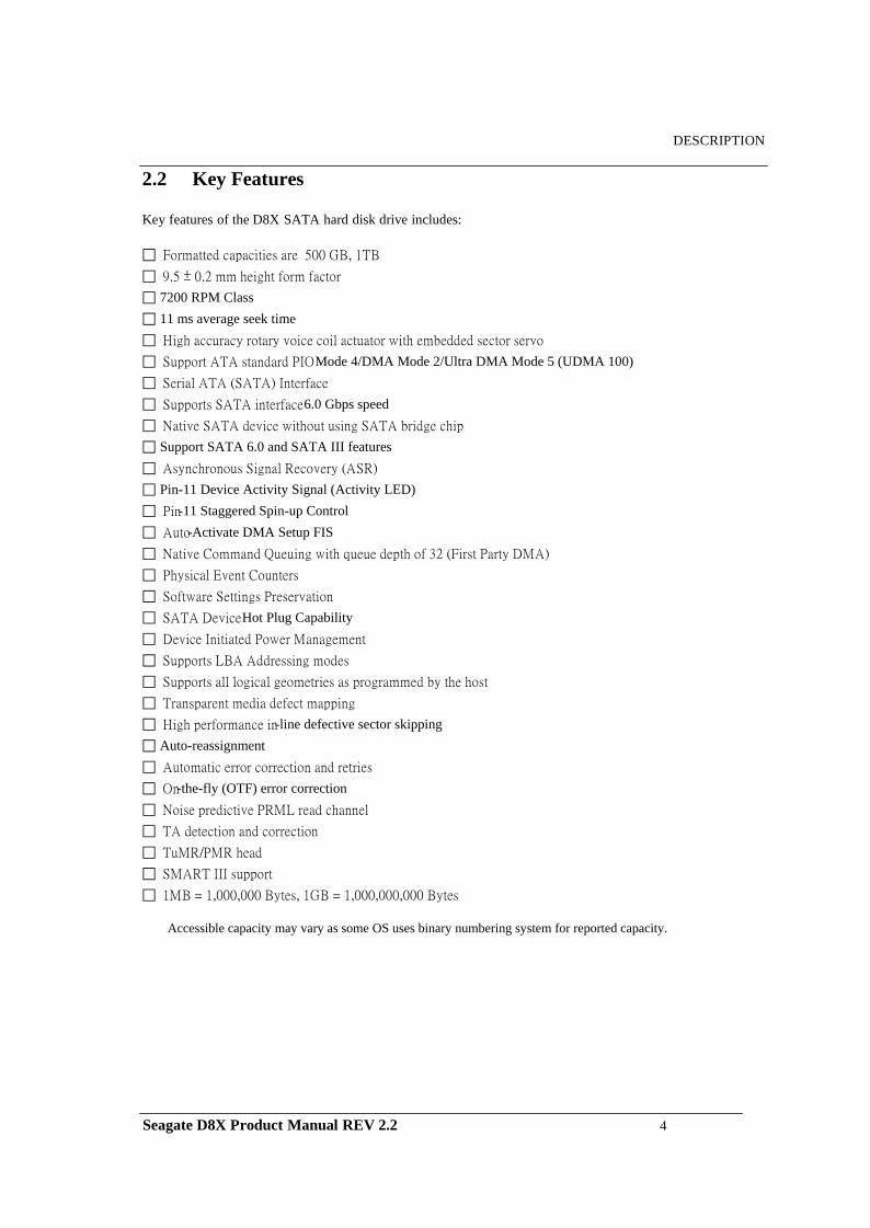
2.2 Key Features
Key features of the D8X SATA hard disk drive includes:
Formatted capacities are 500 GB, 1TB 9.5 ± 0.2 mm height form factor 7200 RPM Class 11 ms average seek time High accuracy rotary voice coil actuator with embedded sector servo Support ATA standard PIO Mode 4/DMA Mode 2/Ultra DMA Mode 5 (UDMA 100) Serial ATA (SATA) Interface Supports SATA interface 6.0 Gbps speed Native SATA device without using SATA bridge chip Support SATA 6.0 and SATA III features Asynchronous Signal Recovery (ASR) Pin-11 Device Activity Signal (Activity LED) Pin-11 Staggered Spin-up Control Auto-Activate DMA Setup FIS Native Command Queuing with queue depth of 32 (First Party DMA) Physical Event Counters Software Settings Preservation SATA Device Hot Plug Capability Device Initiated Power Management Supports LBA Addressing modes Supports all logical geometries as programmed by the host Transparent media defect mapping High performance in-line defective sector skipping Auto-reassignment Automatic error correction and retries On-the-fly (OTF) error correction Noise predictive PRML read channel TA detection and correction TuMR/PMR head SMART III support 1MB = 1,000,000 Bytes, 1GB = 1,000,000,000 Bytes
Accessible capacity may vary as some OS uses binary numbering system for reported capacity.
Seagate D8X Product Manual REV 2.2 4
DESCRIPTION
2.3 Standards and Regulations
The Seagate D8X hard disk drive depends upon its host equipment to provide power and appropriate environmental conditions to achieve optimum performance and compliance with applicable industry and governmental regulations. Special attention has been given in the areas of safety, power distribution, shielding, audible noise control, and temperature regulation.
The D8X hard disk drive satisfies the following standards and regulations:
Underwriters Laboratory (UL): Standard 1950. Information technology equipment including business
equipment. Technisher Überwachungs Verein (TUV): Standard EN 60 950. Information technology equipment
including business equipment.
2.4 Hardware Requirements
The D8X hard disk drive is designed for use with host computers and controllers that are ATA compatible. It is connected to a PC either by:
Using an adapter board with SATA interface, or Plugging a cable from the drive directly into a PC motherboard with a SATA interface
Seagate D8X Product Manual REV 2.2 5
SPECIFICATIONS
CHAPTER 3 SPECIFICATIONS
This chapter gives a detail description of the physical, electrical and environmental characteristics of the D8X hard disk drive.
3.1 Specification Summary
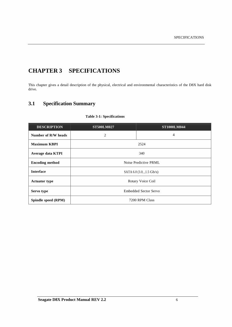
Table 3-1: Specifications
DESCRIPTION ST500LM027 ST1000LM044
Number of R/W heads 2 4
Maximum KBPI 2524
Average data KTPI 340
Encoding method Noise Predictive PRML
Interface SATA 6.0 (3.0, ,1.5 Gb/s)
Actuator type Rotary Voice Coil
Servo type Embedded Sector Servo
Spindle speed (RPM) 7200 RPM Class
Seagate D8X Product Manual REV 2.2 6
SPECIFICATIONS
3.2 Physical Specifications
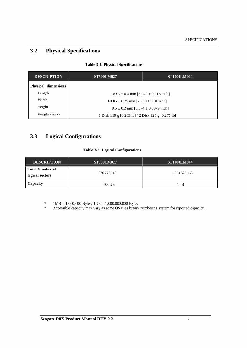
Table 3-2: Physical Specifications
DESCRIPTION ST500LM027 ST1000LM044 Physical dimensions
Length
Width
Height
Weight (max)
100.3 ± 0.4 mm [3.949 ± 0.016 inch]
69.85 ± 0.25 mm [2.750 ± 0.01 inch]
9.5 ± 0.2 mm [0.374 ± 0.0079 inch]
1 Disk 119 g [0.263 lb] / 2 Disk 125 g [0.276 lb]
3.3 Logical Configurations
Table 3-3: Logical Configurations
* 1MB = 1,000,000 Bytes, 1GB = 1,000,000,000 Bytes * Accessible capacity may vary as some OS uses binary numbering system for reported capacity.
DESCRIPTION ST500LM027 ST1000LM044
Total Number of logical sectors
976,773,168 1,953,525,168
Capacity 500GB 1TB
Seagate D8X Product Manual REV 2.2 7
SPECIFICATIONS
3.4 Performance Specifications
Table 3-4: Performance Specifications
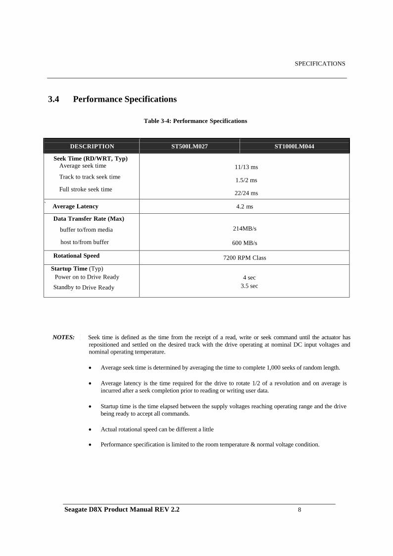
NOTES: Seek time is defined as the time from the receipt of a read, write or seek command until the actuator has repositioned and settled on the desired track with the drive operating at nominal DC input voltages and nominal operating temperature.
• Average seek time is determined by averaging the time to complete 1,000 seeks of random length.
• Average latency is the time required for the drive to rotate 1/2 of a revolution and on average is
incurred after a seek completion prior to reading or writing user data.
• Startup time is the time elapsed between the supply voltages reaching operating range and the drive being ready to accept all commands.
• Actual rotational speed can be different a little
• Performance specification is limited to the room temperature & normal voltage condition.
DESCRIPTION ST500LM027 ST1000LM044
Seek Time (RD/WRT, Typ) Average seek time
Track to track seek time
Full stroke seek time
11/13 ms
1.5/2 ms
22/24 ms
` Average Latency 4.2 ms
Data Transfer Rate (Max)
buffer to/from media
host to/from buffer
214MB/s
600 MB/s
Rotational Speed 7200 RPM Class
Startup Time (Typ) Power on to Drive Ready Standby to Drive Ready
4 sec 3.5 sec
Seagate D8X Product Manual REV 2.2 8
SPECIFICATIONS
3.5 Power consumption
Table 3-5: Power consumption
DESCRIPTION ST500LM027 ST1000LM044
Rated Voltage V +5
Current A 0.85
Power Consumption
Start Up
mA
1000
Low Power Idle
Watt
0.85
Read/Write
Watt
3.5
Seek
Watt
2.2
Stand by
Watt
0.18
Sleep
Watt
0.18
Power Requirements
Tolerance For + 5V
%
+/- 5
Ripple, 0-30MHz
mVp-p
100
Supply Rise Time us/
msec
10us-100ms
Supply Fall Time
Sec
< 5
1) Random seek: 30% Duty cycle seek commands with logical random location.
2) Read/Write: Avg. Read/Write operation at OD for 256 sectors.
3) All the power should be measured at the room temperature and normal voltage condition.
Seagate D8X Product Manual REV 2.2 9
SPECIFICATIONS
3.6 Environmental Specifications Table 3-6: Environmental Specifications
DESCRIPTION ST500LM027 ST1000LM044 Ambient Temperature
Operating
Non-operating
Max. gradient (Temperature/Humidity)
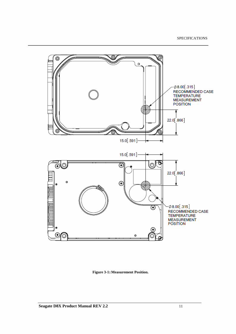
(Drive temperature measured on position of figure 3-1 should be max 70°C in range of 0°C -60°C, specified operation temperature.)
0°C ~ 60°C -40°C ~ 70°C 20°C / 20%/hr
Relative Humidity (non condensing)
Operation
Non-operation
Maximum wet bulb temperature
Operating
Non-operating
5~90 % 5~95 % 30°C 40°C
Altitude (relative to sea level)
Operating
Non-operating
-300 ~ 3000 m -400 ~ 15,000 m
Vibration
Operating :
10-500 Hz, Random
Non-operating :
10-500 Hz, Random
1.5 Grms 5.85 Grms
Linear Shock (1/2 sine pulse)
Operating 2.0 ms
Non-operating 2.0 ms
Rotational Shock
Operating 2.0 ms
Non-operating 2.0 ms
325G
900G 3K rad/sec 2
30K rad/sec 2 Acoustic Noise
(Typical Sound Power)
Idle
Seek
2.7 Bels 2.9 Bels
Seagate D8X Product Manual REV 2.2 10
SPECIFICATIONS
Figure 3-1: Measurement Position.
Seagate D8X Product Manual REV 2.2 11
SPECIFICATIONS
3.7 Reliability Specifications
Table 3-7: Reliability Specifications
DESCRIPTION ST500LM027 ST1000LM044 Recoverable Read Error
<10 in 1011 bits
Non-Recoverable Read Error
<1 sector in 1014 bits MTBF (POH)
550,000 hours
MTTR (Typical)
5 minutes
Load/Unload Cycles
Ambient
600,000
Seagate D8X Product Manual REV 2.2 12
INSTALLATION
CHAPTER 4 INSTALLATION
This chapter describes how to unpack, mount, configure and connect a D8X hard disk drive. It also describes how to install the drive in systems.
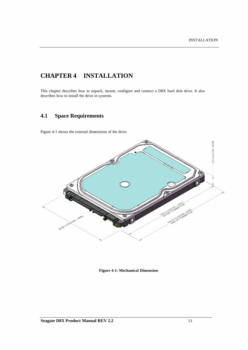
4.1 Space Requirements
Figure 4-1 shows the external dimensions of the drive.
Figure 4-1: Mechanical Dimension
Seagate D8X Product Manual REV 2.2 13
INSTALLATION
4.2 Unpacking Instructions
(1) Open the shipping container of the D8X hard disk drive.
(2) Lift the packing assembly that contains the drive out of the shipping container.
(3) Remove the drive from the packing assembly. When you are ready to install the drive, remove it from the ESD (Electro Static Discharge) protection bag. Take precautions to protect the drive from ESD damage after removing it from the bag.
CAUTION: During shipment and handling, the anti-static ESD protection bag prevents electronic component damage due to electrostatic discharge. To avoid accidental damage to the drive, do not use a sharp instrument to open the ESD protection bag.
(4) Save the packing material for possible future use.
4.3 Mounting
Refer to your system manual for complete mounting details.
(1) Be sure that the system power is off.
(2) For mounting, use four M3 screws.
CAUTION: Torque applied to the screws is recommended to be 3.5 [kg* cm] ±0.5 (3.0 [inch *pounds] ± 0.5)
Seagate D8X Product Manual REV 2.2 14
INSTALLATION
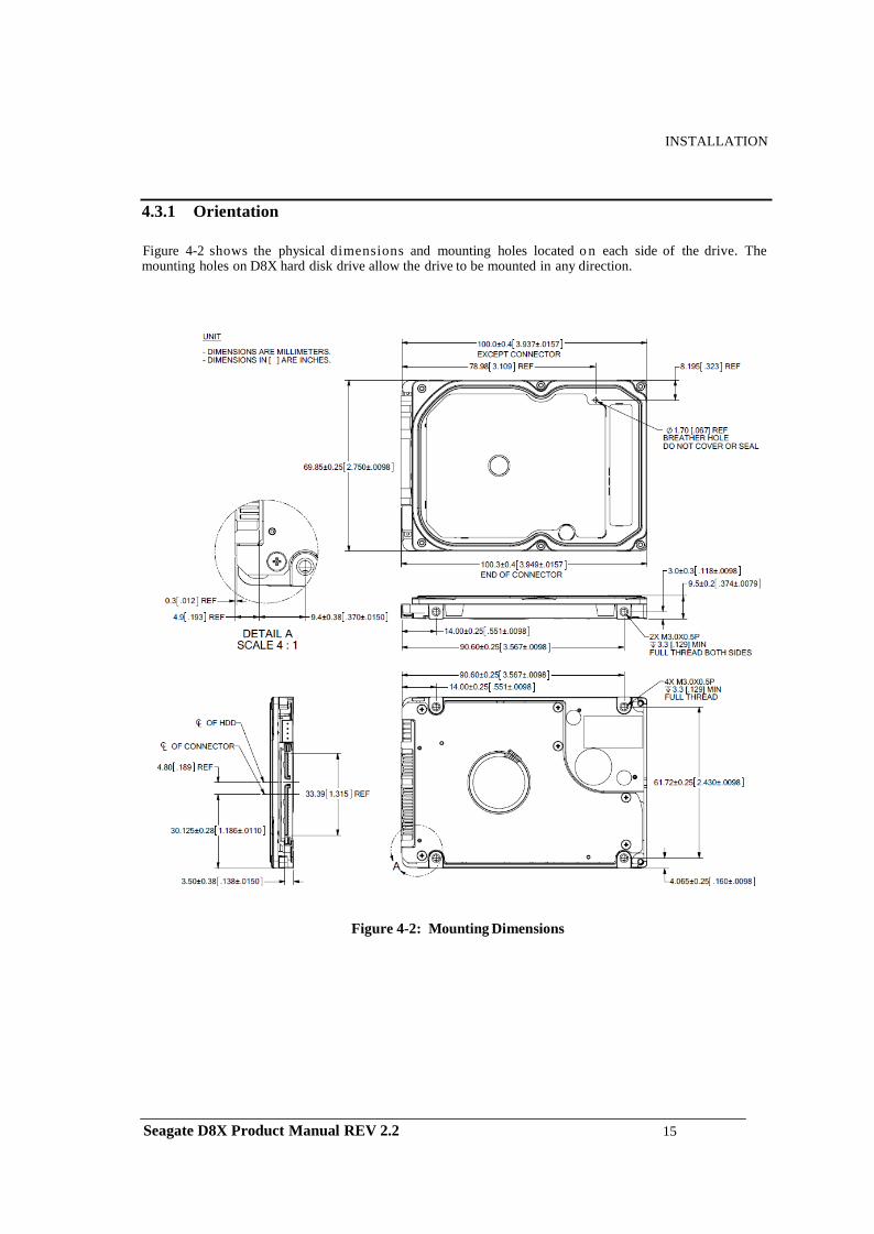
4.3.1 Orientation
Figure 4-2 shows the physical dimensions and mounting holes located o n each side of the drive. The mounting holes on D8X hard disk drive allow the drive to be mounted in any direction.
Figure 4-2: Mounting Dimensions
Seagate D8X Product Manual REV 2.2 15
INSTALLATION 4.3.2 Ventilation
The D8X hard disk drive is designed to operate without the need of a cooling fan provided the ambient air temperature does not exceed 60ºC. Any user-designed cabinet must provide adequate air circulation to prevent exceeding the maximum temperature.
4.4 Cable Connectors
The Interface/Power connector consists of two cables; a SATA 15-pin DC power connector, and the standard SATA 7-pin Interface connector.
4.4.1 SATA Connectivity
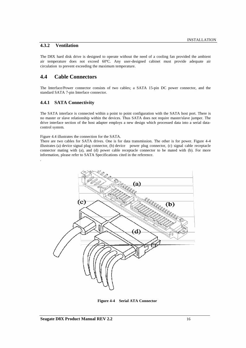
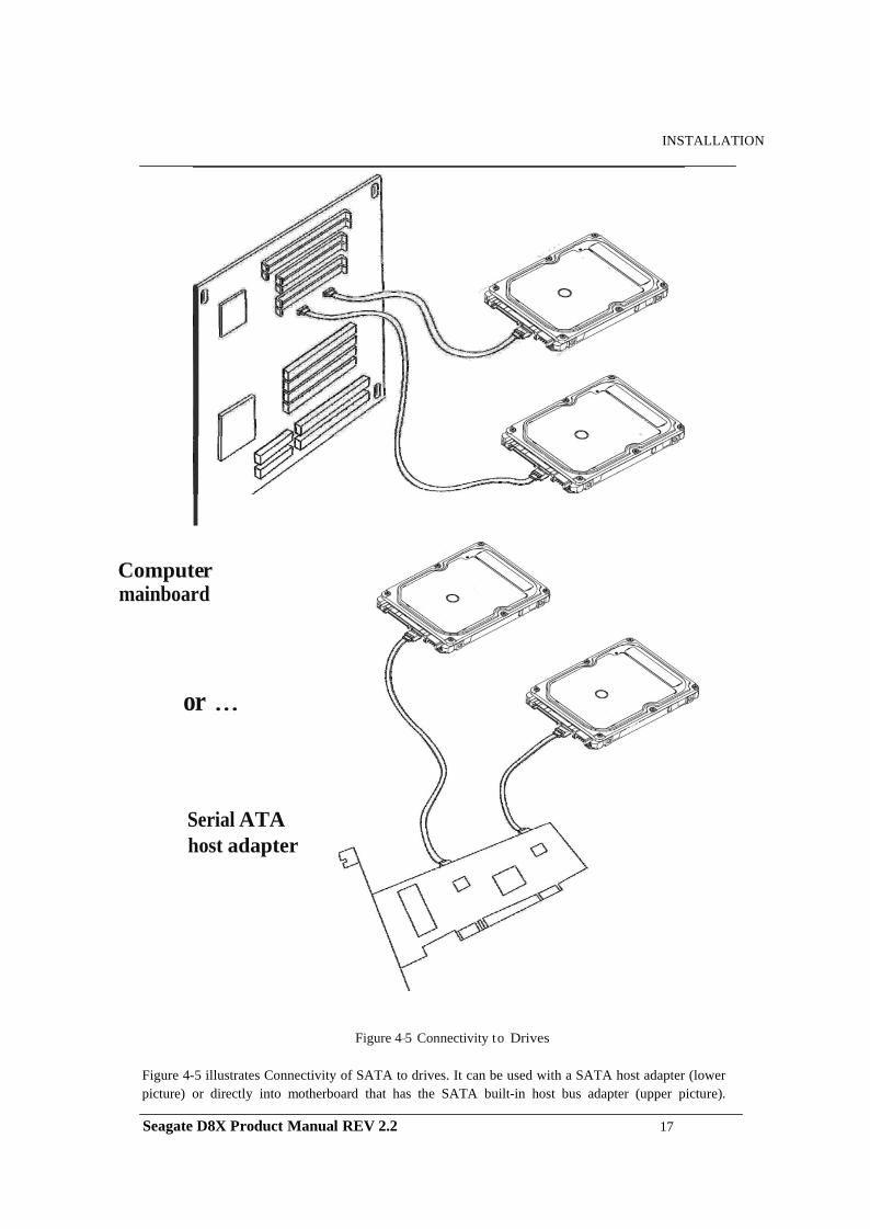
The SATA interface is connected within a point to point configuration with the SATA host port. There is no master or slave relationship within the devices. Thus SATA does not require master/slave jumper. The drive interface section of the host adapter employs a new design which processed data into a serial data-control system.
Figure 4.4 illustrates the connection for the SATA. There are two cables for SATA drives. One is for data transmission. The other is for power. Figure 4-4 illustrates (a) device signal plug connector, (b) device power plug connector, (c) signal cable receptacle connector mating with (a), and (d) power cable receptacle connector to be mated with (b). For more information, please refer to SATA Specifications cited in the reference. .
Figure 4-4 Serial ATA Connector
Seagate D8X Product Manual REV 2.2 16
INSTALLATION
Computer mainboard
or ...
Serial ATA host adapter
Figure 4-5 Connectivity to Drives
Figure 4-5 illustrates Connectivity of SATA to drives. It can be used with a SATA host adapter (lower picture) or directly into motherboard that has the SATA built-in host bus adapter (upper picture).
Seagate D8X Product Manual REV 2.2 17
INSTALLATION
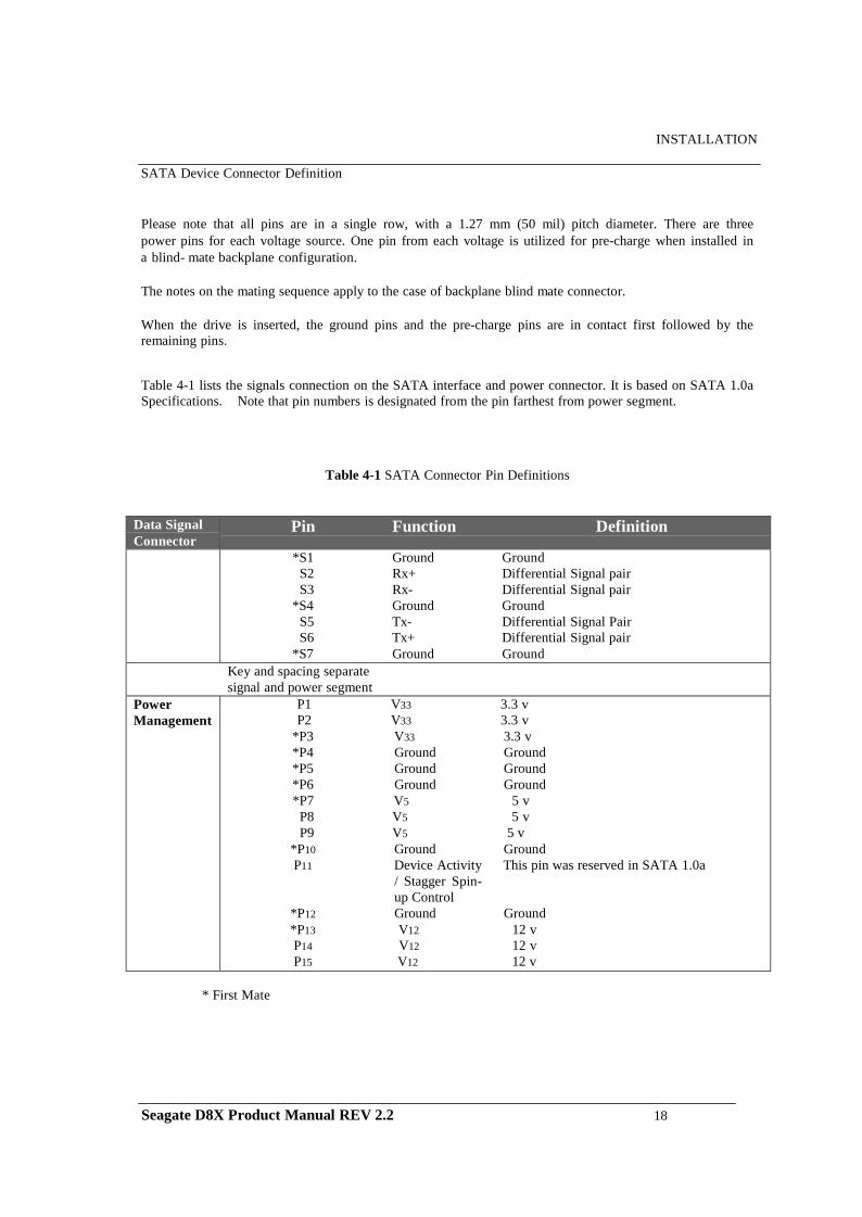
SATA Device Connector Definition
Please note that all pins are in a single row, with a 1.27 mm (50 mil) pitch diameter. There are three power pins for each voltage source. One pin from each voltage is utilized for pre-charge when installed in a blind- mate backplane configuration.
The notes on the mating sequence apply to the case of backplane blind mate connector.
When the drive is inserted, the ground pins and the pre-charge pins are in contact first followed by the remaining pins.
Table 4-1 lists the signals connection on the SATA interface and power connector. It is based on SATA 1.0a Specifications. Note that pin numbers is designated from the pin farthest from power segment.
Table 4-1 SATA Connector Pin Definitions
Data Signal Connector
Pin Function Definition
*S1 Ground Ground S2 Rx+ Differential Signal pair S3 Rx- Differential Signal pair
*S4 Ground Ground S5 Tx- Differential Signal Pair S6 Tx+ Differential Signal pair
*S7 Ground Ground Key and spacing separate signal and power segment
Power Management
P1 V33 3.3 v P2 V33 3.3 v
*P3 V33 3.3 v *P4 Ground Ground *P5 Ground Ground *P6 Ground Ground *P7 V5 5 v
P8 V5 5 v P9 V5 5 v
*P10 Ground Ground P11 Device Activity This pin was reserved in SATA 1.0a
/ Stagger Spin- up Control
*P12 Ground Ground *P13 V12 12 v P14 V12 12 v P15 V12 12 v
* First Mate
Seagate D8X Product Manual REV 2.2 18
INSTALLATION
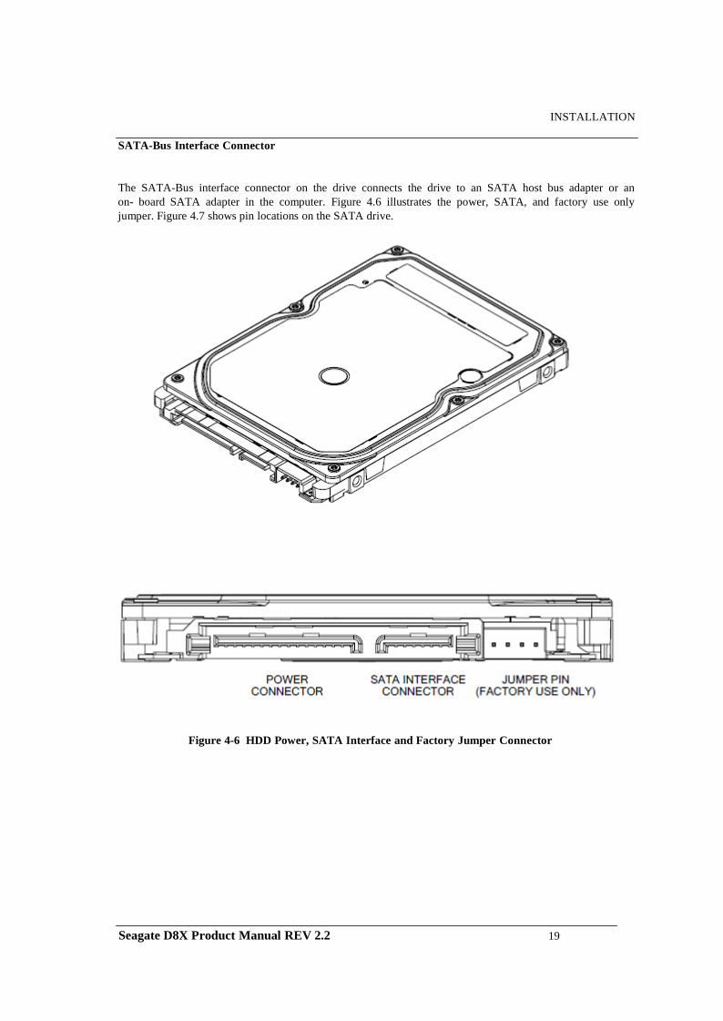
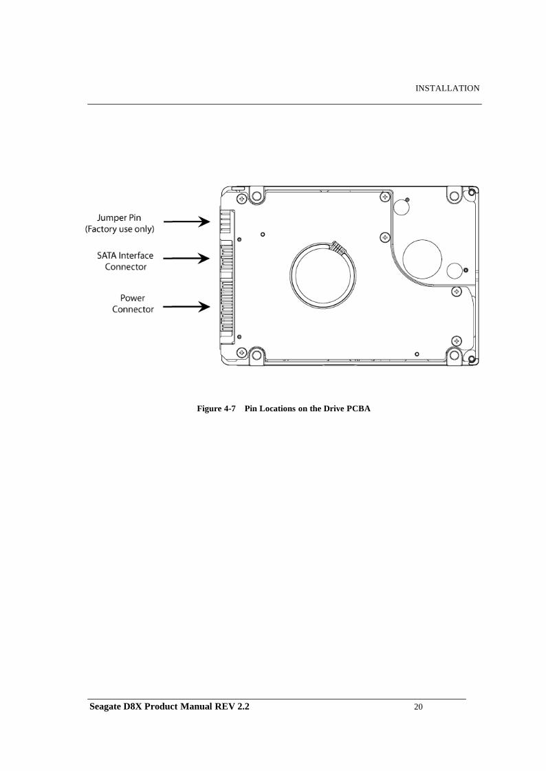
SATA-Bus Interface Connector
The SATA-Bus interface connector on the drive connects the drive to an SATA host bus adapter or an on- board SATA adapter in the computer. Figure 4.6 illustrates the power, SATA, and factory use only jumper. Figure 4.7 shows pin locations on the SATA drive.
Figure 4-6 HDD Power, SATA Interface and Factory Jumper Connector
Seagate D8X Product Manual REV 2.2 19
INSTALLATION
Figure 4-7 Pin Locations on the Drive PCBA
Seagate D8X Product Manual REV 2.2 20
INSTALLATION
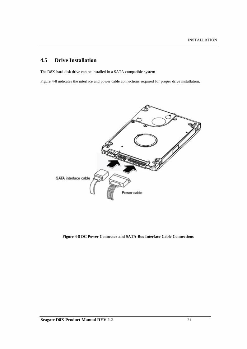
4.5 Drive Installation
The D8X hard disk drive can be installed in a SATA compatible system
Figure 4-8 indicates the interface and power cable connections required for proper drive installation.
Figure 4-8 DC Power Connector and SATA-Bus Interface Cable Connections
Seagate D8X Product Manual REV 2.2 21
CHAPTER 5 DISK DRIVE OPERATION
This chapter describes the operation of the D8X hard disk drive functional subsystems. It is intended as a guide to the operation of the drive, rather than a detailed theory of operation.
5.1 Head / Disk Assembly (HDA)
The D8X hard disk drive consists of a mechanical sub-assembly and a printed circuit board assembly (PCBA), as shown in Figure 5-1. This section describes the mechanism of the drive.
The head / disk assembly (HDA) contains the mechanical sub-assemblies of the drive, which are sealed between the aluminum-alloy base and cover. The HDA consists of the base casting assembly (which includes the DC spindle motor assembly), the disk stack assembly, the head stack assembly, and the rotary voice coil motor assembly (which includes the actuator latch assembly). The HDA is assembled in a clean room. These subassemblies cannot be adjusted or field repaired.
CAUTION: To avoid contamination in the HDA, never remove or adjust its cover and seals. Disassembling the HDA voids your warranty.
The D8X hard disk drive models and capacities are distinguished by the number of heads and disks. The ST320LM001 have one (1) disk and two (2) read/write heads. The ST500LM012 has one (1) disk and two (2) heads. The ST750LM022 have two (2) disks and three / four (3/4) read/write heads. The ST1000LM024 has two (2) disks and four (4) read/write heads.
5.1.1 Base Casting Assembly
A one piece, aluminum-alloy base casting provides a mounting surface for the drive mechanism and PCBA. The base casting also serves as the flange for the DC spindle motor assembly. A gasket provides a seal between the base and cover castings that enclose the drive mechanism.
5.1.2 DC Spindle Motor Assembly
The DC spindle motor assembly consists of the brush-less three-phase motor, spindle bearing (FDB) assembly, disk mounting hub, and a labyrinth seal. The entire spindle motor assembly is completely enclosed in the HDA and integrated to the base casting. The labyrinth seal prevents bearing lubricant from coming out into the HDA. The motor rotates the spindle shaft at 7200 rpm.
Seagate D8X Product Manual REV 2.2 22
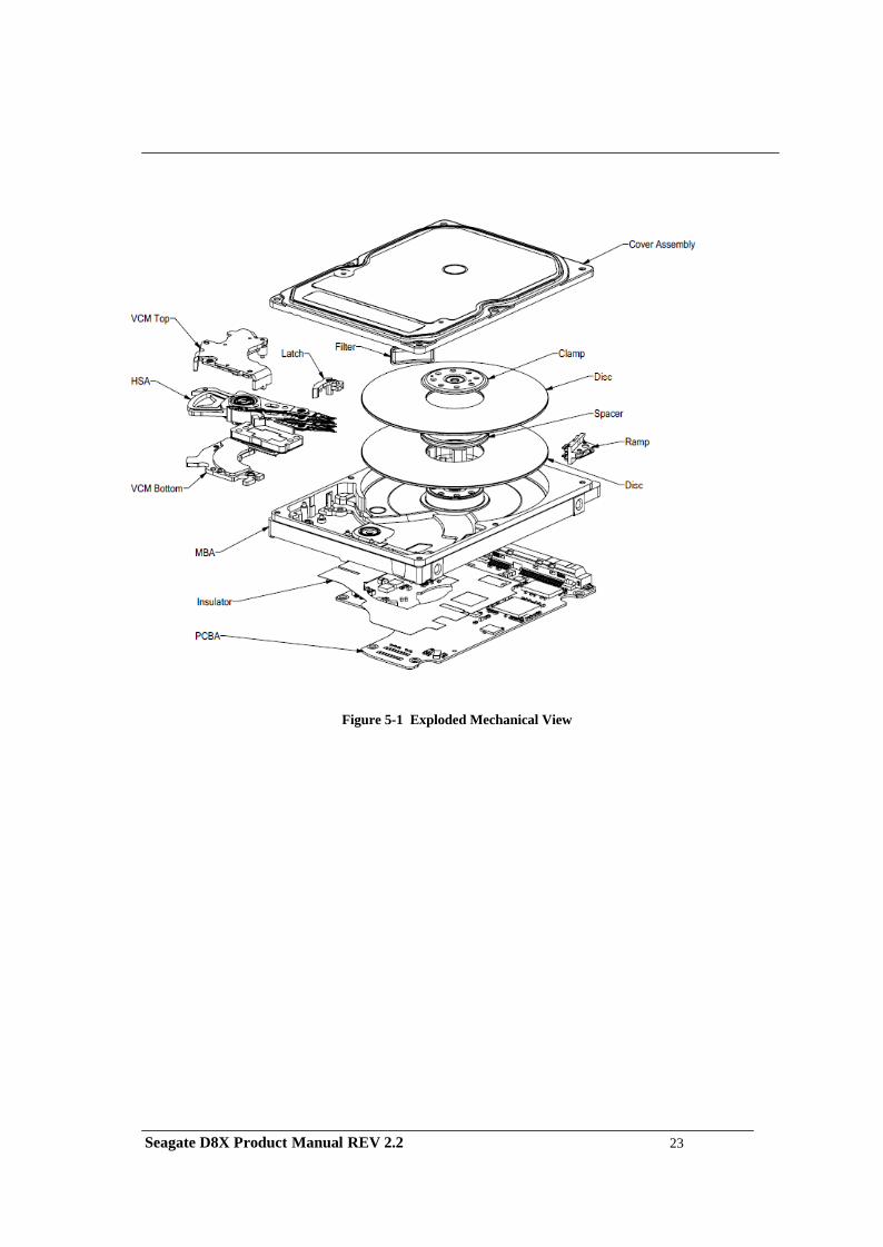
Figure 5-1 Exploded Mechanical View
Seagate D8X Product Manual REV 2.2 23
5.1.3 Disk Stack Assembly
The disk stack assembly in the D8X hard disk drive consists of 1 or 2 disks and disk spacers secured on the hub of the spindle motor assembly by a disk clamp. The glass disks have a sputtered thin-film magnetic coating.
5.1.4 Head Stack Assembly
The head stack assembly consists of an E-block/coil sub-assembly, read/write heads, a flexible circuit, and bearings. The E-block/coil sub-assembly is assembled with an E-block and over-molded coil. Read/write heads are mounted to spring-stainless steel flexures that are then swage mounted onto the E-block arms.
The flexible circuit connects the read/write heads with the PCBA via a connector through the base casting. The flexible circuit contains a read/write Preamplifier IC.
5.1.5 Voice Coil Motor and Actuator Latch Assemblies
The rotary voice coil motor consists of upper and lower permanent magnets and magnetic yokes fixed to the base casting and a rotary over-molded coil on the head stack assembly. Each magnet consists of two alternating poles and is attached to the magnet yoke. Pawl latch and rubber crash stops mounted on a magnetic yoke physically prevent the head(s) from moving beyond the designed inner boundary into the spindle or off the disk surface. Current from the power amplifier induces a magnetic field in the voice coil. Fluctuations in the field around the permanent magnets move the voice coil so that heads can be positioned in the requested cylinder.
5.1.6 Air Filtration System
Heads fly very close to the disk surfaces. Therefore, it is very important that air circulating within the drive be maintained free of particles. Seagate HDAs are assembled in a purified air environment to ensure cleanliness and then sealed with a gasket. To retain this clean air environment, the D8X hard disk drive is equipped with a re-circulating filter, which is located in the path of the airflow close to the rotating disk and is designed to trap any particles that may develop inside HDA.
5.1.7 Load/Unload Mechanism
Portable computer is exposed to heavy handling environment comparing with desk top computer. Load/Unload mechanism provides to protect data loss caused by head hitting to disk due to the abnormal shock and vibration in the transportation and handling. When power is shut down, head will move to parking position on the ramp.
Seagate D8X Product Manual REV 2.2 24
5.2 D r i v e Electronics
The D8X hard disk drive attains its intelligence and performance through the specialized electronic components mounted on the PCBA. The components are mounted on one side of the PCBA.
The Preamplifier IC is the only electrical component that is not on the PCBA. It is mounted on the flexible circuit inside the HDA. Locating the Preamplifier IC as close as possible to the read/write heads via surface mount technology improves the signal to noise ratio.
5.2.1 Digital Signal Process and Interface Controller
The DSP core controller has a dual ARM CPU that incorporates a true 32-bit digital signal processor (DSP), a bus controller unit (BCU), an interrupt controller unit (ICU), a general purpose timer (GPT), and SRAM.
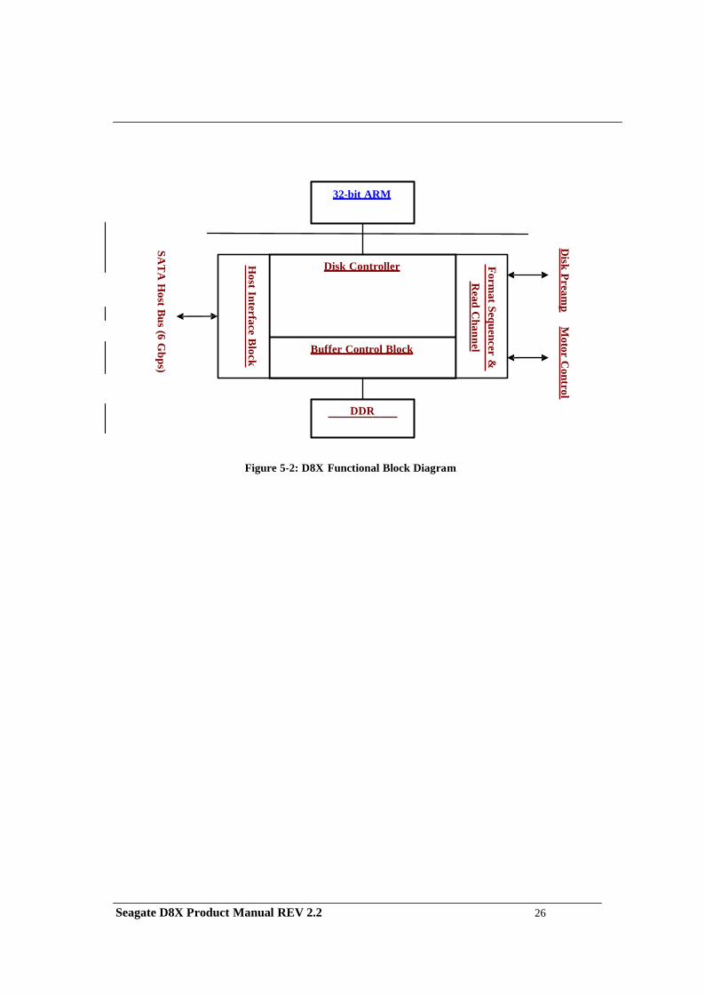
5.2.2 Disk Controller
The AT disk controller works in conjunction with the DSP core to perform the ATA interface control, buffer data flow management, disk format/read/write control, and error correction functions of an embedded disk drive controller. The DSP communicates with the disk controller module by reading from and writing to its various internal registers.
To the DSP core, the registers of the disk controller appear as unique memory or I/O locations that are randomly accessed and operated upon. By reading from and writing to the registers, the DSP core initiates operations and examines the status of the different functional blocks. Once an operation is started, successful completion or an error condition may cause the disk controller to interrupt the DSP core, which then examines the status registers of the disk controller and determines an appropriate course of action. The local DSP core may also poll the device to ascertain successful completion or error conditions.
Figure 5-2 illustrates the relationships between the various blocks within the AT disk controller. These blocks will be referred to throughout this document.
Seagate D8X Product Manual REV 2.2 25
Disk Pream
p M
otor Control
Format Sequencer &
R
ead Channel
Host Interface B
lock
SAT
A H
ost Bus ( 6 Gbps)
32-bit ARM
Disk Controller
Buffer Control Block
DDR
Figure 5-2: D8X Functional Block Diagram
Seagate D8X Product Manual REV 2.2 26
5.2.2.1 The Host Interface Control Block
The SATA Disk Controller provides direct interface to an SATA bus. It is compatible with ATA 7 Specs. It provides a means for the host to access the Task File registers used to control the transfer of data between host memory and the disk drive.
The SATA Host Interface Control block can be programmed to execute various host read/write commands either completely automatically without any DSP intervention, semi-automatically with minimal DSP intervention, or manually with the aid of the DSP. The Disk Controller has significant advances in ATA automation. The highlights of ATA automation includes:
Automatic data transfer management for multi-sector Read/Write commands without DSP intervention. Automatic execution of read commands (Auto-Read command execution) for cached data in the buffer by
matching the first sector. Automatic Task File registers updates during automatic multi-sector transfers. Automatic NCQ queue tag validation
D8X supports PIO, DMA, and FPDMA data transfers. The supported DMA type transfers include multi-word (MWDMA) and synchronous Ultra DMA (UDMA) transfers. The bus emulates automatically switched between 16- and 8-bit mode while performing Read Long and Write Long commands at the time of ECC byte transfers.
Additional functionality is provided in the Host Interface Block by the following features:
Programmable transfer length for automatic ECC byte transfer on the AT bus. Support of both LBA and CHS Task File registers formats. Automatic detection of both the Software Reset and COMRESET. Support for PIO modes 0 through 4. Support for multiword DMA modes 0 through 2. Support for multiword DMA modes 0 through 2. Support for synchronous DMA (UDMA) transfer mode 0 through 7. (Mode 7 is referring to 150 MB/S) Support for First Party DMA (FDMA) for NCQ commands.
5.2.2.2 The Buffer Control Block
The Buffer Control block manages the flow of data into and out of the buffer. Significant automation allows buffer activity to take place automatically during read/write operations between the host and the disk. This automation works together with automation within the Host Interface Control and Disk Control blocks to provide more bandwidth for the local microprocessor to perform non-data flow functions. The buffer control circuitry keeps track of buffer full and empty conditions and automatically works with the Disk Control block to stop transfers to or from the disk when necessary. In addition, transfers to or from the host are automatically stopped or started based on buffer full or empty status. A prioritized five ports architecture is implemented. All ports, except the refresh port, utilize 22-bit buffer address pointers. The data path to the buffer RAM can be configured as 16-bit path in ATA mode.
Seagate D8X Product Manual REV 2.2 27
Additional functionality is provided in the Buffer Control block through the following features: Increased automation to support minimal latency read operations with minimal latency. Capability to support the execution of multiple consecutive Auto-Write commands without
loss of data due to overwriting of data. Auto write pointer. A disk sector counter that can monitor the transfers between the disk and buffer. Read/Write cache support.
5.2.2.3 The Disk Control Block
The D8X Disk Control block manages the flow of data between the disk and the buffer. It is capable of performing completely automated track read and write operations at a maximum data rate of 800 Mb/s in byte wide NRZ mode. Many flexible features and elements of automation have been incorporated to complement the automation contributed by the Host and Buffer blocks. The Disk Control block consists of the programmable sequencer (Disk Sequencer), CDR/data split logic, disk FIFO, fault tolerant sync detect logic, and other support logic. The programmable sequencer contains a 31-by-4 byte programmable SRAM and associated control logic, which is programmed by the user to automatically control all single track format, read, and write operations. From within the sequencer micro program, the Disk Control block can automatically deal with such real time functions as defect skipping, servo burst data splitting, branching on critical buffer status and data compare operations. Once the Disk Sequencer is started, it executes each word in logical order. At the completion of the current instruction word, it either continues to the next instruction, continues to execute some other instruction based upon an internal or external condition having been met, or it stops. During instruction execution or while stopped, registers can be accessed by the DSP to obtain status information reflecting the Disk Sequencer operations taking place.
5.2.2.4 The Disk LDPC Control Block
The Disk Control Block supports a programmable LDPC code. Error detection and correction is handled in the Disk Control block. Automatic on-the-fly hardware correction will take place. Correction is guaranteed to complete before the parity bits of the sector following the sector where the error occurred utilizing standard ATA size sectors.
5.2.2.5 Frequency Synthesizer
The frequency synthesizer is a clock frequency generation circuit used to generate a DSP clock, AT disk controller and servo clock from the External Reference clock input.
Seagate D8X Product Manual REV 2.2 28
5.2.2.6 Power Management
Power management features are incorporated into each block of the D8X. This allows the designer to tailor the amount of power management to the specified design. Other power management features include: Independent power management control for each block. DSP block powered down and up when needed. Disk Sequencer and associated disk logic powered up when the Disk Sequencer is started. Weak pull-up structure on input pins to prevent undesirable power consumption due to
floating CMOS inputs.
5.2.3 Read/Write IC
The Read/Write IC, shown in Figure 5-3 provides read/write-processing functions for the drive. The Read/Write IC receives the Read GATE and Write GATE signals, write data, and servo AGC and gates from the Interface Controller. The Read/Write IC sends decoded read data and the read reference clock. It receives write data from the Interface Controller. The 88C9410 which is embedded in 88i9422 is a sampled-data digital PRML channel designed to work with a disk controller and a read/write preamplifier to provide the signal processing elements required to build a state of the art high density, high speed disk drive. The 88C9410 implements a noise predictive, PRML Viterbi read channel (supporting) zone-bit recording, The read/write channel functions include a time base generator, AGC circuitry, asymmetry correction circuitry (ASC), analog anti-aliasing low-pass filter, analog to digital converter (ADC), digital FIR filter, timing recovery circuits, Viterbi detector, sync mark detection, Iterative code ENDEC, serializer and de-serializer, and write pre-compensation circuits. Servo functions include servo data detection and PES demodulation. Additionally the 88C9410 contains specialized circuitry to perform various parametric measurements on the processed read signal. This allows for implementation of self-tuning and optimization capability in every drive built using the 88C9410. A 12-bit NRZ interface is provided to support high speed data transfers and from the controller. Programming of the 88C9410 is performed through a serial interface. The serial interface is also used to read various channel parameters that are computed on the fly.
5.2.3.1 Time Base Generator
The time base generator provides the write frequency and serves as a reference clock to the synchronizer during non-read mode.
5.2.3.2 Automatic Gain Control
The AGC accepts a differential signal from the pre-amp, and provide constant output amplitude to the analog filter. It’s capable of accepting signal ranges from 50 mV to 400mVppd.
5.2.3.3 Asymmetry Correction Circuitry (ASC)
The ASC circuit is designed to correct for amplitude asymmetry introduced by MR heads. The compensation range of this circuit is +/-30%. This circuit allows optimal bias current to be used independent of the asymmetry effect.
Seagate D8X Product Manual REV 2.2 29
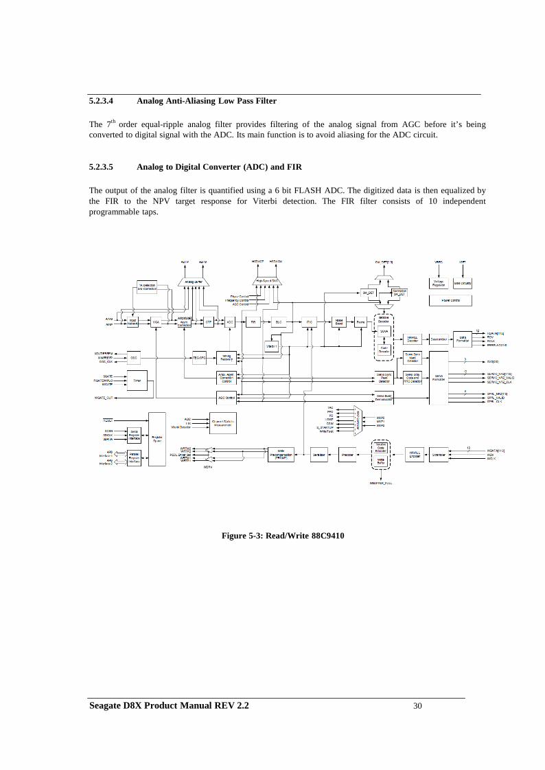
5.2.3.4 Analog Anti-Aliasing Low Pass Filter
The 7th order equal-ripple analog filter provides filtering of the analog signal from AGC before it’s being converted to digital signal with the ADC. Its main function is to avoid aliasing for the ADC circuit.
5.2.3.5 Analog to Digital Converter (ADC) and FIR
The output of the analog filter is quantified using a 6 bit FLASH ADC. The digitized data is then equalized by the FIR to the NPV target response for Viterbi detection. The FIR filter consists of 10 independent programmable taps.
Figure 5-3: Read/Write 88C9410
Seagate D8X Product Manual REV 2.2 30
5.3 Servo System
The Servo System controls the position of the read/write heads and holds them on track during read/write operations. The Servo System also compensates for MR write/read offsets and thermal offsets between heads on different surfaces and for vibration and shock applied to the drive. The D8X hard disk drive is an Embedded Sector Servo System. Positioning information is radially located in evenly spaced servo sectors on each track. Radial position information can be provided from these sectors for each data head. Because the drive incorporates multiple data zones and each zone has a different bit density, split data fields are necessary for optimal use of the non-servo area of the disk. The servo area remains phase-coherent across the surface of the disk, even though the disk has various data zones. The main advantage of the Embedded Sector Servo System is that it eliminates the problems of static and dynamic offsets between heads on different surfaces. The D8X hard disk drive Servo System is classified as a digital servo system because track-following and seek control, bias cancellation, and other typical tasks are done in a Digital Signal Processor (DSP). The Servo system has three modes of operation: track-following mode, settle mode, and velocity control mode.
1. Track-following mode is used when heads are “on-track.” This is a position loop with an
integrator in the compensation.
2. Settle mode is used for all accesses; head switches, short-track seeks and long-track seeks. Settle mode is a position loop with velocity damping. Settle mode does not use feed forward.
3. Velocity control mode is used for acceleration and deceleration of the actuator for seeking of two or more tracks. A seek operation of this length is accomplished with a velocity control loop. The drive’s ROM stores the velocity profile in a look-up table.
5.4 Read and Write Operations
The following two sections describe the read and write channels.
5.4.1 The Read Channel
The drive has one read/write head for each of the data surfaces. The signal path for the Read Channel starts at the read/write heads. When the magnetic flux transitions recorded on a disk pass under the head, they generate low-amplitude, differential output voltages. The read/write head transfers these signals to the flexible circuit’s amplifier, which amplifies the signal. The flexible circuit transmits the pre-amplified signal from the HDA to the PCBA. The EPRML channel on the PCBA shapes, filters, detects, synchronizes, and decodes the data from the disk. The Read/Write IC then sends the resynchronized data output to the 88i9422 (Rev3.1) DSP & Interface/Disk Controller. The 88i9422 Disk Controller manages the flow of data between the Data Synchronizer on the Read/Write IC and its AT Interface Controller. It also controls data access for the external RAM buffer. The ENDEC of 88C9410 decodes the LDPC with post-processor format to produce a serial bit stream. This NRZ (Non Return to Zero) serial data is converted to 12-bits. The Sequencer module identifies the data as belonging to the target sector. After a full sector is read, the 88i9422 checks to see if the firmware needs to apply an ECC algorithm to the data. The Buffer Control section of the 88i9422 stores the data in the cache and transmits the data to the AT bus.
Seagate D8X Product Manual REV 2.2 31
5.4.2 The Write Channel
The signal path for the Write Channel follows the reverse order of that for the Read Channel. The host transmits data via the AT bus to the 88i9422 Interface Controller. The Buffer Controller section of the 88i9422 stores the data in the cache. Because the data is transmitted to the drive at a rate that exceeds the rate at which the drive can write data to the disk, data is stored temporarily in the cache. Thus, the host can present data to the drive at a rate independent of the rate at which the drive can write data to the disk. Upon correct identification of the target address, the data is shifted to the Sequencer, which generates and appends an error correcting code. The Sequencer then converts the bytes of data to a serial bit stream. The AT controller also generates a preamble field, inserts an address mark, and transmits the data to the ENDEC in the R/W IC where the data is encoded into the LDPC format and pre-compensates for non-linear transition shift. The amount of write current is set by the 88i9422 DSP and Interface/Disk Controller through the serial interface to the preamplifier. The 88i9422 switches the Preamplifier and Write Driver IC to write mode and selects a head. Once the Preamplifier and Write Driver IC receive a write gate signal, it transmits current reversals to the head, which writes magnetic transitions on the disk.
5.5 Firmware Features
This section describes the following firmware features:
Read Caching Write Caching Track Skewing Defect Management Automatic Defect Allocation ECC Correction SMART (Self-monitoring and reporting technology) ATA security mode features ATA host protected area ATA streaming features ATA power up in stand by feature set ATA advanced power management (APM) feature set ATA device configuration overlay (DCO) feature set
5.5.1 Read Caching The D8X hard disk drive uses Read Cache to enhance drive performance and significantly improve system throughput. Use the SET FEATURES command to enable or disable Read Caching. Read caching anticipates host-system requests for data and stores that data for faster future access. When the host requests a certain segment of data, the cache feature utilizes a prefetch strategy to get the data in advance and automatically read and store the following data from the disk into fast RAM. If the host requests this data, the RAM is accessed rather than the disk.
There is a high probability that subsequent data requested will be in the cache, because more than 50 percent of all disk requests are sequential. It takes microseconds rather than milliseconds to retrieve this cached data. Thus Read
Seagate D8X Product Manual REV 2.2 32
Caching can provide substantial time savings during at least half of all disk requests. For example, Read Caching could save most of the disk transaction time by eliminating the seek and rotational latency delays that prominently dominate the typical disk transaction. Read Caching operates by continuing to fill its cache memory with adjacent data after transferring data requested by the host. Unlike a non-caching controller, the 88i6526 Interface Controller continues a read operation after the requested data has been transferred to the host system. This read operation terminates after a programmed amount of subsequent data has been read into the cache memory. The cache memory consists of a sync DRAM buffer allocated to hold the data. It can be directly accessed by the host by means of read and write commands. The unit of data stored is the logical block, or a multiple of the 512-byte sector. Therefore, all accesses to cache memory must be in multiples of the sector size. The following commands empty the cache:
IDENTIFY DRIVE (ECh) FORMAT TRACK (50h) EXECUTE DRIVE DIAGNOSTIC (90h) READ LONG (23h) WRITE VERIFY (3Ch) INITIALIZE DEVICE PARAMETER (91h) SLEEP (99h, E6h) STANDBY IMMEDIATELY (94h, E0h) READ BUFFER (E4h) WRITE BUFFER (E8h) WRITE SAME (E9h)
5.5.2 Write Caching
Write caching improves both single and multi-sector write performance by reducing delays introduced by rotational latency. When the drive writes a pattern of multiple sequential data, it stores the data to a cache buffer and immediately sends a COMMAND COMPLETE message to the host before it writes the data to the disk.
The data is then written collectively to the drive thereby minimizing the disk seeking operation. Data is held in cache no longer than the maximum seek time plus rotational latency. Host retries must be enabled for Write Caching to be active.
If the data request is random, the data of the previous command is written to the disk before COMMAND COMPLETE is posted for the current command. Read commands work similarly. The previous write is allowed to finish before the read operation starts.
If a defective sector is found during a write, the sector is automatically relocated before the write occurs. This ensures that cached data that already has been reported as written successfully gets written, even if an error should occur. If the sector is not automatically relocated, the drive drops out of write caching and reports the error as an ID Not Found. If the write command is still active on the AT interface, the error is reported during that command. Otherwise, it is reported on the next command.
Seagate D8X Product Manual REV 2.2 33
5.5.3 Defect Management
The D8X hard disk drive media is scanned for defects. After defect scanning, the defective sectors are saved in the defect list. A defect encountered in the manufacturing process is slipped to the next physical sector location. All logical sector numbers are pushed down to maintain a sequential order of data. The read/write operation can “slip” over the defective sectors so that the only performance impact is idle time.
5.5.4 Automatic Defect Allocation
The automatic defect allocation feature automatically maps out defective sectors encountered during read sector or write sector operations. These types of defective sectors are typically caused by grown defects. During write operations, if write errors are encountered, all sectors within the target servo frame are mapped out. Original data is transferred and written into designated reserved sector areas determined by the HDD firmware.
5.5.5 SMART
The intent of Self-monitoring, Analysis and Reporting Technology (SMART) is to protect user data and to minimize the likelihood of unscheduled system downtime that may be caused by unpredictable degradation and/or device fault. By monitoring and storing critical performance and calibration parameters, SMART devices attempt to predict the likelihood of near-term degradation or fault condition. Providing the host system knowledge of a negative reliability condition allows the host system to warn the user of the impending risk of a data loss and advise the user of appropriate action.
5.5.6 APM
The Automatic Power Management (APM) feature set is an optional feature set that allows the host to select a power management level. The power management level is specified using a scale from the lowest power consumption setting to the maximum performance level. Device performance may increase with increasing power management levels. Device power consumption may increase with increasing power management levels. This feature is enabled by the Set Features command.
Seagate D8X Product Manual REV 2.2 34
CHAPTER 6 SATA III INTERFACE
6.1 Introduction
The D8X disk drive is equipped with an industry standard SATA Interface fully supports and enhances PC mass storage requirements. The SATA interface conforms to the Serial ATA standards in Cabling, in Physical Signals, and in Logical Programming schemes. The D8X disk drive joins the industry premiere VLSI circuitry with ingenious programming skill that does not compromise performance or reliability. Seagate integrates and delivers the cutting edge in technology. Seagate D8X SATA class disk drives are designed to relieve and to enhance the I/O request processing function of system drivers.
6.1.1 SATA Terminology
The following contains some commonly proposed terminology used in SATA technology.
BACKCHANNEL-A term used to describe or refer to the transmit same-side of SATA interface, when the scope of the paragraph is addressing the receive interface. For example, when discussing the receive SATA interface on the device side, the term “backchannel” would be used to describe the transmit interface on the device side.
CHARACTER ALIGNMENT-Character alignment is a receiver action that resets the character boundary to that of the comma sequence found in the K28.5 control character of the ALIGN primitive, and establishes Dword synchronization of the incoming serial data stream.
CHARACTER SLIPPING-Character slipping is the receiver action that realigns the receiver’s clock to the received bit stream by adding or removing bit times within the characters of the ALIGN primitive.
CODE VIOLATION- A code violation is an error that occurs in the reception process as a result of (1) a running disparity violation or (2) an encoded character that does not translate to a valid data or control character or (3) an encoded character that translates to a control character other than K28.5 or K28.3 in byte 0 of a Dword or (4) an encoded character that translates to any control character (valid or invalid) in bytes 1-3 of a Dword.
COMMA CHARACTER- A comma character is a control character, that when encoded, contains the comma sequence. In Serial ATA the only comma character used is K28.5, and only the ALIGN primitive contains the comma character. The comma sequence is the first seven bits of the encoded character.
COMMA SEQUENCE- The comma sequence is a seven-bit sequence of 0011111 or 1100000 in an encoded stream. The comma sequence is unique in that it appears only in a single encoded character, and furthermore, cannot appear in any subset of bits in adjacent encoded characters. This unique property allows the comma sequence to be used for determining alignment of the received data stream.
COMRESET / COMINIT- Host: Signal from the out of band detector that indicates the COMINIT out of band signal is being detected.
CONTROL CHARACTER- A control character is a combination of a byte value with the control variable equal to K. Seagate D8X Product Manual REV 2.2 35
CONTROL VARIABLE-The control variable, Z, is a flag that determines the code set to be used to interpret a data byte. The control variable has the value D (for data characters) or K (for control characters).
CRC-In Serial ATA a 32-bit CRC is calculated over the contents of a FIS. The Serial ATA CRC is the Dword in a frame that immediately precedes the EOF primitive.
DATA CHARACTER-A data character is a combination of a byte value with the control variable equal to D.
DWORD-A Dword is thirty-two (32) bits of data. A Dword may be represented as 32 bits, as two adjacent words, or as four adjacent bytes. When shown as bits the least significant bit is bit 0 and most significant bit is bit 31. The most significant bit is shown on the left. When shown as words the least significant word (lower) is word 0 and the most significant (upper) word is word 1. When shown as bytes the least significant byte is byte 0 and the most significant byte is byte 3.
DWORD SYNCHRINIZATION-The state in which a receiver has recognized the comma sequence and is producing an aligned data stream of Dwords (four contiguous bytes) from the zero-reference of the comma character.
ENCODED CHARACTER-An encoded character is the output of the 8b/10b encoder – the result of encoding a character. An encoded character consists of 10 bits, where bit 0 is the most significant bit and bit 9 is the least significant. The bits in an encoded character are symbolically referred to as “abcdeifghj” where “a” corresponds to bit 0 and “j” corresponds to bit 9.
ELASTICITY BUFFER-The elasticity buffer is a portion of the receiver where character slipping and/or character alignment is performed.
FIRST PARTY DMA ACCESS -First-party DMA access is a method by which a device accesses host memory.
FIRST PARTY DMA MODE (FPDMA) - A device which is operating in First-party DMA mode uses First- party DMA as a primary communications method between the host and the device. A software driver uses legacy mode commands to place the device into First-party DMA mode of operation. The legacy-mode command places the device into the First-party DMA mode of operation and the command protocol used between a device and host when in First-party DMA mode are not specified by this specification.
FIRST DATA PHASE- The FPDMA Data Phase is the period from the reception of a DMA Setup FIS until either the exhaustion of the associated data transfer count or the assertion of the ERR bit in the shadow Status register.
FIS-Stands for Frame Information Structure.
FRAME UNFIORMATION STRUCTURE-The user payload of a frame, does not include the SOF, CRC, and EOF delimiters.
Frame-A frame is an indivisible unit of information exchanged between a host and device. A frame consists of a SOF primitive, a Frame Information Structure, a CRC calculated over the contents of the FIS, and an EOF primitive-
LEGACY MODE-Legacy m o d e is the mode of operation which provides sof tware-transparent communication of commands and status between a host and device using the ATA Command Block and Control Block registers.
LEGAL CHARACTER-Legal character is one for which there exists a valid decoding, either into the data character or control character fields. Due to running disparity constraints not all 10-bit combinations result in a legal character. Additional usage restrictions in Serial ATA result in a further reduction in the SATA defined control character space.
Seagate D8X Product Manual REV 2.2 36
OOB SIGNAL DETECTOR-This block decodes Out of Band signal from the high speed input signal path. PRIMITIVE-A primitive is a single Dword of information that consists of a control character in byte 0 followed by three additional data characters in bytes 1-3.
SHADOW REGISTER BLOCK REGISTERS-Shadow Register Block registers are interface registers used for delivering commands to the device or posting status from the device.
SQUELCH-This block establishes a limit so that detection of a common mode signal can be properly accomplished.
WORD-A word is sixteen (16) bits of data. A word may be represented as 16 bits or as two adjacent bytes. When shown as bits the least significant bit is bit 0 and most significant bit is bit 15. The most significant bit is shown on the left. When shown as bytes the least significant byte (lower) byte is byte 0 and the most significant byte (upper) byte is byte 1.
6.2 Physical Interface
For information please consult the document entitled “Serial ATA: High Speed Serialized AT Attachment Revision 3.2” released on August, 2013 available from the Internet http://www.serialata.org/ .
6.3 Signal Summary
For details, please consult the document entitled “Serial ATA: High Speed Serialized AT Attachment Revision 3.2” released on A u g u s t , 2013 available from Internet http://www.serialata.org/ .
6.3.1 Signal Descriptions
For data packets and additional information please consult the document entitled “Serial ATA: High Speed Serialized AT Attachment Revision 3.2” released on August 2013 available from http://www.serialata.org/ .
A device can operate in either of two addressing modes, CHS or LBA, on a command-by-command basis. The CHS mode is supported for legacy command access only. The task file registers contains the Cylinder, Head, and Sector information of a requested location. Because the disk drive has its own mapping, the CHS mode is translated into disk drive physical address by the HDD firmware. There is no direct relationship of the CHS that can be accessed from the host.
This CHS term defines the addressing mode of the device as being by physical sector address. The physical sector address is made up of three fields: the sector number, the head number and the cylinder number. Sectors are numbered from 1 to a device specific maximum value, which cannot exceed 255. Heads are numbered from 0 to a device specific maximum value, which cannot exceed 15. Cylinders are numbered from 0 to a device specific maximum value, which cannot exceed 65,535. Typically, sequential access to the media is accomplished by treating the sector number as the least significant portion, the head number as the mid portion, and the cylinder number as the most significant portion of the CHS address.
Seagate D8X Product Manual REV 2.2 37
In LBA mode the sectors on the device are assumed to be linearly mapped with an initial definition of: LBA 0 = (Cylinder 0, head 0, and sector 1). Irrespective of translate mode geometry set by the host, the LBA address of a given sector does not change:
6.3.2 I/O Register - Address
The communication to or from drive is through the SATA interface. To the host system the SATA drive emulates a parallel ATA drive. As such, the following registers are not accessed directly host to drive. The registers are set through the Serial Interface.
The Control Block registers are used for drive control and to post-alternate status. I/O port function and its selection address are tabulated.
I/O registers
Command Block registers When read When written
Data Data Error Features Current
Features Previous Sector Count Current Sector Count Previous
Sector Count Current Sector Count Previous
LBA Low Current LBA Low Previous
LBA Low Current LBA Low Previous
LBA Mid Current LBA Mid Previous
LBA Mid Current LBA Mid Previous
LBA High Current LBA High Previous
LBA High Current LBA High Previous
Device Device Status Command
Control Block registers Alternate Status Device Control
6.3.3 Control Block Register Descriptions
6.3.3.1 Alternate Status Register (ex. 3F6h)
This register contains the same information as the Status register in the Command Block register. The only difference is that reading this register does not imply interrupt acknowledgment nor does it clear a pending interrupt.
7 6 5 4 3 2 1 0
BSY
DRDY
#
#
DRQ
Obsolete
Obsolete
ERR
NOTE: See 6.3.4.10 for definitions of the bits in this register.
Seagate D8X Product Manual REV 2.2 38
6.3.3.2 Device Control Register (ex. 3F6h)
The bits in this register are as follows:
7 6 5 4 3 2 1 0
HOB
R
R
R
R
SRST
nIEN
0
• HOB is the High Order Byte used for host to access the Extended Registers in the 48-bit LBA mode • SRST is the host software reset bit. The drive is held reset when this bit is set. If two disk drives are
daisy chained on the interface, this bit resets both simultaneously. • nIEN is the enable bit for the drive interrupt to the host. When nIEN=0, and the drive is selected,
INTRQ is enabled through a tri-state buffer. When nIEN=1, or the drive is not selected, the INTRQ signal is in a high impedance state.
• R is for reserved
6.3.4 Command Block Register Descriptions
6.3.4.1 Data Register (Ex. 1F0h)
This 16-bit register is used to transfer data blocks between the device data buffer and the host. It is also the register through which sector information is transferred on a Format Track command. Data transfers may be either PIO or DMA.
6.3.4.2 Features Register and Feature Extended Register (Ex. 1F1h)
This register is command specific and used to enable and disable features of the interface (e.g., by the Set Features command to enable and disable caching). The Feature Extended Register contains the upper byte of the Feature Register.
6.3.4.3 Sector Number Register and Sector Number Extended Register (Ex. 1F3h)
In CHS mode this register contains the starting sector number for any disk data access for the subsequent command. The sector number is from 1 to the maximum number of sectors per track. In LBA mode this register contains bits 0-7 of the LBA. The Sector Number Extended Register is for bits 25-31 of the 48-bit LBA. See the command descriptions for the contents of the register at command completion (whether successful or unsuccessful).
6.3.4.4 Error Register (Ex. 1F1h)
This register contains status from the last command executed by the drive or a Diagnostic Code. At the completion of any command except Execute Drive Diagnostic, the contents of this register are valid when ERR=1 in the Status register.
Following a power-on, a reset, or completion of an Execute Drive Diagnostic command, this register contains a Diagnostic Code.
7 6 5 4 3 2 1 0
#
#
#
#
#
ABRT
#
#
Seagate D8X Product Manual REV 2.2 39
• ABRT (Aborted Command) indicates the requested command has been aborted due to a
drive status error (Not Ready, Write Fault, etc.) or because the command code is invalid. • # Indicates the content of this bit is command dependent.
NOTE: Unused bits are cleared to zero.
6.3.4.5 Sector Count Register and Sector Count Extended Register (Ex. 1F2h)
This register contains the number of sectors of data requested to be transferred on a read or write operation between the host and the drive. In 28-bit addressing, if the value in this register is zero, a count of 256 sectors is specified. In 48-bit addressing, the Sector Count Register is the low order byte of the 16-bit sector count value and the Sector Count Extended Register is the high order byte of the 16-bit sector count value.
If this register is zero at command completion, the command was successful. If not successfully completed, the register contains the number of sectors, which need to be transferred in order to complete the request.
The contents of this register may be defined otherwise on some commands (e.g., Initialize Drive Parameters command, Format Track command).
6.3.4.6 Cylinder High Register and Cylinder High Extended Register (Ex. 1F5h)
In CHS mode the Cylinder High Register contains the high order bits of the starting cylinder address for any disk access. In LBA mode the Cylinder High Register contains bits 16-23 of the LBA. The Cylinder High Extended Register contains bits 40-47 of the 48-bit LBA.
At the end of the command, this register is updated to reflect the current disk address. The most significant bits of the cylinder address are loaded into the Cylinder High register.
6.3.4.7 Cylinder Low Register and Cylinder Low Extended Register (Ex. 1F4h)
In CHS mode the Cylinder Low Register contains the low order 8 bits of the starting cylinder address for any disk access. In LBA mode the Cylinder Low Register contains bits 8-15 of the LBA. The Cylinder Low Extended Register contains bits 32-39 of the 48-bit LBA. At the end of the command, this register is updated to reflect the current disk address.
6.3.4.8 Command Register (Ex. 1F7h)
This register contains the command code being sent to the drive. Command execution begins immediately after this register is written. The executable commands, the command codes, and the necessary parameters for each command are listed.
6.3.4.9 Device Register (Ex. 1F6h)
This register contains the drive and head numbers. When executing an Initialize Drive Parameters command, the content of this register defines the number of heads minus 1.
7 6 5 4 3 2 1 0
Obsolete
LBA
Obsolete
DEV
#
#
#
#
Seagate D8X Product Manual REV 2.2 40
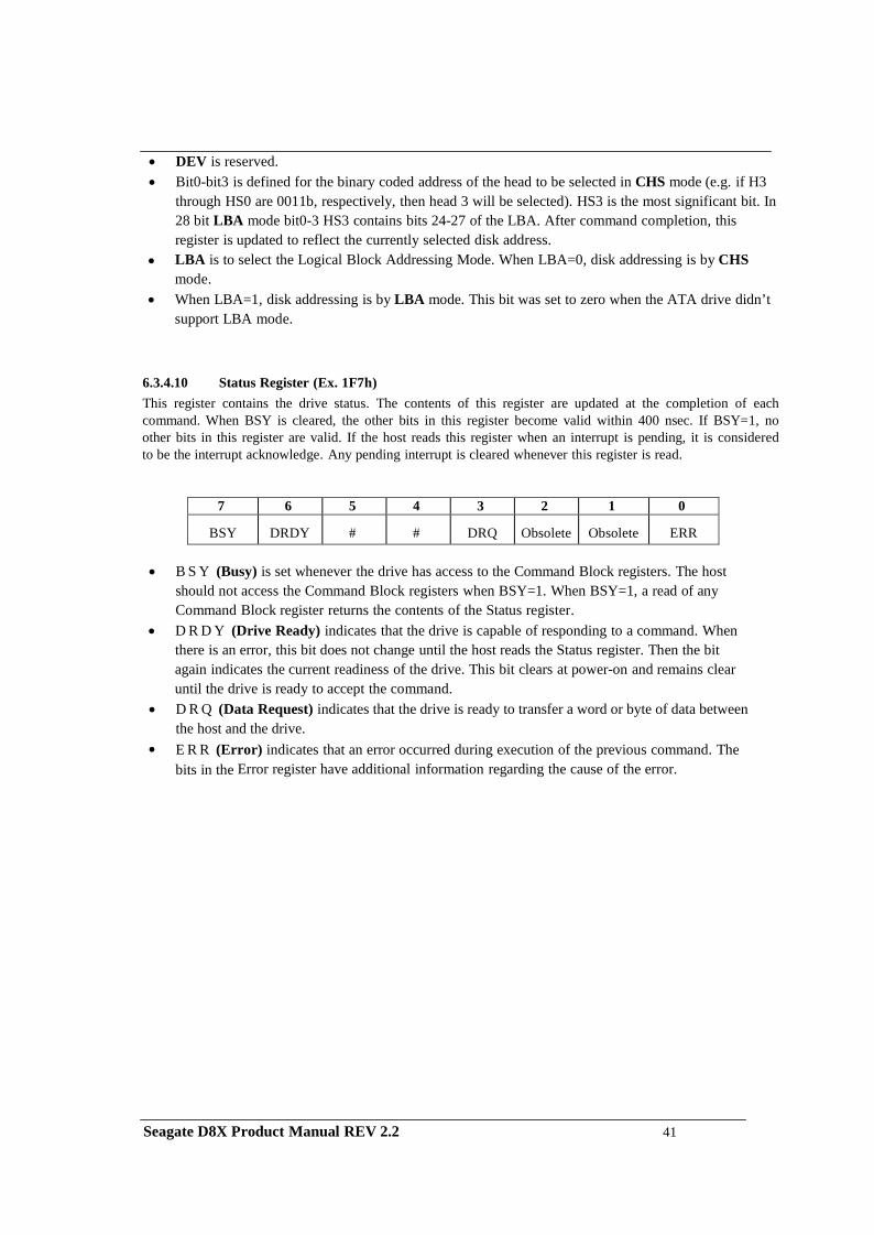
• DEV is reserved. • Bit0-bit3 is defined for the binary coded address of the head to be selected in CHS mode (e.g. if H3
through HS0 are 0011b, respectively, then head 3 will be selected). HS3 is the most significant bit. In 28 bit LBA mode bit0-3 HS3 contains bits 24-27 of the LBA. After command completion, this register is updated to reflect the currently selected disk address.
• LBA is to select the Logical Block Addressing Mode. When LBA=0, disk addressing is by CHS mode.
• When LBA=1, disk addressing is by LBA mode. This bit was set to zero when the ATA drive didn’t support LBA mode.
6.3.4.10 Status Register (Ex. 1F7h) This register contains the drive status. The contents of this register are updated at the completion of each command. When BSY is cleared, the other bits in this register become valid within 400 nsec. If BSY=1, no other bits in this register are valid. If the host reads this register when an interrupt is pending, it is considered to be the interrupt acknowledge. Any pending interrupt is cleared whenever this register is read.
7 6 5 4 3 2 1 0
BSY
DRDY
#
#
DRQ Obsolete
Obsolete
ERR
• B S Y (Busy) is set whenever the drive has access to the Command Block registers. The host
should not access the Command Block registers when BSY=1. When BSY=1, a read of any Command Block register returns the contents of the Status register.
• D R D Y (Drive Ready) indicates that the drive is capable of responding to a command. When there is an error, this bit does not change until the host reads the Status register. Then the bit again indicates the current readiness of the drive. This bit clears at power-on and remains clear until the drive is ready to accept the command.
• D R Q (Data Request) indicates that the drive is ready to transfer a word or byte of data between the host and the drive.
• E R R (Error) indicates that an error occurred during execution of the previous command. The bits in the Error register have additional information regarding the cause of the error.
Seagate D8X Product Manual REV 2.2 41
CHAPTER 7 SATA III FEATURE SET
This section describes the SATA III feature set supported in the Seagate D8X drive.
7.1 Device Activity Signal
D8X implemented the Device Activity Signal on the SATA power connector pin-11. The implementation is based on the SATA III specification. This activity signal is used for indicating the drive activities, including the queued and non-queued commands. For the host can use this signal to indicate the command activity.
7.2 Staggered Spin-up Disable Control
D8X implemented the staggered spin-up disable control by using the SATA power connector pin-11. This pin is multiplexed with the Device Activity Signal support. On power up this pin is used for the spin-up control. After the device is connected with the host, this pin is used for the Device Activity.
Before the device spins up its media, devices that support staggered spin-up disable control shall detect whether pin 11 is asserted low by the host. If pin 11 is asserted low the device shall disable staggered spin-up and immediately initiate media spin-up. If pin 11 is not connected in the host (floating), devices that support staggered spin-up disable through pin 11 shall enable staggered spin-up.
7.3 Auto-Activate in DMA Setup FIS
D8X implemented the option for the Auto-Activate in DMA Setup FIS. With this feature enabled, the DMA Setup FIS is automatically activated. This automation help improve the efficiency of the DMA data transfer. This feature can be enabled by the SATA Set Feature command.
If the Set Feature is not issued, the DMA Setup FIS is not automatically activated.
Seagate D8X Product Manual REV 2.2 42
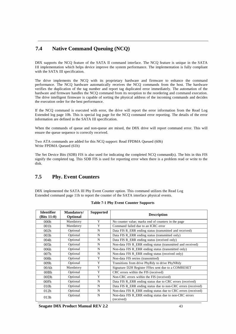
7.4 Native Command Queuing (NCQ) D8X supports the NCQ feature of the SATA II command interface. The NCQ feature is unique in the SATA III implementation which helps device improve the system performance. The implementation is fully compliant with the SATA III specification. The drive implements the NCQ with its proprietary hardware and firmware to enhance the command performance. The NCQ hardware automatically receives the NCQ commands from the host. The hardware verifies the duplication of the tag number and report tag duplicated error immediately. The automation of the hardware and firmware handles the NCQ command from its reception to the reordering and command execution. The drive intelligent firmware is capable of sorting the physical address of the incoming commands and decides the execution order for the best performance. If the NCQ command is executed with error, the drive will report the error information from the Read Log Extended log page 10h. This is special log page for the NCQ command error reporting. The details of the error information are defined in the SATA III specification. When the commands of queue and non-queue are mixed, the D8X drive will report command error. This will ensure the queue sequence is correctly received.
Two ATA commands are added for this NCQ support: Read FPDMA Queued (60h) Write FPDMA Queued (61h) The Set Device Bits (SDB) FIS is also used for indicating the completed NCQ command(s). The bits in this FIS signify the completed tag. This SDB FIS is used for reporting error when there is a problem read or write to the disk. 7.5 Phy. Event Counters D8X implemented the SATA III Phy Event Counter option. This command utilizes the Read Log Extended command page 11h to report the counter of the SATA interface physical events.
Table 7-1 Phy Event Counter Supports
Identifier (Bits 11:0)
Mandatory/ Optional
Supported
Description
000h Mandatory Y No counter value; marks end of counters in the page 001h Mandatory Y Command failed due to an ICRC error 002h Optional N Data FIS R_ERR ending status (transmitted and received) 003h Optional N Data FIS R_ERR ending status (transmitted only) 004h Optional N Data FIS R_ERR ending status (received only) 005h Optional N Non-data FIS R_ERR ending status (transmitted and received) 006h Optional N Non-data FIS R_ERR ending status (transmitted only) 007h Optional N Non-data FIS R_ERR ending status (received only) 008h Optional Y Non-data FIS retries (transmitted) 009h Optional Y Transitions from drive PhyRdy to drive PhyNRdy 00Ah Mandatory Y Signature D2H Register FISes sent due to a COMRESET 00Bh Optional Y CRC errors within the FIS (received) 00Dh Optional Y Non-CRC errors within the FIS (received) 00Fh Optional N Data FIS R_ERR ending status due to CRC errors (received) 010h Optional N Data FIS R_ERR ending status due to non-CRC errors (received) 012h Optional N Non-data FIS R_ERR ending status due to CRC errors (received)
013h Optional N Non-data FIS R_ERR ending status due to non-CRC errors (received)
Seagate D8X Product Manual REV 2.2 43
7.6 Software Settings Preservation
D8X supports SATA III Software Settings Preservation requirements. The settings of the following items will be preserved across device receiving of COMRESET. This will ensure the device operates on the intended settings even if the COMRESET is received. A SATA bus may generates COMRESET on an Asynchronous Signal Loss (ASL) case which may be caused by noise on the bus. The Software Settings Preservation feature can ensure the device continuing its operation on the ASL event.
The settings preserved are as list:
Initialize Device Parameters Power Management Feature Set Security Mode State
o Security Freeze Lock o Security Unlock
Set Address Max (Ext) Set Features
o Write Cache o Set Transfer Mode o Read Look-Ahead
Set Multiple Mode
7.7 SATA Power Management
D8X supports SATA power management from the SATA I, SATA II and SATA III specifications. The SATA power management is designed to conserve interface power usage when the bus is not active. There are two power management requests: PM Partial and PM Slumber. These two states can be requested by either the host or the device. When entering the Partial state, the device is required to exit to normal state in 10 us, while the exit from Slumber state is limited to 10 ms.
The device will respond to the host PM requests and enter the PM mode when requested. The host may request the PM Partial or PM Slumber at and end of command execution.
The device will also issues PM request when this feature is enabled by the host. The host enables the PM feature by a Set Feature command with proper feature data. After the feature is enabled, the device will make a PM request when entering the Standby or Sleep modes.
Seagate D8X Product Manual REV 2.2 44
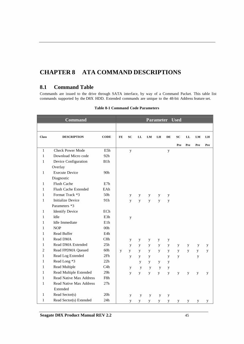
CHAPTER 8 ATA COMMAND DESCRIPTIONS
8.1 Command Table Commands are issued to the drive through SATA interface, by way of a Command Packet. This table list commands supported by the D8X HDD. Extended commands are unique to the 48-bit Address feature set.
Table 8-1 Command Code Parameters
Command
Parameter Used
Class DESCRIPTION CODE
FE SC LL LM LH DE SC LL LM LH
Pre Pre Pre Pre
1 Check Power Mode E5h 1 Download Micro code 92h 1 Device Configuration B1h
Overlay 1 Execute Device 90h
Diagnostic 1 Flush Cache E7h 1 Flush Cache Extended EAh 1 Format Track *3 50h 1 Initialize Device 91h
Parameters *3 1 Identify Device ECh 1 Idle E3h 1 Idle Immediate E1h 1 NOP 00h 1 Read Buffer E4h 1 Read DMA C8h 1 Read DMA Extended 25h 2 Read FPDMA Queued 60h 1 Read Log Extended 2Fh 1 Read Long *3 22h 1 Read Multiple C4h 1 Read Multiple Extended 29h 1 Read Native Max Address F8h 1 Read Native Max Address 27h
Extended 1 Read Sector(s) 20h 1 Read Sector(s) Extended 24h
y y
y y y y y y y y y y
y
y y y y y y y y y y y y y y
y y y y y y y y y y y y y y y y
y y y y y y y y y y y y y y y y y y
y y y y y y y y y y y y y y
Seagate D8X Product Manual REV 2.2 45
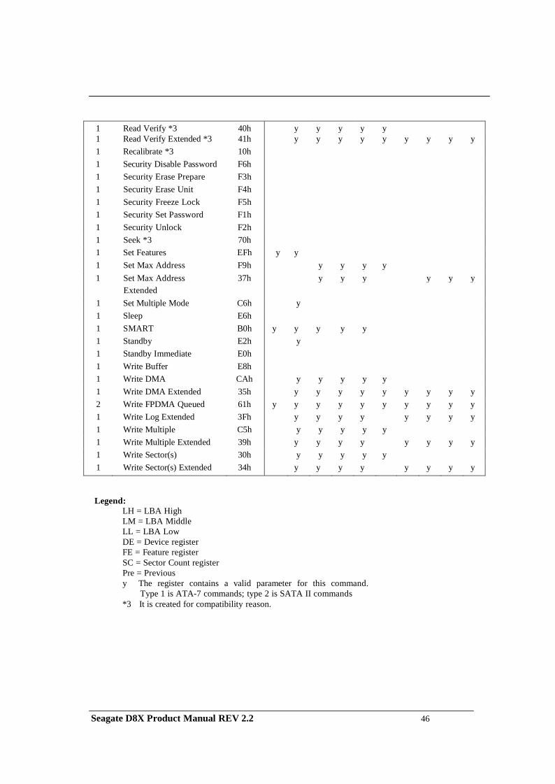
1 Read Verify *3 40h y y y y y 1 Read Verify Extended *3 41h y y y y y y y y y 1 Recalibrate *3 10h 1 Security Disable Password F6h 1 Security Erase Prepare F3h 1 Security Erase Unit F4h 1 Security Freeze Lock F5h 1 Security Set Password F1h 1 Security Unlock F2h 1 Seek *3 70h 1 Set Features EFh y y 1 Set Max Address F9h y y y y 1 Set Max Address 37h y y y y y y
Extended 1 Set Multiple Mode C6h y 1 Sleep E6h 1 SMART B0h y y y y y 1 Standby E2h y 1 Standby Immediate E0h 1 Write Buffer E8h 1 Write DMA CAh y y y y y 1 Write DMA Extended 35h y y y y y y y y y 2 Write FPDMA Queued 61h y y y y y y y y y y 1 Write Log Extended 3Fh y y y y y y y y 1 Write Multiple C5h y y y y y 1 Write Multiple Extended 39h y y y y y y y y 1 Write Sector(s) 30h y y y y y 1 Write Sector(s) Extended 34h y y y y y y y y
Legend: LH = LBA High LM = LBA Middle LL = LBA Low DE = Device register FE = Feature register SC = Sector Count register Pre = Previous y The register contains a valid parameter for this command. Type 1 is ATA-7 commands; type 2 is SATA II commands *3 It is created for compatibility reason.
Seagate D8X Product Manual REV 2.2 46
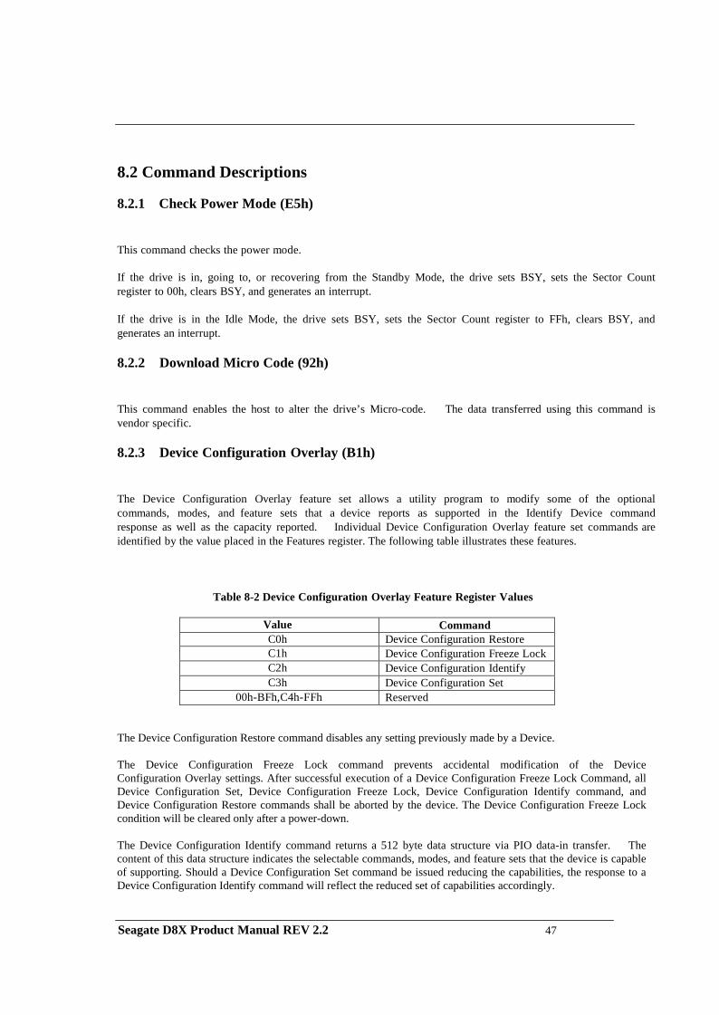
8.2 Command Descriptions
8.2.1 Check Power Mode (E5h)
This command checks the power mode. If the drive is in, going to, or recovering from the Standby Mode, the drive sets BSY, sets the Sector Count register to 00h, clears BSY, and generates an interrupt.
If the drive is in the Idle Mode, the drive sets BSY, sets the Sector Count register to FFh, clears BSY, and generates an interrupt.
8.2.2 Download Micro Code (92h)
This command enables the host to alter the drive’s Micro-code. The data transferred using this command is vendor specific.
8.2.3 Device Configuration Overlay (B1h)
The Device Configuration Overlay feature set allows a utility program to modify some of the optional commands, modes, and feature sets that a device reports as supported in the Identify Device command response as well as the capacity reported. Individual Device Configuration Overlay feature set commands are identified by the value placed in the Features register. The following table illustrates these features.
Table 8-2 Device Configuration Overlay Feature Register Values
Value Command C0h Device Configuration Restore C1h Device Configuration Freeze Lock C2h Device Configuration Identify C3h Device Configuration Set
00h-BFh,C4h-FFh Reserved
The Device Configuration Restore command disables any setting previously made by a Device. The Device Configuration Freeze Lock command prevents accidental modification of the Device Configuration Overlay settings. After successful execution of a Device Configuration Freeze Lock Command, all Device Configuration Set, Device Configuration Freeze Lock, Device Configuration Identify command, and Device Configuration Restore commands shall be aborted by the device. The Device Configuration Freeze Lock condition will be cleared only after a power-down. The Device Configuration Identify command returns a 512 byte data structure via PIO data-in transfer. The content of this data structure indicates the selectable commands, modes, and feature sets that the device is capable of supporting. Should a Device Configuration Set command be issued reducing the capabilities, the response to a Device Configuration Identify command will reflect the reduced set of capabilities accordingly. Seagate D8X Product Manual REV 2.2 47
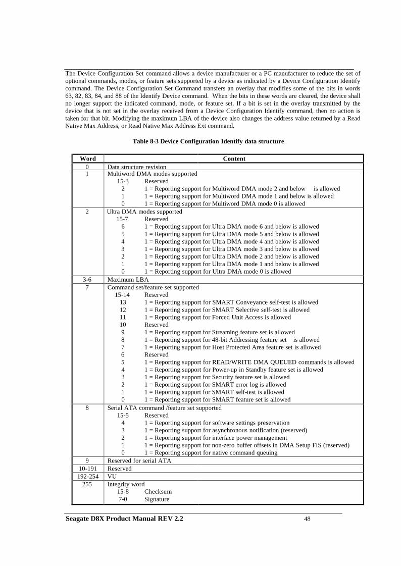
The Device Configuration Set command allows a device manufacturer or a PC manufacturer to reduce the set of optional commands, modes, or feature sets supported by a device as indicated by a Device Configuration Identify command. The Device Configuration Set Command transfers an overlay that modifies some of the bits in words 63, 82, 83, 84, and 88 of the Identify Device command. When the bits in these words are cleared, the device shall no longer support the indicated command, mode, or feature set. If a bit is set in the overlay transmitted by the device that is not set in the overlay received from a Device Configuration Identify command, then no action is taken for that bit. Modifying the maximum LBA of the device also changes the address value returned by a Read Native Max Address, or Read Native Max Address Ext command.
Table 8-3 Device Configuration Identify data structure
Word Content
0 Data structure revision 1 Multiword DMA modes supported
15-3 Reserved 2 1 = Reporting support for Multiword DMA mode 2 and below is allowed 1 1 = Reporting support for Multiword DMA mode 1 and below is allowed 0 1 = Reporting support for Multiword DMA mode 0 is allowed
2 Ultra DMA modes supported 15-7 Reserved
6 1 = Reporting support for Ultra DMA mode 6 and below is allowed 5 1 = Reporting support for Ultra DMA mode 5 and below is allowed 4 1 = Reporting support for Ultra DMA mode 4 and below is allowed 3 1 = Reporting support for Ultra DMA mode 3 and below is allowed 2 1 = Reporting support for Ultra DMA mode 2 and below is allowed 1 1 = Reporting support for Ultra DMA mode 1 and below is allowed 0 1 = Reporting support for Ultra DMA mode 0 is allowed
3-6 Maximum LBA 7 Command set/feature set supported
15-14 Reserved 13 1 = Reporting support for SMART Conveyance self-test is allowed 12 1 = Reporting support for SMART Selective self-test is allowed 11 1 = Reporting support for Forced Unit Access is allowed 10 Reserved 9 1 = Reporting support for Streaming feature set is allowed 8 1 = Reporting support for 48-bit Addressing feature set is allowed 7 1 = Reporting support for Host Protected Area feature set is allowed 6 Reserved 5 1 = Reporting support for READ/WRITE DMA QUEUED commands is allowed 4 1 = Reporting support for Power-up in Standby feature set is allowed 3 1 = Reporting support for Security feature set is allowed 2 1 = Reporting support for SMART error log is allowed 1 1 = Reporting support for SMART self-test is allowed 0 1 = Reporting support for SMART feature set is allowed
8 Serial ATA command /feature set supported 15-5 Reserved
4 1 = Reporting support for software settings preservation 3 1 = Reporting support for asynchronous notification (reserved) 2 1 = Reporting support for interface power management 1 1 = Reporting support for non-zero buffer offsets in DMA Setup FIS (reserved) 0 1 = Reporting support for native command queuing
9 Reserved for serial ATA 10-191 Reserved
192-254 VU 255 Integrity word
15-8 Checksum 7-0 Signature
Seagate D8X Product Manual REV 2.2 48
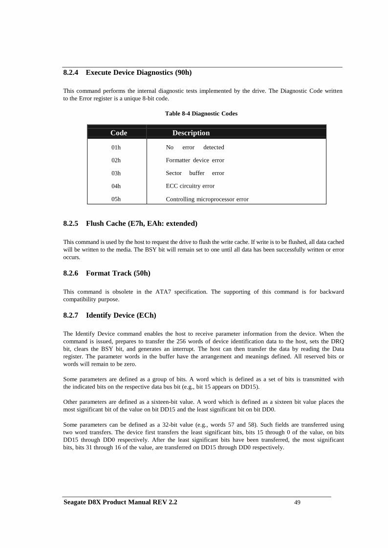
8.2.4 Execute Device Diagnostics (90h)
This command performs the internal diagnostic tests implemented by the drive. The Diagnostic Code written to the Error register is a unique 8-bit code.
Table 8-4 Diagnostic Codes
Code
Description
01h
02h
03h
04h
05h
No error detected
Formatter device error
Sector buffer error
ECC circuitry error
Controlling microprocessor error
8.2.5 Flush Cache (E7h, EAh: extended)
This command is used by the host to request the drive to flush the write cache. If write is to be flushed, all data cached will be written to the media. The BSY bit will remain set to one until all data has been successfully written or error occurs.
8.2.6 Format Track (50h)
This command is obsolete in the ATA7 specification. The supporting of this command is for backward compatibility purpose.
8.2.7 Identify Device (ECh)
The Identify Device command enables the host to receive parameter information from the device. When the command is issued, prepares to transfer the 256 words of device identification data to the host, sets the DRQ bit, clears the BSY bit, and generates an interrupt. The host can then transfer the data by reading the Data register. The parameter words in the buffer have the arrangement and meanings defined. All reserved bits or words will remain to be zero.
Some parameters are defined as a group of bits. A word which is defined as a set of bits is transmitted with the indicated bits on the respective data bus bit (e.g., bit 15 appears on DD15).
Other parameters are defined as a sixteen-bit value. A word which is defined as a sixteen bit value places the most significant bit of the value on bit DD15 and the least significant bit on bit DD0.
Some parameters can be defined as a 32-bit value (e.g., words 57 and 58). Such fields are transferred using two word transfers. The device first transfers the least significant bits, bits 15 through 0 of the value, on bits DD15 through DD0 respectively. After the least significant bits have been transferred, the most significant bits, bits 31 through 16 of the value, are transferred on DD15 through DD0 respectively.
Seagate D8X Product Manual REV 2.2 49
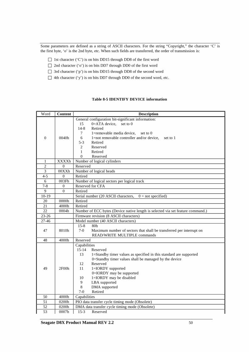
Some parameters are defined as a string of ASCII characters. For the string “Copyright,” the character ‘C’ is the first byte, ‘o’ is the 2nd byte, etc. When such fields are transferred, the order of transmission is:
1st character (‘C’) is on bits DD15 through DD8 of the first word 2nd character (‘o’) is on bits DD7 through DD0 of the first word 3rd character (‘p’) is on bits DD15 through DD8 of the second word 4th character (‘y’) is on bits DD7 through DD0 of the second word, etc.
Table 8-5 IDENTIFY DEVICE information
Word Content Description
0
0040h
General configuration bit-significant information: 15 0=ATA device, set to 0
14-8 Retired 7 1=removable media device, set to 0 6 1=not removable controller and/or device, set to 1
5-3 Retired 2 Reserved 1 Retired 0 Reserved
1 XXXXh Number of logical cylinders 2 0 Reserved 3 00XXh Number of logical heads
4-5 0 Retired 6 003Fh Number of logical sectors per logical track
7-8 0 Reserved for CFA 9 0 Retired
10-19 Serial number (20 ASCII characters, 0 = not specified) 20 0000h Retired 21 4000h Retired 22 0004h Number of ECC bytes (Device native length is selected via set feature command.)
23-26 Firmware revision (8 ASCII characters) 27-46 Model number (40 ASCII characters)
47
8010h
15-8 80h 7-0 Maximum number of sectors that shall be transferred per interrupt on
READ/WRITE MULTIPLE commands 48 4000h Reserved
49
2F00h
Capabilities 15-14 Reserved
13 1=Standby timer values as specified in this standard are supported 0=Standby timer values shall be managed by the device
12 Reserved 11 1=IORDY supported
0=IORDY may be supported 10 1=IORDY may be disabled 9 LBA supported 8 DMA supported
7-0 Retired 50 4000h Capabilities 51 0200h PIO data transfer cycle timing mode (Obsolete) 52 0200h DMA data transfer cycle timing mode (Obsolete) 53 0007h 15-3 Reserved
Seagate D8X Product Manual REV 2.2 50
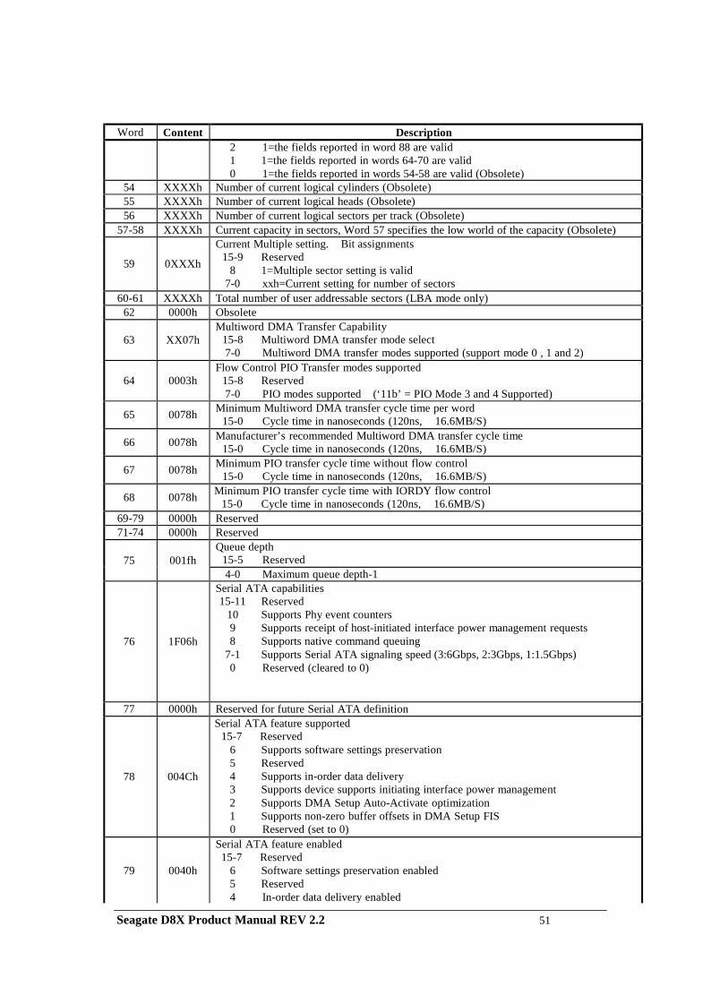
Word Content Description 2 1=the fields reported in word 88 are valid
1 1=the fields reported in words 64-70 are valid 0 1=the fields reported in words 54-58 are valid (Obsolete)
54 XXXXh Number of current logical cylinders (Obsolete) 55 XXXXh Number of current logical heads (Obsolete) 56 XXXXh Number of current logical sectors per track (Obsolete)
57-58 XXXXh Current capacity in sectors, Word 57 specifies the low world of the capacity (Obsolete)
59
0XXXh
Current Multiple setting. Bit assignments 15-9 Reserved
8 1=Multiple sector setting is valid 7-0 xxh=Current setting for number of sectors
60-61 XXXXh Total number of user addressable sectors (LBA mode only) 62 0000h Obsolete
63
XX07h
Multiword DMA Transfer Capability 15-8 Multiword DMA transfer mode select 7-0 Multiword DMA transfer modes supported (support mode 0 , 1 and 2)
64
0003h
Flow Control PIO Transfer modes supported 15-8 Reserved 7-0 PIO modes supported (‘11b’ = PIO Mode 3 and 4 Supported)
65
0078h Minimum Multiword DMA transfer cycle time per word 15-0 Cycle time in nanoseconds (120ns, 16.6MB/S)
66
0078h Manufacturer’s recommended Multiword DMA transfer cycle time 15-0 Cycle time in nanoseconds (120ns, 16.6MB/S)
67
0078h Minimum PIO transfer cycle time without flow control 15-0 Cycle time in nanoseconds (120ns, 16.6MB/S)
68
0078h Minimum PIO transfer cycle time with IORDY flow control 15-0 Cycle time in nanoseconds (120ns, 16.6MB/S)
69-79 0000h Reserved 71-74 0000h Reserved
75
001fh
Queue depth 15-5 Reserved 4-0 Maximum queue depth-1
76
1F06h
Serial ATA capabilities 15-11 Reserved
10 Supports Phy event counters 9 Supports receipt of host-initiated interface power management requests 8 Supports native command queuing
7-1 Supports Serial ATA signaling speed (3:6Gbps, 2:3Gbps, 1:1.5Gbps) 0 Reserved (cleared to 0)
77 0000h Reserved for future Serial ATA definition
78
004Ch
Serial ATA feature supported 15-7 Reserved
6 Supports software settings preservation 5 Reserved 4 Supports in-order data delivery 3 Supports device supports initiating interface power management 2 Supports DMA Setup Auto-Activate optimization 1 Supports non-zero buffer offsets in DMA Setup FIS 0 Reserved (set to 0)
79
0040h
Serial ATA feature enabled 15-7 Reserved
6 Software settings preservation enabled 5 Reserved 4 In-order data delivery enabled
Seagate D8X Product Manual REV 2.2 51
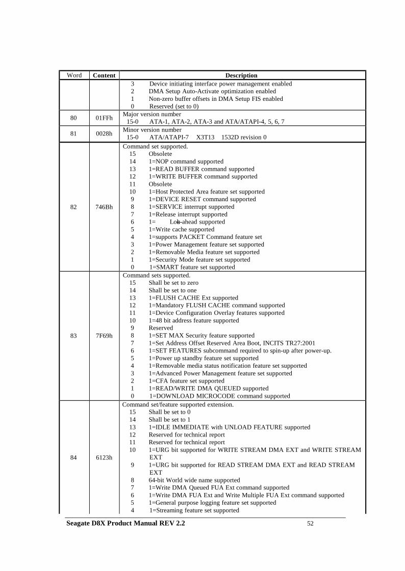
Word Content Description 3 Device initiating interface power management enabled
2 DMA Setup Auto-Activate optimization enabled 1 Non-zero buffer offsets in DMA Setup FIS enabled 0 Reserved (set to 0)
80
01FFh Major version number 15-0 ATA-1, ATA-2, ATA-3 and ATA/ATAPI-4, 5, 6, 7
81
0028h Minor version number 15-0 ATA/ATAPI-7 X3T13 1532D revision 0
82
746Bh
Command set supported. 15 Obsolete 14 1=NOP command supported 13 1=READ BUFFER command supported 12 1=WRITE BUFFER command supported 11 Obsolete 10 1=Host Protected Area feature set supported 9 1=DEVICE RESET command supported 8 1=SERVICE interrupt supported 7 1=Release interrupt supported 6 1= Look-ahead supported 5 1=Write cache supported 4 1=supports PACKET Command feature set 3 1=Power Management feature set supported 2 1=Removable Media feature set supported 1 1=Security Mode feature set supported 0 1=SMART feature set supported
83
7F69h
Command sets supported. 15 Shall be set to zero 14 Shall be set to one 13 1=FLUSH CACHE Ext supported 12 1=Mandatory FLUSH CACHE command supported 11 1=Device Configuration Overlay features supported 10 1=48 bit address feature supported 9 Reserved 8 1=SET MAX Security feature supported 7 1=Set Address Offset Reserved Area Boot, INCITS TR27:2001 6 1=SET FEATURES subcommand required to spin-up after power-up. 5 1=Power up standby feature set supported 4 1=Removable media status notification feature set supported 3 1=Advanced Power Management feature set supported 2 1=CFA feature set supported 1 1=READ/WRITE DMA QUEUED supported 0 1=DOWNLOAD MICROCODE command supported
84
6123h
Command set/feature supported extension. 15 Shall be set to 0 14 Shall be set to 1 13 1=IDLE IMMEDIATE with UNLOAD FEATURE supported 12 Reserved for technical report 11 Reserved for technical report 10 1=URG bit supported for WRITE STREAM DMA EXT and WRITE STREAM
EXT 9 1=URG bit supported for READ STREAM DMA EXT and READ STREAM
EXT 8 64-bit World wide name supported 7 1=Write DMA Queued FUA Ext command supported 6 1=Write DMA FUA Ext and Write Multiple FUA Ext command supported 5 1=General purpose logging feature set supported 4 1=Streaming feature set supported
Seagate D8X Product Manual REV 2.2 52
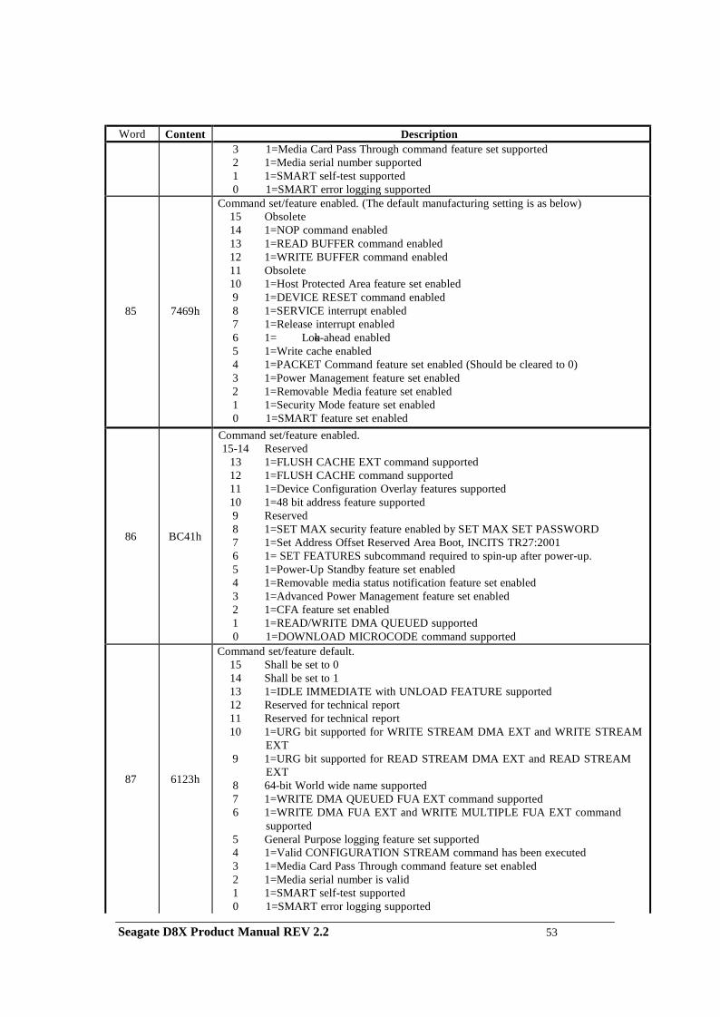
Word Content Description 3 1=Media Card Pass Through command feature set supported
2 1=Media serial number supported 1 1=SMART self-test supported 0 1=SMART error logging supported
85
7469h
Command set/feature enabled. (The default manufacturing setting is as below) 15 Obsolete 14 1=NOP command enabled 13 1=READ BUFFER command enabled 12 1=WRITE BUFFER command enabled 11 Obsolete 10 1=Host Protected Area feature set enabled 9 1=DEVICE RESET command enabled 8 1=SERVICE interrupt enabled 7 1=Release interrupt enabled 6 1= Look-ahead enabled 5 1=Write cache enabled 4 1=PACKET Command feature set enabled (Should be cleared to 0) 3 1=Power Management feature set enabled 2 1=Removable Media feature set enabled 1 1=Security Mode feature set enabled 0 1=SMART feature set enabled
86
BC41h
Command set/feature enabled. 15-14 Reserved
13 1=FLUSH CACHE EXT command supported 12 1=FLUSH CACHE command supported 11 1=Device Configuration Overlay features supported 10 1=48 bit address feature supported 9 Reserved 8 1=SET MAX security feature enabled by SET MAX SET PASSWORD 7 1=Set Address Offset Reserved Area Boot, INCITS TR27:2001 6 1= SET FEATURES subcommand required to spin-up after power-up. 5 1=Power-Up Standby feature set enabled 4 1=Removable media status notification feature set enabled 3 1=Advanced Power Management feature set enabled 2 1=CFA feature set enabled 1 1=READ/WRITE DMA QUEUED supported 0 1=DOWNLOAD MICROCODE command supported
87
6123h
Command set/feature default. 15 Shall be set to 0 14 Shall be set to 1 13 1=IDLE IMMEDIATE with UNLOAD FEATURE supported 12 Reserved for technical report 11 Reserved for technical report 10 1=URG bit supported for WRITE STREAM DMA EXT and WRITE STREAM
EXT 9 1=URG bit supported for READ STREAM DMA EXT and READ STREAM
EXT 8 64-bit World wide name supported 7 1=WRITE DMA QUEUED FUA EXT command supported 6 1=WRITE DMA FUA EXT and WRITE MULTIPLE FUA EXT command
supported 5 General Purpose logging feature set supported 4 1=Valid CONFIGURATION STREAM command has been executed 3 1=Media Card Pass Through command feature set enabled 2 1=Media serial number is valid 1 1=SMART self-test supported 0 1=SMART error logging supported
Seagate D8X Product Manual REV 2.2 53
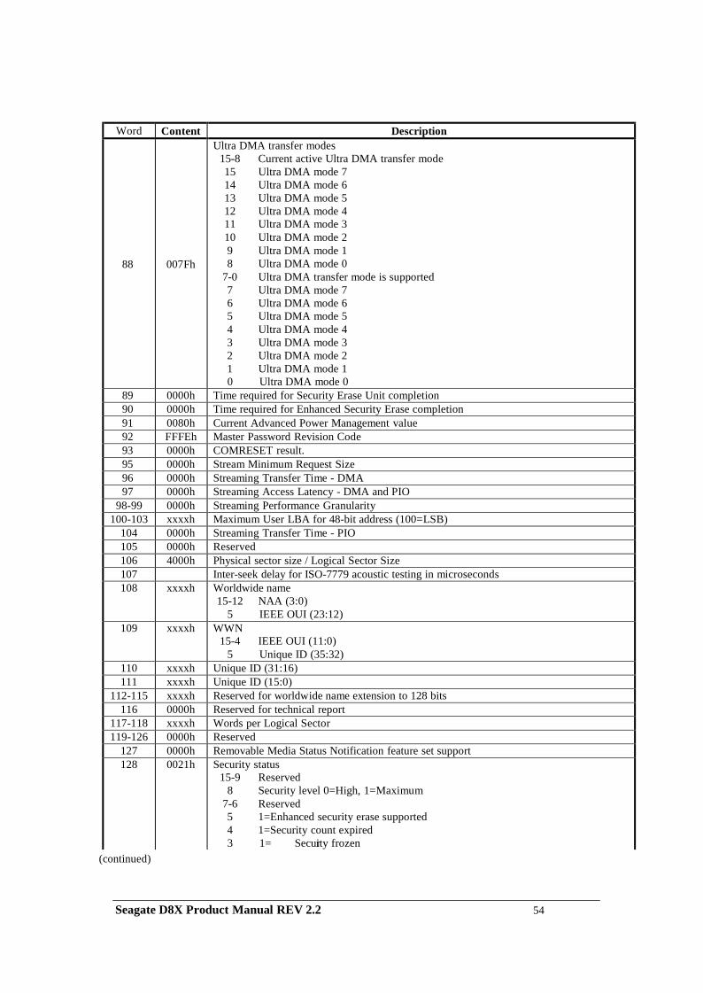
Word Content Description
88
007Fh
Ultra DMA transfer modes 15-8 Current active Ultra DMA transfer mode 15 Ultra DMA mode 7 14 Ultra DMA mode 6 13 Ultra DMA mode 5 12 Ultra DMA mode 4 11 Ultra DMA mode 3 10 Ultra DMA mode 2 9 Ultra DMA mode 1 8 Ultra DMA mode 0
7-0 Ultra DMA transfer mode is supported 7 Ultra DMA mode 7 6 Ultra DMA mode 6 5 Ultra DMA mode 5 4 Ultra DMA mode 4 3 Ultra DMA mode 3 2 Ultra DMA mode 2 1 Ultra DMA mode 1 0 Ultra DMA mode 0
89 0000h Time required for Security Erase Unit completion 90 0000h Time required for Enhanced Security Erase completion 91 0080h Current Advanced Power Management value 92 FFFEh Master Password Revision Code 93 0000h COMRESET result. 95 0000h Stream Minimum Request Size 96 0000h Streaming Transfer Time - DMA 97 0000h Streaming Access Latency - DMA and PIO
98-99 0000h Streaming Performance Granularity 100-103 xxxxh Maximum User LBA for 48-bit address (100=LSB)
104 0000h Streaming Transfer Time - PIO 105 0000h Reserved 106 4000h Physical sector size / Logical Sector Size 107 Inter-seek delay for ISO-7779 acoustic testing in microseconds 108 xxxxh Worldwide name
15-12 NAA (3:0) 5 IEEE OUI (23:12)
109 xxxxh WWN 15-4 IEEE OUI (11:0)
5 Unique ID (35:32) 110 xxxxh Unique ID (31:16) 111 xxxxh Unique ID (15:0)
112-115 xxxxh Reserved for worldwide name extension to 128 bits 116 0000h Reserved for technical report
117-118 xxxxh Words per Logical Sector 119-126 0000h Reserved
127 0000h Removable Media Status Notification feature set support 128 0021h Security status
15-9 Reserved 8 Security level 0=High, 1=Maximum
7-6 Reserved 5 1=Enhanced security erase supported 4 1=Security count expired 3 1= Security frozen
(continued)
Seagate D8X Product Manual REV 2.2 54
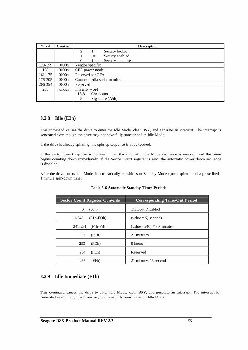
Word Content Description 2 1= Security locked
1 1= Security enabled 0 1= Security supported
129-159 0000h Vendor specific 160 0000h CFA power mode 1
161-175 0000h Reserved for CFA 176-205 0000h Current media serial number 206-254 0000h Reserved
255 xxxxh Integrity word 15-8 Checksum
5 Signature (A5h)
8.2.8 Idle (E3h)
This command causes the drive to enter the Idle Mode, clear BSY, and generate an interrupt. The interrupt is generated even though the drive may not have fully transitioned to Idle Mode.
If the drive is already spinning, the spin-up sequence is not executed.
If the Sector Count register is non-zero, then the automatic Idle Mode sequence is enabled, and the timer begins counting down immediately. If the Sector Count register is zero, the automatic power down sequence is disabled.
After the drive enters Idle Mode, it automatically transitions to Standby Mode upon expiration of a prescribed 1 minute spin-down timer.
Table 8-6 Automatic Standby Timer Periods
Sector Count Register Contents
Corresponding Time-Out Period
0 (00h)
Timeout Disabled
1-240 (01h-FOh)
(value * 5) seconds
241-251 (F1h-FBh)
(value - 240) * 30 minutes
252 (FCh)
21 minutes
253 (FDh)
8 hours
254 (FEh)
Reserved
255 (FFh)
21 minutes 15 seconds
8.2.9 Idle Immediate (E1h)
This command causes the drive to enter Idle Mode, clear BSY, and generate an interrupt. The interrupt is generated even though the drive may not have fully transitioned to Idle Mode.
Seagate D8X Product Manual REV 2.2 55
8.2.10 Initialize Device Parameters (91h)
This command is obsolete in the ATA7 specification. The supporting of this command is for backward compatibility purpose. The use of this command is beyond the ATA standard and not recommended by the manufacture.
This command enables the host to set the number of sectors per track and the number of heads minus 1, per cylinder. Upon receipt of the command, the drive sets BSY, saves the parameters, clears BSY, and generates an interrupt.
The only two register values used by this command are the Sector Count register which specifies the number of sectors per track, and the Drive/Head register which specifies the number of heads minus 1. The sector count and head values are not checked for validity by this command. If they are invalid, no error will be posted until an illegal access is made by some other command.
8.2.11 NOP (00h)
The NOP command is always responded with command aborted.
8.2.12 Read Buffer (E4h)
The Read Buffer command enables the host to read the current contents of the drive's sector buffer. When this command is issued, the drive sets up the sector buffer for a read operation, sets DRQ, clears BSY, and generates an interrupt. The host then reads up to 512 bytes of data from the buffer.
The Read Buffer and Write Buffer commands are synchronized so that sequential Write Buffer (E8h) and Read Buffer commands access the same 512 bytes within the buffer.
8.2.13 Read DMA (C8h, 25h: extended)
This command executes in a manner similar to the Read Sector(s) command except for the drive issues only one interrupt per command to indicate that data transfer has stopped and the status is available.
Any unrecoverable error encountered during execution of a Read DMA command results in the termination of data transfer prior to the sector where the error was detected. The drive generates an interrupt to indicate that data transfer has terminated and status is available. The error posting is the same as that for the Read Sector(s) command.
8.2.14 Read FPDMA Queued (60h)
This command is implemented according to the Serial ATA II: Extension to Serial ATA 1.0a, Revision 1.2 specification. The purpose of this command is for the host to issue a Native Command Queue (NCQ) read commands. This command allows device to reorder the command issued in a sequence of the queue. The command is returned based on the device’s determine of the location sequence.
The D8X drive implemented a queue depth of 32. This will allow host to issue up to 32 NCQ commands (combined read and write commands).
Seagate D8X Product Manual REV 2.2 56
If the drive enters NCQ mode and a non-queue command is received, the drive will respond with error to inform host a queue command been overlapped with non-queue. If a queue tag is not finished and another same tag command is received, the drive will response with error to inform host a duplicated tag is received.
Error information is reported according to the SATA III specification. A read Log Extended command with log page 10 is required to retrieve the error information.
8.2.15 Read Log Extended (2Fh)
This command returns the specified log to the host. The device shall interrupt for each DRQ block transferred. See ATA 7 document for command details.
8.2.16 Read Long (22h)
This command is obsolete in the ATA7 specification. The supporting of this command is for backward compatibility purpose. The use of this command is beyond the ATA standard and not recommended by the manufacture.
The Read Long command performs similarly to the Read Sectors command except that it returns the data and the ECC bytes appended to the data field of the desired sector. During a Read Long command, the drive does not check the ECC bytes to determine if there has been a data error. Only single sector Read Long operations are supported.
The transfer of the ECC bytes shall be 8 bits wide and 4 or device native ECC bytes length.
8.2.17 Read Multiple Command (C4h, 29h: extended) The Read Multiple command performs similarly to the Read Sectors command except interrupts are not generated on every sector, but on the transfer of a block which contains the number of sectors defined by a Set Multiple command.
Command execution is identical to the Read Sectors operation except that the numbers of sectors as defined by a Set of Multiple command are transferred without intervening interrupts. DRQ qualification of the transfer is required only at the start of the data block, not on each sector.
The block count of sectors to be transferred without intervening interrupts is programmed by the Set Multiple Mode command, which should be executed prior to the Read Multiple command. When the Read Multiple command is issued, the Sector Count register contains the number of sectors (not the number of blocks or the block count) requested.
If the number of requested sectors is not evenly divisible by the block count, as many full blocks as possible are transferred, followed by a final, partial block transfer. The partial block transfer shall be for n sectors, where
n = Remainder (Sector Count / Block Count)
If the Read Multiple command is attempted before the Set Multiple Mode command has been executed or when Read Multiple commands are disabled, then the Read Multiple operation is rejected with an Aborted Command error.
Disk errors encountered during Read Multiple commands are posted at the beginning of the block or partial block transfer, but DRQ is still set and the data transfer takes place as it normally would, including transfer of corrupted data, if any.
Seagate D8X Product Manual REV 2.2 57
The contents of the Command Block registers, following the transfer of a data block, which had a sector in error, are undefined. The host should retry the transfer as individual requests to obtain valid error information.
Subsequent blocks are transferred only if the error was a correctable data error. All other errors cause the command to stop after transfer of the block, which contained the error. Interrupts are generated when DRQ is set at the beginning of each block.
8.2.18 Read Native Max Address (F8h, 27h: extended)
This command returns the native maximum address. The native maximum address is the highest address accepted by the device in the factory default condition. The native maximum address is the maximum address that is valid when using the SET MAX ADDRESS command.
8.2.19 Read Sector(s) (20h, 24h: extended)
This command reads from 1 to 256 sectors as specified in the Sector Count register. A sector counts of 0 requests all 256 sectors if the command is Read Sectors (not Read Sector Extended). The transfer begins at the sector specified in the Sector Number register.
If the drive is not already on the desired track, an implied seek is performed. Once at the desired track, the drive searches for the appropriate ID field.
If the ID is read correctly, the data address mark shall be recognized within a specified number of bytes, or the Address Mark Not Found error is posted. DRQ is always set prior to data transfer, regardless of the presence or absence of an error condition.
At command completion, the Command Block registers contain the address of the last sector read. If an error occurs, the read terminates at the sector where the error occurred. The Command Block registers contain the address of the sector where the error occurred.
8.2.20 Read Verify Sector(s) (40h, 41h: extended)
This command is obsolete in the ATA7 specification. The supporting of this command is for backward compatibility purpose. The use of this command is beyond the ATA standard and not recommended by the manufacturer.
This command is identical to the Read Sectors command, except that DRQ is never set, and no data is transferred to the host.
When the requested sectors have been verified, the drive clears BSY and generates an interrupt. Upon command completion, the Command Block registers contain the address of the last sector verified. If an error occurs, the Verify terminates at the sector where the error occurred.
The Command Block registers contain the address of where the error occurred. The Sector Count register contains the number of sectors not yet verified.
Seagate D8X Product Manual REV 2.2 58
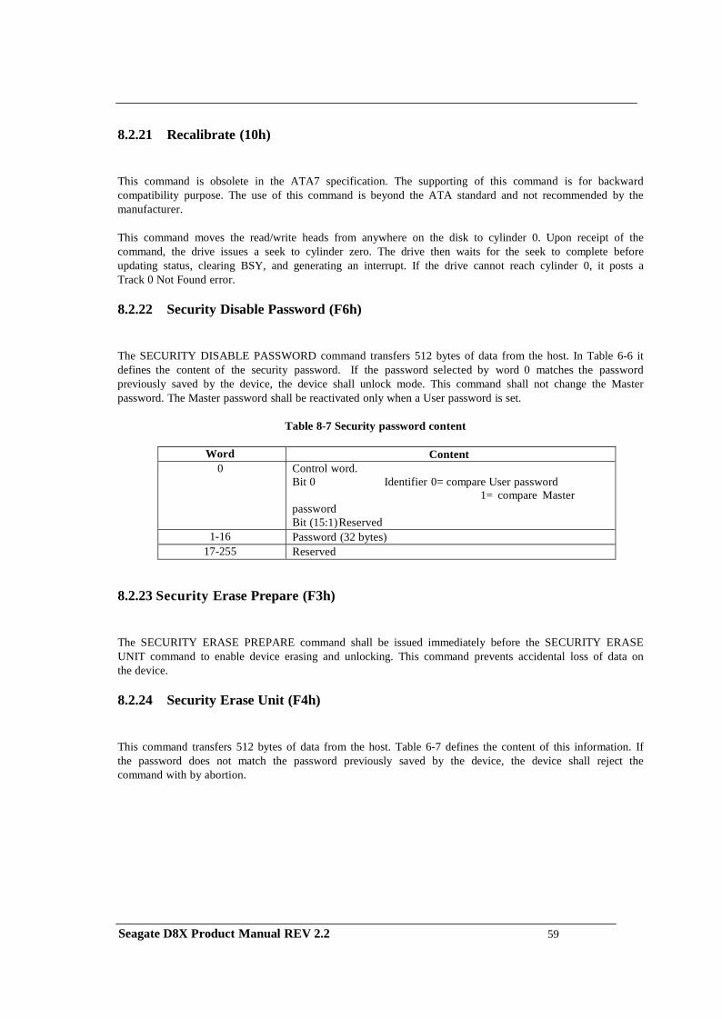
8.2.21 Recalibrate (10h)
This command is obsolete in the ATA7 specification. The supporting of this command is for backward compatibility purpose. The use of this command is beyond the ATA standard and not recommended by the manufacturer.
This command moves the read/write heads from anywhere on the disk to cylinder 0. Upon receipt of the command, the drive issues a seek to cylinder zero. The drive then waits for the seek to complete before updating status, clearing BSY, and generating an interrupt. If the drive cannot reach cylinder 0, it posts a Track 0 Not Found error.
8.2.22 Security Disable Password (F6h)
The SECURITY DISABLE PASSWORD command transfers 512 bytes of data from the host. In Table 6-6 it defines the content of the security password. If the password selected by word 0 matches the password previously saved by the device, the device shall unlock mode. This command shall not change the Master password. The Master password shall be reactivated only when a User password is set.
Table 8-7 Security password content
Word Content
0 Control word. Bit 0 Identifier 0= compare User password
1= compare Master password Bit (15:1) Reserved
1-16 Password (32 bytes) 17-255 Reserved
8.2.23 Security Erase Prepare (F3h)
The SECURITY ERASE PREPARE command shall be issued immediately before the SECURITY ERASE UNIT command to enable device erasing and unlocking. This command prevents accidental loss of data on the device.
8.2.24 Security Erase Unit (F4h)
This command transfers 512 bytes of data from the host. Table 6-7 defines the content of this information. If the password does not match the password previously saved by the device, the device shall reject the command with by abortion.
Seagate D8X Product Manual REV 2.2 59
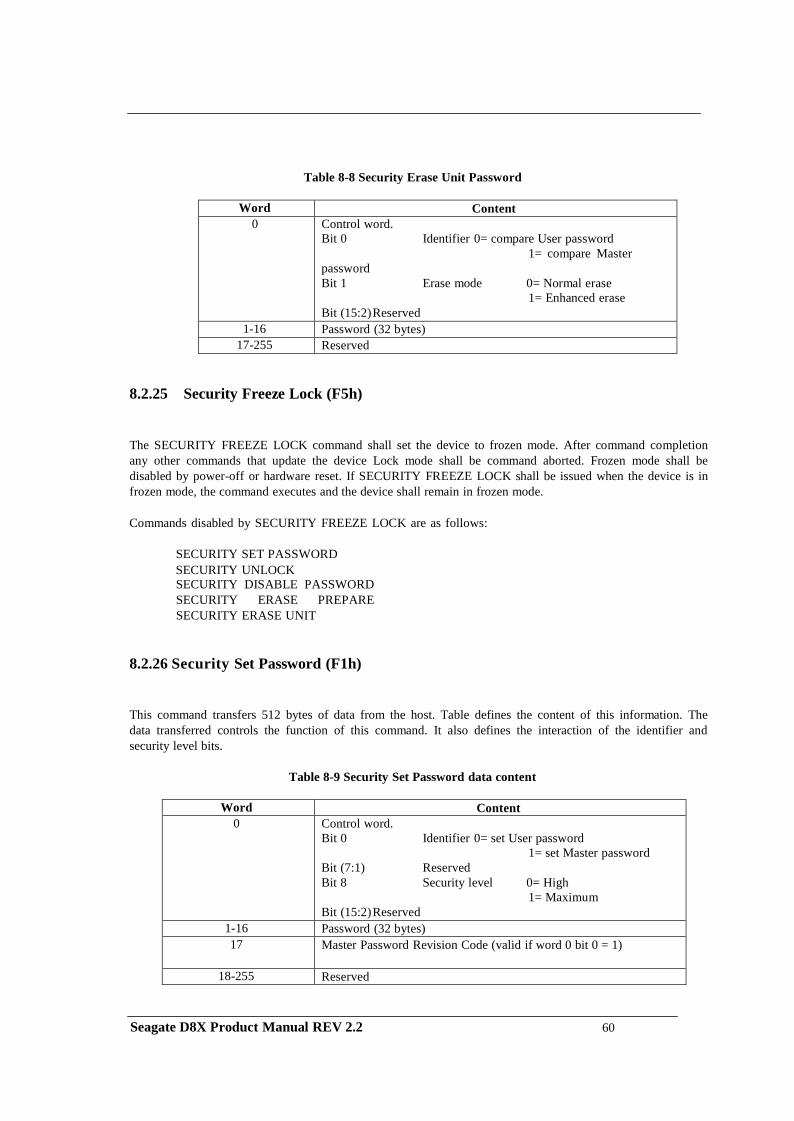
Table 8-8 Security Erase Unit Password
Word Content 0 Control word.
Bit 0 Identifier 0= compare User password 1= compare Master
password Bit 1 Erase mode 0= Normal erase
1= Enhanced erase Bit (15:2) Reserved
1-16 Password (32 bytes) 17-255 Reserved
8.2.25 Security Freeze Lock (F5h)
The SECURITY FREEZE LOCK command shall set the device to frozen mode. After command completion any other commands that update the device Lock mode shall be command aborted. Frozen mode shall be disabled by power-off or hardware reset. If SECURITY FREEZE LOCK shall be issued when the device is in frozen mode, the command executes and the device shall remain in frozen mode.
Commands disabled by SECURITY FREEZE LOCK are as follows:
SECURITY SET PASSWORD SECURITY UNLOCK SECURITY DISABLE PASSWORD SECURITY ERASE PREPARE SECURITY ERASE UNIT
8.2.26 Security Set Password (F1h)
This command transfers 512 bytes of data from the host. Table defines the content of this information. The data transferred controls the function of this command. It also defines the interaction of the identifier and security level bits.
Table 8-9 Security Set Password data content
Word Content
0 Control word. Bit 0 Identifier 0= set User password
1= set Master password Bit (7:1) Reserved Bit 8 Security level 0= High
1= Maximum Bit (15:2) Reserved
1-16 Password (32 bytes) 17 Master Password Revision Code (valid if word 0 bit 0 = 1)
18-255 Reserved
Seagate D8X Product Manual REV 2.2 60
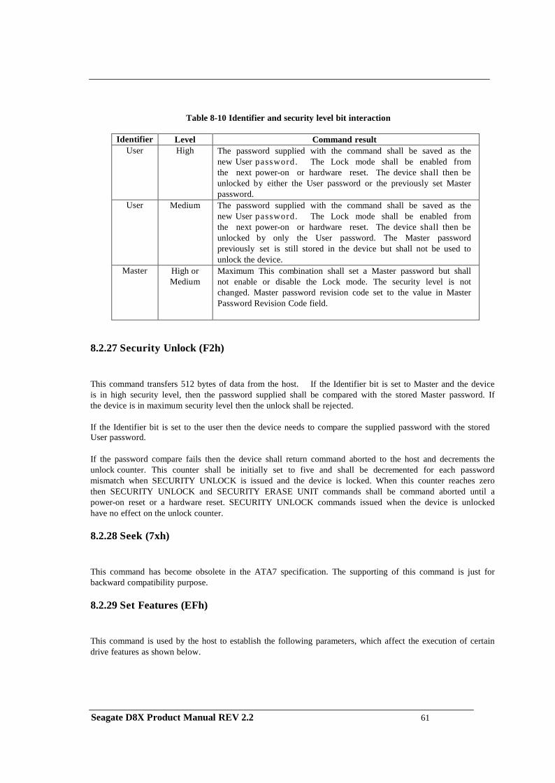
Table 8-10 Identifier and security level bit interaction
Identifier Level Command result
User High The password supplied with the command shall be saved as the new User password. The Lock mode shall be enabled from the next power-on or hardware reset. The device shall then be unlocked by either the User password or the previously set Master password.
User Medium The password supplied with the command shall be saved as the new User password. The Lock mode shall be enabled from the next power-on or hardware reset. The device shall then be unlocked by only the User password. The Master password previously set is still stored in the device but shall not be used to unlock the device.
Master High or Medium
Maximum This combination shall set a Master password but shall not enable or disable the Lock mode. The security level is not changed. Master password revision code set to the value in Master Password Revision Code field.
8.2.27 Security Unlock (F2h)
This command transfers 512 bytes of data from the host. If the Identifier bit is set to Master and the device is in high security level, then the password supplied shall be compared with the stored Master password. If the device is in maximum security level then the unlock shall be rejected.
If the Identifier bit is set to the user then the device needs to compare the supplied password with the stored User password.
If the password compare fails then the device shall return command aborted to the host and decrements the unlock counter. This counter shall be initially set to five and shall be decremented for each password mismatch when SECURITY UNLOCK is issued and the device is locked. When this counter reaches zero then SECURITY UNLOCK and SECURITY ERASE UNIT commands shall be command aborted until a power-on reset or a hardware reset. SECURITY UNLOCK commands issued when the device is unlocked have no effect on the unlock counter.
8.2.28 Seek (7xh)
This command has become obsolete in the ATA7 specification. The supporting of this command is just for backward compatibility purpose.
8.2.29 Set Features (EFh)
This command is used by the host to establish the following parameters, which affect the execution of certain drive features as shown below.
Seagate D8X Product Manual REV 2.2 61
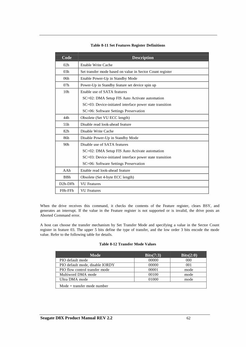
Table 8-11 Set Features Register Definitions
Code
Description
02h Enable Write Cache
03h Set transfer mode based on value in Sector Count register
06h Enable Power-Up in Standby Mode
07h Power-Up in Standby feature set device spin up
10h Enable use of SATA features SC=02: DMA Setup FIS Auto Activate automation SC=03: Device-initiated interface power state transition
SC=06: Software Settings Preservation
44h Obsolete (Set VU ECC length)
55h Disable read look-ahead feature
82h Disable Write Cache
86h Disable Power-Up in Standby Mode
90h Disable use of SATA features SC=02: DMA Setup FIS Auto Activate automation SC=03: Device-initiated interface power state transition
SC=06: Software Settings Preservation
AAh Enable read look-ahead feature
BBh Obsolete (Set 4-byte ECC length)
D2h-DFh VU Features
F0h-FFh VU Features
When the drive receives this command, it checks the contents of the Feature register, clears BSY, and generates an interrupt. If the value in the Feature register is not supported or is invalid, the drive posts an Aborted Command error.
A host can choose the transfer mechanism by Set Transfer Mode and specifying a value in the Sector Count register in feature 03. The upper 5 bits define the type of transfer, and the low order 3 bits encode the mode value. Refer to the following table for details.
Table 8-12 Transfer Mode Values
Mode Bits(7:3) Bits(2:0)
PIO default mode 00000 000 PIO default mode, disable IORDY 00000 001 PIO flow control transfer mode 00001 mode Multiword DMA mode 00100 mode Ultra DMA mode 01000 mode
Mode = transfer mode number
Seagate D8X Product Manual REV 2.2 62
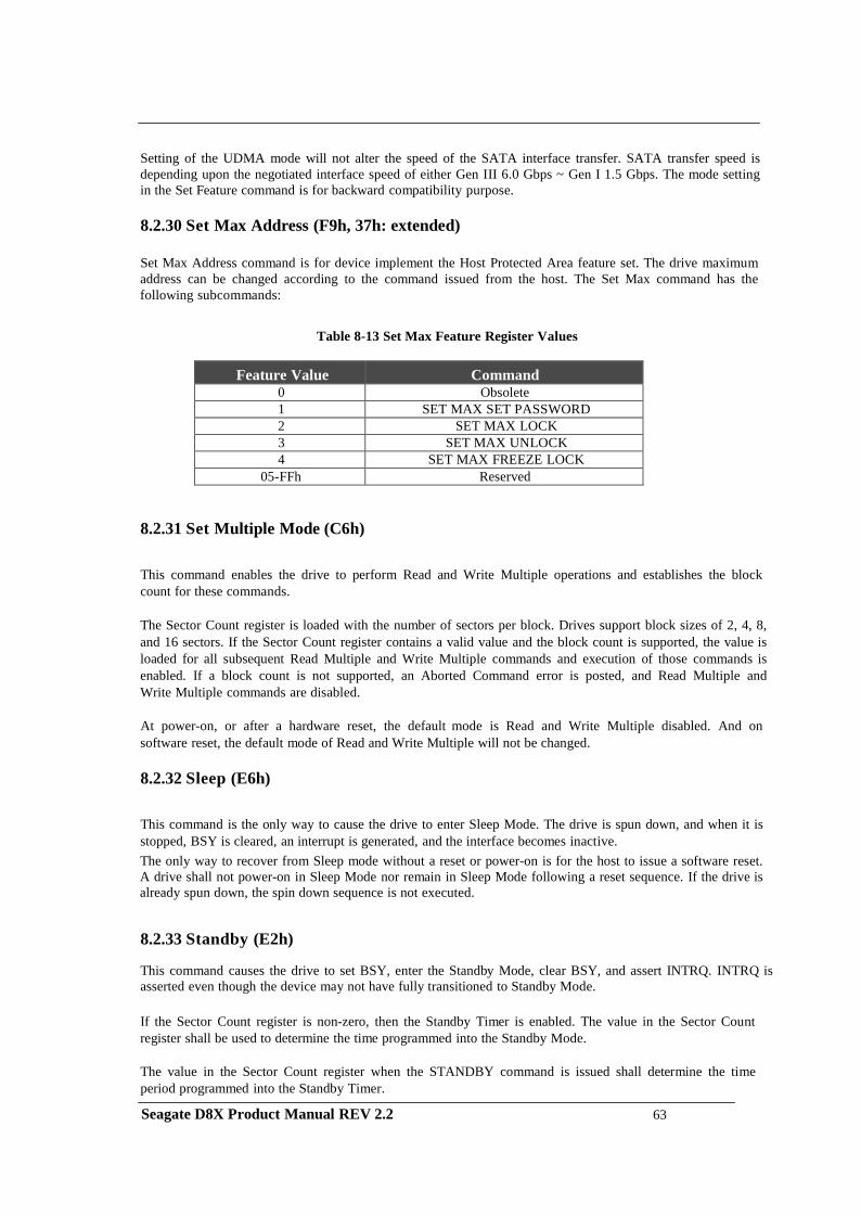
Setting of the UDMA mode will not alter the speed of the SATA interface transfer. SATA transfer speed is depending upon the negotiated interface speed of either Gen III 6.0 Gbps ~ Gen I 1.5 Gbps. The mode setting in the Set Feature command is for backward compatibility purpose.
8.2.30 Set Max Address (F9h, 37h: extended)
Set Max Address command is for device implement the Host Protected Area feature set. The drive maximum address can be changed according to the command issued from the host. The Set Max command has the following subcommands:
Table 8-13 Set Max Feature Register Values
Feature Value Command 0 Obsolete 1 SET MAX SET PASSWORD 2 SET MAX LOCK 3 SET MAX UNLOCK 4 SET MAX FREEZE LOCK
05-FFh Reserved
8.2.31 Set Multiple Mode (C6h)
This command enables the drive to perform Read and Write Multiple operations and establishes the block count for these commands.
The Sector Count register is loaded with the number of sectors per block. Drives support block sizes of 2, 4, 8, and 16 sectors. If the Sector Count register contains a valid value and the block count is supported, the value is loaded for all subsequent Read Multiple and Write Multiple commands and execution of those commands is enabled. If a block count is not supported, an Aborted Command error is posted, and Read Multiple and Write Multiple commands are disabled.
At power-on, or after a hardware reset, the default mode is Read and Write Multiple disabled. And on software reset, the default mode of Read and Write Multiple will not be changed.
8.2.32 Sleep (E6h)
This command is the only way to cause the drive to enter Sleep Mode. The drive is spun down, and when it is stopped, BSY is cleared, an interrupt is generated, and the interface becomes inactive. The only way to recover from Sleep mode without a reset or power-on is for the host to issue a software reset. A drive shall not power-on in Sleep Mode nor remain in Sleep Mode following a reset sequence. If the drive is already spun down, the spin down sequence is not executed.
8.2.33 Standby (E2h)
This command causes the drive to set BSY, enter the Standby Mode, clear BSY, and assert INTRQ. INTRQ is asserted even though the device may not have fully transitioned to Standby Mode. If the Sector Count register is non-zero, then the Standby Timer is enabled. The value in the Sector Count register shall be used to determine the time programmed into the Standby Mode.
The value in the Sector Count register when the STANDBY command is issued shall determine the time period programmed into the Standby Timer.
Seagate D8X Product Manual REV 2.2 63
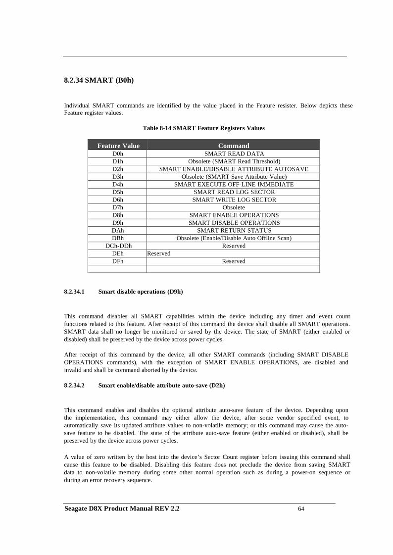
8.2.34 SMART (B0h)
Individual SMART commands are identified by the value placed in the Feature resister. Below depicts these Feature register values.
Table 8-14 SMART Feature Registers Values
Feature Value Command
D0h SMART READ DATA D1h Obsolete (SMART Read Threshold) D2h SMART ENABLE/DISABLE ATTRIBUTE AUTOSAVE D3h Obsolete (SMART Save Attribute Value) D4h SMART EXECUTE OFF-LINE IMMEDIATE D5h SMART READ LOG SECTOR D6h SMART WRITE LOG SECTOR D7h Obsolete D8h SMART ENABLE OPERATIONS D9h SMART DISABLE OPERATIONS DAh SMART RETURN STATUS DBh Obsolete (Enable/Disable Auto Offline Scan)
DCh-DDh Reserved DEh Reserved DFh Reserved
8.2.34.1 Smart disable operations (D9h)
This command disables all SMART capabilities within the device including any timer and event count functions related to this feature. After receipt of this command the device shall disable all SMART operations. SMART data shall no longer be monitored or saved by the device. The state of SMART (either enabled or disabled) shall be preserved by the device across power cycles.
After receipt of this command by the device, all other SMART commands (including SMART DISABLE OPERATIONS commands), with the exception of SMART ENABLE OPERATIONS, are disabled and invalid and shall be command aborted by the device.
8.2.34.2 Smart enable/disable attribute auto-save (D2h)
This command enables and disables the optional attribute auto-save feature of the device. Depending upon the implementation, this command may either allow the device, after some vendor specified event, to automatically save its updated attribute values to non-volatile memory; or this command may cause the auto- save feature to be disabled. The state of the attribute auto-save feature (either enabled or disabled), shall be preserved by the device across power cycles. A value of zero written by the host into the device’s Sector Count register before issuing this command shall cause this feature to be disabled. Disabling this feature does not preclude the device from saving SMART data to non-volatile memory during some other normal operation such as during a power-on sequence or during an error recovery sequence.
Seagate D8X Product Manual REV 2.2 64
A value of F1h written by the host into the device’s Sector Count Register before issuing this command shall cause this feature to be enabled. Any other meaning of this value or any other non-zero value written by the host into this register before issuing this command may differ from device to device.
8.2.34.3 Smart enable operations (D8h)
This command enables all SMART capabilities within the device. Prior to receipt of this command SMART data are neither monitored nor saved by the device. The state of SMART (either enabled or disabled) shall be preserved by the device across power cycles. Once enabled, the receipt of subsequent SMART ENABLE OPERATIONS commands shall not affect any SMART data or functions.
8.2.34.4 Smart execute off-line immediate (D4h)
This command causes the device to immediately initiate the activities that collect SMART data in an off-line mode and then save this data to the device’s non-volatile memory.
During execution of its off-line activities the device shall not set BSY nor clear DRDY.
If the device is in the process of performing its set of off-line data collection activities (as a result of receiving a SMART EXECUTE OFF-LINE IMMEDIATE command from the host), and is interrupted by any new command from the host except a SMART DISABLE OPERATIONS, SMART EXECUTE OFF-LINE IMMEDIATE, or STANDBY IMMEDIATE command, the device shall suspend or abort its off-line data collection activities and service the host within two seconds after receipt of the new command. After servicing the interrupting command from host the device may immediately re-initiate or resume its off-line data collection activities without any additional commands from host
If the device is in the process of performing its off-line data collection activities and is interrupted by a STANDBY IMMEDIATE command from the host, the device shall suspend or abort its off-line data collection activities, and service the host within two seconds after receipt of the command. After receiving a new command that causes the device to exit a power saving mode, the device shall initiate or resume off-line data collection activities without any additional commands from the host unless the device aborted these activities.
If the device is in the process of performing its off-line data collection activities and is interrupted by a SMART DISABLE OPERATIONS command from the host, the device shall suspend or abort its off-line data collection activities and service the host within two seconds after receipt of the command. Upon receipt of the next SMART ENABLE OPERATIONS command the device may, after the next vendor specified event, either re-initiate its off-line data collection activities or resume those activities from where they had been previously suspended.
If the device is in the process of performing its off-line data collection activities and is interrupted by a SMART EXECUTE OFF-LINE IMMEDIATE command from the host, the device shall abort its off-line data collection activities and service the host within two seconds after receipt of the command. The device shall then re-initiate its off-line data collection activities in response to the new EXECUTE OFF-LINE IMMEDIATE command.
Seagate D8X Product Manual REV 2.2 65
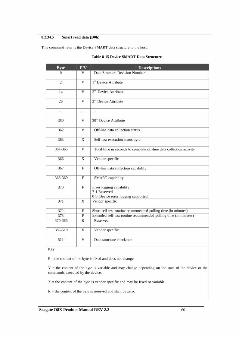
8.2.34.5 Smart read data (D0h)
This command returns the Device SMART data structure to the host.
Table 8-15 Device SMART Data Structure
Byte F/V Descriptions
0 V Data Structure Revision Number
2 V 1st Device Attribute
14 V 2nd Device Attribute
26 V 3rd Device Attribute
… … …
350 V 30th Device Attribute
362 V Off-line data collection status
363 X Self-test execution status byte
364-365 V Total time in seconds to complete off-line data collection activity
366 X Vendor specific
367 F Off-line data collection capability
368-369 F SMART capability
370 F Error logging capability 7-1 Reserved 0 1=Device error logging supported
371 X Vendor specific
372 F Short self-test routine recommended polling time (in minutes) 373 F Extended self-test routine recommended polling time (in minutes)
370-385 R Reserved
386-510 X Vendor specific
511 V Data structure checksum
Key: F = the content of the byte is fixed and does not change.
V = the content of the byte is variable and may change depending on the state of the device or the commands executed by the device.
X = the content of the byte is vendor specific and may be fixed or variable.
R = the content of the byte is reserved and shall be zero.
Seagate D8X Product Manual REV 2.2 66
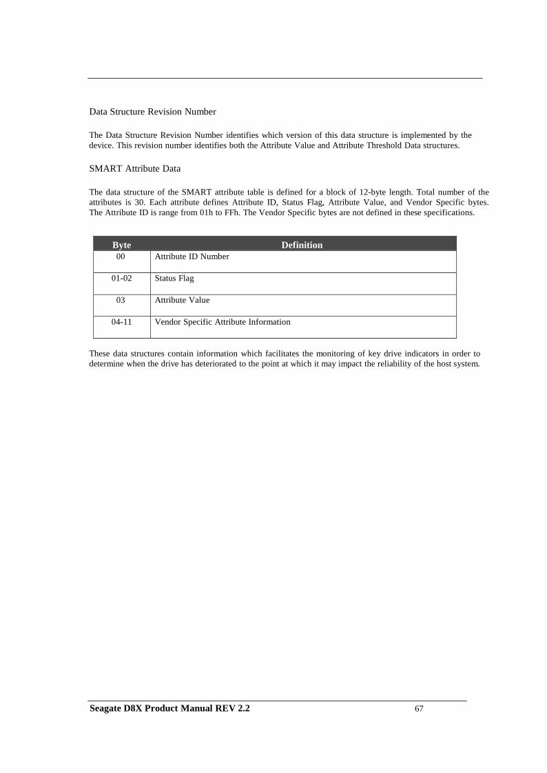
Data Structure Revision Number
The Data Structure Revision Number identifies which version of this data structure is implemented by the device. This revision number identifies both the Attribute Value and Attribute Threshold Data structures.
SMART Attribute Data
The data structure of the SMART attribute table is defined for a block of 12-byte length. Total number of the attributes is 30. Each attribute defines Attribute ID, Status Flag, Attribute Value, and Vendor Specific bytes. The Attribute ID is range from 01h to FFh. The Vendor Specific bytes are not defined in these specifications.
Byte Definition 00 Attribute ID Number
01-02 Status Flag
03 Attribute Value
04-11 Vendor Specific Attribute Information
These data structures contain information which facilitates the monitoring of key drive indicators in order to determine when the drive has deteriorated to the point at which it may impact the reliability of the host system.
Seagate D8X Product Manual REV 2.2 67
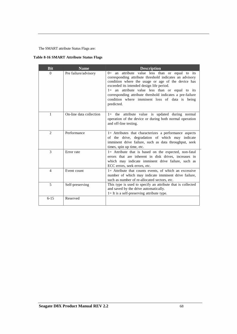
The SMART attribute Status Flags are:
Table 8-16 SMART Attribute Status Flags
Bit Name Description 0 Pre failure/advisory 0= an attribute value less than or equal to its
corresponding attribute threshold indicates an advisory condition where the usage or age of the device has exceeded its intended design life period. 1= an attribute value less than or equal to its corresponding attribute threshold indicates a pre-failure condition where imminent loss of data is being predicted.
1 On-line data collection 1= the attribute value is updated during normal operation of the device or during both normal operation and off-line testing.
2 Performance 1= Attributes that characterizes a performance aspects of the drive, degradation of which may indicate imminent drive failure, such as data throughput, seek times, spin up time, etc.
3 Error rate 1= Attribute that is based on the expected, non-fatal errors that are inherent in disk drives, increases in which may indicate imminent drive failure, such as ECC errors, seek errors, etc.
4 Event count 1= Attribute that counts events, of which an excessive number of which may indicate imminent drive failure, such as number of re-allocated sectors, etc.
5 Self-preserving This type is used to specify an attribute that is collected and saved by the drive automatically. 1= It is a self-preserving attribute type.
6-15 Reserved
Seagate D8X Product Manual REV 2.2 68
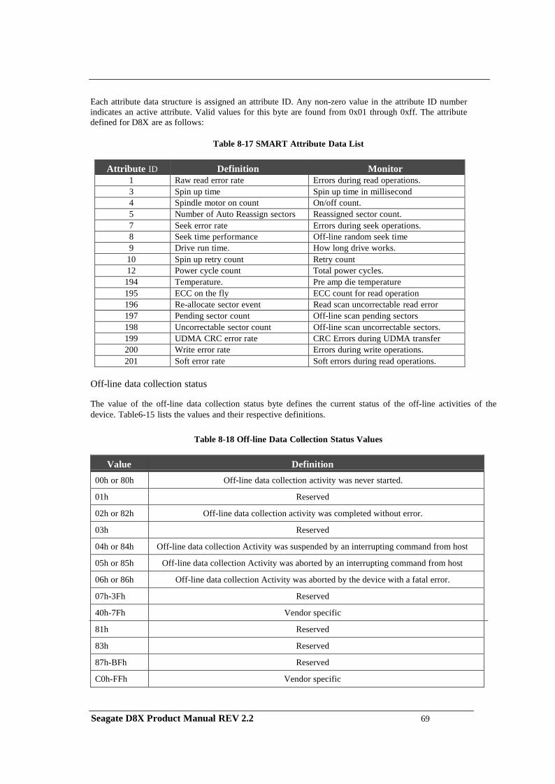
Each attribute data structure is assigned an attribute ID. Any non-zero value in the attribute ID number indicates an active attribute. Valid values for this byte are found from 0x01 through 0xff. The attribute defined for D8X are as follows:
Table 8-17 SMART Attribute Data List
Attribute ID Definition Monitor
1 Raw read error rate Errors during read operations. 3 Spin up time Spin up time in millisecond 4 Spindle motor on count On/off count. 5 Number of Auto Reassign sectors Reassigned sector count. 7 Seek error rate Errors during seek operations. 8 Seek time performance Off-line random seek time 9 Drive run time. How long drive works.
10 Spin up retry count Retry count 12 Power cycle count Total power cycles.
194 Temperature. Pre amp die temperature 195 ECC on the fly ECC count for read operation 196 Re-allocate sector event Read scan uncorrectable read error 197 Pending sector count Off-line scan pending sectors 198 Uncorrectable sector count Off-line scan uncorrectable sectors. 199 UDMA CRC error rate CRC Errors during UDMA transfer 200 Write error rate Errors during write operations. 201 Soft error rate Soft errors during read operations.
Off-line data collection status
The value of the off-line data collection status byte defines the current status of the off-line activities of the device. Table6-15 lists the values and their respective definitions.
Table 8-18 Off-line Data Collection Status Values
Value Definition
00h or 80h Off-line data collection activity was never started.
01h Reserved
02h or 82h Off-line data collection activity was completed without error.
03h Reserved
04h or 84h Off-line data collection Activity was suspended by an interrupting command from host
05h or 85h Off-line data collection Activity was aborted by an interrupting command from host
06h or 86h Off-line data collection Activity was aborted by the device with a fatal error.
07h-3Fh Reserved
40h-7Fh Vendor specific
81h Reserved 83h Reserved 87h-BFh Reserved C0h-FFh Vendor specific
Seagate D8X Product Manual REV 2.2 69
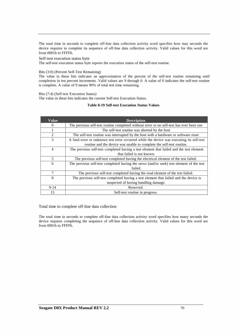
The total time in seconds to complete off-line data collection activity word specifies how may seconds the device requires to complete its sequence of off-line data collection activity. Valid values for this word are from 0001h to FFFFh. Self-test execution status byte The self-test execution status byte reports the execution status of the self-test routine.
Bits (3:0) (Percent Self-Test Remaining) The value in these bits indicates an approximation of the percent of the self-test routine remaining until completion in ten percent increments. Valid values are 9 through 0. A value of 0 indicates the self-test routine is complete. A value of 9 means 90% of total test time remaining. Bits (7:4) (Self-test Execution Status) The value in these bits indicates the current Self-test Execution Status.
Table 8-19 Self-test Execution Status Values
Value Description 0 The previous self-test routine completed without error or no self-test has ever been run 1 The self-test routine was aborted by the host 2 The self-test routine was interrupted by the host with a hardware or software reset 3 A fatal error or unknown test error occurred while the device was executing its self-test
routine and the device was unable to complete the self-test routine. 4 The previous self-test completed having a test element that failed and the test element
that failed is not known. 5 The previous self-test completed having the electrical element of the test failed. 6 The previous self-test completed having the servo (and/or seek) test element of the test
failed. 7 The previous self-test completed having the read element of the test failed. 8 The previous self-test completed having a test element that failed and the device is
suspected of having handling damage. 9-14 Reserved. 15 Self-test routine in progress.
Total time to complete off-line data collection
The total time in seconds to complete off-line data collection activity word specifies how many seconds the device requires completing the sequence of off-line data collection activity. Valid values for this word are from 0001h to FFFFh.
Seagate D8X Product Manual REV 2.2 70
Off-line data collection capability
The following describes the definition for the off-line data collection capability bits. If the value of all of these bits is equal to zero, then this device implements no off-line data collection.
Bit 0 (EXECUTE OFF-LINE IMMEDIATE implemented bit) – If the value of this bit equals one, then the SMART EXECUTE OFF-LINE IMMEDIATE command is implemented by this device. If the value of this bit equals zero, then the SMART EXECUTE OFF-LINE IMMEDIATE command is not implemented by this device.
Bit 1 (vendor specific)
Bit 2 (abort/restart off-line by host bit) – If the value of this bit equals one, then the device shall abort all
off-line data collection activity initiated by an SMART EXECUTE OFF-LINE IMMEDIATE command upon receipt of a new command. Off-line data collection activity must be restarted by a new SMART EXECUTE OFF-LINE IMMEDIATE command from the host. If the value of this bit equals zero, the device shall suspend off-line data collection activity after an interrupting command and resume off-line data collection activity after some vendor-specified event.
Bit 3 (off-line read scanning implemented bit) - If this bit is cleared to zero, the device does not support
off-line read scanning. If this bit is set to one, the device supports off-line read scanning
Bit 4 (self-test implemented bit) – If this bit is cleared to zero, the device does not implement the Short and Extended self-test routines. If this bit is set to one, the device implements the Short and Extended self-test routines.
Bit 7-5 (reserved). SMART capability
The following describes the definition for the SMART capability bits. If the value of all of these bits is equal to zero, then this device does not implement automatic saving of SMART data.
Bit 0 (power mode SMART data saving capability bit) – If the value of this bit equals one, the device shall save its SMART data prior to going into a power saving mode (Idle, Standby, or Sleep) or immediately upon return to Active or Idle mode from a Standby mode. If the value of this bit equals zero, the device shall not save its SMART date prior to going into a power saving mode (Idle, Standby, or Sleep) or immediately upon return to Active or Idle mode from a Standby mode.
Bit 1 (SMART data auto-save after event capability bit) – The value of this bit shall be equal to one for
devices complying with this standard.
Bits 2-15 (reserved).
Self-test routine recommended polling time
The self-test routine recommended polling time shall be equal to the number of minutes that is the minimum recommended time before which the host should first poll for test completion status. Actual test time could be several times this value. Polling before this time could extend the self-test execution time or abort the test depending on the state of bit 2 of the off-line data capability bits.
The data structure checksum is the two’s compliment of the result of a simple eight-bit addition of the first 511 bytes in the data structure.
Seagate D8X Product Manual REV 2.2 71
8.2.34.6 SMART read log sector (D5h)
This command returns the indicated log sectors to the host.
8.2.34.7 SMART return status (DAh)
This command is used to communicate the reliability status of the device to the host at the host’s request. If a threshold exceeded condition is not detected by the device, the device shall set the Cylinder Low register to 4Fh and the Cylinder High register to C2h. If the device detects a threshold-exceeded condition, the device shall set Cylinder Low register to F4h and Cylinder High register to 2Ch
8.2.34.8 SMART write log sector (D6h)
This command writes number of 512-byte data sectors to the indicated log sector.
8.2.35 Standby (E2h)
This command causes the drive to enter Standby Mode. See 6.6.3 for the protocol. The drive may return the interrupt before the transition to Standby Mode is completed.
If the drive is already spun down, the spin down sequence is not executed.
8.2.36 Standby Immediate (E0h)
This command causes the drive to enter Standby Mode. See 6.6.3 for the protocol. The drive may return the interrupt before the transition to Standby Mode is completed.
If the drive is already spun down, the spin down sequence is not executed.
8.2.37 Write Buffer (E8h)
This command enables the host to overwrite the contents of the drive's sector buffer with any data pattern desired. See 6.6.2 for the protocol.
The Read Buffer and Write Buffer commands is synchronized within the drive so that sequential Write Buffer and Read Buffer commands access the same 512 bytes within the buffer.
8.2.38 Write DMA (CAh, 35h: extended)
This command executes in a similar manner to Write Sector(s) except the drive issues only one interrupt per command to indicate that data transfer has terminated and status is available.
Any error encountered during Write DMA execution results in the termination of data transfer. The drive issues an interrupt to indicate that data transfer has terminated and the status is available in the Error register. The error posting is the same as that for the Write Sector(s) command.
Seagate D8X Product Manual REV 2.2 72
8.2.39 Write FPDMA Queued (61h)
This command is implemented according to the Serial ATA II: Extension to Serial ATA 1.0a, Revision 1.2 specification. The purpose of this command is for the host to issue a Native Command Queue (NCQ) write commands. This command allows device to reorder the command issued in a sequence of the queue. The command is returned based on the device’s determine of the location sequence.
The D8X drive implemented a queue depth of 32. This will allow host to issue up to 32 NCQ commands (combined read and write commands).
If the drive enters NCQ mode and a non-queue command is received, the drive will respond with error to inform host a queue command been overlapped with non-queue. If a queue tag is not finished and another same tag command is received, the drive will response with error to inform host a duplicated tag is received.
Error information is reported according to the SATA III specification. A read Log Extended command with log page 10 h is required to retrieve the error information 8.2.40 Write Long (32h)
This command is obsolete in the ATA7 specification. The supporting of this command is for backward compatibility purpose. The use of this command is beyond the ATA standard and not recommended by the manufacturer.
This command is similar to the Write Sectors command, except that it writes the data and the ECC bytes directly from the sector buffer; the drive does not generate the ECC bytes itself. Only single sector Write Long operations are supported. The transfer of the ECC bytes shall be 8 bits wide and 4 or device native ECC bytes length.
8.2.41 Write Multiple Command (C5h, 39h: extended)
This command is similar to the Write Sectors command. Interrupts are not presented on each sector but on the transfer of a block which contains the number of sectors defined by Set Multiple.
Command execution is identical to the Write Sectors operation, except that the numbers of sectors defined by the Set Multiple command are transferred without intervening interrupts. DRQ qualification of the transfer is required only at the start of the data block, not on each sector.
The block count of sectors to be transferred without intervening interrupts is programmed by the Set Multiple Mode command, which shall be executed prior to the Read Multiple command.
When the Write Multiple command is issued, the Sector Count register contains the number of sectors (not the number of blocks or the block count) requested.
Seagate D8X Product Manual REV 2.2 73
If the number of requested sectors is not evenly divisible by the block count, as many full blocks as possible are transferred, followed by a final, partial block transfer. The partial block transfer is for n sectors, where
n = Remainder (Sector Count / Block Count) If the Write Multiple command is attempted before the Set Multiple Mode command has been executed, or when Write Multiple commands are disabled, the Write Multiple operation is rejected with an aborted command error.
Disk errors encountered during execution of Write Multiple commands are posted after the attempted disk write of the block. Interrupts are generated when DRQ is set at the beginning of each block or partial block.
The contents of the Command Block registers, following the transfer of a data block which had a sector in error, are undefined. The host should retry the transfer as individual requests to obtain valid error information.
8.2.42 Write Sector(s) (30h, 34h: extended)
This command writes from 1 to 256 sectors, as specified in the Sector Count register (a sector count of zero requests 256 sectors), beginning at the specified sector. Refer to Section 6.7 for the DRQ, IRQ and BSY protocol on data transfers.
If the drive is not already on the desired track, an implied seek is performed. Once at the desired track, the drive searches for the appropriate ID field.
If retries are disabled and two index pulses have occurred without error-free reading of the requested ID, an ID Not Found error is posted. If retries are enabled, up to a predefined number of attempts may be made to read the requested ID before posting an error.
If the ID is read correctly, the data loaded in the buffer is written to the data field of the sector, followed by the ECC bytes. Upon command completion, the Command Block registers contain the cylinder, head, and sector number of the last sector written in CHS mode or the logical block address in LBA mode.
If an error occurs during a write of more than one sector, writing terminates at the sector where the error occurs. The Command Block registers contain the cylinder, head, and sector number of the sector where the error occurred in CHS mode or the logical block address in LBA mode. The host may then read the command block to determine what error has occurred and on which sector it occurred.
Seagate D8X Product Manual REV 2.2 74
CHAPTER 9 MAINTENANCE
9.1 General Information
Seagate D8X hard disk drive achieves high reliability through their mechanical design and extensive use of microelectronics. Their design allows fast, easy sub-assembly replacement without adjustments, greatly reducing the amount of downtime required for unscheduled repairs.
9.2 Maintenance Precautions
When servicing a drive, the service technician should observe the following precautions to avoid damage to the drive or personal injury.
(1) Do not attempt to open the sealed compartment of the D8X hard disk drive, as this will void the warranty and contaminate the media.
(2) Do not lift the D8X hard disk drive by the PCB.
(3) Please handle HDD by side surfaces Please see the Fig. 9-1
(4) Avoid static discharge when handling the D8X hard disk drive.
(5) Do not touch cover and the components on the PCB. Please see the Fig. 9-2
(6) Do not stack the HDDs in column
Please see the Fig. 9-3
(7) Avoid harsh shocks or vibration to the drive at all times. Please see the Fig. 9-4
(8) Observe the environmental limits specified for this product, as listed in section 3.6.
(9) If it becomes necessary to move your computer system, turn off the power to automatically
park the heads. Parking the heads moves the heads to a safe, non-data landing zone and locks the heads in place. This helps prevent the media and the heads from accidental damage due to vibration, moving or shipping. Do not move the drive for 20 seconds after removing DC power to ensure that the actuator is completely locked.
Back up your data regularly. Seagate assumes no responsibility for loss of data. For information about back- up and restore procedures, consult your DOS manual. There are also a number of utility programs available that you can use to back up your data.
Seagate D8X Product Manual REV 2.2 75
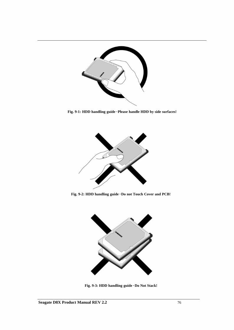
Fig. 9-1: HDD handling guide - Please handle HDD by side surfaces!
Fig. 9-2: HDD handling guide - Do not Touch Cover and PCB!
Fig. 9-3: HDD handling guide - Do Not Stack!
Seagate D8X Product Manual REV 2.2 76
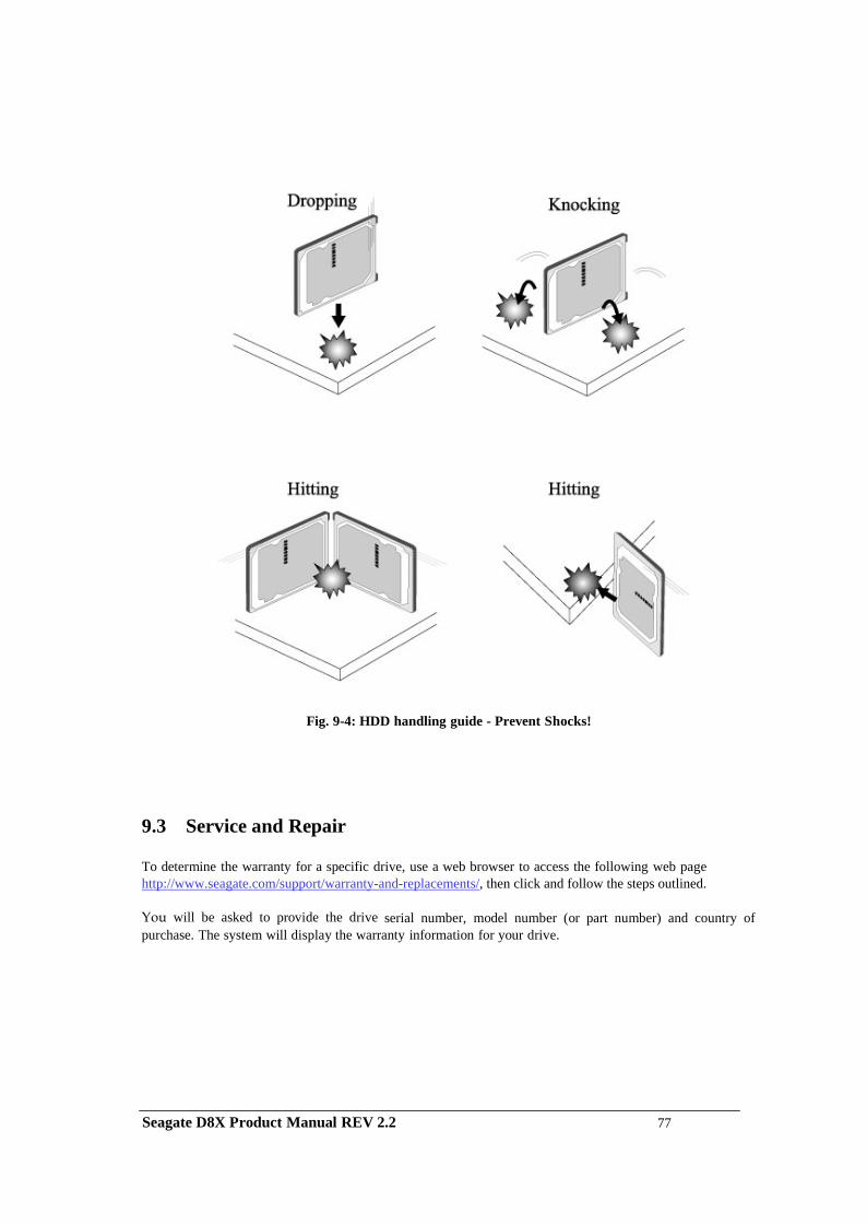
Fig. 9-4: HDD handling guide - Prevent Shocks!
9.3 Service and Repair
To determine the warranty for a specific drive, use a web browser to access the following web page http://www.seagate.com/support/warranty-and-replacements/, then click and follow the steps outlined. You will be asked to provide the drive serial number, model number (or part number) and country of purchase. The system will display the warranty information for your drive.
Seagate D8X Product Manual REV 2.2 77


![WELCOME []...eligible for participation in the Seagate Insider program. Other exclusions may apply. Other exclusions may apply. Seagate Technology LLC, 47488 Kato Road, Fremont, CA](https://img.pdfslide.net/doc/110x75/600c3aeb428532354229e596/welcome-eligible-for-participation-in-the-seagate-insider-program-other.jpg)