Embed Size (px)
Citation preview
Surgical Technique Manual
Note: The surgical procedures should be performed under the guidance of qualified skilled
orthopedic surgeons, and this surgical technique manual is provided for information only.
Orthopedic Bone Nail System Universal Tibial Nail
Indication:
-Tibial fracture
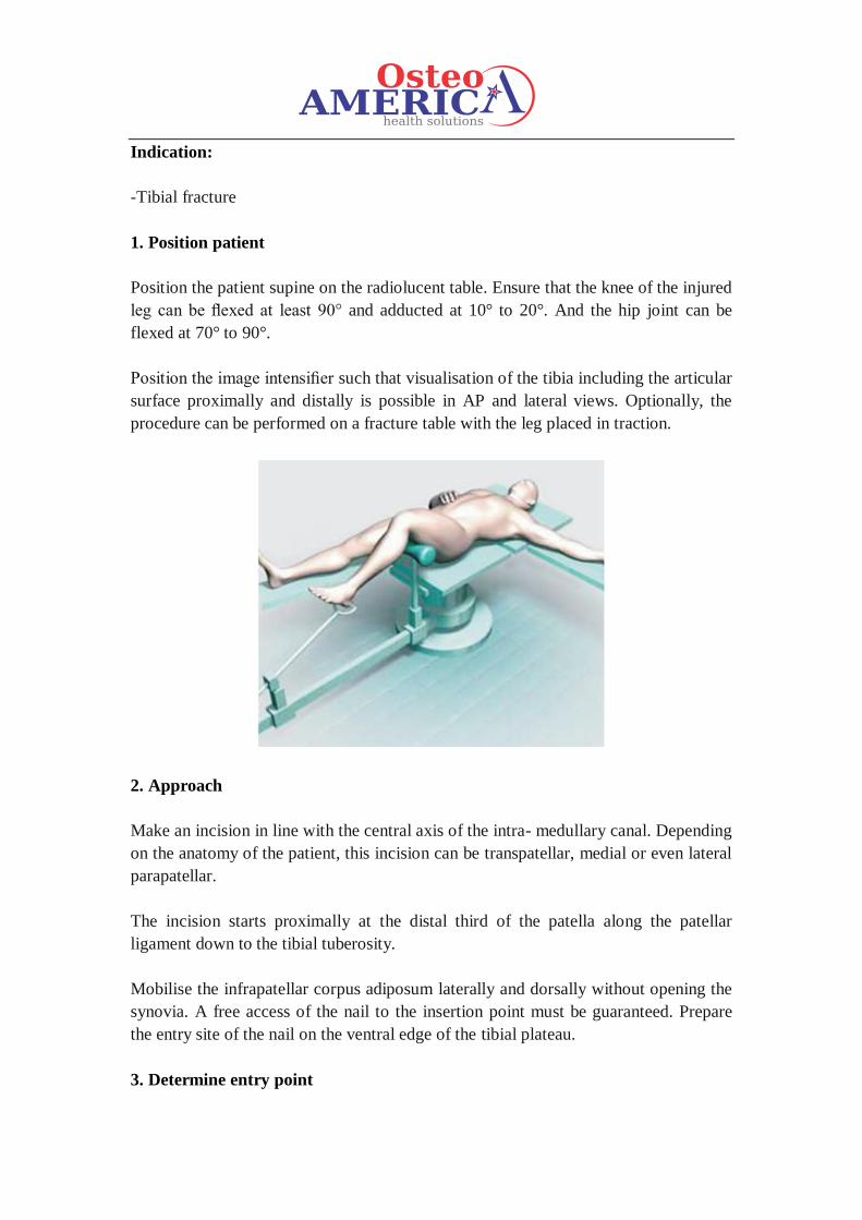
1. Position patient
Position the patient supine on the radiolucent table. Ensure that the knee of the injured
leg can be flexed at least 90° and adducted at 10° to 20°. And the hip joint can be
flexed at 70° to 90°.
Position the image intensifier such that visualisation of the tibia including the articular
surface proximally and distally is possible in AP and lateral views. Optionally, the
procedure can be performed on a fracture table with the leg placed in traction.
2. Approach
Make an incision in line with the central axis of the intra- medullary canal. Depending
on the anatomy of the patient, this incision can be transpatellar, medial or even lateral
parapatellar.
The incision starts proximally at the distal third of the patella along the patellar
ligament down to the tibial tuberosity.
Mobilise the infrapatellar corpus adiposum laterally and dorsally without opening the
synovia. A free access of the nail to the insertion point must be guaranteed. Prepare
the entry site of the nail on the ventral edge of the tibial plateau.
3. Determine entry point
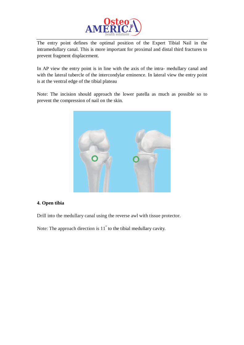
The entry point defines the optimal position of the Expert Tibial Nail in the
intramedullary canal. This is more important for proximal and distal third fractures to
prevent fragment displacement.
In AP view the entry point is in line with the axis of the intra- medullary canal and
with the lateral tubercle of the intercondylar eminence. In lateral view the entry point
is at the ventral edge of the tibial plateau
Note: The incision should approach the lower patella as much as possible so to
prevent the compression of nail on the skin.
4. Open tibia
Drill into the medullary canal using the reverse awl with tissue protector.
Note: The approach direction is 11° to the tibial medullary cavity.
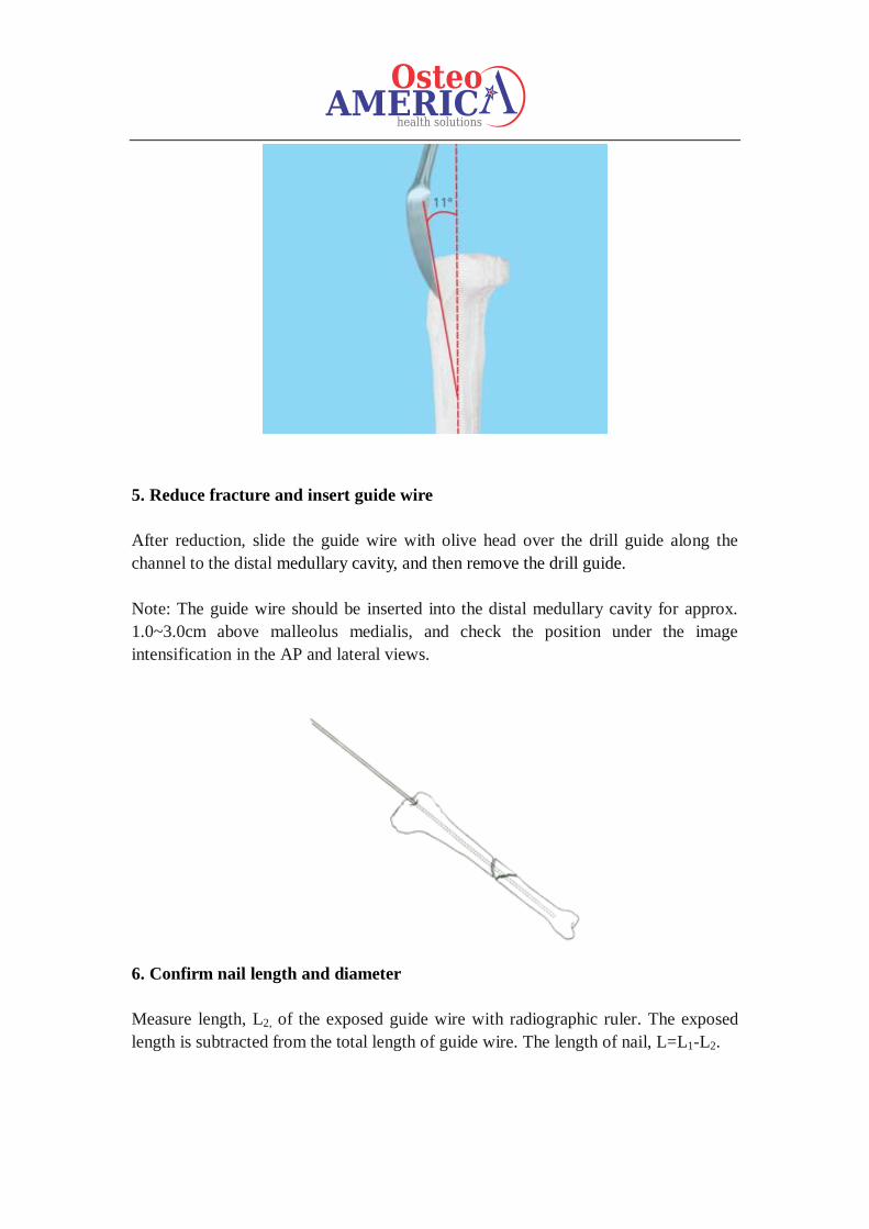
5. Reduce fracture and insert guide wire
After reduction, slide the guide wire with olive head over the drill guide along the
channel to the distal medullary cavity, and then remove the drill guide.
Note: The guide wire should be inserted into the distal medullary cavity for approx.
1.0~3.0cm above malleolus medialis, and check the position under the image
intensification in the AP and lateral views.
6. Confirm nail length and diameter
Measure length, L2, of the exposed guide wire with radiographic ruler. The exposed
length is subtracted from the total length of guide wire. The length of nail, L=L1-L2.
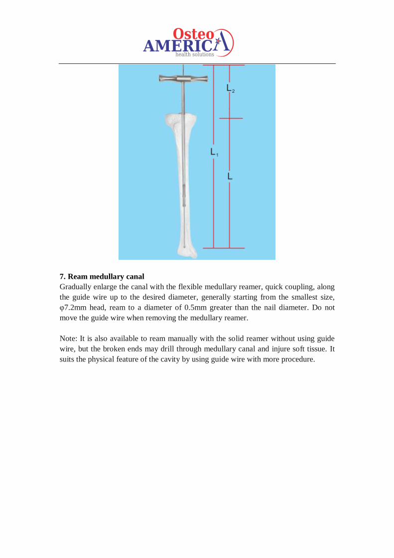
7. Ream medullary canal
Gradually enlarge the canal with the flexible medullary reamer, quick coupling, along
the guide wire up to the desired diameter, generally starting from the smallest size,
φ7.2mm head, ream to a diameter of 0.5mm greater than the nail diameter. Do not
move the guide wire when removing the medullary reamer.
Note: It is also available to ream manually with the solid reamer without using guide
wire, but the broken ends may drill through medullary canal and injure soft tissue. It
suits the physical feature of the cavity by using guide wire with more procedure.
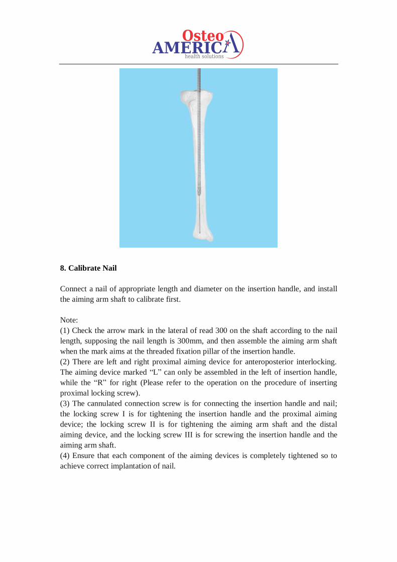
8. Calibrate Nail
Connect a nail of appropriate length and diameter on the insertion handle, and install
the aiming arm shaft to calibrate first.
Note:
(1) Check the arrow mark in the lateral of read 300 on the shaft according to the nail
length, supposing the nail length is 300mm, and then assemble the aiming arm shaft
when the mark aims at the threaded fixation pillar of the insertion handle.
(2) There are left and right proximal aiming device for anteroposterior interlocking.
The aiming device marked “L” can only be assembled in the left of insertion handle,
while the “R” for right (Please refer to the operation on the procedure of inserting
proximal locking screw).
(3) The cannulated connection screw is for connecting the insertion handle and nail;
the locking screw I is for tightening the insertion handle and the proximal aiming
device; the locking screw II is for tightening the aiming arm shaft and the distal
aiming device, and the locking screw III is for screwing the insertion handle and the
aiming arm shaft.
(4) Ensure that each component of the aiming devices is completely tightened so to
achieve correct implantation of nail.
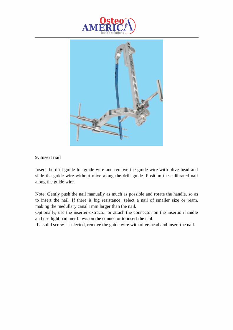
9. Insert nail
Insert the drill guide for guide wire and remove the guide wire with olive head and
slide the guide wire without olive along the drill guide. Position the calibrated nail
along the guide wire.
Note: Gently push the nail manually as much as possible and rotate the handle, so as
to insert the nail. If there is big resistance, select a nail of smaller size or ream,
making the medullary canal 1mm larger than the nail.
Optionally, use the inserter-extractor or attach the connector on the insertion handle
and use light hammer blows on the connector to insert the nail.
If a solid screw is selected, remove the guide wire with olive head and insert the nail.
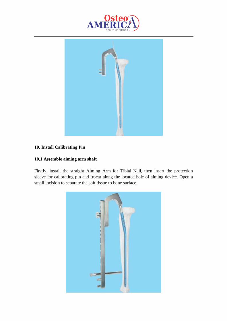
10. Install Calibrating Pin
10.1 Assemble aiming arm shaft
Firstly, install the straight Aiming Arm for Tibial Nail, then insert the protection
sleeve for calibrating pin and trocar along the located hole of aiming device. Open a
small incision to separate the soft tissue to bone surface.
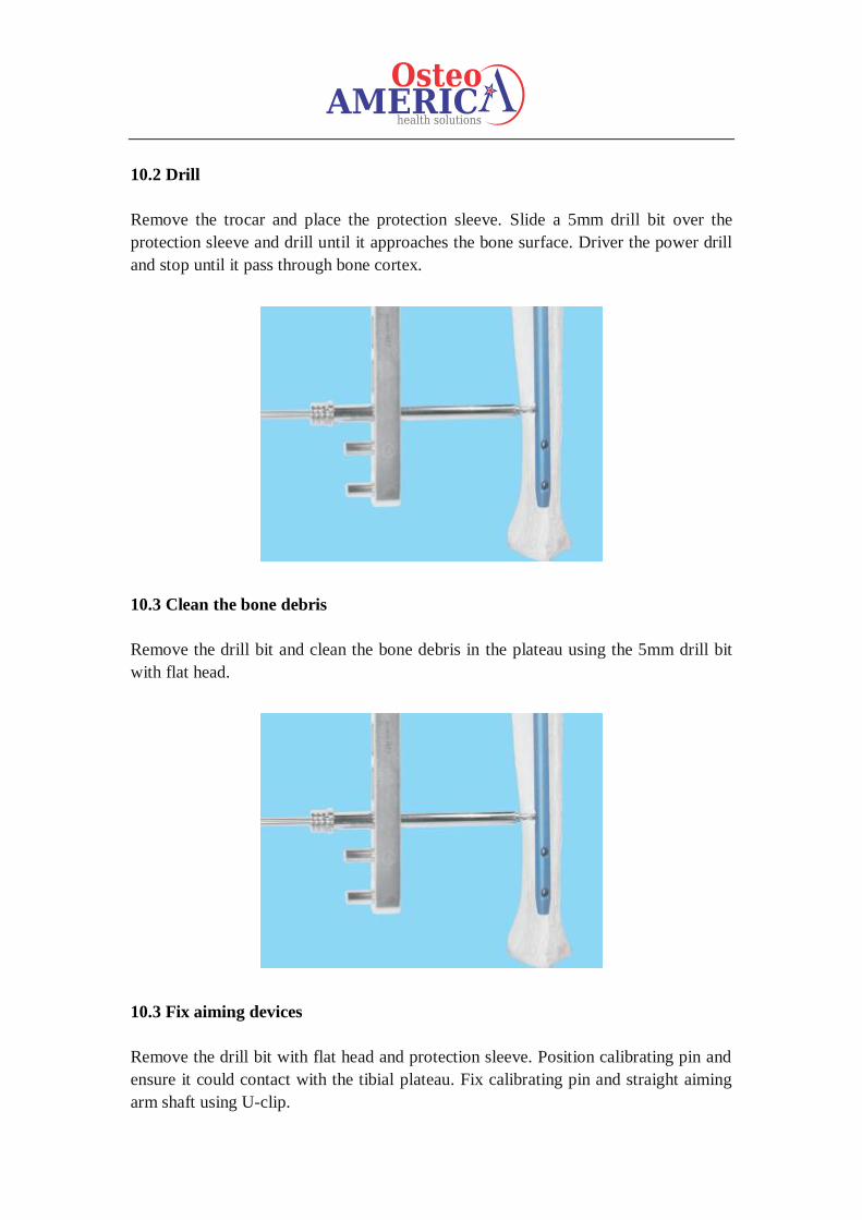
10.2 Drill
Remove the trocar and place the protection sleeve. Slide a 5mm drill bit over the
protection sleeve and drill until it approaches the bone surface. Driver the power drill
and stop until it pass through bone cortex.
10.3 Clean the bone debris
Remove the drill bit and clean the bone debris in the plateau using the 5mm drill bit
with flat head.
10.3 Fix aiming devices
Remove the drill bit with flat head and protection sleeve. Position calibrating pin and
ensure it could contact with the tibial plateau. Fix calibrating pin and straight aiming
arm shaft using U-clip.
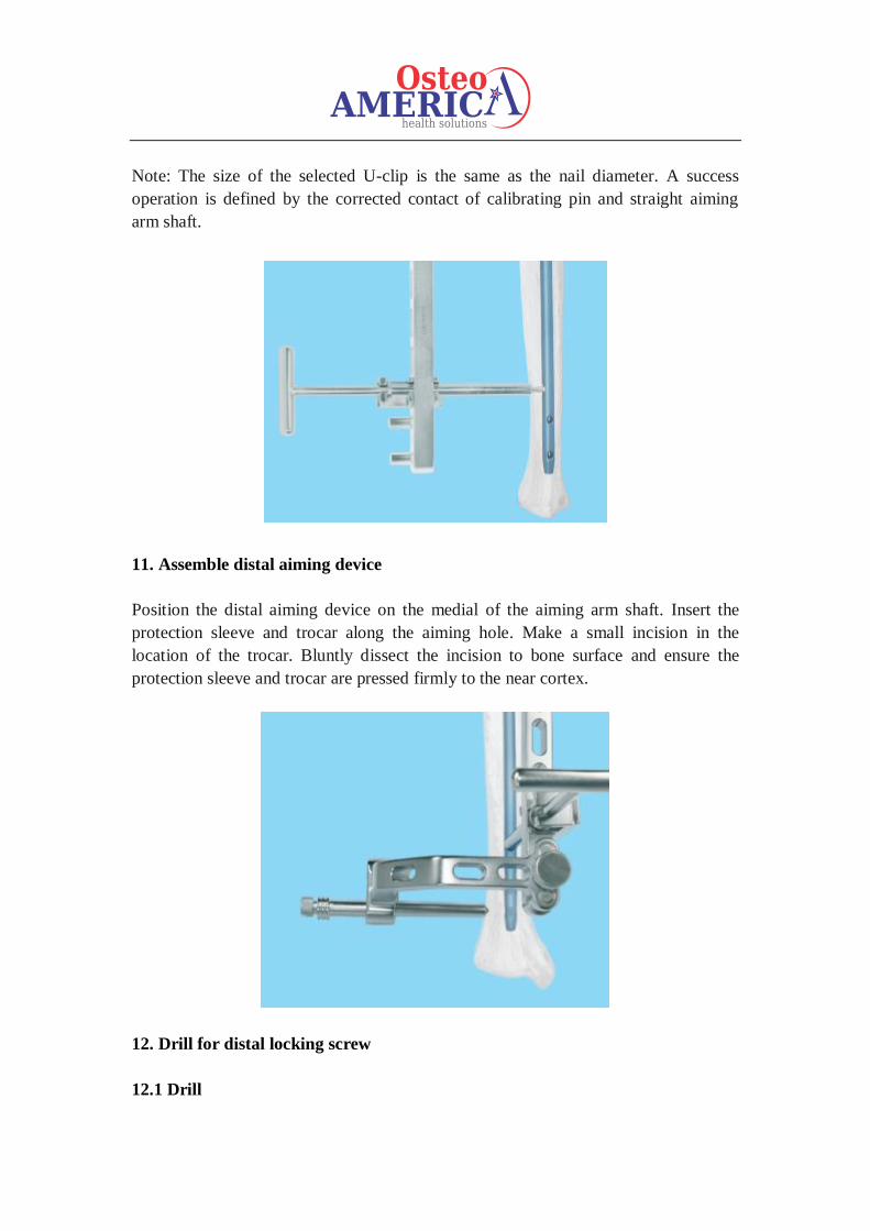
Note: The size of the selected U-clip is the same as the nail diameter. A success
operation is defined by the corrected contact of calibrating pin and straight aiming
arm shaft.
11. Assemble distal aiming device
Position the distal aiming device on the medial of the aiming arm shaft. Insert the
protection sleeve and trocar along the aiming hole. Make a small incision in the
location of the trocar. Bluntly dissect the incision to bone surface and ensure the
protection sleeve and trocar are pressed firmly to the near cortex.
12. Drill for distal locking screw
12.1 Drill
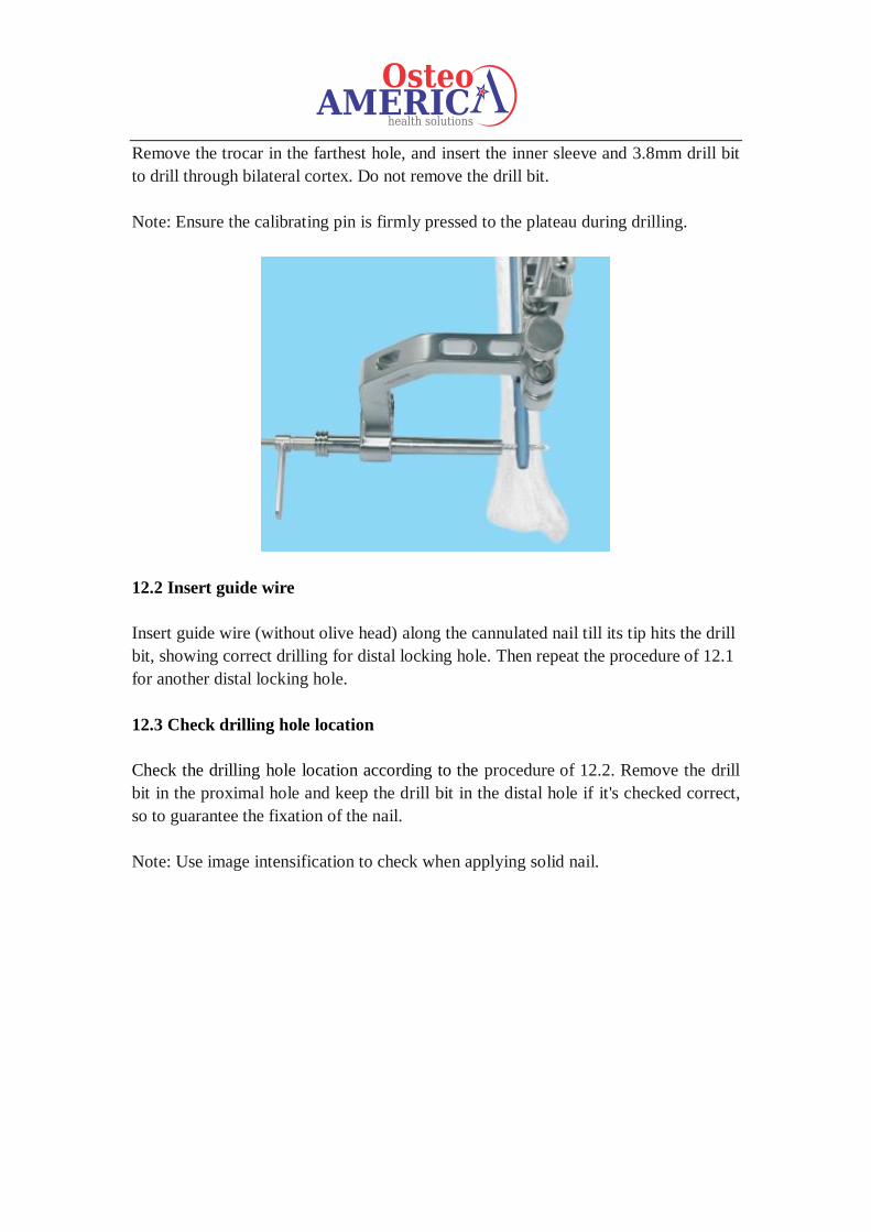
Remove the trocar in the farthest hole, and insert the inner sleeve and 3.8mm drill bit
to drill through bilateral cortex. Do not remove the drill bit.
Note: Ensure the calibrating pin is firmly pressed to the plateau during drilling.
12.2 Insert guide wire
Insert guide wire (without olive head) along the cannulated nail till its tip hits the drill
bit, showing correct drilling for distal locking hole. Then repeat the procedure of 12.1
for another distal locking hole.
12.3 Check drilling hole location
Check the drilling hole location according to the procedure of 12.2. Remove the drill
bit in the proximal hole and keep the drill bit in the distal hole if it's checked correct,
so to guarantee the fixation of the nail.
Note: Use image intensification to check when applying solid nail.
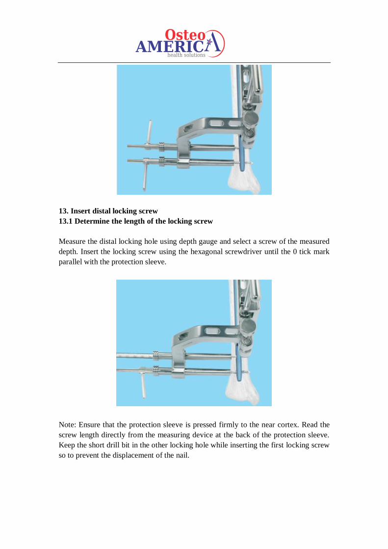
13. Insert distal locking screw
13.1 Determine the length of the locking screw
Measure the distal locking hole using depth gauge and select a screw of the measured
depth. Insert the locking screw using the hexagonal screwdriver until the 0 tick mark
parallel with the protection sleeve.
Note: Ensure that the protection sleeve is pressed firmly to the near cortex. Read the
screw length directly from the measuring device at the back of the protection sleeve.
Keep the short drill bit in the other locking hole while inserting the first locking screw
so to prevent the displacement of the nail.
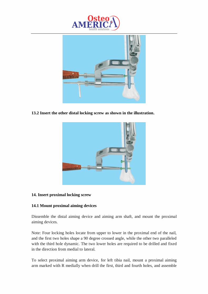
13.2 Insert the other distal locking screw as shown in the illustration.
14. Insert proximal locking screw
14.1 Mount proximal aiming devices
Dissemble the distal aiming device and aiming arm shaft, and mount the proximal
aiming devices.
Note: Four locking holes locate from upper to lower in the proximal end of the nail,
and the first two holes shape a 90 degree crossed angle, while the other two paralleled
with the third hole dynamic. The two lower holes are required to be drilled and fixed
in the direction from medial to lateral.
To select proximal aiming arm device, for left tibia nail, mount a proximal aiming
arm marked with R medially when drill the first, third and fourth holes, and assemble
the one with L mark laterally when drill the second hole. For right tibia nail, fix the
proximal aiming arm with L mark medially during drilling the second, third and
fourth holes, and install the one with R mark on the laterally for drilling the first hole.
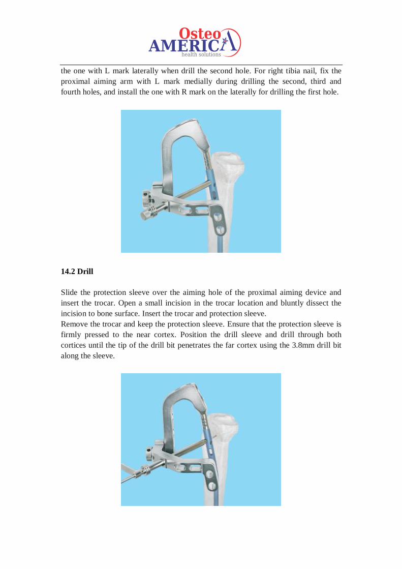
14.2 Drill
Slide the protection sleeve over the aiming hole of the proximal aiming device and
insert the trocar. Open a small incision in the trocar location and bluntly dissect the
incision to bone surface. Insert the trocar and protection sleeve.
Remove the trocar and keep the protection sleeve. Ensure that the protection sleeve is
firmly pressed to the near cortex. Position the drill sleeve and drill through both
cortices until the tip of the drill bit penetrates the far cortex using the 3.8mm drill bit
along the sleeve.
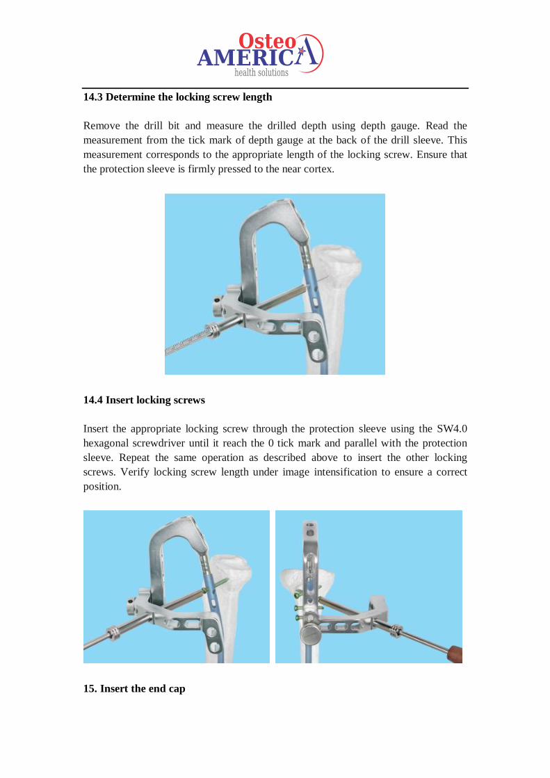
14.3 Determine the locking screw length
Remove the drill bit and measure the drilled depth using depth gauge. Read the
measurement from the tick mark of depth gauge at the back of the drill sleeve. This
measurement corresponds to the appropriate length of the locking screw. Ensure that
the protection sleeve is firmly pressed to the near cortex.
14.4 Insert locking screws
Insert the appropriate locking screw through the protection sleeve using the SW4.0
hexagonal screwdriver until it reach the 0 tick mark and parallel with the protection
sleeve. Repeat the same operation as described above to insert the other locking
screws. Verify locking screw length under image intensification to ensure a correct
position.
15. Insert the end cap
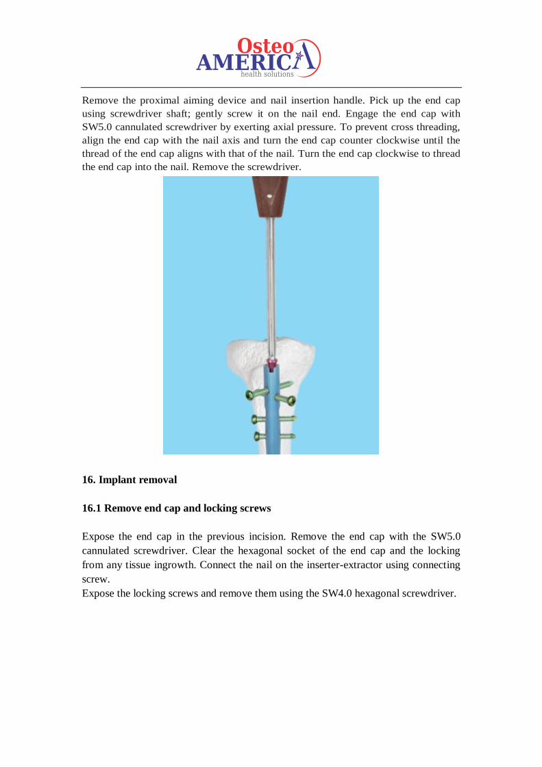
Remove the proximal aiming device and nail insertion handle. Pick up the end cap
using screwdriver shaft; gently screw it on the nail end. Engage the end cap with
SW5.0 cannulated screwdriver by exerting axial pressure. To prevent cross threading,
align the end cap with the nail axis and turn the end cap counter clockwise until the
thread of the end cap aligns with that of the nail. Turn the end cap clockwise to thread
the end cap into the nail. Remove the screwdriver.
16. Implant removal
16.1 Remove end cap and locking screws
Expose the end cap in the previous incision. Remove the end cap with the SW5.0
cannulated screwdriver. Clear the hexagonal socket of the end cap and the locking
from any tissue ingrowth. Connect the nail on the inserter-extractor using connecting
screw.
Expose the locking screws and remove them using the SW4.0 hexagonal screwdriver.
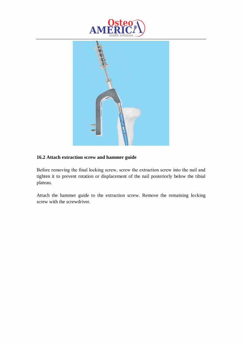
16.2 Attach extraction screw and hammer guide
Before removing the final locking screw, screw the extraction screw into the nail and
tighten it to prevent rotation or displacement of the nail posteriorly below the tibial
plateau.
Attach the hammer guide to the extraction screw. Remove the remaining locking
screw with the screwdriver.
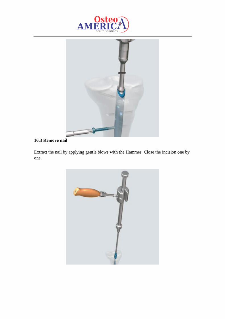
16.3 Remove nail
Extract the nail by applying gentle blows with the Hammer. Close the incision one by
one.