Embed Size (px)
Citation preview
OSCILLOSCOPE SELECTION GUIDE
TEK.COM | 1
CHOOSING YOUR OSCILLOSCOPE 1-3
MIXED SIGNAL AND MIXED DOMAIN OSCILLOSCOPES 4-5
MSO/DPO2000B 4
MDO3000 4
MDO4000C 5
ADVANCED SIGNAL ANALYSIS OSCILLOSCOPES 5-7
MSO/DPO5000B 5
DPO7000C Series 6
MSO/DPO70000 Series 6
DPO70000SX Series 7
SAMPLING OSCILLOSCOPES 7
DSA8300 7
BASIC OSCILLOSCOPES 8
TBS1000 8
TBS1000B/TBS1000B-EDU 8
TBS2000 8
BATTERY POWERED OSCILLOSCOPES
WITH ISOLATED CHANNELS 9
THS3000 9
TPS2000B 9
TDS SERIES OSCILLOSCOPES 9
TDS2000C 9
TDS3000C 9
OSCILLOSCOPE PROBES AND ACCESSORIES 10-11
REFERENCE LIBRARY 11
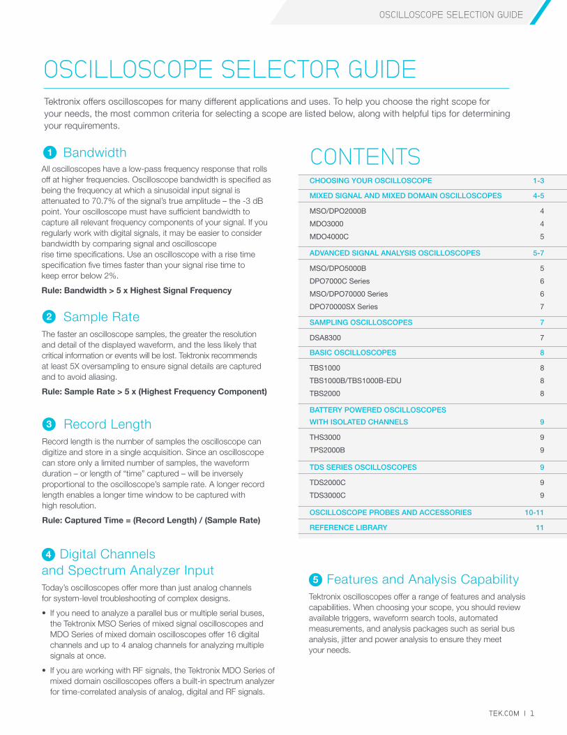
OSCILLOSCOPE SELECTOR GUIDETektronix offers oscilloscopes for many different applications and uses. To help you choose the right scope for your needs, the most common criteria for selecting a scope are listed below, along with helpful tips for determining your requirements.
BandwidthAll oscilloscopes have a low-pass frequency response that rolls off at higher frequencies. Oscilloscope bandwidth is specified as being the frequency at which a sinusoidal input signal is attenuated to 70.7% of the signal’s true amplitude – the -3 dB point. Your oscilloscope must have sufficient bandwidth to capture all relevant frequency components of your signal. If you regularly work with digital signals, it may be easier to consider bandwidth by comparing signal and oscilloscope rise time specifications. Use an oscilloscope with a rise time specification five times faster than your signal rise time to keep error below 2%.
Rule: Bandwidth > 5 x Highest Signal Frequency
4 Digital Channels and Spectrum Analyzer InputToday’s oscilloscopes offer more than just analog channels for system-level troubleshooting of complex designs.
• If you need to analyze a parallel bus or multiple serial buses, the Tektronix MSO Series of mixed signal oscilloscopes and MDO Series of mixed domain oscilloscopes offer 16 digital channels and up to 4 analog channels for analyzing multiple signals at once.
• If you are working with RF signals, the Tektronix MDO Series of mixed domain oscilloscopes offers a built-in spectrum analyzer for time-correlated analysis of analog, digital and RF signals.
1
Sample RateThe faster an oscilloscope samples, the greater the resolution and detail of the displayed waveform, and the less likely that critical information or events will be lost. Tektronix recommends at least 5X oversampling to ensure signal details are captured and to avoid aliasing.
Rule: Sample Rate > 5 x (Highest Frequency Component)
2
Record LengthRecord length is the number of samples the oscilloscope can digitize and store in a single acquisition. Since an oscilloscope can store only a limited number of samples, the waveform duration – or length of “time” captured – will be inversely proportional to the oscilloscope’s sample rate. A longer record length enables a longer time window to be captured with high resolution.
Rule: Captured Time = (Record Length) / (Sample Rate)
3
CONTENTS
5 Features and Analysis CapabilityTektronix oscilloscopes offer a range of features and analysis capabilities. When choosing your scope, you should review available triggers, waveform search tools, automated measurements, and analysis packages such as serial bus analysis, jitter and power analysis to ensure they meet your needs.
OSCILLOSCOPE SELECTION GUIDE
2 | TEK.COM
For an in-depth look at all of our products, including demos and 360-degree product explorers, please visit www.tektronix.com. All information on www.tektronix.com supersedes all other information.
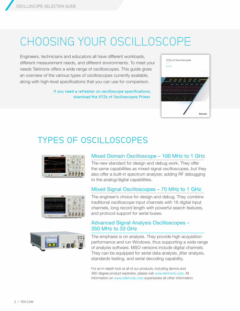
Engineers, technicians and educators all have different workloads, different measurement needs, and different environments. To meet your needs Tektronix offers a wide range of oscilloscopes. This guide gives an overview of the various types of oscilloscopes currently available, along with high-level specifications that you can use for comparison.
If you need a refresher on oscilloscope specifications, download the XYZs of Oscilloscopes Primer.
CHOOSING YOUR OSCILLOSCOPE
TYPES OF OSCILLOSCOPES
Mixed Domain Oscilloscope – 100 MHz to 1 GHz The new standard for design and debug work. They offer the same capabilities as mixed signal oscilloscopes, but they also offer a built-in spectrum analyzer, adding RF debugging to the analog/digital capabilities.
Mixed Signal Oscilloscopes – 70 MHz to 1 GHzThe engineer’s choice for design and debug. They combine traditional oscilloscope input channels with 16 digital input channels, long record length with powerful search features, and protocol support for serial buses.
Advanced Signal Analysis Oscilloscopes – 350 MHz to 33 GHz
The emphasis is on analysis. They provide high acquisition performance and run Windows, thus supporting a wide range of analysis software. MSO versions include digital channels. They can be equipped for serial data analysis, jitter analysis, standards testing, and serial decoding capability.
OSCILLOSCOPE SELECTION GUIDE
TEK.COM | 3
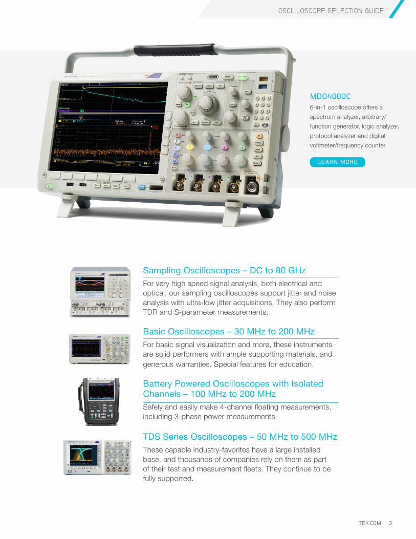
Sampling Oscilloscopes – DC to 80 GHzFor very high speed signal analysis, both electrical and optical, our sampling oscilloscopes support jitter and noise analysis with ultra-low jitter acquisitions. They also perform TDR and S-parameter measurements.
Basic Oscilloscopes – 30 MHz to 200 MHzFor basic signal visualization and more, these instruments are solid performers with ample supporting materials, and generous warranties. Special features for education.
Battery Powered Oscilloscopes with Isolated Channels – 100 MHz to 200 MHzSafely and easily make 4-channel floating measurements, including 3-phase power measurements
TDS Series Oscilloscopes – 50 MHz to 500 MHzThese capable industry-favorites have a large installed base, and thousands of companies rely on them as part of their test and measurement fleets. They continue to be fully supported.
MDO4000C 6-in-1 oscilloscope offers a
spectrum analyzer, arbitrary/
function generator, logic analyzer,
protocol analyzer and digital
voltmeter/frequency counter.
LEARN MORE
OSCILLOSCOPE SELECTION GUIDE
4 | TEK.COM
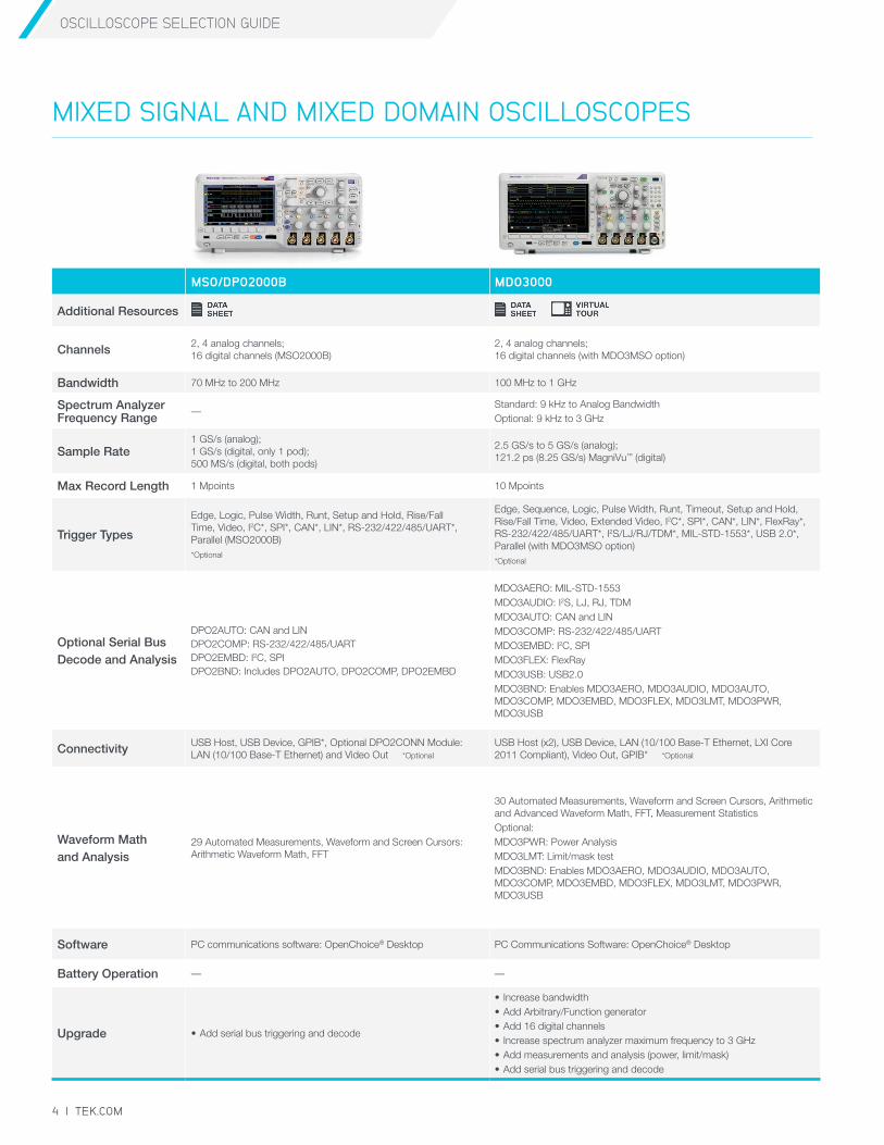
MIXED SIGNAL AND MIXED DOMAIN OSCILLOSCOPES
MSO/DPO2000B MDO3000
Additional Resources
Channels 2, 4 analog channels; 16 digital channels (MSO2000B)
2, 4 analog channels; 16 digital channels (with MDO3MSO option)
Bandwidth 70 MHz to 200 MHz 100 MHz to 1 GHz
Spectrum Analyzer Frequency Range
—Standard: 9 kHz to Analog BandwidthOptional: 9 kHz to 3 GHz
Sample Rate1 GS/s (analog); 1 GS/s (digital, only 1 pod); 500 MS/s (digital, both pods)
2.5 GS/s to 5 GS/s (analog); 121.2 ps (8.25 GS/s) MagniVu™ (digital)
Max Record Length 1 Mpoints 10 Mpoints
Trigger Types
Edge, Logic, Pulse Width, Runt, Setup and Hold, Rise/Fall Time, Video, I2C*, SPI*, CAN*, LIN*, RS-232/422/485/UART*, Parallel (MSO2000B)*Optional
Edge, Sequence, Logic, Pulse Width, Runt, Timeout, Setup and Hold, Rise/Fall Time, Video, Extended Video, I2C*, SPI*, CAN*, LIN*, FlexRay*, RS-232/422/485/UART*, I2S/LJ/RJ/TDM*, MIL-STD-1553*, USB 2.0*, Parallel (with MDO3MSO option)*Optional
Optional Serial Bus Decode and Analysis
DPO2AUTO: CAN and LINDPO2COMP: RS-232/422/485/UARTDPO2EMBD: I2C, SPIDPO2BND: Includes DPO2AUTO, DPO2COMP, DPO2EMBD
MDO3AERO: MIL-STD-1553 MDO3AUDIO: I2S, LJ, RJ, TDMMDO3AUTO: CAN and LINMDO3COMP: RS-232/422/485/UARTMDO3EMBD: I2C, SPI MDO3FLEX: FlexRayMDO3USB: USB2.0MDO3BND: Enables MDO3AERO, MDO3AUDIO, MDO3AUTO, MDO3COMP, MDO3EMBD, MDO3FLEX, MDO3LMT, MDO3PWR, MDO3USB
Connectivity USB Host, USB Device, GPIB*, Optional DPO2CONN Module: LAN (10/100 Base-T Ethernet) and Video Out *Optional
USB Host (x2), USB Device, LAN (10/100 Base-T Ethernet, LXI Core 2011 Compliant), Video Out, GPIB* *Optional
Waveform Math and Analysis
29 Automated Measurements, Waveform and Screen Cursors: Arithmetic Waveform Math, FFT
30 Automated Measurements, Waveform and Screen Cursors, Arithmetic and Advanced Waveform Math, FFT, Measurement StatisticsOptional: MDO3PWR: Power AnalysisMDO3LMT: Limit/mask test MDO3BND: Enables MDO3AERO, MDO3AUDIO, MDO3AUTO, MDO3COMP, MDO3EMBD, MDO3FLEX, MDO3LMT, MDO3PWR, MDO3USB
Software PC communications software: OpenChoice® Desktop PC Communications Software: OpenChoice® Desktop
Battery Operation — —
Upgrade • Add serial bus triggering and decode
• Increase bandwidth• Add Arbitrary/Function generator• Add 16 digital channels• Increase spectrum analyzer maximum frequency to 3 GHz• Add measurements and analysis (power, limit/mask)• Add serial bus triggering and decode
OSCILLOSCOPE SELECTION GUIDE
TEK.COM | 5
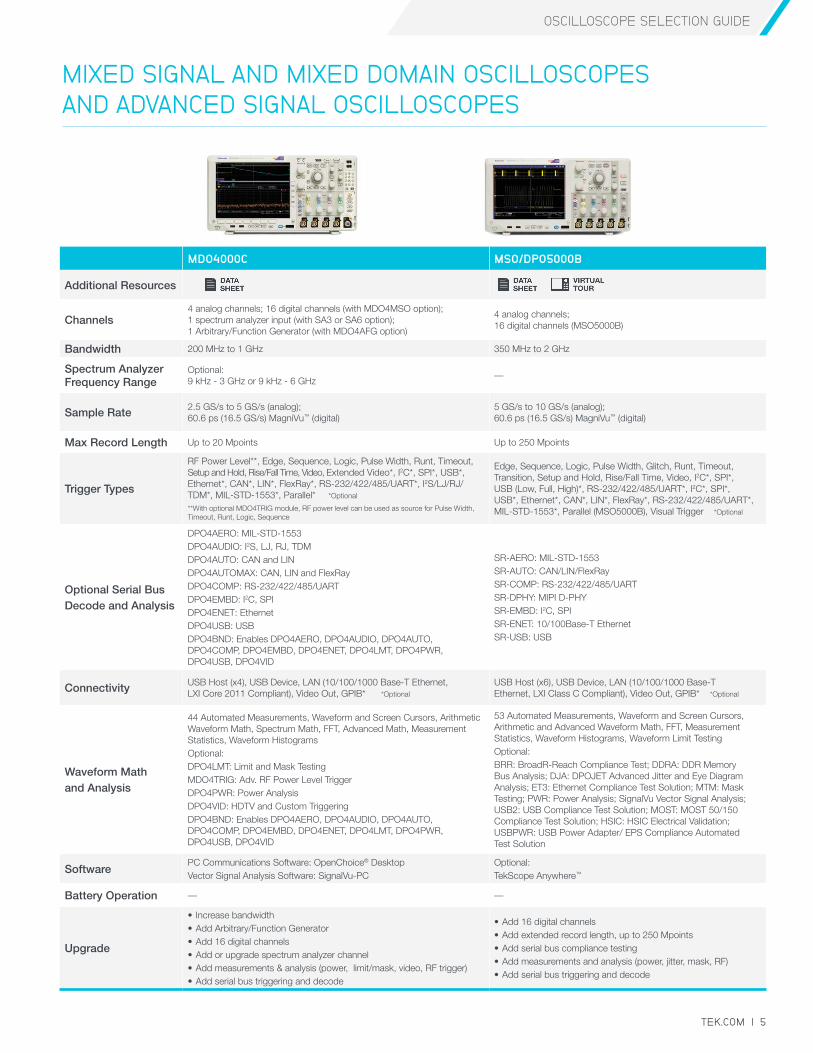
MIXED SIGNAL AND MIXED DOMAIN OSCILLOSCOPES AND ADVANCED SIGNAL OSCILLOSCOPES
MDO4000C MSO/DPO5000B
Additional Resources
Channels4 analog channels; 16 digital channels (with MDO4MSO option); 1 spectrum analyzer input (with SA3 or SA6 option); 1 Arbitrary/Function Generator (with MDO4AFG option)
4 analog channels; 16 digital channels (MSO5000B)
Bandwidth 200 MHz to 1 GHz 350 MHz to 2 GHz
Spectrum Analyzer Frequency Range
Optional: 9 kHz - 3 GHz or 9 kHz - 6 GHz
—
Sample Rate 2.5 GS/s to 5 GS/s (analog); 60.6 ps (16.5 GS/s) MagniVu™ (digital)
5 GS/s to 10 GS/s (analog); 60.6 ps (16.5 GS/s) MagniVu™ (digital)
Max Record Length Up to 20 Mpoints Up to 250 Mpoints
Trigger Types
RF Power Level**, Edge, Sequence, Logic, Pulse Width, Runt, Timeout, Setup and Hold, Rise/Fall Time, Video, Extended Video*, I2C*, SPI*, USB*, Ethernet*, CAN*, LIN*, FlexRay*, RS-232/422/485/UART*, I2S/LJ/RJ/TDM*, MIL-STD-1553*, Parallel* *Optional
**With optional MDO4TRIG module, RF power level can be used as source for Pulse Width, Timeout, Runt, Logic, Sequence
Edge, Sequence, Logic, Pulse Width, Glitch, Runt, Timeout, Transition, Setup and Hold, Rise/Fall Time, Video, I2C*, SPI*, USB (Low, Full, High)*, RS-232/422/485/UART*, I2C*, SPI*, USB*, Ethernet*, CAN*, LIN*, FlexRay*, RS-232/422/485/UART*, MIL-STD-1553*, Parallel (MSO5000B), Visual Trigger *Optional
Optional Serial Bus Decode and Analysis
DPO4AERO: MIL-STD-1553 DPO4AUDIO: I2S, LJ, RJ, TDM DPO4AUTO: CAN and LIN DPO4AUTOMAX: CAN, LIN and FlexRay DPO4COMP: RS-232/422/485/UART DPO4EMBD: I2C, SPI DPO4ENET: Ethernet DPO4USB: USB DPO4BND: Enables DPO4AERO, DPO4AUDIO, DPO4AUTO, DPO4COMP, DPO4EMBD, DPO4ENET, DPO4LMT, DPO4PWR, DPO4USB, DPO4VID
SR-AERO: MIL-STD-1553SR-AUTO: CAN/LIN/FlexRaySR-COMP: RS-232/422/485/UARTSR-DPHY: MIPI D-PHYSR-EMBD: I2C, SPI SR-ENET: 10/100Base-T Ethernet SR-USB: USB
Connectivity USB Host (x4), USB Device, LAN (10/100/1000 Base-T Ethernet, LXI Core 2011 Compliant), Video Out, GPIB* *Optional
USB Host (x6), USB Device, LAN (10/100/1000 Base-T Ethernet, LXI Class C Compliant), Video Out, GPIB* *Optional
Waveform Math and Analysis
44 Automated Measurements, Waveform and Screen Cursors, Arithmetic Waveform Math, Spectrum Math, FFT, Advanced Math, Measurement Statistics, Waveform Histograms Optional: DPO4LMT: Limit and Mask TestingMDO4TRIG: Adv. RF Power Level TriggerDPO4PWR: Power AnalysisDPO4VID: HDTV and Custom Triggering DPO4BND: Enables DPO4AERO, DPO4AUDIO, DPO4AUTO, DPO4COMP, DPO4EMBD, DPO4ENET, DPO4LMT, DPO4PWR, DPO4USB, DPO4VID
53 Automated Measurements, Waveform and Screen Cursors, Arithmetic and Advanced Waveform Math, FFT, Measurement Statistics, Waveform Histograms, Waveform Limit Testing Optional: BRR: BroadR-Reach Compliance Test; DDRA: DDR Memory Bus Analysis; DJA: DPOJET Advanced Jitter and Eye Diagram Analysis; ET3: Ethernet Compliance Test Solution; MTM: Mask Testing; PWR: Power Analysis; SignalVu Vector Signal Analysis; USB2: USB Compliance Test Solution; MOST: MOST 50/150 Compliance Test Solution; HSIC: HSIC Electrical Validation; USBPWR: USB Power Adapter/ EPS Compliance Automated Test Solution
SoftwarePC Communications Software: OpenChoice® DesktopVector Signal Analysis Software: SignalVu-PC
Optional: TekScope Anywhere™
Battery Operation — —
Upgrade
• Increase bandwidth• Add Arbitrary/Function Generator• Add 16 digital channels• Add or upgrade spectrum analyzer channel• Add measurements & analysis (power, limit/mask, video, RF trigger)• Add serial bus triggering and decode
• Add 16 digital channels• Add extended record length, up to 250 Mpoints• Add serial bus compliance testing• Add measurements and analysis (power, jitter, mask, RF)• Add serial bus triggering and decode
OSCILLOSCOPE SELECTION GUIDE
6 | TEK.COM
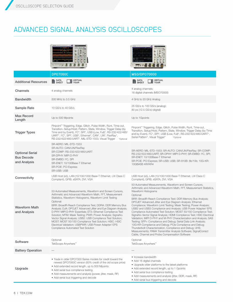
DPO7000C MSO/DPO70000
Additional Resources
Channels 4 analog channels4 analog channels;16 digital channels (MSO70000)
Bandwidth 500 MHz to 3.5 GHz 4 GHz to 33 GHz Analog
Sample Rate 10 GS/s to 40 GS/s25 GS/s to 100 GS/s (analog);80 ps (12.5 GS/s) (digital)
Max Record Length
Up to 500 Mpoints Up to 1Gpoints
Trigger Types
Pinpoint™ Triggering, Edge, Glitch, Pulse Width, Runt, Time-out, Transition. Setup/Hold, Pattern, State, Window, Trigger Delay (by Time and by Event), I2C*, SPI*, USB (Low, Full)*, RS-232/422/485/UART*, I2C*, SPI*, USB*, Ethernet*, CAN*, LIN*, FlexRay*, RS-232/422/485/UART*, MIL-STD-1553, Visual Trigger *Optional
Pinpoint™ Triggering, Edge, Glitch, Pulse Width, Runt, Time-out, Transition, Setup/Hold, Pattern, State, Window, Trigger Delay (by Time and by Event), I2C*, SPI*, USB (Low, Full)*, RS-232/422/485/UART*, Serial Pattern*, Visual Trigger* *Optional
Optional Serial Bus Decode and Analysis
SR-AERO: MIL-STD-1553SR-AUTO: CAN/LIN/FlexRaySR-COMP: RS-232/422/485/UARTSR-DPHY: MIPI D-PHYSR-EMBD: I2C, SPI SR-ENET: 10/100Base-T Ethernet SR-PCIE: PCI ExpressSR-USB: USB
SR-AERO: MIL-STD-1553; SR-AUTO: CAN/LIN/FlexRay; SR-COMP: RS-232/422/485/UART; SR-DPHY: MIPI D-PHY; SR-EMBD: I2C, SPI; SR-ENET: 10/100Base-T EthernetSR-PCIE: PCI Express; SR-USB: USB; SR-810B: 8b/10b; 10G-KR: 10GBASE-KR/KR4
Connectivity USB Host (x5), LAN (10/100/1000 Base-T Ethernet, LXI Class C Compliant), GPIB, eSATA, DVI, VGA
USB Host (x5), LAN (10/100/1000 Base-T Ethernet, LXI Class C Compliant), GPIB, eSATA, DVI, VGA
Waveform Math and Analysis
53 Automated Measurements, Waveform and Screen Cursors, Arithmetic and Advanced Waveform Math, FFT, Measurement Statistics, Waveform Histograms, Waveform Limit Testing Optional:BRR: BroadR-Reach Compliance Test; DDRA: DDR Memory Bus Analysis; DJA: DPOJET Advanced Jitter and Eye Diagram Analysis; D-PHY: MIPI D-PHY Essentials; ET3: Ethernet Compliance Test Solution; MTM: Mask Testing; PWR: Power Analysis; SignalVu Vector Signal Analysis; USB2: USB Compliance Test Solution; MOST: MOST 50/150 Compliance Test Solution; HSIC: HSIC Electrical Validation; USBPWR: USB Power Adapter/ EPS Compliance Automated Test Solution
53 Automated Measurements, Waveform and Screen Cursors, Arithmetic and Advanced Waveform Math, FFT, Measurement Statistics, Waveform Histograms Optional:BRR: BroadR-Reach Compliance Test; DDR Memory Bus Analysis; DPOJET Advanced Jitter and Eye Diagram Analysis; Ethernet Compliance; Waveform Limit Testing; Mask Testing; Power Analysis; USB2 and USB3 Compliance and Analysis; USB Power Adapter/ EPS Compliance Automated Test Solution; MOST 50/150 Compliance Test; SignalVu Vector Signal Analysis; HDMI Compliance Test; HSIC Electrical Validation; MIPI D-PHY and M-PHY Characterization and Analysis; SAS Testing; SFP+ Compliance and Debug; Serial Data Link Analysis; 10G-KR Compliance and Debug; PCIe Compliance and Debug; Thunderbolt Characterization, Compliance and Debug; UHS Measurements; PAM4 Transmitter Analysis Software; SignalCorrect Cable, Channel and Probe Compensation Software
SoftwareOptional:TekScope Anywhere™
Optional:TekScope Anywhere™
Battery Operation — —
Upgrade
• Trade in older DPO7000 Series models for credit toward the newest DPO7000C version (50% credit of the old scope price)
• Add extended record length, up to 500 Mpoints• Add serial bus compliance testing• Add measurements and analysis (power, jitter, mask, RF)• Add serial bus triggering and decode
• Increase bandwidth• Add 16 digital channels• Upgrade older platforms to the latest platforms• Add extended record length, up to 1 Gpoints• Add serial bus compliance testing• Add measurements and analysis (jitter, DDR, mask, RF)• Add serial bus triggering and decode
ADVANCED SIGNAL ANALYSIS OSCILLOSCOPES
OSCILLOSCOPE SELECTION GUIDE
TEK.COM | 7
DPO70000SX DSA8300
Additional Resources
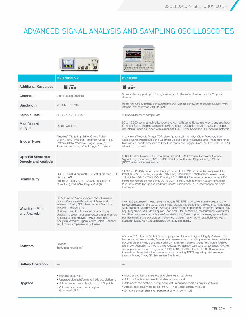
Channels 2 or 4 analog channels Six modules support up to 8 single ended or 4 differential channels and/or 2 optical channels
Bandwidth 23 GHz to 70 GHz Up to 70+ GHz Electrical bandwidth and 80+ Optical bandwidth modules available with intrinsic jitter as low as <100 fs RMS
Sample Rate 50 GS/s to 200 GS/s 300 ks/s Maximum sample rate
Max Record Length
Up to 1Gpoints50 to 16,000 per channel native record length; with up to 1M points when using available IConnect Signal Integrity Software, 10M samples (100k unit intervals, 100 samples per unit interval) when equipped with available 80SJNB Jitter, Noise and BER Analysis software
Trigger Types
Pinpoint™ Triggering, Edge, Glitch, Pulse Width, Runt, Time-out, Transition, Setup/Hold, Pattern, State, Window, Trigger Delay (by Time and by Event), Visual Trigger* *Optional
Clock Input/Prescale Trigger, TDR clock (generated internally), Clock Recovery from Optical Sampling modules and Electrical Clock Recovery modules, and Phase Reference time base supports acquisitions Free Run mode and Trigger Direct Input for <100 fs RMS intrinsic jitter typical
Optional Serial Bus Decode and Analysis
—80SJNB Jitter, Noise, BER, Serial Data Link and PAM4 Analysis Software; IConnect Signal Integrity Software; 100GBASE-SR4 Transmitter and Dispersion Eye Closure (TDEC) automation test solution
Connectivity
USB2.0 Host (4 on front)/3.0 Host (4 on rear), USB Device, LAN (10/100/1000 Base-T Ethernet, LXI Class C Compliant), DVI, VGA, DisplayPort (2)
3 USB 2.0 Port(s) connector on the front panel, 4 USB 2.0 Ports on the rear panel; LAN PORT, RJ-45 connector, supports 10BASE-T, 100BASE-T, 1000BASE-T on rear panel; 1 Serial Port, DB-9 COM1, COM2 ports; 1 DVI IEEE488.2 connector on rear panel; 1 DVI connector, female on rear panel, DVI to VGA 15-pin D-sub connector adapter provided; PS2 Serial Ports Mouse and keyboard inputs; Audio Ports 1/8 in. microphone input and line output
Waveform Math and Analysis
53 Automated Measurements, Waveform and Screen Cursors, Arithmetic and Advanced Waveform Math, FFT, Measurement Statistics, Waveform Histograms Optional: DPOJET Advanced Jitter and Eye Diagram Analysis; SignalVu Vector Signal Analysis; Serial Data Link Analysis; PAM4 Transmitter Analysis Software; SignalCorrect Cable, Channel and Probe Compensation Software
Over 120 automated measurements include RZ, NRZ, and pulse signal types, and the following measurement types, plus 8 math waveforms using the following math functions: Add, Subtract, Multiply, Divide, Average, Differentiate, Exponential, Integrate, Natural Log, Log, Magnitude, Min, Max, Square Root, and Filter. In addition, measurement values can be utilized as scalars in math waveform definitions; Mask support for many applications, standard masks are available as predefined, built-in masks; Automated Masked Margin based on Mask Hit Ratio as required by many standards.
SoftwareOptional:TekScope Anywhere™
Windows® 7 Ultimate (32-bit) Operating System; IConnect Signal Integrity Software for frequency domain analysis, S-parameter measurements, and impedance characterization 80SJNB Jitter, Noise, BER, and Serial Link analysis including Cross-Talk aware TJ (BUJ and PAM4 Analysis); 80SJARB Jitter Analysis of Arbitrary Data with J2-J9 measurements, and support for pattern lengths to PRBS31; 100GBASE-SR4 (IEEE 802.3bm) optical transmitter characterization measurements, including TDEC, signaling rate, Average Launch Power, OMA, ER, Transmitter Eye Mask
Battery Operation — —
Upgrade
• Increase bandwidth• Upgrade older platforms to the latest platforms• Add extended record length, up to 1 G points• Add measurements and analysis
(jitter, mask, RF)
• Modular architecture lets you add channels or bandwidth• Add TDR, optical and electrical standards support• Add advanced analysis, compliance test, frequency domain analysis software • Add clock recovery trigger pickoff (CRTP) to select optical modules • Enhance system jitter floor performance to <100 fs RMS
ADVANCED SIGNAL ANALYSIS AND SAMPLING OSCILLOSCOPES
OSCILLOSCOPE SELECTION GUIDE
8 | TEK.COM
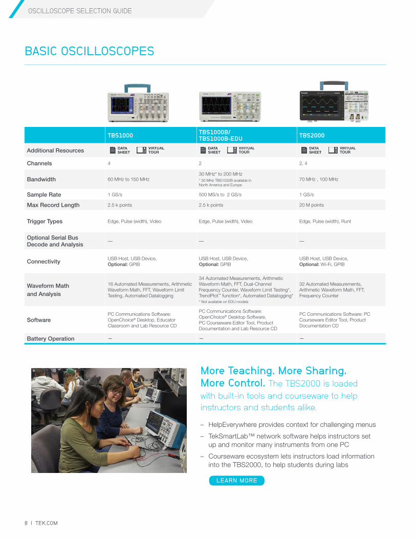
TBS1000 TBS1000B/ TBS1000B-EDU TBS2000
Additional Resources
Channels 4 2 2, 4
Bandwidth 60 MHz to 150 MHz30 MHz* to 200 MHz* 30 MHz TBS1032B available in North America and Europe
70 MHz , 100 MHz
Sample Rate 1 GS/s 500 MS/s to 2 GS/s 1 GS/s
Max Record Length 2.5 k points 2.5 k points 20 M points
Trigger Types Edge, Pulse (width), Video Edge, Pulse (width), Video Edge, Pulse (width), Runt
Optional Serial Bus Decode and Analysis
— — —
Connectivity USB Host, USB Device, Optional: GPIB
USB Host, USB Device, Optional: GPIB
USB Host, USB Device, Optional: Wi-Fi, GPIB
Waveform Math and Analysis
16 Automated Measurements, Arithmetic Waveform Math, FFT, Waveform Limit Testing, Automated Datalogging
34 Automated Measurements, Arithmetic Waveform Math, FFT, Dual-Channel Frequency Counter, Waveform Limit Testing*, TrendPlot™ function*, Automated Datalogging** Not available on EDU models
32 Automated Measurements, Arithmetic Waveform Math, FFT, Frequency Counter
SoftwarePC Communications Software: OpenChoice® Desktop, Educator Classroom and Lab Resource CD
PC Communications Software: OpenChoice® Desktop Software, PC Courseware Editor Tool, Product Documentation and Lab Resource CD
PC Communications Software: PC Courseware Editor Tool, Product Documentation CD
Battery Operation — — —
BASIC OSCILLOSCOPESBASIC OSCILLOSCOPES
More Teaching. More Sharing. More Control. The TBS2000 is loaded with built-in tools and courseware to help instructors and students alike.
– HelpEverywhere provides context for challenging menus
– TekSmartLab™ network software helps instructors set up and monitor many instruments from one PC
– Courseware ecosystem lets instructors load information into the TBS2000, to help students during labs
LEARN MORE
OSCILLOSCOPE SELECTION GUIDE
TEK.COM | 9
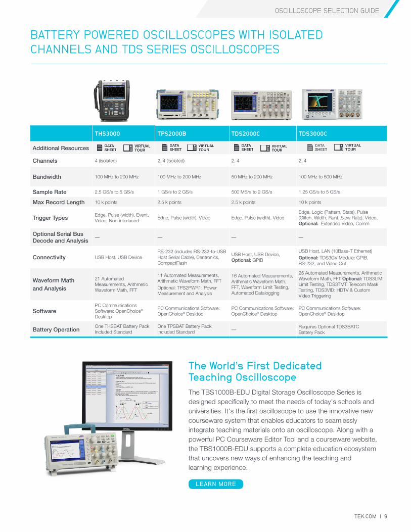
THS3000 TPS2000B TDS2000C TDS3000C
Additional Resources
Channels 4 (isolated) 2, 4 (isolated) 2, 4 2, 4
Bandwidth 100 MHz to 200 MHz 100 MHz to 200 MHz 50 MHz to 200 MHz 100 MHz to 500 MHz
Sample Rate 2.5 GS/s to 5 GS/s 1 GS/s to 2 GS/s 500 MS/s to 2 GS/s 1.25 GS/s to 5 GS/s
Max Record Length 10 k points 2.5 k points 2.5 k points 10 k points
Trigger Types Edge, Pulse (width), Event, Video, Non-interlaced
Edge, Pulse (width), Video Edge, Pulse (width), VideoEdge, Logic (Pattern, State), Pulse (Glitch, Width, Runt, Slew Rate), Video, Optional: Extended Video, Comm
Optional Serial Bus Decode and Analysis
— — — —
Connectivity USB Host, USB DeviceRS-232 (includes RS-232-to-USB Host Serial Cable), Centronics, CompactFlash
USB Host, USB Device, Optional: GPIB
USB Host, LAN (10Base-T Ethernet)Optional: TDS3GV Module: GPIB, RS-232, and Video Out
Waveform Math and Analysis
21 Automated Measurements, Arithmetic Waveform Math, FFT
11 Automated Measurements, Arithmetic Waveform Math, FFTOptional: TPS2PWR1: Power Measurement and Analysis
16 Automated Measurements, Arithmetic Waveform Math, FFT, Waveform Limit Testing, Automated Datalogging
25 Automated Measurements, Arithmetic Waveform Math, FFT Optional: TDS3LIM: Limit Testing, TDS3TMT: Telecom Mask Testing, TDS3VID: HDTV & Custom Video Triggering
SoftwarePC Communications Software: OpenChoice® Desktop
PC Communications Software: OpenChoice® Desktop
PC Communications Software: OpenChoice® Desktop
PC Communications Software: OpenChoice® Desktop
Battery OperationOne THSBAT Battery Pack Included Standard
One TPSBAT Battery Pack Included Standard —
Requires Optional TDS3BATC Battery Pack
BATTERY POWERED OSCILLOSCOPES WITH ISOLATED CHANNELS AND TDS SERIES OSCILLOSCOPES
The World’s First Dedicated Teaching OscilloscopeThe TBS1000B-EDU Digital Storage Oscilloscope Series is designed specifically to meet the needs of today's schools and universities. It's the first oscilloscope to use the innovative new courseware system that enables educators to seamlessly integrate teaching materials onto an oscilloscope. Along with a powerful PC Courseware Editor Tool and a courseware website, the TBS1000B-EDU supports a complete education ecosystem that uncovers new ways of enhancing the teaching and learning experience.
LEARN MORE
OSCILLOSCOPE SELECTION GUIDE
10 | TEK.COM
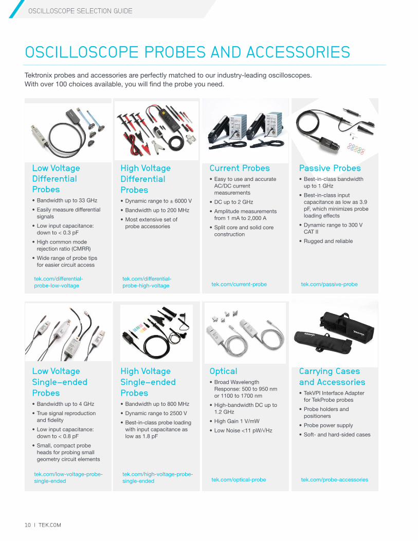
Low Voltage Differential Probes• Bandwidth up to 33 GHz
• Easily measure differential signals
• Low input capacitance: down to < 0.3 pF
• High common mode rejection ratio (CMRR)
• Wide range of probe tips for easier circuit access
Low Voltage Single-ended Probes• Bandwidth up to 4 GHz
• True signal reproduction and fidelity
• Low input capacitance: down to < 0.8 pF
• Small, compact probe heads for probing small geometry circuit elements
Current Probes• Easy to use and accurate
AC/DC current measurements
• DC up to 2 GHz
• Amplitude measurements from 1 mA to 2,000 A
• Split core and solid core construction
Optical• Broad Wavelength
Response: 500 to 950 nm or 1100 to 1700 nm
• High-bandwidth DC up to 1.2 GHz
• High Gain 1 V/mW
• Low Noise <11 pW/√Hz
High Voltage Differential Probes• Dynamic range to ± 6000 V
• Bandwidth up to 200 MHz
• Most extensive set of probe accessories
High Voltage Single-ended Probes• Bandwidth up to 800 MHz
• Dynamic range to 2500 V
• Best-in-class probe loading with input capacitance as low as 1.8 pF
Carrying Cases and Accessories• TekVPI Interface Adapter
for TekProbe probes
• Probe holders and positioners
• Probe power supply
• Soft- and hard-sided cases
tek.com/probe-accessories
tek.com/passive-probetek.com/current-probetek.com/differential- probe-high-voltage
tek.com/differential- probe-low-voltage
tek.com/optical-probetek.com/high-voltage-probe-single-ended
tek.com/low-voltage-probe-single-ended
OSCILLOSCOPE PROBES AND ACCESSORIESTektronix probes and accessories are perfectly matched to our industry-leading oscilloscopes. With over 100 choices available, you will find the probe you need.
Passive Probes• Best-in-class bandwidth
up to 1 GHz
• Best-in-class input capacitance as low as 3.9 pF, which minimizes probe loading effects
• Dynamic range to 300 V CAT II
• Rugged and reliable
OSCILLOSCOPE SELECTION GUIDE
TEK.COM | 11
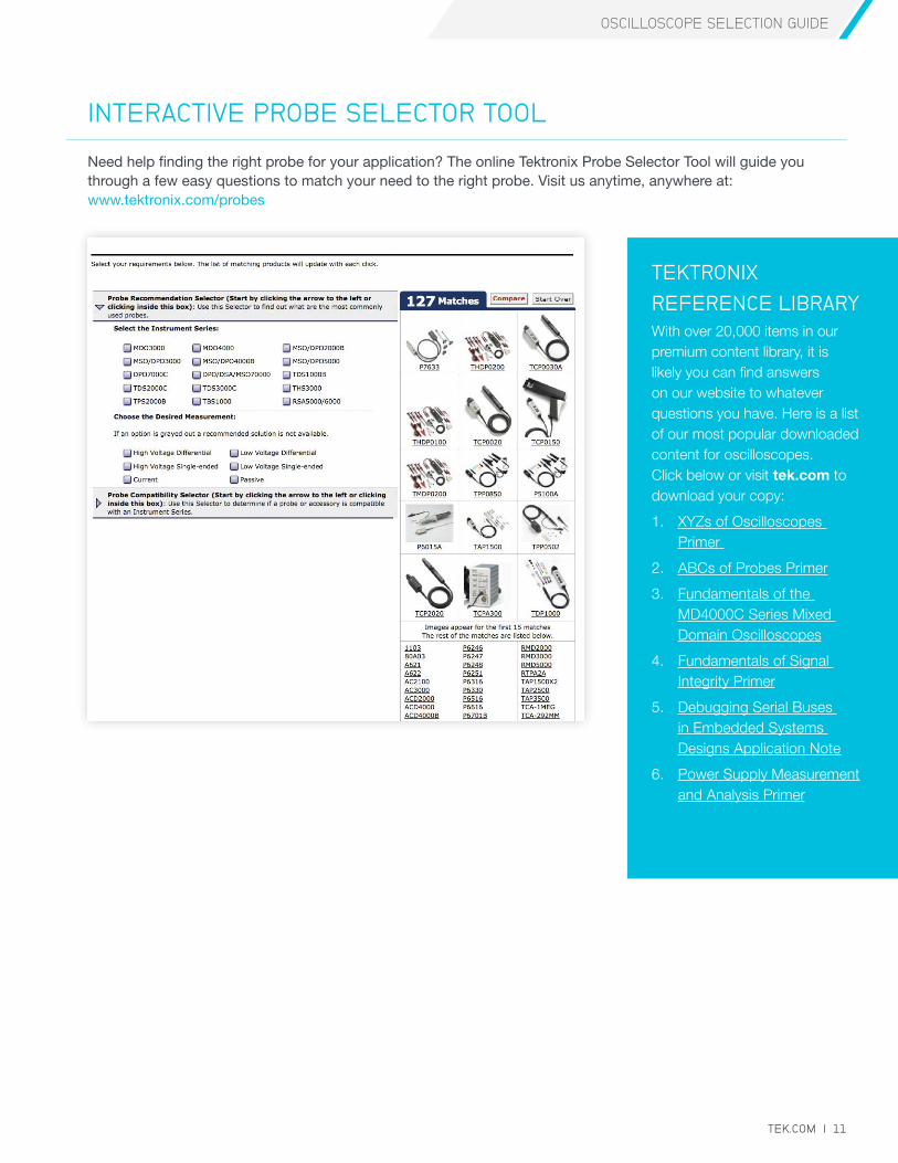
Need help finding the right probe for your application? The online Tektronix Probe Selector Tool will guide you through a few easy questions to match your need to the right probe. Visit us anytime, anywhere at: www.tektronix.com/probes
INTERACTIVE PROBE SELECTOR TOOL
TEKTRONIX
REFERENCE LIBRARYWith over 20,000 items in our premium content library, it is likely you can find answers on our website to whatever questions you have. Here is a list of our most popular downloaded content for oscilloscopes. Click below or visit tek.com to download your copy:
1. XYZs of Oscilloscopes Primer
2. ABCs of Probes Primer
3. Fundamentals of the MD4000C Series Mixed Domain Oscilloscopes
4. Fundamentals of Signal Integrity Primer
5. Debugging Serial Buses in Embedded Systems Designs Application Note
6. Power Supply Measurement and Analysis Primer
Contact Information: Australia* 1 800 709 465
Austria 00800 2255 4835
Balkans, Israel, South Africa and other ISE Countries +41 52 675 3777
Belgium* 00800 2255 4835
Brazil +55 (11) 3759 7627
Canada 1 800 833 9200
Central East Europe / Baltics +41 52 675 3777
Central Europe / Greece +41 52 675 3777
Denmark +45 80 88 1401
Finland +41 52 675 3777
France* 00800 2255 4835
Germany* 00800 2255 4835
Hong Kong 400 820 5835
India 000 800 650 1835
Indonesia 007 803 601 5249
Italy 00800 2255 4835
Japan 81 (3) 6714 3010
Luxembourg +41 52 675 3777
Malaysia 1 800 22 55835
Mexico, Central/South America and Caribbean 52 (55) 56 04 50 90
Middle East, Asia, and North Africa +41 52 675 3777
The Netherlands* 00800 2255 4835
New Zealand 0800 800 238
Norway 800 16098
People’s Republic of China 400 820 5835
Philippines 1 800 1601 0077
Poland +41 52 675 3777
Portugal 80 08 12370
Republic of Korea +82 2 6917 5000
Russia / CIS +7 (495) 6647564
Singapore 800 6011 473
South Africa +41 52 675 3777
Spain* 00800 2255 4835
Sweden* 00800 2255 4835
Switzerland* 00800 2255 4835
Taiwan 886 (2) 2656 6688
Thailand 1 800 011 931
United Kingdom / Ireland* 00800 2255 4835
USA 1 800 833 9200
Vietnam 12060128
* European toll-free number. If not accessible, call: +41 52 675 3777
Find more valuable resources at TEK.COM
Copyright © Tektronix. All rights reserved. Tektronix products are covered by U.S. and foreign patents, issued and pending. Information in this publication supersedes that in all previously published material. Specification and price change privileges reserved. TEKTRONIX and TEK are registered trademarks of Tektronix, Inc. All other trade names referenced are the service marks, trademarks or registered trademarks of their respective companies.
090916. AH 146W-31080-1