Embed Size (px)
Citation preview

IM0085 2016-‐10
for the Electronics Inc. #2 Almen Gage and Almen Gage Jr
2 Electronics Inc. • (574) 256-‐5001 • www.electronics-‐inc.com
Description ................................................................................................................................................................... 3
TSP-‐3 Almen Gage ................................................................................................................................................... 3 TSP-‐Jr Almen Gage .................................................................................................................................................. 3
Requirements ............................................................................................................................................................... 3 Forms ....................................................................................................................................................................... 3 Equipment ................................................................................................................................................................ 3 SAE J442 #2 Almen Gage Construction .................................................................................................................... 4
Instructions for Calibration of TSP-‐3 Almen Gage ...................................................................................................... 5 Inspection ................................................................................................................................................................. 5 Ball and Post Position Measurement Check ............................................................................................................. 5 Minimum Ball Height Check ..................................................................................................................................... 6 Ball Plane Flatness Check ......................................................................................................................................... 6 Indicator Battery ...................................................................................................................................................... 7 As Found .................................................................................................................................................................. 7 As Found Spindle Starting Position .......................................................................................................................... 7 Step Block Readings ................................................................................................................................................. 7 As Returned .............................................................................................................................................................. 8 Curved Check Block .................................................................................................................................................. 8 Paperwork ................................................................................................................................................................ 8
TSP-‐3 Certification of Calibration (Metric) ........................................................................................................... 9 TSP-‐3 Certification of Calibration (English) ........................................................................................................ 10
Instructions for Calibration of Almen Gage Jr ........................................................................................................... 11 Inspection ............................................................................................................................................................... 11 Ball and Post Position Measurement Check ........................................................................................................... 12 Minimum Ball Height Check ................................................................................................................................... 12 Ball Plane Flatness Check ....................................................................................................................................... 13 As Found ................................................................................................................................................................ 13 As Found Bezel – Spindle Starting Position ............................................................................................................ 13 Step Block Readings ............................................................................................................................................... 13 As Returned ............................................................................................................................................................ 14 Flat Check Block ..................................................................................................................................................... 14 Paperwork .............................................................................................................................................................. 14
TSP-‐Jr Certification of Calibration (Metric) ........................................................................................................ 15 TSP-‐Jr Certification of Calibration (English) ........................................................................................................ 16
Replacement Parts ..................................................................................................................................................... 17 Calibration Services ................................................................................................................................................... 18 Contacting Electronics Inc. ......................................................................................................................................... 18
Table of Contents
Electronics Inc. • (574) 256-‐5001 • www.electronics-‐inc.com 3
Description
The Almen Calibration Kit Instruction Manual is intended for individuals skilled in the use of the measuring equipment described herein. The manual is based upon recommendations from ISO 10012-‐1. This procedure will confirm Almen gage compliance with requirements of the following specifications.
TSP-‐3 Almen Gage TSP-‐Jr Almen Gage
Digital Indicator Analog Indicator • SAE J442 • SAE AMS 2430 • SAE AMS 2432 • Boeing BAC 5730
• MIL-‐S-‐13165 • SAE AMS-‐S-‐13165
Requirements SAE J442 Test Strip, Holder and Gage for Shot Peening and SAE AMS 2432 Shot Peening, Computer Monitored are the primary references used for the construction and calibration of the TSP-‐3 Almen gage. J442 is the primary specification and AMS 2432 includes tighter tolerances for aerospace applications. AMS-‐S-‐13165, successor to MIL-‐S-‐13165, is the primary reference for the Almen Gage Jr. Note: Both of these documents have been canceled but may still be used if desired. The cancellation notice recommends users use AMS 2430 that defers to J442 for Almen gage requirements. Note: This procedure must be performed in an environment with temperature in the range of 60˚F -‐ 90˚F (16˚C -‐ 32˚C) and a relative humidity of 30% -‐ 90%.
Forms The results of the calibration procedure can be documented in the Certification of Calibration forms found in this manual. Both Metric and English versions are provided.
Equipment The calibration kit includes:
• 9-‐hole template for the inspection of the position of the balls, posts and indicator tip • Five (5) step blocks (either Metric or English) to check the accuracy of the indicator • Commercial-‐grade .05 mm feeler gage to check the ball plane flatness
The 9-‐hole template also serves as the certified 2.0 mm feeler gage for ball height inspection. Any commercial-‐grade feeler gage of .05 mm may be used. The feeler gage is for reference only and is not certified. The step blocks may also be purchased individually. See “Replacement Parts” in this manual.
4 Electronics Inc. • (574) 256-‐5001 • www.electronics-‐inc.com
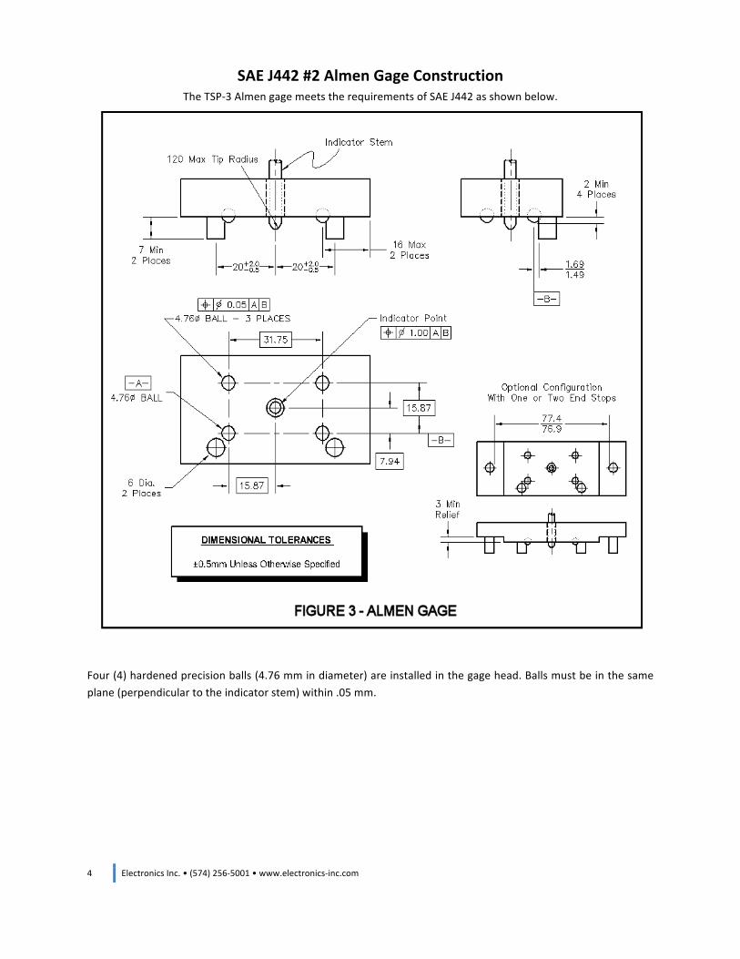
SAE J442 #2 Almen Gage Construction The TSP-‐3 Almen gage meets the requirements of SAE J442 as shown below.
Four (4) hardened precision balls (4.76 mm in diameter) are installed in the gage head. Balls must be in the same plane (perpendicular to the indicator stem) within .05 mm.
Electronics Inc. • (574) 256-‐5001 • www.electronics-‐inc.com 5
Instructions for Calibration of TSP-‐3 Almen Gage Make a copy of the Certification of Calibration form (Metric or English) provided in this manual. Note: Do not repair, adjust or replace any items until the “Attribute” and “As Found” readings are completed. Record the Serial Number of the Almen gage and its step block on the form. Record the Serial Numbers, Certified Values and Calibration Due Dates for the five (5) step blocks and 9-‐hole template.
Inspection Indicator Free Movement -‐ Check the indicator stylus for free movement and full range of travel. If the indicator stylus sticks, the gage must be repaired. Record “Pass” or “Fail” in the column of the form. Record any notes if necessary. Indicator Tip -‐ Without the use of magnification, look for signs of wear or damage. Replace the indicator tip if there is wear or damage. For example, a flat spot of 1 mm (0.039 inch) requires the replacement of the indicator tip. Record “Pass” or “Fail” in the column of the form. Use the Notes column to record repairs or replacements. Ball Condition -‐ Inspect the magnetic strength of the four balls. Verify there is sufficient attraction to hold the test strip securely in place. If not, replace entire gage head. Inspect the condition of four balls. If there are flat spots greater than 1.0 mm (0.039 inch) in diameter on top of any ball, the gage head must be repaired or replaced. Record “Pass” or “Fail” in the column of the form. Use the Notes column to record repairs or replacements. Post Condition -‐ Without the use of magnification, inspect the posts for signs of wear. If grooves on the posts could prevent the test strip from being properly seated, the posts should be rotated or replaced. To rotate the posts: Press the posts out from the bottom of the gage head, rotate them approximately 180 degrees, and press them back into the gage head. Record “Pass” or “Fail” in the column of the form. Use the Notes column to record any repairs or replacements.
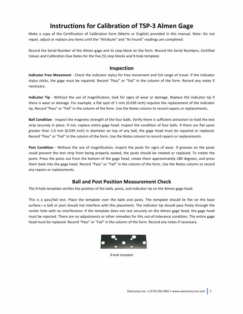
Ball and Post Position Measurement Check The 9-‐hole template verifies the position of the balls, posts, and indicator tip on the Almen gage head. This is a pass/fail test. Place the template over the balls and posts. The template should lie flat on the base surface—a ball or post should not interfere with this placement. The indicator tip should pass freely through the center hole with no interference. If the template does not rest securely on the Almen gage head, the gage head must be rejected. There are no adjustments or other remedies for this out-‐of-‐tolerance condition. The entire gage head must be replaced. Record “Pass” or “Fail” in the column of the form. Record any notes if necessary.
9-‐hole template

6 Electronics Inc. • (574) 256-‐5001 • www.electronics-‐inc.com
Minimum Ball Height Check The 9-‐hole template is certified to be a minimum of 2.00 mm in thickness. It is used to verify the ball heights are equal to or greater than 2.00 mm in height. This is a pass/fail test. Place a certified flat surface, such as a step block or the flat side of the curved check block, on the Almen gage head and attempt to insert the 2.00 mm template between the gage head and the flat surface. If the template cannot be inserted, the ball height is less than 2.00 mm and the gage head must be replaced. Record “Pass” or “Fail” in the column of the form. Record any notes if necessary.
The 9-‐hole template verifies that the ball heights are at least 2.00 mm in height
Ball Plane Flatness Check This is a pass/fail test. Place a certified flat surface, such as the flat side of the curved check block, on the gage head to determine if one of the balls is lower than the other three balls. Check if the gap is larger than 0.05 mm by attempting to insert a 0.05 mm feeler gage between any one of the four balls and the flat surface. If the feeler gage can be inserted between any ball and the flat surface while the remaining three balls are in contact with the flat surface, the ball plane flatness exceeds the tolerance and the gage head must be replaced. Record “Pass” or “Fail” in the column of the form. Record any notes if necessary.
A 0.05 mm feeler gage verifies the ball plane flatness is within tolerance
Electronics Inc. • (574) 256-‐5001 • www.electronics-‐inc.com 7
Indicator Battery Batteries should be replaced annually or during calibration. The warning symbol “bA Lo” appears on the digital indicator when the batteries are low. Two (2) CR2450 lithium cells are required. Set-‐up and calibration information are saved during battery replacement.
As Found The “As Found” readings are the initial observations of the gage. These are made before any adjustments are made (including adjustments to the Spindle Starting Position) and entered into the appropriate cell on the Certification form. If no adjustments are made, these values are then copied into the “As Returned” columns of the form. Note: If adjustments are made, the new value must be within tolerance allowed and entered into the “As Returned” section. If adjustments cannot bring the gage reading into the allowed tolerance, the gage must be returned for repair to Electronics Inc.
As Found Spindle Starting Position
Read and record the Spindle Starting Position in the “As Found” column before making any step block readings. Do not adjust the Spindle Starting Position regardless of the setting since this could affect the actual “As Found” conditions for other measurements. Place a calibrated flat surface, such as a step block or the flat side of the curved check block, on the Almen gage head. Press and hold the “ZERO/ON” button to place the indicator into the True Spindle Position mode (the “x1” on the bottom of the indicator screen will disappear). The value now shown in the display is the Spindle Starting Position.
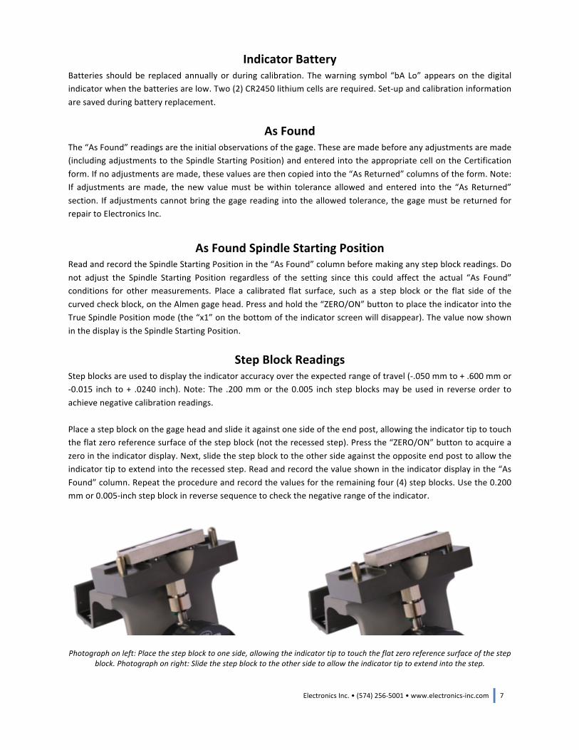
Step Block Readings Step blocks are used to display the indicator accuracy over the expected range of travel (-‐.050 mm to + .600 mm or -‐0.015 inch to + .0240 inch). Note: The .200 mm or the 0.005 inch step blocks may be used in reverse order to achieve negative calibration readings. Place a step block on the gage head and slide it against one side of the end post, allowing the indicator tip to touch the flat zero reference surface of the step block (not the recessed step). Press the “ZERO/ON” button to acquire a zero in the indicator display. Next, slide the step block to the other side against the opposite end post to allow the indicator tip to extend into the recessed step. Read and record the value shown in the indicator display in the “As Found” column. Repeat the procedure and record the values for the remaining four (4) step blocks. Use the 0.200 mm or 0.005-‐inch step block in reverse sequence to check the negative range of the indicator.
Photograph on left: Place the step block to one side, allowing the indicator tip to touch the flat zero reference surface of the step block. Photograph on right: Slide the step block to the other side to allow the indicator tip to extend into the step.
8 Electronics Inc. • (574) 256-‐5001 • www.electronics-‐inc.com
As Returned Any features that failed during the inspection procedure must be repaired or replaced at this time. The factory recommended value of the Spindle Starting Position is set to 0.000 mm ± 0.025 mm (0.000 inch ± 0.002 inch). If the spindle setting is out of tolerance, it should be adjusted before recording the remaining “As Returned” values of the step blocks. Note: Spindle Starting Position is not a requirement of J442. It is a factory recommended practice. Therefore, if the Spindle Starting Position is not within the recommended range, it should not fail its inspection. However, the Spindle Starting Position should be set to the recommended range as stated above before the gage is returned to service. To adjust the Spindle Starting Position: Place a calibrated flat surface, such as a step block or the flat side of the curved check block, on the Almen gage head. Press and hold the “ZERO/ON” button to place the indicator into the True Spindle Position mode (the “x1” on the bottom of the indicator screen will disappear). Loosen the 8 mm gland nut that holds the indicator and adjust the indicator placement on the frame until the Spindle Starting Position is within tolerance. Carefully tighten the gland nut and be sure the indicator is secure (does not move or rotate) and the Spindle Starting Position does not change as the gland nut is tightened. Record the adjusted Spindle Starting Position in the “As Returned” column. Place a dab of proof lacquer at the gland nut and stem as a tamper-‐proof seal. Place each of the five (5) step blocks on the gage and record the “As Returned” values on the Certificate of Calibration. The step block readings must be within ± 0.0025 mm (± 0.0001 inch) of the step block value. Adjust the indicator span as described in the Indicator Owner’s Manual or replace the indicator if a step block reading fails.
Curved Check Block A Curved Check Block is supplied with the TSP-‐3 #2 Almen gage. It is flat on one side and curved on the other. The flat side is precision lapped to a flatness of 2 HLB (2 Helium Light Bands) or better, and is used to set the zero datum reference for the gage. The curved side is not calibrated but has a curvature that will represent an arc height of approximately .600 mm ± .05 mm or .024 inch ± .02 inch, which is the upper range of the intended use of the gage. The curved side is used as a weekly check to verify that the gage is still functioning as intended. A Certification of Calibration for flatness for the flat side is included with the Curved Check Block. The curved side is not certified. It is for reference only. Zero the gage by using a certified flat surface (such as one of the certified step blocks). Place the flat side of the Curved Check Block on the gage. If the reading exceeds ± .005 mm (± .0002 inch), reject the block and replace it with a new Curved Check Block.
Paperwork Indicate next calibration due date and sign and date the Certification of Calibration. Fill out and place a “Calibrated” decal on the gage with the date of calibration. The next calibration due date will depend upon quality system calibration requirements which is usually a date one year later. Some organizations allow calibration one year after first use in the event the gage is placed into inventory prior to use.

Electronics Inc. • (574) 256-‐5001 • www.electronics-‐inc.com 9
TSP-‐3 Certification of Calibration (Metric) (Qualifies for SAE J442, AMS 2430, AMS 2432, and BOEING BAC5730)
Model: TSP-‐3 Manufactured by Electronics Inc. Mishawaka, Indiana USA
Serial Number Procedure: IM0085
Attribute Pass / Fail Notes Indicator Free Movement Indicator Tip (Max. 1.0 mm Dia. Flat) Ball Condition (Max. 1.0 mm Dia. Flat) Post Condition (No Grooves) Ball and Post Position (9-‐Hole Template) Minimum Ball Height (2.0 mm) Ball plane Flatness (.05 mm)
Spindle Starting Position
Recommended ± 0.025 mm As Found As Returned
Step block readings must be within ± 0.0025 mm of the Certified Value
Size Serial Number Calibration Due Date Certified Value As Found As Returned .6 mm .5 mm .4 mm .3 mm .2 mm -‐.2 mm Same as above Same as above Same as above
Old Serial Number New Serial Number New Gage Head – (Separate certification supplied) New Check Block – (Separate certification supplied) We hereby certify that this instrument has been inspected and is in conformity with the requirements of AMS 2432 Next calibration due date: ______________________________
Performed by Date
Equipment Serial Number Calibration Due Date 9-‐Hole Template
Serial Number As Found Tolerance Pass/Fail Curved Check Block 0 + .005 mm (0 ±.0002”)
10 Electronics Inc. • (574) 256-‐5001 • www.electronics-‐inc.com
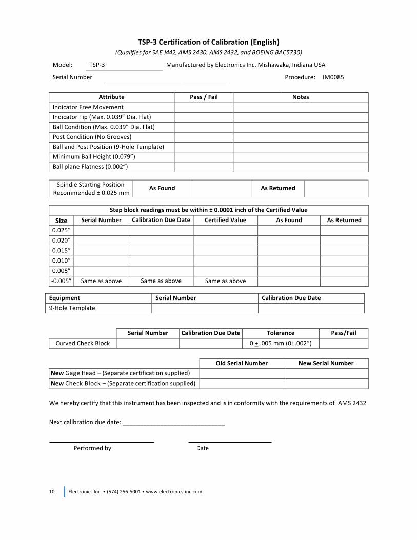
TSP-‐3 Certification of Calibration (English) (Qualifies for SAE J442, AMS 2430, AMS 2432, and BOEING BAC5730)
Model: TSP-‐3 Manufactured by Electronics Inc. Mishawaka, Indiana USA
Serial Number Procedure: IM0085
Attribute Pass / Fail Notes Indicator Free Movement Indicator Tip (Max. 0.039” Dia. Flat) Ball Condition (Max. 0.039” Dia. Flat) Post Condition (No Grooves) Ball and Post Position (9-‐Hole Template) Minimum Ball Height (0.079”) Ball plane Flatness (0.002”)
Spindle Starting Position Recommended ± 0.025 mm
As Found As Returned
Step block readings must be within ± 0.0001 inch of the Certified Value
Size Serial Number Calibration Due Date Certified Value As Found As Returned 0.025” 0.020” 0.015” 0.010” 0.005” -‐0.005” Same as above Same as above Same as above
Old Serial Number New Serial Number New Gage Head – (Separate certification supplied) New Check Block – (Separate certification supplied) We hereby certify that this instrument has been inspected and is in conformity with the requirements of AMS 2432 Next calibration due date: ______________________________
Performed by Date
Equipment Serial Number Calibration Due Date 9-‐Hole Template
Serial Number Calibration Due Date Tolerance Pass/Fail Curved Check Block 0 + .005 mm (0±.002”)
Electronics Inc. • (574) 256-‐5001 • www.electronics-‐inc.com 11
Instructions for Calibration of Almen Gage Jr Make a copy of the Certification of Calibration form (Metric or English) provided in this manual. Do not repair, adjust or replace any items until the “Attribute” and “As Found” readings are completed. Note: Almen gage TSP-‐Jr is qualified to MIL-‐S-‐13165 and AMS-‐S-‐13165 only. Record the Serial Number of the Almen gage and Flat Check Block on the form. Record the Serial Number and Calibration Due Dates for the five (5) step blocks and 9-‐hole template.
Inspection Some of the inspection steps listed below are recommended practices by Electronics Incorporated, not requirements of AMS-‐S-‐13165. These items are identified as “EI” on the certification form. Items required by 13165 are identified by “13165”. Indicator Free Movement -‐ Check the indicator stylus for free movement and full range of travel. If the indicator sticks, the indicator must be replaced. Record “Pass” or “Fail” in the column of the form. Record any notes if necessary. Indicator Tip -‐ Without the use of magnification, look for signs of wear or damage. Replace the indicator tip if there is wear or damage. For example, a flat spot of 1 mm (0.039 inch) requires the replacement of the indicator tip. Record “Pass” or “Fail” in the column of the form. Use the Notes column to record any repairs or replacements. Ball Condition -‐ Inspect the magnetic strength of the four balls. Verify there is sufficient attraction to hold the test strip in place securely. If not, replace entire gage head. Inspect the condition of four balls. Wear or flat spots greater than 1.0 mm (0.039 inch) in diameter on top of the ball will require repair or replacement of the gage head. Record “Pass” or “Fail” in the column of the form. Use the Notes column to record any repairs or replacements. Post Condition -‐ Without the use of magnification, inspect the posts for signs of wear. If wear on the posts could prevent the test strip from being properly seated, the posts should be rotated or replaced. The posts may be rotated so that a smooth surface is in contact with the strip. To rotate the posts: Press the posts out from the bottom of the gage head and rotate them approximately 180 degrees and press them back into the gage head. Record “Pass” or “Fail” in the column of the form. Use the Notes column to record any repairs or replacements.
12 Electronics Inc. • (574) 256-‐5001 • www.electronics-‐inc.com
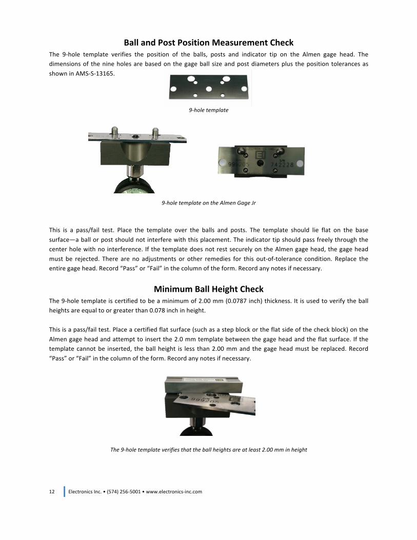
Ball and Post Position Measurement Check The 9-‐hole template verifies the position of the balls, posts and indicator tip on the Almen gage head. The dimensions of the nine holes are based on the gage ball size and post diameters plus the position tolerances as shown in AMS-‐S-‐13165.
9-‐hole template
9-‐hole template on the Almen Gage Jr This is a pass/fail test. Place the template over the balls and posts. The template should lie flat on the base surface—a ball or post should not interfere with this placement. The indicator tip should pass freely through the center hole with no interference. If the template does not rest securely on the Almen gage head, the gage head must be rejected. There are no adjustments or other remedies for this out-‐of-‐tolerance condition. Replace the entire gage head. Record “Pass” or “Fail” in the column of the form. Record any notes if necessary.
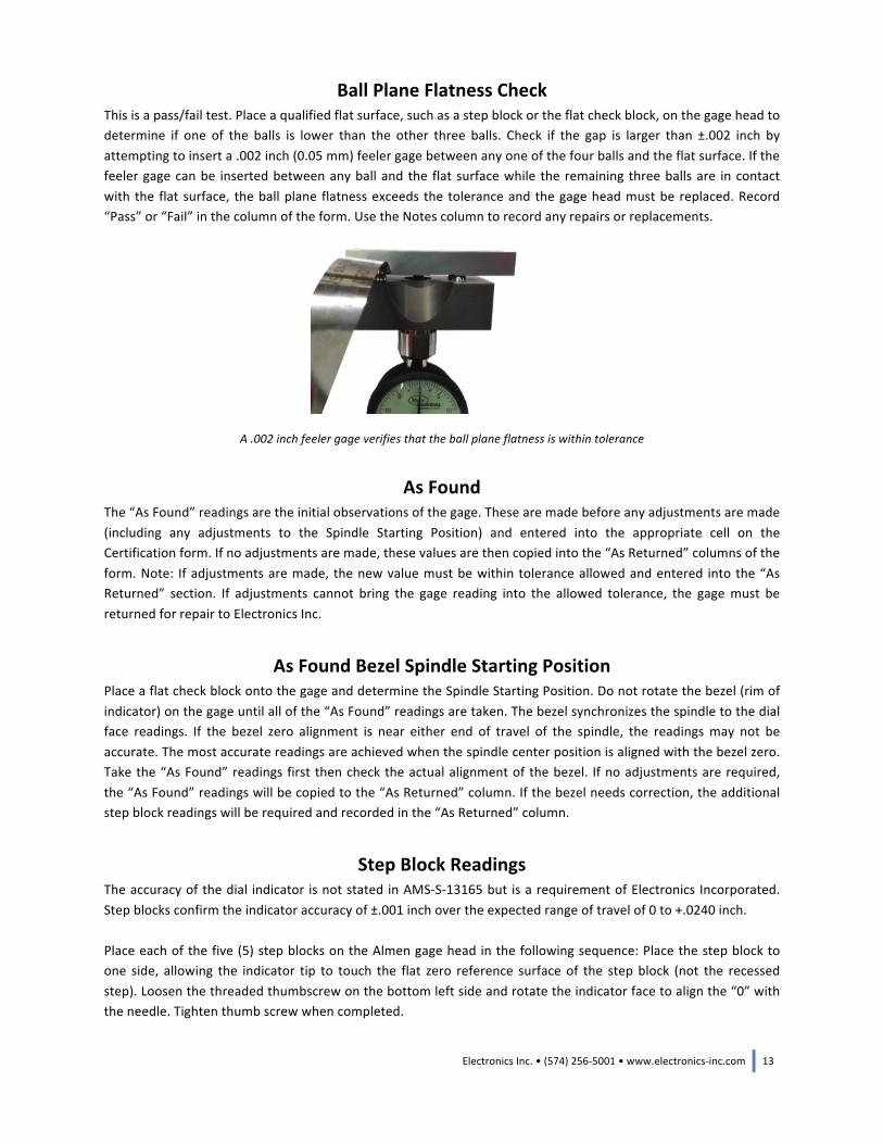
Minimum Ball Height Check The 9-‐hole template is certified to be a minimum of 2.00 mm (0.0787 inch) thickness. It is used to verify the ball heights are equal to or greater than 0.078 inch in height. This is a pass/fail test. Place a certified flat surface (such as a step block or the flat side of the check block) on the Almen gage head and attempt to insert the 2.0 mm template between the gage head and the flat surface. If the template cannot be inserted, the ball height is less than 2.00 mm and the gage head must be replaced. Record “Pass” or “Fail” in the column of the form. Record any notes if necessary.
The 9-‐hole template verifies that the ball heights are at least 2.00 mm in height
Electronics Inc. • (574) 256-‐5001 • www.electronics-‐inc.com 13
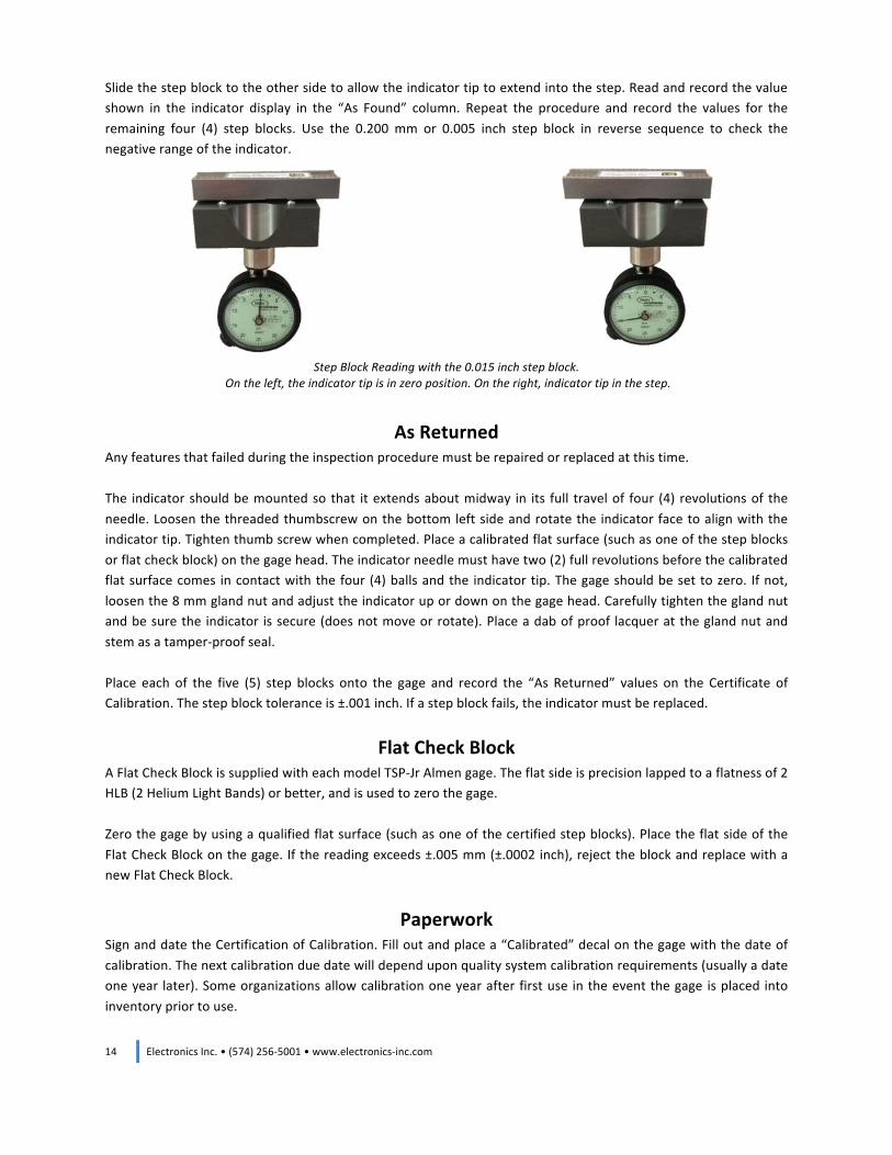
Ball Plane Flatness Check This is a pass/fail test. Place a qualified flat surface, such as a step block or the flat check block, on the gage head to determine if one of the balls is lower than the other three balls. Check if the gap is larger than ±.002 inch by attempting to insert a .002 inch (0.05 mm) feeler gage between any one of the four balls and the flat surface. If the feeler gage can be inserted between any ball and the flat surface while the remaining three balls are in contact with the flat surface, the ball plane flatness exceeds the tolerance and the gage head must be replaced. Record “Pass” or “Fail” in the column of the form. Use the Notes column to record any repairs or replacements.
A .002 inch feeler gage verifies that the ball plane flatness is within tolerance
As Found
The “As Found” readings are the initial observations of the gage. These are made before any adjustments are made (including any adjustments to the Spindle Starting Position) and entered into the appropriate cell on the Certification form. If no adjustments are made, these values are then copied into the “As Returned” columns of the form. Note: If adjustments are made, the new value must be within tolerance allowed and entered into the “As Returned” section. If adjustments cannot bring the gage reading into the allowed tolerance, the gage must be returned for repair to Electronics Inc.
As Found Bezel Spindle Starting Position
Place a flat check block onto the gage and determine the Spindle Starting Position. Do not rotate the bezel (rim of indicator) on the gage until all of the “As Found” readings are taken. The bezel synchronizes the spindle to the dial face readings. If the bezel zero alignment is near either end of travel of the spindle, the readings may not be accurate. The most accurate readings are achieved when the spindle center position is aligned with the bezel zero. Take the “As Found” readings first then check the actual alignment of the bezel. If no adjustments are required, the “As Found” readings will be copied to the “As Returned” column. If the bezel needs correction, the additional step block readings will be required and recorded in the “As Returned” column.
Step Block Readings
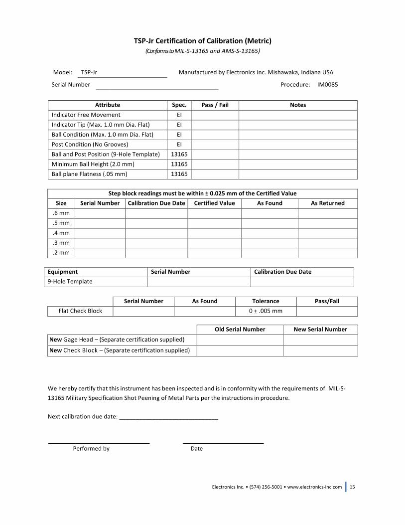
The accuracy of the dial indicator is not stated in AMS-‐S-‐13165 but is a requirement of Electronics Incorporated. Step blocks confirm the indicator accuracy of ±.001 inch over the expected range of travel of 0 to +.0240 inch. Place each of the five (5) step blocks on the Almen gage head in the following sequence: Place the step block to one side, allowing the indicator tip to touch the flat zero reference surface of the step block (not the recessed step). Loosen the threaded thumbscrew on the bottom left side and rotate the indicator face to align the “0” with the needle. Tighten thumb screw when completed.
14 Electronics Inc. • (574) 256-‐5001 • www.electronics-‐inc.com
Slide the step block to the other side to allow the indicator tip to extend into the step. Read and record the value shown in the indicator display in the “As Found” column. Repeat the procedure and record the values for the remaining four (4) step blocks. Use the 0.200 mm or 0.005 inch step block in reverse sequence to check the negative range of the indicator.
Step Block Reading with the 0.015 inch step block. On the left, the indicator tip is in zero position. On the right, indicator tip in the step.
As Returned
Any features that failed during the inspection procedure must be repaired or replaced at this time. The indicator should be mounted so that it extends about midway in its full travel of four (4) revolutions of the needle. Loosen the threaded thumbscrew on the bottom left side and rotate the indicator face to align with the indicator tip. Tighten thumb screw when completed. Place a calibrated flat surface (such as one of the step blocks or flat check block) on the gage head. The indicator needle must have two (2) full revolutions before the calibrated flat surface comes in contact with the four (4) balls and the indicator tip. The gage should be set to zero. If not, loosen the 8 mm gland nut and adjust the indicator up or down on the gage head. Carefully tighten the gland nut and be sure the indicator is secure (does not move or rotate). Place a dab of proof lacquer at the gland nut and stem as a tamper-‐proof seal. Place each of the five (5) step blocks onto the gage and record the “As Returned” values on the Certificate of Calibration. The step block tolerance is ±.001 inch. If a step block fails, the indicator must be replaced.
Flat Check Block A Flat Check Block is supplied with each model TSP-‐Jr Almen gage. The flat side is precision lapped to a flatness of 2 HLB (2 Helium Light Bands) or better, and is used to zero the gage. Zero the gage by using a qualified flat surface (such as one of the certified step blocks). Place the flat side of the Flat Check Block on the gage. If the reading exceeds ±.005 mm (±.0002 inch), reject the block and replace with a new Flat Check Block.
Paperwork Sign and date the Certification of Calibration. Fill out and place a “Calibrated” decal on the gage with the date of calibration. The next calibration due date will depend upon quality system calibration requirements (usually a date one year later). Some organizations allow calibration one year after first use in the event the gage is placed into inventory prior to use.
Electronics Inc. • (574) 256-‐5001 • www.electronics-‐inc.com 15
TSP-‐Jr Certification of Calibration (Metric) (Conforms to MIL-‐S-‐13165 and AMS-‐S-‐13165)
Model: TSP-‐Jr Manufactured by Electronics Inc. Mishawaka, Indiana USA
Serial Number Procedure: IM0085
Attribute Spec. Pass / Fail Notes
Indicator Free Movement EI Indicator Tip (Max. 1.0 mm Dia. Flat) EI Ball Condition (Max. 1.0 mm Dia. Flat) EI Post Condition (No Grooves) EI Ball and Post Position (9-‐Hole Template) 13165 Minimum Ball Height (2.0 mm) 13165 Ball plane Flatness (.05 mm) 13165
Step block readings must be within ± 0.025 mm of the Certified Value
Size Serial Number Calibration Due Date Certified Value As Found As Returned .6 mm .5 mm .4 mm .3 mm .2 mm
Old Serial Number New Serial Number New Gage Head – (Separate certification supplied)
New Check Block – (Separate certification supplied)
We hereby certify that this instrument has been inspected and is in conformity with the requirements of MIL-‐S-‐13165 Military Specification Shot Peening of Metal Parts per the instructions in procedure. Next calibration due date: ______________________________
Performed by Date
Equipment Serial Number Calibration Due Date 9-‐Hole Template
Serial Number As Found Tolerance Pass/Fail Flat Check Block 0 + .005 mm
16 Electronics Inc. • (574) 256-‐5001 • www.electronics-‐inc.com
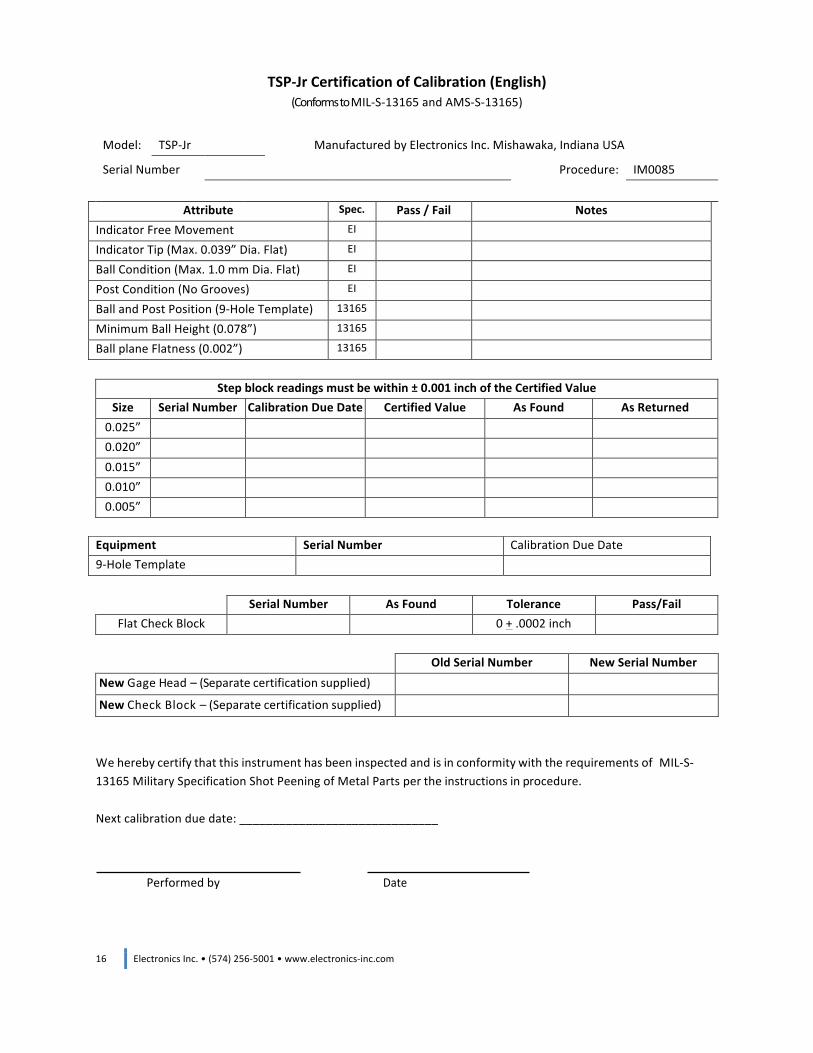
TSP-‐Jr Certification of Calibration (English) (Conforms to MIL-‐S-‐13165 and AMS-‐S-‐13165)
Model: TSP-‐Jr Manufactured by Electronics Inc. Mishawaka, Indiana USA
Serial Number Procedure: IM0085
Attribute Spec. Pass / Fail Notes
Indicator Free Movement EI Indicator Tip (Max. 0.039” Dia. Flat) EI Ball Condition (Max. 1.0 mm Dia. Flat) EI Post Condition (No Grooves) EI Ball and Post Position (9-‐Hole Template) 13165 Minimum Ball Height (0.078”) 13165 Ball plane Flatness (0.002”) 13165
Step block readings must be within ± 0.001 inch of the Certified Value
Size Serial Number Calibration Due Date Certified Value As Found As Returned 0.025” 0.020” 0.015” 0.010” 0.005”
Old Serial Number New Serial Number New Gage Head – (Separate certification supplied)
New Check Block – (Separate certification supplied) We hereby certify that this instrument has been inspected and is in conformity with the requirements of MIL-‐S-‐13165 Military Specification Shot Peening of Metal Parts per the instructions in procedure. Next calibration due date: ______________________________
Performed by Date
Equipment Serial Number Calibration Due Date 9-‐Hole Template
Serial Number As Found Tolerance Pass/Fail Flat Check Block 0 + .0002 inch
Electronics Inc. • (574) 256-‐5001 • www.electronics-‐inc.com 17
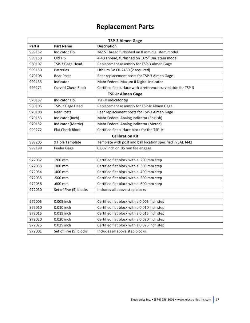
Replacement Parts
TSP-‐3 Almen Gage Part # Part Name Description 999152 Indicator Tip M2.5 Thread furbished on 8 mm dia. stem model 999158 Old Tip 4-‐48 Thread, furbished on .375” Dia. stem model 980107 TSP-‐3 Gage Head Replacement assembly for TSP-‐3 Almen Gage 999150 Batteries Lithium 3V CR-‐2450 (2 required) 970108 Rear Posts Rear replacement posts for TSP-‐3 Almen Gage 999155 Indicator Mahr Federal Maxµm II Digital Indicator 999271 Curved Check Block Certified flat surface with a reference curved side for TSP-‐3
TSP-‐Jr Almen Gage 970157 Indicator Tip TSP-‐Jr indicator tip 980106 TSP-‐Jr Gage Head Replacement assembly for TSP-‐Jr Almen Gage 970108 Rear Posts Rear replacement posts for TSP-‐3 Almen Gage 970153 Indicator (Inch) Mahr Federal Analog Indicator (English) 970152 Indicator (Metric) Mahr Federal Analog Indicator (Metric) 999272 Flat Check Block Certified flat surface block for the TSP-‐Jr
Calibration Kit 999205 9 Hole Template Template with post and ball location specified in SAE J442 999198 Feeler Gage 0.002 inch or .05 mm feeler gage 972032 .200 mm Certified flat block with a .200 mm step 972033 .300 mm Certified flat block with a .300 mm step 972034 .400 mm Certified flat block with a .400 mm step 972035 .500 mm Certified flat block with a .500 mm step 972036 .600 mm Certified flat block with a .600 mm step 972030 Set of Five (5) blocks Includes all above step blocks 972005 0.005 inch Certified flat block with a 0.005 inch step 972010 0.010 inch Certified flat block with a 0.010 inch step 972015 0.015 inch Certified flat block with a 0.015 inch step 972020 0.020 inch Certified flat block with a 0.020 inch step 972025 0.025 inch Certified flat block with a 0.025 inch step 972001 Set of Five (5) blocks Includes all above step blocks

18 Electronics Inc. • (574) 256-‐5001 • www.electronics-‐inc.com
Calibration Services The Almen Gage Calibration Kit should be re-‐calibrated every three (3) years, or sooner if conditions warrant. The original factory certifications will expire three (3) years after the date of shipment. Customers are urged to place the Calibration Kit into a scheduled calibration routine. Electronics Incorporated provides calibration services in accordance with the applicable requirements of ANSI/NCSL Z-‐540-‐1 (formerly MIL-‐STD-‐45662A, ISO/IEC 17025). To arrange for calibration service, contact Electronics Inc. by phone or email: 1-‐800-‐832-‐5653 (USA and Canada) or 574-‐256-‐5001 or sales@electronics-‐inc.com.
Contacting Electronics Inc.
Mailing and Shipping Address: Electronics Inc.
56790 Magnetic Drive Mishawaka, IN 46545 USA
Telephone: 1-‐800-‐832-‐5653 (Toll-‐free in USA and Canada) or (574) 256-‐5001
Fax: (574) 256-‐5222
Email: sales@electronics-‐inc.com Website: www.electronics-‐inc.com
For repairs and/or return instructions, please call our Customer Service department at 1-‐800-‐832-‐5653 (Toll-‐free in USA and Canada) or (574) 256-‐5001. Electronics Inc. makes no representations or warranties, either expressed or implied, with respect to the contents of this publication or the products that it describes, and specifically disclaims any implied warranties of merchantability or fitness for any particular purpose. Electronics Inc. reserves the right to revise this publication and to make changes and improvements to the products described in this publication without the obligation of Electronics Inc. to notify any person or organization of such revisions, changes, or improvements.


![LQ $UL]RQD - azwvgs.org pdfs/2018_04_Tidbits.pdf · 4if ipmet b # " jo fevdbujpo gspn .ponpvui $pmmfhf 1sjps up npwjoh up "sj[pob jo +fbo ubvhiu hfofbmphz boe mfduvsfe jo *oejbob](https://img.pdfslide.net/doc/110x75/5bfd40c309d3f2fe708c9015/lq-ulrqd-pdfs201804tidbitspdf-4if-ipmet-b-jo-fevdbujpo-gspn-ponpvui.jpg)