Embed Size (px)
Citation preview
Overpressure Scenariosand
Required Relief RatesPART I
Required Data
• Procure latest PIDs
• Heat and Mass Balance Report
• Rotating Equipment Datasheet (performance curves, etc.)
• Vessel and Heat Exchanger Datasheets (drawings)
• Operating/Emergency procedures
• Review current project specific document-Relief & Blowdown Philosophy
Overpressure Scenario Identification
• Start with PIDs and PFDs
• Analyze on equipment-by-equipment basis
• Typically start at front end of process
• Identify sources of feed & its maximum pressure
• Identify all heat input sources including external fire
• No credit for favorable instrument or operator response
• Include comments to explain rationale
Industry Guidelines
• API RP 521
• API 2000
• Project Specific Guidelines
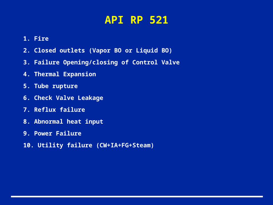
API RP 521
1. Fire
2. Closed outlets (Vapor BO or Liquid BO)
3. Failure Opening/closing of Control Valve
4. Thermal Expansion
5. Tube rupture
6. Check Valve Leakage
7. Reflux failure
8. Abnormal heat input
9. Power Failure
10. Utility failure (CW+IA+FG+Steam)
External Fire
Causes:
1.Explosion caused by the ignition of a flammable leaking gas
2. Leakage of flammable hydrocarbon inventory
Applicability Guidelines
• Equipment must be located with in a fire zone
• Some portion of the equipment must be located below the maximum fire height (API RP 521 uses 25 feet)
• In some cases, the time required to reach relief pressure may render the scenario not credible
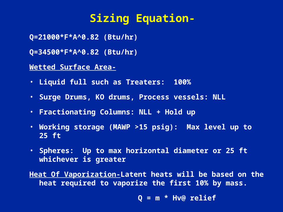
Sizing Equation-
Q=21000*F*A^0.82 (Btu/hr)
Q=34500*F*A^0.82 (Btu/hr)
Wetted Surface Area-
• Liquid full such as Treaters: 100%
• Surge Drums, KO drums, Process vessels: NLL
• Fractionating Columns: NLL + Hold up
• Working storage (MAWP >15 psig): Max level up to 25 ft
• Spheres: Up to max horizontal diameter or 25 ft whichever is greater
Heat Of Vaporization-Latent heats will be based on the heat required to vaporize the first 10% by mass.
Q = m * Hv@ relief
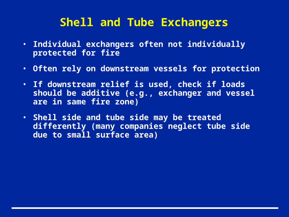
• Individual exchangers often not individually protected for fire
• Often rely on downstream vessels for protection
• If downstream relief is used, check if loads should be additive (e.g., exchanger and vessel are in same fire zone)
• Shell side and tube side may be treated differently (many companies neglect tube side due to small surface area)
Shell and Tube Exchangers
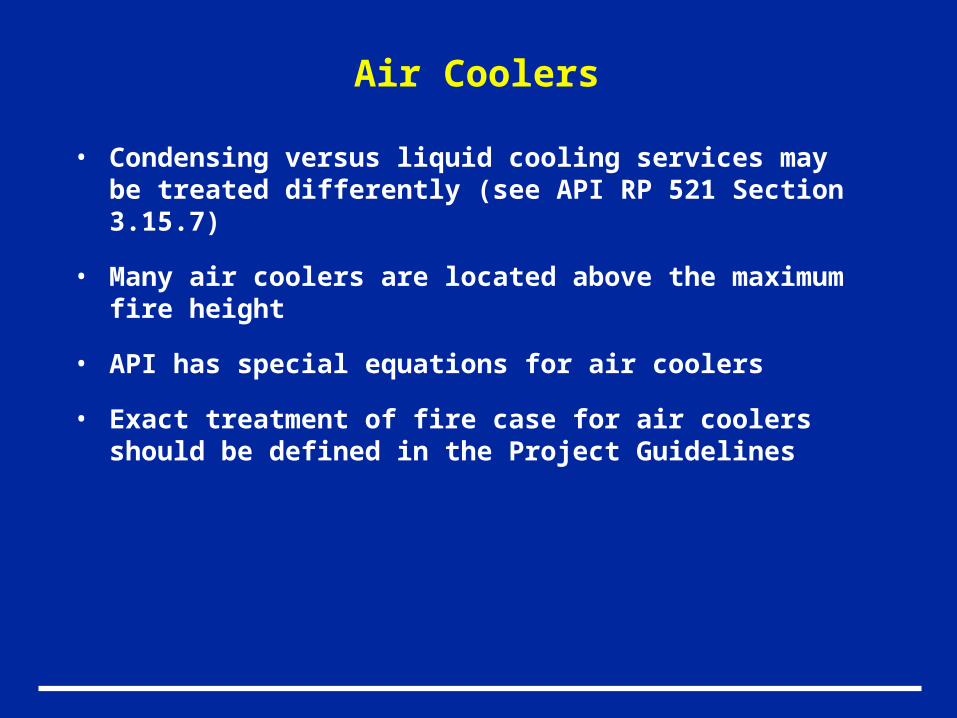
Air Coolers
• Condensing versus liquid cooling services may be treated differently (see API RP 521 Section 3.15.7)
• Many air coolers are located above the maximum fire height
• API has special equations for air coolers
• Exact treatment of fire case for air coolers should be defined in the Project Guidelines
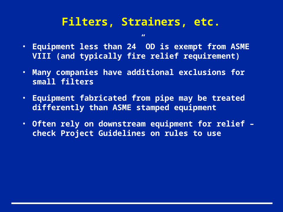
Filters, Strainers, etc.
• Equipment less than 24” OD is exempt from ASME VIII (and typically fire relief requirement)
• Many companies have additional exclusions for small filters
• Equipment fabricated from pipe may be treated differently than ASME stamped equipment
• Often rely on downstream equipment for relief – check Project Guidelines on rules to use
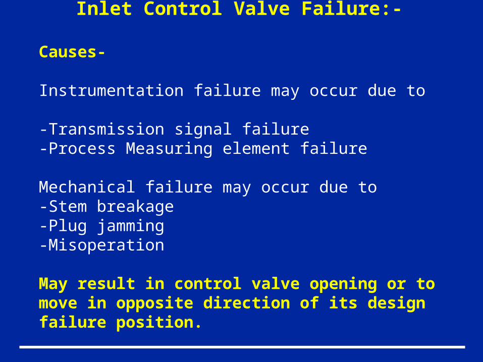
Inlet Control Valve Failure:-
Causes-
Instrumentation failure may occur due to
-Transmission signal failure-Process Measuring element failure
Mechanical failure may occur due to-Stem breakage-Plug jamming-Misoperation
May result in control valve opening or to move in opposite direction of its design failure position.
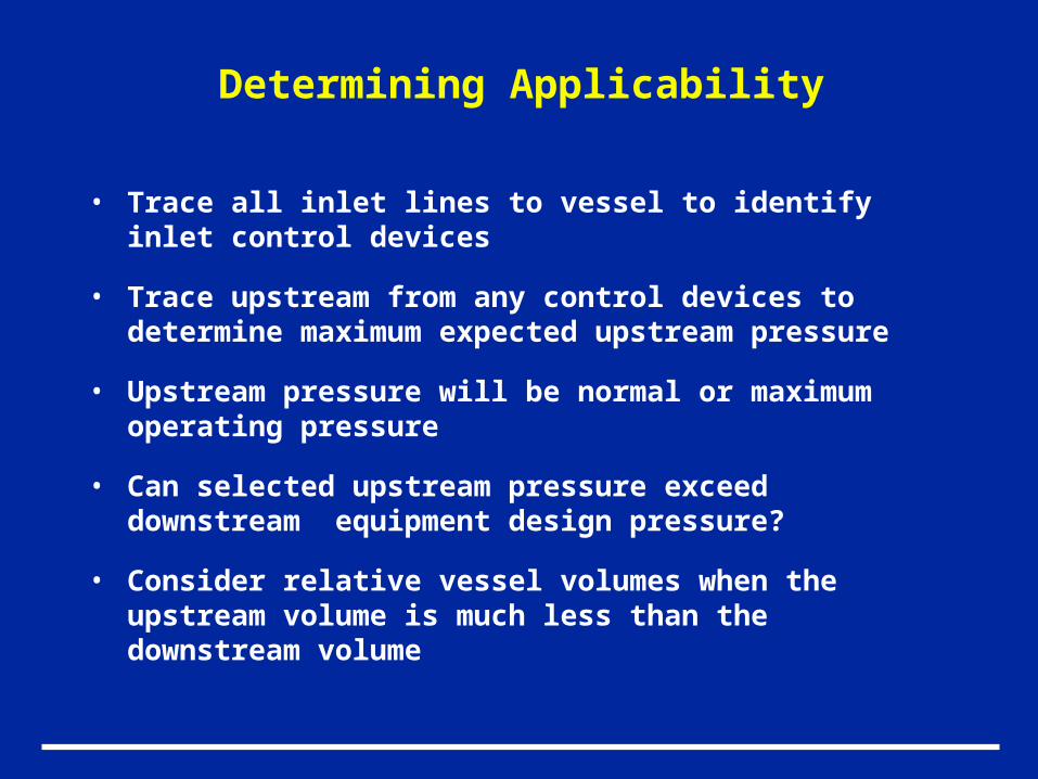
Determining Applicability
• Trace all inlet lines to vessel to identify inlet control devices
• Trace upstream from any control devices to determine maximum expected upstream pressure
• Upstream pressure will be normal or maximum operating pressure
• Can selected upstream pressure exceed downstream equipment design pressure?
• Consider relative vessel volumes when the upstream volume is much less than the downstream volume
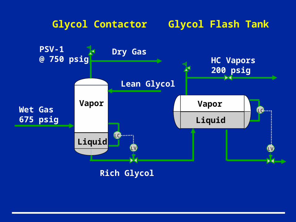
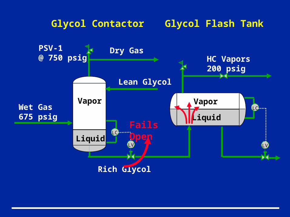
Liquid
Vapor
PSV-1@ 750 psig
Wet Gas675 psig
Lean Glycol
Rich Glycol
Dry Gas
Glycol Contactor
LC
LV
HC Vapors200 psig
LC
LV
Glycol Flash Tank
Liquid
Vapor
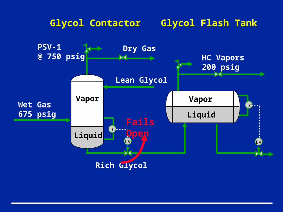
Liquid
Vapor
PSV-1@ 750 psig
Wet Gas675 psig
Lean Glycol
Rich Glycol
Dry Gas
Glycol Contactor
LC
LV
HC Vapors200 psig
LC
LV
Glycol Flash Tank
Liquid
Vapor
Fails Open
Liquid
Vapor
PSV-1@ 750 psig
Wet Gas675 psig
Lean Glycol
Rich Glycol
Dry Gas
Glycol Contactor
LC
LV
HC Vapors200 psig
LC
LV
Glycol Flash Tank
Liquid
Vapor
Fails Open
API RP 521 Section 3.10.3
“The scenario to consider is that one inlet valve will be in a fully opened position regardless of the control valve failure position…. Therefore, the required relief capacity is the difference between the maximum expected inlet flow and the normal outlet flow adjusted for relieving conditions and considering unit turndown…”
Determining Required Relief Rate
• Use control valve manufacturer’s calculations
• Determine valve flow coefficients
• Consider partially or fully open bypass
• Calculate flow across control valve at downstream relief pressure
• Take credit for normal outflow in volumetric terms
Gas Blowby – Special Considerations
Potential for Two Phase Relief in Downstream Vessel
• Perform relative inventory check to determine how much downstream vessel will fill
• Assume downstream level control remains in normal position
Relief behavior depends on liquid level
- Below inlet nozzle all vapor relief
- Between inlet nozzle and full, perform disengagement calculation vapor or two phase
- Full liquid displacement equal to volume of incoming vapor
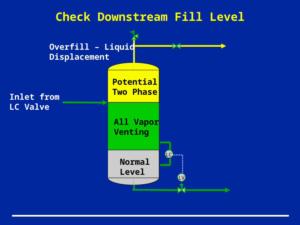
Check Downstream Fill Level
NormalLevel
Vapor
LC
LV
All VaporVenting
PotentialTwo Phase
Inlet fromLC Valve
Overfill – LiquidDisplacement
Gas Blowby – Special Considerations
Calculating Flow Across Level Control Valve
• Consider assuming two phase flow across valve to reduce relief requirement
Heat ExchangerTube Rupture
Causes:
- Vibration, corrosion, erosion, thermal shock, differential shell side to tube side expansion (fixed tube sheet exchanger), brittle fracture potential, tube to baffle chafing, degradation of tubes and tube sheets.
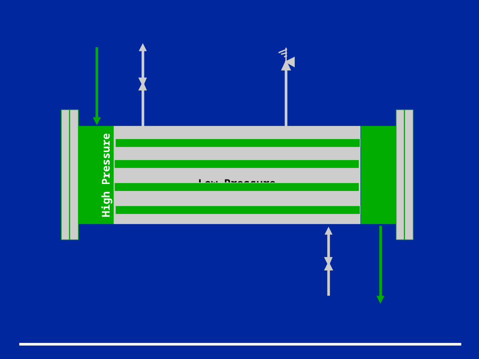
Low Pressure
Hig
h P
ress
ure
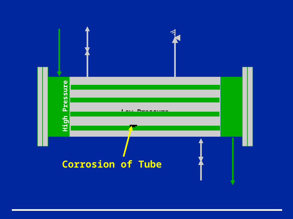
Corrosion of Tube
Low Pressure
Hig
h P
ress
ure
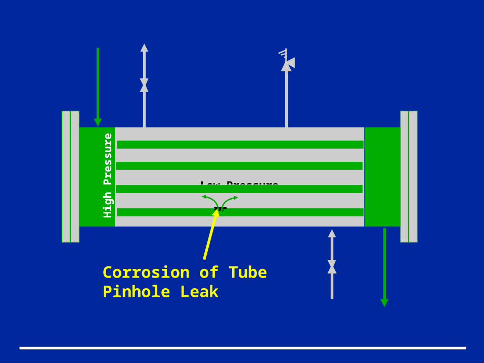
Corrosion of TubePinhole Leak
Low Pressure
Hig
h P
ress
ure
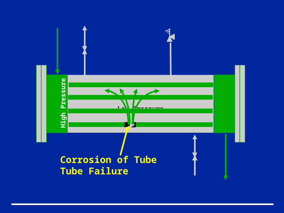
Corrosion of TubeTube Failure
Low Pressure
Hig
h P
ress
ure
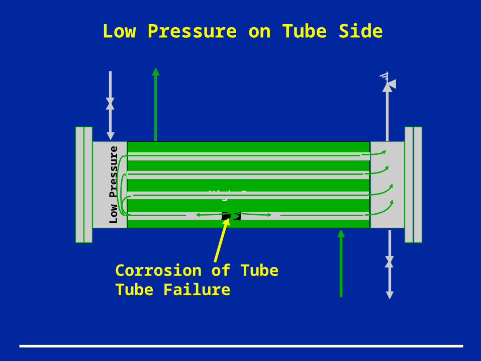
Corrosion of TubeTube Failure
High Pressure
Lo
w P
ress
ure
Low Pressure on Tube Side
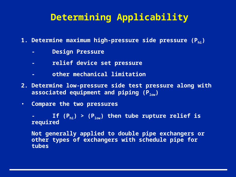
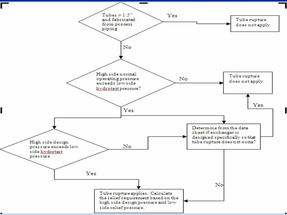
Determining Applicability
1. Determine maximum high-pressure side pressure (Phi)
- Design Pressure
- relief device set pressure
- other mechanical limitation
2. Determine low-pressure side test pressure along with associated equipment and piping (Plow)
• Compare the two pressures
- If (Phi) > (Plow) then tube rupture relief is required
Not generally applied to double pipe exchangers or other types of exchangers with schedule pipe for tubes
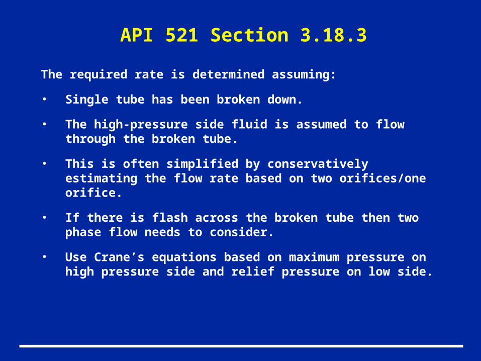
API 521 Section 3.18.3
The required rate is determined assuming:
• Single tube has been broken down.
• The high-pressure side fluid is assumed to flow through the broken tube.
• This is often simplified by conservatively estimating the flow rate based on two orifices/one orifice.
• If there is flash across the broken tube then two phase flow needs to consider.
• Use Crane’s equations based on maximum pressure on high pressure side and relief pressure on low side.
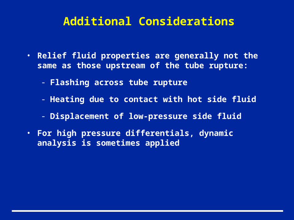
Additional Considerations
• Relief fluid properties are generally not the same as those upstream of the tube rupture:
- Flashing across tube rupture
- Heating due to contact with hot side fluid
- Displacement of low-pressure side fluid
• For high pressure differentials, dynamic analysis is sometimes applied
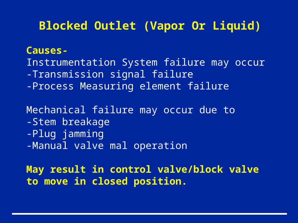
Blocked Outlet (Vapor Or Liquid)
Causes-Instrumentation System failure may occur -Transmission signal failure-Process Measuring element failure
Mechanical failure may occur due to-Stem breakage-Plug jamming-Manual valve mal operation
May result in control valve/block valve to move in closed position.
Determining Applicability For Blocked Vapor
• Identify potential mechanism resulting in blockage
• Identify sources of overpressure include compressors, high-pressure supply headers, and process heat
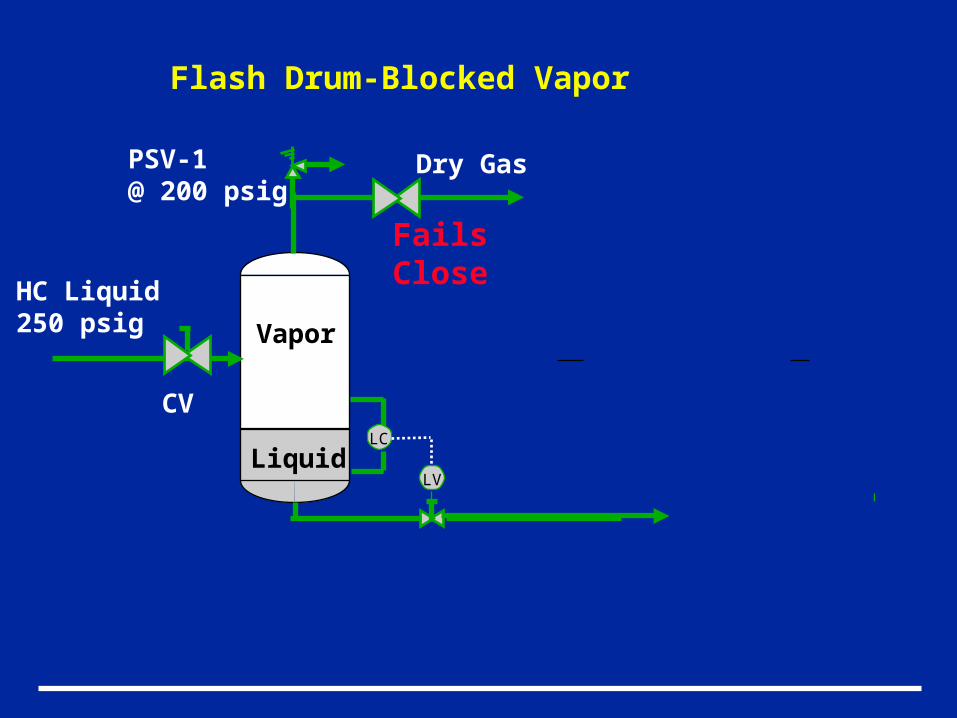
Liquid
Vapor
PSV-1@ 200 psig
Dry Gas
Flash Drum-Blocked Vapor
LC
LV
HC Liquid250 psig
Fails Close
CV
Determining Applicability For Blocked Liquid
• Identify potential mechanism resulting in blockage
• Identify sources of overpressure include pumps, high-pressure supply headers.
• Adequate indication and response time may render overfilling not credible
- Independent high level alarm
- 20 minutes of retention after alarm prior to overfill
• Often not considered for columns and vessels with no normal liquid inflow (suction scrubbers, etc.)
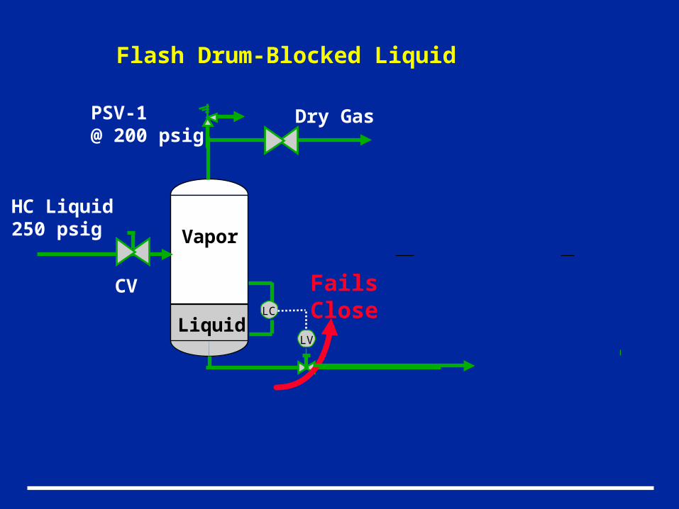
Liquid
Vapor
PSV-1@ 200 psig
Dry Gas
Flash Drum-Blocked Liquid
LC
LV
Fails Close
HC Liquid250 psig
CV
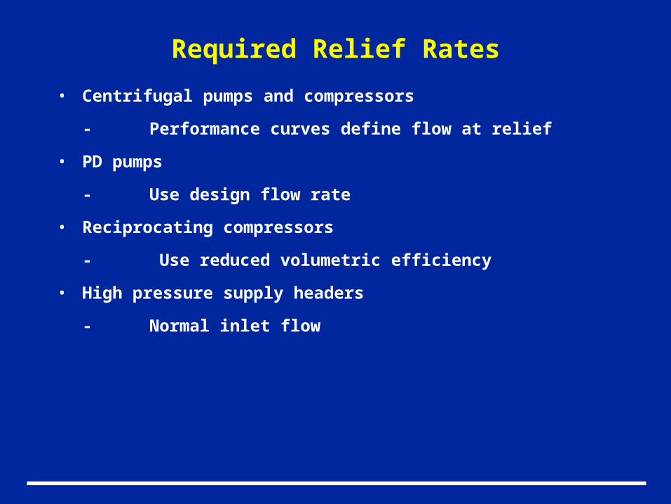
Required Relief Rates
• Centrifugal pumps and compressors
- Performance curves define flow at relief
• PD pumps
- Use design flow rate
• Reciprocating compressors
- Use reduced volumetric efficiency
• High pressure supply headers
- Normal inlet flow
Thermal Expansion
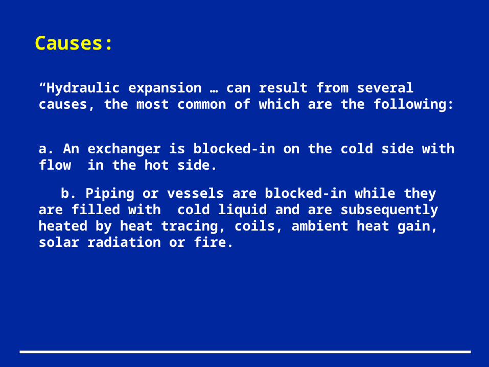
Causes:
“Hydraulic expansion … can result from several causes, the most common of which are the following:
a. An exchanger is blocked-in on the cold side with flow in the hot side.
b. Piping or vessels are blocked-in while they are filled with cold liquid and are subsequently heated by heat tracing, coils, ambient heat gain, solar radiation or fire.
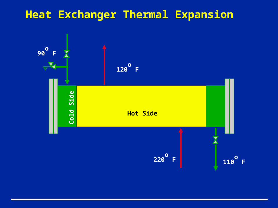
Hot Side
Co
ld S
ide
90o
F
110o
F220o
F
120o
F
Heat Exchanger Thermal Expansion
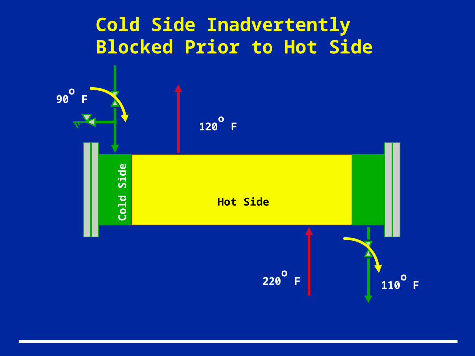
Hot Side
Co
ld S
ide
90o
F
110o
F220o
F
120o
F
Cold Side InadvertentlyBlocked Prior to Hot Side
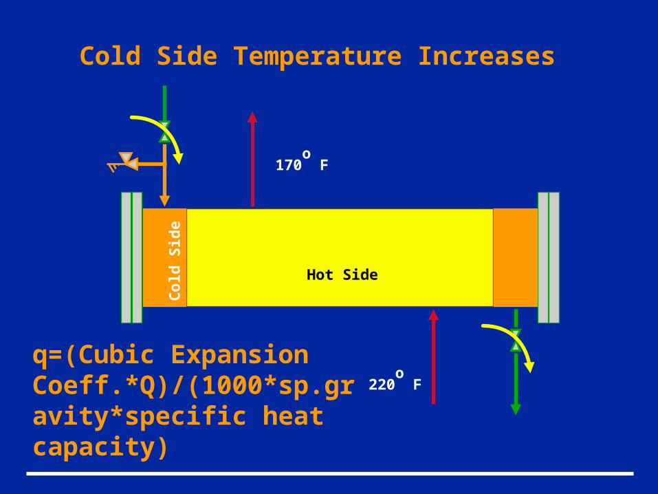
Hot Side
Co
ld S
ide
220o
F
Cold Side Temperature Increases
170o
F
q=(Cubic Expansion Coeff.*Q)/(1000*sp.gravity*specific heat capacity)
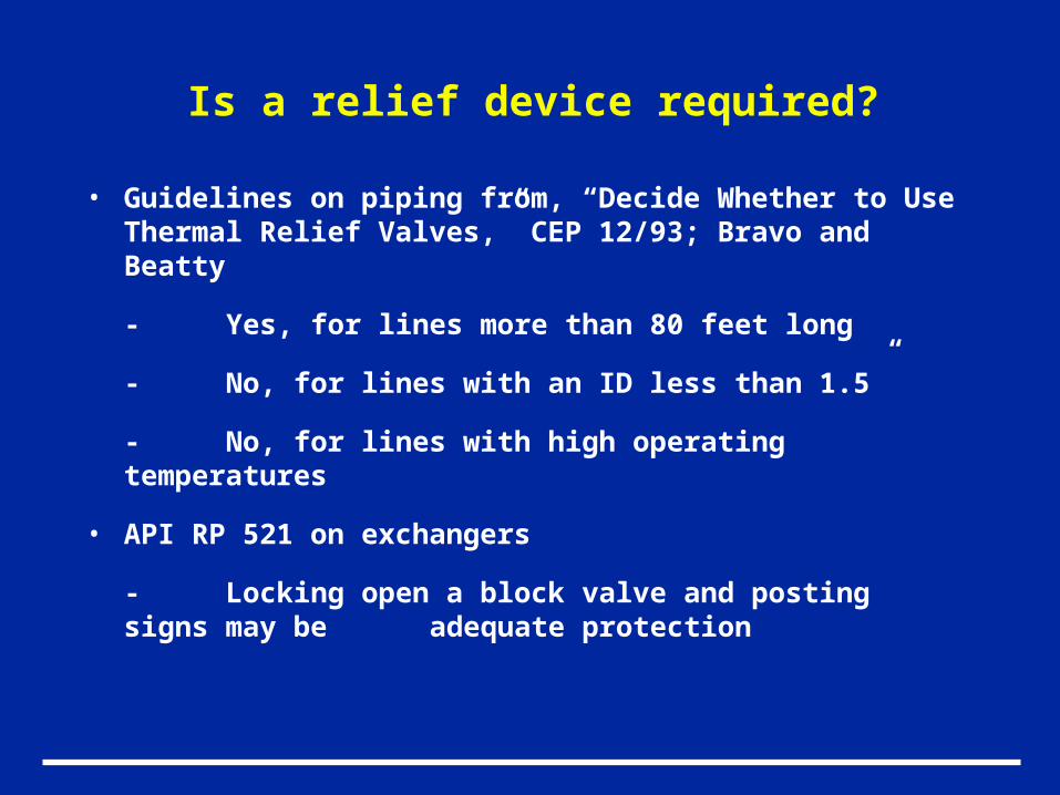
Is a relief device required?
• Guidelines on piping from, “Decide Whether to Use Thermal Relief Valves,” CEP 12/93; Bravo and Beatty
- Yes, for lines more than 80 feet long
- No, for lines with an ID less than 1.5”
- No, for lines with high operating temperatures
• API RP 521 on exchangers
- Locking open a block valve and posting signs may be adequate protection
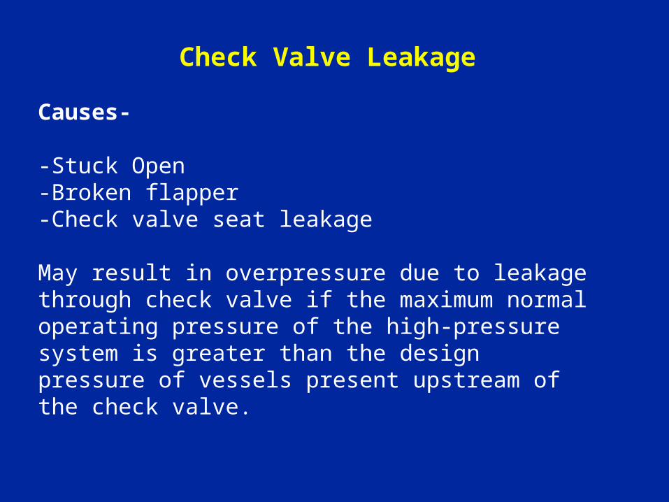
Causes-
-Stuck Open-Broken flapper-Check valve seat leakage
May result in overpressure due to leakage through check valve if the maximum normal operating pressure of the high-pressure system is greater than the design pressure of vessels present upstream of the check valve.
Check Valve Leakage
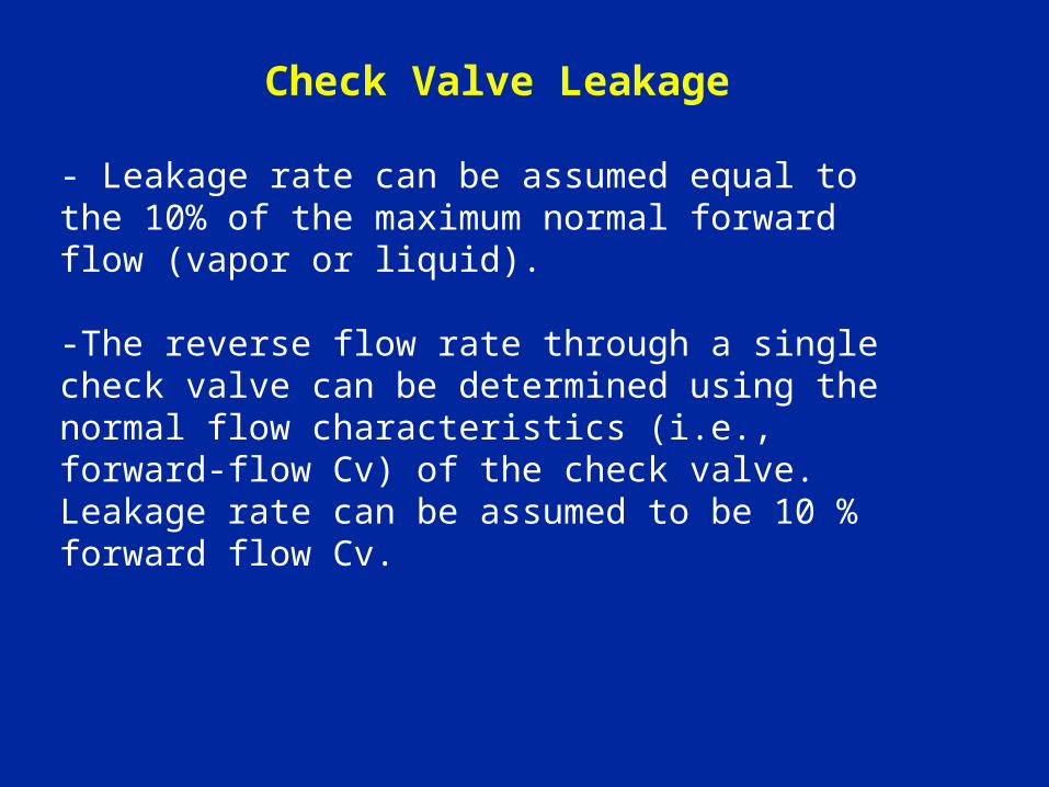
- Leakage rate can be assumed equal to the 10% of the maximum normal forward flow (vapor or liquid).
-The reverse flow rate through a single check valve can be determined using the normal flow characteristics (i.e., forward-flow Cv) of the check valve. Leakage rate can be assumed to be 10 % forward flow Cv.
Check Valve Leakage
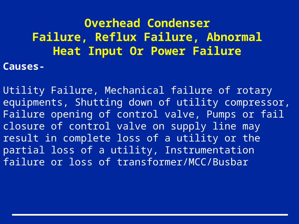
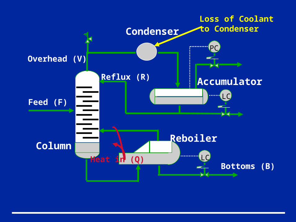
Overhead CondenserFailure, Reflux Failure, Abnormal Heat Input
Or Power FailureCauses-
Utility Failure, Mechanical failure of rotary equipments, Shutting down of utility compressor, Failure opening of control valve, Pumps or fail closure of control valve on supply line may result in complete loss of a utility or the partial loss of a utility, Instrumentation failure or loss of transformer/MCC/Busbar
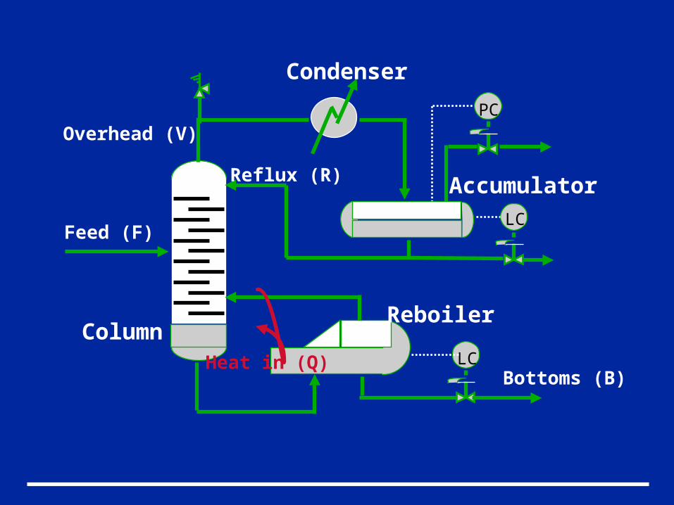
PC
LC
Feed (F)
Heat in (Q)
Overhead (V)
Bottoms (B)
Reflux (R)
Column
Condenser
Accumulator
Reboiler
LC
PC
LC
Feed (F)
Heat in (Q)
Overhead (V)
Bottoms (B)
Reflux (R)
Column
Condenser
Accumulator
Reboiler
LC
Loss of Coolantto Condenser
PC
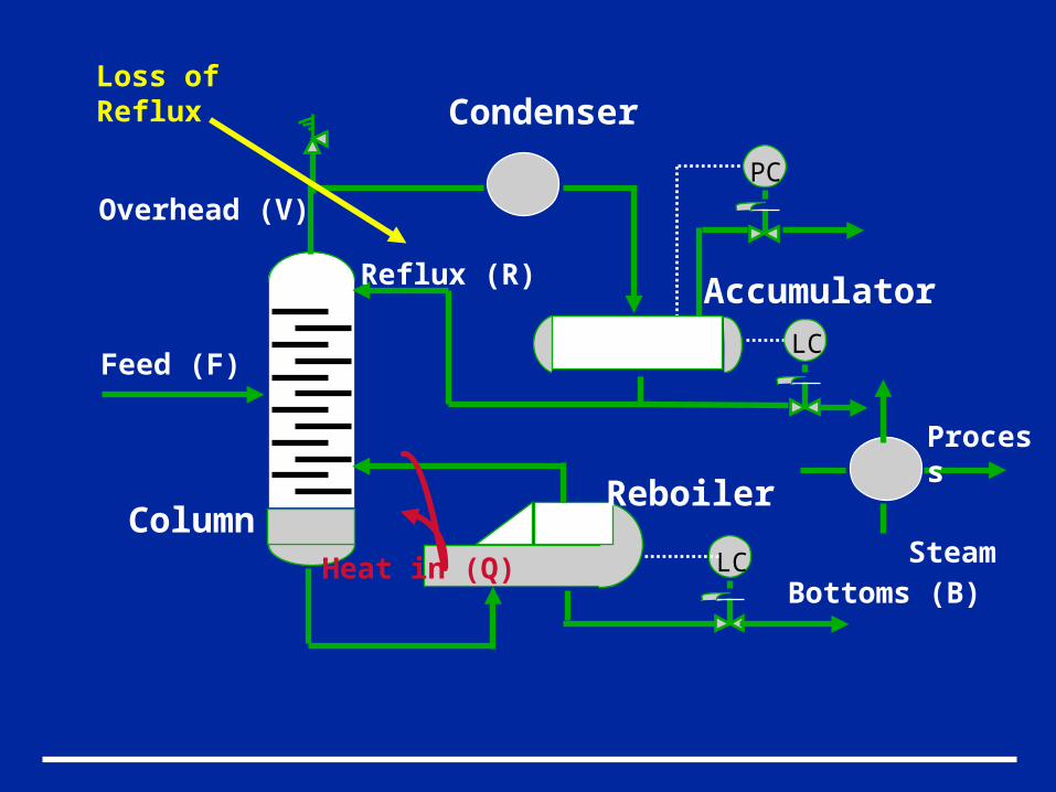
PC
LC
Feed (F)
Heat in (Q)
Overhead (V)
Bottoms (B)
Reflux (R)
Column
Condenser
Accumulator
Reboiler
LC
Loss ofReflux
Steam
Process
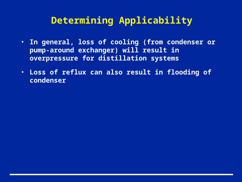
Determining Applicability
• In general, loss of cooling (from condenser or pump-around exchanger) will result in overpressure for distillation systems
• Loss of reflux can also result in flooding of condenser
In Conclusion…
• Collect information required to perform analysis
• Review relevant guidelines
• Determine all overpressure scenarios that apply to each piece of equipment
• Analyze required relief rates using standard methods
• Be conservative at first

Thank You