Embed Size (px)
Citation preview
Overview of Cisco 2800 Series Routers
The Cisco 2800 series of integrated services routers offers secure, wire-speed delivery of concurrent data, voice, and video services. The modular design of the Cisco 2800 series routers provides maximum flexibility, allowing you to configure your router to meet evolving needs. The Cisco 2800 series routers incorporate data, security, and voice services in a single system for fast, scalable delivery of crucial business applications. The routers offer features such as hardware-based VPN encryption acceleration, intrusion-protection and firewall functions, and optional integrated call processing and voice mail. The routers offer a wide variety of network modules and interfaces, voice digital signal processor (DSP) slots, high-density interfaces for a wide range of connectivity requirements, and sufficient performance and slot density for future network expansion requirements and advanced applications.
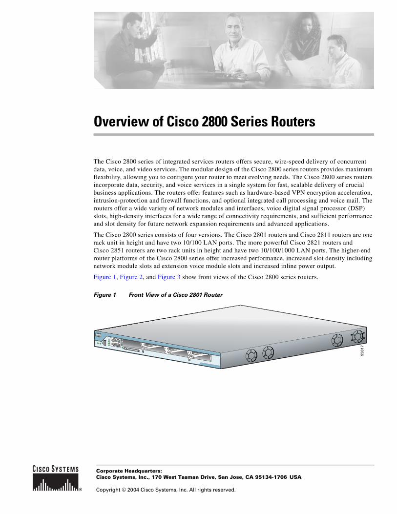
The Cisco 2800 series consists of four versions. The Cisco 2801 routers and Cisco 2811 routers are one rack unit in height and have two 10/100 LAN ports. The more powerful Cisco 2821 routers and Cisco 2851 routers are two rack units in height and have two 10/100/1000 LAN ports. The higher-end router platforms of the Cisco 2800 series offer increased performance, increased slot density including network module slots ad extension voice module slots and increased inline power output.
Figure 1, Figure 2, and Figure 3 show front views of the Cisco 2800 series routers.
Figure 1 Front View of a Cisco 2801 Router
9581
7
Corporate Headquarters:
Copyright © 2004 Cisco Systems, Inc. All rights reserved.
Cisco Systems, Inc., 170 West Tasman Drive, San Jose, CA 95134-1706 USA
Hardware Features
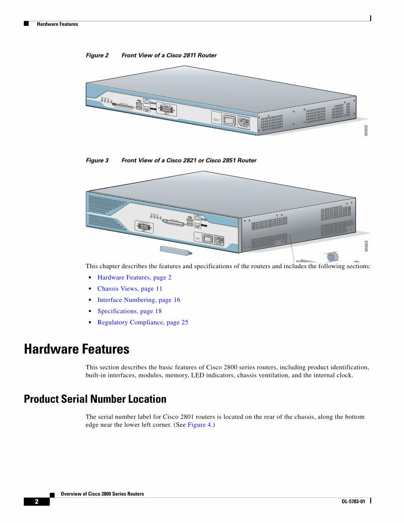
Figure 2 Front View of a Cisco 2811 Router
Figure 3 Front View of a Cisco 2821 or Cisco 2851 Router
This chapter describes the features and specifications of the routers and includes the following sections:
• Hardware Features, page 2
• Chassis Views, page 11
• Interface Numbering, page 16
• Specifications, page 18
• Regulatory Compliance, page 25
Hardware FeaturesThis section describes the basic features of Cisco 2800 series routers, including product identification, built-in interfaces, modules, memory, LED indicators, chassis ventilation, and the internal clock.
Product Serial Number LocationThe serial number label for Cisco 2801 routers is located on the rear of the chassis, along the bottom edge near the lower left corner. (See Figure 4.)
9590
2
Do Not Remove During Network Operation
COMPACT FLASHCONSOLE OPTIONAL RPS INPUT
12V 11A
AUX
SYSPWR
AUX/PWR
SYSACT CF
-48V 4A
100-240 V~ 4A50/60 Hz
0
1
9590
3
Do Not Remove During Network Operation
COMPACT FLASHCONSOLE
AUX
SYSPWR
AUX/PWR
SYSACT CF
0
1
OPTIONAL RPS INPUT
12V 11A-48V 4A
100-240 V~ 4A50/60 Hz
2Overview of Cisco 2800 Series Routers
OL-5783-01
Hardware Features
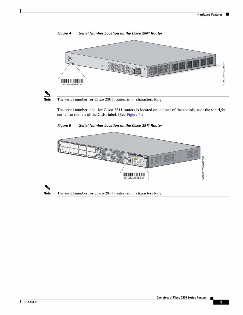
Figure 4 Serial Number Location on the Cisco 2801 Router
Note The serial number for Cisco 2801 routers is 11 characters long.
The serial number label for Cisco 2811 routers is located on the rear of the chassis, near the top right corner, to the left of the CLEI label. (See Figure 5.)
Figure 5 Serial Number Location on the Cisco 2811 Router
Note The serial number for Cisco 2811 routers is 11 characters long.
1173
42 7
81-0
0286
-01
SN: AAANNNNXXXX
SN: AAANNNNXXXX
1039
62 7
81-0
0287
-01A= ACT
FE 0/1
PVDM1 PVDM0 AIM1 AIM0
FE 0/0
S= SPEEDA= FDXA= LINK
A
F
S
L
A
F
S
L
SLOT2
SLOT0
SLOT3
SLOT1
ENM0
SN: AAANNNNXXXX
3Overview of Cisco 2800 Series Routers
OL-5783-01
Hardware Features
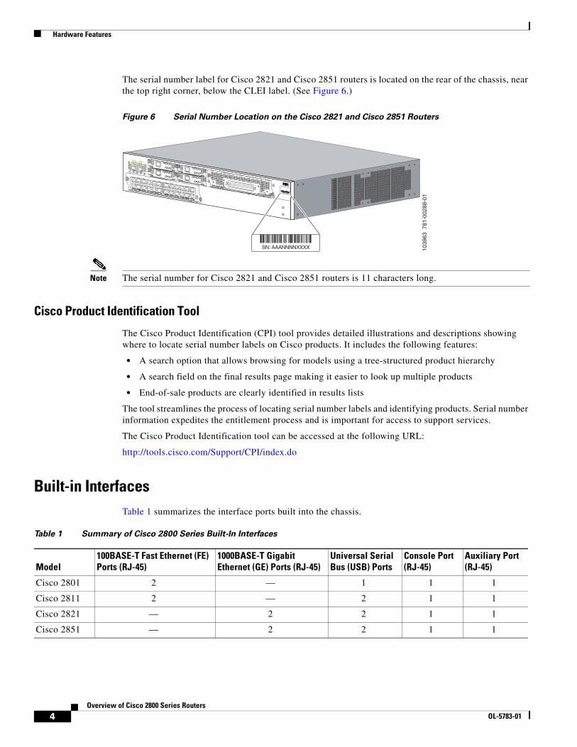
The serial number label for Cisco 2821 and Cisco 2851 routers is located on the rear of the chassis, near the top right corner, below the CLEI label. (See Figure 6.)
Figure 6 Serial Number Location on the Cisco 2821 and Cisco 2851 Routers
Note The serial number for Cisco 2821 and Cisco 2851 routers is 11 characters long.
Cisco Product Identification Tool
The Cisco Product Identification (CPI) tool provides detailed illustrations and descriptions showing where to locate serial number labels on Cisco products. It includes the following features:
• A search option that allows browsing for models using a tree-structured product hierarchy
• A search field on the final results page making it easier to look up multiple products
• End-of-sale products are clearly identified in results lists
The tool streamlines the process of locating serial number labels and identifying products. Serial number information expedites the entitlement process and is important for access to support services.
The Cisco Product Identification tool can be accessed at the following URL:
http://tools.cisco.com/Support/CPI/index.do
Built-in InterfacesTable 1 summarizes the interface ports built into the chassis.
1039
63 7
81-0
0288
-01
A= ACT
FE 0/1
PVDM2 PVDM1 PVDM0 AIM1 AIM0
FE 0/0
S= SPEEDA= FDXA= LINK
A
F
S
L
A
F
S
L
SN: AAANNNNXXXX
SN: AAANNNNXXXX
Table 1 Summary of Cisco 2800 Series Built-In Interfaces
Model100BASE-T Fast Ethernet (FE) Ports (RJ-45)
1000BASE-T Gigabit Ethernet (GE) Ports (RJ-45)
Universal Serial Bus (USB) Ports
Console Port (RJ-45)
Auxiliary Port (RJ-45)
Cisco 2801 2 — 1 1 1
Cisco 2811 2 — 2 1 1
Cisco 2821 — 2 2 1 1
Cisco 2851 — 2 2 1 1
4Overview of Cisco 2800 Series Routers
OL-5783-01
Hardware Features
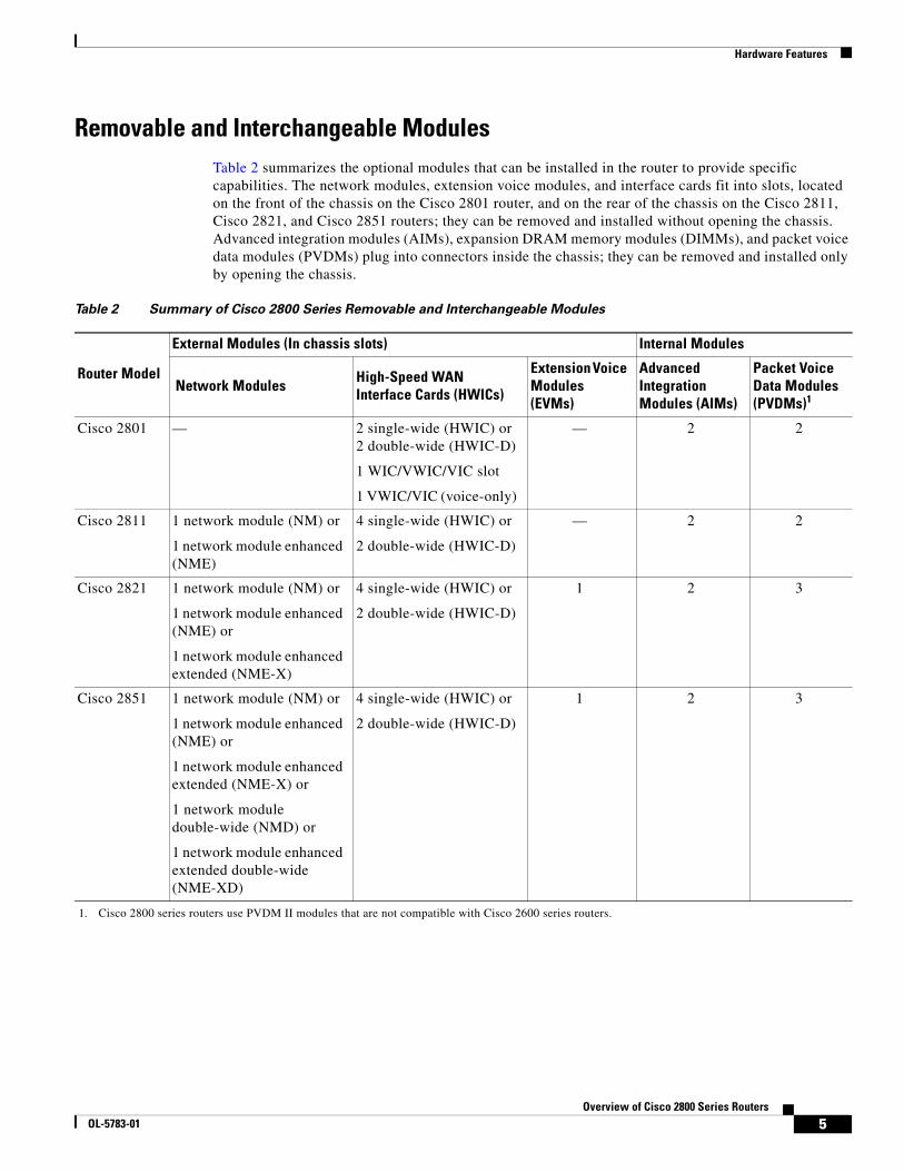
Removable and Interchangeable ModulesTable 2 summarizes the optional modules that can be installed in the router to provide specific capabilities. The network modules, extension voice modules, and interface cards fit into slots, located on the front of the chassis on the Cisco 2801 router, and on the rear of the chassis on the Cisco 2811, Cisco 2821, and Cisco 2851 routers; they can be removed and installed without opening the chassis. Advanced integration modules (AIMs), expansion DRAM memory modules (DIMMs), and packet voice data modules (PVDMs) plug into connectors inside the chassis; they can be removed and installed only by opening the chassis.
Table 2 Summary of Cisco 2800 Series Removable and Interchangeable Modules
Router Model
External Modules (In chassis slots) Internal Modules
Network Modules High-Speed WAN Interface Cards (HWICs)
Extension Voice Modules (EVMs)
Advanced Integration Modules (AIMs)
Packet Voice Data Modules (PVDMs)1
1. Cisco 2800 series routers use PVDM II modules that are not compatible with Cisco 2600 series routers.
Cisco 2801 — 2 single-wide (HWIC) or 2 double-wide (HWIC-D)
1 WIC/VWIC/VIC slot
1 VWIC/VIC (voice-only)
— 2 2
Cisco 2811 1 network module (NM) or
1 network module enhanced (NME)
4 single-wide (HWIC) or
2 double-wide (HWIC-D)
— 2 2
Cisco 2821 1 network module (NM) or
1 network module enhanced (NME) or
1 network module enhanced extended (NME-X)
4 single-wide (HWIC) or
2 double-wide (HWIC-D)
1 2 3
Cisco 2851 1 network module (NM) or
1 network module enhanced (NME) or
1 network module enhanced extended (NME-X) or
1 network module double-wide (NMD) or
1 network module enhanced extended double-wide (NME-XD)
4 single-wide (HWIC) or
2 double-wide (HWIC-D)
1 2 3
5Overview of Cisco 2800 Series Routers
OL-5783-01
Hardware Features
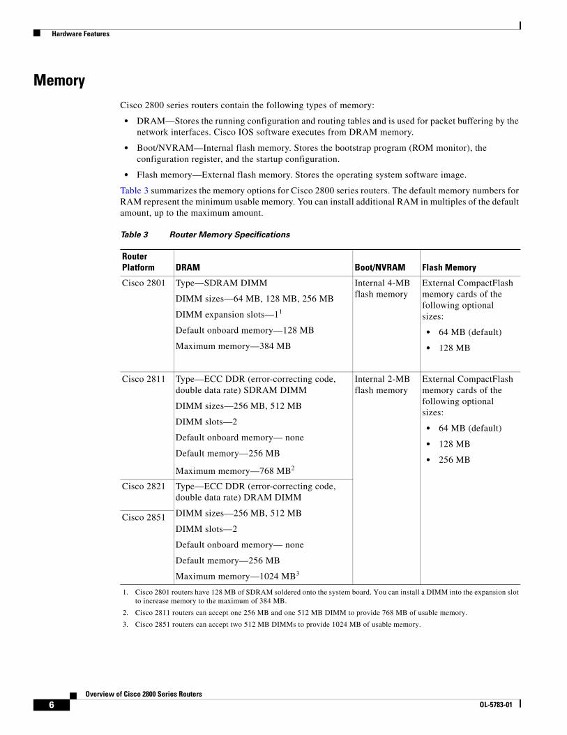
MemoryCisco 2800 series routers contain the following types of memory:
• DRAM—Stores the running configuration and routing tables and is used for packet buffering by the network interfaces. Cisco IOS software executes from DRAM memory.
• Boot/NVRAM—Internal flash memory. Stores the bootstrap program (ROM monitor), the configuration register, and the startup configuration.
• Flash memory—External flash memory. Stores the operating system software image.
Table 3 summarizes the memory options for Cisco 2800 series routers. The default memory numbers for RAM represent the minimum usable memory. You can install additional RAM in multiples of the default amount, up to the maximum amount.
Table 3 Router Memory Specifications
Router Platform DRAM Boot/NVRAM Flash Memory
Cisco 2801 Type—SDRAM DIMM
DIMM sizes—64 MB, 128 MB, 256 MB
DIMM expansion slots—11
Default onboard memory—128 MB
Maximum memory—384 MB
1. Cisco 2801 routers have 128 MB of SDRAM soldered onto the system board. You can install a DIMM into the expansion slot to increase memory to the maximum of 384 MB.
Internal 4-MB flash memory
External CompactFlash memory cards of the following optional sizes:
• 64 MB (default)
• 128 MB
Cisco 2811 Type—ECC DDR (error-correcting code, double data rate) SDRAM DIMM
DIMM sizes—256 MB, 512 MB
DIMM slots—2
Default onboard memory— none
Default memory—256 MB
Maximum memory—768 MB2
2. Cisco 2811 routers can accept one 256 MB and one 512 MB DIMM to provide 768 MB of usable memory.
Internal 2-MB flash memory
External CompactFlash memory cards of the following optional sizes:
• 64 MB (default)
• 128 MB
• 256 MB
Cisco 2821 Type—ECC DDR (error-correcting code, double data rate) DRAM DIMM
DIMM sizes—256 MB, 512 MB
DIMM slots—2
Default onboard memory— none
Default memory—256 MB
Maximum memory—1024 MB3
3. Cisco 2851 routers can accept two 512 MB DIMMs to provide 1024 MB of usable memory.
Cisco 2851
6Overview of Cisco 2800 Series Routers
OL-5783-01
Hardware Features
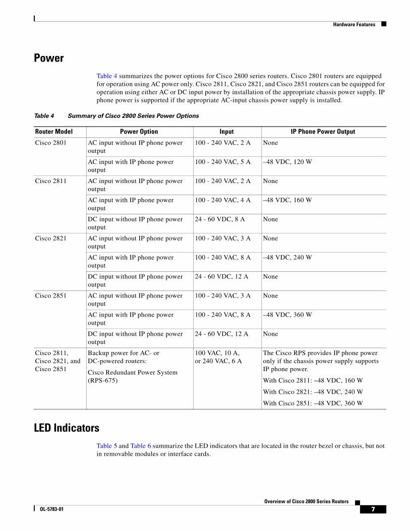
PowerTable 4 summarizes the power options for Cisco 2800 series routers. Cisco 2801 routers are equipped for operation using AC power only. Cisco 2811, Cisco 2821, and Cisco 2851 routers can be equipped for operation using either AC or DC input power by installation of the appropriate chassis power supply. IP phone power is supported if the appropriate AC-input chassis power supply is installed.
LED IndicatorsTable 5 and Table 6 summarize the LED indicators that are located in the router bezel or chassis, but not in removable modules or interface cards.
Table 4 Summary of Cisco 2800 Series Power Options
Router Model Power Option Input IP Phone Power Output
Cisco 2801 AC input without IP phone power output
100 - 240 VAC, 2 A None
AC input with IP phone power output
100 - 240 VAC, 5 A –48 VDC, 120 W
Cisco 2811 AC input without IP phone power output
100 - 240 VAC, 2 A None
AC input with IP phone power output
100 - 240 VAC, 4 A –48 VDC, 160 W
DC input without IP phone power output
24 - 60 VDC, 8 A None
Cisco 2821 AC input without IP phone power output
100 - 240 VAC, 3 A None
AC input with IP phone power output
100 - 240 VAC, 8 A –48 VDC, 240 W
DC input without IP phone power output
24 - 60 VDC, 12 A None
Cisco 2851 AC input without IP phone power output
100 - 240 VAC, 3 A None
AC input with IP phone power output
100 - 240 VAC, 8 A –48 VDC, 360 W
DC input without IP phone power output
24 - 60 VDC, 12 A None
Cisco 2811, Cisco 2821, and Cisco 2851
Backup power for AC- or DC-powered routers:
Cisco Redundant Power System (RPS-675)
100 VAC, 10 A, or 240 VAC, 6 A
The Cisco RPS provides IP phone power only if the chassis power supply supports IP phone power.
With Cisco 2811: –48 VDC, 160 W
With Cisco 2821: –48 VDC, 240 W
With Cisco 2851: –48 VDC, 360 W
7Overview of Cisco 2800 Series Routers
OL-5783-01
Hardware Features
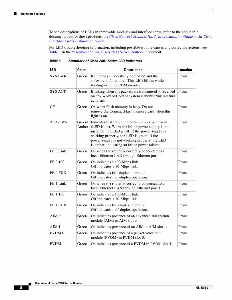
To see descriptions of LEDs in removable modules and interface cards, refer to the applicable documentation for those products: the Cisco Network Modules Hardware Installation Guide or the Cisco Interface Cards Installation Guide.
For LED troubleshooting information, including possible trouble causes and corrective actions, see Table 1 in the “Troubleshooting Cisco 2800 Series Routers” document.
Table 5 Summary of Cisco 2801 Series LED Indicators
LED Color Description Location
SYS PWR Green Router has successfully booted up and thesoftware is functional. This LED blinks whilebooting or in the ROM monitor.
Front
SYS ACT Green Blinking when any packets are transmitted or received on any WAN or LAN or system is monitoring internal activities.
Front
CF Green On when flash memory is busy. Do notremove the CompactFlash memory card when this light is on.
Front
AUX/PWR Green/Amber
Indicates that the inline power supply is present(LED is on). When the inline power supply is notinstalled, the LED is off. If the power supply isworking properly, the LED is green. If thepower supply is not working properly, the LEDis amber, indicating an inline power failure.
Front
FE 0 Link Green On when the router is correctly connected to alocal Ethernet LAN through Ethernet port 0.
Front
FE 0 100 Green On indicates a 100-Mbps link. Off indicates a 10-Mbps link.
Front
FE 0 FDX Green On indicates full-duplex operation.Off indicates half-duplex operation.
Front
FE 1 Link Green On when the router is correctly connected to alocal Ethernet LAN through Ethernet port 1.
Front
FE 1 100 Green On indicates a 100-Mbps link. Off indicates a 10-Mbps link.
Front
FE 1 FDX Green On indicates full-duplex operation.Off indicates half-duplex operation.
Front
AIM 0 Green On indicates presence of an advanced integrationmodule (AIM) in AIM slot 0.
Front
AIM 1 Green On indicates presence of an AIM in AIM slot 1. Front
PVDM 0 Green On indicates presence of a packet voice datamodule (PVDM) in PVDM slot 0.
Front
PVDM 1 Green On indicates presence of a PVDM in PVDM slot 1. Front
8Overview of Cisco 2800 Series Routers
OL-5783-01
Hardware Features
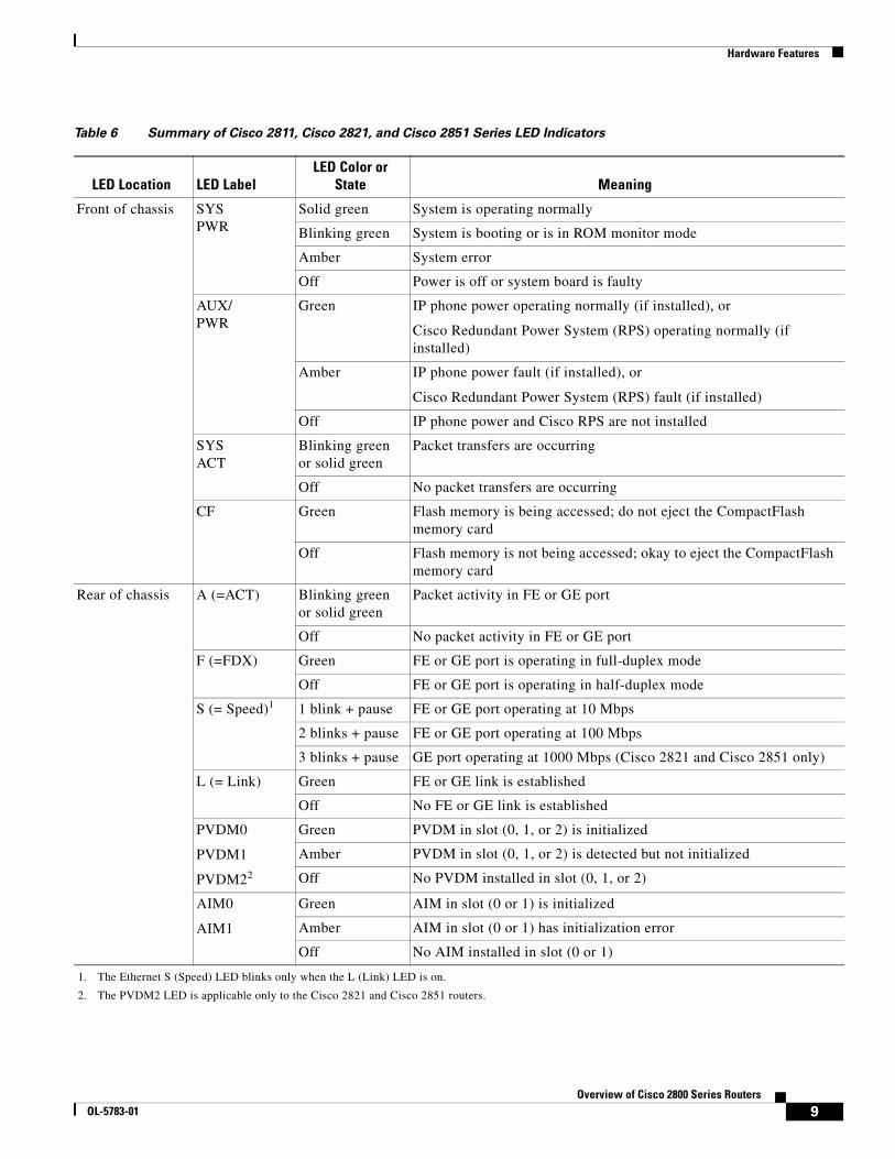
Table 6 Summary of Cisco 2811, Cisco 2821, and Cisco 2851 Series LED Indicators
LED Location LED LabelLED Color or
State Meaning
Front of chassis SYSPWR
Solid green System is operating normally
Blinking green System is booting or is in ROM monitor mode
Amber System error
Off Power is off or system board is faulty
AUX/PWR
Green IP phone power operating normally (if installed), or
Cisco Redundant Power System (RPS) operating normally (if installed)
Amber IP phone power fault (if installed), or
Cisco Redundant Power System (RPS) fault (if installed)
Off IP phone power and Cisco RPS are not installed
SYS ACT
Blinking green or solid green
Packet transfers are occurring
Off No packet transfers are occurring
CF Green Flash memory is being accessed; do not eject the CompactFlash memory card
Off Flash memory is not being accessed; okay to eject the CompactFlash memory card
Rear of chassis A (=ACT) Blinking green or solid green
Packet activity in FE or GE port
Off No packet activity in FE or GE port
F (=FDX) Green FE or GE port is operating in full-duplex mode
Off FE or GE port is operating in half-duplex mode
S (= Speed)1
1. The Ethernet S (Speed) LED blinks only when the L (Link) LED is on.
1 blink + pause FE or GE port operating at 10 Mbps
2 blinks + pause FE or GE port operating at 100 Mbps
3 blinks + pause GE port operating at 1000 Mbps (Cisco 2821 and Cisco 2851 only)
L (= Link) Green FE or GE link is established
Off No FE or GE link is established
PVDM0
PVDM1
PVDM22
2. The PVDM2 LED is applicable only to the Cisco 2821 and Cisco 2851 routers.
Green PVDM in slot (0, 1, or 2) is initialized
Amber PVDM in slot (0, 1, or 2) is detected but not initialized
Off No PVDM installed in slot (0, 1, or 2)
AIM0
AIM1
Green AIM in slot (0 or 1) is initialized
Amber AIM in slot (0 or 1) has initialization error
Off No AIM installed in slot (0 or 1)
9Overview of Cisco 2800 Series Routers
OL-5783-01
Hardware Features
Chassis VentilationInternal multispeed fans provide chassis cooling, controlled by an onboard temperature sensor.
The Cisco 2801 router has two fans. The Cisco 2801 router with inline power includes two additional fans integrated with the inline power supply, for a total of four fans. The Cisco 2801 internal fans operate at three different speeds, running at the slower speeds to conserve power and reduce fan noise at ambient temperatures below 40oC. They operate at the highest speed in ambient temperatures above 40oC.
The Cisco 2811 router has three fans that operate at a slower speed to conserve power and reduce fan noise at ambient temperatures below 32oC. They operate at high speed in ambient temperatures above 32oC.
The Cisco 2821 and Cisco 2851 routers have three fans that operate at a slower speed to conserve power and reduce fan noise at ambient temperatures below 40oC. They operate at high speed in ambient temperatures above 40oC.
Caution Ensure the device is not installed in close proximity to other devices which could lead to excessive pre-heating of air at the air intake of the router.
Caution Your chassis installation must allow unrestricted airflow for chassis cooling.
Cisco 2800 Series Router Installation and Preventive Maintenance
Periodic inspection and cleaning of the external surface of the router is recommended to minimize the negative impact of environmental dust or debris on the router performance. The frequency of inspection and cleaning is dependent upon the severity of the environmental conditions. Cleaning involves vacuuming of router air intake and exhaust vents.
Caution Fans are dynamic Electro-Mechanical devices. As such, fans can fail for various electronic reasons, and will eventually fail due to mechanical wear-out. Sites with ambient temperatures consistently above 25 degree C and with potentially high levels of dust or debris may require fan servicing.
Real-Time ClockAn internal real-time clock with battery backup provides the system software with time of day on system power up. This allows the system to verify the validity of the certification authority (CA) certificate. In the Cisco 2811, Cisco 2821, and Cisco 2851 routers, the clock and battery are permanently installed; the battery lasts the life of the router under the operating environmental conditions specified for the router. The Cisco 2801 router has a socketed lithium battery. This battery lasts the life of the router under the operating environmental conditions specified for the router, and is not field-replaceable.
Note If the lithium battery in a Cisco 2801 router should fail, the router must be returned to Cisco for repair.
Although the battery is not intended to be field-replaceable, the following warning must be heeded:
10Overview of Cisco 2800 Series Routers
OL-5783-01
Chassis Views
Warning There is the danger of explosion if the battery is replaced incorrectly. Replace the battery only with the same or equivalent type recommended by the manufacturer. Dispose of used batteries according to the manufacturer’s instructions. Statement 1015
Chassis ViewsThis section contains views of the front and rear panels of the Cisco 2800 series routers, showing locations of the power and signal interfaces, module slots, status indicators, and chassis identification labels.
Cisco 2801 ChassisFigure 7 shows the front panel of a Cisco 2801 router. Figure 8 shows the back panel.
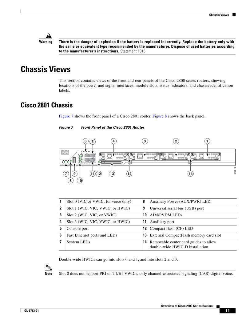
Figure 7 Front Panel of the Cisco 2801 Router
Double-wide HWICs can go into slots 0 and 1, and into slots 2 and 3.
Note Slot 0 does not support PRI on T1/E1 VWICs, only channel-associated signaling (CAS) digital voice.
1 Slot 0 (VIC or VWIC, for voice only) 8 Auxiliary Power (AUX/PWR) LED
2 Slot 1 (WIC, VIC, VWIC, or HWIC) 9 Universal serial bus (USB) port
3 Slot 2 (WIC, VIC, or VWIC) 10 AIM/PVDM LEDs
4 Slot 3 (WIC, VIC, VWIC, or HWIC) 11 Auxiliary port
5 Console port 12 Compact flash (CF) LED
6 Fast Ethernet ports and LEDs 13 External CompactFlash memory card slot
7 System LEDs 14 Removable center card guides to allow double-wide HWIC-D installation
9581
6
123456
7 9 11 12 13 14 14
8 10
11Overview of Cisco 2800 Series Routers
OL-5783-01
Chassis Views
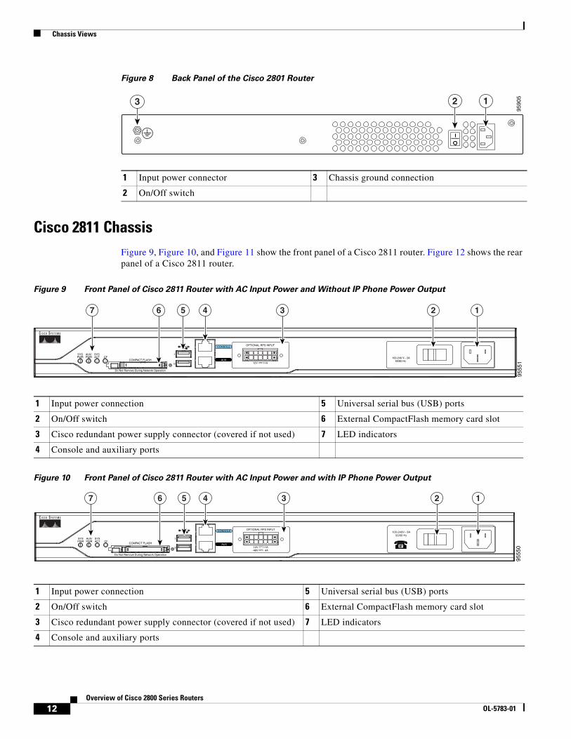
Figure 8 Back Panel of the Cisco 2801 Router
Cisco 2811 ChassisFigure 9, Figure 10, and Figure 11 show the front panel of a Cisco 2811 router. Figure 12 shows the rear panel of a Cisco 2811 router.
Figure 9 Front Panel of Cisco 2811 Router with AC Input Power and Without IP Phone Power Output
Figure 10 Front Panel of Cisco 2811 Router with AC Input Power and with IP Phone Power Output
1 Input power connector 3 Chassis ground connection
2 On/Off switch
9590
5
3 12
1 Input power connection 5 Universal serial bus (USB) ports
2 On/Off switch 6 External CompactFlash memory card slot
3 Cisco redundant power supply connector (covered if not used) 7 LED indicators
4 Console and auxiliary ports
1 Input power connection 5 Universal serial bus (USB) ports
2 On/Off switch 6 External CompactFlash memory card slot
3 Cisco redundant power supply connector (covered if not used) 7 LED indicators
4 Console and auxiliary ports
9555
1
Do Not Remove During Network Operation
COMPACT FLASH
CONSOLE
0
1
OPTIONAL RPS INPUT
12V 11AAUX
SYSPWR
AUX/PWR
SYSACT CF 100-240 V~ 2A
50/60 Hz
124567 3
9555
0
CONSOLEOPTIONAL RPS INPUT
12V 11AAUX
SYSPWR
AUX/PWR
SYSACT CF
-48V 4A
124567 3
0
1
100-240V~ 8A50/60 Hz
Do Not Remove During Network Operation
COMPACT FLASH
12Overview of Cisco 2800 Series Routers
OL-5783-01
Chassis Views
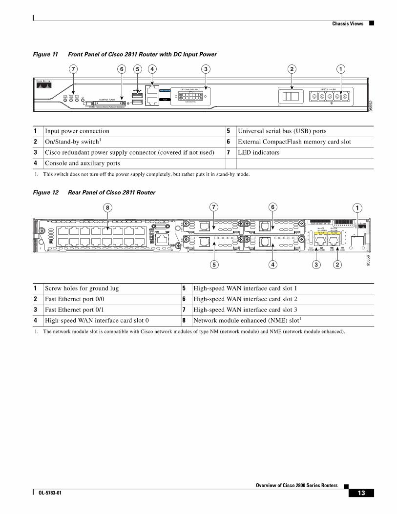
Figure 11 Front Panel of Cisco 2811 Router with DC Input Power
Figure 12 Rear Panel of Cisco 2811 Router
1 Input power connection 5 Universal serial bus (USB) ports
2 On/Stand-by switch1
1. This switch does not turn off the power supply completely, but rather puts it in stand-by mode.
6 External CompactFlash memory card slot
3 Cisco redundant power supply connector (covered if not used) 7 LED indicators
4 Console and auxiliary ports
1 Screw holes for ground lug 5 High-speed WAN interface card slot 1
2 Fast Ethernet port 0/0 6 High-speed WAN interface card slot 2
3 Fast Ethernet port 0/1 7 High-speed WAN interface card slot 3
4 High-speed WAN interface card slot 0 8 Network module enhanced (NME) slot1
1. The network module slot is compatible with Cisco network modules of type NM (network module) and NME (network module enhanced).
9555
2
Do Not Remove During Network Operation
COMPACT FLASH
CONSOLE
0
1
OPTIONAL RPS INPUT
12V 11AAUX
SYSPWR
AUX/PWR
SYSACT CF
4567 3
24-60 V 8A
12
A= ACT
FE 0/1
PVDM1 PVDM0 AIM1 AIM0
FE 0/0S= SPEED
A= FDXA= LINK
A
F
S
L
A
F
S
L
HWIC2
HWIC0
HWIC3
HWIC1
1
23 9555
6
45
67 18
13Overview of Cisco 2800 Series Routers
OL-5783-01
Chassis Views
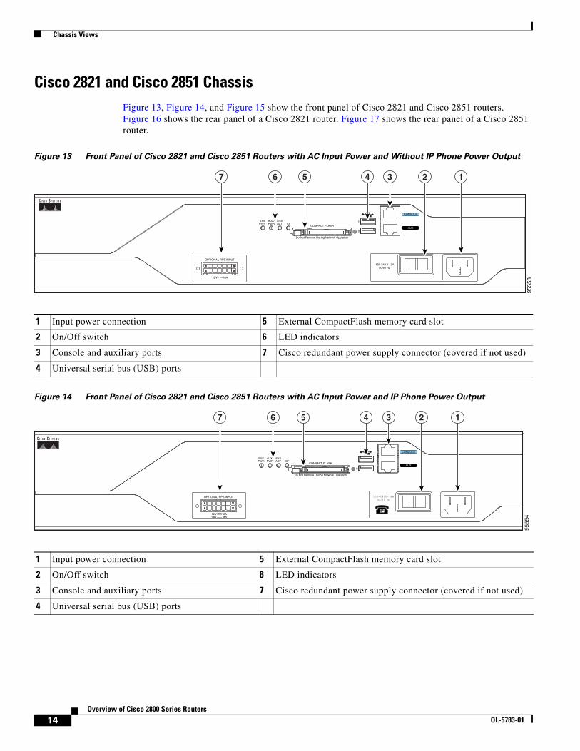
Cisco 2821 and Cisco 2851 ChassisFigure 13, Figure 14, and Figure 15 show the front panel of Cisco 2821 and Cisco 2851 routers. Figure 16 shows the rear panel of a Cisco 2821 router. Figure 17 shows the rear panel of a Cisco 2851 router.
Figure 13 Front Panel of Cisco 2821 and Cisco 2851 Routers with AC Input Power and Without IP Phone Power Output
Figure 14 Front Panel of Cisco 2821 and Cisco 2851 Routers with AC Input Power and IP Phone Power Output
1 Input power connection 5 External CompactFlash memory card slot
2 On/Off switch 6 LED indicators
3 Console and auxiliary ports 7 Cisco redundant power supply connector (covered if not used)
4 Universal serial bus (USB) ports
1 Input power connection 5 External CompactFlash memory card slot
2 On/Off switch 6 LED indicators
3 Console and auxiliary ports 7 Cisco redundant power supply connector (covered if not used)
4 Universal serial bus (USB) ports
9555
3
Do Not Remove During Network Operation
COMPACT FLASH
0
1
OPTIONAL RPS INPUT
SYSPWR
AUX/PWR
SYSACT CF
12V 18A
100-240 V~ 3A50/60 Hz
1457 6 3
CONSOLE
AUX
2
9555
4
Do Not Remove During Network Operation
COMPACT FLASH
0
1
OPTIONAL RPS INPUT
SYSPWR
AUX/PWR
SYSACT CF
12V 18A-48V 8A
1457 6 3
CONSOLE
AUX
2
100-240V~ 8A50/60 Hz
14Overview of Cisco 2800 Series Routers
OL-5783-01
Chassis Views
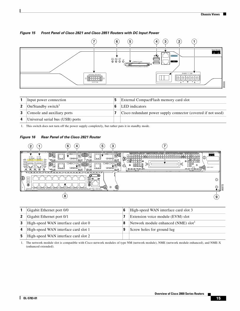
Figure 15 Front Panel of Cisco 2821 and Cisco 2851 Routers with DC Input Power
Figure 16 Rear Panel of the Cisco 2821 Router
1 Input power connection 5 External CompactFlash memory card slot
2 On/Standby switch1
1. This switch does not turn off the power supply completely, but rather puts it in standby mode.
6 LED indicators
3 Console and auxiliary ports 7 Cisco redundant power supply connector (covered if not used)
4 Universal serial bus (USB) ports
1 Gigabit Ethernet port 0/0 6 High-speed WAN interface card slot 3
2 Gigabit Ethernet port 0/1 7 Extension voice module (EVM) slot
3 High-speed WAN interface card slot 0 8 Network module enhanced (NME) slot1
1. The network module slot is compatible with Cisco network modules of type NM (network module), NME (network module enhanced), and NME-X (enhanced extended).
4 High-speed WAN interface card slot 1 9 Screw holes for ground lug
5 High-speed WAN interface card slot 2
9555
5
Do Not Remove During Network Operation
COMPACT FLASH0
_ _+ +A B
1
OPTIONAL RPS INPUT
SYSPWR
AUX/PWR
SYSACT CF
12V 18A
457 6 3
CONSOLE
AUX
24-60V 12A
12
9557
2
12 6 4 3 75
9
A= ACT
GE 0/1
PVDM2 PVDM1 PVDM0 AIM1 AIM0
GE 0/0S= SPEED
A= FDXA= LINK
A
F
S
L
A
F
S
LEVM 2 ONLY
1
8
15Overview of Cisco 2800 Series Routers
OL-5783-01
Interface Numbering
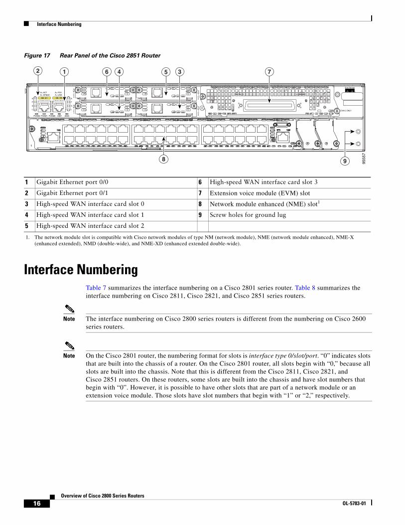
Figure 17 Rear Panel of the Cisco 2851 Router
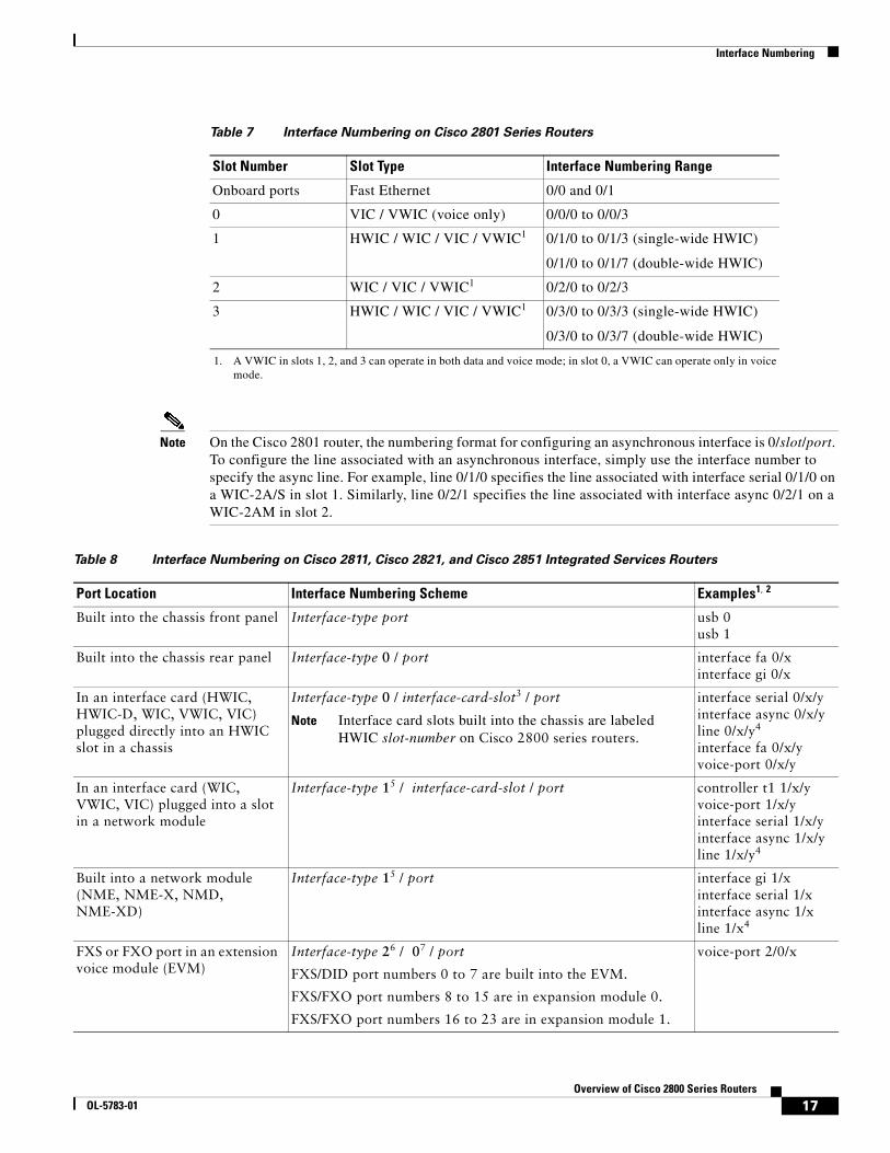
Interface NumberingTable 7 summarizes the interface numbering on a Cisco 2801 series router. Table 8 summarizes the interface numbering on Cisco 2811, Cisco 2821, and Cisco 2851 series routers.
Note The interface numbering on Cisco 2800 series routers is different from the numbering on Cisco 2600 series routers.
Note On the Cisco 2801 router, the numbering format for slots is interface type 0/slot/port. “0” indicates slots that are built into the chassis of a router. On the Cisco 2801 router, all slots begin with “0,” because all slots are built into the chassis. Note that this is different from the Cisco 2811, Cisco 2821, and Cisco 2851 routers. On these routers, some slots are built into the chassis and have slot numbers that begin with “0”. However, it is possible to have other slots that are part of a network module or an extension voice module. Those slots have slot numbers that begin with “1” or “2,” respectively.
1 Gigabit Ethernet port 0/0 6 High-speed WAN interface card slot 3
2 Gigabit Ethernet port 0/1 7 Extension voice module (EVM) slot
3 High-speed WAN interface card slot 0 8 Network module enhanced (NME) slot1
1. The network module slot is compatible with Cisco network modules of type NM (network module), NME (network module enhanced), NME-X (enhanced extended), NMD (double-wide), and NME-XD (enhanced extended double-wide).
4 High-speed WAN interface card slot 1 9 Screw holes for ground lug
5 High-speed WAN interface card slot 2
EVM 2 ONLY
A= ACT
GE 0/1
PVDM2 PVDM1 PVDM0 AIM1 AIM0
GE 0/0
S= SPEEDA= FDXA= LINK
A
F
S
L
A
F
S
L
HWIC2
HWIC0
HWIC3
HWIC1
1
9555
7
7354612
98
16Overview of Cisco 2800 Series Routers
OL-5783-01
Interface Numbering
Note On the Cisco 2801 router, the numbering format for configuring an asynchronous interface is 0/slot/port. To configure the line associated with an asynchronous interface, simply use the interface number to specify the async line. For example, line 0/1/0 specifies the line associated with interface serial 0/1/0 on a WIC-2A/S in slot 1. Similarly, line 0/2/1 specifies the line associated with interface async 0/2/1 on a WIC-2AM in slot 2.
Table 7 Interface Numbering on Cisco 2801 Series Routers
Slot Number Slot Type Interface Numbering Range
Onboard ports Fast Ethernet 0/0 and 0/1
0 VIC / VWIC (voice only) 0/0/0 to 0/0/3
1 HWIC / WIC / VIC / VWIC1
1. A VWIC in slots 1, 2, and 3 can operate in both data and voice mode; in slot 0, a VWIC can operate only in voice mode.
0/1/0 to 0/1/3 (single-wide HWIC)
0/1/0 to 0/1/7 (double-wide HWIC)
2 WIC / VIC / VWIC1 0/2/0 to 0/2/3
3 HWIC / WIC / VIC / VWIC1 0/3/0 to 0/3/3 (single-wide HWIC)
0/3/0 to 0/3/7 (double-wide HWIC)
Table 8 Interface Numbering on Cisco 2811, Cisco 2821, and Cisco 2851 Integrated Services Routers
Port Location Interface Numbering Scheme Examples1, 2
Built into the chassis front panel Interface-type port usb 0usb 1
Built into the chassis rear panel Interface-type 0 / port interface fa 0/xinterface gi 0/x
In an interface card (HWIC, HWIC-D, WIC, VWIC, VIC) plugged directly into an HWIC slot in a chassis
Interface-type 0 / interface-card-slot3 / port
Note Interface card slots built into the chassis are labeled HWIC slot-number on Cisco 2800 series routers.
interface serial 0/x/yinterface async 0/x/yline 0/x/y4
interface fa 0/x/yvoice-port 0/x/y
In an interface card (WIC, VWIC, VIC) plugged into a slot in a network module
Interface-type 15 / interface-card-slot / port controller t1 1/x/yvoice-port 1/x/yinterface serial 1/x/yinterface async 1/x/yline 1/x/y4
Built into a network module (NME, NME-X, NMD, NME-XD)
Interface-type 15 / port interface gi 1/xinterface serial 1/xinterface async 1/xline 1/x4
FXS or FXO port in an extension voice module (EVM)
Interface-type 26 / 07 / port
FXS/DID port numbers 0 to 7 are built into the EVM.
FXS/FXO port numbers 8 to 15 are in expansion module 0.
FXS/FXO port numbers 16 to 23 are in expansion module 1.
voice-port 2/0/x
17Overview of Cisco 2800 Series Routers
OL-5783-01

Specifications
Note On the Cisco 2811, Cisco 2821, and Cisco 2851 routers, the interface numbering scheme is the same for asynchronous interfaces as other types of interfaces. To configure the line associated with an async interface, simply use the interface number to specify the async line. For example, line 0/3/0 specifies the line associated with interface serial 0/3/0 on a WIC-2A/S in slot 3. Similarly, line 1/22 specifies the line associated with interface async 1/22 on a NM-32A in network module slot 1.
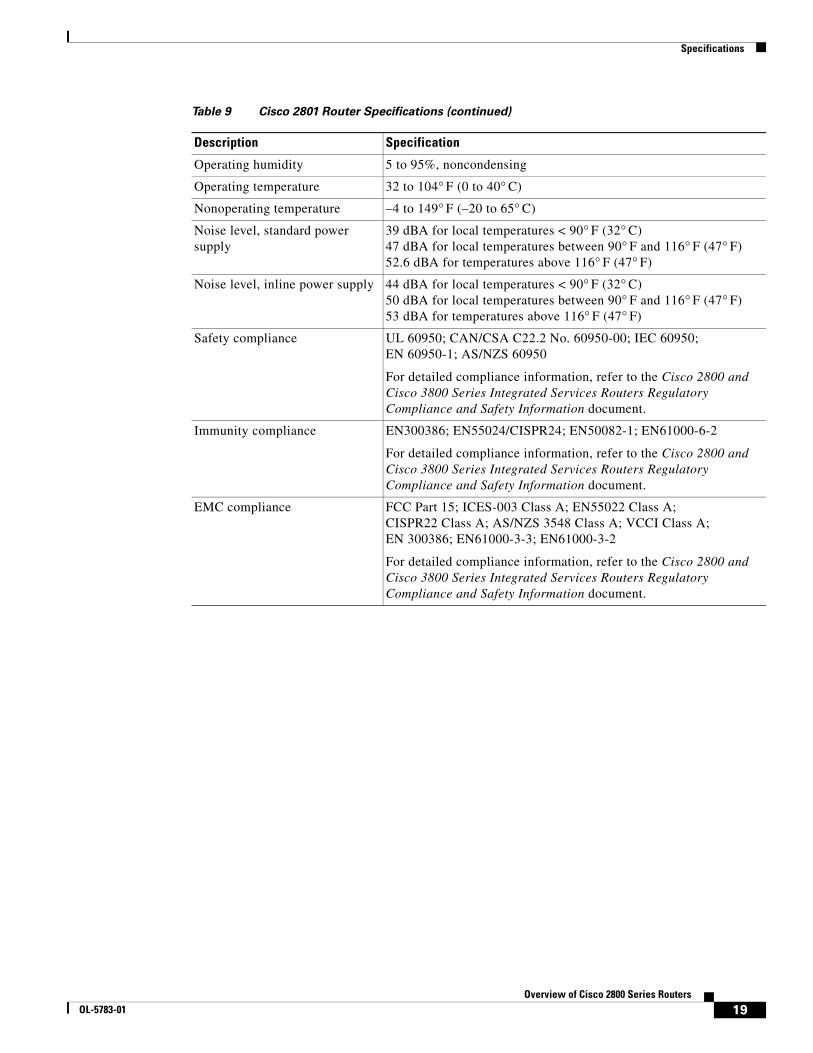
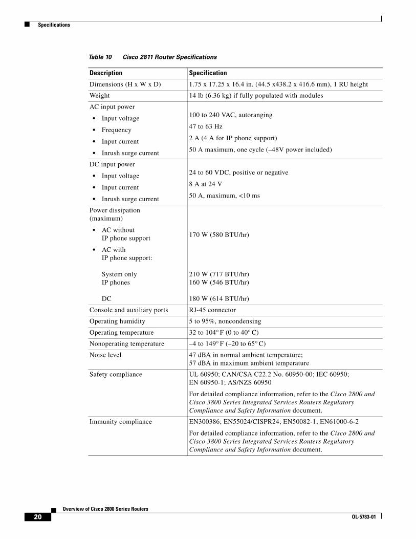
SpecificationsTable 9, Table 10, Table 11, and Table 12 list Cisco 2800 series specifications.
Voice port in a BRI expansion module (internal slot) in an extension voice module (EVM)
Interface-type 26 / 07 / port
Port numbers are 8 to 11 in expansion module 0.
Port numbers are 16 to 19 in expansion module 1.
voice-port 2/0/x
BRI interface in a BRI expansion module (internal slot) in an extension voice module (EVM)
Interface-type 26 / port
Port numbers are 0 to 3 if one expansion module is installed.
Port numbers are 0 to 7 if two expansion modules are installed.
interface bri 2/x
1. Interface abbreviations: fa = Fast Ethernet; gi = Gigabit Ethernet; usb = universal serial bus; bri = ISDN basic rate interface.2. The interfaces listed are examples only; other possible interface types are not listed.3. Interface card slot numbers for double-width (HWIC-D) slots are 1 and 3 only.4. Specify the line number in the Cisco IOS CLI by using the interface number for the associated asynchronous serial interface. 5. “1” is the network module slot number in all Cisco 2800 series routers.6. “2” is the EVM slot number in Cisco 2821 and Cisco 2851 routers.7. “0” is required by the CLI syntax for voice ports in an EVM; it indicates no interface card slots in EVMs.
Table 8 Interface Numbering on Cisco 2811, Cisco 2821, and Cisco 2851 Integrated Services Routers (continued)
Port Location Interface Numbering Scheme Examples1, 2
Table 9 Cisco 2801 Router Specifications
Description Specification
Dimensions (H x W x D) 1.72 x 17.49 x 16.5 in. (4.4 x 44.4 x 41.9 cm).
Weight 10.9 lb (4.9 kg) with standard power supply if fully populated with modules
13.71 lb (6.2 kg) with inline power supply if fully populated with modules
AC input power
• Input voltage
• Frequency
• Input current
• Inrush surge current
100 to 240 VAC, autoranging
47 to 63 Hz
2 A (5 A for IP phone support)
50 A maximum, one cycle (–48V power included)
Power consumption 105 W with standard power supply (maximum)
130 W with inline power supply and 12 IP phones (maximum)
Console and auxiliary ports RJ-45 connector
18Overview of Cisco 2800 Series Routers
OL-5783-01
Specifications
Operating humidity 5 to 95%, noncondensing
Operating temperature 32 to 104° F (0 to 40° C)
Nonoperating temperature –4 to 149° F (–20 to 65° C)
Noise level, standard power supply
39 dBA for local temperatures < 90° F (32° C)47 dBA for local temperatures between 90° F and 116° F (47° F)52.6 dBA for temperatures above 116° F (47° F)
Noise level, inline power supply 44 dBA for local temperatures < 90° F (32° C)50 dBA for local temperatures between 90° F and 116° F (47° F)53 dBA for temperatures above 116° F (47° F)
Safety compliance UL 60950; CAN/CSA C22.2 No. 60950-00; IEC 60950; EN 60950-1; AS/NZS 60950
For detailed compliance information, refer to the Cisco 2800 and Cisco 3800 Series Integrated Services Routers Regulatory Compliance and Safety Information document.
Immunity compliance EN300386; EN55024/CISPR24; EN50082-1; EN61000-6-2
For detailed compliance information, refer to the Cisco 2800 and Cisco 3800 Series Integrated Services Routers Regulatory Compliance and Safety Information document.
EMC compliance FCC Part 15; ICES-003 Class A; EN55022 Class A; CISPR22 Class A; AS/NZS 3548 Class A; VCCI Class A; EN 300386; EN61000-3-3; EN61000-3-2
For detailed compliance information, refer to the Cisco 2800 and Cisco 3800 Series Integrated Services Routers Regulatory Compliance and Safety Information document.
Table 9 Cisco 2801 Router Specifications (continued)
Description Specification
19Overview of Cisco 2800 Series Routers
OL-5783-01
Specifications
Table 10 Cisco 2811 Router Specifications
Description Specification
Dimensions (H x W x D) 1.75 x 17.25 x 16.4 in. (44.5 x438.2 x 416.6 mm), 1 RU height
Weight 14 lb (6.36 kg) if fully populated with modules
AC input power
• Input voltage
• Frequency
• Input current
• Inrush surge current
100 to 240 VAC, autoranging
47 to 63 Hz
2 A (4 A for IP phone support)
50 A maximum, one cycle (–48V power included)
DC input power
• Input voltage
• Input current
• Inrush surge current
24 to 60 VDC, positive or negative
8 A at 24 V
50 A, maximum, <10 ms
Power dissipation(maximum)
• AC withoutIP phone support
• AC withIP phone support:
System onlyIP phones
DC
170 W (580 BTU/hr)
210 W (717 BTU/hr)160 W (546 BTU/hr)
180 W (614 BTU/hr)
Console and auxiliary ports RJ-45 connector
Operating humidity 5 to 95%, noncondensing
Operating temperature 32 to 104° F (0 to 40° C)
Nonoperating temperature –4 to 149° F (–20 to 65° C)
Noise level 47 dBA in normal ambient temperature; 57 dBA in maximum ambient temperature
Safety compliance UL 60950; CAN/CSA C22.2 No. 60950-00; IEC 60950; EN 60950-1; AS/NZS 60950
For detailed compliance information, refer to the Cisco 2800 and Cisco 3800 Series Integrated Services Routers Regulatory Compliance and Safety Information document.
Immunity compliance EN300386; EN55024/CISPR24; EN50082-1; EN61000-6-2
For detailed compliance information, refer to the Cisco 2800 and Cisco 3800 Series Integrated Services Routers Regulatory Compliance and Safety Information document.
20Overview of Cisco 2800 Series Routers
OL-5783-01
Specifications
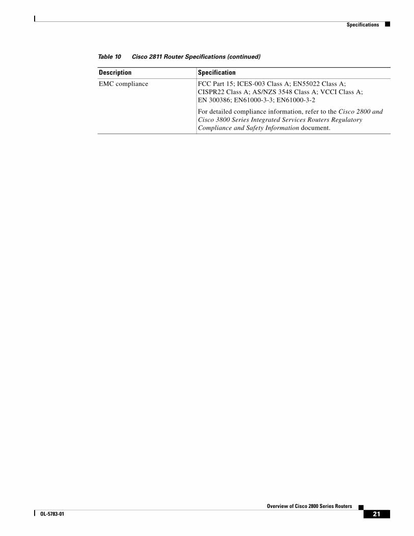
EMC compliance FCC Part 15; ICES-003 Class A; EN55022 Class A; CISPR22 Class A; AS/NZS 3548 Class A; VCCI Class A; EN 300386; EN61000-3-3; EN61000-3-2
For detailed compliance information, refer to the Cisco 2800 and Cisco 3800 Series Integrated Services Routers Regulatory Compliance and Safety Information document.
Table 10 Cisco 2811 Router Specifications (continued)
Description Specification
21Overview of Cisco 2800 Series Routers
OL-5783-01
Specifications
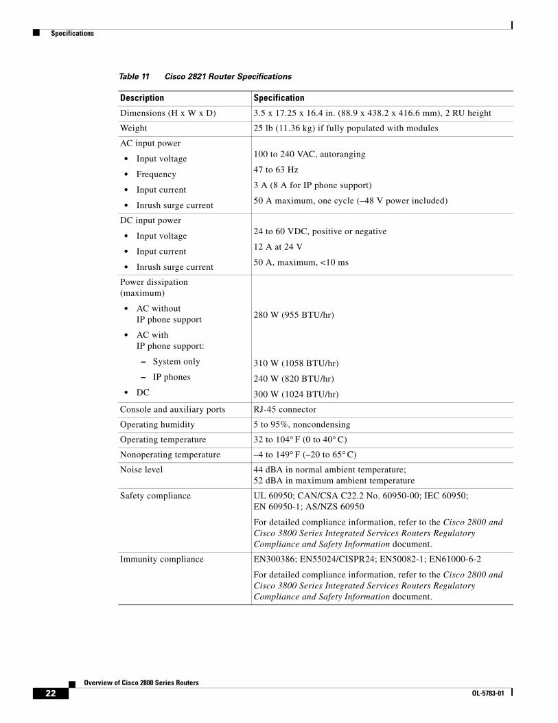
Table 11 Cisco 2821 Router Specifications
Description Specification
Dimensions (H x W x D) 3.5 x 17.25 x 16.4 in. (88.9 x 438.2 x 416.6 mm), 2 RU height
Weight 25 lb (11.36 kg) if fully populated with modules
AC input power
• Input voltage
• Frequency
• Input current
• Inrush surge current
100 to 240 VAC, autoranging
47 to 63 Hz
3 A (8 A for IP phone support)
50 A maximum, one cycle (–48 V power included)
DC input power
• Input voltage
• Input current
• Inrush surge current
24 to 60 VDC, positive or negative
12 A at 24 V
50 A, maximum, <10 ms
Power dissipation(maximum)
• AC withoutIP phone support
• AC withIP phone support:
– System only
– IP phones
• DC
280 W (955 BTU/hr)
310 W (1058 BTU/hr)
240 W (820 BTU/hr)
300 W (1024 BTU/hr)
Console and auxiliary ports RJ-45 connector
Operating humidity 5 to 95%, noncondensing
Operating temperature 32 to 104° F (0 to 40° C)
Nonoperating temperature –4 to 149° F (–20 to 65° C)
Noise level 44 dBA in normal ambient temperature; 52 dBA in maximum ambient temperature
Safety compliance UL 60950; CAN/CSA C22.2 No. 60950-00; IEC 60950; EN 60950-1; AS/NZS 60950
For detailed compliance information, refer to the Cisco 2800 and Cisco 3800 Series Integrated Services Routers Regulatory Compliance and Safety Information document.
Immunity compliance EN300386; EN55024/CISPR24; EN50082-1; EN61000-6-2
For detailed compliance information, refer to the Cisco 2800 and Cisco 3800 Series Integrated Services Routers Regulatory Compliance and Safety Information document.
22Overview of Cisco 2800 Series Routers
OL-5783-01

Specifications
EMC compliance FCC Part 15; ICES-003 Class A; EN55022 Class A; CISPR22 Class A; AS/NZS 3548 Class A; VCCI Class A; EN 300386; EN61000-3-3; EN61000-3-2
For detailed compliance information, refer to the Cisco 2800 and Cisco 3800 Series Integrated Services Routers Regulatory Compliance and Safety Information document.
Table 11 Cisco 2821 Router Specifications (continued)
Description Specification
23Overview of Cisco 2800 Series Routers
OL-5783-01
Specifications
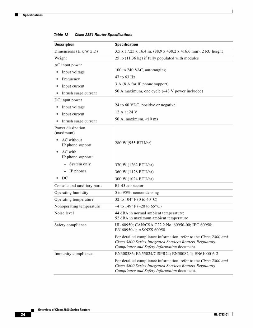
Table 12 Cisco 2851 Router Specifications
Description Specification
Dimensions (H x W x D) 3.5 x 17.25 x 16.4 in. (88.9 x 438.2 x 416.6 mm), 2 RU height
Weight 25 lb (11.36 kg) if fully populated with modules
AC input power
• Input voltage
• Frequency
• Input current
• Inrush surge current
100 to 240 VAC, autoranging
47 to 63 Hz
3 A (8 A for IP phone support)
50 A maximum, one cycle (–48 V power included)
DC input power
• Input voltage
• Input current
• Inrush surge current
24 to 60 VDC, positive or negative
12 A at 24 V
50 A, maximum, <10 ms
Power dissipation(maximum)
• AC withoutIP phone support
• AC withIP phone support:
– System only
– IP phones
• DC
280 W (955 BTU/hr)
370 W (1262 BTU/hr)
360 W (1128 BTU/hr)
300 W (1024 BTU/hr)
Console and auxiliary ports RJ-45 connector
Operating humidity 5 to 95%, noncondensing
Operating temperature 32 to 104° F (0 to 40° C)
Nonoperating temperature –4 to 149° F (–20 to 65° C)
Noise level 44 dBA in normal ambient temperature; 52 dBA in maximum ambient temperature
Safety compliance UL 60950; CAN/CSA C22.2 No. 60950-00; IEC 60950; EN 60950-1; AS/NZS 60950
For detailed compliance information, refer to the Cisco 2800 and Cisco 3800 Series Integrated Services Routers Regulatory Compliance and Safety Information document.
Immunity compliance EN300386; EN55024/CISPR24; EN50082-1; EN61000-6-2
For detailed compliance information, refer to the Cisco 2800 and Cisco 3800 Series Integrated Services Routers Regulatory Compliance and Safety Information document.
24Overview of Cisco 2800 Series Routers
OL-5783-01
Regulatory Compliance
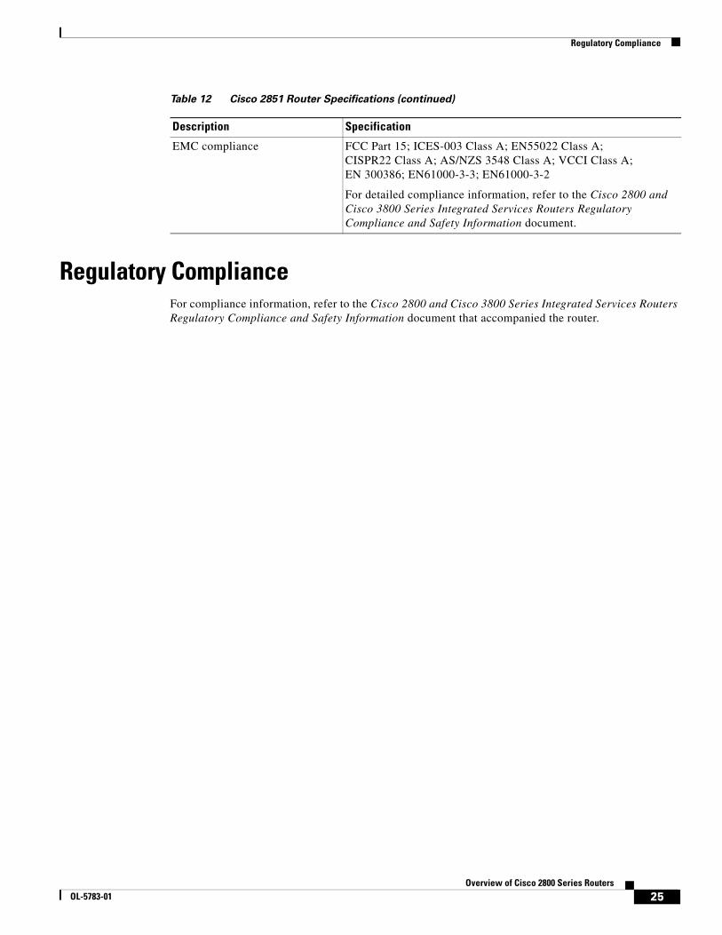
Regulatory ComplianceFor compliance information, refer to the Cisco 2800 and Cisco 3800 Series Integrated Services Routers Regulatory Compliance and Safety Information document that accompanied the router.
EMC compliance FCC Part 15; ICES-003 Class A; EN55022 Class A; CISPR22 Class A; AS/NZS 3548 Class A; VCCI Class A; EN 300386; EN61000-3-3; EN61000-3-2
For detailed compliance information, refer to the Cisco 2800 and Cisco 3800 Series Integrated Services Routers Regulatory Compliance and Safety Information document.
Table 12 Cisco 2851 Router Specifications (continued)
Description Specification
25Overview of Cisco 2800 Series Routers
OL-5783-01
Regulatory Compliance
Copyright © 2004 Cisco Systems, Inc. All rights reserved.
CCVP, the Cisco logo, and Welcome to the Human Network are trademarks of Cisco Systems, Inc.; Changing the Way We Work, Live, Play, and Learn isa service mark of Cisco Systems, Inc.; and Access Registrar, Aironet, Catalyst, CCDA, CCDP, CCIE, CCIP, CCNA, CCNP, CCSP, Cisco, the CiscoCertified Internetwork Expert logo, Cisco IOS, Cisco Press, Cisco Systems, Cisco Systems Capital, the Cisco Systems logo, Cisco Unity,Enterprise/Solver, EtherChannel, EtherFast, EtherSwitch, Fast Step, Follow Me Browsing, FormShare, GigaDrive, HomeLink, Internet Quotient, IOS,iPhone, IP/TV, iQ Expertise, the iQ logo, iQ Net Readiness Scorecard, iQuick Study, LightStream, Linksys, MeetingPlace, MGX, Networkers,Networking Academy, Network Registrar, PIX, ProConnect, ScriptShare, SMARTnet, StackWise, The Fastest Way to Increase Your Internet Quotient,and TransPath are registered trademarks of Cisco Systems, Inc. and/or its affiliates in the United States and certain other countries.
All other trademarks mentioned in this document or Website are the property of their respective owners. The use of the word partner does not imply apartnership relationship between Cisco and any other company. (0711R)
26Overview of Cisco 2800 Series Routers
OL-5783-01
![Cisco Small Form-Factor Pluggable (SFP) トラン …SFP トランシーバ モジュール[光ファイバ LC コネクタ] 1000BASE-T SFP トランシーバ モジュール [RJ-45](https://img.pdfslide.net/doc/110x75/5fa24c6121d8c8099547a531/cisco-small-form-factor-pluggable-isfpi-fff-sfp-fffff-ffffff.jpg)