Embed Size (px)
Citation preview
American Institute of Aeronautics and Astronautics
1
Overview of the NASA Environmentally Responsible Aviation Project’s Propulsion Technology Portfolio
Kenneth L Suder1 NASA Glenn Research Center, Cleveland, OH, 44135
The NASA Environmentally Responsible Aviation (ERA) Project is focused on developing and demonstrating integrated systems technologies to TRL 4-6 by 2020 that enable reduced fuel burn, emissions, and noise for futuristic air vehicles. The specific goals aim to simultaneously reduce fuel burn by 50%, reduce Landing and Take-off Nitrous Oxides emissions by 75% relative to the CAEP 6 guidelines, and reduce cumulative noise by 42 Decibels relative to the Stage 4 guidelines. These goals apply to the integrated vehicle and propulsion system and are based on a reference mission of 3000nm flight of a Boeing 777-200 with GE90 engines. This paper will focus primarily on the ERA propulsion technology portfolio, which consists of advanced combustion, propulsor, and core technologies to enable these integrated air vehicle systems goals. An overview of the ERA propulsion technologies will be described and the status and results to date will be presented.
Nomenclature ASCR Advanced Subsonic Combustor Rig BPR Bypass Ratio CAEP Committee on Aviation Environmental Protection CFD Computational Fluid Dynamics CMC Ceramic Matrix Composite CRESS Counter Rotating Externally Staged Swirler EBC Environmental Barrier Coating ERA Environmentally Responsible Aviation FPR Fan Pressure Ratio GE General Electric GRC Glenn Research Center GTF Geared TurboFan ICAO International Civil Aviation Organization LTO Landing and Take-Off NOx Nitrous Oxides OPR Overall Pressure Ratio OTR Over-The-Rotor P&W Pratt & Whitney RQL Rich Quench Lean
1 Aerospace Engineer, Aeronautics Office, 21000 Brookpark Road MS 5-10, AIAA Member.
https://ntrs.nasa.gov/search.jsp?R=20140012638 2020-01-04T18:47:43+00:00Z
American Institute of Aeronautics and Astronautics
2
SFC Specific Fuel Consumption SV Soft Vane TAPS Twin Annular Premixing Swirler TRL Technology Readiness Level UEET Ultra Efficient Engine Technology UHB Ultra High Bypass
I. Introduction The goal of the NASA Environmentally Responsible Aviation (ERA) project is to explore and document the feasibility, benefits, and technical risks of vehicle concepts and enabling technologies identified to have the potential to mitigate the impact of aviation on the environment. Through system-level analysis, promising vehicle and propulsion concepts and technologies will be down-selected based on their potential benefit towards simultaneously achieving fuel burn, noise and emissions metrics consistent with the NASA subsonic transport goals as shown in Table 1 below. ERA is focused on developing and demonstrating technologies to Technology Readiness Level (TRL) 4-6 by the 2020 time frame as defined by the goals defined in the column identified as N+ 2 goals of Table 1 (Ref. 1). These concepts and technologies will then be matured and their performance will be evaluated at the system and sub-system level in relevant environments and across the vehicle fleet (Ref 2). Among the concepts and technologies to be explored are the following: • Advanced aircraft system architectures that enable simultaneous achievement of noise, Landing Take Off
(LTO) NOx and fuel burn goals in the N+2 timeframe (see table below) • Drag reduction through laminar flow • Advanced composite structural concepts for weight reduction • Low NOx, fuel-flexible combustors • Integration of advanced UHB engines for noise reduction and fuel burn improvements
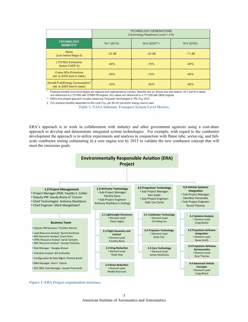
In Table 1, the Subsonic Transport System Level Metrics are shown, outlining the environmental fuel burn, noise and emissions reduction goals, the time frame for achieving them, and the baseline defined for comparing with new technologies. Though these goals are aggressive they are based on integrating advanced propulsion and airframe technologies and flying the vehicle through a reference mission and comparing to a 1998 baseline mission. To this end the ERA project is organized as shown in Figure 1 where the major subprojects consist of airframe technology, propulsion technology, and vehicle systems integration. It is evident to achieve the goals defined in the N+2 column of Table 1 significant advancements and technology developments are required. First, to achieve the 50% fuel burn reduction goal the following technologies are being developed and/or demonstrated: 1) drag reduction by extending the laminar flow regions on the aircraft surfaces using natural and hybrid laminar flow technologies. 2) weight reduction by developing and demonstrating advanced composite structures, and 3) reduction of engine specific fuel consumption by improving both propulsive and thermal efficiency of the gas turbine engines. Similarly, the noise goals are being addressed by the following technologies: 1) reduction of airframe noise by reducing the noise attributed to high lift systems and landing gear, 2) reduction of propulsion noise by addressing fan, core and jet noise, and 3) optimizing propulsion air frame integration to minimize the propulsion airframe aero acoustics. To reduce nitrous oxides emissions, ERA is developing advanced concepts to enable a low NOx fuel flexible combustor inclusive of lean direct injection concepts, advanced Ceramic Matrix Composite (CMC) liners with advanced environmental coatings, and combustion control strategies to enable stable lean burn combustion.
American Institute of Aeronautics and Astronautics 3
Table 1: NASA Subsonic Transport System Level Metrics.
ERA’s approach is to work in collaboration with industry and other government agencies using a cost-share approach to develop and demonstrate integrated system technologies. For example, with regard to the combustor development the approach is to utilize experiments and analysis in conjunction with flame tube, sector-rig, and full-scale combustor testing culminating in a core engine test by 2015 to validate the new combustor concept that will meet the emissions goals.
Figure 1: ERA Project organization structure.
TECHNOLOGYBENEFITS* N+1 (2015) N+2 (2020**) N+3 (2025)
Noise(cum below Stage 4) - 32 dB - 42 dB - 71 dB
LTO NOx Emissions(below CAEP 6) -60% -75% -80%
Cruise NOx Emissions(rel. to 2005 best in class) -55% -70% -80%
Aircraft Fuel/Energy Consumption‡
(rel. to 2005 best in class)-33% -50% -60%
‡ CO2 emission benefits dependent on life-cycle CO2e per MJ for fuel and/or energy source used
TECHNOLOGY GENERATIONS(Technology Readiness Level = 4-6)
* Projected benefits once technologies are matured and implemented by industry. Benefits vary by vehicle size and mission; N+1 and N+3 values are referenced to a 737-800 with CFM56-7B engines, N+2 values are referenced to a 777-200 with GE90 engines** ERA's time phased approach includes advancing "long-pole" technologies to TRL 6 by 2015
������������• ������������ ������� �������������
• ���������������������������������������• ����������������������������� ����• ��!��������������������� ����� �������• ����������������������������"����������
• �� ������"��������"�������#��
• � ������������������ ����� ���$��
• ����%"���&���'������"����������������
• �(������"���� ���� ��)�����
• ��*��(�����������"����+������ ����#�� �
�� ������������������������� �������������������
������������ �!������• ���,�������"���-.��!���$�� /����� ���• ������������������0��12 �������• ��� �3���������" ����������������4����• ��� �3�5�" ������������"������3�
"������#������$����!��• � �41��,�������"�����
��������6 ��• � �41��,����5�" �������
������������4����-���&�".�
%����������������$����!��• � �41��,�������"�����
7��� �����• � �41��,����5�" �������
�����*���8�����
&���'�$�����(�������)���!�����
• � �41��,�������"����9�� �����!�������0�
• � �41��,����5�" ���������������������
"���*�!$�+��!$��(����������• �5����������������#��+�"����
�
"�"�,��!$��-��������.�/�������
• �5��������������� ������� ����
�:/;�� "��#� "���
����������5������������
�
"�&�0�������.������• �5����������������� �7������ �
�
%�%�/������$����!��• �5��������������+�����9� ������
�
%�"�������������$����!��• �5��������������
�� ���! ����
%���/�����������$����!��• �5���������������� 1 �"�����
�
&�"���������������#����)���!�����
• �5�������������� ��6�� � ���
�&�%���������������#����
������������• �5��������������������������
�
&���(���������������• �5����������������� "�( �����
�
"�%�-�!���.������• �5��������������
�����7 �"��
&�&��. ���.�'�$�����/��������
• �5����������������� "�( �����
�
American Institute of Aeronautics and Astronautics
4
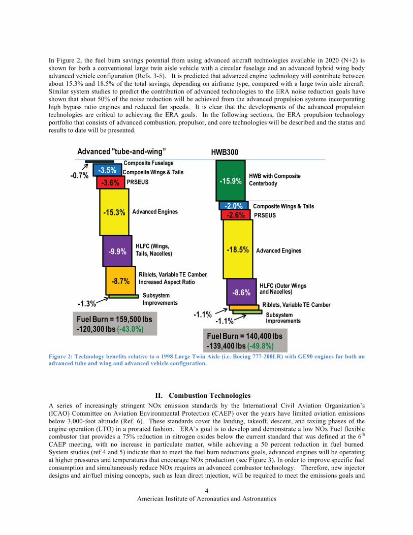
In Figure 2, the fuel burn savings potential from using advanced aircraft technologies available in 2020 (N+2) is shown for both a conventional large twin aisle vehicle with a circular fuselage and an advanced hybrid wing body advanced vehicle configuration (Refs. 3-5). It is predicted that advanced engine technology will contribute between about 15.3% and 18.5% of the total savings, depending on airframe type, compared with a large twin aisle aircraft. Similar system studies to predict the contribution of advanced technologies to the ERA noise reduction goals have shown that about 50% of the noise reduction will be achieved from the advanced propulsion systems incorporating high bypass ratio engines and reduced fan speeds. It is clear that the developments of the advanced propulsion technologies are critical to achieving the ERA goals. In the following sections, the ERA propulsion technology portfolio that consists of advanced combustion, propulsor, and core technologies will be described and the status and results to date will be presented.
Figure 2: Technology benefits relative to a 1998 Large Twin Aisle (i.e. Boeing 777-200LR) with GE90 engines for both an advanced tube and wing and advanced vehicle configuration.
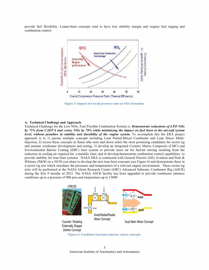
II. Combustion Technologies A series of increasingly stringent NOx emission standards by the International Civil Aviation Organization’s (ICAO) Committee on Aviation Environmental Protection (CAEP) over the years have limited aviation emissions below 3,000-foot altitude (Ref. 6). These standards cover the landing, takeoff, descent, and taxiing phases of the engine operation (LTO) in a prorated fashion. ERA’s goal is to develop and demonstrate a low NOx Fuel flexible combustor that provides a 75% reduction in nitrogen oxides below the current standard that was defined at the 6th CAEP meeting, with no increase in particulate matter, while achieving a 50 percent reduction in fuel burned. System studies (ref 4 and 5) indicate that to meet the fuel burn reductions goals, advanced engines will be operating at higher pressures and temperatures that encourage NOx production (see Figure 3). In order to improve specific fuel consumption and simultaneously reduce NOx requires an advanced combustor technology. Therefore, new injector designs and air/fuel mixing concepts, such as lean direct injection, will be required to meet the emissions goals and
-15.9%HWB with CompositeCenterbody
-8.7%
-3.5%
-3.6%
-15.3%
-9.9%
Composite Fuselage
Composite Wings & Tails
PRSEUS
Advanced Engines
HLFC (Wings, Tails, Nacelles)
Riblets, Variable TE Camber, Increased Aspect Ratio
Subsystem Improvements
-2.0% Composite Wings & Tails
-2.6% PRSEUS
-18.5% Advanced Engines
-8.6%HLFC (Outer Wings and Nacelles)
Riblets, Variable TE Camber
Subsystem Improvements
Advanced "tube-and-wing” HWB300
Fuel Burn = 159,500 lbs-120,300 lbs (-43.0%)
Fuel Burn = 140,400 lbs-139,400 lbs (-49.8%)
-0.7%
-1.3%-1.1%
-1.1%
American Institute of Aeronautics and Astronautics
5
provide fuel flexibility. Leaner-burn concepts tend to have less stability margin and require fuel staging and combustion control.
Figure 3: Impact of overall pressure ratio on NOx formation.
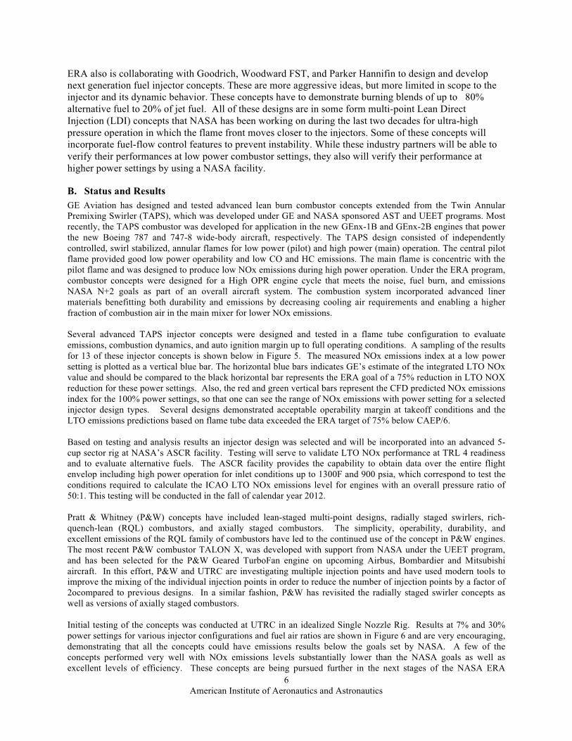
A. Technical Challenge and Approach Technical Challenge for the Low NOx, Fuel Flexible Combustion System is: Demonstrate reductions of LTO NOx by 75% from CAEP 6 and cruise NOx by 70% while minimizing the impact on fuel burn at the aircraft system level, without penalties in stability and durability of the engine system. To accomplish this the ERA project approach is to 1) pursue multiple concepts including Lean Partial-Mixed Combustor and Lean Direct Multi-Injection, 2) screen these concepts in flame tube tests and down select the most promising candidates for sector rig and annular combustor development and testing, 3) develop an integrated Ceramic Matrix Composite (CMC) and Environmental Barrier Coating (EBC) liner system to provide more air for fuel/air mixing resulting from the reduction in cooling air required for a metallic liner, and 4) develop/demonstrate combustion control capabilities to provide stability for lean burn systems. NASA ERA is contracted with General Electric (GE) Aviation and Pratt & Whitney (P&W) in a 50/50 cost share to develop the new lean burn concepts (see Figure 4) and demonstrate these in a sector rig test which simulates the pressures and temperatures of a relevant engine environment. These sector rig tests will be performed at the NASA Glenn Research Center (GRC) Advanced Subsonic Combustor Rig (ASCR) during the first 9 months of 2012. The NASA ASCR facility has been upgraded to provide combustor entrance conditions up to a pressure of 900 psia and temperature up to 1300F.
Figure 4: Candidate lean burn injector /mixer concepts.
Radial 1
Radial 2
Axial
Axial/Radial/Radial Mixer Concept
Axial
Axial
Dual Main Mixer Concept
CRESS
Counter- Rotating Externally Staged Swirler Concept
American Institute of Aeronautics and Astronautics
6
ERA also is collaborating with Goodrich, Woodward FST, and Parker Hannifin to design and develop next generation fuel injector concepts. These are more aggressive ideas, but more limited in scope to the injector and its dynamic behavior. These concepts have to demonstrate burning blends of up to 80% alternative fuel to 20% of jet fuel. All of these designs are in some form multi-point Lean Direct Injection (LDI) concepts that NASA has been working on during the last two decades for ultra-high pressure operation in which the flame front moves closer to the injectors. Some of these concepts will incorporate fuel-flow control features to prevent instability. While these industry partners will be able to verify their performances at low power combustor settings, they also will verify their performance at higher power settings by using a NASA facility.
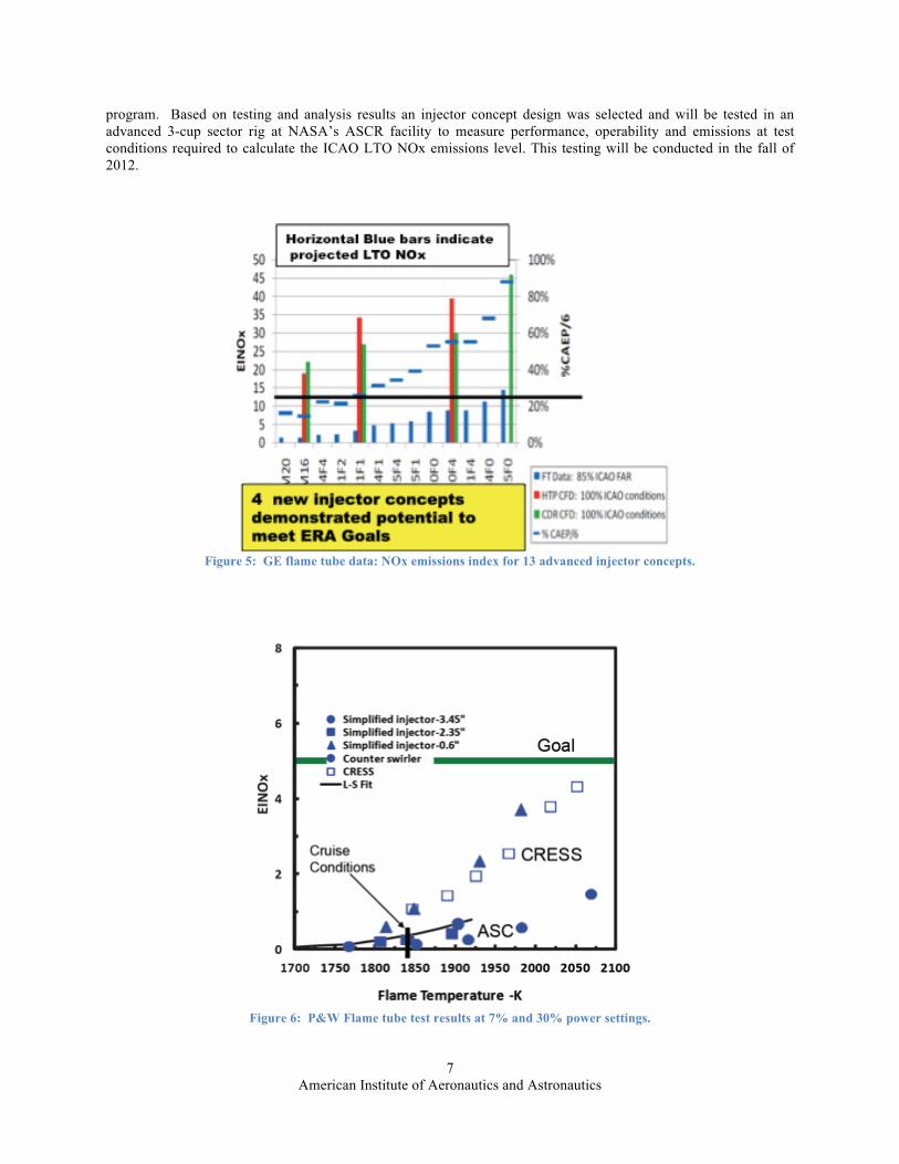
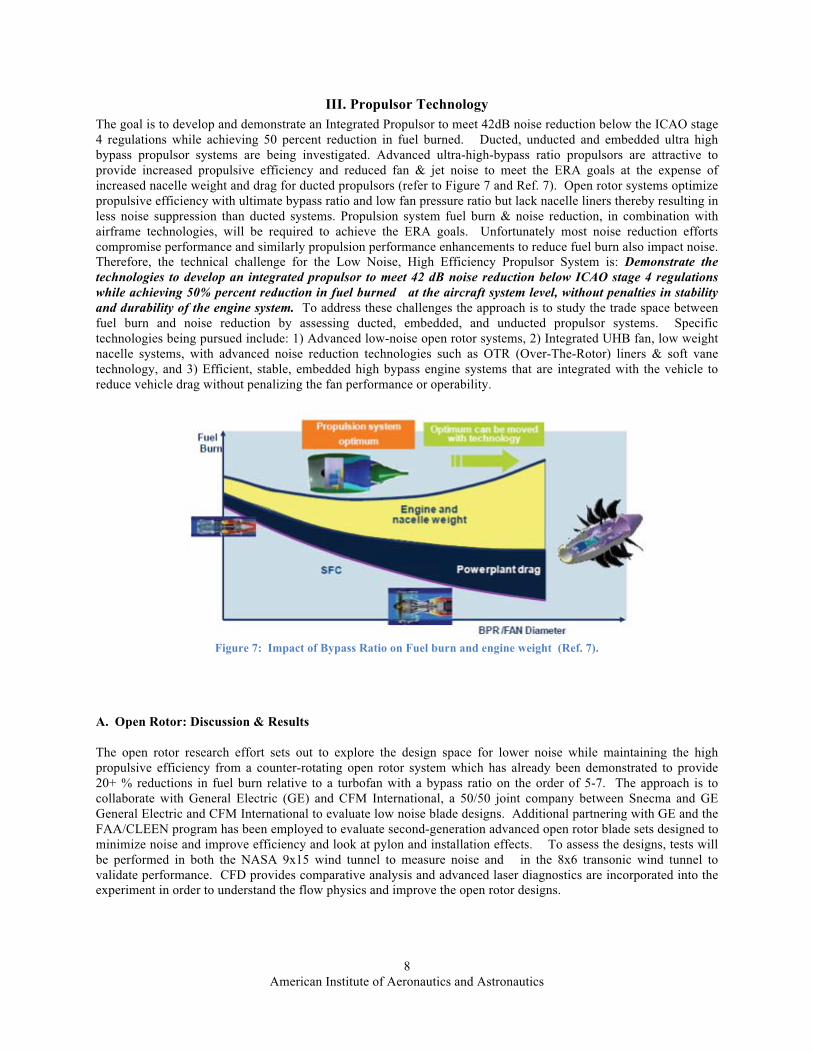
B. Status and Results GE Aviation has designed and tested advanced lean burn combustor concepts extended from the Twin Annular Premixing Swirler (TAPS), which was developed under GE and NASA sponsored AST and UEET programs. Most recently, the TAPS combustor was developed for application in the new GEnx-1B and GEnx-2B engines that power the new Boeing 787 and 747-8 wide-body aircraft, respectively. The TAPS design consisted of independently controlled, swirl stabilized, annular flames for low power (pilot) and high power (main) operation. The central pilot flame provided good low power operability and low CO and HC emissions. The main flame is concentric with the pilot flame and was designed to produce low NOx emissions during high power operation. Under the ERA program, combustor concepts were designed for a High OPR engine cycle that meets the noise, fuel burn, and emissions NASA N+2 goals as part of an overall aircraft system. The combustion system incorporated advanced liner materials benefitting both durability and emissions by decreasing cooling air requirements and enabling a higher fraction of combustion air in the main mixer for lower NOx emissions. Several advanced TAPS injector concepts were designed and tested in a flame tube configuration to evaluate emissions, combustion dynamics, and auto ignition margin up to full operating conditions. A sampling of the results for 13 of these injector concepts is shown below in Figure 5. The measured NOx emissions index at a low power setting is plotted as a vertical blue bar. The horizontal blue bars indicates GE’s estimate of the integrated LTO NOx value and should be compared to the black horizontal bar represents the ERA goal of a 75% reduction in LTO NOX reduction for these power settings. Also, the red and green vertical bars represent the CFD predicted NOx emissions index for the 100% power settings, so that one can see the range of NOx emissions with power setting for a selected injector design types. Several designs demonstrated acceptable operability margin at takeoff conditions and the LTO emissions predictions based on flame tube data exceeded the ERA target of 75% below CAEP/6. Based on testing and analysis results an injector design was selected and will be incorporated into an advanced 5-cup sector rig at NASA’s ASCR facility. Testing will serve to validate LTO NOx performance at TRL 4 readiness and to evaluate alternative fuels. The ASCR facility provides the capability to obtain data over the entire flight envelop including high power operation for inlet conditions up to 1300F and 900 psia, which correspond to test the conditions required to calculate the ICAO LTO NOx emissions level for engines with an overall pressure ratio of 50:1. This testing will be conducted in the fall of calendar year 2012. Pratt & Whitney (P&W) concepts have included lean-staged multi-point designs, radially staged swirlers, rich-quench-lean (RQL) combustors, and axially staged combustors. The simplicity, operability, durability, and excellent emissions of the RQL family of combustors have led to the continued use of the concept in P&W engines. The most recent P&W combustor TALON X, was developed with support from NASA under the UEET program, and has been selected for the P&W Geared TurboFan engine on upcoming Airbus, Bombardier and Mitsubishi aircraft. In this effort, P&W and UTRC are investigating multiple injection points and have used modern tools to improve the mixing of the individual injection points in order to reduce the number of injection points by a factor of 2ocompared to previous designs. In a similar fashion, P&W has revisited the radially staged swirler concepts as well as versions of axially staged combustors. Initial testing of the concepts was conducted at UTRC in an idealized Single Nozzle Rig. Results at 7% and 30% power settings for various injector configurations and fuel air ratios are shown in Figure 6 and are very encouraging, demonstrating that all the concepts could have emissions results below the goals set by NASA. A few of the concepts performed very well with NOx emissions levels substantially lower than the NASA goals as well as excellent levels of efficiency. These concepts are being pursued further in the next stages of the NASA ERA
American Institute of Aeronautics and Astronautics 7
program. Based on testing and analysis results an injector concept design was selected and will be tested in an advanced 3-cup sector rig at NASA’s ASCR facility to measure performance, operability and emissions at test conditions required to calculate the ICAO LTO NOx emissions level. This testing will be conducted in the fall of 2012.
Figure 5: GE flame tube data: NOx emissions index for 13 advanced injector concepts.
Figure 6: P&W Flame tube test results at 7% and 30% power settings.
American Institute of Aeronautics and Astronautics 8
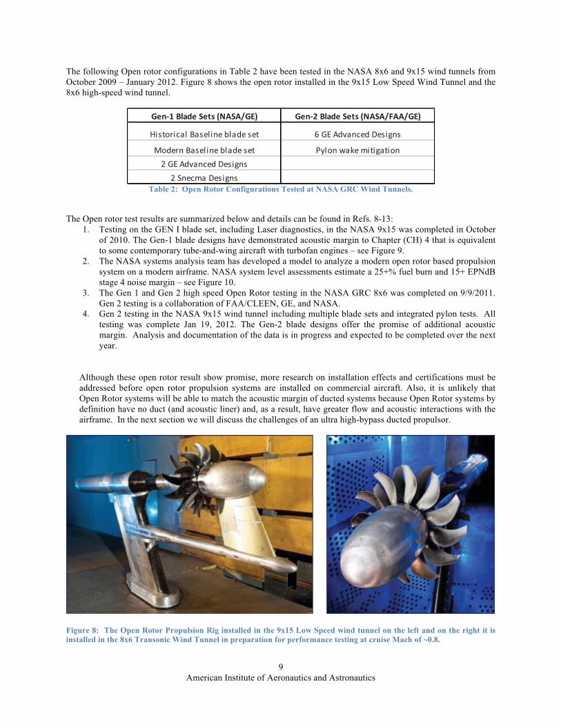
III. Propulsor Technology The goal is to develop and demonstrate an Integrated Propulsor to meet 42dB noise reduction below the ICAO stage 4 regulations while achieving 50 percent reduction in fuel burned. Ducted, unducted and embedded ultra high bypass propulsor systems are being investigated. Advanced ultra-high-bypass ratio propulsors are attractive to provide increased propulsive efficiency and reduced fan & jet noise to meet the ERA goals at the expense of increased nacelle weight and drag for ducted propulsors (refer to Figure 7 and Ref. 7). Open rotor systems optimize propulsive efficiency with ultimate bypass ratio and low fan pressure ratio but lack nacelle liners thereby resulting in less noise suppression than ducted systems. Propulsion system fuel burn & noise reduction, in combination with airframe technologies, will be required to achieve the ERA goals. Unfortunately most noise reduction efforts compromise performance and similarly propulsion performance enhancements to reduce fuel burn also impact noise. Therefore, the technical challenge for the Low Noise, High Efficiency Propulsor System is: Demonstrate the technologies to develop an integrated propulsor to meet 42 dB noise reduction below ICAO stage 4 regulations while achieving 50% percent reduction in fuel burned at the aircraft system level, without penalties in stability and durability of the engine system. To address these challenges the approach is to study the trade space between fuel burn and noise reduction by assessing ducted, embedded, and unducted propulsor systems. Specific technologies being pursued include: 1) Advanced low-noise open rotor systems, 2) Integrated UHB fan, low weight nacelle systems, with advanced noise reduction technologies such as OTR (Over-The-Rotor) liners & soft vanetechnology, and 3) Efficient, stable, embedded high bypass engine systems that are integrated with the vehicle to reduce vehicle drag without penalizing the fan performance or operability.
Figure 7: Impact of Bypass Ratio on Fuel burn and engine weight (Ref. 7).
A. Open Rotor: Discussion & Results
The open rotor research effort sets out to explore the design space for lower noise while maintaining the high propulsive efficiency from a counter-rotating open rotor system which has already been demonstrated to provide20+ % reductions in fuel burn relative to a turbofan with a bypass ratio on the order of 5-7. The approach is to collaborate with General Electric (GE) and CFM International, a 50/50 joint company between Snecma and GEGeneral Electric and CFM International to evaluate low noise blade designs. Additional partnering with GE and theFAA/CLEEN program has been employed to evaluate second-generation advanced open rotor blade sets designed to minimize noise and improve efficiency and look at pylon and installation effects. To assess the designs, tests will be performed in both the NASA 9x15 wind tunnel to measure noise and in the 8x6 transonic wind tunnel tovalidate performance. CFD provides comparative analysis and advanced laser diagnostics are incorporated into the experiment in order to understand the flow physics and improve the open rotor designs.
American Institute of Aeronautics and Astronautics
9
The following Open rotor configurations in Table 2 have been tested in the NASA 8x6 and 9x15 wind tunnels from October 2009 – January 2012. Figure 8 shows the open rotor installed in the 9x15 Low Speed Wind Tunnel and the 8x6 high-speed wind tunnel.
��������������� ������� ��������������� �����������
�������� �������� ������ ��������������������
�������������� ������ ��������������������������������������
��������������� Table 2: Open Rotor Configurations Tested at NASA GRC Wind Tunnels.
The Open rotor test results are summarized below and details can be found in Refs. 8-13:
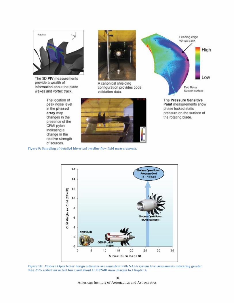
1. Testing on the GEN I blade set, including Laser diagnostics, in the NASA 9x15 was completed in October of 2010. The Gen-1 blade designs have demonstrated acoustic margin to Chapter (CH) 4 that is equivalent to some contemporary tube-and-wing aircraft with turbofan engines – see Figure 9.
2. The NASA systems analysis team has developed a model to analyze a modern open rotor based propulsion system on a modern airframe. NASA system level assessments estimate a 25+% fuel burn and 15+ EPNdB stage 4 noise margin – see Figure 10.
3. The Gen 1 and Gen 2 high speed Open Rotor testing in the NASA GRC 8x6 was completed on 9/9/2011. Gen 2 testing is a collaboration of FAA/CLEEN, GE, and NASA.
4. Gen 2 testing in the NASA 9x15 wind tunnel including multiple blade sets and integrated pylon tests. All testing was complete Jan 19, 2012. The Gen-2 blade designs offer the promise of additional acoustic margin. Analysis and documentation of the data is in progress and expected to be completed over the next year.
Although these open rotor result show promise, more research on installation effects and certifications must be addressed before open rotor propulsion systems are installed on commercial aircraft. Also, it is unlikely that Open Rotor systems will be able to match the acoustic margin of ducted systems because Open Rotor systems by definition have no duct (and acoustic liner) and, as a result, have greater flow and acoustic interactions with the airframe. In the next section we will discuss the challenges of an ultra high-bypass ducted propulsor.
Figure 8: The Open Rotor Propulsion Rig installed in the 9x15 Low Speed wind tunnel on the left and on the right it is installed in the 8x6 Transonic Wind Tunnel in preparation for performance testing at cruise Mach of ~0.8.
American Institute of Aeronautics and Astronautics 10
Figure 9: Sampling of detailed historical baseline flow field measurements.
Figure 10: Modern Open Rotor design estimates are consistent with NASA system level assessments indicating greater than 25% reduction in fuel burn and about 15 EPNdB noise margin to Chapter 4.
American Institute of Aeronautics and Astronautics 11
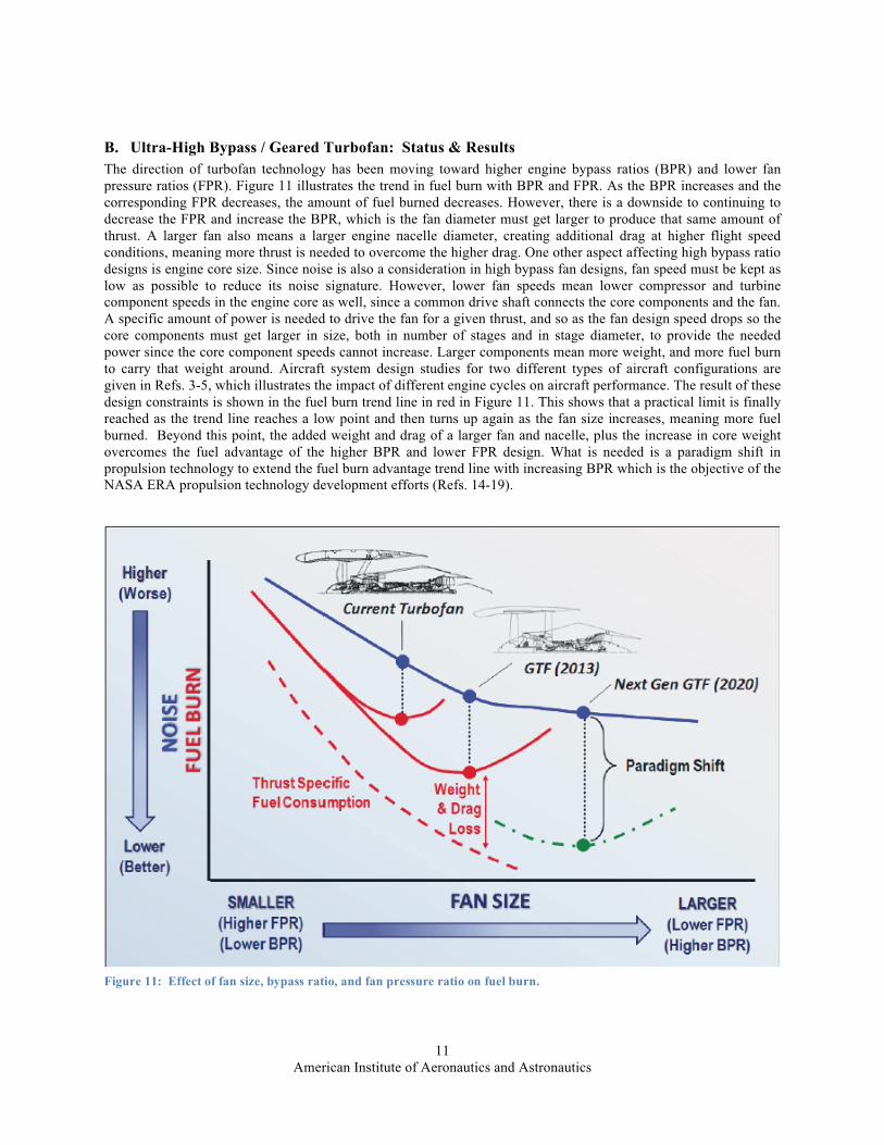
B. Ultra-High Bypass / Geared Turbofan: Status & Results The direction of turbofan technology has been moving toward higher engine bypass ratios (BPR) and lower fanpressure ratios (FPR). Figure 11 illustrates the trend in fuel burn with BPR and FPR. As the BPR increases and the corresponding FPR decreases, the amount of fuel burned decreases. However, there is a downside to continuing to decrease the FPR and increase the BPR, which is the fan diameter must get larger to produce that same amount of thrust. A larger fan also means a larger engine nacelle diameter, creating additional drag at higher flight speed conditions, meaning more thrust is needed to overcome the higher drag. One other aspect affecting high bypass ratio designs is engine core size. Since noise is also a consideration in high bypass fan designs, fan speed must be kept as low as possible to reduce its noise signature. However, lower fan speeds mean lower compressor and turbine component speeds in the engine core as well, since a common drive shaft connects the core components and the fan. A specific amount of power is needed to drive the fan for a given thrust, and so as the fan design speed drops so the core components must get larger in size, both in number of stages and in stage diameter, to provide the needed power since the core component speeds cannot increase. Larger components mean more weight, and more fuel burn to carry that weight around. Aircraft system design studies for two different types of aircraft configurations are given in Refs. 3-5, which illustrates the impact of different engine cycles on aircraft performance. The result of these design constraints is shown in the fuel burn trend line in red in Figure 11. This shows that a practical limit is finally reached as the trend line reaches a low point and then turns up again as the fan size increases, meaning more fuel burned. Beyond this point, the added weight and drag of a larger fan and nacelle, plus the increase in core weight overcomes the fuel advantage of the higher BPR and lower FPR design. What is needed is a paradigm shift in propulsion technology to extend the fuel burn advantage trend line with increasing BPR which is the objective of the NASA ERA propulsion technology development efforts (Refs. 14-19).
Figure 11: Effect of fan size, bypass ratio, and fan pressure ratio on fuel burn.
American Institute of Aeronautics and Astronautics
12
The objectives are to investigate aerodynamic performance, operability, and noise characteristics of 2nd Gen Pratt & Whitney (P&W) Geared TurboFan technology for both conventional and advanced nacelles with lower weight and drag, and to develop and demonstrate advanced noise reduction technologies for Ultra High Bypass engine cycles.
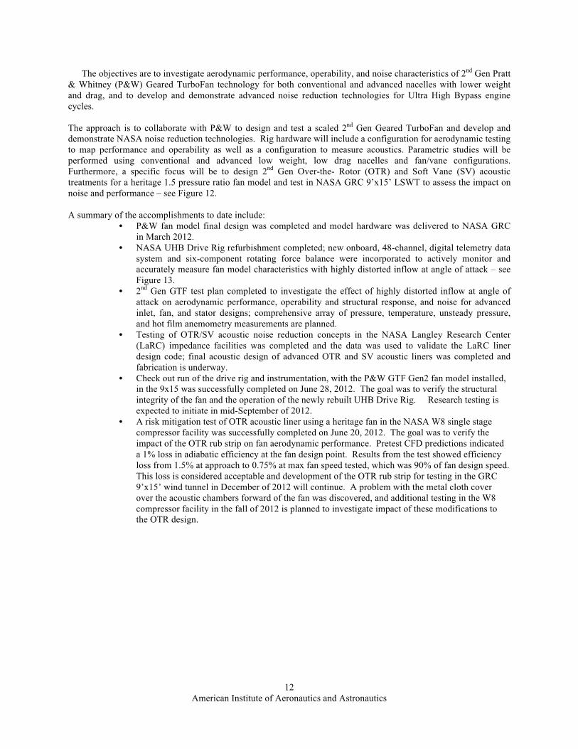
The approach is to collaborate with P&W to design and test a scaled 2nd Gen Geared TurboFan and develop and demonstrate NASA noise reduction technologies. Rig hardware will include a configuration for aerodynamic testing to map performance and operability as well as a configuration to measure acoustics. Parametric studies will be performed using conventional and advanced low weight, low drag nacelles and fan/vane configurations. Furthermore, a specific focus will be to design 2nd Gen Over-the- Rotor (OTR) and Soft Vane (SV) acoustic treatments for a heritage 1.5 pressure ratio fan model and test in NASA GRC 9’x15’ LSWT to assess the impact on noise and performance – see Figure 12.
A summary of the accomplishments to date include:
• P&W fan model final design was completed and model hardware was delivered to NASA GRC in March 2012.
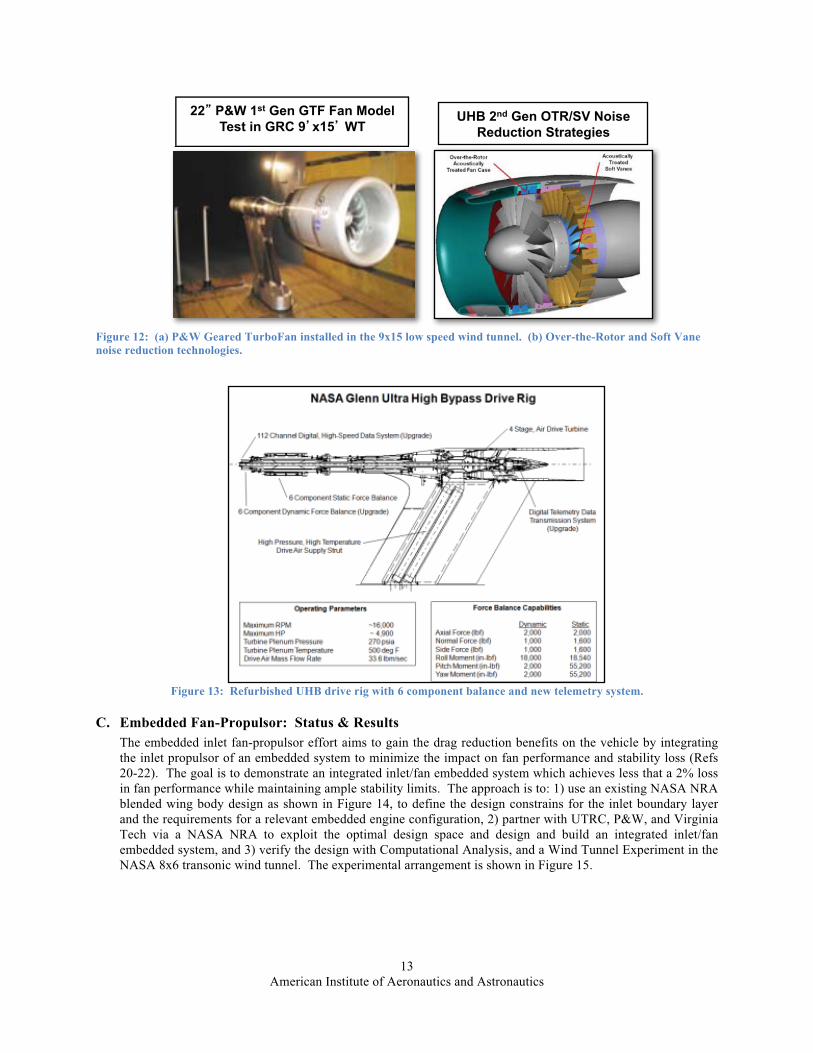
• NASA UHB Drive Rig refurbishment completed; new onboard, 48-channel, digital telemetry data system and six-component rotating force balance were incorporated to actively monitor and accurately measure fan model characteristics with highly distorted inflow at angle of attack – see Figure 13.
• 2nd Gen GTF test plan completed to investigate the effect of highly distorted inflow at angle of attack on aerodynamic performance, operability and structural response, and noise for advanced inlet, fan, and stator designs; comprehensive array of pressure, temperature, unsteady pressure, and hot film anemometry measurements are planned.
• Testing of OTR/SV acoustic noise reduction concepts in the NASA Langley Research Center (LaRC) impedance facilities was completed and the data was used to validate the LaRC liner design code; final acoustic design of advanced OTR and SV acoustic liners was completed and fabrication is underway.
• Check out run of the drive rig and instrumentation, with the P&W GTF Gen2 fan model installed, in the 9x15 was successfully completed on June 28, 2012. The goal was to verify the structural integrity of the fan and the operation of the newly rebuilt UHB Drive Rig. Research testing is expected to initiate in mid-September of 2012.
• A risk mitigation test of OTR acoustic liner using a heritage fan in the NASA W8 single stage compressor facility was successfully completed on June 20, 2012. The goal was to verify the impact of the OTR rub strip on fan aerodynamic performance. Pretest CFD predictions indicated a 1% loss in adiabatic efficiency at the fan design point. Results from the test showed efficiency loss from 1.5% at approach to 0.75% at max fan speed tested, which was 90% of fan design speed. This loss is considered acceptable and development of the OTR rub strip for testing in the GRC 9’x15’ wind tunnel in December of 2012 will continue. A problem with the metal cloth cover over the acoustic chambers forward of the fan was discovered, and additional testing in the W8 compressor facility in the fall of 2012 is planned to investigate impact of these modifications to the OTR design.
American Institute of Aeronautics and Astronautics 13
Figure 12: (a) P&W Geared TurboFan installed in the 9x15 low speed wind tunnel. (b) Over-the-Rotor and Soft Vane noise reduction technologies.
Figure 13: Refurbished UHB drive rig with 6 component balance and new telemetry system.
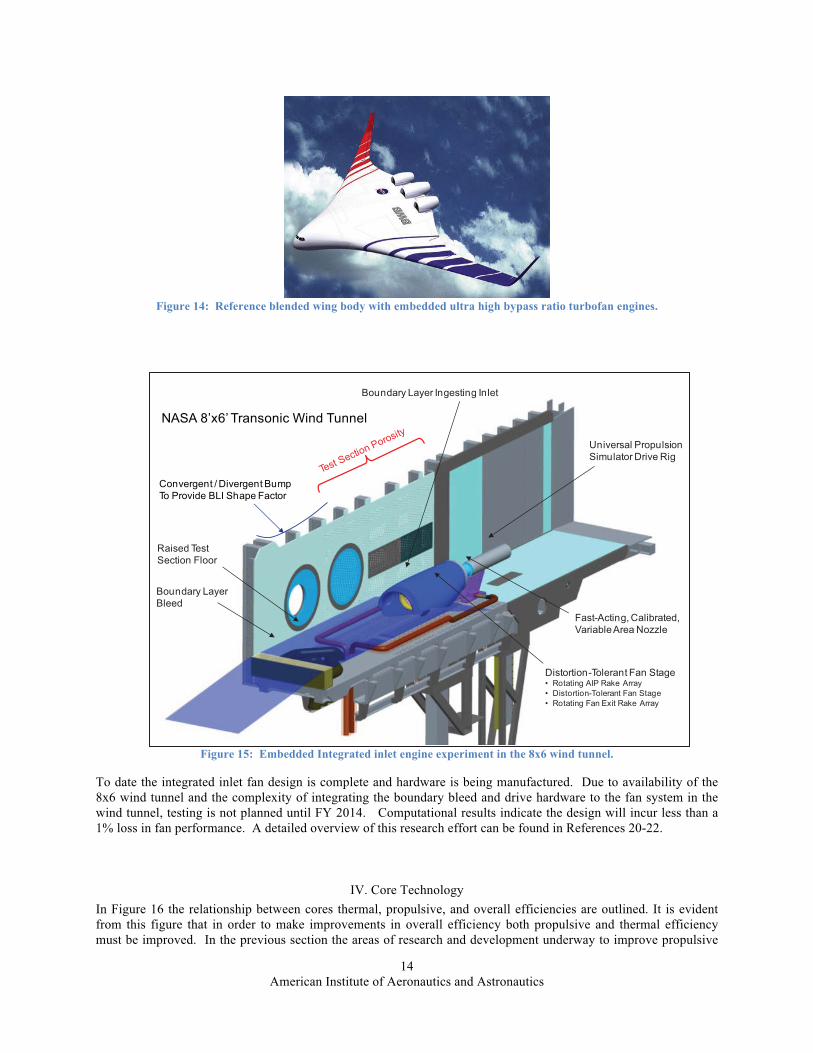
C. Embedded Fan-Propulsor: Status & Results The embedded inlet fan-propulsor effort aims to gain the drag reduction benefits on the vehicle by integrating the inlet propulsor of an embedded system to minimize the impact on fan performance and stability loss (Refs 20-22). The goal is to demonstrate an integrated inlet/fan embedded system which achieves less that a 2% loss in fan performance while maintaining ample stability limits. The approach is to: 1) use an existing NASA NRA blended wing body design as shown in Figure 14, to define the design constrains for the inlet boundary layer and the requirements for a relevant embedded engine configuration, 2) partner with UTRC, P&W, and Virginia Tech via a NASA NRA to exploit the optimal design space and design and build an integrated inlet/fanembedded system, and 3) verify the design with Computational Analysis, and a Wind Tunnel Experiment in the NASA 8x6 transonic wind tunnel. The experimental arrangement is shown in Figure 15.
UHB 2nd Gen OTR/SV Noise Reduction Strategies
22 P&W 1st Gen GTF Fan Model Test in GRC 9 x15 WT
American Institute of Aeronautics and Astronautics
14
Figure 14: Reference blended wing body with embedded ultra high bypass ratio turbofan engines.
Figure 15: Embedded Integrated inlet engine experiment in the 8x6 wind tunnel.
To date the integrated inlet fan design is complete and hardware is being manufactured. Due to availability of the 8x6 wind tunnel and the complexity of integrating the boundary bleed and drive hardware to the fan system in the wind tunnel, testing is not planned until FY 2014. Computational results indicate the design will incur less than a 1% loss in fan performance. A detailed overview of this research effort can be found in References 20-22.
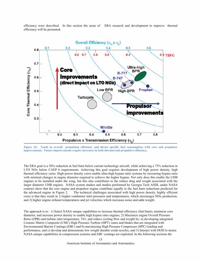
IV. Core Technology In Figure 16 the relationship between cores thermal, propulsive, and overall efficiencies are outlined. It is evident from this figure that in order to make improvements in overall efficiency both propulsive and thermal efficiency must be improved. In the previous section the areas of research and development underway to improve propulsive
Boundary LayerBleed
Raised TestSection Floor
Boundary Layer Ingesting Inlet
Universal PropulsionSimulator Drive Rig
Fast-Acting, Calibrated,Variable Area Nozzle
Distortion-Tolerant Fan Stage• Rotating AIP Rake Array• Distortion-Tolerant Fan Stage• Rotating Fan Exit Rake Array
Convergent / Divergent BumpTo Provide BLI Shape Factor
NASA 8’x6’ Transonic Wind Tunnel
American Institute of Aeronautics and Astronautics 15
efficiency were described. In this section the areas of ERA research and development to improve thermal efficiency will be presented.
The ERA goal is a 50% reduction in fuel burn below current technology aircraft, while achieving a 75% reduction in LTO NOx below CAEP 6 requirements. Achieving this goal requires development of high power density, high thermal efficiency cores. High power density cores enable ultra-high bypass ratio systems by increasing bypass ratio with minimal changes in engine diameter required to achieve the higher bypass. Not only does this enable the UHB engines to be installed under the wing, but this also contributes to the reduce drag and weight associated with the larger diameter UHB engines. NASA system studies and studies performed by Georgia Tech ASDL under NASA contract show that the core engine and propulsor engine contribute equally to the fuel burn reductions predicted forthe advanced engine in Figure 2. The technical challenges associated with high power density, highly efficient cores is that they result in 1) higher combustor inlet pressures and temperatures, which encourages NOx production, and 2) higher engine exhaust temperatures and jet velocities which increases noise and adds weight.
The approach is to: 1) Select NASA unique capabilities to increase thermal efficiency (fuel burn), minimize core diameter, and increase power density to enable high bypass ratio engines, 2) Maximize engine Overall Pressure Ratio (OPR) and turbine inlet temperature, T41, and reduce cooling flow and weight by: a) developing integrated Ceramic Matrix Composite (CMC) High Pressure Turbine (HPT) vanes and blades that are integrated with Environmental Barrier Coatings (EBC) and b) maximizing High Pressure Compressor (HPC) loading and performance, and c) develop and demonstrate low weight durable oxide nozzles, and 3) Interact with DOD to insure NASA unique capabilities in compression systems and EBC coatings are exploited. In the following sections the
Figure 16: Tends in overall propulsion efficiency and thrust specific fuel consumption with core and propulsorimprovements. Future improvements require increases in both thermal and propulsive efficiency.
American Institute of Aeronautics and Astronautics 16
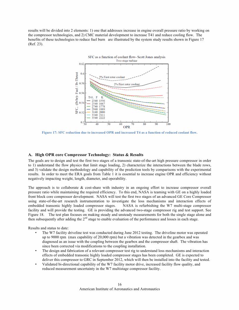
results will be divided into 2 elements: 1) one that addresses increase in engine overall pressure ratio by working on the compressor technologies, and 2) CMC material development to increase T41 and reduce cooling flow. The benefits of these technologies to reduce fuel burn are illustrated by the system study results shown in Figure 17 (Ref. 23).
Figure 17: SFC reduction due to increased OPR and increased T4 as a function of reduced coolant flow.
A. High OPR core Compressor Technology: Status & Results The goals are to design and test the first two stages of a transonic state-of-the-art high pressure compressor in order to 1) understand the flow physics that limit stage loading, 2) characterize the interactions between the blade rows, and 3) validate the design methodology and capability of the prediction tools by comparisons with the experimental results. In order to meet the ERA goals from Table 1 it is essential to increase engine OPR and efficiency without negatively impacting weight, length, diameter, and operability.
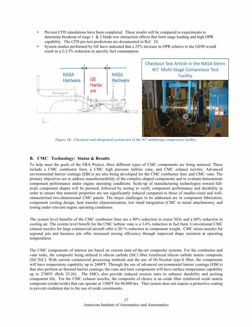
The approach is to collaborate & cost-share with industry in an ongoing effort to increase compressor overall pressure ratio while maintaining the required efficiency. To this end, NASA is teaming with GE on a highly loadedfront block core compressor development. NASA will test the first two stages of an advanced GE Core Compressor using state-of-the-art research instrumentation to investigate the loss mechanisms and interaction effects of embedded transonic highly loaded compressor stages. NASA is refurbishing the W7 multi-stage compressor facility and will provide the testing. GE is providing the advanced two-stage compressor rig and test support. See Figure 18. The test plan focuses on making steady and unsteady measurements for both the single stage alone and then subsequently after adding the 2nd stage to enable evaluation of the performance and losses in each stage.
Results and status to date: • The W7 facility driveline test was conducted during June 2012 testing. The driveline motor was operated
up to 9000 rpm (max capability of 20,000 rpm) but a vibration was detected in the gearbox and was diagnosed as an issue with the coupling between the gearbox and the compressor shaft. The vibration has since been corrected via modifications to the coupling installation.
• The design and fabrication of a relevant compressor test rig to understand loss mechanisms and interaction effects of embedded transonic highly loaded compressor stages has been completed. GE is expected to deliver this compressor to GRC in September 2012, which will then be installed into the facility and tested.
• Validated bi-directional capability of the W7 facility motor drive, increased facility flow quality, and reduced measurement uncertainty in the W7 multistage compressor facility.
American Institute of Aeronautics and Astronautics 17
• Pre-test CFD simulations have been completed. These results will be compared to experiments to determine breakout of stage 1 & 2 blade row interaction effects that limit stage loading and high OPR capability. The CFD pre-test predictions are documented in Ref. 24.
• System studies performed by GE have indicated that a 25% increase in OPR relative to the GE90 would result in a 2-2.5% reduction in specific fuel consumption.
Figure 18: Checkout and integrated system test of the W7 multistage compressor facility.
B. CMC Technology: Status & Results To help meet the goals of the ERA Project, three different types of CMC components are being matured. These include a CMC combustor liner, a CMC high pressure turbine vane, and CMC exhaust nozzles. Advanced environmental barrier coatings (EBCs) are also being developed for the CMC combustor liner and CMC vane. The primary objectives are to address manufacturability of the complex-shaped components and to evaluate/demonstrate component performance under engine operating conditions. Scale-up of manufacturing technologies toward full-scale component shapes will be pursued; followed by testing to verify component performance and durability in order to ensure that material properties are not significantly reduced compared to those of smaller-sized and well-characterized two-dimensional CMC panels. The major challenges to be addressed are in component fabrication, component cooling design, heat transfer characterization, test stand integration (CMC to metal attachments), and testing under relevant engine operating conditions.
The system level benefits of the CMC combustor liner are a 40% reduction in cruise NOx and a 60% reduction in cooling air. The system level benefit for the CMC turbine vane is a 3-6% reduction in fuel burn. Conventional CMC exhaust nozzles for large commercial aircraft offer a 20+% reduction in component weight. CMC mixer nozzles for regional jets and business jets offer increased mixing efficiency through improved shape retention at operating temperatures.
The CMC components of interest are based on current state-of-the-art composite systems. For the combustor and vane tasks, the composite being utilized is silicon carbide (SiC) fiber reinforced silicon carbide matrix composite (SiC/SiC). With current commercial processing methods and the use of Hi-Nicalon type-S fiber, the components will have temperature capability up to 2400ºF. Through the use of advanced environmental barrier coatings (EBCs) that also perform as thermal barrier coatings, the vane and liner components will have surface temperature capability up to 2700ºF (Refs 25,26). The EBCs also provide reduced erosion rates to enhance durability and prolong component life. For the CMC exhaust nozzles, the composite of choice is an oxide fiber reinforced oxide matrix composite (oxide/oxide) that can operate at 1500ºF for 80,000 hrs. That system does not require a protective coating to prevent oxidation due to the use of oxide constituents.
����������������� ��������������� ����������������������������������
��������� GE Hardware
NASA Hardware
NASA Hardware
American Institute of Aeronautics and Astronautics
18
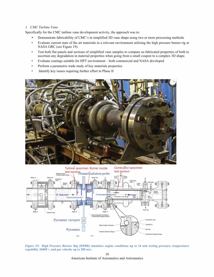
1. CMC Turbine Vane Specifically for the CMC turbine vane development activity, the approach was to:
• Demonstrate fabricability of CMC’s in simplified 3D vane shape using two or more processing methods • Evaluate current state of the art materials in a relevant environment utilizing the high pressure burner rig at
NASA GRC (see Figure 19). • Test both flat panels and sections of simplified vane samples to compare as-fabricated properties of both to
ascertain any degradation in material properties when going from a small coupon to a complex 3D shape. • Evaluate coatings suitable for HPT environment – both commercial and NASA developed • Perform a parametric trade study of key materials properties • Identify key issues requiring further effort in Phase II
Figure 19: High Pressure Burner Rig (HPBR) simulates engine conditions up to 16 atm testing pressure, temperature capability 2600F+, and gas velocity up to 200 m/s.
1
Planned radiation probe
Pyrometer
Pyrometer viewport
6” diameter 4” diameter
2.5” 2.5” 3.5”
Turbine test section Combustor test section
Turbine specimen test section
Combustor specimen test section
Burner nozzle
American Institute of Aeronautics and Astronautics 19
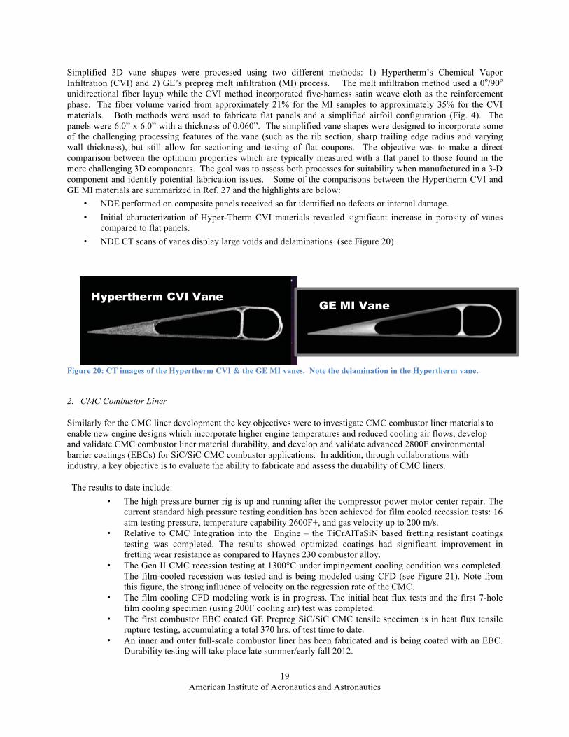
Simplified 3D vane shapes were processed using two different methods: 1) Hypertherm’s Chemical Vapor Infiltration (CVI) and 2) GE’s prepreg melt infiltration (MI) process. The melt infiltration method used a 0o/90o
unidirectional fiber layup while the CVI method incorporated five-harness satin weave cloth as the reinforcement phase. The fiber volume varied from approximately 21% for the MI samples to approximately 35% for the CVI materials. Both methods were used to fabricate flat panels and a simplified airfoil configuration (Fig. 4). The panels were 6.0” x 6.0” with a thickness of 0.060”. The simplified vane shapes were designed to incorporate some of the challenging processing features of the vane (such as the rib section, sharp trailing edge radius and varying wall thickness), but still allow for sectioning and testing of flat coupons. The objective was to make a direct comparison between the optimum properties which are typically measured with a flat panel to those found in the more challenging 3D components. The goal was to assess both processes for suitability when manufactured in a 3-D component and identify potential fabrication issues. Some of the comparisons between the Hypertherm CVI and GE MI materials are summarized in Ref. 27 and the highlights are below:
• NDE performed on composite panels received so far identified no defects or internal damage.• Initial characterization of Hyper-Therm CVI materials revealed significant increase in porosity of vanes
compared to flat panels. • NDE CT scans of vanes display large voids and delaminations (see Figure 20).
Figure 20: CT images of the Hypertherm CVI & the GE MI vanes. Note the delamination in the Hypertherm vane.
2. CMC Combustor Liner
Similarly for the CMC liner development the key objectives were to investigate CMC combustor liner materials to enable new engine designs which incorporate higher engine temperatures and reduced cooling air flows, develop and validate CMC combustor liner material durability, and develop and validate advanced 2800F environmental barrier coatings (EBCs) for SiC/SiC CMC combustor applications. In addition, through collaborations withindustry, a key objective is to evaluate the ability to fabricate and assess the durability of CMC liners.
The results to date include: • The high pressure burner rig is up and running after the compressor power motor center repair. The
current standard high pressure testing condition has been achieved for film cooled recession tests: 16 atm testing pressure, temperature capability 2600F+, and gas velocity up to 200 m/s.
• Relative to CMC Integration into the Engine – the TiCrAlTaSiN based fretting resistant coatings testing was completed. The results showed optimized coatings had significant improvement in fretting wear resistance as compared to Haynes 230 combustor alloy.
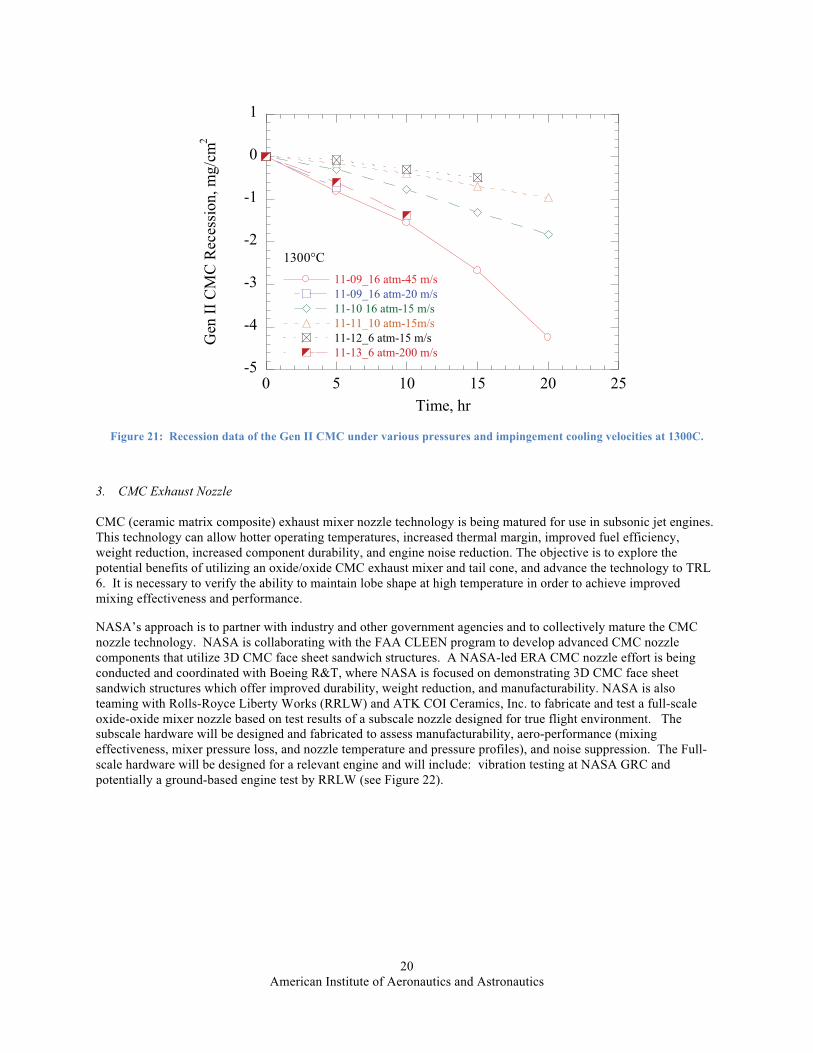
• The Gen II CMC recession testing at 1300°C under impingement cooling condition was completed. The film-cooled recession was tested and is being modeled using CFD (see Figure 21). Note from this figure, the strong influence of velocity on the regression rate of the CMC.
• The film cooling CFD modeling work is in progress. The initial heat flux tests and the first 7-holefilm cooling specimen (using 200F cooling air) test was completed.
• The first combustor EBC coated GE Prepreg SiC/SiC CMC tensile specimen is in heat flux tensile rupture testing, accumulating a total 370 hrs. of test time to date.
• An inner and outer full-scale combustor liner has been fabricated and is being coated with an EBC. Durability testing will take place late summer/early fall 2012.
Hypertherm CVI VaneGE MI Vane
American Institute of Aeronautics and Astronautics
20
Figure 21: Recession data of the Gen II CMC under various pressures and impingement cooling velocities at 1300C.
3. CMC Exhaust Nozzle
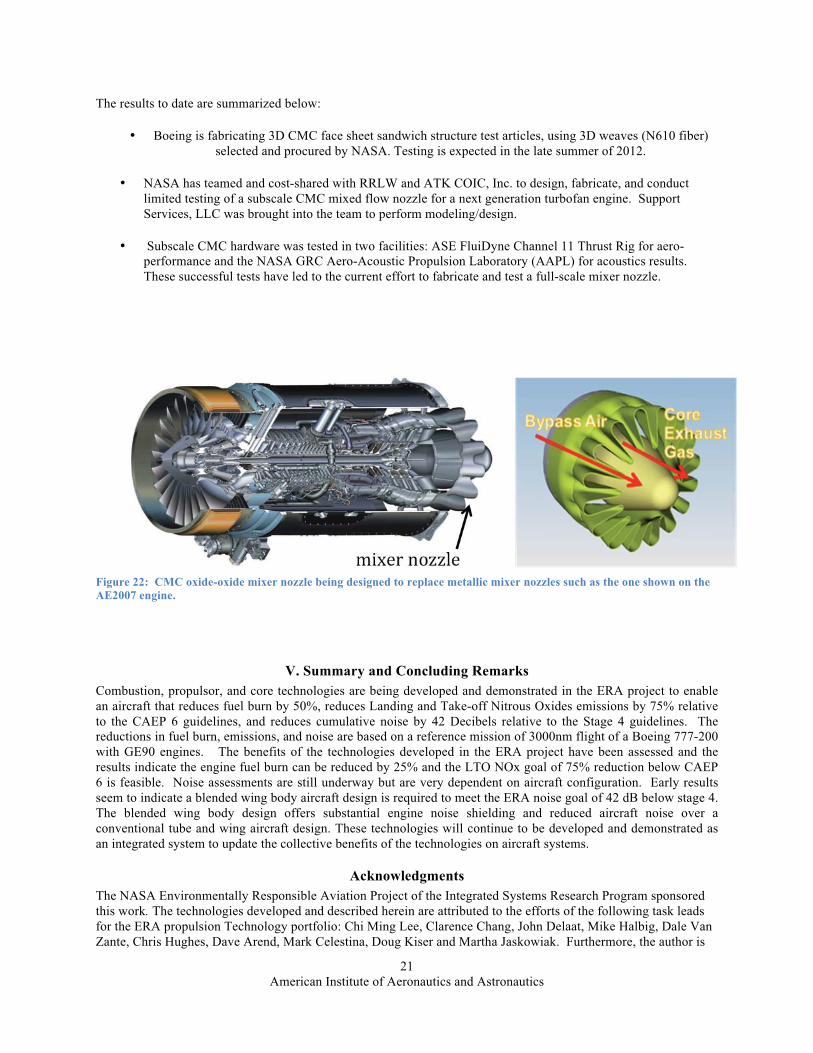
CMC (ceramic matrix composite) exhaust mixer nozzle technology is being matured for use in subsonic jet engines. This technology can allow hotter operating temperatures, increased thermal margin, improved fuel efficiency, weight reduction, increased component durability, and engine noise reduction. The objective is to explore the potential benefits of utilizing an oxide/oxide CMC exhaust mixer and tail cone, and advance the technology to TRL 6. It is necessary to verify the ability to maintain lobe shape at high temperature in order to achieve improved mixing effectiveness and performance.
NASA’s approach is to partner with industry and other government agencies and to collectively mature the CMC nozzle technology. NASA is collaborating with the FAA CLEEN program to develop advanced CMC nozzle components that utilize 3D CMC face sheet sandwich structures. A NASA-led ERA CMC nozzle effort is being conducted and coordinated with Boeing R&T, where NASA is focused on demonstrating 3D CMC face sheet sandwich structures which offer improved durability, weight reduction, and manufacturability. NASA is also teaming with Rolls-Royce Liberty Works (RRLW) and ATK COI Ceramics, Inc. to fabricate and test a full-scale oxide-oxide mixer nozzle based on test results of a subscale nozzle designed for true flight environment. The subscale hardware will be designed and fabricated to assess manufacturability, aero-performance (mixing effectiveness, mixer pressure loss, and nozzle temperature and pressure profiles), and noise suppression. The Full-scale hardware will be designed for a relevant engine and will include: vibration testing at NASA GRC and potentially a ground-based engine test by RRLW (see Figure 22).
-5
-4
-3
-2
-1
0
1
0 5 10 15 20 25
11-09_16 atm-45 m/s11-09_16 atm-20 m/s11-10 16 atm-15 m/s11-11_10 atm-15m/s11-12_6 atm-15 m/s11-13_6 atm-200 m/s
Gen
II C
MC
Rec
essi
on, m
g/cm
2
Time, hr
1300°C
American Institute of Aeronautics and Astronautics 21
The results to date are summarized below:
• Boeing is fabricating 3D CMC face sheet sandwich structure test articles, using 3D weaves (N610 fiber) selected and procured by NASA. Testing is expected in the late summer of 2012.
• NASA has teamed and cost-shared with RRLW and ATK COIC, Inc. to design, fabricate, and conduct limited testing of a subscale CMC mixed flow nozzle for a next generation turbofan engine. Support Services, LLC was brought into the team to perform modeling/design.
• Subscale CMC hardware was tested in two facilities: ASE FluiDyne Channel 11 Thrust Rig for aero-performance and the NASA GRC Aero-Acoustic Propulsion Laboratory (AAPL) for acoustics results. These successful tests have led to the current effort to fabricate and test a full-scale mixer nozzle.
Figure 22: CMC oxide-oxide mixer nozzle being designed to replace metallic mixer nozzles such as the one shown on the AE2007 engine.
V. Summary and Concluding Remarks Combustion, propulsor, and core technologies are being developed and demonstrated in the ERA project to enable an aircraft that reduces fuel burn by 50%, reduces Landing and Take-off Nitrous Oxides emissions by 75% relative to the CAEP 6 guidelines, and reduces cumulative noise by 42 Decibels relative to the Stage 4 guidelines. The reductions in fuel burn, emissions, and noise are based on a reference mission of 3000nm flight of a Boeing 777-200 with GE90 engines. The benefits of the technologies developed in the ERA project have been assessed and the results indicate the engine fuel burn can be reduced by 25% and the LTO NOx goal of 75% reduction below CAEP 6 is feasible. Noise assessments are still underway but are very dependent on aircraft configuration. Early results seem to indicate a blended wing body aircraft design is required to meet the ERA noise goal of 42 dB below stage 4. The blended wing body design offers substantial engine noise shielding and reduced aircraft noise over a conventional tube and wing aircraft design. These technologies will continue to be developed and demonstrated as an integrated system to update the collective benefits of the technologies on aircraft systems.
Acknowledgments The NASA Environmentally Responsible Aviation Project of the Integrated Systems Research Program sponsored this work. The technologies developed and described herein are attributed to the efforts of the following task leads for the ERA propulsion Technology portfolio: Chi Ming Lee, Clarence Chang, John Delaat, Mike Halbig, Dale Van Zante, Chris Hughes, Dave Arend, Mark Celestina, Doug Kiser and Martha Jaskowiak. Furthermore, the author is
American Institute of Aeronautics and Astronautics
22
appreciative to Scott Thomas for his thorough review and helpful discussions in the writing of this document. Additionally, the author wishes to extend his sincerest thanks to Dr. Fay Collier and the ERA Leadership team for their ERA project support and encouragement to promote this research to significantly reduce the impact of aviation on the environment by reducing the fuel burn, noise, and NOx emissions of future aircraft systems.
References
1Collier, Fayette, “Environmentally Responsible Aviation for Environmental Challenges Facing Aviation,” Report NF1676L-1123 (URL:http://ntrs.nasa.gov), GARDN, First Green Aviation Conference, Feb 2011. 2Jimenez, Hernando, Pfaender, Holger, and Mavris, Dimitri, “System-wide Fleet Assessment of NASA Environmentally Responsible Aviation (ERA) Technologies and Concepts for Fuel Burn and CO” AIAA-2011-6882, 11th AIAA Aviation Technology Integration, and Operations (ATIO) Conference, Virginia Beach, VA, Sep 20-22, 2011. 3Berton, J. and Guynn, M., “Multi-Objective Optimization of Turbofan Design Parameters for an Advanced Single-Aisle Transport, “AIAA paper 2010-9168, AIAA 10th Aviation Technology, Integration, and Operations (ATIO) Conference, Sept 2010. 4Guynn, M., Berton, Fisher, K., Haller, W., Tong, M., and Thurman, D., “Refined Exploration of Turbofan Design Options for an Advanced Single-Aisle Transport Aircraft,” NASA TM-2011-216883, Jan 2011. 5Tong, Michael T., Jones, Scott M., Haller, William J., Handschuh, Robert F., “Engine Conceptual Design Studies for a Hybrid Wing Body Aircraft,” NASA/ TM2009-215680, Nov 2009. 6Committee on Aviation Environmental Protection, Sixth Meeting, “Economic Analysis of NOx Emissions Stringency Options,” Technical Report CAEP/6-IP/13, International Civil Aviation Organization, Montreal, Canada, 2004. 7Garnier, V., “Aero Engines of the 21st Century: Evolution or Revolution?” Presented at the 20th ISABE Conference, Goteborg, Sep 15, 2011 8Van Zante, Dale, and Wojno, John, “The NASA/GE Open Rotor Research Campaign: ERA Diagnostics Test,” Ultra-High Bypass Propulsion Technology Panel, ASME Turbo Expo 2011, Vancouver, Canada, June 2011.
9Van Zante, Dale E., “ NASA/GE Collaboration on Open Rotors - High Speed Testing,” Report E -17798 (URL: http://ntrs.nasa.gov), Acoustics Technical Working Group, NASA Glenn Research Center, May 2011. 10Van Zante, Dale, “Reestablishing Open Rotor as an Option for Significant Fuel Burn Improvements,” Report HQ-STI-11-013 (URL: http://ntrs.nasa.gov), AIAA 48th Joint Propulsion Conference, Jul 2012 11Van Zante, Dale; Wojno, John; “The NASA/GE Open Rotor Research Campaign: ERA Diagnostics Test,” presentation at the ASME Turbo Expo 2011, Jun 2011. 12Van Zante, Dale; Gazzaniga, John; Elliott, David; and Woodward, Richard; “An Open Rotor Test Case: F31/A31 Historical Baseline Blade Set,” ISABE -2011-1310, Sep 2011. 13Van Zante, Dale, Wernet, Mark, “Tip Vortex and Wake Characteristics of a Counterrotating Open Rotor, AIAA 48th Joint Propulsion Conference, Jul 2012. 14Hughes,Christopher E., “Aircraft Engine Technology for Green Aviation to Reduce Fuel Burn,” paper AIAA-2011-3531-852, AIAA Atmospheric Space Environments Conference, Honolulu, HI, June 2011. 15Hughes, Christopher E., “NASA Collaborative Research on the Ultra High Bypass Engine Cycle and Potential Benefits for Noise, Performance and Emissions,” ISABE -2009-1274, 2009.
American Institute of Aeronautics and Astronautics
23
16 Hughes, Christopher E., NASA Glenn Research Center; Lord, Wesley, Pratt & Whitney; “NASA/Pratt & Whitney Collaborative Partnership Research in Ultra High Bypass Cycle Propulsion Concepts,” Report E-16905 (URL: http://ntrs.nasa.gov), Fundamental Aeronautics Program 2nd Annual Review, Oct 2008 17Hughes, Christopher, “Geared Turbofan Technology,” presentation at the NASA Green Aviation Summit, September 2010, URL: www.aeronautics.nasa.gov/pdf/hughes_green_aviation_summit.pdf. 18Hughes, Christopher, and Smith, Steven; “The Promise and Challenges of Ultra High Bypass Ratio Engine Technology and Integration,” Report HQ-STI-11-012 (URL: http://ntrs.nasa.gov), AIAA 49th Aerospace Sciences Meeting, Jan 2011. 19Hughes, C., and Edmane, E., “Overview of Recent Ultra High Bypass Engine Cycle -Based Scale Model Test Results,” presentation at the Fundamental Aeronautics Program 3rd Annual Review, Sep 2009. 20Arend, D.J., Generation After Next Propulsors: Robust Design for Embedded Engine Systems, SAE S-16 Committee Meeting Presentation, March 1-3, 2011, p. 13. 21Arend, D.J., Tillman, G., and O’Brien, W.F., “Generation After Next Propulsors Research: Robust Design for Embedded Engine Systems, AIAA 48th Joint Propulsion Conference, July 2012. 22Liou, Ming-Sing and Lee, Byung Joon, “ Minimizing Inlet Distortion for Hybrid Wing Body Aircraft,” Journal of Turbomachinery, Vol 134, May 2012 23Tong, M.T., “An Assessment of the impact of Emerging High-Temperature Materials on Engine Cycle Performance, GT2010-22361, ASME TURBO EXPO 2012, Jun 2010. 24Celestina, Mark L, Fabian, John C., and Kulkarni, Sameer, “NASA Environmentally responsible Aviation High Overall Pressure Ratio Compressor Research – Pre-Test CFD,”AIAA 48th Joint Propulsion Conference, Jul 2012. 25DiCarlo, J.A. et al, “High Performance SiC/SiC Ceramic Composite Systems Developed for 1315C (2400F) Engine Components, NASA TM-2004-212729, 2004. Pp12-13. 26Zhu, D, Miller, R.A., Fox, D.S., “Thermal and Environmental Barrier Coating Development for Advanced Propulsion Engine Systems,” NASA TM-2008-215040. 27Jaskowiak, Martha, DiCarlo, James, Bhatt, Ram, Zhu, Dongming, Phillips, Ronald, Rauser, Richard, and Gorican, Daniel. “SiC/SiC Composites Evaluated for Turbine Vane Applications Under NASA’s ERA Program,” Proceedings of the 36th Annual Conference on Composites, Materials, and Structures (U.S. Citizens Only / ITAR-Restricted Sessions), January 23-26, 2012, in Cocoa Beach / Cape Canaveral, Florida.