Embed Size (px)
Citation preview
1
Mobile Climbing Tower Manual Rev. 03/11
Operation and Owner’s Manual
For
Spectrum Sports Intl
MOBILE Climbing Towers
Important Safety Information Inside
Attention! Read this manual before operating
the product.
2
Mobile Climbing Tower Manual Rev. 03/11
INTRODUCTION
WARNING! Spectrum Sports Intl will not warranty or stand behind any Mobile Climbing
Tower and/or Auto-Belay safety system that we have manufactured that does not use genuine and/or authorized replacement parts and/or cable. Any work and/or service that is performed on any Spectrum Sports Intl Auto-Belay safety systems that is not performed by an authorized Spectrum Sports Intl employee, voids any and all claims to any manufacturer’s liability.
Read and understand this manual before installing and/or operating the product.
CLIMBING can cause Serious injury or Death, if failure to comply with the information in this manual.
3785 N. HWY 91 ǀ Hyde Park ǀ Utah 84318ǀ 888.563.0163
3
Mobile Climbing Tower Manual Rev. 03/11
Climbing Tower Mobile Operations/Owners Manual
Products: ClimbNDangle®, Drop A Rock®, Grip A Rock®, RidgeLine®, ClimbNChallenge®, and Coconut Tree Climb®
Table of Contents:
Change of Owner/operator Form……………………………………………………………… Page 5 Welcome 6 Notice of Copyright 6 Revision 7 Receipt and Acknowledgment 7 Product Overview 8 Product Identification 9 Manual Overview 10 THE AUTO-BELAY SAFETY SYSTEM 11 Certifications/ Standards 12 Product Specs: AB-32 13
AB-40, AB-75 14 Auto-Belay Sticker Package 15 How the Auto-Belay Safety System Works 16 INSPECTIONS 17 A) Daily B) Weekly C) 3 Months D) 12 Months Wear Items 24 Air Pressure 24 Hydraulic Fluid Specs 24 CABLE INSPECTION 25 Cable Inspection Techniques 26 ASME Code 29 Cable Replacement Options 29 OPERATING/USING THE AUTO-BELAY 30 CLIMBING OPERATIONS 32 Required Personnel for Operations 33 Climbing Zones 34 Rules and Safety Tips 35 Emergency Climber Recovery 35 MOBILE CLIMBING TOWER INSPECTIONS 37 Inspections 38 Non-Destructive Examinations (NDE) 39 TRANSPORTATION CHECKLIST 40 Pre-Trip Checklist 41 Safety and Warning Notifications on Trailers 43
4
Mobile Climbing Tower Manual Rev. 03/11
PRODUCT “SET-UP” INSTRUCTIONS 44 1. Locate “Set-Up” Area 45 2. Observe Overhead Obstacles 45 3. Park Climbing Tower in Safe Area 46 4. Unhook Trailer from Tow Vehicle 46 5. Level Trailer 46 6. Remove Travel Safety Strap 47 7. Prep Climbing Tower 47 8. Remote Pendant 48 9. Raise Climbing Tower 48 10. Level Climbing Tower onto Ground 49 11. Trailer Options 50 12. Auto-Belay Prep 51 PRODUCT “TAKE-DOWN” INSTRUCTIONS 52 1. Auto- Belay Prep 53 2. Raise Tower off the Ground 53 3. Remote Pendant 53 4. Lower Climbing Tower onto Trailer 54 5. Secure Travel Safety Strap 54 6. Remove Any Banners, Etc. 54 7. Store Misc Items & Safety Climbing Gear 54 8. Lower Trailer to Ground 54 9. Prep Trailer for Transport 55 10. Pre-Trip Check List 55 11. Connecting the Trailer to the Tow Vehicle 56 12. Transporting the Climbing Tower 56 MAINTENANCE 58 Cleaning 59 Product Storage 60 WARRANTY 61 Conclusion 66 TROUBLE SHOOTING 67 APPENDICES 70 Appendix A: Accessories & Parts Order Forms 71 Appendix B: Changing an Auto-Belay Cylinder 73 Appendix C: Oil Collection Kit Installation 74 Appendix D: Seal Kit Replacement 75 Appendix E: Cable Replacement 76 Appendix F: Wiring Schematic for Breakaway Switch 78 Appendix G: Wiring Diagram for Electrical Connectors 79 Appendix H: ASTM Standard Guide for Device Related Injuries 80 Appendix I: Climbing Tower Horn Wiring Diagram 82 Appendix J: SSI Quick-Harness Brochure 83
5
Mobile Climbing Tower Manual Rev. 03/11
Change of owner/operator form
Original Owner:
Company Name: _________________________________________________________________
Contact name (s): _________________________________________________________________
Bill to Address: _________________________________________________________________
City: ______________________________ State: ______________________ Zip: _________________
Phone: ____________________ Alt. Phone: _______________________ Fax: ________________
Former Location: _______________________________________________________________________
City: ______________________________ State: ______________________ Zip: _________________
Date Sold: _______________________________
New Owner/Operator Information:
Company Name: ____________________________________________________________________
Contact name (s): ____________________________________________________________________
Bill to Address: ____________________________________________________________________
City: ______________________________ State: ______________________ Zip: _________________
Phone: ____________________ Alt. Phone: _______________________ Fax: __________________
Current Location: ____________________________________________________________________
City: ______________________________ State: ______________________ Zip: _________________
Product Information:
GAR, DAR, CND, RL, CTC, CNC
Mobile/Stationary 20’ 22’ 24’ 28’ 30’ 32’ Custom: __________________________
Serial # ______________________________
VIN # _______________________________
Year: ________________________________
*Please mail or fax to:
3785 N. Hwy. 91
Hyde Park, UT 84318
Fax: (435) 792-388
6
Mobile Climbing Tower Manual Rev. 03/11
Welcome
Thank you for purchasing a quality built climbing product from Spectrum Sports Intl. We take pride in our products and believe that we build the best products in our industry. Our philosophy is centered on a commitment to excellence in meeting the needs of our customers, providing a quality product that is safe, exciting, and profitable. We encourage you to likewise develop a standard of quality and service that makes you the leader in your market.
Our part in making our team successful is:
Commitment to proper, effective and profitable design. Third Party Engineering on all of our products. Manufacturing to “ASTM F-24” safety standards for the amusement industry. Testing designs before the sale. Maximum customer through-put generating high profits. Building quality products, means a lower cost of ownership. Experience and Leadership in the industry. All assembly is done in-house, which provides for exceptional Quality Control.
Your part in building a successful business using Spectrum Sports Intl products is:
Commitment to safe operation Consistent inspection for proper maintenance Effective and active marketing and promotion Use Spectrum Sports Intl certified replacement parts
Always remember to follow all safety guidelines and practice safety and caution while operating your product.
Copyright© Spectrum Sports Intl
Reproduction or translation of any part of this work beyond that permitted by Section 107 or 108 of the 1976 United States Copyright Act without
permission of the copyright owner is unlawful. Requests for permission or further information should be addressed to Spectrum Sports Intl.
Serious injury or Death may result if failure to comply with the information in this manual.
3785 N. HWY 91 ǀ Hyde Park ǀ Utah 84318ǀ 888.563.0163
7
Mobile Climbing Tower Manual Rev. 03/11
Revision Spectrum Sports Intl may make periodic additions, deletions, and modifications to this manual. These updates will, in the judgment of SPECTRUM SPORTS INTL, add to the quality of services offered. This manual must be kept up to date, and should reflect all updates currently in use.
Please check the web site for updates and/or safety issues regarding your Climbing Tower & Auto-Belay Safety System www.spectrumsports.com or www.auto-belay.com
Receipt & Acknowledgment
This Owner/Operations Manual is an important document intended to help you become acquainted with the Climbing towers and the Auto-Belay safety systems.
Please read the following statement; respond to Spectrum Sports Intl in writing with any questions or if the intent of this document is unclear. You should not operate the products mentioned in this manual if you do not fully understand how to operate them safely!
“As an owner, I have received and read my copy of the Climbing Tower Owner’s Manual. I understand that the information outlined in this manual is subject to change at the sole discretion of Spectrum Sports Intl at any time. It is further understood that as an owner of the Climbing Tower, I have the responsibility to ensure that the correct and latest version of the manual is being used.
As an owner of the Climbing Tower or authorized representative, it is my responsibility to keep this manual up-to-date with any changes that are made by Spectrum Sports Intl. In addition, if there is anything about the product and/or this manual that is unclear or not understood, it is my responsibility to seek clarification and not use the product until the issue is understood.
Unless informed in writing, Spectrum Sports Intl assumes that the customer understands the Climbing Tower product and that there are no questions regarding the product and/or the contents of this document, use of the product or how to operate this product.
It is the customer’s sole responsibility to clarify any question or concern with Spectrum Sports Intl before use and/or operation.
8
Mobile Climbing Tower Manual Rev. 03/11
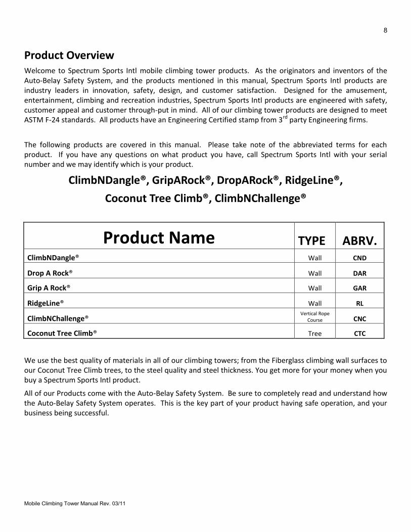
Product Overview Welcome to Spectrum Sports Intl mobile climbing tower products. As the originators and inventors of the Auto-Belay Safety System, and the products mentioned in this manual, Spectrum Sports Intl products are industry leaders in innovation, safety, design, and customer satisfaction. Designed for the amusement, entertainment, climbing and recreation industries, Spectrum Sports Intl products are engineered with safety, customer appeal and customer through-put in mind. All of our climbing tower products are designed to meet ASTM F-24 standards. All products have an Engineering Certified stamp from 3rd party Engineering firms.
The following products are covered in this manual. Please take note of the abbreviated terms for each product. If you have any questions on what product you have, call Spectrum Sports Intl with your serial number and we may identify which is your product.
ClimbNDangle®, GripARock®, DropARock®, RidgeLine®,
Coconut Tree Climb®, ClimbNChallenge®
Product Name TYPE ABRV. ClimbNDangle® Wall CND
Drop A Rock® Wall DAR
Grip A Rock® Wall GAR
RidgeLine® Wall RL
ClimbNChallenge® Vertical Rope
Course CNC
Coconut Tree Climb® Tree CTC
We use the best quality of materials in all of our climbing towers; from the Fiberglass climbing wall surfaces to our Coconut Tree Climb trees, to the steel quality and steel thickness. You get more for your money when you buy a Spectrum Sports Intl product.
All of our Products come with the Auto-Belay Safety System. Be sure to completely read and understand how the Auto-Belay Safety System operates. This is the key part of your product having safe operation, and your business being successful.
9
Mobile Climbing Tower Manual Rev. 03/11
Product Identification
GripARock®, DropARock®, ClimbNDangle®, RidgeLine®
Coconut Tree Climb®, ClimbNChallenge®
Product Name: _____________________________________________________
Model: ________________ Date Manufactured: _________________
Specialty Items: _____________________________________________
Serial Number: ___________
Passenger Capacity: _____Number of Auto-Belay Safety Systems:_____
Company Name: ____________________________________________
Customer Name: ____________________________________________
Phone Number: _____________________________________________
Address: ___________________________________________________
___________________________________________________
3785 N. HWY 91 ǀ Hyde Park ǀ Utah 84318ǀ 888.563.0163
10
Mobile Climbing Tower Manual Rev. 03/11
Manual Overview This manual is an introduction to the climbing tower and its operation. The purpose of this manual is to provide a compilation of information that will assist you in proper and safe operation. The philosophy of Spectrum Sports Intl is centered on a commitment to excellence in meeting the needs of its customers and associates by providing them with the enclosed information. This manual is designed to provide the product owner with the information, tips, and techniques that will help the owner and employees operate the climbing tower as effectively and safely as possible. This manual is no way a total representation of all facts. Safe operation of this product is the sole responsibility of the wall owner/operator. Good and reasonable judgment must be used when traveling, promoting and/or operating the product.
ACCIDENT REPORTING Spectrum Sports Intl requires that any and all accidents are reported within 48hrs from the time of the accident. We need the name of the injured, place of the accident, incident report, the route the accident occurred on, a description of the accident and the proposed product failure, the employee’s name, daily inspection report/checklist, and date the employee was trained on the use of the product. More info may be required at a later time. Email or fax a report to: [email protected] or 435-792-3884
Engineering Approval Our products have been designed and reviewed by 3rd party engineers that stand behind the product design. If it is necessary that you receive a copy of the engineering analysis, SSI will provide a copy contingent upon the signing of a “non-disclosure/non-compete agreement” and a small fee. Please call Spectrum Sports Intl for details.
CUSTOMER IS RESPONSIBLE FOR FINDING WHAT CURRENT CODES ARE REQUIRED TO OPERATE PRODUCT WITHIN THEIR STATE.

11
Mobile Climbing Tower Manual Rev. 03/11
THE AUTO-BELAY
SAFETY SYSTEM

12
Mobile Climbing Tower Manual Rev. 03/11
The AUTO-BELAY SAFETY SYSTEM
Product Manual Overview
This manual is an introduction to the AUTO-BELAY SAFETY SYSTEM and its operation. The purpose of this manual is to provide a compilation of information that will assist you in proper and safe operation. This manual is designed to aid in educating you and your associates.
Certifications / Standards Spectrum Sports Intl has the following certifications or meet/exceed the following industry standards.
ASTM Requirements for Owner/Operator Responsibilities: “Owner/operators of amusement rides or devices shall have an inspection program consistent with the inspections outlined in Practice F 853 & Practice F 770. Inspection documents deemed appropriate by the owner/operator to be maintained in the ride file shall be filed in accordance with the procedures outlined in Practice F 770 and Practice F 853. The owner/operator of an amusement ride or device shall promptly notify the manufacturer of an incident, failure, or malfunction which, in his judgment, seriously affects the continued proper operation of the ride or device and is information of which the manufacturer should be aware.”
(Ref: ASTM International Standards on Amusement Rides and Devices: 7th
Edition, Sections: 5.2.1-5.2.3)

13
Mobile Climbing Tower Manual Rev. 03/11
PRODUCT SPECS
Height limits for each Auto-Belay Safety System
Product 0'- 32' 0'- 40' 0'- 75'
AB32
AB40
AB75
AB32 Spec: GENERATION 4
Size: 9’3” Long, 12” wide and 17” deep
Weight: 180 lbs
Mounting Height: Typically ground level, remote location okay
Climbing Range: 10’-33’
Maximum climbers weight: 250 lbs
Color: Black powder coated finish
Design: Dual cylinder-open design
Body Material: Steel
Cylinders: 39” X 1 ½” 2500 PSI (Qty 2)
Weather proof hydraulic breather caps (Qty2)
Pulleys: 6” sealed bearing, nylon (Qty 9) for ¼” cable
Oil: ISO 32
Upper Pulley Cart: 8 sealed bearing
Air Pressure: 85 – 95 PSI operations pressure
Hoses: 2000 PSI
Fittings: #10, o-ring with face seals
Hardware: grade 8 on pulleys, grade 5 on assemblies
Oil Filtration System: Yes, inline screen
Oil Containment System: available at additional cost
Oil Site Glass: mounted for clear inspections
Pressure Gauge: 0- 150 PSI
Breather Cap: low profile
1” quick connections pins: on both Auto-Belay cylinders
Easy 4 bolt mounting system
14
Mobile Climbing Tower Manual Rev. 03/11
AB40 Spec: GENERATION 4
Size: 9’3” Long, 14” wide and 17” deep
Weight: 180 lbs
Mounting Height: Typically ground level, remote location okay
Climbing Range: 10’-40’
Maximum climbers weight: 250 lbs
Color: Black powder coated finish
Design: Dual cylinder-open design
Body Material: Steel
Cylinders: 39” X 1 ½” 2500 PSI (Qty 2)
Weather proof hydraulic breather caps (Qty2)
Pulleys: 6” sealed bearing, nylon (Qty 9) for ¼” cable
Oil: ISO 32
Upper Pulley Cart: 8 sealed bearing
Air Pressure: 95 – 105 PSI operations pressure
Hoses: 2000 PSI
Fittings: #10, o-ring with face seals
Hardware: grade 8 on pulleys, grade 5 on assemblies
Oil Filtration System: Yes, inline screen
Oil Containment System: available at additional cost
Oil Site Glass: mounted for clear inspections
Pressure Gauge: 0- 150 PSI
Breather Cap: low profile
1” quick connections pins: on both Auto-Belay cylinders
Easy 4 bolt mounting system
AB75 Spec: GENERATION 4
Size: 9’3” Long, 24” wide and 17” deep
Weight: 370 lbs
Mounting Height: ground level, remote location okay
Climbing Range: 10’- 75’
Maximum climbers weight: 250 lbs
Color: Black powder coated finish
Design: Dual cylinder-open design
Body Material: Steel
Cylinders: 39” X 1 ½” 2500 PSI (Qty 2)
Pulleys: 6” sealed bearing, nylon, fits 10.5 mm rope (Qty 9)
Oil: ISO 32 w/blue dye
Upper Pulley Cart: 8 sealed bearing
15
Mobile Climbing Tower Manual Rev. 03/11
Air Pressure: 105 – 110 PSI operations pressure (depends on routing)
Hoses: 2000 PSI
Fittings: #10, o-ring with face seals
Hardware: grade 8 on pulleys, grade 5 on assemblies
Oil Filtration System: Yes, inline screen
Oil Containment System: available at additional cost
Oil Site Glass: mounted for clear inspections
Pressure Gauge: 0- 160 PSI
Breather Cap: low profile
1” quick connections pins: on both Auto-Belay cylinders
Easy 4 bolt mounting system
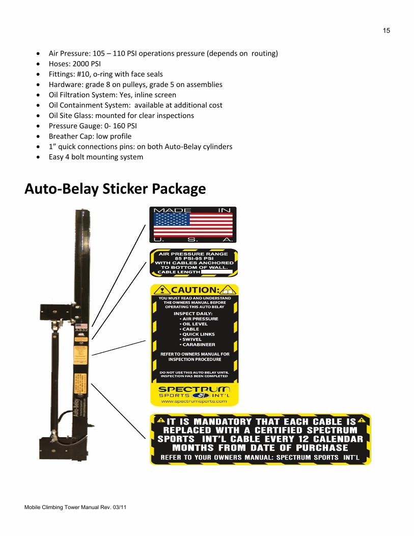
Auto-Belay Sticker Package
16
Mobile Climbing Tower Manual Rev. 03/11
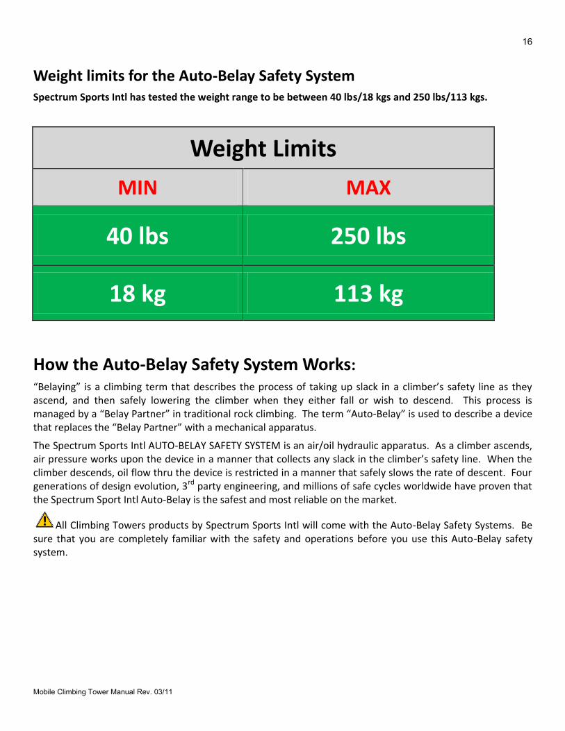
Weight limits for the Auto-Belay Safety System Spectrum Sports Intl has tested the weight range to be between 40 lbs/18 kgs and 250 lbs/113 kgs.
Weight Limits
MIN MAX
40 lbs 250 lbs
18 kg 113 kg
How the Auto-Belay Safety System Works: “Belaying” is a climbing term that describes the process of taking up slack in a climber’s safety line as they ascend, and then safely lowering the climber when they either fall or wish to descend. This process is managed by a “Belay Partner” in traditional rock climbing. The term “Auto-Belay” is used to describe a device that replaces the “Belay Partner” with a mechanical apparatus.
The Spectrum Sports Intl AUTO-BELAY SAFETY SYSTEM is an air/oil hydraulic apparatus. As a climber ascends, air pressure works upon the device in a manner that collects any slack in the climber’s safety line. When the climber descends, oil flow thru the device is restricted in a manner that safely slows the rate of descent. Four generations of design evolution, 3rd party engineering, and millions of safe cycles worldwide have proven that the Spectrum Sport Intl Auto-Belay is the safest and most reliable on the market.
All Climbing Towers products by Spectrum Sports Intl will come with the Auto-Belay Safety Systems. Be sure that you are completely familiar with the safety and operations before you use this Auto-Belay safety system.

17
Mobile Climbing Tower Manual Rev. 03/11
INSPECTIONS
18
Mobile Climbing Tower Manual Rev. 03/11
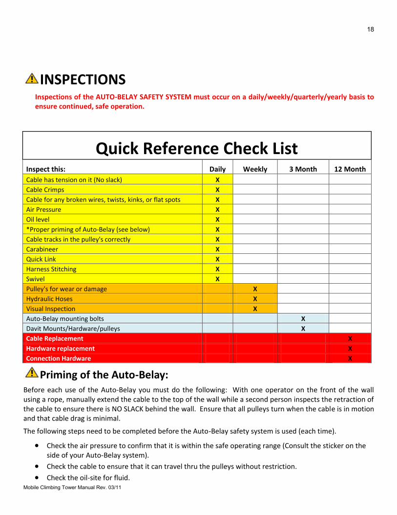
INSPECTIONS
Inspections of the AUTO-BELAY SAFETY SYSTEM must occur on a daily/weekly/quarterly/yearly basis to ensure continued, safe operation.
Quick Reference Check List Inspect this: Daily Weekly 3 Month 12 Month
Cable has tension on it (No slack) X
Cable Crimps X Cable for any broken wires, twists, kinks, or flat spots X
Air Pressure X
Oil level X
*Proper priming of Auto-Belay (see below) X Cable tracks in the pulley's correctly X
Carabineer X
Quick Link X
Harness Stitching X
Swivel X
Pulley's for wear or damage X
Hydraulic Hoses X
Visual Inspection X
Auto-Belay mounting bolts X
Davit Mounts/Hardware/pulleys X
Cable Replacement X
Hardware replacement X
Connection Hardware X
Priming of the Auto-Belay: Before each use of the Auto-Belay you must do the following: With one operator on the front of the wall using a rope, manually extend the cable to the top of the wall while a second person inspects the retraction of the cable to ensure there is NO SLACK behind the wall. Ensure that all pulleys turn when the cable is in motion and that cable drag is minimal.
The following steps need to be completed before the Auto-Belay safety system is used (each time).
Check the air pressure to confirm that it is within the safe operating range (Consult the sticker on the side of your Auto-Belay system).
Check the cable to ensure that it can travel thru the pulleys without restriction. Check the oil-site for fluid.
19
Mobile Climbing Tower Manual Rev. 03/11
Pull on the cable (front side of the wall) and make sure that the cable retracts itself, do this several times, in the meantime making sure that the cable has an elastic feel.
While standing on the front side of the wall (the side that is for climbing), hold on to the cable, raise it above your head, then pull it to the ground (priming the Auto-Belay safety system). Do this multiple times.
Once you have primed the system, hook onto the Auto-Belay safety system (wearing a climbing harness) and climb up 5’, then let go, allowing the Auto-Belay safety system to lower you to the ground.
Continue to climb up the wall 5’ at a time, and allow the system to lower you down. Repeat until you have reached the top.
Once you have ensured that the Auto-Belay Safety System is operating properly you may now allow clients to climb.
Remember, fluid levels should be checked when all Auto-Belay routes are anchored to the bottom of the wall (meaning that the carabineer-end of the cable must be in the “start climbing” position). If any questions, please call SPECTRUM SPORTS INTL.
For proper and safe Auto-Belay function, it is important that the Auto-Belay is properly pressurized.
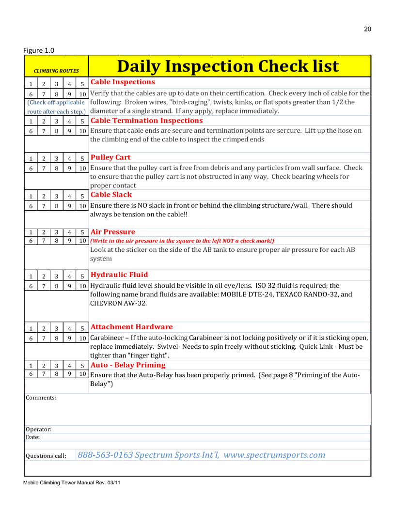
Daily Inspections: Please note that these inspection guidelines are a minimum. Take caution
and ensure that any and all working parts and safety related products are thoroughly inspected and that all bolts are secure before use. As a means of properly maintaining the AUTO-BELAY SAFETY SYSTEM and ensuring proper safety for the climber, a daily inspection is required. The following routine should be adhered to daily. Figure 1.0 is a sample. You may download an actual inspection sheet from the website www.spectrumsports.com.
Weekly Inspections: Weekly inspections are intended to be more in-depth than daily
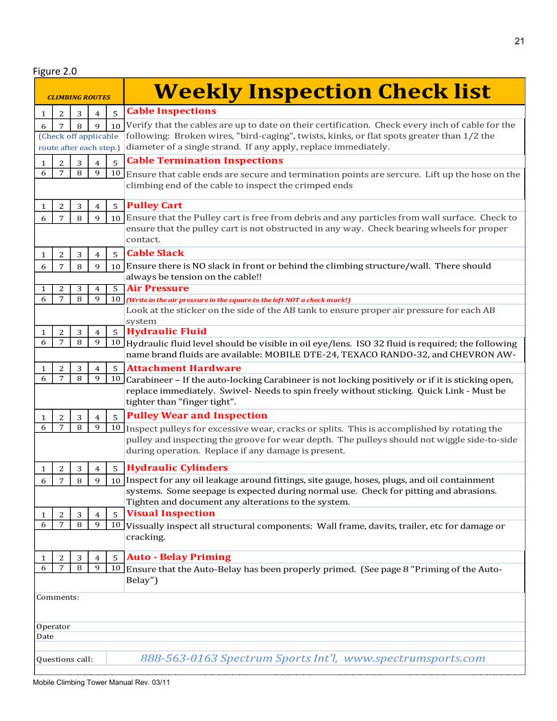
inspections. On the Auto-Belay, no component will fail without first revealing warning signs due to wear or damage. In conjunction with the daily inspections, the weekly inspections should be sufficient to find any potential problem well before failure becomes imminent. Figure 2.0 is a sample. You may download an actual inspection sheet from the website www.spectrumsports.com.
3 Month Inspections: 3 month inspections are intended to be more in-depth than Weekly
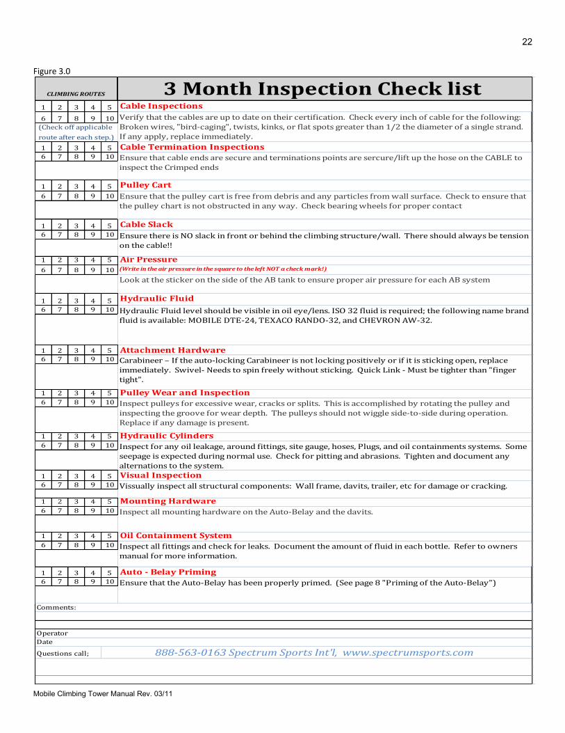
inspections. On the Auto-Belay, no component will fail without first revealing warning signs due to wear or damage. In conjunction with the weekly inspections, the 3 month inspections should be sufficient to find any potential problem well before failure becomes imminent. Figure 3.0 is a sample. You may download an actual inspection sheet from the website www.spectrumsports.com.
12 Month Inspections: 12 month inspections are intended to be more in-depth than 3
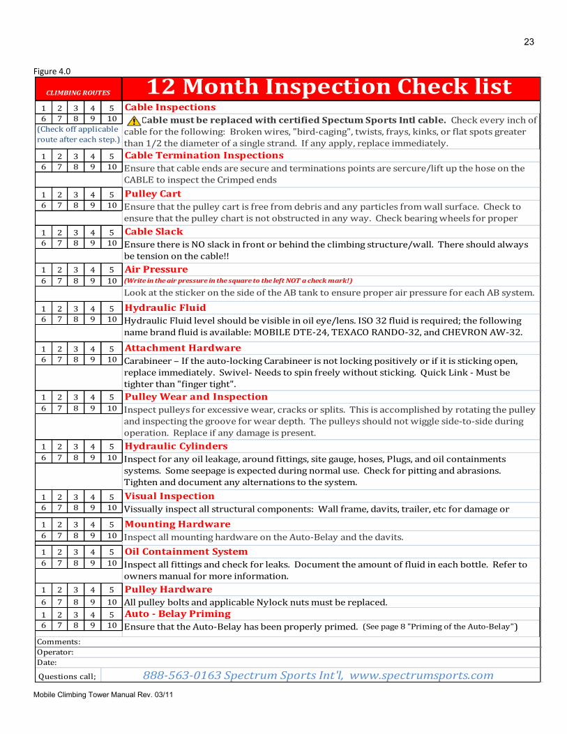
month inspections, and include mandatory parts’ replacement. On the Auto-Belay, no component will fail without first revealing warning signs due to wear or damage. In conjunction with the 3 month inspections, the 12 month inspections should be sufficient to find any potential problem well before failure becomes imminent. Figure 4.0 is a sample. You may download an actual inspection sheet from the website www.spectrumsports.com.
20
Mobile Climbing Tower Manual Rev. 03/11
Figure 1.0
1 2 3 4 5
6 7 8 9 10
1 2 3 4 5
6 7 8 9 10
1 2 3 4 5
6 7 8 9 10
1 2 3 4 5
6 7 8 9 10
1 2 3 4 5
6 7 8 9 10
1 2 3 4 5
6 7 8 9 10
1 2 3 4 5
6 7 8 9 10
1 2 3 4 5
6 7 8 9 10
Questions call;
CLIMBING ROUTES Daily Inspection Check list
Air Pressure
Operator:
Date:
Attachment Hardware
Ensure that cable ends are secure and termination points are sercure. Lift up the hose on
the climbing end of the cable to inspect the crimped ends
Ensure that the pulley cart is free from debris and any particles from wall surface. Check
to ensure that the pulley cart is not obstructed in any way. Check bearing wheels for
proper contact
Cable Inspections
Cable Termination Inspections
Comments:
Verify that the cables are up to date on their certification. Check every inch of cable for the
following: Broken wires, "bird-caging", twists, kinks, or flat spots greater than 1/2 the
diameter of a single strand. If any apply, replace immediately.
Pulley Cart
Carabineer – If the auto-locking Carabineer is not locking positively or if it is sticking open,
replace immediately. Swivel- Needs to spin freely without sticking. Quick Link - Must be
tighter than "finger tight".
(Write in the air pressure in the square to the left NOT a check mark!)
Ensure there is NO slack in front or behind the climbing structure/wall. There should
always be tension on the cable!!
Cable Slack
Hydraulic Fluid
888-563-0163 Spectrum Sports Int'l, www.spectrumsports.com
Auto - Belay Priming
Ensure that the Auto-Belay has been properly primed. (See page 8 "Priming of the Auto-
Belay")
(Check off applicable
route after each step.)
Look at the sticker on the side of the AB tank to ensure proper air pressure for each AB
system
Hydraulic fluid level should be visible in oil eye/lens. ISO 32 fluid is required; the
following name brand fluids are available: MOBILE DTE-24, TEXACO RANDO-32, and
CHEVRON AW-32.
21
Mobile Climbing Tower Manual Rev. 03/11
Figure 2.0
1 2 3 4 5
6 7 8 9 10
1 2 3 4 5
6 7 8 9 10
1 2 3 4 5
6 7 8 9 10
1 2 3 4 5
6 7 8 9 10
1 2 3 4 5
6 7 8 9 10
1 2 3 4 5
6 7 8 9 10
1 2 3 4 5
6 7 8 9 10
1 2 3 4 5
6 7 8 9 10
1 2 3 4 5
6 7 8 9 10
1 2 3 4 5
6 7 8 9 10
1 2 3 4 5
6 7 8 9 10
Questions call: 888-563-0163 Spectrum Sports Int'l, www.spectrumsports.com
Pulley Cart
CLIMBING ROUTES Weekly Inspection Check list
Operator
Date
Verify that the cables are up to date on their certification. Check every inch of cable for the
following: Broken wires, "bird-caging", twists, kinks, or flat spots greater than 1/2 the
diameter of a single strand. If any apply, replace immediately.
Ensure that cable ends are secure and termination points are sercure. Lift up the hose on the
climbing end of the cable to inspect the crimped ends
Cable Inspections
Cable Termination Inspections
Cable Slack
Inspect for any oil leakage around fittings, site gauge, hoses, plugs, and oil containment
systems. Some seepage is expected during normal use. Check for pitting and abrasions.
Tighten and document any alterations to the system.
Hydraulic Cylinders
(Write in the air pressure in the square to the left NOT a check mark!)
Look at the sticker on the side of the AB tank to ensure proper air pressure for each AB
system
Comments:
Ensure that the Pulley cart is free from debris and any particles from wall surface. Check to
ensure that the pulley cart is not obstructed in any way. Check bearing wheels for proper
contact.
Hydraulic Fluid
Attachment Hardware
Inspect pulleys for excessive wear, cracks or splits. This is accomplished by rotating the
pulley and inspecting the groove for wear depth. The pulleys should not wiggle side-to-side
during operation. Replace if any damage is present.
Pulley Wear and Inspection
Air Pressure
Ensure that the Auto-Belay has been properly primed. (See page 8 "Priming of the Auto-
Belay")
Ensure there is NO slack in front or behind the climbing structure/wall. There should
always be tension on the cable!!
Hydraulic fluid level should be visible in oil eye/lens. ISO 32 fluid is required; the following
name brand fluids are available: MOBILE DTE-24, TEXACO RANDO-32, and CHEVRON AW-
32.
Carabineer – If the auto-locking Carabineer is not locking positively or if it is sticking open,
replace immediately. Swivel- Needs to spin freely without sticking. Quick Link - Must be
tighter than "finger tight".
(Check off applicable
route after each step.)
Visual Inspection
Vissually inspect all structural components: Wall frame, davits, trailer, etc for damage or
cracking.
Auto - Belay Priming
22
Mobile Climbing Tower Manual Rev. 03/11
Figure 3.0
1 2 3 4 5
6 7 8 9 10
1 2 3 4 5
6 7 8 9 10
1 2 3 4 5
6 7 8 9 10
1 2 3 4 5
6 7 8 9 10
1 2 3 4 5
6 7 8 9 10
1 2 3 4 5
6 7 8 9 10
1 2 3 4 5
6 7 8 9 10
1 2 3 4 5
6 7 8 9 10
1 2 3 4 5
6 7 8 9 10
1 2 3 4 5
6 7 8 9 10
1 2 3 4 5
6 7 8 9 10
1 2 3 4 5
6 7 8 9 10
1 2 3 4 5
6 7 8 9 10
Questions call;
Ensure there is NO slack in front or behind the climbing structure/wall. There should always be tension
on the cable!!
Comments:
Operator
CLIMBING ROUTES 3 Month Inspection Check list
Verify that the cables are up to date on their certification. Check every inch of cable for the following:
Broken wires, "bird-caging", twists, kinks, or flat spots greater than 1/2 the diameter of a single strand.
If any apply, replace immediately.
Hydraulic Fluid level should be visible in oil eye/lens. ISO 32 fluid is required; the following name brand
fluid is available: MOBILE DTE-24, TEXACO RANDO-32, and CHEVRON AW-32.
Carabineer – If the auto-locking Carabineer is not locking positively or if it is sticking open, replace
immediately. Swivel- Needs to spin freely without sticking. Quick Link - Must be tighter than "finger
tight".
(Write in the air pressure in the square to the left NOT a check mark!)
Cable Inspections
Ensure that cable ends are secure and terminations points are sercure/lift up the hose on the CABLE to
inspect the Crimped ends
Pulley Cart
Ensure that the pulley cart is free from debris and any particles from wall surface. Check to ensure that
the pulley chart is not obstructed in any way. Check bearing wheels for proper contact
Cable Termination Inspections
Inspect pulleys for excessive wear, cracks or splits. This is accomplished by rotating the pulley and
inspecting the groove for wear depth. The pulleys should not wiggle side-to-side during operation.
Replace if any damage is present.
Pulley Wear and Inspection
Inspect for any oil leakage, around fittings, site gauge, hoses, Plugs, and oil containments systems. Some
seepage is expected during normal use. Check for pitting and abrasions. Tighten and document any
alternations to the system.
Cable Slack
Air Pressure
Look at the sticker on the side of the AB tank to ensure proper air pressure for each AB system
Ensure that the Auto-Belay has been properly primed. (See page 8 "Priming of the Auto-Belay")
Date
888-563-0163 Spectrum Sports Int'l, www.spectrumsports.com
Hydraulic Cylinders
Mounting Hardware
Inspect all mounting hardware on the Auto-Belay and the davits.
Inspect all fittings and check for leaks. Document the amount of fluid in each bottle. Refer to owners
manual for more information.
(Check off applicable
route after each step.)
Visual Inspection
Vissually inspect all structural components: Wall frame, davits, trailer, etc for damage or cracking.
Auto - Belay Priming
Oil Containment System
Hydraulic Fluid
Attachment Hardware
23
Mobile Climbing Tower Manual Rev. 03/11
Figure 4.0
1 2 3 4 5
6 7 8 9 10
1 2 3 4 5
6 7 8 9 10
1 2 3 4 5
6 7 8 9 10
1 2 3 4 5
6 7 8 9 10
1 2 3 4 5
6 7 8 9 10
1 2 3 4 5
6 7 8 9 10
1 2 3 4 5
6 7 8 9 10
1 2 3 4 5
6 7 8 9 10
1 2 3 4 5
6 7 8 9 10
1 2 3 4 5
6 7 8 9 10
1 2 3 4 5
6 7 8 9 10
1 2 3 4 5
6 7 8 9 10
1 2 3 4 5
6 7 8 9 10
1 2 3 4 5
6 7 8 9 10
CLIMBING ROUTES 12 Month Inspection Check list Cable Inspections
Cable must be replaced with certified Spectum Sports Intl cable. Check every inch of
cable for the following: Broken wires, "bird-caging", twists, frays, kinks, or flat spots greater
than 1/2 the diameter of a single strand. If any apply, replace immediately.
Cable Termination Inspections
(Check off applicable
route after each step.)
Ensure that cable ends are secure and terminations points are sercure/lift up the hose on the
CABLE to inspect the Crimped ends
Pulley Cart
Ensure that the pulley cart is free from debris and any particles from wall surface. Check to
ensure that the pulley chart is not obstructed in any way. Check bearing wheels for proper
contact .Cable Slack
Ensure there is NO slack in front or behind the climbing structure/wall. There should always
be tension on the cable!!
Air Pressure(Write in the air pressure in the square to the left NOT a check mark!)
Look at the sticker on the side of the AB tank to ensure proper air pressure for each AB system.
Hydraulic Fluid
Hydraulic Fluid level should be visible in oil eye/lens. ISO 32 fluid is required; the following
name brand fluid is available: MOBILE DTE-24, TEXACO RANDO-32, and CHEVRON AW-32.
Attachment Hardware
Carabineer – If the auto-locking Carabineer is not locking positively or if it is sticking open,
replace immediately. Swivel- Needs to spin freely without sticking. Quick Link - Must be
tighter than "finger tight".
Pulley Wear and Inspection
Inspect pulleys for excessive wear, cracks or splits. This is accomplished by rotating the pulley
and inspecting the groove for wear depth. The pulleys should not wiggle side-to-side during
operation. Replace if any damage is present.
Hydraulic Cylinders
Inspect for any oil leakage, around fittings, site gauge, hoses, Plugs, and oil containments
systems. Some seepage is expected during normal use. Check for pitting and abrasions.
Tighten and document any alternations to the system.
Visual Inspection
Vissually inspect all structural components: Wall frame, davits, trailer, etc for damage or
cracking.Mounting Hardware
Inspect all mounting hardware on the Auto-Belay and the davits.
Oil Containment System
Inspect all fittings and check for leaks. Document the amount of fluid in each bottle. Refer to
owners manual for more information.
Comments:
Pulley Hardware
All pulley bolts and applicable Nylock nuts must be replaced.
Operator:
Date:
888-563-0163 Spectrum Sports Int'l, www.spectrumsports.com Questions call;
Auto - Belay Priming
Ensure that the Auto-Belay has been properly primed. (See page 8 "Priming of the Auto-Belay")
24
Mobile Climbing Tower Manual Rev. 03/11
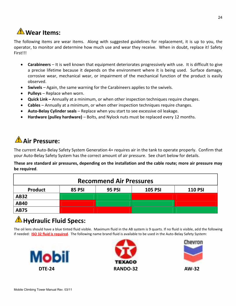
Wear Items: The following items are wear items. Along with suggested guidelines for replacement, it is up to you, the operator, to monitor and determine how much use and wear they receive. When in doubt, replace it! Safety First!!!
Carabineers – It is well known that equipment deteriorates progressively with use. It is difficult to give a precise lifetime because it depends on the environment where it is being used. Surface damage, corrosive wear, mechanical wear, or impairment of the mechanical function of the product is easily observed.
Swivels – Again, the same warning for the Carabineers applies to the swivels.
Pulleys – Replace when worn.
Quick Link – Annually at a minimum, or when other inspection techniques require changes.
Cables – Annually at a minimum, or when other inspection techniques require changes.
Auto-Belay Cylinder seals – Replace when you start to see excessive oil leakage.
Hardware (pulley hardware) – Bolts, and Nylock nuts must be replaced every 12 months.
Air Pressure:
The current Auto-Belay Safety System Generation 4+ requires air in the tank to operate properly. Confirm that your Auto-Belay Safety System has the correct amount of air pressure. See chart below for details.
These are standard air pressures, depending on the installation and the cable route; more air pressure may be required.
Recommend Air Pressures Product 85 PSI 95 PSI 105 PSI 110 PSI
AB32
AB40
AB75
Hydraulic Fluid Specs:
The oil lens should have a blue tinted fluid visible. Maximum fluid in the AB system is 9 quarts. If no fluid is visible, add the following if needed: ISO 32 fluid is required. The following name brand fluid is available to be used in the Auto-Belay Safety System:
DTE-24 RANDO-32 AW-32

25
Mobile Climbing Tower Manual Rev. 03/11
CABLE INSPECTION
26
Mobile Climbing Tower Manual Rev. 03/11
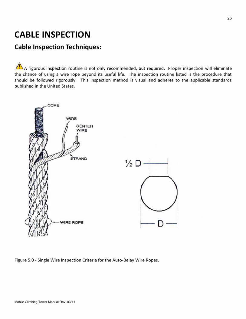
CABLE INSPECTION Cable Inspection Techniques:
A rigorous inspection routine is not only recommended, but required. Proper inspection will eliminate the chance of using a wire rope beyond its useful life. The inspection routine listed is the procedure that should be followed rigorously. This inspection method is visual and adheres to the applicable standards published in the United States.
Figure 5.0 - Single Wire Inspection Criteria for the Auto-Belay Wire Ropes.
27
Mobile Climbing Tower Manual Rev. 03/11
Replace the cable if any of the following conditions are true:
(Refer to Figure5.0)
1. If any of the individual wires in a strand have a flat spot of more that ½ the diameter of the smallest
wire as shown in Figure 5.0.
2. If there is a single broken wire in any strand.
3. If there are 50,000 or more cycles on the route.
4. If the cables have been on a climbing tower for 1 year (12 months).
5. If there are any twists, kinks, flat spots, or bird-caging.
Wire Rope Inspection Criteria recommended by various agencies and Manufacturers, Governing agencies in the United States have published guidelines pertaining to wire rope use, maintenance, inspection, and general specifications. Further, most wire rope manufacturers have additional guidelines for the use, maintenance and inspection of their cables. These guidelines and codes set precedence for the industry standard methods of use, maintenance and inspection of wire ropes. Deviation from these recommendations would be viewed as questionable by most engineers with experience in the industry. To justify the inspection method recommended by Spectrum Sports Intl, the most noted codes and guidelines have been obtained and read by SAE Inc. engineers. The codes obtained by SAE Inc. engineers include:
a. ASME (American Society of Mechanical Engineers) International Publication ASME/B30.5c – Mobile and Locomotive Cranes, 1998, ISBN#: 0791822753
This code is a revision of the ASME/ANSI B30.5-1989. It applies specifically to applications similar to the Space ShotTM ride.
b. Wire Rope Technical Board Wire Rope Users Manual, Third Edition, 1993
This test gives a summary compilation of the recommended practices for wire rope use in general applications.
c. OSHA Wire Rope Excerpts – General Standards, Vol. 37, Number 202, Oct. 1972. This general standard is a compilation of the ASME/ANSI standards that exist now as the SME/B30.XX series. These are the forerunner to current standards.
d. Leeschen Wire Rope Company “Wire rope Inspection”, Report #107. This report gives guidelines to the inspection methods appropriate to identify wire rope damage.
Each of these codes specifies, in general, the same criteria for inspection of wire ropes. Additional ASME codes specify inspection criteria for additional applications including, but not limited to personnel hoist (elevators), overhead cranes, material hoist, etc. The ASME code governing Mobile and Locomotive Cranes is very stringent. It is the most stringent code that has any applicability to the Auto-Belay. The highlights of the inspection guidelines/codes listed above are included in the next table of this document to set a comparison reference for SPECTRUM SPORTS INTL guidelines. Note that the inspection procedures outlined in the referenced codes are all visual inspections.
28
Mobile Climbing Tower Manual Rev. 03/11
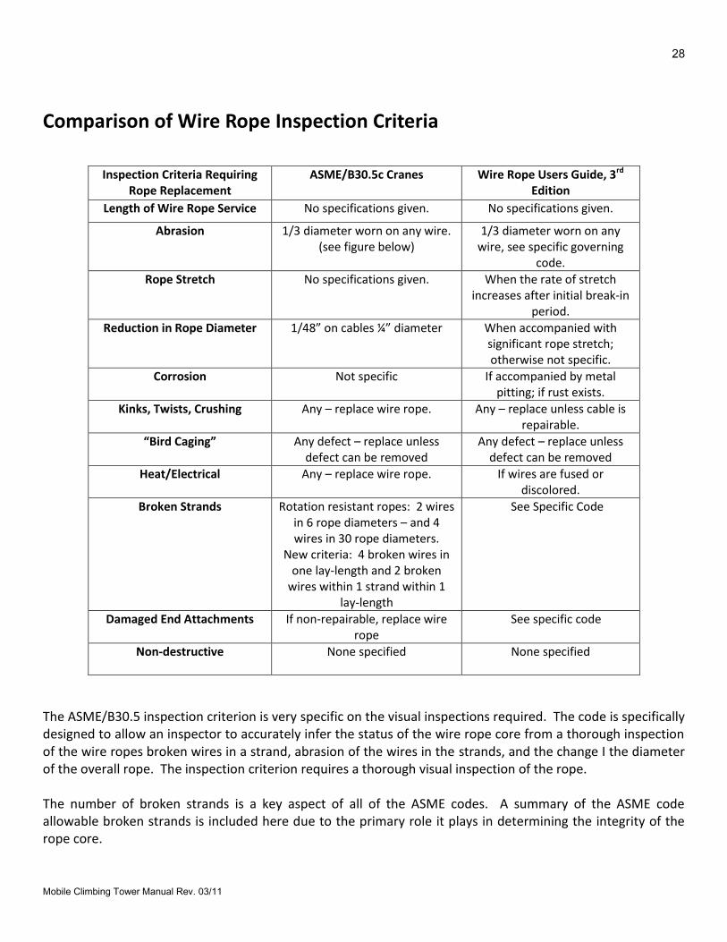
Comparison of Wire Rope Inspection Criteria
Inspection Criteria Requiring Rope Replacement
ASME/B30.5c Cranes Wire Rope Users Guide, 3rd Edition
Length of Wire Rope Service No specifications given. No specifications given.
Abrasion 1/3 diameter worn on any wire. (see figure below)
1/3 diameter worn on any wire, see specific governing
code.
Rope Stretch No specifications given. When the rate of stretch increases after initial break-in
period.
Reduction in Rope Diameter 1/48” on cables ¼” diameter When accompanied with significant rope stretch; otherwise not specific.
Corrosion Not specific If accompanied by metal pitting; if rust exists.
Kinks, Twists, Crushing Any – replace wire rope. Any – replace unless cable is repairable.
“Bird Caging” Any defect – replace unless defect can be removed
Any defect – replace unless defect can be removed
Heat/Electrical Any – replace wire rope. If wires are fused or discolored.
Broken Strands Rotation resistant ropes: 2 wires in 6 rope diameters – and 4 wires in 30 rope diameters.
New criteria: 4 broken wires in one lay-length and 2 broken
wires within 1 strand within 1 lay-length
See Specific Code
Damaged End Attachments If non-repairable, replace wire rope
See specific code
Non-destructive None specified None specified
The ASME/B30.5 inspection criterion is very specific on the visual inspections required. The code is specifically designed to allow an inspector to accurately infer the status of the wire rope core from a thorough inspection of the wire ropes broken wires in a strand, abrasion of the wires in the strands, and the change I the diameter of the overall rope. The inspection criterion requires a thorough visual inspection of the rope. The number of broken strands is a key aspect of all of the ASME codes. A summary of the ASME code allowable broken strands is included here due to the primary role it plays in determining the integrity of the rope core.
29
Mobile Climbing Tower Manual Rev. 03/11
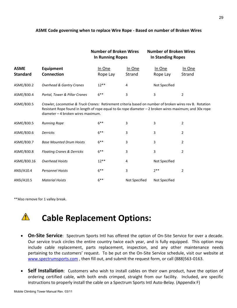
ASME Code governing when to replace Wire Rope - Based on number of Broken Wires
Number of Broken Wires Number of Broken Wires In Running Ropes In Standing Ropes ASME Equipment In One In One In One In One Standard Connection Rope Lay Strand Rope Lay Strand ASME/B30.2 Overhead & Gantry Cranes 12** 4 Not Specified ASME/B30.4 Portal, Tower & Pillar Cranes 6** 3 3 2 ASME/B30.5 Crawler, Locomotive & Truck Cranes: Retirement criteria based on number of broken wires rev B. Rotation
Resistant Rope found in length of rope equal to 6x rope diameter – 2 broken wires maximum; and 30x rope diameter – 4 broken wires maximum.
ASME/B30.5 Running Rope 6** 3 3 2 ASME/B30.6 Derricks 6** 3 3 2 ASME/B30.7 Base Mounted Drum Hoists 6** 3 3 2 ASME/B30.8 Floating Cranes & Derricks 6** 3 3 2 ASME/B30.16 Overhead Hoists 12** 4 Not Specified ANSI/A10.4 Personnel Hoists 6** 3 2** 2 ANSI/A10.5 Material Hoists 6** Not Specified Not Specified **Also remove for 1 valley break.
Cable Replacement Options:
On-Site Service: Spectrum Sports Intl has offered the option of On-Site Service for over a decade.
Our service truck circles the entire country twice each year, and is fully equipped. This option may include cable replacement, parts replacement, inspection, and any other maintenance needs pertaining to the customers’ request. To be put on the On-Site Service schedule, visit our website at www.spectrumsports.com , then fill out, and submit the request form, or call (888)563-0163.
Self Installation: Customers who wish to install cables on their own product, have the option of
ordering certified cable, with both ends crimped, straight from our facility. Included, are specific instructions to properly install the cable on a Spectrum Sports Intl Auto-Belay. (Appendix F)

30
Mobile Climbing Tower Manual Rev. 03/11
OPERATING/USING THE AUTO-BELAY
31
Mobile Climbing Tower Manual Rev. 03/11
OPERATING/USING THE AUTO-BELAY
Once you understand how the Auto-Belay works, and how to inspect it you need to understand how to operate it. Follow the steps below to ensure safe usage of the Auto-Belay system.
ATTENTION! Make sure you read and understand this section thoroughly
prior to use!
Step 1. Complete the daily checklist. Confirm that the cable has tension on it.
2. Before someone climbs, instruct the climber regarding the proper protocol to follow during and
after climbing. This includes the following: When a climber has finished climbing (reaches the top, falls, or cannot support themselves while climbing), inform them to grab hold of the red hose on the cable and “sit” in the harness with their feet toward the climbing structure. This will allow the Auto-Belay to slowly descend the climber. Inform the climber to land on their feet. Feet First!!!
3. Confirm the climbing harness is on properly and secure.
4. Unhook the Auto-Belay cable from the static/locked position and hook it to the climbing
harness. Be sure that you hear the carabineer click into locked position! Double check the tension on the cable (pulling down and feeling the up-pull).
5. Instruct the climber on how to climb, meanwhile; paying attention to the tension on the cable.
If slack occurs at anytime during the climb, STOP CLIMBING UP and slowly climb down. DO NOT LET GO and fall with slack in the cable. Serious injury may occur.
6. Once the climber has descended and is standing on the ground, unhook them from the Auto-Belay Safety System. Once they are “OFF” the Auto- Belay safety system, remove the climbing safety harness from them. Do NOT ALLOW THEM TO CLIMB ON THE TOWER WITHOUT A HARNESS AND SECURED INTO THE AUTO-BELAY Safety System.
7. Remove the person from the “Climbing Zone”.

32
Mobile Climbing Tower Manual Rev. 03/11
CLIMBING OPERATIONS
33
Mobile Climbing Tower Manual Rev. 03/11
CLIMBING OPERATIONS Required Personnel for Operations For efficient set up and operations, SSI recommends that at least two people operate for optimal performance and safety. Spectrum Sports Intl recommends that one-person acts as the climbing coach (Climb Master), supervising any one or all of the climbers that are on the climbing tower and a second person to harness the climber, contain the “CLIMBING ZONE” and (if required by the event or your insurance) obtain a parental consent or hold harmless signature. The Climb Master should offer encouragement, entertain the climber and most importantly watch the belay cable to ensure that there is no excess slack in the cable or that the climber does not out climb the Auto-Belay device. The second person in charge of harnessing should ensure the harness is worn correctly. You need to decide how many personnel are needed to ensure that safe operations are taking place. When in doubt, add other trained personnel to the attraction. By way of recommendation, as the climber climbs the unit, the Climb Master should be interactive by offering positive words of encouragement and possible hand or foothold selection. As a climber decsents after having climbed to the top, make sure the area on the ground is free of any individual who could possibly get in the way of the repelling climber. The distance we recommend is approx. six (6) feet from the front surface of the climbing product. The only person who should be in this six-foot area is the Climb Master. Upon the completion of a climb, the climber must wait for direction from the climbing coach before proceeding to the harness area for removal of the climbing harness. Likewise, the upcoming climber must be advised by either the Climb Master or the Assistant ensuring proper fitting of the harness before proceeding to climb on the wall. This will ensure that a rappelling climber will not descend onto an upcoming climber.
As an additional note, although Climbing Helmets are not required, we strongly recommend their use.
“Climb Master” The roles for the Climb Master are as follows:
Ensure each climbing zone is safe to climb (test the Auto-Belay Safety System before each climb; see Auto-Belay Safety System section in this manual).
Ensure that each climber is secured into his/her climbing harness properly.
Ensure that the Climber understands the rules of climbing on the Climbing Tower.
Ensure that the Climber understands what the climber is to expect once they decide to come down off the tower.
Ensures that the climbing route is free from any other climbers.
Ensures that the climber is able to climb (See Warning & Safety, Rules signs are followed)(see page 29).
Ensures that the Auto-Belay Safety System is retracting the cable.
Act as a coach, with encouragement and guidance.
Be positive and happy while working with the climbing tower.
Keeps the flow moving smoothly and safely in the Climbing Zone.
All of the “Assistant’s” responsibilities if he/she is working the climbing tower alone.
Knows and understands how to set up the mobile climbing tower.
Knows and understands how to take down the mobile climbing tower.
Knows and understands how to safely transport the mobile climbing tower.
34
Mobile Climbing Tower Manual Rev. 03/11
“Assistant”
The roles for the Assistant are as follows:
Ensure the climbers understands the Rules and Warnings of the Climbing Towers
Explains what is to be expected during the climbing experience on the Climbing Towers
Place the Climbers in the climbing harness
Explains to the climber the Rules and Warnings (Verbally)
Collects any tokens/tickets or money for the climbing tower
Keep the climbers out of the Climbing Zone until the Climb Master calls for them
Keep the Climbing Zone free and clear of any “NON” climbers
Keeps the “QUE” line in order
Knows and understands how to set up the mobile climbing tower
Knows and understands how to take down the mobile climbing tower
Knows and understands how to safely transport the mobile climbing tower
Ultimately it is your responsibility to ensure that each person that climbs on the Climbing Tower is safe! Practice safety first. Know the product and how it works.
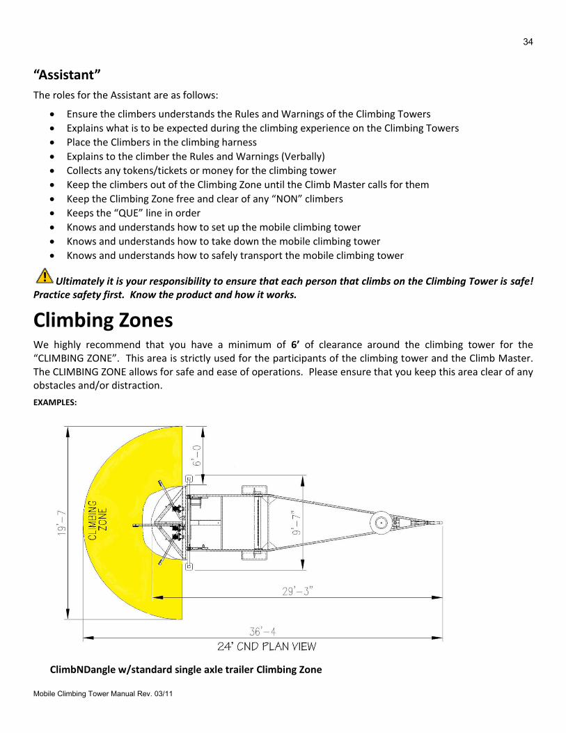
Climbing Zones We highly recommend that you have a minimum of 6’ of clearance around the climbing tower for the “CLIMBING ZONE”. This area is strictly used for the participants of the climbing tower and the Climb Master. The CLIMBING ZONE allows for safe and ease of operations. Please ensure that you keep this area clear of any obstacles and/or distraction.
EXAMPLES:
ClimbNDangle w/standard single axle trailer Climbing Zone
35
Mobile Climbing Tower Manual Rev. 03/11
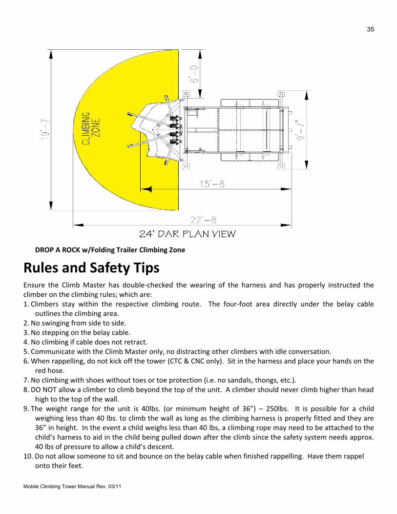
DROP A ROCK w/Folding Trailer Climbing Zone
Rules and Safety Tips Ensure the Climb Master has double-checked the wearing of the harness and has properly instructed the climber on the climbing rules; which are: 1. Climbers stay within the respective climbing route. The four-foot area directly under the belay cable
outlines the climbing area. 2. No swinging from side to side. 3. No stepping on the belay cable. 4. No climbing if cable does not retract. 5. Communicate with the Climb Master only, no distracting other climbers with idle conversation. 6. When rappelling, do not kick off the tower (CTC & CNC only). Sit in the harness and place your hands on the
red hose. 7. No climbing with shoes without toes or toe protection (i.e. no sandals, thongs, etc.). 8. DO NOT allow a climber to climb beyond the top of the unit. A climber should never climb higher than head
high to the top of the wall. 9. The weight range for the unit is 40lbs. (or minimum height of 36”) – 250lbs. It is possible for a child
weighing less than 40 lbs. to climb the wall as long as the climbing harness is properly fitted and they are 36” in height. In the event a child weighs less than 40 lbs, a climbing rope may need to be attached to the child’s harness to aid in the child being pulled down after the climb since the safety system needs approx. 40 lbs of pressure to allow a child’s descent.
10. Do not allow someone to sit and bounce on the belay cable when finished rappelling. Have them rappel onto their feet.
36
Mobile Climbing Tower Manual Rev. 03/11
Emergency Climber Recovery It may be necessary for the Climb Master to climb the product to retrieve a person who may be frozen in place, afraid to come down after they have climbed to a specific height. If this is the case, the emergency guideline is for the Climb Master to have the assistant place him/her in a climbing harness, once the climbing harness is secure, the assistant will connect the Auto-Belay safety system to the Climb Master on the route next to the person in trouble and climb up the person, if the Climb Master cannot talk the person down, the Climb Master must grab the Auto-Belay cable that is attached to the person in trouble and pull and drop to the ground at the same time, the weight of the Climb Master will pull the person off the wall and the Auto-Belay Safety System (s) will lower them both to the ground safely.
NEVER REMOVE THE AUTO-BELAY Safety System Cable/Carabineer from any climber/participant while they are climbing on the climbing tower.

37
Mobile Climbing Tower Manual Rev. 03/11
MOBILE CLIMBING TOWER INSPECTIONS
38
Mobile Climbing Tower Manual Rev. 03/11
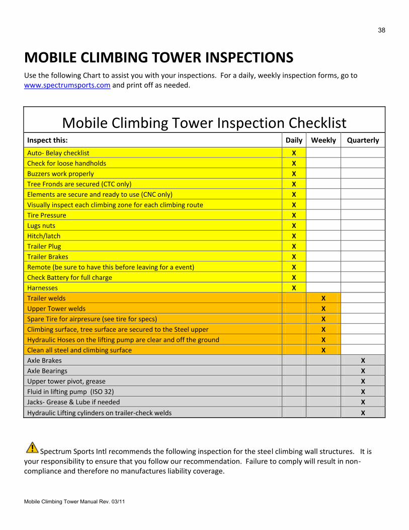
MOBILE CLIMBING TOWER INSPECTIONS Use the following Chart to assist you with your inspections. For a daily, weekly inspection forms, go to www.spectrumsports.com and print off as needed.
Mobile Climbing Tower Inspection Checklist Inspect this: Daily Weekly Quarterly
Auto- Belay checklist X
Check for loose handholds X
Buzzers work properly X
Tree Fronds are secured (CTC only) X
Elements are secure and ready to use (CNC only) X
Visually inspect each climbing zone for each climbing route X
Tire Pressure X
Lugs nuts X
Hitch/latch X
Trailer Plug X
Trailer Brakes X
Remote (be sure to have this before leaving for a event) X
Check Battery for full charge X
Harnesses X
Trailer welds X
Upper Tower welds X
Spare Tire for airpresure (see tire for specs) X
Climbing surface, tree surface are secured to the Steel upper X
Hydraulic Hoses on the lifting pump are clear and off the ground X
Clean all steel and climbing surface X
Axle Brakes X
Axle Bearings X
Upper tower pivot, grease X
Fluid in lifting pump (ISO 32) X
Jacks- Grease & Lube if needed X
Hydraulic Lifting cylinders on trailer-check welds X
Spectrum Sports Intl recommends the following inspection for the steel climbing wall structures. It is your responsibility to ensure that you follow our recommendation. Failure to comply will result in non-compliance and therefore no manufactures liability coverage.
39
Mobile Climbing Tower Manual Rev. 03/11
NON DESTRUCTIVE EXAMINATION (NDE)
Inspection Policy Spectrum Sports Intl has third party structural analysis for all of our products since 2004, these analysis call out for “visual Inspections” for specific items. Spectrum Sports Intl requires visual inspections of applicable items as called out in the “Inspections” section of the product owners/operators manual. The daily, weekly and quarterly must be completed to ensure safe operations of all products.

40
Mobile Climbing Tower Manual Rev. 03/11
TRANSPORTATION
CHECKLIST
41
Mobile Climbing Tower Manual Rev. 03/11
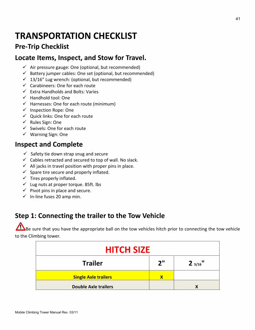
TRANSPORTATION CHECKLIST Pre-Trip Checklist
Locate Items, Inspect, and Stow for Travel. Air pressure gauge: One (optional, but recommended) Battery jumper cables: One set (optional, but recommended) 13/16” Lug wrench: (optional, but recommended) Carabineers: One for each route Extra Handholds and Bolts: Varies Handhold tool: One Harnesses: One for each route (minimum) Inspection Rope: One Quick links: One for each route Rules Sign: One Swivels: One for each route Warning Sign: One
Inspect and Complete Safety tie down strap snug and secure Cables retracted and secured to top of wall. No slack. All jacks in travel position with proper pins in place. Spare tire secure and properly inflated. Tires properly inflated. Lug nuts at proper torque. 85ft. lbs Pivot pins in place and secure. In-line fuses 20 amp min.
Step 1: Connecting the trailer to the Tow Vehicle
Be sure that you have the appropriate ball on the tow vehicles hitch prior to connecting the tow vehicle
to the Climbing tower.
HITCH SIZE
Trailer 2" 2 5/16"
Single Axle trailers X
Double Axle trailers X
42
Mobile Climbing Tower Manual Rev. 03/11
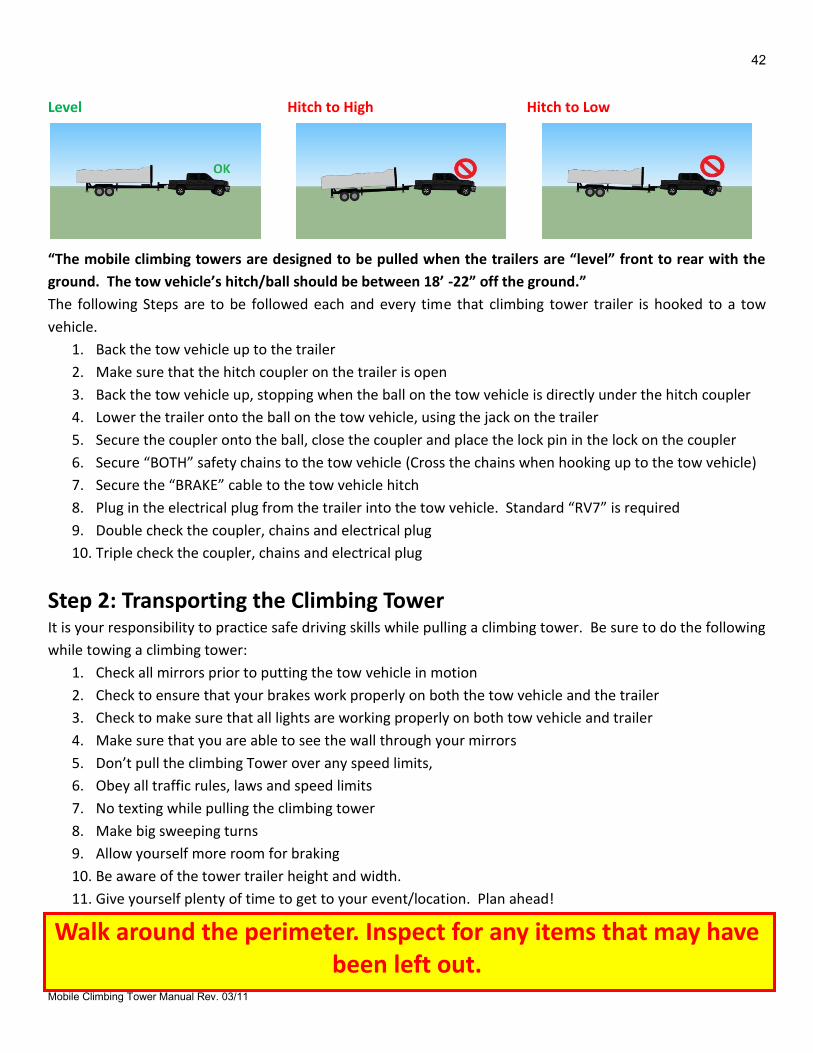
Level Hitch to High Hitch to Low
“The mobile climbing towers are designed to be pulled when the trailers are “level” front to rear with the
ground. The tow vehicle’s hitch/ball should be between 18’ -22” off the ground.”
The following Steps are to be followed each and every time that climbing tower trailer is hooked to a tow
vehicle.
1. Back the tow vehicle up to the trailer
2. Make sure that the hitch coupler on the trailer is open
3. Back the tow vehicle up, stopping when the ball on the tow vehicle is directly under the hitch coupler
4. Lower the trailer onto the ball on the tow vehicle, using the jack on the trailer
5. Secure the coupler onto the ball, close the coupler and place the lock pin in the lock on the coupler
6. Secure “BOTH” safety chains to the tow vehicle (Cross the chains when hooking up to the tow vehicle)
7. Secure the “BRAKE” cable to the tow vehicle hitch
8. Plug in the electrical plug from the trailer into the tow vehicle. Standard “RV7” is required
9. Double check the coupler, chains and electrical plug
10. Triple check the coupler, chains and electrical plug
Step 2: Transporting the Climbing Tower It is your responsibility to practice safe driving skills while pulling a climbing tower. Be sure to do the following
while towing a climbing tower:
1. Check all mirrors prior to putting the tow vehicle in motion
2. Check to ensure that your brakes work properly on both the tow vehicle and the trailer
3. Check to make sure that all lights are working properly on both tow vehicle and trailer
4. Make sure that you are able to see the wall through your mirrors
5. Don’t pull the climbing Tower over any speed limits,
6. Obey all traffic rules, laws and speed limits
7. No texting while pulling the climbing tower
8. Make big sweeping turns
9. Allow yourself more room for braking
10. Be aware of the tower trailer height and width.
11. Give yourself plenty of time to get to your event/location. Plan ahead!
Walk around the perimeter. Inspect for any items that may have been left out.
43
Mobile Climbing Tower Manual Rev. 03/11
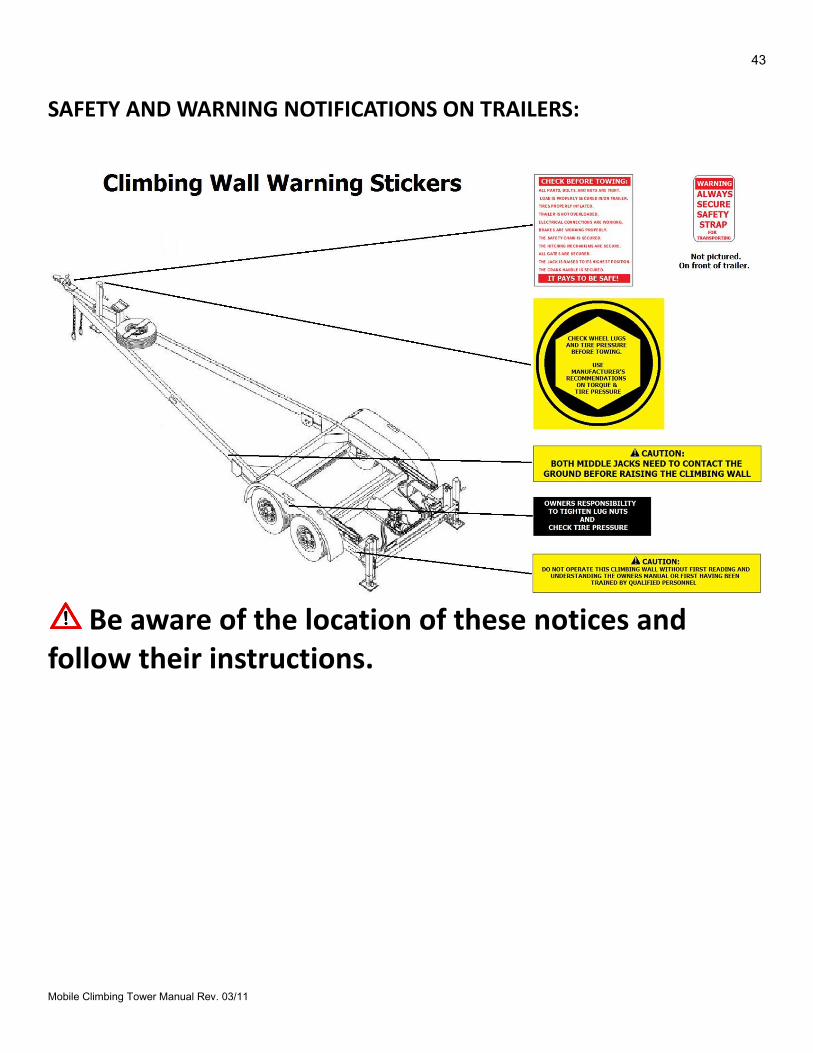
SAFETY AND WARNING NOTIFICATIONS ON TRAILERS:
Be aware of the location of these notices and follow their instructions.

44
Mobile Climbing Tower Manual Rev. 03/11
PRODUCT “SET-UP”
INSTRUCTIONS
45
Mobile Climbing Tower Manual Rev. 03/11
PRODUCT “SET-UP” INSTRUCTIONS Required Personnel for “set up” and “take down” Most of our mobile climbing towers can be set up and taken down with only one person. However, for efficient and safe operations, SSI recommends that at least two people for optimal performance and safety. Spectrum Sports Intl recommends that one-person act as the climbing coach (Climb Master), this person being very knowledgeable and experienced with the climbing tower and the product set up and take down procedures, experienced in towing a trailer and backing up a trailer. The Climb Master should understand and know this manual very well. Understanding the importance of following each step and guideline within this manual. The Climb Master is also responsible for; supervising any one or all of the climbers that are on the climbing tower and in the “CLIMBING ZONE” and (if required by the event or your insurance) obtain a parental consent or hold harmless signature. The Climb Master should offer encouragement, entertain the climber and most importantly watch the belay cable to ensure that there is no excess slack in the cable or that the climber does not out climb the Auto-Belay device. The second person, needs to assist the Climb Master with the set up and take down of the climbing tower, they also need to understand how to safely operate the climbing tower. Also they are in charge of harnessing, ensuring the harness is worn correctly. You need to decide how many personnel are needed to ensure that safe operations are taking place. When in doubt, add other trained personnel to the attraction.
Step 1: Locate Your Safe Climbing Tower “Set Up” Area Place the climbing tower in a safe area to operate. This may require that you move the climbing tower many times in order to find the correct spot. It is recommended that you plan ahead and visit the location and make notes on where you are to set up the climbing tower. The following guidelines are to be followed while looking for a location:
1. Level ground (VERY IMPORTANT, do not raise the tower unless the ground is level). 2. Firm ground. 3. Plenty of room to get the climbing tower in place. 4. Plenty of room for the “Climbing Zone”. 5. The area is clear from any overhead power lines, trees or building overhangs.
Step 2: Observe Any Overhead Obstacles
BE AWARE OF ANY OVERHEAD DANGERS. Never set up a climbing tower in an area that has overhead power lines or utility lines. Find a new location or
DO NOT set up the climbing tower.
Death or serious injury may result.
46
Mobile Climbing Tower Manual Rev. 03/11
Step 3: Park Climbing Tower in Safe Area
Once you have found the perfect place to erect the climbing tower. Turn the tow vehicle off and set the
emergency brake.
Walk around the climbing tower again to ensure that the:
Ground is level.
No overhead obstacles.
You have room for your “Climbing Zone”.
Step 4: Unhook Trailer from Tow Vehicle
All Spectrum Sports Intl products are engineered to be operated without being connected to the towing
vehicle. Leaving the trailers attached to the tow vehicles may cause damage to the trailer hitch and cause it to
break and may cause an accident and maybe death!!!!!
“ALL TRAILERS MUST BE UNHOOKED FROM THE TOW VEHICLE PRIOR TO PROCEEDING TO THE NEXT STEP”
The following steps are to be followed:
1. Unplug the electrical plug from the tow vehicle
2. Remove the safety chains
3. Remove the safety brake wire
4. Go to the back of the trailer and drop the lower section on each jack on each side of the trailer.
5. Pull the rear jacks out to the appropriate distance and place the pin into the hole through the trailer
frame
6. Add enough pressure to the rear jacks to start to raise the trailer
7. Drop the lower jack leg on the front jack on the trailer
8. Remove the pin on the trailer coupler and open the coupler’s safety latch/guard
9. Using the front jack, raise the front of the trailer up 2”
10. Go back to the front of the trailer and finish raising the front of the trailer until the ball/hitch on the
tow vehicle is 1” below the coupler on the trailer
Step 5: Level Trailer The trailer needs to be level during set up and operation of the climbing tower. Be sure to use the front and rear jacks on the trailer to level the trailer front to back and side to side. The trailer tires should be 3 -5” off the ground to ensure proper tower set up. If you do not have the trailer tires off the ground, the tower frame will drag along the ground and possibly bend all the jacks and damage the tower steel and the trailer. Once the trailer is leveled, use the stabilizing jacks to secure the trailer. The stabilizing Jacks are very important and part of the overall safety of the mobile tower.
47
Mobile Climbing Tower Manual Rev. 03/11
Failure to use the stabilizing jacks may result in a broken trailer frame and or other welds on the climbing structure
Step 6: Remove Travel Safety Strap The “Travel Safety Strap” must be removed prior to raising the Climbing Tower. Be sure to unhook the strap and place it in the tow vehicle for the “Take Down” procedures
Step 7: Prep Climbing Tower
This is the time to prep the tower for any miscellaneous items like:
Banners
Timers
Flags
Tree Fronds
Bells
Install all miscellaneous items securely, it is your responsibility to ensure that they will not fall off and injure any persons around the climbing tower.
Also check for loose handholds. Pull the “Auto-Belay” cables to the bottom of the tower and secure in the “EYE BOLT”
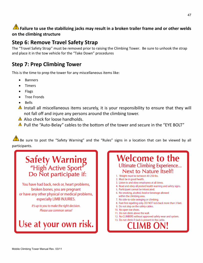
Be sure to post the “Safety Warning” and the “Rules” signs in a location that can be viewed by all
participants.
48
Mobile Climbing Tower Manual Rev. 03/11
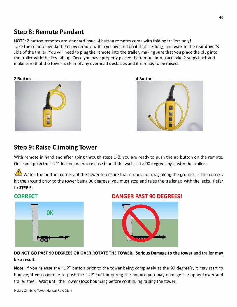
Step 8: Remote Pendant NOTE: 2 button remotes are standard issue, 4 button remotes come with folding trailers only! Take the remote pendant (Yellow remote with a yellow cord on it that is 3’long) and walk to the rear driver’s side of the trailer. You will need to plug the remote into the trailer, making sure that you place the plug into the trailer with the key tab up. Once you have properly placed the remote into place take 2 steps back and make sure that the tower is clear of any overhead obstacles and it is ready to be raised.
2 Button 4 Button
Step 9: Raise Climbing Tower
With remote in hand and after going through steps 1-8, you are ready to push the up button on the remote.
Once you push the “UP” button, do not release it until the wall is at a 90 degree angle with the trailer.
Watch the bottom corners of the tower to ensure that it does not drag along the ground. If the corners
hit the ground prior to the tower being 90 degrees, you must stop and raise the trailer up with the jacks. Refer
to STEP 5.
CORRECT DANGER PAST 90 DEGREES!
DO NOT GO PAST 90 DEGREES OR OVER ROTATE THE TOWER. Serious Damage to the tower and trailer may
be a result.
Note: if you release the “UP” button prior to the tower being completely at the 90 degree’s, it may start to
bounce; if you continue to push the “UP” button during the bounce you may damage the upper tower and
trailer steel. Wait until the Tower stops bouncing before continuing raising the tower.
49
Mobile Climbing Tower Manual Rev. 03/11
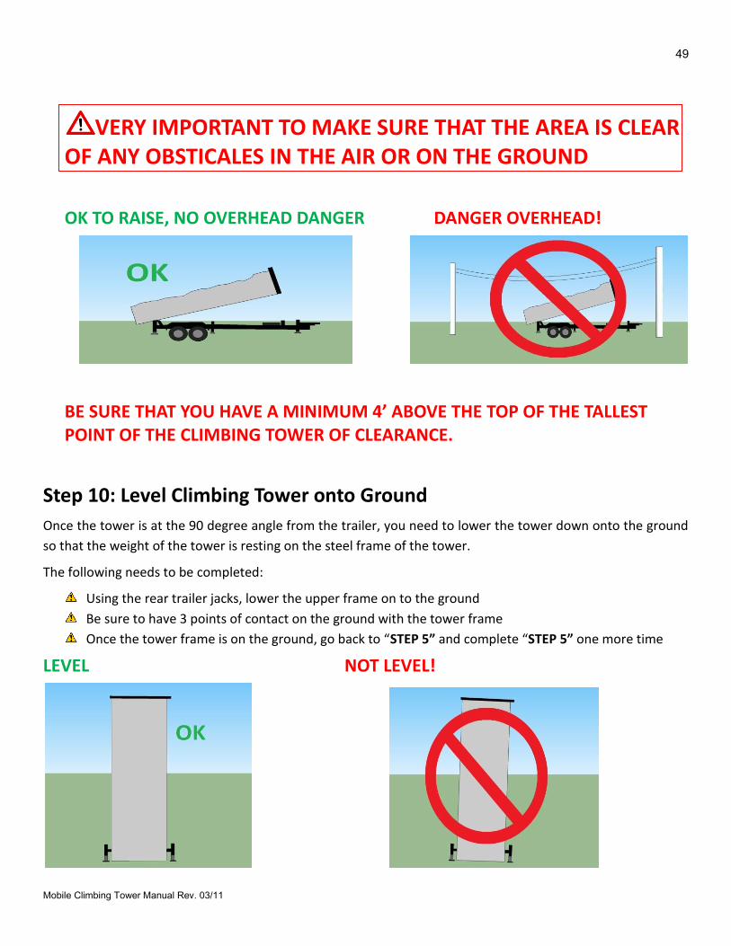
VERY IMPORTANT TO MAKE SURE THAT THE AREA IS CLEAR OF ANY OBSTICALES IN THE AIR OR ON THE GROUND
OK TO RAISE, NO OVERHEAD DANGER DANGER OVERHEAD!
BE SURE THAT YOU HAVE A MINIMUM 4’ ABOVE THE TOP OF THE TALLEST POINT OF THE CLIMBING TOWER OF CLEARANCE.
Step 10: Level Climbing Tower onto Ground
Once the tower is at the 90 degree angle from the trailer, you need to lower the tower down onto the ground
so that the weight of the tower is resting on the steel frame of the tower.
The following needs to be completed:
Using the rear trailer jacks, lower the upper frame on to the ground
Be sure to have 3 points of contact on the ground with the tower frame
Once the tower frame is on the ground, go back to “STEP 5” and complete “STEP 5” one more time
LEVEL NOT LEVEL!
50
Mobile Climbing Tower Manual Rev. 03/11
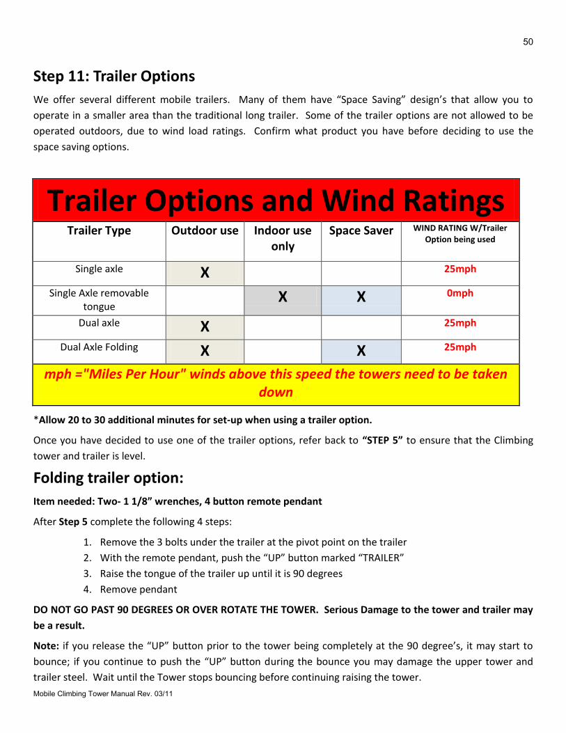
Step 11: Trailer Options
We offer several different mobile trailers. Many of them have “Space Saving” design’s that allow you to
operate in a smaller area than the traditional long trailer. Some of the trailer options are not allowed to be
operated outdoors, due to wind load ratings. Confirm what product you have before deciding to use the
space saving options.
Trailer Options and Wind Ratings Trailer Type Outdoor use Indoor use
only Space Saver WIND RATING W/Trailer
Option being used
Single axle X 25mph
Single Axle removable tongue
X X 0mph
Dual axle X 25mph
Dual Axle Folding X X 25mph
mph ="Miles Per Hour" winds above this speed the towers need to be taken down
*Allow 20 to 30 additional minutes for set-up when using a trailer option.
Once you have decided to use one of the trailer options, refer back to “STEP 5” to ensure that the Climbing
tower and trailer is level.
Folding trailer option: Item needed: Two- 1 1/8” wrenches, 4 button remote pendant
After Step 5 complete the following 4 steps:
1. Remove the 3 bolts under the trailer at the pivot point on the trailer
2. With the remote pendant, push the “UP” button marked “TRAILER”
3. Raise the tongue of the trailer up until it is 90 degrees
4. Remove pendant
DO NOT GO PAST 90 DEGREES OR OVER ROTATE THE TOWER. Serious Damage to the tower and trailer may
be a result.
Note: if you release the “UP” button prior to the tower being completely at the 90 degree’s, it may start to
bounce; if you continue to push the “UP” button during the bounce you may damage the upper tower and
trailer steel. Wait until the Tower stops bouncing before continuing raising the tower.
51
Mobile Climbing Tower Manual Rev. 03/11
Removable Tongue option:
Item needed:
After Step 5 complete the following 4 steps:
1. Unplug the electrical plugs in front of the trailer fender on the driver’s side
2. Unclip the pin and remove the pin (red handled PIN)
3. Pull the tongue straight out and store in a safe place.
Step 12: Auto-Belay Prep
Priming of the Auto-Belay: (this is to be completed when the climbing tower is vertical)
Before each use of the Auto-Belay you must do the following: With one operator on the front of the wall using a rope, manually extend the cable to the top of the wall while a second person inspects the retraction of the cable to ensure there is NO SLACK behind the wall. Ensure that all pulleys turn when the cable is in motion and that cable drag is minimal.
The following steps need to be done before the Auto-Belay safety system is used (each time)
Check the air pressure to confirm that it is within the safe operating range (Consult the sticker on the side of your Auto-Belay system).
Check the cable to ensure that it can travel thru the pulley’s with-out restriction.
Check the oil-site for fluid.
Pull on the cable (front side of the wall) and make sure that the cable retracts itself, do this several times, all along making sure that the cable has an elastic feel.
While standing on the front side of the wall (the side that you climb on), hold on to the cable and raise it above your head and pull it to the ground (Priming the Auto-Belay safety system). Do this multiple times.
Once you have primed the system, hook into the Auto-Belay safety system and climb up 5’, then let go, allowing the Auto-Belay safety system to lower you to the ground.
Continue to climb up the wall 5’ at a time and allowing the system to lower you down, repeat until you have reached the top.
Once you have ensured that the Auto-Belay safety system is operating properly you can now allow clients to climb.
Remember, fluid levels should be checked when all Auto-Belay routes are anchored to the bottom of the wall (meaning that the carabineer-end of the cable must be in the “start climbing” position). In the vertical position if any questions, please call SPECTRUM SPORTS INTL.
For proper and safe Auto-Belay function, it is important that the Auto-Belay is properly pressurized.

52
Mobile Climbing Tower Manual Rev. 03/11
PRODUCT “TAKE-DOWN” INSTRUCTIONS
53
Mobile Climbing Tower Manual Rev. 03/11
PRODUCT “TAKE-DOWN” INSTRUCTIONS Step 1: Auto-Belay Prep
You need to release the Auto-Belay safety cables to the top of the climbing wall prior to lowering the tower on
to the trailer.
You must use the inspection rope and hook the Auto-Belay safety cable carabineer through the rope and
slowly raise it to the top of the tower/davit. Pull rope through the carabineer and repeat.
We do not recommend “Letting Go” of the Auto-Belay safety cable and allowing the rubber hose to absorb the
impact. This will wear the hose prematurely and also run the risk of getting the cable jammed in the upper
pulleys.
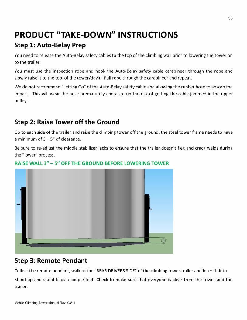
Step 2: Raise Tower off the Ground
Go to each side of the trailer and raise the climbing tower off the ground, the steel tower frame needs to have
a minimum of 3 – 5” of clearance.
Be sure to re-adjust the middle stabilizer jacks to ensure that the trailer doesn’t flex and crack welds during
the “lower” process.
RAISE WALL 3” – 5” OFF THE GROUND BEFORE LOWERING TOWER
Step 3: Remote Pendant
Collect the remote pendant, walk to the “REAR DRIVERS SIDE” of the climbing tower trailer and insert it into
Stand up and stand back a couple feet. Check to make sure that everyone is clear from the tower and the
trailer.
54
Mobile Climbing Tower Manual Rev. 03/11
Step 4: Lower Climbing Tower onto Trailer
The tower frame is 3 -5” off the ground, the remote pendant is in place and you are ready to lower the tower
onto the trailer. Stand back as far as the remote pendant will allow (around 2 ½ feet). Look around and
confirm that you are clear to lower the tower. Push the down button. Once you start to push the “down”
button, do not let go of it unless you see something that is wrong. Once the tower hits the trailer frame and
the wall is in the “DOWN/Transport” position. Hold the “DOWN” button for the count 3, one thousand 1, one
thousand 2 one thousand 3. Then let off the “DOWN” button. Remove the pendant remote and secure it
safely.
Step 5: Secure Travel Safety Strap
Connect the Travel Safety strap to the tower upper and the trailer and tighten. Be sure to secure this as tight
as possible. This will eliminate any “bouncing” of the tower on the trailer during transport.
Step 6: Remove Any Banners, Etc.
Remove all non-towable items like: banner, timers etc…
Stow them in a secure place for transport.
Step 7: Store Misc Items and Safety Climbing Gear
Stow them in a secure place for transport. Be sure to secure the following:
Auto-Belay cables to the upper A-Frame and davits at the top of the wall. (this will eliminate
premature wear and tear on both the climbing tower and the climbing hardware)
Make sure the “Remote Pendant” is in a safe and secure storage place
Warning and safety signs are placed back into the black storage bag
Harnesses are inspected and stowed in the black storage bag
Step 8: Lower Trailer to Ground
Start with the middle stabilizing jacks, remove all pressure from them and get them ready to travel, fold and
store. Then proceed to the rear of the climbing tower and lower the trailer by using the rear jacks. Once the
trailer is resting on the tires back the tow vehicle to the trailer hitch.
If you are taking down the tower by yourself, you must only lower each side a couple inches at a time, go
back and forth on both sides and lower it to the ground equally. If not you may damage the jacks!
55
Mobile Climbing Tower Manual Rev. 03/11
Step 9: Prep Trailer for Transport
Walk around the climbing tower and trailer once again and confirm that it is ready for transport.
Check the following:
Cables are up at the top of the wall and secured to the A-Frame
All equipment and climbing gear is stowed
Remote Pendant is secure
All jacks are placed back into the transport positions.
Travel Safety Strap is in place and secure
Step 10: Pre-Trip Check List
Locate Items, Inspect, and Stow for Travel. Air pressure gauge: One (optional, but recommended) Battery jumper cables: One set (optional, but recommended) 13/16” Lug wrench: (optional, but recommended) Carabineers: One for each route Extra Handholds and Bolts: Varies Handhold tool: One Harnesses: One for each route (minimum) Inspection Rope: One Quick links: One for each route Rules Sign: One Swivels: One for each route Warning Sign: One
Inspect and Complete Safety tie down strap snug and secure Cables retracted and secured to top of wall. No slack. All jacks in travel position with proper pins in place. Spare tire secure and properly inflated. Tires properly inflated. Lug nuts at proper torque. 85ft. lbs Pivot pins in place and secure. In-line fuse 20 amp min.
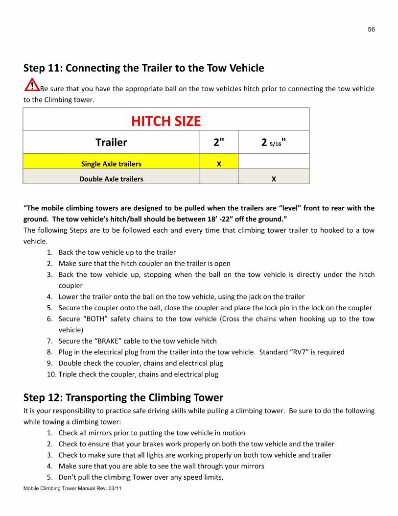
56
Mobile Climbing Tower Manual Rev. 03/11
Step 11: Connecting the Trailer to the Tow Vehicle
Be sure that you have the appropriate ball on the tow vehicles hitch prior to connecting the tow vehicle
to the Climbing tower.
HITCH SIZE
Trailer 2" 2 5/16"
Single Axle trailers X
Double Axle trailers X
“The mobile climbing towers are designed to be pulled when the trailers are “level” front to rear with the
ground. The tow vehicle’s hitch/ball should be between 18’ -22” off the ground.”
The following Steps are to be followed each and every time that climbing tower trailer to hooked to a tow
vehicle.
1. Back the tow vehicle up to the trailer
2. Make sure that the hitch coupler on the trailer is open
3. Back the tow vehicle up, stopping when the ball on the tow vehicle is directly under the hitch
coupler
4. Lower the trailer onto the ball on the tow vehicle, using the jack on the trailer
5. Secure the coupler onto the ball, close the coupler and place the lock pin in the lock on the coupler
6. Secure “BOTH” safety chains to the tow vehicle (Cross the chains when hooking up to the tow
vehicle)
7. Secure the “BRAKE” cable to the tow vehicle hitch
8. Plug in the electrical plug from the trailer into the tow vehicle. Standard “RV7” is required
9. Double check the coupler, chains and electrical plug
10. Triple check the coupler, chains and electrical plug
Step 12: Transporting the Climbing Tower It is your responsibility to practice safe driving skills while pulling a climbing tower. Be sure to do the following
while towing a climbing tower:
1. Check all mirrors prior to putting the tow vehicle in motion
2. Check to ensure that your brakes work properly on both the tow vehicle and the trailer
3. Check to make sure that all lights are working properly on both tow vehicle and trailer
4. Make sure that you are able to see the wall through your mirrors
5. Don’t pull the climbing Tower over any speed limits,
57
Mobile Climbing Tower Manual Rev. 03/11
6. Obey all traffic rules, laws and speed limits
7. No texting while pulling the climbing tower
8. Make big sweeping turns
9. Watch your side mirrors
10. Allow yourself more room for braking
11. Be aware of the tower trailer height and width.
12. Give yourself plenty of time to get to your event/location. Plan ahead!
Walk around the perimeter. Inspect for any items that may have been left out.

58
Mobile Climbing Tower Manual Rev. 03/11
MAINTENANCE
59
Mobile Climbing Tower Manual Rev. 03/11
MAINTENANCE Maintenance & Service
We recommend that you follow the manufactures guidelines for the maintenance on your climbing tower.
Under no circumstances should any unqualified person(s) service the unit. Any work to the steel frame,
fiberglass body, hydraulic Auto-Belay and cabling should be performed by an experienced person in the field
of service who is certified, bonded, etc., to perform the work. It is the owners’ responsibility to ask for such
certification and/or bonding verification.
Follow the Manufactures check list and keep records of all your maintenance. We recommend that you keep
a service log and inspection log as well as all receipts and invoices that pertain to your product.
Spectrum Sports Intl offers On-Site service for your confidence and safety. We offer the following services:
Cable change outs
Product training
Inspections
Minor product repair
Auto-Belay Safety System rebuild’s
Visit our website for more service options and to sign up for our On-Site service. www.spectrumsports.com
Spectrum Sports Intl will not warranty or stand behind any Mobile Climbing Tower and/or Auto-Belay safety system that we have manufactured that does not use genuine and/or authorized replacement parts and/or cable. Any work and/or service that’s performed on any Spectrum Sports Intl Auto-Belay safety systems that is not performed by an authorized Spectrum Sports Intl employee, voids any and all claims to any manufacturer’s liability.
Cleaning Cleaning of the unit should be similar to an automobile (i.e. car wash with spray washers and mild detergents).
We recommend that you dry the climbing tower after each time you clean it.
Wash with mild cleaners and rinse, dry product completely before use or storage. Do not allow water to “SIT”
or “DRY” on the product.
Steel frame
Auto-Belay Safety System
Climbing surface
Tree surface
Elements
Banners
60
Mobile Climbing Tower Manual Rev. 03/11
Tree Fronds
We do recommend using a furniture polish (without natural oils) to help keep all Steel clean and polished. It
Places a light layer of wax on the steel and helps protect it and refreshes the finish. This also allows you to look
at the welds and inspect the product.
For harnesses, and other items not listed above please refer to the original manufactures’
recommendations.
Handhold cleaning is best performed using a “citrus degreaser” (type of detergent) and a sprayer at a
local car wash.
Use Caution if you use a pressure washer, DO NOT put the nozzle directly at the product, and you may
damage the product.
Do not use any mineral spirits, acids or other harmful chemical products on your climbing towers.
Product Storage (Winterization) If you’re climbing tower will not be in service for a period of 30 days or more, we recommend the following procedures to keep it free from defects and in optimal operating condition.
Store cables so Auto-Belay cylinders are retracted at bottom of product).
Depressurize (release air pressure) from belay tanks.
Disconnect battery cables from battery (disconnect ground cable first). Store the battery indoors (off the ground).
Lubricate the T-nuts and handhold bolts with silicone lubrication spray from backside of climbing wall.
Cover the horn with a plastic bag.
Remove swivels and carabineers and attach cable to bolt hanger with quick link.
Place all items that are removable in a dry location (harnesses, signs, banners etc….)
Store entire product under roof or tarp
If you have any questions or concerns, please call Spectrum Sports Intl at (435)792-3883, or email us at [email protected]

61
Mobile Climbing Tower Manual Rev. 03/11
WARRANTY
62
Mobile Climbing Tower Manual Rev. 03/11
PRODUCT WARRANTY (The warranty is established from the date of invoice.)
Product Warranty: 90 Days. Wear parts are not included under this warranty. Warranty is only extended to the original owner. After 90 days per the following:
Steel Frame – Limited Life Time on upper pulley cart and Belay tank. Does not include any frame damage due to improper installation or damage due to misuse.
Powder Coating – 90 Days. Does not include any blemish due to normal wear and/or abusive use. Warranty is limited.
Hydraulic Cylinder(s) – 90 days per manufacturer specifications. Does not include normal wear and tear. Void if determined that any other Hydraulic Fluid, other than what has been specified by manufacturer, has been used. If questions, please call SPECTRUM SPORTS INTL.
Cable (SPECTRUM SPORTS INTL Certified) – 90 Days
Climbing Surface- 90 days. On climbing surfaces it is not unusual to have cracks and air pockets in the part. This is normal and repair of this is not covered under this warranty
Steel Trailer and Steel Tower Uppers- 1 year on welds and structure. Any cracks in the steel must be reported to Spectrum Sports Intl immediately, we will determine if the crack is structural or operator error is step up.
Handholds, Banners, Timers, and other misc parts- 90 Days. Wear and Tear is not included under this warranty.
General warranty conditions do NOT include shipping costs to Spectrum Sports Intl.
On items that can be shipped by US Postal and/or overnight parcel carriers, SPECTRUM SPORTS INTL will pay for the same class or rate of service on return shipment as it was received from customer. Spectrum Sports Intl uses fabricators, distributors and/or service agents local to customer for steel, fiberglass, and hydraulic parts to determine cause and/or repair of this particular part. Should it be determined that the defect is due to abuse or misuse, any and all warranty rights or responsibilities are void. Spectrum Sports Intl reserves the right to void warranty service on any modification to product done by customer. Spectrum Sports Intl is in no way responsible for lost revenue or income while product is not in operation due to warranty or any other problems due to installation and/or operations.
Spectrum Sports Intl: Limited Warranty, Limited Remedy and Liability Release
(It is important to read all of the components of this manual and form).
Limited Warranty:
Spectrum Sports Intl warranties and obligations set forth below are in lieu of any other express warranties or obligations of Spectrum Sports Intl, its distributors, or resellers/retailers. The warranties and limitations extend are only for the person who originally purchased the product.
Per the warranty section of this manual, Spectrum Sports Intl for a period of 90-days or life time, depending upon the item or stated claim (see Warranty section) from date of purchase will at manufacturer’s option, repair or replace at no charge, and Spectrum Sports Intl CLIMBING TOWERS & AUTO-BELAY SAFETY SYSTEM which breaks or is defective in materials or workmanship. Damage due to misuse, abuse or modification is excluded – as is normal wear (such as indicated in the warranty section), dings, scratches, seal wear, cable wear, pulley wear, etc.
63
Mobile Climbing Tower Manual Rev. 03/11
Any modifications to any part of the Spectrum Sports Intl product or modifications of any of the third party products that are included with the product, will forfeit any warranty claim. The product must be in the original form from the manufacture.
Cleaning and Maintenance:
Under no circumstances should the unit be serviced by any unqualified person(s). Any work to the steel frame, hydraulic Auto-Belay or cable/roping should be performed by and experienced person in the field of service who is certified, bonded, etc., to perform the work. It is the owners’ responsibility to ask for such certification and/or bonding verification.
Cleaning of the unit should be similar to an automobile (i.e. car wash with spray washers and mild detergents). Any person(s) who work on the Auto-Belay and are not authorized and/or not trained by SPECTRUM SPORTS INTL, will take 100% responsibility and liability on the product.
Limitation of Remedy:
During the period of warranty, SPECTRUM SPORTS INTL will do everything we can to answer and resolve any questions or concerns on the products we sell. SPECTRUM SPORTS INTL has the right to evaluate if a product is under warranty. To obtain repair or replacement parts, call or fax Spectrum Sports Intl customer service for a return authorization number. Include the following information: name, address, date of purchase, address where product is located, office phone or mobile phone (if at an event), and your product model and serial number. At your expense, ship or deliver the product to SPECTRUM SPORTS INTL: 3785 N. HWY 91-Hyde Park-Utah-84318. Replaced or repaired items will be shipped back to you at no cost and will be shipped in the same manner as it was received (i.e. overnight, ground, etc.). For items that must be received before the defective part is sent to SPECTRUM SPORTS INTL it is REQUIRED that a valid credit card be charged for the warranty item before SPECTRUM SPORTS INTL will ship. Once SPECTRUM SPORTS INTL receives the old part, a credit will be issued back to the credit card.
Release of Liability:
I understand and am aware that the use of climbing towers with Auto-Belays is a hazardous activity. I understand that I am solely responsible for safe operation, daily inspection and maintenance and customer adherence to the rules. I understand that rock climbing involves a risk of injury to any and all parts of my body and the customers who use this product. I HEREBY AGREE TO FREELY AND EXPRESSLY ASSUME AND ACCEPT ANY AND ALL RISKS OF INJURY OR DEATH TO THE USER OF THIS EQUIPMENT.
I will agree that I will release Spectrum Sports Intl its manufacturer, its distributors and retailers from any and all responsibility or liability for injuries or damages to the user of the climbing products I am purchasing, or to any other person. I agree not to make a claim against or sue Spectrum Sports Intl, its manufacturers, its distributors or retailers for injuries or damages relating to use of the equipment, other than such clams as are allowed by the limited warranty set forth above.
Agreement:
I understand how to operate the climbing product safely. This means that I do understand, but not necessarily limited to, how the Auto-Belay works on the climbing products, how to perform all of the required safety inspections, the rules, and in general manage crowd and staffing operational issues.
64
Mobile Climbing Tower Manual Rev. 03/11
Acknowledgement:
I have carefully read this limited warranty, limited remedy, and release of liability and fully understand its contents. I am aware that this is a release of liability and a contract between me and Spectrum Sports Intl and its manufacturers, distributors and retailers.
I understand that if I do not understand this warranty or understand the contents and accept the personal liability in the operations and the safety of the products, I will notify Spectrum Sports Intl in writing immediately. I also acknowledge that I will not operate the said products until I do so.
Limited Liability Warranty
Equipment manufactured by Spectrum Sports Intl, 3785 N. HWY 91, Hyde Park UT 84318, is warranted free from defect in material and workmanship for a period of 90 days from the date of purchase. Equipment not manufactured by Spectrum Sports Intl is covered to the extent of warranty provided by the original manufacturer and this warranty does not cover any equipment, new or used, purchased from anyone other than Spectrum Sports, Intl. All replacement parts shall be covered under warranty for a period of 90 days from date of purchase. SPECTRUM SPORTS, INTL MAKES NO OTHER REPRESENTATION OF WARRANTY OF ANY OTHER KIND, EXPRESSED OR IMPLIED, WITH RESPECT TO THE GOODS SOLD HEREUNDER, WHETHER AS TO MERCHANTABILITY, FITNESS FOR PURPOSE, OR OTHERWISE. Spectrum Sports, Intl sole obligation under this warranty shall be to repair or replace any part or parts which, to Spectrum Sports, Intl satisfaction, prove to be defective upon prepaid return to Spectrum Sports Intl 3785 N. HWY 91, Hyde Park UT 84318. In such a case, once the necessary repair(s) has/have been made or a replacement part secured, Spectrum Sports Intl will pay the cost to return the item back to the customer. This obligation does not, however, include labor to install replacement parts, nor does it cover any failure due to accident, abuse, neglect, or use in disregard of instructions furnished by Spectrum Sports Intl. SPECTRUM SPORTS INTL SHALL NOT BE LIABLE FOR INCIDENTAL OR CONSEQUENTIAL DAMAGES WHATSOEVER.
All claims in regard to the parts or equipment must be made within two (2) days after Purchaser learns of the facts upon which the claim is based. Authorization must be obtained from Spectrum Sports Intl prior to returning any equipment, components, or parts. This warranty is voided by failure to comply with these notice requirements. Production output is dependent on feed stock, input, and many other variables beyond the control of Spectrum Sports Intl; therefore, Spectrum Sports Intl makes no guarantees expressed or implied as to production performance.
65
Mobile Climbing Tower Manual Rev. 03/11
Warranty Notice
The warranty on Spectrum Sports Intl equipment remains valid only when genuine Spectrum Sports Intl replacement parts are employed. If anyone other than SPECTRUM SPORTS INTL authorized service technicians perform work or modify/repair any part of the product, it will VOID the warranty and any clause to our Liability. If purchaser defaults in making payment for any parts or equipment, this warranty shall be void and shall not apply to such parts and equipment. No late payment or cure of default in payment shall extend the warranty period provided herein. Spectrum Sports Intl is not responsible for damage to any associated instruments, equipment or apparatus nor will Spectrum Sports Intl be held liable for loss of profit or other special damages for any reason. The Buyer, their employees, agents and successors in interest assume all risks and liabilities for the operation, use and/or misuse of the product(s) described herein and agree to indemnify, hold harmless and defend the seller from any and all claims and actions arising from any cause whatsoever, including sellers negligence for personal injury incurred in connection with the use of said product(s) and any and all damages proximately resulting therefore.
CAUTION: Only technically qualified individuals who have fully read and understand the provided instructions should operate the equipment. The equipment should be operated only in accordance with these instructions. The operator should follow all of the warnings and cautions set forth in the manual and the operator should follow and employ all applicable standard laboratory safety procedures.
Conclusion: This owner/operator manual has been written to assist in the proper installation and operation of the Mobile Climbing towers & the AUTO-BELAY SAFETY SYSTEM. SPECTRUM SPORTS INTL has tried in its best effort to address relative issues; however, there will be additional information learned or situations that occur that we are unaware of at this time. Please, do not hesitate to call with any technical questions. Remember, there may be questions, issues and/or concerns that may arise through the use of this product that are not listed or addressed in this manual, please keep us informed. It is the responsibility of the owner/operator of this product to contact SPECTRUM SPORTS INTL if any questions arise. As with any amusement/safety device, physical harm may occur and operators and participants must realize that this product is a physical activity and that proper care should be taken to ensure safety. Please exercise good common sense, and judgment while operating the Climbing Tower & AUTO-BELAY SAFETY SYSTEM.
It is the customer’s sole responsibility to clarify any question or concern with Spectrum Sports Intl before use and/or operation.
66
Mobile Climbing Tower Manual Rev. 03/11
Entertainment Tips Never forget that your Climbing Tower is a fun attraction and will draw attention. Use this unique feature to
book company picnics, birthday parties, corporate promotion events, special events, public attractions, fairs
and festivals, to name a few. Never forget that the tower can be equipped for corporate advertising,
generating revenue up and above the charge by the climb revenue. The belay coach should be someone who
enjoys people and has a positive rapport with people, making your attraction fun for the entire family.
Remember that this tower was not necessarily designed for professional climbers. Route the product for the
intended market – those who have always wanted to give rock climbing a try. The Climbing Wall is a product
designed for fun!

67
Mobile Climbing Tower Manual Rev. 03/11
TROUBLE SHOOTING
68
Mobile Climbing Tower Manual Rev. 03/11
TROUBLE SHOOTING Trouble Shooting Guide for the AUTO-BELAY SAFETY SYSTEM
Problem:
The Auto-Belay cable will not retract:
Check the air pressure in the tank.
If there is NO air pressure: charge tank to the appropriate psi, and then check for air leaks by using soapy water.
If there is air pressure: Check cable routing to ensure there is no cable obstructions.
Check pulleys and the pulley cart to ensure the pulleys are turning freely and that the cable pulley cart is free from obstructions. Ensure the ram alignment is true.
With proper air pressure, does the tracking pulley cart seem to stop at a point and not track
If NO, call Spectrum Sports Intl – 888.563.0163
If YES, check bearing for proper turning/tightness or if track is clear of debris.
There is grinding or loud rubbing noise:
Cable is rubbing somewhere. Determine where the cable is rubbing and call SPECTRUM SPORTS INTL for directions.
Hydraulic oil is leaking. Hydraulic oil shoots out when a climber descends:
Locate the source of the leak (i.e. shaft-end of cylinder, brass breather vent of cylinder, hydraulic hose and/or fitting, or tank).
If origin is from the cylinder-end where chrome shaft goes in and out, then the seals are worn. Call Spectrum Sports Intl to order parts and installation instructions.
If origin is from the cylinder-end with brass colored breather vent, please note that small amounts are normal for the purpose of lubricating the sliding cylinder head. However, large amounts can mean a torn seal, excessive wear or some other abnormality. Please contact SPECTRUM SPORTS INTL for details.
AUTO-BELAY SAFETY SYSTEM will not hold air pressure?
With soapy water, check all fittings for proper seal, or air leaks.
If air is leaking from fittings, tighten fitting and check again. If problem continues, call for assistance.
If air is leaking from air gauge or Schrader valve, tighten and re-check. If continues, call for assistance.
My air pressure is a little low. How do I add air to the unit?
On the side of the Auto-Belay, just below the pressure gauge, is a Schrader valve. This valve is similar to what you would see
when you add air to tires on an automobile. Simply add air to this unit in the same manner you would to a car tire. Using an
air chuck, connected to an external air source, add air until the gauge reads between the ranges specified for the unit.
The oil level is no longer registering in the sight glass. How do I add oil?
Step 1. Make sure the air pressure is let out of the tank.
Step 2. Remove the cap at the very top of the tank with a 7/8” socket or wrench.
Step 3. Use a funnel to add the oil. (see manual for oil specs)
Step 4. You should add one quart of oil after the oil becomes visible in the sight glass.
Step 5. Replace the cap at the top of the belay tank and add air pressure until the proper pressure is achieved.
Step 6. Prime the Auto-Belay Safety System
69
Mobile Climbing Tower Manual Rev. 03/11
The Handholds are loose and spinning?
Use the Hex tool supplied (5/16” ) and tighten them until they are secure. Do not over tighten them, it may break the
handhold. Routinely check all handholds for tightness.
My Tower will not rise when I push the up button on the remote pendant, just clicks and the motor doesn’t turn on?
First confirm that the remote is plugged into the trailer frame properly.
Second, confirm that the battery is fully charged. If not charge or replace the battery
If a new battery does not raise the wall, call Spectrum Sports Intl.
The Jacks on the trailer are getting harder and harder to crank?
Confirm that the shafts are not damaged, bent, or rusted. If any of these issues are present, replace the part.
Ensure that the jacks are being raised in unison. No jack going higher than 2”-3” past the other jacks.
A Jack rebuilt kit may be needed. Call Spectrum Sports Intl to order a rebuild kit.
Hydraulic Power unit (Pump) is working, but the tower will not rise?
Remove the Travel Safety Strap
Check oil level in the power unit reservoir tank, add fluid if needed. Fluid should be just above the tank mid-point.
The flow controls on the power unit have been closed and will need to be opened, tighten them completely and then open
them up a full turn. Try to raise the tower, if not working, call Spectrum Sports Intl.
Lights on my trailer are not working?
Confirm that the 7 plug is securely into the tow vehicle.
Check for burned out bulb(s). It may be a loose bulb.
Check all wires to confirm no damage has taken place during transit.
The Tower creaks and makes a popping sound when it is going up?
Lube the grease zerts in the trailer/tower pivots.
*Should you encounter a problem not listed and need assistance, please call: Spectrum Sports Intl (888)563-0163

70
Mobile Climbing Tower Manual Rev. 03/11
APPENDICES
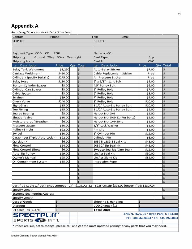
71
Mobile Climbing Tower Manual Rev. 03/11
Appendix A
Auto-Belay/Zip Accessories & Parts Order Form
Item Description Price Qty Total Item Description Price Qty Total
Belay Tank Weldment $1,290 $ Auto-Belay Sticker $7.00 $
Carriage Weldment $450.00 $ Cable Replacement Sticker Free $
Cylinder (Specify Serial #) $275.00 $ Air Pressure Sticker Free $
Belay Hose $130.00 $ 2" x 5/8" - 11nc Bolt $5.00 $
Bottom Cylinder Spacer $3.00 $ 4.5" Pulley Bolt $6.00 $
Cylinder Cart Spacer $3.00 $ 5" Pulley Bolt $7.00 $
Cable Spacer $3.00 $ 6" Pulley Bolt $8.00 $
Strainer $89.00 $ 7" Pulley Bolt $9.00 $
Check Valve $240.00 $ 8" Pulley Bolt $10.00 $
Sight Glass $15.00 $ 8 1/2" Auto-Zip Pulley Bolt $10.00 $
Tee Fitting $85.00 $ 3 1/2" Auto-Zip Pulley Bolt $5.00 $
Sealed Bearing $5.00 $ Nylock Nut 3/4 $2.00 $
Shrader Valve $10.00 $ Nylock Nut 5/8x11 (For bolts) $2.00 $
Moisture-proof Breather $6.00 $ Nylock Nut 1/4x20nc $1.00 $
Pressure Guage $30.00 $ 5/8" Lock Washer $1.00 $
Pulley (6 inch) $22.00 $ Pin Clip $1.00 $
Swivel $60.00 $ 6" Cylinder Pin $12.00 $
Carabineer (Trple Auto-Locking) $22.00 $ Cylinder Pin $6.00 $
Quick Link $6.00 $ 1539 & 1539-1 Seal Kits $45.00 $
Flow Control $54.00 $ 2039 2" Zip Seal Kit $45.00 $
Flow Control Elbow $6.00 $ Sweeco Seal kit (One Seal) $12.00 $
Auto-Zip Pulley $69.00 $ Lin Act Seal Kit $30.00 $
Owner's Manual $25.00 $ Lin Act Gland Kit $85.00 $
Oil Containment System $35.00 $ Inspection Rope $
$ $
$ $
$ $
$ $
$ $
$
$
Cost of Goods Shipping & Handling
Discount COD Charge ($15)
UT Sales Tax (6.37%) Total Due:
* Prices are subject to change, please call and get the most updated pricing for any parts that you may need.
Contact: Phone: Fax: Email:
SHIP TO: BILL TO:
Payment Type: COD CC PO# Name on CC:
Card Type: Exp:Shipping: Ground 2Day 3Day Overnight
Shipping Acct #: Card #: CVC:
3785 N. Hwy. 91 ~ Hyde Park, UT 84318
PH: 888.563.0163 ~ FX: 435.792.3884
Certified Cable w/ both ends crimped: 24' - $195.00; 32' - $235.00; Zip $395.00 (uncertified: $230.00)
Specify Length ______ ______ ______ ______ ______ ______ ______
Extreme Engineering Cables:
Specify Length ______ ______ ______ ______ ______ ______ ______
$
$
$
$
$
$
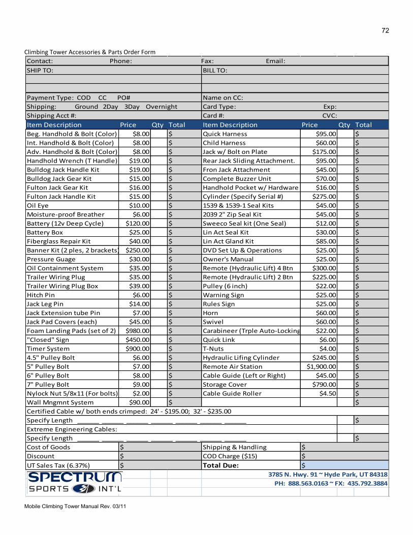
72
Mobile Climbing Tower Manual Rev. 03/11
Climbing Tower Accessories & Parts Order Form
Item Description Price Qty Total Item Description Price Qty Total
Beg. Handhold & Bolt (Color) $8.00 $ Quick Harness $95.00 $
Int. Handhold & Bolt (Color) $8.00 $ Child Harness $60.00 $
Adv. Handhold & Bolt (Color) $8.00 $ Jack w/ Bolt on Plate $175.00 $
Handhold Wrench (T Handle) $19.00 $ Rear Jack Sliding Attachment. $95.00 $
Bulldog Jack Handle Kit $19.00 $ Fron Jack Attachment $45.00 $
Bulldog Jack Gear Kit $15.00 $ Complete Buzzer Unit $70.00 $
Fulton Jack Gear Kit $16.00 $ Handhold Pocket w/ Hardware $16.00 $
Fulton Jack Handle Kit $15.00 $ Cylinder (Specify Serial #) $275.00 $
Oil Eye $10.00 $ 1539 & 1539-1 Seal Kits $45.00 $
Moisture-proof Breather $6.00 $ 2039 2" Zip Seal Kit $45.00 $
Battery (12v Deep Cycle) $120.00 $ Sweeco Seal kit (One Seal) $12.00 $
Battery Box $25.00 $ Lin Act Seal Kit $30.00 $
Fiberglass Repair Kit $40.00 $ Lin Act Gland Kit $85.00 $
Banner Kit (2 ples, 2 brackets) $250.00 $ DVD Set Up & Operations $25.00 $
Pressure Guage $30.00 $ Owner's Manual $25.00 $
Oil Containment System $35.00 $ Remote (Hydraulic Lift) 4 Btn $300.00 $
Trailer Wiring Plug $35.00 $ Remote (Hydraulic Lift) 2 Btn $225.00 $
Trailer Wiring Plug Box $39.00 $ Pulley (6 inch) $22.00 $
Hitch Pin $6.00 $ Warning Sign $25.00 $
Jack Leg Pin $14.00 $ Rules Sign $25.00 $
Jack Extension tube Pin $7.00 $ Horn $60.00 $
Jack Pad Covers (each) $45.00 $ Swivel $60.00 $
Foam Landing Pads (set of 2) $980.00 $ Carabineer (Trple Auto-Locking) $22.00 $
"Closed" Sign $450.00 $ Quick Link $6.00 $
Timer System $900.00 $ T-Nuts $4.00 $
4.5" Pulley Bolt $6.00 $ Hydraulic Lifing Cylinder $245.00 $
5" Pulley Bolt $7.00 $ Remote Air Station $1,900.00 $
6" Pulley Bolt $8.00 $ Cable Guide (Left or Right) $45.00 $
7" Pulley Bolt $9.00 $ Storage Cover $790.00 $
Nylock Nut 5/8x11 (For bolts) $2.00 $ Cable Guide Roller $4.50 $
Wall Mngmnt System $90.00 $ $
$
$
Cost of Goods Shipping & Handling
Discount COD Charge ($15)
UT Sales Tax (6.37%) Total Due:
Contact: Phone: Fax: Email:
SHIP TO: BILL TO:
Payment Type: COD CC PO# Name on CC:
Card Type: Exp:Shipping: Ground 2Day 3Day Overnight
Shipping Acct #: Card #: CVC:
3785 N. Hwy. 91 ~ Hyde Park, UT 84318
PH: 888.563.0163 ~ FX: 435.792.3884
Certified Cable w/ both ends crimped: 24' - $195.00; 32' - $235.00
Specify Length ______ ______ ______ ______ ______ ______ ______
Extreme Engineering Cables:
Specify Length ______ ______ ______ ______ ______ ______ ______
$
$
$
$
$
$
73
Mobile Climbing Tower Manual Rev. 03/11
Appendix B
Changing an Auto-Belay Cylinder
This procedure is for the Generation 4 Auto-Belay design with 4” x 4” tank installed on climbing structure. Two people are recommended.
Tools Required:
Two adjustable wrenches capable to open to 1 ½” or; two - 1 1/2” and one 1 1/8” open end wrenches.
Air chuck.
7/8” open end wrench
9/16” open wrench
ISO 32 oil; the following name brand fluid is available: Mobile DTE – 24, Texaco RANDO – 32, and Chevron AW – 32
Rags to absorb oil
Directions:
1. Pull cable/rope all the way down to bottom of wall panel to fully retract cylinders (3) to force oil from the cylinder tube.
2. Depressurize the Auto-Belay tank (1) entirely. Depress the center of the Schrader valve (15) with a Schrader valve air chuck.
3. Use the wrench to remove 1” nut (5) from 1” bolt (7). Remove 1” bolt (7) on bottom pulley bracket. Keep the spacer (20) from between cylinders on 32’ Auto-Belays to put it back on later.
4. Remove breather (18) from old cylinder and install it on the new cylinder. 5. Use the wrench to remove hose (11) and check valve (20) from cylinder that you are replacing. Loosen
hose fitting then check valve (20), repeat this until the check valve is removed. Now it takes two people, one person to hold a CLEAN rag over the check valve (20) to keep oil from escaping. Oil can be replaced afterwards. The second person can do the nest steps while the other person holds a rag over the check valve.
6. At the top of cylinder (rod end) remove bottom clip from pin so pin may be pulled out. Keep any spacer (19) to reinstall as you put new cylinder on.
7. Cylinder may now be removed. 8. Work backwards from here repeat steps 5 thru 3 to attach new cylinder. 9. Once everything is n place add air to the Auto-Belay tank until the pressure gauge reads 90 psi. The
procedure is the same for 24’ and 32’ walls. 10. Purge the air out of cylinders by repeatedly pulling the rope down and then allow it to rise by hand
until resistance is felt throughout the entire down stroke. Now check oil level. 11. If oil needs to be added to make oil visible in oil lens, repeat step 2. Remove fill plug at top of tank with
a 7/8” wrench or a 5/16” Allen wrench. Add oil then tighten fill plug and repeat step 9. Check oil level again. Repeat if necessary to assure that oil level is in the middle of sight gauge/oil eye.
3785 N. HWY 91 ǀ Hyde Park ǀ Utah 84318 ǀ 888.563.0163
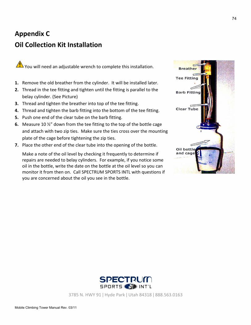
74
Mobile Climbing Tower Manual Rev. 03/11
Appendix C
Oil Collection Kit Installation
You will need an adjustable wrench to complete this installation.
1. Remove the old breather from the cylinder. It will be installed later.
2. Thread in the tee fitting and tighten until the fitting is parallel to the
belay cylinder. (See Picture)
3. Thread and tighten the breather into top of the tee fitting.
4. Thread and tighten the barb fitting into the bottom of the tee fitting.
5. Push one end of the clear tube on the barb fitting.
6. Measure 10 ½” down from the tee fitting to the top of the bottle cage
and attach with two zip ties. Make sure the ties cross over the mounting
plate of the cage before tightening the zip ties.
7. Place the other end of the clear tube into the opening of the bottle.
Make a note of the oil level by checking it frequently to determine if repairs are needed to belay cylinders. For example, if you notice some oil in the bottle, write the date on the bottle at the oil level so you can monitor it from then on. Call SPECTRUM SPORTS INTL with questions if you are concerned about the oil you see in the bottle.
3785 N. HWY 91 ǀ Hyde Park ǀ Utah 84318 ǀ 888.563.0163
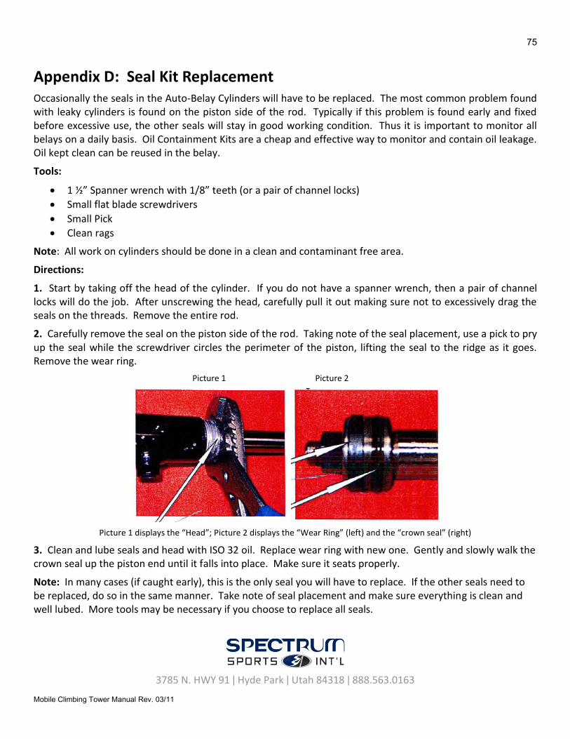
75
Mobile Climbing Tower Manual Rev. 03/11
Appendix D: Seal Kit Replacement
Occasionally the seals in the Auto-Belay Cylinders will have to be replaced. The most common problem found with leaky cylinders is found on the piston side of the rod. Typically if this problem is found early and fixed before excessive use, the other seals will stay in good working condition. Thus it is important to monitor all belays on a daily basis. Oil Containment Kits are a cheap and effective way to monitor and contain oil leakage. Oil kept clean can be reused in the belay.
Tools:
1 ½” Spanner wrench with 1/8” teeth (or a pair of channel locks)
Small flat blade screwdrivers
Small Pick
Clean rags
Note: All work on cylinders should be done in a clean and contaminant free area.
Directions:
1. Start by taking off the head of the cylinder. If you do not have a spanner wrench, then a pair of channel locks will do the job. After unscrewing the head, carefully pull it out making sure not to excessively drag the seals on the threads. Remove the entire rod.
2. Carefully remove the seal on the piston side of the rod. Taking note of the seal placement, use a pick to pry up the seal while the screwdriver circles the perimeter of the piston, lifting the seal to the ridge as it goes. Remove the wear ring.
Picture 1 Picture 2
Picture 1 displays the “Head”; Picture 2 displays the “Wear Ring” (left) and the “crown seal” (right)
3. Clean and lube seals and head with ISO 32 oil. Replace wear ring with new one. Gently and slowly walk the crown seal up the piston end until it falls into place. Make sure it seats properly.
Note: In many cases (if caught early), this is the only seal you will have to replace. If the other seals need to be replaced, do so in the same manner. Take note of seal placement and make sure everything is clean and well lubed. More tools may be necessary if you choose to replace all seals.
3785 N. HWY 91 ǀ Hyde Park ǀ Utah 84318 ǀ 888.563.0163
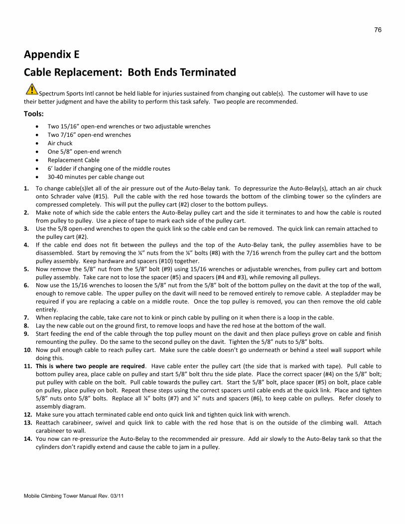
76
Mobile Climbing Tower Manual Rev. 03/11
Appendix E
Cable Replacement: Both Ends Terminated
Spectrum Sports Intl cannot be held liable for injuries sustained from changing out cable(s). The customer will have to use their better judgment and have the ability to perform this task safely. Two people are recommended.
Tools:
Two 15/16” open-end wrenches or two adjustable wrenches
Two 7/16” open-end wrenches
Air chuck
One 5/8” open-end wrench
Replacement Cable
6’ ladder if changing one of the middle routes
30-40 minutes per cable change out
1. To change cable(s)let all of the air pressure out of the Auto-Belay tank. To depressurize the Auto-Belay(s), attach an air chuck onto Schrader valve (#15). Pull the cable with the red hose towards the bottom of the climbing tower so the cylinders are compressed completely. This will put the pulley cart (#2) closer to the bottom pulleys.
2. Make note of which side the cable enters the Auto-Belay pulley cart and the side it terminates to and how the cable is routed from pulley to pulley. Use a piece of tape to mark each side of the pulley cart.
3. Use the 5/8 open-end wrenches to open the quick link so the cable end can be removed. The quick link can remain attached to the pulley cart (#2).
4. If the cable end does not fit between the pulleys and the top of the Auto-Belay tank, the pulley assemblies have to be disassembled. Start by removing the ¼” nuts from the ¼” bolts (#8) with the 7/16 wrench from the pulley cart and the bottom pulley assembly. Keep hardware and spacers (#10) together.
5. Now remove the 5/8” nut from the 5/8” bolt (#9) using 15/16 wrenches or adjustable wrenches, from pulley cart and bottom pulley assembly. Take care not to lose the spacer (#5) and spacers (#4 and #3), while removing all pulleys.
6. Now use the 15/16 wrenches to loosen the 5/8” nut from the 5/8” bolt of the bottom pulley on the davit at the top of the wall, enough to remove cable. The upper pulley on the davit will need to be removed entirely to remove cable. A stepladder may be required if you are replacing a cable on a middle route. Once the top pulley is removed, you can then remove the old cable entirely.
7. When replacing the cable, take care not to kink or pinch cable by pulling on it when there is a loop in the cable. 8. Lay the new cable out on the ground first, to remove loops and have the red hose at the bottom of the wall. 9. Start feeding the end of the cable through the top pulley mount on the davit and then place pulleys grove on cable and finish
remounting the pulley. Do the same to the second pulley on the davit. Tighten the 5/8” nuts to 5/8” bolts. 10. Now pull enough cable to reach pulley cart. Make sure the cable doesn’t go underneath or behind a steel wall support while
doing this. 11. This is where two people are required. Have cable enter the pulley cart (the side that is marked with tape). Pull cable to
bottom pulley area, place cable on pulley and start 5/8” bolt thru the side plate. Place the correct spacer (#4) on the 5/8” bolt; put pulley with cable on the bolt. Pull cable towards the pulley cart. Start the 5/8” bolt, place spacer (#5) on bolt, place cable on pulley, place pulley on bolt. Repeat these steps using the correct spacers until cable ends at the quick link. Place and tighten 5/8” nuts onto 5/8” bolts. Replace all ¼” bolts (#7) and ¼” nuts and spacers (#6), to keep cable on pulleys. Refer closely to assembly diagram.
12. Make sure you attach terminated cable end onto quick link and tighten quick link with wrench. 13. Reattach carabineer, swivel and quick link to cable with the red hose that is on the outside of the climbing wall. Attach
carabineer to wall. 14. You now can re-pressurize the Auto-Belay to the recommended air pressure. Add air slowly to the Auto-Belay tank so that the
cylinders don’t rapidly extend and cause the cable to jam in a pulley.
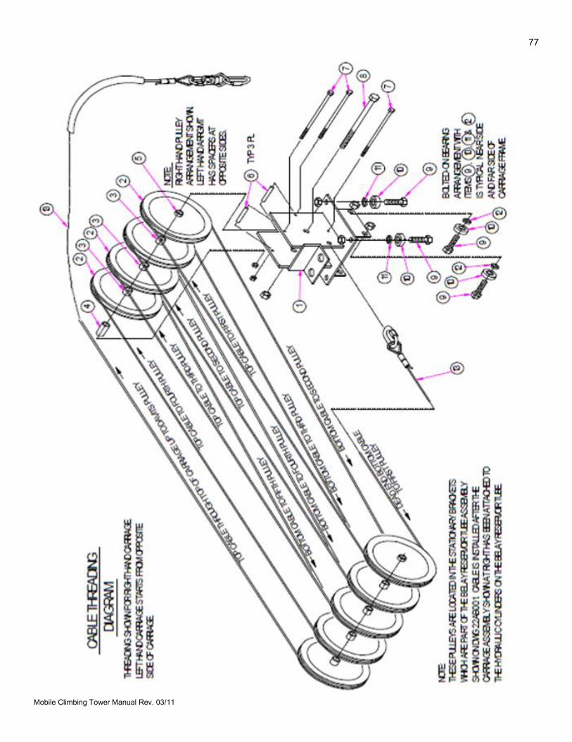
77
Mobile Climbing Tower Manual Rev. 03/11
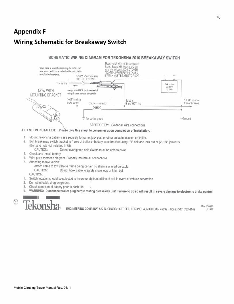
78
Mobile Climbing Tower Manual Rev. 03/11
Appendix F
Wiring Schematic for Breakaway Switch
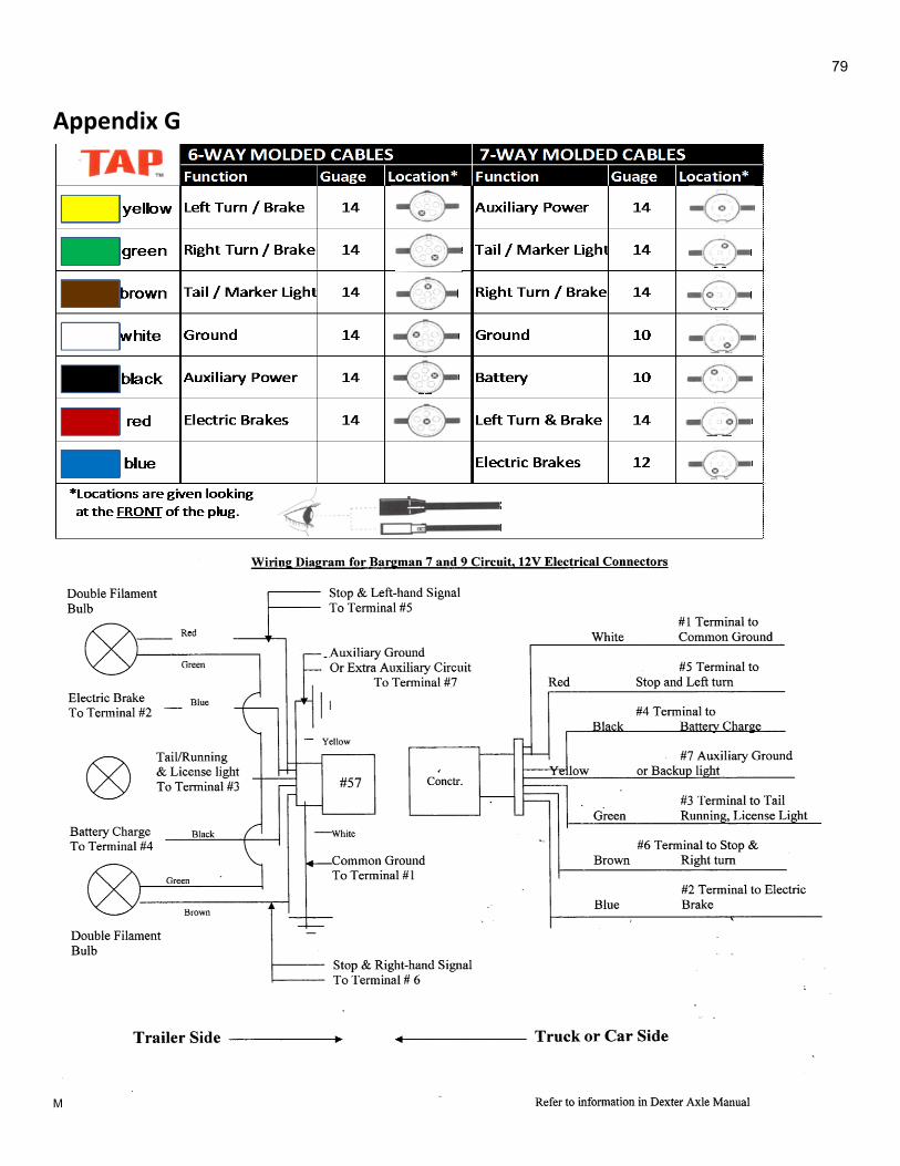
79
Mobile Climbing Tower Manual Rev. 03/11
Appendix G
80
Mobile Climbing Tower Manual Rev. 03/11
Appendix H
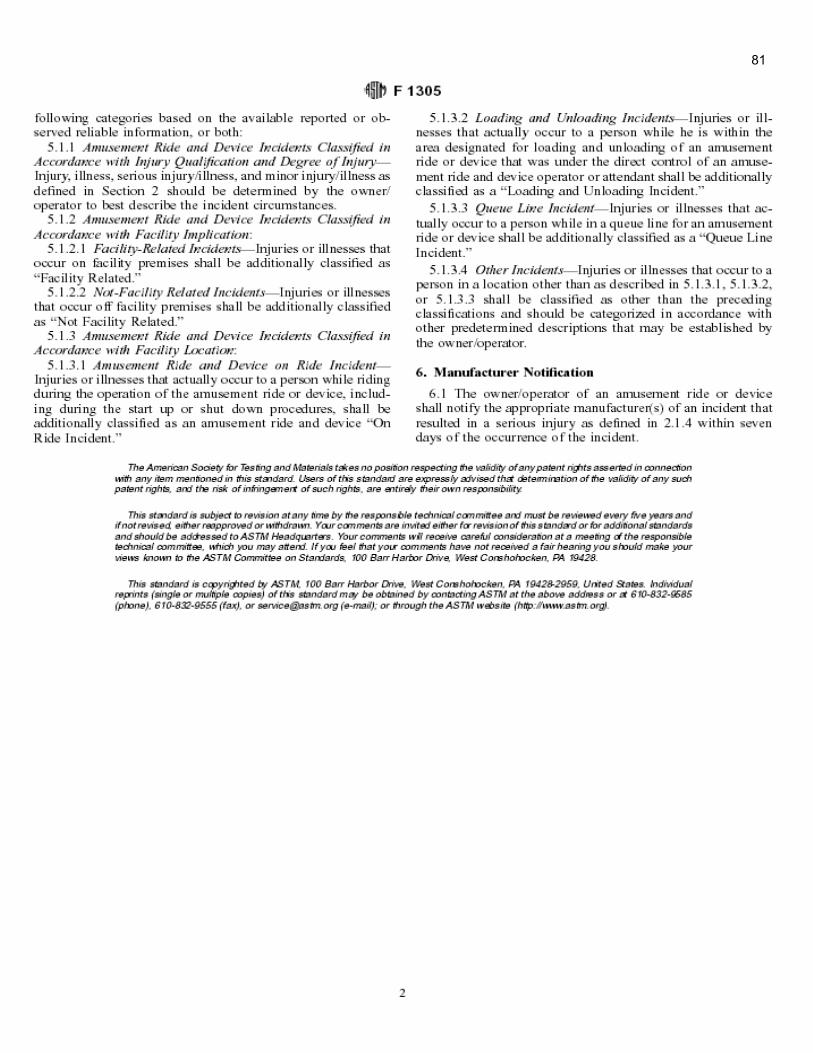
81
Mobile Climbing Tower Manual Rev. 03/11
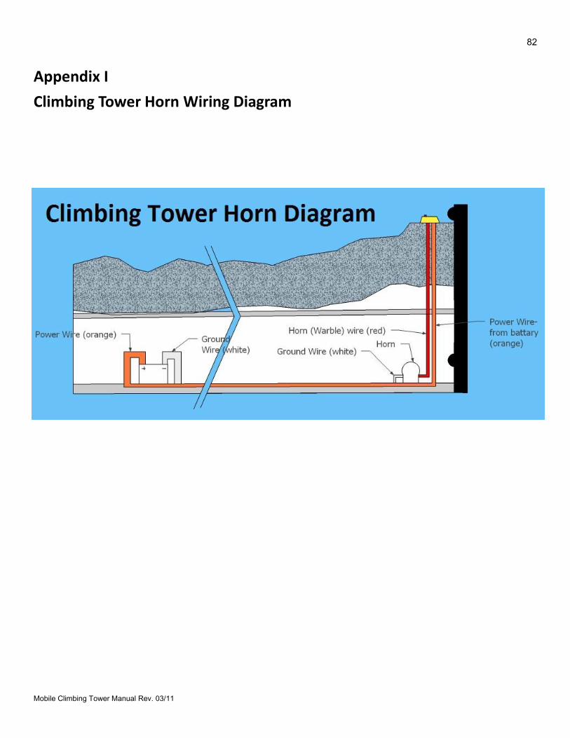
82
Mobile Climbing Tower Manual Rev. 03/11
Appendix I
Climbing Tower Horn Wiring Diagram
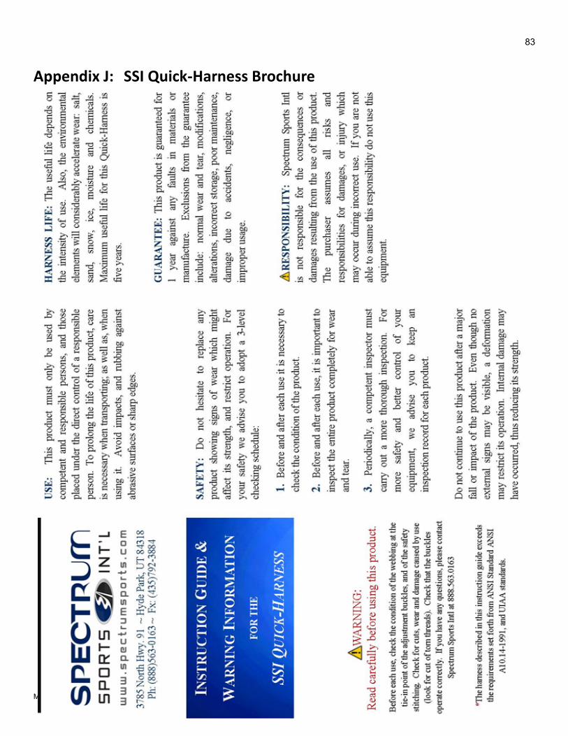
83
Mobile Climbing Tower Manual Rev. 03/11
Appendix J: SSI Quick-Harness Brochure
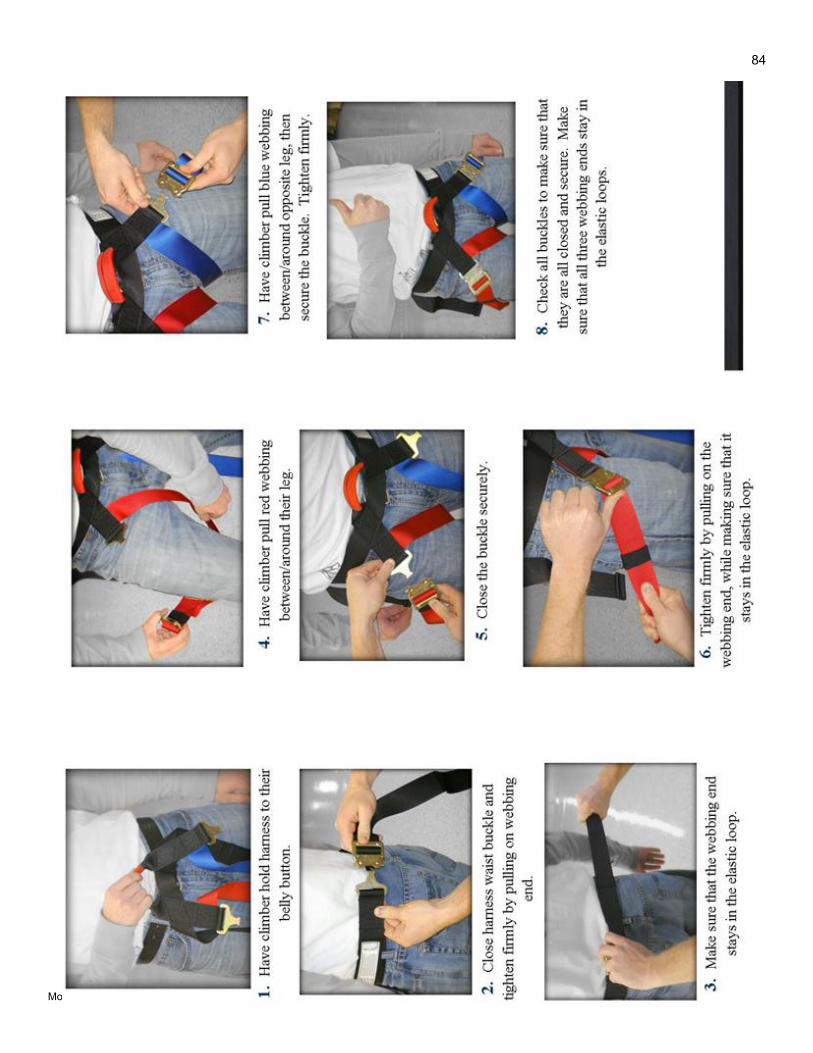
84
Mobile Climbing Tower Manual Rev. 03/11