Embed Size (px)
Citation preview
BIOMECHANIC SIGNAL FILTERING FOR DYNAMIC ANALYSIS PURPOSE: A QUANTITATIVE COMPARISON
BETWEEN DIFFERENT METHODS R. Far.&Rezai and E. Shwedyk
Department of Electrical and Computer Engineering, The University of Manitoba, Winnipeg, Manitoba R3T 2N2, Canada
INTRODUCTION: Kinetic analysis requires the kinematic data to be differentiated, an operation that is extremely noise sensitive. Thus the data should be filtered with a filter which has two conflicting objet-tives: removing the noise and preserving the signal [I]. Here four methods, Butterworth filter, polynomial curve fitting, median filter and the spline smoothing technique [2], are corn-pared. It is shown that using the first three methods only one goal can be achieved, but with the spline smoothing method not only is the noise substantially filtered, but also the sig-nal is well preserved. METHODS: To compare the four methods, a representative test signal (Fig. I). its 1st and 2nd derivatives were used. Then noise was added to the test signal. Two different noise signals were considered, uniform and Gaussian, each at three dif-ferent signal to noise ratios, 7dB. lOdB, 13dB. The resultant signal was filtered using the four different approaches and compared with the test signal in three levels; raw (position), 1st derivative (vrlocitv) and 2nd derivative(accel-eration) of the signal.
I 1 ?l 2* 31 41 51 61 79 81
Fig. 1. Test signal. RESULTS AND CONCLUSION: The results are shown in Fig. 2. All methods perform well for position. However. when results of comparison of rhe velocity and accel-eration are considered, the spline method is considerately better. Therefore it is the most appropriate technique for <moothing and differ-entiation of the biomechanical data.
!
: i.. . . _ _- .
I--.-
waifm GIusJim
Rg.2. Coxtqmiso~~ of tke four methods. _-..__..” ._ ~ .._ ..^ _.......-..I --..l_ --I
REFERENCES: I. R. Fazel-Rezai et al.. Proceeding of CMBE Conference, 32-33, Toronto, Canada, 1997. 2. H. J. Woltring, Human Movement Sci., 4.229-245, 1985. CORRESPONDENCE: Reza Fazel-Rezai, Dept. of Elec. & Comp., Eng., University of Manitoba. Winnipeg, MB, R3T 2N2, Canada, Tel:(204) 474 7038. Fax: (204) 261 4639, [email protected]
PD61
ON THE IMPORTANCE OF PRECISE METHODS OF CALCULATION, APPLICATION TO THE KNEE TORQUES
F. Marin, N. Maurel. A. Diop, F. Lavaste Labontoire de BioM&anique, ENSAM Paris
INTRODUCTION: Traditionally, in science, primarily obtained results and graphs are compared to earlier studies. The main difficulty is then to
distinguish results on the base of their calculation methods. This is also the case of knee torque calculation. Thus, the aim of this study is to enlighten the influence of this last two elements on values of knee joint torques.
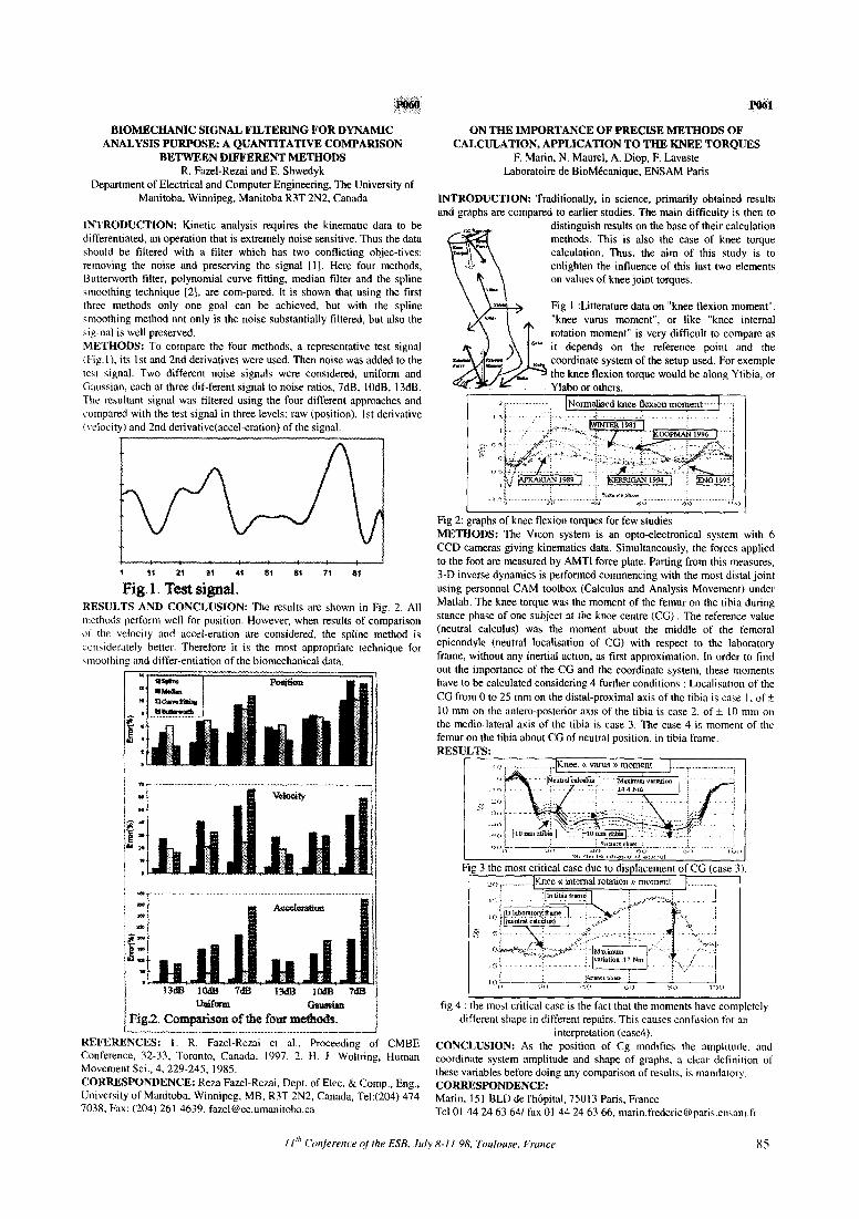
Fig 1 :Litterature data on “knee flexion moment”, “knee varus moment”, or like “knee internal rotation moment” is very difficult to compare as
my* it depends on the reference point and the coordinate system of the setup used. For exemple the knee flexion torque would be along Ytibia, or Ylabo or others.
Norma&d knee flexion rnomen~~~~~~ “.’ 1
,,
- ‘C’ ” ..& i *.tmcr Ph..
” is >B> > *<i.
Fig 2: graphs of knee flexiou torques for few studies METHODS: The Vicon system is an opto-electronical system with 6 CCD cameras giving kinematics data. Simultaneously, the forces applied to the foot are measured by AMTI force plate. Parting from this measures, 3-D inverse dynamics is performed commencing with the most distal joint using personnal CAM toolbox (Calculus and Analysis Movement) under Matlab. The knee torque was the moment of the femur on the tibia during stance phase of one subject at the knee centre (CC) The reference value (neutral calculus) was the moment about the middle of the femoral epicondyle (neutral localisation of CG) with respect to the laboratory frame, without any inertial action, as tirst approximation. In order to find out the importance of the CG and the coordinate system, these moments have to be calculated considering 4 further conditions : Localisation of the CG from 0 to 25 mm on the distal-proximal axis of the tibia is case I. of + IO mm on the antero-posterior axis of the tibia is case 2, of + IO mm on the medio-lateral axis of the tibia is case 3. The case 4 is moment of the femur on the tibia about CG of neutral position. in tibia frame. RESULTS:
Fig 3 the most critical case due to displacement of CG (case 3 1.
iig 4 : the most critical case is the fact that the moments have completely different shape in different repairs. This causes confusion for an
interpretation (case4). CONCLUSION: As the position of Cg modifies the amplitude. and coordinate system amplitude and shape of graphs, a clear definition of these variables before doing any comparison of results, is mandatory. CORRESPONDENCE: Marin. 151 BLD de l’hapital, 75013 Paris, France Tel 01 44 24 63 641 fax 01 44 24 63 66, [email protected]