Embed Size (px)
Citation preview
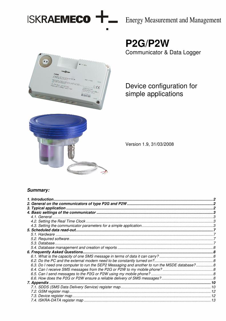
Energy Measurement and Management
Summary: 1. Introduction........................................................................................................................................................2 2. General on the communicators of type P2G and P2W..................................................................................2 3. Typical application ............................................................................................................................................2 4. Basic settings of the communicator ...............................................................................................................3
4.1. General .........................................................................................................................................................3 4.2. Setting the Real Time Clock .........................................................................................................................3 4.3. Setting the communicator parameters for a simple application....................................................................3
5. Scheduled data read-out...................................................................................................................................7 5.1. Hardware ......................................................................................................................................................7 5.2. Required software.........................................................................................................................................7 5.3. Database.......................................................................................................................................................7 5.4. Database management and creation of reports ...........................................................................................8
6. Frequently Asked Questions............................................................................................................................8 6.1. What is the capacity of one SMS message in terms of data it can carry? ...................................................8 6.2. Do the PC and the external modem need to be constantly turned on?........................................................8 6.3. Do I need one computer to run the SEP2 Messaging and another to run the MSDE database? ................8 6.4. Can I receive SMS messages from the P2G or P2W to my mobile phone? ................................................8 6.5. Can I send messages to the P2G or P2W using my mobile phone? ...........................................................8 6.6. How does the P2G or P2W ensure a reliable delivery of SMS messages? .................................................8
7. Appendix ..........................................................................................................................................................10 7.1. SDDS (SMS Data Delivery Service) register map......................................................................................10 7.2. GSM register map.......................................................................................................................................12 7.3. Device register map ....................................................................................................................................12 7.4. ISKRA-DATA register map .........................................................................................................................13
P2G/P2W Communicator & Data Logger
Device configuration for simple applications Version 1.9, 31/03/2008
2
P2G/W � Communicator & Data Logger
1. Introduction The Communicators & Data Loggers of the type P2G and P2W make part of the Automatic Meter Reading (AMR) system of Iskraemeco. Remote reading of data from the device is performed by means of an integrated GSM modem and SMP (SMS Metering Protocol) communication protocol. The requested data can be transmitted either automatically according to a preset time schedule or on demand. The collection of data, the management of the database and the creation of reports is performed by the SEP2W or SEP2Lite program package supplied by Iskraemeco. This document contains the instructions how to configure the device in the case of a simple application where a scheduled reading of the load profile of one pulse input and of the temperature profile is performed.
2. General on the communicators of type P2G and P2W The P2G Communicator & Data Logger is available in three different versions according to the number of pulse inputs and according to the type of protection needed for potentially explosive environments. The P2W Communicator & Data Logger is available in one version only.
Type Pulse inputs Pulse outputs Protection P2G-K17V03I00 4 inputs
(2 pulse inputs, 2 »tamper« inputs) 2 outputs
P2G-K17V03I01 4 pulse inputs 4 outputs
Intrinsic safety with the type of protection »ia« (pulse inputs
only).The unit must be installed in the safe area but can be
connected to a device in the hazardous area
P2G-K17V03I00-IS 4 inputs (2 pulse inputs, 2 »tamper« inputs)
2 outputs Intrinsic safety with the type of protection »ia«.
The unit can be installed in the hazardous area.
P2W-K17V02 2 pulse inputs - -
Table 1. Available P2G and P2W types In the remaining text of this document the different types of P2G and P2W Communicator & Data Logger will be designated shortly as »communicator«.
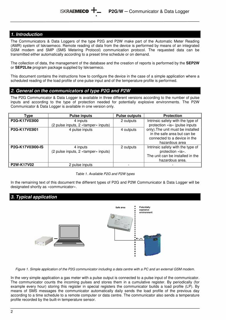
3. Typical application
Figure 1. Simple application of the P2G communicator including a data centre with a PC and an external GSM modem. In the very simple application a gas meter with a pulse output is connected to a pulse input of the communicator. The communicator counts the incoming pulses and stores them in a cumulative register. By periodically (for example every hour) storing this register in special registers the communicator builds a load profile (LP). By means of SMS messages the communicator automatically daily sends the load profile of the previous day according to a time schedule to a remote computer or data centre. The communicator also sends a temperature profile recorded by the built-in temperature sensor.
3
P2G/W � Communicator & Data Logger
4. Basic settings of the communicator
4.1. General
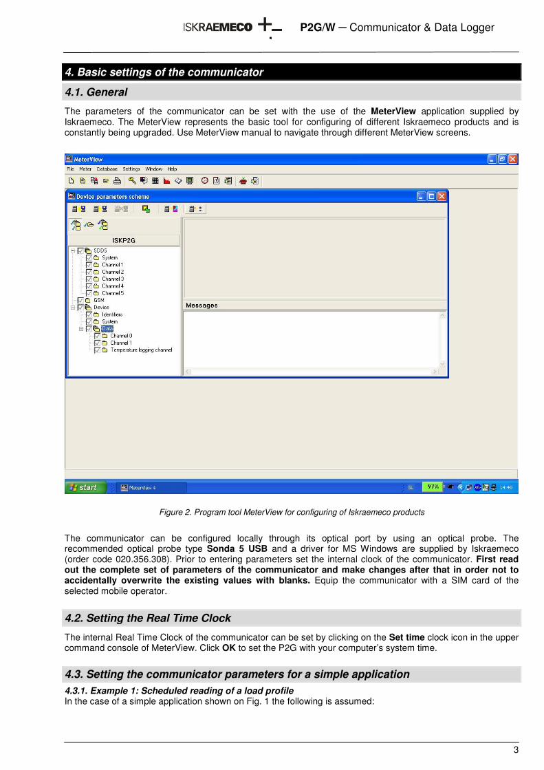
The parameters of the communicator can be set with the use of the MeterView application supplied by Iskraemeco. The MeterView represents the basic tool for configuring of different Iskraemeco products and is constantly being upgraded. Use MeterView manual to navigate through different MeterView screens.
Figure 2. Program tool MeterView for configuring of Iskraemeco products
The communicator can be configured locally through its optical port by using an optical probe. The recommended optical probe type Sonda 5 USB and a driver for MS Windows are supplied by Iskraemeco (order code 020.356.308). Prior to entering parameters set the internal clock of the communicator. First read out the complete set of parameters of the communicator and make changes after that in order not to accidentally overwrite the existing values with blanks. Equip the communicator with a SIM card of the selected mobile operator.
4.2. Setting the Real Time Clock
The internal Real Time Clock of the communicator can be set by clicking on the Set time clock icon in the upper command console of MeterView. Click OK to set the P2G with your computer’s system time. 4.3. Setting the communicator parameters for a simple application 4.3.1. Example 1: Scheduled reading of a load profile In the case of a simple application shown on Fig. 1 the following is assumed:
4
P2G/W � Communicator & Data Logger
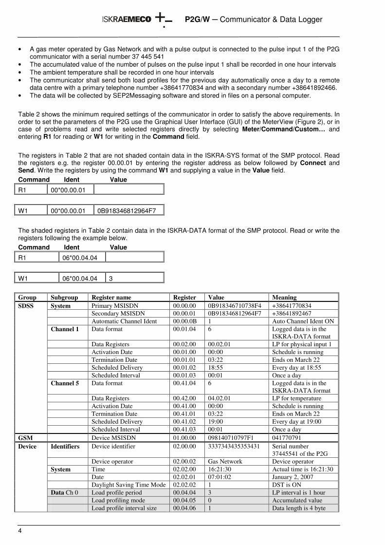
• A gas meter operated by Gas Network and with a pulse output is connected to the pulse input 1 of the P2G communicator with a serial number 37 445 541
• The accumulated value of the number of pulses on the pulse input 1 shall be recorded in one hour intervals • The ambient temperature shall be recorded in one hour intervals • The communicator shall send both load profiles for the previous day automatically once a day to a remote
data centre with a primary telephone number +38641770834 and with a secondary number +38641892466. • The data will be collected by SEP2Messaging software and stored in files on a personal computer. Table 2 shows the minimum required settings of the communicator in order to satisfy the above requirements. In order to set the parameters of the P2G use the Graphical User Interface (GUI) of the MeterView (Figure 2), or in case of problems read and write selected registers directly by selecting Meter/Command/Custom… and entering R1 for reading or W1 for writing in the Command field. The registers in Table 2 that are not shaded contain data in the ISKRA-SYS format of the SMP protocol. Read the registers e.g. the register 00.00.01 by entering the register address as below followed by Connect and Send. Write the registers by using the command W1 and supplying a value in the Value field. Command Ident Value
R1 00*00.00.01
W1 00*00.00.01 0B918346812964F7
The shaded registers in Table 2 contain data in the ISKRA-DATA format of the SMP protocol. Read or write the registers following the example below. Command Ident Value
R1 06*00.04.04
W1 06*00.04.04 3
Group Subgroup Register name Register Value Meaning
System Primary MSISDN 00.00.00 0B918346710738F4 +38641770834 Secondary MSISDN 00.00.01 0B918346812964F7 +38641892467 Automatic Channel Ident 00.00.0B 1 Auto Channel Ident ON Channel 1 Data format 00.01.04 6 Logged data is in the
ISKRA-DATA format Data Registers 00.02.00 00.02.01 LP for physical input 1 Activation Date 00.01.00 00:00 Schedule is running Termination Date 00.01.01 03:22 Ends on March 22 Scheduled Delivery 00.01.02 18:55 Every day at 18:55 Scheduled Interval 00.01.03 00:01 Once a day Channel 5 Data format 00.41.04 6 Logged data is in the
ISKRA-DATA format Data Registers 00.42.00 04.02.01 LP for temperature Activation Date 00.41.00 00:00 Schedule is running Termination Date 00.41.01 03:22 Ends on March 22 Scheduled Delivery 00.41.02 19:00 Every day at 19:00
SDSS
Scheduled Interval 00.41.03 00:01 Once a day GSM Device MSISDN 01.00.00 098140710797F1 041770791
Identifiers Device identifier 02.00.00 3337343435353431 Serial number 37445541 of the P2G
Device operator 02.00.02 Gas Network Device operator System Time 02.02.00 16:21:30 Actual time is 16:21:30 Date 02.02.01 07:01:02 January 2, 2007 Daylight Saving Time Mode 02.02.02 1 DST is ON Data Ch 0 Load profile period 00.04.04 3 LP interval is 1 hour Load profiling mode 00.04.05 0 Accumulated value
Device
Load profile interval size 00.04.06 1 Data length is 4 byte
5
P2G/W � Communicator & Data Logger
Data Temp Load profile period 04.04.04 3 LP interval is 1 hour
Table 2. Example settings of the P2G registers for the P2G-K17V03I01 version
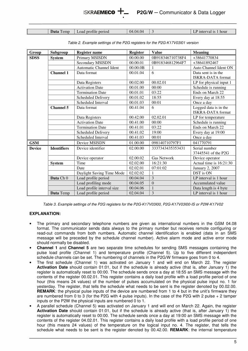
Group Subgroup Register name Register Value Meaning
System Primary MSISDN 00.00.00 0B918346710738F4 +38641770834 Secondary MSISDN 00.00.01 0B918346812964F7 +38641892467 Automatic Channel Ident 00.00.0B 1 Auto Channel Ident ON Channel 1 Data format 00.01.04 6 Data sent is in the
ISKRA-DATA format Data Registers 00.02.00 00.02.01 LP for physical input 1 Activation Date 00.01.00 00:00 Schedule is running Termination Date 00.01.01 03:22 Ends on March 22 Scheduled Delivery 00.01.02 18:55 Every day at 18:55 Scheduled Interval 00.01.03 00:01 Once a day Channel 5 Data format 00.41.04 6 Logged data is in the
ISKRA-DATA format Data Registers 00.42.00 02.02.01 LP for temperature Activation Date 00.41.00 00:00 Schedule is running Termination Date 00.41.01 03:22 Ends on March 22 Scheduled Delivery 00.41.02 19:00 Every day at 19:00
SDSS
Scheduled Interval 00.41.03 00:01 Once a day GSM Device MSISDN 01.00.00 098140710797F1 041770791
Identifiers Device identifier 02.00.00 3337343435353431 Serial number 37445541 of the P2G
Device operator 02.00.02 Gas Network Device operator System Time 02.02.00 16:21:30 Actual time is 16:21:30 Date 02.02.01 07:01:02 January 2, 2007 Daylight Saving Time Mode 02.02.02 1 DST is ON Data Ch 0 Load profile period 00.04.04 3 LP interval is 1 hour Load profiling mode 00.04.05 0 Accumulated value Load profile interval size 00.04.06 1 Data length is 4 byte
Device
Data Temp Load profile period 02.04.04 3 LP interval is 1 hour
Table 3. Example settings of the P2G registers for the P2G-K17V03I00, P2G-K17V03I00-IS or P2W-K17V02
EXPLANATION: • The primary and secondary telephone numbers are given as international numbers in the GSM 04.08
format. The communicator sends data always to the primary number but receives remote configuring or read-out commands from both numbers. Automatic channel identification is enabled (data in an SMS message will be preceded by the schedule channel number). Active alarm mode and active error mode should normally be disabled.
• Channel 1 and Channel 5 are two separate time schedules for sending SMS messages containing the pulse load profile (Channel 1) and temperature profile (Channel 5). Up to five different independent schedule channels can be set. The numbering of channels in the P2G/W firmware goes from 0 to 4.
• The first schedule (Channel 1) was activated on January 1 and will end on March 22. The register Activation Date should contain 01:01, but if the schedule is already active (that is, after January 1) the register is automatically reset to 00:00. The schedule sends once a day at 18:55 an SMS message with the contents of the register 00.02.01. This register contains a daily load profile with a load profile period of one hour (this means 24 values) of the number of pulses accumulated on the physical pulse input no. 1 for yesterday. The register, that tells the schedule what needs to be sent is the register denoted by 00.02.00. REMARK: the physical pulse inputs of the device are numbered from 1 to 4 but in the unit’s firmware they are numbered from 0 to 3 (for the P2G with 4 pulse inputs). In the case of the P2G with 2 pulse + 2 tamper inputs or the P2W the physical inputs are numbered 0 to 1.
• A parallel schedule (Channel 5) was activated on January 1 and will end on March 22. Again, the register Activation Date should contain 01:01, but if the schedule is already active (that is, after January 1) the register is automatically reset to 00:00. The schedule sends once a day at 19:00 an SMS message with the contents of the register 04.02.01. This register contains a daily load profile with a load profile period of one hour (this means 24 values) of the temperature on the logical input no. 4. The register, that tells the schedule what needs to be sent is the register denoted by 00.42.00. REMARK: the internal temperature
6
P2G/W � Communicator & Data Logger
sensor of the unit is connected to a logical channel of which the number follows the number of the last physical channel and is therefore equal to 4 (for the P2G with 4 pulse inputs). In the case of the P2G with 2 pulse + 2 tamper inputs or the P2W the number of the logical channel is 2.
• The scheduled data are preceded by the number of the schedule channel (Automatic Channel Identification)
• The device telephone number is given as a national number in the GSM 04.08 format. • The digits of the device identifier are transferred as ASCII characters. The serial number 37445541 is
therefore stored as 3337343435353431. • The load profile period for the pulse input is 1 hour (4→24 hours, 3→1 hour, 2→30 minutes, 1→15 minutes,
0→5 minutes), the cumulated value is recorded (0→accumulated, 1→differential) and each value is 4 bytes in length (0→2 bytes, 1→4 bytes). With the temperature load profile only the load profile period can be set.
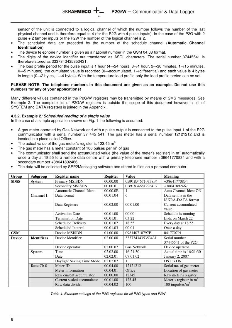
PLEASE NOTE: The telephone numbers in this document are given as an example. Do not use this numbers for any of your applications! Many different values contained in the P2G/W registers may be transmitted by means of SMS messages. See Example 2. The complete list of P2G/W registers is outside the scope of this document however a list of SYSTEM and DATA registers is joined in the Appendix. 4.3.2. Example 2: Scheduled reading of a single value In the case of a simple application shown on Fig. 1 the following is assumed: • A gas meter operated by Gas Network and with a pulse output is connected to the pulse input 1 of the P2G
communicator with a serial number 37 445 541. The gas meter has a serial number 12121212 and is located in a place called Office.
• The actual value of the gas meter’s register is 123.45 m3 • The gas meter has a meter constant of 100 pulses per m3 of gas • The communicator shall send the accumulated value (the value of the meter’s register) in m3 automatically
once a day at 18:55 to a remote data centre with a primary telephone number +38641770834 and with a secondary number +38641892466.
• The data will be collected by SEP2Messaging software and stored in files on a personal computer. Group Subgroup Register name Register Value Meaning
System Primary MSISDN 00.00.00 0B918346710738F4 +38641770834 Secondary MSISDN 00.00.01 0B918346812964F7 +38641892467 Automatic Channel Ident 00.00.0B 1 Auto Channel Ident ON Channel 1 Data format 00.01.04 6 Data sent is in the
ISKRA-DATA format Data Registers 00.02.00 00.01.00 Current accumulated
value Activation Date 00.01.00 00:00 Schedule is running Termination Date 00.01.01 03:22 Ends on March 22 Scheduled Delivery 00.01.02 18:55 Every day at 18:55
SDSS
Scheduled Interval 00.01.03 00:01 Once a day GSM Device MSISDN 01.00.00 098140710797F1 041770791
Identifiers Device identifier 02.00.00 3337343435353431 Serial number 37445541 of the P2G
Device operator 02.00.02 Gas Network Device operator System Time 02.02.00 16:21:30 Actual time is 16:21:30 Date 02.02.01 07:01:02 January 2, 2007 Daylight Saving Time Mode 02.02.02 1 DST is ON Data Ch 0 Meter ID 00.04.00 12121212 Serial no. of gas meter Meter information 00.04.01 Office Location of gas meter Raw current accumulator 00.00.00 12345 Raw meter’s register Current scaled accumulator 00.01.00 123.45 Meter’s register in m3
Device
Raw data divider 00.04.02 100 100 impulses/m3
Table 4. Example settings of the P2G registers for all P2G types and P2W
7
P2G/W � Communicator & Data Logger
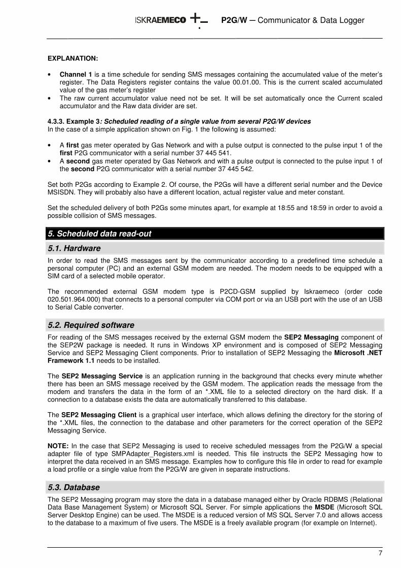
EXPLANATION: • Channel 1 is a time schedule for sending SMS messages containing the accumulated value of the meter’s
register. The Data Registers register contains the value 00.01.00. This is the current scaled accumulated value of the gas meter’s register
• The raw current accumulator value need not be set. It will be set automatically once the Current scaled accumulator and the Raw data divider are set.
4.3.3. Example 3: Scheduled reading of a single value from several P2G/W devices In the case of a simple application shown on Fig. 1 the following is assumed: • A first gas meter operated by Gas Network and with a pulse output is connected to the pulse input 1 of the
first P2G communicator with a serial number 37 445 541. • A second gas meter operated by Gas Network and with a pulse output is connected to the pulse input 1 of
the second P2G communicator with a serial number 37 445 542. Set both P2Gs according to Example 2. Of course, the P2Gs will have a different serial number and the Device MSISDN. They will probably also have a different location, actual register value and meter constant. Set the scheduled delivery of both P2Gs some minutes apart, for example at 18:55 and 18:59 in order to avoid a possible collision of SMS messages.
5. Scheduled data read-out
5.1. Hardware In order to read the SMS messages sent by the communicator according to a predefined time schedule a personal computer (PC) and an external GSM modem are needed. The modem needs to be equipped with a SIM card of a selected mobile operator. The recommended external GSM modem type is P2CD-GSM supplied by Iskraemeco (order code 020.501.964.000) that connects to a personal computer via COM port or via an USB port with the use of an USB to Serial Cable converter.
5.2. Required software For reading of the SMS messages received by the external GSM modem the SEP2 Messaging component of the SEP2W package is needed. It runs in Windows XP environment and is composed of SEP2 Messaging Service and SEP2 Messaging Client components. Prior to installation of SEP2 Messaging the Microsoft .NET Framework 1.1 needs to be installed. The SEP2 Messaging Service is an application running in the background that checks every minute whether there has been an SMS message received by the GSM modem. The application reads the message from the modem and transfers the data in the form of an *.XML file to a selected directory on the hard disk. If a connection to a database exists the data are automatically transferred to this database. The SEP2 Messaging Client is a graphical user interface, which allows defining the directory for the storing of the *.XML files, the connection to the database and other parameters for the correct operation of the SEP2 Messaging Service. NOTE: In the case that SEP2 Messaging is used to receive scheduled messages from the P2G/W a special adapter file of type SMPAdapter_Registers.xml is needed. This file instructs the SEP2 Messaging how to interpret the data received in an SMS message. Examples how to configure this file in order to read for example a load profile or a single value from the P2G/W are given in separate instructions.
5.3. Database The SEP2 Messaging program may store the data in a database managed either by Oracle RDBMS (Relational Data Base Management System) or Microsoft SQL Server. For simple applications the MSDE (Microsoft SQL Server Desktop Engine) can be used. The MSDE is a reduced version of MS SQL Server 7.0 and allows access to the database to a maximum of five users. The MSDE is a freely available program (for example on Internet).
8
P2G/W � Communicator & Data Logger
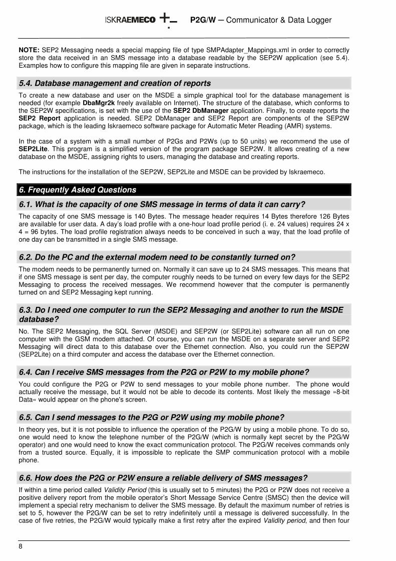
NOTE: SEP2 Messaging needs a special mapping file of type SMPAdapter_Mappings.xml in order to correctly store the data received in an SMS message into a database readable by the SEP2W application (see 5.4). Examples how to configure this mapping file are given in separate instructions.
5.4. Database management and creation of reports To create a new database and user on the MSDE a simple graphical tool for the database management is needed (for example DbaMgr2k freely available on Internet). The structure of the database, which conforms to the SEP2W specifications, is set with the use of the SEP2 DbManager application. Finally, to create reports the SEP2 Report application is needed. SEP2 DbManager and SEP2 Report are components of the SEP2W package, which is the leading Iskraemeco software package for Automatic Meter Reading (AMR) systems. In the case of a system with a small number of P2Gs and P2Ws (up to 50 units) we recommend the use of SEP2Lite. This program is a simplified version of the program package SEP2W. It allows creating of a new database on the MSDE, assigning rights to users, managing the database and creating reports. The instructions for the installation of the SEP2W, SEP2Lite and MSDE can be provided by Iskraemeco.
6. Frequently Asked Questions
6.1. What is the capacity of one SMS message in terms of data it can carry? The capacity of one SMS message is 140 Bytes. The message header requires 14 Bytes therefore 126 Bytes are available for user data. A day’s load profile with a one-hour load profile period (i. e. 24 values) requires 24 x 4 = 96 bytes. The load profile registration always needs to be conceived in such a way, that the load profile of one day can be transmitted in a single SMS message.
6.2. Do the PC and the external modem need to be constantly turned on? The modem needs to be permanently turned on. Normally it can save up to 24 SMS messages. This means that if one SMS message is sent per day, the computer roughly needs to be turned on every few days for the SEP2 Messaging to process the received messages. We recommend however that the computer is permanently turned on and SEP2 Messaging kept running.
6.3. Do I need one computer to run the SEP2 Messaging and another to run the MSDE database? No. The SEP2 Messaging, the SQL Server (MSDE) and SEP2W (or SEP2Lite) software can all run on one computer with the GSM modem attached. Of course, you can run the MSDE on a separate server and SEP2 Messaging will direct data to this database over the Ethernet connection. Also, you could run the SEP2W (SEP2Lite) on a third computer and access the database over the Ethernet connection.
6.4. Can I receive SMS messages from the P2G or P2W to my mobile phone? You could configure the P2G or P2W to send messages to your mobile phone number. The phone would actually receive the message, but it would not be able to decode its contents. Most likely the message »8-bit Data« would appear on the phone's screen.
6.5. Can I send messages to the P2G or P2W using my mobile phone? In theory yes, but it is not possible to influence the operation of the P2G/W by using a mobile phone. To do so, one would need to know the telephone number of the P2G/W (which is normally kept secret by the P2G/W operator) and one would need to know the exact communication protocol. The P2G/W receives commands only from a trusted source. Equally, it is impossible to replicate the SMP communication protocol with a mobile phone.
6.6. How does the P2G or P2W ensure a reliable delivery of SMS messages? If within a time period called Validity Period (this is usually set to 5 minutes) the P2G or P2W does not receive a positive delivery report from the mobile operator’s Short Message Service Centre (SMSC) then the device will implement a special retry mechanism to deliver the SMS message. By default the maximum number of retries is set to 5, however the P2G/W can be set to retry indefinitely until a message is delivered successfully. In the case of five retries, the P2G/W would typically make a first retry after the expired Validity period, and then four
9
P2G/W � Communicator & Data Logger
more retries after 30 minutes, 1, 4 and 8 hours. Note however that mobile operators will usually discard the non delivered messages in about a day or so.
10
P2G/W � Communicator & Data Logger
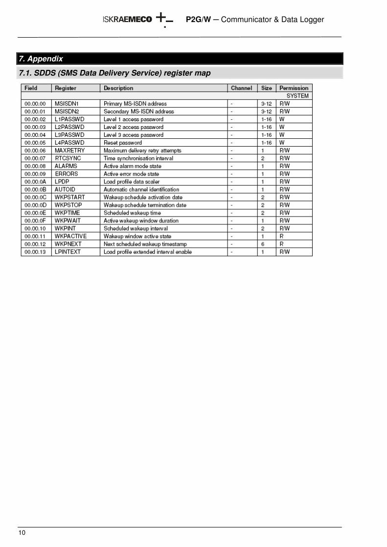
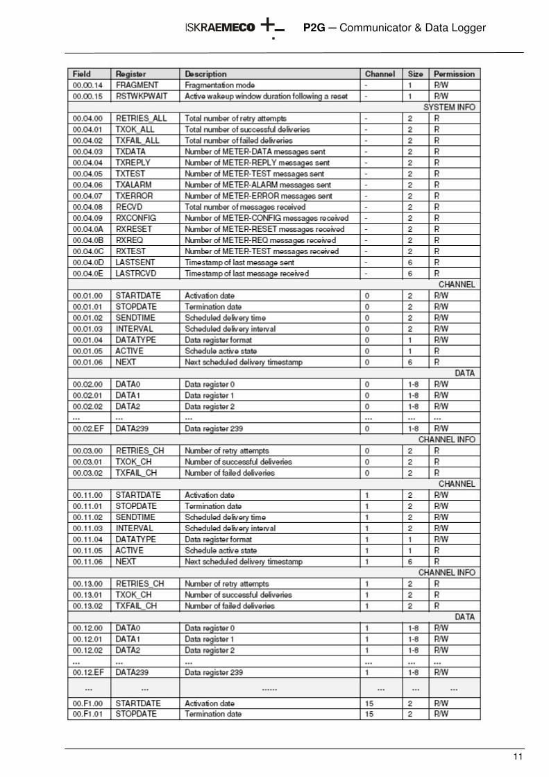
7. Appendix
7.1. SDDS (SMS Data Delivery Service) register map
11
P2G � Communicator & Data Logger
12
P2G � Communicator & Data Logger
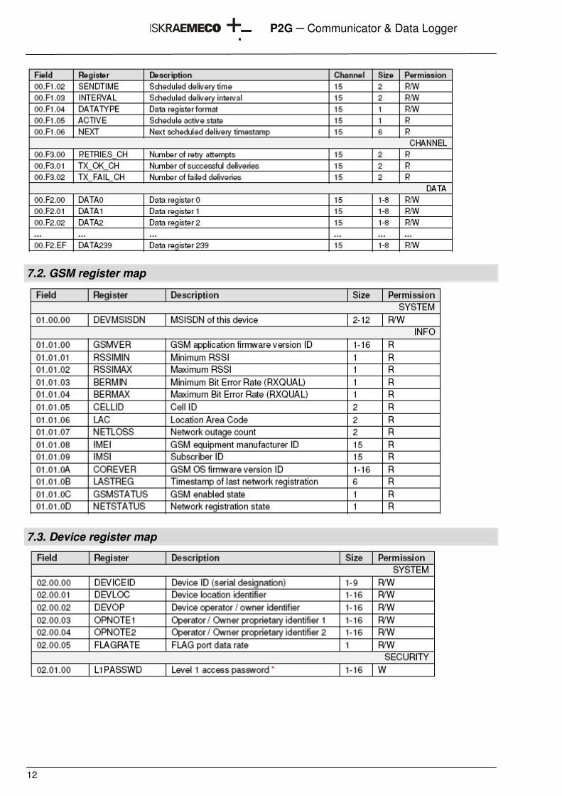
7.2. GSM register map
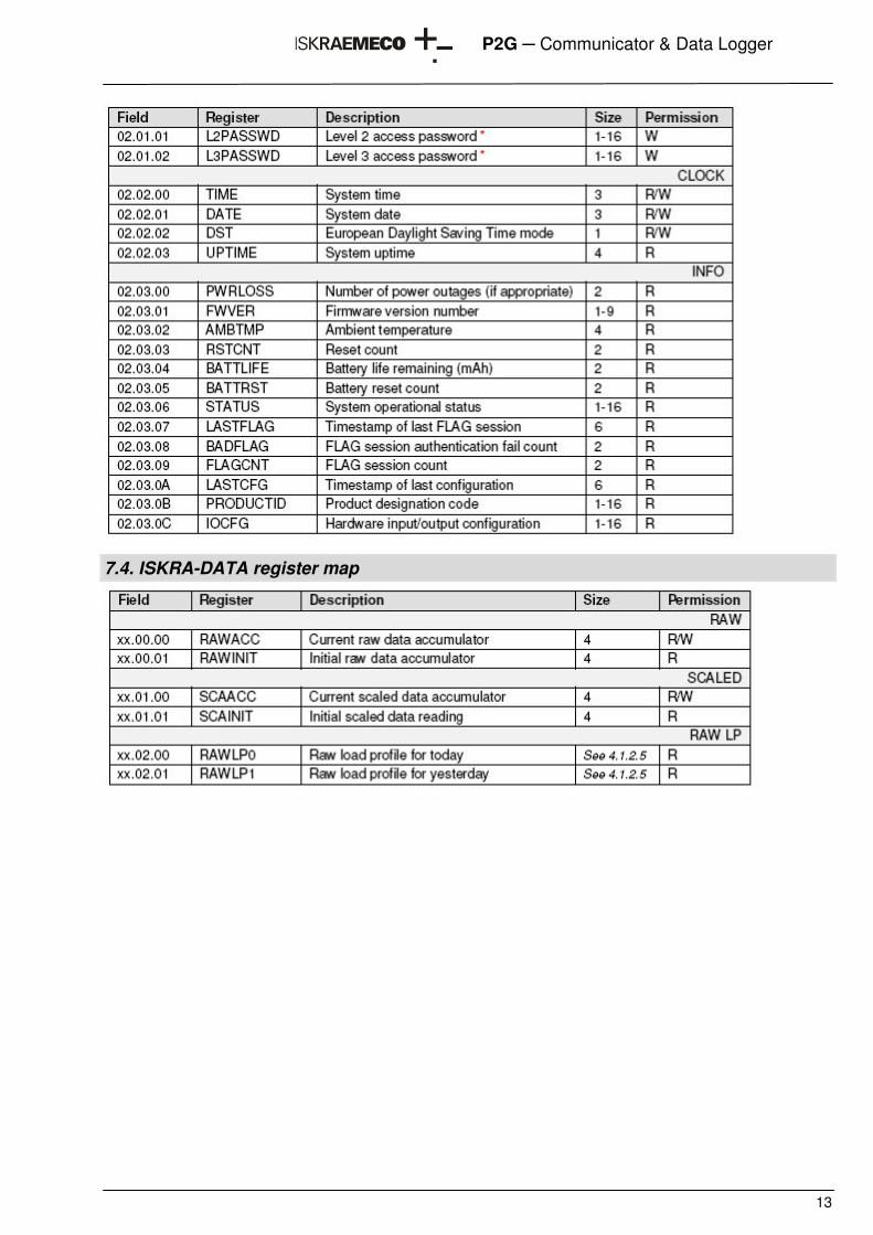
7.3. Device register map
13
P2G � Communicator & Data Logger
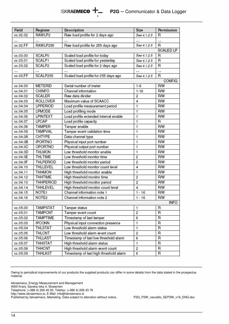
7.4. ISKRA-DATA register map
14
P2G � Communicator & Data Logger
Owing to periodical improvements of our products the supplied products can differ in some details from the data stated in the prospectus material.
Iskraemeco, Energy Measurement and Management 4000 Kranj, Savska loka 4, Slowenien Telephone: (+386 4) 206 40 00, Telefax: (+386 4) 206 43 76 http://www.iskraemeco.si, E-Mail: [email protected] Published by Iskraemeco, Marketing. Data subject to alteration without notice. P2G_P2W_navodilo_SEP2W_v19_ENG.doc