Embed Size (px)
Citation preview
P5: A Protocol for Scalable Anonymous Communication ∗
Rob Sherwood Bobby Bhattacharjee Aravind SrinivasanUniversity of Maryland, College Park, Maryland, USA
{capveg, bobby, srin}@cs.umd.edu
Abstract
We present a protocol for anonymous communication over the Internet. Our protocol, called P 5
(Peer-to-Peer Personal Privacy Protocol) provides sender-, receiver-, and sender-receiver anonymity. P 5
is designed to be implemented over the current Internet protocols, and does not require any specialinfrastructure support. A novel feature of P5 is that it allows individual participants to trade-off degree ofanonymity for communication efficiency, and hence can be used to scalably implement large anonymousgroups. We present a description of P5, an analysis of its anonymity and communication efficiency, andevaluate its performance using detailed packet-level simulations.Keywords: Anonymous Communication, Privacy, Peer-to-Peer
1 IntroductionWe present the Peer-to-Peer Personal Privacy Protocol (P 5) which can be used for scalable anonymouscommunication over the Internet. P5 provides sender-, receiver-, and sender-receiver anonymity, and canbe implemented over the current Internet protocols. P 5 can scale to provide anonymity for hundreds ofthousands of users all communicating simultaneously and anonymously.
A system provides receiver anonymity if and only if it is not possible to ascertain who the receiverof a particular message is (even though the receiver may be able to identify the sender). Analogously, asystem provides sender anonymity if and only if it is not possible for the receiver of a message to identifythe original sender. A property common to all anonymous systems is their inability to provide perfectanonymity. This is because it is usually possible to enumerate all senders or recipients of a particularmessage. In general, the degree of sender/receiver anonymity is measured by the size of the set of peoplewho could have sent/received a particular message. There have been a number of systems designed toprovide receiver anonymity [7, 11], and a number of systems that provide sender anonymity [22, 26]. Inthese systems, individual senders (or receivers) cannot determine the destination (or origin) of messagesbeyond a certain set of hosts in the network. Note that receiver anonymity is required by applications wherethe server needs to remain hidden, e.g., censorship resistant publishing, anonymous file distribution, or anypeer-to-peer application.
We assume that an adversary in our system may passively monitor every packet on every link of anetwork, and is able to correlate individual packets across links. Thus, the adversary can mount any passive
∗This work was supported by grants from the National Science Foundation (ANI0092806 and 0208005) and under ITR AwardCNS-0426683. This paper is an extended version of the original IEEE Security and Privacy 2002 conference paper. A list ofextensions is available in Appendix A.
1
attack on the underlying networking infrastructure. However, the adversary is not able to invert encryptionsor read encrypted messages. The adversary can also read all signaling messages in the system. A directimplication of this attack model is that the adversary can totally enumerate the network (e.g., IP) addresses ofthe members of the system. Further, assume that all members of the system have a digital pseudonym (e.g.,a public/private key pair), which by assumption, the adversary can also enumerate. The adversary, however,cannot map particular keys to specific addresses. Put another way, the crux of our (or any) anonymityprotocol is to conceal the mapping between digital pseudonyms and network addresses from the adversary.Last, assuming digital pseudonyms are implemented using public/private key pairs, we do not assume theexistence of a full PKI. Instead, we assume that if two parties wish to communicate, they are able to retrievethe public keys out of band ( this is discussed in more detail in Section 2.7).
The motivation for an attacker that can monitor arbitrary links comes from two observations. First, ifa protocol is secure against a strong adversary that can monitor arbitrary links, then it is secure against aweaker adversary than can only monitor a subset of links. For example, an attacker may compromise an ISPand monitor all incoming and outgoing traffic. In this case, any clients of the ISP are susceptible to exposure(and thus have no anonymity) unless the anonymous protocol defends against this model. Another weaker,yet more realistic, adversarial model is the trap and trace model. Under this model, the attacker subvertsthe internal auditing equipment of the telephone company or ISP(s) to follow specific links hop by hopiteratively back to the source (from the Wiretapping statues[3], this is known as trap and trace). In general, itis difficult to analyze a protocol’s security under a multitude of weaker passive attack models, so we assumea model that is a superset of all passive adversarial models. Second, we believe that this global passiveattack is indeed possible as evidenced by the Echelon[4, 24] and Carnivore[1] projects. While the exactdetails of Echelon are not public, the project’s apparent goal is to gather intelligence by monitor multiplediverse sources of information, including global Internet traffic, i.e., exactly the proposed adversarial model.Some sources[18] even claim that Echelon intercepts an estimated 90 percent of global Internet traffic,motivating the existence of a protocol such as P 5. Similarly, the FBI’s Carnivore system is installed ina number of ISPs across the country, and can be configured, by court order, to capture packets to a givenspecification. While the use of Echelon and Carnivore in the United States is strictly bound by constitutionalchecks and balances, these systems do provide constructive evidence for our attack model. In many partsof the world, the Internet is pervasive enough that it is not possible to completely shut it down; however,online communication is extensively monitored and even used as a basis for political persecution. In thesecountries, a system like P5 will likely prove useful for free exchange of ideas online.
Our system provides receiver and sender anonymity under this rather strong adversarial model, and addi-tionally provides the sender-receiver anonymity (or unlinkability) property. With sender-receiver anonymity,the adversary cannot determine if (or when) any two parties in the system are communicating. P 5 main-tains anonymity even if one party of a communication colludes with the adversary who can identify specificpackets sent to or received from the other end of the communication. Unlike previous known solutions, P 5
can be used to implement scalable wide-area systems with many thousand active participants, all of whommay communicate simultaneously.
1.1 A Naive SolutionConsider a global broadcast channel. All participants in the anonymous communication send fixed lengthpackets in to this broadcast channel at a fixed rate. These packets are encrypted such that only the recipientof the message may decrypt the packet, e.g., by using the receiver’s published public key. Assume that thereis a mechanism to hide, spoof, or re-write sender addresses, e.g., by implementing the broadcast channelusing an application layer peer-to-peer ring. Every message is hop-by-hop encrypted, and thus is it not
2
possible to map a specific incoming message to a particular outgoing message (in essence, each node actsas a mix[6]). It is possible that a node may not be actively communicating at a given time, but in order tomaintain the fixed communication rate, we require that the node send a packet anyway. Such a packet wouldbe a dummy or noise packet, and any packet destined for a particular receiver would be a signal packet.
This system provides sender anonymity, since all messages to a given receiver (in the case of a appli-cation layer peer-to-peer ring) come from a single upstream node, and the receiver cannot determine theoriginal sender of the message. This system also provides receiver anonymity because the sender does notknow where in the broadcast channel the receiver is or which host or address the receiver is using. Lastly,this solution provides sender-receiver anonymity from a passive adversary since the adversary is not able togain any information from monitoring any (or all) network links. Because all nodes send to the broadcastchannel at a fixed rate, all nodes send and receive at a fixed rate independent of who they are communi-cating with, or how many signal messages are sent/received. Note that the adversary is not able to tracea message from sender to receiver because of the hop-by-hop encryption, and thus even if one end of thecommunication is colluding with the adversary, the anonymity of the other party is not compromised.
This naive solution does not scale well due to its broadcast nature. As the number of people in thechannel increases, the available bandwidth for any useful communication decreases linearly, and the end-to-end reliability decreases exponentially. It is possible to increase the bandwidth utilization and reliabilityby limiting the number of users in a broadcast channel. One possible solution would be to create a set ofmultiple, independent channels, but then two parties who want to communicate may be unable to becausethey end up in different channels.
P5 is based upon this basic broadcast channel principle; we scale the system by creating a hierarchy ofbroadcast channels. Clearly, any broadcast-based system, including P 5 will not provide high bandwidthefficiency, both in terms of how many bits it takes a sender–receiver pair to exchange a bit of information,and how many extra bits the network carries to carry one bit of useful information. Instead, P 5 allows usersto choose how inefficient the communication is, and provides a scalable control structure for securely andanonymously connecting users in different logical broadcast groups. We present an overview of P 5 next.
1.2 Solution OverviewP5 scales the naive solution by creating a broadcast hierarchy. Different levels of the hierarchy providedifferent levels of anonymity, at the cost of communication bandwidth and reliability. Users of the systemlocally select a level of anonymity and communication efficiency and can locally map themselves to a levelwhich provides requisite performance. At any time, it is possible for individual users in P 5 to decreaseanonymity by choosing a more communication efficient channel. Unfortunately, it is not possible to regainstronger anonymity, as we will show in Section 3.4. Also, it is possible to choose a set of parameters thatis not supported by the system (e.g., mutually incompatible levels of bandwidth utilization and anonymity).The P5 system has been extensively modified from its original conference[25] version, and a summary ofthese modifications can be found in Appendix A.
1.3 RoadmapThe rest of this paper is structured as follows: we describe the P 5algorithm in Section 2 with specific detailsin Section 3, and present a set of analytic bounds on performance in Section 4. Section 5, we analyze resultsfrom packet-level P5 simulator. We discuss related work in Section 6. We discuss future work and concludein Section 7. Appendix [25] contains a summary of updates from the original conference paper.[25]
3
2 The P5 ProtocolP5 is based upon public-key cryptography. P5 does not require a global public-key infrastructure; however,we do assume that if two parties wish to communicate, they can ascertain each other’s public keys using anout-of-band mechanism.
Assume N individuals1 wish to form an anonymous communication system using P 5. Assume each ofthese P5 users have public keys K0, . . . KN−1. P5 will use these N public keys, called communicationkeys to create a logical broadcast hierarchy.
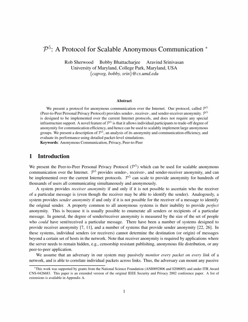
2.1 The P5 logical broadcast hierarchyThe P5 logical broadcast hierarchy is a binary tree (L) which is constructed using the public keysK0, . . . ,KN−1.Each node of L consists of a bit string of a specified length. We present the algorithm assuming each nodeof L contains both a bit string and a bit mask. The bit mask specifies how many of the most significant bitsin the bit string are valid. Though not strictly necessary, the addition of the bit mask will significantly easeour exposition. We use the notation (b /m) to represent a node, i.e., a user, in L where b is the bit string, andm is the number of matched bits.2
The root of L consists of the null bit string and a zero length mask. We represent the root with thelabel (? / 0). The left child of the root is the node (0 / 1) and the right child is (1 / 1). The rest of the treeis constructed as shown in Figure 1. For example, the node (0 / 1) represents the bit string 0 and the node(00 / 2) represents the bit string 00.
Each node in L corresponds to a single user of P5. Messages are (unreliably) forwarded to a subset ofall members of the system. That subset of members, called a broadcast channel, is denoted CH(b /m). Theset of nodes in a channel is defined as follows: user A, joined at node (b ′ /m′), is in channel CH(b /m) ifand only if the k most significant bits of b and b ′ are the same, where k is defined to be min{m,m′}. Wecall this common prefix testing the min-common-prefix check.
Thus, a message sent to a channel CH(b /m) is sent to three distinct regions of the L tree:
• Local: A message sent on CH(b /m) is sent to the (b /m) node.
• Path to root: For each m′ < m, this message is also broadcast to all nodes (bm′ /m′), where bm′
denotes the m′-bit prefix of b.
• Subtree: Lastly, for all m′′ > m, this message is also sent to all nodes (b|? /m′′), where b|? is any bitstring that begins with the string b.
Figures 2-5 show examples of broadcast channels.Note that these broadcast channels should be implemented as peer-to-peer unicast trees in the underlying
network (and not multi-cast trees). These channels may lose messages and require no particular consistency,reliability, or quality-of-service guarantees. We describe the precise networking and systems requirementsof P5 and underlying protocols in Section 3.5.
In general, communication efficiency increases as the channel’s size decreases, corresponding to thechannel’s mask size increasing. However, as we shall see, the anonymity of a node relates to the size ofthe channel which is communicates with, so this increase in efficiency comes at an expense of reducedanonymity. The depth of the L tree grows depending on the number of people in the system (N ).
1It is entirely possible that the N keys belong to n different individuals, such that n < N . We discuss this issue in Section 2.6.2This is similar to the notation used to name CIDR[13] address blocks
4
2.2 Mapping users to L
We use a secure public hash function (H(·)) to map users to L nodes. Consider user A, with public-key KA.Assume bA = H(KA). User A will join as a node in some channel of the form CH(bA /m). The length ofthe mask m, i.e., which channel, is chosen independently by user A according to a local security policy, asdescribed in Section 2.5. Given a chosen channel to join, the exact node that A has joined to in that channelshould be kept secret, and it should not be possible to determine which precise node a user is joined to.The node choice is only limited to the set of nodes that pass the min-common-prefix check with the chosenchannel. Thus, given a public key, it is public knowledge which set of nodes a user may be in, but it isdifficult to determine which specific node in this set the user has chosen. This is the key to the anonymity ofthe system.
We say a channel c is common between A and B if and only if messages sent to c are forwarded toboth A and B. Suppose A and B join channels CH(bA /mA) and CH(bB /mB) respectively, and assumeboth know each other’s public key, KA and KB , respectively. Since A knows KB , it can determine bB (bB=H(KB)); however, A does not know the value of mB . Even without any knowledge of the masks, Aand B can begin to communicate by broadcasting to the entire system, i.e., by using the CH(? / 0) channel.Unfortunately, this communication channel can be quite lossy since messages have a higher probability ofgetting lost in the channels “higher” up in the L tree and CH(? / 0) is the highest/most lossy communicationchannel of all. Also, if channels are chosen uniformly at random as a function of the public keys (as above),then there is approximately 50% probability that CH(? / 0) will be the only channel that A and B would havein common!
Our solution to this inefficient messaging is each user joins multiple channels on the logical tree. Foreach joined channel, users generate another public-private key pair, called routing key, which is kept distinctfrom its main public key: its communications key. These routing keys are generated locally, and do notrequire any global coordination. In fact, it should not be possible to map a user’s routing key to theircommunication key, otherwise, the user’s anonymity can be compromised (using an Intersection attack,Section 2.6).
When user A joins a channel c, it periodically sends a message to the channel listing other channelsthat it is joined to. These messages serve as a routing advertisement, and alert nodes about more efficientlateral routes along the lower levels of the L tree. In general, the advertisements from a node contains theset of channels it can directly reach, the set of channels it can reach using one other node, and so on. Ineffect, these t routing keys generate lateral edges in the tree. In Section 4, we show that typically, each userneeds to join only a few channels (≤ 3) for any two users in P 5 to have short paths (≤ 2 channel crossings)between them with high probability.
With each user joining multiple channels, the communication proceeds as follows. Instead of sendingmessages through CH(? / 0), A discovers multi-hop lateral routing paths from any of the channels it hasjoined to one of the set of channels specified by B’s communication key. By acquiring sufficient routingdiscovery messages, A then tries to send messages to some channel CH(bB /m). As above, while A cancalculate bB , the problem is it does not know which m B has chosen. In other words, A knows a set ofchannels that B may be in, i.e., CH(bB / 0), CH(bB / 1), CH(bB / 2), . . . , but not which specific one. LetA guess a value m, and send a message to CH(bB /m). If m ≤ mB , i.e., if the channel guessed is asuperset of B’s chosen channel, then B can respond with the correct mB , and communication can proceedmore efficiently. In this manner, A can probe for the correct channel that B has joined. However, if A hasguessed an m that is strictly smaller than mB , then B must ignore3 the message. Failure to do so results
3In practice this translates to not passing the message up to the application layer
5
in a difference attack (Section 2.6). Lastly, note that the communication efficiency is upper bounded by thelargest of the two channels chosen by either of the participants in a communication.
We note that a user joins a set of channels only when it enters the system, and should not change the setof channels it is part of. Otherwise, once again, yet another intersection attack becomes feasible that cancompromise their anonymity.
2.3 Signal and NoiseAssuming packet sources cannot be traced from the broadcast messages (See Section 3.1 for the precisepacket format), the protocol as described provides sender and receiver anonymity. We assume that eachmessages is of the same size and is encrypted per-hop, and thus it is not possible to map an outgoing message(packet) to a specific packet that the node received in the past. However, a passive observer can still mountan easy statistical attack and trace a communication by correlating a packet stream from a communicatingsource to a sink.
Thus, we add the notion of noise to the system. The noise packets should be added such that a passivecorrelation attack becomes infeasible. There are many possible good noise-generation algorithms, and weuse the following simple scheme.
Each P5 user, at all times, generates fixed amount of traffic destined to their advertised channel. Apacket transmitted from a node is one of the following:
• A packet (noise or signal) that was received from some incoming interface that this node is forwardingonto some other channel(s). (The precise forwarding rule for P 5 is described in Section 3.2).
• A signal packet that has been locally generated.
• A noise packet that has been locally generated.
Note that a critical property of this system is that to an external observer, there is no discernible dif-ference between these three scenarios. In general, only the source and destination of a communication candistinguish between noise and signal packets. They are treated with equal disdain at all other nodes.
Message Discard Algorithms In any communication system without explicit feedback, e.g. our channelbroadcasts, message queues may build at slow nodes or at nodes with high degree. In P 5, members maysimply drop any message they do not have the bandwidth or processing capacity to handle. The end-to-end properties of the system depend upon how messages are dropped. We have considered two differentdropping algorithms:
• Uniform drop: This is the simplest scheme in which messages from the input queue are dropped withequal probability until the input queue size is below the maximum threshold.
• Non-uniform drop: In this scheme, messages which are destined to larger channels, i.e., higher up inL are dropped preferentially.We have experimented with several variations of this scheme; the specific scheme which we use forour simulations drops packets destined for higher nodes with an exponentially higher probability.If most of the end-to-end paths in a P5 network can use lateral edges, i.e. between channels at thesame logical height, then this scheme provides lower drop rate. However any communication thatmust use “higher” channels have proportionately high drops.
6
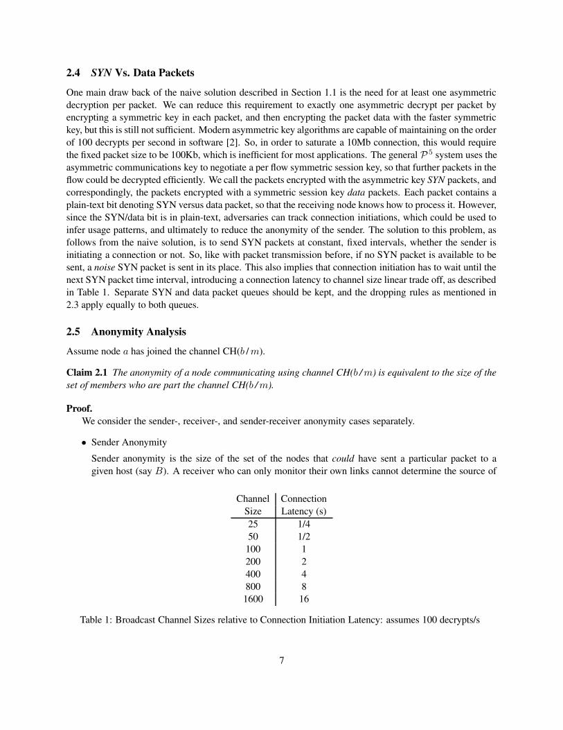
2.4 SYN Vs. Data PacketsOne main draw back of the naive solution described in Section 1.1 is the need for at least one asymmetricdecryption per packet. We can reduce this requirement to exactly one asymmetric decrypt per packet byencrypting a symmetric key in each packet, and then encrypting the packet data with the faster symmetrickey, but this is still not sufficient. Modern asymmetric key algorithms are capable of maintaining on the orderof 100 decrypts per second in software [2]. So, in order to saturate a 10Mb connection, this would requirethe fixed packet size to be 100Kb, which is inefficient for most applications. The general P 5 system uses theasymmetric communications key to negotiate a per flow symmetric session key, so that further packets in theflow could be decrypted efficiently. We call the packets encrypted with the asymmetric key SYN packets, andcorrespondingly, the packets encrypted with a symmetric session key data packets. Each packet contains aplain-text bit denoting SYN versus data packet, so that the receiving node knows how to process it. However,since the SYN/data bit is in plain-text, adversaries can track connection initiations, which could be used toinfer usage patterns, and ultimately to reduce the anonymity of the sender. The solution to this problem, asfollows from the naive solution, is to send SYN packets at constant, fixed intervals, whether the sender isinitiating a connection or not. So, like with packet transmission before, if no SYN packet is available to besent, a noise SYN packet is sent in its place. This also implies that connection initiation has to wait until thenext SYN packet time interval, introducing a connection latency to channel size linear trade off, as describedin Table 1. Separate SYN and data packet queues should be kept, and the dropping rules as mentioned in2.3 apply equally to both queues.
2.5 Anonymity AnalysisAssume node a has joined the channel CH(b /m).
Claim 2.1 The anonymity of a node communicating using channel CH(b /m) is equivalent to the size of theset of members who are part the channel CH(b /m).
Proof.We consider the sender-, receiver-, and sender-receiver anonymity cases separately.
• Sender AnonymitySender anonymity is the size of the set of the nodes that could have sent a particular packet to agiven host (say B). A receiver who can only monitor their own links cannot determine the source of
Channel ConnectionSize Latency (s)25 1/450 1/2
100 1200 2400 4800 81600 16
Table 1: Broadcast Channel Sizes relative to Connection Initiation Latency: assumes 100 decrypts/s
7
a packet since this information is never included in the packet. A receiver, in collusion with a all-powerful passive adversary, however, can enumerate the set of nodes who could have sent the packetby computing the transitive closure of the set of nodes who have a causal relationship with B. (In thiscase, nodes X and Y are causally related if X sent a packet to Y ). This closure would be computedover some finite time window on the order of the end-to-end latency in the system.However, in P5 , a user connected to CH(b /m) sends packets at a constant rate (signal or noise), andthese packets are received by all users in CH(b /m). Thus, there is a causal relationship between everyuser in a broadcast channel. Additionally, via lateral paths, nodes transmit packets between channels,and over time every node in the system is causally related to every other node in the system.Suppose a malicious receiver tries to expose a sender that it is communicating with. Assume thecommunication stream is one way from the sender to the receiver. Given our assumption that thesource IP address is obscured by the hop-by-hop retransmission, and that the packet contains noreturn addressing information, the malicious receiver is not able to distinguish the sender from anynode in the system. It cannot even assert that a given set of nodes are not the sender.
• Receiver AnonymityWhen A sends a packet to B at channel CH((bB /mB), every member of CH(bB /mB) receives thepacket. From the perspective of an external observer, the behavior of the system is exactly the samewhether B receives the packet or not. Thus, B is indistinguishable from any other node in the samebroadcast channel. Thus, B’s anonymity is exactly equivalent to the set of all users who receive thepacket, namely the channel CH(bB /mB).
• Sender-receiver anonymitySince all nodes in the system send at a constant rate, and all packets are pair-wise encrypted betweeneach hop, we claim that it is impossible for a passive observer to distinguish noise from signal packets.Since the observer cannot distinguish signal packets, it cannot discern if or when A communicates,and thus, it cannot determine when A is communicating with any other node B.
2
Assume that the rate at which some user A sends packets does not change when it is sending signalversus noise packets. In this case, the distribution of packets, whether they are signal packets or noise, doesnot affect the security of the node. Thus, a nice property of our system is that the anonymity of any node Adepends only upon the length of the mask that A is willing to respond to, not the rate at which it transmits.
2.6 AttacksIn this section, we outline a number of attacks common to all anonymity systems,and show why P 5 resiststhem.
• Correlation Attack:As we have already alluded, a passive observer who is able to detect when signal packets are sent fromthe sender, and received by the receiver (independent of the content) is able to statistically correlatethese events over time to discern that the two parties are communicating. If this adversary colludeswith the sender, who knows the pseudonym of the receiver, it is possible to map the node’s address tothe pseudonym, breaking the anonymity. In P5 this attack is thwarted because the adversary cannotdiscern signal packets from noise.
8
• Intersection Attack: If an adversary knows that a user is two different sets U and V , then theanonymity of the user is reduced to U ∩ V . If users are uniformly distributed across such setsthat can be intersected, then the anonymity for any user in these reduces exponentially with the num-ber of intersecting sets. For example, suppose users communicate using both their routing keys andtheir communication key. With each key, there is a corresponding set of users who may own that key.This leads to an intersection attack. This is the reason a user communicates with only one key in P 5,and routing keys cannot be mapped back to the communication keys. Note that this is also the reasonusers cannot increase their anonymity beyond the smallest set they have ever been mapped to.
• Difference Attack: If an adversary can map the user to some set U and can assert that the user is notin some other set V , then it can map the user to the difference between these two sets, U − V .For example, suppose user A has joined CH(b /m). In this case, it should ignore packets sent to anychannel CH(b /m′) where m′ > m. If A does respond/react/acknowledge such packets, then A isdivulging where in the L it is not. That is because the receiver set of CH(b /m ′) is smaller than thereceiver set CH(b /m), and now an adversary knows that A is not in the difference between the twochannels.
• DoS flooding attack: Suppose a malicious user wants to reduce the efficiency of the system bysending a large number of useless packets. P5 can withstand this type of an attack since we imposea per-link queue limit, and all the extra packets from the malicious user will be dropped at the veryfirst hop. Note that even the local broadcast channel is not affected by a DoS attack as long as the firstnon-colluding hop correctly implements its queue limits.
• Forwarding DoS attack: In P5 a selfish node may chose drop traffic that is not its own. If thesource and destination of the traffic are in different channels, one potential method to mitigate thisattack is to re-route traffic through another, potentially longer, path. While section 4 provides boundson the minimum length of the path between two channels, there are multiple paths between any twochannels. In the case where the source and the destination of the traffic are in the same channel, itis still possible to re-route the traffic around a malicious node by forwarding the traffic to anotherchannel, and then back to the destination channel at a different point.
• Drop Rate Partitioning: Assume that an attacker is in an extended conversation with the victim, longenough to measure the average rate at which packets are dropped. Further assume that the attacker iscolluding with a number of other hosts in the system, and can obtain average drop rate informationfor these hosts, as well as their distances in hop counts. In the case of the naive solution with thebroadcast ring, two attackers, A1 and A2, can use this method to reduce the anonymity of the victim,V , as follows. Since there is a single path through the system, showing that A1 has a lower drop ratewhen talking to V than it does when talking to A2 implies that V is between A1 and A2, otherwise Vis not between them. In either case, some amount of of anonymity is lost: this is a difference attack,as defined above.However, this attack breaks down in the general P 5 case because there is not a single path throughthe system, and it is difficult to make assertions about the path from Ai to V relative to the path fromAi to Aj . For example, assume that A1 is communicating with V , and with A2, and has measuredtheir respective drop rates, as above. Because there are in general many multi-hop lateral paths inthe system between any two channel, and the sender can change between paths without notifying thereceiver, it is not possible to make assertions about path characteristics over time.
9
2.7 Obtaining Public Keys Out of BandP5 assumes that if Alice wishes to communicate with Bob, that she can obtain Bob’s public key out ofband from the system. However, Alice must be careful how she does this, as the act of fetching the key, forexample querying a public server for Bob’s key, could potentially break the anonymity of the communicationbefore even using P5. One possibility is Alice could obtain the key from a trusted party. This is not as uselessa technique as it would appear at first pass, because Alice needs someone to tell her about the existence ofBob, and to give Alice some reason for wanting to contact him. Another possible solution is a globaldirectory service which publishes public keys, like a phone book. The downfall of this solution is that Alicehas to keep state for all public keys in the entire system. A much more elegant solution, however, is to runa public key server as a service in the P5 system itself. The public key for the server could be well knownin the system, and any communications to the server would be, by definition, as anonymous as any othercommunication in P5.
3 DetailsWe have implemented P5 in a packet level simulator, but the details from our simulation would be useful ina “real” implementation as well.
3.1 Packet FormatWe use fixed length packets of size 1 KB. The fixed packet length is used to eliminate any informationan adversary can gain by monitoring packet lengths. The 1 KB size was chosen arbitrarily as a trade offbetween packet fragmentation and communications efficiency, and is not integral to the system.
The P5 header only contains the identifier for the first hop destination channel (a (b/m) pair), and a flagdenoting a SYN versus data packet, as described in Section 2.4. In our simulation, b is a 32 bit unsignedinteger, and m is a 6 bit integer. Since packets may need to be encapsulated, and each packet is the samesize, each packet also contains a padding field which is the size of the P 5 header.
The payload of a P5 SYN packet contains a set of fixed size “chunks”, each of which is encrypted withthe receiver’s public key. These chunks are formed naturally by many public-key encryptions. The decrypteddata part of the P5 packet contains a checksum which the receiver uses to determine whether a packet isdestined for itself or not. Each chunk can be decrypted independently; thus, a receiver does not need todecrypt an entire noise packet, it can discard a packet as soon as the first chunk fails its checksum. Forefficiency, the first chunk of a signal packet may also include a symmetric cipher key for use in decryptingthe other chunks, as symmetric cipher decryptions tend to be faster than asymmetric ones.
Regardless of whether a packet decrypts properly, the receiver schedules each packet for further deliverywithin the local channel using the forwarding rule described below.
The first chunk of a signal packet contains an encrypted bit which determines whether a packet should beforwarded onto some other channel, or whether the packet is destined for the current node. It also containsa channel identifier for the ultimate destination for the packet, which the current node uses to choose anoutgoing channel.
When a node receives a packet with the “forward” bit set, it interprets the rest of the data as anotherP5 packet, and if possible, forwards it onto the specified channel. In the forwarding step, the process at achannel router is different depending on whether the packet is at its ultimate channel or not:
10
• If the packet is not at its final channel, the current node replaces the first chunk with a new chunk inwhich the “forward” bit is set, sets the proper ultimate destination channel, and encrypts this chunkwith the public key of the next hop.If the packet is already is the destination channel, then the data part of the packet is already formattedwith the proper address and has a valid first chunk encrypted by the public key of the intended recipi-ent. The current node adds a last chunk at end of the packet with random bits to increment the packetlength to the fixed system size.
If the “forward” bit is not set, then this signal packet is delivered to the local channel.
3.2 Forwarding within a channelSince each broadcast channel is a tree, each node can use the following simple forwarding algorithm toforward a packet p along CH(b /m):
Forward p to a node A if and only if only if p did not come in on A and if A passes the min-common-prefix check with respect to CH(b /m).
Note that it is important that the output order of the packets not be determined by the input order, elseit becomes possible to correlate packets across successive nodes and trace communication between twoparties. In other words, a mix [6].
3.3 Channel Selection and Join AlgorithmsAnalogous to the definition in [22], we define anonymity for a user A as the set S of users who are in-distinguishable from that A, i.e., no other user or a passive adversary can resolve messages from A to agranularity finer than S. From Section 2.5, we know that in P 5 the set S is equivalent to the size of thechannel A joined. In this Section, we discuss how A selects a channel, and how to actually join.
We assume that each user u requires a minimal acceptable level of anonymity, i.e. each user requirestheir corresponding S set to be of a minimum size. We call this minimum set size the security parameter,and denote it with ψu. Each user u may also define a maximum required level of security (i.e. a maximumsize of the corresponding S set) since this provides a bound on the communication inefficiency. We call thisthe efficiency parameter, and denote it with ηu. Thus, a node wants to find a channel that is “large enough”to fit their security parameter, but “small enough” to still be efficient. In other words, user A chooses achannel CH(b /m), such that ψA ≤ |CH(b /m)| ≤ ηA with the following algorithm:
• A initially picks channel CH(? / 0). If ψA ≤ |CH(? / 0)| ≤ ηA, then both security and efficiencyrequirements are met, and the node is done.If ψA > |CH(? / 0))|, A the entire system does not have enough members to provide the requisiteanonymity. Thus, A forwards packets for other nodes and sends noise packets, but does not directlycommunicate with other nodes until such time as more nodes have joined the system to meet thesecurity requirements.
• If |CH(? / 0)| > ηA, then this channel has too many nodes, and A picks the appropriate channel of theform CH(b / 1), i.e., one level lower on the tree. A repeats this procedure by incrementing m until itfinds a CH(b /m) such that ψA ≤ |CH(b /m)| ≤ ηA.
11
Once the user has picked the appropriate broadcast channel CH(b /m) to join, they must physicallyjoin the tree to start receiving messages. The difference between the joined node and the joined channel issubtle but important. Joining channel CH(b /m) means that the user is one of the nodes (b ′ /n′) that receivesbroadcast messages sent to that channel. Specifically, this implies that (b ′ /n′) and CH(b /m) pass the min-common-prefix check. It should not be possible to discover a the specific node a user has joined at, only thechannel they have chosen.
Given that the user decides to join channel CH(b /m) where b = b0 . . . bm−1, they pick which node tophysically join using the following rules:
• Starting at the root node (?/0), i.e. at the i = 0th level of L traverse down the tree following the leftchild if bi = 0, or the right child if bi = 1, i.e. a binary search.
• Once the node corresponding to (b/m) has been found, continue descending down the tree, pickingthe left or right child uniformly at random, until the bottom of the tree is reached.
• Physically join by connecting as a leaf to the last node visited.
More generally, a new user joins as a random leaf in the subtree rooted at (b /m), as shown in figures6-8.
Clearly, it is possible to choose incompatible values ψ and η such that η > |CH(b /m)| and ψ >|CH(b /m + 1)|. In this case, the user can either change their security or efficiency parameter or wait inchannel CH(b /m+ 1), until ψ ≤ |CH(b /m+ 1)|.
In our simulations, each user can determine the number of people in a channel by consulting an oraclewhich maintains an up to date list of channel memberships. In implementation, this information can bemaintained in a secure distributed manner, either by the underlying application-layer multi-cast primitive,or at a well-known centralized topology server.
The topology server construct is needed if it is not possible to infer approximate channel sizes. Thetopology server keeps pairs of the form 〈CH(b /m) : IP address〉, where CH(b /m) is the communicationchannel of the node. It is possible for the topology server to expose a user by providing false information(reporting a channel is large when it is in fact not). For extra security, the topology information can bereplicated at l different topology servers. A user would only consider the minimum channel size reportedby all topology servers; this way, a user can withstand up to l − 1 colluding malicious topology servers.Similar techniques can be used to handle malicious topology servers who return a value smaller than theactual channel size (to make the communication inefficient). Also, note that the topology servers can also beused to find users on a specified channel, which is needed when a new user joins a channel. Further note thata node can keep track of the depth of the tree when it physically joins. Assuming that the tree is balancedbecause nodes join as random leaves, then the size of the channel can be estimated from the depth of thetree. This estimate provides an additional “sanity check” on the results returned by the topology server.
3.3.1 An Example of P5 Communication
Consider the following example: Alice has KA such that H(KA) = 0000 . . .. Alice has locally determinedthat ψA = 8 and ηA = 10, so Alice wants to find a channel to join that is larger than 8 but smaller than 10.Assume the logical tree L looks like Figure 9 before she attempts to join. Node Alice can choose to anychannel that passes the min-common prefix test with H(KA), specifically: CH(? / 0) (28 nodes), CH(0 / 1)(14 nodes), CH(00 / 2) (8 nodes), CH(000 / 3) (5 nodes), and CH(0000 / 4) (5 nodes). Alice chooses to joinCH(00 / 2), because it is the only channel that fits both her security and efficiency parameters (Section 3.3).
12
To join CH(00 / 2), Alice joins as a random leaf of the tree rooted at node (00 / 2), specifically, Alice becomesnode (0001 / 4). Additionally, Alice joins two other channels (Figure 10), CH(01 / 2) as node (0101 / 4) andCH(11 / 2) as node (1001 / 4), chosen uniformly at random to create lateral links across the tree. Alicegenerates random routing keys, R1, R2, and R3, for each channel joined, and starts broadcasting routingavailability messages, e.g., “Channel CH(00 / 2) is reachable from CH(01 / 2) using key R2”. Also, Alicestarts to cache other node’s routing availability messages in a local routing table.
Next, Alice decides she wants to talk to Bob, but she does not know what channel he is in. Assumingthat Alice obtains Bob’s private key, KB , out of band (Section 2.7), she now knows which set of channelsBob must be in, but not which specific one. Using, the channel CH(? / 0), i.e., the entire system, Alice sendsa message to Bob to find out which specific channel he is in. Note that Alice is a member of CH(? / 0), so shecan send the message directly, as opposed to routing through an intermediary channel. Since the channelis quite lossy, Alice needs to resend the message a number of times, but eventually gets a response fromBob that he is in CH(11 / 2). This implies that Bob is one of the nodes that passes the min-common-prefixcheck with CH(11 / 2), but Alice does not know which specific node, leaving Bob anonymous to the size ofCH(11 / 2). However, Alice is not a member of CH(11 / 2), so she is forced to route the message througha third party. After consulting her local cache of routing advertisements, Alice discovers that there existsa node C that routes from CH(10 / 2), which Alice is a member, to CH(11 / 2), where Bob is. As shownin Figure 11, Alice then broadcasts the message out on CH(10 / 2) to C’s routing key. Node C reads themessage, decrypts it, then rebroadcasts the message on CH(11 / 2) (Figure 12), where Bob receives it.
Note that despite the fact that Alice and Bob have both joined CH(10 / 2), they cannot communicate onthat channel, or even know that they have both joined the same channel! Recall that both joined the channelto create lateral links across the tree, not to communicate. If, for example, Bob told Alice that he was also inCH(10 / 2), then Alice could intersect the set membership of channels CH(10 / 2) and CH(11 / 2), and reduceBob’s anonymity. In other words, Alice could mount an intersection attack on Bob.
3.4 Handling Node ChurnSupposeA is in channel CH(b /m), and theA’s security and efficiency parameters are met, i.e., ψA ≤ |CH(b /m)| ≤ ηA.As users join and leave the system, it is possible for the channel CH(b /m) to violate A’s security or effi-ciency parameter. If too many nodes join A’s channel and its efficiency parameter is violated, A can migrateto channel CH(b /m+ 1), as long as the security requirement is maintained.
In contrast, if too many nodes leave the system, A’s security parameter can be violated. For example,suppose A with ψA = 75 and ηA = 150, joins a channel that contains 100 users. But, over time due to nodeleaves and failures, 40 nodes leave and the size of the channel is reduced to 60. As noted by Wright[28],this is an inherent problem in all known anonymity systems. A key property of P 5 is that when a singlenode leaves, a channel’s anonymity is diminished by exactly one. In other words, in the example above, A’ssecurity parameter is violated only once 25 nodes leave A’s channel.
When a node’s security parameter is violated, unfortunately A cannot re-gain any security by migrating“up” L (i.e. by decreasing m). This is because an intersection attack fixes SA to the size of the smallestchannel that A was part of since it initially joined. Thus, A’s only available action is to leave the system,and rejoin under a different key.
We mitigate this costly operation as follows. Assume that the joining node has some knowledge of theaverage rate over time that nodes leave the system, α. The value α could be inferred from querying thetopology servers over time, or maintained by the topology servers themselves. Given α, the newly joiningnode A picks a k such that the time k
αis sufficiently long for A to finish all transactions in the system, or
long enough to amortize the cost of leaving the system and rejoining with a new key. Then, if ψ ′a is A’s
13
actual security requirement, A joins with an effective security parameter of ψa = ψ′a + k. In other words, A
picks a channel to withstand up to k node leaves before being forced to rejoin the system with a new key.Also, note that users who do leave the system open themselves to an intersection attack. An adversary
can enumerate all nodes that have left the system, by our passive monitoring assumption, and assuming itcan assert that a victim node has left the system (i.e., because the node is no longer responding to messages),can intersect that set with a victim’s last known channel. Thus, there is incentive for nodes to persist in thesystem. This attack is not unique to P5 and is common to all systems with similar adversarial models.
3.5 The Network Abstraction and Processing RequirementsIn this section we describe the precise networking requirements of P 5. It was our design goal for P5 to beeasily implementable using the current Internet protocols, as such our networking requirements are meager.
P5 requires the implementation of broadcast channels in which the source address cannot easily bedetermined. This can be efficiently implemented using a application-layer multi-cast protocol. The transportlevel requirements of P5 are minimal, and UDP would suffice as the transport protocol for P 5 edges on theunderlying physical topology. Lastly, note that during normal operation, P 5 members only remain joined tothe same set of channels; they only change channels if the overall security policy changes or if the channeldynamic changes drastically. Thus, the signaling load due to P 5 is low, and since the topologies within eachchannel is relatively static, the P5 tree can be optimized to map efficiently on to the underlying physicaltopology.
Host Requirements P5 requires state, processing, and link bandwidth at each host. We discuss theserequirements in turn:
• Suppose memberA communicates using channel CH(b /m) at depth m in L. In order to communicatewithin the channel, A may have to maintain next hop information about 2m channels. For small m(e.g. m < 16), the state requirements are minimal. Note that unlike an IP router, A does not haveto search its “routing table” for every packet; it only searches this table when it initiates a new dataconnection. Thus, this table can be maintained in secondary storage.Ifm is large (e.g. m ≥ 24), it may not be feasible for a node to maintain information about all 2m peerchannels. In this case, A could maintain a small cache of advertisements, and if a new communicationrequires a channel that is not in the cache, A would have to wait until it hears another advertisementfor that channel.
• There is a single public-key decryption for every connection initiation, or SYN packet, that memberA receives . Further, A is required to encrypt every signal packet during communication. However, ingeneral, A does not have to encrypt noise packets; it is only necessary that the adversary not be ableto distinguish noise packets from signal packets. Thus, it is feasible for A to generate noise packetsusing a good local random number source.
• The broadcast nature of P5 requires individual channel members to (potentially) devote more band-width for communication than pure unicast (or systems such as Crowds [22]). However, the extrabandwidth directly results in enhanced anonymity, and, obviously, individual users may choose amore bandwidth efficient channel if they are willing to sacrifice some anonymity. We analyze theactual bandwidth usage and how it scales with number of channel members and different securityparameters in Section 5.
14
3.6 P5 Nodes as IP ProxiesAs described above, if two nodes want to communicate, they are required both to be members of the P 5
system. However, orthogonal to the actual protocol, it is possible to communicate with parties outside of P 5
if nodes implement IP proxies. Similar to existing anonymous communication systems[14, 22, 26], if nodeA wants to anonymously communicate with B that is not in the P 5 system, A can contact an arbitrary nodeC anonymously through P5, and C can in turn contact B, acting as an IP layer proxy for A to B. Note thatin doing so, B has no receiver anonymity because A must know B’s IP address to initiate the session. Also,the sender-receiver anonymity of A to B is lost, because C knows that someone is talking to B. However,the sender anonymity of A is still preserved.
It is worth noting that any anonymous protocol that allows traffic to leave the system must be designedwith care. Specifically, a naive implementation of IP proxies could lead to a trivial DoS attack. An attackersimply uses one or many proxies to flood a victim and remains anonymous in the process. Rate limiting andprotocol verification are two techniques that could be used to mitigate this attack.
4 The Random Channels ModelIn this section, we present an analysis of the paths in a P 5 network. Let n be the number of users in thesystem, and suppose there are k channels available in total. For some integer t (which is typically small—atmost 5), each user u independently chooses t random channels without replacement: we will denote thisrandom set of t channels by S(u). Two central parameters for us will be: (i) d, the maximum “hop-count”between any 2 users, which is the maximum communication distance between any two users, and (ii) Lmin
and Lmax, the minimum and maximum load (number of users) on any channel. Note that Lmin and Lmax
are different than the security parameters as they count only the set of users local to a channel, while thesecurity parameters count the set of users in all channels that provide anonymity for a given user. We nextdiscuss these two parameters.The parameter d. We say that there is a path u = u0, u1, u2, . . . , u` = v between two users u and v, if foreach i, users ui and ui+1 choose a channel in common. The length of such a path is defined to be `, and theminimum length of any path between u and v is the distance or hop-count between u and v; if there is nosuch path, then this hop-count is defined to be ∞. We are interested in bounding d, the maximum hop-countbetween any two users.The load parameters Lmin and Lmax. Define the load on a channel to be the number of users who choseit among their t random channels; let Lmin and Lmax respectively be the minimum and maximum loads onany channel. A lower bound on the former is needed to guarantee the security of the system, and an upperbound on the latter is required to show that the bandwidth overhead is not significant.
Given the above discussion, our basic goals will be as follows. Clearly, we simultaneously want “small”d, a value of Lmin that is “not too small”, and Lmax being “not too high”. It is easy to see that the expectedload on any given channel is exactly t · n/k. Thus, n/k is a natural parameter to study our system with. So,we will consider scenarios where k is constrained to be at most some given value K , and n/k is requiredto be at least some given value λ. So, the primary parameters are K , t, and λ. Given these, and for anychoice of (n, k) for which k ≤ K and n/k ≥ λ, we aim to show that the system has the above-sketchedsatisfactory properties w.r.t. d, Lmin, and Lmax.
More concretely, we will proceed as follows. Fix ε = 0.3, say. Let As denote the desirable event that“(i) all the channel loads are within 1 ± ε of the expected value tλ, and (ii) d ≤ s”. We derive the followingsufficient conditions for As to hold (for s = 2, 3) with a probability of at least 1 − 10−4:
15
1. s = 2: two sufficient conditions are
(P1) t = 3, λ ≥ 100, and K ≤ 100; or(P2) t = 4, λ ≥ 80, and K ≤ 300.
2. s = 3: two sufficient conditions are
(P3) t = 3, λ ≥ 100, and K ≤ 150; or(P4) t = 4, λ ≥ 80, and K ≤ 700.
We now prove that these conditions are indeed sufficient, in the rest of this section.
4.1 Analysis ApproachIn our analysis, we will frequently use the union bound or Boole’s inequality: Pr[E1 ∨ E2 ∨ . . . ∨ Es] ≤∑s
i=1 Pr[Ei].The parameters Lmin and Lmax are much more tractable than d, so we handle them first. Let exp(x)
denote ex. It is an easy consequence of large-deviations bounds such as the Chernoff-Hoeffding bounds[8, 15] that for any given channel c and any parameter ε ∈ [0, 1], its load L(c) satisfies:
Pr[L(c) 6∈ [(1 − ε) · tn/k, (1 + ε) · tn/k]]
≤ exp(−tε2/2 · (n/k)) +
exp(−t(ε2/2 − ε3/6) · (n/k))
≤ exp(−tλε2/2) + exp(−tλ(ε2/2 − ε3/6)).
Now, a simple application of the union bound yields
Pr[(Lmin < (1 − ε) · tn/k)∨
(Lmax > (1 + ε) · tn/k)]
≤ K · exp(−tλε2
2) +K · exp(−tλ(
ε2
2−ε3
6))] (1)
We next turn to bounding d. We cannot directly draw on the rich random graphs literature, since weare working here with a certain model of random hyper graphs with possibly repeated hyperedges. We nextstudy the two requirements of most interest: d ≤ 2 and d ≤ 3. As can be expected, the second case involvesmore work than the first. Our basic plan is as follows. Lemma 4.1 gives an upper-bound on Pr[d > 2],and Lemma 4.2 gives an upper-bound on Pr[d > 3]. Then, letting E denote the complement of event E , wesee by the union bound that Pr[A2] is upper-bounded by the sum of (1) and the probability bound given byLemma 4.1. Similarly, Pr[A3] is upper-bounded by the sum of (1) and the bound given by Lemma 4.2. Weshall do this “putting together” in Section 4.4.
4.2 The Requirement d ≤ 2
Here, we want sufficient conditions for “d ≤ 2” to hold with high probability. In other words, we want toshow that for any two users, there is a path of length at most 2 between them. To do so, we fix distinct usersu and v, and upper-bound the probability p that there is no path of length 2 between them; then, by the union
16
bound, the probability of d > 2 is at most(n2
)
· p, since there are only(n2
)
choices for the unordered pair(u, v). Thus, we need to show that p is negligible in comparison with (
(n2
)
)−1, which we proceed to do now.Our plan is to condition on the values of S(u) and S(v). For each such choice, we will upper-bound
the probability that there is no user (among the remaining (n − 2)) who chose a channel that intersectsboth S(u) and S(v). Then, the maximum such probability is an upper-bound on p. Fix S(u) and S(v). IfS(u)∩S(v) 6= ∅, then u and v are at distance 1; so suppose S(u)∩S(v) = ∅. In particular, we may assumethat k ≥ 2t.
Consider any other user w. What is the probability of w’s random choice S(w) intersecting S(u) andS(v)? The total number of possible choices for w is
(kt
)
. The number of possible intersection patterns canbe counted as follows. Suppose |S(w) ∩ S(u)| = i and |S(w) ∩ S(v)| = j, where i, j ≥ 1 and i + j ≤ t.The remaining t− (i+ j) elements of S(w) are selected at random from outside S(u) ∪ S(v). Thus,
Pr[(S(w) ∩ S(u) = ∅)∨
(S(w) ∩ S(v) = ∅)] = 1 − f(k, t),
where
f(k, t) =
∑
i,j≥1; i+j≤t
(ti
)(tj
)( k−2tt−i−j
)
(kt
).
Thus, since different users w make their random choices independently, we get that p ≤ (1− f(k, t))n−2 ≤exp(−(n− 2)f(k, t)). Thus, as discussed above, a union bound yields
Pr[d > 2] ≤ (n2/2) · exp(−(n− 2)f(k, t)). (2)
In order to see what this bound says for various concrete values of our parameters K,λ, t, we develop:
Lemma 4.1 Suppose λ ≥ 2K/(t3(t−1)) and K ≥ 2t+2. Then, Pr[d > 2] ≤ ((Keλ)2/2) ·exp(−0.8t3(t−1)λ/K).
Proof. (Sketch.) Since f(k, t) ≥ t2(k−2t
t−2
)
/(k
t
)
, bound (2) shows that
Pr[d > 2] ≤ (n2e2/2) · exp
(
−nt2(
k − 2t
t− 2
)
/
(
k
t
))
.
We can now do a calculation to show that subject to our constraints (which includes the constraint thatk ≥ 2t), this bound is maximized when k = K and n = λK . Further simplification then leads to the boundof the lemma.
2
4.3 The Requirement d ≤ 3
We now adopt a different approach to get an upper-bound on Pr[d > 4]. Let C denote our set of k channels.For a set A ⊆ C with |A| = t, define Y (A) to be the set of all a ∈ (C −A) for which the following holds:
∃x : (a ∈ S(x))∧
(S(x) ∩A 6= ∅).
In other words, Y (A) is the set of channels that lie outside ofA, but which lie in some set S(x) that intersectsA. Thus, we need to show that with high probability, at least one of the following four conditions holds foreach pair of users u and v: (i) S(u)∩S(v) 6= ∅; (ii) S(u)∩Y (S(v)) 6= ∅; (iii) Y (S(u))∩S(v) 6= ∅; or (iv)
17
Y (S(u))∩ Y (S(v)) 6= ∅. To do so, we will instead show that with high probability, all A ⊆ C with |A| = twill have |Y (A)| > s, where s = b(k − 2t)/2c. It can be verified that this implies that at least one of theconditions (i), (ii), (iii) and (iv) will hold for all u, v.
Fix A ⊆ C such that |A| = t. Let us bound Pr[|Y (A)| ≤ s]. Now, for any fixed B ⊆ (C −A) such that|B| = k − t− s = dk/2e, a calculation can be used to show that
Pr[Y (A) ∩B = ∅] ≤ (exp(−t2/k) + 2−t)n−1. (3)
We summarize with
Lemma 4.2 Suppose λ ≥ 2K/(t3(t− 1)) and K ≥ 2t+2. Then, Pr[d > 3] ≤ 2K+2 ·Kt · exp(−t2λ/2).
Proof. (Sketch.) A union bound using (3) yields
Pr[d > 3] ≤ Pr[∃A : |Y (A)| ≤ s]
≤
(
k
t
)
·
(
k − t
dk/2e
)
· (exp(−t2/k) + 2−t)n−1
≤ 2k · kt · (exp(−t2/k) + 2−t)n−1.
A calculation shows that subject to our constraints, this bound is maximized when k = K and n = λK .Further simplification completes the proof. 2
4.4 Putting It TogetherNow, as described at the end of Section 4.1, we just do routine calculations to verify the following. First,if s = 2 and any one of (P1) and (P2) holds, then the sum of (1) and the probability bound given byLemma 4.1 is at most 10−4. Similarly, if s = 3 and any one of (P3) and (P4) holds, then the sum of (1) andthe probability bound given by Lemma 4.2 is at most 10−4. This concludes our proof sketch about thesesufficient conditions for A2 and A3 respectively to hold with high probability.
5 Simulation ResultsIn this section, we present results from a packet-level P 5 simulator. Our simulator is written in C, and cansimulate the entire P5 protocol with thousands of participants. We designed and implemented five basicexperiments:
• Measure system performance as the number of participants increase; specifically, we measure theend-to-end bandwidth, latency, and packet drop rates as the number of users in the system is increased
• Measure the effect of the security and efficiency parameter on communication efficiency
• Estimate the amount of time it takes P5 systems of a given number of participants to converge (i.e.how long does it take a user to find a channel that satisfies their security and efficiency constraints)
• Measure the effects of different noise generation rates and queuing disciplines
• Measure how the system behaves when increasing numbers of nodes engage in end-to-end communi-cation
18
Simulation Methodology For each experiment, we generated a random physical topology. We did notmodel different propagation delays between pairs of nodes; instead, we assumed unit propagation delaybetween any two nodes. Since all inter-node latencies are the same, our simulation proceeds using a syn-chronous clock. At every tick, all packets sent from every node is received at their destination.
We assume an unbounded input queue length and a bounded output queue. All packets received at anode at a given time step are processed. Some of these packets may be queued at appropriate output queues,and a subset of them may be delivered locally. Next, each node generates a set of outgoing packets andenqueues these on the output queues. We then impose the output queue limit and according to the queuingdiscipline, discard packets if any output queue is larger than its maximum specified size. Note that duringthe discard phase, the node does not discriminate whether it is dropping its own packets or packets fromsome other node. All remaining packets at an output queue are delivered in the next time step to the nexthop node.
Since all packets queued at a node are delivered at the next time step, the output queue size serves asa measure of both the processing and bandwidth requirements at a node. We instrumented the simulatorto record the end-to-end latencies (number of simulator ticks), drop rates and bandwidth, end-to-end hopcounts, number of channel crossings, and convergence times. In the rest of this section, we report resultsfrom individual experiments.
5.1 ScalabilityIn Figure 13, we plot the end-to-end loss rate as the number of users in the system is increased. In each case,there is only one pair of communicating nodes; all other nodes only send noise packets. For each group size,we chose ten different random seeds and created ten different topologies. For each topology, we chose threedifferent sender-receiver pairs. Each point on Figure 13 is an average of all these runs (24 for each topologysize) with the error bars denoting 95% confidence intervals. Unless otherwise noted, we choose the valuesof security parameters as ψ = 100, and η = 300, and implement non-uniform queuing. All nodes in thesystem were connected to two channels, i.e. they had one communication key and one routing key.
There are two different curves, each corresponding to two different sending rates. In the “SendingRate=1/S” case, each node generates a packet at each time stop with probability 1/S, where S is the sizeof its current broadcast group. Analogously, in the “Sending Rate=log S/S” case, each node generates apacket at each time stop with probability log S/S. For both cases, the queue sizes at each node were verysmall: max{10, log S}. From the plot, it is clear that the 1/S sending rate can be sustained in the system,and almost no signal (or noise) packets are lost. However, as the sending rate is increased, the queues in thesystem are saturated, and drop rates increase with group size.
In Figure 14, we plot the average number of channels that the signal packets have to cross in order toreach their destination. Note that in this case, each user only connects to 2 channels. As predicted by theanalysis in Section 4, the average channel level hop count is very small, and is less than 1 for all our runs.The average end-to-end hop count in these runs were ∼ 13. The worst case inter-channel distance that weencountered in these runs was 2. This occurred in 4 out of 6000 signal packets sent.
Analysis In our simulations, the average size of each channel in these experiments is approximately 150,and the average queue size is around the minimum (10). In the worst case, each queue is always full, andthe nodes have to handle two full queues worth (20 packets) per tick. Each tick in our system correspondsto an end-to-end propagation delay. Assume that this delay is on average on the order of 100ms. Thus, thesenodes would have to handle up to 200 packets per second. At 1000 bytes per second, this translates to 1.6
19
Mbps of bandwidth and the ability to handle two hundred symmetric key decryptions per second, assumingthat most packets are data and not SYN packets, is trivial with modern computers. The bandwidth requiredis somewhat more of a concern; however, note that individual users can always reduce their bandwidthrequirement by migrating “lower” in the tree. The “Sending Rate=1” corresponds roughly to each nodesending at 16Kbps (with essentially no packet loss). If nodes are willing to incur higher packet loss, thenthe sending rate can be much higher, e.g. for the 8192 user case, users can send at up to 200 Kbps if theyare willing to handle up to 40% packet losses. Note that these losses accumulate over about 13 hops, whichis the average end-to-end path length in these simulations.
Thus, in a 8192 node P5 network, any subset users can anonymously communicate at hundreds ofkilobits per second (with relatively high packet losses), if they invest approximately 2 Mbps of bandwidth.Clearly, the loss rate is high compared to the communication media we are used to, but we have to rememberthat in P5, the user is gaining anonymity of at least 100 other users. In a pure broadcast system with 8192users and these same parameters, the average end-to-end loss rate would be about 1−10−39; communicationin this system would, essentially, be impossible. (In such a system, to achieve a 50% average end-to-endloss rate, the sending rate per user would have to be ∼ 1 packet/8 seconds. Of course, each user is alsogaining anonymity from all other users in the system).
Additionally, modern forward error correction techniques can be used to mitigate the effects of the highloss rate. With packet loss rate of δ and a bandwidth of B, then the effective rate of the channel is B ∗(1−δ)with Reed-Solomon[21] codes or B ∗ (1 − δ(1 + ε)) with tornado[19] codes. Recall that Reed-Solomonencoding requires O(n·logn) computation where n is the number of blocks in an encoding, where as tornadocodes require O(n) computation. There is even work[20] that works with variable loss rates.
In Section 5.3, we discuss the effects of varying the sending rate while the bandwidth and group sizesare fixed.
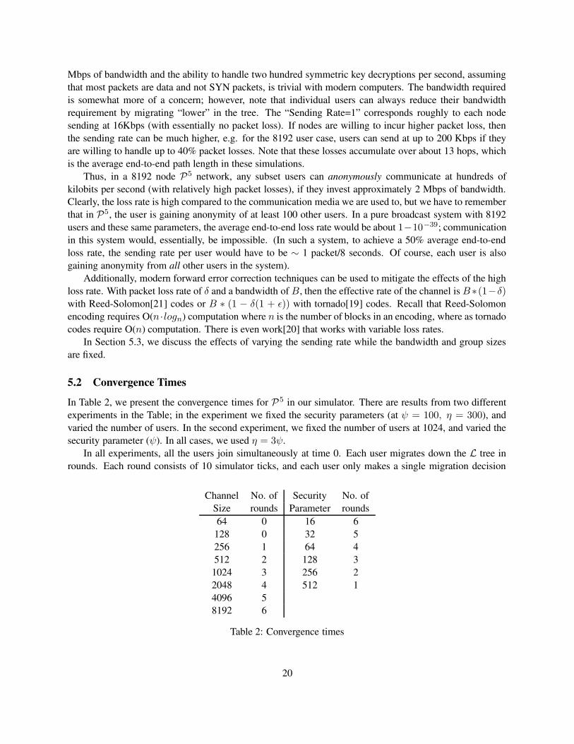
5.2 Convergence TimesIn Table 2, we present the convergence times for P 5 in our simulator. There are results from two differentexperiments in the Table; in the experiment we fixed the security parameters (at ψ = 100, η = 300), andvaried the number of users. In the second experiment, we fixed the number of users at 1024, and varied thesecurity parameter (ψ). In all cases, we used η = 3ψ.
In all experiments, all the users join simultaneously at time 0. Each user migrates down the L tree inrounds. Each round consists of 10 simulator ticks, and each user only makes a single migration decision
Channel No. of Security No. ofSize rounds Parameter rounds64 0 16 6
128 0 32 5256 1 64 4512 2 128 31024 3 256 22048 4 512 14096 58192 6
Table 2: Convergence times
20
in any one round. As expected, the convergence times increase as the number of users increase (or the ψparameter is decreased) since each user settles “lower” down in L. However, in all cases the number ofrounds to converge is given by max{0, logN − log ψ}.
5.3 Noise and Signal GenerationIn Figure 15, we vary the sending rate while keeping all other parameter fixed. We monitor a single sender–receiver pair, and report the observed packet loss. We use the two base sending rates from Section 5.1, andlinearly increase these rates by the rate multipliers plotted on the x-axis, while keeping the link bandwidthsconstant. As expected, the drop rates increase linearly with increases in sending rate. Interestingly, thenon-uniform drop rates perform slightly better as the sending rates increase.
In Figure 16, we repeat the same experiment and vary the number of sender-receiver pairs in the system.The rest of the users still generate noise at the same rate (log S/S). We plot the average drop rate across allof the sender-receiver pairs, and as above, the error bars denote 95% confidence intervals. As expected, thedrop rate is not affected by the number of sender–receiver pairs, and thus, no extra information is divulged toa passive observer when more people in the system communicate. We have also experimented with differentvalues of ψ and η. As expected, the drop rate increases as users choose higher values of the securityparameters, since they are mapped to larger broadcast channels.
6 Related WorkWe discuss prior work related to P5. Previous work can be broken down into work relating to the DiningCryptographers problem, Mixes, and other systems that provide anonymity over the Internet. We thensummarize existing work in Table 3.
6.1 Dining CryptographersThe Dining Cryptographers (DC-net) protocol [7] provides sender anonymity under an adversary modelsimilar to P5. DC-Net assumes a public key infrastructure, and users send encrypted broadcasts to theentire group, thus achieving receiver anonymity. However, unlike P 5, all members of the group are madeaware of when a message is sent, so Dining Cryptographers does not have the same level of sender-receiveranonymity. Also, in DC-net, only one user can send at a time, so it takes additional bandwidth to handlereservations, collisions, and contention [27]. Lastly, a DC-net participant fixes its anonymity versus band-width trade off when joining the system, and there are no provisions to rescale that trade off when othersjoin the system.
6.2 MixesA mix is a process that provides anonymity via packet re-shuffling. Encrypted messages are sent to a ma-chine, the mix, are batched, then decrypted and resent to their destinations in concert, thereby obscuringthe originator of the message. Mixes were introduced by Chaum in [6], but were improved upon in [5, 16].Mixes work best in series, and need a constant amount of traffic to avoid delay while preserving anonymity.P5 does both by creating a hierarchy of mixes, and the constant stream of signal and noise packets serve tokeep the mixes operational.
Of particular note is Mixminion[10] in which a user chooses a route through a set of mixes to a des-tination. Receiver anonymity is provided by registering a pseudonym at a nymserver, and publishing the
21

location of the nymserver. Messages are queued at the nymserver until such time as the recipient makes ananonymous connection to the nymserver to retrieve the messages. Further, Mixminion uses key rotation,2 legged paths, and timed dynamic-pool batching to mitigate replay attacks, tagging attacks, and blendingattacks respectively. They use dummy traffic between mixes for further mitigate the blending attack, but donot use end to end dummy traffic and cede that Mixminion is vulnerable to a long term correlation attack.
In contrast to Mixminion, P5 uses the same adversarial model, but is not vulnerable to the long termcorrelation attack. By broadcasting dummy/noise traffic end to end at a fixed rate, all nodes send andreceive a constant rate of traffic, defeating the correlation. Additionally, by using broadcast channels, P 5isnot vulnerable to replay, tagging, or blending attacks. Of course, P 5’s broadcast channels are less efficientthan Mixminion’s multi-hop unicast traffic, but users of P 5 can locally configure the level of inefficiency.Also, Mixminion targets high latency tolerant applications such as e-mail, where P 5 is a general purposeanonymous network layer suitable for all applications.
6.3 Recent Internet-based Anonymous Communications WorkWe describe four anonymity protocols that can be implemented over the Internet.
Xor-Trees Like P5, Xor-Trees [11] provides sender-, receiver-, and sender-receiver anonymity. How-ever, unlike P5, Xor-Trees do not admit a per user anonymity versus communications efficiency trade off.Also, like in DC-net, only a single user may send at any one time in an Xor-Tree. Thus, in an Xor-Tree,performance degrades due to collisions as the number of users increase.
Sender Anonymity Protocols Both Crowds [22] and the more recent Hordes [26] provide strictly senderanonymity. The basic idea in both these systems is similar to Onion Routing [14] and Tarzan [12], inwhich messages between communicating users are routed on an application-layer overlay using paths thatare either randomly or sender chosen to obscure the origin. The receiver cannot resolve the sender of aparticular message since messages take different, potentially randomly chosen, routes through the network.However, none of these systems provide anonymity when confronted by a passive observer who can mountstatistical attacks by tracing and correlating packets throughout the network over time. Additionally, noneof these systems provide receiver anonymity. However, any of these protocols can be adapted to providereceiver anonymity by using an anonymous proxy [23]. Aside from the scalability issues of having all ofthe users send their communications through a single server, users of an anonymous proxy system explicitlygive up sender-receiver anonymity to the connecting proxy.
FreeNet FreeNet [9] provides an anonymous publish-subscribe system over the Internet using an application-layer overlay, much like P5. However, FreeNet is designed for anonymous storage and retrieval, and theanonymity issues for such a system are different than a system like P 5 that provides anonymity when com-municating parties are on-line. There is no notion of noise or signal, etc., and the major issues in FreeNetare decoupling/hiding authorship from a particular document, and providing fault-tolerant anonymous avail-ability for a set of static documents.
6.4 SummaryThe capabilities of the above systems are summarized in Table 3. The columns “Sender”, “Receiver”, and“Sender-Receiver” refer to the systems ability to provide sender, receiver, and sender-receiver anonymity,
22
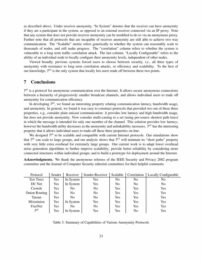
as described above. Under receiver anonymity, “In System” denotes that the receiver can have anonymityif they are a participant in the system, as opposed to an external receiver connected via an IP proxy. Notethat any system that does not provide receiver anonymity can be modified to do so via an anonymous proxy.Further note that all protocols that are incapable of receiver anonymity are still able to achieve two waycommunication. The “Scalable” metric refers generically to whether the system can reasonably scale tothousands of nodes, and still make progress. The “correlation” column refers to whether the system isvulnerable to a long term traffic correlation attack. The last column, “Locally Configurable” refers to theability of an individual node to locally configure their anonymity levels, independent of other nodes.
Viewed broadly, previous systems forced users to choose between security, i.e., all three types ofanonymity with resistance to long term correlation attacks, or efficiency and scalability. To the best ofour knowledge, P5 is the only system that locally lets users trade off between these two points.
7 ConclusionsP5 is a protocol for anonymous communication over the Internet. It allows secure anonymous connectionsbetween a hierarchy of progressively smaller broadcast channels, and allows individual users to trade offanonymity for communication efficiency.
In developing P5, we found an interesting property relating communication latency, bandwidth usage,and anonymity. In general, we found it was easy to construct protocols that provided two out of these threeproperties, e.g., consider plain unicast communication: it provides low latency and high bandwidth usage,but does not provide anonymity. Now consider multi-casting to a set (using per-source shortest path trees)in which the message is intended for only one member of the channel. This solution provides low latency;however the bandwidth utility decreases as the anonymity and unlinkability increases. P 5 has the interestingproperty that it allows individual users to trade-off these three properties on-line.
We designed P5 to be scalable and compatible with current Internet protocols. Our simulations showthat P5 can scale to large groups, and our analysis shows that P 5 will maintain its “short paths” propertywith very little extra overhead for extremely large groups. Our current work is to adapt lower overheadnoise generation algorithms to further improve scalability; provide better reliability by considering moreconnected structures within individual groups; and to build a prototype for deployment around the Internet.
Acknowledgments. We thank the anonymous referees of the IEEE Security and Privacy 2002 programcommittee and the Journal of Computer Security editorial committees for their helpful comments.
Protocol Sender Receiver Sender-Receiver Scalable Correlation Locally ConfigurableXor Trees Yes In System Yes No No NoDC Net Yes In System Yes No No NoCrowds Yes No No Yes Yes Yes
Onion Routing Yes No No Yes Yes YesTarzan Yes No No Yes Yes Yes
Mixminion Yes In System Yes Yes Yes YesFreeNet Yes No No Yes Yes Yes
P5 Yes In System Yes Yes No Yes
Table 3: Summary of Capabilities of Various Anonymity Protocols
23
References[1] http://www.epic.org/privacy/carnivore.
[2] NTRU Performance Numbers. http://www.ntru.com/cryptolab/faqs.htm.
[3] Pen Registers and Trap and Trace Devices. http://www.usdoj.gov/criminal/cybercrime/pentrap3121 3127.htm.
[4] www.echelonwatch.org.
[5] O. Berthold, A. Pfitzmann, and R. Standke. The disadvantage of Free MIX Routes and How to Over-come Them. pages 30–45. Designing Privacy Enchancing Technologies: Workshop on Design Issuein Anonymity and Unobservability, 2000.
[6] D. Chaum. Untraceable Electronic Mail, Return Addresses, and Digital Pseudonyms. Communicationsof the ACM, 24(2), 1981.
[7] D. Chaum. The Dining Cryptographers Problem: Unconditional Sender and Recipient Untraceability.Journal of Cryptology, 1(1):65–75, 1988.
[8] H. Chernoff. A measure of asymptotic efficiency for tests of a hypothesis based on the sum of obser-vations. Annals of Mathematical Statistics, 1952.
[9] I. Clarke, O. Sandberg, B. Wiley, and T. Hong. Freenet: A Distributed Anonymous Information Storageand Retrieval System. In International Workshop on Design Issues in Anonymity and Unobservability,LNCS 2009, 2001.
[10] G. Danezis, R. Dingledine, and N. Mathewson. Mixminion: Design of a Type III Anonymous RemailerProtocol. IEEE - Security and Privacy Symposium, 2003.
[11] S. Dolev and R. Ostrovsky. Xor-Trees for Efficient Anonymous Multicast Receiption. Advances inCryptography - CRYPTO 97, 1997.
[12] M. J. Freedman, E. Sit, J. Cates, and R. Morris. Introducing Tarzan, A Peer-to-Peer AnonymizingNetwork Layer. In Proceedings of 1st Intl. Workshop on Peer-to-Peer Systems, March 2003.
[13] V. Fuller, T. Li, J. Yu, and K. Varadhan. Rfc 1519 - classless inter-domain routing (cidr): an addressassignment and aggregation strategy, September 1993.
[14] D. M. Goldschlag, M. G. Reed, and P. F. Syverson. Onion routing for anonymous and private internetconnections. Communications of the ACM, 42(2), February 1999.
[15] W. Hoeffding. Probability inequalities for sums of bounded random variables. American StatisticalAssociation Journal, 58, 1963.
[16] A. Jerichow, J. Muller, A. Pfitzmann, B. Pfitzmann, and M. Waidner. Real-Time MIXes: A Bandwidth-Efficient Anonymity Protocol. IEEE Journal on Selected Areas of Communication, 1998.
[17] P. Karger. Non-discretionary access control for decentralized computing. Master’s thesis, Laboratoryfor Computer Science, Massachusetts Institute of Technology, 1977.
[18] G. Lindsay. The government is reading your e-mail. TIME DIGITAL DAILY, June 1999.
24
[19] M. Luby, M. Mitzenmacher, A. Shokrollahi, and D. Spielman. Efficient erasure correcting codes. IEEETransactions on Information Theory, 47:569–584, February 2001.
[20] P. Maymounkov. Online Codes. Technical report, New York University, 2002.
[21] I. Reed and G. Solomon. Polynomial codes over certain finite fields. J. Soc. Indust. Appl. Math,8:300–304, 1960.
[22] M. K. Reiter and A. D. Rubin. Crowds: Anonymity for Web Transactions. ACM Transactions onInformation and System Security, 1(1):66–92, 1998.
[23] V. Scarlata, B. Levine, and C. Shields. Responder Anonymity and Anonymous Peer-to-Peer FileSharing. In Proceedings of IEEE International Conference on Network Protocols (ICNP) 2001., 2001.
[24] B. Schneier. http://www.schneier.com/crypto-gram-9912.html.
[25] R. Sherwood, B. Bhattacharjee, and A. Srinivasan. P5: A Protocol for Anonymous Communications.In In the Proceedings of IEEE Security and Privacy Symposium, 2002.
[26] C. Shields and B. N. Levine. A Protocol for Anonymous Communication Over the Internet. In Pro-ceedings of the 7th ACM Conference on Computer and Communications Security (CCS-00), pages33–42, N.Y., Nov. 1–4 2000. ACM Press.
[27] M. Waidner and B. Pfitzmann. The Dining Cryptographers in the Disco: Unconditional Sender andRecipient Untraceability with Computationally Secure Serviceability. In J.-J. Quisquater and J. Vande-walle, editors, Advances in Cryptology—EUROCRYPT 89, volume 434 of Lecture Notes in ComputerScience, page 690, April 1989.
[28] M. Wright, M. Adler, B. Levine, and C. Shields. An analysis of the degradation of anonymous proto-cols. 2002.
A Updates to Security and Privacy 2002 PaperThere are significant updates to the P5 protocol from the original conference paper[25]. One of the mostcommon critiques of the original protocol was the need for one public key decryption per packet. Thesolution, as described in Section 2.4, is to use the public key cryptography to negotiate a symmetric sessionkey. This technique can be used to arbitrarily reduce the CPU load on a node, at the cost of increasedconnection initiation latency.
Another problem with the original protocol was its failure to account for the fact that new nodes in thesystem do not increase the security of previously communicating nodes. For example, Alice joins the systemat a certain channel in L that meets her security and efficiency requirements, and she starts communicatingwith Bob. Then, over time, enough new nodes join the same channel, and this causes the channel to exceedAlice’s efficiency parameter. Alice decides to go down in the tree (Section 3.4) to preserve her efficiency.However, if we assume that Bob is colluding with the global passive attacker (as per our adversarial model),then as soon as Alice starts communicating, Bob tells the passive adversary which channel she is in, andthen the passive adversary can enumerate all of the nodes of Alice’s old channel. From there, the adversaryknows that any new nodes that join the same channel are not Alice. But, when Alice goes down one level inthe logical tree to a new, smaller channel, her anonymity is not the size of the new channel, but the size of
25
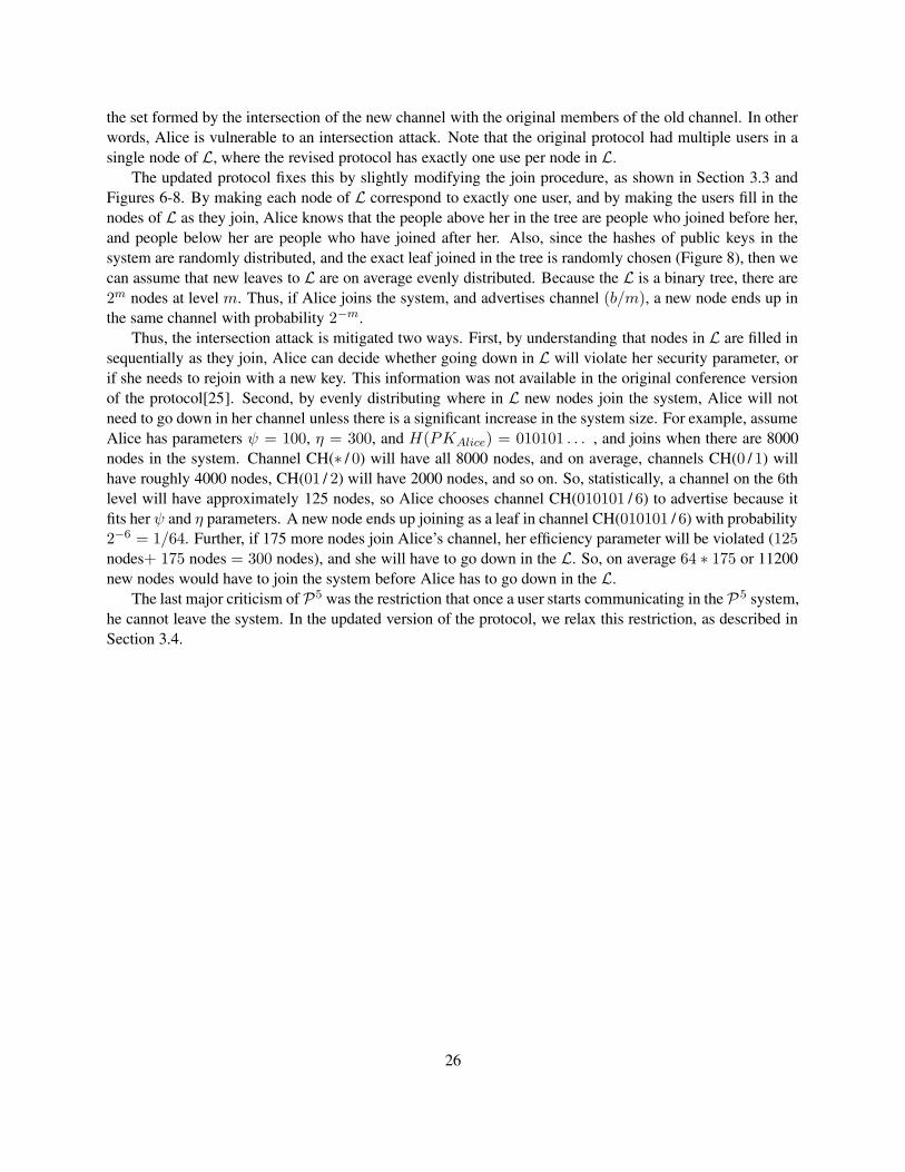
the set formed by the intersection of the new channel with the original members of the old channel. In otherwords, Alice is vulnerable to an intersection attack. Note that the original protocol had multiple users in asingle node of L, where the revised protocol has exactly one use per node in L.
The updated protocol fixes this by slightly modifying the join procedure, as shown in Section 3.3 andFigures 6-8. By making each node of L correspond to exactly one user, and by making the users fill in thenodes of L as they join, Alice knows that the people above her in the tree are people who joined before her,and people below her are people who have joined after her. Also, since the hashes of public keys in thesystem are randomly distributed, and the exact leaf joined in the tree is randomly chosen (Figure 8), then wecan assume that new leaves to L are on average evenly distributed. Because the L is a binary tree, there are2m nodes at level m. Thus, if Alice joins the system, and advertises channel (b/m), a new node ends up inthe same channel with probability 2−m.
Thus, the intersection attack is mitigated two ways. First, by understanding that nodes in L are filled insequentially as they join, Alice can decide whether going down in L will violate her security parameter, orif she needs to rejoin with a new key. This information was not available in the original conference versionof the protocol[25]. Second, by evenly distributing where in L new nodes join the system, Alice will notneed to go down in her channel unless there is a significant increase in the system size. For example, assumeAlice has parameters ψ = 100, η = 300, and H(PKAlice) = 010101 . . . , and joins when there are 8000nodes in the system. Channel CH(∗ / 0) will have all 8000 nodes, and on average, channels CH(0 / 1) willhave roughly 4000 nodes, CH(01 / 2) will have 2000 nodes, and so on. So, statistically, a channel on the 6thlevel will have approximately 125 nodes, so Alice chooses channel CH(010101 / 6) to advertise because itfits her ψ and η parameters. A new node ends up joining as a leaf in channel CH(010101 / 6) with probability2−6 = 1/64. Further, if 175 more nodes join Alice’s channel, her efficiency parameter will be violated (125nodes+ 175 nodes = 300 nodes), and she will have to go down in the L. So, on average 64 ∗ 175 or 11200new nodes would have to join the system before Alice has to go down in the L.
The last major criticism of P5 was the restriction that once a user starts communicating in the P 5 system,he cannot leave the system. In the updated version of the protocol, we relax this restriction, as described inSection 3.4.
26
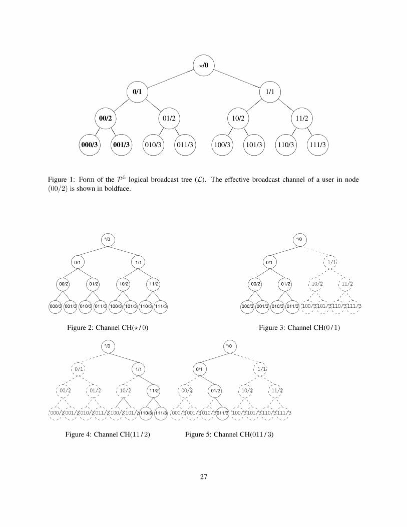
?/0����
0/1����
00/2����
000/3������ TT
001/3����,
,, lll
01/2����
010/3������ TT
011/3����
!!!!!!!! aaaaaaaa1/1��
��
10/2����
100/3������ TT
101/3����,
,, lll
11/2����
110/3������ TT
111/3����
Figure 1: Form of the P5 logical broadcast tree (L). The effective broadcast channel of a user in node(00/2) is shown in boldface.
000/3 001/3 010/3 011/3 100/3 101/3 110/3 111/3
00/2 01/2 10/2 11/2
0/1 1/1
*/0
Figure 2: Channel CH(? / 0)
000/3 001/3 010/3 011/3 100/3 101/3 110/3 111/3
00/2 01/2 10/2 11/2
0/1 1/1
*/0
Figure 3: Channel CH(0 / 1)
000/3 001/3 010/3 011/3 100/3 101/3 110/3 111/3
00/2 01/2 10/2 11/2
0/1 1/1
*/0
Figure 4: Channel CH(11 / 2)
000/3 001/3 010/3 011/3 100/3 101/3 110/3 111/3
00/2 01/2 10/2 11/2
0/1 1/1
*/0
Figure 5: Channel CH(011 / 3)
27
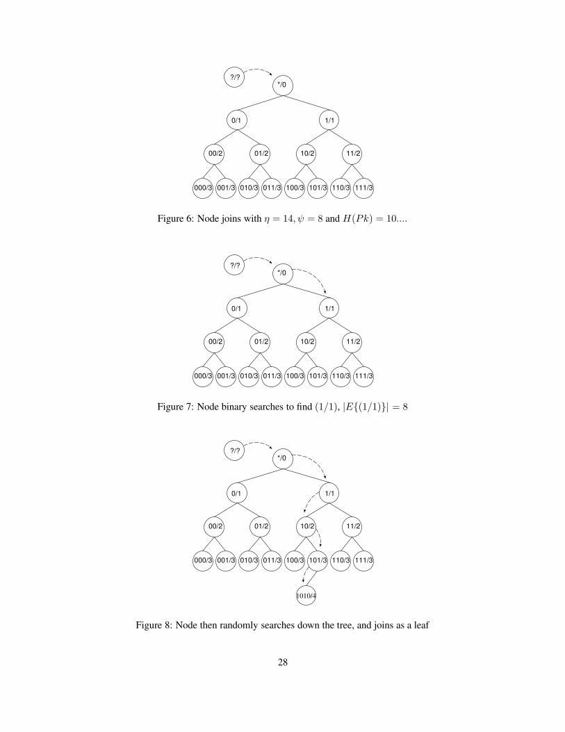
000/3 001/3 010/3 011/3 100/3 101/3 110/3 111/3
00/2 01/2 10/2 11/2
0/1 1/1
*/0?/?
Figure 6: Node joins with η = 14, ψ = 8 and H(Pk) = 10....
000/3 001/3 010/3 011/3 100/3 101/3 110/3 111/3
00/2 01/2 10/2 11/2
0/1 1/1
*/0?/?
Figure 7: Node binary searches to find (1/1), |E{(1/1)}| = 8
000/3 001/3 010/3 011/3 100/3 101/3 110/3 111/3
00/2 01/2 10/2 11/2
0/1 1/1
*/0?/?
1010/4
Figure 8: Node then randomly searches down the tree, and joins as a leaf
28
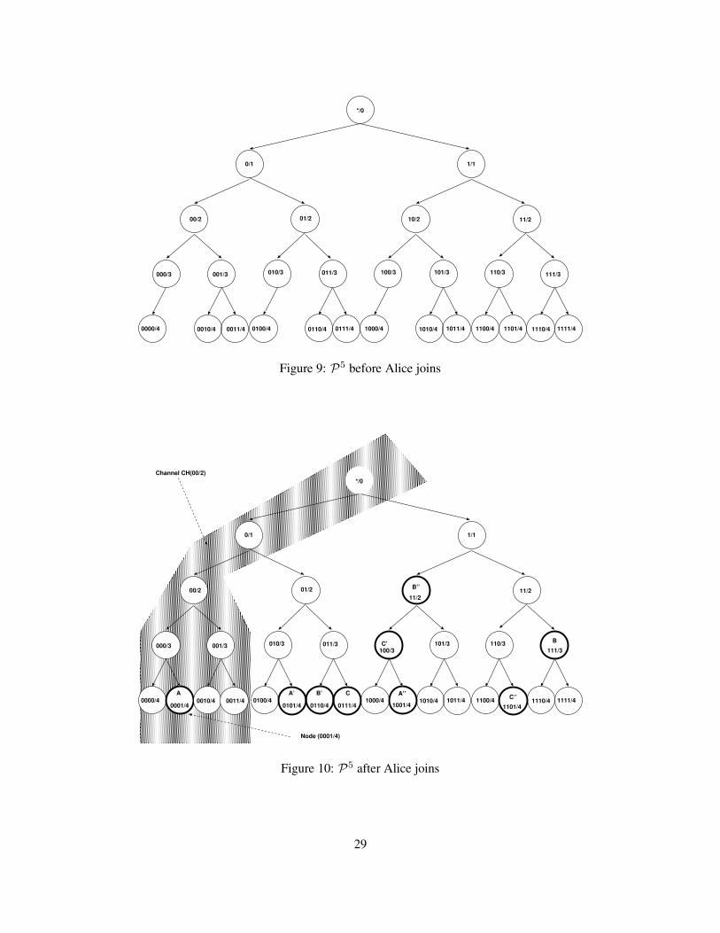
*/0
0/1 1/1
00/2 01/2 10/2 11/2
000/3 001/3 010/3 011/3 100/3 101/3 110/3 111/3
0000/4 0010/4 0011/4 0100/4 0110/4 0111/4 1000/4 1010/4 1011/4 1100/4 1101/4 1110/4 1111/4
Figure 9: P5 before Alice joins
1/1
01/2 B’’ 11/2
010/3 011/3 C’ 101/3 110/3 B
0100/4 1000/4A’’
1010/4 1011/4 1100/4 C’’ 1110/4 1111/4A’ B’ C
111/3
0101/4 0110/4 0111/4
100/3
11/2
1001/4 1101/4
Node (0001/4)
Channel CH(00/2)*/0
0/1
00/2
000/3 001/3
0000/4 0010/4 0011/4A
0001/4
Figure 10: P5 after Alice joins
29
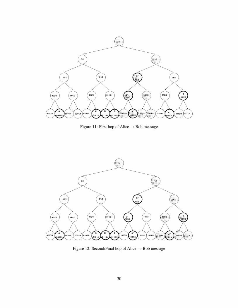
*/0
0/1 1/1
00/2 01/2 B’’ 11/2
000/3 001/3 010/3 011/3 C’ 101/3 110/3 B
0000/4 0010/4 0011/4 0100/4 1000/4A’’
1010/4 1011/4 1100/4 C’’ 1110/4 1111/4A A’ B’ C
111/3
0001/4 0101/4 0110/4 0111/4
100/3
10/2
1001/4 1101/4
Figure 11: First hop of Alice → Bob message
*/0
0/1 1/1
00/2 01/2 B’’ 11/2
000/3 001/3 010/3 011/3 C’ 101/3 110/3 B
0000/4 0010/4 0011/4 0100/4 1000/4A’’
1010/4 1011/4 1100/4 C’’ 1110/4 1111/4A A’ B’ C
111/3
0001/4 0101/4 0110/4 0111/4
100/3
10/2
1001/4 1101/4
Figure 12: Second/Final hop of Alice → Bob message
30
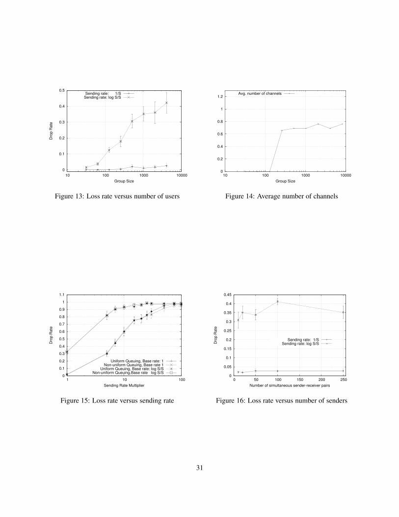
0
0.1
0.2
0.3
0.4
0.5
10 100 1000 10000
Drop
Rat
e
Group Size
Sending rate: 1/SSending rate: log S/S
Figure 13: Loss rate versus number of users
0
0.2
0.4
0.6
0.8
1
1.2
10 100 1000 10000Group Size
Avg. number of channels
Figure 14: Average number of channels
0
0.1
0.2
0.3
0.4
0.5
0.6
0.7
0.8
0.9
1
1.1
1 10 100
Drop
Rat
e
Sending Rate Multiplier
Uniform Queuing, Base rate: 1Non-uniform Queuing, Base rate 1
Uniform Queuing, Base rate: log S/SNon-uniform Queuing,Base rate log S/S
Figure 15: Loss rate versus sending rate
0
0.05
0.1
0.15
0.2
0.25
0.3
0.35
0.4
0.45
0 50 100 150 200 250
Drop
Rat
e
Number of simultaneous sender-receiver pairs
Sending rate: 1/SSending rate: log S/S
Figure 16: Loss rate versus number of senders
31


![Scalable Link-Based Relay Selection for Anonymous Routingboonloo/papers/pets09.pdfTor [7] path selection algorithm sorts relays in increasing order of bandwidth and computes the sum](https://img.pdfslide.net/doc/110x75/5edfbd60ad6a402d666b0ed1/scalable-link-based-relay-selection-for-anonymous-routing-boonloopapers-tor-7.jpg)
![PIR-Tor: Scalable Anonymous Communication Using …pmittal/publications/pirtor-usenix11.pdfPIR-Tor: Scalable Anonymous Communication Using Private Information Retrieval ... Salsa [29]](https://img.pdfslide.net/doc/110x75/5b1e61b57f8b9a901f8b8f97/pir-tor-scalable-anonymous-communication-using-pmittalpublicationspirtor-usenix11pdfpir-tor.jpg)


![Design of Anonymous Endorsement System in Hyperledger Fabric · Hyperledger Fabric is one of the most popular open-source permissioned blockchain frameworks[3]. It is quite scalable](https://img.pdfslide.net/doc/110x75/5ec65e753964fa287365d579/design-of-anonymous-endorsement-system-in-hyperledger-fabric-hyperledger-fabric.jpg)