Embed Size (px)
Citation preview
Pacific Sea Breeze Marine Products Model : PSB-12K Marine 12,000 BTU Heat Pump AC Powered Self Contained Heat Pump with Adjustable Horiz/Vert Airflow and Water Cooled Condenser for Marine Heating and Cooling
The PSB-Heat Pump Family is a family of self contained unit intended for use on small watercraft or for limited spaces within larger watercraft. These units can also be used in solar installation on land where off the grid efficiency is important. Features High Efficiency Compressor Adjustable Blower Direction High Efficiency Evaporator Coil Stainless Steel Drain Pan Reverse Cycle Heat Pump Environmentally Friendly R-410 Refrigerant
Model Unit PSB-12K
Rated cooling capacity Btu/h 12,000
Input Power(cooling) W 1000
AMPS @ 110 VAC 60Hz A 8.1
Input Power(heating) W 1100
AMPS @ 110 VAC 60Hz 9.5
Weight lbs
L 355 / 14
W 465 / 18.3 Dimension
H
mm / in
320 / 12.6
Model PSB-9K
Minimum Return Air Grill Area(cm2) 780
Minimum Discharge Air Grill Area(cm2) 460
Flexmount Duct Inner Diameter(mm) Φ175
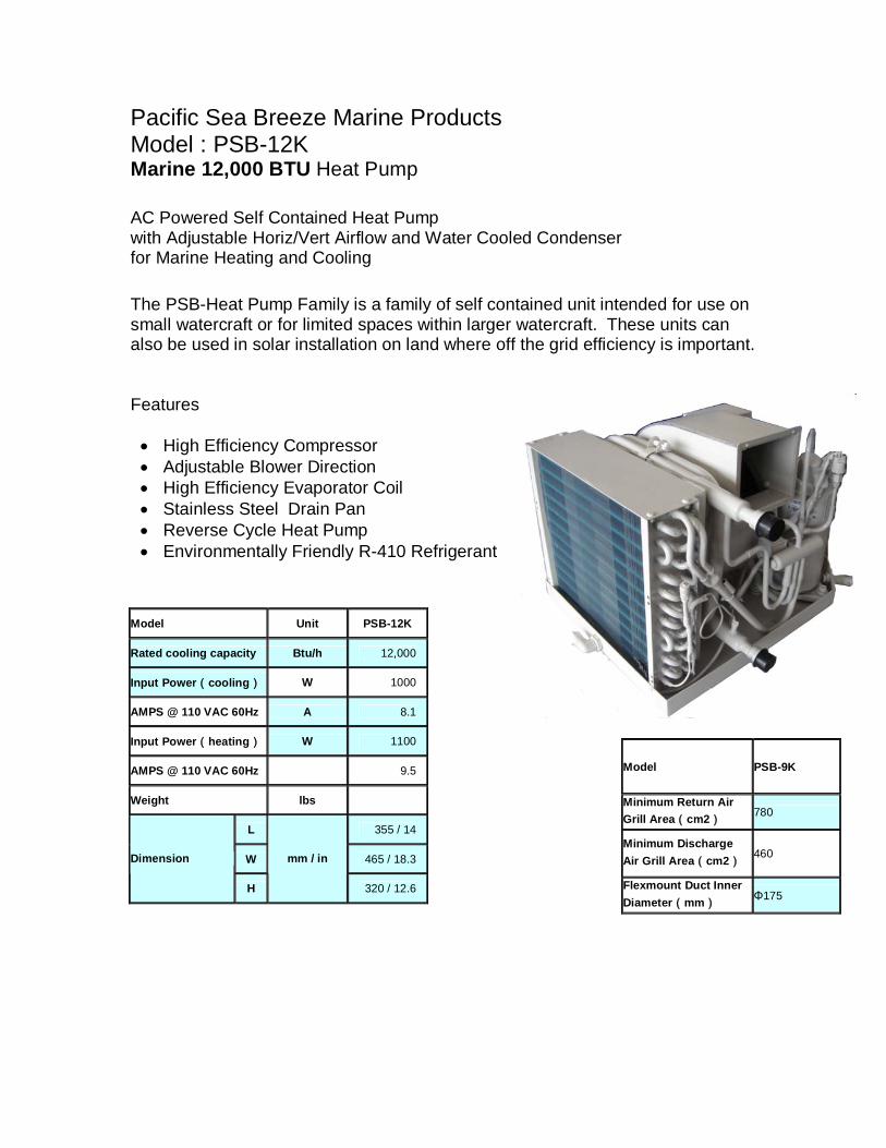
Model PSB-7K PSB-9K PSB-10K PSB-12K PSB-16K PSB-18K PSB-24
Minimum Return Air Grill Area(cm2)
650 650 650 780 1200 1200 1450
Minimum Discharge Air Grill Area(cm2)
380 380 380 460 600 600 780
Flexmount Duct Inner Diameter(mm)
Φ150 Φ150 Φ150 Φ175 Φ200 Φ200 Φ225
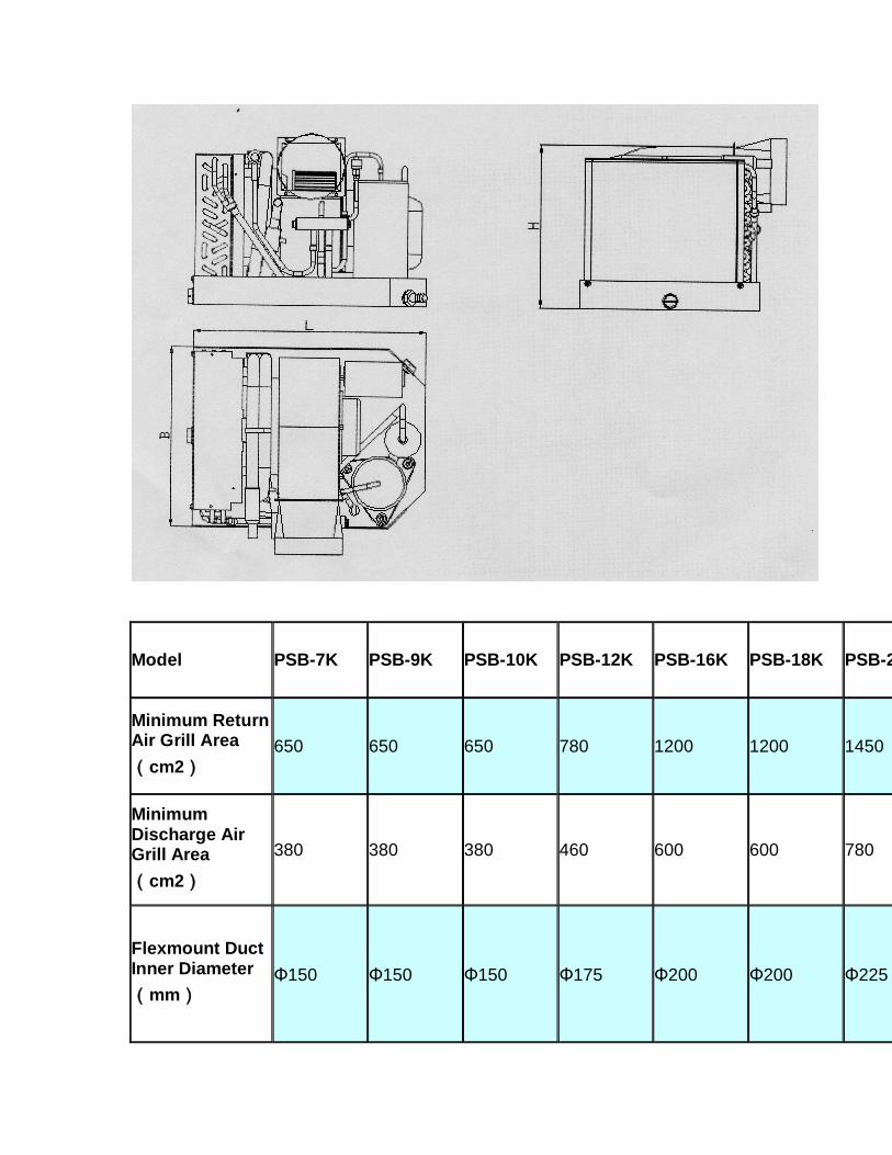
Installation
Installation location: Self contained units MUST be placed inside the air conditioned area of the vessel - NEVER let them suck bacteria laden bilge fumes or possibly the carbon monoxide laden air from an engine room.
We recommend every vessel with a generator has high quality CO (carbon monoxide) detectors installed.
The units must also recirculate the air conditioned air of the boat, not hot/humid fresh air. Think of an air conditioner as a powerful vacuum cleaner sucking air out of whatever compartment it is in and blowing this air through the ductwork. Every pass of air over the evaporator will drop the temperature about 18-22°F- no unit can take in 95% humidity, 95°F air and discharge it at a dry 55°F!
Typical installation locations are under a settee, under a bunk, at the floor or ceiling of a closet, under the V berth, on a shelf at the ceiling level, etc. Like all HVAC equipment, it is good form to place the slowly dissolving chlorine tablets
such as "Kontrol" in the wet drain pan to combat mold/mildew etc. a few times a year.
You can install a unit in an engine room or lazarette if you box it off so that the return air comes ONLY from the inside of the vessel - it must be airtight from the engine room or liner of the boat.
The most common installation mistake is to leave even a small opening such as a 1" crack that is open to the liner of the boat - you will end up mixing for example 50% bilge air with the air conditioned air - the unit will never catch up and sweat profusely from the humidity - the compartment must be air tight from the bilge or liner.
Discharge air ducting: To greatly simplify the discharge ducting we supply aluminum plenums that bolt directly onto the blower flange that have the correct number of 4" collars on them for the size of the unit. The 4" flexible ducting attaches to these collars with a plastic wire-tie, and terminates at the 4" discharge grills. Do not block off any ducts - this will reduce the airflow over the evaporator which may cause the unit to cycle off and on via the freeze control switch.
The most desirable location for our grills is on a bulkhead near the ceiling. In fact, if you have trouble running the ducting you can place the discharge grills right next to each other and simply point them in different directions. The cold air will bounce off of the headliner and gently drop down into the room, and our blowers are powerful enough to de-stratify the air in both the heat and cool mode if properly sized for the application.
The discharge air will normally travel about 8-10', so of course you will have to run a duct to the V for example if the unit is in the main salon and you want to cool the V berth.
Common mistake: Make sure you get the cold/dry discharge air away from the return air intake of the a/c. If you place your unit in the V for example, don't install a discharge grill in the V because the V is relatively small and may be 70° when the main salon is 85°, causing the compressor to cycle off on its' freeze control switch. We are working with approximately 20° temperature differentials: return air = 75°(24C), discharge air = 55°(13C), refrigerant = 35°(2C). To ascertain if you have properly ducted your discharge system, check the air temperature of the air at the return grill - it should be the same as the room temperature where the thermostat is located.
Because our units are so powerful for their size, we do not supply variable speed fans, however you will not be bothered at all by the fan noise - we even insulate our blower motors - these units are very quiet.
If you design your own ducting system, do not have excessive runs of ducting or restrict the air flow return. If inadequate air is passed over the evaporator, the unit will develop frost on the evaporator and will eventually ice up unless it is equipped with a freeze control, whereby it will cycle on and off.
Our units are designed to bring the air temperature down to about 70°F - if you try to attain a lower temperature you will either develop a freeze up or cycle on the freeze control.
Return air ducting: There is no need for return air ducting - these units are like vacuum cleaners, sucking air from whatever compartment they are in and blowing the cooled or heated air through the discharge duct-work system. If you use our pre-designed ducting system you will be assured of having the correct amount of air flow and air velocity to successfully de-stratify the air in a properly sized application without having excessive noise or uncomfortable drafts.
The blower motor and rotary compressors are air cooled and do get warm, therefore it's good form to have the return air travel over these components in route to the evaporator. There is no need to have the evaporator up against the return air grill, in fact it's better to have the opposite - make sure the evaporator has at least 2-3" of space from a bulkhead.
We manufacture vertical or side discharge units - although it is possible to change this after production it is difficult to do so and we don't recommend it.
Plumbing: The intake through hull should be as low as possible in the water in a location that is always underwater and not exposed to the backwash of the propellers whereby air bubbles could be ingested. Almost every marine air conditioning pump is a flooded volute pump and must be mounted below the waterline. For boats that are in dry storage, you may install a T fitting at the discharge of the pump with one line running to a vertical location with a valve for releasing the back pressure to simplify priming.
Frequently you can "T" off of a head intake, however we don't recommend having the a/c share a through hull fitting with any other pump such as the engine or generator because of the hazard of the more powerful impeller pump sucking air backwards through the a/c rather than water from the through-hull fitting, possibly overheating and damaging you equipment.
The units' discharge through hull fitting should be between 4" and 8" above the waterline - if below 4" it would have to be treated as a "below the waterline"
through hull and would be required to have a valve - above 8" the noise of the running water may be bothersome.
Care should be taken to avoid crimping the suction line. If long runs of plumbing are required or if the unit is placed well above the waterline you may end up with too much head pressure necessitating a higher volume pump. We have a variety of pumps in stock, and the charge to increase the GPM capacity is nominal - see our pump page.
The sea water requirements for cooling our equipment is about 200 gallons/hour/ton of air conditioning(12,000BTUs= one ton) at a maximum temperature of 100°F. The only metal the salt water touches is the inside of a 90/10 CuNi condensing tube which is inside a copper shell. We do not use a serrated, knurled or enhanced tube to increase the surface area because we find our slick inner tube to be less prone to trap debris and much more durable - we make up for this loss of surface area by extending the length of the condensing tube ensuring long-term trouble-free operation.
All of our condensing tubes are 5/8"OD, and for systems of up to about three tons of A/C (36,000 BTUs), a single 3/4" intake through hull set up is adequate - larger systems may need a 1" or larger, depending on the total GPH requirements.
In multiple unit installations, we often suggest using one large pump with a pump relay box whereby each unit has a 24 volt wire returning to the pump relay box (usually mounted by the pump), and if any one of the units engage, the pump will supply water to all of the units.
Depending on the number of units and pump size, we often run one 1" supply line from the pump from which 5/8" T's supply individual units. The sea water discharge from each unit can be individual by each unit or tied together into one or more discharge through hull fittings.
The condensate drain line should never be connected to the raw water discharge line- if there were a blockage in the discharge line, the raw water pump would pump raw water back into the drain pan and ultimately into the boat causing a sinking hazard.
The condensate drain line is a gravity line and the highest point of this line will determine the water level in the condensate pan. A common mistake is to have the condensate line run a couple of feet at the same level of the chassis - if there is any section even 1" above the bottom of the chassis, you will have excessive water in the drain pan. You should also consider heel angle when routing the condensate drain line. Ideally the condensate drain line will be sloping continuous down to a through h
Under normal operating conditions, the condenser (the copper tube within a tube on the unit) should be warm to the touch - if you cannot feel any heat in the condenser whatsoever when the compressor is running, you have too much cold water passing through it. This is only a problem in some areas where the water temperature is 40°F and the air temperature is 90°F! This can be remedied by installing a gate valve on the supply line at the unit to throttle down the water flow. Remember to never restrict the SUCTION side of a centrifugal pump, conversely there is no harm restricting the DISCHARGE side of a centrifugal pump.
If the condenser is too hot to hold your hand on constantly, you are not getting enough cooling water. This is not a very scientific way of determining water flow but it works. Most of our units have manually resettable high pressure switches on the condenser, whereby if the unit is operated without enough cooling water and the refrigerant pressure on the high side reaches the limit, the switch will activate, shutting down the compressor until it is manually reset by pushing in the button.
Electrical: We recommend the use of GFI (ground fault interrupt) breakers for any high voltage equipment near water, and always use stranded wire - never use solid core wire on any vessel because the motion of the vessel may eventually cause a failure and can be a serious fire hazard.
Be sure to use the proper size wire for our equipment. Undersized wire or poor dock/ship connections will result in a voltage drop that may damage the equipment and be a fire hazard.
Use a minimum 12 gauge power supply wire - never use 14 gauge for even our smallest units if wired 115 volt.
Be sure the breaker capacity is less than the current capability of the wire - for example, with a high quality #12 wire @120VAC, don't use a breaker of more than 30 amps. Use quality wire - cheap #12 wire may be rated at less than 30 amps, typically the larger number of strands and the higher the voltage capability of the wire determines its capacity - use wire rated at a minimum 600V.
Many marinas have inadequate wiring -we suggest you test the dock line voltage during peak loads -it may be 120 volts on a cool weekday morning and 90 volts on a hot weekend afternoon!
The high voltage block has three connections for the power supply and three connections for the pump - don't mix them up! This terminal block is clearly marked, however if you wish to confirm which is which, the heavier gauge wires
are the power in and the lighter gauge wires are the pump output terminals. With 120V systems, the black wire is your line (L), which goes to the circuit breaker, the white wire is your neutral (N), which goes to the neutral buss bar, and the green wire is always ground (G), which goes to your ground buss bar. With 230V systems there is usually no neutral, (the white wire) and there are two lines, one black(L1) and one red(L2), both of which must be on a dual terminal 230V breaker.
The low voltage terminal block connects to the digital control - we use the HVAC industry standard - red, white, green, yellow color code - any domestic thermostat will operate any of our equipment and you will never have to helicopter in a rocket scientist to figure out our digital control, in fact, one can cross all of these wires except the white for cool or all of the wires except the yellow for heat! The 24 volts for the digital control output is produced by an internal transformer in the a/c unit.
The internal electronics of our digital control are powered by two AA batteries, therefore these delicate components are not subject to line voltage spikes, etc. To replace these batteries simply remove the four #1 Phillips head screws on the face plate to access the batteries.
You will find a reset-able breaker on all of our equipment - safety is our primary concern and we strive to make our equipment as fool proof as possible.
The Pacific Sea Breeze Heat Pump utilizes the more efficient reverse cycle heating systems instead of the resistive heat strip heat that some units use.
The use of rotary or scroll compressors has greatly reduced the problems with "start up surge"- and we have further reduced this surge by installing as standard equipment, hard start capacitors on all units over 12,000BTU's(scroll compressors excluded - inherently negligible start up surge). Typically, the dinosaur like piston compressor have a 350% startup surge, the newer rotary compressors a 150% start up surge (without the hard start capacitor- about 120% with!) and the scroll compressors a mere 110% start up surge.
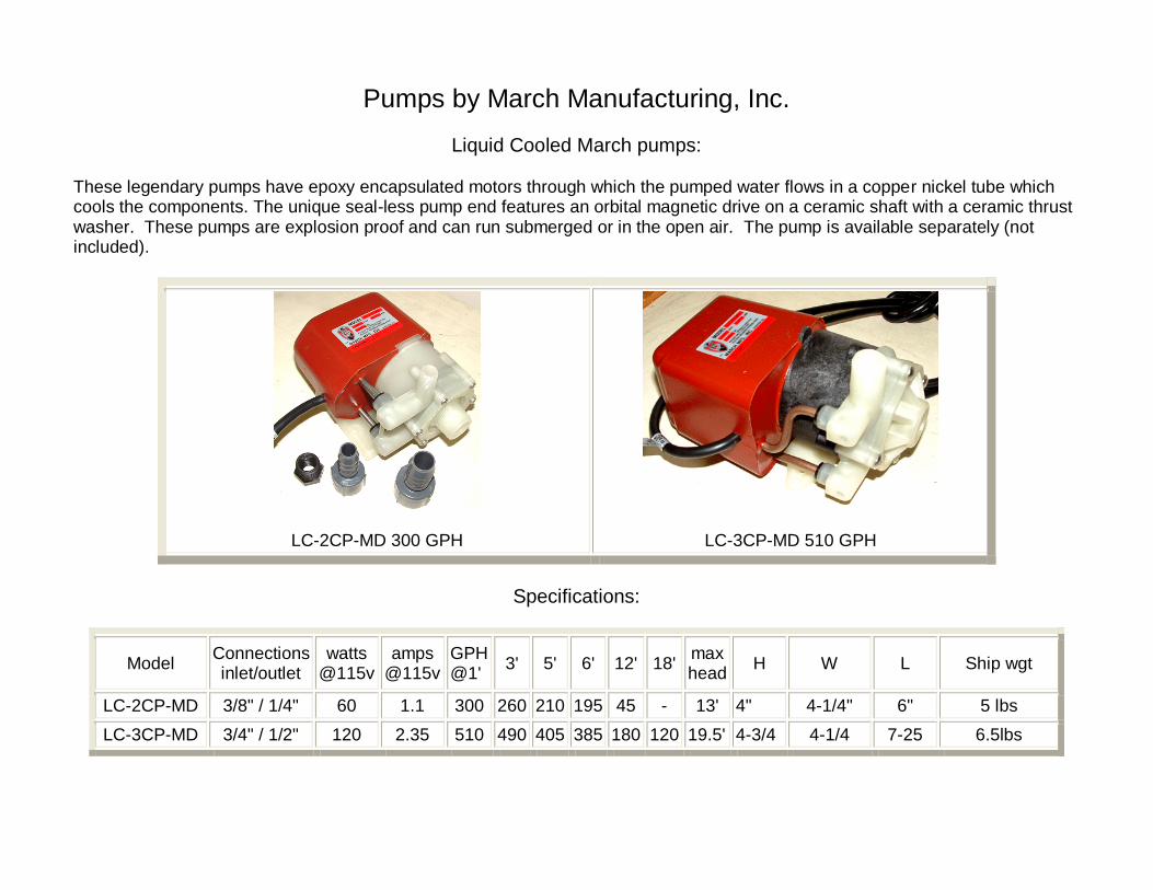
Pumps by March Manufacturing, Inc.
Liquid Cooled March pumps:
These legendary pumps have epoxy encapsulated motors through which the pumped water flows in a copper nickel tube which cools the components. The unique seal-less pump end features an orbital magnetic drive on a ceramic shaft with a ceramic thrust washer. These pumps are explosion proof and can run submerged or in the open air. The pump is available separately (not included).
LC-2CP-MD 300 GPH
LC-3CP-MD 510 GPH
Specifications:
Model Connections inlet/outlet
watts @115v
amps @115v
GPH @1' 3' 5' 6' 12' 18' max
head H W L Ship wgt
LC-2CP-MD 3/8" / 1/4" 60 1.1 300 260 210 195 45 - 13' 4" 4-1/4" 6" 5 lbs LC-3CP-MD 3/4" / 1/2" 120 2.35 510 490 405 385 180 120 19.5' 4-3/4 4-1/4 7-25 6.5lbs
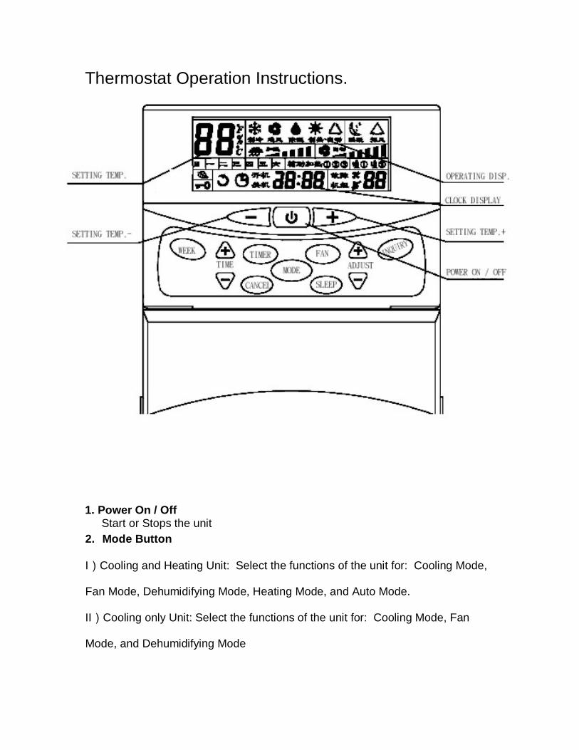
Thermostat Operation Instructions.
1. Power On / Off Start or Stops the unit
2. Mode Button
I)Cooling and Heating Unit: Select the functions of the unit for: Cooling Mode,
Fan Mode, Dehumidifying Mode, Heating Mode, and Auto Mode.
II)Cooling only Unit: Select the functions of the unit for: Cooling Mode, Fan
Mode, and Dehumidifying Mode
3. Fan Speed Button
Select the fan speed desire: Low, Medium, High and Auto
4. Day of the Week Display and Setting
In general, Day of the week Display Area should display the present day of the week. If
they are different, you may adjust it by “DAY” Button from Monday to Sunday.
5. Time Display and Setting
There is a real-time clock running in the system. In general, this real-time clock is
displayed in the Time Display Area. System time can be adjusted by Time+ and
Time-
6. Timer On and Timer Off
To program the Timer, press Timer On button or Timer Off button to change the
clock to the desired time for the unit being turned on or off.-
7. Sleep Button
Press to select the function of the unit for Sleep Mode.
If in the Fan Mode or Dehumidifying Mode, it is without this function.
This function will be canceled after the unit running 8 hours
8. Temperature setting and display
To program the designed temperature by TEMP.+ and TEMP.-, press the
TEMP+ or TEMP- until the desired room temperature appears on the LED, the
desired temperature range is from 16 degree to 31 degree. 6 seconds after
pressing the button, the unit will display the current room temperature.
9. Button Locking Mode
After 5 seconds that you press “SELECT” Button and “MODE” Button, the
system will be in the Button Locking Mode. You may quit from it by the same
manner.
In this mode, only Power On /off are effective.