Embed Size (px)
Citation preview
Page 1 of 14
Authorized Onsite Soil Evaluator I Professional Engineer Report for
Construction Permit Lot: Section: . Subdivision: Acreage: .91 +/-Acres
Property Location: Map Reference: GPIN:
Other Property ID:
Applicant I Client and Address:
Date of Report: 5/7/14
Revisions:
Contents /Index of this Report:
Site Layout I Construction Drawings Soil Summary Report Soil Profile Descriptions Construction Specifications AX20-RT Specifications Abbreviated Design Form Advantex Owner's Manual Septic Care & Maintenance Water Supply Design Specs
Certification Statement:
[8J Yes [8J Yes [8J Yes [8J Yes [8J Yes [8J Yes [8J Yes [8J Yes DYes
I hereby certify that the evaluations and/or designs contained herein were conducted in accordance with the Sewage Handling and Disposal Regulations (I2 V ACS-61 0), the Private Well Regulations ( 12 V ACS-630) and all other applicable laws, regulations and policies implemented by the Virginia Department of Health. I further certify that I currently possess any professional license required by the laws and regulations of the Commonwealth that have been duly issued by the applicable agency charged with licensure to perform the work contained herein. The work attached to this cover page has been conducted under an exemption to the practice of engineering, specifically the exemption in The Code of Virginia Section 54.1-402.A.Il .
I recommend a permit1 be approved2.
Rev: 9/07
Prepared by:
AOSE I P.E. Job Number:
Health Dept. ID No.:
Page(s):
0No 0No 0No 0No 0No 0No 0No 0No [8J No
A.O.S.E./ P.E Stamp Signature & Date
2 of 14
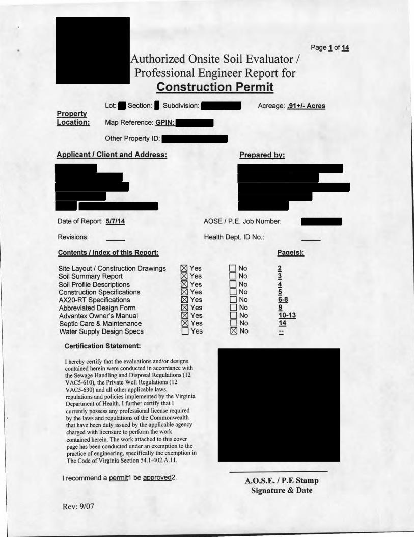
This plot is for Health Deportment review only. The inf ormotion provided herein does not constitute o certified survey, bwlding permH plot, or record plot. All matters pertaining to easements, setbacks, right of ways, etc, ore the owner's res. onsibi/J1.
f
!
Section •c: Block 'B:Lot 19
PB.60 Pg.13
/
ection fl : Block 'B:
I'
I
Lot 14
s 1
17
� -JL------------��s_o'_R_1/w,--') ________ ------.
� Proposed � Improvements on �
a1 DATE:5/7,/2014 ,M SCALE: 1 =40' l JOB NO:§ Pur:
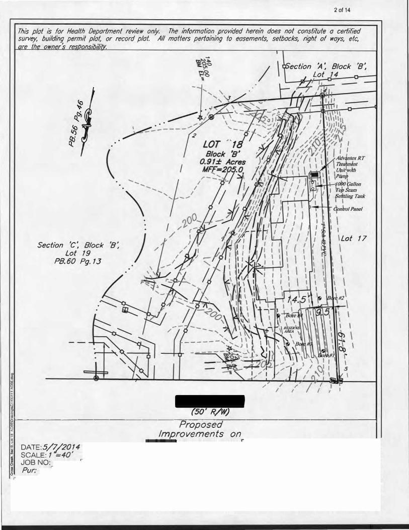
GENERAL INFORMATION
Date: 3/18/14
Applicant:
Submitted to� Health Department
Address:
Owner: Address:
Location:
Tax Map:� Subdivision: - Block/Section: I Lot: ■
SOIL INFORMATION SUMMARY 1. Position in landscape satisfactory: Yes No□
Describe: Side Slope
2. Slope: 6-8%
3. Depth to rock or impervious strata: Max. ___ " Min. 30" None =
4. Depth to seasonal water table (gray mottling or gray color): No [8J Yes □-
5. Free water present: No [8J
6. Soil percolation rate estimated:
7. Permeability test performed:
Yes O _range in inches
Yes [8J No D
Yes D No [8J
Texture group!! Estimated rate of� min/inch
lf yes, note type of test performed and attach _
1111
Site Approved: Drainfield to be placed at a depth of 18"at site designated on permit.D Site Disapproved:
Reasons for rejection: 1. O Position in landscape subject to flooding or periodic situation.2. O Insufficient depth of suitable soil over hard rock.3. D Insufficient depth of suitable soil to seasonable water table.4. D Rates of absorption to slow.5. O Insufficient area of acceptable soil for required drainfield, and/or Reserve Area.6. 0 Proposed system too close to well.7. □- (attach additional pages if necessary)
Rev: 9/07
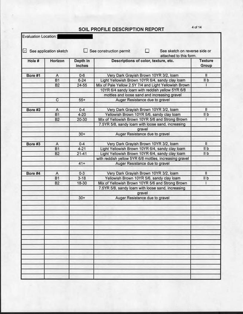
SOIL PROFILE DESCRIPTION REPORT 4 of 14
Evaluation Location:
0 See application sketch D See construction permit D See sketch on reverse side or attached to this form.
Hole# Horizon Depth in Descriptions of color, texture, etc. Texture inches Groull_
Bore #1 A 0-6 Verv Dark Grayish Brown 1 OYR 3/2, loam II B1 6-24 Light Yellowish Brown 1 OYR 6/4, sandy clay loam II b B2 24-55 Mix of Pale Yellow 2.5Y 7/4 and Liqht Yellowish Brown I
1 OYR 6/4 sandy loam with reddish yellow 5YR 6/8 mottles and loose sand and increasing gravel
c 55+ Auger Resistance due to gravel
Bore #2 A 0-4 Verv Dark Grayish Brown 1 OYR 3/2, loam II B1 4-20 Yellowish Brown 10YR 5/6, sandy clay loam II b B2 20-30 Mix of Yellowish Brown 10YR 5/6 and Stronq Brown I
7.5YR 5/8, sandy loam with loose sand, increasing gravel
30+ Auger Resistance due to oravel
Bore #3 A 0-4 Verv Dark Grayish Brown 1 OYR 3/2, loam II B1 4-21 Liqht Yellowish Brown 10YR 6/4, sandy clay loam II b B2 21-41 Liqht Yellowish Brown 10YR 6/4, sandy clay loam lib
with reddish yellow 5YR 6/8 mottles, increasing gravel 41+ Auger Resistance due to gravel
Bore #4 A 0-3 Very Dark Grayish Brown 1 OYR 3/2, loam II B1 3-18 Yellowish Brown 10YR 5/6, sandy clay loam lib B2 18-30 Mix of Yellowish Brown 1 OYR 5/6 and Strono Brown I
7.5YR 5/8, sandy loam with loose sand, increasinq qravel
30+ Auqer Resistance due to qravel
-
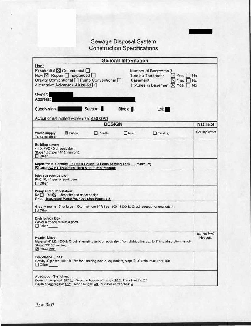
Sewage Disposal System Construction Specifications
General Information
Use: Residential r8l Commercial DNew r8l Repair D Expanded DGravity Conventional D Pump Conventional DAlternative Advantex AX20-RT[8]
Owner: Address:
Number of Bedrooms 3 Termite Treatment � Yes D No Basement r8l Yes D No Fixtures in Basement [8J Yes D No
Subdivision: - Section: I
Actual or estimated water use: 450 GPO
Block: I Lot: ■
DESIGN NOTES
Water Supply: I&] Public D Private □ New D Existing County Water To be installed:
Building sewer: ! 1.0. PVC 40 or equivalent. Slope 1.25" per 1 o· (minimum). D Other
Inlet-outlet structure: PVC 40, 4" tees or equivalent. D Other
Gravity mains: 3" or larger 1.0., minimum 6" fall per 100', 1500 lb. Crush strength or equivalent. D Other
Distribution Box: Pre-cast concrete with §. ports. D Other
Sch40 PVC Header Lines: Headers Material: 4" I.D.1500 lb Crush strength plastic or equivalent from distribution box to 2' into absorption trench Slope: 2"/100' minimum 181 Other PVC
Percolation Lines: Gravity 4• plastic 1000 lb. Per foot bearing load or equivalent, slope 2• 4" (min. max.) per 100' □ Other __
Absorption Trenches: Square ft. required: 320 ft2 : Depth to bottom of trench:..1.!L'.'.; Trench width:-1..: De th ofa r ate: 13"; Trench len th: 40'; Number of trenches: 4
Rev: 9/07
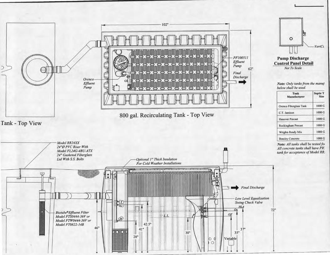
Tank - Top View
----------~-Model RR24XX
)
24"@ PVC Riser With Model FL24G-4BU-ATX 24" Gasketed Fiberglass Lid With S.S. Bolts
Biotube®Effluent Filter Model FTS0444-36Vor Model FTW0444-36V or Model FT0822-14B
1-------------102" ----------~
62"
Discharge liL 11
.....
800 gal. Recirculating Tank- Top View
0
VeriCc
Pump Discharge Control Panel Detail
Not To Scale
72"
Note: Only tanks from the manu) below shall be used.
Tank SepticT Manufacturer Size
Orenco Fiberglass Tank IOOOG
C.T. Jamison IOOOG
Hanover Precast IOOOG
Rockingham Precast IOOOG
Wrights Ready Mix IOOOG
Beasley Concrete IOOOG
Note: All tanks shall be testedfOJ All concrete tanks shall have PR: tank for acceptance of Model RR.
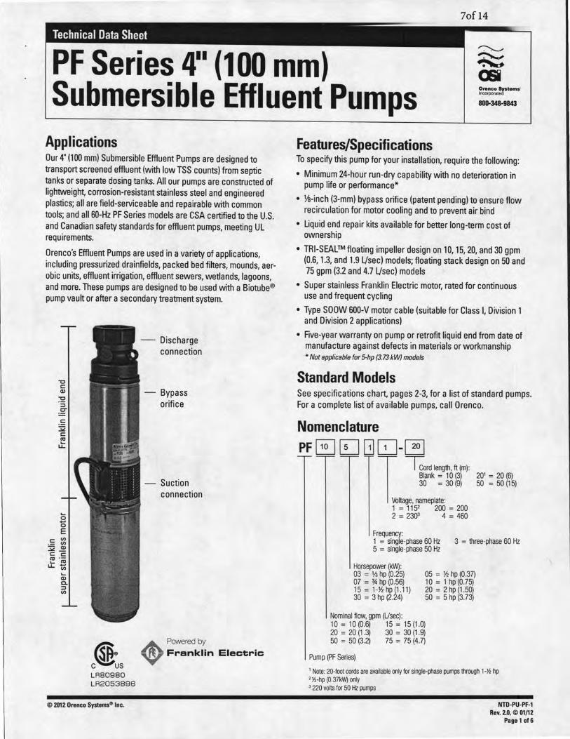
7of14
Technical Data Sheet
PF Series 4 .. (100 mm) Submersible Effluent Pumps Ontnco Sptems·
Incorporated
8011-348-9843
Applications Our 4" (100 mm) Submersible Effluent Pumps are designed to transport screened effluent (with low TSS counts) from septic tanks or separate dosing tanks. All our pumps are constructed of lightweight, corrosion-resistant stainless steel and engineered plastics; all are field-serviceable and repairable with common tools; and all 60-Hz PF Series models are GSA certified to the U.S. and Canadian safety standards for effluent pumps, meeting UL requirements.
Orenco's Effluent Pumps are used in a variety of applications, including pressurized drainfields, packed bed filters, mounds, aerobic units, effluent irrigation, effluent sewers, wetlands, lagoons, and more. These pumps are designed to be used with a Biotube® pump vault or after a secondary treatment system.
"0 c::
-Discharge connection
Q) - Bypass :S orifice g c::
::;;;: c:: ro ....
LL.
.... 0
b E
·= ~ - Q) ..>t!._ c:: c:: ~ ·;o u.t;
.... Q) 0.. ::I V)
- Suction connection
A Poweredby
c®~s ~ Franklin Electric
LR80980 LR2053896
© 2012 Orenco Systems<» Inc.
Features/Specifications To specify this pump for your installation, require the following:
• Minimum 24-hour run-dry capability with no deterioration in pump life or performance*
• Yfl-inch (3-mm) bypass orifice (patent pending) to ensure flow recirculation for motor cooling and to prevent air bind
• Liquid end repair kits available for better long-term cost of ownership
• TRI-SEAL™ floating impeller design on 10, 15, 20, and 30 gpm (0.6, 1.3, and 1.9 Ljsec) models; floating stack design on 50 and 75 gpm (3.2 and 4.7 Ljsec) models
• Super stainless Franklin Electric motor, rated for continuous use and frequent cycling
• Type SOOW 600-V motor cable (suitable for Class I, Division 1 and Division 2 applications)
• Five-year warranty on pump or retrofit liquid end from date of manufacture against defects in materials or workmanship * Not applicable for 5-hp (3.73 kW) models
Standard Models See specifications chart, pages 2-3, for a list of standard pumps. For a complete list of available pumps, call Orenco.
Nomenclature PF E] (D GJ ~-@]
1 Tcord length, ft (m): Blank = 1 0 (3) 30 = 30 (9)
oltage, nameplate: 1 = 1152 200 = 200 2 = 2303 4 = 460
Frequency:
201 = 20 (6) 50 =50 (15)
1 = single-phase 60 Hz 3 = three-phase 60 Hz 5 = single-phase 50 Hz
Horsepower (kW): 03 = II.J hp (0.25) 07 = % hp (0.56) 15 = 1-J~ hp (1 .11) 30 = 3 hp (2.24)
Nominal flow, gpm (Usee):
05 = ~ hp (0.37) 10 = 1 hp (0.75) 20 = 2 hp (1.50) 50 = 5 hp (3.73)
10 = 10(0.6) 15 = 15(1.0) 20 = 20 (1 .3) 30 = 30 (1.9) 50 = 50 (3.2) 75 = 75 (4.7)
Pump (PF Series)
1 Note: 20-foot cords are available only for single-phase pumps through 1-Y.! hp 2 Y.!-hp (0.37kW) only 3 220 volts for 50 Hz pumps
NTO-PU-PF-1 Rev. 2.0, © 01/12
Page 1 of 6
8 of 14
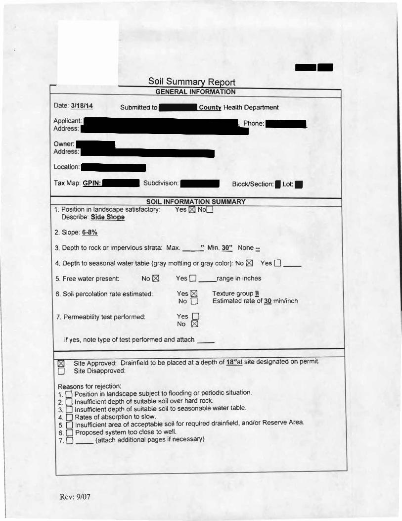
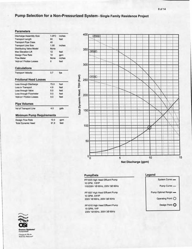
Pump Selection for a Non-Pressurized System- Single Family Residence Project
Parameters
Discharge Assembly Size 1.0FC
Transport Length 90
Transport Pipe Class 40
Transport Line Size 1.00
Distributing Valve Model None
Max Elevation Lift 12
Design Flow Rate 10
Flow Meter None
'Add-on' Friction Losses 0
Calculations
Transport Velocity 3.7
Frictional Head Losses
Loss through Discharge 75.0
Loss in Transport 4.9
Loss through Valve 0.0
Loss through Flowmeter 0.0
'Add-on' Friction Losses 0.0
Pipe Volumes
Vol ofTransport Line 4.0
Minimum Pump Requirements
Design Flow Rate
Total Dynamic Head
Orenco System•' Incorporated
Ch.mgi"!,"" \IVy'"' WVr/JDoa~JttWIIrn"'
10.0
91 .9
inches
feet
inches
feet
gpm
inches
feet
Ips
feet
feet
feet
feet
feet
gals
gpm
feet
--Ql Ql
!::. :r: 0 1--c ., Ql
:r: (.) ·e ., c: >. 0 iii -~
400 [PF101 0
-........ .......___
-........ -...,
350 fPF1om ......_
1'-----. r--.
300 ...__"
~~ 250
1---. -r--.
..............
200
150
1--
100
5 0
-- ...... -!---
PumpData
PF1005 High Head Effluent Pump
10 GPM, 1/2HP
115/230V 1060Hz, 200V 3060Hz
PF1007 High Head Effluent Pump
10 GPM, 3/4HP
230V 10 60Hz, 200V 30 60Hz
PF1010 High Head Effluent Pump
10 GPM, 1HP
230V 1060Hz, 200V 3060Hz
~ ~
!"-., .......
;-.... " .....
" '\, ...........
i"-.. '\. "\
" 1'\. '\
....... ,...... '\. b... f'\. \
t:'::,., '\. \. /
~ '\ '\ / ~ \ 1\
1 ~/i><.
"' r\ 1\ rv 1 \ \
/ r'f\ I \ v I 1\
/ I 1'\ I \ 11X 'l\ \
L I I 1'\ / ! I '\
v I
v ' --1--v I
v I I II '
I I
5 10 Net Discharge (gpm)
Legend
System Curve: -
Pump Curve: -
Pump Optimal Range: -
Operating Point: 0 Design Point: 0
15
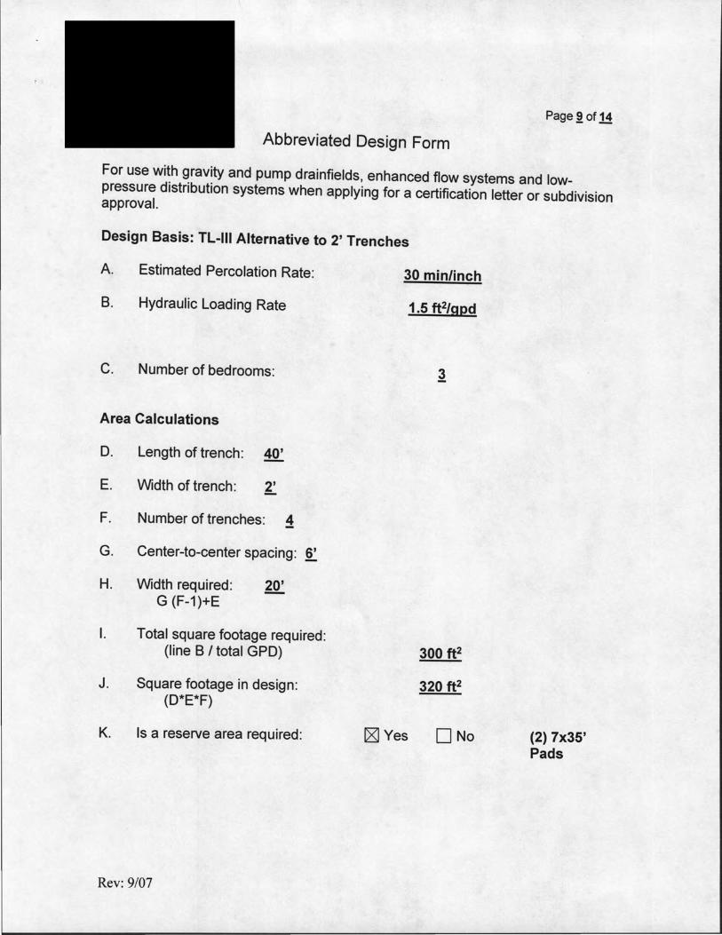
Page~ of 14
Abbreviated Design Form
For use with gravity and pump drainfields, enhanced flow systems and lowpressure distribution systems when applying for a certification letter or subdivision approval.
Design Basis: TL-111 Alternative to 2' Trenches
A. Estimated Percolation Rate:
B. Hydraulic Loading Rate
C. Number of bedrooms:
Area Calculations
D. Length of trench: 40'
E. Width of trench: 2'
F. Number of trenches: ~
G. Center-to-center spacing: 6'
H. Width required: 20'
I.
J.
K.
G (F-1)+E
Total square footage required: (line B I total GPO)
Square footage in design: (D*E*F)
Is a reserve area required:
Rev: 9/07
30 min/inch
1.5 ft2/gpd
300 ft2
320 ft2
[g] Yes 0No (2) 7x35' Pads
AdvanTex® O&M MANUAL SUPPLEMENTAL INFORMATION, AX20-RT
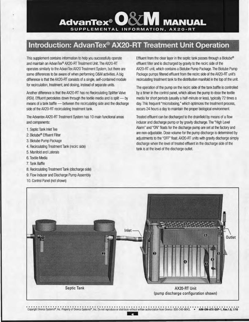
Introduction: AdvanTex® AX20-RT Treatment Unit Operation
This supplement contains information to help you successfully operate and maintain an AdvanTex® AX20-RTTreatment Unit. The AX20-RT operates similarly to the AdvanTexAX20 Treatment System, but there are some differences to be aware of when performing O&M activities. A big difference is that the AX20-RT consists of a single, self-contained module for recirculation, treatment, and dosing, instead of separate units.
Another difference is that the AX20-RT has no Recirculating Splitter Valve (RSV). Effluent percolates down through the textile media and is split- by means of a tank baffle - between the recirculating side and the discharge side of the AX20-RT recirculating treatment tank.
The Advantex AX20-RT Treatment System has 1 0 main functional areas and components:
1. Septic Tank lnletTee 2. Biotube® Effluent Filter 3. Biotube Pump Package 4. Recirculating Treatment Tank (recirc side) 5. Manifold and Laterals 6. Textile Media 7. Tank Baffle 8. Recirculating Treatment Tank (discharge side) 9. Flow Inducer and Discharge Pump Assembly 1 0. Control Panel (not shown)
Septic Tank
Effluent from the clear layer in the septic tank passes through a Biotube® effluent filter and is discharged by gravity to the recirc side of the AX20-RT unit, which contains a Biotube Pump Package. The Biotube Pump Package pumps filtered effluent from the recirc side of the AX20-RT unit's recirculating treatment tank to the distribution manifold in the top of the unit.
The operation of the pump on the recirc side of the tank baffle is controlled by a timer in the control panel, which allows the pump to dose the textile media for short periods (usually a half-minute or less), typically 72 times a day. This frequent "microdosing," which optimizes the treatment process, occurs 24 hours a day to maintain the proper biological environment.
Treated effluent can be discharged to the drainfield by means of a flow inducer and discharge pump or by gravity discharge. The "High Level Alarm" and "ON" floats for the discharge pump are set at the factory and are non-adjustable. Dose volume for the pump discharge is determined by adjustments to the "OFF" float. AX20-RT units with gravity discharge simply discharge when the level of treated effluent in the discharge side of the tank is at the level of the discharge outlet.
AX20-RT Unit (pump discharge configuration shown)
........................................................................................ Copyright Orenco Systems". Inc. Property of Orenco Systems"'. lnc. Do not reproduce or distribute without written authorization from Orenco: 800-348-9843. • AIM-OM-ATX-SUP-1, Rev.1.0, 1/10 ..
AdvanTex® O&M MANUAL SUPPLEMENTAL INFORMATION, AX20-RT
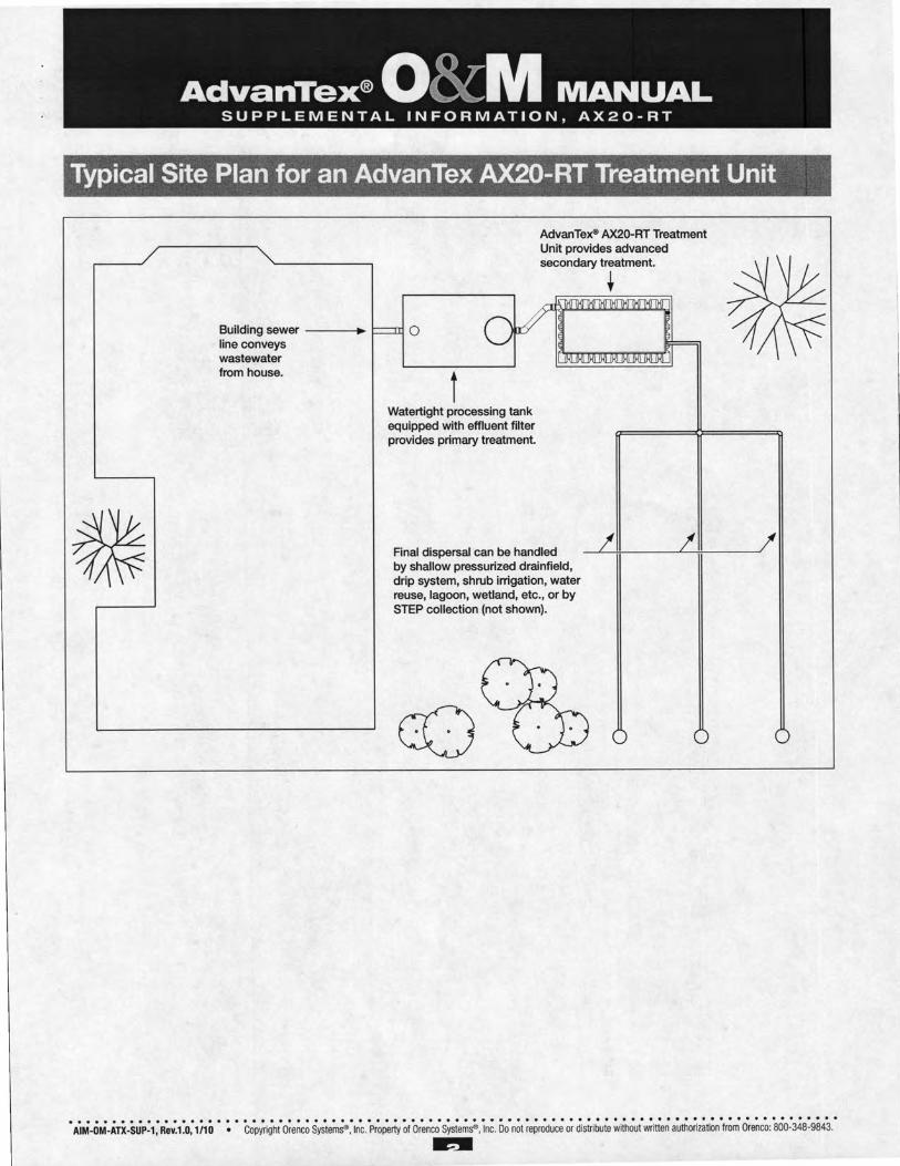
Typical Site Plan for an AdvanTex AX20-RT Treatment Unit
Building sewer -----. line conveys wastewater from house.
AdvanTex® AX20-RT Treatment Unit provides advanced secondary treatment.
0
t Watertight processing tank equipped with effluent filter provides primary treatment.
Final dispersal can be handled by shallow pressurized drainfield, drip system, shrub irrigation, water reuse, lagoon, wetland, etc., or by STEP collection (not shown).
t
AdvanTe:x® O&M MANUAL SUPPLEMENTAL INFORMATION, AX20-RT
AdvanTex O&M Manual: Changes Specific to the AX20-RT
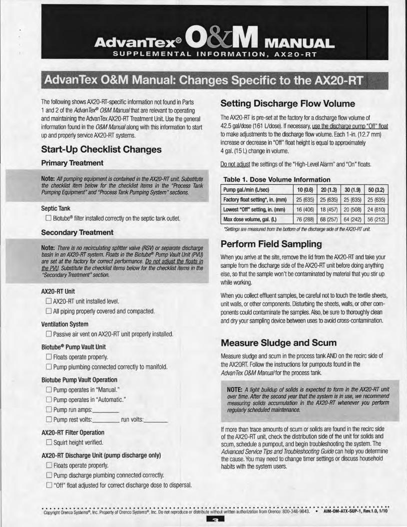
The following shows AX20-RT-specific information not found in Parts 1 and 2 of the AdvanTe>fP O&M Manual that are relevant to operating and maintaining the AdvanTex AX20-RTTreatment Unit. Use the general information found in the O&M Manual along with this information to start up and properly service AX20-RT systems.
Start-Up Checklist Changes Primary Treatment
Note: All pumping equipment is contained in the AX20-RT unit Substitute the checklist item below for the checklist items in the "Process Tank Pumping Equipment" and "Process Tank Pumping System" sections.
Septic Tank
0 Biotube® filter installed correctly on the septic tank outlet.
Secondary Treatment
Note: There is no recirculating splitter valve (RSV) or separate discharge basin in an AX20-RT system. Roats in the Biotub~ Pump Vault Unit (PVU) are set at the factory for correct performance. Do not adjust the floats in JM.W. Substitute the checklist items below for the checklist items in the "Secondary Treatment" section.
AX20-RT Unit
0 AX20-RT unit installed level.
0 All piping properly covered and compacted.
Ventilation System
0 Passive air vent on AX20-RT unit properly installed.
Biotube® Pump Vault Unit
0 Floats operate properly.
0 Pump plumbing connected correctly to manifold.
Biotube Pump Vault Operation
0 Pump operates in "Manual. "
0 Pump operates in "Automatic. " 0 Pump run amps: __ _
0 Pump rest volts: ___ run volts: __ _
AX20-RT Filter Operation
0 Squirt height verified.
AX20-RT Discharge Unit (pump discharge only)
0 Floats operate properly.
0 Pump discharge plumbing connected correctly.
0 "Off" float adjusted for correct discharge dose to dispersal.
Setting Discharge Flow Volume The AX20-RT is pre-set at the factory for a discharge flow volume of 42.5 gal/dose (161 Udose). If necessary, use the discharae pump "Off" float to make adjustments to the discharge flow volume. Each 1-in. (12.7 mm) increase or decrease in "Off" float height is equal to approximately 4 gal. (15 L) change in volume.
Do not adjust the settings of the "High-Level Alarm" and "On" floats.
Table 1. Dose Volume Information
Pump gaJJmin (Usee) 10 (0.6) 20 (1.3) 30 (1.9) 50(3.2)
Factory float setting*, in. (mm) 25 (635) 25 (635) 25 (635) 25 (635)
Lowest "Off" setting, in. (mm) 16 (406) 18 (457) 20 (508) 24 (610)
Max dose volume, gal. (L) 76 (288) 68 (257) 64 (242) 56 (212)
"Settings are measured from the tottom of the discharge side of the AX20-RT unit.
Perform Field Sampling When you arrive at the site, remove the lid from the AX20-RT and take your sample from the discharge side of the AX20-RT unit before doing anything else, so that the sample won't be contaminated by material that you stir up while working.
When you collect effluent samples, be careful not to touch the textile sheets, unit walls, or other components. Disturbing the sheets, walls, or other components could contaminate the samples. Also, be sure to thoroughly clean and dry your sampling device between uses to avoid cross-contamination.
Measure Sludge and Scum Measure sludge and scum in the process tank AND on the recirc side of the AX20RT. Follow the instructions for pumpouts found in the AdvanTex O&M Manual for the process tank.
NOTE: A light buildup of solids is expected to form in the AX20-RT unit over time. After the second year that the system is in use, we recommend measuring solids accumulation in the AX20-RT whenever you perform regularly scheduled maintenance.
If more than trace amounts of scum or solids are found in the recirc side of the AX20-RT unit, check the distribution side of the unit for solids and scum, schedule a pumpout, and begin troubleshooting the system. The Advanced Service Tips and Troubleshooting Guide can help you determine the cause. You may need to change timer settings or discuss household habits with the system users.
........................................................................................ Copyright Orenco Systems". Inc. Property of Orenco Systems"'. Inc. Do not reproduce or distribute without written authorization from Orenco: 800-348-9843. • AIM-OM-ATX-SUP-1 , Rev.1.0, 1110
~
AdvanTex® O&M MANUAL SUPPLEMENTAL INFORMATION, AX20-RT
Notes
.................................................................... AIM-OM-ATX-SUP-1, Rev.1 .0, 1/10 Copyright Orenco Systems" . Inc. Property of Orenco Systems" . Inc. Do not reproduce or distribute without written authorization from Orenco: 800-348-9843. ....
Page 14 of 14
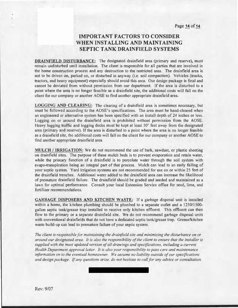
IMPORTANT FACTORS TO CONSIDER
WHEN INSTALLING AND MAINTAINING
SEPTIC TANK DRAINFIELD SYSTEMS
DRAINFIELD DISTURBANCE: The designated drainfield area (primary and reserve), must remain undisturbed until installation. The client is responsible for all parties that are involved in the home construction process and any destruction to the restricted area. The drainfield area is not to be driven on, parked on, or disturbed in anyway (i.e. soil compaction). Vehicles (trucks,tractors, and heavy equipment) especially should avoid this area. Our design package is final and cannot be deviated from without permission from our department. If the area is disturbed to a point where the area is no longer feasible as a drain.field site, the additional costs will fall on the client for our company or another AOSE to find another appropriate drainfield area.
LOGGING AND CLEARING: The clearing of a drainfield area is sometimes necessary, but must be followed according to the AOSE's specifications. The area must be hand-cleared when an engineered or alternative system has been specified with an install depth of 24 inches or less. Logging on or around the drainfield area is prohibited without permission from the AOSE. Heavy logging traffic and logging decks must be kept at least 50' feet away from the designated area (primary and reserve). If the area is disturbed to a point where the area is no longer feasible as a drainfield site, the additional costs will fall on the client for our company or another AOSE to find another appropriate drainfield area.
MULCH/ IRRIGATION: We do not recommend the use of bark, sawdust, or plastic sheeting on drain field sites. The purpose of these mulch beds is to prevent evaporation and retain water, while the primary function of a drainfield is to percolate water through the soil system with evapo-transpiration being an integral part of that process. Mulch can lead to an early failing of your septic system. Yard irrigation systems are not recommended for use on or within 25 feet of the drainfield trenches. Additional water added to the drainfield area can increase the likelihood of premature drainfield failure. The drainfield should be graded and seeded and maintained as a lawn for optimal performance. Consult your local Extension Service office for seed, lime, and fertilizer recommendations.
GARBAGE DISPOSERS AND KITCHEN WASTE: If a garbage disposal unit is installed within a home, the kitchen plumbing should be plumbed to a separate outlet and a 1250/1500-gallon septic tank/grease trap installed to receive only kitchen effluent. This effluent can then flow to the primary or a separate drainfield site. We do not recommend garbage disposal units with conventional drainfields that do not have a dedicated septic tank/grease trap. Grease/kitchen waste build-up can lead to premature failure of your septic system.
The client is responsible for maintaining the drainfield site and minimizing the disturbance on or around our designated area. It is also the responsibility of the client to ensure that the installer is supplied with the most updated version of all drawings and specifications, including a current Health Department approval letter. It is also your responsibility to pass care and maintenance information on to the eventual homeowner. We assume no liability outside of our specifications and design package. If any questions arise, do not hesitate to call for any advice or consultation.
Rev: 9/07